US7570663B2 - System and method for processing packets according to concurrently reconfigurable rules - Google Patents
System and method for processing packets according to concurrently reconfigurable rulesDownload PDFInfo
- Publication number
- US7570663B2 US7570663B2US11/189,172US18917205AUS7570663B2US 7570663 B2US7570663 B2US 7570663B2US 18917205 AUS18917205 AUS 18917205AUS 7570663 B2US7570663 B2US 7570663B2
- Authority
- US
- United States
- Prior art keywords
- rules
- packet
- rule
- memory
- network
- Prior art date
- Legal status (The legal status is an assumption and is not a legal conclusion. Google has not performed a legal analysis and makes no representation as to the accuracy of the status listed.)
- Expired - Lifetime, expires
Links
- 238000012545processingMethods0.000titleclaimsabstractdescription227
- 238000000034methodMethods0.000titleclaimsabstractdescription102
- 230000006870functionEffects0.000claimsabstractdescription56
- 230000009471actionEffects0.000claimsabstractdescription50
- 230000015654memoryEffects0.000claimsdescription185
- 230000004044responseEffects0.000claimsdescription29
- 230000005540biological transmissionEffects0.000claimsdescription17
- 230000000694effectsEffects0.000claimsdescription15
- 230000001419dependent effectEffects0.000claimsdescription5
- 230000008569processEffects0.000abstractdescription32
- 230000002708enhancing effectEffects0.000abstractdescription3
- 238000013519translationMethods0.000description183
- 230000014616translationEffects0.000description183
- 238000004891communicationMethods0.000description42
- 238000011144upstream manufacturingMethods0.000description31
- 238000007726management methodMethods0.000description26
- 238000001914filtrationMethods0.000description19
- 238000005516engineering processMethods0.000description18
- 230000002441reversible effectEffects0.000description18
- 239000000872bufferSubstances0.000description17
- 230000003287optical effectEffects0.000description15
- 230000001965increasing effectEffects0.000description12
- 238000012546transferMethods0.000description12
- 238000004458analytical methodMethods0.000description11
- 238000012544monitoring processMethods0.000description10
- 239000004744fabricSubstances0.000description9
- 239000003607modifierSubstances0.000description8
- 238000013461designMethods0.000description7
- 238000010586diagramMethods0.000description7
- 239000000835fiberSubstances0.000description5
- 230000004048modificationEffects0.000description5
- 238000012986modificationMethods0.000description5
- 230000008520organizationEffects0.000description5
- 230000001360synchronised effectEffects0.000description5
- 241000282414Homo sapiensSpecies0.000description4
- 241000700605VirusesSpecies0.000description4
- 150000001875compoundsChemical group0.000description4
- 230000008878couplingEffects0.000description4
- 238000010168coupling processMethods0.000description4
- 238000005859coupling reactionMethods0.000description4
- 238000013497data interchangeMethods0.000description4
- 238000013500data storageMethods0.000description4
- 238000007689inspectionMethods0.000description4
- 230000002829reductive effectEffects0.000description4
- 230000003068static effectEffects0.000description4
- 102100032986CCR4-NOT transcription complex subunit 8Human genes0.000description3
- 101000942586Homo sapiens CCR4-NOT transcription complex subunit 8Proteins0.000description3
- 101001094629Homo sapiens Popeye domain-containing protein 2Proteins0.000description3
- 101000608230Homo sapiens Pyrin domain-containing protein 2Proteins0.000description3
- 230000008901benefitEffects0.000description3
- 238000011156evaluationMethods0.000description3
- 241000238366CephalopodaSpecies0.000description2
- 238000013459approachMethods0.000description2
- 230000002457bidirectional effectEffects0.000description2
- 230000000903blocking effectEffects0.000description2
- 238000010276constructionMethods0.000description2
- 230000007123defenseEffects0.000description2
- 230000001066destructive effectEffects0.000description2
- 238000001514detection methodMethods0.000description2
- RGNPBRKPHBKNKX-UHFFFAOYSA-NhexaflumuronChemical compoundC1=C(Cl)C(OC(F)(F)C(F)F)=C(Cl)C=C1NC(=O)NC(=O)C1=C(F)C=CC=C1FRGNPBRKPHBKNKX-UHFFFAOYSA-N0.000description2
- 230000000977initiatory effectEffects0.000description2
- 230000003993interactionEffects0.000description2
- 238000002955isolationMethods0.000description2
- 230000006855networkingEffects0.000description2
- 238000007781pre-processingMethods0.000description2
- 230000002123temporal effectEffects0.000description2
- 102100029368Cytochrome P450 2C18Human genes0.000description1
- 108020004414DNAProteins0.000description1
- 241000408659DarpaSpecies0.000description1
- 241001522296Erithacus rubeculaSpecies0.000description1
- 101000919360Homo sapiens Cytochrome P450 2C18Proteins0.000description1
- 241000721662JuniperusSpecies0.000description1
- RJKFOVLPORLFTN-LEKSSAKUSA-NProgesteroneChemical compoundC1CC2=CC(=O)CC[C@]2(C)[C@@H]2[C@@H]1[C@@H]1CC[C@H](C(=O)C)[C@@]1(C)CC2RJKFOVLPORLFTN-LEKSSAKUSA-N0.000description1
- 240000008042Zea maysSpecies0.000description1
- 235000005824Zea mays ssp. parviglumisNutrition0.000description1
- 235000002017Zea mays subsp maysNutrition0.000description1
- 230000004308accommodationEffects0.000description1
- 230000006978adaptationEffects0.000description1
- 230000004888barrier functionEffects0.000description1
- 230000006399behaviorEffects0.000description1
- 230000003139buffering effectEffects0.000description1
- 230000015556catabolic processEffects0.000description1
- 230000001413cellular effectEffects0.000description1
- 230000008859changeEffects0.000description1
- 238000001816coolingMethods0.000description1
- 235000005822cornNutrition0.000description1
- 230000005574cross-species transmissionEffects0.000description1
- 238000006731degradation reactionMethods0.000description1
- 238000012217deletionMethods0.000description1
- 230000037430deletionEffects0.000description1
- 238000002716delivery methodMethods0.000description1
- 239000006185dispersionSubstances0.000description1
- 230000009977dual effectEffects0.000description1
- 230000003203everyday effectEffects0.000description1
- 238000000605extractionMethods0.000description1
- 239000003292glueSubstances0.000description1
- 230000010365information processingEffects0.000description1
- 238000003780insertionMethods0.000description1
- 230000037431insertionEffects0.000description1
- 238000009434installationMethods0.000description1
- 230000002452interceptive effectEffects0.000description1
- 230000000670limiting effectEffects0.000description1
- PWPJGUXAGUPAHP-UHFFFAOYSA-NlufenuronChemical compoundC1=C(Cl)C(OC(F)(F)C(C(F)(F)F)F)=CC(Cl)=C1NC(=O)NC(=O)C1=C(F)C=CC=C1FPWPJGUXAGUPAHP-UHFFFAOYSA-N0.000description1
- 230000000873masking effectEffects0.000description1
- 230000007246mechanismEffects0.000description1
- 230000005012migrationEffects0.000description1
- 238000013508migrationMethods0.000description1
- 230000003071parasitic effectEffects0.000description1
- 230000036961partial effectEffects0.000description1
- 238000005192partitionMethods0.000description1
- 230000000737periodic effectEffects0.000description1
- 238000011045prefiltrationMethods0.000description1
- 230000000644propagated effectEffects0.000description1
- 238000010926purgeMethods0.000description1
- 238000011160researchMethods0.000description1
- 239000004065semiconductorSubstances0.000description1
- 238000012163sequencing techniqueMethods0.000description1
- 230000001052transient effectEffects0.000description1
- 230000001960triggered effectEffects0.000description1
- 239000002699waste materialSubstances0.000description1
Images


Classifications
- H—ELECTRICITY
- H04—ELECTRIC COMMUNICATION TECHNIQUE
- H04L—TRANSMISSION OF DIGITAL INFORMATION, e.g. TELEGRAPHIC COMMUNICATION
- H04L47/00—Traffic control in data switching networks
- H04L47/10—Flow control; Congestion control
- H—ELECTRICITY
- H04—ELECTRIC COMMUNICATION TECHNIQUE
- H04L—TRANSMISSION OF DIGITAL INFORMATION, e.g. TELEGRAPHIC COMMUNICATION
- H04L47/00—Traffic control in data switching networks
- H04L47/10—Flow control; Congestion control
- H04L47/19—Flow control; Congestion control at layers above the network layer
- H—ELECTRICITY
- H04—ELECTRIC COMMUNICATION TECHNIQUE
- H04L—TRANSMISSION OF DIGITAL INFORMATION, e.g. TELEGRAPHIC COMMUNICATION
- H04L61/00—Network arrangements, protocols or services for addressing or naming
- H04L61/45—Network directories; Name-to-address mapping
- H04L61/4505—Network directories; Name-to-address mapping using standardised directories; using standardised directory access protocols
- H04L61/4511—Network directories; Name-to-address mapping using standardised directories; using standardised directory access protocols using domain name system [DNS]
- H—ELECTRICITY
- H04—ELECTRIC COMMUNICATION TECHNIQUE
- H04L—TRANSMISSION OF DIGITAL INFORMATION, e.g. TELEGRAPHIC COMMUNICATION
- H04L63/00—Network architectures or network communication protocols for network security
- H04L63/02—Network architectures or network communication protocols for network security for separating internal from external traffic, e.g. firewalls
- H04L63/0227—Filtering policies
- H04L63/0263—Rule management
- H—ELECTRICITY
- H04—ELECTRIC COMMUNICATION TECHNIQUE
- H04L—TRANSMISSION OF DIGITAL INFORMATION, e.g. TELEGRAPHIC COMMUNICATION
- H04L69/00—Network arrangements, protocols or services independent of the application payload and not provided for in the other groups of this subclass
- H04L69/22—Parsing or analysis of headers
Definitions
- the Internetis growing by leaps and bounds. Everyday, more and more users log on to the Internet for the first time and these, and existing users are finding more and more content being made available to them.
- the Internethas become a universal medium for communications, commerce and information gathering.
- WWWWorld Wide Web
- many users of the Internethave come to refer to it as the “World Wide Wait.”
- intranetsare essentially private Internets for use by their employees. These intranets can become overloaded as well. Especially, when a company's intranet also provides connectivity to the Internet. In this situation, the intranet is not only carrying internally generated traffic but also Internet traffic generated by the employees.
- FIG. 1depicts an exemplary network for use with the preferred embodiments.
- FIG. 2depicts the operations of the Domain Name System of the exemplary network of FIG. 1 .
- FIG. 3depicts an exemplary content delivery system for use with the exemplary network of FIG. 1 .
- FIG. 4depicts a content delivery system for use with the network of FIG. 1 according to a first embodiment.
- FIG. 4Adepicts a block diagram of the content delivery system of FIG. 4 .
- FIG. 5depicts a content delivery system for use with the network of FIG. 1 according to a second embodiment.
- FIG. 5Adepicts a block diagram of the content delivery system of FIG. 5 .
- FIG. 6depicts a content delivery system for use with the network of FIG. 1 according to a third embodiment.
- FIG. 6Adepicts a block diagram of the content delivery system of FIG. 6 .
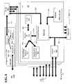
- FIG. 7depicts an edge adapter and packet interceptor according a fourth embodiment.
- FIG. 8depicts a block diagram of the packet analyzer/adapter of FIG. 7 .
- FIG. 9depicts a block diagram of a packet interceptor/analyzer according to a fifth embodiment.
- FIG. 1shows an exemplary network 100 for use with the presently preferred embodiments. It is preferred that the network 100 be a publicly accessible network, and in particular, the Internet. While, for the purposes of this disclosure, the disclosed embodiments will be described in relation to the Internet, one of ordinary skill in the art will appreciate that the disclosed embodiments are not limited to the Internet and are applicable to other types of public networks as well as private networks, and combinations thereof, and all such networks are contemplated.
- a networkinterconnects one or more computers so that they may communicate with one another, whether they are in the same room or building (such as a Local Area Network or LAN) or across the country from each other (such as a Wide Area Network or WAN).
- a networkis a series of points or nodes 126 interconnected by communications paths 128 . Networks can interconnect with other networks and can contain sub-networks.
- a node 126is a connection point, either a redistribution point or an end point, for data transmissions generated between the computers which are connected to the network.
- a node 126has a programmed or engineered capability to recognize and process or forward transmissions to other nodes 126 .
- the nodes 126can be computer workstations, servers, bridges or other devices but typically, these nodes 126 are routers or switches.
- a routeris a device or, in some cases, software in a computer, that determines the next network node 126 to which a piece of data (also referred to as a “packet” in the Internet context) should be forwarded toward its destination.
- the routeris connected to at least two networks or sub-networks and decides which way to send each information packet based on its current understanding of the state of the networks to which it is connected.
- a routeris located at any juncture of two networks, sub-networks or gateways, including each Internet point-of-presence (described in more detail below).
- a routeris often included as part of a network switch.
- a routertypically creates or maintains a table of the available routes and their conditions and uses this information along with distance and cost algorithms to determine the best route for a given packet.
- a packetmay travel through a number of network points, each containing additional routers, before arriving at its destination.
- the communications paths 128 of a network 100can be coaxial cable, fiber optic cable, telephone cable, leased telephone lines such as T1 lines, satellite links, microwave links or other communications technology as is known in the art.
- the hardware and software which allows the network to functionis known as the “infrastructure.”
- a network 100can also be characterized by the type of data it carries (voice, data, or both) or by the network protocol used to facilitate communications over the network's 100 physical infrastructure.
- the Internetin particular, is a publicly accessible worldwide network 100 which primarily uses the Transport Control Protocol and Internet Protocol (“TCP/IP”) to permit the exchange of information.
- TCP/IPTransport Control Protocol and Internet Protocol
- the Internetsupports several applications protocols including the Hypertext Transfer Protocol (“HTTP”) for facilitating the exchange of HTML/World Wide Web (“WWW”) content, File Transfer Protocol (“FTP”) for the exchange of data files, electronic mail exchange protocols, Telnet for remote computer access and Usenet (“NNTP” or Network News Transfer Protocol) for the collaborative sharing and distribution of information.
- HTTPHypertext Transfer Protocol
- WWWWWorld Wide Web
- FTPFile Transfer Protocol
- TelnetTelnet for remote computer access
- UsenetTelnet for remote computer access
- NTPNetwork News Transfer Protocol
- the Internetcan be thought of as a web of intermediate network nodes 126 and communications paths 128 interconnecting those network nodes 126 which provide multiple data transmission routes from any given point to any other given point on the network 100 (i.e. between any two computers connected to the network 100 ).
- the Internetcan also be thought of as a collection of interconnected sub-networks wherein each sub-network contains a portion of the intermediate network nodes 126 and communications paths 128 .
- the division of the Internet into sub-networksis typically geographically based, but can also be based on other factors such as resource limitations and resource demands. For example, a particular city may be serviced by one or more Internet sub-networks provided and maintained by competing Internet Service Providers (“ISPs”) (discussed in more detail below) to support the service and bandwidth demands of the residents.
- ISPsInternet Service Providers
- an intranetis a private network contained within an enterprise, such as a corporation, which uses the TCP/IP and other Internet protocols, such as the World Wide Web, to facilitate communications and enhance the business concern.
- An intranetmay contain its own Domain Name Server (“DNS”) and may be connected to the Internet via a gateway, i.e., an intra-network connection, or gateway in combination with a proxy server or firewall, as are known in the art.
- DNSDomain Name Server
- clients 102 , 104 , 106 and servers 108 , 110 , 112are shown coupled with the network 100 .
- the phrase “coupled with”is defined to mean directly connected to or indirectly connected with, through one or more intermediate components. Such intermediate components may include both hardware and software based components.
- the network 100facilitates communications and interaction between one or more of the clients 102 , 104 , 106 and one or more of the servers 108 , 110 , 112 (described in more detail below).
- the network 100also facilitates communications and interaction among one or more of the clients 102 , 104 , 106 , e.g.
- a client 102 , 104 , 106may include a personal computer workstation, mobile or otherwise, wireless device such as a personal digital assistant or cellular telephone, an enterprise scale computing platform such as a mainframe computer or server or may include an entire intranet or other private network which is coupled with the network 100 .
- a client 102 , 104 , 106initiates data interchanges with other computers, such as servers 108 , 110 , 112 coupled with the network 100 . These data interchanges most often involve the client requesting data or content from the other computer and the other computer providing that data or content in response to the request.
- the other computer coupled with the networkcan “push” data or content to the client 102 , 104 , 106 without it first being requested.
- an electronic mail server 108 , 110 , 112may automatically push newly received electronic mail over the network 100 to the client 102 , 104 , 106 as the new electronic mail arrives, alleviating the client 102 , 104 , 106 from first requesting that new mail be sent. It will be apparent to one of ordinary skill in the art that there can be many clients 102 , 104 , 106 coupled with the network 100 .
- a server 108 , 110 , 112may include a personal computer workstation, an enterprise scale computing platform or other computer system as are known in the art.
- a server 108 , 110 , 112typically responds to requests from clients 102 , 104 , 106 over the network 100 .
- the server 108 , 110 , 112provides the requested data or content to the client 102 , 104 , 106 which may or may not require some sort of processing by the server 108 , 110 , 112 or another computer to produce the requested response.
- a client 102 , 104 , 106may also be a server 108 , 110 , 112 and vice versa depending upon the nature of the data interchange taking place, e.g. peer-to-peer architectures.
- a client 102 , 104 , 106requests or receives content and is separate from the server 108 , 110 , 112 which provides the content (whether requested or not, i.e. pushed).
- servers 108 , 110 , 112are World Wide Web servers serving Web pages and/or Web content to the clients 102 , 104 , 106 (described in more detail below). It will be apparent to one of ordinary skill in the art that there can be many servers 108 , 110 , 112 coupled with the network 100 .
- Clients 102 , 104 , 106are each coupled with the network 100 at a point of presence (“POP”) 114 , 116 .
- the POP 114 , 116is the connecting point which separates the client 102 , 104 , 106 from the network 100 .
- the POP 114 , 116is the logical (and possibly physical) point where the public network 100 ends, after which comes the private (leased or owned) hardware or private (leased or owned) network of the client 102 , 104 , 106 .
- a POP 114 , 116is typically provided by a service provider 118 , 120 , such as an Internet Service Provider (“ISP”) 118 , 120 , which provides connectivity to the network 100 on a fee for service basis.
- ISPInternet Service Provider
- a POP 114 , 116may actually reside in rented space owned by telecommunications carrier such as AT&T or Sprint to which the ISP 118 , 120 is connected.
- a POP 114 , 116may be coupled with routers, digital/analog call aggregators, servers 108 , 110 , 112 , and frequently frame relay or ATM switches.
- a POP 114 , 116may also contain cache servers and other content delivery devices.
- a typical ISP 118 , 120may provide multiple POP's 114 , 116 to simultaneously support many different clients 102 , 104 , 106 connecting with the network 100 at any given time.
- a POP 114 , 116is typically implemented as a piece of hardware such as a modem or router but may also include software and/or other hardware such as computer hardware to couple the client 102 , 104 , 106 with the network 100 both physically/electrically and logically (as will be discussed below).
- the client 102 , 104 , 106connects to the POP 114 , 116 over a telephone line or other transient or dedicated connection.
- the ISP 118 , 120provides a modem as the POP 114 , 116 to which the client 102 , 104 , 106 can dial in and connect to via a standard telephone line.
- the POP 114 , 116may include a gateway router which is connected to an internal gateway router within the client 102 , 104 , 106 by a high speed dedicated communication link such as T1 line or a fiber optic cable.
- a service provider 118 , 120will generally provide POP's 114 , 116 which are geographically proximate to the clients 102 , 104 , 106 being serviced. For dial up clients 102 , 104 , 106 , this means that the telephone calls can be local calls. For any client 102 , 104 , 106 , a POP which is geographically proximate typically results in a faster and more reliable connection with the network 100 .
- Servers 108 , 110 , 112are also connected to the network 100 by POP's 114 , 116 . These POP's 114 , 116 typically provide a dedicated, higher capacity and more reliable connection to facilitate the data transfer and availability needs of the server 108 , 110 , 112 .
- the service provider 118 , 120may provide many geographically dispersed POP's 114 , 116 to facilitate connecting with the network 100 from wherever the client 102 , 104 , 106 may roam or alternatively have agreements with other service providers 118 , 120 to allow access by each other's customers.
- Each service provider 118 , 120 , along with its POP's 114 , 116 and the clients 102 , 104 , 106effectively forms a sub-network of the network 100 .
- Each upstream service provider 118 , 120along with its downstream service providers 118 , 120 again forms a sub-network of the network 100 .
- Peeringis the term used to describe the arrangement of traffic exchange between Internet service providers (ISPs) 118 , 120 .
- ISPsInternet service providers
- peeringis the agreement to interconnect and exchange routing information.
- larger ISP's 118 , 120 with their own backbone networksagree to allow traffic from other large ISP's 118 , 120 in exchange for traffic on their backbones. They also exchange traffic with smaller service providers 118 , 120 so that they can reach regional end points where the POP's 114 , 116 are located. Essentially, this is how a number of individual sub-network owners compose the Internet. To do this, network owners and service providers 118 , 120 , work out agreements to carry each other's network traffic. Peering requires the exchange and updating of router information between the peered ISP's 118 , 120 , typically using the Border Gateway Protocol (BGP).
- Border Gateway ProtocolBorder Gateway Protocol
- Peering partiesinterconnect at network focal points such as the network access points (NAPs) in the United States and at regional switching points.
- NAPsnetwork access points
- Private peeringis peering between parties that are bypassing part of the publicly accessible backbone network through which most Internet traffic passes.
- some service providers 118 , 120have local peering arrangements instead of, or in addition to, peering with a backbone service provider 118 , 120 .
- a network access pointis one of several major Internet interconnection points that serve to tie all of the service providers 118 , 120 together so that, for example, an AT&T user in Portland, Oreg. can reach the Web site of a Bell South customer in Miami, Fla.
- the NAPsprovide major switching facilities that serve the public in general.
- Service providers 118 , 120apply to use the NAP facilities and make their own inter-company peering arrangements. Much Internet traffic is handled without involving NAPs, using peering arrangements and interconnections within geographic regions.
- the network 100can be further logically described to comprise a core 122 and an edge 124 .
- the core 122 of the network 100includes the servers 108 , 110 , 112 and the bulk of the network 100 infrastructure, as described above, including larger upstream service providers 118 , 120 , and backbone communications links, etc. Effectively, the core 122 includes everything within the network 100 up to the POP's 114 , 116 .
- the POP's 114 , 116 and their associated hardwarelie at the edge 124 of the network 100 .
- the edge 124 of the network 100is the point where clients 102 , 104 , 106 , whether single devices, computer workstations or entire corporate internal networks, couple with the network 100 .
- the edge 124 of the network 100may include additional hardware and software such as Domain Name Servers, cache servers, proxy servers and reverse proxy servers as will be described in more detail below.
- the total available bandwidth of the network 100is diluted over more and more lower cost and lower bandwidth communications paths.
- bandwidth over the higher capacity backbone interconnectionstends to be more costly than bandwidth at the edge 124 of the network 100 .
- high bandwidth interconnectionsare more difficult to implement and therefore rarer and more expensive than low bandwidth connections. It will be appreciated, that even as technology progresses, newer and higher bandwidth technologies will remain more costly than lower bandwidth technologies.
- HTTPWorld Wide Web
- a technical definition of the World Wide Webis all the resources and users on the Internet that are using the Hypertext Transfer Protocol (“HTTP”).
- HTTPis the set of rules for exchanging data in the form of files (text, graphic images, audio, video, and other multimedia files, such as streaming media and instant messaging), also known as Web content, between clients 102 , 104 , 106 and servers 108 , 110 , 112 .
- Servers 108 , 110 , 112which serve Web content are also known as Web servers 108 , 110 , 112 .
- Any Web server 108 , 110 , 112contains, in addition to the files it can serve, an HTTP daemon, a program that is designed to wait for HTTP requests and handle them when they arrive.
- a personal computer Web browser programsuch as MicrosoftTM Internet Explorer, is an HTTP client program (a program which runs on the client 102 , 104 , 106 ), sending requests to Web servers 108 , 110 , 112 .
- the browserWhen the browser user enters file requests by either “opening” a Web file (typing in a Uniform Resource Locator or URL) or clicking on a hypertext link, the browser builds an HTTP request and sends it to the Web server 108 , 110 , 112 indicated by the URL.
- the HTTP daemon in the destination server 108 , 110 , 112receives the request and, after any necessary processing, returns the requested file to the client 102 , 104 , 106 .
- the Web content which a Web server typically servesis in the form of Web pages which consist primarily of Hypertext Markup Language.
- Hypertext Markup Language(“HTML”) is the set of “markup” symbols or codes inserted in a file usually containing text intended for display on a World Wide Web browser. The markup tells the Web browser how to display a Web page's content for the user.
- the individual markup codesare referred to as elements or tags.
- Web pagescan further include references to other files which are stored separately from the HTML code, such as image or other multimedia files to be presented in conjunction with the text Web content.
- a Web siteis a related collection of Web files/pages that includes a beginning HTML file called a home page.
- a company or an individualtells someone how to get to their Web site by giving that person the address or domain name of their home page (the addressing scheme of the Internet and the TCP/IP protocol is described in more detail below).
- From the home pagelinks are typically provided, either directly or through intermediate pages, to all the other pages (HTML files) located on their site.
- the Web site for IBMTMhas the home page address of http:/www.ibm.com.
- the home page addressmay include a specific file name like index.html but, as in IBM's case, when a standard default name is set up, users don't have to enter the file name.
- IBM's home page addressleads to thousands of pages, but a Web site may also consist of just a few pages.
- a Web sitecan be confused with a Web server 108 , 110 , 112 .
- a server 108 , 110 , 112is a computer that holds and serves the HTML files, images and other data for one or more Web sites.
- a very large Web sitemay be spread over a number of servers 108 , 110 , 112 in different geographic locations or one server 108 , 110 , 112 may support many Web sites.
- a Web hosting companymay provide server 108 , 110 , 112 facilities to a number of Web sites for a fee.
- Web sitescan also contain links to pages or files on other Web sites.
- the network 100facilitates communications between clients 102 , 104 , 106 and servers 108 , 110 , 112 . More specifically, the network 100 facilitates the transmission of HTTP requests from a client 102 , 104 , 106 to a server 108 , 110 , 112 and the transmission of the server's 108 , 110 , 112 , response to that request, the requested content, back to the client 102 , 104 , 106 . In order to accomplish this, each device coupled with the network 100 , whether it be a client 102 , 104 , 106 or a server 108 , 110 , 112 must provide a unique identifier so that communications can be routed to the correct destination.
- these unique identifierscomprise domain names (which generally will include World Wide Web Uniform Resource Locators or “URL's”) and Internet Protocol addresses or “IP” addresses. Every client 102 , 104 , 106 and every server 108 , 110 , 112 must have a unique IP address so that the network 100 can reliably route communications to it. Additionally, clients 102 , 104 , 106 and servers 108 , 110 , 112 can be coupled with proxy servers (forward, reverse or transparent), discussed in more detail below, which allow multiple clients 102 , 104 , 106 or multiple servers 108 , 110 , 112 to be associated with a single domain name or a single IP address.
- proxy serversforward, reverse or transparent
- a particular server 108 , 110 , 112may be associated with multiple domain names and/or IP addresses for more efficient handling of requests or to handle multiple content providers, e.g. multiple Web sites, on the same server 108 , 110 , 112 .
- a POP 114 , 116provides the connecting point for any particular client 102 , 104 , 106 to connect to the network 100 , it is often satisfactory to provide each POP 114 , 116 with a single unique domain name and IP address since the POP 114 , 116 will reliably deliver any communications received by it to its connected client 102 , 104 , 106 .
- the client 102 , 104 , 106may have its own internal hardware, software and addressing scheme (which may also include domain names and IP addresses) to reliably deliver data received from the POP 114 , 116 to the ultimate destination within the private network client 102 , 104 , 106 .
- the Internetis a collection of interconnected sub-networks whose users communicate with each other. Each communication carries the address of the source and destination sub-networks and the particular machine within the sub-network associated with the user or host computer at each end. This address is called the IP address (Internet Protocol address).
- IP addressInternet Protocol address
- the IP addressis a 32 bit binary number divided into four 8 bit octets. This 32-bit IP address has two parts: one part identifies the source or destination sub-network (with the network number) and the other part identifies the specific machine or host within the source or destination sub-network (with the host number).
- IP addressAn organization can use some of the bits in the machine or host part of the address to identify a specific sub-network within the sub-network. Effectively, the IP address then contains three parts: the sub-network number, an additional sub-network number, and the machine number.
- IP addresseshave very little meaning to ordinary users/human beings.
- a symbolic addressing schemeoperates in parallel with the IP addressing scheme.
- each client 102 , 104 , 106 and server 108 , 110 , 112is also given a “domain name” and further, individual resources, content or data are given a Uniform Resource Locator (“URL”) based on the domain name of the server 108 , 110 , 112 on which it is stored.
- URLUniform Resource Locator
- a companymay have a domain name for its servers 108 , 110 , 112 which is the company name, i.e., IBM Corporation's domain name is ibm.com.
- the portion of the domain name immediately following the period or “dot”is used to identify the type of organization to which the domain name belongs.
- Theseare called “top-level” domain names and include com, edu, org, mil, gov, etc.
- Comindicates a corporate entity
- eduindicates an educational institution
- milindicates a military entity
- govindicates a government entity.
- the text strings which make up domain namesmay be arbitrary and that they are designed to have relevant symbolic meaning to the users of the network 100 .
- a URLtypically includes the domain name of the provider of the identified resource, an indicator of the type of resource and an identifier of the resource itself. For example, for the URL “http://www.ibm.com/index.html”, http identifies this resource as a hypertext transfer protocol compatible resource, www.ibm.com is the domain name (again, the www is arbitrary and typically is added to indicate to a user that the server 108 , 110 , 112 , associated with this domain name is a world wide Web server), and index.html identifies a hypertext markup language file named “index.html” which is stored on the identified server 108 , 110 , 112 .
- Domain namesmake the network 100 easier for human beings to utilize it, however the network infrastructure ultimately uses IP addresses, and not domain names, to route data to the correct destination. Therefore, a translation system is provided by the network 100 to translate the symbolic human comprehensible domain names into IP addresses which can then be used to route the communications.
- DNSDomain Name System
- the DNSis the way that Internet domain names are located and translated into IP addresses.
- the DNSis a distributed translation system of address translators whose primary function is to translate domain names into IP addresses and vice versa. Due to the ever expanding number of potential clients 102 , 104 , 106 and servers 108 , 110 , 112 coupled with the network 100 (currently numbering in the millions), maintaining a single central list of domain name/IP address correspondences would be impractical.
- a DNS servertypically located within close geographic proximity to a service provider 118 , 120 (and likely provided by that service provider 118 , 120 ), handles requests to translate the domain names serviced by that service provider 118 , 120 or forwards those requests to other DNS servers coupled with the Internet for translation.
- DNS translationscan be forward or reverse.
- Forward DNS translationuses an Internet domain name to find an IP address.
- Reverse DNS translationuses an Internet IP address to find a domain name.
- a userenters the address or URL for a Web site or other resource into their browser program, the address is transmitted to a nearby router which does a forward DNS translation in a routing table to locate the IP address.
- Forward DNS translationsare the more common translation since most users think in terms of domain names rather than IP addresses.
- the domain name partis expressed as an IP address (sometimes called a dot address) and wants to be able to see its domain name, to for example, attempt to figure the identity of who is providing the particular resource.
- IP addresssometimes called a dot address
- the userwould perform a reverse DNS translation.
- the DNS translation servers provided on the Internetform a hierarchy through which any domain name can be “resolved” into an IP address. If a particular DNS translation server does not “know” the corresponding IP address of a given domain name, it “knows” other DNS translation servers it can “ask” to get that translation.
- This hierarchyincludes “top-level” DNS translation servers which “know” which resources (clients 102 , 104 , 106 or servers 108 , 110 , 112 ) have a particular top level domain identifier, i.e. com, gov, edu, etc. as described above.
- This hierarchyfurther continues all the way up to the actual resource (client 102 , 104 , 106 or server 108 , 110 , 112 ) which is typically affiliated with a DNS translation server which “knows” about it and its IP address.
- a particular DNS translation server“knows” of a translation when it exists in its table of translations and has not expired. Any particular translation will typically be associated with a Time to Live (“TTL”) which specifies a duration, time or date after which the translation expires.
- TTLTime to Live
- a DNS translation serverdoes not know the translation, because it is not in its routing table or it has expired, that DNS translation server will have to inquire up the hierarchical chain of DNS translation servers in order to make the translation. In this way, new domain name and IP address translations can be propagated through the DNS translation server hierarchy as new resources are added and old resources are assigned new addresses.
- FIG. 2there is shown a diagram illustrating the basic operation of the Domain Name System 200 .
- clients 102 , 104 , 106Depicted in the figure are clients 102 , 104 , 106 , labeled “Client 1 ”, “Client 2 ” and “Client 3 .”
- Clients 1 and 2are coupled with POP's 114 provided by service provider 120 , labeled “POP 1 A” and “POP 1 B.”
- Client 3is coupled with a POP (not shown) provided by service provider 118 , labeled “POP 2 .”
- service providers 118 , 120may provide additional POP's 114 for other clients 102 , 104 , 106 as described above.
- Service provider 120is shown further coupled with service provider 118 , a server 108 , labeled “Server 1 ”, preferably a Web server and more preferably an entire Web site which may comprise multiple sub-servers (not shown) as discussed above, and a top-level DNS translation server 202 , labeled “DNS Top”, all via the network 100 which is preferably the Internet.
- service provider 120further includes a DNS translation server 204 , labeled “DNS A” and routing and interconnection hardware 206 , as described above, to electrically and logically couple the POP's 114 with the network 100 .
- the service provider 120may also include a cache server 208 or proxy server (not shown) to enhance content delivery as described below.
- the client 102 , 104 , 106In order for a client 102 , 104 , 106 to generate a request for content to a particular server 108 , the client 102 , 104 , 106 first determines the IP address of the server 108 so that it can properly address its request. Referring to Client 1 102 , an exemplary DNS translation transaction where the client 102 , 104 , 106 is a single workstation computer is depicted. A user of Client 1 enters a URL or domain name of the Server 1 108 and specific resource contained within Server 1 , such as a sub-server, into their browser program in order to make a request for content.
- the browser programtypically handles negotiating the DNS translation transaction and typically has been pre-programmed (“bound”) with the IP address of a particular DNS translation server to go to first in order to translate a given domain name.
- this bound DNS translation serverwill be DNS A 204 provided by the service provider 120 .
- the service provider 120can automatically route translation requests received by its POP's 114 to its DNS translation server, DNS A 202 .
- the process by which a domain name is translatedis often referred to as the “slow start” DNS translation protocol. This is in contrast to what is known as the “slow start HTTP” protocol which will be discussed below in more detail in relation to content delivery.
- Client 1 102then sends its translation request, labeled as “A 1 ”, to its POP 114 , POP 1 A.
- the request, Alis addressed with a return address of Client 1 and with the IP address of the bound DNS A 204 therefore the service provider's 120 routing equipment 206 automatically routes the request to DNS A 204 , labeled as “B.”
- DNS A 204will then forward a request, labeled “C”, upstream to the top-level DNS translation server 202 associated with the top-level domain in the domain address, i.e. corn, gov, edu etc.
- DNS A 204has been pre-programmed with the IP addresses of the various hierarchical servers that it may need to talk to in order to complete a translation.
- DNS A 204addresses request C with the IP address of the top-level DNS server 202 and also includes its own return address. DNA then transmits the request over the network 100 which routes the request to the top level DNS server 202 .
- the top-level DNS server 202will then translate and return the IP address corresponding to Server 1 108 back to DNS A 204 via the network 100 , labeled “D.”
- a particular domain namemay be associated with multiple IP addresses of multiple sub-servers 108 , 110 , 112 , as in the case of a Web site which, due to its size, must be stored across multiple sub-servers 108 , 110 , 112 . Therefore, in order to identify the exact sub-server which can satisfy the request of the Client 1 102 , DNS A 204 must further translate the domain address into the specific sub-server 108 . In order to accomplish this, Server 1 108 provides its own DNS translation server 210 which knows about the various sub-servers and other resources contained within Server 1 108 . DNS A 204 , now knowing the IP address of Server 1 108 , e.g.
- the Web sitegenerally, can create a request, labeled “E”, to translate the domain name/URL provided by Client 1 102 into the exact sub-server/resource on Server 1 108 .
- DNS B 210returns the translation, labeled “F”, to DNS A 204 which then returns it to Client 1 102 via the service provider's routing equipment 206 , labeled “G”, which routes the response through POP 1 A 114 to the Client 1 , labeled “HI.”
- Client 1 102now has the IP address it needs to formulate its content requests to Server 1 108 .
- FIG. 2further depicts an exemplary DNS translation transaction wherein the client 102 , 104 , 106 is a private network such as an intranet.
- client 2 104may comprise its own network of computer systems.
- client 2 104may provide its own DNS translation server (not shown) to handle internal routing of data as well as the routing of data over the network 100 generally for the computer systems coupled with this private network.
- the internal DNS translation serverwill either be programmed to send its unknown translations to DNS A (labeled as “A 2 ”, “B”, “C”, “D”, “E”, “F”, “G”, “H 2 ”) or may be programmed to use the DNS hierarchy itself i.e.
- FIG. 2further depicts an exemplary DNS translation transaction wherein the client 102 , 104 , 106 is coupled with a POP 114 that is not associated with its bound DNS translation server 204 .
- Client 3 106is depicted as being coupled with POP 2 provided by service provider 118 .
- Client 3 106is bound with DNS A 204 provided by service provider 120 .
- This situationcan occur in the wireless environment, where a particular wireless client 102 , 104 , 106 couples with whatever POP 114 , 116 is available in its geographic proximity (e.g. when roaming) and is affiliated, e.g.
- DNS A 204will appropriately handle the request and return it via the network 100 accordingly (labeled as “A 3 ”, “B”, “C”, “C”, “E”, “F”, “G”, “H 3 ”).
- the DNS translation serverdoes not have to go up the hierarchy and can immediately return the translation to the requester, either the client 102 , 104 , 106 or downstream DNS translation server.
- the DNS translation serversmay be programmed to return a list of IP addresses in response to a given domain name translation request. Typically, this list will be ordered from the most optimal IP address to the least optimal IP address. The browser program can then pick one of the IP addresses to send content requests to and automatically switch to another IP address should the first requests fail to reach the destination server 108 , 110 , 112 due to a hardware failure or network 100 congestion. It will further be appreciated that the operations and structure of the existing DNS system are known to those of ordinary skill in the art.
- the client 102 , 104 , 106can initiate its requests for content from the server 108 .
- the requests for contentwill be in the form of HTTP requests for Web content as described above.
- the HTTP protocolprovides a “slow start” mechanism.
- a Web pageconsists of HTML code plus images, multimedia or other separately stored content.
- the amount of HTML code contained within a Web pageis very small compared to the amount of image and/or multimedia data.
- the client 102 , 104 , 106upon receipt of the HTML code, may be unwilling or unable, for whatever reason, to receive the associated image/multimedia data.
- the HTTP slow start protocolforces the client 102 , 104 , 106 to first request the HTML code and then subsequent to receipt of that HTML code, request any associated separately stored content. In this way, if after the initial request, the client 102 , 104 , 106 disconnects or otherwise switches to making requests of another server 108 , the initial server 108 is not burdened with serving the unwanted or unnecessary content.
- clients 102 , 104 , 106may be located very far from each other, either geographically or even logically in consideration of the network topology.
- a client 102 , 104 , 106may be located in Chicago, Ill. while the server 108 from which it is requesting content is located in Paris, France.
- client 102 , 104 , 106may be located in the same city as server 108 but, due to the topology of the network 100 , there may be multiple nodes 126 and interconnecting communications paths 128 between the client 102 , 104 , 106 and the server 108 necessitating a lengthy route for any data transmitted between the two.
- Either scenariocan significantly impact the response time of a server 108 to a given request from a client 102 , 104 , 106 .
- the response timemay be further impacted by reduced bandwidth and capacity caused by network congestion at the server 108 or at one or more intermediate network nodes 126 .
- Servers 108 and service providers 118 , 120may attempt to alleviate this problem by increasing the speed and bandwidth capacity of the network 100 interconnections. Further, servers 108 may attempt to alleviate slow request response times by providing multiple sub-servers which can handle the volume of requests received with minimal latency. These sub-servers can be provided behind a reverse proxy server which, as described above, is “tightly coupled” with the Web site and can route content requests directed to a single IP address, to any of the multiple sub-servers. This reduces the number of individual translations that have to be made available to the DNS translation system and kept up to date for all of the sub-servers. The reverse proxy server can also attempt to balance the load across multiple sub-servers by allocating incoming requests using, for example, a round-robin routine.
- Reverse proxy serverscan further include a cache server as described below to further enhance the Server's 108 ability to handle a high volume of requests or the serving of large volumes of data in response to any given request. It will be appreciated that reverse proxy servers and load balancing techniques are generally known to those of ordinary skill in the art.
- Clients 102 , 104 , 106 and service providers 118 , 120may attempt to alleviate this problem by including a cache or cache server 208 .
- a cache server 208is a server computer (or alternatively implemented in software directly on the client 102 , 104 , 106 or another computer coupled with the client 102 , 104 , 106 such as at the POP 114 ) located, both logically and geographically, relatively close to the client 102 , 104 , 106 .
- the cache server 208saves/caches Web pages and other content that clients 102 , 104 , 106 , who share the cache server, have requested in the past.
- a cache server 208reduces the latency of fulfilling requests and also reduces the load on the content source. Further, a cache server 208 at the edge 124 of the Internet reduces the consumption of bandwidth at the core 122 of the Internet where it is more expensive.
- the cache server 208may be a part of a proxy server or may be provided by a service provider 118 , 120 .
- Cache servers 208invisibly intercept requests for content and attempt to provide the requested content from the cache (also known as a “hit”).
- a cache server 208is not necessarily invisible, especially when coupled with a proxy server.
- the client 102 , 104 , 106may need to be specially programmed to communicate its content requests to the proxy server in order to utilize the cache server.
- Cache servers 208may include these visible cache servers as well as invisible cache servers which transparently intercept and attempt to service content requests. Where the requested content is not in the cache (also known as a “miss”), the cache forwards the request onto the content source.
- the cache server 208saves a copy of the content in its cache for later requests.
- the cache/proxy servermakes the request to the source on behalf of the client 102 , 104 , 106 .
- the sourcethen provides the content to the cache/proxy server which caches the content and also forwards the requested content to the client 102 , 104 , 106 .
- An exemplary software based cache serveris provided by SQUID, a program that caches Web and other Internet content in a UNIX-based proxy server closer to the user than the content-originating site.
- SQUIDis provided as open source software and can be used under the GNU license for free software, as is known in the art.
- Temporal localityis a theory of cache operation which holds that data recently requested will most likely be requested again. This theory dictates that a cache should store only the most recent data that has been requested and older data can be eliminated from the cache.
- Spatial Localityis a theory of cache operation which holds that data located near requested data (e.g. logically or sequentially) will be likely to be requested next. This theory dictates that a cache should fetch and store data in and around the requested data in addition to the requested data. In practice, this means that when a HTML Web page is requested, the cache should go ahead and request the separately stored content, i.e. begin the slow start process because more likely than not, the client 102 , 104 , 106 will request this data upon receipt of the HTML code.
- cache servers 208alleviate some of the problems with net congestion and request response times, they do not provide a total solution. In particular, they do not provide a viable solution for dynamic content (content which continually changes, such as news, as opposed to static or fixed content). This type of content cannot be cached otherwise the requesting client 102 , 104 , 106 will receive stale data. Furthermore, cache servers 208 often cannot support the bandwidth and processing requirements of streaming media, such as video or audio, and must defer these content requests to the server 108 which are the source of the content. Cache servers 208 , in general, further lack the capability to service a large volume of requests from a large volume of clients 102 , 104 , 106 due to the immense capacity requirements.
- general cache servers 208such as those provided by a service provider 118 , 120 will have high miss rates and low hit rates. This translates into a minimal impact on server 108 load, request response times and network 100 bandwidth. Moreover, as will be discussed below, by simply passing on requests which miss in the cache to the server 108 to handle, the server 108 is further subjected to increased security risks from the untrusted network 100 traffic which may comprise, for example, a denial of service attack or an attempt by a hacker to gain unauthorized access.
- FIG. 3there is depicted an enhanced content delivery system 300 which provides optimized caching of content from the server 108 to the client 102 , 104 , 106 utilizing the HTTP slow start protocol.
- the system 300is typically provided as a pay-for service by a content delivery service to which particular servers 108 subscribe to in order to enhance requests made by clients 102 , 104 , 106 for their specific content.
- FIG. 3depicts the identical DNS system of FIG. 2 but adds cache servers 302 and 304 , labeled “Cache C 1 ” and “Cache C 2 ” plus a special DNS translation server 306 , labeled “DNS C” affiliated with the content delivery service.
- the depicted system 300implements one known method of “Content Delivery.”
- Content deliveryis the service of copying the pages of a Web site to geographically dispersed cache servers 302 , 304 and, when a page is requested, dynamically identifying and serving the page from the closest cache server 302 , 304 to the requesting client 102 , 104 , 106 , enabling faster delivery.
- high-traffic Web site owners and service providers 118 , 120subscribe to the services of the company that provides content delivery.
- a common content delivery approachinvolves the placement of cache servers 302 , 304 at major Internet access points around the world and the use of a special routing code embedded in the HTML Web pages that redirects a Web page request (technically, a Hypertext Transfer Protocol—HTTP—request) to the closest cache server 302 , 304 .
- HTTP—requesta Hypertext Transfer Protocol
- the content delivery networkre-directs that client 102 , 104 , 106 to makes its request, not from the site's originating server 108 , but to a cache server 302 , 304 closer to the user.
- the cache server 302 , 304determines what content in the request exists in the cache, serves that content to the requesting client 102 , 104 , 106 , and retrieves any non-cached content from the originating server 108 . Any new content is also cached locally. Other than faster loading times, the process is generally transparent to the user, except that the URL ultimately served back to the client 102 , 104 , 106 may be different than the one initially requested. Content delivery is similar to but more selective and dynamic than the simple copying or mirroring of a Web site to one or several geographically dispersed servers. It will further be appreciated that geographic dispersion of cache servers is generally known to those of ordinary skill in the art.
- FIG. 3further details a known method of re-directing the requests generated by the client 102 , 104 , 106 to a nearby cache server 302 , 304 .
- This methodutilizes the HTTP slow start protocol described above.
- a client 102 , 104 , 106wishes to request content from a particular server 108 , it will obtain the IP address of the server 108 , as described above, using the normal DNS translation system. Once the server's 108 IP address is obtained, the client 102 , 104 , 106 will make its first request for the HTML code file which comprises the desired Web page.
- the server 108will serve the HTML code file to the client 102 , 104 , 106 and then wait for the client 102 , 104 , 106 to request the separately stored files, e.g., the image and multimedia files, etc. Normally, these requests are made in the same way that the initial content request was made, by reading each URL from the HTML code file which identifies the separately stored content and formulating a request for that URL. If the domain name for the URL of the separately stored content is the same as the domain name for the initially received HTML code file, then no further translations are necessary and the client 102 , 104 , 106 can immediately formulate a request for that separately stored content because it already has the IP address.
- the client 102 , 104 , 106must go through the DNS translation process again to translate the new domain name into an IP address and then formulate its requests with the appropriate IP address.
- the exemplary content delivery servicetakes advantage of this HTTP slow start protocol characteristic.
- the exemplary content delivery servicepartners with the subscribing Web server 108 and modifies the URL's of the separately stored content within the HTML code file for the particular Web page.
- the modified URL'sinclude data which will direct their translation requests to a specific DNS translation server 306 , DNS C provided by the content delivery service.
- DNS Cis an intelligent translation server which attempts to figure out where the client 102 , 104 , 106 is geographically located and translate the URL to point to a cache server 302 , 304 which is geographically proximate to the client 102 , 104 , 106 .
- DNS Cperforms this analysis by knowing the IP address of the downstream DNS server 204 , DNS A which it assumes is located near the client 102 , 104 , 106 . By using this IP address and combining it with internal knowledge of the network 100 topology and assignment of IP addresses, DNS C 306 can determine the geographically optimal cache server 302 , 304 to serve the requested content to the client 102 , 104 , 106 .
- FIG. 3An exemplary transaction is further depicted by FIG. 3 .
- Client 3 106wishes to request content from Server 1 108 .
- Client 3 106will establish the IP address of the source of the desired content using the standard DNS translation system described above, labeled “A 1 ”, “B”, “C”, “D”, “E”, “F”, “G”, “H 1 .”
- Client 3 106Once Client 3 106 has the IP address of Server 1 108 , it will generate a request for the initial HTML code file of the desired Web page and Server 1 108 will respond with the data.
- Client 3 106will then request a particular separately stored file associated with the Web page by reading the URL from the HTML code file and translating the domain name contained therein.
- this URLcomprises the domain name of the content delivery service as well as an identifier which identifies the content being requested (since the content delivery service typically handles many different servers 108 ).
- Client 3 106will generate another translation request to DNS A 204 , labeled “I 1 ” and “J.”
- DNS C 306receives the translation request and knows the IP address of DNS A 204 , which was given as the return address for the translation. Using the IP address of DNS A 204 , DNS C 306 figures out which cache server 302 , 304 is geographically proximate to Client 3 106 , in this case, Cache C 2 304 . An appropriate IP address is then returned to by DNS C 306 to DNS A 204 and subsequently returned to Client 3 106 . Client 3 106 then formulates its request for the separately stored data but, unwittingly, uses the IP address of the cache server C 2 304 . Cache server C 2 304 receives the request and serves the desired content as described above.
- FIG. 3further illustrates a second exemplary transaction sequence which discloses a flaw in the depicted content delivery method.
- Client 1 102wishes to request content from Server 1 108 .
- Client 1 102is a wireless or mobile client which is coupled with service provide 118 at POP 2 but is bound to DNS A 204 provided by service provider 120 .
- all of the translation and request transactionsoccur as in the above example for Client 3 106 .
- the translation request to identify the IP address of the separately stored contentwill be handled by DNS A 204 which will then hand it off to DNS C 306 as described above.
- DNS C 306will then attempt to identify a geographically proximate cache server 302 , 304 based on the IP address of DNS A 204 which is not located near Client 1 102 in this example. Therefore DNS C 306 will return a translation directing Client 1 102 to cache server C 2 304 when in fact, the optimal cache server would have been cache server C 1 302 . With more and more wireless and mobile user utilizing the Internet, mis-optimized re-direction of content delivery will happen more frequently. Furthermore, there may be cases where the Client 102 , 104 , 106 is dynamically bound to a DNS translator associated with whatever POP 114 , 116 they are connecting to.
- the content delivery serviceis still basing its redirection determination on an indirect indicator of the location of the client 102 , 104 , 106 .
- the IP address of the DNS translatormay still fail to indicate the correct geographic location or the correct logical location (based on the topology of the network 100 ) of the client 102 , 104 , 106 in relation to the DNS translator.
- a more accurate indicator of the client's 102 , 104 , 106 physical geographic location and/or network logical locationis needed in order to make an accurate decision on which cache server 302 , 304 to redirect that client 102 , 104 , 106 to.
- FIG. 4there is depicted a first embodiment of an enhanced DNS system to facilitate the operation of content delivery services by eliminating the dependency on the geographic location of the downstream DNS server.
- the embodiment shown in FIG. 4further adds an edge server 402 coupled with the routing equipment 206 and POP's 114 of an affiliated service provider 120 and preferably located within the affiliated server provider's 120 facilities.
- the edge server 402is integrated with a router.
- the edge serveris integrated with a generally accessible DNS translation server such as DNS A 1 204 .
- the edge server 402is capable of monitoring the network traffic stream passing between the POP's 114 and the network 100 , including the service provider's 120 hardware, such as the cache 208 and the DNS translation server 204 , DNS A.
- the edge server 402is further capable of selectively intercepting that traffic and preventing it from reaching its intended destination, modifying the intercepted traffic and reinserting the modified traffic back into the general network traffic stream. It is preferred that the facilities and capabilities of the edge server 402 be provided to content delivery services and or Web servers 108 on a fee for services basis as will be described below. Further, it is preferred that an edge server 402 be provided at every major service provider 118 , 120 so as to be able to selectively intercept network traffic at all possible POP's 114 , 116 of the network 100 .
- the edge server 402includes a request interceptor 404 , a request modifier 406 , and a request forwarder 408 .
- the edge server 402preferably includes one or more processors, a memory coupled with the processors and one or more network interfaces or other interfaces, also coupled with the processors and operative to couple or integrate the edge server 402 with the routing equipment of the service provider 120 .
- the edge server 402may include secondary storage including a second memory such as a cache memory, hard disk or other storage medium.
- the processors of the edge server 402may be dedicated processors to perform the various specific functions described below.
- the edge server 402preferably further includes software and/or firmware provided in a read only memory or in a secondary storage which can be loaded into memory for execution or, alternatively, executed from the secondary storage by the processors, to implement the various functions as detailed below.
- software functionalitymay also be provided by application specific integrated circuits (“ASICs”).
- ASICsapplication specific integrated circuits
- an edge server 402can comprise a Compaq TaskSmartTM Server manufactured by Compaq Corporation, located in Austin, Tex.
- the TaskSmartTM Servercan include an Intel IXA1000 Packet Processor manufactured by Intel Corporation, located in Santa Clara, Calif. to perform the traffic monitoring and port specific traffic interception functions as well as the security applications as detailed below.
- the TaskSmartTM Servercan further include a PAX.port 1100TM classification adapter manufactured by Solidum Corporation, located in Scotts Valley, Calif., which can receive intercepted DNS translation requests from the packet processor and, utilizing a look up table (preferably stored in a memory providing high speed access), determine whether or not the request is associated with a subscribing server 108 , as described below.
- the classification adaptercan attempt to resolve the DNS request or hand it off to a general processor such as an Intel Pentium IIITM or other general purpose processor for further operations as detailed below.
- An exemplary edge server 402may have six 9.1 GB hot pluggable hard drives preferably in a RAID or other redundant configuration, two redundant hot pluggable power supplies, five 10/100 Ethernet ports and 1 GB of main memory and capable of handling in excess of 1250 requests per second.
- the request interceptor 404listens to the network traffic passing between the POP's 114 of the affiliated service provider 120 and the network 100 and selectively intercepts DNS translation requests generated by any of the clients 102 , 104 coupled with the particular affiliated service provider 120 . Such interception is preferably accomplished by identifying the destination “port” of any given data packet generated by a client 102 , 104 , alternatively other methods of identifying a packet type may be used such as by matching the destination address with a list of known DNS translation server addresses.
- a port in programmingis a “logical connection place” and specifically, within the context of the Internet's communications protocol, TCP/IP, a port is the way a client program specifies a particular applications program on a computer in a network to receive its requests.
- Port numbersare from 0 to 65536. Ports 0 to 1024 are reserved for use by certain privileged services.
- port 80is defined as a default and it does not have to be specified in the Uniform Resource Locator (URL).
- URLUniform Resource Locator
- the routing equipment 206 of the service provider 120is programmed to forward all DNS translation requests to the edge server 402 .
- the request interceptor 404can then choose which DNS translation requests to intercept as described below.
- This alternative routing schememay implemented through a traffic routing protocol such as a Domain Name System Translation Protocol (“DNSTP”).
- DNSTPDomain Name System Translation Protocol
- This protocolis implemented in similar fashion to the Web Cache Control Protocol (“WCCP”) which is used to redirect HTTP requests to proxy cache servers based on the specified port in the packet.
- DNSTPDomain Name System Translation Protocol
- WCCPWeb Cache Control Protocol
- DNS translation requestsare identified by the port number 53 .
- the request interceptor 404monitors for all data traffic with the specified port number for a DNS translation request. It then is capable of intercepting DNS translation requests generated by clients 102 , 104 such as computer workstations, wireless devices or internal DNS translators on a private network.
- the request interceptor 404is aware of which content delivery services subscribe to the edge server 402 service and is operative to selectively intercept DNS translation requests associated with the subscribing content delivery service, i.e. contain translations intended to be translated by the DNS translator of the content delivery service or server 108 .
- the request interceptor 404may provide a table or database stored in memory or other storage device where it can look up the service subscribers to determine whether the particular DNS translation request should be intercepted. It is preferred that the request interceptor 404 make this determination at “wire speed”, i.e. at a speed fast enough so as not to impact the bandwidth and throughput of the network traffic it is monitoring.
- a DNS translation requestWhen a DNS translation request is generated by a client 102 , 104 to translate a domain name associated with the content delivery service, as described above for the modified HTTP slow start protocol, to retrieve the separately stored Web page content, that DNS translation request will be selectively intercepted by the request interceptor 404 of the edge server 402 . The interception will occur before it reaches the bound/destination DNS translation server bound to or specified by the client 102 , 104 . The request interceptor 404 will then pass the intercepted DNS translation request to the request modifier 406 .
- the request modifier 406modifies the DNS translation request to include additional information or indicia related to the client 102 , 104 so that the intelligent DNS translation server of the content delivery service or server 108 can make a more optimized decision on which of the geographically dispersed cache servers 302 , 304 would be optimal to serve the requests of the client 102 , 104 .
- This additional informationcan include the geographic location of the POP 114 or the characteristics of the downstream network infrastructure, such as whether the client 102 , 104 is connecting to the POP 114 via a modem connection or a broadband connection or whether the client 102 , 104 is a wired or wireless client, etc.
- edge server 402can provide to enhance the DNS translation request and this may depend on the capabilities of the subscribing content delivery services, and all such additional indicia are contemplated. It is preferable that the subscribing content service providers are familiar with the indicia data types, content and possible encoding schemes which the edge server 402 can provide so as to establish a protocol by which the data is transferred to the subscribing content delivery service. Such information is then recognized and used by the content delivery service to enhance their redirection.
- the content delivery servicedoes not need to rely on the IP address of the bound DNS server from which it receives the translation request (described in more detail below) and therefore will make a more accurate determination of which cache server 302 , 304 to choose.
- the content delivery servicecan redirect content requests by the client 102 , 104 to a cache server 302 , 304 with capabilities which match.
- the client 102 , 104can be directed to make its requests to a cache server 302 , 304 capable of utilizing the available bandwidth to the client 102 , 104 .
- the content delivery servicecan direct that client 102 , 104 to make its requests to an appropriate low speed cache server 302 , 304 so as not to waste the resources of high bandwidth cache servers 302 , 304 .
- the request modifier 406passes the DNS translation request to the request forwarder 408 .
- the request forwarderplaces the modified DNS translation request back into the general stream of network traffic where it can be routed to its originally intended destination, i.e. the bound or specified DNS translation server 204 , 410 bound to or specified by the originating client.
- the DNS translation server 204 , 410will translate the request as described above, by contacting the DNS translation server 306 , DNS C associated with the content delivery service.
- the intelligent DNS translation server 306 of the content delivery servicewill see the modified request and utilize the information/indicia included by the edge server 402 to make a more optimal translation and cache server 302 , 304 assignment.
- FIG. 4depicts an exemplary content delivery transaction between Client 1 102 and Server 1 108 .
- Client 1 102is bound to DNS translation server 204 , labeled “DNS A 1 .”
- DNS A 1the DNS translation server 204
- Client 1 102initiates the HTTP slow start protocol as described above by making its initial request for an HTML Web page from Server 1 108 . This initiation may require making several DNS translations as described above, labeled as “A”, “B 1 ”, “C 1 ”, “D 1 ”, “E 1 ”, “F 1 ”, “G 1 ”, “H.”
- Once the HTML Web page has been received by Client 1 102it will begin to request the separately stored content associated with the Web page.
- the URL's of the separately stored contentwill comprise the domain name of the content delivery service.
- the edge server 402will see this DNS translation request and identify the domain name of the content service provider as a subscriber to its service.
- the request interceptor 404will then intercept the DNS translation request, labeled as “J.”
- the request interceptor 404will pass the intercepted DNS translation request to the request modifier 406 which will append a geographic indication representing the physical geographic location of the edge server 402 or alternatively, other downstream network characteristics.
- the edge server 402is located geographically proximate to the POP's 114 , this information will more accurately represent the location of Client 1 102 .
- the edge server 402may not be geographically proximate to the POP's 114 , it may be network proximate to the POP's 114 , i.e.
- the edge server 402is preferably familiar, not only with its geographic location within the context of the network 100 as a whole, but also its logical location. Using this information, the edge server 402 can further include information as to this logical location so as to enable, not only a geographically optimal redirection of Client 1 's 102 requests but also a network topology based optimized redirection.
- the request modifier 406will then pass the modified DNS translation request to the request forwarder 408 which will place the request back into the general traffic stream, and in this case, on its way to the original intended recipient, Client 1 's 102 bound DNS translation server 204 , DNS A 1 , labeled as “K 1 .”
- DNS A 1 204will then translate the modified DNS translation request as described above and return the translation to Client 1 102 , labeled as “L 1 ”, “M 1 ”, “N 1 ”, “O.”
- DNS C 306using the additional data provided by the edge server 402 , will supply a DNS translation redirecting Client 1 's 102 requests to Cache C 2 304 which is the optimal cache server.
- FIG. 4further depicts a second exemplary content delivery transaction between Client 1 102 and Server 1 108 .
- Client 1 102is a wireless or mobile wired device connecting to a POP 114 provided by service provider 120 but is bound to DNS translation server 410 , labeled “DNS A 2 ” provided by service provider 118 .
- DNS A 2DNS translation server 410
- Client 1 102is a subscriber to the network 100 connections services of service provider 118 but is currently roaming, i.e. geographically located in an area not serviced by a POP 116 provided by service provider 118 . Therefore Client 1 102 must use a POP 114 provided by a service provider 120 , which for example, has an agreement to allow such connections from service provider's 118 customers.
- DNS translation serversare bound to the Client 102 , i.e. the address of the preferred DNS translation server is programmed into the Client 102 , Client 102 will still use its programmed or bound DNS translation server, typically the DNS translation server provided by its service provider 118 , in this case DNS A 2 410 .
- Client 1 102initiates the HTTP slow start protocol as described above by making its initial request for an HTML Web page from Server 1 108 .
- This initiationmay require making several DNS translations as described above but using DNS A 2 410 instead of DNS A 1 204 , labeled as transactions “A”, “B 2 ”, “C 2 ”, “D 2 ”, “E 2 ”, “F 2 ”, “G 2 ”, “H.”
- DNS A 2 410instead of DNS A 1 204 , labeled as transactions “A”, “B 2 ”, “C 2 ”, “D 2 ”, “E 2 ”, “F 2 ”, “G 2 ”, “H.”
- the request interceptor 404will then intercept the DNS translation request, labeled as “J.”
- the request interceptor 404will pass the intercepted DNS translation request to the request modifier 406 which will append a geographic indication representing the physical geographic location of the edge server 402 .
- the edge server 402is located geographically proximate to the POP's 114 , this information will more accurately represent the location of Client 1 102 .
- the edge server 402may not be geographically proximate to the POP's 114 , it may be network proximate to the POP's 114 , i.e. there may be a minimal of network infrastructure between the POP's 114 and the edge server 402 .
- the network topologymay dictate that data flowing between those devices flow over a circuitous route to get from one device to the other.
- the devicesare physically close to one another, they are not logically close to one another.
- the edge server 402is preferably familiar, not only with its geographic location within the context of the network 100 as a whole, but also its logical location. Using this information, the edge server 402 can further include information as to this logical location so as to enable, not only a geographically optimal redirection of Client 1 's 102 requests but also a network optimized redirection.
- the request modifier 406will then pass the modified DNS translation request to the request forwarder 408 which will place the request back into the general traffic stream, and in this case, on its way to the original intended recipient, Client 1 's 102 bound DNS translation server 410 , DNS A 2 , labeled as “K 2 .”
- DNS A 2 410will then translate the modified DNS translation request as described above and return the translation to Client 1 102 , labeled as “L 2 ”, “M 2 ”, “N 2 ”, “O.”
- DNS C 306would have made its redirection determination based on the IP address of DNS A 2 410 , as described above.
- DNS C 306using the additional data provided by the edge server 402 is able to supply a DNS translation redirecting Client 1 's 102 requests to Cache C 2 304 which is the optimal cache server.
- FIG. 5there is depicted a second embodiment of an enhanced DNS system to facilitate content delivery which is not dependent upon the geographic location of the downstream DNS server and is capable of enhancing the HTTP slow start protocol.
- FIG. 5shows Clients 1 and 2 102 , 104 coupled with POP's 114 , POP 1 A and POP 1 B of service provider 120 .
- service provider 120includes routing equipment 206 , Cache 208 and DNS translation server 204 to facilitate coupling the POP's 114 with the network 100 .
- service provider 120further includes an edge server 502 and an edge cache 508 .
- the edge server 502is integrated with a router.
- the edge server 502is integrated with a generally accessible DNS translation server such as DNS A 204 .
- the edge server 502can be integrated with the edge cache 504 or each can be provided as separate devices or the edge server 502 can utilize an existing cache server 208 provided by the service provider 120 .
- the edge server 502can be integrated with the edge cache 504 or each can be provided as separate devices or the edge server 502 can utilize an existing cache server 208 provided by the service provider 120 .
- FIG. 5For clarity, a number of the components of FIG. 4 have been omitted from FIG. 5 .
- the edge server 502further includes a request interceptor 504 and an edge DNS translation server 506 . It is preferred that the facilities and capabilities of the edge server 502 be provided to Web servers 108 on a subscription or fee for services basis as will be described below. It is further preferred that an edge server 502 and edge cache 508 be provided at every service provider 118 , 120 or at every major network 100 intersection so as to provide coverage of every POP 114 , 116 on the edge 124 of the network 100 .
- the edge server 402preferably includes one or more processors, a memory coupled with the processors and one or more network interfaces or other interfaces, also coupled with the processors and operative to couple or integrate the edge server 502 with the routing equipment of the service provider 120 .
- the edge server 502may include secondary storage including a second memory such as a cache memory, hard disk or other storage medium.
- the processors of the edge server 502may be dedicated processors to perform the various specific functions described below.
- the edge server 502preferably further includes software and/or firmware provided in a read only memory or in a secondary storage which can be loaded into memory for execution or, alternatively, executed from the secondary storage by the processors, to implement the various functions as detailed below.
- software functionalitymay also be provided by application specific integrated circuits (“ASICs”).
- ASICsapplication specific integrated circuits
- an edge server 502can comprise a Compaq TaskSmartTM Server manufactured by Compaq Corporation, located in Austin, Tex.
- the TaskSmartTM Servercan include an Intel IXA1000 Packet Processor manufactured by Intel Corporation, located in Santa Clara, Calif. to perform the traffic monitoring and port specific traffic interception functions as well as the security applications as detailed below.
- the TaskSmartTM Servercan further include a PAX.port 1100TM classification adapter manufactured by Solidum Corporation, located in Scotts Valley, Calif., which can receive intercepted DNS translation requests from the packet processor and, utilizing a look up table (preferably stored in a memory providing high speed access), determine whether or not the request is associated with a subscribing server 108 , as described below.
- the classification adaptercan attempt to resolve the DNS request or hand it off to a general processor such as an Intel Pentium IIITM or other general purpose processor for further operations as detailed below.
- An exemplary edge server 502may have six 9.1 GB hot pluggable hard drives preferably in a RAID or other redundant configuration, two redundant hot pluggable power supplies, five 10/100 Ethernet ports and 1 GB of main memory and capable of handling in excess of 1250 requests per second.
- the request interceptor 504operates to selectively intercept DNS translation requests associated with its subscribing Web server 108 generated by clients 1 and 2 102 , 104 .
- DNS translation requestscan be forwarded to the request interceptor 504 by the service provider's 120 routing equipment 206 as described above.
- the request interceptor 504will selectively intercept all DNS translation requests, including the initial request to retrieve the HTML Web page file and begin the HTTP slow start protocol.
- the request interceptor 504preferably includes a database or table stored in a memory or other storage medium which indicates the domain names or other identification information of subscribing servers 108 .
- the selectively intercepted DNS translation requestsare passed by the request interceptor 504 to an internal edge DNS translation server 506 .
- the internal edge DNS translation server 506then translates the given domain name into the IP address of the edge cache 508 and returns this translation to the client 102 , 104 , labeled “A”, “B”, “C”, “D.” This effectively redirects the client 102 , 104 to make all of its content requests from the edge cache 508 .
- the edge cache 508operates as a normal cache server as described above, attempting to satisfy content requests from its cache storage. However, when the requested content is not available in the cache storage (a cache miss), the request is proxied to the server 108 by the edge cache 508 and/or edge server 502 , i.e. the edge cache 508 and/or edge server 502 make the request on behalf of the client 102 , 104 . This is in contrast to normal cache servers which forward the request from the client 102 , 104 onto the server 108 upon a cache miss.
- the edge server 502 or alternatively the edge cache 508makes its own request for the uncached content from the server 108 .
- other algorithmscan be used to reduce or eliminate cache misses including mirroring the content of the server 108 coupled with periodic updates either initiated by the edge server 502 or edge cache 508 or periodically pushed to the edge cache 508 by the server 108 .
- the server 108can update cached content when it determines that such content has changed or can provide time durations or other form of expiration notification after which the edge cache 508 purges the content.
- the edge cache 508maintains a replacement policy of replacing the oldest data in the cache when the cache is full. Again, one of ordinary skill in the art will recognize that there are many different cache replacement algorithms that may be used.
- a reverse proxy serveris a proxy server that hides multiple source servers behind a single address.
- a reverse proxy serverallows a content provider to serve their content from multiple host computers without requiring users to know the addresses of each of those computers.
- When a user makes a request to a content providerthey use the address of the reverse proxy server.
- the reverse proxy serverintercepts the requests for content from the source and redirects those requests to the appropriate host computer within the content provider. The redirection can be based on a which machine contains the requested content or can be used to balance the request load across multiple mirrored servers.
- a forward proxy serversits between a workstation user and the Internet so that the enterprise can ensure security, administrative control and caching services.
- a forward proxy servercan be associated with a gateway server which separates the enterprise network from an outside network such as the Internet.
- the forward proxy servercan also be associated with a firewall server which protects the enterprise network from outside intrusion.
- Forward proxy serversaccept requests from their users for Internet content and then request that content from the source on behalf of the user.
- the forward proxy servermodifies the identity of the requestor (typically by altering the internet protocol address of the requester) to be that of the forward proxy server.
- a user workstationtypically must be configured to use a proxy server.
- a forward proxy servercan also be a cache server (see above).
- edge server 502A major distinction between the edge server 502 and a proxy server is that there is no one address of the edge server 502 .
- the edge server 502effectively needs no address because it intercepts the necessary network traffic. Therefore, clients 102 , 104 do not need to know of the existence of the edge server 502 and can operate as they normally do, making content requests of servers 108 . However, when they request content from a subscribing server 108 , that content will be transparently provided instead by the edge server 502 and edge cache 508 .
- the edge server 502 and edge cache 508isolate the sub-network comprising the service provider 120 , the POP's 114 and the clients 102 , 104 from the subscribing server 108 , i.e. the clients 102 , 104 are prevented from any direct contact with server 108 . Should the client 102 , 104 request uncached content, it is the edge cache 508 and not the client 102 , 104 which will request that content from the server 108 . Furthermore, the edge server 502 and edge cache 508 can ensure that the request is valid and legitimate before communicating with the server 108 . This “trusted” relationship between the edge server 502 /edge cache 508 and the subscribing servers acts as additional security for the servers 108 .
- Those servers 108can be programmed to ignore content requests from clients 102 , 104 since they know that only valid content requests can come from an edge server 502 /edge cache 508 . Furthermore, the edge server 502 alleviates the load on the server's 108 internal DNS translation server 210 because all DNS translations will be handled by the internal edge DNS translator 506 .
- the effect of the edge server 502 and edge cache 508is faster DNS translations and better response times to requests.
- the edge cache 508can serve the initial HTML Web page file to the requesting client 102 , 104 and immediately begin the process of requesting the separately stored content (if not already in the cache) from the server 108 in order to speed up the HTTP slow start protocol.
- the edge caches 508 located through out the edge 124 of the network 100be capable of communicating and sharing cached data. In this way, the edge caches 508 can further reduce the demands placed on the subscribing servers 108 .
- edge server 502intercepts translation requests, a client 102 , 104 that already knows the IP address of the server 108 , can still directly communicate with that server 108 via the network 100 .
- the server 108can choose to disconnect itself from the network 100 generally (or refuse to accept any inbound content requests from the network 100 that do not originate from an edge server 502 /edge cache 508 , however such origination may be forged).
- the edge server 502 and edge cache 508can then connect with the server 108 using private proprietary communications links which are not available to clients 102 , 104 .
- the edge server 502 and edge cache 508can also provide load balancing and security services to the subscribing servers. For example, open source load balancing techniques available from eddieware.org can be implemented in the edge server 502 . Where a particular server 108 comprises multiple sub-servers, the edge cache 508 can be programmed to request uncached content from the sub-servers so as to spread the load on each sub-server.
- the edge server 502acts as the DNS translator server for its subscribers, it can detect and absorb any security attacks based on the DNS system, such as distributed denial of service attacks, “DDoS.”
- a Denial of Service Attack(“DoS” or Distributed DoS “DDoS”) is an incident in which a user or organization is deprived of the services of a resource they would normally expect to have.
- the loss of serviceis the inability of a particular network service, such as e-mail, to be available or the temporary loss of all network connectivity and services.
- a Web site accessed by millions of peoplecan occasionally be forced to temporarily cease operation.
- a denial of service attackcan also destroy programming and files in a computer system.
- a denial of service attackis a type of security breach to a computer system that does not usually result in the theft of information or other security loss.
- these attackscan cost the target person or company a great deal of time and money.
- DDoS attacksThere are two related varieties of DDoS attacks. One attempts to shut down the DNS system in relation to the target site so that no legitimate user can obtain a valid translation and make a request from the site. Another type of DDoS attack attempts to overload the server 108 directly with a flood of content requests which exceed the capacity of the server. However, it will be appreciated that, by placing edge servers 502 and edge caches 508 so that all POP's 114 , 116 are covered and can be monitored, DDoS attacks can never reach the server 108 itself and will always be detected close to their origination by an edge server 502 where they can be stopped and isolated.
- edge server 502 and edge cache 508provide bandwidth and processing power far in excess of that needed by the sub-network comprising the POP's 114 and service provider 120 in order to be able to absorb DDoS attacks and not be crippled by them.
- edge server 502can incorporate the capabilities of the edge server 402 by providing enhanced DNS translations for subscribing content delivery services as well as the enhanced content delivery itself for subscribing servers 108 .
- FIG. 6there is depicted an enhanced network 100 to facilitate content delivery and network 100 security.
- FIG. 6depicts clients 1 and 2 102 , 104 connected with POP's 114 , POP 2 A and POP 2 B of service provider 118 effectively forming a sub-network of the network 100 .
- clients 3 and 4 106 , 612are shown connected to POP's 116 , POP 1 A and POP 1 B of service provider 120 .
- service providers 118 , 120each include an edge server 602 A, 602 B and an edge cache 604 A, 604 B coupled with the routing equipment 206 of the service providers 118 , 120 so as to be able to intercept all network traffic flowing between the POP's 114 , 116 and the network 100 .
- the edge server 602is integrated with a router.
- the edge server 602is integrated with a generally accessible DNS translation server such as DNS A 1 204 or DNS A 2 410 .
- the edge server 602is integrated with the edge cache 604 , or alternatively they can be implemented as separate devices or the edge server 602 can utilize a cache server 208 provided by the service provider 118 , 120 (not showing in FIG.
- edge servers 602It is preferred that the facilities and capabilities of the edge servers 602 be provided to Web servers 108 on a subscription or fee for services basis as will be described below. It is further preferred that an edge server 602 and edge cache 604 be provided at every service provider 118 , 120 or at every major network 100 intersection so as to provide coverage of every POP 114 , 116 on the edge 124 of the network 100 , i.e. to minimize the size of the sub-network downstream from the edge server 602 .
- the edge server 602further includes a request filter 606 , a request interceptor 608 and a proxy server and/or internal DNS translation server 610 .
- the edge server 602is capable of operating similarly to the edge server 402 and 502 of the previous embodiments. However, the edge server 602 is further capable of intercepting data traffic at the packet level based on the source or destination IP address contained within the packets flowing past the edge server 602 . In this way, the edge server 602 is able to provide complete isolation of its subscribing servers 108 , 110 . Any network traffic destined for a subscribing server 108 , 110 can be intercepted by the edge server 602 and acted upon.
- the edge server 602preferably includes one or more processors, a memory coupled with the processors and one or more network interfaces or other interfaces, also coupled with the processors and operative to couple or integrate the edge server 602 with the routing equipment of the service provider 120 .
- the edge server 602may include secondary storage including a second memory such as a cache memory, hard disk or other storage medium.
- the processors of the edge server 602may be dedicated processors to perform the various specific functions described below.
- the edge server 602preferably further includes software and/or firmware provided in a read only memory or in a secondary storage which can be loaded into memory for execution or, alternatively, executed from the secondary storage by the processors, to implement the various functions as detailed below.
- an edge server 602can comprise a Compaq TaskSmartTM Server manufactured by Compaq Corporation, located in Austin, Tex.
- the TaskSmartTM Servercan include an Intel IXP 1200 Packet Processor manufactured by Intel Corporation, located in Santa Clara, Calif. to perform the traffic monitoring and port specific traffic interception functions as well as the security applications as detailed below.
- the TaskSmartTM Servercan further include a PAX.port 1100TM classification adapter manufactured by Solidum Corporation, located in Scotts Valley, Calif., which can receive intercepted DNS translation requests from the packet processor and, utilizing a look up table (preferably stored in a memory providing high speed access), determine whether or not the request is associated with a subscribing server 108 , as described below.
- the classification adaptercan attempt to resolve the DNS request or hand it off to a general processor such as an Intel Pentium IIITM or other general purpose processor for further operations as detailed below.
- An exemplary edge server 602may have six 9.1 GB hot pluggable hard drives preferably in a RAID or other redundant configuration, two redundant hot pluggable power supplies, five 10/100 Ethernet ports and 1 GB of main memory and capable of handling in excess of 1250 requests per second.
- the edge server 602 in combination with the edge cache 604acts just like the edge server 502 and edge cache 508 in the previous embodiment. Such requests will be redirected and served from the edge cache 604 . Again an edge cache 604 A at one service provider 118 can share cached data from another edge cache 604 B located at another service provider 120 . In this way, a comprehensive content delivery service is created which completely isolates the core 122 of the network 100 from untrusted and unregulated client 102 , 104 , 106 , 602 generated network traffic. Such traffic is isolated at the edge 124 of the network 100 within the sub-network below, i.e.
- the load on the expensive high bandwidth communications resources located at the core 122 of the network 100is reduced and maintained at the edge 124 of the network where bandwidth is less expensive.
- the edge server's 602 packet level filter 606prevents any client 102 , 104 , 106 , 612 from directly communicating with any subscribing server 108 , 110 even if that client 102 , 104 , 106 , 612 has the IP address of the server 108 , 110 .
- the packet level filter 606will see the destination IP address in the network traffic and selectively intercept that traffic.
- the edge server 602can perform many value added services. As described above, the edge server 602 can perform DNS translations and redirect clients 102 , 104 , 106 , 612 to make their content requests to the edge cache 604 . The edge server 602 can also monitor the data transmission being generated by clients 102 , 104 , 106 , 602 for malicious program code, i.e. program code that has been previously identified (by the server 108 or a third party such as a virus watch service) as unwanted, harmful, or destructive such as viruses or other unauthorized data being transmitted.
- malicious program codei.e. program code that has been previously identified (by the server 108 or a third party such as a virus watch service
- the edge server 602 Adetects a data packet whose origin address could not have come from the downstream network or POP's 114 to which it is connected, the edge server 602 A knows that this data packet must be a forgery and can eradicate it or prevent it from reaching the network 100 .
- the edge server 602 Awill see the packets generated by Client 1 102 and also see that they contain a source address associated with a client, in this case client 4 612 , which based on the address, could not have come from any POP 114 of the service provider 118 to which the edge server 602 A is connected. In this case, the edge server 602 A can eliminate that packet and then attempt to identify the actual originating client, in this case client 1 102 , so that the attack can be stopped and investigated. In addition, because general network traffic is unable to reach the subscribing servers 108 , 110 , hackers would be unable to access those servers in attempts to steal valuable data such as credit card numbers.
- the connections between the edge servers 602 A, 602 B and edge caches 604 A, 604 Bcan alternatively be made through private communications links instead of the publicly accessible network 100 . In this way, only trusted communications over secure communications links can reach the servers 108 , 110 .
- This security in combination with the multiple dispersed edge servers 602 A, 602 B and edge caches 604 A, 604 B covering the edge 124 of the network 100ensures that the subscribing servers 108 , 110 will be able to serve their content under high demand and despite security threats.
- the request filter 606pre-filters traffic before receipt by the request interceptor 608 .
- the request filter 606preferably provides subscriber detection, “ingress filtering” capability, and cache hit determination.
- the request filter 606first determines whether or not the traffic it is monitoring is associated with a subscribing/affiliated server 108 , 110 . If not, this traffic is ignored and allowed to proceed to its final destination.
- the request filter 606preferably comprises a table or database of subscribers stored in a memory or other storage device. If the traffic is associated with a subscribing server 108 , 110 , the request filter 606 then performs ingress filtering by determining whether the packet originated downstream from the edge server 602 , i.e.
- the request filter 606will hand the packet/request off to the edge cache 604 .
- the edge cache 604operates similarly to the edge cache 508 of the above embodiment. If the packet comprises a DNS translation request or a content request which cannot be satisfied by the edge cache 604 , the request filter 606 hands the packet/request off to the internal request transmitter/proxy server/DNS translation server 610 to proxy, e.g. transmit, the request to the intended server or provide a DNS translation.
- the server 108responds with the requested content to the edge server 602 and/or edge cache 604 which then returns the response to the requesting client 102 , 104 , 106 , 612 and/or caches the response.
- the request filter 606be able to perform its functions at “wire speed”, i.e. a speed at which will have minimal impact on network 100 bandwidth and throughput.
- the request filter 606then further alleviates the processing load on the internal DNS translator/proxy server 610 of the edge server 602 .
- additional upstream edge servers and edge cachescan be provided at major peering points to provide a layered hierarchy of cache storage tiers which further enhances the response times.
- a hierarchy of edge servers and edge cachescan be used to handle any overload of one or more downstream edge servers and edge caches or to handle spill over of capacity or even a complete failure of one or more edge servers or edge caches.
- edge servers and edge cachestherefore act similarly to proxy servers.
- a forward proxy serveralters the source address of a given content request (effectively making that request on behalf of a client)
- an edge servermerely adds additional data to the source address which can then be used by upstream content delivery services for more accurate redirection or intercepts and substitutes the address translation transactions to redirect a client to make its requests from a nearby edge cache. Therefore, there is no need to intercept content requests since those requests will have been already directed to the edge cache.
- a reverse proxy serveris typically tightly bound with a group of servers which belong to a single entity or comprise a single Web site, the edge server performs reverse proxy functions but for any entity or Web site which subscribes to the service.
- the edge serverwill then start to perform its functions on the network traffic of the subscribing Web server.
- the subscribing Web serverdoes not need to alter their Web site in any way and the client does not need to be pre-programmed to communicate with the edge server.
- network performanceis enhanced by virtually placing the content and services of core content providers at network-logically and physically-geographic proximate locations with respect to the clients. Content is placed as close as possible to the requesters of that content resulting in enhanced response times and enhanced throughput. This results in reduced load, congestion and bandwidth consumption of the expensive high capacity backbone links which form the core of the network. Trivial network traffic is maintained at the edge of the network speeding response times and throughput.
- the edge cachesare capable of communicating with one another and sharing cached data, thereby greatly enhancing the caching effect and further reducing the load on the core of the network.
- edge servers and edge cachesare further located to minimize the number of downstream clients, thereby forming sub-networks which can isolate and contain network traffic. This allows security services to be provided by isolating security threats to the smallest possible portion of the network generally while leaving the remaining portions of the network fully operational. Further, would be hackers are prevented from being able to directly access a subscribing server in an attempt to break in and steal valuable data. Therefore, even where a particular server has a security hole, the data stored there will still be protected.
- the edge serveris aware of its physical/geographic location and its logical location within the network hierarchy allowing it to enhance content redirection services as clients switch to wireless connectivity or otherwise become more mobile in relation to their service providers.
- a decentralized DNS enhancement systemreduces the load on the existing DNS system and on subscribing servers' internal DNS systems as well as provides a distributed defense against DNS based denial of service attacks. Such attacks can be isolated to the smallest portion of the network possible and closest to the attack's source while the remaining portions of the network remain unaffected. Further, by isolating the attack, the source of the attack can be more easily pinpointed and investigated. Traffic can be monitored for unauthorized or malicious program code, i.e. program code previously identified as unwanted, harmful or destructive, such as the placement of zombies or virus programs. Such programs can be detected and eradicated before they can make it to their intended destination.
- the provision of the decentralized DNS enhancement systemprovides an infrastructure which may be used to supplant the existing DNS system and allow the creation of new domain names and a new domain name allocation service.
- New servicessuch as a keyword based DNS system may also be provided to further increase the ease of use of the network 100 and which do not rely on any modifications to a user's Web browser program (i.e. remain transparent to both the client and the content provider).
- a user's attempt to request content from a subscribing content provider using a new domain name provided by this new DNS systemwould be intercepted prior to reaching the existing DNS system and be properly translated so as to direct the user to the content provider.
- the requestmay be redirected to an edge server and edge cache which proxies the request for the user to the content provider.
- an edge server and edge cachewhich proxies the request for the user to the content provider.
- Such a systemallows the content provider to remain a part of the network 100 , i.e. remain connected to the Internet and maintain their access within the existing DNS system, or they may choose to completely disconnect from the network 100 altogether and utilize proprietary communications links to the network of edge servers and edge caches to provide users/clients with access to their content.
- service applicationssuch as user applications (for example, content monitoring/filtering, advertising filtering, privacy management and network personalization), e-commerce applications (such as regional and local electronic store fronts, distributed shopping carts or advertising distribution), distributed processing applications, database access applications (such as distributed enterprise database access), communications applications (such as electronic mail, identity authentication/digital signatures, anti-spam filtering and spam source detection, voice telephony and instant messaging), search engine applications, multimedia distribution applications (such as MP3 or MPEG distribution and content adaptation), push content applications (such as stock quotes, news or other dynamic data distribution), network applications (such as on-demand/dynamic virtual private networks and network/enterprise security), etc.
- user applicationsfor example, content monitoring/filtering, advertising filtering, privacy management and network personalization
- e-commerce applicationssuch as regional and local electronic store fronts, distributed shopping carts or advertising distribution
- distributed processing applicationsdatabase access applications (such as distributed enterprise database access)
- communications applicationssuch as electronic mail, identity authentication/digital signatures, anti-spam filtering and spam source detection, voice
- any application where decentralization of the client interface from the back-end processing enhances the applicationcan be applied on a wide scale to the edge server infrastructure to reduce the centralized demands on the service providers.
- the above embodimentsare all based upon the interception of packets off the network and the subsequent processing and determination of a course of action to take with those intercepted packets. As was described above, this may include selective interception of packets, selective modification of those intercepted packets and the subsequent release/reinsertion of the modified packets back into the general stream of network traffic. Selective interception includes the temporary interception of all packets presented on the inputs of the edge device and performing an initial evaluation to determine whether the packet should be immediately released or permanently intercepted for further processing. The determination of whether or not a particular packet should be permanently intercepted and the further processing/modification and/or subsequent release of the temporarily held packet are discussed in more detail below.
- the embodiments disclosed aboveinvolve coupling an edge server or similar device with the routing equipment of an Internet service provider to facilitate packet interception at a point as close to the POP's as possible. This allows for early and reliable packet interception and further ensures some measure of reliability in determining the origination of a particular packet, the advantages of which are described above. Alternatively, it was noted above that the interception of packets may also take place at other upstream locations. It will be appreciated that the optimal placement of the disclosed embodiments is at any point within the network traffic flow which is most likely to see all of the relevant packets that are to be intercepted flow through.
- edge/packet interception devicesto process, route and deliver packets.
- Exampleswould include web switches, server load balancing, DNS enhancement, quality of service enhancement, and content delivery enhancement such as caching and mirroring applications.
- One exemplary deviceis the WebSwitch, manufactured by Alteon Web Systems, located in San Jose, Calif., which looks for packets with a port address of 53 indicating a DNS request. The Redirector intercepts and re-directs those DNS requests to alternate DNS servers.
- Another exemplary deviceis the Edge Server, manufactured by CloudShield Technologies, Inc., located in San Jose, Calif. (and described in more detail above).
- the Edge Serveralso intercepts DNS requests but performs its interception selectively by analyzing the application data layer of the packets in addition to the header data layer. Any portion of the packet may be analyzed. Implementing these applications and enhancements requires intercepting packets as they flow over the network prior to their receipt by their intended destination, processing the packet contents to determine a course of action and then performing that course of action, as was described.
- NAP'sNetwork Access Points
- an intercepting devicein order to intercept a packet flowing from one point to another, an intercepting device must be logically and/or physically installed in series with the packet flow so that all packets must flow through the device. The intercepting device then intercepts the packets as they flow from point to point and determines what actions it will take with the packets. The cost of introducing this intercepting device, then, is the latency added by the processing time that it takes to determine the course of action. This latency can be quantified by the degradation in packet throughput from the ideal “wire speed” caused by the processing time of the device. As can be seen, as more and more intercepting devices are introduced, each device must be connected in series with the others and each adds additional processing latency to the overall packet flow.
- each additional deviceadds an additional possible failure point which can bring down the service providers entire network, a risk Internet service providers may be unwilling to take.
- each intercepting devicesince each intercepting device is connected in series with the others, each device (except for the first device in the chain) must wait for the upstream devices to process a given packet before processing the packet itself. This may cause contention for the service provider when determining which device to place ahead of another in the packet flow.
- the physical and/or electrical limitations of the service provider's hardwaremay prevent the installation of multiple edge/intercepting devices.
- edge devicesgenerally perform the basic functions of intercepting packets from the general flow of network traffic, processing the intercepted packets and potentially reinserting new or modified packets back into the general flow of network traffic. In general, it is the choice of which packets to intercept and the subsequent processing performed by each edge/packet intercepting device on the intercepted packets which distinguishes each device.
- FIG. 7there is shown a fourth embodiment of an edge adapter/packet interceptor system 700 which provides a scalable and reliable connection for multiple edge/packet interception devices to the routing equipment of the Internet Service Provider without introducing additional network latency or potential failure points to the packet flow.
- the edge adapter/packet interceptor system 700decouples the interception of packets from the processing of those intercepted packets and provides a generic packet interception and pre-processing engine which can be utilized in parallel by multiple edge devices to implement their respective functionality/applications. As was noted above, the previous embodiments can alternatively process packets which are forwarded to them by the ISP's routing equipment.
- the edge adapter/packet interceptor system 700provides this interception and forwarding service.
- the system 700provides a standardized interface to a network such as the Internet for the connection of edge type or packet intercepting devices making it easier for an ISP to offer the services/enhancements of many different providers.
- the system 700is capable of processing packets at, or in excess, of wire speed so as not to degrade network performance from the optimal.
- the system 700is selectively transparent to the network. Where the device is to be visible, it can be addressed just like any other device coupled with the network. However, this addressability may be disabled to make the device invisible to other network devices.
- the system 700includes a router 702 and a packet interceptor adapter 720 coupled with the router.
- the router 702is preferably located within an ISP located at the edge of a network 100 , preferably the Internet 100 as described above.
- the network 100can be a private intranet or extranet as described above.
- the network 100may be an optical based network 100 or electrical, or combinations thereof.
- Exemplary routers 702include: the Cisco 12000 Series GSR Internet router, manufactured by Cisco Systems, Inc., located in San Jose, Calif.; the Cisco 10000 Edge Services Router, manufactured by Cisco Systems, Inc., located in San Jose, Calif.; the Cisco 7500 Series router, manufactured by Cisco Systems, Inc., located in San Jose, Calif.; the Passport 8600 Routing Switch, manufactured by Nortel Networks, Inc., located in Saint John, Canada; the GRF MultiGigabit Router GRF 1600, manufactured by Lucent Technologies, Inc., located in Murray Hill, N.J.; and the M20, M40, and M160 Internet Backbone Routers, manufactured by Juniper Networks, Inc., located in Sunnyvale, Calif.
- the adapter 720which preferably comprises an adapter card (also known as a “board” or “blade”) inserted into the router's 702 expansion slot backplane, is the Intelligent Packet ArchitectureTM adapter manufactured by CloudShield Technologies, Inc., located in San Jose, Calif.
- the adapter 720is coupled with the router 702 so as to be able to intercept packets 704 before they are routed by the router 702 over the network 100 .
- the adapter 720may comprise a stand alone device either coupled with the router 702 or coupled in line with the router 702 on the network 100 . In the latter case, the adapter 720 is capable of interfacing with the network 100 , whether optical or electrical.
- the router 702further includes a network interface 710 , a routing table 728 and routing logic 730 .
- packets 704enter the router 702 from the network 100 via the network interface 710 .
- the packet 704would be routed to the next network 100 node by the routing table 728 and routing logic 730 which analyze the destination internet protocol address of the packet 704 and determine where the packet 704 should be sent next within the network 100 .
- the routing logic 730 and routing table 728can further implement policy based routing and quality of service protocols as are known in the art.
- the logical architecture of the packet interceptor adapter 720includes a packet analyzer 712 , a buffer 714 , a rules processor 716 and an external device interface 718 .
- the edge adapter 720further includes a management interface 722 and interfaces 734 for external edge devices 724 .
- the packet analyzer 712is coupled with the network interface 710 of the router 702 so as to be able to intercept packets 704 before they can be routed by the routing logic 730 and routing table 728 .
- the adapter 720includes an interface 736 with the routing table 728 and routing logic 730 of the router 702 to send packets to be routed. This arrangement logically places the edge adapter 720 between the network interface 100 and the routing table 728 and routing logic 730 .
- the routing table 728 and routing logic 730 of the router 702can be configured to automatically forward all incoming packets out to the edge adapter 720 first and then route packets received from the edge adapter 720 as normal over the network 100 .
- packets 704As packets 704 enter the router 702 , they are temporarily diverted to the packet analyzer 712 which determines whether or not the packet is to be intercepted. This determination is made in conjunction with the rules processor 716 by analyzing the header data 706 and application data 707 contained with the packet 704 according to pre-defined rules contained within the rules processor. As will be described in more detail below, if it is determined that the packet 704 is not to be intercepted, it is released to the routing logic 730 of the router 702 for normal routing. If the packet 704 is to be intercepted, it is stored in the buffer 714 for further processing and analysis by the rules processor 716 and interceptor/analyzer 712 or one or more of the external devices 724 .
- Interception and subsequent processing of packets 704is based on the application of rules to any of the various layers of data contained with the packet 704 .
- the Internetutilizes the Transport Control Protocol/Internet Protocol (“TCP/IP”) protocols to exchange information among connected clients and server computer systems. Further, it is known that the Internet supports several application protocols such as hypertext transfer protocol (“HTTP”) or file transfer protocol (“FTP”).
- HTTPhypertext transfer protocol
- FTPfile transfer protocol
- the ability of the Internet to support different application usesis based the concept of protocol “layering”, also referred to as the layered protocol stack. Layering is the idea of designing several individual pieces of software, where each one performs one out of a set of functions, instead of designing one piece of software which performs all of the functions. Layering simplifies software development and reduces complexity.
- a well known layered network software architecturehas the following five layers:
- Layer 5Application Layer Layer 4: Transport Layer Layer 3: Routing Layer Layer 2: Switching Layer Layer 1: Interface Layer
- the application layer or layer 5comprises the particular application program that the user is running on their computer such as a web browser or a web server.
- the application layercan be thought of as interfacing between the transport layer and a sixth layer which is the end user. Users communicate with the application layer which in turn delivers/receives data to/from the transport layer.
- Many different applicationscan be operating at any given time. Particular applications are assigned port numbers or addresses which the transport layer uses to uniquely identify and communicate with the applications. Well known applications have fixed port addresses known as “well known ports.” These ports are assigned by the Internet Assigned Numbers Authority (IANA).
- IANAInternet Assigned Numbers Authority
- the transport layerlayer 4 interfaces the user applications to the network infrastructure and structures the data for transmission by the routing layer.
- An exemplary transport layeris the Transport Control Protocol (“TCP”) described above.
- TCPis a connection oriented protocol requiring the establishment of parameters for transmission prior to the exchange of data.
- TRANSMISSION CONTROL PROTOCOL, DARPA INTERNET PROGRAM, PROTOCOL SPECIFICATIONSeptember 1981, prepared for Defense Advanced Research Projects Agency, Information Processing Techniques Office by Information Sciences Institute, University of Southern California.
- the transport layerinterfaces with particular applications using a port number or address.
- the routing layer, layer 3facilitates the delivery of data over the network and provides the logical network infrastructure which allows for network partitions or sub-networks, scalability, security and quality of service (“QoS”).
- An exemplary layer 3 protocolis the Internet Protocol (“IP”) discussed above.
- IPInternet Protocol
- the IP layer 3 protocolrelies on IP addresses to route and deliver packets from their source to their destination.
- the switching layer, layer 2allows end station addressing and attachment.
- Layer 2relies on unique Media Access Control (“MAC”) addresses assigned to each computer connected to the network.
- the interface layer, layer 1is responsible for device connectivity and usually refers to physical hardware/firmware which is used to build the physical network. Layers 1 and 2 are usually integrated and operate together.
- An exemplary layer 1is provided by Ethernet type networks.
- Other layer 1 network hardwareincludes token ring or fiber optic based networks.
- the layer 1 physical network hardwareprovides a unique MAC address for use by layer 2 . For example, every Ethernet interface card includes a unique Ethernet address built into it.
- the software which implements each layeronly has to know how to interface with its adjacent layers, i.e. the application layer only has to know how to interact with the user and the transport layer.
- Thisalleviates the need for a web browser to know how to communicate over all of the various types of physical network hardware (layers 1 and 2 ) that could be attached to the particular computer.
- the web browser programInternet ExplorerTM, manufactured by Microsoft Corporation, located in Redmond, Wash., does not need to know whether a user is connected to the Internet via local area network or a modem.
- the routing, switching and interface layershandle this.
- the usercommunicates with the application layer which generates application data to be sent to a destination.
- the userenters a Uniform Resource Locator (“URL”) into his web browser.
- the URLidentifies a particular world wide web page to be retrieved from a particular web server computer.
- the web browserthen generates a request to that web server for the desired web page, known as a “GET” request.
- This application datain this case the URL and the request command, is passed to the transport layer.
- the transport layerbreaks the data down into one or more packets which can be sent over the network.
- a packetis the unit of data which can be transferred over the network infrastructure and is discussed in more detail below.
- the transport layerfigures out how many packets are needed, and organizes and identifies them so they can be reassembled at the destination. In the case of a URL, only one packet may be necessary to contain the data.
- the transport layerthen passes each packet to the routing layer.
- the routing layeradds a source and destination address to each packet and hands the packet off to the switching layer.
- the switching layerin combination with the interface layer transmits the packet onto the network. Once on the network, network hardware such as routers and switches route and direct the packet to the proper destination based on the IP and MAC addresses.
- the interface and switching layerspull them off the network hardware based on the MAC address and hand them up to the routing layer.
- the routing layerensures that the particular packet has reached the right IP address and then passes the packet up to the transport layer.
- the transport layerreceives and assembles all of the packets. If any packets are missing (due to a network error for example), the transport layer re-requests the missing packet from the source by generating a special request packet.
- the application dataOnce the application data has been received and assembled, it is passed up to the application layer.
- the destinationmay be a web server, within or external to the device, which receives the URL and request command for further processing.
- routing, switching and interface layersimplement a connectionless protocol. These three layers do not guarantee delivery of a packet or set of packets or guarantee how (i.e., over what route or in what order) or when those packets will arrive. They perform a specific function of attempting to deliver a given packet to its intended destination. It is up to the transport layer to make sure that the overall communication is successful.
- OSIOpen Systems Interconnect
- the transport layerbreaks the application data down into packets.
- the routing layerattempts to deliver each packet to its destination.
- a packetis the unit of data upon which the routing layer, layer 3 , operates. Packet switching is the scheme by which the packets are routed and delivered to their destination.
- a packetalso logically comprises layers which correspond to the layers of the software architecture described above. In reality, each layer of the packet is really the pieces of information added by each of the software layers as the packet is passed along.
- a packetcan also logically be thought of as having two distinct layers or parts, the application data and the header data.
- the application datais the data provided by the application layer, layer 5 , as broken down by the transport layer, layer 4 , for transmission. This may also be referred to as the “payload”. This may be a URL, part of a web page, part of an email, part of a telnet terminal communications, part of a FTP file transfer, etc.
- the header layercomprises all of the other addressing information provided by layers 1 - 4 which is used to get the packet from its source application to its destination application. This includes the TCP port address (layer 4 ), packet sequencing data (layer 4 ), IP addresses of the source and destination computers (layer 3 ) and the MAC address (layers 2 and 1 ).
- UDPUser Datagram Protocol
- Packetsare delivered to their destination over the network by routers and switches. These devices access the different layers within the packet to determine where to send the packet.
- a switchis usually associated with layer 2 .
- a switchreads the layer 2 , MAC address, from the packet and delivers the packet directly to the correct device. If the switch determines that the device with the correct MAC address is not connected to it, then the switch delivers the packet to another switch and so on until the packet is delivered to its intended destination.
- a routeris usually associated with layer 3 .
- a routerreads the layer 3 IP address of the destination from the packet and, as described above, determines the route, and specifically the next adjacent network point to which the packet should be sent.
- Routerstypically require routing logic which is programmed with knowledge of the network and knows how to determine the route over which to send a particular packet. This routing logic typically includes a routing table which identifies the routes for particular IP addresses. Many routers also factor in network usage information so as to route packets over less congested routes.
- a routerultimately delivers the packet to a switch which delivers the packet to its final destination. In some cases, a router and switch may be combined.
- a routermay also be used as a firewall or proxy server (reverse or forward), blocking and/or re-routing packets based on their source and/or destination IP addresses.
- each packet 704which are flowing through the particular network node implemented by the router 702 first flow through the packet analyzer 720 .
- Each packet 704is stored in the buffer 714 for processing by the rules processor 716 and packet analyzer 720 .
- the rules processor 716contains one or more rule sets 726 which are used by the packet analyzer 720 .
- Each rule set 726contains one or more rules 732 which are applied by the packet analyzer to the buffered packet 704 .
- each rule 732described in more detail below, consists of a function and an action to be taken based on the results of the evaluation of the function.
- the functionmay involve analysis or examination of one or more portions of the packet 704 , and typically comprises a comparison operation which compares one or more portions of the packet 704 with one or more pre-defined values to determine whether or not the associated action should be taken.
- the packet analyzer 720is capable of analyzing or examining any part of the packet 704 , including any data from the header data layer 706 or application data layer 708 (including all 5 or 7 layers as described above). For example, one rule 732 may be to compare the port address from the header data layer 706 to a value of 80 to determine if this is an HTTP packet. Further, the rule set 726 may contain several rules which compare different parts of the packet 704 to different values, in effect creating a compound function.
- a function of a rule 732may also use the result of another rule 732 in its rule set 726 or another rule set 726 as an input to be evaluated.
- state information representing the analysis of past packetsmay be stored and used by rules 732 to analyze future packets. This functionality, for example, may be used to monitor for sequences of particular packets 704 flowing over the network 100 .
- the packet analyzer 720will take the desired course of action or actions as dictated by the rule 732 .
- the packer analyzer 720is capable of taking several basic actions independently or in combination. Further, these actions may be implemented as part of a rule or separately implemented and triggered via an external command from the management interface 722 or from one or more of the external devices 724 .
- the basic actions that the packet analyzer 720 can takeinclude: capturing a packet to the buffer 714 for further operation; releasing the buffered packet 704 to the routing logic 730 ; forwarding a copy of the buffered packet 704 to one or more of the external devices 724 (described in more detail below); deleting the buffered packet 704 from the buffer 714 ; modifying the buffered packet 704 ; and replacing the buffered packet 704 with a new packet received from one of the external devices 724 .
- the packet analyzer 720may log or otherwise store information about the packet, including storing a copy of the packet itself. This log may be used for subsequent processing/analysis of other packets or for reporting purposes.
- a compound actioncould include capturing a given packet 704 which satisfied the operation of a particular rule 732 , forwarding a copy of the captured packet 704 to one of the external devices 724 for further processing, and in response to a command received from that external device 724 (as determined by its own processing of the copy of the packet 704 ), modifying the IP address and payload of the captured packet 704 and releasing the modified packet 704 to the routing logic 730 of the router 702 . It will be appreciated that such complex actions and compound operations can be directly implemented as opposed to being implemented via a combination of basic actions.
- data about the packet 704may be stored in a memory for use by other rules, for processing the current or future packets 704 .
- Thisallows stateful processing, i.e. state based rules, of packets 704 as they flow through the packet analyzer 720 .
- rules 732may be implemented which take into account historical packet activity.
- An additional basic operation of the packet analyzer 720is provided for storing a one or more attributes, or an entire copy, of the captured packet in a state memory. For example, a rule 732 may defined to watch for multiple malformed packets 704 .
- the rule 732will take no action as this may be due to a random network error. However, data regarding that malformed packet, or the entire packet itself, will be stored. If another malformed packet 704 , similar to the first malformed packet 704 , is subsequently received, the rule 732 may determine that some malicious activity is underway and delete the second packet 704 . Other state information may also be recorded such as a time stamp. This allows the memory to be periodically purged, or alternatively, allows the rule 732 to take into account the frequency of occurrence, etc.
- the packet analyzer 720is fully programmable and rules 732 must be defined for each desired action and contingency. If no rules are defined for a particular contingency, the packet analyzer 720 will take the default action of releasing the packet. In this way, an unprogrammed device will not impede network traffic. For example, where a given packet 704 fails to trigger any rules 732 , that packet 704 can be automatically released to the routing logic 730 of the router 702 through the operation of a default action.
- the default actionis part of a default rule 732 , such as a rule 732 which has an evaluation function which always triggers the associated action.
- packets 704for which the packet analyzer 720 or no external device 724 wishes to intercept are simply released to the routing logic 703 for routing as normal.
- an unprogrammed packet analyzer 720will take no action including not releasing the packet 704 .
- the basic operationsmay be implemented in a different fashion. For example, if the packet analyzer 720 automatically captures every packet 704 which flows through the device 720 to the buffer 714 , then a capture packet operation may not be necessary. However, in this situation, a release packet operation is necessary to actively release unwanted packets 704 .
- the packet analyzer 720may implement an in-line filtering function which eliminates the need to capture a given packet 704 to the buffer 714 for initial analysis. In this case, a capture packet action is required to tell the packet analyzer 720 to capture the packet 704 to the buffer 714 for subsequent analysis and processing. Further, then, the packet analyzer 720 does not need to actively release unwanted packets 704 . However, a release packet action is still necessary to release those packets 704 which are captured to the buffer 714 .
- the rules processor 716may comprises multiple rule sets 726 and rules 732 .
- Some rule sets 726 and their rules 732may be defined by the external devices 724 coupled with the edge/packet interception device 720 .
- one external device 724may want to intercept DNS packets and will define a rule set 726 to implement that function.
- Another external devicemay want to monitor and copy all HTTP requests to a particular IP address and will define a rule set 726 to implement that function.
- Other rules sets 726may be standardized and provided as standard functions, such as in a library.
- Still other rule sets 726may be defined by an external device 724 but can be entirely processed by the rules processor 716 .
- rule sets 726 and rules 732may be redefined or reset dynamically by the rules processor 716 or the external devices 724 , as needed, to implement their desired functionality. Further, the rule sets 726 and rules 732 may be re-defined or reset via the management interface 722 . Rule sets 726 may also implement security or authentication to prevent one external device 724 from interfering with the operation or security of another external device 724 .
- the rules processor 716interfaces with the external devices 724 and the management interface to enable definition and modification/re-definition of rules 732 and rule sets 726 both statically and dynamically.
- the external device interface 718couples the adapter 720 with the external devices 724 .
- the interface 718provides the hardware and software connection to pass data back and forth between the packet analyzer 712 and rules processor 716 and the external devices 724 .
- This dataincludes commands to the adapter 720 , such as to release a buffered packet 704 , modify a buffered packet 704 or to redefine one or more of the rules 732 or rule sets 726 in the rules processor 716 .
- the dataincludes packets to be delivered to the routing logic 730 of the router 702 for routing onto the network 100 , e.g. a packet to replace the packet in the buffer 714 and then be released to the routing logic 730 .
- the datacan include copies of buffered packets 704 from the packet analyzer 712 sent to one or more of the external devices 724 in response to the action of one or more rules 732 .
- the interface 718further implements the parallel connection of multiple external devices 724 to the network 100 so that each device 724 does not increase the overall network 100 latency.
- the interface 718also implements arbitration schemes so that each external device 724 can implement its particular application in an efficient manner and without interference from the other external devices 724 .
- up to eight external devicesmay be coupled with the adapter 720 via the interface 718 , although alternative embodiments may support fewer or more devices.
- all packet processingis handled within the adapter 720 and no external device interface 718 is provided.
- the adapter 720is preferably implemented as an adapter card/board/blade which is inserted into a router's 702 backplane interface.
- the adapter cardcomprises a management controller 832 and four adapter daughter cards 802 , each daughter card preferably providing two external device 724 interfaces 836 .
- a bridge device 820is provided to interface each of the daughter cards 802 with the management controller 832 and a router interface 834 which couples each of the daughter cards 802 with the router 702 backplane.
- the management controller 832preferably comprises an external interface 838 coupled with a processor 842 and memory 840 .
- the external interface 838is preferably an 82559 100 megabit Ethernet interface, manufactured by Intel Corporation, located in Santa Clara, Calif. It will be appreciated that other external interface technologies may also be used such as serial, parallel, coaxial and fiber optic based interfaces.
- the external interface 838further comprises a VMS747 Security/Cryptographic Processor, manufactured by Philips Semiconductors, Inc., located in the Netherlands for security.
- the external interface 838interfaces the management controller 832 with an external management device (not shown) for controlling and managing the adapter 720 via interface 846 which is preferably a 100 megabit Ethernet interface.
- the external management deviceis preferably a 808x compatible desktop computer including a Pentium Class processor such as a Pentium III processor manufactured by Intel Corporation in Santa Clara, Calif., 32 megabytes of RAM, 6 gigabytes of hard disk space and an Ethernet interface. It will be appreciated that such desktop computer systems are well known.
- the external management devicecan be locally or remotely located with respect to the adapter 720 .
- the processor 842is preferably a StrongArmTM control processor manufactured by Intel Corporation located Santa Clara, Calif.
- the processor 842is coupled with memory 840 which preferably comprises both 16 megabytes of Synchronous Dynamic Random Access Memory as working storage and 32 megabytes of non-volatile (Flash or Static RAM) storage for firmware and back-up storage.
- the processor 742interfaces the management controller 732 with the four daughter cards 802 using a standard Personal Computer Interface (“PCI”) compliant bus 844 and bridge logic 820 .
- PCIPersonal Computer Interface
- CPCICompact Personal Computer Interface
- Each daughter card 802includes a network processor 804 , bulk data storage 806 , an external device 724 interface controller 808 , a memory interface 814 , a classification co-processor 810 , non-volatile storage 812 , and a content addressable memory 816 .
- the network processor 804is preferably an IXP1200 Network Processor, manufactured by Intel Corporation, located in Santa Clara, Calif.
- the network processor 804includes six micro-engines (not shown) which handle buffering and processing packets as will be described.
- the network processor 804is coupled with the PCI bus 830 which interfaces the daughter card 802 with the PCI bridge logic 820 which in turn links all of the daughter cards 802 together and with the management controller 832 .
- the network processoris also coupled with the bulk data storage 806 , which is preferably 8 megabytes of Synchronous Dynamic Random Access Memory (SDRAM), via a 64 bit. 83 MHz bi-directional (166 MHz total) SDRAM bus.
- the bulk data storage 806is used to store the operating software for the network processor 804 , the buffered packets undergoing processing as well as the rules and rule sets as will be described below.
- the network processor 804is further coupled with the external device 724 interface controller via a 64 bit. 66 MHz bidirectional (132 MHz total) IX bus 826 .
- the external device 724 interface controlleris preferably an IXF1002 Dual Port Gigabit Ethernet MAC, manufactured by Level OneTM, Inc., located in Sacramento, Calif., a subsidiary of Intel Corp., located in Santa Clara, Calif.
- the external device 724 interface controllerinterfaces with the external devices 724 using gigabit optical transceiver interfaces 836 .
- the IX bus 826also interconnects the four daughter cards 802 with the router backplane (not shown) via the router interface 834 .
- the interface 834preferably comprises a Quad IXA field programmable gate array, manufactured by Xilinx located in San Jose, Calif., which controls cross communications between the daughter cards 802 and the traffic gating to the router backplane.
- the router interface 834further comprises the router switch fabric interface to interconnect the adapter 720 with the router backplane.
- the classification co-processor 810preferably comprises a ClassiPITM Classification Co-processor, manufactured by SwitchON Networks, Inc., located in Milpitas, Calif.
- the non-volatile storage 812preferably comprises 32 megabytes of Flash memory or Static RAM or other non-volatile storage as is known in the art.
- the content addressable memory 816preferably comprises a NetLogic IPCAM® Ternary CAM Ternary Content Addressable Memory, manufactured by NetLogic Microsystems, Inc., located in Mountain View, Calif.
- the classification co-processor 810 , the non-volatile storage 812 and the content addressable memory 816are all coupled with the memory interface 814 via memory busses 818 , 820 and 822 .
- the memory interface 814is preferably a field programmable gate array device implementing glue logic and clocking signals for the non-volatile memory 812 .
- the memory interface 814further couples the classification co-processor 810 , the non-volatile storage 812 and the content addressable memory 816 with the network processor 804 via a 32 bit 83 MHz bi-directional (166 MHz) Static RAM memory bus 824 .
- the non-volatile memory 812is used to store the operating software, including the operating system and custom microcode, for the adapter 800 . Upon boot up of the adapter 800 , this operating code is loaded into the bulk storage memory 806 from which it is executed. The non-volatile memory 812 is further used to store rules 832 and state level information used to restore previous system operation parameters when powering on.
- the classification co-processor 810 and content addressable memory 816are used by the network processor 804 to offload specific rule processing tasks when it is more efficient to do so. In particular, processing of rules which involves table look ups or matching values to table entries is best handled by the content addressable memory 816 . Establishing packet type or other classifying operations are best handled by the classification co-processor 810 .
- the operating code of the network processor 804is pre-programmed to cause the network processor 804 to offload certain processing functions to the classification co-processor 810 or the content addressable memory 816 when those devices can perform the particular function more quickly and efficiently than the network processor 804 can.
- Other application or function specific processing devicesmay be included to more efficiently process particular functions of the adapter 800 .
- Such devicesmay include: a CryptoSwiftTM cryptographic processor, manufactured by Rainbow Technologies Products, Inc.
- the preferred componentsare known in the art and that suitable substitutes which implement the same functionality may be used.
- the disclosed packet interceptor adaptermay also be embodied in an alternative physical architecture such as a single board design, or an adapter box external to the router.
- Generic operation of the packet interceptor adapter 720is as follows: A packet is intercepted by the packet analyzer 712 / 804 . Framers on the router interface 834 capture the packet and forward it to the network processor 804 . Framers are protocol specific devices which understand the network protocol in use, such as Ethernet or Asynchronous Transfer Mode (“ATM”), and which are capable of isolating packets from the raw communications stream and extracting the actual packet contents.
- ATMAsynchronous Transfer Mode
- the packetis buffered in buffer 714 / 806 .
- the network processor 804places the intercepted packet into the bulk data storage 806 and creates and stores a packet information block (“PIB”) which contains parameters of the packet for efficient reference. These parameters include the source and destination addresses, length and other packet specific data as well as the address within the SDRAM 806 where the packet is buffered/stored.
- the network processor 804further creates a pointer to the packet information block in a queue which lists packets ready for further processing.
- the network processor 804includes six micro-engines as described above. Two of these micro-engines are designated masters and the remaining four are designated as slaves. As packets enter the adapter 800 , one of the two master micro-engines, depending upon availability, buffers the packet to the SDRAM 806 and creates the PIB and pointer.
- First level rules/setsare executed against the buffered packets.
- the slave micro-engineswhen idle, continually check the queue of packets ready for further processing.
- the idle slave micro-enginedequeues the pointer entry for the packet and begins processing that packet according to the rules and rule sets programmed into the adapter 800 .
- each rule setconsist of a hierarchical tree of nodes which are logically linked together, where one or more nodes form a rule. Each tree begins with a root entry node where processing begins. Each node may be one of three types, data gathering, decision or action.
- Data gathering nodesretrieve data or other information about the current packet, about the current operating environment or about other packets which may be relevant to the current packet being processed and which have been stored for such reference. Data gathering nodes gather information to be used by decision nodes. Decision nodes perform a function utilizing the data gathered by the data gathering nodes such as a comparison function, an equality function, an inequality function, or some other mathematical and/or Boolean operation. An action node uses the result of the decision node to perform some operation on the packet.
- the possible actionsinclude releasing the current packet, copying the current packet and sending the copy to an external device via the external device interface 808 , or alternatively, sending the PIB or pointer, deleting the packet or modifying some or all of the packet and releasing it, or combination thereof.
- Each nodespecifies another node to which processing should continue when processing of the current node is complete. It will be appreciated that the node and tree structure is a logical data organization which may be implemented as a table of pointers or other construct as is known.
- the slave micro-enginemay offload the processing to a co-processing element such as the classification co-processor 810 or the content addressable memory 816 .
- the operating code of the slave micro-engineis pre-programmed to cause the micro-engine offload processing of specific node functions when that processing can be more efficiently completed with the other device.
- the slave micro-engineeither waits for processing to complete or begins processing another packet.
- the co-processing devicefinishes its processing of the particular node, it can indicate that the packet requires further processing, for example by adding a pointer back to the ready for processing queue, so that a slave micro-engine will finish processing the packet.
- each rule setdefines a set of one or more packet parameters which indicate to the slave micro-engine that the rule set is to be applied to the current packet.
- the slave micro-enginereferences the packet information block using the pointer to determine that the one or more packet parameters meet the rule set requirements. If so, then the slave micro-engine executes that rule set starting with the root node in the tree. If a particular packet triggers application of more than one rule set, the slave micro-engine processes the rule sets in a prioritized order. Alternatively, other execution schemes may be used such as round robin.
- the slave micro-enginedetermines which rule set to execute based upon packet type, wherein only a single rule set is stored for each type of packet that may be intercepted. For example, FTP packets may trigger application of one rule set while HTTP packets may trigger application of a second rule set.
- Each rule set/tree of nodesthen consists of a set of data gathering, decision and action nodes which process the packet and take a particular course of action.
- each rule setis constructed so as to make a quick initial determination on whether to hold or release the packet from the buffer. In this way, processing latency is reduced.
- the slave micro-enginewaits for a response from that external device before continuing processing. In an alternate embodiment, the slave micro-engine processes other packets while waiting. The response from the external device instructs the slave micro-engine on what further actions to take with the packet. Such further action includes deleting the packet, releasing the packet, or modifying the packet, or combinations thereof.
- the external devicemay provide a substitute packet for the buffered packet to release, with the buffered packet being deleted. This substitute packet may be provided directly to the buffer 806 to overwrite the buffered packet.
- the slave micro-engineis free to begin processing another packet.
- the external devicethen signals that it has completed its processing, such as by writing a packet pointer to the queue of packets ready for processing or some other flag indicating the further processing can take place on the buffered packet to complete the processing thereof.
- default rules or actionsmay be provided for processing the packet, as discussed above.
- the default rule/actionconsists only of the action of releasing the packet. In this way, packets which are not of interest are immediately released for normal routing.
- the adapter 800may receive commands from either one more of the external devices 836 , or the management interface 832 .
- the adapter 800authenticates any commands received to ensure they are from valid sources. Such commands include commands for adding, modifying or deleting a rule set, commands for providing an externally generated packet for release, or commands to delete, modify or release a packet currently in the buffer.
- the specific operation of the packet interceptor adapter 720 executing denial of service protection application for malformed Internet Control Message Protocol (“ICMP”) packetsis as follows: Framers on the router interface 834 captures a packet and forwards to network processor 804 .
- An idle master micro-engine on the Network processor 804stores packet in buffer/SDRAM 806 and creates PIB and pointer. The pointer put on the queue of packets ready for processing.
- An idle slave micro-enginechecks the queue for packets to be processes and dequeues the packet pointer.
- the slave micro-engineexecutes a default application specific rule set. The first rule in the set checks the source IP address of the packet against a list of blocked IP addresses. This processing takes place in the content addressable memory 816 which is more efficient at processing this type of look-up function.
- the slave micro-enginedeletes the packet from the buffer and processing ends for this packet. If the source IP address does not match a blocked IP address, the slave micro-engine determines the packet type by analyzing the packet header. If this packet is not an ICMP packet, the packet is released.
- the packetis sent to the classification co-processor 810 to check for proper packet construction.
- the classification co-processor 810compares the construction of the buffered packet against a reference stored in the non-volatile memory 812 .
- the slave micro-engineis instructed to delete the packet and processing ends for this packet.
- the IP address of malformed packetis added to a block list.
- the IP addressis added to the block list only after the number of malformed packets received from this IP address exceeds a particular threshold.
- the receipt of one or more malformed packetsraises an alert to a user for manual intervention to add the source IP address to the block list.
- any device which intercepts and processes packetscan utilize the packet interceptor adapter 720 .
- devices which utilize the transport layer or layer 4 data to route packets to their destination or redirect them to alternate destinationsare known. These devices attempt to learn the type of application data being carried by the packet based on the transport layer port address. As described above, well know applications utilize “well known ports.” For example, HTTP data uses port 80 , Telnet use port 23 , FTP uses port 21 and domain name server requests use port 53 . This information can be used to redirect a particular packet to a server which can more optimally handle the packet. Utilizing the packet interceptor adapter 720 , such devices could define a rule to have the adapter intercept packets destined for a particular port number of a particular IP address.
- the action takencould be to modify the destination IP address to an alternate destination and release the packet.
- This functionalitycould be completely implemented on the adapter 720 itself or the adapter 720 could forward copies of intercepted packets out to an external device which dynamically determines the modified IP destination address.
- a web switchis used to balance the load across multiple mirror servers at a particular web site.
- the adapter 720is programmed with a rule to intercept packets directed to transport layer port 80 of the particular web site (based on the IP address). Knowing that these packets contain HTTP requests, the adapter can re-route the packet from an overloaded server to a server which has excess capacity, thereby balancing the load distribution. Again, this functionality can be implemented directly on the adapter 720 or in combination with an external device 724 which is monitoring and controlling the load distribution across the servers.
- the adapter 800provides no external interface 836 for external devices.
- the adapter 800intercepts packets and executes rule sets as described above.
- the rule setsmay be developed and provided by third party developers for particular applications.
- the adapterthen comprises a generic packet interceptor and processor.
- the adapteris configured as an application specific device with a defined rule set for implementing a specific application or set of applications.
- the adapteris specifically configured to act as an anti-denial of service security device.
- Optical Internethas created a new set of challenges. Chief among these challenges is the need to manage an exponentially higher volume of network traffic at much higher rates of speed.
- ANSIAmerican National Standards Institute
- SONETSynchronous Optical Network
- the SONET standardactually comprises multiple standards for transmission rates up to 9.953 gigabits per second (“Gbps”) with the capability to go up to 20 Gbps.
- Gbpsgigabits per second
- Each transmission rate standardis known as an Optical Carrier Level (“OC-X”).
- Exemplary optical carrier levelsinclude OC-12 for communications at 622.08 Mbps, OC-48 for communications at 2.488 Gbps and OC-192 for communications at 10 Gbps.
- FIG. 9shows an exemplary device 900 for intercepting and processing packets at wire speed from an optical based network 100 , such as the Internet, compatible with the OC-48 standard or faster.
- an optical based network 100such as the Internet
- the exemplary device 900may include the Rapid Intelligent Processing Platform manufactured by Cloudshield Technologies, Inc., located in San Jose, Calif. For clarity, some components of the device 900 are not shown.
- the device 900 shown in FIG. 9is coupled with the network 100 (consisting of an upstream network portion 100 A and a downstream network portion 100 B) via a network connection 910 so as to be able to intercept and process packets communicated between the upstream network portion 100 A and the downstream network portion 100 B of the network 100 .
- the phrase “coupled with”is defined to mean directly connected to or indirectly connected through one or more intermediate components. Such intermediate components may include both hardware and software based components.
- the network connection 910is an optical network connection.
- the network connection 910is an electrical network connection.
- the device 900is configured as a rack-mount system comprising a chassis which provides power, cooling and a housing for the other components, as described below.
- the housingfurther includes a backplane into which the other components plug into and which interconnects those components.
- Such componentsmay include interface components to couple external devices to add additional processing functionality.
- the device 900includes two primary processing elements 904 A, 904 B which intercept and process packets from the network 100 .
- One primary processing element 904 Ais coupled with the upstream network 100 A and the other primary processing element 904 B is coupled with the downstream portion of the network 100 B via the network interface 920 .
- additional primary processing elements 904 A, 904 Bmay be provided depending on the topology, physical and logical arrangement of the network 100 and the coupling point of the device 900 . Further, the functionality of the processing elements 904 A, 904 B may be consolidated into a single processing element.
- each primary processing element 904 A, 904 Bincludes a printed circuit board capable of being plugged into the backplane described above.
- the primary function of the primary processing elements 904 A, 904 Bis to perform stateless processing tasks on the incoming packet stream.
- Stateless processing tasksare tasks that do not require knowledge of what has come before in the packet stream.
- Stateless tasksinclude ingress and egress filtering. Ingress and egress filtering involves ensuring that packets arriving from a particular portion of the network actually came from that portion of the network, as was described above. For example, where the device 900 is programmed with the range of network addresses in the portion of the network 100 B downstream of the device 900 , packets arriving from that downstream portion with a network address out of range would be detected as invalid and filtered out of the packet stream, or vice versa for the upstream portion of the network 100 A.
- Egress filteringrefers to filtering in the upstream to downstream direction and ingress filtering refers to filtering in the downstream to upstream direction.
- the filter valuesare typically maintained in block lists. Note that while filtering is a stateless function, independent of what packets have come before, the device 900 interjects stateful processing, as described below, to dynamically update the filtering or other information required for the stateless processing tasks. While the network processor 906 A, 906 B on the primary processing elements 904 A, 904 B can store state information about historical packet activity, each processing element 904 A, 904 B only sees one direction of the packet flow off the network 100 . Therefore, they cannot perform true stateful processing tasks which requires bi-directional visibility. This functionality is provided by the secondary processing elements 912 A, 912 B, described in more detail below.
- the device 900further includes two secondary processing elements 912 A, 912 B which are coupled with the primary processing elements 904 A, 904 B via a command/control bus 924 and packet busses 926 A, 926 B, 926 C, 926 D.
- each secondary processing element 912 A, 912 Bis a printed circuit board capable of being plugged into the backplane described above. Additional secondary processing elements 912 A, 912 B may be included or the functionality of the secondary processing elements 912 A, 912 B may be consolidated into a single secondary processing element.
- the command/control bus 924is a bus routed over the interconnecting backplane of device 900 and complying with the Compact Personal Computer Interface (“cPCI”) standard and is 64 bits wide and operates at a frequency of at least 33 MHz.
- Exemplary packet busses 926 A, 926 B, 926 C, 926 Dinclude busses complying with the IX bus protocol of the Intel IXP1200 Network Processing Unit and are described in more detail below.
- Each exemplary packet bus 926 A, 926 B, 926 C, 926 Dmay be bi-directional, 64 bits wide and operate at a frequency of at least 84 MHz and may be routed over the backplane described above.
- the command/control bus 924carries command and control information between the primary and secondary processing elements 904 A, 904 B, 912 A, 912 B.
- the packet busses 926 A, 926 B, 926 C, 926 Dcarry packet data between the primary and secondary processing elements 904 A, 904 B, 912 A, 912 B.
- the primary function of the secondary processing elements 912 A, 912 Bis to perform stateful processing tasks, i.e. tasks which are dependent on historical activity.
- stateful processing tasksi.e. tasks which are dependent on historical activity.
- One example of a stateful processing taskinvolves network security applications which require monitoring conversations, i.e. bi-directional packet flow, in the packet stream, typically consisting of requests and responses to those requests.
- Stateful processing and the ability to monitor trafficbi-directionally allows the secondary processing elements watch for requests and responses and match them up.
- the arrangement of the inbound network processors 906 C of the secondary processing elements 912 A, 912 Bdescribed in more detail below, allows them to share information about packets coming from either direction, i.e. upstream or downstream.
- the secondary processing elements 912 A, 912 Bcan affect the stateless processing of the primary processing elements 904 A, 904 B. For example, where the secondary processing elements 912 A, 912 B determine that packets from a certain network address are consistently invalid, the secondary processing elements 912 A, 912 B can add that network address to the filtering list of the primary processing elements 904 A, 904 B thereby dynamically updating the stateless processing environment.
- packets such as those traversing between a web browser and web serverchange port numbers once a session between the two entities is created.
- a stateless rulecannot be applied that says “don't allow HTTP POST commands from network address ABC” without destroying all communications from the network address ABC.
- the device 900watches for new sessions directed to the web server on port 80 (standard HTTP application port). By watching the traffic, an example session might choose to then communicate on port 23899 at the web server. Only by subsequently watching traffic destined to this new port would the device 900 be able to search for HTTP POST commands that need to be blocked. Once identified, the packets could then be dealt with.
- an HTTP POST command traversing the network as part of a text stream from a different applicationmight be falsely identified.
- Stateful inspectiongenerally requires visibility to traffic in both directions.
- a packet from the client to the serverwould have shown the request for a new web session.
- the response from the server to the clientwould have shown the web server port number to monitor.
- This responseit is also this response that subsequently allows that port number to have future traffic allowed through the firewall.
- This second port number on the serveris the one for which traffic can be subsequently monitored for the HTTP POST.
- the device 900includes a management adapter 914 which is coupled with the command/control bus 924 .
- the management adapter 914is used to manage the device 900 and control the functionality of the primary and secondary processing elements 904 A, 904 B, 912 A, 912 B.
- the management adapter 914includes a computer server having dual-Pentium III processors manufactured by Intel Corporation, located in Santa Clara, Calif., or suitable alternatives.
- the management adapter 914further includes at least 64 MB of RAM and at least 10 GB of hard disk storage.
- the management adapter 914is preferably implemented as a single board computer that plugs into the back plane, as described above, although more than one board as well as a stand alone personal computer may also be used.
- the management adapter 914further includes an external management interface (not shown) which allows the connection of an external management device (not shown) for programming, controlling and maintaining the device 900 .
- the external management interfaceincludes a model 82550 100 megabit Ethernet Interface manufactured by Intel Corporation, located in Santa Clara, Calif. Other interfaces, such as serial, parallel, coaxial and optical based interfaces may also be used.
- the external management deviceis a desktop computer such as the Deskpro Model ENS SFF P733 manufactured by Compaq Computer Corporation, located in Houston, Tex. Alternatively, any suitable PentiumTM class computer having suitable memory and hard disk space in addition to Ethernet or other form of network connectivity, may be used. Further, the external management device may be located locally with respect to the device 900 or remotely and connected to the device 900 via a local or wide area network.
- the primary processing elements 904 A, 904 Bare preferably capable of operating in parallel.
- the two primary processing elements 904 A, 904 Bare also referred to as Media Adapter Cards (“MAC”) or Media Blade Adapters (“MBA”).
- Each primary processing element 904 A, 904 Bincludes a network interface 920 , two network processors 906 A, 906 B, a set 922 A, 922 B of one or more co-processors 908 , a packet bus interface 928 A, 928 B, and a command/control bus interface 916 .
- the network interface 920is coupled with the network 100 via the network connection 910 .
- the network connection 910is an optical network connection operating at a throughput of approximately 2.5 Gbps and a 1, 4 or 16 bit width.
- Each network processor 906 A, 906 Bis coupled with the network interface 920 , in a parallel configuration, to receive packets from the network 100 .
- the network interfaceconverts the protocol, bus width and frequency of the network connection 910 to the protocol, bus width and frequency of the network processors 906 A, 906 B. Further, the network interface 920 splits the incoming data stream between the network processors 906 A, 906 B, as described below. It will be appreciated that the disclosed embodiments can support any number of network processors 906 A, 906 B operating in parallel as described below, as the application demands.
- each secondary processing element 912 A, 912 Bis also coupled with network interface 920 of one of the primary processing elements 904 A, 904 B via packet busses 126 C, 126 D to transmit packets onto the network 100 , described in more detail below.
- the network interface 920converts the protocol, frequency and bus width of the packet busses 126 C, 126 D from the secondary processing elements to the protocol, frequency and bus width of the network connection 910 .
- each network processor 906 A, 906 Bis coupled with a set 922 A, 922 B of one or more co-processors 908 which is described in more detail below.
- each network processor 906 A, 906 Bis coupled with the command/control bus 924 via command/control interface busses 930 A, 930 B and the command/control bus interface 916 .
- the command/control interface busses 930 A, 930 Bare compliant with the Personal Computer Interface (“PCI”) standard and are 32 bits wide and operate at a frequency of at least 33 MHz.
- the command/control bus interface 916is a PCI to cPCI bus bridge for interfacing the busses 930 A, 930 B with the command/control cPCI bus 924 , described above.
- Both network processors 906 A, 906 Bare also coupled with one of the secondary processing elements 912 A, 912 B via the packet bus interface 928 A, 928 B and the packet bus 926 A, 926 B.
- Each secondary processing element 912 A, 912 Balso includes two network processors 906 C, 906 D, in a serial configuration, and a command/control bus interface 916 . It will be appreciated that the disclosed embodiments can support any number of network processors 906 A, 906 B operating serially as described below, as the application demands.
- Each of the network processors 906 C, 906 Dis coupled with the command/control bus 924 via the command/control interface busses 930 C, 930 D and the command/control bus interface 916 .
- the command/control interfacesare at least 33 MHz 32 bit PCI compliant as described above and the command/control bus interface 916 is a PCI-to-cPCI bus bridge as described above.
- One of the network processors 906 Cis coupled with both network processors 906 A, 906 B of one of the primary processing elements 904 A, 904 B via the packet bus 926 A, 926 C and packet bus interface 928 A, 928 B for receiving packet data from the primary processing elements 904 A, 904 B.
- the other of the network processors 906 Dis coupled with the network interface 920 of the other of the primary processing elements 904 A, 904 B via the packet bus 926 B, 926 D for sending packet data to the network 100 , as described above.
- the secondary processing elements 912 A, 912 Bare also referred to as Intelligent Packet Adapters (“IPA”).
- Each secondary processing element 912 A, 912 Bfurther includes a shared synchronous dynamic RAM (“SDRAM”) memory fabric 918 coupled between each of the network processors 906 C, 906 D to allow the network processors 906 C, 906 D to operate uni-directionally and move data from the inbound network processor 906 C to the outbound network processor 906 D.
- SDRAMshared synchronous dynamic RAM
- one of the network processors 906 C, from each secondary processing element 912 A, 912 Bis coupled with a set 922 C of co-processors 908 . It will be appreciated that the description below relating to the sharing of co-processors 908 sets 922 A, 922 B between the two network processors 906 A, 906 B of the primary processing element 904 A, 904 B are applicable to the arrangement of the co-processors 908 and the secondary processing elements 912 A, 912 B.
- the network processors 906 C which are sharing the co-processors 908 of set 922 Care located on two different circuit boards (one for each element 912 A, 912 B) which share a common daughter card containing the set 922 C of co-processors 908 .
- Each network processor 906 C, 906 Dhandles one direction of the bi-directional packet flow coming to/from the secondary processing elements 912 A, 912 B.
- the inbound network processor 906 Chandles traffic incoming to the secondary processing element 912 A, 912 B and performs inspection and analysis tasks.
- the outbound network processor 906 Dhandles outgoing traffic from the secondary processing element 912 A, 912 B and performing actions on the packet such as modification, cleansing/deletion or insertion of new or replacement packets.
- network processors 906 C, 906 Dmay be coupled serially to enhance the ability to sub-divide the processing task, lowering the burden on any one network processor 906 C, 906 D only at the cost of the latency added to the packet stream by the additional network processors 906 C, 906 D and the additional hardware cost.
- the network processors 906 C, 906 Dintercommunicate and share data via an SDRAM memory fabric to implement this serial packet flow.
- each secondary processing element 912 A, 912 Bhandles a different direction of packet flow from the network 100 .
- the upstream secondary processing element 912 Ahandles packets flowing from the network 100 A upstream of the device 900 to the network 100 B downstream of the device 900 .
- the downstream secondary processing element 912 Bhandles packets flowing from the network 100 B downstream of the device 900 to the network 100 A upstream of the device 900 .
- the device 900intercepts and processes packets from the network 100 .
- One “upstream” primary processing element 904 Aintercepts packets arriving from the network 100 A upstream of the device 900 and the other “downstream” primary processing element 904 B intercepts packets arriving from the network 100 B downstream of the device 900 .
- the intercepted packetsare pre-processed, as described above, and then passed on to a corresponding secondary processing element 912 A, 912 B for subsequent processing and possible release back to the network 100 .
- the network interface 920converts the protocol, frequency and bus width of the network connection 910 to the protocol, frequency an bus width of the network processors 906 A, 906 B and splits the incoming packet stream among the two network processors 906 A, 906 B which process packets in parallel (explained in more detail below).
- the packet streamis alternated between the network processors 906 A, 906 B in a “ping-pong” fashion, i.e. a first packet going to one network processor 906 A, 906 B, the second packet going to the other network processor 906 A, 906 B and the next packet going back to the first network processor 906 A, 906 B, and so on.
- the network processors 906 A, 906 Bare further coupled with the packet bus interface 928 A, 928 B which couples both network processors 906 A, 906 B with the common packet bus 926 A, 926 C to the secondary processing elements 912 A, 912 B.
- the packet bus interface 928 A, 928 Bconverts the bus width of the packet processors 906 A, 906 B to the bus width of the packet bus 926 A, 926 C.
- a packet traveling from the network 100 A upstream of the device 900 to the network 100 B downstream of the device 900is intercepted by the network interface 920 of the upstream primary processing element 904 A.
- the network interface 920passes the intercepted packet to one of the network processors 906 A, 906 B which preliminarily process the packet as described above. This may involve the shared co-processors 908 , as described below.
- the packetis then transmitted to the inbound network processor 906 C of the upstream secondary processing element 912 A for subsequent processing via the packet bus interface 928 A and the packet bus 926 A.
- the packetis processed and moved from the inbound network processor 906 C to the outbound network processor 906 D via the SDRAM memory fabric 918 .
- This processingmay involve processing by the shared co-processors 922 .
- the outbound network processor 906 Dsends the packet to the network interface 920 of the downstream primary processing element 904 B via the packet bus 926 B.
- the network interface 920 of the downstream primary processing element 904 Bthen transmits the packet back onto the network 100 B.
- the packetsare intercepted by the network interface 920 of the downstream primary processing element 904 B.
- the network interface 920passes the intercepted packet to one of the network processors 906 A, 906 B which preliminarily process the packet as described above. This may involve the shared co-processors 908 , as described below.
- the packetis then transmitted to the inbound network processor 906 C of the downstream secondary processing element 912 B for subsequent processing via the packet bus interface 928 B and packet bus 926 C.
- the packetis processed and moved from the inbound network processor 906 C to the outbound network processor 906 D via the SDRAM memory fabric 918 .
- This processingmay involve processing by the shared co-processors 922 .
- the outbound network processor 906 Dsends the packet to the network interface 920 of the upstream primary processing element 904 A via the packet bus 926 D.
- the network interface 920 of the upstream primary processing element 904 Athen transmits the packet back onto the network 100 A.
- the device 900intercepts packets flowing in an up or downstream direction, processes them and determines a course of action based on the application that the device 900 is implementing. Such actions include, for example, releasing the packet to the network 100 , modifying the packet and releasing it to the network 100 , deleting the packet, substituting a different packet for the intercepted packet, forwarding the packet to additional internal or external processing resources (not shown), logging/storing information about the packet, or combinations thereof.
- Applicationsinclude content delivery application or security applications such as for preventing unauthorized network access or preventing denial of service attacks.
- the network processor 906 A, 906 B, 906 C, 906 D used in the primary and secondary processing elements 904 A, 904 B, 912 A, 912 Bis preferably a general purpose network processor which is suitable for a wide variety of network applications.
- each primary and secondary processing element 904 A, 904 B, 912 A, 912 Bincludes two network processors 906 A, 906 B, 906 C, 906 D and supporting hardware (not shown), as described above.
- An exemplary network processor 906 A, 906 B, 906 C, 906 Dis the Intel IXP1200 Network Processor Unit, manufactured by Intel Corporation, located in Santa Clara, Calif.
- the exemplary processor 906For more detailed information about the exemplary processor 906 , please refer to Intel® IXP1200 Network Processor Datasheet part no. 278298-007 published by Intel Corporation, located in Santa Clara, Calif.
- This exemplary network processor 906 A, 906 Bprovides six micro-engines/path-processors for performing processing tasks as well as a StrongARMTM control processor.
- Each of the network processors 906 A, 906 B, 906 C, 906 Dpreferably operates a frequency of 233 MHz or faster, although slower clock speeds may be used. It will be appreciated that other network specific or general purpose processors may be used.
- the network processor 906 A, 906 B, 906 C, 906 Dis capable of being programmed to perform a wide variety of tasks. Unfortunately, this adaptability typically comes at the price of performance at any one given task. Therefore, to assist with the processing of packets, each network processor 906 A, 906 B on the primary processing element 904 A, 904 B and the inbound network processor 906 C on the secondary processing element 912 A, 912 B is coupled with one or more co-processor 908 sets 922 A, 922 B, 922 C.
- the co-processors 908 on each set 922 A, 922 B, 922 Cmay be specialized processors which perform a more limited set of tasks, but perform them faster and more efficiently than the network processor 906 A, 906 B, 906 C is capable of.
- the co-processors 908include one or more classification co-processors and one or more content addressable memories (“CAM”).
- the classification co-processors 908are used to accelerate certain search and extraction rules for the network processor 906 A, 906 B, 906 C.
- the co-processor 908 set 922 A, 922 B of each primary processing element 904 A, 904 Bincludes two classification co-processors 908 .
- the shared co-processor 908 set 922 Calso includes two classification co-processors shared by the secondary processing elements 912 A, 912 B.
- An exemplary classification co-processoris the PM2329 ClassiPI Network Classification Processor manufactured PMC-Sierra, Inc., located in Burnaby, BC Canada. This co-processor is capable of operating at a frequency of at least 100 MHz.
- the CAM co-processors 908are used to facilitate certain search and compare operations that would otherwise be computationally intensive and degrade the performance of the network processor 906 A, 906 B, 906 C. It is preferable that the CAM co-processors 108 be capable of being cascaded together, from 2 to 8, or more devices, to increase the search range. It is further preferable that the CAM co-processors 108 have the capability of processing at least 100 million compares per second. In such a design, each CAM data bit has an associated local mask bit that is used during the compare operation. In contrast with global mask bits, the local mask bits are used only with the associated bit and only for compare operations. This provides masking on an individual bit basis for ternary operation.
- the co-processor 908 set 922 A, 922 B of each primary processing element 904 A, 904 Bincludes eight CAM co-processors 908 .
- the shared co-processor 908 set 922 Calso includes eight CAM co-processors 908 shared by the secondary processing elements 912 A, 912 B.
- An exemplary CAMis the NetLogic NSE3128 Network Search Engine, formerly named IPCAM®-3, manufactured by NetLogic Microsystems, Inc., located in New York City, N.Y. For more detailed information about the exemplary CAM, refer to NSE3128 Network Search Engine product brief available at the web site netlogic.com/html/datasheets/nse3128.html, last accessed May 11, 2001.
- An exemplary CAM devicemay have at least the following features:
- classification processors and CAM'smay be used and that additional task specific co-processors may also be used, such as cryptographic co-processors, to enhance the processing capability of the primary or secondary processing elements 904 A, 904 B, 912 A, 912 B.
- the device 900has to be able to operate at wire speed or faster so as not to degrade network throughput.
- the co-processors 908should be directly connected to the network processors 906 A, 906 B, 906 C. This would achieve the highest bandwidth of data exchange between these devices, maximizing their utilization and efficiency.
- physical, electrical and device design limitationsmake this direct connection difficult to achieve.
- the physical limitationsprimarily include the limited amount of space/area available on a single circuit board. It is difficult and expensive to implement two network processors 906 A, 906 B, their supporting hardware and up to ten co-processors 908 , or more, as well as all of the routing interconnections on a single circuit board.
- An alternativeis to move some of the devices to daughter card circuit boards which plug into a main circuit board. This would increase the available area for part placement but introduces electrical concerns regarding the interfaces between the devices.
- a daughter card arrangementintroduces a board-to-board connector between the daughter card and the main circuit board. This connector introduces undesirable electrical characteristics into the interface between devices mounted on the daughter card and devices mounted on the main circuit board.
- both the network processor 906 A, 906 B and the co-processors 908provide input/output busses for the purpose of interconnecting that device with other devices.
- the network processor 906 A, 906 B as well as the different types of co-processors 908all have different interface requirements, such as different supported clock frequencies, bus widths and communications protocols.
- the interfacesare further complicated by the desire to connect more than one of each type of co-processor 908 with the network processor 906 A, 906 B.
- the sharing of state information among the network processors 906 A, 906 B on the primary processing elements 904 A, 904 Ballows the network processors 906 A, 906 B to operate in parallel and thereby reduces the traffic flow to each network processor 906 A, 906 B, achieving a longer number of clock cycles over which a packet may be processed.
- the architecture of the device 900allows for efficient processing of any portion of the packet regardless of whether it is in the header or payload. This allows for more flexible packet analysis which can adapt to changing network protocols. For example, packet changes such as Multi-protocol Label Switching (“MPLS”) have made even the normal IP header look different in a packet since it is now preceded by the MPLS tag. Similarly, new network application are constantly being developed may have their own format and header/payload structure. The disclosed architecture does not treat the header any different from payload in its ability to analyze a given packet. This allows for maximum adaptability to evolving network technologies.
- MPLSMulti-protocol Label Switching
- the above descriptiondiscloses a unique architecture capable of bridging the technology gap between existing network processing technology and next generation networking technology.
- the architecture of the device 900leverages parallel processing for stateless tasks and serialized/staged processing for stateful tasks. It will be appreciated that the ability to process data statefully requires bi-directional visibility over the traffic stream of the network 102 and further requires deployment of the device 900 at a point, i.e. a choke point, within the network 102 where all traffic of interest is visible and through which it must flow. Alternatively, the device 900 can provide partial stateful and stateless operation in situations where complete bi-directional visibility cannot be guaranteed or is not available.
- multiple parallel network processors 906 A, 906 Bare provided for each network 102 A, 102 B direction of the bi-directional traffic stream.
- the incoming packetsare equally distributed among the parallel network processors 906 A, 906 B, which reduces the load on any one processor.
- the primary processing elements 904 A, 904 Bprovide two network processors 906 A, 906 B each, operating parallel.
- the architectureis scalable, allowing for additional parallel network processors 906 A, 906 B to be added to provide additional processing capability, with only the cost of the additional hardware required.
- the architecture of the device 900further allows for the parallel network processors 906 A, 906 B to share a common set 922 A, 922 B of co-processors 108 .
- this configurationpermits the processors 906 A, 906 B to share state information among themselves, further increasing efficiency of operation.
- the architecture of the device 900further provides serialized/staged processors for each direction of the packet flow. These serialized/staged processors divide up the required processing tasks, thereby reducing the load on any one processor. For each direction, a the packet data flows through an inbound processor 906 C dedicated to receiving inbound traffic and performing inspection, analysis and other preliminary tasks. The inbound processor then passes the packet data to an outbound processor via a memory fabric, described above. The outbound processor then completes the processing, such as by modifying, deleting, or releasing the packet modified or unmodified and or logging/storing information about the packet for subsequent processing.
- the architectureis scalable and that additional network processors 906 C, 906 D may be added to further divide up the processing burden, reducing the load on individual network processors 906 C, 906 D.
- Additional network processors 906 C, 906 Dmay be connected using the described memory fabric or by coupling multiple secondary processing elements 912 A, 912 B in series via the IX bus and backplane described above.
- the inbound processors of each direction of packet floware coupled together via a common set 922 C of co-processors similar to the parallel configured processors 906 A, 906 B.
- this configurationpermits the efficient sharing of bi-directional packet activity, thereby providing complete stateful processing capability of the bidirectional packet flow.
- the network processors 906 C, 906 D performing the stateful processingcan dynamically update state information to the stateless network processors 906 A, 906 B, thereby providing dynamic accommodation to changing network conditions.
- the architecture of the device 900bridges the network and packet processing technology gap by distributing the processing tasks and reducing the load and utilization of any one network processor 906 A, 906 B, 906 C, 906 D.
- Network Processing Unitssuch as the Intel® IXP1200, described above, were originally designed to be “systems on a chip” that performed all of the required processing tasks. They provide data buses, memory buses (SDRAM and SRAM) as well as interface buses (general purpose IO and PCI). Additionally they have multiple fast path processors, often called micro-engines, and control processors often embedded or attached via a control processor interface. In the case of the Intel IXP1200 a StrongARM control processor is embedded.
- the architecture of the device 900sends packets on a data bus only once and traverse the memory bus at most twice versus a possible three times in the prior design. With regards to the memory bus the packet is written and only the portions of the packet required for inspection which were not processed as they flow through the processor need be read. This results in a 1 to 2 times flow rate utilization of the memory bus. Forwarding is handled invisibly to the processor, via the memory fabric, and thus removes that third traditional movement of the data across the memory bus.
- the single direction of traffic flow through the device 900allows network processors 906 A, 906 B, 906 C, 906 D to be able to process data flows faster than originally intended. This is due to the fact that most processors are constrained by bus saturation.
- the SDRAM busis a 6.6 Gbps bus with saturation around 5 Gbps.
- the IX Bus(data bus) is a 6 Gbps bus with saturation around 4.1 Gbps.
- To understand traffic levels that can be achievedone should take the worst case traffic flow, which is generally small packets at highest flow rate, to calculate what can be processed.
- the SDRAMwould limit a traditional environment to 1.66 Gbps and the IX Bus would limit at 2 Gbps. These are maximums and headroom should be preserved.
- Gigabit Ethernetwould be the most an IXP1200 could attain.
- OC-48requires only 2.5 Gbps on the data bus and no more that 5 Gbps on the memory bus. This allows existing devices to process faster than originally intended. Additionally, since the packets are moved around less, no processor is required to forward the packets which frees up more internal micro-engines for processing the packet.
- This same approachcan utilize the newer network processors 906 A, 906 B, 906 C, 906 D being developed to handle OC-48 and faster networks to be able to process packets at speeds up to OC-192 (10 Gbps) and faster. This can be done with external memory versus internal memory. This is a significant issue since internal memory requires a far more complex design of a network processor, increasing design time, reducing yields and increasing costs.
- the preferred packet interception deviceimplements scalable, transparent and non-invasive interception of packets for multiple devices. It is therefore intended that the foregoing detailed description be regarded as illustrative rather than limiting, and that it be understood that it is the following claims, including all equivalents, that are intended to define the spirit and scope of this invention.
Landscapes
- Engineering & Computer Science (AREA)
- Computer Networks & Wireless Communication (AREA)
- Signal Processing (AREA)
- Business, Economics & Management (AREA)
- General Business, Economics & Management (AREA)
- Computer Hardware Design (AREA)
- Computer Security & Cryptography (AREA)
- Computing Systems (AREA)
- General Engineering & Computer Science (AREA)
- Data Exchanges In Wide-Area Networks (AREA)
Abstract
Description
| Layer 5: | Application Layer | ||
| Layer 4: | Transport Layer | ||
| Layer 3: | Routing Layer | ||
| Layer 2: | Switching Layer | ||
| Layer 1: | Interface Layer | ||
- Organization options of any single device in cascade: 64K×72, 32K×144 or 16K×288;
- Local mask bit associated with each CAM;
- Clock rates: 50/66/100 MHz for 1 megabit devices or up to 200 MHz for a 9 megabit device;
- Eight global mask registers;
- 16 bit instruction bus;
- 32 bit result bus;
- 36/72 bit comparand bi-directional bus or 72/144 bit comparand bus for a 9 megabit device;
- flags to indicate Match (“/M”), Multiple Match (“/MM”) and Full Flag (“/FF”); and
- 24 bit Next Free Address (“NFA”) bus.
Claims (97)
Priority Applications (7)
| Application Number | Priority Date | Filing Date | Title |
|---|---|---|---|
| US11/189,172US7570663B2 (en) | 2000-06-23 | 2005-07-25 | System and method for processing packets according to concurrently reconfigurable rules |
| US12/493,312US8204082B2 (en) | 2000-06-23 | 2009-06-29 | Transparent provisioning of services over a network |
| US12/617,248US9444785B2 (en) | 2000-06-23 | 2009-11-12 | Transparent provisioning of network access to an application |
| US13/463,133US8576881B2 (en) | 2000-06-23 | 2012-05-03 | Transparent provisioning of services over a network |
| US13/790,987US9537824B2 (en) | 2000-06-23 | 2013-03-08 | Transparent provisioning of network access to an application |
| US14/044,796US9258241B2 (en) | 2000-06-23 | 2013-10-02 | Transparent provisioning of services over a network |
| US14/997,090US9634943B2 (en) | 2000-06-23 | 2016-01-15 | Transparent provisioning of services over a network |
Applications Claiming Priority (3)
| Application Number | Priority Date | Filing Date | Title |
|---|---|---|---|
| US09/602,129US6829654B1 (en) | 2000-06-23 | 2000-06-23 | Apparatus and method for virtual edge placement of web sites |
| US09/858,309US7032031B2 (en) | 2000-06-23 | 2001-05-15 | Edge adapter apparatus and method |
| US11/189,172US7570663B2 (en) | 2000-06-23 | 2005-07-25 | System and method for processing packets according to concurrently reconfigurable rules |
Related Parent Applications (1)
| Application Number | Title | Priority Date | Filing Date |
|---|---|---|---|
| US09/858,309ContinuationUS7032031B2 (en) | 2000-06-23 | 2001-05-15 | Edge adapter apparatus and method |
Related Child Applications (1)
| Application Number | Title | Priority Date | Filing Date |
|---|---|---|---|
| US12/493,312Continuation-In-PartUS8204082B2 (en) | 2000-06-23 | 2009-06-29 | Transparent provisioning of services over a network |
Publications (2)
| Publication Number | Publication Date |
|---|---|
| US20060029104A1 US20060029104A1 (en) | 2006-02-09 |
| US7570663B2true US7570663B2 (en) | 2009-08-04 |
Family
ID=35658574
Family Applications (4)
| Application Number | Title | Priority Date | Filing Date |
|---|---|---|---|
| US09/858,309Expired - LifetimeUS7032031B2 (en) | 2000-06-23 | 2001-05-15 | Edge adapter apparatus and method |
| US11/188,173Expired - LifetimeUS7330908B2 (en) | 2000-06-23 | 2005-07-22 | System and method for processing packets using location and content addressable memories |
| US11/188,260Expired - LifetimeUS7624142B2 (en) | 2000-06-23 | 2005-07-22 | System and method for processing packets according to user specified rules governed by a syntax |
| US11/189,172Expired - LifetimeUS7570663B2 (en) | 2000-06-23 | 2005-07-25 | System and method for processing packets according to concurrently reconfigurable rules |
Family Applications Before (3)
| Application Number | Title | Priority Date | Filing Date |
|---|---|---|---|
| US09/858,309Expired - LifetimeUS7032031B2 (en) | 2000-06-23 | 2001-05-15 | Edge adapter apparatus and method |
| US11/188,173Expired - LifetimeUS7330908B2 (en) | 2000-06-23 | 2005-07-22 | System and method for processing packets using location and content addressable memories |
| US11/188,260Expired - LifetimeUS7624142B2 (en) | 2000-06-23 | 2005-07-22 | System and method for processing packets according to user specified rules governed by a syntax |
Country Status (1)
| Country | Link |
|---|---|
| US (4) | US7032031B2 (en) |
Cited By (13)
| Publication number | Priority date | Publication date | Assignee | Title |
|---|---|---|---|---|
| US20050044268A1 (en)* | 2003-07-31 | 2005-02-24 | Enigmatec Corporation | Self-managed mediated information flow |
| US20070155384A1 (en)* | 2005-12-30 | 2007-07-05 | Narayanan Haran | Control of cellular data access |
| US20090070487A1 (en)* | 2007-09-07 | 2009-03-12 | Reed Coke S | Method and device for distributing data across network components |
| US20090327461A1 (en)* | 2007-03-06 | 2009-12-31 | Fujitsu Microelectronics Limited | Computing apparatus |
| US7756130B1 (en)* | 2007-05-22 | 2010-07-13 | At&T Mobility Ii Llc | Content engine for mobile communications systems |
| US20100212014A1 (en)* | 2007-09-04 | 2010-08-19 | Siemens Ag | Method for Detecting a Service Prevention Attack and Communication Terminal |
| US8151341B1 (en)* | 2011-05-23 | 2012-04-03 | Kaspersky Lab Zao | System and method for reducing false positives during detection of network attacks |
| US20120218901A1 (en)* | 2000-06-23 | 2012-08-30 | Cloudshield Technologies, Inc. | Transparent provisioning of services over a network |
| US20130117225A1 (en)* | 2011-11-03 | 2013-05-09 | Michael W. Dalton | Distributed storage medium management for heterogeneous storage media in high availability clusters |
| US8660143B2 (en) | 2011-02-07 | 2014-02-25 | International Business Machines Corporation | Data packet interception system |
| US8665905B1 (en)* | 2010-10-07 | 2014-03-04 | Adtran, Inc. | Systems and methods for centrally provisioning virtual circuit information |
| US20140247714A1 (en)* | 2011-04-18 | 2014-09-04 | Nec Corporation | Terminal, control device, communication method, communication system, communication module, program, and information processing device |
| DE102020204635A1 (en) | 2020-04-09 | 2021-10-14 | Siemens Aktiengesellschaft | Method and device for the controlled provision of data and controlled evaluation of the data provided by an external arrangement |
Families Citing this family (548)
| Publication number | Priority date | Publication date | Assignee | Title |
|---|---|---|---|---|
| US6694358B1 (en)* | 1999-11-22 | 2004-02-17 | Speedera Networks, Inc. | Performance computer network method |
| US6865663B2 (en)* | 2000-02-24 | 2005-03-08 | Pts Corporation | Control processor dynamically loading shadow instruction register associated with memory entry of coprocessor in flexible coupling mode |
| US6947931B1 (en)* | 2000-04-06 | 2005-09-20 | International Business Machines Corporation | Longest prefix match (LPM) algorithm implementation for a network processor |
| US7003555B1 (en)* | 2000-06-23 | 2006-02-21 | Cloudshield Technologies, Inc. | Apparatus and method for domain name resolution |
| US9444785B2 (en) | 2000-06-23 | 2016-09-13 | Cloudshield Technologies, Inc. | Transparent provisioning of network access to an application |
| US7032031B2 (en)* | 2000-06-23 | 2006-04-18 | Cloudshield Technologies, Inc. | Edge adapter apparatus and method |
| US7114008B2 (en) | 2000-06-23 | 2006-09-26 | Cloudshield Technologies, Inc. | Edge adapter architecture apparatus and method |
| US6928482B1 (en)* | 2000-06-29 | 2005-08-09 | Cisco Technology, Inc. | Method and apparatus for scalable process flow load balancing of a multiplicity of parallel packet processors in a digital communication network |
| AU2000261576A1 (en)* | 2000-07-11 | 2002-01-21 | Nokia Corporation | Method for providing a dns server address list from a server to a client |
| FI112308B (en)* | 2000-09-14 | 2003-11-14 | Nokia Corp | Division of protocol processing |
| US9130954B2 (en) | 2000-09-26 | 2015-09-08 | Brocade Communications Systems, Inc. | Distributed health check for global server load balancing |
| US7657629B1 (en) | 2000-09-26 | 2010-02-02 | Foundry Networks, Inc. | Global server load balancing |
| US7454500B1 (en) | 2000-09-26 | 2008-11-18 | Foundry Networks, Inc. | Global server load balancing |
| US7606898B1 (en) | 2000-10-24 | 2009-10-20 | Microsoft Corporation | System and method for distributed management of shared computers |
| US7113900B1 (en)* | 2000-10-24 | 2006-09-26 | Microsoft Corporation | System and method for logical modeling of distributed computer systems |
| US6907395B1 (en)* | 2000-10-24 | 2005-06-14 | Microsoft Corporation | System and method for designing a logical model of a distributed computer system and deploying physical resources according to the logical model |
| US20020120782A1 (en)* | 2001-02-26 | 2002-08-29 | Douglas Dillon | Transparent proxying enhancement |
| FI20010511A0 (en)* | 2001-03-14 | 2001-03-14 | Stonesoft Oy | Processing of data packets |
| US7210022B2 (en)* | 2001-05-15 | 2007-04-24 | Cloudshield Technologies, Inc. | Apparatus and method for interconnecting a processor to co-processors using a shared memory as the communication interface |
| US7082502B2 (en)* | 2001-05-15 | 2006-07-25 | Cloudshield Technologies, Inc. | Apparatus and method for interfacing with a high speed bi-directional network using a shared memory to store packet data |
| US7343399B2 (en)* | 2001-06-25 | 2008-03-11 | Nortel Networks Limited | Apparatus and method for managing internet resource requests |
| US7454485B2 (en)* | 2001-06-29 | 2008-11-18 | Intel Corporation | Providing uninterrupted media streaming using multiple network sites |
| EP1274011B1 (en)* | 2001-07-06 | 2017-05-03 | Alcatel Lucent | A method and system for routing and logging a request |
| US7657935B2 (en)* | 2001-08-16 | 2010-02-02 | The Trustees Of Columbia University In The City Of New York | System and methods for detecting malicious email transmission |
| US7046663B1 (en)* | 2001-08-17 | 2006-05-16 | Cisco Technology, Inc. | System and method for intercepting packets in a pipeline network processor |
| US6892224B2 (en)* | 2001-08-31 | 2005-05-10 | Intel Corporation | Network interface device capable of independent provision of web content |
| WO2003023640A2 (en)* | 2001-09-07 | 2003-03-20 | Sanrad | Load balancing method for exchanging data between multiple hosts and storage entities, in ip based storage area network |
| US7209977B2 (en)* | 2001-10-01 | 2007-04-24 | International Business Machines Corporation | Method and apparatus for content-aware web switching |
| US7818797B1 (en)* | 2001-10-11 | 2010-10-19 | The Trustees Of Columbia University In The City Of New York | Methods for cost-sensitive modeling for intrusion detection and response |
| US7283538B2 (en)* | 2001-10-12 | 2007-10-16 | Vormetric, Inc. | Load balanced scalable network gateway processor architecture |
| US7761594B1 (en)* | 2001-10-15 | 2010-07-20 | Netapp, Inc. | Method and apparatus for forwarding requests in a cache hierarchy based on user-defined forwarding rules |
| US20030101267A1 (en)* | 2001-11-28 | 2003-05-29 | Thompson Mark R. | Peer-to-peer caching network |
| US7187921B1 (en)* | 2001-12-10 | 2007-03-06 | Bellsouth Intellectual Property Corporation | Apparatus, system and method for forwarding data sent to a wireless device to another address |
| US8544087B1 (en) | 2001-12-14 | 2013-09-24 | The Trustess Of Columbia University In The City Of New York | Methods of unsupervised anomaly detection using a geometric framework |
| US9306966B2 (en) | 2001-12-14 | 2016-04-05 | The Trustees Of Columbia University In The City Of New York | Methods of unsupervised anomaly detection using a geometric framework |
| US7113518B2 (en)* | 2001-12-19 | 2006-09-26 | Agere Systems Inc. | Processor with reduced memory requirements for high-speed routing and switching of packets |
| US8635305B1 (en)* | 2001-12-19 | 2014-01-21 | Cisco Technology, Inc. | Mechanisms for providing differentiated services within a web cache |
| US7849173B1 (en)* | 2001-12-31 | 2010-12-07 | Christopher Uhlik | System for on-demand access to local area networks |
| JP4386732B2 (en)* | 2002-01-08 | 2009-12-16 | セブン ネットワークス, インコーポレイテッド | Mobile network connection architecture |
| US7225343B1 (en) | 2002-01-25 | 2007-05-29 | The Trustees Of Columbia University In The City Of New York | System and methods for adaptive model generation for detecting intrusions in computer systems |
| US20030214326A1 (en)* | 2002-02-11 | 2003-11-20 | Craimer Stephen G. | Distributed dynamically optimizable processing communications and storage system |
| US8224986B1 (en)* | 2002-03-07 | 2012-07-17 | Cisco Technology, Inc. | Methods and apparatus for redirecting requests for content |
| US8578480B2 (en) | 2002-03-08 | 2013-11-05 | Mcafee, Inc. | Systems and methods for identifying potentially malicious messages |
| US20060015942A1 (en) | 2002-03-08 | 2006-01-19 | Ciphertrust, Inc. | Systems and methods for classification of messaging entities |
| US7096498B2 (en)* | 2002-03-08 | 2006-08-22 | Cipher Trust, Inc. | Systems and methods for message threat management |
| US8561167B2 (en)* | 2002-03-08 | 2013-10-15 | Mcafee, Inc. | Web reputation scoring |
| US6934597B1 (en)* | 2002-03-26 | 2005-08-23 | Lsi Logic Corporation | Integrated circuit having integrated programmable gate array and method of operating the same |
| US7133905B2 (en)* | 2002-04-09 | 2006-11-07 | Akamai Technologies, Inc. | Method and system for tiered distribution in a content delivery network |
| US20030204573A1 (en)* | 2002-04-30 | 2003-10-30 | Andre Beck | Method of providing a web user with additional context-specific information |
| US7650510B2 (en)* | 2002-04-30 | 2010-01-19 | General Dynamics Advanced Information Systems, Inc. | Method and apparatus for in-line serial data encryption |
| US7979573B2 (en)* | 2002-05-15 | 2011-07-12 | Broadcom Corporation | Smart routing between peers in a point-to-point link based system |
| US7688823B2 (en)* | 2002-06-04 | 2010-03-30 | Alcatel-Lucent Usa Inc. | Efficient mechanism for wire-tapping network traffic |
| US6741595B2 (en)* | 2002-06-11 | 2004-05-25 | Netrake Corporation | Device for enabling trap and trace of internet protocol communications |
| US7260639B2 (en) | 2002-07-09 | 2007-08-21 | Akamai Technologies, Inc. | Method and system for protecting web sites from public internet threats |
| US7086061B1 (en) | 2002-08-01 | 2006-08-01 | Foundry Networks, Inc. | Statistical tracking of global server load balancing for selecting the best network address from ordered list of network addresses based on a set of performance metrics |
| US7676576B1 (en) | 2002-08-01 | 2010-03-09 | Foundry Networks, Inc. | Method and system to clear counters used for statistical tracking for global server load balancing |
| US7565413B1 (en)* | 2002-08-05 | 2009-07-21 | Cisco Technology, Inc. | Content request redirection from a wed protocol to a file protocol |
| US7574508B1 (en)* | 2002-08-07 | 2009-08-11 | Foundry Networks, Inc. | Canonical name (CNAME) handling for global server load balancing |
| US7571206B2 (en) | 2002-08-12 | 2009-08-04 | Equallogic, Inc. | Transparent request routing for a partitioned application service |
| US6983323B2 (en) | 2002-08-12 | 2006-01-03 | Tippingpoint Technologies, Inc. | Multi-level packet screening with dynamically selected filtering criteria |
| US7711844B2 (en)* | 2002-08-15 | 2010-05-04 | Washington University Of St. Louis | TCP-splitter: reliable packet monitoring methods and apparatus for high speed networks |
| US7467406B2 (en)* | 2002-08-23 | 2008-12-16 | Nxp B.V. | Embedded data set processing |
| US7293289B1 (en) | 2002-09-10 | 2007-11-06 | Marvell International Ltd. | Apparatus, method and computer program product for detection of a security breach in a network |
| US20040054791A1 (en)* | 2002-09-17 | 2004-03-18 | Krishnendu Chakraborty | System and method for enforcing user policies on a web server |
| US7020750B2 (en)* | 2002-09-17 | 2006-03-28 | Sun Microsystems, Inc. | Hybrid system and method for updating remote cache memory with user defined cache update policies |
| GB2395090B (en) | 2002-10-01 | 2006-04-05 | Ipwireless Inc | Arrangement and method for session control in wireless communication network |
| US20050105513A1 (en)* | 2002-10-27 | 2005-05-19 | Alan Sullivan | Systems and methods for direction of communication traffic |
| US20050027882A1 (en)* | 2003-05-05 | 2005-02-03 | Sullivan Alan T. | Systems and methods for direction of communication traffic |
| US7756956B2 (en)* | 2002-11-14 | 2010-07-13 | Canon Development Americas, Inc. | Mimic support address resolution |
| US7743158B2 (en)* | 2002-12-04 | 2010-06-22 | Ntt Docomo, Inc. | Access network dynamic firewall |
| US7409439B2 (en)* | 2002-12-09 | 2008-08-05 | Sun Microsystems Inc. | Reducing overhead in reverse proxy servers when processing web pages |
| US7539191B1 (en)* | 2002-12-12 | 2009-05-26 | Packet Design, Inc. | System and method for securing route processors against attack |
| WO2004057558A1 (en)* | 2002-12-20 | 2004-07-08 | Fujitsu Limited | Advertisement delivery system and method |
| US20040143751A1 (en)* | 2003-01-17 | 2004-07-22 | Cyrus Peikari | Protection of embedded processing systems with a configurable, integrated, embedded firewall |
| US7627650B2 (en) | 2003-01-20 | 2009-12-01 | Equallogic, Inc. | Short-cut response for distributed services |
| US7461146B2 (en) | 2003-01-20 | 2008-12-02 | Equallogic, Inc. | Adaptive storage block data distribution |
| US7937551B2 (en)* | 2003-01-21 | 2011-05-03 | Dell Products L.P. | Storage systems having differentiated storage pools |
| US8499086B2 (en)* | 2003-01-21 | 2013-07-30 | Dell Products L.P. | Client load distribution |
| US7127577B2 (en)* | 2003-01-21 | 2006-10-24 | Equallogic Inc. | Distributed snapshot process |
| US8037264B2 (en)* | 2003-01-21 | 2011-10-11 | Dell Products, L.P. | Distributed snapshot process |
| US20040210724A1 (en)* | 2003-01-21 | 2004-10-21 | Equallogic Inc. | Block data migration |
| US20040148520A1 (en)* | 2003-01-29 | 2004-07-29 | Rajesh Talpade | Mitigating denial of service attacks |
| US7890543B2 (en)* | 2003-03-06 | 2011-02-15 | Microsoft Corporation | Architecture for distributed computing system and automated design, deployment, and management of distributed applications |
| US8122106B2 (en)* | 2003-03-06 | 2012-02-21 | Microsoft Corporation | Integrating design, deployment, and management phases for systems |
| US7072807B2 (en)* | 2003-03-06 | 2006-07-04 | Microsoft Corporation | Architecture for distributed computing system and automated design, deployment, and management of distributed applications |
| US7689676B2 (en) | 2003-03-06 | 2010-03-30 | Microsoft Corporation | Model-based policy application |
| US8832758B2 (en)* | 2003-03-17 | 2014-09-09 | Qwest Communications International Inc. | Methods and systems for providing video on demand |
| US20040205159A1 (en)* | 2003-03-31 | 2004-10-14 | Johnson Teddy Christian | System and method for customer access to a server site |
| US7346700B2 (en)* | 2003-04-07 | 2008-03-18 | Time Warner Cable, A Division Of Time Warner Entertainment Company, L.P. | System and method for managing e-mail message traffic |
| US20040225728A1 (en)* | 2003-05-05 | 2004-11-11 | Huggins Guy Dwayne | Network and communications system for streaming media applications |
| US7447150B1 (en)* | 2003-05-16 | 2008-11-04 | Nortel Networks Limited | Automated path restoration for packet telephony |
| US10572824B2 (en) | 2003-05-23 | 2020-02-25 | Ip Reservoir, Llc | System and method for low latency multi-functional pipeline with correlation logic and selectively activated/deactivated pipelined data processing engines |
| EP1627331B1 (en) | 2003-05-23 | 2017-09-20 | IP Reservoir, LLC | Intelligent data storage and processing using fpga devices |
| US7454510B2 (en) | 2003-05-29 | 2008-11-18 | Microsoft Corporation | Controlled relay of media streams across network perimeters |
| KR100548154B1 (en)* | 2003-06-11 | 2006-01-31 | (주)엔텔스 | Method and apparatus for packet transmission control and packet charging data generation in wired and wireless communication networks |
| US7382777B2 (en)* | 2003-06-17 | 2008-06-03 | International Business Machines Corporation | Method for implementing actions based on packet classification and lookup results |
| JP2005010970A (en)* | 2003-06-18 | 2005-01-13 | Hitachi Ltd | Distributed cache control method, network system, and control server or router used in the network |
| US7567504B2 (en)* | 2003-06-30 | 2009-07-28 | Microsoft Corporation | Network load balancing with traffic routing |
| US7606929B2 (en)* | 2003-06-30 | 2009-10-20 | Microsoft Corporation | Network load balancing with connection manipulation |
| US7590736B2 (en)* | 2003-06-30 | 2009-09-15 | Microsoft Corporation | Flexible network load balancing |
| US7636917B2 (en) | 2003-06-30 | 2009-12-22 | Microsoft Corporation | Network load balancing with host status information |
| US7613822B2 (en)* | 2003-06-30 | 2009-11-03 | Microsoft Corporation | Network load balancing with session information |
| US7835294B2 (en)* | 2003-09-03 | 2010-11-16 | Gary Stephen Shuster | Message filtering method |
| US7337361B2 (en)* | 2003-09-16 | 2008-02-26 | Evolving Systems, Inc. | Test harness for enterprise application integration environment |
| US9584360B2 (en) | 2003-09-29 | 2017-02-28 | Foundry Networks, Llc | Global server load balancing support for private VIP addresses |
| US20050080913A1 (en)* | 2003-10-09 | 2005-04-14 | Thomas David Andrew | Method and system for querying information from a switch by a server in a computer network |
| US7623894B2 (en)* | 2003-10-09 | 2009-11-24 | Freescale Semiconductor, Inc. | Cellular modem processing |
| US7634500B1 (en) | 2003-11-03 | 2009-12-15 | Netlogic Microsystems, Inc. | Multiple string searching using content addressable memory |
| US20050108415A1 (en)* | 2003-11-04 | 2005-05-19 | Turk Doughan A. | System and method for traffic analysis |
| US20050114627A1 (en)* | 2003-11-26 | 2005-05-26 | Jacek Budny | Co-processing |
| US20050144324A1 (en)* | 2003-12-08 | 2005-06-30 | International Business Machines Corporation | Service for analyzing web client dialogs |
| US20050144315A1 (en)* | 2003-12-08 | 2005-06-30 | International Business Machines Corporation | Method and structure to analyze web client dialogs |
| US8255973B2 (en)* | 2003-12-10 | 2012-08-28 | Chris Hopen | Provisioning remote computers for accessing resources |
| US8590032B2 (en)* | 2003-12-10 | 2013-11-19 | Aventail Llc | Rule-based routing to resources through a network |
| US8661158B2 (en) | 2003-12-10 | 2014-02-25 | Aventail Llc | Smart tunneling to resources in a network |
| US7308505B2 (en)* | 2003-12-17 | 2007-12-11 | International Business Machines Corporation | Method, system and program product for facilitating forwarding of data packets through a node of a data transfer network using multiple types of forwarding tables |
| US7436770B2 (en)* | 2004-01-21 | 2008-10-14 | Alcatel Lucent | Metering packet flows for limiting effects of denial of service attacks |
| US7620989B1 (en)* | 2004-02-19 | 2009-11-17 | Spirent Communications Inc. | Network testing methods and systems |
| US20050195813A1 (en)* | 2004-02-23 | 2005-09-08 | Sinett Corporation | Unified architecture for wired and wireless networks |
| US7778422B2 (en)* | 2004-02-27 | 2010-08-17 | Microsoft Corporation | Security associations for devices |
| US8572665B2 (en)* | 2004-03-03 | 2013-10-29 | Cisco Technology, Inc. | Selective distribution of cell based video streams over packet based networks |
| US7676568B2 (en)* | 2004-03-08 | 2010-03-09 | Cisco Technology, Inc. | Centrally-controlled distributed marking of content |
| US8051483B2 (en) | 2004-03-12 | 2011-11-01 | Fortinet, Inc. | Systems and methods for updating content detection devices and systems |
| US7881215B1 (en)* | 2004-03-18 | 2011-02-01 | Avaya Inc. | Stateful and stateless data processing |
| US7474661B2 (en)* | 2004-03-26 | 2009-01-06 | Samsung Electronics Co., Ltd. | Apparatus and method for distributing forwarding table lookup operations among a plurality of microengines in a high-speed routing node |
| US7822024B2 (en)* | 2004-04-16 | 2010-10-26 | Samsung Electronics Co., Ltd. | Apparatus and method for performing security and classification in a multiprocessor router |
| US20050246529A1 (en)* | 2004-04-30 | 2005-11-03 | Microsoft Corporation | Isolated persistent identity storage for authentication of computing devies |
| US7818444B2 (en) | 2004-04-30 | 2010-10-19 | Move Networks, Inc. | Apparatus, system, and method for multi-bitrate content streaming |
| US8868772B2 (en) | 2004-04-30 | 2014-10-21 | Echostar Technologies L.L.C. | Apparatus, system, and method for adaptive-rate shifting of streaming content |
| US7584301B1 (en) | 2004-05-06 | 2009-09-01 | Foundry Networks, Inc. | Host-level policies for global server load balancing |
| US7496651B1 (en)* | 2004-05-06 | 2009-02-24 | Foundry Networks, Inc. | Configurable geographic prefixes for global server load balancing |
| US7422152B2 (en) | 2004-05-13 | 2008-09-09 | Cisco Technology, Inc. | Methods and devices for providing scalable RFID networks |
| DE602004001046T2 (en)* | 2004-06-08 | 2007-04-19 | France Telecom | System and method for testing a router |
| US7733769B1 (en)* | 2004-06-08 | 2010-06-08 | Cisco Technology, Inc. | Method and apparatus for identifying a media path in a network |
| US7565445B2 (en) | 2004-06-18 | 2009-07-21 | Fortinet, Inc. | Systems and methods for categorizing network traffic content |
| US20060015648A1 (en)* | 2004-06-30 | 2006-01-19 | Nokia Inc. | Chaining control marker data structure |
| JP4408756B2 (en)* | 2004-06-30 | 2010-02-03 | 富士通株式会社 | Route calculation system |
| US8549121B2 (en)* | 2004-07-14 | 2013-10-01 | Spinella Ip Holdings, Inc. | Stateless-agentless system and method of managing data in a computing environment |
| JP2006060579A (en)* | 2004-08-20 | 2006-03-02 | Fujitsu Ltd | Communication device that uses multiple paths simultaneously according to application characteristics |
| US7423977B1 (en)* | 2004-08-23 | 2008-09-09 | Foundry Networks Inc. | Smoothing algorithm for round trip time (RTT) measurements |
| US8037123B2 (en)* | 2004-08-27 | 2011-10-11 | Microsoft Corporation | Securely and efficiently extending data processing pipeline functionality |
| US20060075093A1 (en)* | 2004-10-05 | 2006-04-06 | Enterasys Networks, Inc. | Using flow metric events to control network operation |
| WO2006044820A2 (en) | 2004-10-14 | 2006-04-27 | Aventail Corporation | Rule-based routing to resources through a network |
| US7881616B2 (en)* | 2004-10-29 | 2011-02-01 | Finisar Corporation | Transceiver based loop back initiation |
| US8073968B1 (en)* | 2004-11-03 | 2011-12-06 | Cisco Technology, Inc. | Method and apparatus for automatically optimizing routing operations at the edge of a network |
| US8635690B2 (en) | 2004-11-05 | 2014-01-21 | Mcafee, Inc. | Reputation based message processing |
| US8458467B2 (en)* | 2005-06-21 | 2013-06-04 | Cisco Technology, Inc. | Method and apparatus for adaptive application message payload content transformation in a network infrastructure element |
| US8170019B2 (en)* | 2004-11-30 | 2012-05-01 | Broadcom Corporation | CPU transmission of unmodified packets |
| US7987272B2 (en)* | 2004-12-06 | 2011-07-26 | Cisco Technology, Inc. | Performing message payload processing functions in a network element on behalf of an application |
| US8082304B2 (en)* | 2004-12-10 | 2011-12-20 | Cisco Technology, Inc. | Guaranteed delivery of application layer messages by a network element |
| US7620042B2 (en)* | 2004-12-17 | 2009-11-17 | Samsung Electronics Co., Ltd. | Apparatus and method for inter-processor communications in a multiprocessor routing node |
| US20060140182A1 (en)* | 2004-12-23 | 2006-06-29 | Michael Sullivan | Systems and methods for monitoring and controlling communication traffic |
| US7398382B2 (en)* | 2004-12-29 | 2008-07-08 | Intel Corporation | Method and apparatus to enhance platform boot efficiency |
| US20080162685A1 (en)* | 2004-12-31 | 2008-07-03 | Emc Corporation | Information management architecture |
| US8260753B2 (en)* | 2004-12-31 | 2012-09-04 | Emc Corporation | Backup information management |
| GB2422218B (en)* | 2005-01-14 | 2009-12-23 | Hewlett Packard Development Co | Provision of services over a common delivery platform such as a mobile telephony network |
| GB2422217B (en)* | 2005-01-14 | 2009-12-23 | Hewlett Packard Development Co | Provision of services over a common delivery platform such as a mobile telephony network |
| US20060161616A1 (en)* | 2005-01-14 | 2006-07-20 | I Anson Colin | Provision of services over a common delivery platform such as a mobile telephony network |
| US8856359B2 (en)* | 2005-06-29 | 2014-10-07 | Qualcomm Connected Experiences, Inc. | Caller-callee association of a plurality of networked devices |
| EP1851905A1 (en)* | 2005-02-07 | 2007-11-07 | Adzilla, Inc. | Method and system of targeting content |
| CA2599382A1 (en) | 2005-03-03 | 2006-09-14 | Washington University | Method and apparatus for performing biosequence similarity searching |
| US20060198208A1 (en)* | 2005-03-07 | 2006-09-07 | Lantronix, Inc. | Publicasting systems and methods |
| US7606934B1 (en)* | 2005-03-10 | 2009-10-20 | Sun Microsystems, Inc. | Dynamic routing of I/O requests in a multi-tier storage environment |
| US7752561B2 (en)* | 2005-03-15 | 2010-07-06 | Microsoft Corporation | Method and system for creating temporary visual indicia |
| US8589561B2 (en)* | 2005-03-22 | 2013-11-19 | Alcatel Lucent | Session level technique for improving web browsing performance on low speed links |
| US7313657B1 (en) | 2005-03-24 | 2007-12-25 | Sprint Communications Company L.P. | Conflict avoidance in data store replication |
| US7802144B2 (en)* | 2005-04-15 | 2010-09-21 | Microsoft Corporation | Model-based system monitoring |
| US8489728B2 (en)* | 2005-04-15 | 2013-07-16 | Microsoft Corporation | Model-based system monitoring |
| US7797147B2 (en)* | 2005-04-15 | 2010-09-14 | Microsoft Corporation | Model-based system monitoring |
| US20060235664A1 (en)* | 2005-04-15 | 2006-10-19 | Microsoft Corporation | Model-based capacity planning |
| US8438633B1 (en) | 2005-04-21 | 2013-05-07 | Seven Networks, Inc. | Flexible real-time inbox access |
| US7860006B1 (en)* | 2005-04-27 | 2010-12-28 | Extreme Networks, Inc. | Integrated methods of performing network switch functions |
| US7668969B1 (en) | 2005-04-27 | 2010-02-23 | Extreme Networks, Inc. | Rule structure for performing network switch functions |
| US8370514B2 (en)* | 2005-04-28 | 2013-02-05 | DISH Digital L.L.C. | System and method of minimizing network bandwidth retrieved from an external network |
| US8683066B2 (en) | 2007-08-06 | 2014-03-25 | DISH Digital L.L.C. | Apparatus, system, and method for multi-bitrate content streaming |
| US20060245358A1 (en)* | 2005-04-29 | 2006-11-02 | Beverly Harlan T | Acceleration of data packet transmission |
| US8199754B2 (en)* | 2006-05-30 | 2012-06-12 | Hewlett-Packard Development Company, L. P. | Intrusion prevention system edge controller |
| US8631483B2 (en)* | 2005-06-14 | 2014-01-14 | Texas Instruments Incorporated | Packet processors and packet filter processes, circuits, devices, and systems |
| WO2006136660A1 (en) | 2005-06-21 | 2006-12-28 | Seven Networks International Oy | Maintaining an ip connection in a mobile network |
| US8339974B1 (en)* | 2005-06-22 | 2012-12-25 | Sprint Communications Company L.P. | Method and system for detecting and mitigating RTP-based denial of service attacks |
| US7826447B1 (en)* | 2005-06-22 | 2010-11-02 | Marvell International Ltd. | Preventing denial-of-service attacks employing broadcast packets |
| US8549513B2 (en) | 2005-06-29 | 2013-10-01 | Microsoft Corporation | Model-based virtual system provisioning |
| US20070005320A1 (en)* | 2005-06-29 | 2007-01-04 | Microsoft Corporation | Model-based configuration management |
| US7522521B2 (en)* | 2005-07-12 | 2009-04-21 | Cisco Technology, Inc. | Route processor adjusting of line card admission control parameters for packets destined for the route processor |
| US7580351B2 (en)* | 2005-07-12 | 2009-08-25 | Cisco Technology, Inc | Dynamically controlling the rate and internal priority of packets destined for the control plane of a routing device |
| US20070027984A1 (en)* | 2005-07-29 | 2007-02-01 | Jorgensen Steven G | Monitoring of network packets |
| US7345585B2 (en)* | 2005-08-01 | 2008-03-18 | Cisco Technology, Inc. | Network based device for providing RFID middleware functionality |
| US8548963B2 (en)* | 2005-08-09 | 2013-10-01 | International Business Machines Corporation | Context sensitive media and information |
| US9026512B2 (en) | 2005-08-18 | 2015-05-05 | Emc Corporation | Data object search and retrieval |
| US7716171B2 (en)* | 2005-08-18 | 2010-05-11 | Emc Corporation | Snapshot indexing |
| GB0518578D0 (en)* | 2005-09-13 | 2005-10-19 | Qinetiq Ltd | Communications systems firewall |
| US20070061282A1 (en)* | 2005-09-14 | 2007-03-15 | Nec Laboratories America, Inc. | Data network information distribution |
| US8135741B2 (en)* | 2005-09-20 | 2012-03-13 | Microsoft Corporation | Modifying service provider context information to facilitate locating interceptor context information |
| DE112006002644T5 (en)* | 2005-10-07 | 2008-09-18 | Agere Systems, Inc. | Media data processing using characteristic elements for streaming and control processes |
| US7353332B2 (en)* | 2005-10-11 | 2008-04-01 | Integrated Device Technology, Inc. | Switching circuit implementing variable string matching |
| US7941309B2 (en)* | 2005-11-02 | 2011-05-10 | Microsoft Corporation | Modeling IT operations/policies |
| US7970878B1 (en)* | 2005-11-16 | 2011-06-28 | Cisco Technology, Inc. | Method and apparatus for limiting domain name server transaction bandwidth |
| WO2007060536A2 (en)* | 2005-11-28 | 2007-05-31 | Iwics Inc | Intelligent video, data streaming and access to distributed resources in a wireless network |
| FR2894741B1 (en)* | 2005-12-08 | 2009-12-04 | Centre Nat Etd Spatiales | SATELLITE RECEPTION CHAIN |
| US7797738B1 (en)* | 2005-12-14 | 2010-09-14 | At&T Corp. | System and method for avoiding and mitigating a DDoS attack |
| US20070157316A1 (en)* | 2005-12-30 | 2007-07-05 | Intel Corporation | Managing rogue IP traffic in a global enterprise |
| US20070162331A1 (en)* | 2006-01-10 | 2007-07-12 | Michael Sullivan | Systems and methods for providing information and conducting business using the internet |
| US20070168405A1 (en)* | 2006-01-17 | 2007-07-19 | Ori Pomerantz | Self-optimizing network attached storage for multiple geographic locations |
| WO2007084713A2 (en)* | 2006-01-20 | 2007-07-26 | Paxfire, Inc. | Systems and methods for discerning and controlling communication traffic |
| US20070180090A1 (en)* | 2006-02-01 | 2007-08-02 | Simplicita Software, Inc. | Dns traffic switch |
| JP4593484B2 (en)* | 2006-02-03 | 2010-12-08 | アラクサラネットワークス株式会社 | Data communication system and method |
| US7580974B2 (en) | 2006-02-16 | 2009-08-25 | Fortinet, Inc. | Systems and methods for content type classification |
| US7698443B2 (en)* | 2006-03-02 | 2010-04-13 | International Business Machines Corporation | Multi-protocol authentication and authorization in computer network environments |
| US8994700B2 (en) | 2006-03-23 | 2015-03-31 | Mark J. Foster | Artifact-free transitions between dual display controllers |
| WO2007123760A2 (en)* | 2006-03-30 | 2007-11-01 | Nebuad, Inc. | Network device for monitoring and modifying network traffic between an end user and a content provider |
| US20070276862A1 (en)* | 2006-04-27 | 2007-11-29 | Toutonghi Michael J | Organizing and sharing digital content |
| US20070255676A1 (en)* | 2006-04-27 | 2007-11-01 | Brown David A | Methods and apparatus for performing tree-based processing using multi-level memory storage |
| ATE473586T1 (en)* | 2006-04-28 | 2010-07-15 | Koninkl Kpn Nv | CASCADE OF OUT-OF-BOX SERVICES |
| US20070258445A1 (en)* | 2006-05-02 | 2007-11-08 | Harris Corporation | Systems and methods for protocol filtering for quality of service |
| US7756134B2 (en) | 2006-05-02 | 2010-07-13 | Harris Corporation | Systems and methods for close queuing to support quality of service |
| US7894509B2 (en) | 2006-05-18 | 2011-02-22 | Harris Corporation | Method and system for functional redundancy based quality of service |
| US7856012B2 (en) | 2006-06-16 | 2010-12-21 | Harris Corporation | System and methods for generic data transparent rules to support quality of service |
| US8064464B2 (en)* | 2006-06-16 | 2011-11-22 | Harris Corporation | Method and system for inbound content-based QoS |
| US8516153B2 (en) | 2006-06-16 | 2013-08-20 | Harris Corporation | Method and system for network-independent QoS |
| US7990860B2 (en) | 2006-06-16 | 2011-08-02 | Harris Corporation | Method and system for rule-based sequencing for QoS |
| US20070291768A1 (en)* | 2006-06-16 | 2007-12-20 | Harris Corporation | Method and system for content-based differentiation and sequencing as a mechanism of prioritization for QOS |
| US7916626B2 (en) | 2006-06-19 | 2011-03-29 | Harris Corporation | Method and system for fault-tolerant quality of service |
| US7921046B2 (en) | 2006-06-19 | 2011-04-05 | Exegy Incorporated | High speed processing of financial information using FPGA devices |
| US7840482B2 (en)* | 2006-06-19 | 2010-11-23 | Exegy Incorporated | Method and system for high speed options pricing |
| US8730981B2 (en) | 2006-06-20 | 2014-05-20 | Harris Corporation | Method and system for compression based quality of service |
| US20070291765A1 (en)* | 2006-06-20 | 2007-12-20 | Harris Corporation | Systems and methods for dynamic mode-driven link management |
| US7769028B2 (en) | 2006-06-21 | 2010-08-03 | Harris Corporation | Systems and methods for adaptive throughput management for event-driven message-based data |
| FR2903268A1 (en)* | 2006-06-30 | 2008-01-04 | Thomson Licensing Sas | METHOD FOR RECEIVING AUDIO / VIDEO SERVICES, TERMINAL AND SYSTEM THEREOF |
| US20080013559A1 (en)* | 2006-07-14 | 2008-01-17 | Smith Donald L | Systems and methods for applying back-pressure for sequencing in quality of service |
| US20080019376A1 (en)* | 2006-07-21 | 2008-01-24 | Sbc Knowledge Ventures, L.P. | Inline network element which shares addresses of neighboring network elements |
| US7797406B2 (en)* | 2006-07-27 | 2010-09-14 | Cisco Technology, Inc. | Applying quality of service to application messages in network elements based on roles and status |
| WO2008011712A1 (en)* | 2006-07-28 | 2008-01-31 | Michael Tin Yau Chan | Wide-area wireless network topology |
| JP4126707B2 (en)* | 2006-07-28 | 2008-07-30 | インターナショナル・ビジネス・マシーンズ・コーポレーション | Technology for analyzing the state of information systems |
| US8300653B2 (en)* | 2006-07-31 | 2012-10-30 | Harris Corporation | Systems and methods for assured communications with quality of service |
| US20100241759A1 (en)* | 2006-07-31 | 2010-09-23 | Smith Donald L | Systems and methods for sar-capable quality of service |
| US20080025318A1 (en)* | 2006-07-31 | 2008-01-31 | Harris Corporation | Systems and methods for dynamically customizable quality of service on the edge of a network |
| US7630385B2 (en)* | 2006-08-04 | 2009-12-08 | Oyadomari Randy I | Multiple domains in a multi-chassis system |
| KR101486431B1 (en)* | 2006-09-06 | 2015-01-26 | 아카마이 테크놀로지스, 인크. | Hybrid content delivery network(cdn) and peer-to-peer(p2p) network |
| US7783654B1 (en)* | 2006-09-19 | 2010-08-24 | Netlogic Microsystems, Inc. | Multiple string searching using content addressable memory |
| US7764695B2 (en)* | 2006-09-25 | 2010-07-27 | Oyadomari Randy I | Arm and rollback in a multi-chassis system |
| US7813350B2 (en)* | 2006-10-23 | 2010-10-12 | Cisco Technology, Inc. | System and method to process data packets in a network using stateful decision trees |
| US7610532B2 (en)* | 2006-11-01 | 2009-10-27 | Avago Technologies General Ip (Singapore) Pte. Ltd. | Serializer/de-serializer bus controller interface |
| JP2010509791A (en)* | 2006-11-02 | 2010-03-25 | パナソニック株式会社 | Overlay network node |
| US8326819B2 (en) | 2006-11-13 | 2012-12-04 | Exegy Incorporated | Method and system for high performance data metatagging and data indexing using coprocessors |
| US7688821B2 (en)* | 2006-11-21 | 2010-03-30 | O2Micro International Ltd. | Method and apparatus for distributing data packets by using multi-network address translation |
| US8375360B2 (en)* | 2006-11-22 | 2013-02-12 | Hewlett-Packard Development Company, L.P. | Provision of services over a common delivery platform such as a mobile telephony network |
| US8737261B2 (en)* | 2006-11-27 | 2014-05-27 | Telefonaktiebolaget L M Ericsson (Publ) | Node registering method |
| US8195196B2 (en)* | 2006-12-29 | 2012-06-05 | United States Cellular Corporation | Mobility based service in wireless environment |
| US8214497B2 (en) | 2007-01-24 | 2012-07-03 | Mcafee, Inc. | Multi-dimensional reputation scoring |
| US7779156B2 (en)* | 2007-01-24 | 2010-08-17 | Mcafee, Inc. | Reputation based load balancing |
| US8763114B2 (en) | 2007-01-24 | 2014-06-24 | Mcafee, Inc. | Detecting image spam |
| WO2008109166A1 (en) | 2007-03-06 | 2008-09-12 | Redback Networks Inc. | Peer-to-peer, gaming, and application traffic detection & treatment |
| CN101669330B (en) | 2007-03-14 | 2013-03-27 | 惠普开发有限公司 | Synthetic bridging |
| US20080288622A1 (en)* | 2007-05-18 | 2008-11-20 | Microsoft Corporation | Managing Server Farms |
| US8805425B2 (en) | 2007-06-01 | 2014-08-12 | Seven Networks, Inc. | Integrated messaging |
| US20080306815A1 (en)* | 2007-06-06 | 2008-12-11 | Nebuad, Inc. | Method and system for inserting targeted data in available spaces of a webpage |
| US9165301B2 (en)* | 2007-06-06 | 2015-10-20 | Core Audience, Inc. | Network devices for replacing an advertisement with another advertisement |
| US7990969B2 (en) | 2007-06-22 | 2011-08-02 | Verizon Patent And Licensing Inc. | Multiprotocol label switching (MPLS) interface with virtual private network (VPN) application |
| US7991910B2 (en) | 2008-11-17 | 2011-08-02 | Amazon Technologies, Inc. | Updating routing information based on client location |
| US8028090B2 (en) | 2008-11-17 | 2011-09-27 | Amazon Technologies, Inc. | Request routing utilizing client location information |
| US7793032B2 (en)* | 2007-07-11 | 2010-09-07 | Commex Technologies, Ltd. | Systems and methods for efficient handling of data traffic and processing within a processing device |
| US8583395B2 (en)* | 2007-07-23 | 2013-11-12 | Finisar Corporation | Self-testing optical transceiver |
| US7881615B2 (en)* | 2007-07-26 | 2011-02-01 | Finisar Corporation | Dynamic digital diagnostic alerts |
| US20110071997A1 (en)* | 2007-07-30 | 2011-03-24 | Sullivan Alan T | Systems and methods for direction of communication traffic |
| GB2453771B (en) | 2007-07-31 | 2009-08-05 | Hewlett Packard Development Co | Synthetic bridging |
| DE102007038338A1 (en)* | 2007-08-14 | 2009-02-19 | Rohde & Schwarz Gmbh & Co. Kg | Method and device for logging communication links at very high data rates |
| US20090109416A1 (en) | 2007-09-13 | 2009-04-30 | Applied Precision, Inc. | Dispersing immersion liquid for high resolution imaging and lithography |
| US20090080419A1 (en)* | 2007-09-26 | 2009-03-26 | Kutch Patrick G | Providing consistent manageability interface to a management controller for local and remote connections |
| US8463881B1 (en)* | 2007-10-01 | 2013-06-11 | Apple Inc. | Bridging mechanism for peer-to-peer communication |
| CN101861584B (en)* | 2007-11-05 | 2013-06-19 | 聚焦网络公司 | End to end data transfer |
| US8185930B2 (en) | 2007-11-06 | 2012-05-22 | Mcafee, Inc. | Adjusting filter or classification control settings |
| US20090125980A1 (en)* | 2007-11-09 | 2009-05-14 | Secure Computing Corporation | Network rating |
| DE102007057248A1 (en)* | 2007-11-16 | 2009-05-20 | T-Mobile International Ag | Connection layer for databases |
| WO2009070280A1 (en)* | 2007-11-26 | 2009-06-04 | One Laptop Per Child Association, Inc. | Method and apparatus for maintaining connectivity in a network |
| US9002828B2 (en)* | 2007-12-13 | 2015-04-07 | Seven Networks, Inc. | Predictive content delivery |
| US8849940B1 (en)* | 2007-12-14 | 2014-09-30 | Blue Coat Systems, Inc. | Wide area network file system with low latency write command processing |
| US8655959B2 (en)* | 2008-01-03 | 2014-02-18 | Mcafee, Inc. | System, method, and computer program product for providing a rating of an electronic message |
| US8805949B2 (en)* | 2008-01-16 | 2014-08-12 | Netapp, Inc. | System and method for populating a cache using behavioral adaptive policies |
| US9130968B2 (en)* | 2008-01-16 | 2015-09-08 | Netapp, Inc. | Clustered cache appliance system and methodology |
| US9143566B2 (en)* | 2008-01-16 | 2015-09-22 | Netapp, Inc. | Non-disruptive storage caching using spliced cache appliances with packet inspection intelligence |
| US8862657B2 (en) | 2008-01-25 | 2014-10-14 | Seven Networks, Inc. | Policy based content service |
| US20090193338A1 (en)* | 2008-01-28 | 2009-07-30 | Trevor Fiatal | Reducing network and battery consumption during content delivery and playback |
| US8179887B1 (en)* | 2008-02-01 | 2012-05-15 | Tellabs Operations, Inc. | Method and apparatus for improving performance of TDM sequencing for packet processing engines using a delay line |
| US9928260B2 (en) | 2008-02-11 | 2018-03-27 | Nuix Pty Ltd | Systems and methods for scalable delocalized information governance |
| WO2009102765A2 (en) | 2008-02-11 | 2009-08-20 | Nuix North America Inc. | Parallelization of electronic discovery document indexing |
| US9785700B2 (en)* | 2008-02-11 | 2017-10-10 | Nuix Pty Ltd | Systems and methods for load-balancing by secondary processors in parallelized indexing |
| JP2009199453A (en)* | 2008-02-22 | 2009-09-03 | Hitachi Ltd | Method for deciding whether client is appropriate or not, and storage controller |
| CN101971593A (en)* | 2008-02-27 | 2011-02-09 | 诺基亚公司 | Transport independent architecture |
| US8458733B2 (en)* | 2008-03-12 | 2013-06-04 | Microsoft Corporation | Global API deployment and routing |
| US8606996B2 (en) | 2008-03-31 | 2013-12-10 | Amazon Technologies, Inc. | Cache optimization |
| US8533293B1 (en) | 2008-03-31 | 2013-09-10 | Amazon Technologies, Inc. | Client side cache management |
| US8447831B1 (en) | 2008-03-31 | 2013-05-21 | Amazon Technologies, Inc. | Incentive driven content delivery |
| US7962597B2 (en) | 2008-03-31 | 2011-06-14 | Amazon Technologies, Inc. | Request routing based on class |
| US8156243B2 (en)* | 2008-03-31 | 2012-04-10 | Amazon Technologies, Inc. | Request routing |
| US7970820B1 (en) | 2008-03-31 | 2011-06-28 | Amazon Technologies, Inc. | Locality based content distribution |
| US8321568B2 (en)* | 2008-03-31 | 2012-11-27 | Amazon Technologies, Inc. | Content management |
| US8601090B1 (en) | 2008-03-31 | 2013-12-03 | Amazon Technologies, Inc. | Network resource identification |
| US8589503B2 (en) | 2008-04-04 | 2013-11-19 | Mcafee, Inc. | Prioritizing network traffic |
| US8504641B2 (en)* | 2008-04-08 | 2013-08-06 | At&T Intellectual Property Ii, L.P. | Topology aware content delivery network |
| US8667254B1 (en)* | 2008-05-15 | 2014-03-04 | Xilinx, Inc. | Method and apparatus for processing data in an embedded system |
| US8374986B2 (en) | 2008-05-15 | 2013-02-12 | Exegy Incorporated | Method and system for accelerated stream processing |
| US20090303990A1 (en)* | 2008-06-06 | 2009-12-10 | Emulex Design & Manufacturing Corporation | Off-Chip Interface for External Routing |
| US7925782B2 (en) | 2008-06-30 | 2011-04-12 | Amazon Technologies, Inc. | Request routing using network computing components |
| US9912740B2 (en) | 2008-06-30 | 2018-03-06 | Amazon Technologies, Inc. | Latency measurement in resource requests |
| US9407681B1 (en) | 2010-09-28 | 2016-08-02 | Amazon Technologies, Inc. | Latency measurement in resource requests |
| US9717021B2 (en) | 2008-07-03 | 2017-07-25 | Silver Peak Systems, Inc. | Virtual network overlay |
| US10164861B2 (en) | 2015-12-28 | 2018-12-25 | Silver Peak Systems, Inc. | Dynamic monitoring and visualization for network health characteristics |
| US10805840B2 (en) | 2008-07-03 | 2020-10-13 | Silver Peak Systems, Inc. | Data transmission via a virtual wide area network overlay |
| JP5360061B2 (en)* | 2008-08-07 | 2013-12-04 | 日本電気株式会社 | Multiprocessor system and control method thereof |
| JP4997197B2 (en)* | 2008-08-11 | 2012-08-08 | 株式会社日立製作所 | Communication system and home gateway |
| US9172713B2 (en) | 2008-09-24 | 2015-10-27 | Neustar, Inc. | Secure domain name system |
| US8909759B2 (en) | 2008-10-10 | 2014-12-09 | Seven Networks, Inc. | Bandwidth measurement |
| KR100964375B1 (en)* | 2008-10-31 | 2010-06-17 | 한국전자통신연구원 | Interception method interworking with communication network and Internet network |
| US8732309B1 (en) | 2008-11-17 | 2014-05-20 | Amazon Technologies, Inc. | Request routing utilizing cost information |
| US8122098B1 (en) | 2008-11-17 | 2012-02-21 | Amazon Technologies, Inc. | Managing content delivery network service providers by a content broker |
| US8521880B1 (en) | 2008-11-17 | 2013-08-27 | Amazon Technologies, Inc. | Managing content delivery network service providers |
| US8065417B1 (en) | 2008-11-17 | 2011-11-22 | Amazon Technologies, Inc. | Service provider registration by a content broker |
| US8060616B1 (en) | 2008-11-17 | 2011-11-15 | Amazon Technologies, Inc. | Managing CDN registration by a storage provider |
| US8073940B1 (en) | 2008-11-17 | 2011-12-06 | Amazon Technologies, Inc. | Managing content delivery network service providers |
| US8359402B2 (en)* | 2008-11-19 | 2013-01-22 | Seachange International, Inc. | Intercept device for providing content |
| US9154942B2 (en) | 2008-11-26 | 2015-10-06 | Free Stream Media Corp. | Zero configuration communication between a browser and a networked media device |
| US10977693B2 (en) | 2008-11-26 | 2021-04-13 | Free Stream Media Corp. | Association of content identifier of audio-visual data with additional data through capture infrastructure |
| US9961388B2 (en) | 2008-11-26 | 2018-05-01 | David Harrison | Exposure of public internet protocol addresses in an advertising exchange server to improve relevancy of advertisements |
| US9519772B2 (en) | 2008-11-26 | 2016-12-13 | Free Stream Media Corp. | Relevancy improvement through targeting of information based on data gathered from a networked device associated with a security sandbox of a client device |
| US10880340B2 (en) | 2008-11-26 | 2020-12-29 | Free Stream Media Corp. | Relevancy improvement through targeting of information based on data gathered from a networked device associated with a security sandbox of a client device |
| US10567823B2 (en) | 2008-11-26 | 2020-02-18 | Free Stream Media Corp. | Relevant advertisement generation based on a user operating a client device communicatively coupled with a networked media device |
| US9386356B2 (en) | 2008-11-26 | 2016-07-05 | Free Stream Media Corp. | Targeting with television audience data across multiple screens |
| US8180891B1 (en) | 2008-11-26 | 2012-05-15 | Free Stream Media Corp. | Discovery, access control, and communication with networked services from within a security sandbox |
| US10419541B2 (en) | 2008-11-26 | 2019-09-17 | Free Stream Media Corp. | Remotely control devices over a network without authentication or registration |
| US9026668B2 (en) | 2012-05-26 | 2015-05-05 | Free Stream Media Corp. | Real-time and retargeted advertising on multiple screens of a user watching television |
| US9986279B2 (en) | 2008-11-26 | 2018-05-29 | Free Stream Media Corp. | Discovery, access control, and communication with networked services |
| US10631068B2 (en) | 2008-11-26 | 2020-04-21 | Free Stream Media Corp. | Content exposure attribution based on renderings of related content across multiple devices |
| US10334324B2 (en) | 2008-11-26 | 2019-06-25 | Free Stream Media Corp. | Relevant advertisement generation based on a user operating a client device communicatively coupled with a networked media device |
| CA3184014A1 (en) | 2008-12-15 | 2010-07-08 | Exegy Incorporated | Method and apparatus for high-speed processing of financial market depth data |
| US20100162379A1 (en)* | 2008-12-23 | 2010-06-24 | Interdigital Patent Holdings, Inc. | Unsolicited communication mitigation |
| US7953852B2 (en)* | 2008-12-31 | 2011-05-31 | Intel Corporation | Method and system for detecting and reducing botnet activity |
| US9166990B2 (en) | 2009-02-09 | 2015-10-20 | Hewlett-Packard Development Company, L.P. | Distributed denial-of-service signature transmission |
| US8804535B2 (en)* | 2009-03-25 | 2014-08-12 | Avaya Inc. | System and method for sending packets using another device's network address |
| US8756341B1 (en) | 2009-03-27 | 2014-06-17 | Amazon Technologies, Inc. | Request routing utilizing popularity information |
| US8688837B1 (en) | 2009-03-27 | 2014-04-01 | Amazon Technologies, Inc. | Dynamically translating resource identifiers for request routing using popularity information |
| US8412823B1 (en) | 2009-03-27 | 2013-04-02 | Amazon Technologies, Inc. | Managing tracking information entries in resource cache components |
| US8521851B1 (en) | 2009-03-27 | 2013-08-27 | Amazon Technologies, Inc. | DNS query processing using resource identifiers specifying an application broker |
| WO2010117623A2 (en)* | 2009-03-31 | 2010-10-14 | Coach Wei | System and method for access management and security protection for network accessible computer services |
| US8060579B2 (en)* | 2009-06-12 | 2011-11-15 | Yahoo! Inc. | User location dependent DNS lookup |
| US8782236B1 (en) | 2009-06-16 | 2014-07-15 | Amazon Technologies, Inc. | Managing resources using resource expiration data |
| US8874724B2 (en)* | 2009-08-26 | 2014-10-28 | At&T Intellectual Property I, L.P. | Using a content delivery network for security monitoring |
| US20120222117A1 (en)* | 2009-09-02 | 2012-08-30 | Infotect Security Pte Ltd | Method and system for preventing transmission of malicious contents |
| US8397073B1 (en) | 2009-09-04 | 2013-03-12 | Amazon Technologies, Inc. | Managing secure content in a content delivery network |
| US8219645B2 (en)* | 2009-10-02 | 2012-07-10 | Limelight Networks, Inc. | Content delivery network cache grouping |
| US8433771B1 (en) | 2009-10-02 | 2013-04-30 | Amazon Technologies, Inc. | Distribution network with forward resource propagation |
| JP5187448B2 (en)* | 2009-11-26 | 2013-04-24 | 日本電気株式会社 | Relay device |
| US9495338B1 (en) | 2010-01-28 | 2016-11-15 | Amazon Technologies, Inc. | Content distribution network |
| GB2477513B (en) | 2010-02-03 | 2015-12-23 | Orbital Multi Media Holdings Corp | Redirection apparatus and method |
| US10163135B2 (en)* | 2010-03-09 | 2018-12-25 | Sandisk Il Ltd. | Combining user content with supplemental content at a data storage device |
| US8751633B2 (en) | 2010-04-01 | 2014-06-10 | Cloudflare, Inc. | Recording internet visitor threat information through an internet-based proxy service |
| US9049247B2 (en) | 2010-04-01 | 2015-06-02 | Cloudfare, Inc. | Internet-based proxy service for responding to server offline errors |
| KR101661161B1 (en)* | 2010-04-07 | 2016-10-10 | 삼성전자주식회사 | Apparatus and method for filtering ip packet in mobile communication terminal |
| US9386116B2 (en) | 2010-05-13 | 2016-07-05 | Futurewei Technologies, Inc. | System, apparatus for content delivery for internet traffic and methods thereof |
| US8621638B2 (en) | 2010-05-14 | 2013-12-31 | Mcafee, Inc. | Systems and methods for classification of messaging entities |
| US8897134B2 (en)* | 2010-06-25 | 2014-11-25 | Telefonaktiebolaget L M Ericsson (Publ) | Notifying a controller of a change to a packet forwarding configuration of a network element over a communication channel |
| US8327536B2 (en) | 2010-06-30 | 2012-12-11 | Apple Inc. | Method of manufacturing high-speed connector inserts and cables |
| US9112310B2 (en) | 2010-06-30 | 2015-08-18 | Apple Inc. | Spark gap for high-speed cable connectors |
| KR101758968B1 (en) | 2010-06-30 | 2017-07-17 | 애플 인크. | Circuitry for active cable |
| EP2599003B1 (en) | 2010-07-26 | 2018-07-11 | Seven Networks, LLC | Mobile network traffic coordination across multiple applications |
| US8838783B2 (en)* | 2010-07-26 | 2014-09-16 | Seven Networks, Inc. | Distributed caching for resource and mobile network traffic management |
| US8756272B1 (en) | 2010-08-26 | 2014-06-17 | Amazon Technologies, Inc. | Processing encoded content |
| US8577992B1 (en) | 2010-09-28 | 2013-11-05 | Amazon Technologies, Inc. | Request routing management based on network components |
| US10097398B1 (en) | 2010-09-28 | 2018-10-09 | Amazon Technologies, Inc. | Point of presence management in request routing |
| US8930513B1 (en) | 2010-09-28 | 2015-01-06 | Amazon Technologies, Inc. | Latency measurement in resource requests |
| US10958501B1 (en) | 2010-09-28 | 2021-03-23 | Amazon Technologies, Inc. | Request routing information based on client IP groupings |
| US8924528B1 (en) | 2010-09-28 | 2014-12-30 | Amazon Technologies, Inc. | Latency measurement in resource requests |
| US8938526B1 (en) | 2010-09-28 | 2015-01-20 | Amazon Technologies, Inc. | Request routing management based on network components |
| US9003035B1 (en) | 2010-09-28 | 2015-04-07 | Amazon Technologies, Inc. | Point of presence management in request routing |
| US9712484B1 (en) | 2010-09-28 | 2017-07-18 | Amazon Technologies, Inc. | Managing request routing information utilizing client identifiers |
| US8819283B2 (en) | 2010-09-28 | 2014-08-26 | Amazon Technologies, Inc. | Request routing in a networked environment |
| US8468247B1 (en) | 2010-09-28 | 2013-06-18 | Amazon Technologies, Inc. | Point of presence management in request routing |
| US8549148B2 (en) | 2010-10-15 | 2013-10-01 | Brocade Communications Systems, Inc. | Domain name system security extensions (DNSSEC) for global server load balancing |
| US8843153B2 (en) | 2010-11-01 | 2014-09-23 | Seven Networks, Inc. | Mobile traffic categorization and policy for network use optimization while preserving user experience |
| WO2012060995A2 (en) | 2010-11-01 | 2012-05-10 | Michael Luna | Distributed caching in a wireless network of content delivered for a mobile application over a long-held request |
| US8937908B2 (en) | 2010-11-08 | 2015-01-20 | Telefonaktiebolaget Lm Ericsson (Publ) | Method and apparatus for enabling DNS redirection in mobile telecommunication systems |
| US8452874B2 (en) | 2010-11-22 | 2013-05-28 | Amazon Technologies, Inc. | Request routing processing |
| US8626950B1 (en) | 2010-12-03 | 2014-01-07 | Amazon Technologies, Inc. | Request routing processing |
| US9391949B1 (en) | 2010-12-03 | 2016-07-12 | Amazon Technologies, Inc. | Request routing processing |
| EP2649580B1 (en) | 2010-12-09 | 2025-02-26 | Exegy Incorporated | Method and apparatus for managing orders in financial markets |
| EP2659620B1 (en)* | 2010-12-29 | 2018-10-17 | Citrix Systems Inc. | Systems and methods for scalable n-core statistics aggregation |
| IL210899A (en)* | 2011-01-27 | 2015-08-31 | Verint Systems Ltd | System and method for decoding traffic over proxy servers |
| US20120226774A1 (en) | 2011-02-23 | 2012-09-06 | Apple Inc. | Display snooping |
| US9122877B2 (en) | 2011-03-21 | 2015-09-01 | Mcafee, Inc. | System and method for malware and network reputation correlation |
| US20120259943A1 (en)* | 2011-04-11 | 2012-10-11 | General Electric Company | Software service infrastructure and method including a federated model |
| EP2700020A4 (en) | 2011-04-19 | 2015-01-07 | Seven Networks Inc | Device resource sharing for network resource conservation |
| WO2012149216A2 (en) | 2011-04-27 | 2012-11-01 | Seven Networks, Inc. | Mobile device which offloads requests made by a mobile application to a remote entity for conservation of mobile device and network resources and methods therefor |
| US10467042B1 (en) | 2011-04-27 | 2019-11-05 | Amazon Technologies, Inc. | Optimized deployment based upon customer locality |
| US8832245B2 (en)* | 2011-05-13 | 2014-09-09 | At&T Intellectual Property I, L.P. | System and method for content delivery using dynamic region assignment |
| US8285808B1 (en)* | 2011-05-20 | 2012-10-09 | Cloudflare, Inc. | Loading of web resources |
| US8805977B2 (en)* | 2011-06-09 | 2014-08-12 | Freescale Semiconductor, Inc. | Method and system for address conflict resolution |
| US8943170B2 (en)* | 2011-07-08 | 2015-01-27 | Ming Li | Content delivery network aggregation with selected content delivery |
| US8931041B1 (en)* | 2011-07-29 | 2015-01-06 | Symantec Corporation | Method and system for visibility and control over access transactions between clouds using resource authorization messages |
| US8711861B2 (en)* | 2011-08-02 | 2014-04-29 | Cavium, Inc. | Lookup front end packet input processor |
| WO2013044248A1 (en)* | 2011-09-23 | 2013-03-28 | Futurewei Technologies, Inc. | Method and apparatus to increase forwarding silicon functionality through packet manipulation |
| US8934414B2 (en) | 2011-12-06 | 2015-01-13 | Seven Networks, Inc. | Cellular or WiFi mobile traffic optimization based on public or private network destination |
| EP2789138B1 (en) | 2011-12-06 | 2016-09-14 | Seven Networks, LLC | A mobile device and method to utilize the failover mechanisms for fault tolerance provided for mobile traffic management and network/device resource conservation |
| US9208123B2 (en) | 2011-12-07 | 2015-12-08 | Seven Networks, Llc | Mobile device having content caching mechanisms integrated with a network operator for traffic alleviation in a wireless network and methods therefor |
| US9277443B2 (en) | 2011-12-07 | 2016-03-01 | Seven Networks, Llc | Radio-awareness of mobile device for sending server-side control signals using a wireless network optimized transport protocol |
| US9047243B2 (en) | 2011-12-14 | 2015-06-02 | Ip Reservoir, Llc | Method and apparatus for low latency data distribution |
| US20130159511A1 (en) | 2011-12-14 | 2013-06-20 | Seven Networks, Inc. | System and method for generating a report to a network operator by distributing aggregation of data |
| US9032092B1 (en)* | 2011-12-28 | 2015-05-12 | Amazon Technologies, Inc. | Client traffic redirection service |
| US8924508B1 (en)* | 2011-12-30 | 2014-12-30 | Juniper Networks, Inc. | Advertising end-user reachability for content delivery across multiple autonomous systems |
| US8904009B1 (en) | 2012-02-10 | 2014-12-02 | Amazon Technologies, Inc. | Dynamic content delivery |
| US10021179B1 (en) | 2012-02-21 | 2018-07-10 | Amazon Technologies, Inc. | Local resource delivery network |
| US10169575B1 (en)* | 2012-03-14 | 2019-01-01 | Symantec Corporation | Systems and methods for preventing internal network attacks |
| US9083743B1 (en) | 2012-03-21 | 2015-07-14 | Amazon Technologies, Inc. | Managing request routing information utilizing performance information |
| US10650452B2 (en) | 2012-03-27 | 2020-05-12 | Ip Reservoir, Llc | Offload processing of data packets |
| US11436672B2 (en) | 2012-03-27 | 2022-09-06 | Exegy Incorporated | Intelligent switch for processing financial market data |
| US9990393B2 (en) | 2012-03-27 | 2018-06-05 | Ip Reservoir, Llc | Intelligent feed switch |
| US10121196B2 (en) | 2012-03-27 | 2018-11-06 | Ip Reservoir, Llc | Offload processing of data packets containing financial market data |
| US10623408B1 (en) | 2012-04-02 | 2020-04-14 | Amazon Technologies, Inc. | Context sensitive object management |
| US8812695B2 (en) | 2012-04-09 | 2014-08-19 | Seven Networks, Inc. | Method and system for management of a virtual network connection without heartbeat messages |
| US8931043B2 (en) | 2012-04-10 | 2015-01-06 | Mcafee Inc. | System and method for determining and using local reputations of users and hosts to protect information in a network environment |
| US9237168B2 (en)* | 2012-05-17 | 2016-01-12 | Cisco Technology, Inc. | Transport layer security traffic control using service name identification |
| US9154551B1 (en) | 2012-06-11 | 2015-10-06 | Amazon Technologies, Inc. | Processing DNS queries to identify pre-processing information |
| US9137116B1 (en) | 2012-07-12 | 2015-09-15 | Juniper Networks, Inc. | Routing protocol interface for generalized data distribution |
| US8909736B1 (en) | 2012-07-12 | 2014-12-09 | Juniper Networks, Inc. | Content delivery network referral |
| US8775631B2 (en) | 2012-07-13 | 2014-07-08 | Seven Networks, Inc. | Dynamic bandwidth adjustment for browsing or streaming activity in a wireless network based on prediction of user behavior when interacting with mobile applications |
| US9525659B1 (en) | 2012-09-04 | 2016-12-20 | Amazon Technologies, Inc. | Request routing utilizing point of presence load information |
| US9135048B2 (en) | 2012-09-20 | 2015-09-15 | Amazon Technologies, Inc. | Automated profiling of resource usage |
| US9323577B2 (en) | 2012-09-20 | 2016-04-26 | Amazon Technologies, Inc. | Automated profiling of resource usage |
| US11838212B2 (en) | 2012-10-05 | 2023-12-05 | Aaa Internet Publishing Inc. | Method and system for managing, optimizing, and routing internet traffic from a local area network (LAN) to internet based servers |
| US11050669B2 (en) | 2012-10-05 | 2021-06-29 | Aaa Internet Publishing Inc. | Method and system for managing, optimizing, and routing internet traffic from a local area network (LAN) to internet based servers |
| US9614870B2 (en)* | 2014-06-04 | 2017-04-04 | Aaa Internet Publishing Inc. | Method of DDoS and hacking protection for internet-based servers using a private network of internet servers by executing computer-executable instructions stored on a non-transitory computer-readable medium |
| US10917299B2 (en) | 2012-10-05 | 2021-02-09 | Aaa Internet Publishing Inc. | Method of using a proxy network to normalize online connections by executing computer-executable instructions stored on a non-transitory computer-readable medium |
| USRE49392E1 (en) | 2012-10-05 | 2023-01-24 | Aaa Internet Publishing, Inc. | System and method for monitoring network connection quality by executing computer-executable instructions stored on a non-transitory computer-readable medium |
| US9985985B2 (en)* | 2012-10-05 | 2018-05-29 | Aaa Internet Publishing Inc. | Method of distributed denial of service (DDos) and hacking protection for internet-based servers using a private network of internet servers by executing computer-executable instructions stored on a non-transitory computer-readable medium |
| US9633097B2 (en) | 2012-10-23 | 2017-04-25 | Ip Reservoir, Llc | Method and apparatus for record pivoting to accelerate processing of data fields |
| US9633093B2 (en) | 2012-10-23 | 2017-04-25 | Ip Reservoir, Llc | Method and apparatus for accelerated format translation of data in a delimited data format |
| EP2912579B1 (en) | 2012-10-23 | 2020-08-19 | IP Reservoir, LLC | Method and apparatus for accelerated format translation of data in a delimited data format |
| US9537973B2 (en)* | 2012-11-01 | 2017-01-03 | Microsoft Technology Licensing, Llc | CDN load balancing in the cloud |
| US9374276B2 (en) | 2012-11-01 | 2016-06-21 | Microsoft Technology Licensing, Llc | CDN traffic management in the cloud |
| US9169821B2 (en) | 2012-11-02 | 2015-10-27 | Mcalister Technologies, Llc | Fuel injection systems with enhanced corona burst |
| US9169814B2 (en) | 2012-11-02 | 2015-10-27 | Mcalister Technologies, Llc | Systems, methods, and devices with enhanced lorentz thrust |
| US20140149578A1 (en)* | 2012-11-26 | 2014-05-29 | Go Daddy Operating Company, LLC | Method For Testing Methods of Accelerating Content Delivery |
| US9130970B2 (en)* | 2012-11-26 | 2015-09-08 | Go Daddy Operating Company, LLC | Systems for accelerating content delivery via DNS overriding |
| US9160809B2 (en)* | 2012-11-26 | 2015-10-13 | Go Daddy Operating Company, LLC | DNS overriding-based methods of accelerating content delivery |
| US10205698B1 (en) | 2012-12-19 | 2019-02-12 | Amazon Technologies, Inc. | Source-dependent address resolution |
| US8874761B2 (en) | 2013-01-25 | 2014-10-28 | Seven Networks, Inc. | Signaling optimization in a wireless network for traffic utilizing proprietary and non-proprietary protocols |
| GB201302402D0 (en)* | 2013-02-11 | 2013-03-27 | Telecom Ltd Q | Communication apparatus |
| US9326185B2 (en) | 2013-03-11 | 2016-04-26 | Seven Networks, Llc | Mobile network congestion recognition for optimization of mobile traffic |
| US9124552B2 (en) | 2013-03-12 | 2015-09-01 | Centripetal Networks, Inc. | Filtering network data transfers |
| US9294391B1 (en) | 2013-06-04 | 2016-03-22 | Amazon Technologies, Inc. | Managing network computing components utilizing request routing |
| EP3002917B1 (en)* | 2013-06-27 | 2017-09-13 | Huawei Technologies Co., Ltd. | Flow control method and device |
| CN103401796B (en)* | 2013-07-09 | 2016-05-25 | 北京百度网讯科技有限公司 | Network flux cleaning system and method |
| US9065765B2 (en) | 2013-07-22 | 2015-06-23 | Seven Networks, Inc. | Proxy server associated with a mobile carrier for enhancing mobile traffic management in a mobile network |
| US10764323B1 (en)* | 2015-12-21 | 2020-09-01 | Amdocs Development Limited | System, method, and computer program for isolating services of a communication network in response to a distributed denial of service (DDoS) attack |
| US9544402B2 (en) | 2013-12-31 | 2017-01-10 | Cavium, Inc. | Multi-rule approach to encoding a group of rules |
| WO2015101827A1 (en)* | 2013-12-31 | 2015-07-09 | Mosys, Inc. | Integrated main memory and coprocessor with low latency |
| US9760114B1 (en)* | 2014-01-03 | 2017-09-12 | Juniper Networks, Inc. | Systems and methods for improving clock synchronization between master and slave devices |
| US9667446B2 (en) | 2014-01-08 | 2017-05-30 | Cavium, Inc. | Condition code approach for comparing rule and packet data that are provided in portions |
| US9887914B2 (en)* | 2014-02-04 | 2018-02-06 | Fastly, Inc. | Communication path selection for content delivery |
| WO2015164639A1 (en) | 2014-04-23 | 2015-10-29 | Ip Reservoir, Llc | Method and apparatus for accelerated data translation |
| US10826930B2 (en) | 2014-07-22 | 2020-11-03 | Nuix Pty Ltd | Systems and methods for parallelized custom data-processing and search |
| US9948496B1 (en) | 2014-07-30 | 2018-04-17 | Silver Peak Systems, Inc. | Determining a transit appliance for data traffic to a software service |
| US9875344B1 (en) | 2014-09-05 | 2018-01-23 | Silver Peak Systems, Inc. | Dynamic monitoring and authorization of an optimization device |
| WO2016061243A1 (en)* | 2014-10-14 | 2016-04-21 | Interdigital Patent Holdings, Inc. | Anchoring ip devices in icn networks |
| US9118582B1 (en) | 2014-12-10 | 2015-08-25 | Iboss, Inc. | Network traffic management using port number redirection |
| US10033627B1 (en) | 2014-12-18 | 2018-07-24 | Amazon Technologies, Inc. | Routing mode and point-of-presence selection service |
| US10091096B1 (en) | 2014-12-18 | 2018-10-02 | Amazon Technologies, Inc. | Routing mode and point-of-presence selection service |
| US10097448B1 (en) | 2014-12-18 | 2018-10-09 | Amazon Technologies, Inc. | Routing mode and point-of-presence selection service |
| US9736710B2 (en)* | 2015-03-10 | 2017-08-15 | Neumob, Inc. | Mobile accelerator |
| US10225326B1 (en) | 2015-03-23 | 2019-03-05 | Amazon Technologies, Inc. | Point of presence based data uploading |
| US9819567B1 (en) | 2015-03-30 | 2017-11-14 | Amazon Technologies, Inc. | Traffic surge management for points of presence |
| US9887931B1 (en) | 2015-03-30 | 2018-02-06 | Amazon Technologies, Inc. | Traffic surge management for points of presence |
| US9887932B1 (en) | 2015-03-30 | 2018-02-06 | Amazon Technologies, Inc. | Traffic surge management for points of presence |
| US10298713B2 (en)* | 2015-03-30 | 2019-05-21 | Huawei Technologies Co., Ltd. | Distributed content discovery for in-network caching |
| US11200249B2 (en) | 2015-04-16 | 2021-12-14 | Nuix Limited | Systems and methods for data indexing with user-side scripting |
| US9866576B2 (en) | 2015-04-17 | 2018-01-09 | Centripetal Networks, Inc. | Rule-based network-threat detection |
| US9832141B1 (en) | 2015-05-13 | 2017-11-28 | Amazon Technologies, Inc. | Routing based request correlation |
| US10616179B1 (en) | 2015-06-25 | 2020-04-07 | Amazon Technologies, Inc. | Selective routing of domain name system (DNS) requests |
| US10097566B1 (en) | 2015-07-31 | 2018-10-09 | Amazon Technologies, Inc. | Identifying targets of network attacks |
| US10349304B2 (en) | 2015-09-23 | 2019-07-09 | Cloudflare, Inc. | Software defined dynamic filtering |
| US9774619B1 (en) | 2015-09-24 | 2017-09-26 | Amazon Technologies, Inc. | Mitigating network attacks |
| US9794281B1 (en) | 2015-09-24 | 2017-10-17 | Amazon Technologies, Inc. | Identifying sources of network attacks |
| US9742795B1 (en) | 2015-09-24 | 2017-08-22 | Amazon Technologies, Inc. | Mitigating network attacks |
| US10701152B2 (en) | 2015-09-24 | 2020-06-30 | Hewlett Packard Enterprise Development Lp | Memory system management |
| US11082353B2 (en)* | 2015-09-28 | 2021-08-03 | Arris Enterprises Llc | Domain name system response spoofing at customer premise equipment device |
| US10419395B2 (en)* | 2015-10-23 | 2019-09-17 | International Business Machines Corporation | Routing packets in a data center network |
| US10942943B2 (en) | 2015-10-29 | 2021-03-09 | Ip Reservoir, Llc | Dynamic field data translation to support high performance stream data processing |
| US10270878B1 (en)* | 2015-11-10 | 2019-04-23 | Amazon Technologies, Inc. | Routing for origin-facing points of presence |
| US9967227B2 (en)* | 2015-11-11 | 2018-05-08 | Fastly, Inc. | Enhanced content route selection in content delivery networks |
| US10049051B1 (en) | 2015-12-11 | 2018-08-14 | Amazon Technologies, Inc. | Reserved cache space in content delivery networks |
| US10257307B1 (en) | 2015-12-11 | 2019-04-09 | Amazon Technologies, Inc. | Reserved cache space in content delivery networks |
| US9871794B2 (en)* | 2015-12-14 | 2018-01-16 | Neustar, Inc. | Domain name system and method of operating using restricted channels |
| US10348639B2 (en) | 2015-12-18 | 2019-07-09 | Amazon Technologies, Inc. | Use of virtual endpoints to improve data transmission rates |
| US9917856B2 (en) | 2015-12-23 | 2018-03-13 | Centripetal Networks, Inc. | Rule-based network-threat detection for encrypted communications |
| US10075551B1 (en) | 2016-06-06 | 2018-09-11 | Amazon Technologies, Inc. | Request management for hierarchical cache |
| US10432484B2 (en) | 2016-06-13 | 2019-10-01 | Silver Peak Systems, Inc. | Aggregating select network traffic statistics |
| US10063666B2 (en) | 2016-06-14 | 2018-08-28 | Futurewei Technologies, Inc. | Modular telecommunication edge cloud system |
| US10110694B1 (en) | 2016-06-29 | 2018-10-23 | Amazon Technologies, Inc. | Adaptive transfer rate for retrieving content from a server |
| US20180041578A1 (en)* | 2016-08-08 | 2018-02-08 | Futurewei Technologies, Inc. | Inter-Telecommunications Edge Cloud Protocols |
| US9967056B1 (en) | 2016-08-19 | 2018-05-08 | Silver Peak Systems, Inc. | Forward packet recovery with constrained overhead |
| US9992086B1 (en) | 2016-08-23 | 2018-06-05 | Amazon Technologies, Inc. | External health checking of virtual private cloud network environments |
| US10033691B1 (en) | 2016-08-24 | 2018-07-24 | Amazon Technologies, Inc. | Adaptive resolution of domain name requests in virtual private cloud network environments |
| US10616250B2 (en) | 2016-10-05 | 2020-04-07 | Amazon Technologies, Inc. | Network addresses with encoded DNS-level information |
| EP3560135A4 (en) | 2016-12-22 | 2020-08-05 | IP Reservoir, LLC | LEARNING PIPING FOR HARDWARE ACCELERATED MACHINERY |
| US10372499B1 (en) | 2016-12-27 | 2019-08-06 | Amazon Technologies, Inc. | Efficient region selection system for executing request-driven code |
| US10831549B1 (en) | 2016-12-27 | 2020-11-10 | Amazon Technologies, Inc. | Multi-region request-driven code execution system |
| US10938884B1 (en) | 2017-01-30 | 2021-03-02 | Amazon Technologies, Inc. | Origin server cloaking using virtual private cloud network environments |
| US10257082B2 (en)* | 2017-02-06 | 2019-04-09 | Silver Peak Systems, Inc. | Multi-level learning for classifying traffic flows |
| US10771394B2 (en)* | 2017-02-06 | 2020-09-08 | Silver Peak Systems, Inc. | Multi-level learning for classifying traffic flows on a first packet from DNS data |
| US11044202B2 (en) | 2017-02-06 | 2021-06-22 | Silver Peak Systems, Inc. | Multi-level learning for predicting and classifying traffic flows from first packet data |
| US10892978B2 (en) | 2017-02-06 | 2021-01-12 | Silver Peak Systems, Inc. | Multi-level learning for classifying traffic flows from first packet data |
| US10503613B1 (en) | 2017-04-21 | 2019-12-10 | Amazon Technologies, Inc. | Efficient serving of resources during server unavailability |
| WO2018217190A1 (en)* | 2017-05-23 | 2018-11-29 | Hitachi, Ltd. | System and method to reduce network traffic and load of host servers |
| US10817592B1 (en)* | 2017-05-24 | 2020-10-27 | Glenn Joseph Bronson | Content tracking system that dynamically tracks and identifies pirated content exchanged over a network |
| US11075987B1 (en) | 2017-06-12 | 2021-07-27 | Amazon Technologies, Inc. | Load estimating content delivery network |
| US10447648B2 (en) | 2017-06-19 | 2019-10-15 | Amazon Technologies, Inc. | Assignment of a POP to a DNS resolver based on volume of communications over a link between client devices and the POP |
| US10873589B2 (en)* | 2017-08-08 | 2020-12-22 | Sonicwall Inc. | Real-time prevention of malicious content via dynamic analysis |
| US11212210B2 (en) | 2017-09-21 | 2021-12-28 | Silver Peak Systems, Inc. | Selective route exporting using source type |
| US10742593B1 (en) | 2017-09-25 | 2020-08-11 | Amazon Technologies, Inc. | Hybrid content request routing system |
| US10530780B2 (en) | 2017-10-11 | 2020-01-07 | Bank Of America Corporation | Entity validation for resource distribution location |
| US10817356B2 (en) | 2017-10-11 | 2020-10-27 | Bank Of America Corporation | Entity resource distribution channel manipulation |
| US11151252B2 (en) | 2017-10-13 | 2021-10-19 | Sonicwall Inc. | Just in time memory analysis for malware detection |
| US10579440B2 (en) | 2017-11-07 | 2020-03-03 | Bank Of America Corporation | Virtual resource control and distribution |
| US10320662B1 (en)* | 2017-11-17 | 2019-06-11 | Bank Of America Corporation | Centralized resource routing and distribution |
| US10685110B2 (en) | 2017-12-29 | 2020-06-16 | Sonicwall Inc. | Detection of exploitative program code |
| US10902122B2 (en) | 2018-01-31 | 2021-01-26 | Sonicwall Inc. | Just in time memory analysis for malware detection |
| US10592578B1 (en) | 2018-03-07 | 2020-03-17 | Amazon Technologies, Inc. | Predictive content push-enabled content delivery network |
| US10637721B2 (en) | 2018-03-12 | 2020-04-28 | Silver Peak Systems, Inc. | Detecting path break conditions while minimizing network overhead |
| US11232201B2 (en) | 2018-05-14 | 2022-01-25 | Sonicwall Inc. | Cloud based just in time memory analysis for malware detection |
| WO2020016216A1 (en)* | 2018-07-18 | 2020-01-23 | Telecom Italia S.P.A. | Performance measurement in a packet-switched communication network |
| RU2718215C2 (en)* | 2018-09-14 | 2020-03-31 | Общество С Ограниченной Ответственностью "Яндекс" | Data processing system and method for detecting jam in data processing system |
| CN112930692B (en)* | 2018-11-01 | 2024-04-05 | 日本电信电话株式会社 | Communication range control device, method and computer-readable storage medium |
| US10862852B1 (en) | 2018-11-16 | 2020-12-08 | Amazon Technologies, Inc. | Resolution of domain name requests in heterogeneous network environments |
| US11025747B1 (en) | 2018-12-12 | 2021-06-01 | Amazon Technologies, Inc. | Content request pattern-based routing system |
| US12192274B1 (en)* | 2019-04-25 | 2025-01-07 | Edjx, Inc. | Multi-access edge computing for neutral host cellular networks for supply chain management |
| US12095853B1 (en)* | 2020-03-26 | 2024-09-17 | Edjx, Inc. | Multi-access edge computing for neutral host cellular networks |
| US10986173B1 (en) | 2019-04-25 | 2021-04-20 | Edjx, Inc. | Systems and methods for locating server nodes for edge devices using latency-based georouting |
| US11470535B1 (en) | 2019-04-25 | 2022-10-11 | Edjx, Inc. | Systems and methods for locating server nodes in close proximity to edge devices using georouting |
| US12170707B1 (en)* | 2019-04-25 | 2024-12-17 | Edjx, Inc. | Multi-access edge computing for traffic management |
| US12143442B1 (en)* | 2020-03-26 | 2024-11-12 | Edjx, Inc. | Multi-access edge computing for federated neutral host cellular networks |
| US10931799B2 (en)* | 2019-05-21 | 2021-02-23 | Arm Limited | Handling resets in a system with multiple reset domains |
| US11916995B1 (en) | 2019-11-04 | 2024-02-27 | Edjx, Inc. | Systems and methods for locating microserver nodes in proximity to edge devices using georouting |
| US11089083B1 (en) | 2019-11-04 | 2021-08-10 | Edjx, Inc. | Systems and methods for locating microserver nodes in proximity to edge devices using georouting |
| CN111641671A (en)* | 2020-04-09 | 2020-09-08 | 方杰 | Resource matrix type elastic computing desktop cloud system |
| US11922074B1 (en) | 2020-10-11 | 2024-03-05 | Edjx, Inc. | Systems and methods for a content-addressable peer-to-peer storage network |
| US12213202B2 (en)* | 2022-02-07 | 2025-01-28 | CACI, Inc.—Federal | Systems and methods for detecting and attacking a VPN |
| US11575656B1 (en)* | 2022-02-09 | 2023-02-07 | coretech It, UAB | Customer data handling in a proxy infrastructure |
| CN116074282A (en)* | 2023-01-17 | 2023-05-05 | 北京有竹居网络技术有限公司 | Data message response method and device, electronic equipment and storage medium |
| US12192168B1 (en) | 2023-11-30 | 2025-01-07 | Adriano Monteiro Marques | Unified programmable dynamic context-aware configuration for domain name service |
| US12375351B2 (en) | 2023-11-30 | 2025-07-29 | Adriano Monteiro Marques | Unified programmable dynamic context-aware configuration |
Citations (97)
| Publication number | Priority date | Publication date | Assignee | Title |
|---|---|---|---|---|
| US4692918A (en) | 1984-12-17 | 1987-09-08 | At&T Bell Laboratories | Reliable local data network arrangement |
| US5179556A (en) | 1991-08-02 | 1993-01-12 | Washington University | Bandwidth management and congestion control scheme for multicast ATM networks |
| US5195181A (en) | 1992-01-10 | 1993-03-16 | Digital Equipment Corporation | Message processing system having separate message receiving and transmitting processors with message processing being distributed between the separate processors |
| US5566170A (en)* | 1994-12-29 | 1996-10-15 | Storage Technology Corporation | Method and apparatus for accelerated packet forwarding |
| US5619621A (en)* | 1994-07-15 | 1997-04-08 | Storage Technology Corporation | Diagnostic expert system for hierarchically decomposed knowledge domains |
| WO1998017039A1 (en) | 1996-10-14 | 1998-04-23 | Mirror Image Internet Ab | Internet communication system |
| US5784582A (en) | 1996-10-28 | 1998-07-21 | 3Com Corporation | Data processing system having memory controller for supplying current request and next request for access to the shared memory pipeline |
| US5805820A (en) | 1996-07-15 | 1998-09-08 | At&T Corp. | Method and apparatus for restricting access to private information in domain name systems by redirecting query requests |
| EP0865180A2 (en) | 1997-03-14 | 1998-09-16 | Lucent Technologies Inc. | Load distribution among servers in a TCP/IP network |
| US5867704A (en) | 1995-02-24 | 1999-02-02 | Matsushita Electric Industrial Co., Ltd. | Multiprocessor system shaving processor based idle state detection and method of executing tasks in such a multiprocessor system |
| WO1999005584A2 (en) | 1997-07-24 | 1999-02-04 | Mirror Image Internet, Inc. | Internet caching system |
| WO1999009725A1 (en) | 1997-08-21 | 1999-02-25 | At & T Corp. | Packet redirection and message stream management |
| WO1999027684A1 (en) | 1997-11-25 | 1999-06-03 | Packeteer, Inc. | Method for automatically classifying traffic in a packet communications network |
| US5938737A (en) | 1997-02-14 | 1999-08-17 | Stanford Telecommunications, Inc. | Internet upstream request compression |
| US5953503A (en) | 1997-10-29 | 1999-09-14 | Digital Equipment Corporation | Compression protocol with multiple preset dictionaries |
| US5991713A (en) | 1997-11-26 | 1999-11-23 | International Business Machines Corp. | Efficient method for compressing, storing, searching and transmitting natural language text |
| WO1999060459A2 (en) | 1998-05-19 | 1999-11-25 | Sun Microsystems, Inc. | Method and apparatus for effective traffic localization through domain name system |
| US5996011A (en) | 1997-03-25 | 1999-11-30 | Unified Research Laboratories, Inc. | System and method for filtering data received by a computer system |
| US6006264A (en) | 1997-08-01 | 1999-12-21 | Arrowpoint Communications, Inc. | Method and system for directing a flow between a client and a server |
| US6014660A (en) | 1996-12-09 | 2000-01-11 | Sun Microsystems, Inc. | Method and apparatus for client-sensitive name resolution using DNS |
| US6016512A (en) | 1997-11-20 | 2000-01-18 | Telcordia Technologies, Inc. | Enhanced domain name service using a most frequently used domain names table and a validity code table |
| US6029175A (en) | 1995-10-26 | 2000-02-22 | Teknowledge Corporation | Automatic retrieval of changed files by a network software agent |
| WO2000014938A2 (en) | 1998-09-09 | 2000-03-16 | Sun Microsystems, Inc. | Method and apparatus for transparently processing dns traffic |
| US6046980A (en) | 1996-12-09 | 2000-04-04 | Packeteer, Inc. | System for managing flow bandwidth utilization at network, transport and application layers in store and forward network |
| US6052718A (en) | 1997-01-07 | 2000-04-18 | Sightpath, Inc | Replica routing |
| WO2000027092A1 (en) | 1998-10-30 | 2000-05-11 | Eicon Technology Corporation | Dns relay module in a digital network modem |
| US6065055A (en) | 1998-04-20 | 2000-05-16 | Hughes; Patrick Alan | Inappropriate site management software |
| US6064676A (en)* | 1998-01-14 | 2000-05-16 | Skystream Corporation | Remultipelxer cache architecture and memory organization for storing video program bearing transport packets and descriptors |
| WO2000028713A1 (en) | 1998-11-09 | 2000-05-18 | Telefonaktiebolaget Lm Ericsson (Publ) | Internet system and method for selecting a closest server from a plurality of alternative servers |
| US6070191A (en) | 1997-10-17 | 2000-05-30 | Lucent Technologies Inc. | Data distribution techniques for load-balanced fault-tolerant web access |
| US6073168A (en) | 1996-06-03 | 2000-06-06 | Webtv Networks, Inc. | Method for reducing delivery latency of an image or other secondary information associated with a file |
| US6084878A (en) | 1997-12-18 | 2000-07-04 | Advanced Micro Devices, Inc. | External rules checker interface |
| US6105027A (en) | 1997-03-10 | 2000-08-15 | Internet Dynamics, Inc. | Techniques for eliminating redundant access checking by access filters |
| US6108703A (en) | 1998-07-14 | 2000-08-22 | Massachusetts Institute Of Technology | Global hosting system |
| US6119165A (en) | 1997-11-17 | 2000-09-12 | Trend Micro, Inc. | Controlled distribution of application programs in a computer network |
| US6157955A (en)* | 1998-06-15 | 2000-12-05 | Intel Corporation | Packet processing system including a policy engine having a classification unit |
| US6167438A (en) | 1997-05-22 | 2000-12-26 | Trustees Of Boston University | Method and system for distributed caching, prefetching and replication |
| US6178505B1 (en) | 1997-03-10 | 2001-01-23 | Internet Dynamics, Inc. | Secure delivery of information in a network |
| US6182148B1 (en) | 1999-03-18 | 2001-01-30 | Walid, Inc. | Method and system for internationalizing domain names |
| US6185598B1 (en) | 1998-02-10 | 2001-02-06 | Digital Island, Inc. | Optimized network resource location |
| US6226642B1 (en) | 1997-09-11 | 2001-05-01 | International Business Machines Corporation | Content modification of internet web pages for a television class display |
| US6247059B1 (en) | 1997-09-30 | 2001-06-12 | Compaq Computer Company | Transaction state broadcast method using a two-stage multicast in a multiple processor cluster |
| US6256671B1 (en) | 1998-06-24 | 2001-07-03 | Nortel Networks Limited | Method and apparatus for providing network access control using a domain name system |
| US6256739B1 (en) | 1997-10-30 | 2001-07-03 | Juno Online Services, Inc. | Method and apparatus to determine user identity and limit access to a communications network |
| US6285679B1 (en) | 1997-08-22 | 2001-09-04 | Avici Systems, Inc. | Methods and apparatus for event-driven routing |
| US6324582B1 (en) | 1997-07-01 | 2001-11-27 | Sitara Networks, Inc. | Enhanced network communication |
| US6324585B1 (en) | 1998-11-19 | 2001-11-27 | Cisco Technology, Inc. | Method and apparatus for domain name service request resolution |
| US6330561B1 (en) | 1998-06-26 | 2001-12-11 | At&T Corp. | Method and apparatus for improving end to end performance of a data network |
| US6389468B1 (en)* | 1999-03-01 | 2002-05-14 | Sun Microsystems, Inc. | Method and apparatus for distributing network traffic processing on a multiprocessor computer |
| US6389462B1 (en) | 1998-12-16 | 2002-05-14 | Lucent Technologies Inc. | Method and apparatus for transparently directing requests for web objects to proxy caches |
| US6393026B1 (en) | 1998-09-17 | 2002-05-21 | Nortel Networks Limited | Data packet processing system and method for a router |
| US6397259B1 (en) | 1998-05-29 | 2002-05-28 | Palm, Inc. | Method, system and apparatus for packet minimized communications |
| US20020065938A1 (en) | 2000-06-23 | 2002-05-30 | Jungck Peder J. | Edge adapter architecture apparatus and method |
| US6408336B1 (en) | 1997-03-10 | 2002-06-18 | David S. Schneider | Distributed administration of access to information |
| US6424658B1 (en) | 1999-01-29 | 2002-07-23 | Neomagic Corp. | Store-and-forward network switch using an embedded DRAM |
| US6425003B1 (en) | 1999-01-22 | 2002-07-23 | Cisco Technology, Inc. | Method and apparatus for DNS resolution |
| US20020112073A1 (en) | 2000-12-11 | 2002-08-15 | Melampy Patrick J. | System and method for assisting in controlling real-time transport protocol flow through multiple networks via media flow routing |
| US6453335B1 (en) | 1998-07-21 | 2002-09-17 | Oliver Kaufmann | Providing an internet third party data channel |
| US6480508B1 (en) | 1999-05-12 | 2002-11-12 | Westell, Inc. | Router-based domain name system proxy agent using address translation |
| US20020194291A1 (en) | 2001-05-15 | 2002-12-19 | Zahid Najam | Apparatus and method for interfacing with a high speed bi-directional network |
| US6502135B1 (en) | 1998-10-30 | 2002-12-31 | Science Applications International Corporation | Agile network protocol for secure communications with assured system availability |
| US20030009651A1 (en) | 2001-05-15 | 2003-01-09 | Zahid Najam | Apparatus and method for interconnecting a processor to co-processors using shared memory |
| US20030018796A1 (en) | 2001-05-11 | 2003-01-23 | Jim Chou | Transcoding multimedia information within a network communication system |
| US6526426B1 (en) | 1998-02-23 | 2003-02-25 | David Lakritz | Translation management system |
| US6535518B1 (en) | 2000-02-10 | 2003-03-18 | Simpletech Inc. | System for bypassing a server to achieve higher throughput between data network and data storage system |
| US6546423B1 (en) | 1998-10-22 | 2003-04-08 | At&T Corp. | System and method for network load balancing |
| US6560227B1 (en) | 1998-02-23 | 2003-05-06 | International Business Machines Corporation | LAN frame copy decision for LAN switches |
| US6574666B1 (en) | 1998-10-22 | 2003-06-03 | At&T Corp. | System and method for dynamic retrieval loading and deletion of packet rules in a network firewall |
| US6578073B1 (en) | 1998-05-13 | 2003-06-10 | Hewlett-Packard Development Company, L.P. | Accelerated content delivery over a network using reduced size objects |
| US6587466B1 (en) | 1999-05-27 | 2003-07-01 | International Business Machines Corporation | Search tree for policy based packet classification in communication networks |
| US6598034B1 (en) | 1999-09-21 | 2003-07-22 | Infineon Technologies North America Corp. | Rule based IP data processing |
| US6604143B1 (en) | 1998-06-19 | 2003-08-05 | Sun Microsystems, Inc. | Scalable proxy servers with plug-in filters |
| US6606710B2 (en) | 1998-12-03 | 2003-08-12 | Lucent Technologies Inc. | Adaptive re-ordering of data packet filter rules |
| US6611875B1 (en) | 1998-12-31 | 2003-08-26 | Pmc-Sierra, Inc. | Control system for high speed rule processors |
| US6625166B2 (en)* | 1996-11-15 | 2003-09-23 | Canon Kabushiki Kaisha | Communication system for communicating a plurality of time-division multiplexed data, and control method therefor |
| US20030187992A1 (en)* | 2001-05-07 | 2003-10-02 | Steenfeldt Rico Werni | Service triggering framework |
| US6654787B1 (en) | 1998-12-31 | 2003-11-25 | Brightmail, Incorporated | Method and apparatus for filtering e-mail |
| US6662213B1 (en) | 2000-01-10 | 2003-12-09 | Sun Microsystems, Inc. | System and method for ensuring delivery of a single communication between nodes |
| US6691124B2 (en) | 2001-04-04 | 2004-02-10 | Cypress Semiconductor Corp. | Compact data structures for pipelined message forwarding lookups |
| US6691231B1 (en) | 1999-06-07 | 2004-02-10 | Entrust Technologies Limited | Method and apparatus for providing access isolation of requested security related information from a security related information source |
| US6728885B1 (en) | 1998-10-09 | 2004-04-27 | Networks Associates Technology, Inc. | System and method for network access control using adaptive proxies |
| US6768992B1 (en) | 1999-05-17 | 2004-07-27 | Lynne G. Jolitz | Term addressable memory of an accelerator system and method |
| US6772347B1 (en) | 1999-04-01 | 2004-08-03 | Juniper Networks, Inc. | Method, apparatus and computer program product for a network firewall |
| US6826694B1 (en) | 1998-10-22 | 2004-11-30 | At&T Corp. | High resolution access control |
| US6829654B1 (en)* | 2000-06-23 | 2004-12-07 | Cloudshield Technologies, Inc. | Apparatus and method for virtual edge placement of web sites |
| US6832256B1 (en) | 1996-12-27 | 2004-12-14 | Intel Corporation | Firewalls that filter based upon protocol commands |
| US6847989B1 (en) | 2000-08-29 | 2005-01-25 | International Business Machines Corporation | Method and system for creating mail rules from existing mail |
| US6850529B1 (en) | 1999-10-06 | 2005-02-01 | Cisco Technology, Inc. | Layer 2 funnel in fan out network device |
| US6854063B1 (en) | 2000-03-03 | 2005-02-08 | Cisco Technology, Inc. | Method and apparatus for optimizing firewall processing |
| US6950947B1 (en) | 2000-06-20 | 2005-09-27 | Networks Associates Technology, Inc. | System for sharing network state to enhance network throughput |
| US6973084B1 (en)* | 2000-02-23 | 2005-12-06 | Cypress Semiconductor Corp. | Hybrid data transport scheme over optical networks |
| US20060029038A1 (en)* | 2000-06-23 | 2006-02-09 | Cloudshield Technologies, Inc. | System and method for processing packets using location and content addressable memories |
| US7020700B1 (en) | 1997-02-28 | 2006-03-28 | International Business Machines Corporation | Client side socks server for an internet client |
| US7069249B2 (en) | 1999-07-26 | 2006-06-27 | Iprivacy, Llc | Electronic purchase of goods over a communications network including physical delivery while securing private and personal information of the purchasing party |
| US7146505B1 (en) | 1999-06-01 | 2006-12-05 | America Online, Inc. | Secure data exchange between date processing systems |
| US7246150B1 (en) | 1998-09-01 | 2007-07-17 | Bigfix, Inc. | Advice provided for offering highly targeted advice without compromising individual privacy |
| US7346649B1 (en) | 2000-05-31 | 2008-03-18 | Wong Alexander Y | Method and apparatus for network content distribution using a personal server approach |
Family Cites Families (40)
| Publication number | Priority date | Publication date | Assignee | Title |
|---|---|---|---|---|
| US27092A (en)* | 1860-02-14 | Improvement in cultivator-teeth | ||
| US28713A (en)* | 1860-06-12 | dtlrkee | ||
| US865180A (en)* | 1907-04-06 | 1907-09-03 | John W Horner | Floor-mat. |
| WO1992006436A2 (en)* | 1990-10-03 | 1992-04-16 | Thinking Machines Corporation | Parallel computer system |
| US5434872A (en)* | 1992-07-28 | 1995-07-18 | 3Com Corporation | Apparatus for automatic initiation of data transmission |
| US5438571A (en)* | 1992-11-06 | 1995-08-01 | Hewlett-Packard Company | High speed data transfer over twisted pair cabling |
| US5535365A (en)* | 1993-10-22 | 1996-07-09 | Cray Research, Inc. | Method and apparatus for locking shared memory locations in multiprocessing systems |
| US5596686A (en)* | 1994-04-21 | 1997-01-21 | Silicon Engines, Inc. | Method and apparatus for simultaneous parallel query graphics rendering Z-coordinate buffer |
| US6181867B1 (en)* | 1995-06-07 | 2001-01-30 | Intervu, Inc. | Video storage and retrieval system |
| US5787253A (en)* | 1996-05-28 | 1998-07-28 | The Ag Group | Apparatus and method of analyzing internet activity |
| US6453327B1 (en)* | 1996-06-10 | 2002-09-17 | Sun Microsystems, Inc. | Method and apparatus for identifying and discarding junk electronic mail |
| US5930359A (en)* | 1996-09-23 | 1999-07-27 | Motorola, Inc. | Cascadable content addressable memory and system |
| US6453345B2 (en)* | 1996-11-06 | 2002-09-17 | Datadirect Networks, Inc. | Network security and surveillance system |
| US6092116A (en)* | 1996-12-11 | 2000-07-18 | Lsi Logic Corporation | DMA controller with response message and receive frame action tables |
| US5983270A (en)* | 1997-03-11 | 1999-11-09 | Sequel Technology Corporation | Method and apparatus for managing internetwork and intranetwork activity |
| US6111893A (en)* | 1997-07-31 | 2000-08-29 | Cisco Technology, Inc. | Universal protocol conversion |
| US6377998B2 (en)* | 1997-08-22 | 2002-04-23 | Nortel Networks Limited | Method and apparatus for performing frame processing for a network |
| US6226710B1 (en)* | 1997-11-14 | 2001-05-01 | Utmc Microelectronic Systems Inc. | Content addressable memory (CAM) engine |
| US6111896A (en)* | 1998-01-14 | 2000-08-29 | Skystream Corporation | Remultiplexer for video program bearing transport streams with program clock reference time stamp adjustment |
| US6351474B1 (en)* | 1998-01-14 | 2002-02-26 | Skystream Networks Inc. | Network distributed remultiplexer for video program bearing transport streams |
| US6195368B1 (en)* | 1998-01-14 | 2001-02-27 | Skystream Corporation | Re-timing of video program bearing streams transmitted by an asynchronous communication link |
| US6246701B1 (en)* | 1998-01-14 | 2001-06-12 | Skystream Corporation | Reference time clock locking in a remultiplexer for video program bearing transport streams |
| US6148082A (en)* | 1998-01-14 | 2000-11-14 | Skystream Corporation | Scrambling and descrambling control word control in a remultiplexer for video bearing transport streams |
| US6351471B1 (en)* | 1998-01-14 | 2002-02-26 | Skystream Networks Inc. | Brandwidth optimization of video program bearing transport streams |
| US6279001B1 (en)* | 1998-05-29 | 2001-08-21 | Webspective Software, Inc. | Web service |
| US6771264B1 (en)* | 1998-08-20 | 2004-08-03 | Apple Computer, Inc. | Method and apparatus for performing tangent space lighting and bump mapping in a deferred shading graphics processor |
| US6633543B1 (en)* | 1998-08-27 | 2003-10-14 | Intel Corporation | Multicast flow control |
| US6633563B1 (en)* | 1999-03-02 | 2003-10-14 | Nortel Networks Limited | Assigning cell data to one of several processors provided in a data switch |
| US6330590B1 (en)* | 1999-01-05 | 2001-12-11 | William D. Cotten | Preventing delivery of unwanted bulk e-mail |
| US6483804B1 (en)* | 1999-03-01 | 2002-11-19 | Sun Microsystems, Inc. | Method and apparatus for dynamic packet batching with a high performance network interface |
| US6480489B1 (en)* | 1999-03-01 | 2002-11-12 | Sun Microsystems, Inc. | Method and apparatus for data re-assembly with a high performance network interface |
| US6356951B1 (en)* | 1999-03-01 | 2002-03-12 | Sun Microsystems, Inc. | System for parsing a packet for conformity with a predetermined protocol using mask and comparison values included in a parsing instruction |
| US6505236B1 (en)* | 1999-04-30 | 2003-01-07 | Thinmail, Inc. | Network-based mail attachment storage system and method |
| US6944183B1 (en)* | 1999-06-10 | 2005-09-13 | Alcatel | Object model for network policy management |
| US6460050B1 (en)* | 1999-12-22 | 2002-10-01 | Mark Raymond Pace | Distributed content identification system |
| US20010037359A1 (en)* | 2000-02-04 | 2001-11-01 | Mockett Gregory P. | System and method for a server-side browser including markup language graphical user interface, dynamic markup language rewriter engine and profile engine |
| US6977930B1 (en)* | 2000-02-14 | 2005-12-20 | Cisco Technology, Inc. | Pipelined packet switching and queuing architecture |
| DE10109796A1 (en)* | 2001-03-01 | 2002-09-05 | Bosch Gmbh Robert | Circuit and method for specifying a start signal for a controller |
| US20060020397A1 (en)* | 2004-07-21 | 2006-01-26 | Kermani Bahram G | Methods for nucleic acid and polypeptide similarity search employing content addressable memories |
| EP2095283A1 (en) | 2006-11-30 | 2009-09-02 | Tibotec Pharmaceuticals Ltd. | Phenotype prediction method |
- 2001
- 2001-05-15USUS09/858,309patent/US7032031B2/ennot_activeExpired - Lifetime
- 2005
- 2005-07-22USUS11/188,173patent/US7330908B2/ennot_activeExpired - Lifetime
- 2005-07-22USUS11/188,260patent/US7624142B2/ennot_activeExpired - Lifetime
- 2005-07-25USUS11/189,172patent/US7570663B2/ennot_activeExpired - Lifetime
Patent Citations (101)
| Publication number | Priority date | Publication date | Assignee | Title |
|---|---|---|---|---|
| US4692918A (en) | 1984-12-17 | 1987-09-08 | At&T Bell Laboratories | Reliable local data network arrangement |
| US5179556A (en) | 1991-08-02 | 1993-01-12 | Washington University | Bandwidth management and congestion control scheme for multicast ATM networks |
| US5195181A (en) | 1992-01-10 | 1993-03-16 | Digital Equipment Corporation | Message processing system having separate message receiving and transmitting processors with message processing being distributed between the separate processors |
| US5619621A (en)* | 1994-07-15 | 1997-04-08 | Storage Technology Corporation | Diagnostic expert system for hierarchically decomposed knowledge domains |
| US5566170A (en)* | 1994-12-29 | 1996-10-15 | Storage Technology Corporation | Method and apparatus for accelerated packet forwarding |
| US5867704A (en) | 1995-02-24 | 1999-02-02 | Matsushita Electric Industrial Co., Ltd. | Multiprocessor system shaving processor based idle state detection and method of executing tasks in such a multiprocessor system |
| US6029175A (en) | 1995-10-26 | 2000-02-22 | Teknowledge Corporation | Automatic retrieval of changed files by a network software agent |
| US6073168A (en) | 1996-06-03 | 2000-06-06 | Webtv Networks, Inc. | Method for reducing delivery latency of an image or other secondary information associated with a file |
| US5805820A (en) | 1996-07-15 | 1998-09-08 | At&T Corp. | Method and apparatus for restricting access to private information in domain name systems by redirecting query requests |
| US6581090B1 (en) | 1996-10-14 | 2003-06-17 | Mirror Image Internet, Inc. | Internet communication system |
| WO1998017039A1 (en) | 1996-10-14 | 1998-04-23 | Mirror Image Internet Ab | Internet communication system |
| US5784582A (en) | 1996-10-28 | 1998-07-21 | 3Com Corporation | Data processing system having memory controller for supplying current request and next request for access to the shared memory pipeline |
| US6625166B2 (en)* | 1996-11-15 | 2003-09-23 | Canon Kabushiki Kaisha | Communication system for communicating a plurality of time-division multiplexed data, and control method therefor |
| US6046980A (en) | 1996-12-09 | 2000-04-04 | Packeteer, Inc. | System for managing flow bandwidth utilization at network, transport and application layers in store and forward network |
| US6014660A (en) | 1996-12-09 | 2000-01-11 | Sun Microsystems, Inc. | Method and apparatus for client-sensitive name resolution using DNS |
| US6832256B1 (en) | 1996-12-27 | 2004-12-14 | Intel Corporation | Firewalls that filter based upon protocol commands |
| US6052718A (en) | 1997-01-07 | 2000-04-18 | Sightpath, Inc | Replica routing |
| US5938737A (en) | 1997-02-14 | 1999-08-17 | Stanford Telecommunications, Inc. | Internet upstream request compression |
| US7020700B1 (en) | 1997-02-28 | 2006-03-28 | International Business Machines Corporation | Client side socks server for an internet client |
| US6178505B1 (en) | 1997-03-10 | 2001-01-23 | Internet Dynamics, Inc. | Secure delivery of information in a network |
| US6785728B1 (en) | 1997-03-10 | 2004-08-31 | David S. Schneider | Distributed administration of access to information |
| US6408336B1 (en) | 1997-03-10 | 2002-06-18 | David S. Schneider | Distributed administration of access to information |
| US6105027A (en) | 1997-03-10 | 2000-08-15 | Internet Dynamics, Inc. | Techniques for eliminating redundant access checking by access filters |
| EP0865180A2 (en) | 1997-03-14 | 1998-09-16 | Lucent Technologies Inc. | Load distribution among servers in a TCP/IP network |
| US5996011A (en) | 1997-03-25 | 1999-11-30 | Unified Research Laboratories, Inc. | System and method for filtering data received by a computer system |
| US6167438A (en) | 1997-05-22 | 2000-12-26 | Trustees Of Boston University | Method and system for distributed caching, prefetching and replication |
| US6324582B1 (en) | 1997-07-01 | 2001-11-27 | Sitara Networks, Inc. | Enhanced network communication |
| WO1999005584A2 (en) | 1997-07-24 | 1999-02-04 | Mirror Image Internet, Inc. | Internet caching system |
| US6006264A (en) | 1997-08-01 | 1999-12-21 | Arrowpoint Communications, Inc. | Method and system for directing a flow between a client and a server |
| WO1999009725A1 (en) | 1997-08-21 | 1999-02-25 | At & T Corp. | Packet redirection and message stream management |
| US6285679B1 (en) | 1997-08-22 | 2001-09-04 | Avici Systems, Inc. | Methods and apparatus for event-driven routing |
| US6226642B1 (en) | 1997-09-11 | 2001-05-01 | International Business Machines Corporation | Content modification of internet web pages for a television class display |
| US6247059B1 (en) | 1997-09-30 | 2001-06-12 | Compaq Computer Company | Transaction state broadcast method using a two-stage multicast in a multiple processor cluster |
| US6070191A (en) | 1997-10-17 | 2000-05-30 | Lucent Technologies Inc. | Data distribution techniques for load-balanced fault-tolerant web access |
| US5953503A (en) | 1997-10-29 | 1999-09-14 | Digital Equipment Corporation | Compression protocol with multiple preset dictionaries |
| US6256739B1 (en) | 1997-10-30 | 2001-07-03 | Juno Online Services, Inc. | Method and apparatus to determine user identity and limit access to a communications network |
| US6119165A (en) | 1997-11-17 | 2000-09-12 | Trend Micro, Inc. | Controlled distribution of application programs in a computer network |
| US6016512A (en) | 1997-11-20 | 2000-01-18 | Telcordia Technologies, Inc. | Enhanced domain name service using a most frequently used domain names table and a validity code table |
| WO1999027684A1 (en) | 1997-11-25 | 1999-06-03 | Packeteer, Inc. | Method for automatically classifying traffic in a packet communications network |
| US5991713A (en) | 1997-11-26 | 1999-11-23 | International Business Machines Corp. | Efficient method for compressing, storing, searching and transmitting natural language text |
| US6084878A (en) | 1997-12-18 | 2000-07-04 | Advanced Micro Devices, Inc. | External rules checker interface |
| US6064676A (en)* | 1998-01-14 | 2000-05-16 | Skystream Corporation | Remultipelxer cache architecture and memory organization for storing video program bearing transport packets and descriptors |
| US6185598B1 (en) | 1998-02-10 | 2001-02-06 | Digital Island, Inc. | Optimized network resource location |
| US6526426B1 (en) | 1998-02-23 | 2003-02-25 | David Lakritz | Translation management system |
| US6560227B1 (en) | 1998-02-23 | 2003-05-06 | International Business Machines Corporation | LAN frame copy decision for LAN switches |
| US6065055A (en) | 1998-04-20 | 2000-05-16 | Hughes; Patrick Alan | Inappropriate site management software |
| US6578073B1 (en) | 1998-05-13 | 2003-06-10 | Hewlett-Packard Development Company, L.P. | Accelerated content delivery over a network using reduced size objects |
| WO1999060459A2 (en) | 1998-05-19 | 1999-11-25 | Sun Microsystems, Inc. | Method and apparatus for effective traffic localization through domain name system |
| US6397259B1 (en) | 1998-05-29 | 2002-05-28 | Palm, Inc. | Method, system and apparatus for packet minimized communications |
| US6157955A (en)* | 1998-06-15 | 2000-12-05 | Intel Corporation | Packet processing system including a policy engine having a classification unit |
| US6604143B1 (en) | 1998-06-19 | 2003-08-05 | Sun Microsystems, Inc. | Scalable proxy servers with plug-in filters |
| US6256671B1 (en) | 1998-06-24 | 2001-07-03 | Nortel Networks Limited | Method and apparatus for providing network access control using a domain name system |
| US6330561B1 (en) | 1998-06-26 | 2001-12-11 | At&T Corp. | Method and apparatus for improving end to end performance of a data network |
| US6108703A (en) | 1998-07-14 | 2000-08-22 | Massachusetts Institute Of Technology | Global hosting system |
| US6453335B1 (en) | 1998-07-21 | 2002-09-17 | Oliver Kaufmann | Providing an internet third party data channel |
| US7246150B1 (en) | 1998-09-01 | 2007-07-17 | Bigfix, Inc. | Advice provided for offering highly targeted advice without compromising individual privacy |
| WO2000014938A2 (en) | 1998-09-09 | 2000-03-16 | Sun Microsystems, Inc. | Method and apparatus for transparently processing dns traffic |
| US6393026B1 (en) | 1998-09-17 | 2002-05-21 | Nortel Networks Limited | Data packet processing system and method for a router |
| US6728885B1 (en) | 1998-10-09 | 2004-04-27 | Networks Associates Technology, Inc. | System and method for network access control using adaptive proxies |
| US6826694B1 (en) | 1998-10-22 | 2004-11-30 | At&T Corp. | High resolution access control |
| US6546423B1 (en) | 1998-10-22 | 2003-04-08 | At&T Corp. | System and method for network load balancing |
| US6574666B1 (en) | 1998-10-22 | 2003-06-03 | At&T Corp. | System and method for dynamic retrieval loading and deletion of packet rules in a network firewall |
| WO2000027092A1 (en) | 1998-10-30 | 2000-05-11 | Eicon Technology Corporation | Dns relay module in a digital network modem |
| US6502135B1 (en) | 1998-10-30 | 2002-12-31 | Science Applications International Corporation | Agile network protocol for secure communications with assured system availability |
| WO2000028713A1 (en) | 1998-11-09 | 2000-05-18 | Telefonaktiebolaget Lm Ericsson (Publ) | Internet system and method for selecting a closest server from a plurality of alternative servers |
| US6324585B1 (en) | 1998-11-19 | 2001-11-27 | Cisco Technology, Inc. | Method and apparatus for domain name service request resolution |
| US6606710B2 (en) | 1998-12-03 | 2003-08-12 | Lucent Technologies Inc. | Adaptive re-ordering of data packet filter rules |
| US6389462B1 (en) | 1998-12-16 | 2002-05-14 | Lucent Technologies Inc. | Method and apparatus for transparently directing requests for web objects to proxy caches |
| US6654787B1 (en) | 1998-12-31 | 2003-11-25 | Brightmail, Incorporated | Method and apparatus for filtering e-mail |
| US6611875B1 (en) | 1998-12-31 | 2003-08-26 | Pmc-Sierra, Inc. | Control system for high speed rule processors |
| US6425003B1 (en) | 1999-01-22 | 2002-07-23 | Cisco Technology, Inc. | Method and apparatus for DNS resolution |
| US6424658B1 (en) | 1999-01-29 | 2002-07-23 | Neomagic Corp. | Store-and-forward network switch using an embedded DRAM |
| US6389468B1 (en)* | 1999-03-01 | 2002-05-14 | Sun Microsystems, Inc. | Method and apparatus for distributing network traffic processing on a multiprocessor computer |
| US6182148B1 (en) | 1999-03-18 | 2001-01-30 | Walid, Inc. | Method and system for internationalizing domain names |
| US6772347B1 (en) | 1999-04-01 | 2004-08-03 | Juniper Networks, Inc. | Method, apparatus and computer program product for a network firewall |
| US6480508B1 (en) | 1999-05-12 | 2002-11-12 | Westell, Inc. | Router-based domain name system proxy agent using address translation |
| US6768992B1 (en) | 1999-05-17 | 2004-07-27 | Lynne G. Jolitz | Term addressable memory of an accelerator system and method |
| US6587466B1 (en) | 1999-05-27 | 2003-07-01 | International Business Machines Corporation | Search tree for policy based packet classification in communication networks |
| US7146505B1 (en) | 1999-06-01 | 2006-12-05 | America Online, Inc. | Secure data exchange between date processing systems |
| US6691231B1 (en) | 1999-06-07 | 2004-02-10 | Entrust Technologies Limited | Method and apparatus for providing access isolation of requested security related information from a security related information source |
| US7069249B2 (en) | 1999-07-26 | 2006-06-27 | Iprivacy, Llc | Electronic purchase of goods over a communications network including physical delivery while securing private and personal information of the purchasing party |
| US6598034B1 (en) | 1999-09-21 | 2003-07-22 | Infineon Technologies North America Corp. | Rule based IP data processing |
| US6850529B1 (en) | 1999-10-06 | 2005-02-01 | Cisco Technology, Inc. | Layer 2 funnel in fan out network device |
| US6662213B1 (en) | 2000-01-10 | 2003-12-09 | Sun Microsystems, Inc. | System and method for ensuring delivery of a single communication between nodes |
| US6535518B1 (en) | 2000-02-10 | 2003-03-18 | Simpletech Inc. | System for bypassing a server to achieve higher throughput between data network and data storage system |
| US6973084B1 (en)* | 2000-02-23 | 2005-12-06 | Cypress Semiconductor Corp. | Hybrid data transport scheme over optical networks |
| US6854063B1 (en) | 2000-03-03 | 2005-02-08 | Cisco Technology, Inc. | Method and apparatus for optimizing firewall processing |
| US7346649B1 (en) | 2000-05-31 | 2008-03-18 | Wong Alexander Y | Method and apparatus for network content distribution using a personal server approach |
| US6950947B1 (en) | 2000-06-20 | 2005-09-27 | Networks Associates Technology, Inc. | System for sharing network state to enhance network throughput |
| US7032031B2 (en)* | 2000-06-23 | 2006-04-18 | Cloudshield Technologies, Inc. | Edge adapter apparatus and method |
| US6829654B1 (en)* | 2000-06-23 | 2004-12-07 | Cloudshield Technologies, Inc. | Apparatus and method for virtual edge placement of web sites |
| US20020065938A1 (en) | 2000-06-23 | 2002-05-30 | Jungck Peder J. | Edge adapter architecture apparatus and method |
| US7114008B2 (en)* | 2000-06-23 | 2006-09-26 | Cloudshield Technologies, Inc. | Edge adapter architecture apparatus and method |
| US20060029038A1 (en)* | 2000-06-23 | 2006-02-09 | Cloudshield Technologies, Inc. | System and method for processing packets using location and content addressable memories |
| US6847989B1 (en) | 2000-08-29 | 2005-01-25 | International Business Machines Corporation | Method and system for creating mail rules from existing mail |
| US20020112073A1 (en) | 2000-12-11 | 2002-08-15 | Melampy Patrick J. | System and method for assisting in controlling real-time transport protocol flow through multiple networks via media flow routing |
| US6691124B2 (en) | 2001-04-04 | 2004-02-10 | Cypress Semiconductor Corp. | Compact data structures for pipelined message forwarding lookups |
| US20030187992A1 (en)* | 2001-05-07 | 2003-10-02 | Steenfeldt Rico Werni | Service triggering framework |
| US20030018796A1 (en) | 2001-05-11 | 2003-01-23 | Jim Chou | Transcoding multimedia information within a network communication system |
| US20030009651A1 (en) | 2001-05-15 | 2003-01-09 | Zahid Najam | Apparatus and method for interconnecting a processor to co-processors using shared memory |
| US20020194291A1 (en) | 2001-05-15 | 2002-12-19 | Zahid Najam | Apparatus and method for interfacing with a high speed bi-directional network |
Non-Patent Citations (47)
| Title |
|---|
| 3Com Technical Papers, Layer 3 Switching, May 1998. |
| 3com Virtual Lan Tutorial, obtained from http://munshi.sonoma.edu/s97/bus420/vlan.html, Jul. 21, 2003, pp. 1-21. |
| A Common Multi-Agent Testbed for Diverse Seamless Personal Information Networking Applications, Abu-Hakima, et al., Jul. 1998. |
| Adaptive Scheduling with Client Resources to Improve WWW..-Andresen, Yang (1996); www.cs.ucsb.edu/TRs/techreports/TRCS96-27.ps. |
| Agere, Inc. "The Challenge for Next Generation Network Processors", Sep. 10, 1999. |
| Agere, Inc., Agere White Paper, "Building Next Generation Network Processors," Sep. 10, 1999, pp. 1-8. |
| Alteon Web Systems, White Paper "Optimizing ISP Networks and Services with DNS Redirection," Aug. 1999. |
| Alteon Web Systems, White Paper "Virtual Matrix Architecture Scaling Web Services for Performance and Capacity," Apr. 2000. |
| Antaeus Feldspar, Article, "An Explanation of the Deflate Algorithm," Sep. 11, 1997. |
| ArrowPoint Communications(TM) CDDCenter Vendor Listing, "ArrowPoint CS-50 Highlights" obtained at internet address http://www.cddcenter.com/arrowpoint.htm, May 21, 2000. |
| CDDCenter, "How Do Caching and Content Delivery Really Differ?" obtained at internet address http://www.cddcenter.com/cachingvcontent.htm, pp. 1-4, May 21, 2000. |
| CloudShield Technologies, Inc., White Paper, "Security at Optical Speed," pp. 1-10, Jan. 21, 2001. |
| Comnet Booth #4421 "VHB Technologies Introduces Breakthrough Appliance for High-Bandwidth Networks at Comnet" News Release, Jan. 29, 2001, VHB Technologies, Inc., Richardson, Texas. |
| Corpus-Based Leaning of Compound Noun Indexing-Ung-Kwan Kwak Jee-Hyub (2000) www.ai.mit.edu/people/jimmylin/papers/Kwak00.pdf. |
| C-Port(TM) A Motorola Company, C-5(TM) Digital Communications Processor, Product Brief, pp. 1-8, May 4, 2000. |
| C-Port, "C-5(TM) Digital Communications Processor" Product Brief, pp. 1-8, (C) 1999-2000 C-Port Corporation, May 4, 2000. |
| David Willis, Network Computing, "The Content-Delivery Edge," obtained at internet address http://www.networkcomputing.com/1103/1103colwillis.html, Dated May 22, 2000. |
| Eddie Mission, "What is Eddie?", obtained at internet address http://www.eddieware.org/what.html, Dated Apr. 21, 2000. |
| Enabling the Internet to Deliver Content-Oriented Services-Beck, Hofmann (2001); www.cs.bu.edu/techreports/2001-017-wcw01-proceedings/107-beck.pdf. |
| Eric J. Rothfus, Agere, Inc., Agere White Paper, "The Case for A Classification Language," Sep. 10, 1999, pp. 1-7. |
| Implementing a Secure rlogin Environment: A Case Study of..-Kim, Orman, O'Malley (1995) ftp.cs.arizona.edu/xkernel/Papers/rlogin.ps. |
| Integrating Java-based Mobile Agents into Web Servers under . . . -Fünfrocken (1998); www.isa.informatik.tu-darmstadt.de/VS/Publikationen/Fuenfrocken/papers/hicss98-wasp.ps. |
| Intel "IXP1200 Network Processor," Datasheet, pp. 1-109 (out of 146 pages), May 2000. |
| Internet Research Group "Infrastructure Application Service Providers," Feb. 2000, pp. 1-7. |
| JISC JTAP Report "Network Delivery of High Quality MPEG-2 Digital Video," Oct. 1998, 58 pages. |
| John Pescatore, Gartner Analyst, "Commentary: Digging into the DNS foundation," obtained at internet address, http://news.cnet.com/news/0-1005-202-2080091.html, Jun. 15, 2000. |
| L. Peter Deutsch, "Deflate Compressed Data Format Specification," May 1996. |
| Level One(TM) an Intel Company "IXF1002 Dual Port Gigabit Ethernet MAC," product brief, pp. 1-2, Copyright (C) 2000 Level One Communications, Inc. |
| Listing of Well Known Port Numbers assigned by the Internet Assigned Numbers Authority, obtained at the internet address , http://www.iana.org/assignments/port-numbers pp. 1-55, Aug. 5, 2000. |
| Microsoft Corporation, Sep. 1998 "Introduction to TCP/IP," obtained at internet address http://msdn.microsoft.com/library/backgrnd/html/tcpipintro.htm. |
| NetLogic Microsystems(TM) Product Brief "NSE3128 Network Search Engine," obtained at internet address http://209.10.226.214/html/datasheets/nse3128.html pp. 1-2, May 11, 2001. |
| Netlogic Microsystems(TM) Product Brief, obtained at internet address, http://www.netlogicmicro.com/html/datasheets/nse3128.html, pp. 1-2, May 11, 2001. |
| Peter Christy, Analyst Commentary, "When to Distribute Content-The Peters' Principles," obtained at internet address http://www.cddcenter.com/index.html, May 21, 2000. |
| Philips "VMS747 Security Processor," Overview and Features, pp. 1-3, date of release Jan. 2000, (C) Philips Electronics N.V. 1999. |
| Philips Semiconductors-I2C-bus, News and Events, obtained at internet address, http://www.semiconductors.philips.comi2c/, Jul. 28, 2001. |
| Phrack Magazine, "IP-spoofing Demystified (Trust-Relationship Exploitation)" vol. Seven, Issue Forty-Eight, File 14 of 18. pp. 1-9, obtained at internet address http://www.fc.net/phrack/files/p48/p48-14.html, Dated Jun. 5, 2000. |
| PM2329 PMC-Sierra, "ClassiPI(TM) Network Classification Processor," Overview and Features sheet pp. 1-2, 2001 Copyright PMC-Sierra, Inc. Jan. 2001. |
| Przygienda and Droz, Abstract "Proxy PNNI Augmented Routing (Proxy PAR)", pp. 371-377, (C) 1998 IEEE. |
| Rainbow Technologies Products, "CryptoSwift eCommerce Accelerator," obtained at internet address, http://isg.rainbow.com/products/cs-1.html, Aug. 5, 2000. |
| RFC2267 Working Group- Denial of Service Counter Measures, Tele-conference Meeting Aug. 25, 2000, Moderator, Henry Teng of eBay. |
| Robert Stone, "CenterTrack: An IP Overlay Network for Tracking DoS Floods," Article Oct. 1, 1999, pp. 1-9. |
| Rule-Based Filtering for Java Applets, Iglio et al., Computer Security Applications Conference, 1998, Proceedings., 14th Annual Dec. 7-11, 1998 pp. 112-119. |
| Steven Vonder Haar, Inter@ctive Week, Feb. 14, 2000, "Content Delivery Shifts To Edge of Net," obtained at internet address http://www.zdnet.com/intweek/stories/news/0,4164,2436865,00.html, Dated May 22, 2000. |
| Stevenson and Julin, Abstract, "Client-Server Interactions in Multi-Server Operating," Sep. 1994, 16 pages. |
| System Design Issues for Internet Middleware Services: Deductions..-Gribble (1997) http.cs.berkeley.edu/~gribble/papers/msc-thesis.ps.gz. |
| The Role of Test Cases in Automated Knowledge Refinement-Palmer, Craw (1996) www.scms.rgu.ac.uk/publications/96/96-4.ps.gz. |
| Track-back Architecture General Requirements Version 0.1, Initial Draft submitted to Counter-DoS Solutions Working Group, Jul. 31, 2000, Edited by Bob Geiger, Recourse Technologies. |
Cited By (26)
| Publication number | Priority date | Publication date | Assignee | Title |
|---|---|---|---|---|
| US8576881B2 (en)* | 2000-06-23 | 2013-11-05 | Cloudshield Technologies, Inc. | Transparent provisioning of services over a network |
| US9258241B2 (en)* | 2000-06-23 | 2016-02-09 | Cloudshield Technologies, Inc. | Transparent provisioning of services over a network |
| US9634943B2 (en) | 2000-06-23 | 2017-04-25 | Cloudshield Technologies, Inc. | Transparent provisioning of services over a network |
| US20120218901A1 (en)* | 2000-06-23 | 2012-08-30 | Cloudshield Technologies, Inc. | Transparent provisioning of services over a network |
| US20140098662A1 (en)* | 2000-06-23 | 2014-04-10 | Cloudshield Technologies, Inc. | Transparent provisioning of services over a network |
| US20050044268A1 (en)* | 2003-07-31 | 2005-02-24 | Enigmatec Corporation | Self-managed mediated information flow |
| US20070155384A1 (en)* | 2005-12-30 | 2007-07-05 | Narayanan Haran | Control of cellular data access |
| US8274985B2 (en)* | 2005-12-30 | 2012-09-25 | United States Cellular Corporation | Control of cellular data access |
| US8150949B2 (en)* | 2007-03-06 | 2012-04-03 | Fujitsu Semiconductor Limited | Computing apparatus |
| US20090327461A1 (en)* | 2007-03-06 | 2009-12-31 | Fujitsu Microelectronics Limited | Computing apparatus |
| US9986059B2 (en) | 2007-05-22 | 2018-05-29 | At&T Mobility Ii Llc | Content engine for mobile communications systems |
| US10574772B2 (en) | 2007-05-22 | 2020-02-25 | At&T Mobility Ii Llc | Content engine for mobile communications systems |
| US7756130B1 (en)* | 2007-05-22 | 2010-07-13 | At&T Mobility Ii Llc | Content engine for mobile communications systems |
| US9270775B2 (en) | 2007-05-22 | 2016-02-23 | At&T Mobility Ii Llc | Content engine for mobile communications systems |
| US20100212014A1 (en)* | 2007-09-04 | 2010-08-19 | Siemens Ag | Method for Detecting a Service Prevention Attack and Communication Terminal |
| US20090070487A1 (en)* | 2007-09-07 | 2009-03-12 | Reed Coke S | Method and device for distributing data across network components |
| US8665905B1 (en)* | 2010-10-07 | 2014-03-04 | Adtran, Inc. | Systems and methods for centrally provisioning virtual circuit information |
| US8660143B2 (en) | 2011-02-07 | 2014-02-25 | International Business Machines Corporation | Data packet interception system |
| US9215611B2 (en)* | 2011-04-18 | 2015-12-15 | Nec Corporation | Terminal, control device, communication method, communication system, communication module, program, and information processing device |
| US20140247714A1 (en)* | 2011-04-18 | 2014-09-04 | Nec Corporation | Terminal, control device, communication method, communication system, communication module, program, and information processing device |
| US9887920B2 (en) | 2011-04-18 | 2018-02-06 | Nec Corporation | Terminal, control device, communication method, communication system, communication module, program, and information processing device |
| US8302180B1 (en)* | 2011-05-23 | 2012-10-30 | Kaspersky Lab Zao | System and method for detection of network attacks |
| US8151341B1 (en)* | 2011-05-23 | 2012-04-03 | Kaspersky Lab Zao | System and method for reducing false positives during detection of network attacks |
| US9063939B2 (en)* | 2011-11-03 | 2015-06-23 | Zettaset, Inc. | Distributed storage medium management for heterogeneous storage media in high availability clusters |
| US20130117225A1 (en)* | 2011-11-03 | 2013-05-09 | Michael W. Dalton | Distributed storage medium management for heterogeneous storage media in high availability clusters |
| DE102020204635A1 (en) | 2020-04-09 | 2021-10-14 | Siemens Aktiengesellschaft | Method and device for the controlled provision of data and controlled evaluation of the data provided by an external arrangement |
Also Published As
| Publication number | Publication date |
|---|---|
| US7032031B2 (en) | 2006-04-18 |
| US20020009079A1 (en) | 2002-01-24 |
| US20060020715A1 (en) | 2006-01-26 |
| US7330908B2 (en) | 2008-02-12 |
| US7624142B2 (en) | 2009-11-24 |
| US20060029104A1 (en) | 2006-02-09 |
| US20060029038A1 (en) | 2006-02-09 |
Similar Documents
| Publication | Publication Date | Title |
|---|---|---|
| US7570663B2 (en) | System and method for processing packets according to concurrently reconfigurable rules | |
| US7114008B2 (en) | Edge adapter architecture apparatus and method | |
| US9634943B2 (en) | Transparent provisioning of services over a network | |
| US6829654B1 (en) | Apparatus and method for virtual edge placement of web sites | |
| US7003555B1 (en) | Apparatus and method for domain name resolution | |
| US9444785B2 (en) | Transparent provisioning of network access to an application | |
| US7020783B2 (en) | Method and system for overcoming denial of service attacks | |
| US8533780B2 (en) | Dynamic content-based routing | |
| US7571470B2 (en) | One arm data center topology with layer 4 and layer 7 services | |
| US6857009B1 (en) | System and method for network access without reconfiguration | |
| US6532493B1 (en) | Methods and apparatus for redirecting network cache traffic | |
| JP2009295187A (en) | Method for providing firewall service | |
| CN101119274A (en) | Method for improving treatment efficiency of SSL gateway and SSL gateway | |
| Ng et al. | A Waypoint Service Approach to Connect Heterogeneous Internet Address Spaces. | |
| JP2004510394A (en) | Virtual IP framework and interface connection method | |
| EP3065372B1 (en) | Detection and mitigation of network component distress | |
| Fang et al. | Enabling virtual network functions in named data networking | |
| US7979508B1 (en) | System and method for improving gateway transparency | |
| US20070147376A1 (en) | Router-assisted DDoS protection by tunneling replicas | |
| GB2330991A (en) | Routing data packets |
Legal Events
| Date | Code | Title | Description |
|---|---|---|---|
| AS | Assignment | Owner name:CLOUDSHIELD TECHNOLOGIES, INC., CALIFORNIA Free format text:ASSIGNMENT OF ASSIGNORS INTEREST;ASSIGNOR:JUNGCK, PEDER J.;REEL/FRAME:017098/0675 Effective date:20051005 | |
| AS | Assignment | Owner name:VENTURE LENDING & LEASING IV, INC., CALIFORNIA Free format text:SECURITY INTEREST;ASSIGNOR:CLOUDSHIELD TECHNOLOGIES, INC.;REEL/FRAME:020859/0579 Effective date:20080307 Owner name:VENTURE LENDING & LEASING V, INC., CALIFORNIA Free format text:SECURITY INTEREST;ASSIGNOR:CLOUDSHIELD TECHNOLOGIES, INC.;REEL/FRAME:020859/0579 Effective date:20080307 | |
| CC | Certificate of correction | ||
| FEPP | Fee payment procedure | Free format text:PETITION RELATED TO MAINTENANCE FEES GRANTED (ORIGINAL EVENT CODE: PMFG); ENTITY STATUS OF PATENT OWNER: SMALL ENTITY Free format text:PETITION RELATED TO MAINTENANCE FEES FILED (ORIGINAL EVENT CODE: PMFP); ENTITY STATUS OF PATENT OWNER: SMALL ENTITY | |
| REMI | Maintenance fee reminder mailed | ||
| LAPS | Lapse for failure to pay maintenance fees | ||
| REIN | Reinstatement after maintenance fee payment confirmed | ||
| PRDP | Patent reinstated due to the acceptance of a late maintenance fee | Effective date:20130906 | |
| FPAY | Fee payment | Year of fee payment:4 | |
| STCF | Information on status: patent grant | Free format text:PATENTED CASE | |
| SULP | Surcharge for late payment | ||
| FP | Lapsed due to failure to pay maintenance fee | Effective date:20130804 | |
| AS | Assignment | Owner name:CLOUDSHIELD TECHNOLOGIES, LLC, CALIFORNIA Free format text:RELEASE BY SECURED PARTY;ASSIGNORS:VENTURE LENDING & LEASING IV, INC.;VENTURE LENDING & LEASING V, INC.;REEL/FRAME:037094/0291 Effective date:20151023 Owner name:PACIFIC WESTERN BANK, NORTH CAROLINA Free format text:SECURITY INTEREST;ASSIGNOR:CLOUDSHIELD TECHNOLOGIES, LLC;REEL/FRAME:037094/0199 Effective date:20151109 | |
| AS | Assignment | Owner name:CLOUDSHIELD TECHNOLOGIES, LLC, MARYLAND Free format text:RELEASE BY SECURED PARTY;ASSIGNOR:PACIFIC WESTERN BANK;REEL/FRAME:039214/0024 Effective date:20160628 | |
| FPAY | Fee payment | Year of fee payment:8 | |
| AS | Assignment | Owner name:LOOKINGGLASS CYBER SOLUTIONS, INC., MARYLAND Free format text:ASSIGNMENT OF ASSIGNORS INTEREST;ASSIGNOR:CLOUDSHIELD TECHNOLOGIES, LLC;REEL/FRAME:047205/0192 Effective date:20150226 | |
| FEPP | Fee payment procedure | Free format text:ENTITY STATUS SET TO SMALL (ORIGINAL EVENT CODE: SMAL); ENTITY STATUS OF PATENT OWNER: SMALL ENTITY | |
| FEPP | Fee payment procedure | Free format text:11.5 YR SURCHARGE- LATE PMT W/IN 6 MO, SMALL ENTITY (ORIGINAL EVENT CODE: M2556); ENTITY STATUS OF PATENT OWNER: SMALL ENTITY | |
| MAFP | Maintenance fee payment | Free format text:PAYMENT OF MAINTENANCE FEE, 12TH YR, SMALL ENTITY (ORIGINAL EVENT CODE: M2553); ENTITY STATUS OF PATENT OWNER: SMALL ENTITY Year of fee payment:12 | |
| AS | Assignment | Owner name:EASTWARD FUND MANAGEMENT, MASSACHUSETTS Free format text:SECURITY INTEREST;ASSIGNOR:CLOUDSHIELD TECHNOLOGIES, LLC;REEL/FRAME:056823/0269 Effective date:20210625 | |
| AS | Assignment | Owner name:SILICON VALLEY BANK, CALIFORNIA Free format text:SECURITY INTEREST;ASSIGNOR:CLOUDSHIELD TECHNOLOGIES, LLC;REEL/FRAME:057274/0638 Effective date:20210824 | |
| AS | Assignment | Owner name:EASTWARD FUND MANAGEMENT, LLC, MASSACHUSETTS Free format text:SECURITY INTEREST;ASSIGNOR:CLOUDSHIELD TECHNOLOGIES, LLC;REEL/FRAME:059892/0963 Effective date:20220510 | |
| AS | Assignment | Owner name:LOOKINGGLASS CYBER SOLUTIONS, INC., VIRGINIA Free format text:ASSIGNMENT OF ASSIGNORS INTEREST;ASSIGNOR:CLOUDSHIELD TECHNOLOGIES, LLC;REEL/FRAME:062847/0569 Effective date:20230301 | |
| AS | Assignment | Owner name:CLOUDSHIELD TECHNOLOGIES, LLC, VIRGINIA Free format text:RELEASE BY SECURED PARTY;ASSIGNOR:SILICON VALLEY BANK;REEL/FRAME:062872/0851 Effective date:20230301 | |
| AS | Assignment | Owner name:CYVEILLANCE, INC., VIRGINIA Free format text:RELEASE BY SECURED PARTY;ASSIGNOR:EASTWARD FUND MANAGEMENT, LLC;REEL/FRAME:067131/0715 Effective date:20230421 Owner name:CLOUDSHIELD TECHNOLOGIES, LLC, VIRGINIA Free format text:RELEASE BY SECURED PARTY;ASSIGNOR:EASTWARD FUND MANAGEMENT, LLC;REEL/FRAME:067131/0715 Effective date:20230421 Owner name:LOOKINGGLASS CYBER SOLUTIONS, INC., VIRGINIA Free format text:RELEASE BY SECURED PARTY;ASSIGNOR:EASTWARD FUND MANAGEMENT, LLC;REEL/FRAME:067131/0715 Effective date:20230421 Owner name:CYVEILLANCE, INC., VIRGINIA Free format text:RELEASE BY SECURED PARTY;ASSIGNOR:EASTWARD FUND MANAGEMENT, LLC;REEL/FRAME:067131/0803 Effective date:20230421 Owner name:CLOUDSHIELD TECHNOLOGIES, LLC, VIRGINIA Free format text:RELEASE BY SECURED PARTY;ASSIGNOR:EASTWARD FUND MANAGEMENT, LLC;REEL/FRAME:067131/0803 Effective date:20230421 Owner name:LOOKINGGLASS CYBER SOLUTIONS, INC., VIRGINIA Free format text:RELEASE BY SECURED PARTY;ASSIGNOR:EASTWARD FUND MANAGEMENT, LLC;REEL/FRAME:067131/0803 Effective date:20230421 | |
| AS | Assignment | Owner name:LOOKINGGLASS CYBER SOLUTIONS, LLC, MARYLAND Free format text:RELEASE BY SECURED PARTY;ASSIGNOR:STIFEL BANK;REEL/FRAME:067429/0361 Effective date:20240513 |