US7569781B2 - Switch assembly having non-planar surface and activation areas - Google Patents
Switch assembly having non-planar surface and activation areasDownload PDFInfo
- Publication number
- US7569781B2 US7569781B2US11/241,199US24119905AUS7569781B2US 7569781 B2US7569781 B2US 7569781B2US 24119905 AUS24119905 AUS 24119905AUS 7569781 B2US7569781 B2US 7569781B2
- Authority
- US
- United States
- Prior art keywords
- switches
- switch
- elliptical
- switch assembly
- electronic device
- Prior art date
- Legal status (The legal status is an assumption and is not a legal conclusion. Google has not performed a legal analysis and makes no representation as to the accuracy of the status listed.)
- Expired - Fee Related
Links
Images


Classifications
- H—ELECTRICITY
- H01—ELECTRIC ELEMENTS
- H01H—ELECTRIC SWITCHES; RELAYS; SELECTORS; EMERGENCY PROTECTIVE DEVICES
- H01H25/00—Switches with compound movement of handle or other operating part
- H01H25/008—Operating part movable both angularly and rectilinearly, the rectilinear movement being perpendicular to the axis of angular movement
- G—PHYSICS
- G06—COMPUTING OR CALCULATING; COUNTING
- G06F—ELECTRIC DIGITAL DATA PROCESSING
- G06F1/00—Details not covered by groups G06F3/00 - G06F13/00 and G06F21/00
- G06F1/16—Constructional details or arrangements
- G06F1/1613—Constructional details or arrangements for portable computers
- G06F1/1626—Constructional details or arrangements for portable computers with a single-body enclosure integrating a flat display, e.g. Personal Digital Assistants [PDAs]
- G—PHYSICS
- G06—COMPUTING OR CALCULATING; COUNTING
- G06F—ELECTRIC DIGITAL DATA PROCESSING
- G06F1/00—Details not covered by groups G06F3/00 - G06F13/00 and G06F21/00
- G06F1/16—Constructional details or arrangements
- G06F1/1613—Constructional details or arrangements for portable computers
- G06F1/1633—Constructional details or arrangements of portable computers not specific to the type of enclosures covered by groups G06F1/1615 - G06F1/1626
- G06F1/1684—Constructional details or arrangements related to integrated I/O peripherals not covered by groups G06F1/1635 - G06F1/1675
- G06F1/169—Constructional details or arrangements related to integrated I/O peripherals not covered by groups G06F1/1635 - G06F1/1675 the I/O peripheral being an integrated pointing device, e.g. trackball in the palm rest area, mini-joystick integrated between keyboard keys, touch pads or touch stripes
- H—ELECTRICITY
- H01—ELECTRIC ELEMENTS
- H01H—ELECTRIC SWITCHES; RELAYS; SELECTORS; EMERGENCY PROTECTIVE DEVICES
- H01H25/00—Switches with compound movement of handle or other operating part
- H01H25/04—Operating part movable angularly in more than one plane, e.g. joystick
- H01H25/041—Operating part movable angularly in more than one plane, e.g. joystick having a generally flat operating member depressible at different locations to operate different controls
- H—ELECTRICITY
- H01—ELECTRIC ELEMENTS
- H01H—ELECTRIC SWITCHES; RELAYS; SELECTORS; EMERGENCY PROTECTIVE DEVICES
- H01H2217/00—Facilitation of operation; Human engineering
- H01H2217/024—Profile on actuator
Definitions
- the present inventionrelates to switches, and more specifically, a switch assembly having non-planar surfaces and activation areas.
- Modem electronic devicesare provided with a large number of functions, but at the same time the size of the electronic devices is becoming smaller and smaller. Thus, it is a challenge to provide a sufficient number of control switches that can be used to navigate through the user interfaces in the graphical user interfaces of the electronic devices and operate the provided functionalities without occupying a large area of the electronic devices.
- the switch assemblyincludes a central first switch with a concave surface and associated with a first function, a plurality of second switches adjacent to and surrounding the central switch in an elliptical shape or a circular shape, where the second switches form a convex surface and are associated with second functions, and a plurality of third switches adjacent to the second switches in an outer side of the elliptical or circular shape of the second switches, where the third switches are associated with third functions and include activation areas with convex or concave surfaces and flat surfaces outside the activation areas.
- the first functioncan be selecting an item on the user interface displayed on the electronic devices.
- the second switchescan include four switches located at an upper side, a lower side, a left side, and a right side of the elliptical or circular shape, and each of the four switches is associated with a navigational direction such as up, down, left or right.
- the second functioncan be navigating through items on the user interface displayed on the electronic devices.
- the third function of the third switchescan be activating an application of the electronic device.
- the third switchesinclude two switches, one of which is located at one end of the elliptical or circular shape of the second switches and the other one of which is located at an opposite end of the elliptical or circular shape of the second switches.
- the third switchesinclude four switches, two of which are located at one end of the elliptical or circular shape of the second switches and the other two of which are located at an opposite end of the elliptical or circular shape of the second switches.
- the third switchesinclude four switches located at an upper end, a lower end, a left end, and a right end of the elliptical or circular shape of the second switches.
- the third switchesinclude eight switches, four of which are located at an upper end, a lower end, a left end, and a right end, respectively, of the elliptical or circular shape, and the remaining four of which are located between said four of the switches located at the upper end, the lower end, the left end, and the right end of the elliptical or circular shape.
- the third switchescan enclose the second switches.
- the activation areas of the third switchesmay be separated by convex dividers.
- An advantage of the switch assembly in accordance with the present inventionis that the non-planar surfaces of the switch assembly make it easy for the switch assembly to be used. For example, one may center a thumb or other finger in the concavity of the central switch to select the central switch. It is easy to feel where the second switches are located because they have convex surfaces in contrast to the concave surface of the central switch; by sliding one's finger over from the central switch to the second switches, one gets tactile feedback that the finger moved to another switch or control area.
- the third switches and their activation areasare located, because the third switches have flat (planar) surfaces and their activation areas have concave or convex surfaces; by sliding one's finger over from the second switches to the third switches and especially their concave or convex activation areas, one gets tactile feedback that the finger moved to another switch or control area.
- FIG. 1is illustrates an electronic device with a switch assembly in accordance with a first embodiment of the present invention.
- FIG. 2is illustrates the structure of the switch assembly of FIG. 1 in greater detail in accordance with the first embodiment of the present invention.
- FIG. 3illustrates a personal digital assistant (PDA) type electronic device including a switch assembly in accordance with the first embodiment of the present invention.
- PDApersonal digital assistant
- FIG. 4Aillustrates a switch assembly in accordance with a second embodiment of the present invention.
- FIG. 4Billustrates a switch assembly in accordance with a third embodiment of the present invention.
- FIG. 4Cillustrates a switch assembly in accordance with a fourth embodiment of the present invention.
- FIG. 5illustrates switch assemblies in accordance with a fifth embodiment of the present invention.
- FIG. 6illustrates switch assemblies in accordance with a sixth embodiment of the present invention.
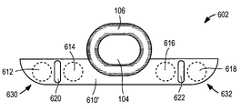
- FIG. 1is illustrates an electronic device 101 with a switch assembly in accordance with a first embodiment of the present invention.
- the electronic device 101may be any type of electronic device that requires the use of switches, for example, a PDA, a cellular telephone, a portable media player, a smartphone, a PDA phone, a mobile manager, a portable computer, etc.
- the electronic device 101includes a display 102 and a switch assembly 100 for navigating through the user interface and selecting certain items shown in the display 102 or activating certain applications of the electronic device 101 .
- the switch assemblyincludes a central switch 104 , a navigational ring switch 106 adjacent to and surrounding the central switch 104 , and two additional switches 108 , 109 adjacent to the navigation ring switch 104 and positioned on the left and right sides of the navigational ring switch 106 .
- the central switch 104is typically used to select or activate applications or other items of the electronic device 101 , although the central switch 104 can be used for other functions.
- the navigational ring switch 106includes four switches corresponding to 4 directions (up 151 , down 152 , left 153 , and right 154 ), and is typically used to navigate through the user interface shown on the display 102 in one embodiment, although the ring switch 106 may be used for other functions such as selecting or activating certain items or applications.
- the ring switch 106has an elliptical shape in FIG. 1 , but can also have other shapes such as a circular shape, a square shape, a rectangular shape, or a diamond shape, in other embodiments.
- the two switches 108 , 109are typically used to select or activate certain applications or items of the electronic device 101 .
- a number of functions of the electronic device 101can be integrated into the switch assembly 100 in a compact and convenient manner.
- the switches 108 , 109include activation areas 110 , 111 having a concave surface in one embodiment.
- the activation areas 110 , 111can have convex surfaces or “divots” (e.g., a plurality of tiny concave or convex surfaces), or other types of non-smooth surfaces such that its texture differs from the texture of adjacent surface areas outside the activation area.
- the activation areas 110 , 111correspond to the location of the switch mechanics underlying the switches 110 , 111 , and make it easier for a user to feel and locate where the switches 110 , 111 are and where to touch in order to activate the switches 110 , 111 .
- the switches 104 , 106 , 108 , 109form a non-planar surface with respect to each other, such that one may easily feel that one's finger is moving from one part of the switch to another part of the switch just by tactile contact with the switches 104 , 106 , 108 , 109 , as will be explained in greater detail with reference to FIG. 2 .
- the central switch 104may have a concave surface
- the navigational ring switch 106may have a convex surface
- the switches 108 , 109may have concave activation areas 110 , 111 with flat surfaces outside the activation areas 110 , 111 .
- the central switch 104may have a concave surface
- the navigational ring switch 106may have a convex surface
- the switches 108 , 109may have convex activation areas 110 , 111 with flat surfaces outside the activation areas 110 , 111 .
- the central switch 104may have a convex surface
- the navigational ring switch 106may have a concave surface
- the switches 108 , 109may have concave activation areas 110 , 111 and flat surfaces outside the activation areas 110 , 111 .
- the central switch 104may have a convex surface
- the navigational ring switch 106may have a concave surface
- the switches 108 , 109may have convex activation areas 110 , 111 and flat surfaces outside the activation areas 110 , 111 .
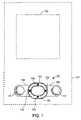
- FIG. 2is illustrates the structure of the switch assembly 100 of FIG. 1 in greater detail, in accordance with the first embodiment of the present invention.
- the line 200illustrates the contour of the surface of the switch assembly 100 along lines A-A′ of the switch assembly 100 in FIG. 2 .
- the central switch 104has a concave surface 202
- the navigational ring switch 106has a convex surface 204 , 206
- the switches 108 , 109have mostly flat (planar) surfaces 208 , 210 , 212 , 214 outside the activation areas 110 , 111 with the activation areas 110 , 111 having concave surfaces 216 , 218 .
- Such non-planar surfacemakes it easy for the switch assembly 100 to be used. For example, one may center his thumb or other finger in the concavity 202 of the central switch 104 to select the central switch 104 .
- the navigational ring switch 106it is easy to feel where the navigational ring switch 106 is located because the navigational ring switch 106 has a convex surface 204 , 206 in contrast to the concave surface 202 of the central switch 104 ; by sliding one's finger over from the central switch 104 to the navigational ring switch 106 , one gets tactile feedback that the finger moved to another switch or control area.
- switches 108 , 109 and their activation areas 110 , 111are located, because the switches 108 , 109 have flat (planar) surfaces 208 , 210 , 212 , 214 and their activation areas 110 , 111 have concave surfaces 216 , 218 in contrast to the convex surface 204 , 206 of the navigational ring switch 106 ; by sliding one's finger over from the navigational ring switch 106 to the switches 108 , 109 and especially their concave activation areas 110 , 111 , one gets tactile feedback that the finger moved to another switch or control area.
- the switches 104 , 106 , 108 , 109are connected to corresponding switch mechanics.
- the switches 104 , 106 , 108 , and 109may be any type of switch, e.g., a dome switch, a microswitch, or a touch panel, and include the appropriate switch mechanics (not shown) corresponding to the type of the switch.
- FIG. 3illustrates a personal digital assistant (PDA) type electronic device 101 including a switch assembly 100 in accordance with the first embodiment of the present invention.
- the navigational ring switch 106is configured (by software) to navigate through the items 302 in the user interface shown on the display 102 of the device 101 .
- the central switch 104is configured to select a particular item 304 when activated.
- the additional switches 108 , 109are configured to launch or activate certain applications of the electronic device 101 when activated. For example, a calendar application may be launched if the activation area 110 of the switch 108 is pressed, and an address book application may be launched if the activation area 111 of the switch 109 is pressed.
- switches 104 , 106 , 108 , 109are not limited to what is described herein, and that the switches 104 , 106 , 108 , 109 may be associated any other function as necessary for the electronic device 101 .
- the switches 104 , 106 , 108 , 109can be configured to provide different functions for different applications executing an electronic device. Alternatively, these switches can also be configured or programmed through the device to perform specific functions.
- FIG. 4Aillustrates a switch assembly in accordance with a second embodiment of the present invention.
- the switch assembly of FIG. 4Ais functionally identical to the switch assembly 100 shown in FIGS. 1-3 , but structurally differs by integrating the switches 402 , 406 , 412 , 416 .
- the switch assemblyis comprised of a concave central switch 104 , a convex navigational ring switch 106 , and four additional switches 402 , 406 , 412 , 416 .
- Two switches 402 , 406are located on the left side of the navigational ring switch 106
- the other two switches 412 , 416are located on the right side of the navigational ring switch 106 .
- Each of the switches 402 , 406 , 412 , 416has a flat (planar) surface with a concave activation area 404 , 408 , 410 , 414 , respectively.
- the second embodiment shown in FIG. 4Amakes it possible to have additional (at least 4) functions associated with the switches 402 , 406 , 412 , 416 without occupying a lot of space.
- the four additional switches 402 , 406 , 412 , 416each have smooth triangular-like shapes.
- the first leg 413 of the switch 416tracks along a perimeter of the navigational ring switch 106
- the length of the second leg 415 of the switch 416tracks along the length of the second leg 419 of the adjacent switch 412
- the third leg 417 of the switch 416provides a rounded edge that roughly tracks along the edge of the navigational ring switch 106 .
- the other switches 402 , 406 , 412are all configured in a similar fashion.
- the overall configurationas illustrated, provides an elegant design, e.g., a flowing elliptical design, while maintaining or increasing functionality and user friendliness.
- FIG. 4Billustrates a switch assembly in accordance with a third embodiment of the present invention.
- the switch assembly of FIG. 4Bis functionally identical to the switch assembly 100 shown in FIGS. 1-3 , but structurally differs by integrating the additional switches 418 , 422 , 426 , 430 .
- the switch assemblyis comprised of a concave central switch 104 , a convex navigational ring switch 106 , and four additional switches 418 , 422 , 426 , 430 .
- the switch 418is located on the upper side of the navigational ring switch 106
- the switch 422is located on the left side of the navigational ring switch 106
- the switch 426is located on the lower side of the navigational ring switch 106
- the switch 430is located on the right side of the navigational ring switch 106 .
- Each of the switches 418 , 422 , 426 , 430has a flat (planar) surface with a concave activation area 420 , 424 , 428 , 432 , respectively.
- the third embodiment shown in FIG. 4Bmakes it possible to have additional (at least 4 ) functions associated with the switches 402 , 406 , 412 , 416 in a compact and symmetrical manner without occupying a lot of space.
- FIG. 4Cillustrates a switch assembly in accordance with a fourth embodiment of the present invention.
- the switch assembly of FIG. 4Cis functionally identical to the switch assembly 100 shown in FIGS. 1-3 , but structurally differs by integrating the eight additional switches 450 , 454 , 458 , 462 , 466 , 470 , 474 , 478 .
- this configurationalso provides a navigational region in which buttons are structurally configured in close proximity, e.g., adjacent, but also includes surface or texture differences that allow easy distinguishing between them.
- buttonsare structurally configured in close proximity, e.g., adjacent, but also includes surface or texture differences that allow easy distinguishing between them.
- the switch assemblyis comprised of a concave central switch 104 , a convex navigational ring switch 106 , and eight additional switches 450 , 454 , 458 , 462 , 466 , 470 , 474 , 478 .
- the switch 450is located on the upper side of the navigational ring switch 106
- the switch 458is located on the left side of the navigational ring switch 106
- the switch 466is located on the lower side of the navigational ring switch 106
- the switch 474is located on the right side of the navigational ring switch 106
- the switch 454is located between the switches 450 , 458
- the switch 462is located between the switches 458 , 466
- the switch 470is located between the switches 466 , 474
- the switch 478is located between the switches 450 , 474 .
- Each of the switches 450 , 454 , 458 , 462 , 466 , 470 , 474 , 478has a flat (planar) surface with a concave activation area 452 , 456 , 460 , 464 , 468 , 472 , 476 , 480 , respectively.
- the fourth embodiment shown in FIG. 4Cmakes it possible to have a number of additional (at least 8) functions associated with the switches 450 , 454 , 458 , 462 , 466 , 470 , 474 , 478 in a compact and symmetrical manner without occupying a lot of space.
- FIG. 5illustrates switch assemblies 500 , 502 , 504 in accordance with a fifth embodiment of the present invention.
- the switch assembly 500is functionally identical to the switch assembly 100 shown in FIGS. 1-3 , but structurally differs by integrating two switch regions 510 , 512 enclosing the navigational ring switch 106 .
- the switch region 510includes two concave activation areas 514 , 518
- the switch region 512includes two concave activation areas 516 , 520 .
- the switch assembly 502is identical to the switch assembly 500 , except that it has smoother edges at the outer corners 530 , 532 , 534 , 536 of the switch regions 510 ′, 512 ′.
- the switch assembly 504is identical to the switch assembly 500 except that it has even smoother (almost round) edges at the outer corners 538 , 539 , 540 , 542 of the switch regions 510 ′′, 512 ′′.
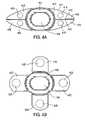
- FIG. 6illustrates switch assemblies 600 , 602 in accordance with a sixth embodiment of the present invention.
- the switch assembly 602is functionally identical to the switch assembly 100 shown in FIGS. 1-3 , but structurally differs by integrating a switch region 610 enclosing a bottom half of the navigational ring switch 106 .
- the switch region 610includes four concave activation areas 612 , 614 , 616 , 618 , where two of the activation areas 612 , 614 are separated by a convex divider 620 , and the other two of the activation areas 616 , 618 are separated by another convex divider 622 .
- the convex dividers 620 , 622serve as “speed bumps” such that one can tactically feel and distinguish between two activation areas 612 , 614 or 616 , 168 that are positioned close to each other.
- the switch region 610encloses only the bottom half of the navigational ring switch 106 in the example of FIG. 6
- the switch region 610can be modified to enclose the upper half or the entire navigational ring switch 106 .
- the switch region 610includes only 4 activation areas 612 , 614 , 616 , 618 in the example of FIG. 6
- the switch region 610can include any number of activation areas where two or more of the activation areas are divided by a divider.
- the switch assembly 602is identical to the switch assembly 600 , except that the switch region 610 ′ has smoother edges 630 , 632 .
Landscapes
- Engineering & Computer Science (AREA)
- Theoretical Computer Science (AREA)
- Computer Hardware Design (AREA)
- Human Computer Interaction (AREA)
- Physics & Mathematics (AREA)
- General Engineering & Computer Science (AREA)
- General Physics & Mathematics (AREA)
- Push-Button Switches (AREA)
- Input From Keyboards Or The Like (AREA)
Abstract
Description
Claims (29)
Priority Applications (2)
| Application Number | Priority Date | Filing Date | Title |
|---|---|---|---|
| US11/241,199US7569781B2 (en) | 2005-09-30 | 2005-09-30 | Switch assembly having non-planar surface and activation areas |
| PCT/US2006/035088WO2007040911A2 (en) | 2005-09-30 | 2006-09-08 | Switch assembly having non-planar surface and activation areas |
Applications Claiming Priority (1)
| Application Number | Priority Date | Filing Date | Title |
|---|---|---|---|
| US11/241,199US7569781B2 (en) | 2005-09-30 | 2005-09-30 | Switch assembly having non-planar surface and activation areas |
Publications (2)
| Publication Number | Publication Date |
|---|---|
| US20070074957A1 US20070074957A1 (en) | 2007-04-05 |
| US7569781B2true US7569781B2 (en) | 2009-08-04 |
Family
ID=37900845
Family Applications (1)
| Application Number | Title | Priority Date | Filing Date |
|---|---|---|---|
| US11/241,199Expired - Fee RelatedUS7569781B2 (en) | 2005-09-30 | 2005-09-30 | Switch assembly having non-planar surface and activation areas |
Country Status (2)
| Country | Link |
|---|---|
| US (1) | US7569781B2 (en) |
| WO (1) | WO2007040911A2 (en) |
Cited By (4)
| Publication number | Priority date | Publication date | Assignee | Title |
|---|---|---|---|---|
| US20080119249A1 (en)* | 2006-11-17 | 2008-05-22 | Lg Electronics Inc. | Sliding type mobile terminal |
| US20080139259A1 (en)* | 2006-11-17 | 2008-06-12 | Lg Electronics Inc. | Folding type mobile terminal |
| USD624908S1 (en)* | 2009-11-05 | 2010-10-05 | Reminderband, Inc. | Case |
| US7953448B2 (en)* | 2006-05-31 | 2011-05-31 | Research In Motion Limited | Keyboard for mobile device |
Families Citing this family (17)
| Publication number | Priority date | Publication date | Assignee | Title |
|---|---|---|---|---|
| US6388877B1 (en)* | 1999-02-04 | 2002-05-14 | Palm, Inc. | Handheld computer with open accessory slot |
| US20070081303A1 (en)* | 2005-10-11 | 2007-04-12 | Lawrence Lam | Recess housing feature for computing devices |
| USD600245S1 (en) | 2005-10-11 | 2009-09-15 | Palm, Inc. | Computing device |
| USD621392S1 (en) | 2007-02-28 | 2010-08-10 | Palm, Inc. | Mobile computing device having a navigation button combination |
| USD596629S1 (en) | 2007-02-28 | 2009-07-21 | Palm, Inc. | Set of buttons for a mobile computing device |
| USD572715S1 (en)* | 2007-03-06 | 2008-07-08 | Palm, Inc. | Set of buttons for a mobile computing device |
| USD590817S1 (en) | 2007-03-06 | 2009-04-21 | Palm, Inc. | Button for a mobile computing device |
| USD617330S1 (en) | 2007-03-06 | 2010-06-08 | Palm, Inc. | Mobile computing device |
| USD588603S1 (en) | 2007-07-26 | 2009-03-17 | Palm, Inc. | Set of buttons for a mobile computing device |
| US8270158B2 (en)* | 2007-08-30 | 2012-09-18 | Hewlett-Packard Development Company, L.P. | Housing construction for mobile computing device |
| USD613743S1 (en) | 2007-08-30 | 2010-04-13 | Palm, Inc. | Mobile computing device |
| US20090058812A1 (en)* | 2007-08-30 | 2009-03-05 | Yoshimichi Matsuoka | Mobile computing device construction using front paneled assembly and components thereof |
| USD620917S1 (en)* | 2007-12-26 | 2010-08-03 | Aiphone Co., Ltd. | Interphone |
| US20110193787A1 (en)* | 2010-02-10 | 2011-08-11 | Kevin Morishige | Input mechanism for providing dynamically protruding surfaces for user interaction |
| US8385057B2 (en) | 2010-06-08 | 2013-02-26 | Hewlett-Packard Development Company, L.P. | Fully extendable dual-segmented housing assembly for mobile computing device |
| USD688652S1 (en)* | 2012-09-27 | 2013-08-27 | Nokia Corporation | Handset keys |
| EP4231867A1 (en)* | 2020-10-23 | 2023-08-30 | JT International SA | Aerosol generating device with biometric identification |
Citations (37)
| Publication number | Priority date | Publication date | Assignee | Title |
|---|---|---|---|---|
| USD288746S (en) | 1984-03-12 | 1987-03-17 | Heinz Allekotte | Frame |
| USD306176S (en) | 1986-02-25 | 1990-02-20 | Sharp Corporation | Combined calculator and cradle therefor |
| US5398310A (en) | 1992-04-13 | 1995-03-14 | Apple Computer, Incorporated | Pointing gesture based computer note pad paging and scrolling interface |
| USD366220S (en) | 1995-03-24 | 1996-01-16 | Matsushita Electric Industrial Co., Ltd. | Handheld position detecting and indicating receiver |
| US5528235A (en)* | 1991-09-03 | 1996-06-18 | Edward D. Lin | Multi-status multi-function data processing key and key array |
| USD410440S (en) | 1998-05-28 | 1999-06-01 | Charles F Carnell | Vehicle maintenance manager |
| USD424535S (en) | 1999-06-02 | 2000-05-09 | Oy Hi-Log Instruments Ltd. | Data terminal for replies from customers |
| US6310609B1 (en) | 1997-04-17 | 2001-10-30 | Nokia Mobile Phones Limited | User interface with guide lights |
| USD456289S1 (en) | 2001-07-05 | 2002-04-30 | Garmin Ltd. | Electronic navigation instrument |
| USD456794S1 (en) | 2001-08-30 | 2002-05-07 | Garmin Ltd. | Wireless communications device |
| US6437682B1 (en)* | 2000-04-20 | 2002-08-20 | Ericsson Inc. | Pressure sensitive direction switches |
| US20020151283A1 (en)* | 2001-04-02 | 2002-10-17 | Pallakoff Matthew G. | Coordinating images displayed on devices with two or more displays |
| USD466504S1 (en) | 2001-06-19 | 2002-12-03 | Nec Corporation | Portable wireless terminal equipment |
| USD467918S1 (en) | 2001-04-24 | 2002-12-31 | Hand Held Products, Inc. | Data collection device |
| USD468714S1 (en) | 2002-02-04 | 2003-01-14 | Motorola, Inc. | Housing for a communication device or similar articles |
| USD469061S1 (en) | 2002-02-19 | 2003-01-21 | Arthur James Porter | Key chain mountable battery holder in the shape of a generic personal digital assistant |
| US6563061B2 (en)* | 2000-04-28 | 2003-05-13 | Fujitsu Takamisawa Component Limited | Key switch and keyboard |
| USD488162S1 (en) | 2003-05-12 | 2004-04-06 | James Korpai | Screen border |
| US6744423B2 (en)* | 2001-11-19 | 2004-06-01 | Nokia Corporation | Communication terminal having a predictive character editor application |
| US20040140190A1 (en)* | 2002-08-09 | 2004-07-22 | Searle Gary M. | Switch assembly and method of guiding a push button switch in a switch housing |
| USD502703S1 (en) | 2004-04-05 | 2005-03-08 | Sharp Kabushiki Kaisha | Personal digital assistant |
| WO2005024616A1 (en)* | 2003-09-04 | 2005-03-17 | Matsushita Electric Industrial Co., Ltd. | Electronic device, input device, and portable electronic device using the same |
| US6911608B2 (en)* | 2002-05-23 | 2005-06-28 | Digit Wireless, Llc | Keypads and key switches |
| US20050174260A1 (en)* | 2004-02-10 | 2005-08-11 | Arneson Theodore R. | Electronic device with force sensing key |
| US6933927B2 (en)* | 2001-12-06 | 2005-08-23 | Asustek Computer Inc. | Button key structure integrated with a speaker |
| US6956180B1 (en)* | 2004-10-22 | 2005-10-18 | Universal Scientific Industrial Co., Ltd. | Watertight key unit for an electronic device |
| USD511342S1 (en) | 2004-08-04 | 2005-11-08 | High Tech Computer, Corp. | Handheld electronic device |
| US6963039B1 (en)* | 2004-12-22 | 2005-11-08 | Inventec Multimedia & Telecom Corporation | Button knob waterproofing design |
| US20050264988A1 (en) | 2004-05-26 | 2005-12-01 | Nicolosi Matthew T | Slide case with pivotable stand member for handheld computing device |
| US7113111B2 (en)* | 2004-02-26 | 2006-09-26 | Research In Motion Limited | Keyboard arrangement for handheld electronic devices |
| USD530698S1 (en) | 2005-04-27 | 2006-10-24 | Samsung Electronics Co., Ltd. | Mobile phone |
| USD532440S1 (en) | 2005-05-06 | 2006-11-21 | Calibre International, Llc | Calculator |
| US20060265643A1 (en) | 2005-05-17 | 2006-11-23 | Keith Saft | Optimal viewing of digital images and voice annotation transitions in slideshows |
| US20070081303A1 (en) | 2005-10-11 | 2007-04-12 | Lawrence Lam | Recess housing feature for computing devices |
| US7205959B2 (en) | 2003-09-09 | 2007-04-17 | Sony Ericsson Mobile Communications Ab | Multi-layered displays providing different focal lengths with optically shiftable viewing formats and terminals incorporating the same |
| US7231208B2 (en) | 2001-10-17 | 2007-06-12 | Palm, Inc. | User interface-technique for managing an active call |
| USD548732S1 (en) | 2005-04-22 | 2007-08-14 | Palm, Inc. | Front panel of a housing for a portable computing device |
- 2005
- 2005-09-30USUS11/241,199patent/US7569781B2/ennot_activeExpired - Fee Related
- 2006
- 2006-09-08WOPCT/US2006/035088patent/WO2007040911A2/enactiveApplication Filing
Patent Citations (39)
| Publication number | Priority date | Publication date | Assignee | Title |
|---|---|---|---|---|
| USD288746S (en) | 1984-03-12 | 1987-03-17 | Heinz Allekotte | Frame |
| USD306176S (en) | 1986-02-25 | 1990-02-20 | Sharp Corporation | Combined calculator and cradle therefor |
| US5528235A (en)* | 1991-09-03 | 1996-06-18 | Edward D. Lin | Multi-status multi-function data processing key and key array |
| US5398310A (en) | 1992-04-13 | 1995-03-14 | Apple Computer, Incorporated | Pointing gesture based computer note pad paging and scrolling interface |
| USD366220S (en) | 1995-03-24 | 1996-01-16 | Matsushita Electric Industrial Co., Ltd. | Handheld position detecting and indicating receiver |
| US6310609B1 (en) | 1997-04-17 | 2001-10-30 | Nokia Mobile Phones Limited | User interface with guide lights |
| USD410440S (en) | 1998-05-28 | 1999-06-01 | Charles F Carnell | Vehicle maintenance manager |
| USD424535S (en) | 1999-06-02 | 2000-05-09 | Oy Hi-Log Instruments Ltd. | Data terminal for replies from customers |
| US6437682B1 (en)* | 2000-04-20 | 2002-08-20 | Ericsson Inc. | Pressure sensitive direction switches |
| US6563061B2 (en)* | 2000-04-28 | 2003-05-13 | Fujitsu Takamisawa Component Limited | Key switch and keyboard |
| US7016704B2 (en)* | 2001-04-02 | 2006-03-21 | Move Mobile Systems, Inc. | Coordinating images displayed on devices with two or more displays |
| US20020151283A1 (en)* | 2001-04-02 | 2002-10-17 | Pallakoff Matthew G. | Coordinating images displayed on devices with two or more displays |
| USD467918S1 (en) | 2001-04-24 | 2002-12-31 | Hand Held Products, Inc. | Data collection device |
| USD466504S1 (en) | 2001-06-19 | 2002-12-03 | Nec Corporation | Portable wireless terminal equipment |
| USD456289S1 (en) | 2001-07-05 | 2002-04-30 | Garmin Ltd. | Electronic navigation instrument |
| USD456794S1 (en) | 2001-08-30 | 2002-05-07 | Garmin Ltd. | Wireless communications device |
| US7231208B2 (en) | 2001-10-17 | 2007-06-12 | Palm, Inc. | User interface-technique for managing an active call |
| US6744423B2 (en)* | 2001-11-19 | 2004-06-01 | Nokia Corporation | Communication terminal having a predictive character editor application |
| US6933927B2 (en)* | 2001-12-06 | 2005-08-23 | Asustek Computer Inc. | Button key structure integrated with a speaker |
| USD468714S1 (en) | 2002-02-04 | 2003-01-14 | Motorola, Inc. | Housing for a communication device or similar articles |
| USD469061S1 (en) | 2002-02-19 | 2003-01-21 | Arthur James Porter | Key chain mountable battery holder in the shape of a generic personal digital assistant |
| US6911608B2 (en)* | 2002-05-23 | 2005-06-28 | Digit Wireless, Llc | Keypads and key switches |
| US20040140190A1 (en)* | 2002-08-09 | 2004-07-22 | Searle Gary M. | Switch assembly and method of guiding a push button switch in a switch housing |
| USD488162S1 (en) | 2003-05-12 | 2004-04-06 | James Korpai | Screen border |
| WO2005024616A1 (en)* | 2003-09-04 | 2005-03-17 | Matsushita Electric Industrial Co., Ltd. | Electronic device, input device, and portable electronic device using the same |
| US20070037611A1 (en)* | 2003-09-04 | 2007-02-15 | Matshushita Electric Industrial Co., Ltd. | Electronic device, input device, and portable electronic device using the same |
| US7205959B2 (en) | 2003-09-09 | 2007-04-17 | Sony Ericsson Mobile Communications Ab | Multi-layered displays providing different focal lengths with optically shiftable viewing formats and terminals incorporating the same |
| US20050174260A1 (en)* | 2004-02-10 | 2005-08-11 | Arneson Theodore R. | Electronic device with force sensing key |
| US7113111B2 (en)* | 2004-02-26 | 2006-09-26 | Research In Motion Limited | Keyboard arrangement for handheld electronic devices |
| USD502703S1 (en) | 2004-04-05 | 2005-03-08 | Sharp Kabushiki Kaisha | Personal digital assistant |
| US20050264988A1 (en) | 2004-05-26 | 2005-12-01 | Nicolosi Matthew T | Slide case with pivotable stand member for handheld computing device |
| USD511342S1 (en) | 2004-08-04 | 2005-11-08 | High Tech Computer, Corp. | Handheld electronic device |
| US6956180B1 (en)* | 2004-10-22 | 2005-10-18 | Universal Scientific Industrial Co., Ltd. | Watertight key unit for an electronic device |
| US6963039B1 (en)* | 2004-12-22 | 2005-11-08 | Inventec Multimedia & Telecom Corporation | Button knob waterproofing design |
| USD548732S1 (en) | 2005-04-22 | 2007-08-14 | Palm, Inc. | Front panel of a housing for a portable computing device |
| USD530698S1 (en) | 2005-04-27 | 2006-10-24 | Samsung Electronics Co., Ltd. | Mobile phone |
| USD532440S1 (en) | 2005-05-06 | 2006-11-21 | Calibre International, Llc | Calculator |
| US20060265643A1 (en) | 2005-05-17 | 2006-11-23 | Keith Saft | Optimal viewing of digital images and voice annotation transitions in slideshows |
| US20070081303A1 (en) | 2005-10-11 | 2007-04-12 | Lawrence Lam | Recess housing feature for computing devices |
Non-Patent Citations (8)
| Title |
|---|
| Palm LifeDriveQuicktrain.qxd, Dec. 6, 2005, 3 pages. |
| Palm Treo 650, [online] [Retrieved on Jan. 4, 2006] Retrieved from the Internet<URL:http://www.palm.com/us/products/smartphones/treo650/details.epl>. |
| Palm Tungsten C, [online] [Retrieved on Jan. 4, 2006] Retrieved from the Internet<URL:http://www.palm.com/us/products/handhelds/tungsten-c/specs.epl>. |
| Palm Tungsten E2, [online] [Retrieved on Jan. 4, 2006] Retrieved from the Internet<URL:http://www.palm.com/us/products/handhelds/tungsten-e2/specs.epl>. |
| Palm Tungsten T5, [online] [Retrieved on Jan. 4, 2006] Retrieved from the Internet<URL:http//www.palm.com/us/products/handhelds/tungsten-t5/specs.epl>. |
| Palm Zire 31, [online] [Retrieved on Jan. 4, 2006] Retrieved from the Internet<URL:http://www.palm.com/us/products/handhelds/zire31/details.epl>. |
| Palm Zire 72, [online] [Retrieved on Jan. 4, 2006] Retrieved from the Internet<URL:http://www.palm.com/us/products/handhelds/zire72/details.epl>. |
| PCT International Search Report and Written Opinion, PCT/US06/35088, Apr. 24, 2007, 7 pages. |
Cited By (6)
| Publication number | Priority date | Publication date | Assignee | Title |
|---|---|---|---|---|
| US7953448B2 (en)* | 2006-05-31 | 2011-05-31 | Research In Motion Limited | Keyboard for mobile device |
| US20080119249A1 (en)* | 2006-11-17 | 2008-05-22 | Lg Electronics Inc. | Sliding type mobile terminal |
| US20080139259A1 (en)* | 2006-11-17 | 2008-06-12 | Lg Electronics Inc. | Folding type mobile terminal |
| US7869845B2 (en)* | 2006-11-17 | 2011-01-11 | Lg Electronics Inc. | Sliding type mobile terminal |
| US7912521B2 (en)* | 2006-11-17 | 2011-03-22 | Lg Electronics Inc. | Folding type mobile terminal |
| USD624908S1 (en)* | 2009-11-05 | 2010-10-05 | Reminderband, Inc. | Case |
Also Published As
| Publication number | Publication date |
|---|---|
| WO2007040911A3 (en) | 2007-06-28 |
| US20070074957A1 (en) | 2007-04-05 |
| WO2007040911A2 (en) | 2007-04-12 |
Similar Documents
| Publication | Publication Date | Title |
|---|---|---|
| WO2007040911A2 (en) | Switch assembly having non-planar surface and activation areas | |
| US8054614B2 (en) | Cover for device | |
| US9477320B2 (en) | Input device | |
| CN201392758Y (en) | Handheld wireless communication device | |
| US9541962B2 (en) | Mobile computing device having a flexible hinge structure | |
| US7907121B2 (en) | Portable device with versatile keyboard | |
| WO2010016409A1 (en) | Input apparatus, input method, and recording medium on which input program is recorded | |
| US8482528B2 (en) | Ultra mobile personal computer | |
| US20150335116A1 (en) | Protective case for mobile device | |
| US20090225056A1 (en) | User interface for mobile computing device | |
| WO2009084147A1 (en) | Portable terminal, display control method, and display control program | |
| AU2012296684A1 (en) | Wristwatch keyboard | |
| US20070159459A1 (en) | Omni-Directional Image Navigator | |
| US10387017B2 (en) | Electronic device for displaying multiple screens and control method therefor | |
| JPWO2013080448A1 (en) | Information processing device | |
| WO2006022383A1 (en) | Portable terminal | |
| EP1860527A2 (en) | Omni-directional image navigator | |
| US6948869B2 (en) | Compact ergonomic telephony keypad | |
| JP2009193279A (en) | Pointing device | |
| JP3989297B2 (en) | Small personal digital assistant | |
| JP3180086U (en) | Touch panel type small terminal operation tool | |
| KR20140048756A (en) | Operation method of personal portable device having touch panel | |
| JP4227943B2 (en) | Portable electronic devices | |
| US7359505B2 (en) | Space-efficient ergonomic telephony keypad | |
| US20110006989A1 (en) | Pointing Device |
Legal Events
| Date | Code | Title | Description |
|---|---|---|---|
| AS | Assignment | Owner name:PALM, INC., CALIFORNIA Free format text:ASSIGNMENT OF ASSIGNORS INTEREST;ASSIGNORS:LAM, LAWRENCE;CEBE, CHROME;REEL/FRAME:017294/0353 Effective date:20051108 | |
| AS | Assignment | Owner name:JPMORGAN CHASE BANK, N.A., NEW YORK Free format text:SECURITY AGREEMENT;ASSIGNOR:PALM, INC.;REEL/FRAME:020341/0285 Effective date:20071219 Owner name:JPMORGAN CHASE BANK, N.A.,NEW YORK Free format text:SECURITY AGREEMENT;ASSIGNOR:PALM, INC.;REEL/FRAME:020341/0285 Effective date:20071219 | |
| FEPP | Fee payment procedure | Free format text:PAYOR NUMBER ASSIGNED (ORIGINAL EVENT CODE: ASPN); ENTITY STATUS OF PATENT OWNER: LARGE ENTITY | |
| CC | Certificate of correction | ||
| AS | Assignment | Owner name:PALM, INC., CALIFORNIA Free format text:RELEASE BY SECURED PARTY;ASSIGNOR:JPMORGAN CHASE BANK, N.A., AS ADMINISTRATIVE AGENT;REEL/FRAME:024630/0474 Effective date:20100701 | |
| AS | Assignment | Owner name:HEWLETT-PACKARD DEVELOPMENT COMPANY, L.P., TEXAS Free format text:ASSIGNMENT OF ASSIGNORS INTEREST;ASSIGNOR:PALM, INC.;REEL/FRAME:025204/0809 Effective date:20101027 | |
| FPAY | Fee payment | Year of fee payment:4 | |
| AS | Assignment | Owner name:PALM, INC., CALIFORNIA Free format text:ASSIGNMENT OF ASSIGNORS INTEREST;ASSIGNOR:HEWLETT-PACKARD DEVELOPMENT COMPANY, L.P.;REEL/FRAME:030341/0459 Effective date:20130430 | |
| AS | Assignment | Owner name:HEWLETT-PACKARD DEVELOPMENT COMPANY, L.P., TEXAS Free format text:ASSIGNMENT OF ASSIGNORS INTEREST;ASSIGNOR:PALM, INC.;REEL/FRAME:031837/0659 Effective date:20131218 Owner name:PALM, INC., CALIFORNIA Free format text:ASSIGNMENT OF ASSIGNORS INTEREST;ASSIGNOR:HEWLETT-PACKARD DEVELOPMENT COMPANY, L.P.;REEL/FRAME:031837/0544 Effective date:20131218 Owner name:HEWLETT-PACKARD DEVELOPMENT COMPANY, L.P., TEXAS Free format text:ASSIGNMENT OF ASSIGNORS INTEREST;ASSIGNOR:PALM, INC.;REEL/FRAME:031837/0239 Effective date:20131218 | |
| AS | Assignment | Owner name:QUALCOMM INCORPORATED, CALIFORNIA Free format text:ASSIGNMENT OF ASSIGNORS INTEREST;ASSIGNORS:HEWLETT-PACKARD COMPANY;HEWLETT-PACKARD DEVELOPMENT COMPANY, L.P.;PALM, INC.;REEL/FRAME:032177/0210 Effective date:20140123 | |
| REMI | Maintenance fee reminder mailed | ||
| LAPS | Lapse for failure to pay maintenance fees | Free format text:PATENT EXPIRED FOR FAILURE TO PAY MAINTENANCE FEES (ORIGINAL EVENT CODE: EXP.) | |
| STCH | Information on status: patent discontinuation | Free format text:PATENT EXPIRED DUE TO NONPAYMENT OF MAINTENANCE FEES UNDER 37 CFR 1.362 | |
| FP | Lapsed due to failure to pay maintenance fee | Effective date:20170804 |