US7569066B2 - Methods and devices for the treatment of aneurysms - Google Patents
Methods and devices for the treatment of aneurysmsDownload PDFInfo
- Publication number
- US7569066B2 US7569066B2US10/369,015US36901503AUS7569066B2US 7569066 B2US7569066 B2US 7569066B2US 36901503 AUS36901503 AUS 36901503AUS 7569066 B2US7569066 B2US 7569066B2
- Authority
- US
- United States
- Prior art keywords
- aneurysm
- bridge
- clip
- tube
- elongate member
- Prior art date
- Legal status (The legal status is an assumption and is not a legal conclusion. Google has not performed a legal analysis and makes no representation as to the accuracy of the status listed.)
- Expired - Fee Related, expires
Links
Images


Classifications
- A—HUMAN NECESSITIES
- A61—MEDICAL OR VETERINARY SCIENCE; HYGIENE
- A61B—DIAGNOSIS; SURGERY; IDENTIFICATION
- A61B17/00—Surgical instruments, devices or methods
- A61B17/12—Surgical instruments, devices or methods for ligaturing or otherwise compressing tubular parts of the body, e.g. blood vessels or umbilical cord
- A61B17/12022—Occluding by internal devices, e.g. balloons or releasable wires
- A61B17/12099—Occluding by internal devices, e.g. balloons or releasable wires characterised by the location of the occluder
- A61B17/12109—Occluding by internal devices, e.g. balloons or releasable wires characterised by the location of the occluder in a blood vessel
- A61B17/12113—Occluding by internal devices, e.g. balloons or releasable wires characterised by the location of the occluder in a blood vessel within an aneurysm
- A—HUMAN NECESSITIES
- A61—MEDICAL OR VETERINARY SCIENCE; HYGIENE
- A61B—DIAGNOSIS; SURGERY; IDENTIFICATION
- A61B17/00—Surgical instruments, devices or methods
- A61B17/12—Surgical instruments, devices or methods for ligaturing or otherwise compressing tubular parts of the body, e.g. blood vessels or umbilical cord
- A61B17/12022—Occluding by internal devices, e.g. balloons or releasable wires
- A61B17/12027—Type of occlusion
- A61B17/12036—Type of occlusion partial occlusion
- A—HUMAN NECESSITIES
- A61—MEDICAL OR VETERINARY SCIENCE; HYGIENE
- A61B—DIAGNOSIS; SURGERY; IDENTIFICATION
- A61B17/00—Surgical instruments, devices or methods
- A61B17/12—Surgical instruments, devices or methods for ligaturing or otherwise compressing tubular parts of the body, e.g. blood vessels or umbilical cord
- A61B17/12022—Occluding by internal devices, e.g. balloons or releasable wires
- A61B17/12027—Type of occlusion
- A61B17/1204—Type of occlusion temporary occlusion
- A—HUMAN NECESSITIES
- A61—MEDICAL OR VETERINARY SCIENCE; HYGIENE
- A61B—DIAGNOSIS; SURGERY; IDENTIFICATION
- A61B17/00—Surgical instruments, devices or methods
- A61B17/12—Surgical instruments, devices or methods for ligaturing or otherwise compressing tubular parts of the body, e.g. blood vessels or umbilical cord
- A61B17/12022—Occluding by internal devices, e.g. balloons or releasable wires
- A61B17/12099—Occluding by internal devices, e.g. balloons or releasable wires characterised by the location of the occluder
- A61B17/12109—Occluding by internal devices, e.g. balloons or releasable wires characterised by the location of the occluder in a blood vessel
- A61B17/12113—Occluding by internal devices, e.g. balloons or releasable wires characterised by the location of the occluder in a blood vessel within an aneurysm
- A61B17/12118—Occluding by internal devices, e.g. balloons or releasable wires characterised by the location of the occluder in a blood vessel within an aneurysm for positioning in conjunction with a stent
- A—HUMAN NECESSITIES
- A61—MEDICAL OR VETERINARY SCIENCE; HYGIENE
- A61B—DIAGNOSIS; SURGERY; IDENTIFICATION
- A61B17/00—Surgical instruments, devices or methods
- A61B17/12—Surgical instruments, devices or methods for ligaturing or otherwise compressing tubular parts of the body, e.g. blood vessels or umbilical cord
- A61B17/12022—Occluding by internal devices, e.g. balloons or releasable wires
- A61B17/12131—Occluding by internal devices, e.g. balloons or releasable wires characterised by the type of occluding device
- A61B17/12168—Occluding by internal devices, e.g. balloons or releasable wires characterised by the type of occluding device having a mesh structure
- A61B17/12172—Occluding by internal devices, e.g. balloons or releasable wires characterised by the type of occluding device having a mesh structure having a pre-set deployed three-dimensional shape
- A—HUMAN NECESSITIES
- A61—MEDICAL OR VETERINARY SCIENCE; HYGIENE
- A61B—DIAGNOSIS; SURGERY; IDENTIFICATION
- A61B17/00—Surgical instruments, devices or methods
- A61B17/12—Surgical instruments, devices or methods for ligaturing or otherwise compressing tubular parts of the body, e.g. blood vessels or umbilical cord
- A61B17/12022—Occluding by internal devices, e.g. balloons or releasable wires
- A61B17/12131—Occluding by internal devices, e.g. balloons or releasable wires characterised by the type of occluding device
- A61B17/12181—Occluding by internal devices, e.g. balloons or releasable wires characterised by the type of occluding device formed by fluidized, gelatinous or cellular remodelable materials, e.g. embolic liquids, foams or extracellular matrices
- A61B17/12186—Occluding by internal devices, e.g. balloons or releasable wires characterised by the type of occluding device formed by fluidized, gelatinous or cellular remodelable materials, e.g. embolic liquids, foams or extracellular matrices liquid materials adapted to be injected
- A—HUMAN NECESSITIES
- A61—MEDICAL OR VETERINARY SCIENCE; HYGIENE
- A61B—DIAGNOSIS; SURGERY; IDENTIFICATION
- A61B17/00—Surgical instruments, devices or methods
- A61B17/0057—Implements for plugging an opening in the wall of a hollow or tubular organ, e.g. for sealing a vessel puncture or closing a cardiac septal defect
- A—HUMAN NECESSITIES
- A61—MEDICAL OR VETERINARY SCIENCE; HYGIENE
- A61B—DIAGNOSIS; SURGERY; IDENTIFICATION
- A61B17/00—Surgical instruments, devices or methods
- A61B2017/00831—Material properties
- A61B2017/00867—Material properties shape memory effect
- A—HUMAN NECESSITIES
- A61—MEDICAL OR VETERINARY SCIENCE; HYGIENE
- A61B—DIAGNOSIS; SURGERY; IDENTIFICATION
- A61B17/00—Surgical instruments, devices or methods
- A61B17/12—Surgical instruments, devices or methods for ligaturing or otherwise compressing tubular parts of the body, e.g. blood vessels or umbilical cord
- A61B17/12022—Occluding by internal devices, e.g. balloons or releasable wires
- A61B2017/1205—Introduction devices
- A61B2017/12054—Details concerning the detachment of the occluding device from the introduction device
- A61B2017/12063—Details concerning the detachment of the occluding device from the introduction device electrolytically detachable
- A—HUMAN NECESSITIES
- A61—MEDICAL OR VETERINARY SCIENCE; HYGIENE
- A61B—DIAGNOSIS; SURGERY; IDENTIFICATION
- A61B90/00—Instruments, implements or accessories specially adapted for surgery or diagnosis and not covered by any of the groups A61B1/00 - A61B50/00, e.g. for luxation treatment or for protecting wound edges
- A61B90/06—Measuring instruments not otherwise provided for
- A61B2090/064—Measuring instruments not otherwise provided for for measuring force, pressure or mechanical tension
- A61B2090/065—Measuring instruments not otherwise provided for for measuring force, pressure or mechanical tension for measuring contact or contact pressure
- A—HUMAN NECESSITIES
- A61—MEDICAL OR VETERINARY SCIENCE; HYGIENE
- A61B—DIAGNOSIS; SURGERY; IDENTIFICATION
- A61B90/00—Instruments, implements or accessories specially adapted for surgery or diagnosis and not covered by any of the groups A61B1/00 - A61B50/00, e.g. for luxation treatment or for protecting wound edges
- A61B90/39—Markers, e.g. radio-opaque or breast lesions markers
Definitions
- the present inventiongenerally pertains to devices for treating aneurysms. More specifically, the present invention pertains to occlusion systems for the treatment of aneurysms.
- open craniotomyis a procedure by which an aneurysm is located, and treated, extravascularly.
- This type of procedurehas significant disadvantages.
- the patient undergoing open craniotomymust undergo general anesthesia.
- the patientundergoes a great deal of trauma in the area of the aneurysm by virtue of the fact that the surgeon must sever various tissues in order to reach the aneurysm.
- the surgeonIn treating cerebral aneurysms extravascularly, for instances, the surgeon must typically remove a portion of the patient's skull, and must also traumatize brain tissue in order to reach the aneurysm.
- embolic materialincludes, for example, detachable coils or an embolic agent, such as a liquid polymer.
- the injection of these types of embolic materialssuffer from disadvantages, most of which are associated with migration of the embolic material out of the aneurysm into the parent artery. This can cause permanent and irreversible occlusion of the parent artery.
- the detachable coilswhen detachable coils are used to occlude an aneurysm which does not have a well defined neck region, the detachable coils can migrate out of the sac of the aneurysm and into the parent artery. Further, it is, at times, difficult to gauge exactly how full the sac of the aneurysm is when detachable coils are being injected. Therefore, there is a risk of overfilling the aneurysm in which case the detachable coils also spill out into the parent artery.
- detachable coilsinvolves coil compaction over time. After filling the aneurysm, there remains space between the coils. Continued hemodynamic forces from the circulation act to compact the coil mass resulting in a cavity in the aneurysm neck. Thus, the aneurysm can recanalize.
- Embolic agent migrationis also a problem. For instance, where a liquid polymer is injected into the sac of the aneurysm, it can migrate out of the sac of the aneurysm due to the hemodynamics of the system. This can also lead to irreversible occlusion of the parent vessel.
- Some such techniquestypically involve temporarily occluding the parent vessel proximal of the aneurysm, so that no blood flow occurs through the parent vessel, until a thrombotic mass has formed in the sac of the aneurysm which helps reduce the tendency of the embolic material to migrate out of the aneurysm sac.
- thrombotic masscan dissolve through normal lysis of blood.
- it is highly undesirable to occlude the parent vessel even temporarily. Therefore, this techniqueis, at times, not available as a treatment option.
- even occluding the parent vesselmay not prevent all embolic material migration into the parent vessel.
- detachable balloonsAnother endovascular technique for treating aneurysms involves inserting a detachable balloon into the sac of the aneurysm using a microcatheter.
- the detachable balloonis then inflated using saline and/or contrast fluid.
- the balloonis then detached from the microcatheter and left within the sac of the aneurysm in an attempt to fill the sac of the aneurysm.
- detachable balloonsalso suffer disadvantages.
- detachable balloonswhen inflated, typically will not conform to the interior configuration of the aneurysm sac. Instead, the detachable balloon requires the aneurysm sac to conform to the exterior surface of the detachable balloon.
- detachable balloonscan rupture and migrate out of the aneurysm.
- One embodiment of the present inventionpertains to a device for at least partially occluding an aneurysm.
- the deviceincludes a first elongate member having a distal end.
- a bridgeis positioned proximate the distal end and transformable between a delivery configuration and a deployed configuration.
- a second elongate memberis movable relative to the first elongate member, the first and second elongate members being configured such that one can be moved relative to the other in order to transform the bridge between the delivery and deployed configurations.
- the devicecomprises a first elongate member with a proximal end, a distal end and an elongated length therebetween.
- a clip assemblyis attached proximate to the distal end of the first elongate member.
- the clipis moveable between a first position and a second position.
- the devicefurther comprises a bridge positioned proximate to the clip assembly. The bridge is expandable between a delivery configuration, wherein the clip is in the first position, and a deployed configuration, wherein the clip is in the second position.
- the devicecomprises a first elongate member having a proximal end and a distal end with an elongated length therebetween.
- An aneurysm neck bridgeis releasably connected to the distal end of the first elongate member at a connection point.
- the aneurysm neck bridgehas a proximal end and a distal end, and includes a first array having a deployed configuration and a delivery configuration.
- the first arrayis formed proximate the distal end of the aneurysm neck bridge.
- the aneurysm neck bridgefurther comprises a second array having a deployed configuration and a delivery configuration.
- the second arrayis formed proximate the proximal end of the aneurysm neck bridge.
- Yet another embodiment of the present inventionpertains to a method of at least partially occluding an aneurysm having a neck.
- the methodincludes the step of providing a device to occlude the aneurysm, the device having a two array bridge having a delivery configuration and a deployed configuration. Further, the method includes inserting the device into a parent vessel, and navigating the device to the neck of the aneurysm. The method further includes deploying the first array of the bridge inside the aneurysm, and deploying the second array of the bridge outside the aneurysm. The two array bridge is detached at the connection point. The method also provides for optionally delivering coils or other material to fill the inside of the aneurysm.
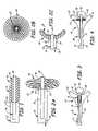
- FIG. 1is a side view of a portion of a neck occlusion device in accordance with the present invention.
- FIGS. 2A and 2Bare side and end views, respectively, of the neck occlusion device shown in FIG. 1 in an expanded position.
- FIG. 2Cis a side view of the device shown in FIG. 2A in an expanded position.
- FIGS. 3-7illustrate the deployment of the neck occlusion device shown in FIGS. 1 , 2 A and 2 B during treatment of an aneurysm.
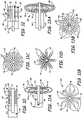
- FIG. 8illustrates a second embodiment of the neck occlusion device in accordance with the present invention.
- FIG. 9illustrates yet another embodiment of a neck occlusion device in accordance with the present invention.
- FIGS. 10-11Dillustrate two additional embodiments of a neck occlusion device in accordance with the present invention.
- FIGS. 12-13Billustrate yet another embodiment of a neck occlusion device in accordance with the present invention.
- FIGS. 14A-14Iillustrate additional embodiments of neck occlusion devices in accordance with the present invention.
- FIGS. 15A and 15Billustrate yet another embodiment of a neck occlusion device in accordance with the present invention.
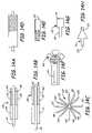
- FIGS. 16A-16Dillustrate yet another embodiment of a neck occlusion device in accordance with the present invention.
- FIG. 17illustrates yet another embodiment of a neck occlusion device in accordance with the present invention.
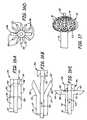
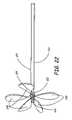
- FIG. 18is a side view of a wide neck multi span bridge.
- FIG. 19is a side view of a clip assembly.
- FIG. 20is a side view of an elongate member that includes the clip assembly of FIG. 19 .
- FIG. 21is an enlarged view of a portion of the elongate member shown in FIG. 20 in combination with a delivery tube and the multi span bridge of FIG. 18 .
- FIG. 22is a side view of the multi span bridge of FIG. 23 in a deployed configuration.
- FIG. 23is a diagrammatic view that shows the multi span bridge of FIG. 21 deployed in an aneurysm.
- FIG. 24is a profile view of a two basket aneurysm neck bridge between a delivery configuration, and a deployed configuration.
- FIGS. 24-1 to 24 - 5are schematic illustrations that show an expansion of a portion of the two basket aneurysm neck bridge from a collapsed configuration to a deployed configuration.
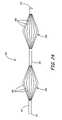
- FIG. 25is a profile view of the two basket aneurysm neck bridge in a deployed configuration.
- FIG. 26is a diagrammatic view that shows a microcatheter and the two basket aneurysm neck bridge in the delivery configuration.
- FIGS. 27-1 through 27 - 3are schematic illustrations that show deployment of the two basket bridge in an aneurysm.
- FIG. 1is a side view of a portion of a neck occlusion device 10 in accordance with the present invention.
- Device 10includes outer tubular member 12 , inner-tubular member 14 , and mesh portion 16 .
- Tubes 12 and 14are preferably coaxially arranged relative to one another, and are longitudinally slidable relative to one another.
- Mesh portion 16is attached, at its distal end 18 , to a distal portion 20 of inner tubular member 14 .
- Mesh 16is attached at its proximal end 22 to a distal portion 24 of outer tubular member 12 .
- Mesh portion 16is preferably formed of braided or woven filaments or fibers which are relatively flexible. Therefore, when tubes 12 and 14 are moved relative to one another, mesh portion 16 is deployed radially outwardly relative to the tubes 12 and 14 . This is illustrated by FIG. 2A .
- FIG. 2Ashows similar items to those shown in FIG. 1 , and they are similarly numbered.
- inner tube 14has been retracted in the direction indicated by arrow 26 relative to outer tube 12 .
- Thiscauses the distal end 20 of inner tube 14 to approach the distal end 24 of outer tube 12 .
- Thisalso, consequently, causes the central portion of mesh 16 to deploy radially outwardly relative to the two tubular members 12 and 14 to form a substantially disk-shaped (or dish-shaped) configuration.
- a pull wirecan be alternatively implemented in place of tube 14 .
- FIG. 2Bis an end view of device 10 in the deployed position shown in FIG. 2A .
- FIG. 2Balso shows that mesh portion 16 is relatively porous. This has advantages discussed with respect to FIGS. 3-7 .
- FIG. 2Cillustrates device 10 with inner tube 14 even further retracted in the direction indicated by arrow 26 relative to outer tube 12 .
- the present inventioncontemplates deployment of device 10 in this shape as well as in the other deployed shapes discussed herein.
- FIGS. 3-7illustrate the deployment of device 10 in treating an aneurysm.
- FIG. 3shows a blood vessel 28 having a main lumen 30 which bifurcates into two branch lumens 32 and 34 which communicate with lumen 30 .
- aneurysm 36has formed in the vessel wall.
- Aneurysm 36has an interior sac portion 38 and a neck region 40 .
- FIG. 3illustrates that device 10 is advanced through the vasculature, through lumen 30 , to a region proximate the neck 40 of aneurysm 36 .
- inner tube 14has a distal extension portion 42 which extends beyond the distal end of mesh 16 .
- FIG. 4illustrates that, once device 10 is placed in the region of neck 40 in the vasculature, mesh portion 16 is moved to its deployed (or radially expanded) position. This is done as described with respect to FIG. 2A , by moving tubes 14 and 16 longitudinally relative to one another to cause mesh portion 16 to deploy radially outwardly.
- FIG. 4shows that, in the preferred embodiment, mesh portion 16 , when deployed, substantially overlies the entire neck portion 40 of aneurysm 36 .
- FIG. 5is similar to FIGS. 3 and 4 , and similar items are similarly numbered. However, FIG. 5 illustrates that, once mesh portion 16 is deployed over the neck region 40 of aneurysm 36 , embolic material 44 is placed in the interior sac 38 of aneurysm 36 .
- the embolic materialincludes any suitable embolic material, such as coils, detachable coils, liquid embolic agents, or other suitable embolic material.
- the apertures in mesh portion 36allow blood to migrate out of the sac portion 38 of aneurysm 36 upon being displaced in aneurysm 36 by embolic materials introduced into aneurysm 36 .
- device 10when deployed, preferably has a low enough profile that it does not block any of lumens 30 , 32 or 34 .
- the porous nature of mesh portion 16also allows blood to flow through vessels 30 , 32 and 34 through mesh portion 16 .
- mesh portion 16may typically have a larger outer diameter than the inner diameter of lumen 30 .
- mesh portion 16when deployed, expands radially outwardly and extends down a portion of lumens 32 and 34 . In being so formed, the outer diameter of mesh portion 16 , in the deployed position, can be larger than the inner diameter of lumen 30 .
- mesh portion 16collapses to the position shown in FIG. 3 , it can be advanced and removed through vessel 30 , yet still be deployed in a large enough configuration to substantially block the entire neck region 40 of aneurysm 36 .
- FIG. 6shows another preferred way of placing embolic material 44 in the sac 38 of aneurysm 36 .
- FIG. 6illustrates that a microcatheter 46 has been advanced through lumen 30 and through the apertures in mesh portion 16 .
- microcatheter 46can also be placed in the sac 38 of aneurysm 36 prior to the deployment of mesh portion 16 . In that case, when mesh portion 16 is deployed, it simply deflects a portion of microcatheter 46 out toward the wall of the neck region 40 of aneurysm 36 , but does not exert enough pressure on microcatheter 46 to pinch off or close the lumen thereof. Therefore, embolic materials can still be advanced therethrough. It should also be noted that, in the embodiment shown in FIG.
- the central tube 14 of device 10need not be hollow, but can instead be a core wire device, or another suitable solid elongate member.
- FIG. 7illustrates device 10 as deployed in treating an aneurysm 36 ′.
- Aneurysm 36 ′is similar to aneurysm 36 , except that it is offset from the region where lumen 30 bifurcates into lumens 32 and 34 . However, it is only offset by a small distance. Therefore, device 10 can be maneuvered to have its distal tip within the sac 38 ′ of aneurysm 36 ′. Also, it is offset by a distance which is small enough that longitudinal pressure applied to device 10 through tubes 12 and 14 causes deployed mesh portion 16 to abut and substantially overlie the neck region 40 ′ of aneurysm 36 ′.
- the longitudinal force appliedcan cause mesh portion 16 to direct a force against the neck region 40 either directly, or by the tubes 12 and 14 backing up against lumen wall 48 which is substantially directly across from the opening in neck region 40 ′ of aneurysm 36 ′. This causes tubes 12 and 14 to deflect toward the neck region 40 ′ of aneurysm 36 ′ and exert a force thereagainst.
- FIG. 8illustrates device 10 formed in accordance with another preferred embodiment of the present invention.
- a resilient material layer 50is disposed over the outer radial surface of mesh portion 16 .
- Resilient layer 50is preferably a stretchy, woven material which has a number of apertures or perforations formed therein. However, the perforations are not as large as those which are formed in mesh portion 16 , itself. Layer 50 thus provides the added advantage that mesh portion 16 , when deployed, has a greater surface area facing neck region 40 of aneurysm 36 .
- FIG. 9illustrates another method of using device 10 in accordance with the present invention.
- device 10has substantially the same elements as that shown in FIG. 1 .
- device 10is configured to form a longer, wider tubular configuration when deployed radially outwardly, than that shown in FIGS. 2A , 4 , 5 and 7 .
- device 10is more suitable for use in treating aneurysms, such as aneurysm 52 , which is formed in a vessel wall that is not near a bifurcation in the vasculature.
- microcatheter 54is first introduced through neck region 56 of aneurysm 52 and into the sac of aneurysm 52 .
- device 10is placed proximate neck region 56 and deployed to the expanded position shown in FIG. 9 .
- Embolic materialis then introduced through microcatheter 54 into aneurysm 52 and device 10 is in place to deflect back into aneurysm 52 substantially all embolic material which would otherwise tend to migrate through neck 56 into the parent vessel.
- device 10can first be introduced and placed proximate neck portion 56 of aneurysm 52 and maintained in the collapsed position. Microcatheter 54 is then introduced into aneurysm 52 and device 10 is then deployed outwardly. Also, as with the embodiment described in FIG. 6 , mesh portion 16 of device 10 can be formed of a material having wide enough apertures that microcatheter 54 can be introduced therethrough. In that embodiment, it does not matter whether device 10 is first deployed, and then microcatheter 54 is inserted in aneurysm 52 , or whether microcatheter 54 is first inserted in aneurysm 52 and then device 10 is deployed.
- the embodiment of device 10 shown in FIG. 9can also be covered by a resilient material layer 50 . Substantially the same advantages are achieved by such a covering layer as those achieved in the embodiment shown in FIG. 6 .
- device 10 shown in FIG. 9preferably has substantial perforations or apertures therein, when deployed. This serves two purposes. First, it allows blood to flow out of aneurysm 52 as it is displaced by an embolic material. Also, it allows blood to continue flowing through the parent vessel, and thus does not tend to cause occlusion of the parent vessel when deployed in the parent vessel.
- mesh portion 16is formed of woven strands of polymer material, such as nylon, polypropylene or polyester.
- the polymer strandscan be filled with a radiopaque material which allows the physician treating the aneurysm to fluoroscopically visualize the location of mesh portion 16 within the vasculature.
- Radiopaque filler materialspreferably include bismuth trioxide, tungsten, titanium dioxide or barium sulfate, or radiopaque dyes such as iodine.
- mesh portion 16can be formed by strands of radiopaque material.
- the radiopaque strandsallow the physician to fluoroscopically visualize the location of mesh portion 16 , without the use of filled polymer materials.
- Such radiopaque strandsmay preferably be formed of gold, platinum, or a platinum/iridium alloy.
- mesh portion 16is formed of radiopaque metal strands
- the coating or extrusion over the radiopaque wire strandsprovides fluoroscopic visualization of mesh portion 16 , but also increases the resistance of the strands to bending fatigue and may also increase lubricity of the strands.
- the polymer coating or extrusionin one preferred embodiment, is coated or treated with an agent which tends to resist clotting, such as heparin. Such clot resistant coatings are generally known.
- the polymer coating or extrusioncan be any suitable extrudable polymer, or any polymer that can be applied in a thin coating, such as teflon or polyurethane.
- the strands of mesh portion 16are formed using both metal and polymer braided strands. Combining the metal strands with the polymer strands into a braid changes the flexibility characteristics of mesh portion 16 . The force required to deploy or collapse such a mesh portion is significantly reduced over that required for a mesh portion that includes only metal mesh strands. However, the radiopaque characteristics of the mesh for fluoroscopic visualization are retained.
- Metal strands forming such a devicepreferably include stainless steel, gold, platinum, platinum/iridium or nitinol.
- Polymer strands forming the devicecan preferably include nylon, polypropylene, polyester or teflon. Further, polymer strands of mesh portion 16 can be chemically modified to make them radiopaque, such as by using gold deposition onto the polymer strands, or by using ion beam plasma deposition of suitable metal ions onto the polymer strands.
- Mesh portion 16can also be formed with filaments or strands of varying diameter and/or varying flexibility. By varying the size or flexibility of the polymer strands, the flexibility characteristics of mesh portion 16 , upon deployment, can also be varied. By varying the flexibility characteristics, both the deployed and collapsed configuration of mesh portion 16 can be varied or changed to substantially any desired shape. As with previous embodiments, preferred materials for the strands include nylon, polypropylene, polyester and teflon.
- mesh portion 16be formed of both polymer strands or filaments and metal strands or filaments, but it can be formed using filaments of different polymer materials.
- different polymer materials having different flexibility characteristicscan be used in forming mesh portion 16 . This alters the flexibility characteristics to change the resultant configuration of mesh portion 16 in both the deployed and the collapsed positions.
- FIGS. 10-14Iillustrate the present invention formed in the shape of a collapsing tube.
- FIG. 10illustrates a portion of device 60 in accordance with the present invention.
- Device 60includes inner tube 62 and outer tube 64 .
- Tubes 62 and 64are preferably coaxially arranged relative to one another.
- Collapsing tube portion 66is coupled to inner tube 62 and outer tube 64 .
- Collapsing tube portion 66can be a separate member coupled to tubes 62 and 64 , or it can be integrally formed with one or both of tubes 62 and 64 .
- Collapsing tube portion 66has a distal end 68 thereof which is attached to distal portion 70 of inner tube 62 .
- Collapsing tube portion 66also has a proximal end 72 which is attached to a distal region 74 of outer tube 64 .
- collapsing tube 60has a plurality of notches 76 formed therein. By forming notches 76 , a plurality of struts 78 are defined therebetween and extend generally from the proximal end 72 of collapsing tube portion 66 to the distal end 68 thereof.
- FIG. 11Aillustrates device 60 in the deployed position.
- Tubes 62 and 64are preferably longitudinally moveable relative to one another. Therefore, in order to deploy device 60 , inner tube 62 is pulled in the direction generally indicated by arrow 80 relative to outer tube 64 . This causes the distal end 74 of outer tube 64 to advance toward the distal end 70 of inner tube 62 . This movement causes the struts 78 defined by notches 76 to bow or deploy generally radially outwardly, away from tubes 62 and 64 to the configuration shown in FIG. 11A .
- FIG. 11Billustrates an end view of device 60 .
- FIG. 11Billustrates that struts 78 deploy radially outwardly in a flower pedal-like arrangement.
- notches 76allow for the movement of blood out from within an aneurysm being treated by device 60 as it is replaced by embolic material, but struts 78 form deflecting surfaces to inhibit migration of the embolic material out of the aneurysm.
- device 60can be used in a similar fashion to device 10 shown in FIGS. 1-10 and discussed in greater detail above.
- device 60provides struts 78 which typically have a larger constant surface area than the filaments forming mesh portion 16 of device 10 .
- blood clottingmay be less likely to occur around device 60 .
- the profile of device 60 in the collapsed position shown in FIG. 10is typically slightly larger than the profile of mesh portion 16 when in the collapsed position shown in FIG. 1 .
- device 60is also typically less dense than mesh portion 16 when in the collapsed position and thus allows for easier blood flow around it during advancement or retraction in the vasculature.
- FIG. 11Cillustrates device 60 with a modification.
- Thread or suture material 82is laced or threaded through struts 78 and across the spaces formed by notches 76 to create a mesh in notches 76 .
- Suture material 82thus provides additional surface area when device 60 is deployed. This additional surface area serves to enhance the ability of device 60 to deflect coils or other embolic material to keep it from migrating out of the aneurysm being treated.
- Any suitable type of polymer, thread, suture material, or other suitable polymer strandscan be used to form thread 82 .
- FIG. 11Dshows an end view of device 60 where outer tube 64 has been rotated with respect to inner tube 62 .
- Thiscauses the proximal ends of struts 78 to be rotated relative to the distal ends of struts 78 about the periphery of tubes 62 and 64 .
- This type of rotationtypically reduces the overall outer diameter of device 60 in the deployed position. It also changes the spacing between struts 78 .
- the proximal ends of struts 78are rotated to fill in a portion of the notches 76 , when viewed from the distal end of device 60 , to provide additional surface area for deflection of embolic material.
- this featurecan be used in order to accommodate aneurysms having various neck sizes.
- FIGS. 12-13Billustrate another embodiment of a sliced tube device in accordance with the present invention.
- FIG. 12shows device 84 in a collapsed position.
- Device 84is similar to device 60 in that a collapsing tube portion 86 has a plurality of struts, 88 formed therein.
- tube portion 86instead of struts 88 being formed between notches or physical voids in tube portion 86 , tube portion 86 simply includes a plurality of longitudinal slices 90 which define struts 88 .
- an inner collapsible tube portion 92is also provided in device 84 .
- Inner collapsible tube portion 92is similar to outer collapsible tube portion 86 , and is preferably coaxially arranged relative to outer tube portion 86 .
- the outer tube 86has an inner diameter which is slightly larger than the outer diameter of inner tube 92 .
- Inner tube portion 92also has a plurality of generally longitudinal cuts 94 formed therein to define inner struts 96 .
- Outer collapsible tube portion 86 and inner collapsible tube portion 92are preferably coupled to one another at their distal ends and to the distal end of inner tube 62 .
- the proximal ends of inner and outer collapsible tube portion 86 and 92are coupled to a distal region 74 of tube 64 and are slidable over inner tube 62 .
- FIG. 13Ashows device 84 in the deployed position.
- Inner tube 62is movable longitudinally within the interior of inner collapsible tube portion 92 . Therefore, withdrawal of tube 62 relative to tube 64 causes both the distal ends of inner and outer collapsible tube portions 84 and 92 to advance toward their respective proximal ends. This causes the struts 88 and 96 to deploy radially outwardly as shown in FIG. 13A .
- struts 88are angularly offset about the outer periphery of device 84 from inner struts 96 . Therefore, when device 84 is deployed, the inner struts 96 deploy outwardly within the gaps left by the deployed outer struts 88 . This is better illustrated in FIG. 13B which is an end view taken from the distal end of device 84 shown in FIG. 13A .
- Devices 60 and 84are preferably formed of any suitable material, such as PVC, polyurethane, low density polyethylene or nitinol.
- suitable materialsuch as PVC, polyurethane, low density polyethylene or nitinol.
- the design of the struts in devices 60 and 84provide a relatively large and consistent surface area, with also relatively large amount of space between the deployed struts, when in the deployed position.
- FIGS. 14A , 14 B and 14 Cillustrate another embodiment of the present invention.
- FIG. 14Ais a side sectional view of device 100 and
- FIG. 14Bis simply a side view of device 100 showing a plurality of strips 102 and 104 .
- FIG. 14Cillustrates device 100 in the radially deployed position.
- Device 100is similar to devices 60 and 84 .
- device 100includes a plurality of strips or struts 102 which are formed, not by making longitudinal cuts or notches in the outer and inner tubes, but rather by adhering a plurality of discrete strips to the tubes.
- device 100includes outer strips 102 and inner strips 104 .
- Strips 102are illustrated by the solid lines and strips 104 are illustrated by the dashed lines in FIG. 14B . It can be seen that strips 102 are radially located outside of, or over, strips 104 relative to the longitudinal axis of the inner tube 62 . Strips 102 are adhered at distal ends thereof to inner strips 104 which are offset angularly relative to strips 102 . Distal ends of strips 102 and 104 are not only connected to one another, but they are also connected to the distal end of inner tube 62 .
- proximal ends of strips 102 and 104are not only adhered to one another, but are also adhered to the distal end of outer tube 64 . Therefore, when tubes 62 and 64 are moved longitudinally relative to one another to bring their distal ends closer to one another, device 100 deploys radially outwardly as shown in FIG. 14C .
- device 100can be formed of threads or wires or other filamentous or fibrous material adhered or connected in the same manner as strips 102 and 104 .
- the preferred material for forming strips 102 and 104includes PVC, polyurethane, low density polyethylene or nitinol.
- any suitable monofilament polymer, suture material, nitinol or stainless steel, or any other suitable materialcan be used.
- the proximal and distal ends of strips 102 and 104 , or the threads or fibers forming the strutscan be anchored around the tubes 62 and 64 using any suitable adhesive or other suitable connection technique.
- strips 102 and 104can have their distal ends angularly offset about the circumference of tubes 62 and 64 relative to their proximal ends, and adhered that way.
- Such a deviceis shown in the collapsed position in FIG. 14D .
- this configurationis obtained without the requirement of rotating tubes 62 and 64 relative to one another.
- Devices 60 , 84 or 100can also be covered with the same type of resilient material as layer 50 shown in FIG. 8 . Further, devices 84 and 100 can also have thread, suture material, polymer strands, or other suitable material laced therethrough to form a mesh, such as that shown in FIG. 11C .
- FIG. 14Eillustrates a device 110 similar to device 100 , which is formed by adhering strips of material 112 to tubes 62 and 64 .
- the distal ends of the strips 112 used to form device 110are solid, while the proximal ends thereof are perforated.
- device 110thus has a proximal end which has significant additional perforations therein to allow blood flow therethrough in the parent vessel, yet has a distal end which has significantly fewer gaps or apertures therein to provide significantly more surface area for deflecting embolic material back into the sac of the aneurysm being treated.
- distal end of device 110also has spaces between the strips or struts 112 to allow for the escape of blood from the aneurysm upon the insertion of embolic material therein.
- FIGS. 14G and 14Hillustrate strips 114 and 116 having a configuration wherein the distal ends 122 and 123 have a greater surface area than the proximal ends 124 and 125 .
- devices formed with strips 114 or 116yield a similar advantage to device 110 .
- the distal end of the device formed with strips 114 or 116has gaps or apertures therein which are smaller than those at the proximal end. This allows substantial additional blood flow through the proximal end but provides a greater deflecting surface at the distal end.
- any of the strips 112 , 114 or 116can be partially or entirely perforated to provide substantial additional blood flow throughout the entire longitudinal length of a device formed by such strips.
- FIG. 14Iillustrates yet another embodiment of the present invention.
- wires or filamentous strands 132are used to form a device 130 .
- the wires 132have distal ends thereof attached to the inner tube 62 and proximal ends thereof attached to the outer tube 64 .
- Wires 132have different lengths. However, when tube 62 is fully extended within tube 64 , such that the distal ends of the two tubes are separated from one another, wires 132 lay substantially flat against the outside of tubes 62 and 64 to approximate the outer diameters thereof. When tube 62 is retracted within tube 64 such that the distal ends approach one another, wires 132 deploy radially outwardly as shown in FIG. 14I .
- FIGS. 15A-16Dillustrate devices in accordance with yet another aspect of the present invention.
- the devices illustrated in these figuresare self-expanding devices for treating an aneurysm.
- the shape of the deviceis restrained in the collapsed (generally tubular) form for insertion into the vasculature and is then released to deploy radially outwardly.
- FIG. 15Aillustrates device 140 in a deployed position.
- Device 140includes inner tube 62 and outer tube 64 .
- Polymer or metal wires or strands, or segments, 142are set into a curved configuration and are attached at the proximal ends thereof about the outer circumference of inner tube 62 .
- wires 142deploy radially outwardly as shown in FIG. 15A .
- Outer tube 64has an inner diameter which approximates the outer diameter of tube 62 .
- FIG. 15Bshows that device 140 is retained in a collapsed, generally tubular shape, by outer tube 64 being advanced over wires 52 about inner tube 62 . This urges wires 142 to straighten and lie generally flat against the outer surface of inner tube 62 .
- Strands 142are preferably formed of any suitable material, such as nylon, teflon, polypropylene, nitinol, or stainless steel, and outer and inner tube 62 and 64 are also preferably formed of any suitable material, and can be formed of latex or polyurethane, or other suitable materials.
- suitable materialsuch as nylon, teflon, polypropylene, nitinol, or stainless steel
- outer and inner tube 62 and 64are also preferably formed of any suitable material, and can be formed of latex or polyurethane, or other suitable materials.
- FIGS. 16A-16Dillustrate another embodiment of a device 150 in accordance with the present invention.
- FIG. 16Aillustrates that device 150 is formed of an inner tube 62 and an outer tube 64 .
- Outer tube 64has a distal end thereof split to form a plurality of expandable members 152 , which are attached by a hinge connection 154 to the proximal portion of outer tube 64 .
- Inner tube 62has a radially enlarged hub 156 attached to the distal end thereof.
- Hub 156has an annular, proximally extending ring 158 .
- Ring 158has a proximal end 160 which forms a retaining surface.
- Expandable members 152 of outer tube 64each have a corresponding surface 162 at the distal end thereof. Surfaces 162 and surface 160 mate such that the distal ends of expandable members 152 are captured and retained in a radially collapsed position by surface 160 of hub 158 .
- inner tube 62(as shown in FIG. 16B ) is advanced longitudinally with respect to outer tube 64 in the direction generally indicated by arrow 164 .
- Thiscauses surface 160 of hub 156 to come out of engagement with surfaces 162 of expandable members 152 .
- Members 152are preferably heatset at an outward angle relative to inner tube 62 . Therefore, when surface 160 comes out of engagement with surfaces 162 , the distal ends of expandable members 152 expand radially outwardly as shown in FIG. 16B .
- FIG. 16Cshows that once surfaces 160 and 162 are out of engagement with one another, and once members 152 have expanded radially outwardly as shown in FIG. 16B , inner tube 62 is withdrawn longitudinally relative to outer tube 64 . This causes the annular ring terminating surface 160 to contact interior surfaces 166 of expandable members 152 . By continuing to pull tube 62 in the direction indicated by arrow 165 , hub 158 causes expandable members 152 to expand radially outwardly to the configuration shown in FIG. 16C .
- FIG. 16Dis an end view of device 150 in the deployed position taken from the distal end of device 150 .
- inner tube 62is again advanced distally with respect to outer tube 64 so that annular hub 156 is advanced to such a degree that surface 160 is out of engagement, and clear of, the interior surfaces 166 of expandable members 152 .
- expandable members 152can expand back radially inwardly with respect to tube 62 during removal of device 150 from the vasculature.
- inner shaft 62is preferably formed of a suitable material, such as nylon, polyurethane or polyethylene.
- Outer tube 64is preferably formed of any suitable material, such as latex or polyurethane.
- FIG. 17illustrates one additional aspect in accordance with the present invention.
- FIG. 17illustrates that substantially any of the devices disclosed herein can be fully or partially covered with a perforated elastomeric sheath.
- FIG. 17illustrates device 10 (shown in greater detail with respect to FIGS. 1-6 ) covered with elastomeric sheath 170 .
- elastomeric sheath 170creates additional surface area to deflect coils or other embolic material placed in the aneurysm being treated.
- elastomeric sheath 170can be formed of any suitable material, such as latex or polyurethane.
- inner tube 62 and outer tube 64can be formed of any suitable material.
- inner tube 62when used to deliver embolic material, preferably has an inner lumen with a polytetrafluoroethylene (PTFE) inner liner to provide lubricity for wire and coil movement therethrough.
- PTFEpolytetrafluoroethylene
- the PTFE inner lineris preferably applied by dipping the tube or extruding the liner onto the tube.
- tubes 62 and 64are formed of a round or flat stainless steel coil which includes a dipped or extruded polymer jacket or overcoat layer with the PTFE inner liner.
- the coilcan also be formed of round or flat platinum or platinum/iridium, gold or other suitable material.
- fiber braidingcan optionally be substituted for, or used in addition to, the coil wire layer.
- the braid or the wire coilsmay be interspersed at various locations along the longitudinal length of the tubes. This provides variable stiffness and flexibility zones along the longitudinal length of the tubes.
- any wire coils which are used in the devicecan have centerless ground areas so that the wires themselves have multiple diameter zones smaller than the original diameter.
- This tapered wireis then wound to form the coil to provide variable stiffness zones along the longitudinal length of the catheter.
- This same type of grinding techniquecan be used with square or rectangular flat metal wire to provide the same benefits.
- metal coil layersadd pushability, kink resistance, increased radiopacity, and increased burst strength to a composite tube material.
- the use of flat wire as compared to round wireimproves the pushability, kink resistance and burst strength of the catheter or tube, but may cause the tube to be less flexible.
- Suitable polymer jacket materials for the tubesinclude nylon, polyurethane and polyethylene.
- the tubes 62 and 64can be formed of multiple-polymer shafts consisting of a stiffer polymer in the proximal region and a more flexible polymer in the distal region. Additionally, different combinations of metal or polymer coils or braids, and different combinations of outer and inner jackets and sheaths can be employed to obtain different flexibility segments throughout the length of the tubes, as desired. Polyfusion extrusion techniques can also be used.
- VEGFvascular endothelial growth factor
- PDGFplatelet derived growth factor
- VPFvascular permeability growth factor
- bFGFbasic fibroblast growth factor
- TGF-betatransforming growth factor beta
- Wide neck multi-span bridge 200comprises a hypotube 201 with a length 203 and a circumference 204 .
- hypotube 201has a length of 3-5 mm. However, other lengths may be utilized without departing from the scope of the present invention.
- Hypotube 201contains a number of elongated slots 206 that are formed along the length of hypotube 201 . The number of slots 206 formed into hypotube 201 is dependent on a number of petals to be formed when bridge 200 is subsequently transformed into a deployed configuration.
- Slots 206are radially spaced along hypotube 201 about the circumference 204 of hypotube 201 .
- slots 206are laser cut slots that are cut into hypotube 201 .
- other methods of forming slots 206may be used, such as but not limited to machining.
- Hypotube 201is configured to move between at least two configurations, the first configuration being a collapsed or delivery configuration wherein the hypotube maintains its original length and circumference, as shown in FIG. 18 , and a second deployed configuration wherein hypotube 201 is expanded such that it is configured to span the neck 256 of an aneurysm 254 , as is generally shown in FIG. 23 .
- slots 206permit hypotube 201 to form a plurality of petals that are configured to span the neck 256 of the aneurysm 254 .
- FIG. 19is a side view of clip assembly 210 in accordance with one embodiment of the present invention.
- Clip assembly 210comprises a hypotube 211 and a clip 212 .
- Hypotube 211has a single longitudinal slot 216 machined into its surface. Other processes may be used to form slot 216 such as but not limited to laser cutting. Slot 216 is positioned so that clip 212 can pass through slot 216 .
- Clip 212is bonded to the inside of hypotube 211 and is configured to move from an unlatched to a latched position. The bonding between clip 212 and hypotube 211 can be accomplished through welding, a chemical adhesive, or any other attachment method. Further, clip 212 can be bonded longitudinally to hypotube 211 , as shown in FIG. 19 , or it can be bonded laterally to hypotube 211 . If clip 212 is bonded laterally, slot 216 will also be cut laterally to enable engagement of clip 212 .
- FIG. 20is a side view an elongate member 230 (e.g. a pusher wire) shown in accordance with one embodiment of the present invention.
- Elongate member 230comprises an insulator layer 232 , an inner tube portion 240 , a radiologically opaque (“RO”) marker 222 and a Guglielmi Detachable Coil (GDC) detachment zone 250 .
- ROradiologically opaque
- GDCGuglielmi Detachable Coil
- zone 250is not covered by insulation layer 232 .
- Inner tube portion 240can illustratively be solid or hollow without departing from the scope of the present invention.
- insulation layer 232is a Teflon® and FEP insulation layer. However, other forms of insulation may be used.
- Inner tube 240has a proximal end 242 and distal end 244 .
- Distal end 244comprises GDC detachment zone 250 .
- GDC detachment zone 250illustratively comprises desolvable material, and is provided to allow for a motion free detachment of the most distal components of elongate member 230 .
- RO marker 222Distally located relative to the GDC detachment zone 250 is RO marker 222 .
- an atramatic tip 220is used to prevent damage to blood vessels when the device 230 is maneuvered through the body during a procedure to treat an aneurysm.
- Clip assembly 210described in relation to FIG. 21 , is located between the atramatic tip 220 and RO marker 222 .
- FIG. 21shows an enlarged view of a portion of elongate member 230 ( FIG. 20 ) with bridge 200 ( FIG. 18 ) attached over clip assembly 210 .
- FIG. 21shows bridge 200 in the delivery configuration aligned over both clip assembly 210 and the GDC detachment zone 250 .
- elongate member 230has been extended from the distal end of a delivery tube or catheter 231 .
- clip 212is recessed or unlatched and does not prevent bridge 200 from moving.
- Bridge 200is illustratively restrained from sliding off the distal end of elongate member 230 .
- FIG. 21shows an enlarged view of a portion of elongate member 230 ( FIG. 20 ) with bridge 200 ( FIG. 18 ) attached over clip assembly 210 .
- FIG. 21shows bridge 200 in the delivery configuration aligned over both clip assembly 210 and the GDC detachment zone 250 .
- elongate member 230has been extended from the distal end of a delivery
- a proximal end of atramatic tip 222has a larger diameter than the diameter 204 of bridge 200 .
- other methods of restraining bridge 200may be utilized, such as a connection of the distal end of bridge 200 to a proximal end of tip 220 .
- FIG. 22shows bridge 200 in the deployed configuration.
- bridge 200forms a plurality of petal-like features 208 for closing or occluding an aneurysm neck 256 such as in FIG. 23 .
- bridge 200has 5 petals 208 .
- any number of petalsmay be utilized to span or occlude aneurysm neck 256 .
- clip 212is latched and keeps bridge 200 from returning or moving to its delivery configuration.
- the GDC detachment zone 250is exposed.
- Delivery tube 231is illustratively utilized to apply force against bridge 200 , thereby transforming bridge 200 from the delivery configuration, wherein clip 212 is unlatched, to the deployed configuration wherein clip 212 is latched.
- FIG. 23shows bridge 200 deployed within the aneurysm 254 .
- the plurality of petals 208 of bridge 200span and at least partially fill aneurysm neck 256 .
- Clip 212is latched and is holding bridge 200 in the deployed configuration.
- Delivery tube 231 and the portion of elongate member 230 that is proximally located relative to detachment zone 250are removed following detachment at detachment zone 250 .
- elongate member 230is inserted through delivery tube 231 into a parent blood vessel 260 of a patient and maneuvered into position at aneurysm neck 256 .
- elongate member 230comprises the atramatic tip 220 , clip assembly 210 and bridge 200 covering clip assembly 210 , GDC detachment zone 250 , inner tube portion 240 with insulation layer 232 and RO marker 222 .
- RO marker 222allows an operator to navigate the device during the procedure.
- the operatormanipulates tip 220 such that it enters the neck 256 of aneurysm 254 .
- the operatorUpon entry into neck 256 , the operator deploys bridge 200 by retracting elongate member 230 through delivery tube 231 (or by extending tube 231 relative to member 230 ). When elongate member 230 is retracted, delivery tube 231 pushes on bridge 200 causing it to transform to the deployed configuration, and thereby causing petals 208 to span aneurysm neck 256 .
- other forms of deploymentmay be used such as applying heat to bridge 200 to cause it to expand. As bridge 200 moves past clip 212 , clip 212 engages or latches thereby preventing bridge 200 from returning back to the delivery configuration.
- delivery tube 231is retracted or pulled back from clip assembly 210 . This exposes both the RO marker 222 and the GDC detachment zone 250 .
- a small electrical chargeis applied to elongate member 230 or the environment that surrounds detachment zone 250 , thereby causing the deterioration of GDC detachment zone 250 .
- Elongate member 230 and tube 231are retracted from the patient.
- Bridge 200which spans the aneurysm neck 256 , remains deployed within aneurysm 254 .
- coils or other materialmay be injected into an aneurysm 254 .
- Such materialsmay be delivered at any point in the procedure, before or following deployment of bridge 200 .
- Such materialsmay be deployed through inner tube 240 , through delivery tube 231 , or through a separate delivery tube.
- FIG. 24illustrates a two basket aneurysm neck bridge 300 , in accordance with one embodiment of the present invention.
- Bridge 300is illustratively formed from a length of tube 301 having arrays or baskets 302 and 304 formed therein.
- two tubescan be used to form baskets 302 and 304 with one basket formed at a distal end of each tube.
- first basket 302is located at a proximal end 311 of tube 301
- second basket 304is located near a distal end 313 of tube 301 .
- Baskets 302 and 304include a plurality of slots 306 and 308 that are cut into tube 301 .
- Slots 306 and 308are illustratively formed by laser cutting. However, other methods of forming the slots 306 and 308 may be utilized such as machining.
- Tube 301is illustratively a shape memory tubing composed of a nitenol (NiTi) material. Other shape memory material can be utilized without departing from the scope of the present invention.
- FIGS. 24-1 through 24 - 5show the expansion of one array or basket of bridge 300 from a delivery configuration ( FIG. 24-1 ) to an expanded or deployed configuration ( FIG. 24-5 ), such as during deployment or during the process of manufacturing bridge 300 .
- FIG. 25shows first basket 302 and second basket 304 fully expanded to a flat petal configuration (the expanded or deployed configuration). Slots 306 and 308 have expanded to allow the form a plurality of petals 312 and 314 , respectively.
- first basket 302 and second basket 304each comprise six petals. However, any number of petals may be used to form each basket 302 and 304 .
- first basket 302 and second basket 304are in the expanded configuration, as shown in FIG. 25 , they are illustratively heat set to maintain the flat petal shape. Following heat setting, first basket 302 and second basket 304 are constrained back to the initial hypotube shape or delivery configuration. Without departing from the scope of the present invention, other deployment means can be enabled to expand baskets 302 and 304 .
- FIG. 26shows bridge 300 constrained in its hypotube (delivery) shape and loaded into a delivery microcatheter 330 .
- Bridge 300is attached to tube 310 at a GDC detachment zone 350 .
- GDC detachment zone 350permits motion free detachment.
- microcatheter 330is advanced through a parent blood vessel 366 until it reaches aneurysm 360 .
- microcatheter 330Upon reaching aneurysm neck 362 of aneurysm 360 , microcatheter 330 is retracted back (or the inner device is extended) a slight distance to allow the deployment of only the first basket 302 inside aneurysm 360 , as shown in FIG. 27-2 .
- microcatheter 330is retracted further (or the inner device is extended) to allow second basket 304 to expand outside aneurysm 360 and conform to parent vessel 366 , as shown in FIG. 27-3 .
- baskets 302 and 304may be used, such as by changing the temperature of the tube, and causing a transformation of a shape memory temperature dependent basket or array material.
- Bridge 300can be used in two ways; adjunctively or as a stand-alone device to treat an aneurysm such as aneurysm 360 .
- aneurysm 360is filled or packed with coils or other materials.
- Such materialscan be placed in aneurysm 360 at any time, such as following the placement of first basket 302 or may be placed in aneurysm 360 following the placement of second basket 304 , as shown in FIG. 27 , but prior to detachment from microcatheter 330 .
- This adjunctive modeis particularly useful in treating wideneck aneurysms where coils are not independently effective.
- second basket 304is covered with a non-porous (elastomeric) material that prevents blood from entering the aneurysm 360 once second basket 304 is deployed across the neck 362 of aneurysm 360 .
- a non-porous (elastomeric) materialthat prevents blood from entering the aneurysm 360 once second basket 304 is deployed across the neck 362 of aneurysm 360 .
- other materialsmay be used that prevent blood from entering aneurysm 360 .
- the stand alone configurationis beneficial in that it can be utilized in association with a wider variety of aneurysm configurations.
- bridge 300is detached from microcatheter 330 and tube 320 .
- a small electrical chargeis provided at GDC detachment zone 350 . This electrical charge causes a break down of material such that bridge 300 separates from tube 320 without having to move the microcatheter 330 .
- other attachment or detachment meansmay be used to detach bridge 300 from tube 320 .
- microcatheter 330is removed from the parent vessel leaving bridge 300 behind.
- a bridge similar to bridge 300 but having only one basket or arraycan be utilized to treat an aneurysm. Accordingly the single basket is deployed within the aneurysm and then detached from an associated elongate delivery member. The single array is left in the aneurysm to independently at least partially occlude the neck.
- the single array devicecan be utilized adjunctively or as a stand alone device.
Landscapes
- Health & Medical Sciences (AREA)
- Surgery (AREA)
- Life Sciences & Earth Sciences (AREA)
- Heart & Thoracic Surgery (AREA)
- Molecular Biology (AREA)
- Vascular Medicine (AREA)
- Engineering & Computer Science (AREA)
- Biomedical Technology (AREA)
- Reproductive Health (AREA)
- Medical Informatics (AREA)
- Nuclear Medicine, Radiotherapy & Molecular Imaging (AREA)
- Animal Behavior & Ethology (AREA)
- General Health & Medical Sciences (AREA)
- Public Health (AREA)
- Veterinary Medicine (AREA)
- Neurosurgery (AREA)
- Surgical Instruments (AREA)
Abstract
Description
Claims (4)
Priority Applications (5)
| Application Number | Priority Date | Filing Date | Title |
|---|---|---|---|
| US10/369,015US7569066B2 (en) | 1997-07-10 | 2003-02-19 | Methods and devices for the treatment of aneurysms |
| PCT/US2004/004944WO2004073529A2 (en) | 2003-02-19 | 2004-02-19 | Methods and devices for the treatment of aneurysms |
| US12/489,158US9034054B2 (en) | 1997-07-10 | 2009-06-22 | Methods and devices for the treatment of aneurysms |
| US14/632,942US9307998B2 (en) | 1997-07-10 | 2015-02-26 | Methods and devices for the treatment of aneurysms |
| US15/056,784US20160174991A1 (en) | 2003-02-19 | 2016-02-29 | Methods and devices for the treatment of aneurysms |
Applications Claiming Priority (4)
| Application Number | Priority Date | Filing Date | Title |
|---|---|---|---|
| US08/891,011US5928260A (en) | 1997-07-10 | 1997-07-10 | Removable occlusion system for aneurysm neck |
| US09/301,084US6344048B1 (en) | 1997-07-10 | 1999-04-28 | Removable occlusion system for aneurysm neck |
| US09/990,978US6780196B2 (en) | 1997-07-10 | 2001-11-20 | Removable occlusion system for aneurysm neck |
| US10/369,015US7569066B2 (en) | 1997-07-10 | 2003-02-19 | Methods and devices for the treatment of aneurysms |
Related Parent Applications (1)
| Application Number | Title | Priority Date | Filing Date |
|---|---|---|---|
| US09/990,978Continuation-In-PartUS6780196B2 (en) | 1997-07-10 | 2001-11-20 | Removable occlusion system for aneurysm neck |
Related Child Applications (1)
| Application Number | Title | Priority Date | Filing Date |
|---|---|---|---|
| US12/489,158DivisionUS9034054B2 (en) | 1997-07-10 | 2009-06-22 | Methods and devices for the treatment of aneurysms |
Publications (2)
| Publication Number | Publication Date |
|---|---|
| US20040193206A1 US20040193206A1 (en) | 2004-09-30 |
| US7569066B2true US7569066B2 (en) | 2009-08-04 |
Family
ID=32907649
Family Applications (4)
| Application Number | Title | Priority Date | Filing Date |
|---|---|---|---|
| US10/369,015Expired - Fee RelatedUS7569066B2 (en) | 1997-07-10 | 2003-02-19 | Methods and devices for the treatment of aneurysms |
| US12/489,158Expired - Fee RelatedUS9034054B2 (en) | 1997-07-10 | 2009-06-22 | Methods and devices for the treatment of aneurysms |
| US14/632,942Expired - Fee RelatedUS9307998B2 (en) | 1997-07-10 | 2015-02-26 | Methods and devices for the treatment of aneurysms |
| US15/056,784AbandonedUS20160174991A1 (en) | 2003-02-19 | 2016-02-29 | Methods and devices for the treatment of aneurysms |
Family Applications After (3)
| Application Number | Title | Priority Date | Filing Date |
|---|---|---|---|
| US12/489,158Expired - Fee RelatedUS9034054B2 (en) | 1997-07-10 | 2009-06-22 | Methods and devices for the treatment of aneurysms |
| US14/632,942Expired - Fee RelatedUS9307998B2 (en) | 1997-07-10 | 2015-02-26 | Methods and devices for the treatment of aneurysms |
| US15/056,784AbandonedUS20160174991A1 (en) | 2003-02-19 | 2016-02-29 | Methods and devices for the treatment of aneurysms |
Country Status (2)
| Country | Link |
|---|---|
| US (4) | US7569066B2 (en) |
| WO (1) | WO2004073529A2 (en) |
Cited By (68)
| Publication number | Priority date | Publication date | Assignee | Title |
|---|---|---|---|---|
| US20070088387A1 (en)* | 2005-10-19 | 2007-04-19 | Pulsar Vascular, Inc. | Implantable aneurysm closure systems and methods |
| US20090082804A1 (en)* | 2005-03-29 | 2009-03-26 | Terumo Kabushiki Kaisha | Defect-Closure Device and Delivery Apparatus |
| US7942925B2 (en) | 2001-07-09 | 2011-05-17 | Surpass Medical Ltd. | Implantable intraluminal device and method of using same in treating aneurysms |
| US20120245674A1 (en)* | 2011-03-25 | 2012-09-27 | Tyco Healthcare Group Lp | Vascular remodeling device |
| US20120289993A1 (en)* | 2001-07-20 | 2012-11-15 | Cox Brian J | Aneurysm Treatment Device And Method Of Use |
| US20130267995A1 (en)* | 2012-04-09 | 2013-10-10 | Abbott Cardiovascular Systems, Inc. | Closure devices, systems, and methods |
| US8747597B2 (en) | 2008-04-21 | 2014-06-10 | Covidien Lp | Methods for making braid-ball occlusion devices |
| US8906057B2 (en) | 2010-01-04 | 2014-12-09 | Aneuclose Llc | Aneurysm embolization by rotational accumulation of mass |
| US8926681B2 (en) | 2010-01-28 | 2015-01-06 | Covidien Lp | Vascular remodeling device |
| US8974487B2 (en) | 2008-05-01 | 2015-03-10 | Aneuclose Llc | Aneurysm occlusion device |
| US8979893B2 (en) | 2008-09-05 | 2015-03-17 | Pulsar Vascular, Inc. | Systems and methods for supporting or occluding a physiological opening or cavity |
| US9023094B2 (en) | 2007-06-25 | 2015-05-05 | Microvention, Inc. | Self-expanding prosthesis |
| US9060886B2 (en) | 2011-09-29 | 2015-06-23 | Covidien Lp | Vascular remodeling device |
| US9078658B2 (en) | 2013-08-16 | 2015-07-14 | Sequent Medical, Inc. | Filamentary devices for treatment of vascular defects |
| US20150209134A1 (en)* | 2004-12-22 | 2015-07-30 | W. L. Gore & Associates, Inc. | Filament-wound implantable devices |
| US9095342B2 (en) | 2009-11-09 | 2015-08-04 | Covidien Lp | Braid ball embolic device features |
| US9119625B2 (en) | 2011-10-05 | 2015-09-01 | Pulsar Vascular, Inc. | Devices, systems and methods for enclosing an anatomical opening |
| US9138232B2 (en) | 2011-05-24 | 2015-09-22 | Aneuclose Llc | Aneurysm occlusion by rotational dispensation of mass |
| US9179918B2 (en) | 2008-07-22 | 2015-11-10 | Covidien Lp | Vascular remodeling device |
| US9186267B2 (en) | 2012-10-31 | 2015-11-17 | Covidien Lp | Wing bifurcation reconstruction device |
| US9259337B2 (en) | 2007-06-04 | 2016-02-16 | Sequent Medical, Inc. | Methods and devices for treatment of vascular defects |
| US9259229B2 (en) | 2012-05-10 | 2016-02-16 | Pulsar Vascular, Inc. | Systems and methods for enclosing an anatomical opening, including coil-tipped aneurysm devices |
| US9277924B2 (en) | 2009-09-04 | 2016-03-08 | Pulsar Vascular, Inc. | Systems and methods for enclosing an anatomical opening |
| US9295571B2 (en) | 2013-01-17 | 2016-03-29 | Covidien Lp | Methods and apparatus for luminal stenting |
| US9314248B2 (en) | 2012-11-06 | 2016-04-19 | Covidien Lp | Multi-pivot thrombectomy device |
| US9351859B2 (en) | 2010-12-06 | 2016-05-31 | Covidien Lp | Vascular remodeling device |
| US9358140B1 (en) | 2009-11-18 | 2016-06-07 | Aneuclose Llc | Stent with outer member to embolize an aneurysm |
| US9393022B2 (en) | 2011-02-11 | 2016-07-19 | Covidien Lp | Two-stage deployment aneurysm embolization devices |
| US9463105B2 (en) | 2013-03-14 | 2016-10-11 | Covidien Lp | Methods and apparatus for luminal stenting |
| US9468442B2 (en) | 2010-01-28 | 2016-10-18 | Covidien Lp | Vascular remodeling device |
| US9510835B2 (en) | 2005-10-19 | 2016-12-06 | Pulsar Vascular, Inc. | Methods and systems for endovascularly clipping and repairing lumen and tissue defects |
| US9597087B2 (en) | 2008-05-02 | 2017-03-21 | Sequent Medical, Inc. | Filamentary devices for treatment of vascular defects |
| US9629635B2 (en) | 2014-04-14 | 2017-04-25 | Sequent Medical, Inc. | Devices for therapeutic vascular procedures |
| WO2018035167A1 (en)* | 2016-08-16 | 2018-02-22 | Spartan Micro, Inc. | Intravascular flow diversion devices |
| US9918720B2 (en) | 2009-11-05 | 2018-03-20 | Sequent Medical Inc. | Multiple layer filamentary devices for treatment of vascular defects |
| US9955976B2 (en) | 2013-08-16 | 2018-05-01 | Sequent Medical, Inc. | Filamentary devices for treatment of vascular defects |
| US10004510B2 (en) | 2011-06-03 | 2018-06-26 | Pulsar Vascular, Inc. | Systems and methods for enclosing an anatomical opening, including shock absorbing aneurysm devices |
| US10016206B1 (en)* | 2013-05-17 | 2018-07-10 | Yi Yang | Expandable surgical devices and methods for making and using them |
| US10028747B2 (en) | 2008-05-01 | 2018-07-24 | Aneuclose Llc | Coils with a series of proximally-and-distally-connected loops for occluding a cerebral aneurysm |
| US10058330B2 (en) | 2011-05-11 | 2018-08-28 | Microvention, Inc. | Device for occluding a lumen |
| US10327781B2 (en) | 2012-11-13 | 2019-06-25 | Covidien Lp | Occlusive devices |
| US10398441B2 (en) | 2013-12-20 | 2019-09-03 | Terumo Corporation | Vascular occlusion |
| US10478194B2 (en) | 2015-09-23 | 2019-11-19 | Covidien Lp | Occlusive devices |
| CN110507380A (en)* | 2018-05-22 | 2019-11-29 | 黄清海 | A kind of intracranial aneurysm auxiliary embolization device |
| US10595875B2 (en) | 2014-12-31 | 2020-03-24 | Endostream Medical Ltd. | Device for restricting blood flow to aneurysms |
| US10624647B2 (en) | 2011-06-03 | 2020-04-21 | Pulsar Vascular, Inc. | Aneurysm devices with additional anchoring mechanisms and associated systems and methods |
| US10716573B2 (en) | 2008-05-01 | 2020-07-21 | Aneuclose | Janjua aneurysm net with a resilient neck-bridging portion for occluding a cerebral aneurysm |
| US10736758B2 (en) | 2013-03-15 | 2020-08-11 | Covidien | Occlusive device |
| US10856879B2 (en) | 2015-02-25 | 2020-12-08 | Galaxy Therapeutics Inc. | System for and method of treating aneurysms |
| US10856880B1 (en) | 2019-05-25 | 2020-12-08 | Galaxy Therapeutics, Inc. | Systems and methods for treating aneurysms |
| US10966728B2 (en) | 2016-06-21 | 2021-04-06 | Endostream Medical Ltd. | Medical device for treating vascular malformations |
| US11185335B2 (en) | 2018-01-19 | 2021-11-30 | Galaxy Therapeutics Inc. | System for and method of treating aneurysms |
| US11291453B2 (en) | 2019-03-15 | 2022-04-05 | Sequent Medical, Inc. | Filamentary devices having a flexible joint for treatment of vascular defects |
| US11317921B2 (en) | 2019-03-15 | 2022-05-03 | Sequent Medical, Inc. | Filamentary devices for treatment of vascular defects |
| US11559309B2 (en) | 2019-03-15 | 2023-01-24 | Sequent Medical, Inc. | Filamentary devices for treatment of vascular defects |
| US11564692B2 (en) | 2018-11-01 | 2023-01-31 | Terumo Corporation | Occlusion systems |
| US11633818B2 (en) | 2019-11-04 | 2023-04-25 | Covidien Lp | Devices, systems, and methods for treatment of intracranial aneurysms |
| US11707371B2 (en) | 2008-05-13 | 2023-07-25 | Covidien Lp | Braid implant delivery systems |
| US11812970B2 (en) | 2019-01-17 | 2023-11-14 | Endostream Medical Ltd. | Vascular-malformation implant system |
| US11986189B2 (en) | 2021-01-27 | 2024-05-21 | Galaxy Therapeutics, Inc. | Systems and methods for treating aneurysms |
| US12011174B2 (en) | 2020-04-28 | 2024-06-18 | Terumo Corporation | Occlusion systems |
| US12023034B2 (en) | 2020-03-11 | 2024-07-02 | Microvention, Inc. | Devices for treatment of vascular defects |
| US12023035B2 (en) | 2017-05-25 | 2024-07-02 | Terumo Corporation | Adhesive occlusion systems |
| US12059156B2 (en) | 2018-12-26 | 2024-08-13 | Endostream Medical Ltd. | Devices for treating vascular malformations |
| US12070220B2 (en) | 2020-03-11 | 2024-08-27 | Microvention, Inc. | Devices having multiple permeable shells for treatment of vascular defects |
| US12102327B2 (en) | 2019-05-25 | 2024-10-01 | Galaxy Therapeutics, Inc. | Systems and methods for treating aneurysms |
| US12364708B2 (en) | 2016-10-21 | 2025-07-22 | Covidien Lp | Injectable scaffold for treatment of intracranial aneurysms and related technology |
| US12408925B2 (en) | 2020-03-11 | 2025-09-09 | Microvention, Inc. | Multiple layer devices for treatment of vascular defects |
Families Citing this family (68)
| Publication number | Priority date | Publication date | Assignee | Title |
|---|---|---|---|---|
| US8414543B2 (en) | 1999-10-22 | 2013-04-09 | Rex Medical, L.P. | Rotational thrombectomy wire with blocking device |
| US7033374B2 (en)* | 2000-09-26 | 2006-04-25 | Microvention, Inc. | Microcoil vaso-occlusive device with multi-axis secondary configuration |
| US7331976B2 (en)* | 2003-04-29 | 2008-02-19 | Rex Medical, L.P. | Distal protection device |
| US8333798B2 (en) | 2003-11-07 | 2012-12-18 | Merlin Md Pte Ltd. | Implantable medical devices with enhanced visibility, mechanical properties and biocompatability |
| US8715340B2 (en) | 2004-03-31 | 2014-05-06 | Merlin Md Pte Ltd. | Endovascular device with membrane |
| US8500751B2 (en) | 2004-03-31 | 2013-08-06 | Merlin Md Pte Ltd | Medical device |
| WO2005094725A1 (en) | 2004-03-31 | 2005-10-13 | Merlin Md Pte Ltd | A method for treating aneurysms |
| US8267985B2 (en) | 2005-05-25 | 2012-09-18 | Tyco Healthcare Group Lp | System and method for delivering and deploying an occluding device within a vessel |
| DE502004008712D1 (en) | 2004-09-22 | 2009-01-29 | Dendron Gmbh | MEDICAL IMPLANT |
| ATE448737T1 (en) | 2004-09-22 | 2009-12-15 | Dendron Gmbh | DEVICE FOR IMPLANTING MICROWL COILS |
| WO2006052322A2 (en)* | 2004-09-22 | 2006-05-18 | Guterman Lee R | Cranial aneurysm treatment arrangement |
| US8882787B2 (en)* | 2005-03-02 | 2014-11-11 | St. Jude Medical, Cardiology Division, Inc. | Tissue anchor apparatus |
| US20060206199A1 (en)* | 2005-03-12 | 2006-09-14 | Churchwell Stacey D | Aneurysm treatment devices |
| US20060206198A1 (en)* | 2005-03-12 | 2006-09-14 | Churchwell Stacey D | Aneurysm treatment devices and methods |
| US8273101B2 (en) | 2005-05-25 | 2012-09-25 | Tyco Healthcare Group Lp | System and method for delivering and deploying an occluding device within a vessel |
| AU2005332044B2 (en) | 2005-05-25 | 2012-01-19 | Covidien Lp | System and method for delivering and deploying and occluding device within a vessel |
| EP1917054A4 (en)* | 2005-08-25 | 2010-12-22 | Osprey Medical Inc | Devices and methods for perfusing an organ |
| US8066036B2 (en)* | 2005-11-17 | 2011-11-29 | Microvention, Inc. | Three-dimensional complex coil |
| US7625392B2 (en)* | 2006-02-03 | 2009-12-01 | James Coleman | Wound closure devices and methods |
| JP5230602B2 (en) | 2006-04-17 | 2013-07-10 | タイコ ヘルスケア グループ リミテッド パートナーシップ | System and method for mechanically positioning an endovascular implant |
| US8777979B2 (en) | 2006-04-17 | 2014-07-15 | Covidien Lp | System and method for mechanically positioning intravascular implants |
| US20100152828A1 (en)* | 2006-11-02 | 2010-06-17 | Pakbaz R Sean | Devices and methods for accessing and treating an aneurysm |
| CA2680607C (en) | 2007-03-13 | 2015-07-14 | Microtherapeutics, Inc. | An implant including a coil and a stretch-resistant member |
| US8801747B2 (en) | 2007-03-13 | 2014-08-12 | Covidien Lp | Implant, a mandrel, and a method of forming an implant |
| US9005242B2 (en) | 2007-04-05 | 2015-04-14 | W.L. Gore & Associates, Inc. | Septal closure device with centering mechanism |
| US20080319523A1 (en)* | 2007-06-22 | 2008-12-25 | Neuro Vasx, Inc | Aneurysm filler device |
| US20090123519A1 (en)* | 2007-11-12 | 2009-05-14 | Surmodics, Inc. | Swellable hydrogel matrix and methods |
| US8262692B2 (en) | 2008-09-05 | 2012-09-11 | Merlin Md Pte Ltd | Endovascular device |
| US20170202657A1 (en) | 2009-01-16 | 2017-07-20 | Claret Medical, Inc. | Intravascular blood filters and methods of use |
| US9326843B2 (en) | 2009-01-16 | 2016-05-03 | Claret Medical, Inc. | Intravascular blood filters and methods of use |
| EP2387427B1 (en) | 2009-01-16 | 2014-08-27 | Claret Medical, Inc. | Intravascular blood filter |
| US9636205B2 (en) | 2009-01-16 | 2017-05-02 | Claret Medical, Inc. | Intravascular blood filters and methods of use |
| US9636094B2 (en)* | 2009-06-22 | 2017-05-02 | W. L. Gore & Associates, Inc. | Sealing device and delivery system |
| US20120029556A1 (en) | 2009-06-22 | 2012-02-02 | Masters Steven J | Sealing device and delivery system |
| US8974489B2 (en) | 2009-07-27 | 2015-03-10 | Claret Medical, Inc. | Dual endovascular filter and methods of use |
| US9005234B2 (en)* | 2010-12-30 | 2015-04-14 | Cook Medical Technologies Llc | Occlusion device |
| US12150851B2 (en) | 2010-12-30 | 2024-11-26 | Claret Medical, Inc. | Method of isolating the cerebral circulation during a cardiac procedure |
| US9492264B2 (en) | 2010-12-30 | 2016-11-15 | Claret Medical, Inc. | Embolic protection device for protecting the cerebral vasculature |
| EP2680765A4 (en)* | 2011-03-02 | 2015-11-18 | Joe Michael Eskridge | Endovascular closure system |
| US9198668B2 (en)* | 2011-08-04 | 2015-12-01 | Cook Medical Technologies Llc | Cerebral aneurysm closure device |
| US9579104B2 (en) | 2011-11-30 | 2017-02-28 | Covidien Lp | Positioning and detaching implants |
| US9011480B2 (en) | 2012-01-20 | 2015-04-21 | Covidien Lp | Aneurysm treatment coils |
| US9687245B2 (en) | 2012-03-23 | 2017-06-27 | Covidien Lp | Occlusive devices and methods of use |
| US10987208B2 (en) | 2012-04-06 | 2021-04-27 | Merlin Md Pte Ltd. | Devices and methods for treating an aneurysm |
| US9155647B2 (en) | 2012-07-18 | 2015-10-13 | Covidien Lp | Methods and apparatus for luminal stenting |
| US10159489B2 (en)* | 2012-07-30 | 2018-12-25 | Cook Medical Technologies Llc | Systems and methods for delivering multiple embolization coils |
| US10828019B2 (en) | 2013-01-18 | 2020-11-10 | W.L. Gore & Associates, Inc. | Sealing device and delivery system |
| CN108186074A (en)* | 2014-02-27 | 2018-06-22 | 因库麦迪斯有限公司 | For treating the framework microcoils of vascular diseases |
| US9713475B2 (en) | 2014-04-18 | 2017-07-25 | Covidien Lp | Embolic medical devices |
| US10130372B2 (en) | 2014-04-30 | 2018-11-20 | Cerus Endovascular Limited | Occlusion Device |
| US9566144B2 (en) | 2015-04-22 | 2017-02-14 | Claret Medical, Inc. | Vascular filters, deflectors, and methods |
| CN106491167B (en)* | 2015-09-07 | 2019-09-17 | 先健科技(深圳)有限公司 | Absorbable plugging device |
| EP4011303B1 (en) | 2015-12-07 | 2024-06-12 | Cerus Endovascular Limited | Occlusion device |
| WO2017153603A1 (en) | 2016-03-11 | 2017-09-14 | Cerus Endovascular Limited | Occlusion device |
| WO2017201263A1 (en)* | 2016-05-19 | 2017-11-23 | University Of Iowa Research Foundation | Microcatheter stent |
| EP3463109A4 (en) | 2016-05-26 | 2020-01-08 | Nanostructures, Inc. | System and methods for embolized occlusion of neurovascular aneurysms |
| US10932799B2 (en) | 2016-11-14 | 2021-03-02 | Covidien Lp | Embolic protection system including multiple filter bodies |
| US11337790B2 (en) | 2017-02-22 | 2022-05-24 | Boston Scientific Scimed, Inc. | Systems and methods for protecting the cerebral vasculature |
| JP7414710B2 (en) | 2017-08-21 | 2024-01-16 | シーラス エンドバスキュラー リミテッド | occlusion device |
| EP3700464B1 (en) | 2017-10-27 | 2024-02-14 | Boston Scientific Scimed, Inc. | Systems for protecting the cerebral vasculature |
| US11154390B2 (en) | 2017-12-19 | 2021-10-26 | Claret Medical, Inc. | Systems for protection of the cerebral vasculature during a cardiac procedure |
| CN111936063B (en) | 2018-01-31 | 2024-08-20 | 纳米结构公司 | Vascular occlusion device utilizing thin film nitinol foil |
| US11439491B2 (en) | 2018-04-26 | 2022-09-13 | Claret Medical, Inc. | Systems and methods for protecting the cerebral vasculature |
| JP2021535778A (en) | 2018-08-21 | 2021-12-23 | ボストン サイエンティフィック サイムド, インコーポレイテッドBoston Scientific Scimed, Inc. | A system to protect the cerebrovascular system |
| WO2020060932A1 (en) | 2018-09-18 | 2020-03-26 | Nanostructures, Inc. | Catheter based methods and devices for obstructive blood flow restriction |
| US11406392B2 (en)* | 2018-12-12 | 2022-08-09 | DePuy Synthes Products, Inc. | Aneurysm occluding device for use with coagulating agents |
| US11406404B2 (en) | 2020-02-20 | 2022-08-09 | Cerus Endovascular Limited | Clot removal distal protection methods |
| US12383246B2 (en) | 2020-10-12 | 2025-08-12 | Abbott Cardiovascular Systems, Inc. | Vessel closure device with improved safety and tract hemostasis |
Citations (44)
| Publication number | Priority date | Publication date | Assignee | Title |
|---|---|---|---|---|
| US3996938A (en) | 1975-07-10 | 1976-12-14 | Clark Iii William T | Expanding mesh catheter |
| JPS52111293A (en) | 1976-03-11 | 1977-09-17 | Roido Adeiaa Edouin | Tubular device |
| US4416028A (en) | 1981-01-22 | 1983-11-22 | Ingvar Eriksson | Blood vessel prosthesis |
| US4650466A (en) | 1985-11-01 | 1987-03-17 | Angiobrade Partners | Angioplasty device |
| US4710192A (en) | 1985-12-30 | 1987-12-01 | Liotta Domingo S | Diaphragm and method for occlusion of the descending thoracic aorta |
| FR2606642A1 (en) | 1986-11-14 | 1988-05-20 | Michel Camus | Element to be implanted in a vein, and device carrying this element |
| US4790819A (en) | 1987-08-24 | 1988-12-13 | American Cyanamid Company | Fibrin clot delivery device and method |
| US4921484A (en) | 1988-07-25 | 1990-05-01 | Cordis Corporation | Mesh balloon catheter device |
| US4994071A (en) | 1989-05-22 | 1991-02-19 | Cordis Corporation | Bifurcating stent apparatus and method |
| CA2029280A1 (en) | 1989-12-13 | 1991-06-14 | Jean-Marie Lefebvre | Filter-catheter |
| US5034001A (en) | 1989-09-08 | 1991-07-23 | Advanced Cardiovascular Systems, Inc. | Method of repairing a damaged blood vessel with an expandable cage catheter |
| US5334210A (en) | 1993-04-09 | 1994-08-02 | Cook Incorporated | Vascular occlusion assembly |
| US5370660A (en) | 1993-11-01 | 1994-12-06 | Cordis Corporation | Apparatus and method for delivering a vessel plug into the body of a patient |
| EP0664104A2 (en) | 1994-01-24 | 1995-07-26 | Micro Therapeutics, Inc. | Balloon catheter for occluding aneurysms or branch vessels |
| WO1996001591A1 (en) | 1994-07-08 | 1996-01-25 | Microvena Corporation | Method of forming medical devices; intravascular occlusion devices |
| WO1996014027A1 (en) | 1994-11-03 | 1996-05-17 | Aeroquip Corporation | Intraluminal stenting graft |
| WO1996017645A1 (en) | 1994-12-09 | 1996-06-13 | Jerome Segal | Vascular dilatation device and method |
| WO1996018343A1 (en) | 1994-12-13 | 1996-06-20 | Micro Interventional Systems, Inc. | Embolic elements and methods and apparatus for their delivery |
| US5549626A (en) | 1994-12-23 | 1996-08-27 | New York Society For The Ruptured And Crippled Maintaining The Hospital For Special Surgery | Vena caval filter |
| US5571173A (en) | 1990-06-11 | 1996-11-05 | Parodi; Juan C. | Graft to repair a body passageway |
| WO1997001368A1 (en) | 1995-06-26 | 1997-01-16 | Trimedyne, Inc. | Therapeutic appliance releasing device |
| WO1997001988A1 (en) | 1995-06-30 | 1997-01-23 | Boston Scientific Corporation | Ultrasound imaging catheter with a cutting element |
| US5725521A (en) | 1996-03-29 | 1998-03-10 | Eclipse Surgical Technologies, Inc. | Depth stop apparatus and method for laser-assisted transmyocardial revascularization and other surgical applications |
| US5749883A (en) | 1995-08-30 | 1998-05-12 | Halpern; David Marcos | Medical instrument |
| US5853422A (en)* | 1996-03-22 | 1998-12-29 | Scimed Life Systems, Inc. | Apparatus and method for closing a septal defect |
| WO1999003404A1 (en) | 1997-07-18 | 1999-01-28 | King's Healthcare Nhs Trust | Device for treating aneurysms |
| US5916235A (en) | 1997-08-13 | 1999-06-29 | The Regents Of The University Of California | Apparatus and method for the use of detachable coils in vascular aneurysms and body cavities |
| US5928260A (en) | 1997-07-10 | 1999-07-27 | Scimed Life Systems, Inc. | Removable occlusion system for aneurysm neck |
| US5935139A (en) | 1996-05-03 | 1999-08-10 | Boston Scientific Corporation | System for immobilizing or manipulating an object in a tract |
| US5935148A (en)* | 1998-06-24 | 1999-08-10 | Target Therapeutics, Inc. | Detachable, varying flexibility, aneurysm neck bridge |
| US5980554A (en)* | 1997-05-05 | 1999-11-09 | Micro Therapeutics, Inc. | Wire frame partial flow obstruction for aneurysm treatment |
| US6036720A (en)* | 1997-12-15 | 2000-03-14 | Target Therapeutics, Inc. | Sheet metal aneurysm neck bridge |
| US6059814A (en) | 1997-06-02 | 2000-05-09 | Medtronic Ave., Inc. | Filter for filtering fluid in a bodily passageway |
| US6063070A (en) | 1997-08-05 | 2000-05-16 | Target Therapeutics, Inc. | Detachable aneurysm neck bridge (II) |
| US6086577A (en) | 1997-08-13 | 2000-07-11 | Scimed Life Systems, Inc. | Detachable aneurysm neck bridge (III) |
| US6139564A (en) | 1998-06-16 | 2000-10-31 | Target Therapeutics Inc. | Minimally occlusive flow disruptor stent for bridging aneurysm necks |
| US6168615B1 (en) | 1998-05-04 | 2001-01-02 | Micrus Corporation | Method and apparatus for occlusion and reinforcement of aneurysms |
| US6193708B1 (en)* | 1997-08-05 | 2001-02-27 | Scimed Life Systems, Inc. | Detachable aneurysm neck bridge (I) |
| US6350270B1 (en) | 2000-01-24 | 2002-02-26 | Scimed Life Systems, Inc. | Aneurysm liner |
| US6375668B1 (en)* | 1999-06-02 | 2002-04-23 | Hanson S. Gifford | Devices and methods for treating vascular malformations |
| US6432126B1 (en) | 1998-09-30 | 2002-08-13 | C.R. Bard, Inc. | Flexible vascular inducing implants |
| US6454780B1 (en) | 2001-06-21 | 2002-09-24 | Scimed Life Systems, Inc. | Aneurysm neck obstruction device |
| WO2003011151A1 (en) | 2001-07-31 | 2003-02-13 | Scimed Life Systems, Inc. | Occlusion device |
| US6802851B2 (en)* | 2001-09-20 | 2004-10-12 | Gordia Neurovascular, Inc. | Stent aneurysm embolization method using collapsible member and embolic coils |
Family Cites Families (48)
| Publication number | Priority date | Publication date | Assignee | Title |
|---|---|---|---|---|
| US3874388A (en)* | 1973-02-12 | 1975-04-01 | Ochsner Med Found Alton | Shunt defect closure system |
| US5725552A (en)* | 1994-07-08 | 1998-03-10 | Aga Medical Corporation | Percutaneous catheter directed intravascular occlusion devices |
| US6123715A (en) | 1994-07-08 | 2000-09-26 | Amplatz; Curtis | Method of forming medical devices; intravascular occlusion devices |
| US8790363B2 (en) | 1995-04-20 | 2014-07-29 | DePuy Synthes Products, LLC | Three dimensional, low friction vasoocclusive coil, and method of manufacture |
| US6168622B1 (en) | 1996-01-24 | 2001-01-02 | Microvena Corporation | Method and apparatus for occluding aneurysms |
| US5830230A (en)* | 1997-03-07 | 1998-11-03 | Micro Therapeutics, Inc. | Method of intracranial vascular embolotherapy using self anchoring coils |
| US5951599A (en) | 1997-07-09 | 1999-09-14 | Scimed Life Systems, Inc. | Occlusion system for endovascular treatment of an aneurysm |
| US6511468B1 (en) | 1997-10-17 | 2003-01-28 | Micro Therapeutics, Inc. | Device and method for controlling injection of liquid embolic composition |
| US6159165A (en) | 1997-12-05 | 2000-12-12 | Micrus Corporation | Three dimensional spherical micro-coils manufactured from radiopaque nickel-titanium microstrand |
| US5944738A (en) | 1998-02-06 | 1999-08-31 | Aga Medical Corporation | Percutaneous catheter directed constricting occlusion device |
| JP2003522550A (en) | 1998-02-10 | 2003-07-29 | アーテミス・メディカル・インコーポレイテッド | Occlusion, fixation, tensioning, and diverting devices and methods of use |
| US6545780B1 (en)* | 1998-04-22 | 2003-04-08 | Nippon Telegraph And Telephone Corporation | Wavelength allocation method, a transmission equipment and receiving equipment using this method and a wavelength division multiplex transmission system |
| US6093199A (en) | 1998-08-05 | 2000-07-25 | Endovascular Technologies, Inc. | Intra-luminal device for treatment of body cavities and lumens and method of use |
| EP1109499B1 (en) | 1998-09-04 | 2007-08-15 | Boston Scientific Limited | Detachable aneurysm neck closure patch |
| US6613074B1 (en) | 1999-03-10 | 2003-09-02 | Cordis Corporation | Endovascular aneurysm embolization device |
| US6238403B1 (en) | 1999-10-04 | 2001-05-29 | Microvention, Inc. | Filamentous embolic device with expansible elements |
| DE10000137A1 (en)* | 2000-01-04 | 2001-07-12 | Pfm Prod Fuer Die Med Ag | Implantate for closing defect apertures in human or animal bodies, bearing structure of which can be reversed from secondary to primary form by elastic force |
| US6346117B1 (en) | 2000-03-02 | 2002-02-12 | Prodesco, Inc. | Bag for use in the intravascular treatment of saccular aneurysms |
| US6391037B1 (en) | 2000-03-02 | 2002-05-21 | Prodesco, Inc. | Bag for use in the intravascular treatment of saccular aneurysms |
| JP4126161B2 (en) | 2001-03-26 | 2008-07-30 | 株式会社サンコーシヤ | Lightning arrester for communication |
| US20030181927A1 (en)* | 2001-06-21 | 2003-09-25 | Wallace Michael P. | Aneurysm neck obstruction device |
| US6811560B2 (en) | 2001-09-20 | 2004-11-02 | Cordis Neurovascular, Inc. | Stent aneurysm embolization method and device |
| US6638257B2 (en) | 2002-03-01 | 2003-10-28 | Aga Medical Corporation | Intravascular flow restrictor |
| US8777974B2 (en) | 2004-03-19 | 2014-07-15 | Aga Medical Corporation | Multi-layer braided structures for occluding vascular defects |
| US8398670B2 (en) | 2004-03-19 | 2013-03-19 | Aga Medical Corporation | Multi-layer braided structures for occluding vascular defects and for occluding fluid flow through portions of the vasculature of the body |
| US8313505B2 (en) | 2004-03-19 | 2012-11-20 | Aga Medical Corporation | Device for occluding vascular defects |
| JP4395519B2 (en) | 2004-04-08 | 2010-01-13 | エイジーエイ メディカル コーポレイション | Flange closure device and method |
| CA2580752C (en) | 2004-09-17 | 2014-11-25 | Cordis Neurovascular, Inc. | Vascular occlusion device with an embolic mesh ribbon |
| JP5230602B2 (en) | 2006-04-17 | 2013-07-10 | タイコ ヘルスケア グループ リミテッド パートナーシップ | System and method for mechanically positioning an endovascular implant |
| US8034061B2 (en) | 2007-07-12 | 2011-10-11 | Aga Medical Corporation | Percutaneous catheter directed intravascular occlusion devices |
| US20090112251A1 (en) | 2007-07-25 | 2009-04-30 | Aga Medical Corporation | Braided occlusion device having repeating expanded volume segments separated by articulation segments |
| US8361138B2 (en) | 2007-07-25 | 2013-01-29 | Aga Medical Corporation | Braided occlusion device having repeating expanded volume segments separated by articulation segments |
| EP2190380A1 (en) | 2007-09-11 | 2010-06-02 | NFocus Neuromedical, Inc. | Aneurysm cover device for embolic delivery and retention |
| US9743918B2 (en) | 2008-01-18 | 2017-08-29 | St. Jude Medical, Cardiology Division, Inc. | Percutaneous catheter directed intravascular occlusion device |
| EP2633823B1 (en) | 2008-04-21 | 2016-06-01 | Covidien LP | Braid-ball embolic devices and delivery systems |
| AU2009242528B2 (en) | 2008-05-02 | 2015-12-10 | Microvention, Inc. | Filamentary devices for treatment of vascular defects |
| US9232992B2 (en) | 2008-07-24 | 2016-01-12 | Aga Medical Corporation | Multi-layered medical device for treating a target site and associated method |
| US9427304B2 (en) | 2008-10-27 | 2016-08-30 | St. Jude Medical, Cardiology Division, Inc. | Multi-layer device with gap for treating a target site and associated method |
| US8940015B2 (en) | 2008-11-11 | 2015-01-27 | Aga Medical Corporation | Asymmetrical medical devices for treating a target site and associated method |
| CA2812012C (en) | 2010-09-10 | 2018-01-02 | Medina Medical, Inc. | Devices and methods for the treatment of vascular defects |
| US8821529B2 (en) | 2011-03-25 | 2014-09-02 | Aga Medical Corporation | Device and method for occluding a septal defect |
| US8511214B2 (en) | 2011-04-21 | 2013-08-20 | Aga Medical Corporation | Tubular structure and method for making the same |
| US8764787B2 (en) | 2011-06-17 | 2014-07-01 | Aga Medical Corporation | Occlusion device and associated deployment method |
| US8758389B2 (en) | 2011-11-18 | 2014-06-24 | Aga Medical Corporation | Devices and methods for occluding abnormal openings in a patient's vasculature |
| US9113890B2 (en) | 2012-02-06 | 2015-08-25 | Aga Medical Corporation | Devices and methods for occluding vascular abnormalities |
| US9687245B2 (en) | 2012-03-23 | 2017-06-27 | Covidien Lp | Occlusive devices and methods of use |
| US10327781B2 (en) | 2012-11-13 | 2019-06-25 | Covidien Lp | Occlusive devices |
| US10973523B2 (en) | 2013-03-08 | 2021-04-13 | Aga Medical Corporation | Medical device for treating a target site |
- 2003
- 2003-02-19USUS10/369,015patent/US7569066B2/ennot_activeExpired - Fee Related
- 2004
- 2004-02-19WOPCT/US2004/004944patent/WO2004073529A2/enactiveApplication Filing
- 2009
- 2009-06-22USUS12/489,158patent/US9034054B2/ennot_activeExpired - Fee Related
- 2015
- 2015-02-26USUS14/632,942patent/US9307998B2/ennot_activeExpired - Fee Related
- 2016
- 2016-02-29USUS15/056,784patent/US20160174991A1/ennot_activeAbandoned
Patent Citations (52)
| Publication number | Priority date | Publication date | Assignee | Title |
|---|---|---|---|---|
| US3996938A (en) | 1975-07-10 | 1976-12-14 | Clark Iii William T | Expanding mesh catheter |
| JPS52111293A (en) | 1976-03-11 | 1977-09-17 | Roido Adeiaa Edouin | Tubular device |
| US4416028A (en) | 1981-01-22 | 1983-11-22 | Ingvar Eriksson | Blood vessel prosthesis |
| US4650466A (en) | 1985-11-01 | 1987-03-17 | Angiobrade Partners | Angioplasty device |
| US4710192A (en) | 1985-12-30 | 1987-12-01 | Liotta Domingo S | Diaphragm and method for occlusion of the descending thoracic aorta |
| FR2606642A1 (en) | 1986-11-14 | 1988-05-20 | Michel Camus | Element to be implanted in a vein, and device carrying this element |
| US4790819A (en) | 1987-08-24 | 1988-12-13 | American Cyanamid Company | Fibrin clot delivery device and method |
| US4921484A (en) | 1988-07-25 | 1990-05-01 | Cordis Corporation | Mesh balloon catheter device |
| US4994071A (en) | 1989-05-22 | 1991-02-19 | Cordis Corporation | Bifurcating stent apparatus and method |
| US5034001A (en) | 1989-09-08 | 1991-07-23 | Advanced Cardiovascular Systems, Inc. | Method of repairing a damaged blood vessel with an expandable cage catheter |
| CA2029280A1 (en) | 1989-12-13 | 1991-06-14 | Jean-Marie Lefebvre | Filter-catheter |
| JPH04126161A (en) | 1989-12-13 | 1992-04-27 | Jean-Marie Lefebvre | Filter catheter |
| US5571173A (en) | 1990-06-11 | 1996-11-05 | Parodi; Juan C. | Graft to repair a body passageway |
| US5334210A (en) | 1993-04-09 | 1994-08-02 | Cook Incorporated | Vascular occlusion assembly |
| US5370660A (en) | 1993-11-01 | 1994-12-06 | Cordis Corporation | Apparatus and method for delivering a vessel plug into the body of a patient |
| JPH0833715A (en) | 1994-01-24 | 1996-02-06 | Micro Therapeutics Inc | Catheter with baloon to plug aneurism or blood vessel |
| EP0664104A2 (en) | 1994-01-24 | 1995-07-26 | Micro Therapeutics, Inc. | Balloon catheter for occluding aneurysms or branch vessels |
| US5795331A (en) | 1994-01-24 | 1998-08-18 | Micro Therapeutics, Inc. | Balloon catheter for occluding aneurysms of branch vessels |
| WO1997026939A1 (en) | 1994-07-08 | 1997-07-31 | Microvena Corporation | Method and apparatus for occluding aneurysms |
| WO1996001591A1 (en) | 1994-07-08 | 1996-01-25 | Microvena Corporation | Method of forming medical devices; intravascular occlusion devices |
| WO1996014027A1 (en) | 1994-11-03 | 1996-05-17 | Aeroquip Corporation | Intraluminal stenting graft |
| WO1996017645A1 (en) | 1994-12-09 | 1996-06-13 | Jerome Segal | Vascular dilatation device and method |
| WO1996018343A1 (en) | 1994-12-13 | 1996-06-20 | Micro Interventional Systems, Inc. | Embolic elements and methods and apparatus for their delivery |
| US5690671A (en) | 1994-12-13 | 1997-11-25 | Micro Interventional Systems, Inc. | Embolic elements and methods and apparatus for their delivery |
| US5549626A (en) | 1994-12-23 | 1996-08-27 | New York Society For The Ruptured And Crippled Maintaining The Hospital For Special Surgery | Vena caval filter |
| WO1997001368A1 (en) | 1995-06-26 | 1997-01-16 | Trimedyne, Inc. | Therapeutic appliance releasing device |
| WO1997001988A1 (en) | 1995-06-30 | 1997-01-23 | Boston Scientific Corporation | Ultrasound imaging catheter with a cutting element |
| US5749883A (en) | 1995-08-30 | 1998-05-12 | Halpern; David Marcos | Medical instrument |
| US5853422A (en)* | 1996-03-22 | 1998-12-29 | Scimed Life Systems, Inc. | Apparatus and method for closing a septal defect |
| US5725521A (en) | 1996-03-29 | 1998-03-10 | Eclipse Surgical Technologies, Inc. | Depth stop apparatus and method for laser-assisted transmyocardial revascularization and other surgical applications |
| US5935139A (en) | 1996-05-03 | 1999-08-10 | Boston Scientific Corporation | System for immobilizing or manipulating an object in a tract |
| US5980554A (en)* | 1997-05-05 | 1999-11-09 | Micro Therapeutics, Inc. | Wire frame partial flow obstruction for aneurysm treatment |
| US6059814A (en) | 1997-06-02 | 2000-05-09 | Medtronic Ave., Inc. | Filter for filtering fluid in a bodily passageway |
| US20020042628A1 (en) | 1997-07-10 | 2002-04-11 | Yem Chin | Removable occlusion system for aneurysm neck |
| US5928260A (en) | 1997-07-10 | 1999-07-27 | Scimed Life Systems, Inc. | Removable occlusion system for aneurysm neck |
| US6344048B1 (en) | 1997-07-10 | 2002-02-05 | Scimed Life Systems, Inc. | Removable occlusion system for aneurysm neck |
| WO1999003404A1 (en) | 1997-07-18 | 1999-01-28 | King's Healthcare Nhs Trust | Device for treating aneurysms |
| US6193708B1 (en)* | 1997-08-05 | 2001-02-27 | Scimed Life Systems, Inc. | Detachable aneurysm neck bridge (I) |
| US6063070A (en) | 1997-08-05 | 2000-05-16 | Target Therapeutics, Inc. | Detachable aneurysm neck bridge (II) |
| US6086577A (en) | 1997-08-13 | 2000-07-11 | Scimed Life Systems, Inc. | Detachable aneurysm neck bridge (III) |
| US5916235A (en) | 1997-08-13 | 1999-06-29 | The Regents Of The University Of California | Apparatus and method for the use of detachable coils in vascular aneurysms and body cavities |
| US6036720A (en)* | 1997-12-15 | 2000-03-14 | Target Therapeutics, Inc. | Sheet metal aneurysm neck bridge |
| US6168615B1 (en) | 1998-05-04 | 2001-01-02 | Micrus Corporation | Method and apparatus for occlusion and reinforcement of aneurysms |
| US6139564A (en) | 1998-06-16 | 2000-10-31 | Target Therapeutics Inc. | Minimally occlusive flow disruptor stent for bridging aneurysm necks |
| US6063104A (en) | 1998-06-24 | 2000-05-16 | Target Therapeutics, Inc. | Detachable, varying flexibility, aneurysm neck bridge |
| US5935148A (en)* | 1998-06-24 | 1999-08-10 | Target Therapeutics, Inc. | Detachable, varying flexibility, aneurysm neck bridge |
| US6432126B1 (en) | 1998-09-30 | 2002-08-13 | C.R. Bard, Inc. | Flexible vascular inducing implants |
| US6375668B1 (en)* | 1999-06-02 | 2002-04-23 | Hanson S. Gifford | Devices and methods for treating vascular malformations |
| US6350270B1 (en) | 2000-01-24 | 2002-02-26 | Scimed Life Systems, Inc. | Aneurysm liner |
| US6454780B1 (en) | 2001-06-21 | 2002-09-24 | Scimed Life Systems, Inc. | Aneurysm neck obstruction device |
| WO2003011151A1 (en) | 2001-07-31 | 2003-02-13 | Scimed Life Systems, Inc. | Occlusion device |
| US6802851B2 (en)* | 2001-09-20 | 2004-10-12 | Gordia Neurovascular, Inc. | Stent aneurysm embolization method using collapsible member and embolic coils |
Non-Patent Citations (13)
| Title |
|---|
| EPO Communication pursuant to Article 96(2) EPC, dated Apr. 8, 2005 for EP application No. 98933190.5, Applicant Scimed Life Systems (5 pages). |
| EPO Communication pursuant to Article 96(2) EPC, dated Dec. 30, 2003 for EP application No. 98933190.5, Applicant Scimed Life Systems (5 pages). |
| EPO Communication pursuant to Article 96(2) EPC, dated May 26, 2004 for EP application No. 98933190.5, Applicant Scimed Life Systems (2 pages). |
| EPO Communication pursuant to Article 96(2) EPC, dated Nov. 8, 2006 for EP application No. 98933190.5, Applicant Scimed Life Systems (3 pages). |
| Final Rejection Notice for related Japanese patent application No. 2000-501697, dispatch date Dec. 26, 2007, including associate's translation only, (3 pages). |
| Partial international search report. |
| Patent File History for related application U.S. Appl. No. 10/923,424 including: Notice of Allowance dated Feb. 12, 2007, for U.S. Appl. No. 10/923,424, filed Aug. 20, 2004, Inventor: Chin et al. (7 pages). Amendment Response to Final Office Action dated Oct. 12, 2006, submitted Dec. 22, 2006, for U.S. Appl. No. 10/923,424, filed Aug. 20, 2004, Inventor: Chin et al. (5 pages). Final Office Action dated Oct. 12, 2006, for U.S. Appl. No. 10/923,424, filed Aug. 20, 2004, Inventor: Chin et al. (10 pages). Amendment and Response to Non Final office action dated Apr. 5, 2006, submitted Aug. 7, 2006, for U.S. Application No. 10/923,424, filed Aug. 20, 2004, Inventor: Chin et al. (11 pages). Non-Final Office Action dated Apr. 5, 2006, for U.S. Appl. No. 10/923,424, filed Aug. 20, 2004, Inventor: Chin et al. (9 pages). |
| Rejection Notice for related Japanese patent application No. 2000-501697, dispatch date May 16, 2007, including Japanese language version of Notice and associate's translation, (6 pages). |
| Response to EPO Communication dated Apr. 8, 2005, submitted on Oct. 11, 2005, for EP application No. 98933190.5, Applicant Scimed Life Systems (5 pages). |
| Response to EPO Communication dated Dec. 30, 2003, submitted on Apr. 20, 2004, for EP application No. 98933190.5, Applicant Scimed Life Systems (11 pages). |
| Response to EPO Communication dated May 26, 2004, submitted on Aug. 11, 2004, for EP application No. 98933190.5, Applicant Scimed Life Systems (4 pages). |
| Response to EPO Communication dated Nov. 8, 2005, submitted on Mar. 6, 2007, for EP application No. 98933190.5, Applicant Scimed Life Systems (6 pages). |
| U.S. Appl. No. 10/374,520, filed Feb. 25, 2003, Wallace. |
Cited By (145)
| Publication number | Priority date | Publication date | Assignee | Title |
|---|---|---|---|---|
| US7942925B2 (en) | 2001-07-09 | 2011-05-17 | Surpass Medical Ltd. | Implantable intraluminal device and method of using same in treating aneurysms |
| US20150142042A1 (en)* | 2001-07-20 | 2015-05-21 | Microvention, Inc. | Aneurysm Treatment Device And Method Of Use |
| US20120289993A1 (en)* | 2001-07-20 | 2012-11-15 | Cox Brian J | Aneurysm Treatment Device And Method Of Use |
| US9622753B2 (en)* | 2001-07-20 | 2017-04-18 | Microvention, Inc. | Aneurysm treatment device and method of use |
| US8870909B2 (en)* | 2001-07-20 | 2014-10-28 | Microvention, Inc. | Aneurysm treatment device and method of use |
| US8419787B2 (en) | 2001-11-23 | 2013-04-16 | Surpass Medical Ltd | Implantable intraluminal device and method of using same in treating aneurysms |
| US20150209134A1 (en)* | 2004-12-22 | 2015-07-30 | W. L. Gore & Associates, Inc. | Filament-wound implantable devices |
| US9861467B2 (en)* | 2004-12-22 | 2018-01-09 | W. L. Gore & Associates, Inc. | Filament-wound implantable devices |
| US8777983B2 (en)* | 2005-03-29 | 2014-07-15 | Terumo Kabushiki Kaisha | Defect-closure device and delivery apparatus |
| US20090082804A1 (en)* | 2005-03-29 | 2009-03-26 | Terumo Kabushiki Kaisha | Defect-Closure Device and Delivery Apparatus |
| US9510835B2 (en) | 2005-10-19 | 2016-12-06 | Pulsar Vascular, Inc. | Methods and systems for endovascularly clipping and repairing lumen and tissue defects |
| US10499927B2 (en) | 2005-10-19 | 2019-12-10 | Pulsar Vascular, Inc. | Methods and systems for endovascularly clipping and repairing lumen and tissue defects |
| US20070088387A1 (en)* | 2005-10-19 | 2007-04-19 | Pulsar Vascular, Inc. | Implantable aneurysm closure systems and methods |
| US8545530B2 (en)* | 2005-10-19 | 2013-10-01 | Pulsar Vascular, Inc. | Implantable aneurysm closure systems and methods |
| US11179159B2 (en) | 2007-06-04 | 2021-11-23 | Sequent Medical, Inc. | Methods and devices for treatment of vascular defects |
| US9259337B2 (en) | 2007-06-04 | 2016-02-16 | Sequent Medical, Inc. | Methods and devices for treatment of vascular defects |
| US9023094B2 (en) | 2007-06-25 | 2015-05-05 | Microvention, Inc. | Self-expanding prosthesis |
| US9585669B2 (en) | 2008-04-21 | 2017-03-07 | Covidien Lp | Multiple layer filamentary devices for treatment of vascular defects |
| US9039726B2 (en) | 2008-04-21 | 2015-05-26 | Covidien Lp | Filamentary devices for treatment of vascular defects |
| US11844528B2 (en) | 2008-04-21 | 2023-12-19 | Covidien Lp | Multiple layer filamentary devices for treatment of vascular defects |
| US8747597B2 (en) | 2008-04-21 | 2014-06-10 | Covidien Lp | Methods for making braid-ball occlusion devices |
| US8974487B2 (en) | 2008-05-01 | 2015-03-10 | Aneuclose Llc | Aneurysm occlusion device |
| US10028747B2 (en) | 2008-05-01 | 2018-07-24 | Aneuclose Llc | Coils with a series of proximally-and-distally-connected loops for occluding a cerebral aneurysm |
| US10716573B2 (en) | 2008-05-01 | 2020-07-21 | Aneuclose | Janjua aneurysm net with a resilient neck-bridging portion for occluding a cerebral aneurysm |
| US10610231B2 (en) | 2008-05-02 | 2020-04-07 | Sequent Medical, Inc. | Filamentary devices for treatment of vascular defects |
| US9597087B2 (en) | 2008-05-02 | 2017-03-21 | Sequent Medical, Inc. | Filamentary devices for treatment of vascular defects |
| US12082821B2 (en) | 2008-05-02 | 2024-09-10 | Microvention, Inc. | Filamentary devices for treatment of vascular defects |
| US11707371B2 (en) | 2008-05-13 | 2023-07-25 | Covidien Lp | Braid implant delivery systems |
| US9179918B2 (en) | 2008-07-22 | 2015-11-10 | Covidien Lp | Vascular remodeling device |
| US9615831B2 (en) | 2008-09-05 | 2017-04-11 | Pulsar Vascular, Inc. | Systems and methods for supporting or occluding a physiological opening or cavity |
| US11185333B2 (en) | 2008-09-05 | 2021-11-30 | Pulsar Vascular, Inc. | Systems and methods for supporting or occluding a physiological opening or cavity |
| US10285709B2 (en) | 2008-09-05 | 2019-05-14 | Pulsar Vascular, Inc. | Systems and methods for supporting or occluding a physiological opening or cavity |
| US8979893B2 (en) | 2008-09-05 | 2015-03-17 | Pulsar Vascular, Inc. | Systems and methods for supporting or occluding a physiological opening or cavity |
| US9277924B2 (en) | 2009-09-04 | 2016-03-08 | Pulsar Vascular, Inc. | Systems and methods for enclosing an anatomical opening |
| US10335153B2 (en) | 2009-09-04 | 2019-07-02 | Pulsar Vascular, Inc. | Systems and methods for enclosing an anatomical opening |
| US11633189B2 (en) | 2009-09-04 | 2023-04-25 | Pulsar Vascular, Inc. | Systems and methods for enclosing an anatomical opening |
| US9918720B2 (en) | 2009-11-05 | 2018-03-20 | Sequent Medical Inc. | Multiple layer filamentary devices for treatment of vascular defects |
| US9095342B2 (en) | 2009-11-09 | 2015-08-04 | Covidien Lp | Braid ball embolic device features |
| US9358140B1 (en) | 2009-11-18 | 2016-06-07 | Aneuclose Llc | Stent with outer member to embolize an aneurysm |
| US8906057B2 (en) | 2010-01-04 | 2014-12-09 | Aneuclose Llc | Aneurysm embolization by rotational accumulation of mass |
| US9468442B2 (en) | 2010-01-28 | 2016-10-18 | Covidien Lp | Vascular remodeling device |
| US8926681B2 (en) | 2010-01-28 | 2015-01-06 | Covidien Lp | Vascular remodeling device |
| US9351859B2 (en) | 2010-12-06 | 2016-05-31 | Covidien Lp | Vascular remodeling device |
| US9610180B2 (en) | 2010-12-06 | 2017-04-04 | Covidien Lp | Vascular remodeling device |
| US9393022B2 (en) | 2011-02-11 | 2016-07-19 | Covidien Lp | Two-stage deployment aneurysm embolization devices |
| US11147563B2 (en) | 2011-03-25 | 2021-10-19 | Covidien Lp | Vascular remodeling device |
| US9089332B2 (en) | 2011-03-25 | 2015-07-28 | Covidien Lp | Vascular remodeling device |
| US20120245674A1 (en)* | 2011-03-25 | 2012-09-27 | Tyco Healthcare Group Lp | Vascular remodeling device |
| US10004511B2 (en) | 2011-03-25 | 2018-06-26 | Covidien Lp | Vascular remodeling device |
| US10058330B2 (en) | 2011-05-11 | 2018-08-28 | Microvention, Inc. | Device for occluding a lumen |
| US9138232B2 (en) | 2011-05-24 | 2015-09-22 | Aneuclose Llc | Aneurysm occlusion by rotational dispensation of mass |
| US10624647B2 (en) | 2011-06-03 | 2020-04-21 | Pulsar Vascular, Inc. | Aneurysm devices with additional anchoring mechanisms and associated systems and methods |
| US11344311B2 (en) | 2011-06-03 | 2022-05-31 | Pulsar Vascular, Inc. | Aneurysm devices with additional anchoring mechanisms and associated systems and methods |
| US10004510B2 (en) | 2011-06-03 | 2018-06-26 | Pulsar Vascular, Inc. | Systems and methods for enclosing an anatomical opening, including shock absorbing aneurysm devices |
| US11654037B2 (en) | 2011-09-29 | 2023-05-23 | Covidien Lp | Vascular remodeling device |
| US9060886B2 (en) | 2011-09-29 | 2015-06-23 | Covidien Lp | Vascular remodeling device |
| US10828182B2 (en) | 2011-09-29 | 2020-11-10 | Covidien Lp | Vascular remodeling device |
| US10426487B2 (en) | 2011-10-05 | 2019-10-01 | Pulsar Vascular, Inc. | Devices, systems and methods for enclosing an anatomical opening |
| US9119625B2 (en) | 2011-10-05 | 2015-09-01 | Pulsar Vascular, Inc. | Devices, systems and methods for enclosing an anatomical opening |
| US9636117B2 (en) | 2011-10-05 | 2017-05-02 | Pulsar Vascular, Inc. | Devices, systems and methods for enclosing an anatomical opening |
| US11457923B2 (en) | 2011-10-05 | 2022-10-04 | Pulsar Vascular, Inc. | Devices, systems and methods for enclosing an anatomical opening |
| US20130267995A1 (en)* | 2012-04-09 | 2013-10-10 | Abbott Cardiovascular Systems, Inc. | Closure devices, systems, and methods |
| US10507013B2 (en) | 2012-04-09 | 2019-12-17 | Abbott Cardiovascular Systems, Inc. | Closure devices, systems, and methods |
| US9456814B2 (en)* | 2012-04-09 | 2016-10-04 | Abbott Cardiovascular Systems, Inc. | Closure devices, systems, and methods |
| US9259229B2 (en) | 2012-05-10 | 2016-02-16 | Pulsar Vascular, Inc. | Systems and methods for enclosing an anatomical opening, including coil-tipped aneurysm devices |
| US9962164B2 (en) | 2012-10-31 | 2018-05-08 | Covidien Lp | Wing bifurcation reconstruction device |
| US9186267B2 (en) | 2012-10-31 | 2015-11-17 | Covidien Lp | Wing bifurcation reconstruction device |
| US12089863B2 (en) | 2012-11-06 | 2024-09-17 | Covidien Lp | Multi-pivot thrombectomy device |
| US9314248B2 (en) | 2012-11-06 | 2016-04-19 | Covidien Lp | Multi-pivot thrombectomy device |
| US11406405B2 (en) | 2012-11-06 | 2022-08-09 | Covidien Lp | Multi-pivot thrombectomy device |
| US9924959B2 (en) | 2012-11-06 | 2018-03-27 | Covidien Lp | Multi-pivot thrombectomy device |
| US11786253B2 (en) | 2012-11-13 | 2023-10-17 | Covidien Lp | Occlusive devices |
| US10327781B2 (en) | 2012-11-13 | 2019-06-25 | Covidien Lp | Occlusive devices |
| US11690628B2 (en) | 2012-11-13 | 2023-07-04 | Covidien Lp | Occlusive devices |
| US12193675B2 (en) | 2012-11-13 | 2025-01-14 | Covidien Lp | Occlusive devices |
| US9901472B2 (en) | 2013-01-17 | 2018-02-27 | Covidien Lp | Methods and apparatus for luminal stenting |
| US9295571B2 (en) | 2013-01-17 | 2016-03-29 | Covidien Lp | Methods and apparatus for luminal stenting |
| US9463105B2 (en) | 2013-03-14 | 2016-10-11 | Covidien Lp | Methods and apparatus for luminal stenting |
| US11389309B2 (en) | 2013-03-15 | 2022-07-19 | Covidien Lp | Occlusive device |
| US12150871B2 (en) | 2013-03-15 | 2024-11-26 | Covidien Lp | Occlusive device |
| US10736758B2 (en) | 2013-03-15 | 2020-08-11 | Covidien | Occlusive device |
| US10016206B1 (en)* | 2013-05-17 | 2018-07-10 | Yi Yang | Expandable surgical devices and methods for making and using them |
| US12096940B2 (en) | 2013-08-16 | 2024-09-24 | Microvention, Inc. | Filamentary devices for treatment of vascular defects |
| US10813645B2 (en) | 2013-08-16 | 2020-10-27 | Sequent Medical, Inc. | Filamentary devices for treatment of vascular defects |
| US9492174B2 (en) | 2013-08-16 | 2016-11-15 | Sequent Medical, Inc. | Filamentary devices for treatment of vascular defects |
| US10136896B2 (en) | 2013-08-16 | 2018-11-27 | Sequent Medical, Inc. | Filamentary devices for treatment of vascular defects |
| US9198670B2 (en) | 2013-08-16 | 2015-12-01 | Sequent Medical, Inc. | Filamentary devices for treatment of vascular defects |
| US9955976B2 (en) | 2013-08-16 | 2018-05-01 | Sequent Medical, Inc. | Filamentary devices for treatment of vascular defects |
| US9078658B2 (en) | 2013-08-16 | 2015-07-14 | Sequent Medical, Inc. | Filamentary devices for treatment of vascular defects |
| US11723667B2 (en) | 2013-08-16 | 2023-08-15 | Microvention, Inc. | Filamentary devices for treatment of vascular defects |
| US10939914B2 (en) | 2013-08-16 | 2021-03-09 | Sequent Medical, Inc. | Filamentary devices for the treatment of vascular defects |
| US12318091B2 (en) | 2013-08-16 | 2025-06-03 | Microvention, Inc. | Filamentary devices for treatment of vascular defects |
| US9295473B2 (en) | 2013-08-16 | 2016-03-29 | Sequent Medical, Inc. | Filamentary devices for treatment of vascular defects |
| US11832824B2 (en) | 2013-12-20 | 2023-12-05 | Terumo Corporation | Vascular occlusion |
| US10398441B2 (en) | 2013-12-20 | 2019-09-03 | Terumo Corporation | Vascular occlusion |
| US12226102B2 (en) | 2014-04-14 | 2025-02-18 | Microvention, Inc. | Devices for therapeutic vascular procedures |
| US11678886B2 (en) | 2014-04-14 | 2023-06-20 | Microvention, Inc. | Devices for therapeutic vascular procedures |
| US9629635B2 (en) | 2014-04-14 | 2017-04-25 | Sequent Medical, Inc. | Devices for therapeutic vascular procedures |
| US10595875B2 (en) | 2014-12-31 | 2020-03-24 | Endostream Medical Ltd. | Device for restricting blood flow to aneurysms |
| US11883031B2 (en) | 2014-12-31 | 2024-01-30 | Endostream Medical Ltd. | Device for restricting blood flow to aneurysms |
| US10856879B2 (en) | 2015-02-25 | 2020-12-08 | Galaxy Therapeutics Inc. | System for and method of treating aneurysms |
| US11883032B2 (en) | 2015-02-25 | 2024-01-30 | Galaxy Therapeutics, Inc. | System for and method of treating aneurysms |
| US11357510B2 (en) | 2015-09-23 | 2022-06-14 | Covidien Lp | Occlusive devices |
| US10478194B2 (en) | 2015-09-23 | 2019-11-19 | Covidien Lp | Occlusive devices |
| US12396733B2 (en) | 2016-06-21 | 2025-08-26 | Endostream Medical Ltd. | Device for restricting blood flow to aneurysms |
| US11690631B2 (en) | 2016-06-21 | 2023-07-04 | Endostream Medical Ltd. | Device for restricting blood flow to aneurysms |
| US10966728B2 (en) | 2016-06-21 | 2021-04-06 | Endostream Medical Ltd. | Medical device for treating vascular malformations |
| WO2018035167A1 (en)* | 2016-08-16 | 2018-02-22 | Spartan Micro, Inc. | Intravascular flow diversion devices |
| US12364708B2 (en) | 2016-10-21 | 2025-07-22 | Covidien Lp | Injectable scaffold for treatment of intracranial aneurysms and related technology |
| US12023035B2 (en) | 2017-05-25 | 2024-07-02 | Terumo Corporation | Adhesive occlusion systems |
| US12114862B2 (en) | 2018-01-19 | 2024-10-15 | Galaxy Therapeutics, Inc. | System for and method of treating aneurysms |
| US11185335B2 (en) | 2018-01-19 | 2021-11-30 | Galaxy Therapeutics Inc. | System for and method of treating aneurysms |
| CN110507380A (en)* | 2018-05-22 | 2019-11-29 | 黄清海 | A kind of intracranial aneurysm auxiliary embolization device |
| US11564692B2 (en) | 2018-11-01 | 2023-01-31 | Terumo Corporation | Occlusion systems |
| US12290266B2 (en) | 2018-11-01 | 2025-05-06 | Terumo Corporation | Occlusion systems |
| US12059156B2 (en) | 2018-12-26 | 2024-08-13 | Endostream Medical Ltd. | Devices for treating vascular malformations |
| US11812970B2 (en) | 2019-01-17 | 2023-11-14 | Endostream Medical Ltd. | Vascular-malformation implant system |
| US11559309B2 (en) | 2019-03-15 | 2023-01-24 | Sequent Medical, Inc. | Filamentary devices for treatment of vascular defects |
| US12082819B2 (en) | 2019-03-15 | 2024-09-10 | Microvention, Inc. | Filamentary devices for treatment of vascular defects |
| US11291453B2 (en) | 2019-03-15 | 2022-04-05 | Sequent Medical, Inc. | Filamentary devices having a flexible joint for treatment of vascular defects |
| US11317921B2 (en) | 2019-03-15 | 2022-05-03 | Sequent Medical, Inc. | Filamentary devices for treatment of vascular defects |
| US12256937B2 (en) | 2019-05-25 | 2025-03-25 | Galaxy Therapeutics, Inc. | Systems and methods for treating aneurysms |
| US11202636B2 (en) | 2019-05-25 | 2021-12-21 | Galaxy Therapeutics Inc. | Systems and methods for treating aneurysms |
| US10856880B1 (en) | 2019-05-25 | 2020-12-08 | Galaxy Therapeutics, Inc. | Systems and methods for treating aneurysms |
| US11033277B2 (en) | 2019-05-25 | 2021-06-15 | Galaxy Therapeutics, Inc. | Systems and methods for treating aneurysms |
| US11058431B2 (en) | 2019-05-25 | 2021-07-13 | Galaxy Therapeutics, Inc. | Systems and methods for treating aneurysms |
| US12310595B2 (en) | 2019-05-25 | 2025-05-27 | Galaxy Therapeutics, Inc. | Systems and methods for treating aneurysms |
| US11166731B2 (en) | 2019-05-25 | 2021-11-09 | Galaxy Therapeutics Inc. | Systems and methods for treating aneurysms |
| US11969171B2 (en) | 2019-05-25 | 2024-04-30 | Galaxy Therapeutics, Inc. | Systems and methods for treating aneurysms |
| US12102327B2 (en) | 2019-05-25 | 2024-10-01 | Galaxy Therapeutics, Inc. | Systems and methods for treating aneurysms |
| US11622771B2 (en) | 2019-05-25 | 2023-04-11 | Galaxy Therapeutics, Inc. | Systems and methods for treating aneurysms |
| US11974754B2 (en) | 2019-05-25 | 2024-05-07 | Galaxy Therapeutics, Inc. | Systems and methods for treating aneurysms |
| US12256936B2 (en) | 2019-11-04 | 2025-03-25 | Covidien Lp | Devices, systems, and methods for treatment of intracranial aneurysms |
| US12251110B2 (en) | 2019-11-04 | 2025-03-18 | Covidien Lp | Systems and methods for treating aneurysms |
| US11633818B2 (en) | 2019-11-04 | 2023-04-25 | Covidien Lp | Devices, systems, and methods for treatment of intracranial aneurysms |
| US11679458B2 (en) | 2019-11-04 | 2023-06-20 | Covidien Lp | Devices, systems, and methods for treating aneurysms |
| US12295582B2 (en) | 2019-11-04 | 2025-05-13 | Covidien Lp | Devices, systems, and methods for treating aneurysms |
| US11685007B2 (en) | 2019-11-04 | 2023-06-27 | Covidien Lp | Devices, systems, and methods for treatment of intracranial aneurysms |
| US11717924B2 (en) | 2019-11-04 | 2023-08-08 | Covidien Lp | Devices, systems, and methods for treatment of intracranial aneurysms |
| US12023034B2 (en) | 2020-03-11 | 2024-07-02 | Microvention, Inc. | Devices for treatment of vascular defects |
| US12070220B2 (en) | 2020-03-11 | 2024-08-27 | Microvention, Inc. | Devices having multiple permeable shells for treatment of vascular defects |
| US12408925B2 (en) | 2020-03-11 | 2025-09-09 | Microvention, Inc. | Multiple layer devices for treatment of vascular defects |
| US12011174B2 (en) | 2020-04-28 | 2024-06-18 | Terumo Corporation | Occlusion systems |
| US12201303B2 (en) | 2021-01-27 | 2025-01-21 | Galaxy Therapeutics, Inc. | Systems and methods for treating aneurysms |
| US11986189B2 (en) | 2021-01-27 | 2024-05-21 | Galaxy Therapeutics, Inc. | Systems and methods for treating aneurysms |
Also Published As
| Publication number | Publication date |
|---|---|
| US20150164512A1 (en) | 2015-06-18 |
| US20040193206A1 (en) | 2004-09-30 |
| WO2004073529A3 (en) | 2004-12-16 |
| US9307998B2 (en) | 2016-04-12 |
| WO2004073529A2 (en) | 2004-09-02 |
| US9034054B2 (en) | 2015-05-19 |
| US20100004671A1 (en) | 2010-01-07 |
| US20160174991A1 (en) | 2016-06-23 |
Similar Documents
| Publication | Publication Date | Title |
|---|---|---|
| US9307998B2 (en) | Methods and devices for the treatment of aneurysms | |
| US6780196B2 (en) | Removable occlusion system for aneurysm neck | |
| CA2580752C (en) | Vascular occlusion device with an embolic mesh ribbon | |
| US8398700B2 (en) | Intravascular flow modifier and reinforcement device and deployment system for same | |
| US6159165A (en) | Three dimensional spherical micro-coils manufactured from radiopaque nickel-titanium microstrand | |
| US6849081B2 (en) | Implant delivery assembly with expandable coupling/decoupling mechanism | |
| US7070608B2 (en) | Vasoocclusive coil | |
| US20040172056A1 (en) | Bifurcated aneurysm buttress arrangement | |
| US20120283768A1 (en) | Method and apparatus for the treatment of large and giant vascular defects | |
| US20020169473A1 (en) | Devices and methods for treating vascular malformations | |
| US11957356B2 (en) | Methods and apparatus for stent assisted aneurysm coiling | |
| JP2025506875A (en) | Apparatus for treating aneurysms |
Legal Events
| Date | Code | Title | Description |
|---|---|---|---|
| AS | Assignment | Owner name:SCIMED LIFE SYSTEMS, INC., MINNESOTA Free format text:ASSIGNMENT OF ASSIGNORS INTEREST;ASSIGNORS:GERBERDING, BRENT;GRIFFIN, STEPHEN;CHIN, YEM;AND OTHERS;REEL/FRAME:014612/0364;SIGNING DATES FROM 20030307 TO 20030903 | |
| AS | Assignment | Owner name:SCIMED LIFE SYSTEMS, INC., MINNESOTA Free format text:ASSIGNMENT OF ASSIGNORS INTEREST;ASSIGNORS:GERBERDING, BRENT;GRIFFIN, STEPHEN;CHIN, YEM;AND OTHERS;REEL/FRAME:015101/0692;SIGNING DATES FROM 20030307 TO 20030903 | |
| AS | Assignment | Owner name:BOSTON SCIENTIFIC SCIMED, INC.,MINNESOTA Free format text:CHANGE OF NAME;ASSIGNOR:SCIMED LIFE SYSTEMS, INC.;REEL/FRAME:018505/0868 Effective date:20050101 Owner name:BOSTON SCIENTIFIC SCIMED, INC., MINNESOTA Free format text:CHANGE OF NAME;ASSIGNOR:SCIMED LIFE SYSTEMS, INC.;REEL/FRAME:018505/0868 Effective date:20050101 | |
| FEPP | Fee payment procedure | Free format text:PAYOR NUMBER ASSIGNED (ORIGINAL EVENT CODE: ASPN); ENTITY STATUS OF PATENT OWNER: LARGE ENTITY | |
| STCF | Information on status: patent grant | Free format text:PATENTED CASE | |
| FEPP | Fee payment procedure | Free format text:PAYER NUMBER DE-ASSIGNED (ORIGINAL EVENT CODE: RMPN); ENTITY STATUS OF PATENT OWNER: LARGE ENTITY Free format text:PAYOR NUMBER ASSIGNED (ORIGINAL EVENT CODE: ASPN); ENTITY STATUS OF PATENT OWNER: LARGE ENTITY | |
| AS | Assignment | Owner name:STRYKER NV OPERATIONS LIMITED, IRELAND Free format text:ASSIGNMENT OF ASSIGNORS INTEREST;ASSIGNOR:BOSTON SCIENTIFIC SCIMED, INC.;REEL/FRAME:025969/0841 Effective date:20110103 Owner name:STRYKER CORPORATION, MICHIGAN Free format text:ASSIGNMENT OF ASSIGNORS INTEREST;ASSIGNOR:BOSTON SCIENTIFIC SCIMED, INC.;REEL/FRAME:025969/0841 Effective date:20110103 | |
| FPAY | Fee payment | Year of fee payment:4 | |
| AS | Assignment | Owner name:STRYKER MEDTECH LIMITED, MALTA Free format text:NUNC PRO TUNC ASSIGNMENT;ASSIGNOR:STRYKER NV OPERATIONS LIMITED;REEL/FRAME:037153/0034 Effective date:20151013 Owner name:STRYKER EUROPEAN HOLDINGS I, LLC, MICHIGAN Free format text:NUNC PRO TUNC ASSIGNMENT;ASSIGNOR:STRYKER MEDTECH LIMITED;REEL/FRAME:037153/0241 Effective date:20151013 | |
| AS | Assignment | Owner name:STRYKER MEDTECH LIMITED, MALTA Free format text:CORRECTIVE ASSIGNMENT TO CORRECT THE INCORRECT SERIAL # 09/905,670 AND 07/092,079 PREVIOUSLY RECORDED AT REEL: 037153 FRAME: 0034. ASSIGNOR(S) HEREBY CONFIRMS THE NUNC PRO TUNC ASSIGNMENT;ASSIGNOR:STRYKER NV OPERATIONS LIMITED;REEL/FRAME:038039/0001 Effective date:20151013 Owner name:STRYKER EUROPEAN HOLDINGS I, LLC, MICHIGAN Free format text:CORRECTIVE ASSIGNMENT TO CORRECT THE INCORRECT LISTED SERIAL NOS. 09/905,670 AND 07/092,079 PREVIOUSLY RECORDED AT REEL: 037153 FRAME: 0241. ASSIGNOR(S) HEREBY CONFIRMS THE NUNC PRO TUNC ASSIGNMENT EFFECTIVE DATE 9/29/2014;ASSIGNOR:STRYKER MEDTECH LIMITED;REEL/FRAME:038043/0011 Effective date:20151013 | |
| FPAY | Fee payment | Year of fee payment:8 | |
| AS | Assignment | Owner name:STRYKER EUROPEAN HOLDINGS III, LLC, DELAWARE Free format text:NUNC PRO TUNC ASSIGNMENT;ASSIGNOR:STRYKER EUROPEAN HOLDINGS I, LLC;REEL/FRAME:052861/0001 Effective date:20200519 Owner name:STRYKER EUROPEAN OPERATIONS HOLDINGS LLC, MICHIGAN Free format text:CHANGE OF NAME;ASSIGNOR:STRYKER EUROPEAN HOLDINGS III, LLC;REEL/FRAME:052860/0716 Effective date:20190226 | |
| FEPP | Fee payment procedure | Free format text:MAINTENANCE FEE REMINDER MAILED (ORIGINAL EVENT CODE: REM.); ENTITY STATUS OF PATENT OWNER: LARGE ENTITY | |
| LAPS | Lapse for failure to pay maintenance fees | Free format text:PATENT EXPIRED FOR FAILURE TO PAY MAINTENANCE FEES (ORIGINAL EVENT CODE: EXP.); ENTITY STATUS OF PATENT OWNER: LARGE ENTITY | |
| STCH | Information on status: patent discontinuation | Free format text:PATENT EXPIRED DUE TO NONPAYMENT OF MAINTENANCE FEES UNDER 37 CFR 1.362 | |
| FP | Lapsed due to failure to pay maintenance fee | Effective date:20210804 |