US7564702B2 - High efficiency power converter - Google Patents
High efficiency power converterDownload PDFInfo
- Publication number
- US7564702B2 US7564702B2US11/901,263US90126307AUS7564702B2US 7564702 B2US7564702 B2US 7564702B2US 90126307 AUS90126307 AUS 90126307AUS 7564702 B2US7564702 B2US 7564702B2
- Authority
- US
- United States
- Prior art keywords
- plural
- regulated
- power
- switching cycle
- isolated
- Prior art date
- Legal status (The legal status is an assumption and is not a legal conclusion. Google has not performed a legal analysis and makes no representation as to the accuracy of the status listed.)
- Expired - Fee Related
Links
Images


Classifications
- H—ELECTRICITY
- H02—GENERATION; CONVERSION OR DISTRIBUTION OF ELECTRIC POWER
- H02M—APPARATUS FOR CONVERSION BETWEEN AC AND AC, BETWEEN AC AND DC, OR BETWEEN DC AND DC, AND FOR USE WITH MAINS OR SIMILAR POWER SUPPLY SYSTEMS; CONVERSION OF DC OR AC INPUT POWER INTO SURGE OUTPUT POWER; CONTROL OR REGULATION THEREOF
- H02M3/00—Conversion of DC power input into DC power output
- H02M3/22—Conversion of DC power input into DC power output with intermediate conversion into AC
- H02M3/24—Conversion of DC power input into DC power output with intermediate conversion into AC by static converters
- H02M3/28—Conversion of DC power input into DC power output with intermediate conversion into AC by static converters using discharge tubes with control electrode or semiconductor devices with control electrode to produce the intermediate AC
- H02M3/325—Conversion of DC power input into DC power output with intermediate conversion into AC by static converters using discharge tubes with control electrode or semiconductor devices with control electrode to produce the intermediate AC using devices of a triode or a transistor type requiring continuous application of a control signal
- H02M3/335—Conversion of DC power input into DC power output with intermediate conversion into AC by static converters using discharge tubes with control electrode or semiconductor devices with control electrode to produce the intermediate AC using devices of a triode or a transistor type requiring continuous application of a control signal using semiconductor devices only
- H—ELECTRICITY
- H02—GENERATION; CONVERSION OR DISTRIBUTION OF ELECTRIC POWER
- H02J—CIRCUIT ARRANGEMENTS OR SYSTEMS FOR SUPPLYING OR DISTRIBUTING ELECTRIC POWER; SYSTEMS FOR STORING ELECTRIC ENERGY
- H02J1/00—Circuit arrangements for DC mains or DC distribution networks
- H02J1/10—Parallel operation of DC sources
- H02J1/102—Parallel operation of DC sources being switching converters
- H—ELECTRICITY
- H02—GENERATION; CONVERSION OR DISTRIBUTION OF ELECTRIC POWER
- H02M—APPARATUS FOR CONVERSION BETWEEN AC AND AC, BETWEEN AC AND DC, OR BETWEEN DC AND DC, AND FOR USE WITH MAINS OR SIMILAR POWER SUPPLY SYSTEMS; CONVERSION OF DC OR AC INPUT POWER INTO SURGE OUTPUT POWER; CONTROL OR REGULATION THEREOF
- H02M3/00—Conversion of DC power input into DC power output
- H02M3/22—Conversion of DC power input into DC power output with intermediate conversion into AC
- H02M3/24—Conversion of DC power input into DC power output with intermediate conversion into AC by static converters
- H02M3/28—Conversion of DC power input into DC power output with intermediate conversion into AC by static converters using discharge tubes with control electrode or semiconductor devices with control electrode to produce the intermediate AC
- H02M3/325—Conversion of DC power input into DC power output with intermediate conversion into AC by static converters using discharge tubes with control electrode or semiconductor devices with control electrode to produce the intermediate AC using devices of a triode or a transistor type requiring continuous application of a control signal
- H02M3/335—Conversion of DC power input into DC power output with intermediate conversion into AC by static converters using discharge tubes with control electrode or semiconductor devices with control electrode to produce the intermediate AC using devices of a triode or a transistor type requiring continuous application of a control signal using semiconductor devices only
- H02M3/33569—Conversion of DC power input into DC power output with intermediate conversion into AC by static converters using discharge tubes with control electrode or semiconductor devices with control electrode to produce the intermediate AC using devices of a triode or a transistor type requiring continuous application of a control signal using semiconductor devices only having several active switching elements
- H02M3/33576—Conversion of DC power input into DC power output with intermediate conversion into AC by static converters using discharge tubes with control electrode or semiconductor devices with control electrode to produce the intermediate AC using devices of a triode or a transistor type requiring continuous application of a control signal using semiconductor devices only having several active switching elements having at least one active switching element at the secondary side of an isolation transformer
- H02M3/33592—Conversion of DC power input into DC power output with intermediate conversion into AC by static converters using discharge tubes with control electrode or semiconductor devices with control electrode to produce the intermediate AC using devices of a triode or a transistor type requiring continuous application of a control signal using semiconductor devices only having several active switching elements having at least one active switching element at the secondary side of an isolation transformer having a synchronous rectifier circuit or a synchronous freewheeling circuit at the secondary side of an isolation transformer
- H—ELECTRICITY
- H02—GENERATION; CONVERSION OR DISTRIBUTION OF ELECTRIC POWER
- H02M—APPARATUS FOR CONVERSION BETWEEN AC AND AC, BETWEEN AC AND DC, OR BETWEEN DC AND DC, AND FOR USE WITH MAINS OR SIMILAR POWER SUPPLY SYSTEMS; CONVERSION OF DC OR AC INPUT POWER INTO SURGE OUTPUT POWER; CONTROL OR REGULATION THEREOF
- H02M3/00—Conversion of DC power input into DC power output
- H02M3/22—Conversion of DC power input into DC power output with intermediate conversion into AC
- H02M3/24—Conversion of DC power input into DC power output with intermediate conversion into AC by static converters
- H02M3/28—Conversion of DC power input into DC power output with intermediate conversion into AC by static converters using discharge tubes with control electrode or semiconductor devices with control electrode to produce the intermediate AC
- H02M3/325—Conversion of DC power input into DC power output with intermediate conversion into AC by static converters using discharge tubes with control electrode or semiconductor devices with control electrode to produce the intermediate AC using devices of a triode or a transistor type requiring continuous application of a control signal
- H02M3/335—Conversion of DC power input into DC power output with intermediate conversion into AC by static converters using discharge tubes with control electrode or semiconductor devices with control electrode to produce the intermediate AC using devices of a triode or a transistor type requiring continuous application of a control signal using semiconductor devices only
- H02M3/337—Conversion of DC power input into DC power output with intermediate conversion into AC by static converters using discharge tubes with control electrode or semiconductor devices with control electrode to produce the intermediate AC using devices of a triode or a transistor type requiring continuous application of a control signal using semiconductor devices only in push-pull configuration
- H02M3/3372—Conversion of DC power input into DC power output with intermediate conversion into AC by static converters using discharge tubes with control electrode or semiconductor devices with control electrode to produce the intermediate AC using devices of a triode or a transistor type requiring continuous application of a control signal using semiconductor devices only in push-pull configuration of the parallel type
- H02M3/3374—Conversion of DC power input into DC power output with intermediate conversion into AC by static converters using discharge tubes with control electrode or semiconductor devices with control electrode to produce the intermediate AC using devices of a triode or a transistor type requiring continuous application of a control signal using semiconductor devices only in push-pull configuration of the parallel type with preregulator, e.g. current injected push-pull
- H—ELECTRICITY
- H02—GENERATION; CONVERSION OR DISTRIBUTION OF ELECTRIC POWER
- H02M—APPARATUS FOR CONVERSION BETWEEN AC AND AC, BETWEEN AC AND DC, OR BETWEEN DC AND DC, AND FOR USE WITH MAINS OR SIMILAR POWER SUPPLY SYSTEMS; CONVERSION OF DC OR AC INPUT POWER INTO SURGE OUTPUT POWER; CONTROL OR REGULATION THEREOF
- H02M1/00—Details of apparatus for conversion
- H02M1/0067—Converter structures employing plural converter units, other than for parallel operation of the units on a single load
- H02M1/007—Plural converter units in cascade
- Y—GENERAL TAGGING OF NEW TECHNOLOGICAL DEVELOPMENTS; GENERAL TAGGING OF CROSS-SECTIONAL TECHNOLOGIES SPANNING OVER SEVERAL SECTIONS OF THE IPC; TECHNICAL SUBJECTS COVERED BY FORMER USPC CROSS-REFERENCE ART COLLECTIONS [XRACs] AND DIGESTS
- Y02—TECHNOLOGIES OR APPLICATIONS FOR MITIGATION OR ADAPTATION AGAINST CLIMATE CHANGE
- Y02B—CLIMATE CHANGE MITIGATION TECHNOLOGIES RELATED TO BUILDINGS, e.g. HOUSING, HOUSE APPLIANCES OR RELATED END-USER APPLICATIONS
- Y02B70/00—Technologies for an efficient end-user side electric power management and consumption
- Y02B70/10—Technologies improving the efficiency by using switched-mode power supplies [SMPS], i.e. efficient power electronics conversion e.g. power factor correction or reduction of losses in power supplies or efficient standby modes
Definitions
- This inventionpertains to switching power converters.
- a specific example of a power converteris a DDC power supply that draws 100 watts of power from a 48 volt DC source and converts it to a 5 volt DC output to drive logic circuitry.
- the nominal values and ranges of the input and output voltages, as well as the maximum power handling capability of the converter,depend on the application.
- switching power suppliesIt is common today for switching power supplies to have a switching frequency of 100 kHz or higher. Such a high switching frequency permits the capacitors, inductors, and transformers in the converter to be physically small. The reduction in the overall volume of the converter that results is desirable to the users of such supplies.
- Another important attribute of a power supplyis its efficiency. The higher the efficiency, the less heat that is dissipated within the supply, and the less design effort, volume, weight, and cost that must be devoted to remove this heat. A higher efficiency is therefore also desirable to the users of these supplies.
- a significant fraction of the energy dissipated in a power supplyis due to the on-state (or conduction) loss of the diodes used, particularly if the load and/or source voltages are low (e.g. 3.3, 5, or 12 volts).
- the diodesare sometimes replaced with transistors whose on-state voltages are much smaller. These transistors, called synchronous rectifiers, are typically power MOSFETs for converters switching in the 100 kHz and higher range.
- transistorsas synchronous rectifiers in high switching frequency converters presents several technical challenges.
- Another challengeis the need to minimize losses during the switch transitions of the synchronous rectifiers. An important portion of these switching losses is due to the need to charge and discharge the parasitic capacitances of the transistors, the parasitic inductances of interconnections, and the leakage inductance of transformer windings.
- a power convertercomprises a power source and a primary transformer winding circuit having at least one primary winding connected to the source.
- a secondary transformer winding circuithas at least one secondary winding coupled to the at least one primary winding.
- Plural controlled rectifierssuch as voltage controlled field effect transistors, each having a parallel uncontrolled rectifier, are connected to a secondary winding. Each controlled rectifier is turned on and off in synchronization with the voltage waveform across a primary winding to provide an output.
- Each primary windinghas a voltage waveform with a fixed duty cycle and transition times which are short relative to the on-state and off-state times of the controlled rectifiers.
- a regulatorregulates the output while the fixed duty cycle is maintained.
- first and second primary transformer windingsare connected to the source and first and second primary switches are connected in series with the first and second primary windings, respectively.
- First and second secondary transformer windingsare coupled to the first and second primary windings, respectively.
- First and second controlled rectifierseach having a parallel uncontrolled rectifier, are in series with the first and second secondary windings, respectively.
- a controllerturns on the first and second primary switches in opposition, each for approximately one half of the switching cycle with transition times which are short relative to the on-state and off-state times of the first and second controlled rectifiers.
- the first and second controlled rectifiersare controlled to be on at substantially the same times that the first and second primary switches, respectively, are on.
- energymay be nearly losslessly delivered to and recovered from capacitors associated with the controlled rectifiers during their transition times.
- first primary and secondary transformer windings and the second primary and secondary transformer windingsare on separate uncoupled transformers, but the two primary windings and two secondary windings may be coupled on a single transformer.
- each controlled rectifieris turned on and off by a signal applied to a control terminal relative to a reference terminal of the controlled rectifier, and the reference terminals of the controlled rectifiers are connected to a common node.
- the signal that controls each controlled rectifieris derived from the voltage at the connection between the other controlled rectifier and its associated secondary winding.
- Regulationmay be through a separate regulation stage which in one form is on the primary side of the converter as part of the power source. Power conversion may then be regulated in response to a variable sensed on the primary side of the converter.
- the regulatormay be a regulation stage on the secondary side of the converter, and power conversion may be regulated by control of the controlled rectifiers.
- the on-state voltage of a controlled rectifiermay be made larger than its minimum value to provide regulation, or the on-state duration of a controlled rectifier may be shorter than its maximum value to provide regulation.
- the preferred systemsinclude reset circuits associated with transformers for flow of magnetizing current.
- the energy stored in the magnetizing inductancemay be recovered.
- the reset circuitcomprises a tertiary transformer winding, and in another form it comprises a clamp.
- the power sourcehas a current fed output, the current fed output characteristic of the power source being provided by an inductor.
- the power sourcemay have a voltage-fed output where the voltage-fed output characteristic of the power source is provided by a capacitor. In either case, the characteristics may alternatively be provided by active circuitry.
- the primary switchesare both turned on during overlapping periods, and the overlapping periods may be selected to achieve maximum efficiency.
- the primary switchesare both turned off during overlapping periods. Additional leakage or parasitic inductance may be added to the circuit to accommodate an overlap period.
- a signal controlling a controlled rectifieris derived with a capacitive divider circuit.
- a circuitmay determine the DC component of the signal controlling the controlled rectifier, and the DC component of the signal may be adjusted to provide regulation.
- an ORing controlled rectifierconnects the converter's output to an output bus to which multiple converter outputs are coupled, and the ORing controlled rectifier is turned off if the power converter fails.
- the signal controlling the ORing controlled rectifieris derived from one or more secondary windings.
- the ORing controlled rectifieris turned on when the converter's output voltage approximately matches the bus voltage.
- FIG. 1is a block diagram illustrating a preferred embodiment of the invention.
- FIG. 2is a schematic of an embodiment of the invention with synchronous rectifiers replaced by diodes.
- FIG. 3is an illustration of a preferred embodiment of the invention with the controlled rectifiers and parallel uncontrolled rectifiers illustrated.
- FIG. 4illustrates an alternative location of the synchronous rectifiers in the circuit of FIG. 3 .
- FIG. 5illustrates the circuit of FIG. 3 with important parasitic capacitances and inductances illustrated.
- FIG. 6Aillustrates another embodiment of the invention with the tertiary winding connected to the primary side.
- FIG. 6Billustrates another embodiment of the invention with a voltage fed isolation stage.
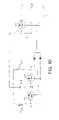
- FIG. 7illustrates a secondary circuit having capacitive dividers to divide the voltages applied to the control terminals of the controlled rectifiers.
- FIG. 8shows an alternative embodiment in which the output is regulated by controlling the voltage applied to the control terminals of the controlled rectifiers.
- FIG. 9illustrates an embodiment of the invention in which the primary windings are tightly coupled.
- FIG. 10illustrates the use of an ORing controlled rectifier to couple the power converter to an output bus.
- One embodiment of the invention described hereinpertains to an electrically isolated DDC converter that might be used to deliver power at a low DC voltage (e.g. 5 volts) from a DC source such as a battery or a rectified utility.
- a transformeris used to provide the electrical isolation and to provide a step-down (or step-up) in voltage level according to its turns-ratio.
- Switches in the form of power semiconductor transistors and diodesare used in conjunction with capacitors and inductors to create the conversion.
- a control circuitis typically included to provide the drive signals to the transistors' control terminals.
- the switching frequencyis high (e.g. 100 kHz and above) it is typical today to use power MOSFETs and Schottky diodes for the converter's switches since these majority carrier devices can undergo faster switch transitions than minority carrier devices such as power bipolar transistors and bipolar diodes.
- DDC convertersare designed to provide regulation of their output voltage in the face of input voltage and output current variations. For example, a converter might need to maintain a 5 volt output (plus or minus a few percent) as its input varies over the range of 36 to 75 volts and its output current ranges from 1 to 25 amps. This ability to provide regulation is usually the result of the power circuit's topology and the manner in which its switching devices are controlled. Sometimes the regulation function is supplied by (or augmented with) a linear regulator.
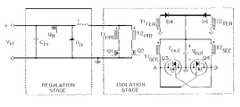
- FIG. 1shows a block diagram of a DDC converter that represents one embodiment of the invention. It shows a two stage converter structure where the power first flows through one stage and then through the next. One stage provides the regulation function and the other provides the electrical isolation and/or step-down (or step-up) function. In this embodiment the regulation stage is situated before the isolation stage, but this ordering is not necessary for the invention. Notice also that the block diagram shows a control function. As mentioned, the purpose of this control function is to determine when the transistors in the power circuit will be turned on and off (or to determine the drive of a linear regulator). To aid in this function the control circuit typically senses voltages and currents at the input, at the output, and/or within the power circuit.
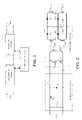
- FIG. 2shows one way to implement the two power stages represented in the block diagram of FIG. 1 .
- diodesrather than synchronous rectifiers, are used to simplify the initial description of the circuit's operation.
- the topology of the regulation stageis that of a “down converter”.
- This canonical switching cellhas a capacitor, C IN , a transistor, Q R , a diode, D R , and an inductor, L.
- Regulationis by control of the duty cycle of the transistor Q R in response to one or more parameters sensed in the circuit.
- the regulation stagecan be modified by providing higher order filters at its input and output, by replacing the diode with a synchronous rectifier, by adding resonant elements to create a “multi-resonant” converter and the like.
- the topology of the isolation stage shown in FIG. 2has two transformers that are not, in this case, coupled.
- Each of these transformers T 1 and T 2has three windings: a primary winding T 1 PRI , T 2 PRI ; a secondary winding T 1 SEC , T 2 SEC ; and a tertiary winding T 1 TER , T 2 TER .
- the transformer windingsare connected through MOSFETs Q 1 and Q 2 on the primary windings and through diodes D 1 , D 2 , D 3 , and D 4 on the secondary and tertiary windings.
- the stageis “current-fed”, in this case by the inductor L from the output of the regulation stage.
- the output filteris simply a capacitor C OUT whose voltage is relatively constant over the time frame of the switching cycle. Additional filtering stages could be added to this output filter in a known manner.
- the operation of the isolation stageproceeds in the following manner. First, for approximately one half of the switching cycle, transistor Q 1 is on and Q 2 is off. The current flowing through inductor L therefore flows through the primary winding of transformer T 1 , and a corresponding current (transformed by the turns ratio) flows through the secondary winding of T 1 and through diode D 1 to the output filter capacitor C OUT and the load. During this time the magnetizing current in T 1 is increasing due to the positive voltage placed across its windings. This positive voltage is determined by the output capacitor voltage, V OUT , plus the forward voltage drop of D 1 .
- transistor Q 2 and diode D 2are on and Q 1 and D 1 are off. While the current of inductor L flows through transformer T 2 in the same manner as described above for T 1 , the magnetizing current of transformer T 1 flows through its tertiary winding and diode D 3 to the output filter capacitor, C OUT .
- This arrangement of the tertiary windingprovides a means to reset the T 1 transformer core with a negative voltage and to recover most of the magnetizing inductance energy.
- the tertiary windingmay alternatively be connected to other suitable points in the power circuit, including those on the primary side of the transformer.
- the tertiary windingcould be eliminated and replaced with a conventional clamp circuit attached to either the primary or secondary winding and designed to impose a negative voltage across the transformer during its operative half cycle.
- Techniques to recover the energy delivered to this clamp circuitsuch as the one in which a transistor is placed in anti-parallel with a clamping diode so that energy can flow from the clamping circuitry back into the magnetizing inductance, could also be used.
- the old primary side transistor(say Q 1 ) is turned off.
- the voltage across this transistorrises as its parasitic capacitance is charged by the current that had been flowing through the channel.
- this voltagerises high enough to forward bias diode D 3 connected to the tertiary winding, the transistor voltage becomes clamped, although an over-ring and/or a commutation interval will occur due to parasitic leakage inductance.
- all of the current in inductor Lwill flow through switch Q 2 , switch Q 1 will be off, and the magnetizing current of T 1 will flow through diode D 3 .
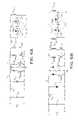
- FIG. 3Now replace output diodes D 1 and D 2 with MOSFET synchronous rectifiers Q 3 and Q 4 , as shown in FIG. 3 .
- the body diode of the MOSFET synchronous rectifieris explicitly shown since it plays a role in the circuit's operation.
- the schematical drawings of Q 3 and Q 4depict the need for a controlled rectifier (e.g. a transistor) and an uncontrolled rectifier (e.g. a diode) connected in parallel. These two devices may be monolithically integrated, as they are for power MOSFETs, or they may be separate components.
- the positions of these synchronous rectifiers in the circuitare slightly different than the positions of the diodes in FIG. 2 .
- the gates of the synchronous rectifier MOSFETsare cross-coupled to the opposite transformers.
- the voltage across one transformerdetermines the gate voltage, and therefore the conduction state (on or off) of the MOSFET connected to the other transformer, and vice versa.
- the current of inductor Lflows into the primary of T 1 and out its secondary.
- This secondary side currentwill flow through transistor Q 3 (note that even if Q 3 's channel is not turned on, the secondary side current will flow through the transistor's internal anti-parallel body diode).
- the voltage across transformer T 1 's secondary windingis therefore positive, and equal to the output voltage V OUT plus the voltage drop across Q 3 .
- the voltage across T 2 's secondary windingis negative during this time, with a magnitude approximately equal to the output voltage if the magnetizing inductance reset circuitry takes approximately the whole half cycle to finish its reset function. (The negative secondary winding voltage may be made greater than the positive voltage so that the core will finish its reset before the next half cycle begins. This could be accomplished, for example, by using less turns on the tertiary winding.)
- the voltage at node A during this state of operationis nearly zero with respect to the indicated secondary-side ground node (actually the voltage is slightly negative due to the drop across Q 3 ).
- the voltage at node Bis, following our example, approximately twice the output voltage (say 10 volts for a 5 volt output). Given the way these nodes are connected to the synchronous rectifier transistors, Q 3 is turned on and Q 4 is turned off. These respective conduction states are consistent with transformer T 1 delivering the power and transformer T 2 being reset.
- the sequence of operationis as follows. Start with Q 1 and Q 3 on, Q 2 and Q 4 off. (The clamp circuit's diode D 4 may still be on, or it may have stopped conducting at this point if the magnetizing inductance has finished resetting to zero.) First, Q 2 is turned on. If we ignore the effects of parasitic capacitances and inductances, the voltage across T 2 steps from a negative value to a positive value. The current flowing through inductor L splits between the two primary windings, causing current to flow out of both secondary windings. These secondary currents flow through Q 3 and Q 4 .
- FIG. 5shows the same topology as FIG. 3 , but with several important parasitic capacitances and inductances indicated schematically.
- Each indicated capacitor (C 3 and C 4 )represents the combined effect of one synchronous rectifier's input capacitance and the other rectifier's output capacitance, as well as other parasitic capacitances.
- Each indicated inductor (L P1 and L P2 )represents the combined effect of a transformer leakage inductance and the parasitic inductance associated with the loops formed by the primary side components and the secondary side components.
- the nearly lossless delivery and recovery of energyis achieved because the circuit topology permits the synchronous rectifier switch transitions to proceed as oscillations between inductors and capacitors. These transitions are short compared to the overall on-state and off-state portions of the switching cycle (e.g. less than 20% of the time is taken up by the transition). This characteristic of nearly lossless and relatively short transitions, which we will call soft switching, is distinct from that used in full resonant, quasi-resonant, or multi-resonant converters where the oscillations last for a large portion, if not all, of the on-state and/or off-state time.
- the way in which the soft-switching characteristic is achievedcan be understood in the following manner. Start with transistors Q 1 and Q 3 on, Q 2 and Q 4 off. The voltage at node A, and therefore the voltage across C 4 , is nearly zero and the voltage at node B (and across C 3 ) is approximately twice the output voltage.
- the current flowing through inductor L, I Lis flowing into the primary winding of T 1 .
- the current flowing out of the secondary winding of T 1is IL minus the current flowing in T 1 's magnetizing inductance, I M , both referenced to the secondary side.
- the magnetizing currentis increasing towards its maximum value, I MPK , which it reaches at the end of the half cycle.
- I LP2reaches (I L ⁇ I MPK ) first (and assuming the voltage across C 3 has fallen below the threshold voltage of Q 3 so that I LP1 is flowing through the body diode of Q 3 ), the oscillation stops because the body diode will not let I LP1 go negative.
- I LP2 and I LP1will hold constant at (I L ⁇ I MPK ) and zero, respectively. Whatever voltage remains across C 3 will then discharge linearly due to the current I LP2 until the body diode of Q 4 turns on. The body diode will then carry I LP2 until the overlap interval is over and Q 1 is turned off.
- the energy lost in this second scenariois a very small fraction (typically less than one ninth) of the total energy originally stored in (or delivered to) L P1 , L P2 , C 3 and C 4 . In other words, most of the parasitic energy is recovered.
- the size of the output filter required to achieve a given output voltage rippleis affected by the AC ripple in the current of inductor L. This ripple current is largely caused by the switching action of the preregulation stage. A larger inductance, or a higher order filter for the output of the regulation stage, as shown in FIG. 6 where inductor LB and capacitor C B have been added, will reduce this ripple current.
- the required size of the output filteris also affected by the AC ripple currents flowing in the magnetizing inductances of the transformers. Making these inductances as large as possible to reduce their ripple currents is therefore desirable. It is also beneficial to connect the tertiary reset windings back to a suitable point on the primary side as shown in FIG. 6A where they are connected to capacitor C B , rather than to connect them to the output filter, as shown in FIG. 3 . This alternative connection reduces by a factor of two the ripple current seen by the output filter due to the magnetizing inductance currents, compared to the connection shown in FIG. 3 , since these magnetizing currents no longer flow to the output capacitor during their respective reset half cycles.
- the power converter circuits described so farhave all had an isolation stage that is current fed. It is also possible to incorporate the invention with an isolation stage that is voltage fed. By “voltage fed” it is meant that the voltage across the primary side of the isolation stage is held relatively constant over the time frame of the switching cycle. Such a converter circuit is shown in FIG. 6B where two uncoupled transformers are used.
- each primary transistoris still turned on for approximately one half the cycle, but instead of providing a brief overlap period during which both primary transistors, Q 1 and Q 2 , are turned on together, here the primary transistors are both turned off for a brief overlap period.
- the current flowing into one primary winding and out its respective secondary windingcan be determined as follows. Say transistors Q 1 and Q 3 have just been turned on to begin a new half cycle. At the completion of their switch transition they will be carrying some initial current (to be discussed in more detail below). There is also a difference between the voltage across capacitor C B and the voltage across capacitor C OUT , both reflected to the secondary side. This voltage differential will be called ⁇ V. It appears across the series circuit composed of the leakage/parasitic inductances and resistances of the primary and secondary windings, T 1PRI and T 1SEC , the transistors Q 1 and Q 3 , and the capacitors C B and C OUT . The current flowing through this series L-R circuit responds to the voltage across it, ⁇ V, in accordance with the component values, all referenced to the secondary side.
- transistor Q 3will turn on and the current that had been flowing through the body diode of Q 3 will commutate to the channel of Q 3 .
- the new half cyclewill then proceed as discussed above, with Is being the initial value of current mentioned in that discussion.
- the transition between the two half cycleshas a period of time when the two body diodes are conducting. This condition is highly dissipative and should be kept short by keeping the overlap period that both primary side transistors, Q 1 and Q 2 , are off short.
- a resistorcould be placed in series with the gate of the primary side transistor Q 1 (or Q 2 ) in FIG. 5 so that its gate voltage would change more slowly.
- a resistorcould be placed in series with the gate of a synchronous rectifier Q 3 or (Q 4 ). In either case an RC circuit is created by the added resistor, R, and the capacitance, C, associated with the transistor. If this RC product is long compared to the normal length of the oscillatory transitions described above, the switch transitions will be slowed down.
- the synchronous rectifier MOSFETs Q 3 and Q 4 in the circuit of FIG. 3are driven with a gate-source voltage equal to approximately twice the output voltage. For a 5 volt output, the 10 volt drive that results is appropriate for common MOSFETs. If the output voltage is such that the gate drive voltage is too large for the ratings of the MOSFET, however, steps must be taken to reduce the drive voltage. For example, if the output voltage is 15 volts, a 30 volt gate drive will result, and it is typically desired that the gate be driven to only 10 volts. Also, some MOSFETs are designed to be driven with only 5 volts, or less, at their gates.
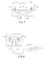
- FIG. 7shows one way to reduce the drive voltage while maintaining the energy recovery feature.
- the voltage waveform at node B(or at node A) is capacitively divided down by the series combination of capacitors C 5 and C 3 (or by C 6 and C 4 ).
- the values of these capacitorsare chosen to provide the division of the AC voltage provided at node B (or node A) as desired. For example, if node B has a 30 volt step change and a 10 volt step change is desired at the gate of Q 3 , then C 5 should have one half the capacitance of C 3 . Since C 3 may be comprised of the parasitic capacitance of Q 3 , it is likely to be nonlinear. In this case, an effective value of capacitance that relates the large scale change in charge to the large scale change in voltage should be used in the calculation to determine C 5 .
- FIG. 7shows one way to do this in which two resistors, R 1 and R 2 (or R 3 and R 4 ), provide the correct division of the DC component of the voltage at node B (or node A). These resistors should have values large enough to keep their dissipation reasonably small. On the other hand, the resistors should be small enough such that the time constant of the combined capacitor/resistor divider is short enough to respond to transients such as start-up.
- One variation of the invention described hereinwould be to create a power supply with multiple outputs by having more than one secondary winding on each transformer in the isolation stage. For example, by using two secondary windings with the same number of turns it would be possible to create a positive 12 volt output and a negative 12 volt output. If the two secondary windings have a different number of turns it would be possible to create two output voltages of different magnitudes (e.g., 5 volts and 3.3 volts). Another approach for creating multiple outputs would be to have multiple isolation stages, each with a turns-ratio appropriate for their respective output voltages.
- One advantageous approach to providing linear regulation with the power circuits described hereis to control how much the synchronous rectifier MOSFETs are turned on during their conduction state. This can be done by adding circuitry to limit the peak voltage to which their gates will be driven so that their on-state resistances can be made larger than their minimum values. It can also be done by controlling the portion of operative half cycle during which a MOSFET's gate voltage is allowed to be high so that the MOSFET's body diode conducts for the rest of the time. With both techniques, the amount to which the output voltage can be regulated is the difference between the voltage drop of the synchronous rectifiers when their channels are fully on (i.e., when they are at their minimum resistance) and when only their body diodes are carrying the current.
- One way to accomplish the first technique, that of controlling the peak gate voltage,is to use the basic capacitor divider circuit that was shown in FIG. 7 . All that is needed is to make the resistor divider ratio, (or, alternatively, the diode clamping voltage if such an approach is chosen) dependent on a control signal derived from the error in the output voltage compared to its desired value. The goal is to shift the DC component of the gate voltage in response to the error signal such that the peak voltage applied to the gate, and therefore the on-state resistance and voltage of the synchronous rectifier, helps to minimize this error.
- Various control circuitry schemesthat might be used to achieve this goal will be obvious to one skilled in the art. Note that this approach preserves the energy recovery feature of the gate drive. Note also that if the voltages at nodes A and B are such that no AC division is desired, then C 5 and C 6 should be made large compared to C 3 and C 4 .
- FIG. 8shows an alternative method to control the DC component of the gate voltage waveform.
- the output voltage(or a scaled version of it) is subtracted from a reference voltage and the error is multipled by the gain of an op-amp circuit.
- the output of the op-amp(node C) is then connected to the synchronous rectifier gates through resistors that are large enough to not significantly alter the AC waveforms at the gates. With this connection, the DC components of the gate voltages will equal the output voltage of the op-amp at node C. If the gain of the op-amp circuit is large enough, such as when an integrator is used, the error in the output voltage will be driven toward zero.
- Z F and Z Iare impedances that should be chosen, with well established techniques, to ensure stability of this feedback loop while providing the gain desired.
- the range of voltage required at the output of the op-ampdepends on the particular application, and it may include negative values. This range influences the supply voltage requirements for the op-amp. Also, if the op-amp's output voltage gets too high, the synchronous rectifiers may not turn off when they are supposed to. Some means of limiting this voltage, such as a clamp circuit, may therefore be desirable.
- One way to accomplish the second technique, that of controlling the portion of the half cycle in which the MOSFET is gated on,is to place a low power switch network between the gate of Q 3 (or Q 4 ), node B (or node A), and ground.
- This network(composed, say, of analog switches operated with digital control signals) might be used to keep the gate voltage grounded for some period of time after the node voltage increases, and to then connect the gate to node B (or A) for the remainder of the half cycle with a switch capable of bidirectional current flow. The length of the delay would be based on a signal derived from the error in the output voltage. With this approach, the energy recovery feature associated with discharging each synchronous rectifier's gate capacitance is preserved, but the charging transition will become lossy.
- the switch networkcould be controlled to start out the half cycle with the gate connected to node B (or A), and then after some delay to connect the gate to ground.
- Using a synchronous rectifier to provide regulation as well as rectification, as described above,is not limited to multiple-output situations. It can also be used in single-output situations either as the total regulation stage or as an additional regulation stage to augment the first one.
- DDC switching regulatorson the secondary side to achieve the additional regulation desired, or to create more than one output voltage from any of the outputs of the isolation stage.
- each controlled rectifierWith multiple outputs it is not necessary for the gate of each controlled rectifier to be connected to secondary winding of the other transformer which corresponds to the same output. For instance, if the two outputs are 5 volts and 3.3 volts, the gates of the 3.3 volts output controlled rectifiers could be connected to the 5 volt output secondary windings. Doing so would give these controlled rectifiers a 10 volt gate drive, resulting in a lower on-state resistance than if they had a 6.6 volt gate drive.
- the isolation stagefirst in the power flow, and to have the regulation stage follow.
- the circuitmight be configured as one isolation/step-down (or step-up) stage followed by several DDC switching or linear regulators.
- isolation stageNo matter where the isolation stage is situated, if it is to be current fed this requirement could be met with active circuitry as well as by a passive component such as an inductor. For instance, if the current fed isolation stage follows a regulation stage that is achieved with a linear regulator, then this linear regulator could be designed to have a large AC output impedance to achieve the input requirement of the current fed isolation stage.
- the voltage across C Bthe capacitor of the third-order output filter of the down converter, could be used.
- This voltagenearly represents the isolated output voltage (corrected for the turns-ratio). It differs only due to the resistive (and parasitic inductance commutation) drops between C B and the output. Since these drops are small and proportional to the current flowing through the isolation stage, the error in output voltage they create can either be tolerated or corrected.
- the current on the primary sidecould be sensed, multiplied by an appropriate gain, and the result used to modify the reference voltage to which the voltage across C B is compared. Since these resistive drops vary with temperature, it might also be desirable to include temperature compensation in the control circuitry. Note that this approach could also be used to correct for resistive drops along the leads connecting the supply's output to its load.
- the embodiments of the invention described abovehave used two uncoupled transformers for the isolation stage. It is also possible, as shown in FIG. 9 , to use a single transformer T in which, for example, there are two primary windings T PRI1 , T PRI2 and two secondary windings, T SEC1 , T SEC2 . While the two primary windings may be tightly coupled, either the two secondaries should be loosely coupled to each other or the connections to the output capacitors and synchronous rectifier transistors should provide adequate parasitic inductance. The resulting leakage and parasitic inductance on the secondary side can then be modeled as is shown in FIG. 9 .
- diodesWhen two or more power supplies are connected in parallel, diodes are sometimes placed in series with each supply's output to avoid a situation where one supply's failure, seen as a short at its output, takes down the entire output bus.
- These “ORing” diodestypically dissipate a significant amount of energy.
- One way to reduce this dissipationis to replace the diode with a MOSFET having a lower on-state voltage.
- This “ORing” synchronous rectifier MOSFETcan be placed in either output lead, with its body diode pointing in the direction of the output current flow.
- the voltage for driving the gate of this MOSFET, Q 5can be derived by connecting diodes to node A and/or node B (or to nodes of capacitor dividers connected to these nodes), as shown in FIG. 10 . These diodes rectify the switching waveforms at node A and/or node B to give a constant voltage suitable for turning on the ORing MOSFET at node D.
- a filter capacitor, CFmight be added to the circuit as shown in the figure, or the parasitic input capacitance of the ORing MOSFET might be used alone.
- a resistor R Fensures the gate voltage discharges when the drive is removed.
- the power supplyfails in a way that creates a short at its output, such as when a synchronous rectifier shorts, the voltages at nodes A and B will also be shorted after the transient is complete. With its gate drive no longer supplied, the ORing MOSFET will turn off, and the failed supply will be disconnected from the output bus.
- ORing MOSFET ⁇ s gate voltagerises high enough to turn it on before the newly rising output voltage approximately matches the existing bus voltage, then there will be at least a momentary large current flow as the two voltages equalize.
- additional circuitrycan be added to make sure an ORing MOSFET is not turned on until its supply's output voltage has approximately reached the bus voltage. This might be done by sensing the two voltages and taking appropriate action, or it might be done by providing a delay between when the ORing MOSFET's gate drive is made available and when it is actually applied to the gate. Such a delay should only affect the turn-on, however; the turn-off of the ORing MOSFET should have minimal delay so that the protective function of the transistor can be provided.
- the regulation stagecould be composed of an up-converter.
- the ideas that have been presented in terms of the N-channel implementation of the synchronous rectifier MOSFETcan be modified to apply to the P-channel implementation, as well.
- the components shown in the schematics of the figures(such as Q 3 in FIG. 3 ) could be implemented with several discrete parts connected in parallel.
- certain aspects of the inventioncould be applied to a power converter having only one primary transformer winding and/or one secondary transformer winding.
Landscapes
- Engineering & Computer Science (AREA)
- Power Engineering (AREA)
- Dc-Dc Converters (AREA)
- Amplifiers (AREA)
Abstract
Description
Claims (89)
Priority Applications (1)
| Application Number | Priority Date | Filing Date | Title |
|---|---|---|---|
| US11/901,263US7564702B2 (en) | 1997-01-24 | 2007-09-14 | High efficiency power converter |
Applications Claiming Priority (8)
| Application Number | Priority Date | Filing Date | Title |
|---|---|---|---|
| US3624597P | 1997-01-24 | 1997-01-24 | |
| US09/012,475US5999417A (en) | 1997-01-24 | 1998-01-23 | High efficiency power converter |
| US09/417,867US6222742B1 (en) | 1997-01-24 | 1999-10-13 | High efficiency power converter |
| US09/821,655US6594159B2 (en) | 1997-01-24 | 2001-03-29 | High efficiency power converter |
| US10/359,457US6731520B2 (en) | 1997-01-24 | 2003-02-05 | High efficiency power converter |
| US10/812,314US7072190B2 (en) | 1997-01-24 | 2004-03-29 | High efficiency power converter |
| US11/390,494US7272023B2 (en) | 1997-01-24 | 2006-03-27 | High efficiency power converter |
| US11/901,263US7564702B2 (en) | 1997-01-24 | 2007-09-14 | High efficiency power converter |
Related Parent Applications (1)
| Application Number | Title | Priority Date | Filing Date |
|---|---|---|---|
| US11/390,494ContinuationUS7272023B2 (en) | 1997-01-24 | 2006-03-27 | High efficiency power converter |
Publications (2)
| Publication Number | Publication Date |
|---|---|
| US20080151580A1 US20080151580A1 (en) | 2008-06-26 |
| US7564702B2true US7564702B2 (en) | 2009-07-21 |
Family
ID=21887510
Family Applications (7)
| Application Number | Title | Priority Date | Filing Date |
|---|---|---|---|
| US09/012,475Expired - LifetimeUS5999417A (en) | 1997-01-24 | 1998-01-23 | High efficiency power converter |
| US09/417,867Expired - LifetimeUS6222742B1 (en) | 1997-01-24 | 1999-10-13 | High efficiency power converter |
| US09/821,655Expired - LifetimeUS6594159B2 (en) | 1997-01-24 | 2001-03-29 | High efficiency power converter |
| US10/359,457Expired - Fee RelatedUS6731520B2 (en) | 1997-01-24 | 2003-02-05 | High efficiency power converter |
| US10/812,314Expired - LifetimeUS7072190B2 (en) | 1997-01-24 | 2004-03-29 | High efficiency power converter |
| US11/390,494Expired - Fee RelatedUS7272023B2 (en) | 1997-01-24 | 2006-03-27 | High efficiency power converter |
| US11/901,263Expired - Fee RelatedUS7564702B2 (en) | 1997-01-24 | 2007-09-14 | High efficiency power converter |
Family Applications Before (6)
| Application Number | Title | Priority Date | Filing Date |
|---|---|---|---|
| US09/012,475Expired - LifetimeUS5999417A (en) | 1997-01-24 | 1998-01-23 | High efficiency power converter |
| US09/417,867Expired - LifetimeUS6222742B1 (en) | 1997-01-24 | 1999-10-13 | High efficiency power converter |
| US09/821,655Expired - LifetimeUS6594159B2 (en) | 1997-01-24 | 2001-03-29 | High efficiency power converter |
| US10/359,457Expired - Fee RelatedUS6731520B2 (en) | 1997-01-24 | 2003-02-05 | High efficiency power converter |
| US10/812,314Expired - LifetimeUS7072190B2 (en) | 1997-01-24 | 2004-03-29 | High efficiency power converter |
| US11/390,494Expired - Fee RelatedUS7272023B2 (en) | 1997-01-24 | 2006-03-27 | High efficiency power converter |
Country Status (6)
| Country | Link |
|---|---|
| US (7) | US5999417A (en) |
| EP (1) | EP0954899A2 (en) |
| JP (1) | JP2002514378A (en) |
| AU (1) | AU722043B2 (en) |
| CA (1) | CA2278250A1 (en) |
| WO (1) | WO1998033267A2 (en) |
Cited By (30)
| Publication number | Priority date | Publication date | Assignee | Title |
|---|---|---|---|---|
| US20100102875A1 (en)* | 2008-10-29 | 2010-04-29 | Freescale Semiconductor, Inc | Substrate noise passive cancellation method for buck converter |
| US20100250993A1 (en)* | 2009-03-31 | 2010-09-30 | Quantance, Inc. | High speed power supply system |
| US20110216560A1 (en)* | 2010-03-04 | 2011-09-08 | Sheng Ye | Two stage isolated switch-mode ac/dc converter |
| US8023290B2 (en) | 1997-01-24 | 2011-09-20 | Synqor, Inc. | High efficiency power converter |
| US20110267844A1 (en)* | 2010-04-30 | 2011-11-03 | Yi He | Controller for a Resonant Switched-Mode Power Converter |
| WO2012116750A1 (en) | 2011-03-03 | 2012-09-07 | Telefonaktiebolaget L M Ericsson (Publ) | Controlling a switched mode power supply with maximised power efficiency |
| WO2013113354A1 (en) | 2012-01-30 | 2013-08-08 | Telefonaktiebolaget Lm Ericsson (Publ) | Controlling a switched mode power supply with maximised power efficiency |
| US20130200859A1 (en)* | 2010-07-30 | 2013-08-08 | Abb Technology Ag | Capacitor discharge in a cell based voltage source converter |
| WO2013156079A1 (en) | 2012-04-20 | 2013-10-24 | Telefonaktiebolaget Lm Ericsson (Publ) | Controlling a switched mode power supply with maximised power efficiency |
| WO2013182249A1 (en) | 2012-06-08 | 2013-12-12 | Telefonaktiebolaget L M Ericsson (Publ) | Controlling a switched mode power supply with maximised power efficiency |
| US8617154B2 (en) | 2010-06-25 | 2013-12-31 | Covidien Lp | Current-fed push-pull converter with passive voltage clamp |
| US20140022826A1 (en)* | 2011-01-28 | 2014-01-23 | Lian Zheng Electronics (Shenzhen) Co., Ltd. | Quasi resonant push-pull converter and control method thereof |
| US8665611B2 (en) | 2010-04-30 | 2014-03-04 | Infineon Technologies Ag | Controller for a resonant switched-mode power converter |
| US8890502B2 (en) | 2012-02-17 | 2014-11-18 | Quantance, Inc. | Low-noise, high bandwidth quasi-resonant mode switching power supply |
| US8934267B2 (en) | 2010-11-09 | 2015-01-13 | Tdk-Lambda Corporation | Loosely regulated feedback control for high efficiency isolated DC-DC converters |
| US8937468B2 (en) | 2012-08-13 | 2015-01-20 | Northrop Grumman Systems Corporation | Power supply systems and methods |
| US8952753B2 (en) | 2012-02-17 | 2015-02-10 | Quantance, Inc. | Dynamic power supply employing a linear driver and a switching regulator |
| US9118213B2 (en) | 2010-11-24 | 2015-08-25 | Kohler Co. | Portal for harvesting energy from distributed electrical power sources |
| US20160049882A1 (en)* | 2014-04-16 | 2016-02-18 | Huawei Technologies Co., Ltd. | Resonant converter and synchronous rectification converter circuit thereof |
| US9281749B2 (en) | 2012-08-13 | 2016-03-08 | Northrop Grumman Systems Corporation | Multiple power supply systems and methods |
| US9362832B2 (en) | 2014-02-25 | 2016-06-07 | Telefonaktiebolaget L M Ericsson (Publ) | Intermediate bus architecture power supply |
| US9391504B2 (en) | 2012-02-09 | 2016-07-12 | Telefonaktiebolaget L M Ericsson (Publ) | Control of transformer flux density in an isolated switched mode power supply |
| US9397578B2 (en) | 2012-02-17 | 2016-07-19 | Telefonaktiebolaget L M Ericsson (Publ) | Voltage feed-forward compensation and voltage feedback compensation for switched mode power supplies |
| US9520772B2 (en) | 2010-11-09 | 2016-12-13 | Tdk-Lambda Corporation | Multi-level voltage regulator system |
| US9698694B2 (en) | 2014-01-10 | 2017-07-04 | Astec International Limited | Control circuits and methods for regulating output voltages based on adjustable references voltages |
| US9866133B2 (en) | 2014-01-10 | 2018-01-09 | Astec International Limited | Control circuits and methods for regulating output voltages using multiple and/or adjustable reference voltages |
| US10199950B1 (en) | 2013-07-02 | 2019-02-05 | Vlt, Inc. | Power distribution architecture with series-connected bus converter |
| US10468965B2 (en) | 2016-07-07 | 2019-11-05 | Queen's University At Kingston | Multi-stage multilevel DC-DC step-down converter |
| US11223289B2 (en) | 2020-01-17 | 2022-01-11 | Astec International Limited | Regulated switched mode power supplies having adjustable output voltages |
| US11407322B2 (en) | 2019-09-05 | 2022-08-09 | Hong Kong Applied Science and Technology Research Institute Company, Limited | Smart power hub |
Families Citing this family (123)
| Publication number | Priority date | Publication date | Assignee | Title |
|---|---|---|---|---|
| US5999417A (en) | 1997-01-24 | 1999-12-07 | Fische, Llc | High efficiency power converter |
| US7272021B2 (en)* | 1997-01-24 | 2007-09-18 | Synqor, Inc. | Power converter with isolated and regulated stages |
| US7050309B2 (en)* | 2002-12-06 | 2006-05-23 | Synqor, Inc. | Power converter with output inductance |
| US6441590B1 (en)* | 1999-03-26 | 2002-08-27 | Sarnoff Corporation | Two stage architecture for a monitor power supply |
| US6594156B1 (en)* | 2000-04-24 | 2003-07-15 | Minimed Inc. | Device and method for circuit protection during radiation sterilization |
| US6894468B1 (en) | 1999-07-07 | 2005-05-17 | Synqor, Inc. | Control of DC/DC converters having synchronous rectifiers |
| US6246592B1 (en) | 1999-08-10 | 2001-06-12 | Texas Instruments Incorporated | Unique power supply architecture with cascaded converters for large input-to-output step-down ratio |
| US6169683B1 (en)* | 1999-10-07 | 2001-01-02 | Ericsson Inc. | Resonant gate drive for synchronous rectifiers |
| US6961253B1 (en) | 1999-10-08 | 2005-11-01 | Lambda Electronics | Drive circuits for synchronous rectifiers |
| US6442047B1 (en) | 1999-10-08 | 2002-08-27 | Lambda Electronics, Inc. | Power conversion apparatus and methods with reduced current and voltage switching |
| US6370039B1 (en) | 1999-11-19 | 2002-04-09 | Iwatt | Isolated power converter having primary feedback control |
| US6381150B2 (en) | 1999-11-19 | 2002-04-30 | Iwatt | Isolated dual converter having primary side internal feedback for output regulation |
| US6304460B1 (en)* | 2000-05-05 | 2001-10-16 | Slobodan Cuk | Switching DC-to-DC converter utilizing a soft switching technique |
| US6195270B1 (en) | 2000-06-19 | 2001-02-27 | Technical Witts, Inc. | Self clamping zero voltage switching DC transformers |
| US6341073B1 (en)* | 2000-11-16 | 2002-01-22 | Philips Electronics North America Corporation | Multiple valley controller for switching circuit |
| US6831847B2 (en)* | 2000-11-20 | 2004-12-14 | Artesyn Technologies, Inc. | Synchronous rectifier drive circuit and power supply including same |
| US6570268B1 (en) | 2000-11-20 | 2003-05-27 | Artesyn Technologies, Inc. | Synchronous rectifier drive circuit and power supply including same |
| US6400582B1 (en) | 2000-11-21 | 2002-06-04 | International Business Machines Corporation | Dual forward power converter utilizing coupling capacitors for improved efficiency |
| US6437999B1 (en)* | 2001-05-12 | 2002-08-20 | Technical Witts, Inc. | Power electronic circuits with ripple current cancellation |
| US6504735B2 (en) | 2001-03-12 | 2003-01-07 | 02 Micro International Ltd. | Regulated voltage reducing high-voltage isolated DC/DC converter system |
| EP1257048B1 (en)* | 2001-05-09 | 2017-10-04 | Philips Lighting Holding B.V. | Regulation device for a resonant converter |
| GB2377823B (en)* | 2001-06-15 | 2005-11-23 | Marconi Applied Technologies | Transformer/rectifier arrangement |
| US6445597B1 (en) | 2001-06-28 | 2002-09-03 | Tyco Electronics Logistics Ag | Local loop control system for a multiple output power converter |
| US6442052B1 (en) | 2001-08-30 | 2002-08-27 | International Business Machines Corporation | High efficiency power converter with fast transient response |
| AU2002363744A1 (en)* | 2001-11-13 | 2003-05-26 | Synqor, Inc. | Half-bridge isolation stage topologies |
| AU2002357442A1 (en)* | 2002-01-04 | 2003-07-30 | Fujitsu Siemens Computers Gmbh | Switched-mode power supply unit |
| US6937483B2 (en)* | 2002-01-16 | 2005-08-30 | Ballard Power Systems Corporation | Device and method of commutation control for an isolated boost converter |
| US6975098B2 (en)* | 2002-01-31 | 2005-12-13 | Vlt, Inc. | Factorized power architecture with point of load sine amplitude converters |
| US6930893B2 (en)* | 2002-01-31 | 2005-08-16 | Vlt, Inc. | Factorized power architecture with point of load sine amplitude converters |
| US6781853B2 (en)* | 2002-03-13 | 2004-08-24 | Virginia Tech Intellectual Properties, Inc. | Method and apparatus for reduction of energy loss due to body diode conduction in synchronous rectifiers |
| GB2393336B (en)* | 2002-09-20 | 2005-07-20 | Coutant Lambda Ltd | Multi-resonant power conversion apparatus and methods |
| US7477529B2 (en)* | 2002-11-01 | 2009-01-13 | Honeywell International Inc. | High-voltage power supply |
| NL1022226C2 (en)* | 2002-12-20 | 2004-07-19 | Leader Electronics Europ B V | Device and method for converting an alternating voltage. |
| JP2004215376A (en)* | 2002-12-27 | 2004-07-29 | Sony Corp | Switching power supply circuit |
| US7057906B2 (en)* | 2003-03-11 | 2006-06-06 | Denso Corporation | Insulating switching DC/DC converter |
| CN100392963C (en)* | 2003-04-17 | 2008-06-04 | 中兴通讯股份有限公司 | Low voltage largecurrent modle power source |
| KR100510143B1 (en)* | 2003-07-01 | 2005-08-25 | 삼성전자주식회사 | Method for compensating power factor, appratus therefor and power supplyer thereof |
| JP2005110486A (en)* | 2003-08-06 | 2005-04-21 | Sony Corp | Switching power circuit |
| EP1816734A3 (en) | 2003-08-21 | 2007-11-21 | Marvell World Trade Ltd. | Voltage regulator |
| US7760525B2 (en)* | 2003-08-21 | 2010-07-20 | Marvell World Trade Ltd. | Voltage regulator |
| US7872454B2 (en)* | 2003-08-21 | 2011-01-18 | Marvell World Trade Ltd. | Digital low dropout regulator |
| US7102251B2 (en) | 2003-08-22 | 2006-09-05 | Distributed Power, Inc. | Bi-directional multi-port inverter with high frequency link transformer |
| JP4439979B2 (en)* | 2003-09-17 | 2010-03-24 | 太陽誘電株式会社 | Power supply |
| US9153960B2 (en) | 2004-01-15 | 2015-10-06 | Comarco Wireless Technologies, Inc. | Power supply equipment utilizing interchangeable tips to provide power and a data signal to electronic devices |
| US7149096B2 (en)* | 2004-02-18 | 2006-12-12 | Astec International Limited | Power converter with interleaved topology |
| US7408795B2 (en)* | 2004-02-24 | 2008-08-05 | Vlt, Inc. | Energy storage and hold-up method and apparatus for high density power conversion |
| US7782639B2 (en)* | 2004-02-24 | 2010-08-24 | Vlt, Inc. | Adaptively configured and autoranging power converter arrays |
| US7170764B2 (en)* | 2004-02-24 | 2007-01-30 | Vlt, Inc. | Adaptively configured voltage transformation module array |
| US7212419B2 (en)* | 2004-02-24 | 2007-05-01 | Vlt, Inc. | Adaptively configured and autoranging voltage transformation module arrays |
| US7561446B1 (en) | 2005-09-15 | 2009-07-14 | Vlt, Inc. | Double-clamped ZVS buck-boost power converter |
| US7548441B2 (en) | 2004-02-24 | 2009-06-16 | Vlt, Inc. | Universal AC adapter |
| US8324872B2 (en) | 2004-03-26 | 2012-12-04 | Marvell World Trade, Ltd. | Voltage regulator with coupled inductors having high coefficient of coupling |
| US7190152B2 (en) | 2004-07-13 | 2007-03-13 | Marvell World Trade Ltd. | Closed-loop digital control system for a DC/DC converter |
| US7202646B2 (en)* | 2004-08-02 | 2007-04-10 | Vlt, Inc. | Control interface with droop compensation |
| JP4403926B2 (en)* | 2004-08-30 | 2010-01-27 | サンケン電気株式会社 | DC power supply |
| US20060043490A1 (en)* | 2004-09-02 | 2006-03-02 | Texas Instruments Incorporated | Electrostatic discharge (ESD) detection and protection |
| US7531918B2 (en)* | 2005-03-30 | 2009-05-12 | Hewlett-Packard Development Company, L.P. | Hot insertion and extraction of power supply module |
| US7272024B2 (en)* | 2005-06-08 | 2007-09-18 | Tamura Corporation | Synchronized rectification circuit and switching power supply device |
| JP2006345641A (en)* | 2005-06-09 | 2006-12-21 | Toyota Industries Corp | Dc/ac converter circuit and method for converting dc into ac |
| DE102006002698A1 (en)* | 2006-01-19 | 2007-08-02 | Conergy Ag | Inverter circuit for mains supply and for mains-independent operation |
| US7554796B2 (en)* | 2006-01-20 | 2009-06-30 | Adc Telecommunications, Inc. | Modular power distribution system and methods |
| US20070211500A1 (en)* | 2006-03-02 | 2007-09-13 | Hipro Electronic Co., Ltd | DC-DC converter with direct driven synchronous rectifier |
| US20090310392A1 (en)* | 2006-03-10 | 2009-12-17 | George Young | power converter |
| US7787261B2 (en)* | 2006-11-01 | 2010-08-31 | Synqor, Inc. | Intermediate bus architecture with a quasi-regulated bus converter |
| US8054652B2 (en)* | 2007-07-16 | 2011-11-08 | Texas Instruments Incorporated | Systems and methods for off-time control in a voltage converter |
| US7796406B2 (en) | 2007-07-31 | 2010-09-14 | Lumenis Ltd. | Apparatus and method for high efficiency isolated power converter |
| EP2051360B1 (en)* | 2007-10-17 | 2016-09-21 | Power Systems Technologies GmbH | Control circuit for a primary controlled switching power supply with increased accuracy of voltage regulation and primary controlled switched mode power supply |
| US8039989B2 (en)* | 2007-11-27 | 2011-10-18 | International Business Machines Corporation | Apparatus, system, and method for a low cost multiple output redundant power supply |
| EP2283408A2 (en)* | 2008-05-13 | 2011-02-16 | Igo, Inc. | Circuit and method for ultra-low idle power |
| US8693213B2 (en) | 2008-05-21 | 2014-04-08 | Flextronics Ap, Llc | Resonant power factor correction converter |
| US7770039B2 (en)* | 2008-05-29 | 2010-08-03 | iGo, Inc | Primary side control circuit and method for ultra-low idle power operation |
| US7779278B2 (en)* | 2008-05-29 | 2010-08-17 | Igo, Inc. | Primary side control circuit and method for ultra-low idle power operation |
| JP2010004633A (en)* | 2008-06-19 | 2010-01-07 | Sanken Electric Co Ltd | Dc power supply apparatus |
| US7800252B2 (en)* | 2008-06-27 | 2010-09-21 | Igo, Inc. | Load condition controlled wall plate outlet system |
| US7795759B2 (en)* | 2008-06-27 | 2010-09-14 | iGo, Inc | Load condition controlled power strip |
| US7795760B2 (en)* | 2008-07-25 | 2010-09-14 | Igo, Inc. | Load condition controlled power module |
| US8199529B2 (en)* | 2008-09-04 | 2012-06-12 | Astec International Limited | Inductorless isolated power converters with zero voltage and zero current switching |
| CN102047549B (en)* | 2009-01-07 | 2018-05-04 | 德克萨斯仪器股份有限公司 | Scan frequency LLC resonance power adjusters |
| JP5157987B2 (en)* | 2009-03-25 | 2013-03-06 | 株式会社豊田自動織機 | Isolated DC-DC converter |
| US9755630B2 (en)* | 2009-04-30 | 2017-09-05 | The United States of America as represented by the Secretary of the Government | Solid-state circuit breakers and related circuits |
| US8787044B2 (en)* | 2009-05-07 | 2014-07-22 | Flextronics Ap, Llc | Energy recovery snubber circuit for power converters |
| US8891803B2 (en)* | 2009-06-23 | 2014-11-18 | Flextronics Ap, Llc | Notebook power supply with integrated subwoofer |
| US20110149613A1 (en)* | 2009-12-23 | 2011-06-23 | Comarco Wireless Technologies, Inc. | Flyback converter utilizing boost inductor between ac source and bridge rectifier |
| DE102010000934A1 (en)* | 2010-01-15 | 2011-07-21 | Osram Gesellschaft mit beschränkter Haftung, 81543 | rectifier |
| CN101741258B (en)* | 2010-01-19 | 2012-05-09 | 魏其萃 | Isolative current regulation type direct current-direct current converter |
| US8000118B1 (en) | 2010-03-15 | 2011-08-16 | Varentec Llc | Method and system for delivering a controlled voltage |
| US8964413B2 (en)* | 2010-04-22 | 2015-02-24 | Flextronics Ap, Llc | Two stage resonant converter enabling soft-switching in an isolated stage |
| US8472221B1 (en)* | 2010-05-07 | 2013-06-25 | Alfred E. Mann Foundation For Scientific Research | High voltage rectifier using low voltage CMOS process transistors |
| JP5504129B2 (en)* | 2010-10-18 | 2014-05-28 | 東芝テック株式会社 | Power converter |
| TWI427887B (en) | 2010-11-03 | 2014-02-21 | Delta Electronics Inc | High voltage power supply module and power supply system using the same |
| US8520410B2 (en) | 2010-11-09 | 2013-08-27 | Flextronics Ap, Llc | Virtual parametric high side MOSFET driver |
| US9083247B2 (en)* | 2011-04-25 | 2015-07-14 | Fairchild Semiconductor Corporation | Synchronous rectifier control techniques for a resonant converter |
| KR101228797B1 (en)* | 2011-05-30 | 2013-01-31 | 한국과학기술원 | Power supply |
| US8737094B2 (en)* | 2011-11-17 | 2014-05-27 | Ixys Corporation | Transformer drive for low conduction loss rectifier in flyback converter |
| US8970067B2 (en) | 2011-11-30 | 2015-03-03 | Futurewei Technologies, Inc. | Hybrid DC/DC converters and methods |
| US9276460B2 (en) | 2012-05-25 | 2016-03-01 | Flextronics Ap, Llc | Power converter with noise immunity |
| US9203292B2 (en) | 2012-06-11 | 2015-12-01 | Power Systems Technologies Ltd. | Electromagnetic interference emission suppressor |
| US9203293B2 (en) | 2012-06-11 | 2015-12-01 | Power Systems Technologies Ltd. | Method of suppressing electromagnetic interference emission |
| US9019726B2 (en) | 2012-07-13 | 2015-04-28 | Flextronics Ap, Llc | Power converters with quasi-zero power consumption |
| US9019727B2 (en)* | 2012-07-18 | 2015-04-28 | Linear Technology Corporation | Temperature compensation of output diode in an isolated flyback converter |
| US9019724B2 (en) | 2012-07-27 | 2015-04-28 | Flextronics Ap, Llc | High power converter architecture |
| US9287792B2 (en) | 2012-08-13 | 2016-03-15 | Flextronics Ap, Llc | Control method to reduce switching loss on MOSFET |
| US9312775B2 (en) | 2012-08-15 | 2016-04-12 | Flextronics Ap, Llc | Reconstruction pulse shape integrity in feedback control environment |
| US9318965B2 (en) | 2012-10-10 | 2016-04-19 | Flextronics Ap, Llc | Method to control a minimum pulsewidth in a switch mode power supply |
| US9605860B2 (en) | 2012-11-02 | 2017-03-28 | Flextronics Ap, Llc | Energy saving-exhaust control and auto shut off system |
| US9660540B2 (en) | 2012-11-05 | 2017-05-23 | Flextronics Ap, Llc | Digital error signal comparator |
| US9323267B2 (en) | 2013-03-14 | 2016-04-26 | Flextronics Ap, Llc | Method and implementation for eliminating random pulse during power up of digital signal controller |
| US9494658B2 (en) | 2013-03-14 | 2016-11-15 | Flextronics Ap, Llc | Approach for generation of power failure warning signal to maximize useable hold-up time with AC/DC rectifiers |
| US9184668B2 (en) | 2013-03-15 | 2015-11-10 | Flextronics Ap, Llc | Power management integrated circuit partitioning with dedicated primary side control winding |
| US9490651B2 (en) | 2013-03-15 | 2016-11-08 | Flextronics Ap, Llc | Sweep frequency mode for magnetic resonant power transmission |
| US8654553B1 (en) | 2013-03-15 | 2014-02-18 | Flextronics Ap, Llc | Adaptive digital control of power factor correction front end |
| US9712063B2 (en) | 2013-04-15 | 2017-07-18 | Futurewei Technologies, Inc. | Apparatus and method for loosely regulated power converters |
| US9407154B2 (en)* | 2013-06-14 | 2016-08-02 | Advanced Charging Technologies, LLC | Electrical circuit for delivering power to consumer electronic devices |
| DE102014201581A1 (en)* | 2014-01-29 | 2015-07-30 | Robert Bosch Gmbh | On-board network isolation circuit for DC-DC converter and method for separating a vehicle electrical system from a DC-DC converter |
| FR3023083B1 (en)* | 2014-06-30 | 2018-03-16 | Valeo Siemens Eautomotive France Sas | VOLTAGE CONVERTER COMPRISING AN ISOLATED DC / DC CONVERTER CIRCUIT |
| US9621053B1 (en) | 2014-08-05 | 2017-04-11 | Flextronics Ap, Llc | Peak power control technique for primary side controller operation in continuous conduction mode |
| HK1252919A1 (en) | 2015-06-23 | 2019-06-06 | Tm4股份有限公司 | Physical topology for a power converter |
| KR101832296B1 (en) | 2016-04-26 | 2018-02-26 | 엠투파워 주식회사 | Foward-flyback bus converter |
| FR3056038B1 (en)* | 2016-09-12 | 2018-10-12 | Valeo Systemes De Controle Moteur | VOLTAGE CONVERTER WITH TWO CIRCUITS VOLTAGE CONVERTER CHAINS |
| US10381822B2 (en) | 2016-12-12 | 2019-08-13 | Google Llc | Oring control using low voltage device for high voltage DC rack |
| WO2018125104A1 (en)* | 2016-12-28 | 2018-07-05 | Halliburton Energy Services, Inc. | Current-to-voltage power converter |
| CN108988400B (en)* | 2018-07-03 | 2021-04-27 | 中国科学院广州能源研究所 | Power distribution method for multi-machine parallel power electronic transformer and electronic equipment |
| KR102801403B1 (en)* | 2019-11-18 | 2025-04-30 | 삼성전자주식회사 | Electronic device for performing power management and method for operating thereof |
Citations (729)
| Publication number | Priority date | Publication date | Assignee | Title |
|---|---|---|---|---|
| US1181803A (en) | 1914-07-31 | 1916-05-02 | Gen Electric | Attachment-plug. |
| US2042274A (en) | 1933-12-30 | 1936-05-26 | Standard Oil Dev Co | Method and apparatus for protecting oil storage tanks |
| US2497534A (en) | 1947-09-13 | 1950-02-14 | Gen Electric | Circuits for high-frequency operation of fluorescent lamps |
| US2852730A (en) | 1955-09-23 | 1958-09-16 | Motorola Inc | Power supply |
| US2902862A (en) | 1955-05-16 | 1959-09-08 | Harry G Twiford | Static wheel balancer |
| US2953738A (en) | 1954-06-02 | 1960-09-20 | Westinghouse Electric Corp | Rectifier device |
| US3008068A (en) | 1958-07-26 | 1961-11-07 | Philips Corp | Transistor voltage converter |
| US3029398A (en) | 1959-08-05 | 1962-04-10 | Thompson Ramo Wooldridge Inc | Converter |
| US3083328A (en) | 1959-12-10 | 1963-03-26 | Bell Telephone Labor Inc | Control circuit |
| US3141140A (en) | 1959-05-20 | 1964-07-14 | Acoustica Associates Inc | A. c. operated transistor oscillator or amplifier circuits |
| US3146406A (en) | 1959-07-04 | 1964-08-25 | Philips Corp | Transistor voltage converter |
| US3161837A (en) | 1961-07-27 | 1964-12-15 | Daven Company | Self-oscillatory direct-current to alternating-current inverters with magnetic amplifer controls |
| US3174042A (en) | 1962-03-01 | 1965-03-16 | White Ralph Effner | Distortion-free high voltage power supply |
| US3229111A (en) | 1961-10-27 | 1966-01-11 | Electro Seal Corp | A.c. power system having alternate sources of supply |
| US3241035A (en) | 1962-01-26 | 1966-03-15 | Warren Mfg Company Inc | A.c.-d.c. regulated power supply |
| US3295042A (en) | 1963-10-14 | 1966-12-27 | Robertshaw Controls Co | Capacitance to d. c. voltage converter |
| US3307073A (en) | 1964-04-02 | 1967-02-28 | Motorola Inc | Ignition system with series connected transistor and common core inductors to speed switching |
| US3313996A (en) | 1964-05-04 | 1967-04-11 | Honeywell Inc | Rectifier control apparatus |
| US3343073A (en) | 1964-07-13 | 1967-09-19 | Lorain Prod Corp | Regulated direct current power supply employing auxiliary cell |
| US3400325A (en) | 1966-01-28 | 1968-09-03 | Rca Corp | Voltage regulator including transient reducing means |
| US3435375A (en) | 1965-09-20 | 1969-03-25 | Motorola Inc | Controller having fet bridge circuit |
| US3443194A (en) | 1967-09-14 | 1969-05-06 | Ibm | Dc-to-dc converter with continuous feed to the load |
| US3448370A (en) | 1967-08-11 | 1969-06-03 | Bell Telephone Labor Inc | High frequency power inverter |
| US3454853A (en) | 1967-04-06 | 1969-07-08 | Honeywell Inc | Tracer servo control apparatus for a machine tool with slow down means for the feed axis |
| US3458798A (en) | 1966-09-15 | 1969-07-29 | Ibm | Solid state rectifying circuit arrangements |
| US3459957A (en) | 1967-07-19 | 1969-08-05 | Ite Imperial Corp | Voltage regulator circuit |
| US3471747A (en) | 1967-02-02 | 1969-10-07 | Gen Motors Corp | Starting circuit and solid state running circuit for high pressure arc lamp |
| US3495157A (en) | 1967-06-22 | 1970-02-10 | Forbro Design Corp | Preventing turn-off overshoot in regulated power supplies employing feedback regulation |
| US3506908A (en) | 1968-05-20 | 1970-04-14 | Trw Inc | Elimination of short circuit current of power transistors in push-pull inverter circuits |
| US3514692A (en) | 1967-06-22 | 1970-05-26 | Honeywell Inc | High efficiency voltage regulating circuit |
| US3517301A (en) | 1967-10-23 | 1970-06-23 | Bunker Ramo | Regulated power supply |
| US3553428A (en) | 1968-08-30 | 1971-01-05 | Du Pont | Apparatus and method for controlling the power supplied to a load |
| US3564393A (en) | 1969-03-12 | 1971-02-16 | North American Rockwell | Circuit using capacitor and switch on primary winding of transformer for regulating voltage on secondary winding of transformer |
| US3569818A (en) | 1969-07-22 | 1971-03-09 | Hughes Aircraft Co | Multiple output dc voltage regulator |
| US3573544A (en) | 1969-05-21 | 1971-04-06 | Energy Electronics | A gas discharge lamp circuit employing a transistorized oscillator |
| US3573494A (en) | 1968-01-12 | 1971-04-06 | Automatic Timing & Controls | Differential transformer demodulating circuit |
| US3573483A (en) | 1969-05-02 | 1971-04-06 | Essex International Inc | Power supply control apparatus |
| US3573597A (en) | 1969-12-29 | 1971-04-06 | Gen Electric | High current switching regulator with overlapped output current pulses |
| US3573508A (en) | 1968-09-27 | 1971-04-06 | Bell Telephone Labor Inc | Thyristor switch circuit |
| US3579026A (en) | 1969-01-02 | 1971-05-18 | Sylvania Electric Prod | Lamp ballast |
| US3581186A (en) | 1969-03-19 | 1971-05-25 | Motorola Inc | Reduced forward voltage drop rectifying circuit |
| US3582754A (en) | 1968-02-10 | 1971-06-01 | Wandel & Goltermann | Direct-current converter with overload protection |
| US3582758A (en) | 1969-09-30 | 1971-06-01 | Ibm | Rectifier using low saturation voltage transistors |
| US3584289A (en) | 1969-04-17 | 1971-06-08 | Bell Telephone Labor Inc | Regulated inverter using synchronized leading edge pulse width modulation |
| US3588595A (en) | 1969-11-26 | 1971-06-28 | Kidde & Co Walter | Fluorescent lamp ballast and thermal protective means therefor |
| US3599073A (en) | 1968-12-18 | 1971-08-10 | Texas Instruments Inc | Voltage-regulated power supply with standby power capability |
| US3604920A (en) | 1968-09-30 | 1971-09-14 | Donald M Niles | Portable fluorescent lantern |
| US3619713A (en) | 1969-04-01 | 1971-11-09 | Sola Basic Ind Inc | High-frequency lamp circuit for copying apparatus |
| US3629725A (en) | 1969-12-24 | 1971-12-21 | Bell Telephone Labor Inc | Driven inverter with low-impedance path to drain stored charge from switching transistors during the application of reverse bias |
| US3629648A (en) | 1969-07-31 | 1971-12-21 | Brent W Brown | Transistorized fluorescent tube operating circuit |
| US3638099A (en) | 1971-03-29 | 1972-01-25 | Collins Radio Co | Self-excited inverter employing commutation time transformers |
| US3643152A (en) | 1969-03-12 | 1972-02-15 | Hitachi Ltd | Collector follower-type transistorized voltage regulator with thermistor starting circuit |
| US3646395A (en) | 1970-05-15 | 1972-02-29 | American Optical Corp | High repetition rate laser optical pumping system |
| US3657631A (en) | 1969-12-19 | 1972-04-18 | Int Standard Electric Corp | Converter circuits |
| US3660672A (en) | 1971-02-25 | 1972-05-02 | Pioneer Magnetics Inc | Power supply dual output |
| US3663941A (en) | 1970-12-16 | 1972-05-16 | Nasa | Dc to ac to dc converter having transistor synchronous rectifiers |
| US3665203A (en) | 1971-03-15 | 1972-05-23 | Jerry D Hogg | Parallel direct current generators arrangement |
| US3668508A (en) | 1970-09-15 | 1972-06-06 | Acme Electric Corp | Regulator circuit |
| US3684891A (en) | 1970-09-28 | 1972-08-15 | Dual Lite Co | Fail-safe solid-state emergency lighting power supply and transfer circuit |
| US3696286A (en) | 1970-08-06 | 1972-10-03 | North American Rockwell | System for detecting and utilizing the maximum available power from solar cells |
| US3704381A (en) | 1971-09-02 | 1972-11-28 | Forbro Design Corp | High stability current regulator controlling high current source with lesser stability |
| US3710231A (en) | 1971-03-15 | 1973-01-09 | Westinghouse Electric Corp | D.c. static switch including means to suppress transient spikes between a drive source and the switch element |
| US3714545A (en) | 1971-04-30 | 1973-01-30 | Comteurs Schlumberger | Current transformer connection control |
| US3733538A (en) | 1972-03-28 | 1973-05-15 | Westinghouse Electric Corp | Apparatus for limiting instantaneous inverter current |
| US3735235A (en) | 1971-10-19 | 1973-05-22 | Bell Telephone Labor Inc | Dc to dc converter with voltage regulation feedback loop achieving isolation between input and output by time domain techniques |
| US3737755A (en) | 1972-03-22 | 1973-06-05 | Bell Telephone Labor Inc | Regulated dc to dc converter with regulated current source driving a nonregulated inverter |
| US3742242A (en) | 1971-06-09 | 1973-06-26 | Sony Corp | High and low voltage regulating circuit |
| US3743861A (en) | 1971-11-26 | 1973-07-03 | Honeywell Inc | Thyristor hard-firing circuit |
| US3751676A (en) | 1970-06-26 | 1973-08-07 | Matsushita Electric Industrial Co Ltd | Current control circuit for a plurality of loads |
| US3753071A (en) | 1972-06-15 | 1973-08-14 | Westinghouse Electric Corp | Low cost transistorized inverter |
| US3753076A (en) | 1972-04-27 | 1973-08-14 | Lighting Systems Inc | Inverter circuit and switching means |
| US3754177A (en) | 1972-09-05 | 1973-08-21 | Lectron Corp | Solid state controller |
| US3757195A (en) | 1972-08-11 | 1973-09-04 | Honeywell Inc | Isolated two wire signal transmitter |
| US3769545A (en) | 1972-05-25 | 1973-10-30 | Kodan Inc | Circuit arrangement for operating electric arc discharge devices |
| US3771040A (en) | 1972-04-18 | 1973-11-06 | Nasa | Regulated dc-to-dc converter for voltage step-up or step-down with input-output isolation |
| US3781638A (en) | 1972-06-28 | 1973-12-25 | Gen Electric | Power supply including inverter having multiple-winding transformer and control transistor for controlling main switching transistors and providing overcurrent protection |
| US3781505A (en) | 1972-06-28 | 1973-12-25 | Gen Electric | Constant duty cycle control of induction cooking inverter |
| US3787730A (en) | 1971-12-29 | 1974-01-22 | United Aircraft Corp | Bilateral high voltage dc system |
| US3805094A (en) | 1972-01-28 | 1974-04-16 | Honeywell Inf Systems | Driving circuit for a switching transistor |
| US3816810A (en) | 1973-01-02 | 1974-06-11 | Honeywell Inf Systems | High current, regulated power supply with fault protection |
| US3818312A (en) | 1971-09-17 | 1974-06-18 | Philips Corp | Dc-ac converter |
| US3818237A (en) | 1972-08-14 | 1974-06-18 | Hughes Aircraft Co | Means for providing redundancy of key system components |
| US3820008A (en) | 1971-12-29 | 1974-06-25 | Honeywell Inf Systems | Driving circuit for switching transistor |
| US3824450A (en) | 1973-05-14 | 1974-07-16 | Rca Corp | Power supply keep alive system |
| US3845404A (en) | 1972-06-16 | 1974-10-29 | T Trilling | Differential amplifier having active feedback circuitry |
| US3848175A (en) | 1973-10-24 | 1974-11-12 | Gen Electric | Starting inhibit scheme for an hvdc converter |
| US3851278A (en) | 1972-06-12 | 1974-11-26 | Bell & Howell Japan | Inverter circuit |
| US3851240A (en) | 1973-11-15 | 1974-11-26 | Gen Electric | Rectifier circuits using at least one multi-winding transformer in combination with transistors connected in an inverter mode and arranged in a bridge configuration |
| US3859638A (en) | 1973-05-31 | 1975-01-07 | Intersil Inc | Non-volatile memory unit with automatic standby power supply |
| US3873846A (en) | 1972-09-07 | 1975-03-25 | Sony Corp | Power supply system |
| US3879652A (en) | 1973-08-13 | 1975-04-22 | Westinghouse Electric Corp | AC solid state power controller with minimized internal power supply requirements |
| US3879647A (en) | 1974-06-07 | 1975-04-22 | Bell Telephone Labor Inc | DC to DC converter with regulation having accelerated soft start into active control region of regulation and fast response overcurrent limiting features |
| US3904950A (en) | 1975-01-27 | 1975-09-09 | Bell Telephone Labor Inc | Rectifier circuit |
| US3909695A (en) | 1973-10-17 | 1975-09-30 | Hewlett Packard Co | Regulation and stabilization in a switching power supply |
| US3909700A (en) | 1974-01-18 | 1975-09-30 | Gen Electric | Monolithic semiconductor rectifier circuit structure |
| US3912940A (en) | 1974-09-18 | 1975-10-14 | Honeywell Inc | Dc power supply |
| US3913002A (en) | 1974-01-02 | 1975-10-14 | Gen Electric | Power circuits for obtaining a high power factor electronically |
| US3913036A (en) | 1974-08-16 | 1975-10-14 | Victor Comptometer Corp | High-power, high frequency saturable core multivibrator power supply |
| US3916289A (en) | 1975-01-16 | 1975-10-28 | Us Air Force | DC to DC converter |
| US3919656A (en) | 1973-04-23 | 1975-11-11 | Nathan O Sokal | High-efficiency tuned switching power amplifier |
| US3927363A (en) | 1975-02-10 | 1975-12-16 | Rockwell International Corp | Current limited self-saturating dc/dc converter |
| US3930196A (en) | 1973-11-02 | 1975-12-30 | Gen Electric | Bridge rectifier circuits using transistors as rectifying elements |
| US3932764A (en) | 1974-05-15 | 1976-01-13 | Esb Incorporated | Transfer switch and transient eliminator system and method |
| US3938024A (en) | 1975-01-06 | 1976-02-10 | Bell Telephone Laboratories, Incorporated | Converter regulation by controlled conduction overlap |
| US3940682A (en) | 1973-10-15 | 1976-02-24 | General Electric Company | Rectifier circuits using transistors as rectifying elements |
| US3949238A (en) | 1975-01-13 | 1976-04-06 | Northern Electric Company, Limited | Distributed power switch for modular systems |
| US3959716A (en) | 1975-08-14 | 1976-05-25 | The Bendix Corporation | Wide input range switching voltage regulator |
| US3974397A (en) | 1975-04-01 | 1976-08-10 | S & C Electric Company | Multi-phase rectifier system |
| US3976932A (en) | 1975-04-15 | 1976-08-24 | General Electric Company | Bridge transistor inverter circuit |
| US3986052A (en) | 1975-05-29 | 1976-10-12 | North Electric Company | Power switching control circuit with enhanced turn-off drive |
| US3986097A (en) | 1975-06-30 | 1976-10-12 | Bell Telephone Laboratories, Incorporated | Bilateral direct current converters |
| US3989995A (en) | 1975-05-05 | 1976-11-02 | Bell Telephone Laboratories, Incorporated | Frequency stabilized single-ended regulated converter circuit |
| US3991319A (en) | 1975-12-05 | 1976-11-09 | Instrumentation & Control Systems Inc. | Standby power supply system |
| US4005335A (en) | 1975-07-15 | 1977-01-25 | Iota Engineering Inc. | High frequency power source for fluorescent lamps and the like |
| US4007413A (en) | 1975-12-08 | 1977-02-08 | Bell Telephone Laboratories, Incorporated | Converter utilizing leakage inductance to control energy flow and improve signal waveforms |
| US4010381A (en) | 1975-04-24 | 1977-03-01 | Bell Telephone Laboratories, Incorporated | No-break ac power supply |
| US4011518A (en) | 1975-10-28 | 1977-03-08 | The United States Of America As Represented By The Secretary Of The Navy | Microwave GaAs FET amplifier circuit |
| US4017784A (en) | 1976-05-17 | 1977-04-12 | Litton Systems, Inc. | DC to DC converter |
| US4017783A (en) | 1975-05-22 | 1977-04-12 | Telefonaktiebolaget L M Ericsson | Power transistor drive apparatus in a DC-converter |
| US4017746A (en) | 1975-07-18 | 1977-04-12 | Nartron Corporation | Timing circuit means |
| US4027228A (en) | 1975-04-15 | 1977-05-31 | General Electric Company | Photocoupled isolated switching amplifier circuit |
| US4037271A (en) | 1976-12-03 | 1977-07-19 | Boschert Associates | Switching regulator power supply |
| US4044268A (en) | 1976-01-05 | 1977-08-23 | The Gates Rubber Company | Multiple power source automatic switching circuitry |
| US4060757A (en) | 1976-09-17 | 1977-11-29 | General Electric Co. | Inverters having a transformer-coupled commutating circuit |
| US4066945A (en) | 1976-03-31 | 1978-01-03 | The Bendix Corporation | Linear driving circuit for a d.c. motor with current feedback |
| US4074182A (en) | 1976-12-01 | 1978-02-14 | General Electric Company | Power supply system with parallel regulators and keep-alive circuitry |
| US4078247A (en) | 1975-02-05 | 1978-03-07 | Rca Corporation | Inverter circuit control circuit for precluding simultaneous conduction of thyristors |
| US4104539A (en) | 1976-04-05 | 1978-08-01 | Hase A M | Parallel redundant and load sharing regulated AC system |
| US4106084A (en) | 1975-01-10 | 1978-08-08 | Societe Nationale Des Petroles D'aquitaine | Means for controlling the electric current density of a high tension direct current source |
| US4109192A (en) | 1976-06-25 | 1978-08-22 | Hughes Aircraft Company | Low power reactive drive circuit for capacitive loads |
| US4114048A (en) | 1976-03-10 | 1978-09-12 | Westinghouse Electric Corp. | Load balancing system for ups rectifiers |
| US4115704A (en) | 1977-04-27 | 1978-09-19 | The United States Of America As Represented By The Secretary Of The Navy | Parametric energy coupled uninterruptible power supply |
| US4122359A (en) | 1977-04-27 | 1978-10-24 | Honeywell Inc. | Memory protection arrangement |
| US4126793A (en) | 1975-12-03 | 1978-11-21 | Zellweger Uster Limited | Circuit arrangement for a remote control receiver |
| US4128868A (en) | 1977-03-30 | 1978-12-05 | Rca Corporation | D-C converter using pulsed resonant circuit |
| US4131860A (en) | 1976-12-31 | 1978-12-26 | Thomson-Csf | Power amplifier arrangement automatically matched to service conditions |
| US4140959A (en) | 1976-07-19 | 1979-02-20 | Powell William S | Electrical power generating system |
| US4150423A (en) | 1977-09-19 | 1979-04-17 | Boschert Associates | Transformer coupled pass element |
| DE2902862A1 (en) | 1978-01-27 | 1979-08-23 | Functional Automation Inc | DIGITAL COMPUTER WITH DIVERSITY PROCESS CAPABILITY THAT PROVIDES FOR THE USE OF A COMPOSITE INTELLIGENT MEMORY AND INPUT / OUTPUT MODULES |
| US4177389A (en) | 1976-10-28 | 1979-12-04 | Siemens Aktiengesellschaft | Power supply system with two regulated power supply devices connected in parallel at an output |
| US4184197A (en) | 1977-09-28 | 1980-01-15 | California Institute Of Technology | DC-to-DC switching converter |
| US4187458A (en) | 1978-08-07 | 1980-02-05 | The United States Of America As Represented By The Secretary Of The Army | Constant power regenerative magnetic switching regulator |
| US4194147A (en) | 1977-12-05 | 1980-03-18 | Burr-Brown Research Corporation | Parallel connected switching regulator system |
| US4205368A (en) | 1975-04-28 | 1980-05-27 | Siemens Aktiengesellschaft | Method for the transmission of DC current between at least one rectifier station and several inverter stations |
| US4207475A (en) | 1978-07-31 | 1980-06-10 | Kepco, Inc. | Efficient bipolar regulated power supply |
| US4208594A (en) | 1978-04-03 | 1980-06-17 | Honeywell Inc. | Power monitor for use in starting and stopping a digital electronic system |
| US4208706A (en) | 1975-12-24 | 1980-06-17 | Sony Corporation | Switching regulator |
| US4209710A (en) | 1978-06-27 | 1980-06-24 | Honeywell Inc. | Battery back-up regulator |
| US4210858A (en) | 1978-04-19 | 1980-07-01 | International Business Machines Corporation | High frequency high voltage power supply |
| US4210958A (en) | 1978-10-25 | 1980-07-01 | Tsuneo Ikenoue | DC-DC Converter output stabilizing device |
| US4238690A (en) | 1978-10-23 | 1980-12-09 | Bell Telephone Laboratories, Incorporated | AC-DC switching regulator to supply uninterruptible power |
| US4238691A (en) | 1978-12-27 | 1980-12-09 | Bell Telephone Laboratories, Incorporated | Phase control arrangement to limit output signal transients during power source substitution in an uninterruptible power supply |
| US4241261A (en) | 1978-10-23 | 1980-12-23 | Bell Telephone Laboratories, Incorporated | Circuit control to limit power drain of auxiliary power supply in UPS system |
| US4245194A (en) | 1979-07-16 | 1981-01-13 | Gte Products Corporation | Compact pulsed gas transport laser |
| US4245286A (en) | 1979-05-21 | 1981-01-13 | The United States Of America As Represented By The Administrator Of The National Aeronautics And Space Administration | Buck/boost regulator |
| US4251857A (en) | 1979-02-21 | 1981-02-17 | Sperry Corporation | Loss compensation regulation for an inverter power supply |
| US4253136A (en) | 1976-12-20 | 1981-02-24 | Sanyo Electric Co., Ltd. | Switching regulated power supply apparatus including a resonant circuit |
| US4254459A (en) | 1979-01-08 | 1981-03-03 | Jmj Electronics Corp. | Direct current to direct current converter |
| US4257087A (en) | 1979-04-02 | 1981-03-17 | California Institute Of Technology | DC-to-DC switching converter with zero input and output current ripple and integrated magnetics circuits |
| US4257089A (en) | 1979-09-13 | 1981-03-17 | The United States Of America As Represented By The Secretary Of The Army | Regulated variable frequency DC/DC converter |
| US4262214A (en) | 1979-10-09 | 1981-04-14 | The Foxboro Company | System for switching a load between two sources |
| US4270164A (en) | 1979-02-28 | 1981-05-26 | Contraves Goerz Corporation | Short circuit protection for switching type power processors |
| US4270165A (en) | 1979-04-24 | 1981-05-26 | Qualidyne Systems, Inc. | Controller for d.c. current supplied by a plurality of parallel power supplies |
| US4272806A (en) | 1979-06-08 | 1981-06-09 | Eastman Kodak Company | DC to DC Converter adjustable dynamically to battery condition |
| US4274133A (en) | 1979-06-20 | 1981-06-16 | California Institute Of Technology | DC-to-DC Converter having reduced ripple without need for adjustments |
| US4275317A (en) | 1979-03-23 | 1981-06-23 | Nasa | Pulse switching for high energy lasers |
| US4277726A (en) | 1978-08-28 | 1981-07-07 | Litton Systems, Inc. | Solid-state ballast for rapid-start type fluorescent lamps |
| US4277728A (en) | 1978-05-08 | 1981-07-07 | Stevens Luminoptics | Power supply for a high intensity discharge or fluorescent lamp |
| US4288739A (en) | 1980-03-10 | 1981-09-08 | Kepco, Inc. | Dynamic load for testing regulated power supplies |
| US4288865A (en) | 1980-02-06 | 1981-09-08 | Mostek Corporation | Low-power battery backup circuit for semiconductor memory |
| US4292581A (en) | 1979-07-13 | 1981-09-29 | Tan Tat S | Linear switching regulator |
| US4293904A (en) | 1979-11-21 | 1981-10-06 | The United States Of America As Represented By The Secretary Of The Navy | Power frequency converter |
| US4297590A (en) | 1980-03-10 | 1981-10-27 | Ande Vail | Power supply system |
| US4300191A (en) | 1980-01-31 | 1981-11-10 | Powercube Corporation | Pulse width modulated current fed inverter power supply |
| US4301496A (en) | 1979-09-19 | 1981-11-17 | International Telephone And Telegraph Corporation | Use of an inductor within a full bridge d.c.-d.c. power converter |
| US4302803A (en) | 1980-01-16 | 1981-11-24 | Sperry Corporation | Rectifier-converter power supply with multi-channel flyback inverter |
| US4307441A (en) | 1980-07-28 | 1981-12-22 | United Technologies Corporation | Current balanced DC-to-DC converter |
| US4310771A (en) | 1979-05-10 | 1982-01-12 | Beckwith Electric Co., Inc. | Method for transferring power in a synchronous mode to a motor bus |
| US4313060A (en) | 1980-02-15 | 1982-01-26 | Bell Telephone Laboratories, Incorporated | Uninterruptible power supply with load regulation of standby voltage source |
| US4315207A (en) | 1980-06-20 | 1982-02-09 | Advanced Micro Devices, Inc. | Current controlled battery feed circuit |
| US4316097A (en) | 1979-12-14 | 1982-02-16 | Reynolds William R | Backup power circuit |
| US4317056A (en) | 1980-03-24 | 1982-02-23 | Gte Products Corporation | Voltage monitoring and indicating circuit |
| US4318164A (en) | 1979-03-15 | 1982-03-02 | Tokyo Shibaura Denki Kabushiki Kaisha | High frequency switching circuit having preselected parameters to reduce power dissipation therein |
| US4318007A (en) | 1979-06-12 | 1982-03-02 | Societa Italiana Telecomunicazioni Siemens S.P.A. | Circuit arrangement for controlling the energization of a load from a plurality of current sources |
| US4322817A (en) | 1980-12-29 | 1982-03-30 | Gte Automatic Electric Labs Inc. | Switching regulated pulse width modulated push-pull converter |
| US4323962A (en) | 1981-02-02 | 1982-04-06 | General Electric Company | High efficiency rectifier with multiple outputs |
| US4323787A (en) | 1978-11-16 | 1982-04-06 | Clarion Co., Ltd. | Automatic power supply apparatus |
| US4323788A (en) | 1980-10-02 | 1982-04-06 | Borg-Warner Corporation | D-C Power supply for providing non-interruptible d-c voltage |
| US4325017A (en) | 1980-08-14 | 1982-04-13 | Rca Corporation | Temperature-correction network for extrapolated band-gap voltage reference circuit |
| US4327298A (en) | 1979-12-14 | 1982-04-27 | Borg-Warner Corporation | Battery backup system for a microcomputer |
| US4328482A (en) | 1977-11-17 | 1982-05-04 | Consumer Electronic Products Corporation | Remote AC power control with control pulses at the zero crossing of the AC wave |
| US4330816A (en) | 1980-01-02 | 1982-05-18 | Fujitsu Fanuc Limited | Overcurrent protection apparatus |
| US4334263A (en) | 1979-03-13 | 1982-06-08 | Pioneer Electronic Corporation | Separately excited DC-DC converter having feedback circuit with temperature compensating effect |
| US4336587A (en) | 1981-06-29 | 1982-06-22 | Boettcher Jr Charles W | High efficiency turn-off loss reduction network with active discharge of storage capacitor |
| US4344124A (en) | 1979-03-22 | 1982-08-10 | Motorola, Inc. | Start-up timer for a switching power supply |
| US4344122A (en) | 1980-09-05 | 1982-08-10 | General Electric Company | Current sourced inverter with saturating output transformer |
| US4346342A (en) | 1981-06-09 | 1982-08-24 | Rockwell International Corporation | Current limiting voltage regulator |
| US4347558A (en) | 1981-04-02 | 1982-08-31 | Rockwell International Corporation | Voltage balance control for split capacitors in half bridge DC to DC converter |
| US4353113A (en) | 1980-03-21 | 1982-10-05 | Electrotech Instruments Limited | Switch mode converters |
| US4355884A (en) | 1979-01-20 | 1982-10-26 | Canon Kabushiki Kaisha | Electrophotographic apparatus |
| US4356541A (en) | 1979-12-19 | 1982-10-26 | Tsuneo Ikenoue | Rectifier |
| US4357654A (en) | 1979-12-19 | 1982-11-02 | Tsuneo Ikenoue | DC--DC Converter |
| US4368409A (en) | 1980-06-10 | 1983-01-11 | Thomson-Brandt | Switching regulator power supply device combined with the horizontal deflection circuit of a television receiver which it supplies |
| US4371919A (en) | 1981-04-29 | 1983-02-01 | Bell Telephone Laboratories, Incorporated | Load distribution among parallel DC-DC converters |
| US4381457A (en) | 1981-04-23 | 1983-04-26 | Ladco Development Co., Inc. | Method and apparatus for preventing loss of data from volatile memory |
| US4386394A (en) | 1981-05-20 | 1983-05-31 | General Electric Company | Single phase and three phase AC to DC converters |
| GB2110493A (en) | 1981-11-19 | 1983-06-15 | Standard Telephones Cables Ltd | Transistor switching circuit |
| US4393316A (en) | 1981-03-11 | 1983-07-12 | Reliance Electric Co. | Transistor drive circuit |
| US4395639A (en) | 1979-10-30 | 1983-07-26 | Sab Nife Aktiebolag | Uninterruptible power supply with battery back-up |
| US4398156A (en) | 1980-11-07 | 1983-08-09 | Kristian Aaland | Switching power pulse system |
| US4399499A (en) | 1981-12-18 | 1983-08-16 | Gte Automatic Electric Labs Inc. | Bi-lateral four quadrant power converter |
| US4403269A (en) | 1982-03-05 | 1983-09-06 | International Business Machines Corporation | Non-dissipative snubber circuit apparatus |
| GB2117144A (en) | 1982-03-20 | 1983-10-05 | Pfeiffer Vakuumtechnik | Electric motor drive arrangement |
| US4415960A (en) | 1982-03-29 | 1983-11-15 | Sperry Corporation | Line variable overcurrent protection for a voltage conversion circuit |
| US4423341A (en) | 1981-01-02 | 1983-12-27 | Sperry Corporation | Fast switching field effect transistor driver circuit |
| US4427899A (en) | 1981-03-31 | 1984-01-24 | Siemens Aktiengesellschaft | Circuit arrangement for securing the supply voltage supply of an electronic load |
| US4438411A (en) | 1981-07-20 | 1984-03-20 | Ford Aerospace & Communications Corporation | Temperature compensating method and apparatus for thermally stabilizing amplifier devices |
| US4441070A (en) | 1982-02-26 | 1984-04-03 | Motorola, Inc. | Voltage regulator circuit with supply voltage ripple rejection to transient spikes |
| US4442339A (en) | 1981-07-31 | 1984-04-10 | Mitsubishi Denki Kabushiki Kaisha | Constant voltage DC arc welding apparatus |
| US4443840A (en) | 1981-10-24 | 1984-04-17 | Licentia Patent-Verwaltungs-Gmbh | DC/DC Converter |
| US4449173A (en) | 1981-03-31 | 1984-05-15 | Tohoku Metal Industries, Inc. | Multi-output-type power supply devices using separately-exciting-type switching regulators |
| US4449174A (en) | 1982-11-30 | 1984-05-15 | Bell Telephone Laboratories, Incorporated | High frequency DC-to-DC converter |
| US4449175A (en) | 1981-04-28 | 1984-05-15 | Toko, Inc. | Switching regulator |
| US4451876A (en) | 1981-06-19 | 1984-05-29 | Hitachi Metals, Ltd. | Switching regulator |
| US4451743A (en) | 1980-12-29 | 1984-05-29 | Citizen Watch Company Limited | DC-to-DC Voltage converter |
| GB2131238A (en) | 1982-11-05 | 1984-06-13 | Pioneer Electronic Corp | A power supply circuit for a micro-computer system |
| US4465966A (en) | 1982-04-06 | 1984-08-14 | Motorola, Inc. | Controlled ferroresonant voltage regulator providing immunity from sustained oscillations |
| US4471289A (en) | 1983-03-04 | 1984-09-11 | Ncr Corporation | Switching power supply circuit |
| US4473756A (en) | 1983-05-23 | 1984-09-25 | Caloyeras, Inc. | AC Uninterruptible power system |
| US4476399A (en) | 1982-06-10 | 1984-10-09 | Fuji Electric Co., Ltd. | Stabilized power source parallel operation system |
| US4479175A (en) | 1982-08-13 | 1984-10-23 | Honeywell Inc. | Phase modulated switchmode power amplifier and waveform generator |
| US4484084A (en) | 1983-08-22 | 1984-11-20 | Ncr Corporation | Power MOSFET transfer switch |
| WO1984004634A1 (en) | 1983-05-09 | 1984-11-22 | Convergent Technologies Inc | Modular power supply system |
| US4499531A (en) | 1982-11-03 | 1985-02-12 | 501 Gateway Technology, Inc. | Power converter |
| FR2535133B1 (en) | 1982-10-26 | 1985-02-15 | Paget Jean | |
| US4504895A (en) | 1982-11-03 | 1985-03-12 | General Electric Company | Regulated dc-dc converter using a resonating transformer |
| US4519024A (en) | 1983-09-02 | 1985-05-21 | At&T Bell Laboratories | Two-terminal transistor rectifier circuit arrangement |
| US4523265A (en) | 1983-06-29 | 1985-06-11 | Compagnie De Signaux Et D'entreprises Electriques | Process and device for eliminating the disturbances related to the fluctuations of the load in chopped power supplies |
| US4524411A (en) | 1982-09-29 | 1985-06-18 | Rca Corporation | Regulated power supply circuit |
| US4527228A (en) | 1983-09-19 | 1985-07-02 | Chi Yu Simon S | Wide band full duty cycle isolated transformer driver |
| US4528459A (en) | 1983-06-10 | 1985-07-09 | Rockwell International Corporation | Battery backup power switch |
| US4533986A (en) | 1983-10-31 | 1985-08-06 | General Electric Company | Compact electrical power supply for signal processing applications |
| US4535399A (en) | 1983-06-03 | 1985-08-13 | National Semiconductor Corporation | Regulated switched power circuit with resonant load |
| US4536700A (en) | 1984-03-28 | 1985-08-20 | United Technologies Corporation | Boost feedforward pulse width modulation regulator |
| US4539487A (en) | 1982-11-26 | 1985-09-03 | Mitsubishi Denki Kabushiki Kaisha | Power supply system |
| US4546421A (en) | 1984-03-28 | 1985-10-08 | United Technologies Corporation | Flyback feedforward pulse width modulation regulator |
| US4553039A (en) | 1983-11-03 | 1985-11-12 | Stifter Francis J | Uninterruptible power supply |
| US4556802A (en) | 1983-03-24 | 1985-12-03 | Nishimu Electronics Industries, Co., Ltd. | Uninterruptible ac power supply |
| GB2160722A (en) | 1984-05-25 | 1985-12-24 | Toshiba Kk | Uninterruptible power supply |
| US4561046A (en) | 1983-12-22 | 1985-12-24 | Gte Automatic Electric Incorporated | Single transistor forward converter with lossless magnetic core reset and snubber network |
| US4562522A (en) | 1983-12-30 | 1985-12-31 | Honeywell Inc. | Power supply for an electrostatic air cleaner with a modulated pulse width voltage input having a backup pulse width limiting means |
| US4564800A (en) | 1984-06-01 | 1986-01-14 | Jetronic Industries, Inc. | Battery charger |
| US4566059A (en) | 1983-07-21 | 1986-01-21 | Venus Scientific Inc. | Converter with lossless snubbing components |
| US4571551A (en) | 1984-02-28 | 1986-02-18 | Washington Innovative Technology, Inc. | Flyback modulated switching power amplifier |
| US4575640A (en) | 1984-10-12 | 1986-03-11 | General Electric Company | Power circuit control apparatus for primary and auxiliary loads |
| US4578631A (en) | 1984-01-18 | 1986-03-25 | Steve Smith | High-speed feedback circuit |
| US4584635A (en) | 1984-02-27 | 1986-04-22 | International Business Machines Corp. | Flux centering and power control for high frequency switching power |
| US4586119A (en) | 1984-04-16 | 1986-04-29 | Itt Corporation | Off-line switching mode power supply |
| US4587604A (en) | 1985-02-06 | 1986-05-06 | Reliance Electric Company | Power supply employing low power and high power series resonant converters |
| WO1986002787A1 (en) | 1984-10-22 | 1986-05-09 | American Hospital Supply Corporation | Power supply for providing plural dc voltages |
| EP0058400B1 (en) | 1981-02-17 | 1986-05-21 | Kabushiki Kaisha Toshiba | High frequency switching circuit |
| US4591782A (en) | 1984-04-12 | 1986-05-27 | General Electric Company | Power supply and power monitor for electric meter |
| US4593213A (en) | 1984-05-25 | 1986-06-03 | United Technologies Corporation | Current-limited MOSFET switch |
| JPS6127171B2 (en) | 1981-08-25 | 1986-06-24 | Idemitsu Petrochemical Co | |
| US4605999A (en) | 1985-03-11 | 1986-08-12 | At&T Bell Laboratories | Self-oscillating high frequency power converter |
| US4607195A (en) | 1983-03-21 | 1986-08-19 | U.S. Philips Corporation | Picture display device comprising a power supply circuit and a line deflection circuit |
| US4607323A (en) | 1984-04-17 | 1986-08-19 | Sokal Nathan O | Class E high-frequency high-efficiency dc/dc power converter |
| US4618919A (en) | 1984-10-04 | 1986-10-21 | Sperry Corporation | Topology for miniature power supply with low voltage and low ripple requirements |
| JPS6149583B2 (en) | 1981-09-25 | 1986-10-30 | Matsushita Electric Ind Co Ltd | |
| US4621313A (en) | 1985-06-28 | 1986-11-04 | Zenith Electronics Corporation | Soft-start capacitor discharge circuit |
| US4622629A (en) | 1984-10-12 | 1986-11-11 | Sundstrand Corporation | Power supply system with improved transient response |
| US4622511A (en) | 1985-04-01 | 1986-11-11 | Raytheon Company | Switching regulator |
| US4626982A (en) | 1983-11-02 | 1986-12-02 | General Electric Company | Series connected switching power supply circuit |
| JPS61277372A (en) | 1985-05-31 | 1986-12-08 | Toshiba Corp | Power supply device |
| US4628426A (en) | 1985-10-31 | 1986-12-09 | General Electric Company | Dual output DC-DC converter with independently controllable output voltages |
| US4635179A (en) | 1985-10-25 | 1987-01-06 | Eldec Corporation | Transformer rectifier |
| US4638175A (en) | 1984-07-03 | 1987-01-20 | United Technologies Corporation | Electric power distribution and load transfer system |
| US4642475A (en) | 1984-05-24 | 1987-02-10 | Siemens Aktiengesellschaft | Uninterruptible power supply |
| US4642743A (en) | 1985-08-05 | 1987-02-10 | International Business Machines Corp. | Power supplies with magnetic amplifier voltage regulation |
| US4644440A (en) | 1985-01-08 | 1987-02-17 | Westinghouse Electric Corp. | Redundant power supply arrangement with surge protection |
| US4648017A (en) | 1985-02-06 | 1987-03-03 | Reliance Electric Company | Control of a series resonant converter |
| US4651020A (en) | 1985-09-10 | 1987-03-17 | Westinghouse Electric Corp. | Redundant power supply system |
| US4652769A (en) | 1984-02-14 | 1987-03-24 | Ion Tech, Inc. | Module power supply |
| US4659942A (en) | 1985-06-03 | 1987-04-21 | The Charles Stark Draper Laboratory, Inc. | Fault-tolerant power distribution system |
| US4663699A (en) | 1985-04-12 | 1987-05-05 | Pioneer Magnetics, Inc. | Synchronous converter circuit |
| US4670661A (en) | 1984-08-01 | 1987-06-02 | Tokyo Electric Co., Ltd. | Battery backup circuit |
| US4672518A (en) | 1986-07-30 | 1987-06-09 | American Telephone And Telegraph Co., At&T Bell Labs | Current mode control arrangement with load dependent ramp signal added to sensed current waveform |
| US4672528A (en) | 1986-05-27 | 1987-06-09 | General Electric Company | Resonant inverter with improved control |
| US4672517A (en) | 1985-05-28 | 1987-06-09 | Pioneer Magnetics, Inc. | Switched power supply of the forward converter type |
| US4674019A (en) | 1986-04-16 | 1987-06-16 | Keller-Mullett Technology | Transformer-coupled two-inductor buck converter |
| US4675796A (en) | 1985-05-17 | 1987-06-23 | Veeco Instruments, Inc. | High switching frequency converter auxiliary magnetic winding and snubber circuit |
| US4677311A (en) | 1984-12-29 | 1987-06-30 | Hitachi, Ltd. | Power supply system for an electronic apparatus having memory |
| US4677534A (en) | 1984-12-28 | 1987-06-30 | Kabushiki Kaisha Toshiba | Stabilizing power source apparatus |
| US4680689A (en) | 1984-01-23 | 1987-07-14 | Donald W. Payne | Three-phase ac to dc power converter with power factor correction |
| US4680688A (en) | 1984-10-23 | 1987-07-14 | Yokogawa Hokushin Electric Corporation | DC/DC converter |
| EP0102614B1 (en) | 1982-09-03 | 1987-07-15 | Hitachi, Ltd. | Method and apparatus for controlling pwm inverter |
| US4683528A (en) | 1985-07-22 | 1987-07-28 | Intersil, Inc. | Pulse position modulated regulation for power supplies |
| US4685039A (en) | 1983-11-15 | 1987-08-04 | Yokogawa Hokushin Electric Corporation | DC/DC converter |
| US4688160A (en) | 1985-12-19 | 1987-08-18 | American Telephone And Telegraph Co., At&T Bell Labs | Single ended forward converter with resonant commutation of magnetizing current |
| EP0184963A3 (en) | 1984-12-13 | 1987-08-19 | Unitrode Corporation | Synchronous power rectifier and applications thereof |
| WO1987005165A1 (en) | 1986-02-24 | 1987-08-27 | Fanuc Ltd | Switching regulator |
| US4691273A (en) | 1986-12-11 | 1987-09-01 | Nippon Telegraph & Telephone Corp. | Series resonant converter with parallel resonant circuit |
| US4694384A (en) | 1986-12-04 | 1987-09-15 | General Electric Company | HVIC power supply controller with primary-side edge detector |
| US4694386A (en) | 1985-02-08 | 1987-09-15 | Thomson-Csf | Chopped power supply control circuit with automatic start-up |
| US4695935A (en) | 1985-06-28 | 1987-09-22 | Alcatel N.V. | Power supply |
| US4697136A (en) | 1985-12-02 | 1987-09-29 | Shikoku Denryoku Kabushiki Kaisha | Inverter system for inputting alternating current and direct current in combination |
| US4698738A (en) | 1986-11-24 | 1987-10-06 | Unisys Corporation | Parallel connected power supplies having parallel connected control circuits which equalize output currents to a load even after one supply is turned off |
| JPS62233067A (en) | 1986-03-31 | 1987-10-13 | Toshiba Corp | stabilized power supply |
| US4706177A (en) | 1985-11-14 | 1987-11-10 | Elliot Josephson | DC-AC inverter with overload driving capability |
| US4709316A (en) | 1985-12-27 | 1987-11-24 | General Electric Company | Single-ended DC-to-DC converter with lossless switching |
| US4709318A (en) | 1986-10-22 | 1987-11-24 | Liebert Corporation | UPS apparatus with control protocols |
| EP0139870B1 (en) | 1983-09-26 | 1987-11-25 | International Business Machines Corporation | Ripple reduction in dc power supply circuits |
| US4716514A (en) | 1984-12-13 | 1987-12-29 | Unitrode Corporation | Synchronous power rectifier |
| US4717833A (en) | 1984-04-30 | 1988-01-05 | Boschert Inc. | Single wire current share paralleling of power supplies |
| US4727308A (en) | 1986-08-28 | 1988-02-23 | International Business Machines Corporation | FET power converter with reduced switching loss |
| US4727469A (en) | 1987-03-23 | 1988-02-23 | Reliance Comm/Tec Corporation | Control for a series resonant power converter |
| US4730242A (en) | 1986-09-25 | 1988-03-08 | Wisconsin Alumni Research Foundation | Static power conversion and apparatus having essentially zero switching losses |
| US4733102A (en) | 1986-01-30 | 1988-03-22 | Mitsubishi Jukogyo Kabushiki Kaisha | Phase angle regulated rectifier and pulse producing system |
| US4734924A (en) | 1985-10-15 | 1988-03-29 | Kabushiki Kaisha Toshiba | X-ray generator using tetrode tubes as switching elements |
| US4734839A (en) | 1987-03-23 | 1988-03-29 | Barthold Fred O | Source volt-ampere/load volt-ampere differential converter |
| US4734844A (en) | 1987-06-08 | 1988-03-29 | Ncr Corporation | Master/slave current sharing, PWM power supply |
| US4745299A (en) | 1986-04-17 | 1988-05-17 | American Telephone And Telegraph Company, At&T Bell Laboratories | Off-line switcher with battery reserve |
| US4745538A (en) | 1985-03-28 | 1988-05-17 | Coutant Electronics Limited | Electrical power supplies |
| US4747034A (en) | 1987-03-05 | 1988-05-24 | David V. Dickey | High efficiency battery adapter |
| US4748550A (en) | 1986-03-07 | 1988-05-31 | Kabushiki Kaisha Toshiba | Pulse width modulator used for a power converter with a transformer |
| US4754160A (en) | 1984-08-23 | 1988-06-28 | Intersil, Inc. | Power supply switching circuit |
| US4754161A (en) | 1987-07-31 | 1988-06-28 | Westinghouse Electric Corp. | Circuit and method for paralleling AC electrical power systems |
| US4760276A (en) | 1987-11-09 | 1988-07-26 | Unisys Corporation | Power supply system, for segmented loads, having phantom redundancy |
| US4763237A (en) | 1986-10-17 | 1988-08-09 | Wieczorek John P | DC/AC/DC Power conversion system including parallel transformers |
| US4768141A (en) | 1986-02-01 | 1988-08-30 | Guido Hubertus | D.c.-a.c. converter having an asymmetric half-bridge circuit |
| US4772994A (en) | 1987-09-10 | 1988-09-20 | Nishimu Electronics Industries, Co., Ltd. | Power source using high-frequency phase control |
| US4777575A (en) | 1986-03-25 | 1988-10-11 | Hitachi Ltd. | Switching power supply |
| US4777382A (en) | 1987-06-19 | 1988-10-11 | Allied-Signal, Inc. | Pulse width logic/power isolation circuit |
| US4779185A (en) | 1982-11-12 | 1988-10-18 | Siemens Aktiengesellschaft | Constant voltage supply system including a constant current source driven switching regulator |
| JPS63257458A (en) | 1987-03-27 | 1988-10-25 | ジーメンス・アクチエンゲゼルシヤフト | Single-ended cut-off DC-DC converter |
| US4782241A (en) | 1987-08-11 | 1988-11-01 | Liebert Corporation | Uninterruptible power supply apparatus and power path transfer method |
| US4783728A (en) | 1986-04-29 | 1988-11-08 | Modular Power Corp. | Modular power supply with PLL control |
| JPS63277471A (en) | 1987-05-08 | 1988-11-15 | Oki Electric Ind Co Ltd | Multi-output switching power source device |
| US4785387A (en) | 1986-04-28 | 1988-11-15 | Virginia Tech Intellectual Properties, Inc. | Resonant converters with secondary-side resonance |
| WO1988009084A1 (en) | 1987-05-13 | 1988-11-17 | Otis Elevator Company | Switching regulator |
| US4788634A (en) | 1987-06-22 | 1988-11-29 | Massachusetts Institute Of Technology | Resonant forward converter |
| US4788450A (en) | 1987-09-11 | 1988-11-29 | General Electric Company | Backup power switch |
| US4794506A (en) | 1987-01-30 | 1988-12-27 | Hitachi Medical Corporation | Resonant DC-DC converter |
| US4796173A (en) | 1988-02-01 | 1989-01-03 | General Electric Company | Low input voltage resonant power converter with high-voltage A.C. link |
| US4800479A (en) | 1988-03-31 | 1989-01-24 | Prime Computer, Inc. | High frequency power converter having compact output transformer, rectifier and choke |
| US4805078A (en) | 1986-07-03 | 1989-02-14 | Siemens Aktiengesellschaft | Switched power supply for generating a plurality of isolated power voltage for a pulse converter |
| WO1989001719A1 (en) | 1987-08-21 | 1989-02-23 | Electronic Research Group, Inc. | Integrated uninterruptible power supply for personal computers |
| US4809148A (en) | 1987-10-21 | 1989-02-28 | British Columbia Telephone Company | Full-fluxed, single-ended DC converter |
| US4811191A (en) | 1988-03-28 | 1989-03-07 | Catalyst Semiconductor, Inc. | CMOS rectifier circuit |
| EP0244186A3 (en) | 1986-04-29 | 1989-03-08 | David C. Hoffmann | Electronic power supply |
| US4812672A (en) | 1987-10-01 | 1989-03-14 | Northern Telecom Limited | Selective connection of power supplies |
| US4814962A (en) | 1988-05-27 | 1989-03-21 | American Telephone And Telegraph Company, At&T Bell Laboratories | Zero voltage switching half bridge resonant converter |
| US4814965A (en) | 1987-09-30 | 1989-03-21 | Spectra Physics | High power flyback, variable output voltage, variable input voltage, decoupled power supply |
| JPS6450762U (en) | 1987-09-24 | 1989-03-29 | ||
| US4823249A (en) | 1987-04-27 | 1989-04-18 | American Telephone And Telegraph Company At&T Bell Laboratories | High-frequency resonant power converter |
| US4825348A (en) | 1988-01-04 | 1989-04-25 | General Electric Company | Resonant power converter with current sharing among multiple transformers |
| US4829216A (en) | 1988-05-16 | 1989-05-09 | Rca Licensing Corporation | SCR regulator for a television apparatus |
| FR2608857B1 (en) | 1986-12-19 | 1989-05-12 | Sodilec Sa | CONTINUOUS-CONTINUOUS CONVERTER OF THE “FORWARD” TYPE WITH ZERO CURRENT SWITCHING AND BIDIRECTIONAL CURRENT OPERATION |
| JPH01134989A (en) | 1987-11-19 | 1989-05-26 | Toshin Kogyo Kk | Printing method for printed wiring board |
| US4841160A (en) | 1988-12-01 | 1989-06-20 | Ncr Corporation | Power supply switching circuit |
| US4853837A (en) | 1988-08-08 | 1989-08-01 | Zdzislaw Gulczynski | Synchronous switching power supply with flyback converter |
| US4853832A (en) | 1988-08-01 | 1989-08-01 | University Of Toledo | Cascaded resonant bridge converters |
| US4855888A (en) | 1988-10-19 | 1989-08-08 | Unisys Corporation | Constant frequency resonant power converter with zero voltage switching |
| US4860188A (en) | 1988-05-02 | 1989-08-22 | Texas Instruments Incorporated | Redundant power supply control |
| US4860189A (en) | 1988-03-21 | 1989-08-22 | International Business Machines Corp. | Full bridge power converter circuit |
| US4860184A (en) | 1987-09-23 | 1989-08-22 | Virginia Tech Intellectual Properties, Inc. | Half-bridge zero-voltage switched multi-resonant converters |
| US4864479A (en) | 1988-03-07 | 1989-09-05 | General Electric Company | Full-bridge lossless switching converter |
| US4864483A (en) | 1986-09-25 | 1989-09-05 | Wisconsin Alumni Research Foundation | Static power conversion method and apparatus having essentially zero switching losses and clamped voltage levels |
| US4866589A (en) | 1987-04-08 | 1989-09-12 | Hitachi, Ltd. | Voltage resonance type switching power source apparatus |
| US4866588A (en) | 1989-02-17 | 1989-09-12 | American Telephone And Telegraph Company At&T Bell Laboratories | Circuit for suppression of leading edge spike switched current |
| US4868729A (en) | 1982-02-16 | 1989-09-19 | Canon Kabushiki Kaisha | Power supply unit |
| US4870555A (en) | 1988-10-14 | 1989-09-26 | Compaq Computer Corporation | High-efficiency DC-to-DC power supply with synchronous rectification |
| US4873618A (en) | 1987-04-16 | 1989-10-10 | Camera Platforms International, Inc. | Power supply for D.C. arc lamps |
| US4873616A (en) | 1987-04-16 | 1989-10-10 | Camera Platforms International, Inc. | Power supply for arc lamps |
| US4877972A (en) | 1988-06-21 | 1989-10-31 | The Boeing Company | Fault tolerant modular power supply system |
| GB2217931A (en) | 1988-04-29 | 1989-11-01 | Datron Instr Limited | Power converter with reduced noise transfer |
| JPH01278265A (en) | 1988-04-28 | 1989-11-08 | Yokogawa Electric Corp | Control circuit for positive/negative output switching power source |
| JPH01283061A (en) | 1988-05-09 | 1989-11-14 | Hitachi Ltd | Control device of multiple pwm converter |
| US4882665A (en) | 1988-06-10 | 1989-11-21 | Choi Keh Kun | High frequency, high power, power supply |
| US4882646A (en) | 1987-12-14 | 1989-11-21 | Honeywell Bull Inc. | Protective grounding and referencing arrangement for high voltage bulk supply |
| US4882664A (en) | 1988-06-08 | 1989-11-21 | Rane Corporation | Synchronous modulation circuit |
| US4885674A (en) | 1988-03-28 | 1989-12-05 | Varga Ljubomir D | Synthesis of load-independent switch-mode power converters |
| US4890214A (en) | 1985-11-15 | 1989-12-26 | Nec Corporation | Start circuit for adapting a constant current generator to a wide variety of loads |
| US4890210A (en) | 1988-11-15 | 1989-12-26 | Gilbarco, Inc. | Power supply having combined forward converter and flyback action for high efficiency conversion from low to high voltage |
| US4893228A (en) | 1987-09-01 | 1990-01-09 | Hewlett Packard Company | High-efficiency programmable power supply |
| US4893227A (en) | 1988-07-08 | 1990-01-09 | Venus Scientific, Inc. | Push pull resonant flyback switchmode power supply converter |
| US4896092A (en) | 1988-10-12 | 1990-01-23 | Power Distribution, Inc. | Voltage regulator for AC single phase and three phase systems |
| US4899271A (en) | 1987-07-22 | 1990-02-06 | Scanpower | Power supply circuit |
| US4900885A (en) | 1988-02-16 | 1990-02-13 | Kabushiki Kaisha Toshiba | High frequency heating system with changing function for rated consumption power |
| US4903189A (en) | 1988-04-27 | 1990-02-20 | General Electric Company | Low noise, high frequency synchronous rectifier |
| US4903183A (en) | 1987-10-21 | 1990-02-20 | Hitachi, Ltd. | Power supply for a magnetron |
| US4908857A (en) | 1989-05-22 | 1990-03-13 | Siemens Transmission Systems, Inc. | Isolated drive circuit |
| US4916599A (en) | 1989-03-29 | 1990-04-10 | Hyperpower, Inc. | Switching power supply |
| US4920470A (en) | 1989-05-17 | 1990-04-24 | Zirco, Inc. | Voltage inverter |
| US4922397A (en) | 1988-02-16 | 1990-05-01 | Digital Equipment Corporation | Apparatus and method for a quasi-resonant DC to DC bridge converter |
| US4922404A (en) | 1989-03-15 | 1990-05-01 | General Electric Company | Method and apparatus for gating of synchronous rectifier |
| US4924170A (en) | 1989-01-03 | 1990-05-08 | Unisys Corporation | Current sharing modular power supply |
| US4926303A (en) | 1988-12-12 | 1990-05-15 | Qualitron, Inc. | Control circuit for a switching DC to DC Power converter including a multi-turn control transformer |
| US4931918A (en) | 1988-07-29 | 1990-06-05 | Yokogawa Electric Corporation | Ringing choke converter |
| EP0223504B1 (en) | 1985-11-06 | 1990-06-13 | Vicor Corporation | Current-fed, forward converter switching at zero current |
| JPH02155465A (en) | 1988-12-05 | 1990-06-14 | Murata Mfg Co Ltd | Multiple output type switching regulator |
| US4935857A (en) | 1989-08-22 | 1990-06-19 | Sundstrand Corporation | Transistor conduction-angle control for a series-parallel resonant converter |
| US4937468A (en) | 1989-01-09 | 1990-06-26 | Sundstrand Corporation | Isolation circuit for pulse waveforms |
| JPH02202362A (en) | 1989-01-31 | 1990-08-10 | Toshiba Corp | switching power supply |
| US4952849A (en) | 1988-07-15 | 1990-08-28 | North American Philips Corporation | Fluorescent lamp controllers |
| US4953068A (en) | 1989-11-08 | 1990-08-28 | Unisys Corporation | Full bridge power converter with multiple zero voltage resonant transition switching |
| US4958268A (en) | 1988-04-05 | 1990-09-18 | Matsushita Electric Industrial Co., Ltd. | Switching power supply |
| US4959766A (en) | 1989-07-07 | 1990-09-25 | National Research Council Of Canada/Conseil National De Recherches Du Canada | AC/DC converter using resonant network for high input power factor |
| US4959764A (en) | 1989-11-14 | 1990-09-25 | Computer Products, Inc. | DC/DC converter switching at zero voltage |
| JPH02246774A (en) | 1989-03-16 | 1990-10-02 | Fujitsu Ltd | Switching frequency synchronous multi-output power supply |
| US4961128A (en) | 1988-12-28 | 1990-10-02 | Zenith Electronics Corporation | Push-pull zero-ripple IM converter system |
| US4975823A (en) | 1987-09-30 | 1990-12-04 | Deutsche Thomson-Brandt Gmbh | Switched power supply with current mode regulation |
| US4982149A (en) | 1989-01-11 | 1991-01-01 | Kabushiki Kaisha Toshiba | Electric supply apparatus having means for correcting supply voltage fluctuations |
| GB2233479A (en) | 1989-06-30 | 1991-01-09 | Digital Equipment Int | Regulated DC-DC power supply |
| EP0410866A1 (en) | 1989-07-28 | 1991-01-30 | Bull S.A. | Multioutput power converter |
| US5001318A (en) | 1989-08-09 | 1991-03-19 | Kabushiki Kaisha Toshiba | High frequency heating apparatus with abnormal condition detection |
| US5006782A (en) | 1989-06-15 | 1991-04-09 | International Rectifier Corporation | Cascaded buck converter circuit with reduced power loss |
| JPH0389851A (en) | 1989-08-31 | 1991-04-15 | Toshiba Corp | Resonant switching power supply |
| US5008795A (en) | 1990-03-23 | 1991-04-16 | Unisys Corporation | Switched capacitor interleaved forward power converter |
| JPH0318275Y2 (en) | 1985-07-10 | 1991-04-17 | ||
| US5010261A (en) | 1989-12-08 | 1991-04-23 | General Electric Company | Lossless gate driver circuit for a high frequency converter |
| US5012401A (en) | 1990-03-19 | 1991-04-30 | Allied-Signal Inc. | Switching power supply with foldback current limiting |
| US5013980A (en) | 1988-11-01 | 1991-05-07 | Thomson Consumer Electronics, Inc. | Voltage regulator in a television apparatus |
| US5016245A (en) | 1988-12-23 | 1991-05-14 | Siemens Aktiengesellschaft | Modular expandable digital single-stage switching network in ATM (Asynchronous Transfer Mode) technology for a fast packet-switched transmission of information |
| US5017800A (en) | 1989-09-29 | 1991-05-21 | Wisconsin Alumni Research Foundation | AC to DC to AC power conversion apparatus with few active switches and input and output control |
| US5019717A (en) | 1988-11-14 | 1991-05-28 | Elegant Design Solutions Inc. | Computer-controlled uninterruptable power supply |
| US5019954A (en) | 1989-06-23 | 1991-05-28 | Allied-Signal Inc. | AC/DC conversion with reduced supply waveform distortion |
| US5019719A (en) | 1990-01-12 | 1991-05-28 | International Rectifier Corporation | Transformer coupled gate drive circuit for power MOSFETS |
| WO1991007803A1 (en) | 1989-11-13 | 1991-05-30 | National Csf Corporation | Uninterruptible power supply |
| US5023766A (en) | 1987-02-02 | 1991-06-11 | British Telecommunications Public Limited Company | Power supply utilizing transformerless optical driving control circuit |
| US5027264A (en) | 1989-09-29 | 1991-06-25 | Wisconsin Alumni Research Foundation | Power conversion apparatus for DC/DC conversion using dual active bridges |
| US5027002A (en) | 1989-10-04 | 1991-06-25 | Westinghouse Electric Corp. | Redundant power bus arrangement for electronic circuits |
| US5029062A (en) | 1989-04-14 | 1991-07-02 | Alcatel Espace | Electrical regulation and energy transfer circuit |
| US5036452A (en) | 1989-12-28 | 1991-07-30 | At&T Bell Laboratories | Current sharing control with limited output voltage range for paralleled power converters |
| US5038266A (en) | 1990-01-02 | 1991-08-06 | General Electric Company | High efficiency, regulated DC supply |
| US5038264A (en) | 1990-06-11 | 1991-08-06 | General Electric Company | Multiple-output, single-ended, resonant power converter |
| US5041777A (en) | 1989-09-30 | 1991-08-20 | U.S. Philips Corporation | Voltage controlled and current limited power supply |
| US5043859A (en) | 1989-12-21 | 1991-08-27 | General Electric Company | Half bridge device package, packaged devices and circuits |
| US5047911A (en) | 1987-07-25 | 1991-09-10 | Leybold Aktiengesellschaft | Device for a unipolarly operated electrical circuit component |
| EP0449504A2 (en) | 1990-03-27 | 1991-10-02 | The Plessey Company Limited | Improvements relating to DC-DC converters |
| US5055722A (en) | 1989-12-20 | 1991-10-08 | Sundstrand Corporation | Gate drive for insulated gate device |
| US5057698A (en) | 1989-11-13 | 1991-10-15 | Exide Electronics | Shunt circuit for reducing audible noise at low loading conditions of a power supply employing a high frequency resonant converter |
| US5057986A (en) | 1990-03-12 | 1991-10-15 | Unisys Corporation | Zero-voltage resonant transition switching power converter |
| US5063489A (en) | 1989-04-06 | 1991-11-05 | Nec Corporation | Switching regulator having improved switching control arrangement |
| US5063338A (en) | 1989-03-30 | 1991-11-05 | Alcatel Espace | Power module for electronic control of a dc motor |
| US5066900A (en) | 1989-11-14 | 1991-11-19 | Computer Products, Inc. | Dc/dc converter switching at zero voltage |
| GB2244155A (en) | 1990-05-16 | 1991-11-20 | Seiko Instr Inc | Improving series voltage regulator efficiency by feedback to a switching pre-regulator |
| US5073848A (en) | 1990-11-21 | 1991-12-17 | General Electric Company | Power distribution system |
| US5077486A (en) | 1988-03-21 | 1991-12-31 | Gary Marson | Power supply for cathodic protection system |
| US5079686A (en) | 1990-06-08 | 1992-01-07 | Vlt Corporation | Enhancement-mode zero-current switching converter |
| EP0467778A2 (en) | 1990-07-16 | 1992-01-22 | Fujitsu Limited | A power supply device |
| EP0472261A2 (en) | 1990-07-10 | 1992-02-26 | Acer Incorporated | Data entry device having two power supply modes |
| US5097403A (en) | 1991-02-11 | 1992-03-17 | Astec International Ltd. | Current sensing synchronous rectifier apparatus |
| US5099406A (en) | 1989-09-05 | 1992-03-24 | Kyushu University | Dc-dc converter with surge voltage prevention |
| US5101336A (en) | 1990-03-12 | 1992-03-31 | Alcatel N.V. | Switching converter |
| US5103110A (en) | 1989-10-20 | 1992-04-07 | Keltronics Corporation | Programmable power supply |
| US5103387A (en) | 1991-01-31 | 1992-04-07 | Northern Telecom Limited | High voltage converter |
| US5105351A (en) | 1989-06-30 | 1992-04-14 | Kabushiki Kaisha Toshiba | X-ray power supply with plural frequency converters |
| EP0481466A1 (en) | 1990-10-16 | 1992-04-22 | Kabushiki Kaisha Toshiba | Computer system equipped with extended unit including power supply |
| US5111374A (en) | 1990-06-22 | 1992-05-05 | The University Of Tennessee Research Corp. | High frequency quasi-resonant DC voltage notching scheme of a PWM voltage fed inverter for AC motor drives |
| US5111372A (en) | 1989-10-14 | 1992-05-05 | Toko Kabushiki Kaisha | DC-DC converter |
| US5113334A (en) | 1987-10-29 | 1992-05-12 | Rifala Pty. Ltd. | High efficiency converter |
| US5113337A (en) | 1991-02-08 | 1992-05-12 | General Electric Company | High power factor power supply |
| EP0484610A1 (en) | 1990-11-08 | 1992-05-13 | BULL HN INFORMATION SYSTEMS ITALIA S.p.A. | D.C. switching power supply having controlled voltage output and output isolation from the input |
| US5119283A (en) | 1991-06-10 | 1992-06-02 | General Electric Company | High power factor, voltage-doubler rectifier |
| US5119013A (en) | 1991-04-17 | 1992-06-02 | Square D Company | Switching regulator with multiple isolated outputs |
| US5119284A (en) | 1990-04-05 | 1992-06-02 | General Electric Company | Efficient power supply post regulation |
| US5122726A (en) | 1990-10-31 | 1992-06-16 | Alcatel Network Systems, Inc. | Overvoltage protection for redundant power supplies |
| US5122945A (en) | 1991-04-30 | 1992-06-16 | Reliance Comm/Tec Corporation | Voltage controlled preload |
| US5126651A (en) | 1991-07-26 | 1992-06-30 | Motorola, Inc. | Gate drive circuit for a synchronous rectifier |
| US5128603A (en) | 1989-05-05 | 1992-07-07 | Alcatel N.V. | Forward converter using an inverter including a transistor |
| US5132889A (en) | 1991-05-15 | 1992-07-21 | Ibm Corporation | Resonant-transition DC-to-DC converter |
| US5132888A (en) | 1991-01-07 | 1992-07-21 | Unisys Corporation | Interleaved bridge converter |
| US5138249A (en) | 1990-06-08 | 1992-08-11 | Alcatel Espace | Circuit for regulating a parameter by means of a bidirectional current structure |
| US5138184A (en) | 1990-01-22 | 1992-08-11 | Powertrol, Inc. | Solid state static power transfer mechanism |
| US5140509A (en) | 1991-11-08 | 1992-08-18 | Allied-Signal Inc. | Regulated bi-directional DC-to-DC voltage converter |
| US5140514A (en) | 1990-05-03 | 1992-08-18 | Kone Elevator Gmbh | Regulation of d.c. voltage of a pulse-width modulated rectifier using spatial vectors in a stationary coodinate system |
| US5140512A (en) | 1990-02-20 | 1992-08-18 | Sullivan Dermot O | Zero voltage switching dc/dc converter |
| US5144547A (en) | 1990-06-08 | 1992-09-01 | Nec Corporation | Rectifying circuit with FETs |
| US5146394A (en) | 1989-06-23 | 1992-09-08 | Matsushita Electric Industrial Co., Ltd. | Fly back converter switching power supply device |
| JPH04105556U (en) | 1991-02-20 | 1992-09-10 | 京セラ株式会社 | Package cage for storing solid-state image sensor |
| US5157269A (en) | 1991-01-31 | 1992-10-20 | Unitrode Corporation | Load current sharing circuit |
| US5159541A (en) | 1991-10-31 | 1992-10-27 | Northern Telecom Limited | Asymmetrical pulse width modulated resonant DC/DC converter |
| US5161241A (en) | 1989-09-13 | 1992-11-03 | Matsushita Electric Industrial Co., Ltd. | CRT power supply apparatus having synchronized high and low voltage power supply switching circuits |
| US5162663A (en) | 1990-09-28 | 1992-11-10 | Ncr Corporation | Selective output disconnect for a single transformer converter |
| US5164609A (en) | 1990-06-08 | 1992-11-17 | Donnelly Corporation | Controllable power distribution system |
| GB2255865A (en) | 1991-05-17 | 1992-11-18 | Mk Electric Ltd | Power distribution system |
| US5168435A (en) | 1990-06-08 | 1992-12-01 | Nec Corporation | Converter |
| US5173846A (en) | 1991-03-13 | 1992-12-22 | Astec International Ltd. | Zero voltage switching power converter |
| US5177675A (en) | 1991-10-16 | 1993-01-05 | Shindengen Archer Corp. | Zero voltage, zero current, resonant converter |
| US5179512A (en) | 1991-09-18 | 1993-01-12 | General Electric Company | Gate drive for synchronous rectifiers in resonant converters |
| EP0291403B1 (en) | 1987-05-15 | 1993-01-27 | Bull S.A. | Transformer with a strong coupling for chopped supply circuit and supply circuit comprising such a transformer |
| US5206800A (en) | 1991-03-13 | 1993-04-27 | Astec International, Ltd. | Zero voltage switching power converter with secondary side regulation |
| US5208740A (en) | 1991-05-30 | 1993-05-04 | The Texas A & M University System | Inverse dual converter for high-power applications |
| US5218522A (en) | 1992-03-03 | 1993-06-08 | Hughes Aircraft Company | D.C. chopper regulating method and apparatus incorporating bilateral regulating voltage path |
| US5221887A (en) | 1988-08-08 | 1993-06-22 | Zdzislaw Gulczynski | Synchronous switching power supply comprising boost or flyback converter |
| US5224025A (en) | 1992-04-21 | 1993-06-29 | Wisconsin Alumni Research Foundation | Forward converter with two active switches and unity power factor capability |
| EP0550167A2 (en) | 1991-12-23 | 1993-07-07 | General Electric Company | High-band width point-of-load power supply |
| US5233509A (en) | 1992-04-03 | 1993-08-03 | International Business Machines Corporation | Switch-mode AC-to-DC converter |
| JPH05199744A (en) | 1992-01-20 | 1993-08-06 | Fujitsu Ltd | Synchronously rectifying method, and switching power source with synchronous rectifier circuit |
| US5235502A (en) | 1989-11-22 | 1993-08-10 | Vlt Corporation | Zero current switching forward power conversion apparatus and method with controllable energy transfer |
| JPH05207745A (en) | 1992-01-28 | 1993-08-13 | Yokogawa Electric Corp | Multi-output dc power source |
| US5237208A (en) | 1988-10-25 | 1993-08-17 | Nishimu Electronics Industries Co., Ltd. | Apparatus for parallel operation of triport uninterruptable power source devices |
| US5237606A (en) | 1991-05-01 | 1993-08-17 | Charles Industries, Ltd. | Enhanced synchronous rectifier |
| JPH0564446B2 (en) | 1985-01-17 | 1993-09-14 | Matsushita Electric Industrial Co Ltd | |
| US5254930A (en) | 1992-06-10 | 1993-10-19 | Digital Equipment Corporation | Fault detector for a plurality of batteries in battery backup systems |
| US5255174A (en) | 1991-10-18 | 1993-10-19 | Allied-Signal Inc. | Regulated bi-directional DC-to-DC voltage converter which maintains a continuous input current during step-up conversion |
| US5264736A (en) | 1992-04-28 | 1993-11-23 | Raytheon Company | High frequency resonant gate drive for a power MOSFET |
| US5267135A (en) | 1990-11-26 | 1993-11-30 | Nec Corporation | Power supply apparatus having interlocking operating system |
| US5267137A (en) | 1990-10-19 | 1993-11-30 | Kohler, Schmid Partner | High-power power supply |
| US5268830A (en) | 1992-04-20 | 1993-12-07 | At&T Bell Laboratories | Drive circuit for power switches of a zero-voltage switching power converter |
| US5272612A (en) | 1989-06-30 | 1993-12-21 | Kabushiki Kaisha Toshiba | X-ray power supply utilizing A.C. frequency conversion to generate a high D.C. voltage |
| US5272613A (en) | 1991-03-13 | 1993-12-21 | U.S. Philips Corporation | Cascaded rectifier and two switched voltage converter circuits with harmonics suppression |
| US5274539A (en) | 1991-12-04 | 1993-12-28 | General Electric Company | Capacitance-multiplying converters for supplying distributed pulsed loads |
| US5274543A (en) | 1992-04-20 | 1993-12-28 | At&T Bell Laboratories | Zero-voltage switching power converter with lossless synchronous rectifier gate drive |
| EP0582814A2 (en) | 1992-08-10 | 1994-02-16 | International Business Machines Corporation | Dropout recovery circuit |
| US5289364A (en) | 1991-05-28 | 1994-02-22 | Hitachi, Ltd. | Power supply for an electronic device |
| EP0588569A2 (en) | 1992-09-16 | 1994-03-23 | International Business Machines Corporation | Power supply for electronic device, and electronic device system |
| JPH0698540A (en) | 1992-09-11 | 1994-04-08 | Hitachi Ltd | Synchronous rectifier circuit |
| US5303138A (en) | 1993-04-29 | 1994-04-12 | At&T Bell Laboratories | Low loss synchronous rectifier for application to clamped-mode power converters |
| US5305191A (en) | 1992-04-20 | 1994-04-19 | At&T Bell Laboratories | Drive circuit for zero-voltage switching power converter with controlled power switch turn-on |
| US5304875A (en) | 1992-04-28 | 1994-04-19 | Astec International, Ltd. | Efficient transistor drive circuit for electrical power converter circuits and the like |
| US5305192A (en) | 1991-11-01 | 1994-04-19 | Linear Technology Corporation | Switching regulator circuit using magnetic flux-sensing |
| EP0257817B1 (en) | 1986-08-08 | 1994-04-27 | AT&T Corp. | Resonant rectifier circuit |
| JPH06187056A (en) | 1992-12-22 | 1994-07-08 | Toshiba Corp | Witching power source unit for multiple output |
| EP0605752A2 (en) | 1993-01-05 | 1994-07-13 | Yokogawa Electric Corporation | Switching power supply |
| EP0608091A2 (en) | 1993-01-19 | 1994-07-27 | General Electric Company | Pulsed power converter with multiple output voltages |
| EP0610158A1 (en) | 1993-02-05 | 1994-08-10 | Melcher Ag | Fixed frequency converter switching at zero voltage |
| US5343383A (en) | 1992-03-05 | 1994-08-30 | Nec Corporation | Rectifier for DC/DC converter |
| EP0616281A2 (en) | 1993-03-19 | 1994-09-21 | Compaq Computer Corporation | Battery pack including static memory and a timer for charge management |
| US5353212A (en) | 1992-04-20 | 1994-10-04 | At&T Bell Laboratories | Zero-voltage switching power converter with ripple current cancellation |
| US5355294A (en) | 1992-11-25 | 1994-10-11 | General Electric Company | Unity power factor control for dual active bridge converter |
| US5355293A (en) | 1991-03-01 | 1994-10-11 | Carlstedt Elektronik Ab | Low-voltage DC power supply |
| JPH06315263A (en) | 1993-04-27 | 1994-11-08 | Nec Corp | Switching power source circuit |
| US5363323A (en) | 1993-08-11 | 1994-11-08 | International Business Machines Corporation | Power supply with plural outputs supplying dynamic and steady loads |
| JPH06339266A (en) | 1993-05-26 | 1994-12-06 | Nec Corp | Flyback converter using mos transistor as synchronous rectifier |
| JPH06343262A (en) | 1993-05-28 | 1994-12-13 | Shindengen Electric Mfg Co Ltd | Synchronously rectifying converter |
| JPH077928A (en) | 1993-06-15 | 1995-01-10 | Fuji Electric Co Ltd | Control device for power MOSFET for synchronous rectification |
| US5386359A (en) | 1992-06-03 | 1995-01-31 | Nec Corporation | Multi-output DC-DC converter using a resonance circuit |
| US5396412A (en) | 1992-08-27 | 1995-03-07 | Alliedsignal Inc. | Synchronous rectification and adjustment of regulator output voltage |
| US5398182A (en) | 1993-07-20 | 1995-03-14 | Namco Controls Corporation | Power supply |
| US5400239A (en) | 1992-12-11 | 1995-03-21 | Northern Telecom Limited | Power converter with plural regulated outputs |
| US5410467A (en) | 1992-03-19 | 1995-04-25 | Astec International Limited | Power converters with improved switching efficiency |
| US5412557A (en) | 1992-10-14 | 1995-05-02 | Electronic Power Conditioning, Inc. | Unipolar series resonant converter |
| US5412308A (en) | 1994-01-06 | 1995-05-02 | Hewlett-Packard Corporation | Dual voltage power supply |
| JPH07115766A (en) | 1993-10-15 | 1995-05-02 | Shindengen Electric Mfg Co Ltd | Rectifying circuit for switching power source |
| US5428523A (en) | 1993-03-30 | 1995-06-27 | Ro Associates | Current sharing signal coupling/decoupling circuit for power converter systems |
| US5430633A (en) | 1993-09-14 | 1995-07-04 | Astec International, Ltd. | Multi-resonant clamped flyback converter |
| US5430632A (en) | 1994-05-26 | 1995-07-04 | Powerpaq Industries Inc. | Self-oscillating DC to DC converter |
| US5434770A (en) | 1992-11-20 | 1995-07-18 | United States Department Of Energy | High voltage power supply with modular series resonant inverters |
| JPH07194104A (en) | 1993-12-27 | 1995-07-28 | Nec Corp | Synchronous rectifier |
| EP0549920B1 (en) | 1991-12-31 | 1995-08-02 | Alcatel Standard Electrica, S.A. | Rectification system for non-resonant voltage switched converters |
| US5442534A (en) | 1993-02-23 | 1995-08-15 | California Institute Of Technology | Isolated multiple output Cuk converter with primary input voltage regulation feedback loop decoupled from secondary load regulation loops |
| US5448469A (en) | 1990-02-15 | 1995-09-05 | Deutsche Thomson-Brandt Gmbh | Switch mode power supply with output feedback isolation |
| US5461301A (en) | 1993-01-19 | 1995-10-24 | Qualidyne Systems | Dual slope soft start for pulse width modulator controllers used in power converters |
| WO1995030182A1 (en) | 1994-04-28 | 1995-11-09 | Elonex Technologies, Inc. | High-efficiency power supply |
| JPH07308062A (en) | 1994-05-13 | 1995-11-21 | Nippon Telegr & Teleph Corp <Ntt> | Hitotsubashi forward converter |
| US5477091A (en) | 1991-11-27 | 1995-12-19 | Merlin Gerin | High quality electrical power distribution system |
| JPH07337005A (en) | 1994-06-03 | 1995-12-22 | Hitachi Ltd | DC / DC converter and power supply device |
| JPH07337006A (en) | 1994-06-03 | 1995-12-22 | Toko Inc | Synchronous rectifier circuit |
| US5481449A (en) | 1994-03-21 | 1996-01-02 | General Electric Company | Efficient, high power density, high power factor converter for very low dc voltage applications |
| GB2291287A (en) | 1994-06-28 | 1996-01-17 | Harris Corp | AC-DC power converter |
| JPH0819251A (en) | 1994-06-29 | 1996-01-19 | Oki Electric Ind Co Ltd | Switching power supply apparatus |
| EP0694826A2 (en) | 1994-07-29 | 1996-01-31 | International Business Machines Corporation | Switching regulator and control method |
| WO1995032458A3 (en) | 1994-05-11 | 1996-02-01 | Apple Computer | Distributed power regulation in a portable computer to optimize heat dissipation and maximize battery run-time for various power modes |
| EP0696831A2 (en) | 1994-08-10 | 1996-02-14 | York Technologies, Inc | Modular power supply system |
| US5500791A (en) | 1994-10-21 | 1996-03-19 | General Electric Company | Power distribution system for generating regulated DC output voltages using a dual active bridge converter driven from an unregulated DC source |
| EP0529180B1 (en) | 1991-08-30 | 1996-03-20 | Alcatel Bell-Sdt S.A. | AC current detector and power supply circuit |
| US5513092A (en) | 1993-07-19 | 1996-04-30 | Bruker Analytische Messtechnik Gmbh | Precision regulated low loss high-power power supply |
| EP0709949A2 (en) | 1994-10-24 | 1996-05-01 | Telefonica De Espana, S.A. | DC/DC converter for power feeding |
| US5514921A (en) | 1994-06-27 | 1996-05-07 | General Electric Company | Lossless gate drivers for high-frequency PWM switching cells |
| US5519599A (en) | 1994-07-27 | 1996-05-21 | Nec Corporation | Control of switching devices in synchronized-rectification system |
| EP0474471B1 (en) | 1990-09-07 | 1996-05-29 | ITT Industries, Inc. | Fixed frequency single ended forward converter switching at zero voltage |
| EP0476278B1 (en) | 1990-09-18 | 1996-06-12 | Hewlett-Packard Company | Low harmonic current and fault tolerant power supply |
| US5530635A (en) | 1992-10-12 | 1996-06-25 | Nemic-Lambda Kabushiki Kaisha | Power supply |
| EP0720278A1 (en) | 1994-12-30 | 1996-07-03 | Alcatel N.V. | Multi-output DC/DC power converter |
| US5534768A (en) | 1994-02-09 | 1996-07-09 | Harris Corporation | Regulated power supply having wide input AC/DC voltage range |
| US5535112A (en) | 1993-03-31 | 1996-07-09 | Alcatel N.V. | DC/DC conversion circuit |
| US5537021A (en) | 1991-09-27 | 1996-07-16 | Alcatel Bell-Sdt S.A. | Low-loss resonant circuit for capacitance driver |
| US5539630A (en) | 1993-11-15 | 1996-07-23 | California Institute Of Technology | Soft-switching converter DC-to-DC isolated with voltage bidirectional switches on the secondary side of an isolation transformer |
| US5541827A (en) | 1995-05-17 | 1996-07-30 | Doble Engineering Company | Reducing switching losses in a phase-modulated switch-mode amplifier |
| JPH08205533A (en) | 1995-01-26 | 1996-08-09 | Shindengen Electric Mfg Co Ltd | Rectifier circuit |
| JPH08223906A (en) | 1995-02-10 | 1996-08-30 | Fujitsu Ltd | Synchronous rectification type switching regulator |
| US5552695A (en) | 1994-03-22 | 1996-09-03 | Linear Technology Corporation | Synchronously rectified buck-flyback DC to DC power converter |
| US5559423A (en) | 1994-03-31 | 1996-09-24 | Norhtern Telecom Limited | Voltage regulator including a linear transconductance amplifier |
| US5559682A (en) | 1993-01-06 | 1996-09-24 | Hitachi, Ltd. | Multi-output DC-DC convertor |
| EP0736959A1 (en) | 1995-04-07 | 1996-10-09 | STMicroelectronics S.A. | Low dissipation power controller |
| JPH08275518A (en) | 1995-03-28 | 1996-10-18 | Fujitsu Ltd | Synchronous rectifier circuit |
| US5570276A (en) | 1993-11-15 | 1996-10-29 | Optimun Power Conversion, Inc. | Switching converter with open-loop input voltage regulation on primary side and closed-loop load regulation on secondary side |
| JPH08289538A (en) | 1995-04-18 | 1996-11-01 | Origin Electric Co Ltd | Dc-dc converter |
| EP0741447A2 (en) | 1995-05-04 | 1996-11-06 | AT&T IPM Corp. | Circuit and method for controlling a synchronous recifier converter |
| US5576940A (en) | 1995-01-09 | 1996-11-19 | General Electric Company | Front-end power converter for distributed power systems |
| JPH08336282A (en) | 1995-06-07 | 1996-12-17 | Nec Corp | Switching power supply |
| US5590032A (en) | 1995-05-25 | 1996-12-31 | Lucent Technologies Inc. | Self-synchronized drive circuit for a synchronous rectifier in a clamped-mode power converter |
| US5594629A (en) | 1994-06-20 | 1997-01-14 | General Electric Company | High-frequency switching circuits operable in a natural zero-voltage switching mode |
| EP0595232B1 (en) | 1992-10-26 | 1997-01-22 | Kasuga Denki, Incorporated | Controlling apparatus for high frequency high voltage power source |
| JPH0993917A (en) | 1995-09-26 | 1997-04-04 | Fujitsu Denso Ltd | Synchronous rectifier circuit |
| US5621621A (en) | 1993-01-25 | 1997-04-15 | Lindmark Electric Ab | Power unit having self-oscillating series resonance converter |
| EP0599814B1 (en) | 1989-09-22 | 1997-04-16 | Kabushiki Kaisha Toshiba | Power supply system |
| US5625541A (en) | 1993-04-29 | 1997-04-29 | Lucent Technologies Inc. | Low loss synchronous rectifier for application to clamped-mode power converters |
| EP0665634B1 (en) | 1994-01-31 | 1997-05-14 | Siemens Aktiengesellschaft | Circuit arrangement with a field effect transistor |
| US5636107A (en) | 1995-11-15 | 1997-06-03 | International Power Devices, Inc. | DC-DC converters |
| US5636116A (en) | 1993-07-14 | 1997-06-03 | Melcher Ag | Synchronous rectifier impervious to reverse feed |
| US5635826A (en) | 1995-07-18 | 1997-06-03 | Chiyoda Corporation | Input waveform follow-up AC power source system |
| JPH09172775A (en) | 1995-12-20 | 1997-06-30 | Fujitsu Denso Ltd | Synchronous rectification driving circuit |
| JPH09182416A (en) | 1995-12-20 | 1997-07-11 | Oohira Denshi Kk | Synchronous rectifying circuit using current transformer |
| US5663876A (en) | 1995-09-25 | 1997-09-02 | Lucent Technologies Inc. | Circuit and method for achieving zero ripple current in the output of a converter |
| US5663877A (en) | 1993-07-14 | 1997-09-02 | Melcher, Ag | Synchronous rectifier that is impervious to reverse feed |
| US5663887A (en) | 1996-01-11 | 1997-09-02 | Progressive International Electronics | Dispenser control console interfaced to a register |
| US5691870A (en) | 1995-11-07 | 1997-11-25 | Compaq Computer Corporation | Circuit for monitoring and disabling power supply signals to a microprocessor in a computer system utilizing secondary voltage regulators |
| GB2313495A (en) | 1996-05-20 | 1997-11-26 | Int Rectifier Corp | Synchronous/driving circuit for a synchronous rectifier |
| US5708571A (en) | 1995-09-13 | 1998-01-13 | Nec Corporation | Synchronous rectifying circuit of an active clamping type with less driving loss and less continuity loss |
| US5719754A (en) | 1996-06-13 | 1998-02-17 | Lucent Technologies Inc. | Integrated power converter and method of operation thereof |
| JPH1066336A (en) | 1996-08-23 | 1998-03-06 | Murata Mfg Co Ltd | Driving circuit of synchronous rectifier |
| US5726869A (en) | 1995-10-05 | 1998-03-10 | Fujitsu Limited | Synchronous rectifier type DC-to-DC converter in which a saturable inductive device is connected in series with a secondary-side switching device |
| US5729444A (en) | 1994-05-27 | 1998-03-17 | Agence Spatiale Europeenne | High-efficiency DC-DC converter |
| US5734563A (en) | 1995-06-01 | 1998-03-31 | Nec Corporation | Synchronous rectification type converter |
| US5742491A (en) | 1995-08-09 | 1998-04-21 | Lucent Technologies Inc. | Power converter adaptively driven |
| WO1998018198A1 (en) | 1996-10-18 | 1998-04-30 | A. Ahlstrom Corporation | Active rectifier circuit |
| JPH10136646A (en) | 1996-10-28 | 1998-05-22 | Murata Mfg Co Ltd | Synchronous rectifier |
| US5757625A (en) | 1995-10-02 | 1998-05-26 | U.S. Philips Corporation | Switched mode power supply with transformer and feedback via primary winding |
| US5757627A (en) | 1996-05-01 | 1998-05-26 | Compaq Computer Corporation | Isolated power conversion with master controller in secondary |
| JPH10146054A (en) | 1996-11-12 | 1998-05-29 | Sanken Electric Co Ltd | Dc converter device |
| US5768118A (en) | 1996-05-01 | 1998-06-16 | Compaq Computer Corporation | Reciprocating converter |
| EP0848485A2 (en) | 1996-12-16 | 1998-06-17 | General Electric Company | High-frequency, high-efficiency converter with recirculating energy control for high-density power conversion |
| WO1998026496A1 (en) | 1996-12-11 | 1998-06-18 | International Power Devices, Inc. | Dual-output dc-dc power supply |
| US5771160A (en) | 1995-12-28 | 1998-06-23 | Samsung Electronics Co., Ltd. | Multi-output switching regulator having controlled timing of boost convertor, inverter and flyback type outputs |
| US5774350A (en) | 1995-04-07 | 1998-06-30 | Sgs-Thomson Microelectronics S.A. | Integrated low dissipation power controller |
| US5781420A (en) | 1996-07-18 | 1998-07-14 | International Power Devices, Inc. | Single ended forward DC-to-DC converter providing enhanced resetting for synchronous rectification |
| US5784266A (en) | 1996-06-14 | 1998-07-21 | Virginia Power Technologies, Inc | Single magnetic low loss high frequency converter |
| EP0508664B1 (en) | 1991-04-10 | 1998-07-22 | Lambda Electronics, Inc. | DC to DC converter |
| JPH10210740A (en) | 1997-01-17 | 1998-08-07 | Murata Mfg Co Ltd | Synchronous rectifier |
| US5805432A (en) | 1995-09-26 | 1998-09-08 | Nec Corporation | Resonant DC-DC converter capable of controlling by pulse width modulation |
| JPH10248248A (en) | 1997-03-03 | 1998-09-14 | Nec Eng Ltd | Drive circuit for synchronous rectification of mosfet |
| EP0429310B1 (en) | 1989-11-22 | 1998-09-23 | Vlt Corporation | Zero-current switching forward power conversion |
| US5818704A (en) | 1997-04-17 | 1998-10-06 | International Rectifier Corporation | Synchronizing/driving circuit for a forward synchronous rectifier |
| US5831839A (en) | 1997-03-21 | 1998-11-03 | U.S. Philips Corporation | Switched-mode power supply |
| EP0757428B1 (en) | 1995-07-31 | 1998-11-18 | Hewlett-Packard Company | Flyback converter |
| US5841641A (en) | 1996-05-01 | 1998-11-24 | Compaq Computer Corporation | Protected zero-crossing detection using switching transistor's on-resistance |
| US5841643A (en) | 1997-10-01 | 1998-11-24 | Linear Technology Corporation | Method and apparatus for isolated flyback regulator control and load compensation |
| EP0575626B1 (en) | 1992-01-14 | 1998-12-02 | The Nippon Signal Co. Ltd. | Circuit for driving load |
| EP0884829A1 (en) | 1997-06-11 | 1998-12-16 | International Rectifier Corporation | Single ended forward converter with synchronous rectification and delay circuit in phase-locked loop |
| JPH114577A (en) | 1997-06-13 | 1999-01-06 | Fujitsu Ltd | Synchronous rectification circuit |
| US5870299A (en) | 1997-05-28 | 1999-02-09 | Lucent Technologies Inc. | Method and apparatus for damping ringing in self-driven synchronous rectifiers |
| JPH1169803A (en) | 1997-08-11 | 1999-03-09 | Nec Corp | Switching power supply |
| US5880949A (en) | 1996-09-24 | 1999-03-09 | Alcatel Alsthom Compagnie Generale D'electricite | Soft switching power converter comprising means for correcting the median voltage of a capacitive voltage divider |
| US5880939A (en) | 1996-09-06 | 1999-03-09 | Sinfor | Stabilized power supply circuit including hyperresonant chopping and synchronous rectification |
| JPH11103572A (en) | 1997-09-29 | 1999-04-13 | Fujitsu Ltd | Synchronous rectification circuit |
| US5894412A (en) | 1996-12-31 | 1999-04-13 | Compaq Computer Corp | System with open-loop DC-DC converter stage |
| US5901052A (en) | 1997-03-05 | 1999-05-04 | U.S. Philips Corporation | Switched-mode power supply having a delay-insensitive timing in the control loop |
| EP0503806B1 (en) | 1991-03-07 | 1999-05-06 | STMicroelectronics, Inc. | A synchronizable power supply controller and a system incorporating the same |
| US5903452A (en) | 1997-08-11 | 1999-05-11 | System General Corporation | Adaptive slope compensator for current mode power converters |
| US5907481A (en) | 1997-10-31 | 1999-05-25 | Telefonaktiebolaget Lm Ericsson | Double ended isolated D.C.--D.C. converter |
| JPH11146650A (en) | 1997-11-06 | 1999-05-28 | Fuji Electric Co Ltd | Synchronous rectification circuit |
| JPH11178335A (en) | 1997-12-04 | 1999-07-02 | Nagano Japan Radio Co | Power supply |
| US5929692A (en) | 1997-07-11 | 1999-07-27 | Computer Products Inc. | Ripple cancellation circuit with fast load response for switch mode voltage regulators with synchronous rectification |
| US5946207A (en) | 1997-08-04 | 1999-08-31 | U.S. Philips Corporation | Power supply having a synchronous rectifier circuit for improved switching timing |
| US5946202A (en) | 1997-01-24 | 1999-08-31 | Baker Hughes Incorporated | Boost mode power conversion |
| US5949658A (en) | 1997-12-01 | 1999-09-07 | Lucent Technologies, Inc. | Efficiency multiple output DC/DC converter |
| US5956242A (en) | 1998-06-29 | 1999-09-21 | Philips Electronics North America Corporation | Switched-mode power supply having a sample-and-hold circuit with improved sampling control |
| EP0944162A1 (en) | 1998-03-19 | 1999-09-22 | Alcatel | Auto-synchronized DC/DC converter and method of operating same |
| US5959370A (en) | 1998-07-15 | 1999-09-28 | Pardo; Herbert | Differential voltage battery DC power supply |
| EP0954088A1 (en) | 1998-03-30 | 1999-11-03 | Alcatel | Switched converter with multiple regulated outputs |
| US5991167A (en) | 1997-03-12 | 1999-11-23 | U.S. Philips Corporation | DC to DC power converter including synchronous output rectifier circuit |
| US5999417A (en) | 1997-01-24 | 1999-12-07 | Fische, Llc | High efficiency power converter |
| US6002597A (en) | 1999-02-08 | 1999-12-14 | Lucent Technologies Inc. | Synchronous rectifier having dynamically adjustable current rating and method of operation thereof |
| US6005773A (en) | 1996-12-23 | 1999-12-21 | Lucent Technologies Inc. | Board-mountable power supply module |
| PL177578B3 (en) | 1995-10-31 | 1999-12-31 | Politechnika Warszawska | Synchronous rectifier integrated with a transformer |
| US6011703A (en) | 1997-07-30 | 2000-01-04 | Lucent Technologies Inc. | Self-synchronized gate drive for power converter employing self-driven synchronous rectifier and method of operation thereof |
| US6016258A (en) | 1998-10-02 | 2000-01-18 | Nortel Networks Corporation | Full bridge DC-DC converters |
| US6016261A (en) | 1998-02-03 | 2000-01-18 | U.S. Philips Corporation | Switching voltage converter with synchronous rectification |
| EP0973246A1 (en) | 1998-07-14 | 2000-01-19 | Lucent Technologies Inc. | Controller for a synchronous rectifier and power converter employing the same |
| US6038148A (en) | 1998-12-11 | 2000-03-14 | Ericsson, Inc. | Self-driven synchronous rectification scheme |
| US6046920A (en) | 1996-12-30 | 2000-04-04 | Alcatel | Power converter with improved control of its main switches, and application to a power converter having three or more voltage levels |
| EP0996219A2 (en) | 1998-10-21 | 2000-04-26 | Lucent Technologies Inc. | Drive compensation circuit for synchronous rectifier and method of operating the same |
| US6058026A (en) | 1999-07-26 | 2000-05-02 | Lucent Technologies, Inc. | Multiple output converter having a single transformer winding and independent output regulation |
| US6066943A (en) | 1998-10-08 | 2000-05-23 | Texas Instruments Incorporated | Capacitive-summing switch-mode power conversion control |
| US6069799A (en) | 1997-05-14 | 2000-05-30 | Lucent Technologies Inc. | Self-synchronized drive circuit for a synchronous rectifier in a clamped-mode power converter |
| US6069804A (en) | 1998-07-28 | 2000-05-30 | Condor D.C. Power Supplies, Inc. | Bi-directional dc-to-dc power converter |
| US6084792A (en) | 1998-08-21 | 2000-07-04 | Vpt, Inc. | Power converter with circuits for providing gate driving |
| US6088329A (en) | 1997-12-11 | 2000-07-11 | Telefonaktiebolaget Lm Ericsson | Fault tolerant subrate switching |
| US6087817A (en) | 1999-09-14 | 2000-07-11 | Linear Technology Corp. | Circuits and methods for developing a regulated auxiliary output with an overwinding on a synchronous buck regulator |
| US6137697A (en) | 1998-11-16 | 2000-10-24 | Alcatel | Universal switched power converter with demagnetising |
| US6137698A (en) | 1997-09-30 | 2000-10-24 | Shindengen Electric Manufacturing Co., Ltd. | Switching power supply and method of controlling voltage induced across secondary winding of transformer |
| US6169675B1 (en) | 1997-10-24 | 2001-01-02 | Fujitsu Limited | DC/DC converter with improved operation of plural parallel synchronous rectifiers |
| US6208535B1 (en) | 1994-10-31 | 2001-03-27 | Texas Instruments Incorporated | Resonant gate driver |
| US6246592B1 (en) | 1999-08-10 | 2001-06-12 | Texas Instruments Incorporated | Unique power supply architecture with cascaded converters for large input-to-output step-down ratio |
| US6252781B1 (en) | 1998-05-26 | 2001-06-26 | Artesyn Technologies, Inc. | Active reset forward converter employing synchronous rectifiers |
| EP0925638B1 (en) | 1996-09-10 | 2001-10-31 | Siemens Aktiengesellschaft | Dc/dc converter circuit |
| WO2001097371A1 (en) | 2000-06-16 | 2001-12-20 | Artesyn Technologies | A dc to dc flyback converter |
| EP0798846B1 (en) | 1996-03-25 | 2002-01-02 | Raytheon Company | Zero voltage switching, series resonant half bridge VHF inverter |
| US6385059B1 (en) | 2000-11-14 | 2002-05-07 | Iwatt, Inc. | Transformer-coupled switching power converter having primary feedback control |
| US6417653B1 (en) | 1997-04-30 | 2002-07-09 | Intel Corporation | DC-to-DC converter |
| US6430071B1 (en) | 1996-06-05 | 2002-08-06 | Ntt Data Corporation | Rectification circuit |
| EP1231705A2 (en) | 2001-02-09 | 2002-08-14 | Netpower Technologies Inc. | A power converter including circuits for improved operational control of synchronous rectifiers therein |
| USRE37898E1 (en) | 1995-06-05 | 2002-11-05 | Stmicroelectronics S.R.L. | Self-oscillating switching power supply with output voltage regulated from the primary side |
| US6487093B1 (en) | 2000-06-26 | 2002-11-26 | Intel Corporation | Voltage regulator |
| US6504267B1 (en) | 2001-12-14 | 2003-01-07 | Koninklijke Philips Electronics N.V. | Flyback power converter with secondary-side control and primary-side soft switching |
| US6535407B1 (en) | 1997-07-31 | 2003-03-18 | Nec Corporation | DC/DC converter having a piezoelectric transformer and rectification-smoothing circuit |
| EP0851566B1 (en) | 1996-12-26 | 2003-03-19 | Koninklijke Philips Electronics N.V. | Half-bridge zero-voltage-switched PWM flyback DC/DC converter |
| US6552917B1 (en) | 2001-11-05 | 2003-04-22 | Koninklijke Philips Electronics N.V. | System and method for regulating multiple outputs in a DC-DC converter |
| US6580258B2 (en) | 1993-03-23 | 2003-06-17 | Linear Technology Corporation | Control circuit and method for maintaining high efficiency over broad current ranges in a switching regulator circuit |
| US6608768B2 (en) | 2001-08-07 | 2003-08-19 | Salcomp Oy | Use of a rectified image voltage for controlling the switch on the primary side of a switched-mode power supply |
| US20030174522A1 (en) | 2002-03-13 | 2003-09-18 | Ming Xu | Method and apparatus for reduction of energy loss due to body diode conduction in synchronous rectifiers |
| US6700365B2 (en) | 2001-12-10 | 2004-03-02 | Intersil Americas Inc. | Programmable current-sensing circuit providing discrete step temperature compensation for DC-DC converter |
| US6721192B1 (en) | 2003-03-24 | 2004-04-13 | System General Corp. | PWM controller regulating output voltage and output current in primary side |
| US6728118B1 (en) | 2002-11-13 | 2004-04-27 | Innoveta Technologies, Inc. | Highly efficient, tightly regulated DC-to-DC converter |
| US6735094B2 (en) | 2002-08-15 | 2004-05-11 | General Electric Company | Low-noise multi-output power supply circuit featuring efficient linear regulators and method of design |
| EP0805540B1 (en) | 1996-05-03 | 2004-06-09 | MAGNETI MARELLI SISTEMI ELETTRONICI S.p.A. | A power supply system for a plurality of electronic devices or units on board a motor vehicle |
| WO2004082119A2 (en) | 2003-03-10 | 2004-09-23 | Friwo Mobile Power Gmbh | Control circuit for a switched mode power supply unit |
| US6804125B2 (en)* | 2001-02-01 | 2004-10-12 | Di/Dt Inc. | Isolated drive circuitry used in switch-mode power converters |
| US6836415B1 (en) | 2003-06-18 | 2004-12-28 | Systems General Corp. | Primary-side regulated pulse width modulation controller with improved load regulation |
| US6845019B2 (en) | 2002-01-25 | 2005-01-18 | Fairchild Korea Semiconductor Ltd. | Flyback converter |
| WO2005008872A1 (en) | 2003-07-15 | 2005-01-27 | Friwo Mobile Power Gmbh | Freely oscillating flyback converter comprising current limiting and voltage clamping |
| US6853568B2 (en) | 2003-05-20 | 2005-02-08 | Delta Electronics, Inc. | Isolated voltage regulator with one core structure |
| US6853563B1 (en) | 2003-07-28 | 2005-02-08 | System General Corp. | Primary-side controlled flyback power converter |
| US6862198B2 (en) | 2001-11-29 | 2005-03-01 | Iwatt, Inc. | PWM power converter with digital sampling control circuitry |
| US6862194B2 (en) | 2003-06-18 | 2005-03-01 | System General Corp. | Flyback power converter having a constant voltage and a constant current output under primary-side PWM control |
| US20050047177A1 (en) | 2002-06-05 | 2005-03-03 | Atsuhiro Tobita | Driving circuit employing synchronous rectifier circuit |
| US6930893B2 (en) | 2002-01-31 | 2005-08-16 | Vlt, Inc. | Factorized power architecture with point of load sine amplitude converters |
| US6987679B2 (en)* | 2003-06-18 | 2006-01-17 | Delta Electronics, Inc. | Multiple output converter with improved cross regulation |
| US7031128B2 (en) | 2003-07-04 | 2006-04-18 | Samsung Electronics Co., Ltd. | Power circuit protection apparatus |
| US7050309B2 (en) | 2002-12-06 | 2006-05-23 | Synqor, Inc. | Power converter with output inductance |
| US20060262575A1 (en) | 1997-01-24 | 2006-11-23 | Schlecht Martin F | Power converter with isolated and regulation stages |
| US20060285368A1 (en) | 1997-01-24 | 2006-12-21 | Schlecht Martin F | High efficiency power converter |
| US7187562B2 (en) | 2002-11-11 | 2007-03-06 | International Rectifier Corporation | Two stage power conversion circuit |
| EP0854564B1 (en) | 1997-01-16 | 2008-03-19 | Nec Corporation | AC/CD converter with a piezoelectric transformer |
| US7501715B2 (en)* | 2005-06-01 | 2009-03-10 | Delta Electronics, Inc. | Multi-output DC-DC converter |
| US7727021B2 (en) | 2008-04-25 | 2010-06-01 | Omron Corporation | Connector having a plug, a socket, and a tubular shield member with an elastic arm |
Family Cites Families (7)
| Publication number | Priority date | Publication date | Assignee | Title |
|---|---|---|---|---|
| US2241261A (en)* | 1940-05-29 | 1941-05-06 | Wheeler Insulated Wire Company | Transformer |
| GB1278272A (en)* | 1969-02-19 | 1972-06-21 | Pfizer Ltd | Substituted hexahydro-imidazoquinolines |
| US3639099A (en)* | 1970-08-13 | 1972-02-01 | Grace W R & Co | Preparation of high-silica faujasite |
| US4187147A (en)* | 1976-02-20 | 1980-02-05 | Westinghouse Electric Corp. | Recirculation system for nuclear reactors |
| US6016288A (en)* | 1994-12-05 | 2000-01-18 | Thomas Tools, Inc. | Servo-driven mud pulser |
| US5789871A (en)* | 1997-07-09 | 1998-08-04 | Massachusetts Institute Of Technology | Series-capacitor electronic ballast |
| JP3529740B2 (en)* | 2001-03-29 | 2004-05-24 | シャープ株式会社 | Switching power supply |
- 1998
- 1998-01-23USUS09/012,475patent/US5999417A/ennot_activeExpired - Lifetime
- 1998-01-23AUAU59314/98Apatent/AU722043B2/ennot_activeCeased
- 1998-01-23JPJP53221198Apatent/JP2002514378A/enactivePending
- 1998-01-23CACA002278250Apatent/CA2278250A1/ennot_activeAbandoned
- 1998-01-23EPEP98902723Apatent/EP0954899A2/ennot_activeWithdrawn
- 1998-01-23WOPCT/US1998/001498patent/WO1998033267A2/ennot_activeApplication Discontinuation
- 1999
- 1999-10-13USUS09/417,867patent/US6222742B1/ennot_activeExpired - Lifetime
- 2001
- 2001-03-29USUS09/821,655patent/US6594159B2/ennot_activeExpired - Lifetime
- 2003
- 2003-02-05USUS10/359,457patent/US6731520B2/ennot_activeExpired - Fee Related
- 2004
- 2004-03-29USUS10/812,314patent/US7072190B2/ennot_activeExpired - Lifetime
- 2006
- 2006-03-27USUS11/390,494patent/US7272023B2/ennot_activeExpired - Fee Related
- 2007
- 2007-09-14USUS11/901,263patent/US7564702B2/ennot_activeExpired - Fee Related
Patent Citations (775)
| Publication number | Priority date | Publication date | Assignee | Title |
|---|---|---|---|---|
| US1181803A (en) | 1914-07-31 | 1916-05-02 | Gen Electric | Attachment-plug. |
| US2042274A (en) | 1933-12-30 | 1936-05-26 | Standard Oil Dev Co | Method and apparatus for protecting oil storage tanks |
| US2497534A (en) | 1947-09-13 | 1950-02-14 | Gen Electric | Circuits for high-frequency operation of fluorescent lamps |
| US2953738A (en) | 1954-06-02 | 1960-09-20 | Westinghouse Electric Corp | Rectifier device |
| US2902862A (en) | 1955-05-16 | 1959-09-08 | Harry G Twiford | Static wheel balancer |
| US2852730A (en) | 1955-09-23 | 1958-09-16 | Motorola Inc | Power supply |
| US3008068A (en) | 1958-07-26 | 1961-11-07 | Philips Corp | Transistor voltage converter |
| US3141140A (en) | 1959-05-20 | 1964-07-14 | Acoustica Associates Inc | A. c. operated transistor oscillator or amplifier circuits |
| US3146406A (en) | 1959-07-04 | 1964-08-25 | Philips Corp | Transistor voltage converter |
| US3029398A (en) | 1959-08-05 | 1962-04-10 | Thompson Ramo Wooldridge Inc | Converter |
| US3083328A (en) | 1959-12-10 | 1963-03-26 | Bell Telephone Labor Inc | Control circuit |
| US3161837A (en) | 1961-07-27 | 1964-12-15 | Daven Company | Self-oscillatory direct-current to alternating-current inverters with magnetic amplifer controls |
| US3229111A (en) | 1961-10-27 | 1966-01-11 | Electro Seal Corp | A.c. power system having alternate sources of supply |
| US3241035A (en) | 1962-01-26 | 1966-03-15 | Warren Mfg Company Inc | A.c.-d.c. regulated power supply |
| US3174042A (en) | 1962-03-01 | 1965-03-16 | White Ralph Effner | Distortion-free high voltage power supply |
| US3295042A (en) | 1963-10-14 | 1966-12-27 | Robertshaw Controls Co | Capacitance to d. c. voltage converter |
| US3307073A (en) | 1964-04-02 | 1967-02-28 | Motorola Inc | Ignition system with series connected transistor and common core inductors to speed switching |
| US3313996A (en) | 1964-05-04 | 1967-04-11 | Honeywell Inc | Rectifier control apparatus |
| US3343073A (en) | 1964-07-13 | 1967-09-19 | Lorain Prod Corp | Regulated direct current power supply employing auxiliary cell |
| US3435375A (en) | 1965-09-20 | 1969-03-25 | Motorola Inc | Controller having fet bridge circuit |
| US3400325A (en) | 1966-01-28 | 1968-09-03 | Rca Corp | Voltage regulator including transient reducing means |
| US3458798A (en) | 1966-09-15 | 1969-07-29 | Ibm | Solid state rectifying circuit arrangements |
| US3471747A (en) | 1967-02-02 | 1969-10-07 | Gen Motors Corp | Starting circuit and solid state running circuit for high pressure arc lamp |
| US3454853A (en) | 1967-04-06 | 1969-07-08 | Honeywell Inc | Tracer servo control apparatus for a machine tool with slow down means for the feed axis |
| US3514692A (en) | 1967-06-22 | 1970-05-26 | Honeywell Inc | High efficiency voltage regulating circuit |
| US3495157A (en) | 1967-06-22 | 1970-02-10 | Forbro Design Corp | Preventing turn-off overshoot in regulated power supplies employing feedback regulation |
| US3459957A (en) | 1967-07-19 | 1969-08-05 | Ite Imperial Corp | Voltage regulator circuit |
| US3448370A (en) | 1967-08-11 | 1969-06-03 | Bell Telephone Labor Inc | High frequency power inverter |
| US3443194A (en) | 1967-09-14 | 1969-05-06 | Ibm | Dc-to-dc converter with continuous feed to the load |
| US3517301A (en) | 1967-10-23 | 1970-06-23 | Bunker Ramo | Regulated power supply |
| US3573494A (en) | 1968-01-12 | 1971-04-06 | Automatic Timing & Controls | Differential transformer demodulating circuit |
| US3582754A (en) | 1968-02-10 | 1971-06-01 | Wandel & Goltermann | Direct-current converter with overload protection |
| US3506908A (en) | 1968-05-20 | 1970-04-14 | Trw Inc | Elimination of short circuit current of power transistors in push-pull inverter circuits |
| US3553428A (en) | 1968-08-30 | 1971-01-05 | Du Pont | Apparatus and method for controlling the power supplied to a load |
| US3573508A (en) | 1968-09-27 | 1971-04-06 | Bell Telephone Labor Inc | Thyristor switch circuit |
| US3604920A (en) | 1968-09-30 | 1971-09-14 | Donald M Niles | Portable fluorescent lantern |
| US3599073A (en) | 1968-12-18 | 1971-08-10 | Texas Instruments Inc | Voltage-regulated power supply with standby power capability |
| US3579026A (en) | 1969-01-02 | 1971-05-18 | Sylvania Electric Prod | Lamp ballast |
| US3564393A (en) | 1969-03-12 | 1971-02-16 | North American Rockwell | Circuit using capacitor and switch on primary winding of transformer for regulating voltage on secondary winding of transformer |
| US3643152A (en) | 1969-03-12 | 1972-02-15 | Hitachi Ltd | Collector follower-type transistorized voltage regulator with thermistor starting circuit |
| US3581186A (en) | 1969-03-19 | 1971-05-25 | Motorola Inc | Reduced forward voltage drop rectifying circuit |
| US3619713A (en) | 1969-04-01 | 1971-11-09 | Sola Basic Ind Inc | High-frequency lamp circuit for copying apparatus |
| US3584289A (en) | 1969-04-17 | 1971-06-08 | Bell Telephone Labor Inc | Regulated inverter using synchronized leading edge pulse width modulation |
| US3573483A (en) | 1969-05-02 | 1971-04-06 | Essex International Inc | Power supply control apparatus |
| US3573544A (en) | 1969-05-21 | 1971-04-06 | Energy Electronics | A gas discharge lamp circuit employing a transistorized oscillator |
| US3569818A (en) | 1969-07-22 | 1971-03-09 | Hughes Aircraft Co | Multiple output dc voltage regulator |
| US3629648A (en) | 1969-07-31 | 1971-12-21 | Brent W Brown | Transistorized fluorescent tube operating circuit |
| US3582758A (en) | 1969-09-30 | 1971-06-01 | Ibm | Rectifier using low saturation voltage transistors |
| US3588595A (en) | 1969-11-26 | 1971-06-28 | Kidde & Co Walter | Fluorescent lamp ballast and thermal protective means therefor |
| US3657631A (en) | 1969-12-19 | 1972-04-18 | Int Standard Electric Corp | Converter circuits |
| US3629725A (en) | 1969-12-24 | 1971-12-21 | Bell Telephone Labor Inc | Driven inverter with low-impedance path to drain stored charge from switching transistors during the application of reverse bias |
| US3573597A (en) | 1969-12-29 | 1971-04-06 | Gen Electric | High current switching regulator with overlapped output current pulses |
| US3646395A (en) | 1970-05-15 | 1972-02-29 | American Optical Corp | High repetition rate laser optical pumping system |
| US3751676A (en) | 1970-06-26 | 1973-08-07 | Matsushita Electric Industrial Co Ltd | Current control circuit for a plurality of loads |
| US3696286A (en) | 1970-08-06 | 1972-10-03 | North American Rockwell | System for detecting and utilizing the maximum available power from solar cells |
| US3668508A (en) | 1970-09-15 | 1972-06-06 | Acme Electric Corp | Regulator circuit |
| US3684891A (en) | 1970-09-28 | 1972-08-15 | Dual Lite Co | Fail-safe solid-state emergency lighting power supply and transfer circuit |
| US3663941A (en) | 1970-12-16 | 1972-05-16 | Nasa | Dc to ac to dc converter having transistor synchronous rectifiers |
| US3660672A (en) | 1971-02-25 | 1972-05-02 | Pioneer Magnetics Inc | Power supply dual output |
| US3665203A (en) | 1971-03-15 | 1972-05-23 | Jerry D Hogg | Parallel direct current generators arrangement |
| US3710231A (en) | 1971-03-15 | 1973-01-09 | Westinghouse Electric Corp | D.c. static switch including means to suppress transient spikes between a drive source and the switch element |
| US3638099A (en) | 1971-03-29 | 1972-01-25 | Collins Radio Co | Self-excited inverter employing commutation time transformers |
| US3714545A (en) | 1971-04-30 | 1973-01-30 | Comteurs Schlumberger | Current transformer connection control |
| US3742242A (en) | 1971-06-09 | 1973-06-26 | Sony Corp | High and low voltage regulating circuit |
| US3704381A (en) | 1971-09-02 | 1972-11-28 | Forbro Design Corp | High stability current regulator controlling high current source with lesser stability |
| US3818312A (en) | 1971-09-17 | 1974-06-18 | Philips Corp | Dc-ac converter |
| US3735235A (en) | 1971-10-19 | 1973-05-22 | Bell Telephone Labor Inc | Dc to dc converter with voltage regulation feedback loop achieving isolation between input and output by time domain techniques |
| US3743861A (en) | 1971-11-26 | 1973-07-03 | Honeywell Inc | Thyristor hard-firing circuit |
| US3820008A (en) | 1971-12-29 | 1974-06-25 | Honeywell Inf Systems | Driving circuit for switching transistor |
| US3787730A (en) | 1971-12-29 | 1974-01-22 | United Aircraft Corp | Bilateral high voltage dc system |
| US3805094A (en) | 1972-01-28 | 1974-04-16 | Honeywell Inf Systems | Driving circuit for a switching transistor |
| US3737755A (en) | 1972-03-22 | 1973-06-05 | Bell Telephone Labor Inc | Regulated dc to dc converter with regulated current source driving a nonregulated inverter |
| US3733538A (en) | 1972-03-28 | 1973-05-15 | Westinghouse Electric Corp | Apparatus for limiting instantaneous inverter current |
| US3771040A (en) | 1972-04-18 | 1973-11-06 | Nasa | Regulated dc-to-dc converter for voltage step-up or step-down with input-output isolation |
| US3753076A (en) | 1972-04-27 | 1973-08-14 | Lighting Systems Inc | Inverter circuit and switching means |
| US3769545A (en) | 1972-05-25 | 1973-10-30 | Kodan Inc | Circuit arrangement for operating electric arc discharge devices |
| US3851278A (en) | 1972-06-12 | 1974-11-26 | Bell & Howell Japan | Inverter circuit |
| US3753071A (en) | 1972-06-15 | 1973-08-14 | Westinghouse Electric Corp | Low cost transistorized inverter |
| US3845404A (en) | 1972-06-16 | 1974-10-29 | T Trilling | Differential amplifier having active feedback circuitry |
| US3781638A (en) | 1972-06-28 | 1973-12-25 | Gen Electric | Power supply including inverter having multiple-winding transformer and control transistor for controlling main switching transistors and providing overcurrent protection |
| US3781505A (en) | 1972-06-28 | 1973-12-25 | Gen Electric | Constant duty cycle control of induction cooking inverter |
| US3757195A (en) | 1972-08-11 | 1973-09-04 | Honeywell Inc | Isolated two wire signal transmitter |
| US3818237A (en) | 1972-08-14 | 1974-06-18 | Hughes Aircraft Co | Means for providing redundancy of key system components |
| US3754177A (en) | 1972-09-05 | 1973-08-21 | Lectron Corp | Solid state controller |
| US3873846A (en) | 1972-09-07 | 1975-03-25 | Sony Corp | Power supply system |
| US3816810A (en) | 1973-01-02 | 1974-06-11 | Honeywell Inf Systems | High current, regulated power supply with fault protection |
| US3919656A (en) | 1973-04-23 | 1975-11-11 | Nathan O Sokal | High-efficiency tuned switching power amplifier |
| US3824450A (en) | 1973-05-14 | 1974-07-16 | Rca Corp | Power supply keep alive system |
| US3859638A (en) | 1973-05-31 | 1975-01-07 | Intersil Inc | Non-volatile memory unit with automatic standby power supply |
| US3879652A (en) | 1973-08-13 | 1975-04-22 | Westinghouse Electric Corp | AC solid state power controller with minimized internal power supply requirements |
| US3940682A (en) | 1973-10-15 | 1976-02-24 | General Electric Company | Rectifier circuits using transistors as rectifying elements |
| US3909695A (en) | 1973-10-17 | 1975-09-30 | Hewlett Packard Co | Regulation and stabilization in a switching power supply |
| US3848175A (en) | 1973-10-24 | 1974-11-12 | Gen Electric | Starting inhibit scheme for an hvdc converter |
| US3930196A (en) | 1973-11-02 | 1975-12-30 | Gen Electric | Bridge rectifier circuits using transistors as rectifying elements |
| US3851240A (en) | 1973-11-15 | 1974-11-26 | Gen Electric | Rectifier circuits using at least one multi-winding transformer in combination with transistors connected in an inverter mode and arranged in a bridge configuration |
| US3913002A (en) | 1974-01-02 | 1975-10-14 | Gen Electric | Power circuits for obtaining a high power factor electronically |
| US3909700A (en) | 1974-01-18 | 1975-09-30 | Gen Electric | Monolithic semiconductor rectifier circuit structure |
| US3932764A (en) | 1974-05-15 | 1976-01-13 | Esb Incorporated | Transfer switch and transient eliminator system and method |
| US3879647A (en) | 1974-06-07 | 1975-04-22 | Bell Telephone Labor Inc | DC to DC converter with regulation having accelerated soft start into active control region of regulation and fast response overcurrent limiting features |
| US3913036A (en) | 1974-08-16 | 1975-10-14 | Victor Comptometer Corp | High-power, high frequency saturable core multivibrator power supply |
| US3912940A (en) | 1974-09-18 | 1975-10-14 | Honeywell Inc | Dc power supply |
| US3938024A (en) | 1975-01-06 | 1976-02-10 | Bell Telephone Laboratories, Incorporated | Converter regulation by controlled conduction overlap |
| US4106084A (en) | 1975-01-10 | 1978-08-08 | Societe Nationale Des Petroles D'aquitaine | Means for controlling the electric current density of a high tension direct current source |
| US3949238A (en) | 1975-01-13 | 1976-04-06 | Northern Electric Company, Limited | Distributed power switch for modular systems |
| US3916289A (en) | 1975-01-16 | 1975-10-28 | Us Air Force | DC to DC converter |
| US3904950A (en) | 1975-01-27 | 1975-09-09 | Bell Telephone Labor Inc | Rectifier circuit |
| US4078247A (en) | 1975-02-05 | 1978-03-07 | Rca Corporation | Inverter circuit control circuit for precluding simultaneous conduction of thyristors |
| US3927363A (en) | 1975-02-10 | 1975-12-16 | Rockwell International Corp | Current limited self-saturating dc/dc converter |
| US3974397A (en) | 1975-04-01 | 1976-08-10 | S & C Electric Company | Multi-phase rectifier system |
| US3976932A (en) | 1975-04-15 | 1976-08-24 | General Electric Company | Bridge transistor inverter circuit |
| US4027228A (en) | 1975-04-15 | 1977-05-31 | General Electric Company | Photocoupled isolated switching amplifier circuit |
| US4010381A (en) | 1975-04-24 | 1977-03-01 | Bell Telephone Laboratories, Incorporated | No-break ac power supply |
| US4205368A (en) | 1975-04-28 | 1980-05-27 | Siemens Aktiengesellschaft | Method for the transmission of DC current between at least one rectifier station and several inverter stations |
| US3989995A (en) | 1975-05-05 | 1976-11-02 | Bell Telephone Laboratories, Incorporated | Frequency stabilized single-ended regulated converter circuit |
| US4017783A (en) | 1975-05-22 | 1977-04-12 | Telefonaktiebolaget L M Ericsson | Power transistor drive apparatus in a DC-converter |
| US3986052A (en) | 1975-05-29 | 1976-10-12 | North Electric Company | Power switching control circuit with enhanced turn-off drive |
| US3986097A (en) | 1975-06-30 | 1976-10-12 | Bell Telephone Laboratories, Incorporated | Bilateral direct current converters |
| US4005335A (en) | 1975-07-15 | 1977-01-25 | Iota Engineering Inc. | High frequency power source for fluorescent lamps and the like |
| US4017746A (en) | 1975-07-18 | 1977-04-12 | Nartron Corporation | Timing circuit means |
| US3959716A (en) | 1975-08-14 | 1976-05-25 | The Bendix Corporation | Wide input range switching voltage regulator |
| US4011518A (en) | 1975-10-28 | 1977-03-08 | The United States Of America As Represented By The Secretary Of The Navy | Microwave GaAs FET amplifier circuit |
| US4126793A (en) | 1975-12-03 | 1978-11-21 | Zellweger Uster Limited | Circuit arrangement for a remote control receiver |
| US3991319A (en) | 1975-12-05 | 1976-11-09 | Instrumentation & Control Systems Inc. | Standby power supply system |
| US4007413A (en) | 1975-12-08 | 1977-02-08 | Bell Telephone Laboratories, Incorporated | Converter utilizing leakage inductance to control energy flow and improve signal waveforms |
| US4208706A (en) | 1975-12-24 | 1980-06-17 | Sony Corporation | Switching regulator |
| US4044268A (en) | 1976-01-05 | 1977-08-23 | The Gates Rubber Company | Multiple power source automatic switching circuitry |
| US4114048A (en) | 1976-03-10 | 1978-09-12 | Westinghouse Electric Corp. | Load balancing system for ups rectifiers |
| US4066945A (en) | 1976-03-31 | 1978-01-03 | The Bendix Corporation | Linear driving circuit for a d.c. motor with current feedback |
| US4104539A (en) | 1976-04-05 | 1978-08-01 | Hase A M | Parallel redundant and load sharing regulated AC system |
| US4017784A (en) | 1976-05-17 | 1977-04-12 | Litton Systems, Inc. | DC to DC converter |
| US4109192A (en) | 1976-06-25 | 1978-08-22 | Hughes Aircraft Company | Low power reactive drive circuit for capacitive loads |
| US4140959A (en) | 1976-07-19 | 1979-02-20 | Powell William S | Electrical power generating system |
| US4060757A (en) | 1976-09-17 | 1977-11-29 | General Electric Co. | Inverters having a transformer-coupled commutating circuit |
| US4177389A (en) | 1976-10-28 | 1979-12-04 | Siemens Aktiengesellschaft | Power supply system with two regulated power supply devices connected in parallel at an output |
| US4074182A (en) | 1976-12-01 | 1978-02-14 | General Electric Company | Power supply system with parallel regulators and keep-alive circuitry |
| US4037271A (en) | 1976-12-03 | 1977-07-19 | Boschert Associates | Switching regulator power supply |
| US4253136A (en) | 1976-12-20 | 1981-02-24 | Sanyo Electric Co., Ltd. | Switching regulated power supply apparatus including a resonant circuit |
| US4131860A (en) | 1976-12-31 | 1978-12-26 | Thomson-Csf | Power amplifier arrangement automatically matched to service conditions |
| US4128868A (en) | 1977-03-30 | 1978-12-05 | Rca Corporation | D-C converter using pulsed resonant circuit |
| US4115704A (en) | 1977-04-27 | 1978-09-19 | The United States Of America As Represented By The Secretary Of The Navy | Parametric energy coupled uninterruptible power supply |
| US4122359A (en) | 1977-04-27 | 1978-10-24 | Honeywell Inc. | Memory protection arrangement |
| US4150423A (en) | 1977-09-19 | 1979-04-17 | Boschert Associates | Transformer coupled pass element |
| US4184197A (en) | 1977-09-28 | 1980-01-15 | California Institute Of Technology | DC-to-DC switching converter |
| US4328482A (en) | 1977-11-17 | 1982-05-04 | Consumer Electronic Products Corporation | Remote AC power control with control pulses at the zero crossing of the AC wave |
| US4194147A (en) | 1977-12-05 | 1980-03-18 | Burr-Brown Research Corporation | Parallel connected switching regulator system |
| DE2902862A1 (en) | 1978-01-27 | 1979-08-23 | Functional Automation Inc | DIGITAL COMPUTER WITH DIVERSITY PROCESS CAPABILITY THAT PROVIDES FOR THE USE OF A COMPOSITE INTELLIGENT MEMORY AND INPUT / OUTPUT MODULES |
| US4276594A (en) | 1978-01-27 | 1981-06-30 | Gould Inc. Modicon Division | Digital computer with multi-processor capability utilizing intelligent composite memory and input/output modules and method for performing the same |
| US4208594A (en) | 1978-04-03 | 1980-06-17 | Honeywell Inc. | Power monitor for use in starting and stopping a digital electronic system |
| US4210858A (en) | 1978-04-19 | 1980-07-01 | International Business Machines Corporation | High frequency high voltage power supply |
| US4277728A (en) | 1978-05-08 | 1981-07-07 | Stevens Luminoptics | Power supply for a high intensity discharge or fluorescent lamp |
| US4209710A (en) | 1978-06-27 | 1980-06-24 | Honeywell Inc. | Battery back-up regulator |
| US4207475A (en) | 1978-07-31 | 1980-06-10 | Kepco, Inc. | Efficient bipolar regulated power supply |
| US4187458A (en) | 1978-08-07 | 1980-02-05 | The United States Of America As Represented By The Secretary Of The Army | Constant power regenerative magnetic switching regulator |
| US4277726A (en) | 1978-08-28 | 1981-07-07 | Litton Systems, Inc. | Solid-state ballast for rapid-start type fluorescent lamps |
| US4241261A (en) | 1978-10-23 | 1980-12-23 | Bell Telephone Laboratories, Incorporated | Circuit control to limit power drain of auxiliary power supply in UPS system |
| US4238690A (en) | 1978-10-23 | 1980-12-09 | Bell Telephone Laboratories, Incorporated | AC-DC switching regulator to supply uninterruptible power |
| US4210958A (en) | 1978-10-25 | 1980-07-01 | Tsuneo Ikenoue | DC-DC Converter output stabilizing device |
| US4323787A (en) | 1978-11-16 | 1982-04-06 | Clarion Co., Ltd. | Automatic power supply apparatus |
| US4238691A (en) | 1978-12-27 | 1980-12-09 | Bell Telephone Laboratories, Incorporated | Phase control arrangement to limit output signal transients during power source substitution in an uninterruptible power supply |
| US4254459A (en) | 1979-01-08 | 1981-03-03 | Jmj Electronics Corp. | Direct current to direct current converter |
| US4355884A (en) | 1979-01-20 | 1982-10-26 | Canon Kabushiki Kaisha | Electrophotographic apparatus |
| US4251857A (en) | 1979-02-21 | 1981-02-17 | Sperry Corporation | Loss compensation regulation for an inverter power supply |
| EP0016537B1 (en) | 1979-02-21 | 1983-11-02 | Sperry Corporation | Regulated power supply with loss compensation |
| US4270164A (en) | 1979-02-28 | 1981-05-26 | Contraves Goerz Corporation | Short circuit protection for switching type power processors |
| US4334263A (en) | 1979-03-13 | 1982-06-08 | Pioneer Electronic Corporation | Separately excited DC-DC converter having feedback circuit with temperature compensating effect |
| US4318164A (en) | 1979-03-15 | 1982-03-02 | Tokyo Shibaura Denki Kabushiki Kaisha | High frequency switching circuit having preselected parameters to reduce power dissipation therein |
| US4344124A (en) | 1979-03-22 | 1982-08-10 | Motorola, Inc. | Start-up timer for a switching power supply |
| US4275317A (en) | 1979-03-23 | 1981-06-23 | Nasa | Pulse switching for high energy lasers |
| US4257087A (en) | 1979-04-02 | 1981-03-17 | California Institute Of Technology | DC-to-DC switching converter with zero input and output current ripple and integrated magnetics circuits |
| US4270165A (en) | 1979-04-24 | 1981-05-26 | Qualidyne Systems, Inc. | Controller for d.c. current supplied by a plurality of parallel power supplies |
| US4310771A (en) | 1979-05-10 | 1982-01-12 | Beckwith Electric Co., Inc. | Method for transferring power in a synchronous mode to a motor bus |
| US4245286A (en) | 1979-05-21 | 1981-01-13 | The United States Of America As Represented By The Administrator Of The National Aeronautics And Space Administration | Buck/boost regulator |
| US4272806A (en) | 1979-06-08 | 1981-06-09 | Eastman Kodak Company | DC to DC Converter adjustable dynamically to battery condition |
| US4318007A (en) | 1979-06-12 | 1982-03-02 | Societa Italiana Telecomunicazioni Siemens S.P.A. | Circuit arrangement for controlling the energization of a load from a plurality of current sources |
| US4274133A (en) | 1979-06-20 | 1981-06-16 | California Institute Of Technology | DC-to-DC Converter having reduced ripple without need for adjustments |
| US4292581A (en) | 1979-07-13 | 1981-09-29 | Tan Tat S | Linear switching regulator |
| US4245194A (en) | 1979-07-16 | 1981-01-13 | Gte Products Corporation | Compact pulsed gas transport laser |
| US4257089A (en) | 1979-09-13 | 1981-03-17 | The United States Of America As Represented By The Secretary Of The Army | Regulated variable frequency DC/DC converter |
| US4301496A (en) | 1979-09-19 | 1981-11-17 | International Telephone And Telegraph Corporation | Use of an inductor within a full bridge d.c.-d.c. power converter |
| US4262214A (en) | 1979-10-09 | 1981-04-14 | The Foxboro Company | System for switching a load between two sources |
| US4395639A (en) | 1979-10-30 | 1983-07-26 | Sab Nife Aktiebolag | Uninterruptible power supply with battery back-up |
| US4293904A (en) | 1979-11-21 | 1981-10-06 | The United States Of America As Represented By The Secretary Of The Navy | Power frequency converter |
| US4327298A (en) | 1979-12-14 | 1982-04-27 | Borg-Warner Corporation | Battery backup system for a microcomputer |
| US4316097A (en) | 1979-12-14 | 1982-02-16 | Reynolds William R | Backup power circuit |
| US4357654A (en) | 1979-12-19 | 1982-11-02 | Tsuneo Ikenoue | DC--DC Converter |
| US4356541A (en) | 1979-12-19 | 1982-10-26 | Tsuneo Ikenoue | Rectifier |
| US4524413A (en) | 1979-12-19 | 1985-06-18 | Tsuneo Ikenoue | AC rectifier having semi-conductor active rectifying element |
| US4330816A (en) | 1980-01-02 | 1982-05-18 | Fujitsu Fanuc Limited | Overcurrent protection apparatus |
| US4302803A (en) | 1980-01-16 | 1981-11-24 | Sperry Corporation | Rectifier-converter power supply with multi-channel flyback inverter |
| US4300191A (en) | 1980-01-31 | 1981-11-10 | Powercube Corporation | Pulse width modulated current fed inverter power supply |
| US4288865A (en) | 1980-02-06 | 1981-09-08 | Mostek Corporation | Low-power battery backup circuit for semiconductor memory |
| US4313060A (en) | 1980-02-15 | 1982-01-26 | Bell Telephone Laboratories, Incorporated | Uninterruptible power supply with load regulation of standby voltage source |
| US4288739A (en) | 1980-03-10 | 1981-09-08 | Kepco, Inc. | Dynamic load for testing regulated power supplies |
| US4297590A (en) | 1980-03-10 | 1981-10-27 | Ande Vail | Power supply system |
| US4353113A (en) | 1980-03-21 | 1982-10-05 | Electrotech Instruments Limited | Switch mode converters |
| US4317056A (en) | 1980-03-24 | 1982-02-23 | Gte Products Corporation | Voltage monitoring and indicating circuit |
| EP0041883B1 (en) | 1980-06-10 | 1984-09-05 | Deutsche Thomson-Brandt GmbH | Regulated switching mode power supply device, combined with a line deflection circuit of a television receiver supplied by the device |
| US4368409A (en) | 1980-06-10 | 1983-01-11 | Thomson-Brandt | Switching regulator power supply device combined with the horizontal deflection circuit of a television receiver which it supplies |
| US4315207A (en) | 1980-06-20 | 1982-02-09 | Advanced Micro Devices, Inc. | Current controlled battery feed circuit |
| US4307441A (en) | 1980-07-28 | 1981-12-22 | United Technologies Corporation | Current balanced DC-to-DC converter |
| US4325017A (en) | 1980-08-14 | 1982-04-13 | Rca Corporation | Temperature-correction network for extrapolated band-gap voltage reference circuit |
| US4344122A (en) | 1980-09-05 | 1982-08-10 | General Electric Company | Current sourced inverter with saturating output transformer |
| US4323788A (en) | 1980-10-02 | 1982-04-06 | Borg-Warner Corporation | D-C Power supply for providing non-interruptible d-c voltage |
| US4398156A (en) | 1980-11-07 | 1983-08-09 | Kristian Aaland | Switching power pulse system |
| CA1181803A (en) | 1980-12-29 | 1985-01-29 | Karl H. Kuster | Switching regulated pulse width modulated push-pull converter |
| US4451743A (en) | 1980-12-29 | 1984-05-29 | Citizen Watch Company Limited | DC-to-DC Voltage converter |
| US4322817A (en) | 1980-12-29 | 1982-03-30 | Gte Automatic Electric Labs Inc. | Switching regulated pulse width modulated push-pull converter |
| US4423341A (en) | 1981-01-02 | 1983-12-27 | Sperry Corporation | Fast switching field effect transistor driver circuit |
| US4323962A (en) | 1981-02-02 | 1982-04-06 | General Electric Company | High efficiency rectifier with multiple outputs |
| EP0058400B1 (en) | 1981-02-17 | 1986-05-21 | Kabushiki Kaisha Toshiba | High frequency switching circuit |
| US4393316A (en) | 1981-03-11 | 1983-07-12 | Reliance Electric Co. | Transistor drive circuit |
| US4449173A (en) | 1981-03-31 | 1984-05-15 | Tohoku Metal Industries, Inc. | Multi-output-type power supply devices using separately-exciting-type switching regulators |
| US4427899A (en) | 1981-03-31 | 1984-01-24 | Siemens Aktiengesellschaft | Circuit arrangement for securing the supply voltage supply of an electronic load |
| US4347558A (en) | 1981-04-02 | 1982-08-31 | Rockwell International Corporation | Voltage balance control for split capacitors in half bridge DC to DC converter |
| US4381457A (en) | 1981-04-23 | 1983-04-26 | Ladco Development Co., Inc. | Method and apparatus for preventing loss of data from volatile memory |
| US4449175A (en) | 1981-04-28 | 1984-05-15 | Toko, Inc. | Switching regulator |
| US4371919A (en) | 1981-04-29 | 1983-02-01 | Bell Telephone Laboratories, Incorporated | Load distribution among parallel DC-DC converters |
| US4386394A (en) | 1981-05-20 | 1983-05-31 | General Electric Company | Single phase and three phase AC to DC converters |
| US4346342A (en) | 1981-06-09 | 1982-08-24 | Rockwell International Corporation | Current limiting voltage regulator |
| US4451876A (en) | 1981-06-19 | 1984-05-29 | Hitachi Metals, Ltd. | Switching regulator |
| US4336587A (en) | 1981-06-29 | 1982-06-22 | Boettcher Jr Charles W | High efficiency turn-off loss reduction network with active discharge of storage capacitor |
| US4438411A (en) | 1981-07-20 | 1984-03-20 | Ford Aerospace & Communications Corporation | Temperature compensating method and apparatus for thermally stabilizing amplifier devices |
| US4442339A (en) | 1981-07-31 | 1984-04-10 | Mitsubishi Denki Kabushiki Kaisha | Constant voltage DC arc welding apparatus |
| JPS6127171B2 (en) | 1981-08-25 | 1986-06-24 | Idemitsu Petrochemical Co | |
| JPS6149583B2 (en) | 1981-09-25 | 1986-10-30 | Matsushita Electric Ind Co Ltd | |
| US4443840A (en) | 1981-10-24 | 1984-04-17 | Licentia Patent-Verwaltungs-Gmbh | DC/DC Converter |
| EP0077958B1 (en) | 1981-10-24 | 1986-01-02 | ANT Nachrichtentechnik GmbH | Dc-dc converter |
| GB2110493A (en) | 1981-11-19 | 1983-06-15 | Standard Telephones Cables Ltd | Transistor switching circuit |
| US4399499A (en) | 1981-12-18 | 1983-08-16 | Gte Automatic Electric Labs Inc. | Bi-lateral four quadrant power converter |
| US4868729A (en) | 1982-02-16 | 1989-09-19 | Canon Kabushiki Kaisha | Power supply unit |
| US4441070A (en) | 1982-02-26 | 1984-04-03 | Motorola, Inc. | Voltage regulator circuit with supply voltage ripple rejection to transient spikes |
| US4403269A (en) | 1982-03-05 | 1983-09-06 | International Business Machines Corporation | Non-dissipative snubber circuit apparatus |
| GB2117144A (en) | 1982-03-20 | 1983-10-05 | Pfeiffer Vakuumtechnik | Electric motor drive arrangement |
| US4520296A (en) | 1982-03-20 | 1985-05-28 | Arthur Pfeiffer Vakuumtechnik Wetzlar Gmbh | Electric motor drive arrangement |
| US4415960A (en) | 1982-03-29 | 1983-11-15 | Sperry Corporation | Line variable overcurrent protection for a voltage conversion circuit |
| US4465966A (en) | 1982-04-06 | 1984-08-14 | Motorola, Inc. | Controlled ferroresonant voltage regulator providing immunity from sustained oscillations |
| US4476399A (en) | 1982-06-10 | 1984-10-09 | Fuji Electric Co., Ltd. | Stabilized power source parallel operation system |
| US4479175A (en) | 1982-08-13 | 1984-10-23 | Honeywell Inc. | Phase modulated switchmode power amplifier and waveform generator |
| EP0102614B1 (en) | 1982-09-03 | 1987-07-15 | Hitachi, Ltd. | Method and apparatus for controlling pwm inverter |
| US4524411A (en) | 1982-09-29 | 1985-06-18 | Rca Corporation | Regulated power supply circuit |
| FR2535133B1 (en) | 1982-10-26 | 1985-02-15 | Paget Jean | |
| US4499531A (en) | 1982-11-03 | 1985-02-12 | 501 Gateway Technology, Inc. | Power converter |
| US4504895A (en) | 1982-11-03 | 1985-03-12 | General Electric Company | Regulated dc-dc converter using a resonating transformer |
| GB2131238A (en) | 1982-11-05 | 1984-06-13 | Pioneer Electronic Corp | A power supply circuit for a micro-computer system |
| US4779185A (en) | 1982-11-12 | 1988-10-18 | Siemens Aktiengesellschaft | Constant voltage supply system including a constant current source driven switching regulator |
| US4539487A (en) | 1982-11-26 | 1985-09-03 | Mitsubishi Denki Kabushiki Kaisha | Power supply system |
| US4449174A (en) | 1982-11-30 | 1984-05-15 | Bell Telephone Laboratories, Incorporated | High frequency DC-to-DC converter |
| US4471289A (en) | 1983-03-04 | 1984-09-11 | Ncr Corporation | Switching power supply circuit |
| US4607195A (en) | 1983-03-21 | 1986-08-19 | U.S. Philips Corporation | Picture display device comprising a power supply circuit and a line deflection circuit |
| US4556802A (en) | 1983-03-24 | 1985-12-03 | Nishimu Electronics Industries, Co., Ltd. | Uninterruptible ac power supply |
| US4538073A (en) | 1983-05-09 | 1985-08-27 | Convergent Technologies, Inc. | Modular power supply system |
| WO1984004634A1 (en) | 1983-05-09 | 1984-11-22 | Convergent Technologies Inc | Modular power supply system |
| US4473756A (en) | 1983-05-23 | 1984-09-25 | Caloyeras, Inc. | AC Uninterruptible power system |
| US4535399A (en) | 1983-06-03 | 1985-08-13 | National Semiconductor Corporation | Regulated switched power circuit with resonant load |
| US4528459A (en) | 1983-06-10 | 1985-07-09 | Rockwell International Corporation | Battery backup power switch |
| US4523265A (en) | 1983-06-29 | 1985-06-11 | Compagnie De Signaux Et D'entreprises Electriques | Process and device for eliminating the disturbances related to the fluctuations of the load in chopped power supplies |
| US4566059A (en) | 1983-07-21 | 1986-01-21 | Venus Scientific Inc. | Converter with lossless snubbing components |
| US4484084A (en) | 1983-08-22 | 1984-11-20 | Ncr Corporation | Power MOSFET transfer switch |
| US4519024A (en) | 1983-09-02 | 1985-05-21 | At&T Bell Laboratories | Two-terminal transistor rectifier circuit arrangement |
| US4527228A (en) | 1983-09-19 | 1985-07-02 | Chi Yu Simon S | Wide band full duty cycle isolated transformer driver |
| EP0139870B1 (en) | 1983-09-26 | 1987-11-25 | International Business Machines Corporation | Ripple reduction in dc power supply circuits |
| US4533986A (en) | 1983-10-31 | 1985-08-06 | General Electric Company | Compact electrical power supply for signal processing applications |
| US4626982A (en) | 1983-11-02 | 1986-12-02 | General Electric Company | Series connected switching power supply circuit |
| US4553039A (en) | 1983-11-03 | 1985-11-12 | Stifter Francis J | Uninterruptible power supply |
| US4685039A (en) | 1983-11-15 | 1987-08-04 | Yokogawa Hokushin Electric Corporation | DC/DC converter |
| US4561046A (en) | 1983-12-22 | 1985-12-24 | Gte Automatic Electric Incorporated | Single transistor forward converter with lossless magnetic core reset and snubber network |
| US4562522A (en) | 1983-12-30 | 1985-12-31 | Honeywell Inc. | Power supply for an electrostatic air cleaner with a modulated pulse width voltage input having a backup pulse width limiting means |
| US4578631A (en) | 1984-01-18 | 1986-03-25 | Steve Smith | High-speed feedback circuit |
| US4680689A (en) | 1984-01-23 | 1987-07-14 | Donald W. Payne | Three-phase ac to dc power converter with power factor correction |
| US4652769A (en) | 1984-02-14 | 1987-03-24 | Ion Tech, Inc. | Module power supply |
| US4584635A (en) | 1984-02-27 | 1986-04-22 | International Business Machines Corp. | Flux centering and power control for high frequency switching power |
| US4571551A (en) | 1984-02-28 | 1986-02-18 | Washington Innovative Technology, Inc. | Flyback modulated switching power amplifier |
| US4546421A (en) | 1984-03-28 | 1985-10-08 | United Technologies Corporation | Flyback feedforward pulse width modulation regulator |
| US4536700A (en) | 1984-03-28 | 1985-08-20 | United Technologies Corporation | Boost feedforward pulse width modulation regulator |
| US4591782A (en) | 1984-04-12 | 1986-05-27 | General Electric Company | Power supply and power monitor for electric meter |
| US4586119A (en) | 1984-04-16 | 1986-04-29 | Itt Corporation | Off-line switching mode power supply |
| US4607323A (en) | 1984-04-17 | 1986-08-19 | Sokal Nathan O | Class E high-frequency high-efficiency dc/dc power converter |
| US4717833A (en) | 1984-04-30 | 1988-01-05 | Boschert Inc. | Single wire current share paralleling of power supplies |
| US4642475A (en) | 1984-05-24 | 1987-02-10 | Siemens Aktiengesellschaft | Uninterruptible power supply |
| GB2160722A (en) | 1984-05-25 | 1985-12-24 | Toshiba Kk | Uninterruptible power supply |
| US4593213A (en) | 1984-05-25 | 1986-06-03 | United Technologies Corporation | Current-limited MOSFET switch |
| US4564800A (en) | 1984-06-01 | 1986-01-14 | Jetronic Industries, Inc. | Battery charger |
| US4638175A (en) | 1984-07-03 | 1987-01-20 | United Technologies Corporation | Electric power distribution and load transfer system |
| US4670661A (en) | 1984-08-01 | 1987-06-02 | Tokyo Electric Co., Ltd. | Battery backup circuit |
| US4754160A (en) | 1984-08-23 | 1988-06-28 | Intersil, Inc. | Power supply switching circuit |
| US4618919A (en) | 1984-10-04 | 1986-10-21 | Sperry Corporation | Topology for miniature power supply with low voltage and low ripple requirements |
| US4622629A (en) | 1984-10-12 | 1986-11-11 | Sundstrand Corporation | Power supply system with improved transient response |
| US4575640A (en) | 1984-10-12 | 1986-03-11 | General Electric Company | Power circuit control apparatus for primary and auxiliary loads |
| WO1986002787A1 (en) | 1984-10-22 | 1986-05-09 | American Hospital Supply Corporation | Power supply for providing plural dc voltages |
| US4680688A (en) | 1984-10-23 | 1987-07-14 | Yokogawa Hokushin Electric Corporation | DC/DC converter |
| EP0184963A3 (en) | 1984-12-13 | 1987-08-19 | Unitrode Corporation | Synchronous power rectifier and applications thereof |
| US4716514A (en) | 1984-12-13 | 1987-12-29 | Unitrode Corporation | Synchronous power rectifier |
| US4677534A (en) | 1984-12-28 | 1987-06-30 | Kabushiki Kaisha Toshiba | Stabilizing power source apparatus |
| US4677311A (en) | 1984-12-29 | 1987-06-30 | Hitachi, Ltd. | Power supply system for an electronic apparatus having memory |
| US4644440A (en) | 1985-01-08 | 1987-02-17 | Westinghouse Electric Corp. | Redundant power supply arrangement with surge protection |
| JPH0564446B2 (en) | 1985-01-17 | 1993-09-14 | Matsushita Electric Industrial Co Ltd | |
| US4587604A (en) | 1985-02-06 | 1986-05-06 | Reliance Electric Company | Power supply employing low power and high power series resonant converters |
| US4648017A (en) | 1985-02-06 | 1987-03-03 | Reliance Electric Company | Control of a series resonant converter |
| US4694386A (en) | 1985-02-08 | 1987-09-15 | Thomson-Csf | Chopped power supply control circuit with automatic start-up |
| US4605999A (en) | 1985-03-11 | 1986-08-12 | At&T Bell Laboratories | Self-oscillating high frequency power converter |
| US4745538A (en) | 1985-03-28 | 1988-05-17 | Coutant Electronics Limited | Electrical power supplies |
| US4622511A (en) | 1985-04-01 | 1986-11-11 | Raytheon Company | Switching regulator |
| US4663699A (en) | 1985-04-12 | 1987-05-05 | Pioneer Magnetics, Inc. | Synchronous converter circuit |
| US4675796A (en) | 1985-05-17 | 1987-06-23 | Veeco Instruments, Inc. | High switching frequency converter auxiliary magnetic winding and snubber circuit |
| US4672517A (en) | 1985-05-28 | 1987-06-09 | Pioneer Magnetics, Inc. | Switched power supply of the forward converter type |
| JPS61277372A (en) | 1985-05-31 | 1986-12-08 | Toshiba Corp | Power supply device |
| US4659942A (en) | 1985-06-03 | 1987-04-21 | The Charles Stark Draper Laboratory, Inc. | Fault-tolerant power distribution system |
| US4695935A (en) | 1985-06-28 | 1987-09-22 | Alcatel N.V. | Power supply |
| US4621313A (en) | 1985-06-28 | 1986-11-04 | Zenith Electronics Corporation | Soft-start capacitor discharge circuit |
| JPH0318275Y2 (en) | 1985-07-10 | 1991-04-17 | ||
| US4683528A (en) | 1985-07-22 | 1987-07-28 | Intersil, Inc. | Pulse position modulated regulation for power supplies |
| US4642743A (en) | 1985-08-05 | 1987-02-10 | International Business Machines Corp. | Power supplies with magnetic amplifier voltage regulation |
| US4651020A (en) | 1985-09-10 | 1987-03-17 | Westinghouse Electric Corp. | Redundant power supply system |
| US4734924A (en) | 1985-10-15 | 1988-03-29 | Kabushiki Kaisha Toshiba | X-ray generator using tetrode tubes as switching elements |
| US4635179A (en) | 1985-10-25 | 1987-01-06 | Eldec Corporation | Transformer rectifier |
| US4628426A (en) | 1985-10-31 | 1986-12-09 | General Electric Company | Dual output DC-DC converter with independently controllable output voltages |
| EP0223504B1 (en) | 1985-11-06 | 1990-06-13 | Vicor Corporation | Current-fed, forward converter switching at zero current |
| US4706177A (en) | 1985-11-14 | 1987-11-10 | Elliot Josephson | DC-AC inverter with overload driving capability |
| US4890214A (en) | 1985-11-15 | 1989-12-26 | Nec Corporation | Start circuit for adapting a constant current generator to a wide variety of loads |
| US4697136A (en) | 1985-12-02 | 1987-09-29 | Shikoku Denryoku Kabushiki Kaisha | Inverter system for inputting alternating current and direct current in combination |
| US4688160A (en) | 1985-12-19 | 1987-08-18 | American Telephone And Telegraph Co., At&T Bell Labs | Single ended forward converter with resonant commutation of magnetizing current |
| US4709316A (en) | 1985-12-27 | 1987-11-24 | General Electric Company | Single-ended DC-to-DC converter with lossless switching |
| US4733102A (en) | 1986-01-30 | 1988-03-22 | Mitsubishi Jukogyo Kabushiki Kaisha | Phase angle regulated rectifier and pulse producing system |
| US4768141A (en) | 1986-02-01 | 1988-08-30 | Guido Hubertus | D.c.-a.c. converter having an asymmetric half-bridge circuit |
| WO1987005165A1 (en) | 1986-02-24 | 1987-08-27 | Fanuc Ltd | Switching regulator |
| US4748550A (en) | 1986-03-07 | 1988-05-31 | Kabushiki Kaisha Toshiba | Pulse width modulator used for a power converter with a transformer |
| US4777575A (en) | 1986-03-25 | 1988-10-11 | Hitachi Ltd. | Switching power supply |
| US4881014A (en) | 1986-03-31 | 1989-11-14 | Kabushiki Kaisha Toshiba | Stabilized electric power apparatus for generating direct and alternating current simultaneously in one transformer |
| JPS62233067A (en) | 1986-03-31 | 1987-10-13 | Toshiba Corp | stabilized power supply |
| US4674019A (en) | 1986-04-16 | 1987-06-16 | Keller-Mullett Technology | Transformer-coupled two-inductor buck converter |
| US4745299A (en) | 1986-04-17 | 1988-05-17 | American Telephone And Telegraph Company, At&T Bell Laboratories | Off-line switcher with battery reserve |
| US4785387A (en) | 1986-04-28 | 1988-11-15 | Virginia Tech Intellectual Properties, Inc. | Resonant converters with secondary-side resonance |
| US4783728A (en) | 1986-04-29 | 1988-11-08 | Modular Power Corp. | Modular power supply with PLL control |
| EP0244186A3 (en) | 1986-04-29 | 1989-03-08 | David C. Hoffmann | Electronic power supply |
| US4672528A (en) | 1986-05-27 | 1987-06-09 | General Electric Company | Resonant inverter with improved control |
| US4805078A (en) | 1986-07-03 | 1989-02-14 | Siemens Aktiengesellschaft | Switched power supply for generating a plurality of isolated power voltage for a pulse converter |
| US4672518A (en) | 1986-07-30 | 1987-06-09 | American Telephone And Telegraph Co., At&T Bell Labs | Current mode control arrangement with load dependent ramp signal added to sensed current waveform |
| EP0257817B1 (en) | 1986-08-08 | 1994-04-27 | AT&T Corp. | Resonant rectifier circuit |
| US4727308A (en) | 1986-08-28 | 1988-02-23 | International Business Machines Corporation | FET power converter with reduced switching loss |
| US4864483A (en) | 1986-09-25 | 1989-09-05 | Wisconsin Alumni Research Foundation | Static power conversion method and apparatus having essentially zero switching losses and clamped voltage levels |
| US4730242A (en) | 1986-09-25 | 1988-03-08 | Wisconsin Alumni Research Foundation | Static power conversion and apparatus having essentially zero switching losses |
| US4763237A (en) | 1986-10-17 | 1988-08-09 | Wieczorek John P | DC/AC/DC Power conversion system including parallel transformers |
| US4709318A (en) | 1986-10-22 | 1987-11-24 | Liebert Corporation | UPS apparatus with control protocols |
| US4698738A (en) | 1986-11-24 | 1987-10-06 | Unisys Corporation | Parallel connected power supplies having parallel connected control circuits which equalize output currents to a load even after one supply is turned off |
| US4694384A (en) | 1986-12-04 | 1987-09-15 | General Electric Company | HVIC power supply controller with primary-side edge detector |
| US4691273A (en) | 1986-12-11 | 1987-09-01 | Nippon Telegraph & Telephone Corp. | Series resonant converter with parallel resonant circuit |
| FR2608857B1 (en) | 1986-12-19 | 1989-05-12 | Sodilec Sa | CONTINUOUS-CONTINUOUS CONVERTER OF THE “FORWARD” TYPE WITH ZERO CURRENT SWITCHING AND BIDIRECTIONAL CURRENT OPERATION |
| US4794506A (en) | 1987-01-30 | 1988-12-27 | Hitachi Medical Corporation | Resonant DC-DC converter |
| US5023766A (en) | 1987-02-02 | 1991-06-11 | British Telecommunications Public Limited Company | Power supply utilizing transformerless optical driving control circuit |
| US4747034A (en) | 1987-03-05 | 1988-05-24 | David V. Dickey | High efficiency battery adapter |
| US4734839A (en) | 1987-03-23 | 1988-03-29 | Barthold Fred O | Source volt-ampere/load volt-ampere differential converter |
| US4727469A (en) | 1987-03-23 | 1988-02-23 | Reliance Comm/Tec Corporation | Control for a series resonant power converter |
| JPS63257458A (en) | 1987-03-27 | 1988-10-25 | ジーメンス・アクチエンゲゼルシヤフト | Single-ended cut-off DC-DC converter |
| US4866589A (en) | 1987-04-08 | 1989-09-12 | Hitachi, Ltd. | Voltage resonance type switching power source apparatus |
| US4873616A (en) | 1987-04-16 | 1989-10-10 | Camera Platforms International, Inc. | Power supply for arc lamps |
| US4873618A (en) | 1987-04-16 | 1989-10-10 | Camera Platforms International, Inc. | Power supply for D.C. arc lamps |
| EP0289196A3 (en) | 1987-04-27 | 1989-10-04 | AT&T Corp. | High frequency resonant power converter |
| US4823249A (en) | 1987-04-27 | 1989-04-18 | American Telephone And Telegraph Company At&T Bell Laboratories | High-frequency resonant power converter |
| JPS63277471A (en) | 1987-05-08 | 1988-11-15 | Oki Electric Ind Co Ltd | Multi-output switching power source device |
| WO1988009084A1 (en) | 1987-05-13 | 1988-11-17 | Otis Elevator Company | Switching regulator |
| EP0291403B1 (en) | 1987-05-15 | 1993-01-27 | Bull S.A. | Transformer with a strong coupling for chopped supply circuit and supply circuit comprising such a transformer |
| US4734844A (en) | 1987-06-08 | 1988-03-29 | Ncr Corporation | Master/slave current sharing, PWM power supply |
| US4777382A (en) | 1987-06-19 | 1988-10-11 | Allied-Signal, Inc. | Pulse width logic/power isolation circuit |
| US4788634A (en) | 1987-06-22 | 1988-11-29 | Massachusetts Institute Of Technology | Resonant forward converter |
| US4899271A (en) | 1987-07-22 | 1990-02-06 | Scanpower | Power supply circuit |
| US5047911A (en) | 1987-07-25 | 1991-09-10 | Leybold Aktiengesellschaft | Device for a unipolarly operated electrical circuit component |
| US4754161A (en) | 1987-07-31 | 1988-06-28 | Westinghouse Electric Corp. | Circuit and method for paralleling AC electrical power systems |
| US4782241A (en) | 1987-08-11 | 1988-11-01 | Liebert Corporation | Uninterruptible power supply apparatus and power path transfer method |
| US4860185A (en) | 1987-08-21 | 1989-08-22 | Electronic Research Group, Inc. | Integrated uninterruptible power supply for personal computers |
| WO1989001719A1 (en) | 1987-08-21 | 1989-02-23 | Electronic Research Group, Inc. | Integrated uninterruptible power supply for personal computers |
| US4893228A (en) | 1987-09-01 | 1990-01-09 | Hewlett Packard Company | High-efficiency programmable power supply |
| US4772994A (en) | 1987-09-10 | 1988-09-20 | Nishimu Electronics Industries, Co., Ltd. | Power source using high-frequency phase control |
| US4788450A (en) | 1987-09-11 | 1988-11-29 | General Electric Company | Backup power switch |
| US4860184A (en) | 1987-09-23 | 1989-08-22 | Virginia Tech Intellectual Properties, Inc. | Half-bridge zero-voltage switched multi-resonant converters |
| JPS6450762U (en) | 1987-09-24 | 1989-03-29 | ||
| US4975823A (en) | 1987-09-30 | 1990-12-04 | Deutsche Thomson-Brandt Gmbh | Switched power supply with current mode regulation |
| US4814965A (en) | 1987-09-30 | 1989-03-21 | Spectra Physics | High power flyback, variable output voltage, variable input voltage, decoupled power supply |
| US4812672A (en) | 1987-10-01 | 1989-03-14 | Northern Telecom Limited | Selective connection of power supplies |
| US4903183A (en) | 1987-10-21 | 1990-02-20 | Hitachi, Ltd. | Power supply for a magnetron |
| US4809148A (en) | 1987-10-21 | 1989-02-28 | British Columbia Telephone Company | Full-fluxed, single-ended DC converter |
| US5113334A (en) | 1987-10-29 | 1992-05-12 | Rifala Pty. Ltd. | High efficiency converter |
| US4760276A (en) | 1987-11-09 | 1988-07-26 | Unisys Corporation | Power supply system, for segmented loads, having phantom redundancy |
| JPH01134989A (en) | 1987-11-19 | 1989-05-26 | Toshin Kogyo Kk | Printing method for printed wiring board |
| US4882646A (en) | 1987-12-14 | 1989-11-21 | Honeywell Bull Inc. | Protective grounding and referencing arrangement for high voltage bulk supply |
| US4825348A (en) | 1988-01-04 | 1989-04-25 | General Electric Company | Resonant power converter with current sharing among multiple transformers |
| US4796173A (en) | 1988-02-01 | 1989-01-03 | General Electric Company | Low input voltage resonant power converter with high-voltage A.C. link |
| US4922397A (en) | 1988-02-16 | 1990-05-01 | Digital Equipment Corporation | Apparatus and method for a quasi-resonant DC to DC bridge converter |
| US4900885A (en) | 1988-02-16 | 1990-02-13 | Kabushiki Kaisha Toshiba | High frequency heating system with changing function for rated consumption power |
| US4864479A (en) | 1988-03-07 | 1989-09-05 | General Electric Company | Full-bridge lossless switching converter |
| US4860189A (en) | 1988-03-21 | 1989-08-22 | International Business Machines Corp. | Full bridge power converter circuit |
| US5077486A (en) | 1988-03-21 | 1991-12-31 | Gary Marson | Power supply for cathodic protection system |
| US4885674A (en) | 1988-03-28 | 1989-12-05 | Varga Ljubomir D | Synthesis of load-independent switch-mode power converters |
| US4811191A (en) | 1988-03-28 | 1989-03-07 | Catalyst Semiconductor, Inc. | CMOS rectifier circuit |
| US4800479A (en) | 1988-03-31 | 1989-01-24 | Prime Computer, Inc. | High frequency power converter having compact output transformer, rectifier and choke |
| US4958268A (en) | 1988-04-05 | 1990-09-18 | Matsushita Electric Industrial Co., Ltd. | Switching power supply |
| EP0336725B1 (en) | 1988-04-05 | 1994-07-27 | Matsushita Electric Industrial Co., Ltd. | Switching power supply |
| US4903189A (en) | 1988-04-27 | 1990-02-20 | General Electric Company | Low noise, high frequency synchronous rectifier |
| JPH01278265A (en) | 1988-04-28 | 1989-11-08 | Yokogawa Electric Corp | Control circuit for positive/negative output switching power source |
| GB2217931A (en) | 1988-04-29 | 1989-11-01 | Datron Instr Limited | Power converter with reduced noise transfer |
| US4860188A (en) | 1988-05-02 | 1989-08-22 | Texas Instruments Incorporated | Redundant power supply control |
| JPH01283061A (en) | 1988-05-09 | 1989-11-14 | Hitachi Ltd | Control device of multiple pwm converter |
| US4829216A (en) | 1988-05-16 | 1989-05-09 | Rca Licensing Corporation | SCR regulator for a television apparatus |
| US4814962A (en) | 1988-05-27 | 1989-03-21 | American Telephone And Telegraph Company, At&T Bell Laboratories | Zero voltage switching half bridge resonant converter |
| EP0343855A2 (en) | 1988-05-27 | 1989-11-29 | AT&T Corp. | Zero voltage switching half bridge resonant converter |
| US4882664A (en) | 1988-06-08 | 1989-11-21 | Rane Corporation | Synchronous modulation circuit |
| US4882665A (en) | 1988-06-10 | 1989-11-21 | Choi Keh Kun | High frequency, high power, power supply |
| US4877972A (en) | 1988-06-21 | 1989-10-31 | The Boeing Company | Fault tolerant modular power supply system |
| US4893227A (en) | 1988-07-08 | 1990-01-09 | Venus Scientific, Inc. | Push pull resonant flyback switchmode power supply converter |
| US4952849A (en) | 1988-07-15 | 1990-08-28 | North American Philips Corporation | Fluorescent lamp controllers |
| US4931918A (en) | 1988-07-29 | 1990-06-05 | Yokogawa Electric Corporation | Ringing choke converter |
| US4853832A (en) | 1988-08-01 | 1989-08-01 | University Of Toledo | Cascaded resonant bridge converters |
| US5221887A (en) | 1988-08-08 | 1993-06-22 | Zdzislaw Gulczynski | Synchronous switching power supply comprising boost or flyback converter |
| US4853837A (en) | 1988-08-08 | 1989-08-01 | Zdzislaw Gulczynski | Synchronous switching power supply with flyback converter |
| US4896092A (en) | 1988-10-12 | 1990-01-23 | Power Distribution, Inc. | Voltage regulator for AC single phase and three phase systems |
| US4870555A (en) | 1988-10-14 | 1989-09-26 | Compaq Computer Corporation | High-efficiency DC-to-DC power supply with synchronous rectification |
| US4855888A (en) | 1988-10-19 | 1989-08-08 | Unisys Corporation | Constant frequency resonant power converter with zero voltage switching |
| US5237208A (en) | 1988-10-25 | 1993-08-17 | Nishimu Electronics Industries Co., Ltd. | Apparatus for parallel operation of triport uninterruptable power source devices |
| US5013980A (en) | 1988-11-01 | 1991-05-07 | Thomson Consumer Electronics, Inc. | Voltage regulator in a television apparatus |
| US5019717A (en) | 1988-11-14 | 1991-05-28 | Elegant Design Solutions Inc. | Computer-controlled uninterruptable power supply |
| US4890210A (en) | 1988-11-15 | 1989-12-26 | Gilbarco, Inc. | Power supply having combined forward converter and flyback action for high efficiency conversion from low to high voltage |
| US4841160A (en) | 1988-12-01 | 1989-06-20 | Ncr Corporation | Power supply switching circuit |
| JPH02155465A (en) | 1988-12-05 | 1990-06-14 | Murata Mfg Co Ltd | Multiple output type switching regulator |
| US4926303A (en) | 1988-12-12 | 1990-05-15 | Qualitron, Inc. | Control circuit for a switching DC to DC Power converter including a multi-turn control transformer |
| US5016245A (en) | 1988-12-23 | 1991-05-14 | Siemens Aktiengesellschaft | Modular expandable digital single-stage switching network in ATM (Asynchronous Transfer Mode) technology for a fast packet-switched transmission of information |
| US4961128A (en) | 1988-12-28 | 1990-10-02 | Zenith Electronics Corporation | Push-pull zero-ripple IM converter system |
| US4924170A (en) | 1989-01-03 | 1990-05-08 | Unisys Corporation | Current sharing modular power supply |
| US4937468A (en) | 1989-01-09 | 1990-06-26 | Sundstrand Corporation | Isolation circuit for pulse waveforms |
| US4982149A (en) | 1989-01-11 | 1991-01-01 | Kabushiki Kaisha Toshiba | Electric supply apparatus having means for correcting supply voltage fluctuations |
| JPH02202362A (en) | 1989-01-31 | 1990-08-10 | Toshiba Corp | switching power supply |
| US4866588A (en) | 1989-02-17 | 1989-09-12 | American Telephone And Telegraph Company At&T Bell Laboratories | Circuit for suppression of leading edge spike switched current |
| US4922404A (en) | 1989-03-15 | 1990-05-01 | General Electric Company | Method and apparatus for gating of synchronous rectifier |
| JPH02246774A (en) | 1989-03-16 | 1990-10-02 | Fujitsu Ltd | Switching frequency synchronous multi-output power supply |
| US4916599A (en) | 1989-03-29 | 1990-04-10 | Hyperpower, Inc. | Switching power supply |
| US5063338A (en) | 1989-03-30 | 1991-11-05 | Alcatel Espace | Power module for electronic control of a dc motor |
| US5063489A (en) | 1989-04-06 | 1991-11-05 | Nec Corporation | Switching regulator having improved switching control arrangement |
| US5029062A (en) | 1989-04-14 | 1991-07-02 | Alcatel Espace | Electrical regulation and energy transfer circuit |
| US5128603A (en) | 1989-05-05 | 1992-07-07 | Alcatel N.V. | Forward converter using an inverter including a transistor |
| US4920470A (en) | 1989-05-17 | 1990-04-24 | Zirco, Inc. | Voltage inverter |
| US4908857A (en) | 1989-05-22 | 1990-03-13 | Siemens Transmission Systems, Inc. | Isolated drive circuit |
| US5006782A (en) | 1989-06-15 | 1991-04-09 | International Rectifier Corporation | Cascaded buck converter circuit with reduced power loss |
| US5019954A (en) | 1989-06-23 | 1991-05-28 | Allied-Signal Inc. | AC/DC conversion with reduced supply waveform distortion |
| US5146394A (en) | 1989-06-23 | 1992-09-08 | Matsushita Electric Industrial Co., Ltd. | Fly back converter switching power supply device |
| GB2233479A (en) | 1989-06-30 | 1991-01-09 | Digital Equipment Int | Regulated DC-DC power supply |
| US5272612A (en) | 1989-06-30 | 1993-12-21 | Kabushiki Kaisha Toshiba | X-ray power supply utilizing A.C. frequency conversion to generate a high D.C. voltage |
| US5105351A (en) | 1989-06-30 | 1992-04-14 | Kabushiki Kaisha Toshiba | X-ray power supply with plural frequency converters |
| US4959766A (en) | 1989-07-07 | 1990-09-25 | National Research Council Of Canada/Conseil National De Recherches Du Canada | AC/DC converter using resonant network for high input power factor |
| US5038265A (en) | 1989-07-28 | 1991-08-06 | Bull S.A. | Power supply with multiple outputs and load balancing |
| EP0410866A1 (en) | 1989-07-28 | 1991-01-30 | Bull S.A. | Multioutput power converter |
| US5001318A (en) | 1989-08-09 | 1991-03-19 | Kabushiki Kaisha Toshiba | High frequency heating apparatus with abnormal condition detection |
| US4935857A (en) | 1989-08-22 | 1990-06-19 | Sundstrand Corporation | Transistor conduction-angle control for a series-parallel resonant converter |
| JPH0389851A (en) | 1989-08-31 | 1991-04-15 | Toshiba Corp | Resonant switching power supply |
| US5099406A (en) | 1989-09-05 | 1992-03-24 | Kyushu University | Dc-dc converter with surge voltage prevention |
| US5161241A (en) | 1989-09-13 | 1992-11-03 | Matsushita Electric Industrial Co., Ltd. | CRT power supply apparatus having synchronized high and low voltage power supply switching circuits |
| EP0599814B1 (en) | 1989-09-22 | 1997-04-16 | Kabushiki Kaisha Toshiba | Power supply system |
| US5027264A (en) | 1989-09-29 | 1991-06-25 | Wisconsin Alumni Research Foundation | Power conversion apparatus for DC/DC conversion using dual active bridges |
| US5017800A (en) | 1989-09-29 | 1991-05-21 | Wisconsin Alumni Research Foundation | AC to DC to AC power conversion apparatus with few active switches and input and output control |
| US5041777A (en) | 1989-09-30 | 1991-08-20 | U.S. Philips Corporation | Voltage controlled and current limited power supply |
| US5027002A (en) | 1989-10-04 | 1991-06-25 | Westinghouse Electric Corp. | Redundant power bus arrangement for electronic circuits |
| US5111372A (en) | 1989-10-14 | 1992-05-05 | Toko Kabushiki Kaisha | DC-DC converter |
| US5103110A (en) | 1989-10-20 | 1992-04-07 | Keltronics Corporation | Programmable power supply |
| US4953068A (en) | 1989-11-08 | 1990-08-28 | Unisys Corporation | Full bridge power converter with multiple zero voltage resonant transition switching |
| US5057698A (en) | 1989-11-13 | 1991-10-15 | Exide Electronics | Shunt circuit for reducing audible noise at low loading conditions of a power supply employing a high frequency resonant converter |
| WO1991007803A1 (en) | 1989-11-13 | 1991-05-30 | National Csf Corporation | Uninterruptible power supply |
| US5066900A (en) | 1989-11-14 | 1991-11-19 | Computer Products, Inc. | Dc/dc converter switching at zero voltage |
| EP0428377B1 (en) | 1989-11-14 | 1996-01-03 | Computer Products, Inc. | DC/DC switching converter circuit |
| US4959764A (en) | 1989-11-14 | 1990-09-25 | Computer Products, Inc. | DC/DC converter switching at zero voltage |
| EP0429310B1 (en) | 1989-11-22 | 1998-09-23 | Vlt Corporation | Zero-current switching forward power conversion |
| US5235502A (en) | 1989-11-22 | 1993-08-10 | Vlt Corporation | Zero current switching forward power conversion apparatus and method with controllable energy transfer |
| US5010261A (en) | 1989-12-08 | 1991-04-23 | General Electric Company | Lossless gate driver circuit for a high frequency converter |
| US5055722B1 (en) | 1989-12-20 | 1992-12-01 | S Latos Thomas | |
| US5055722A (en) | 1989-12-20 | 1991-10-08 | Sundstrand Corporation | Gate drive for insulated gate device |
| US5043859A (en) | 1989-12-21 | 1991-08-27 | General Electric Company | Half bridge device package, packaged devices and circuits |
| US5036452A (en) | 1989-12-28 | 1991-07-30 | At&T Bell Laboratories | Current sharing control with limited output voltage range for paralleled power converters |
| US5038266A (en) | 1990-01-02 | 1991-08-06 | General Electric Company | High efficiency, regulated DC supply |
| US5019719A (en) | 1990-01-12 | 1991-05-28 | International Rectifier Corporation | Transformer coupled gate drive circuit for power MOSFETS |
| US5138184A (en) | 1990-01-22 | 1992-08-11 | Powertrol, Inc. | Solid state static power transfer mechanism |
| US5448469A (en) | 1990-02-15 | 1995-09-05 | Deutsche Thomson-Brandt Gmbh | Switch mode power supply with output feedback isolation |
| US5140512A (en) | 1990-02-20 | 1992-08-18 | Sullivan Dermot O | Zero voltage switching dc/dc converter |
| US5057986A (en) | 1990-03-12 | 1991-10-15 | Unisys Corporation | Zero-voltage resonant transition switching power converter |
| US5101336A (en) | 1990-03-12 | 1992-03-31 | Alcatel N.V. | Switching converter |
| US5012401A (en) | 1990-03-19 | 1991-04-30 | Allied-Signal Inc. | Switching power supply with foldback current limiting |
| US5008795A (en) | 1990-03-23 | 1991-04-16 | Unisys Corporation | Switched capacitor interleaved forward power converter |
| EP0449504A2 (en) | 1990-03-27 | 1991-10-02 | The Plessey Company Limited | Improvements relating to DC-DC converters |
| US5119284A (en) | 1990-04-05 | 1992-06-02 | General Electric Company | Efficient power supply post regulation |
| US5140514A (en) | 1990-05-03 | 1992-08-18 | Kone Elevator Gmbh | Regulation of d.c. voltage of a pulse-width modulated rectifier using spatial vectors in a stationary coodinate system |
| GB2244155A (en) | 1990-05-16 | 1991-11-20 | Seiko Instr Inc | Improving series voltage regulator efficiency by feedback to a switching pre-regulator |
| US5216351A (en) | 1990-05-16 | 1993-06-01 | Seiko Instruments Inc. | Cascaded switching and series regulators |
| US5144547A (en) | 1990-06-08 | 1992-09-01 | Nec Corporation | Rectifying circuit with FETs |
| US5164609A (en) | 1990-06-08 | 1992-11-17 | Donnelly Corporation | Controllable power distribution system |
| US5138249A (en) | 1990-06-08 | 1992-08-11 | Alcatel Espace | Circuit for regulating a parameter by means of a bidirectional current structure |
| US5168435A (en) | 1990-06-08 | 1992-12-01 | Nec Corporation | Converter |
| US5079686A (en) | 1990-06-08 | 1992-01-07 | Vlt Corporation | Enhancement-mode zero-current switching converter |
| US5038264A (en) | 1990-06-11 | 1991-08-06 | General Electric Company | Multiple-output, single-ended, resonant power converter |
| CA2042274A1 (en) | 1990-06-11 | 1991-12-12 | Robert L. Steigerwald | Multiple-output, single-ended, resonant power converter |
| US5111374A (en) | 1990-06-22 | 1992-05-05 | The University Of Tennessee Research Corp. | High frequency quasi-resonant DC voltage notching scheme of a PWM voltage fed inverter for AC motor drives |
| EP0472261A2 (en) | 1990-07-10 | 1992-02-26 | Acer Incorporated | Data entry device having two power supply modes |
| EP0467778A2 (en) | 1990-07-16 | 1992-01-22 | Fujitsu Limited | A power supply device |
| EP0474471B1 (en) | 1990-09-07 | 1996-05-29 | ITT Industries, Inc. | Fixed frequency single ended forward converter switching at zero voltage |
| EP0476278B1 (en) | 1990-09-18 | 1996-06-12 | Hewlett-Packard Company | Low harmonic current and fault tolerant power supply |
| US5162663A (en) | 1990-09-28 | 1992-11-10 | Ncr Corporation | Selective output disconnect for a single transformer converter |
| EP0481466A1 (en) | 1990-10-16 | 1992-04-22 | Kabushiki Kaisha Toshiba | Computer system equipped with extended unit including power supply |
| US5267137A (en) | 1990-10-19 | 1993-11-30 | Kohler, Schmid Partner | High-power power supply |
| US5122726A (en) | 1990-10-31 | 1992-06-16 | Alcatel Network Systems, Inc. | Overvoltage protection for redundant power supplies |
| EP0484610A1 (en) | 1990-11-08 | 1992-05-13 | BULL HN INFORMATION SYSTEMS ITALIA S.p.A. | D.C. switching power supply having controlled voltage output and output isolation from the input |
| US5073848A (en) | 1990-11-21 | 1991-12-17 | General Electric Company | Power distribution system |
| US5267135A (en) | 1990-11-26 | 1993-11-30 | Nec Corporation | Power supply apparatus having interlocking operating system |
| US5132888A (en) | 1991-01-07 | 1992-07-21 | Unisys Corporation | Interleaved bridge converter |
| US5103387A (en) | 1991-01-31 | 1992-04-07 | Northern Telecom Limited | High voltage converter |
| US5157269A (en) | 1991-01-31 | 1992-10-20 | Unitrode Corporation | Load current sharing circuit |
| US5113337A (en) | 1991-02-08 | 1992-05-12 | General Electric Company | High power factor power supply |
| US5097403A (en) | 1991-02-11 | 1992-03-17 | Astec International Ltd. | Current sensing synchronous rectifier apparatus |
| JPH04105556U (en) | 1991-02-20 | 1992-09-10 | 京セラ株式会社 | Package cage for storing solid-state image sensor |
| US5355293A (en) | 1991-03-01 | 1994-10-11 | Carlstedt Elektronik Ab | Low-voltage DC power supply |
| EP0503806B1 (en) | 1991-03-07 | 1999-05-06 | STMicroelectronics, Inc. | A synchronizable power supply controller and a system incorporating the same |
| US5206800A (en) | 1991-03-13 | 1993-04-27 | Astec International, Ltd. | Zero voltage switching power converter with secondary side regulation |
| US5173846A (en) | 1991-03-13 | 1992-12-22 | Astec International Ltd. | Zero voltage switching power converter |
| US5272613A (en) | 1991-03-13 | 1993-12-21 | U.S. Philips Corporation | Cascaded rectifier and two switched voltage converter circuits with harmonics suppression |
| EP0508664B1 (en) | 1991-04-10 | 1998-07-22 | Lambda Electronics, Inc. | DC to DC converter |
| US5119013A (en) | 1991-04-17 | 1992-06-02 | Square D Company | Switching regulator with multiple isolated outputs |
| US5122945A (en) | 1991-04-30 | 1992-06-16 | Reliance Comm/Tec Corporation | Voltage controlled preload |
| US5237606A (en) | 1991-05-01 | 1993-08-17 | Charles Industries, Ltd. | Enhanced synchronous rectifier |
| US5132889A (en) | 1991-05-15 | 1992-07-21 | Ibm Corporation | Resonant-transition DC-to-DC converter |
| GB2255865A (en) | 1991-05-17 | 1992-11-18 | Mk Electric Ltd | Power distribution system |
| US5289364A (en) | 1991-05-28 | 1994-02-22 | Hitachi, Ltd. | Power supply for an electronic device |
| US5208740A (en) | 1991-05-30 | 1993-05-04 | The Texas A & M University System | Inverse dual converter for high-power applications |
| US5119283A (en) | 1991-06-10 | 1992-06-02 | General Electric Company | High power factor, voltage-doubler rectifier |
| US5126651A (en) | 1991-07-26 | 1992-06-30 | Motorola, Inc. | Gate drive circuit for a synchronous rectifier |
| EP0529180B1 (en) | 1991-08-30 | 1996-03-20 | Alcatel Bell-Sdt S.A. | AC current detector and power supply circuit |
| US5179512A (en) | 1991-09-18 | 1993-01-12 | General Electric Company | Gate drive for synchronous rectifiers in resonant converters |
| US5537021A (en) | 1991-09-27 | 1996-07-16 | Alcatel Bell-Sdt S.A. | Low-loss resonant circuit for capacitance driver |
| US5177675A (en) | 1991-10-16 | 1993-01-05 | Shindengen Archer Corp. | Zero voltage, zero current, resonant converter |
| US5255174A (en) | 1991-10-18 | 1993-10-19 | Allied-Signal Inc. | Regulated bi-directional DC-to-DC voltage converter which maintains a continuous input current during step-up conversion |
| US5159541A (en) | 1991-10-31 | 1992-10-27 | Northern Telecom Limited | Asymmetrical pulse width modulated resonant DC/DC converter |
| US5305192A (en) | 1991-11-01 | 1994-04-19 | Linear Technology Corporation | Switching regulator circuit using magnetic flux-sensing |
| US5140509A (en) | 1991-11-08 | 1992-08-18 | Allied-Signal Inc. | Regulated bi-directional DC-to-DC voltage converter |
| US5477091A (en) | 1991-11-27 | 1995-12-19 | Merlin Gerin | High quality electrical power distribution system |
| US5274539A (en) | 1991-12-04 | 1993-12-28 | General Electric Company | Capacitance-multiplying converters for supplying distributed pulsed loads |
| EP0550167A2 (en) | 1991-12-23 | 1993-07-07 | General Electric Company | High-band width point-of-load power supply |
| EP0549920B1 (en) | 1991-12-31 | 1995-08-02 | Alcatel Standard Electrica, S.A. | Rectification system for non-resonant voltage switched converters |
| EP0575626B1 (en) | 1992-01-14 | 1998-12-02 | The Nippon Signal Co. Ltd. | Circuit for driving load |
| JPH05199744A (en) | 1992-01-20 | 1993-08-06 | Fujitsu Ltd | Synchronously rectifying method, and switching power source with synchronous rectifier circuit |
| JPH05207745A (en) | 1992-01-28 | 1993-08-13 | Yokogawa Electric Corp | Multi-output dc power source |
| US5218522A (en) | 1992-03-03 | 1993-06-08 | Hughes Aircraft Company | D.C. chopper regulating method and apparatus incorporating bilateral regulating voltage path |
| US5343383A (en) | 1992-03-05 | 1994-08-30 | Nec Corporation | Rectifier for DC/DC converter |
| US5410467A (en) | 1992-03-19 | 1995-04-25 | Astec International Limited | Power converters with improved switching efficiency |
| US5233509A (en) | 1992-04-03 | 1993-08-03 | International Business Machines Corporation | Switch-mode AC-to-DC converter |
| US5353212A (en) | 1992-04-20 | 1994-10-04 | At&T Bell Laboratories | Zero-voltage switching power converter with ripple current cancellation |
| US5305191A (en) | 1992-04-20 | 1994-04-19 | At&T Bell Laboratories | Drive circuit for zero-voltage switching power converter with controlled power switch turn-on |
| US5268830A (en) | 1992-04-20 | 1993-12-07 | At&T Bell Laboratories | Drive circuit for power switches of a zero-voltage switching power converter |
| US5274543A (en) | 1992-04-20 | 1993-12-28 | At&T Bell Laboratories | Zero-voltage switching power converter with lossless synchronous rectifier gate drive |
| US5224025A (en) | 1992-04-21 | 1993-06-29 | Wisconsin Alumni Research Foundation | Forward converter with two active switches and unity power factor capability |
| US5264736A (en) | 1992-04-28 | 1993-11-23 | Raytheon Company | High frequency resonant gate drive for a power MOSFET |
| US5304875A (en) | 1992-04-28 | 1994-04-19 | Astec International, Ltd. | Efficient transistor drive circuit for electrical power converter circuits and the like |
| US5386359A (en) | 1992-06-03 | 1995-01-31 | Nec Corporation | Multi-output DC-DC converter using a resonance circuit |
| US5254930A (en) | 1992-06-10 | 1993-10-19 | Digital Equipment Corporation | Fault detector for a plurality of batteries in battery backup systems |
| EP0582814A2 (en) | 1992-08-10 | 1994-02-16 | International Business Machines Corporation | Dropout recovery circuit |
| US5396412A (en) | 1992-08-27 | 1995-03-07 | Alliedsignal Inc. | Synchronous rectification and adjustment of regulator output voltage |
| JPH0698540A (en) | 1992-09-11 | 1994-04-08 | Hitachi Ltd | Synchronous rectifier circuit |
| EP0588569A2 (en) | 1992-09-16 | 1994-03-23 | International Business Machines Corporation | Power supply for electronic device, and electronic device system |
| US5530635A (en) | 1992-10-12 | 1996-06-25 | Nemic-Lambda Kabushiki Kaisha | Power supply |
| US5412557A (en) | 1992-10-14 | 1995-05-02 | Electronic Power Conditioning, Inc. | Unipolar series resonant converter |
| EP0595232B1 (en) | 1992-10-26 | 1997-01-22 | Kasuga Denki, Incorporated | Controlling apparatus for high frequency high voltage power source |
| US5434770A (en) | 1992-11-20 | 1995-07-18 | United States Department Of Energy | High voltage power supply with modular series resonant inverters |
| US5355294A (en) | 1992-11-25 | 1994-10-11 | General Electric Company | Unity power factor control for dual active bridge converter |
| US5400239A (en) | 1992-12-11 | 1995-03-21 | Northern Telecom Limited | Power converter with plural regulated outputs |
| JPH06187056A (en) | 1992-12-22 | 1994-07-08 | Toshiba Corp | Witching power source unit for multiple output |
| US5424932A (en) | 1993-01-05 | 1995-06-13 | Yokogawa Electric Corporation | Multi-output switching power supply having an improved secondary output circuit |
| EP0605752A2 (en) | 1993-01-05 | 1994-07-13 | Yokogawa Electric Corporation | Switching power supply |
| US5559682A (en) | 1993-01-06 | 1996-09-24 | Hitachi, Ltd. | Multi-output DC-DC convertor |
| US5461301A (en) | 1993-01-19 | 1995-10-24 | Qualidyne Systems | Dual slope soft start for pulse width modulator controllers used in power converters |
| US5377090A (en) | 1993-01-19 | 1994-12-27 | Martin Marietta Corporation | Pulsed power converter with multiple output voltages |
| EP0608091A2 (en) | 1993-01-19 | 1994-07-27 | General Electric Company | Pulsed power converter with multiple output voltages |
| US5621621A (en) | 1993-01-25 | 1997-04-15 | Lindmark Electric Ab | Power unit having self-oscillating series resonance converter |
| EP0610158A1 (en) | 1993-02-05 | 1994-08-10 | Melcher Ag | Fixed frequency converter switching at zero voltage |
| US5442534A (en) | 1993-02-23 | 1995-08-15 | California Institute Of Technology | Isolated multiple output Cuk converter with primary input voltage regulation feedback loop decoupled from secondary load regulation loops |
| EP0616281A2 (en) | 1993-03-19 | 1994-09-21 | Compaq Computer Corporation | Battery pack including static memory and a timer for charge management |
| US6580258B2 (en) | 1993-03-23 | 2003-06-17 | Linear Technology Corporation | Control circuit and method for maintaining high efficiency over broad current ranges in a switching regulator circuit |
| US5428523A (en) | 1993-03-30 | 1995-06-27 | Ro Associates | Current sharing signal coupling/decoupling circuit for power converter systems |
| EP0618666B1 (en) | 1993-03-31 | 2001-02-07 | Alcatel | DC/DC conversion circuit |
| US5535112A (en) | 1993-03-31 | 1996-07-09 | Alcatel N.V. | DC/DC conversion circuit |
| JPH06315263A (en) | 1993-04-27 | 1994-11-08 | Nec Corp | Switching power source circuit |
| USRE37889E1 (en) | 1993-04-29 | 2002-10-22 | Lucent Technologies Inc. | Low loss synchronous rectifier for application to clamped-mode power converters |
| EP0622891A2 (en) | 1993-04-29 | 1994-11-02 | AT&T Corp. | Low loss synchronous rectifier for application to clamped-mode power converters |
| USRE36571E (en) | 1993-04-29 | 2000-02-15 | Lucent Technologies Inc. | Low loss synchronous rectifier for application to clamped-mode power converters |
| US5528482A (en) | 1993-04-29 | 1996-06-18 | At&T Corp. | Low loss synchronous rectifier for application to clamped-mode power converters |
| US5303138A (en) | 1993-04-29 | 1994-04-12 | At&T Bell Laboratories | Low loss synchronous rectifier for application to clamped-mode power converters |
| US5872705A (en) | 1993-04-29 | 1999-02-16 | Lucent Technologies Inc. | Low loss synchronous rectifier for application to clamped-mode power converters |
| US5625541A (en) | 1993-04-29 | 1997-04-29 | Lucent Technologies Inc. | Low loss synchronous rectifier for application to clamped-mode power converters |
| JPH06339266A (en) | 1993-05-26 | 1994-12-06 | Nec Corp | Flyback converter using mos transistor as synchronous rectifier |
| JPH06343262A (en) | 1993-05-28 | 1994-12-13 | Shindengen Electric Mfg Co Ltd | Synchronously rectifying converter |
| JPH077928A (en) | 1993-06-15 | 1995-01-10 | Fuji Electric Co Ltd | Control device for power MOSFET for synchronous rectification |
| US5663877A (en) | 1993-07-14 | 1997-09-02 | Melcher, Ag | Synchronous rectifier that is impervious to reverse feed |
| US5636116A (en) | 1993-07-14 | 1997-06-03 | Melcher Ag | Synchronous rectifier impervious to reverse feed |
| US5513092A (en) | 1993-07-19 | 1996-04-30 | Bruker Analytische Messtechnik Gmbh | Precision regulated low loss high-power power supply |
| US5398182A (en) | 1993-07-20 | 1995-03-14 | Namco Controls Corporation | Power supply |
| US5363323A (en) | 1993-08-11 | 1994-11-08 | International Business Machines Corporation | Power supply with plural outputs supplying dynamic and steady loads |
| US5430633A (en) | 1993-09-14 | 1995-07-04 | Astec International, Ltd. | Multi-resonant clamped flyback converter |
| JPH07115766A (en) | 1993-10-15 | 1995-05-02 | Shindengen Electric Mfg Co Ltd | Rectifying circuit for switching power source |
| US5570276A (en) | 1993-11-15 | 1996-10-29 | Optimun Power Conversion, Inc. | Switching converter with open-loop input voltage regulation on primary side and closed-loop load regulation on secondary side |
| US5539630A (en) | 1993-11-15 | 1996-07-23 | California Institute Of Technology | Soft-switching converter DC-to-DC isolated with voltage bidirectional switches on the secondary side of an isolation transformer |
| JPH07194104A (en) | 1993-12-27 | 1995-07-28 | Nec Corp | Synchronous rectifier |
| US5412308A (en) | 1994-01-06 | 1995-05-02 | Hewlett-Packard Corporation | Dual voltage power supply |
| EP0665634B1 (en) | 1994-01-31 | 1997-05-14 | Siemens Aktiengesellschaft | Circuit arrangement with a field effect transistor |
| US5534768A (en) | 1994-02-09 | 1996-07-09 | Harris Corporation | Regulated power supply having wide input AC/DC voltage range |
| US5481449A (en) | 1994-03-21 | 1996-01-02 | General Electric Company | Efficient, high power density, high power factor converter for very low dc voltage applications |
| US5552695A (en) | 1994-03-22 | 1996-09-03 | Linear Technology Corporation | Synchronously rectified buck-flyback DC to DC power converter |
| US5559423A (en) | 1994-03-31 | 1996-09-24 | Norhtern Telecom Limited | Voltage regulator including a linear transconductance amplifier |
| US5528480A (en) | 1994-04-28 | 1996-06-18 | Elonex Technologies, Inc. | Highly efficient rectifying and converting circuit for computer power supplies |
| WO1995030182A1 (en) | 1994-04-28 | 1995-11-09 | Elonex Technologies, Inc. | High-efficiency power supply |
| WO1995032458A3 (en) | 1994-05-11 | 1996-02-01 | Apple Computer | Distributed power regulation in a portable computer to optimize heat dissipation and maximize battery run-time for various power modes |
| JPH07308062A (en) | 1994-05-13 | 1995-11-21 | Nippon Telegr & Teleph Corp <Ntt> | Hitotsubashi forward converter |
| US5430632A (en) | 1994-05-26 | 1995-07-04 | Powerpaq Industries Inc. | Self-oscillating DC to DC converter |
| US5729444A (en) | 1994-05-27 | 1998-03-17 | Agence Spatiale Europeenne | High-efficiency DC-DC converter |
| JPH07337005A (en) | 1994-06-03 | 1995-12-22 | Hitachi Ltd | DC / DC converter and power supply device |
| JPH07337006A (en) | 1994-06-03 | 1995-12-22 | Toko Inc | Synchronous rectifier circuit |
| US5594629A (en) | 1994-06-20 | 1997-01-14 | General Electric Company | High-frequency switching circuits operable in a natural zero-voltage switching mode |
| US5514921A (en) | 1994-06-27 | 1996-05-07 | General Electric Company | Lossless gate drivers for high-frequency PWM switching cells |
| GB2291287A (en) | 1994-06-28 | 1996-01-17 | Harris Corp | AC-DC power converter |
| JPH0819251A (en) | 1994-06-29 | 1996-01-19 | Oki Electric Ind Co Ltd | Switching power supply apparatus |
| US5519599A (en) | 1994-07-27 | 1996-05-21 | Nec Corporation | Control of switching devices in synchronized-rectification system |
| EP0694826A2 (en) | 1994-07-29 | 1996-01-31 | International Business Machines Corporation | Switching regulator and control method |
| EP0696831A2 (en) | 1994-08-10 | 1996-02-14 | York Technologies, Inc | Modular power supply system |
| US5500791A (en) | 1994-10-21 | 1996-03-19 | General Electric Company | Power distribution system for generating regulated DC output voltages using a dual active bridge converter driven from an unregulated DC source |
| EP0709949A2 (en) | 1994-10-24 | 1996-05-01 | Telefonica De Espana, S.A. | DC/DC converter for power feeding |
| US6477065B2 (en) | 1994-10-31 | 2002-11-05 | Texas Instruments Incorporated | Resonant gate driver |
| US6208535B1 (en) | 1994-10-31 | 2001-03-27 | Texas Instruments Incorporated | Resonant gate driver |
| EP0720278A1 (en) | 1994-12-30 | 1996-07-03 | Alcatel N.V. | Multi-output DC/DC power converter |
| US5576940A (en) | 1995-01-09 | 1996-11-19 | General Electric Company | Front-end power converter for distributed power systems |
| JPH08205533A (en) | 1995-01-26 | 1996-08-09 | Shindengen Electric Mfg Co Ltd | Rectifier circuit |
| JPH08223906A (en) | 1995-02-10 | 1996-08-30 | Fujitsu Ltd | Synchronous rectification type switching regulator |
| JPH08275518A (en) | 1995-03-28 | 1996-10-18 | Fujitsu Ltd | Synchronous rectifier circuit |
| EP0736959A1 (en) | 1995-04-07 | 1996-10-09 | STMicroelectronics S.A. | Low dissipation power controller |
| US5774350A (en) | 1995-04-07 | 1998-06-30 | Sgs-Thomson Microelectronics S.A. | Integrated low dissipation power controller |
| JPH08289538A (en) | 1995-04-18 | 1996-11-01 | Origin Electric Co Ltd | Dc-dc converter |
| US5956245A (en) | 1995-05-04 | 1999-09-21 | Lucent Technologies Inc. | Circuit and method for controlling a synchronous rectifier converter |
| US6191964B1 (en) | 1995-05-04 | 2001-02-20 | Lucent Technologies Inc. | Circuit and method for controlling a synchronous rectifier converter |
| EP0741447A2 (en) | 1995-05-04 | 1996-11-06 | AT&T IPM Corp. | Circuit and method for controlling a synchronous recifier converter |
| US5541827A (en) | 1995-05-17 | 1996-07-30 | Doble Engineering Company | Reducing switching losses in a phase-modulated switch-mode amplifier |
| US5590032A (en) | 1995-05-25 | 1996-12-31 | Lucent Technologies Inc. | Self-synchronized drive circuit for a synchronous rectifier in a clamped-mode power converter |
| USRE37510E1 (en) | 1995-05-25 | 2002-01-15 | Lucent Technologies Inc. | Self-synchronized drive circuit for a synchronized rectifier in a clamped-mode power converter |
| US5734563A (en) | 1995-06-01 | 1998-03-31 | Nec Corporation | Synchronous rectification type converter |
| USRE37898E1 (en) | 1995-06-05 | 2002-11-05 | Stmicroelectronics S.R.L. | Self-oscillating switching power supply with output voltage regulated from the primary side |
| JPH08336282A (en) | 1995-06-07 | 1996-12-17 | Nec Corp | Switching power supply |
| US5635826A (en) | 1995-07-18 | 1997-06-03 | Chiyoda Corporation | Input waveform follow-up AC power source system |
| EP0757428B1 (en) | 1995-07-31 | 1998-11-18 | Hewlett-Packard Company | Flyback converter |
| US5742491A (en) | 1995-08-09 | 1998-04-21 | Lucent Technologies Inc. | Power converter adaptively driven |
| US5708571A (en) | 1995-09-13 | 1998-01-13 | Nec Corporation | Synchronous rectifying circuit of an active clamping type with less driving loss and less continuity loss |
| US5663876A (en) | 1995-09-25 | 1997-09-02 | Lucent Technologies Inc. | Circuit and method for achieving zero ripple current in the output of a converter |
| JPH0993917A (en) | 1995-09-26 | 1997-04-04 | Fujitsu Denso Ltd | Synchronous rectifier circuit |
| US5805432A (en) | 1995-09-26 | 1998-09-08 | Nec Corporation | Resonant DC-DC converter capable of controlling by pulse width modulation |
| US5757625A (en) | 1995-10-02 | 1998-05-26 | U.S. Philips Corporation | Switched mode power supply with transformer and feedback via primary winding |
| US5726869A (en) | 1995-10-05 | 1998-03-10 | Fujitsu Limited | Synchronous rectifier type DC-to-DC converter in which a saturable inductive device is connected in series with a secondary-side switching device |
| PL177578B3 (en) | 1995-10-31 | 1999-12-31 | Politechnika Warszawska | Synchronous rectifier integrated with a transformer |
| US5691870A (en) | 1995-11-07 | 1997-11-25 | Compaq Computer Corporation | Circuit for monitoring and disabling power supply signals to a microprocessor in a computer system utilizing secondary voltage regulators |
| US5636107A (en) | 1995-11-15 | 1997-06-03 | International Power Devices, Inc. | DC-DC converters |
| JPH09172775A (en) | 1995-12-20 | 1997-06-30 | Fujitsu Denso Ltd | Synchronous rectification driving circuit |
| JPH09182416A (en) | 1995-12-20 | 1997-07-11 | Oohira Denshi Kk | Synchronous rectifying circuit using current transformer |
| US5771160A (en) | 1995-12-28 | 1998-06-23 | Samsung Electronics Co., Ltd. | Multi-output switching regulator having controlled timing of boost convertor, inverter and flyback type outputs |
| US5663887A (en) | 1996-01-11 | 1997-09-02 | Progressive International Electronics | Dispenser control console interfaced to a register |
| EP0798846B1 (en) | 1996-03-25 | 2002-01-02 | Raytheon Company | Zero voltage switching, series resonant half bridge VHF inverter |
| US5757627A (en) | 1996-05-01 | 1998-05-26 | Compaq Computer Corporation | Isolated power conversion with master controller in secondary |
| US5841641A (en) | 1996-05-01 | 1998-11-24 | Compaq Computer Corporation | Protected zero-crossing detection using switching transistor's on-resistance |
| US5768118A (en) | 1996-05-01 | 1998-06-16 | Compaq Computer Corporation | Reciprocating converter |
| EP0805540B1 (en) | 1996-05-03 | 2004-06-09 | MAGNETI MARELLI SISTEMI ELETTRONICI S.p.A. | A power supply system for a plurality of electronic devices or units on board a motor vehicle |
| GB2313495A (en) | 1996-05-20 | 1997-11-26 | Int Rectifier Corp | Synchronous/driving circuit for a synchronous rectifier |
| US6430071B1 (en) | 1996-06-05 | 2002-08-06 | Ntt Data Corporation | Rectification circuit |
| US5719754A (en) | 1996-06-13 | 1998-02-17 | Lucent Technologies Inc. | Integrated power converter and method of operation thereof |
| US5784266A (en) | 1996-06-14 | 1998-07-21 | Virginia Power Technologies, Inc | Single magnetic low loss high frequency converter |
| US6141224A (en) | 1996-07-18 | 2000-10-31 | International Power Devices, Inc. | Single ended forward DC-to-DC converter providing enhanced resetting for synchronous rectification |
| US5781420A (en) | 1996-07-18 | 1998-07-14 | International Power Devices, Inc. | Single ended forward DC-to-DC converter providing enhanced resetting for synchronous rectification |
| US6278621B1 (en) | 1996-07-18 | 2001-08-21 | International Power Devices, Inc. | Single ended forward DC-to-DC converter providing enhanced resetting for synchronous rectification |
| JPH1066336A (en) | 1996-08-23 | 1998-03-06 | Murata Mfg Co Ltd | Driving circuit of synchronous rectifier |
| US5880939A (en) | 1996-09-06 | 1999-03-09 | Sinfor | Stabilized power supply circuit including hyperresonant chopping and synchronous rectification |
| EP0925638B1 (en) | 1996-09-10 | 2001-10-31 | Siemens Aktiengesellschaft | Dc/dc converter circuit |
| US5880949A (en) | 1996-09-24 | 1999-03-09 | Alcatel Alsthom Compagnie Generale D'electricite | Soft switching power converter comprising means for correcting the median voltage of a capacitive voltage divider |
| WO1998018198A1 (en) | 1996-10-18 | 1998-04-30 | A. Ahlstrom Corporation | Active rectifier circuit |
| EP0932929B1 (en) | 1996-10-18 | 2002-08-14 | Oy Lexel Finland AB | Active rectifier circuit |
| JPH10136646A (en) | 1996-10-28 | 1998-05-22 | Murata Mfg Co Ltd | Synchronous rectifier |
| JPH10146054A (en) | 1996-11-12 | 1998-05-29 | Sanken Electric Co Ltd | Dc converter device |
| WO1998026496A1 (en) | 1996-12-11 | 1998-06-18 | International Power Devices, Inc. | Dual-output dc-dc power supply |
| US5781421A (en) | 1996-12-16 | 1998-07-14 | General Electric Company | High-frequency, high-efficiency converter with recirculating energy control for high-density power conversion |
| EP0848485A2 (en) | 1996-12-16 | 1998-06-17 | General Electric Company | High-frequency, high-efficiency converter with recirculating energy control for high-density power conversion |
| US6005773A (en) | 1996-12-23 | 1999-12-21 | Lucent Technologies Inc. | Board-mountable power supply module |
| EP0851566B1 (en) | 1996-12-26 | 2003-03-19 | Koninklijke Philips Electronics N.V. | Half-bridge zero-voltage-switched PWM flyback DC/DC converter |
| US6046920A (en) | 1996-12-30 | 2000-04-04 | Alcatel | Power converter with improved control of its main switches, and application to a power converter having three or more voltage levels |
| US5894412A (en) | 1996-12-31 | 1999-04-13 | Compaq Computer Corp | System with open-loop DC-DC converter stage |
| EP0854564B1 (en) | 1997-01-16 | 2008-03-19 | Nec Corporation | AC/CD converter with a piezoelectric transformer |
| JPH10210740A (en) | 1997-01-17 | 1998-08-07 | Murata Mfg Co Ltd | Synchronous rectifier |
| US5946202A (en) | 1997-01-24 | 1999-08-31 | Baker Hughes Incorporated | Boost mode power conversion |
| US6731520B2 (en) | 1997-01-24 | 2004-05-04 | Synqor, Inc. | High efficiency power converter |
| US5999417A (en) | 1997-01-24 | 1999-12-07 | Fische, Llc | High efficiency power converter |
| US6594159B2 (en) | 1997-01-24 | 2003-07-15 | Synqor, Inc. | High efficiency power converter |
| US7072190B2 (en) | 1997-01-24 | 2006-07-04 | Synqor, Inc. | High efficiency power converter |
| US20060285368A1 (en) | 1997-01-24 | 2006-12-21 | Schlecht Martin F | High efficiency power converter |
| US20060262575A1 (en) | 1997-01-24 | 2006-11-23 | Schlecht Martin F | Power converter with isolated and regulation stages |
| US20080151582A1 (en)* | 1997-01-24 | 2008-06-26 | Schlecht Martin F | High efficiency power converter |
| US6222742B1 (en) | 1997-01-24 | 2001-04-24 | Synqor, Inc. | High efficiency power converter |
| US20060209572A1 (en) | 1997-01-24 | 2006-09-21 | Schlecht Martin F | High efficiency power converter |
| US7269034B2 (en) | 1997-01-24 | 2007-09-11 | Synqor, Inc. | High efficiency power converter |
| US7272023B2 (en) | 1997-01-24 | 2007-09-18 | Synqor, Inc. | High efficiency power converter |
| US20080175024A1 (en)* | 1997-01-24 | 2008-07-24 | Schlecht Martin F | Power converter with isolated and regulation stages |
| JPH10248248A (en) | 1997-03-03 | 1998-09-14 | Nec Eng Ltd | Drive circuit for synchronous rectification of mosfet |
| US5901052A (en) | 1997-03-05 | 1999-05-04 | U.S. Philips Corporation | Switched-mode power supply having a delay-insensitive timing in the control loop |
| US5991167A (en) | 1997-03-12 | 1999-11-23 | U.S. Philips Corporation | DC to DC power converter including synchronous output rectifier circuit |
| US5831839A (en) | 1997-03-21 | 1998-11-03 | U.S. Philips Corporation | Switched-mode power supply |
| US5818704A (en) | 1997-04-17 | 1998-10-06 | International Rectifier Corporation | Synchronizing/driving circuit for a forward synchronous rectifier |
| US6417653B1 (en) | 1997-04-30 | 2002-07-09 | Intel Corporation | DC-to-DC converter |
| US6069799A (en) | 1997-05-14 | 2000-05-30 | Lucent Technologies Inc. | Self-synchronized drive circuit for a synchronous rectifier in a clamped-mode power converter |
| US5870299A (en) | 1997-05-28 | 1999-02-09 | Lucent Technologies Inc. | Method and apparatus for damping ringing in self-driven synchronous rectifiers |
| US6026005A (en) | 1997-06-11 | 2000-02-15 | International Rectifier Corp. | Single ended forward converter with synchronous rectification and delay circuit in phase-locked loop |
| EP0884829A1 (en) | 1997-06-11 | 1998-12-16 | International Rectifier Corporation | Single ended forward converter with synchronous rectification and delay circuit in phase-locked loop |
| JPH114577A (en) | 1997-06-13 | 1999-01-06 | Fujitsu Ltd | Synchronous rectification circuit |
| US5929692A (en) | 1997-07-11 | 1999-07-27 | Computer Products Inc. | Ripple cancellation circuit with fast load response for switch mode voltage regulators with synchronous rectification |
| US6011703A (en) | 1997-07-30 | 2000-01-04 | Lucent Technologies Inc. | Self-synchronized gate drive for power converter employing self-driven synchronous rectifier and method of operation thereof |
| US6535407B1 (en) | 1997-07-31 | 2003-03-18 | Nec Corporation | DC/DC converter having a piezoelectric transformer and rectification-smoothing circuit |
| US5946207A (en) | 1997-08-04 | 1999-08-31 | U.S. Philips Corporation | Power supply having a synchronous rectifier circuit for improved switching timing |
| JPH1169803A (en) | 1997-08-11 | 1999-03-09 | Nec Corp | Switching power supply |
| US5903452A (en) | 1997-08-11 | 1999-05-11 | System General Corporation | Adaptive slope compensator for current mode power converters |
| JPH11103572A (en) | 1997-09-29 | 1999-04-13 | Fujitsu Ltd | Synchronous rectification circuit |
| US6137698A (en) | 1997-09-30 | 2000-10-24 | Shindengen Electric Manufacturing Co., Ltd. | Switching power supply and method of controlling voltage induced across secondary winding of transformer |
| US5841643A (en) | 1997-10-01 | 1998-11-24 | Linear Technology Corporation | Method and apparatus for isolated flyback regulator control and load compensation |
| US6169675B1 (en) | 1997-10-24 | 2001-01-02 | Fujitsu Limited | DC/DC converter with improved operation of plural parallel synchronous rectifiers |
| US5907481A (en) | 1997-10-31 | 1999-05-25 | Telefonaktiebolaget Lm Ericsson | Double ended isolated D.C.--D.C. converter |
| JPH11146650A (en) | 1997-11-06 | 1999-05-28 | Fuji Electric Co Ltd | Synchronous rectification circuit |
| US5949658A (en) | 1997-12-01 | 1999-09-07 | Lucent Technologies, Inc. | Efficiency multiple output DC/DC converter |
| JPH11178335A (en) | 1997-12-04 | 1999-07-02 | Nagano Japan Radio Co | Power supply |
| US6088329A (en) | 1997-12-11 | 2000-07-11 | Telefonaktiebolaget Lm Ericsson | Fault tolerant subrate switching |
| US6016261A (en) | 1998-02-03 | 2000-01-18 | U.S. Philips Corporation | Switching voltage converter with synchronous rectification |
| EP0944162A1 (en) | 1998-03-19 | 1999-09-22 | Alcatel | Auto-synchronized DC/DC converter and method of operating same |
| EP0954088A1 (en) | 1998-03-30 | 1999-11-03 | Alcatel | Switched converter with multiple regulated outputs |
| US6252781B1 (en) | 1998-05-26 | 2001-06-26 | Artesyn Technologies, Inc. | Active reset forward converter employing synchronous rectifiers |
| US5956242A (en) | 1998-06-29 | 1999-09-21 | Philips Electronics North America Corporation | Switched-mode power supply having a sample-and-hold circuit with improved sampling control |
| EP0973246A1 (en) | 1998-07-14 | 2000-01-19 | Lucent Technologies Inc. | Controller for a synchronous rectifier and power converter employing the same |
| US5959370A (en) | 1998-07-15 | 1999-09-28 | Pardo; Herbert | Differential voltage battery DC power supply |
| US6069804A (en) | 1998-07-28 | 2000-05-30 | Condor D.C. Power Supplies, Inc. | Bi-directional dc-to-dc power converter |
| US6084792A (en) | 1998-08-21 | 2000-07-04 | Vpt, Inc. | Power converter with circuits for providing gate driving |
| US6016258A (en) | 1998-10-02 | 2000-01-18 | Nortel Networks Corporation | Full bridge DC-DC converters |
| US6066943A (en) | 1998-10-08 | 2000-05-23 | Texas Instruments Incorporated | Capacitive-summing switch-mode power conversion control |
| US6091616A (en) | 1998-10-21 | 2000-07-18 | Lucent Technologies Inc. | Drive compensation circuit for synchronous rectifier and method of operating the same |
| EP0996219A2 (en) | 1998-10-21 | 2000-04-26 | Lucent Technologies Inc. | Drive compensation circuit for synchronous rectifier and method of operating the same |
| US6137697A (en) | 1998-11-16 | 2000-10-24 | Alcatel | Universal switched power converter with demagnetising |
| US6038148A (en) | 1998-12-11 | 2000-03-14 | Ericsson, Inc. | Self-driven synchronous rectification scheme |
| US6002597A (en) | 1999-02-08 | 1999-12-14 | Lucent Technologies Inc. | Synchronous rectifier having dynamically adjustable current rating and method of operation thereof |
| US6058026A (en) | 1999-07-26 | 2000-05-02 | Lucent Technologies, Inc. | Multiple output converter having a single transformer winding and independent output regulation |
| US6246592B1 (en) | 1999-08-10 | 2001-06-12 | Texas Instruments Incorporated | Unique power supply architecture with cascaded converters for large input-to-output step-down ratio |
| US6087817A (en) | 1999-09-14 | 2000-07-11 | Linear Technology Corp. | Circuits and methods for developing a regulated auxiliary output with an overwinding on a synchronous buck regulator |
| WO2001097371A1 (en) | 2000-06-16 | 2001-12-20 | Artesyn Technologies | A dc to dc flyback converter |
| US6487093B1 (en) | 2000-06-26 | 2002-11-26 | Intel Corporation | Voltage regulator |
| US6385059B1 (en) | 2000-11-14 | 2002-05-07 | Iwatt, Inc. | Transformer-coupled switching power converter having primary feedback control |
| US6804125B2 (en)* | 2001-02-01 | 2004-10-12 | Di/Dt Inc. | Isolated drive circuitry used in switch-mode power converters |
| EP1231705A2 (en) | 2001-02-09 | 2002-08-14 | Netpower Technologies Inc. | A power converter including circuits for improved operational control of synchronous rectifiers therein |
| US6608768B2 (en) | 2001-08-07 | 2003-08-19 | Salcomp Oy | Use of a rectified image voltage for controlling the switch on the primary side of a switched-mode power supply |
| US6552917B1 (en) | 2001-11-05 | 2003-04-22 | Koninklijke Philips Electronics N.V. | System and method for regulating multiple outputs in a DC-DC converter |
| US6862198B2 (en) | 2001-11-29 | 2005-03-01 | Iwatt, Inc. | PWM power converter with digital sampling control circuitry |
| US6700365B2 (en) | 2001-12-10 | 2004-03-02 | Intersil Americas Inc. | Programmable current-sensing circuit providing discrete step temperature compensation for DC-DC converter |
| US6504267B1 (en) | 2001-12-14 | 2003-01-07 | Koninklijke Philips Electronics N.V. | Flyback power converter with secondary-side control and primary-side soft switching |
| US6845019B2 (en) | 2002-01-25 | 2005-01-18 | Fairchild Korea Semiconductor Ltd. | Flyback converter |
| US6930893B2 (en) | 2002-01-31 | 2005-08-16 | Vlt, Inc. | Factorized power architecture with point of load sine amplitude converters |
| US20030174522A1 (en) | 2002-03-13 | 2003-09-18 | Ming Xu | Method and apparatus for reduction of energy loss due to body diode conduction in synchronous rectifiers |
| US20050047177A1 (en) | 2002-06-05 | 2005-03-03 | Atsuhiro Tobita | Driving circuit employing synchronous rectifier circuit |
| US6735094B2 (en) | 2002-08-15 | 2004-05-11 | General Electric Company | Low-noise multi-output power supply circuit featuring efficient linear regulators and method of design |
| US7187562B2 (en) | 2002-11-11 | 2007-03-06 | International Rectifier Corporation | Two stage power conversion circuit |
| US6728118B1 (en) | 2002-11-13 | 2004-04-27 | Innoveta Technologies, Inc. | Highly efficient, tightly regulated DC-to-DC converter |
| US7050309B2 (en) | 2002-12-06 | 2006-05-23 | Synqor, Inc. | Power converter with output inductance |
| WO2004082119A2 (en) | 2003-03-10 | 2004-09-23 | Friwo Mobile Power Gmbh | Control circuit for a switched mode power supply unit |
| US6721192B1 (en) | 2003-03-24 | 2004-04-13 | System General Corp. | PWM controller regulating output voltage and output current in primary side |
| US6853568B2 (en) | 2003-05-20 | 2005-02-08 | Delta Electronics, Inc. | Isolated voltage regulator with one core structure |
| US6987679B2 (en)* | 2003-06-18 | 2006-01-17 | Delta Electronics, Inc. | Multiple output converter with improved cross regulation |
| US6836415B1 (en) | 2003-06-18 | 2004-12-28 | Systems General Corp. | Primary-side regulated pulse width modulation controller with improved load regulation |
| US6862194B2 (en) | 2003-06-18 | 2005-03-01 | System General Corp. | Flyback power converter having a constant voltage and a constant current output under primary-side PWM control |
| US7031128B2 (en) | 2003-07-04 | 2006-04-18 | Samsung Electronics Co., Ltd. | Power circuit protection apparatus |
| WO2005008872A1 (en) | 2003-07-15 | 2005-01-27 | Friwo Mobile Power Gmbh | Freely oscillating flyback converter comprising current limiting and voltage clamping |
| US6853563B1 (en) | 2003-07-28 | 2005-02-08 | System General Corp. | Primary-side controlled flyback power converter |
| US7501715B2 (en)* | 2005-06-01 | 2009-03-10 | Delta Electronics, Inc. | Multi-output DC-DC converter |
| US7727021B2 (en) | 2008-04-25 | 2010-06-01 | Omron Corporation | Connector having a plug, a socket, and a tubular shield member with an elastic arm |
Non-Patent Citations (337)
| Title |
|---|
| "Building-Block Converters Distribute Power Throughout Large Systems," Electronic Design, pp. 202 . |
| "Electronics Life" magazine excerpts, Mar. 1995, pp. 45-52. (Translation not provided). |
| "Electronics Life" magazine excerpts, Nov. 1995, pp. 81-90. (Translation not provided). |
| "Power Module Lets Users Customize Supplies," Electronic Design, Jun. 25, 1961, p. 213. |
| Abe, Seiya, et al., "Stability Improvement of Distributed Power System by Using Full-Regulated Bus Converters," pp. 2549-2553, Nov. 6-10, 2005, Annual Conference of IEEE. |
| Abe, Seiya, et al., "System Stability of Full-Regulated Bus Converter in Distributed Power System," Undated Abstract prepared in conjunction with Dept. of EESE, Kyushu University, TDK Corporation, and TDK Innoveta, Inc., pp. 563-568. |
| Abramczyk, Edward R.,et al., "Mospower Applications Handbook," Siliconix Incorporated, 1984. ISBN 0-930519-00-0. |
| Abramovitz, Alexander, et al., " A Novel Self-Oscillating Synchronously-Rectified DC-DC Converter," pp. 163-170 (1991). ISBN 0-7803-0090-4. |
| Abramovitz, Alexander, et al., "A Novel Self-Oscillating Synchronously-Rectified DC-DC Converter," PESC '91: 22nd Annual IEEE Power Electronics Specialists Conference, pp. 163-170 (1991). ISBN 0-7803-0090-4. |
| Acker, Brian, et al., "Current-Controlled Synchronous Rectification," pp. 185-191. |
| Acker, Brian, et al., "Current-Controlled Synchronous Rectification," pp. 88-95. ISBN 0-7803-2730-6. |
| Acker, Brian, et al., "Current-Controlled Synchronous Rectification," IEEE 1994, pp. 185-191. |
| Aguilar, A., et al., "An Improved Battery Charger/Discharger Topology with Power Factor Correction," CIEP '95, San Luis Potosf, Mexico, Oct. 16-19, 1995, pp. 2-7. ISBN0-7803-3071-4. |
| Ahn, K.S., et al., "Clamp Mode Forward ZVS-MRC with Self-Driven Synchronous Rectifier," pp. 470-475, (1996). ISBN 0-7803-3507-4. |
| Alou, P., et al., "A High Efficiency Voltage Regulator Module with Single Winding Self-Driven Synchronous Rectification," pp. 1510-1515 (2000). ISBN 0-7803-5692-6. |
| Alou, P., et al., "Design of a 1.5V Output Voltage On-Board DC/DC Converter with Magnetic Components Integrated in a Multilater PCB," pp. 764-769. ISBN 0-7803-3704-2/97. |
| Alou, P., et al., "Design of a Low Output Voltage DC/DC Converter for Telecom Application with a New Scheme for Self-Driven Synchronous Rectification," pp. 866-872. ISBN 0-7803-5160-6/99. |
| Alvarez, Leon Scott, "Control of Multi-Switch Multi-Output Power Converters," Unpublished master's thesis, Massachusetts Institute of Technology, May 1988. |
| Alvarez-Barcia, L., et al., "Low Power Multioutput Converter with Post-Regulation based on Synchronous Rectification and Windings Integrated in the PCB," pp. 191-197. ISBN 0-7803-4340-9/98. |
| Amtex Electronics Pty Ltd., "Chapter 1: Principles of Power Conversion," pp. 1-17, undated. |
| Andreycak, Bill, "Power Management Solution Delivers Efficient Multiple Outputs," Aug. 1, 2001, Power Electronics Technology website, http://www.printthis.clickability.com/pt/cpt?action=cpt&title=Power+Management+Solut . . . printed on Dec. 15, 2007. |
| Arduini, Douglas, P., "A Distributed Power System with a Low-Cost Universal DC/DC Converter," Power Conversion Electonics Sep. 1995 Proceedings, pp. 315-322. |
| Artesyn Technologies and Amtex Electronics Pty. Ltd., "Chapter 1: Principles of Power Conversion," pp. 1-17. |
| Ashdowne, B., et al., "L'Alimentation Repartie-Une Solution Pour Les Annees Quatre Vingt Dix," S.21.A Distributed Power System, Programme General, Intelec '93, pp. xv-xxxxii, and pp. 47-50. |
| Astec Powerpoint Presentation entitled, AMPSS(R), Astec Modular Power Supply System, undated. |
| Astec Powerpoint Presentation entitled, AMPSS®, Astec Modular Power Supply System, undated. |
| Author unknown, "Chapter II: Inverters and Converters," and "Chapter III, Regulated Power Supplies." Undated. |
| Balogh, Laszlo, "Design Review: 100W, 400kHz, DC/DC Converter With Current Doubler Synchronous Rectification Achieves 92% Efficienty," pp. 2-1-2-26, DC/DC Converter by Texas Instruments. |
| Balogh, Laszlo, "The Performance of the Current Doubler Rectifier with Synchronous Rectification," Technical Papers of the Tenth International High Frequency Power Conversion 1995 Conference, pp. 216-225; May 6-12, 1995. ISBN 0-931033-54-3. |
| Balogh, Laszlo, et al., "Unique Cascaded Power Converter Topology for High Current Low Output Voltage Applications," 2001 Texas Instruments Incorporated, pp. 1-1 through 1-23. |
| Barlage, F. Michael, "Synchronous Rectification and Regulation in Multiple Cross Regulated Outputs," Technical Papers of the Ninth International High Frequency Power Conversion 1994 Conference, pp. 185-193, Apr. 17-21, 1994. |
| Barry, Mike, "Design Issues in Regulated and Unregulated Intermediate Bus Converters," pp. 1389-1394. ISBN 0-7803-8269-2/04. |
| Beatty, Debra, et al., "Topical Overview of Soft-Switching PWM High Frequency Converters," Electrical and Computer Engineering Department, University of Central Florida, pp. 47-52. Undated. |
| Belopolsky, Yakov, et al., "Hybrid Technologies for High Frequency Switching Power Supplies," pp. 103-108. ISSN 0569-5503/91. |
| Berkowitz, R., et al., "A Distributed Power Architecture for System 75 Digital Communications System," The Power Sources Conference 1984, pp. S9/1-1 through S9/1-6. |
| Billings, Keith H., Handbook of Switchmode Power Supplies, McGraw-Hill Publishing Company, 1989. ISBN 0-07-005330-8. |
| Bindra, Ashok, "Two-Stage Conversion Redefines Dsitributed Power Architecture," May 1, 2003, Power Electronics Technology website, http://www.printthis.clickability.com/pt/cpt&title=Two-Stage-Conversion+R . . . , printed on Dec. 15, 2007. |
| Blake, Carl, et al., "Synchronous Rectifiers versus Schottky Diodes: A Comparison of the Losses of a Synchronous Rectifier Versus the Losses of a Schottky Diode Rectifier," 1994 IEEE. |
| Blake, Carl, et al., "Synchronous Rectifiers Versus Schottky Diodes: A Comparison of the Losses os a Sychronous Rectifier Versus the Losses of a Schottky Diode Rectifier," pp. 17-23 (1994). IEEE 0-7803-1456-5. |
| Blanc, J., "Practical Application of MOSFET Synchronous Rectifiers," Intelec Thirteenth International Telecommunications Energy Conference, 494-501 (1991). IEEE Catalog No. CH2970-2/91/0000-0495. |
| Blanc, James, et al., "Use of Enhancement- And Depletion-Mode Mosfets in Sychronous Rectification," Proceedings of The Power Electronics Show & Conference, pp. 1-8, 390-395; Oct. 7-9, 1986. |
| Blanchard R., et al., "MOSFETs Move In On Low Voltage Rectification," Official Proceedings of the Ninth International PCI '84 Conference, Oct. 29-31, 1984, pp. 213-222. |
| Blanchard, R., et al., "MOSFETs Move in on Low Voltage Rectification," Official Proceedings of the Ninth International PCI '84 Conference, pp. 213-222, Oct. 29-31, 1984. |
| Blanchard, R., et al., "The Design Of A High Efficiency, Low Voltage Power Supply Using Mosfet Synchronous Rectification And Current Mode Control," 16th Annual IEEE Power Electronics Specialists Conference, pp. 353-361 (1985). IEEE Catalog No. 85CH2117-0. |
| Blanchard, Richard, et al., "The Design of a High Efficiency, Low Voltage Power Supply Using MOSFET Synchronous Rectification and Current Mode Control," IEEE, 1985, pp. 355-361. |
| Boschert Incorporated marketing brochure, "Boschert An International Leader in Switching Power Supplies," undated. |
| Boschert Incorporated marketing brochure, Boschert An International Leader in Switching Power Supplies. |
| Boschert, Inc., "Power Module Lets Users Customize Supplies," Electronic Design, Jun. 25, 1981, p. 213. |
| Bowles, B.A., et al., "Modelling Interference Properties of SMPS DC Power Distribution Busses," pp. 119-126. |
| Bowman, Wayne C., et al., "A High Density Board Mounted Power Module for Distributed Powering Architectures," pp. 43-54. IEEE Catalog No. CH2853-0/90/0000-0043. |
| Brakus, Bogdan, "DC/DC Modules for Low Voltage Applications: The New Generation of Board Mounted Modules in Thick-Copper Multilayer Technology," Intelec '98, Twentieth International Telecommunications Energy Conference Oct. 4-8, 1998, ISBN: 0-7803-5069-3, IEEE Catalog No. 98CH36263C. |
| Briskman, R.D., "Comsat Technical Review," vol. 7, No. 1, Spring 1977. |
| Brown, Jess, "Addressing the topologies, converters, and switching devices for intermediate bus architectures," ISBN :90-75005-OS-S, pp. 1-9. EPE 2005-Dresden. |
| Burns, J., et al., "An Intelligent, Fault Tolerant, High Power, Distributed Power System for Massively Parallel Processing Computers," pp. 795-800 (1994). ISBN 0-7803-1456-5/94. |
| Carbone, Jim, "Distributed Power Tags Keep Falling." Purchasing. Jul. 11, 1996. |
| Carpenter, B., et al., "A Distributed Power System for Military VLSI Applications," Technical Papers of the Third International High Frequency Power Conversion 1988 Conference, May 1-5, 1988, pp. 430-441. ISBN 0-931033-07-1. |
| Carr, Gregory A., et al., "X2000 Power System Architecture," pp. 381-386. Unpublished paper, California Institute of Technology, Jet Propulsion Laboratory. |
| Carsten, B., "Distributed Power Systems of the Future Utilizing High Frequency Converters," Technical Papers of the Second International High Frequency Power Conversion 1987 Conference, Apr. 21-23, 1987. pp. 1-14. |
| Carsten, B., "VLSI & VHSIC Power System Design Considerations," International PCI '86 Conference, Oct. 1986, pp. 1-15. |
| Casey, Leo F., et al., "A High Frequency, Low Volume, Point-of-Load Power Supply for Distributed Power Systems" Proceedings of the 18th Annual IEEE Power Electronics Specialists Conference-PESC, Blacksburg, VA, Jun. 21, 26, 1987. ISSN 0275-9306/87/0000-0439. |
| Casey, Leo F., et al., "A High Frequency, Low Volume, Point-of-Load Power Supply for Distributed Power Systems," IEEE 1987, pp. 439-450. |
| Casey, Leo Francis, "Circuit Design for 1-10 MHZ DC-DC Conversion," Unpublished doctoral dissertation, Massachusetts Institite of Technology (Feb. 1, 1989). |
| Casey, Leo Francis, "Circuit Design For 1-10 MHZ DC-DC Conversion," MIT Doctoral Thesis, Jan. 1989, pp. 1-216. |
| Chen, W., et al., "Design of a High-Efficiency, Low-Profile Forward Converter with 3.3-v Output," The Thirteenth Annual VPEC Power Electronics Seminar, pp. 105-112; Sep. 24-26, 1995. |
| Chen, Wei, et al., "Design of High Efficiency, Low Profile, Low Voltage Converter with Integrated Magnetics," pp. 911-917 (1987). ISBN 0-7803-3704-2/97. |
| Chen, Y., "New Multi-Output Switching Converters with MOSFET-Rectifier Post Regulators," IEEE Transactions on Industrial Electronics, vol. 45, No. 4 (1998). ISSN 0278-0046/98. |
| Cheng, K. W.E., "Comparative Study of AC/DC Converters for More Electric Aircraft," Power Electronics and Variable Speed Drives, pp. 21-21, Sep. 21-23, 1998, Conference Publication No. 456 IEE 1998. |
| Cho, R.B., et al., "Analysis and Design of Multi-Stage Distributed Power Systems," Virginia Power Electronics Center, pp. 55-61. |
| Choi, Byungcho, "Intermediate Line Filter Design to Meet Both Impedance Compatibility and EMI Specifications," IEEE Transactions on Power Electronics, vol. 10, No. 5, Sep. 1995, pp. 583-588. |
| Chol, Byungcho, Ph.D., "Dynamics and Control of Switchmode Power Conversions in Distributed Power Systems," Unpublished doctoral dissertation, Virginia Polytechnic Institute and State University (1992). |
| Cobos, J., et al., "Active Clamp PWM Forward Converter with Self Driven Synchronous Rectification \highlight2 ," S.20.C DC/DC Converters: Distributed Power, pp. 200-206, undated. |
| Cobos, J.A., et al., "Comparison of High Efficiency Low Output Voltage Forward Topologies\highlight2 ," pp. 887-894 (1994). ISBN 0-7803-1859-5. |
| Cobos, J.A., et al., "Low Output Voltage DC/DC Conversion," pp. 1676-1681 (1994). ISBN 0-7803-1328-3. (\highlight0). |
| Cobos, J.A., et al., "New Driving Scheme for Self Driven Synchronous Rectifiers," Fourteenth Annual Applied Power Electronics Conference and Expedition, vol. 2, pp. 840-846, Mar. 14-18, 1999. ISBN 0-7803-5160-6. |
| Cobos, J.A., et al., "Optimized Synchronous Rectification Stage for Low Output Voltage (3.3V) DC/DC Conversion," 25th Annual IEEE Power Electronics Specialists Conference, Jun. 20-25, 1994, pp. 902-908. |
| Cobos, J.A., et al., "RCD Clamp PWM Forward Converter With Self Driven Synchronous Rectification," pp. 1336-1341 (1993). ISBN 0-7803-0891-3. |
| Cobos, J.A., et al., "Resonant Reset Forward Topologies for Low Output Voltage on Board Converters," pp. 703-708 (1994). ISBN 0-7803-1456-5. |
| Cobos, J.A., et al., "Self Driven Synchronous Rectification in Resonant Topologies: Forward ZVS-MRC, Forward ZCS-QRC and LCC-PRC," 0-7803-0582-5, 1992 IEEE, pp. 185-190. |
| Cobos, J.A., et al., "Several Alternatives for Low Output Voltage on Board Converters," pp. 163-169 (1998). ISBN 0-7803-4340-9. |
| Cobos, J.A., et al., "Study of the Applicability of Self-Driven Synchronous Rectification to Resonant Topologies," pp. 933-940 (1992). ISBN 0-7803-0695-3. |
| Cobos, J.A., et al., "Resonant Reset Forward Topologies for Low Output Voltage On Board Converters," IEEE, 1994, pp. 703-708. |
| Croll, P., et al., "Multiple Output DC/DC Zero-Current Switch Quasi-Resonant Converter," S.20.C DC/DC Converters-Distributed Power, Convertisseurs Continu-Continu, pp. 215-220. |
| de Hoz, A., et al., "Analysis and Design of a Zero Current Switched Quasi-Resonant Converter with Synchronous Rectification for Low Output Voltage Applications," pp. 221-228 (1992). ISBN 0-7803-0695-3. |
| de la Cruz, E., et al., "Analysis of Suitable PWM Topologies to Meet Very High Efficiency Requirements for on Board DC/DC Converters in Future Telecom Systems," S.20.C DC/DC Converters: Distributed Power, pp. 207-214. |
| de la Cruz, E., et al., "Performances Comparison of Four Practical Implementations Based on PWM, Quasi, and Multiresonant Topologies for on Board DC/DC Converters in Distributed Power Architectures," pp. 917-925 (1992). ISBN 0-7803-0695-3. |
| de la Cruz, E., et al., "Review of Suitable Topologies for on Board DC/DC Converters in Distributed Power Architectures for Telecom Applications," pp. 59-65 (1992). ISBN 0-7803-0779-8. |
| Defendant Artesyn Technologies, Inc.'s Amended Invalidity Contentions and associated exhibits contained in binders, vols. 1-3, filed in Synqor, Inc. v. Artesyn Technologies, Inc., et al.,, Civil Action No. 2:07-CV-497-TJW-CE (E.D. Tex.), on Sep. 10, 2008. |
| Defendant Artesyn Technologies, Inc.'s Invalidty Contentions and associated exhibits contained in binders, vols. 1-3, filed in Synqor, Inc. v. Artesyn Technologies, Inc., et al., Civil Action No. 2:07-CV-497-TJW-CE (E.D. Tex.), on Jul. 15, 2008. |
| Defendant Astec America Inc.'s Amended Invalidity Contentions and associated exhibits contained in binders, vols. 1-3, filed in Synqor, Inc. v. Artesyn Technologies, Inc., et al., Civil Action No. 2:07-CV-497-TJW-CE (E.D. Tex.), on Sep. 10, 2008. |
| Defendant Astec America Inc.'s Invalidty Contentions and associated exhibits contained in binders, vols. 1-3, filed in Synqor, Inc. v. Artesyn Technologies, Inc., et al., Civil Action No. 2:07-CV-497-TJW-CE (E.D. Tex.), on Jul. 15, 2008. |
| Defendant Bel Fuse Inc.'s Invalidity Contentions Pursuant to Patent Rule 3-3 and Accompanying Document Production Pursuant to Patent Rule 3-4 and associated exhibits contained in binders, vols. 1-3, filed in Synqor, Inc. v. Artesyn Technologies, Inc., et al., Civil Action No. 2:07-CV-497-TJW-CE (E.D. Tex.), on Jul. 15, 2008. |
| Defendant Cherokee International Corp.'s Invalidity Contentions and Accompanying Document Production Pursuant to Rules 3-3 and 3-4 and associated exhibits contained in binders vols. 1-3, filed in Synqor, Inc. v. Artesyn Technologies, Inc., et al., Civil Action No. 2:07-CV-497-TJW-CE (E.D. Tex.), on Jul. 15, 2008. |
| Delta Electronics, Inc. and Delta Products Corp.'s First Supplemental Invalidity Contentions and associated exhibits contained in binders, vols. 1-3, filed in Synqor, Inc. v. Artesyn Technologies, Inc., et al., Civil Action No. 2:07-CV-497-TJW-CE (E.D. Tex.), on Sep. 9, 2008. |
| Delta Electronics, Inc. and Delta Products Corp.'s Invalidity Contentions Pursuant to Patent Rule 3-3 and Production of Documents Under patent Rule 3-4 and associated exhibits contained in binders, vols. 1-3, filed in Synqor, Inc. v. Artesyn Technologies, Inc., et al., Civil Action No. 2:07-CV-497-TJW-CE (E.D. Tex.), on Jul. 15, 2008. |
| Diaz, J., et al., "A New Lossless Power Mosfet Driver Based on Simple DC/DC Converters," pp. 37-43 (1995). ISBN 0-7803-2730-6. |
| Diazzi, C., et al., "80W-400W Monolithic Buck Regulators Integrated in Multipower BCD Technology," HFPC May 1988 Proceedings, pp. 212-226. |
| Dixon, L.H., Jr., "High Power Factor Preregulators for Off-Line Power Supplies," Unitrode Corporation and Texas Instruments Incorporated, pp. 6-1 through 6-16 (2003). |
| Dwane, Patrick, et al., "A Resonant High Side Gate Driver for Low Voltage Applications," pp. 1979-1985 (2005). ISBN 0-7803-9033-4. |
| Ericsson, Inc., "Selection of Architecture for Systems Using Bus Converters and POL Converters," Ericsson Design Note 023, pp. 1-7, May 2005. |
| Farrington, R., et al., "Comparison of Single-Ended-Parallel MRC and Forward MRC," pp. 203-210 (1992). ISBN 0-7803-0485-3. |
| Ferencz, A., "A 250 W High Density Point-of-Lead Converter," Unpublished master's thesis, Massachusetts Institute of Technoology (Sep. 1989). |
| Ferencz, Andrew, "A 250 W High Density Point-of-Load Converter," MIT Master of Science Thesis, Sep. 1989, pp. 1-117. |
| Ferenczi, O., "Power Supplies, Part B: Switched-Mode Power Supplies," StuElsevier Science Publishers (1987). ISBN 0-444-98998-6. |
| Ferreira, J.A., et al., "A Self Oscillating Bidirectional DC to DC Converter Employing Minimum Circuitry," pp. 125-129. Undated. |
| Fisher, R.A., et al., "A 1 MHz 100W Commercial, High-Density Point-of-Load Power Supply Using Direct-Bond Copper and Surface Mount Technologies," Fifth Annual IEEE Applied Power Electronics Conference and Exposition, Mar. 11-16, 1990, pp. 55-63. |
| Franz, G.A., "Multilevel Simulation Tools for Power Converters," pp. 629-633 (1990). IEEE Catalog No. CH2853-0/90/0000-0629. |
| Fu-Sheng, Tsai, "A Low-Cost, Low-Loss Active Voltage-Clamp Circuit for Interleaved Single-Ended Forward PWM Converter," 1993 IEEE, pp. 729-733. |
| Gachora, John Mburu, "Design of a Four-Phase Switchmode High Efficiency Power Supply," MIT Master of Engineering Thesis, 1994, pp. 1-66. |
| Gachora, John Mburu, "Design of a Four-Phase Switchmode High Efficiency Power Supply," Unpublished master's thesis, Massachusetts Institute of Technology, Cambridge, MA (May 16, 1994). |
| Garcia, O. et al., "Zero Voltage Switching In The PWM Half Bridge Topology With Complementary Control And Synchronous Rectification," Record of the Annual Power Electronics Specialist Conference, Pesc, Atlanta, Jun. 12-15, 1995, vol. 1, No. CONF. 26, Jun. 12, 1995, IEEE, pp. 286-291. |
| Garcia, O., "Zero Voltage Switching in the PWM Half Bridge Topology with Complementary Control and Synchronous Rectification," pp. 286-291 (1995). ISBN 0-7803-2730-6. |
| Garcia, O., et al., "PCB Based Transformers for Multiple Output DC/DC Converters," pp. 51-55 (1995). ISBN 0-7803-3071-4. |
| Gaudreau, M.P.J., et al., "Solid-State High Voltage, DC Power Distribution & Control," Proceedings of the 1999 Particle Accelerator Conference, New York, 1999, pp. 568-570. ISBN 0-7803-5573-3. |
| Gegner, J.P., et al., "High Power Factor AC-to-DC Converter Using a Reactive Shunt Regulator," pp. 349-355 (1994). ISBN 0-7803-1859-5. |
| Ghislanzoni, L., "Parallel Power Regulation of a Constant Frequency, ZV-ZC Swithching Resonant Push-Pull," Proceedings of the European Space Power Conference, Florence, Italy, Sep. 2-6, 1991, (ESA SP-320, Aug. 1991). ISBN 92-9092-122-6. |
| Gillett, J.B., et al., "Transistor Rectifier-Regulator," IBM Technical Disclosure Bulletin, vol. 22, No. 6, Nov. 1979, pp. 2319-2320. |
| Goodenough, F., "Power-Supply Rails Plummet and Proliferate," Electronic Design, Jul. 24, 1995, pp. 51-54. |
| Gottlieb, Irving M., "Power Control with Solid State Devices," pp. 1-372, Reston Publishing Company, Inc., 1985. ISBN 0-8359-5584-2. |
| Gottlieb, Irving M., "Power Supplies, Switching Regulators, Inverters and Converters, Second Editiion," TAB Books, pp. 1-483 (1994). ISBN 0-8306-4405-9 (H). |
| Graf, Rudolf F., "Converter and Filter Circuits," Butterworth-Heinemann, (1997). ISBN 0-7506-9878-0. |
| Grant, Duncan A., et al., "Power MOSFETS: Theory and Applications," Chapter 7.1, pp. 183-253; John Wiley & Sons. |
| Greenland, P., "Start:DPA Developments: A Reason for Change in Power Conversion," Nov. 5, 2004, "http://www.powermanagementdesignline.com/52200069;jsessionid=WEKDPBVXEVRK...12/15/2007." |
| Greenland, P., "Start:DPA Developments: A Reason for Change in Power Conversion," Nov. 5, 2004, http://www.powermanagementdesignline.com/52200069;jsessionid=WEKDPBVXEVRK...12/15/2007. |
| Gutmann, R.J., "Applications of RF Circuit Design Principles to Distributed Power Converters," IEEE Transactions of Industrial Electronics and Control Instrumentation, pp. 156-164 (1980). ISSN 0018-9421. |
| Hadjivassilev, S.T., et al., "Front-End Converter System for Distributed Power Supply," ENE Conference on Power Electronics and Applications, Sep. 13-16, 1993, Publication No. 377 vol. 3 Electronic Power Supply Systems. ISBN 0-85296-585-0. |
| Hamo, D., "A 360W, Power Factor Corrected, Off-Line Power Supply, Using the HIP5500," Intersil Intelligent Power, No. AS9417, Nov. 1994, pp. 1-6. |
| Harada, Kazurou, et al., "A Novel ZVS-PMW Half-Bridge Converter," pp. 588-593 (1994). ISBN 0-7803-2034-4. |
| Harada, Kazurou, et al., "Analysis and Design of ZVS-PWM Half-Bridge Converter with Secondary Switches," pp. 280-285 (1995). ISBN 0-7803-2730-5. \par. |
| Harada, Kazurou, et al., "Analysis and Design of ZVS-PWM Half-Bridge Converter with Secondary Switches," pp. 280-285 (1995). ISBN 0-7803-2730-6. |
| Harper, D.J., et al., "Controlled Synchronous Rectifier," 1988 High Frequency Power Conversion International, pp. 165-172 (May 1988). ISBN 0-931033-07-1. |
| Harper, D.J., et al., "Controlled Synchronous Rectifier," HFPC May 1988 Proceedings, pp. 165-172. |
| Hartman, W.D., "System Designer's Guide to Modular dc/dc Converters," Electronic Products, vol. 30, No. 19, Mar. 1, 1998. |
| Hartman, William D., "System Designer's Introduction to Modular DC/DC Converters," Proceedings of the Power Electronics Show & Conference, Anaheim, CA, Feb. 22-25, 1988. |
| Heath, C.C., "The Market for Distributed Power Systems," pp. 225-229 (1991). IEEE Catalog No. CH2992-6/91/0000/0225. |
| Higashi, T., et al., "On the Cross Regulation of Multi-Output Resonant Converters," 1988 Spring National Convention Record, The Institute of Electronics, Information and Communication Engineers, pp. 289-290 (Mar. 28-31, 1988).Translation not available. |
| Honeywell, Inc., "Low Input Voltage D.C. to D.C. Converter, Final Report, Contract No. NAS 5-3441, National Aeronautics and Space Administration," Jun. 26, 1993-Mar. 26, 1984. |
| Hsieh, G-C., et al., "A Study on Full-Bridge Zero-Voltage Switched PWM Converter: Design and Experimentation," pp. 1281-1285 (1993). ISBN 0-7803-0891-3. |
| Hua, G.C., et al., "Development of a DC Distributed Power System," pp. 763-769 (1994). ISBN 0-7803-1456-5. |
| Huang, H., "Coordination Design Issues in the Intermediate Bus Architecture," DCDC Technical White Paper from Astec Power (Jul. 2004). |
| Huang, Hong, "Coordination Design Issues in the Intermediate Bus Architecture," DCDC Technical White Paper, Jul. 2004, Astec International Limited. |
| Huillet, H., et al., "High Frequency Quasi-Resonant Buck Converter on Insulated Substrate for Avionics Distributed Power Systems," pp. 647-653 (1992). ISBN 0-7803-0485-3. |
| Huliehel, F.A., et al., "A New Design Approach for Distributed Power Systems," VPEC, pp. 214-218 (1993). |
| Hunter, R.D., "Regulatory and Technological Trends in Power Supplies," pp. 10-15 (1993). IEEE Catalog No. CH3310-0/93/0000-0002. |
| IEEE Technology Update Series, "Power Electronics Technology and Applications 1993," Pierre A. Thollot, ed. (NJ: IEEE Technical Activities Board) (1992). ISBN 0-7803-0880-8. |
| Ivensky, G., et al., "A Resonant DC-DC Transformer," pp. 731-737 (1992). ISBN 0-7803-0485-3. |
| Jacobs, M.E., et al., "Disbributed Power Architecture Concepts," ntelec International Telecommunications Energy Conference, New Orleans, LA, Nov. 4-7, 1984. IEEE Catalog No. CH2073-5/84/0000-0105. |
| Jamerson, C., "Post-Regulation Techniques for 100 KHz to 300 KHz Multiple-Output PWM Supplies (Limitations, Trends, and Predictions)," Technical Papers of the Fourth International High Frequency Power Conversion Conference, May 14-18, 1989, Naples, FL, pp. 260-273. |
| Jamerson, Cliff, et al., "1500 Watt Magnetics Design Comparison: Parallel Forward Converter vs. Dual Forward Converter," Technical Papers of the Fifth International High Frequency Power Conversion 1990 Conference, May 6-11, 1990, Santa Clara, CA, pp. 347-358. ISBN 0-931033-25-X. |
| Jenson, James Lee, "An Improved Square-Wave Oscillator Curcuit," IEEE Transactions on Circuit Theory, pp. 276-279, Sep. 1957. |
| Ji, H.K., et al., "Active Clamp Forward Converter with MOSFET Synchronous Rectification," PESC '94, 25th Annual IEEE Power Electronics Specialists Conference, Record vol. II, pp. 895-901. ISBN 0-7803-1859-5. |
| Jitaru, I.D., "High Efficienty DC-DC Converter," APEC '94, Ninth Annual Applied Power Electronics Conference and Exposition, vol. 2, pp. 638-208 (Feb. 13-17, 1994). ISBN 0-7803-1456-5. |
| Jitaru, Ionel Dan, "The Impact of Low Output Voltage Requirements on Power Converters," Technical Papers of the Tenth International High Frequency Power Conversion 1995 Conference, May 6-12, 1995, San Jose, CA, pp. 1-10. ISBN 0-931033-54-3. |
| Jitaru, Ionel Dan, et al, "High Efficiency DC-DC Converter," IEEE, 1994, pp. 638-644. |
| Jitaru, Ionel, Dan, et al., "High Efficiency DC-DC Converter," Abstract, \highlight2 Department of Electrical Engineering, Polytechnic Institute of Bucharest, Bucharest, Romania, \highlight pp. 638-644 (1994). ISBN 0-7803-1456-5. |
| Jovanovic, M.M., et al., "Design Considerations for Forward Converter with Synchronous Rectifiers," Virginia Power Electronics Center, 1993 Power Electronics Seminar, Sep. 19-21, 1993, pp. 163-173. |
| Jovanovic, M.M., et al., "Evaluation of Synchronous-Rectification Efficiency Improvement Limits in Forward Converters," pp. 387-395 (1995). ISSN 0278-0046. |
| Jovanovic, Milan M., et al., "Evaluation of Synchronous-Rectification Efficiency Improvement Limits in Forward Converters," IEEE Transactions on Industrial Electronics, vol. 42, No. 4, Aug. 1995, pp. 387-395. ISBN0278-0046. |
| Kagan, Richard S., et al., "Improving Power Supply Efficiency with MOSFET Synchronous Rectifiers," Ninth International Solid-State Power Electronics Conference, Jul. 13-15, 1982, D-4 p. 1 through D-4 p. 5. |
| Kagan, Richard, et al., "Improving Power Supply Efficiency with MOSFET Synchronous Rectifiers," Proceedings of the Powercon.9 Ninth International Solid-State Power Electronics Conference Washington, D.C., Jul. 13-15, 1982, pp. D-4 p. 1 through D-4 p. 5. |
| Kang, Y.G., et al., "A Parallel Resonant Converter with Postregulators," IEEE Transactions on Power Electronics, 7:296-303 (1992). ISSN 0885-8993. |
| Kassakian, J.G., et al., "High-Frequency High-Density Converters for Distributed Power Supply Systems," Proceedings of the IEEE, 76:362-376 (1988). |
| Kester, W., et al., "Section 3, Switching Regulators," pp. 3.1-3.71, undated. |
| Klapfish, M., "Trends in AC/DC Switching Power Supplies and DC/DC Converters," pp. 361-365 (1993). ISBN 0-7803-0982-0. |
| Kociecki, John, et al., "A High Power-Density DC-DC Converter Board," Second Annual IEEE Applied Power Electronics Conference and Exposition, Mar. 2-6, 1987, San Diego, CA. IEEE Catalog No. 87CH2402-6. |
| Kollman, R., et al., "Processor Power Subsystem Architectures," pp. 1183-1189 (2000). ISBN 0-7803-5864-3. |
| Korman, C.S., et al., "A Synchronous Rectifier for High-Density Power Supplies," HFPC—May 1985 Proceedings, pp. 126-139. |
| Krauthamer, S., "High Efficiency Synchronous Rectification in Spacecraft Power Systems," European Space Power Conference, Graz, Austria, Aug. 23-27, 1993, pp. 1-5. |
| Krauthamer, Stan, et al., "State-of-the-Art of DC Components for Secondary Power Distribution on Space Station Freedom," Fifth Annual IEEE Applied Power Electronics Conference and Exposition, Mar. 11-16, 1990, Los Angeles, CA. |
| Krein, P.T., et al., "Autonomous Control Technique for High-Performance Switches," IEEE Transactions on Industrial Electronics, 39:215-222 (1992). ISSN 0278-0046. |
| Lam, E., et al., "Revolutionary Advances in Distributed Power Systems," pp. 30-36 (2003). ISBN 0-7803-7768-0. |
| Lee, F.C., et al., "Power Management Issues for Future Generation Microprocessors," pp. 27-33 (1999). ISBN 0-7803-5290-4. |
| Lemnios, Z.J., et al., "Low-Power Electronics," IEEE Design & Test of Computers, pp. 8-13 (1994). ISSN 0740-7475. |
| Leu, Ching-shan, et al., "A High-Frequency AC Bus Distributed Power System," Virginia Power Electronics Center, 1990 Power Electronics Seminar, Sep. 17-19, 1990, pp. 98-107. |
| Leung, H.M., "SPICE Simulation and Modeling of DC-DC Flyback Converter," unpublished master's thesis, Massachusetts Institute of Technology (Aug. 1995). |
| Lewis, L.R., et al., "Modeling, Analysis and Design of Disbributed Power Systems," pp. 152-159 (1989). IEEE Catalog No. CH2721-9/89/0000/0152. |
| Lewis, L.R., et al., "Modeling, Analysis, and Design of Distributed Power Systems," pp. 452-459, IEEE Catalog No. CH2721-9/89/0000/0152, 1989 IEEE. |
| Lewis, R., et al., "Distributed Power System Analysis, Final Report Prepared for IBM Corporation," Mar. 1989, Virginia Power Electronic Center, Bradley Department of Electrical Engineering, Virginia Polytechnic Institute and State University, Mar. 1989. |
| Liang, Y.C., et al., "Design Considerations of Power MOSFET for High Frequency Synchronous Rectification," pp. 388-395 (1995). ISSN 0885-8993/95. |
| Lindman, P., "Powering Tomorrow's Data Internetworking Systems," Ericsson Microelectronics, pp. 506-511, undated. |
| Lindman, P., et al., "Applying Distributed Power Modules in Telecom Systems," pp. 365-373 (1996). ISSN 0885-8996/96. |
| Lineage Power Corp.'s First Supplemental Invalidity Contentions and associated exhibits contained in binders, vols. 1-4, filed in Synqor, Inc. v. Artesyn Technolgoies, Inc., et al., Civil Action No. 2:07-CV-497-TJW-CE (E.D.Tex.), on Sep. 18, 2008. |
| Lineage Power Corp.'s Invalidity Contentions Pursuant to Patent Rule 3-3 and Production of Documents Under Patent Rule 3-4(b) and associated exhibits contained in binders, vols. 1-4, filed in Synqor, Inc. v. Artesyn Technologies, Inc., et al., Civil Action No. 2:07-CV-497-TJW-CE (E.D. Tex.), on Jul. 15, 2008. |
| Linera, F.F., et al., "Closing the Feedback Loop in the Half-Bridge Complementary-Control DC-to-DC Converter," Twelfth Annual Applied Power Electronics Conference and Exposition vol. 2, Feb. 23-27, 1997, Atlanta, GA. ISBN 0-7803-3704-2. |
| Lingle, John T., "Low Input Voltage D.C. to D.C. Converter Final Report," National Aeronautics and Space Administration, Contract No. NAS 5-3441, pp. 1-64, Appendices A-C; Jun. 26, 1963—Mar. 26, 1964. |
| Lo, D.S., et al., "A Compact DC-to-DC Power Converter for Distributed Power Processing," IEEE Transactions on Power Electronics, 7:714-724 (1992). ISSN 0885-8993/92. |
| Lo, Edward Wai-chau, "Cost Analysis of Powering an Optical Customer Access Network," ntelec Fourteenth International Telecommunications Energy Conference, Oct. 4-8, 1992, Washington, D.C., pp. 96-103, ISBN0-7803-0779-8. |
| Lo, P.S., et al., "Development of a DC-to-DC Power Converter for Distributed Power Processing," Unisys Corporation, pp. 413-422. IEEE Catalog No. CH2719-3/89/0000-0413. 1989 IEEE. |
| Maksimovic, Dragan, "A Mos Gate Drive with Resonant Transitions," pp. 527-532 (1991). ISBN 0-7803-0090-4. |
| Malik, R., "The Power System Challenge—Understanding the Total Picture," IEEE, pp. 202-208 (2003). ISBN 0-7803-7768-0. |
| Mammano, B., "Distributed Power Systems," pp. 1-1-1-12, Unitrode Corporation (1993). |
| Mammano, R., "Isolating the Control Loop," pp. 2-1-2-16, Unitrode Corporation and Texas Instruments Incorporation (2001). |
| Mannion, Patrick, "New Challenges Place Power Squarely in the Spotlight," Electronic Design, Nov. 3, 1997, 8 pages, numbers illegible. |
| Marchetti, R., "Power Systems Architectures What's In? What's Out?," Battery Power Products & Technology, (2003). |
| Matsuo, H., "Comparison of Multiple-Output DC-DC Converters using Cross Regulation," IEEE Power Electronics Specialists Conference, San Diego, CA, Jun. 18-22, 1979. IEEE Catalog No. 79CH1461-3 AES. |
| Maxim Integrated Products, "Power Supplies for Telecom Systems," Sep. 6, 2000. |
| Maxim Integrated Products, "Synchronous Rectification Aids Low-Voltage Power Supplies," Maxim Application Note, http://www.maxim-ic.com/appnotes.cfm/an—pk/652, Jan. 31, 2001. |
| MC-Service, "Service Manual for Sony DCR-VX1000/VX1000E RMT-803 Sony Digital Video Camera Recorder." Contains the following supplements: "DCR-XV1000/VX1000E RMT-803, Service Manual, Supplement-3: Electrical Part Changed,"; "DCR-VX1000/VX1000E RMT-803, Service Manual, Supplement-2: Addition for Bist Check," "DCR-VX1000/VX1000E RMT-803, Service Manual, Supplement-2: Addition for Bist Check," "DCR-VX1000/VX1000E RMT-803, Service Manual, upplement-1,"; "DV Mechanical Adjustment Manual I,". |
| Micro Linear Battery Power Control IC General Description and Features, Jan. 1997. |
| Miles, F.M., et al., "Market Trends Toward Enhanced Control of Electronic Power Systems," pp. 92-98 (1993). ISBN 0-7803-0982-0. |
| Miwa, B.A., "Hybrid Construction of a 10MHz DC-DC Converter for Distributed Power Systems," Unpublished master's thesis, Massachusetts Institute of Technology, Feb. 1989. |
| Miwa, B.A., et al., "High Efficiency Power Factor Correction Using Interleaving Techniques," pp. 557-568 (1992). ISBN 0-7803-0485-3. |
| Miwa, Brett, et al., "Copper-Based Hybrid Fabrication of a 50\highlight2 W, 5 MHz 40V-5V DC/DC Converter," Massachusetts Institute of Technology, pp. 256-261. IEEE Catalog No. CH2719-3-89/0000-0256, 1989 IEEE. |
| Mohandes, Bijan, MOSFET Synchronous Rectifiers Achieve 90% Efficiency—Part I and Part II, PCIM, Jun. 1991, pp. 10-13 & 55-61. |
| Moore, B.D., "Step-Up/Step-Down Converters Power Small Portable Systems," EDN, Feb. 3, 1994, pp. 79-84. |
| Moore, Bruce, "Synchronous rectification aids low-voltage power supplies," EDN Access—Apr. 27, 1995, http://www.edn.com/archives/1 995/042795/09dF4.htm. |
| Morrison, D.G., "Distributed Power Moves to Intermediate Voltage Bus," Electronic Design, pp. 56-62 (Sep. 16, 2002). |
| Morrison, David G., "Distributed Power Moves to Intermediate Voltage Bus," http://electronicdesign.com/Articles/Print.cfm?ArticleID=2744, Sep. 16, 2002. |
| Mullett, C.E., "The Rule of the Power Source In System Design," Proceedings of the Power Sources Users Conference, Oct. 15-17, 1985, Anaheim, CA. |
| Mullett, Charles E., "Practical Design of Small Distributed Power Systems," PCIM, Jan. 1991, pp. 21-27. |
| Mullett, Charles E., "Practical Design of Small Distributed Power Systems," Power Conversion & Intelligent Motion, pp. 104-111 (Jan. 1991). |
| Murakami, N., et al., "A High-Efficiency 30-W Board Mounted Power Supply Module," Thirteenth International Telecommunications Energy Conference, ntelec91, Nov. 5-8, 1991, Kyoto, Japan. ISBN 0-87942-670-5. |
| Murakami, N., et al., "A Highly Efficient Low-Profile 300-W Power-Pack for Telecommunications Systems," pp. 786-792 (1994). ISBN 0-7803-1456-5. |
| Murakami, N., et al., "A Simple and Efficient Synchronous Rectifier for Forward DC-DC Converters," pp. 463-468. ISBN 0-7803-0982-0. |
| Murakami, Naoki, et al., "A High-Efficiency 30-W Board Mounted Power Supply Module," IEEE 1991, pp. 122-127. |
| Murata Electronics North America, Inc., Murata Manufacturing Co., Ltd., and Murata Power Solutions, Inc.'s First Supplemental Invalidity Contentions and associated exhibits contained in binders, vols. 1-3, filed in Synqor, Inc. v. Artesyn Technologies, Inc., et al., Civil Action No. 2:07-CV-497-TJW-CE (E.d. Tex.), U.S.D.C. (E.D. Tex.), on Sep. 9, 2008. |
| Murata Electronics North America, Inc., Murata Manufacturing Co., Ltd., and Murata Power Solutions, Inc.'s Invalidity Contentions Pursuant to Patent Rule 3-3 and Production of Documents Under Patent Rule 3-4 and associated exhibits contained in binders, vols. 1-3, filed in Synqor, Inc. v. Artesyn Technologies, Inc., et al., Civil Action No. 2:07-CV-497-TJW-CE (E.D. Tex.), on Jul. 15, 2008. |
| Mweene, L. Haachitaba, et al., "A High-Efficiency 1.5kW, 390-50 V Half-Bridge Converter Operated at 100% Duty-Ratio,"IEEE, 1992, pp. 723-730. |
| Mweene, L.H., "The Design of Front-End DC-DC Converters of Distributed Power Supply Systems with Improved Efficiency and Stability," unpublished doctoral thesis, Massachusetts Institute of Technology, Sep. 1992. |
| Mweene, L.H., et al., "A High Efficiency 1.5kW, 390-50 V Half-Bridge Converter Operated at 100% Duty-Ratio," pp. 723-730 (1992). ISBN 0-7803-0485-3. |
| Mweene, Loveday H., et al., "A 1 kW, 500 kHz Front-end Converter for Distributed Power Supply System," pp. 423-432 (1989). IEEE Catalog No. CH2719-3/89. |
| Mweene, Loveday Haachitaba, "The Design of Front-End DC-DC Converters of Distributed Power Supply Systems with Improved Efficiency and Stability," Thesis, Massachusetts Institute of Technology, Sep. 1992, pp. 1-184. |
| Narveson, B., "How Many Isolated DC-DC's Do You Really Need?," pp. 692-695 (1996). ISBN 0-7803-3044-7. |
| Narveson, B., "What is the Right Bus Voltage?," pp. 883-888 (1998). ISBN 0-7803-4340-9. |
| Narveson, B., et al., "Why the Market is Ready for a Non-Isolated DC/DC Power Module Standard," pp. 335-341 (1998). ISBN 0-7803-8269-2. |
| Newhart, Milton, "Product Report on DC-DC Converters," Electronic Design, vol. 34, Issue 21, pp. 169-170, Sep. 11, 1986. |
| Newhart, Milton, "Product Report: On DC-DC Converters," Electronic Design, Sep. 11, 1986, pp. 169-170. |
| Nochi, H., et al., "Full-Wave Current Resonant Multi-Output Converters," pp. 528-535 (1990). IEEE Catalog No. CH2873-8/90. |
| Ollero, S., et al., "New Post-Regulation and Protection Methods for Multiple Output Power Converters With Synchronous Rectification," pp. 462-469 (1996). ISBN 0-7803-3507-4. ) |
| Ollero, S., et al., "Post-Regulation and Protection Methods for Multiple Output Power Converters With Synchronous Rectification," pp. 462-469. ISBN 0-7803-3507-4. |
| Osiichin, N., et al., "Evolving Central-Office Powering Architecture," Fifth International Telecommunications Energy Conference; Oct. 18-21, 1983. IEEE Catalog No. 83CH1855-6. |
| Pagotto, L., "Distributed Power Supplies, Course Notes for a Seminar Presented During the Power Electronics Conference '90," The Power Electronics Conference '90, Feb. 14-16, 1990, Long Beach, CA. |
| Panov, Y., et al., "Design and Performance Evaluation of Low-Voltage/High-Current DC/DC On-Board Modules," Fourteen Annual Applied Power Electronics Conference and Exposition, vol. 1, Mar. 14-18, 1999, Dallas, TX. ISBN 0-7803-5160-6. |
| Pedersen, F.H., "Low Voltage High Efficiency Power Conversion," Proceedings of the Fifth European Space Power Conference, Tarragon, Spain, Sep. 21-25, 1998, ESA SP-416, Sep. 1998, pp. 51-56. |
| Pepper, S.H., "A New High Efficiency Post-Regulation Technique for Multiple Output Converters," Ninth International Solid-State Power Electronics Conference, Washington, D.C., Jul. 13-15, 1982, pp. D-3 p. 1 through D-3 p. 9. |
| Perkinson, Joseph, "UPS Systems- A Review," Third Annual IEEE Applied Power Electronics Conference and Exposition, pp. 151-154 (Feb. 1-5, 1988). IEEE Catalog No. CH1504-9. |
| Peterson, William A., et al., "A Half Bridge, Self-Oscillating, Multi-Resonant Converter," pp. 77-84 (1993). ISBN 0-7803-0982-0. |
| Photograph from "Instruction Manual for AA501 Distortion Analyzer WIth Options," Artek Media, Revised Nov. 1981. |
| Photograph from Tektronix, Inc.'s, "TM 503 Power Module Instruction Manual," Rev. May 1984. |
| Powerex, Inc., "Introduction to Solid State Power Electronics", John William Motto, Jr., ed., (PA: Powerex, Inc.), Feb. 1977. |
| Power-One, Inc.'s First Supplemental Invalidity Contentions and associated exhibits contained in binders, vols. 1-3, filed in Synqor, Inc. v. Artesyn Technologies, Inc., et al., Civil Action No. 2:07-CV-497-TJW-CE (E.D. Tex.), on Sep. 9, 2008. |
| Power-One, Inc.'s Invalidity Contentions Pursuant to Patent Rule 3-3 and Production of Documents Under Patent Rule 3-4 and associated exhibits contained in binders, vols. 1-3, filed in Synqor, Inc. v. Artesyn Technologies, Inc., et al., Civil Action No. 2:07-CV-497-TJW-CE (E.D. Tex.), on Jul. 15, 2008. |
| Pressman, Abraham I., "Switching and Linear Power Supply, Power Converter Design," Hayden Book Company, Inc. (1977). ISBN 0-8104-5847-0. |
| Qian, J., "Advance Single-Stage Power Factor Correction Techniques," unpublished doctoral thesis, Virginia Polytechnic Institute and State University, Sep. 25, 1997. |
| Ratajczak, Robin, "Linear/Switching Supply Isolates, Holds Down Noise," Electronic Design 25, Dec. 6, 1979, p. 156. |
| Ren, Y., et al., "Two-Stage 48V Power Pod Exploration for 64-Bit Microprocessor," pp. 426-431 (2003). ISBN 0-7803-7768-0. |
| Renauer, J.G., "Challenges in Powering High Performance Low Voltage Processors," Eleventh Annual Applied Power Electronics Conference and Exposition, vol. 2, Mar. 3-7, 1996, San Jose, CA. ISBN 0-7803-3045-5. |
| Rittenhouse, G.E., et al., "A Low-Voltage Power MOSFET With a Fast-Recovery Body Diode for Synchronous Rectification," pp. 96-106 (1996). IEEE Catalog No. CH2873-8/90. |
| Rodriguez, G.E., "Voltage Conversion and Regulation Techniques Employed in the Prime Converter for the Anchored Interplanetary Monitoring Platfrom (AIMP) Spacecraft," Supp. to IEEE Transactions on Aerospace and Electronics Systems, vol. AES-2, pp. 466-476 (1966). |
| Rostek, Paul M., "Power System Design for Massive Parallel Computer Systems," Ninth Annual Applied Power Electronics Conference and Exposition, vol. 2, Feb. 13-17, 1994, Orlando, FL, pp. 808-814. ISBN 0-7803-1456-5. |
| Rozman, A.F., et al., "Circuit Considerations for Fast, Sensitive Low-Voltage Loads in a Distributed Power System," pp. 34-42 (1995). ISBN 0-7803-2482-X. |
| Rutledge, W.T., "Distributed Power ‘Time for a Second Look,’", Conference Proceedings ntelec '86 International Telecommunications Energy Conference, Oct. 19-22, 1986, Toronto, Canada, ISBN 0-9692316-1-X. |
| Sakai, E., et al., "Mosfet Synchronous Rectificer with Saturable Transformer Commutation for High Frequency Converters," pp. 1024-1031 (1993). ISBN 0-7803-1243-0. |
| Sakai, Eiji, et al., "A New Synchronous Rectifier Using Bipolar Transistor Driven by Current Transformer," pp. 424-429 (1992). ISBN 0-7803-0779-8. |
| Sakai, Eiji, et al., "Synchronous Rectificer for Low Voltage Switching Converter," pp. 1-5 (1995). ISBN 0-7803-2750-0. |
| Sampson, P. et al., "Energy Systems Meeting the Requirements for Distributed Telecommunications Systems," Trends in Telecommunications, vol. 8, No. 3, pp. 24-32, undated. |
| Schlecht, Martin F., "Research Results from the Study of A High Efficiency, Highly Manufacturable DC-DC Converter," unpublished, pp. 1-32. |
| Schulz, S., et al., "Design Considerations for a Distributed Power System," pp. 611-617 (1990). IEEE Catalog No. CH2873-8/90. (DMMP0006867—DMMP0006873). |
| Schulz, S., et al., "Integrating a Series of High-Density Converters," PowerTechnics Magazine, pp. 32-37 (Jan. 1990). |
| Schwartz, F.C., "A Controllable DC Transformer," Paper 18.3, presented at the 1970 Intermag Conference, Washington, D.C., Apr. 21-24. |
| Sebastian, J., et al., "A Complete Study of the Double Forward-Flyback Converter," PESC '88 Record, pp. 142-149 (1988). IEEE Catalog No. CH2523-9/88. |
| Sebastian, J., et al., "A Study of the Two-Input DC-to-DC Switching Post-Regulators," pp. 35-45 (1996). ISBN 0-7803-3633-4. |
| Sebastian, J., et al., "An Overall Study of the half-Bridge Complementary-Control DC-to-DC Converter," pp. 1229-1235 (1995). ISBN 0-7803-2730-6. |
| Sebastian, J., et al., "Average-Current-Mode Control of Two-Input Buck Postregulators Used in Power-Factor Correctors," pp. 569-576 (1999). ISSN 0278-0046/99. |
| Sebastian, J., et al., "Input Current Shaper Based on the Series Connection of a Voltage Source and Loss-Free Resistor," pp. 461-467 (1998). ISBN 0-7803-4340-9. |
| Sebastian, J., et al., "Very Efficient Two-Input DC-to-DC Switching Post-Regulators," pp. 874-880 (1996). ISBN 0-7803-3500-7. |
| Severns, Rudolf P., et al., "Modern DC-To-DC Switchmode Power Converter Circuits," Van Nostrand Reinhold Company, 1985. ISBN 0-442-21396-4. |
| Severns, Rudy, "Switchmode Converter Topologies-Make Them Work for You!", Intersil Inc. Application Bulletin A035. |
| SGS-Thomson, "Microelectronics Application Note: Designing with the L296 Monolithic Power Switching Regulator," pp. 1-43 (1996). |
| Shepard, Jeffrey D., "Power Supplies," by Reston Publishing Company (1984). ISBN 0-8359-5568-0. |
| Shi, F., et al. "Fault Tolerant Distributed," pp. 671-677 (1996). ISBN 0-7803-3044-75. |
| Shoyama, Masahito, et al., "Zero-Voltage-Switched Push-Pull DC-DC Converter," IEEE, 1991,pp. 223-229. |
| Shoyama, Masahito, et al., "Zero-Voltage-Switching by Magnetizing Current of Transformer in Push-Pull DC-DC Converter," Intelec'91, Nov. 1991, pp. 640-647. |
| Shoyama, Masahito, et al., "Zero-Voltage-Switching Realized by Magnetizing Current of Transformer in Push-Pull Current-Fed DC-DC Converter," IEEE, 1993, pp. 178-184. |
| Smith, Craig D., "Distributed Power Systems Via ASICs Using SMT," Surface Mount Technology, Oct. 1990, pp. 29-32. |
| Steigerwald, Robert L., et al., "Investigation of Power Distribution Architectures for Distributed Avionics Loads," PESC95 Record, vol. 1, 26th Annual IEEE Power Electronics Specialists Conference, 1995. ISBN 0-7803-2730-6. |
| Sun, Ning, et al., "Forward Converter Regulator Using Controlled Transformer," IEEE Transactions on Power Electronics, vol. 11, No. 2, Mar. 1996, pp. 356-364. ISSN 0885-8993/96. |
| Suranyi, Gabriel G., "Bus Voltage Level Comparisons for Distributed Power Architectures," PCIM, Jun. 1995, pp. 8-26. |
| Suranyi, Gabriel G., "Bus Voltage Level Comparisons for Distributed Power Architectures," PCIM'94, Official Proceedings of the Twenty-Ninth International Power Conversion Conference, Sep. 17-22, 1994, pp. 10-18. ISBN 0-931033-51-9. |
| Suranyi, Gabriel G., "The Value of Distributed Power," pp. 104-110 (1995). ISBN 0-7803-2482-X. |
| SynQor Marketing Brochure, "SynQor High Efficiency DC/DC Converters," Rev. B, Nov. 2003. |
| SynQor Marketing Brochure, "The PowerQor Series of DC/DC Converters." |
| SynQor, Inc. "Technical Specification BQ50120QTA20," Mar. 17, 2006. |
| SynQor, Inc. "Technical Specification: Product #NQ04T33VMA16, 16Amp, Wide Output Range, Non-Isolated DC/DC Converter," Jul. 6, 2006. |
| SynQor, Inc. "Technical Specification: Product #NQ12T50SMA16, 16A Non-Isloated, SMT DC/DC Converter with Wide Trim," May 24, 2004. |
| SynQor, Inc. Press Release, "SynQor Introduces 1.2V output Module for 60A series of Half-Brick DC/DC Converters," Mar. 28, 2002. |
| SynQor, Inc. Press Release, "SynQor Introduces Wide-Input, Point-of-Load DC/DC Converters," Apr. 30, 2004. |
| SynQor, Inc. Press Release, "SynQor's Bus Converter Delivers 240 Watts in Quarter-Brick," Aug. 2, 2002. |
| SynQor, Inc., "IBA vs. DPA: What to Consider When Choosing an On-Board Power Architecture," a Technical White Paper by SynQor, pp. 1-4, undated. |
| Tabisz, W.A., et al., "A MOSFET Resonant Synchronous Rectifier for High-Frequency DC/DC Converters," Proceedings of the Power Electronics Specialists Conference, San Antonio, TX, Jun. 10-15, 1990, pp. 769-779. |
| Tabisz, Wojciech A., et al., "A MOSFET Resonant Synchronous Rectifier for HIgh-Frequency DC/DC Converters," pp. 769-779. IEEE Catalog No. CH2873-8/90/0000-0769. |
| Tabisz, Wojciech, et al., "Present and Future of Distributed Power Systems," pp. 11-18 (1992). ISBN 0-7803-0485-3. |
| Takagi, Masakazu, et al., "Ultra High Efficiency of 95% for DC/DC Converter—Considering Theoretical Limitation of Efficiency," Seventeenth Annual IEEE Applied Power Electronics Conference and Exposition, Mar. 10-14, 2002, vol. 2, pp. 735-741. ISBN 0-7803-7404-5. |
| Tam, Kwa-Sur, et al., "Functional Models for Space Power Electronics Circuit," IEEE Transactions on Aerospace and Electronic Systems, vol. 31, No. 1, Jan. 1995, pp. 288-296. |
| Taylor, T.M., et al., "Distributing Power Processing: The Systems Solution," Fifth International Telecommunications Energy Conference, Tokyo, Japan, Oct. 18-21, 1983. |
| TDK Innoveta Inc., and TDK Corporation Powerpoint Presentation, "Stability Analysis of Bus Architecture," 2004 IBM Power Technology Symposium, Sep. 14-15, 2004. |
| Tektronix, Inc. "Instruction Manual for AA501 Distortion Analyzer WIth Options," Artek Media, Revised Nov. 1981. |
| Tektronix, Inc., "PS5004 Precision Power Supply, Instruction Manual," Rev. Jan. 1986. |
| Tektronix, Inc., "TM 5003 Power Module Instruction Manual," Rev. Dec. 1981. |
| Tektronix, Inc., "TM 503 Power Module Instruction Manual," Rev. May 1984. |
| Theron, P.C., et al., "Soft Switching Self-Oscillating FET-Based DC-DC Converters," pp. 641-648 (1992). ISBN 0-7803-0695-3. |
| Thorsell, Lars, "Mini DC-DC Supplies Simplify Redundacy in Parallel Systems," Academic OneFile, Gale. Northeastern University, Gale Document No. A6321372; Jul. 2008. |
| Thorsell, Lars, "Will Distributed On-Board DC/DC Converters Become Economically Beneficial in Telecom Switching Equipment," pp. 63-69 (1990). IEEE Catalog No. CH2928-0/90. |
| Traister, Robert J., "Voltage Regulator Circuit Manual," CA: Academic Press, Inc., et al. (1989). ISBN 0-12-697410-1. |
| Uceda, J., et al., "Supplying Power at Low Voltage (3.3V)," pp. 244-251 (1995). ISBN 0-7803-2672-5. |
| Unknown, "Transistor Inverters and Converters," Chapters 7-11, pp. 116-204. |
| Vazquez, M., et al., "Fixed Frequency Forward-Flyback Converter with Two Fully Regulated Outputs," pp. 161-166 (1995). ISBN 0-7803-2750-0. |
| Vazquez, Manuel, et al., "A Systematic Approach to Select Distributed, Centralised or Mixed Power Architecture in Telecom Applications," pp. 129-136 (1998). ISBN 0-7803-5069-3. |
| Vithanage, A., et al., "150W Board Mounted Power Supply Module Using Highly Compact and Efficient Synchronous Rectifiers," pp. 177-183 (1998). ISBN 0-7803-4340-9. |
| Vlatkovic, Vlatko, "Small-Signal Snalysis of the Phase-Shifted PWM Converter," pp. 128-135 (1992). ISSN 0885-8993/92. |
| Watson, Robert, "New Techniques in the Design of Distributed Power Systems," unpublished doctoral thesis, Virginia Polytechnic Institute and State University, Aug. 7, 1998. |
| Weinberg, Alan H., et al., "A New Zero Voltage and Zero Current Power-Switching Technique," IEEE Transactions on Power Electronics, vol. 2, No. 4, pp. 655-665; Oct. 4, 1992. ISSN 0885-9893. |
| Weinberg, S.H., "A Novel Lossless Resonant MOSFET Driver," pp. 1003-1010 (1992). ISBN 0-7803-0695-3. |
| White, Robert V., "Emerging On-Board Power Architectures," pp. 799-804 (2003). ISBN 0-7803-7768-0/03. |
| White, Robert V., et al., "Principles of Fault Tolerance," pp. 18-25 (1996). ISBN 0-7803-3044-7/96. |
| Wiegman, H.L.N., et al., "A Dual Active Bridge SMPS Using Synchronous Rectifiers," HFPC May 1990 Proceedings, pp. 336-346. |
| Wiegman, Herman L., "A Resonant Pulse Gate Drive For High Frequency Applications," pp. 738-743 (1992). ISBN 0-7803-0485-3. |
| Wildrick, Carl M., "Stability of Distributed Power Supply Systems," Unpublished doctoral dissertation, Virginia Polytechnic Institute and State University, Feb. 1993. |
| Wildrick, Carl M., et al., "A Method of Defining the Load Impedance Specification for a Stable Distributed Power System," IEEE Transactions on Power Electronics, vol. 10, No. 3, May 1995, pp. 280-285. |
| Xi, Y., et al., "A Zero Voltage Switching and Self-Reset Forward Converter Topology," pp. 827-833 (1999). ISBN 0-7803-5160-6/99. |
| Xi, Y., et al., "An Improved Technique for the Synchronous Rectifier Mosfets in the Forward Converter Topology," CCECE '97, pp. 552-555 (1997). ISBN 0-7803-3716-6. |
| Xi, Y., et al., "The Point of Use DC/DC Power Distribution: The Architecture and an Implementation," pp. 498-505 (2000). ISBN 0-7803-6407-7. |
| Xi, Youhao, et al., "A Precisely Regulated Multiple Output Forward Converter Topology," Fifteenth Annual IEEE Applied Power Electronics Conference and Exposition,\i \i0 vol. 2,\i \i0 pp. 986-992; Feb. 6-10, 2000. IEEE Catalog No. 00CH37058. |
| Xian, Li, et al., "Soft Switched PWM DC/DC Converter with Synchronous Rectifiers," pp. 476-484 (1996). ISBN 0-7803-3507-4. |
| Xiao, Li, et al, "Soft Switched PWM DC/DC Converter With Synchronous Rectifiers," IEEE 1996, pp. 476-484. |
| Xuefei, Xie, et al., "Studies of Self-Driven Synchronous Rectification in Low Voltage Power Conversion," IEEE 1999 International Conference on Power Electronics and Drive Systems, PEDS '99, pp. 212-217 (1999). ISBN 0-7803-5769-8. |
| Yang, E.X., et al., "Isolated Boost Circuit for Power Factor Correction," Virginia Power Electronics Center: The VPEC Annual Power Electronics Seminar, pp. 97-104 (Sep. 20-22, 1992). |
| Yang, Zhihua, et al., "A New Dual Channel Resonant Gate Drive Circuit For Synchronous Rectifiers," pp. 756-762 (2006). ISBN 0-7803-9547-62. |
| Yoshida, Koji, et al., "A Novel Zero Voltage Switching Half Bridge Converter," pp. 566-572 (1994). ISBN 0-7803-2034-4. |
| Yoshida, Koji, et al., "Zero Voltage Switching Approach For Flyback Converter," pp. 324-329 (1992). ISBN 0-7803-0779-8. |
| Yuancheng, Ren, et al., "Two-Stage Approach for 12V VR," pp. 1306-1312. ISBN 0-7803-8269-2. |
| Yuhui, Chen, et al., "Resonant MOSFET Gate Driver with Efficient Energy Recovery," IEEE Transactions on Power Electronics, vol. 19, No. 2, pp. 470-477 (Mar. 2004). ISSN 0885-8993. |
| Zhang, Michael T., et al. "Analysis and Evaluation of Interleaving Techniques in Forward Converters," IEEE Transactions on Power Electronics, vol. 13, No. 4, pp. 690-698 (Jul. 1998). ISSN 0885-8993. |
| Zhang, Michael T., et al., "Commutation Analysis of Self-Driven Synchronous Rectifiers in an Active-Clamp Forward Converter," pp. 868-873 (1996). ISBN 0-7803-3500-7. |
| Zhang, Michael T., et al., "Design Considerations and Performance Evaluations of Synchronous Rectification in Flyback Converters," pp. 623-630 (1997). ISBN 0-7803-3704-2. |
| Zhang, Michael T., et al., "Design Considerations for Low-Voltage On-Board DC/DC Modules for Next Generations of Data Processing Circuits," pp. 328-337 (1996). ISSN 0885-8993. |
| Zhou, Xunwei, et al., "A Novel High-input-voltage, High Efficiency and Fast Transient Voltage Regulator Module—Push-pull Forward Converter," pp. 279-283 (1999). ISBN 0-7803-5160-6. |
| Zhou, Xunwei, et al., "Investigation of Candidate VRM Topologies for Future Microprocessors," Thirteenth Annual Power Electronics Conference and Exposition, vol. 1, pp. 145-150 (Feb. 15-19, 1988). ISBN 0-7803-4340-9. |
Cited By (57)
| Publication number | Priority date | Publication date | Assignee | Title |
|---|---|---|---|---|
| US9143042B2 (en) | 1997-01-24 | 2015-09-22 | Synqor, Inc. | High efficiency power converter |
| US8023290B2 (en) | 1997-01-24 | 2011-09-20 | Synqor, Inc. | High efficiency power converter |
| US8493751B2 (en) | 1997-01-24 | 2013-07-23 | Synqor, Inc. | High efficiency power converter |
| US8179187B2 (en) | 2008-10-29 | 2012-05-15 | Freescale Semiconductor, Inc. | Substrate noise passive cancellation method for buck converter |
| US20100102875A1 (en)* | 2008-10-29 | 2010-04-29 | Freescale Semiconductor, Inc | Substrate noise passive cancellation method for buck converter |
| US9281783B2 (en) | 2009-03-31 | 2016-03-08 | Quantance, Inc. | High speed power supply system |
| US8405456B2 (en) | 2009-03-31 | 2013-03-26 | Quantance, Inc. | High speed power supply system |
| US20100250993A1 (en)* | 2009-03-31 | 2010-09-30 | Quantance, Inc. | High speed power supply system |
| US8866548B2 (en) | 2009-03-31 | 2014-10-21 | Quantance, Inc. | High speed power supply system |
| US8604875B2 (en) | 2009-03-31 | 2013-12-10 | Quantance, Inc. | High speed power supply system |
| US20110216560A1 (en)* | 2010-03-04 | 2011-09-08 | Sheng Ye | Two stage isolated switch-mode ac/dc converter |
| US8665611B2 (en) | 2010-04-30 | 2014-03-04 | Infineon Technologies Ag | Controller for a resonant switched-mode power converter |
| US8456868B2 (en)* | 2010-04-30 | 2013-06-04 | Infineon Technologies Ag | Controller for a resonant switched-mode power converter |
| US20110267844A1 (en)* | 2010-04-30 | 2011-11-03 | Yi He | Controller for a Resonant Switched-Mode Power Converter |
| US9522041B2 (en) | 2010-06-25 | 2016-12-20 | Covidien Lp | Current-fed push-pull converter with passive voltage clamp |
| US8617154B2 (en) | 2010-06-25 | 2013-12-31 | Covidien Lp | Current-fed push-pull converter with passive voltage clamp |
| US8779730B2 (en)* | 2010-07-30 | 2014-07-15 | Abb Technology Ag | Capacitor discharge in a cell based voltage source converter |
| US20130200859A1 (en)* | 2010-07-30 | 2013-08-08 | Abb Technology Ag | Capacitor discharge in a cell based voltage source converter |
| US9143047B2 (en) | 2010-11-09 | 2015-09-22 | Tdk-Lambda Corporation | Loosely regulated feedback control for high efficiency isolated DC-DC converters |
| US9520772B2 (en) | 2010-11-09 | 2016-12-13 | Tdk-Lambda Corporation | Multi-level voltage regulator system |
| US10218265B2 (en) | 2010-11-09 | 2019-02-26 | Tdk-Lambda Corporation | State space-based multi-level voltage regulator system |
| US8934267B2 (en) | 2010-11-09 | 2015-01-13 | Tdk-Lambda Corporation | Loosely regulated feedback control for high efficiency isolated DC-DC converters |
| US9118213B2 (en) | 2010-11-24 | 2015-08-25 | Kohler Co. | Portal for harvesting energy from distributed electrical power sources |
| US20140022826A1 (en)* | 2011-01-28 | 2014-01-23 | Lian Zheng Electronics (Shenzhen) Co., Ltd. | Quasi resonant push-pull converter and control method thereof |
| US9252677B2 (en)* | 2011-01-28 | 2016-02-02 | Lian Zheng Electronics (Shenzhen) Co., Ltd. | Quasi resonant push-pull converter and control method thereof |
| WO2012116750A1 (en) | 2011-03-03 | 2012-09-07 | Telefonaktiebolaget L M Ericsson (Publ) | Controlling a switched mode power supply with maximised power efficiency |
| WO2013113354A1 (en) | 2012-01-30 | 2013-08-08 | Telefonaktiebolaget Lm Ericsson (Publ) | Controlling a switched mode power supply with maximised power efficiency |
| US9391531B2 (en) | 2012-01-30 | 2016-07-12 | Telefonaktiebolaget L M Ericsson (Publ) | Controlling a switched mode power supply with maximised power efficiency |
| US9391504B2 (en) | 2012-02-09 | 2016-07-12 | Telefonaktiebolaget L M Ericsson (Publ) | Control of transformer flux density in an isolated switched mode power supply |
| US8952753B2 (en) | 2012-02-17 | 2015-02-10 | Quantance, Inc. | Dynamic power supply employing a linear driver and a switching regulator |
| US9397578B2 (en) | 2012-02-17 | 2016-07-19 | Telefonaktiebolaget L M Ericsson (Publ) | Voltage feed-forward compensation and voltage feedback compensation for switched mode power supplies |
| US8890502B2 (en) | 2012-02-17 | 2014-11-18 | Quantance, Inc. | Low-noise, high bandwidth quasi-resonant mode switching power supply |
| WO2013156079A1 (en) | 2012-04-20 | 2013-10-24 | Telefonaktiebolaget Lm Ericsson (Publ) | Controlling a switched mode power supply with maximised power efficiency |
| WO2013182249A1 (en) | 2012-06-08 | 2013-12-12 | Telefonaktiebolaget L M Ericsson (Publ) | Controlling a switched mode power supply with maximised power efficiency |
| US9929658B2 (en) | 2012-06-08 | 2018-03-27 | Telefonaktiebolaget L M Ericsson (Publ) | Controlling a switched mode power supply with maximised power efficiency |
| US9143028B2 (en) | 2012-08-13 | 2015-09-22 | Northrop Grumman Systems Corporation | Power supply systems and methods |
| US9281749B2 (en) | 2012-08-13 | 2016-03-08 | Northrop Grumman Systems Corporation | Multiple power supply systems and methods |
| US9653982B2 (en) | 2012-08-13 | 2017-05-16 | Northrop Grumman Systems Corporation | Power supply systems and methods |
| US8937468B2 (en) | 2012-08-13 | 2015-01-20 | Northrop Grumman Systems Corporation | Power supply systems and methods |
| US9413220B2 (en) | 2012-08-13 | 2016-08-09 | Northrop Grumman Systems Corporation | Power supply systems and methods |
| US11705820B2 (en) | 2013-07-02 | 2023-07-18 | Vicor Corporation | Power distribution architecture with series-connected bus converter |
| US11075583B1 (en) | 2013-07-02 | 2021-07-27 | Vicor Corporation | Power distribution architecture with series-connected bus converter |
| US10594223B1 (en) | 2013-07-02 | 2020-03-17 | Vlt, Inc. | Power distribution architecture with series-connected bus converter |
| US10199950B1 (en) | 2013-07-02 | 2019-02-05 | Vlt, Inc. | Power distribution architecture with series-connected bus converter |
| US12395087B1 (en) | 2013-07-02 | 2025-08-19 | Vicor Corporation | Power distribution architecture with series-connected bus converter |
| US9866133B2 (en) | 2014-01-10 | 2018-01-09 | Astec International Limited | Control circuits and methods for regulating output voltages using multiple and/or adjustable reference voltages |
| US9979307B2 (en) | 2014-01-10 | 2018-05-22 | Astec International Limited | Control circuits and methods for regulating output voltages using multiple and/or adjustable reference voltages |
| US9866134B2 (en) | 2014-01-10 | 2018-01-09 | Astec International Limited | Control circuits and methods for regulating output voltages using multiple and/or adjustable reference voltages |
| US9698694B2 (en) | 2014-01-10 | 2017-07-04 | Astec International Limited | Control circuits and methods for regulating output voltages based on adjustable references voltages |
| US9362832B2 (en) | 2014-02-25 | 2016-06-07 | Telefonaktiebolaget L M Ericsson (Publ) | Intermediate bus architecture power supply |
| US9780687B2 (en)* | 2014-04-16 | 2017-10-03 | Huawei Technologies Co., Ltd. | Resonant converter and synchronous rectification converter circuit thereof |
| US10008955B2 (en) | 2014-04-16 | 2018-06-26 | Huawei Technologies Co., Ltd. | Resonant converter and synchronous rectification converter circuit thereof |
| US20160049882A1 (en)* | 2014-04-16 | 2016-02-18 | Huawei Technologies Co., Ltd. | Resonant converter and synchronous rectification converter circuit thereof |
| US10468965B2 (en) | 2016-07-07 | 2019-11-05 | Queen's University At Kingston | Multi-stage multilevel DC-DC step-down converter |
| US11407322B2 (en) | 2019-09-05 | 2022-08-09 | Hong Kong Applied Science and Technology Research Institute Company, Limited | Smart power hub |
| US11223289B2 (en) | 2020-01-17 | 2022-01-11 | Astec International Limited | Regulated switched mode power supplies having adjustable output voltages |
| US11671024B2 (en) | 2020-01-17 | 2023-06-06 | Astec International Limited | Regulated switched mode power supplies having adjustable output voltages |
Also Published As
| Publication number | Publication date |
|---|---|
| AU5931498A (en) | 1998-08-18 |
| US20080151580A1 (en) | 2008-06-26 |
| WO1998033267A2 (en) | 1998-07-30 |
| US20050024906A1 (en) | 2005-02-03 |
| US6594159B2 (en) | 2003-07-15 |
| US6222742B1 (en) | 2001-04-24 |
| EP0954899A2 (en) | 1999-11-10 |
| US6731520B2 (en) | 2004-05-04 |
| JP2002514378A (en) | 2002-05-14 |
| CA2278250A1 (en) | 1998-07-30 |
| US5999417A (en) | 1999-12-07 |
| US20060209572A1 (en) | 2006-09-21 |
| US7072190B2 (en) | 2006-07-04 |
| US20010010637A1 (en) | 2001-08-02 |
| US7272023B2 (en) | 2007-09-18 |
| AU722043B2 (en) | 2000-07-20 |
| WO1998033267A3 (en) | 1998-09-11 |
| US20030112645A1 (en) | 2003-06-19 |
Similar Documents
| Publication | Publication Date | Title |
|---|---|---|
| US7564702B2 (en) | High efficiency power converter | |
| US9143042B2 (en) | High efficiency power converter | |
| US6934167B2 (en) | Contactless electrical energy transmission system having a primary side current feedback control and soft-switched secondary side rectifier | |
| Yang et al. | Isolated boost circuit for power factor correction | |
| US6992902B2 (en) | Full bridge converter with ZVS via AC feedback | |
| US6906930B2 (en) | Structure and method for an isolated boost converter | |
| EP0610158A1 (en) | Fixed frequency converter switching at zero voltage | |
| US5057990A (en) | Bidirectional switching power apparatus with AC or DC output | |
| US6249444B1 (en) | Offset resonant ZVS forward converter | |
| US6385056B1 (en) | Precision switching power amplifier and uninterruptible power system | |
| WO2000048300A1 (en) | Offset resonance zero volt switching flyback converter | |
| US20220329167A1 (en) | High performance two stage power converter with enhanced light load management | |
| US6442052B1 (en) | High efficiency power converter with fast transient response | |
| US5892666A (en) | Push-pull switching power supply having increased efficiency and incorporating power factor correction | |
| AU755581B2 (en) | High efficiency power converter | |
| JP2004153990A (en) | Power factor improving converter | |
| KR200216665Y1 (en) | Switching mode power supply with high efficiency | |
| WO2003094333A1 (en) | Switching type power converter circuit and method for use therein |
Legal Events
| Date | Code | Title | Description |
|---|---|---|---|
| STCF | Information on status: patent grant | Free format text:PATENTED CASE | |
| CC | Certificate of correction | ||
| RR | Request for reexamination filed | Effective date:20100723 | |
| RR | Request for reexamination filed | Effective date:20111214 | |
| FPAY | Fee payment | Year of fee payment:4 | |
| B1 | Reexamination certificate first reexamination | Free format text:THE PATENTABILITY OF CLAIMS 1-9, 11-20, 22-26, 28-36, 38-47, 49-53, 55-62, 64-67, 69-76 AND 78-89 IS CONFIRMED. NEW CLAIMS 90-92 ARE ADDED AND DETERMINED TO BE PATENTABLE. CLAIMS 10, 21, 27, 37, 48, 54, 63, 68 AND 77 WERE NOT REEXAMINED. | |
| CC | Certificate of correction | ||
| FPAY | Fee payment | Year of fee payment:8 | |
| RR | Request for reexamination filed | Effective date:20171031 | |
| CONR | Reexamination decision confirms claims | Kind code of ref document:C2 Free format text:REEXAMINATION CERTIFICATE Filing date:20111214 Effective date:20180110 | |
| FEPP | Fee payment procedure | Free format text:MAINTENANCE FEE REMINDER MAILED (ORIGINAL EVENT CODE: REM.); ENTITY STATUS OF PATENT OWNER: LARGE ENTITY | |
| CONR | Reexamination decision confirms claims | Kind code of ref document:C3 Free format text:REEXAMINATION CERTIFICATE Filing date:20171031 Effective date:20210406 | |
| LAPS | Lapse for failure to pay maintenance fees | Free format text:PATENT EXPIRED FOR FAILURE TO PAY MAINTENANCE FEES (ORIGINAL EVENT CODE: EXP.); ENTITY STATUS OF PATENT OWNER: LARGE ENTITY | |
| STCH | Information on status: patent discontinuation | Free format text:PATENT EXPIRED DUE TO NONPAYMENT OF MAINTENANCE FEES UNDER 37 CFR 1.362 | |
| FP | Lapsed due to failure to pay maintenance fee | Effective date:20210721 |