US7564198B2 - Device and method for driving LED - Google Patents
Device and method for driving LEDDownload PDFInfo
- Publication number
- US7564198B2 US7564198B2US11/847,273US84727307AUS7564198B2US 7564198 B2US7564198 B2US 7564198B2US 84727307 AUS84727307 AUS 84727307AUS 7564198 B2US7564198 B2US 7564198B2
- Authority
- US
- United States
- Prior art keywords
- voltage
- leds
- led
- lighting device
- vref
- Prior art date
- Legal status (The legal status is an assumption and is not a legal conclusion. Google has not performed a legal analysis and makes no representation as to the accuracy of the status listed.)
- Active, expires
Links
- 238000000034methodMethods0.000titledescription5
- 230000004044responseEffects0.000claimsabstractdescription10
- 230000002708enhancing effectEffects0.000abstract1
- 239000003990capacitorSubstances0.000description9
- 230000007423decreaseEffects0.000description6
- 238000010586diagramMethods0.000description5
- 230000008901benefitEffects0.000description3
- 230000004048modificationEffects0.000description3
- 238000012986modificationMethods0.000description3
- 239000000470constituentSubstances0.000description2
- 238000009499grossingMethods0.000description2
- 230000003287optical effectEffects0.000description2
- 239000007787solidSubstances0.000description2
- 230000015556catabolic processEffects0.000description1
- 230000008859changeEffects0.000description1
- 238000006243chemical reactionMethods0.000description1
- 239000003086colorantSubstances0.000description1
- 238000006731degradation reactionMethods0.000description1
- 238000001514detection methodMethods0.000description1
- 230000005669field effectEffects0.000description1
- 238000005286illuminationMethods0.000description1
- 239000007788liquidSubstances0.000description1
- 230000037361pathwayEffects0.000description1
- 230000000737periodic effectEffects0.000description1
- 238000006467substitution reactionMethods0.000description1
- 230000001629suppressionEffects0.000description1
Images


Classifications
- H—ELECTRICITY
- H05—ELECTRIC TECHNIQUES NOT OTHERWISE PROVIDED FOR
- H05B—ELECTRIC HEATING; ELECTRIC LIGHT SOURCES NOT OTHERWISE PROVIDED FOR; CIRCUIT ARRANGEMENTS FOR ELECTRIC LIGHT SOURCES, IN GENERAL
- H05B45/00—Circuit arrangements for operating light-emitting diodes [LED]
- H05B45/20—Controlling the colour of the light
- H05B45/24—Controlling the colour of the light using electrical feedback from LEDs or from LED modules
- H—ELECTRICITY
- H05—ELECTRIC TECHNIQUES NOT OTHERWISE PROVIDED FOR
- H05B—ELECTRIC HEATING; ELECTRIC LIGHT SOURCES NOT OTHERWISE PROVIDED FOR; CIRCUIT ARRANGEMENTS FOR ELECTRIC LIGHT SOURCES, IN GENERAL
- H05B45/00—Circuit arrangements for operating light-emitting diodes [LED]
- H05B45/30—Driver circuits
- H05B45/37—Converter circuits
- H—ELECTRICITY
- H05—ELECTRIC TECHNIQUES NOT OTHERWISE PROVIDED FOR
- H05B—ELECTRIC HEATING; ELECTRIC LIGHT SOURCES NOT OTHERWISE PROVIDED FOR; CIRCUIT ARRANGEMENTS FOR ELECTRIC LIGHT SOURCES, IN GENERAL
- H05B45/00—Circuit arrangements for operating light-emitting diodes [LED]
- H05B45/40—Details of LED load circuits
- H05B45/44—Details of LED load circuits with an active control inside an LED matrix
- H05B45/48—Details of LED load circuits with an active control inside an LED matrix having LEDs organised in strings and incorporating parallel shunting devices
- Y—GENERAL TAGGING OF NEW TECHNOLOGICAL DEVELOPMENTS; GENERAL TAGGING OF CROSS-SECTIONAL TECHNOLOGIES SPANNING OVER SEVERAL SECTIONS OF THE IPC; TECHNICAL SUBJECTS COVERED BY FORMER USPC CROSS-REFERENCE ART COLLECTIONS [XRACs] AND DIGESTS
- Y02—TECHNOLOGIES OR APPLICATIONS FOR MITIGATION OR ADAPTATION AGAINST CLIMATE CHANGE
- Y02B—CLIMATE CHANGE MITIGATION TECHNOLOGIES RELATED TO BUILDINGS, e.g. HOUSING, HOUSE APPLIANCES OR RELATED END-USER APPLICATIONS
- Y02B20/00—Energy efficient lighting technologies, e.g. halogen lamps or gas discharge lamps
- Y02B20/30—Semiconductor lamps, e.g. solid state lamps [SSL] light emitting diodes [LED] or organic LED [OLED]
Definitions
- the present inventionrelates to a light emitting diode (LED) lighting device, and particularly to an LED lighting device suitable for a lighting system and a lighting method thereof.
- LEDlight emitting diode
- FIG. 8is a schematic view showing one embodiment of an LED lighting device according to prior art.
- a commercial AC source 400a full-wave rectifier circuit 401 comprised of rectifier diodes 401 1 to 401 4 for rectifying the commercial AC source; a current-limiting resistor 402 connected to a plus output terminal A of the full-wave rectifier circuit 401 for limiting a current flowing through an LED array 403 ; the LED array 403 having N number (N ⁇ 1) of LEDs 403 1 to 403 N connected in series; a capacitor 404 for smoothing an output of the full-wave rectifier circuit (see FIG. 7 of Japanese Patent Laid-Open Publication No. H11-67,471, for example).
- FIG. 9shows another LED lighting device having a power transformer 506 provided therewith according to prior art. There are provided a current-limiting resistor 502 and a capacitor 504 for smoothing. In FIGS. 8 and 9 , like reference numerals refer to like elements.
- the power transformer 506is for stepping down a voltage of the commercial AC source to a required level, and this allows a modification in the number of LEDs 403 in series depending on the design purpose.
- FIG. 10shows still another LED lighting device according to prior art.
- the devicehas a DC/DC converter 604 with a transformer (not shown) built-in.
- a current-limiting resistor 602There are provided a current-limiting resistor 602 .
- Like numeralsrefer to like elements in FIGS. 8 and 10 .
- the capacitor 404 with a high voltage and a large capacityhas to be used to supply a voltage higher than the total sum of forward voltages of LEDs, disadvantageously resulting in a larger and expensive device.
- the current-limiting resistor 402 incorporated in a current pathway to LEDsalways has a current flow for lighting all the LEDs.
- a disadvantage with the deviceis that power consumption at the current-limiting resistor is large.
- the devicehas a large size and weight and is expensive due to the provision of the power transformer. Further, the device has a problem in that power consumption at the current-limiting resistor is still large.
- an object of the present inventionis to provide an LED lighting device and a lighting method thereof, which have high power efficiency and do not require a particular anti-noise measure.
- Another object of the present inventionis to provide an LED lighting device having a smaller size and a simple constitution (thus inexpensive) without a capacitor having a large voltage and a large capacity, a power transformer, and a DC/DC converter.
- the present inventionprovides an LED lighting device, which lights an LED array comprised of a plurality of series-connected LEDs by an AC power, which selectively controls lighting or lighting-out of each LED of the LED array depending on the magnitude of AC source voltage thereby to efficiently utilize AC source.
- a signal voltage (hereafter “rectified voltage”) obtained by rectifying an AC sourceis compared with a predetermined reference voltage.
- the AC source voltageis larger than the reference voltage, more LEDs are lit up.
- the present inventioncan provide an LED lighting device with high power efficiency. Further, the present invention can provide such an LED lighting device with a more reduced size at a lower cost without taking a particular anti-noise measure.
- FIG. 1is a schematic block diagram of an LED lighting device according to a first embodiment of the present invention.
- FIG. 2shows a specific constitution example of FIG. 1 when N is 7.
- FIG. 3is a schematic diagram of a constitution for explaining an operation of one embodiment of the present invention.
- FIG. 4shows a waveform of a rectified voltage by rectifying an AC source waveform with a full-wave rectifier circuit.
- FIG. 5is a drawing for explaining the condition of lighting/lighting-out of LEDs as the rectified voltage changes in the case of an LED array having five series-connected LEDs.
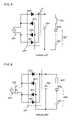
- FIG. 6shows an exemplary circuit of a floating current source of the LED lighting device of FIG. 1 .
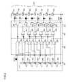
- FIG. 7is a schematic block diagram of an LED lighting device having a parallel arrangement of LEDs according to a second embodiment of the present invention.
- FIG. 8is a schematic drawing showing an LED lighting device according to prior art.
- FIG. 9is a schematic drawing showing another LED lighting device according to prior art.
- FIG. 10is a schematic drawing showing further another LED lighting device according to prior art.
- FIG. 3is a schematic block diagram for explaining an operation of one embodiment of the present invention.
- a rectified voltage V iis applied to an LED array having series-connected N number of LEDs (LED 0 to LED N ⁇ 1 : N is properly determined depending on the embodiment requirements) to drive the LEDs.
- Each of SW 0 to SW N ⁇ 1is an on/off switch of a driving current to a corresponding LED.
- a switchWhen a switch is on, an anode and a cathode of a corresponding LED are short-circuited so that no current flows across that LED.
- the switchis off, a current flows across the corresponding LED to light the LED. This on-off of switch is controlled by a switch control circuit 10 .
- the switch control circuit 10preferably controls the switches to light such a maximum number of LEDs that can be lit up by a rectified voltage generated at any given point in time in order to efficiently utilize a power source.
- a maximum number of LEDs that can be driven by a rectified voltage applied at a given timeis k (0 ⁇ k ⁇ N)
- the switch control circuit 10controls SW 0 to SW N ⁇ 1 so as to flow a current to k number of LEDs.
- any of k number of switchesmay be turned off. For example, SW 0 to SW k ⁇ 1 are turned off and other switches are turned on (in this case, if more number of switches than k are turned off, all the LEDs are not lit).
- VREF 0 , VREF 1 , VREF 2 , . . . VREF N ⁇ 2 , and VREF N ⁇ 1represent N number of reference voltages different from each other, and they satisfy VREF 0 ⁇ VREF 1 ⁇ VREF 2 ⁇ . . . ⁇ VREF N ⁇ 2 , ⁇ VREF N ⁇ 1 .
- these reference voltagesare set so that a maximum number of drivable LEDs is, for example, 1, 2, . . . , or N ⁇ 1, respectively. In practice, these reference voltages can be determined based on a forward voltage of each LED.
- the number of LEDs to be litis determined in the same manner. However, in this case, as the rectified voltage decreases, the number of LEDs to be lit decreases step-by-step from N depending on the intersection of each reference voltage and a rectified voltage.
- FIG. 5is used to explain how the lighting/lighting-out conditions of five LEDs connected in series in an LED array are controlled and changed as the rectified voltage changes.
- a floating current sourceis for limiting a current to the LED array.
- the floating current sourcehas a voltage input of from 0 (minimum) to V PEAK (maximum) in a voltage range of full-wave rectified AC input, that is, a voltage range of rectified voltage.
- DMOS gates connected to “ON” linesare driven so that DMOSs are in an ON state, while DMOS gates connected to “OFF” lines have zero volts and are in an OFF state.
- an LED connected to each DMOSis lit out or lit up (LED with a white space is lit up and LED with solid black is lit out).
- Source and drain of an on-state DMOS hereinhave a voltage close to zero. This indicates that it is not necessary to apply a high source voltage as a voltage for such DMOS gate, which is very important for DMOS safe operation. That is, the DMOS gate can be turned on/off with a low voltage, and a high voltage occurs only between source and drain of an off-state DMOS. In such a constitution, a high rectified voltage increases off-state DMOSs, and therefore a voltage applied to DMOSs are divided for many off-state DMOSs connected in series, so that each off-state DMOS has a smaller source-drain voltage of each off-state DMOS decreases. In the constitution shown in the figure, each DMOS source-drain voltage is clamped by a forward voltage of a corresponding LED.
- an LED arrayhas more number of series-connected LEDs for minimizing a power loss at a floating current source and optimizing efficiency in use of rectified voltage.
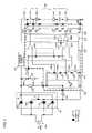
- FIG. 1is a schematic block diagram of an LED lighting device according to the first embodiment of the present invention.
- An AC source 100 and a rectifier circuit 101 in FIG. 1may be similar to those of conventional constitutions shown in FIGS. 8 to 10 .
- a commercial sourcehaving, for example, 100V to 220V and 50 Hz to 60 Hz
- an AC source other than a commercial sourcemay be used.
- Use of a single-phase AC sourceis assumed in this embodiment, but three-phase AC, etc. may be used as the source.
- Numeral 101denotes a full-wave rectifier circuit comprised of four rectified diodes 101 1 , 101 2 , 101 3 , and 101 4 , which rectifies a commercial AC source to output a rectified voltage waveform, as exemplified in FIG. 4 , between a plus output terminal A and a minus output terminal B.
- Numeral 102denotes a floating current source connected to the plus output terminal A of the full-wave rectifier circuit 101 for controlling an amount of the current flowing through an LED array 103 , the constitution and operation of which will be described below.
- Numeral 103denotes an LED array wherein N+1 number of high-intensity LEDs 103 0 to 103 N are connected in series. Among these LEDs, N number of LEDs 103 0 to 103 N ⁇ 1 are controlled to be lit or short-circuited by an LED lighting control circuit in a below-described chip 200 .
- high-intensity LEDsare used for the intention to apply to a solid-state illumination apparatus, but LEDs having an ordinary intensity may be used. For simple explanation, it is assumed that all the LEDs have the same forward voltage.
- Numeral 104denotes a current-limiting resistor for limiting a current to the chip 200 .
- One terminal of the resistoris connected to the plus output terminal A of the full-wave rectifier circuit 101 and the other terminal is connected to a power terminal (VCC) of an IC chip.
- the other terminalis also connected to a holding capacitor 106 and a cathode of a Zener diode 201 , which are described below.
- Numeral 105denotes a voltage divider connected between output terminals A and B of the rectifier circuit 101 for dividing an output voltage (rectified voltage) of the rectifier circuit 101 by resistors 105 1 and 105 2 and supplying the divided voltage to a terminal V SENSE of the chip 200 .
- This voltage divisionis for adapting the voltage to voltage endurance characteristics of the IC chip of the LED lighting control circuit 200 described below.
- Resistance values of the resistors 105 1 and 105 2are determined so as to fall within such a voltage range that the LED lighting control circuit in the chip 200 can deal with as an input voltage at the V SENSE terminal (the resistance values of the resistors 105 1 and 105 2 can be set to 135 kohm and 5 kohm so that a voltage at the V SENSE terminal is 5 V when the plus output terminal A has a peak voltage of 140 V).
- Numeral 106denotes a holding capacitor connected to the minus output terminal B of the full-wave rectifier circuit 101 .
- the holding capacitorworks together with the Zener diode 201 to supply a stable DC voltage to the chip power terminal VCC.
- the holding capacitor 106is connected in parallel to the Zener diode 201 .
- An exemplary voltage value at the chip power terminal VCCis 5 V and the holding capacitor has a capacity of, for example, 0.1 ⁇ F.
- a section 200 enclosed by a bold broken lineis one chip carrying the LED lighting control circuit (hereafter simply referred to as control circuit), which will be described below.
- the circuitoperates to selectively control lighting or short-circuit of each LED in the LED array 103 , in response to the magnitude of voltage at the terminal VSENSE, or the magnitude of AC power voltage.
- the chip 200is also referred to as a control circuit 200 .
- Numeral 202denotes a reference resistor row for generating a plurality of different reference voltages, which is comprised of N+1 number of series-connected resistors 202 0 to 202 N .
- the reference resistor row 202is provided between the chip power terminal VCC and a ground terminal GND, in which the most upper resistor 202 N is connected to the power terminal VCC and the most bottom resistor 202 0 is connected to the ground terminal GND.
- Each reference voltageis obtained as a voltage between two adjacent resistors in the reference resistor row 202 .
- Each resistorfunctions as a voltage dividing resistor for dividing a constant voltage at the terminal VCC into N number of different reference voltages Vref o , Vref 1 , . . . , Vref N ⁇ 1 . These voltages satisfy Vref 0 ⁇ Vref 1 ⁇ . . . ⁇ Vref N ⁇ 1 . It should be noted that these reference voltages are compared with voltages obtained by dividing a rectified voltage with a voltage divider, and thus these voltages are usually different from reference voltages VREF 0 to VREF N ⁇ 1 in FIG. 4 .
- Numeral 203denotes a comparator circuit, which compares a voltage applied to the terminal V SENSE (hereafter referred to as V SENSE voltage, and the magnitude thereof is described as Vd) by the voltage divider 105 with the above plurality of different reference voltages thereby to generate a comparison result signal indicative of their magnitude relation.
- the comparator circuitis comprised of N number of comparators 203 0 to 203 N ⁇ 1 .
- Each comparatordrives its output to: a low level logic when an inverting input voltage is not less than a non-inverting input voltage; and a high level logic when an inverting input voltage is less than a non-inverting input voltage.
- each comparatorhas a V SENSE voltage as an inverting input and each reference voltage as a non-inverting input.
- the most upper comparator 203 N ⁇ 1has a V SENSE voltage as an inverting input and a reference voltage Vref N ⁇ 1 , as a non-inverting voltage, at a contact point between the upper most resistor 202 N and a resistor 202 N ⁇ 1 adjacent thereto in the reference resistor row 202 .
- comparators 203 1 and 203 0have reference voltages Vref 1 and Vref 0 , as non-inverting inputs, at contact points between resistors 202 2 (not shown) and 202 1 , and 202 1 and 202 0 , respectively, in the same manner.
- Numeral 204denotes a lighting LED selection circuit, which turns on/off each switch element in a subsequent switch circuit in response to an output from the prior step of comparator circuit 203 , and thereby designates an LED of the LED array 103 to be lit up or lit out.
- this circuitis comprised of N ⁇ 1 number of two-input OR elements.
- Two inputs of an OR elementare connected to outputs of two comparators adjacent to each other in the comparator circuit.
- one input of an OR element 204 1is connected to an output of a comparator 203 1 and the other input thereof is connected to an output of a comparator 203 2 (not shown) present directly above the comparator 203 1 .
- One input of an OR element 204 0is connected to an output of the comparator 203 1 and the other input thereof to an output of a comparator 203 0 . Therefore, when one comparator has a high level output, two OR elements connected to that comparator have high level outputs.
- This connecting structureis that when attention is focused on one FET in the figure and a voltage between gate and source of that FET is controlled for the conduction (turning on) between drain and source of that FET, turning on of all the FETs below that FET in the figure can lower a gate voltage in relative to a potential of a terminal to be connected to the lowest voltage of an IC chip. This is convenient for circuit design. Further, since the IC chip exhibits voltage endurance characteristics at a relatively low voltage, this structure can reduce the risk of application of a high voltage to the IC chip.
- Numeral 205denotes a switch circuit for turning on/off a driving current to each LED in the LED array 103 , that is, for switching whether to flow a driving current to each LED for lighting or to stop a driving current to each LED for lighting out.
- This switch circuitis comprised of a plurality of switch elements, and these switch elements may be transistor switches.
- a DMOS transistorhereafter referred to as DMOS switch
- N number of DMOS switches 205 0 to 205 N ⁇ 1constitute the switch circuit.
- Each DMOS switchis connected in parallel to a corresponding LED.
- drain and source of each DMOS switch 205 0 to 205 N ⁇ 1are connected to anode and cathode of each corresponding LED 103 0 , . . . , 103 N ⁇ 1 in the LED array 103 via GND, and V 0 , . . . , V N ⁇ 2 , or V N ⁇ 1 terminal of the chip 200 .
- the uppermost DMOS switch 205 N ⁇ 1has a base directly connected to an output of the comparator 203 N ⁇ 1 , and each of other DMOS switches has a base connected to an output of each corresponding OR element.
- a DMOS switch connected to that OR elementis turned on.
- no current flows through an LED connected between drain and source of that DMOS switchresulting in lighting-out of the LED.
- This stateis equivalent to a state wherein anode and cathode of the LED is electrically short-circuited through the DMOS switch. This state is herein called “LED is short-circuited”.
- the state wherein a DMOS switch is turned off and a current flows through an LEDis herein called “LED is lit up”.
- the control circuit 200controls lighting/short-circuit of seven (7) LEDs 103 0 to 103 6 , and these seven LEDs are herein called particularly “controlled LEDs”.
- each reference voltageis set in response to voltage division ratio of the voltage divider in FIG. 1 so that a maximum number of LEDs that can be lit by a rectified voltage is 1, 2, 3, 4, 5, 7, or 8 while the rectified voltage is in a range corresponding to V SENSE voltage (Vd) range of Vref 0 ⁇ Vd ⁇ Vref 1 , Vref 1 ⁇ Vd ⁇ Vref 2 , Vref 2 ⁇ Vd ⁇ Vref 3 , Vref 3 ⁇ Vd ⁇ Vref 4 , Vref 4 ⁇ Vd ⁇ Vref 5 , Vref 5 ⁇ Vd ⁇ Vref 6 , or Vref 6 ⁇ Vd.
- VdV SENSE voltage
- Vdis Vref 0 , Vref 1 , Vref 2 , Vref 3 , Vref 4 , Vref 5 , or Vref 6
- a rectified voltageis the lowest voltage among such voltages that can light up 1, 2, 3, 4, 5, 6, or 8 LEDs at maximum when no LEDs of the LED array 103 are short-circuited.
- a rectified voltage corresponding to the range of Vref 5 ⁇ Vd ⁇ Vref 6can light up at maximum of 7 LEDs.
- FIG. 2enables lighting of 6 LEDs when Vref 5 ⁇ Vd ⁇ Vref 6 .
- the maximum number of LEDs that can be lit upis identical with the number of LEDs that are practically lit up. Therefore, this constitution can always light up the maximum number of LEDs that can be lit up by a rectified voltage at any given point in time.
- the embodimentis described based on a lighting LED selection circuit 204 having the constitution shown in FIG. 2 .
- V SENSE voltage (Vd)when V SENSE voltage (Vd) is lower than Vref 0 , the device operates as follows. Since V SENSE voltage (Vd) is smaller than all the reference voltages, all the comparators have high level outputs. Therefore, all the DMOS switches are turned on, and all the LEDs 103 0 to 103 6 are short-circuited. Further, a rectified voltage at this time is not enough to drive even one LED. Consequently, all the LEDs including the uppermost LED 103 7 are not lit up.
- V SENSE voltage (Vd)when V SENSE voltage (Vd) is not lower than Vref 0 and lower than Vref 1 , the outputs of comparators 203 0 and 203 1 are at low level and high level, respectively.
- One input of OR element 204 0is connected to the high level output of the comparator 203 1 , and thus DMOS switches 205 0 and 205 1 are both turned on. Therefore, LED 103 0 and 103 1 are short-circuited and not lit up.
- V SENSE voltage (Vd)is lower than any reference voltage of Vref 1 and voltages higher than Vref 1 , and thus all of the comparator 203 1 and ones existing upwardly therefrom have high level outputs. Therefore, all of the controlled LEDs are short-circuited and only one LED 103 7 , the uppermost one, is lit up.
- V SENSE voltage (Vd)when V SENSE voltage (Vd) is not lower than Vref 1 and lower than Vref 2 , the device operates as follows.
- the outputs of comparators 203 0 and 203 1are both at low level, and the outputs of the comparator 203 2 and ones existing upwardly therefrom are all at high level. Therefore, the output of OR element 204 0 is at low level and the outputs of OR elements other than that are at high level.
- only DMOS switch 205 0is turned off, so that only LED 103 0 among controlled LEDs is not short-circuited. Therefore, in this case, two LEDs, the uppermost LED 103 7 and LED 103 0 , light up.
- Vref 2⁇ Vd ⁇ Vref 3
- Vref 3⁇ Vd ⁇ Vref 4
- Vref 4⁇ Vd ⁇ Vref 5
- Vref 5⁇ Vd ⁇ Vref 6
- the number of LEDs that light upis 3, 4, 5, or 6, respectively.
- Vdis not lower than Vref 6
- Vdis higher than all the reference voltages and the outputs of all the comparators are at low level.
- all the DMOS switchesare turned off and all of eight (8) LEDs including the uppermost LED 103 7 light up.
- Vdgoes up to be Vref k (0 ⁇ k ⁇ 5) or more, the number of LEDs that light up when Vd reaches to Vref k is (k+1) at maximum (when reaches to Vref 6 , the number is 8).
- Vdgoes down to be Vref k (0 ⁇ k ⁇ 6) or less, the number of LEDs that light up when Vd becomes lower than Vref k is k at maximum.
- the floating current source 102 in FIG. 1prevents the flow of a current having a certain value or more to the LED array (therefore, the floating current source 102 has overcurrent protection function).
- One terminal of the resistor R 2is connected to a collector of the transistor Q 1 , and the other terminal thereof is connected to a base of the transistor Q 1 and a collector of the transistor Q 2 .
- the base and emitter of the transistor Q 1are connected to the collector and base of the transistor Q 2 , respectively.
- One terminal of the resistor R 1is connected to the emitter of the transistor Q 1 and the base of the transistor Q 2 , while the other terminal is connected to the emitter of the transistor Q 2 .
- the LED array 103is connected to a connection point between the emitter of the transistor Q 2 and the resistor R 1 .
- a rectified voltage Vrec at a plus output terminal A ( FIG. 1 ) of the rectifier circuit 101is applied to the collector of the transistor Q 1 and to the base of the transistor Q 1 via the resistor R 2 .
- Application of Vrecsupplies a base current to the transistor Q 1 via R 2 to turn on the transistor Q 1 .
- an increase of the current flowing through the resistor R 1enables a voltage applied to the resistor R 1 to be equal to a voltage V BE between the base and the emitter of the transistor Q 2 , and the transistor Q 2 is turned on and a base current of the transistor Q 1 decreases to turn off the transistor Q 1 .
- the current flowing through the LED array 103is limited to at most V BE /r 1 . This can prevent an increase of power loss caused by flowing of a current with a certain value or larger to the LED array.
- the total sum of forward voltages of LEDs to be lit in the LED array 103is as approximated to an input voltage Vrec of the floating current source at that time as possible to minimize a voltage drop at Q 1 , thus attempting to obtain higher power efficiency. Further, such operation allows the floating current source to be formed by low-cost and low-voltage devices.
- the present inventioncan light the maximum number of LEDs that can be lit by a rectified voltage at any given point in time, and therefore it is possible to minimize a voltage drop of the floating current source over the entire period of rectified voltage waveform.
- FIG. 7a second embodiment of the present invention is described by referring to FIG. 7 .
- This embodimenthas a constitution equivalent to one shown in FIG. 1 except that LEDs are arranged in parallel and a lighting LED selection circuit 204 and a switch circuit 205 are modified to a control logic circuit 204 ′ and a switch circuit 205 ′.
- the remaining parts of this embodimentare the same as those shown in FIG. 1 .
- LEDs 103 ′ 0-1 to 103 ′ (N ⁇ 1) ⁇ 3are divided into N number of blocks each having three LEDs as indicated by dotted frames. These blocks include block 0 comprised of 103 ′ 0-1 , 103 ′ 0-2 , and 103 ′ 0-3 ; block 1 comprised of 103 ′ 1-1 , 103 ′ 1-2 , and 103 ′ 1-3 ; likewise, block 2 , block 3 , . . . , block (N ⁇ 2); and finally block (N ⁇ 1) comprised of 103 ′ (N ⁇ 1) ⁇ 1 , 103 ′ (N ⁇ 1) ⁇ 2 , and 103 ′ (N ⁇ 1) ⁇ 3 .
- Nrepresents an integer of not less than 1, which can be properly set depending on embodiment requirement.
- LEDs of each blockare connected to corresponding FETs (field effect transistors 205 ′ 0-1 to 205 ′ (N ⁇ 1) ⁇ 3 ) as shown in the figure.
- FETsfield effect transistors 205 ′ 0-1 to 205 ′ (N ⁇ 1) ⁇ 3
- FETsare used instead of DMOSs in FIG. 7 , but, needless to say, DMOSs and other transistors may be used.
- the number of constitutions with series-connected FETs and LEDsis two, but this number may be properly determined depending on embodiment requirement.
- the LED 103 ′ 0-1is connected between source and drain of an FET 205 ′ 0-1 via terminals GND and V 2 .
- LEDs 103 ′ 0-2 and 103 ′ 0-3are connected in series to FETs 205 ′ 0-2 and 205 ′ 0-3 via germinal V 0 and V 1 , respectively.
- a structure of series-connected LED 103 ′ 0-2 and FET 205 ′ 0-2 , and a structure of series-connected LED 103 ′ 0-3 and FET 205 ′ 0-3are connected in parallel to FET 205 ′ 0-1 .
- a control signal from the control logic circuit 204 ′is input to each base of FETs 205 ′ 0-1 , 205 ′ 0-2 , and 205 ′ 0-3 , and each FET is controlled to be on or off in response to logic level of the control signal.
- each LED and the corresponding FET in the block 0is applied in the same manner to LEDs of other blocks.
- a block 1is connected in series to the block 0 , and likewise, blocks are connected in series up to a block (N ⁇ 1).
- each blockcomprises a plurality of LEDs, and FETs are connected in series to LEDs.
- the second embodimentapproximates a consumption current waveform of LED to a source voltage waveform by properly performing logic design of a control logic circuit, thus providing an advantage in harmonic suppression of power source.
- the brightnesscan be controlled by adjusting the number of lighting LEDs without efficiency degradation.
- LEDs having different electric characteristics/optical characteristicscan be used by each block and/or within each block. For example, LEDs having different colors may be used to change color tone.
- This methodcomprises the following steps 100 to 400 .
- Step 400may include a step of comparing a divided rectified voltage with a reference voltage so that the rectified voltage falls within a desired voltage range. Further, Step 400 may include a step of determining the magnitude of the rectified voltage in association with reference voltage. In other words, Step 400 may include a step of determining the magnitude of the rectified voltage by making comparison between the rectified voltage and one or a plurality of reference voltages. In this case, the number of lighting/short-circuited LEDs can be determined depending on the determined magnitude of rectified voltage. For example, when the rectified voltage is lower than the lowest reference voltage, the minimum number of LEDs are lit. As the largest reference voltage that is lower than the rectified voltage becomes higher, the number of lighting LEDs gradually increases. When the rectified voltage is higher than the highest reference voltage, the maximum number of LEDs are lit up.
Landscapes
- Circuit Arrangement For Electric Light Sources In General (AREA)
Abstract
Description
- a step of providing an LED array comprising a plurality of series-connected LEDs (Step100)
- a step of rectifying an AC power voltage (Step200)
- a step of supplying the rectified voltage to the LED array (Step300)
- a step of determining the magnitude of the rectified voltage (Step400)
- The exemplified embodiment is configured so that a divided rectified voltage is compared with a reference voltage. However, the scope of the present invention include direct comparison between a rectified voltage and a reference voltage without the voltage division of rectified voltage. In such a constitution, it is a matter of design how to configure reference voltage generation means and comparison means between a reference voltage and a rectified voltage.
- Means for determining the magnitude range of a rectified voltage is not limited to a constitution wherein a rectified voltage is compared with one or a plurality of reference voltages. For example, lighting/short-circuit of each LED may be controlled depending on the magnitude of a difference between reference voltage and rectified voltage. Further, the magnitude of rectified voltage is measured by a known voltage detection circuit and, depending on the measured result, lighting/short-circuit of each LED may be controlled.
- In the above exemplified embodiment, it is preferable to set such a reference voltage that a maximum number of LEDs drivable by a rectified voltage at any given point in time can be lit up from a viewpoint of efficient use of power source. However, the way of setting a reference voltage is a matter of design that can be achieved in consideration of power efficiency enhancement and other embodiment requirements.
- The lighting LED selection circuit of the exemplified embodiment lights up controlled LEDs in sequence from one side to the other side of the LED array as the rectified voltage increases, while it short-circuits LEDs in a reverse direction against the above, that is in sequence from the other side to the one side as the rectified voltage decreases. However, the present invention is not limited to such a lighting sequence. For example, when the magnitude of rectified voltage is kept the same, LEDs at any location in the LED array may be short-circuited or lit up in response to increase or decrease of the rectified voltage while the number of short-circuited or lit-up LEDs is kept the same. LEDs to be short-circuited or lit up may be selected in consideration of electric characteristics/optical characteristics of LEDs.
- In some cases, increments of individual reference voltages are constant (in this case, each reference resistor has the same resistance value in the exemplified embodiment), but in the other cases, increments thereof are different. When forward voltages of individual LEDs are different, for example, it is possible to set different incremental values of reference voltage depending thereon (in other words, a part or the entire reference resistors have different resistance values in the exemplified embodiment).
- In the exemplified embodiment, one switch element is used to short-circuit/light up one LED. However, it is possible for one switch element to short-circuit/light up a plurality of LEDs. This can be achieved, for example, by connecting a plurality of LEDs in series between drain and source of each of any one or plural DMOS switches in the first embodiment.
- The rectifier circuit is not limited to a full-wave rectifier circuit, but may be other rectifier circuit such as a half-wave rectifier circuit.
- An impedance component such as a current-limiting resistor may be used instead of a floating current source. When an impedance component is used in the exemplified embodiment, the impedance component is connected in series between the plus output terminal A of the
rectifier circuit 101 and theLED array 103. - The exemplified embodiment employs a Zener diode to generate a constant voltage, but a constant voltage generation circuit with other known constitution may be employed to generate a constant voltage.
- A temperature compensation circuit may be added to the constitution of
FIG. 6 to avoid temperature influence on the floating current source. - In the exemplified embodiment, the LED lighting control circuit is described as one mounted on one chip, but not limited thereto. For example, a part or the entire of such circuit may be constituted as an individual component.
- The above embodiments present various values (resistance values, capacitance values, voltage values, etc.) simply as examples. Thus, it goes without saying that these values can be properly set depending on embodiment requirement.
- As described above, the present invention allows efficient use of an AC source in an LED lighting device, and thus is suitable for a solid state lighting device using LEDs. Particularly, the adoption of high-brightness LEDs in an LED array preferably enables substitution for a fluorescent light or an incandescent light.
Claims (13)
Applications Claiming Priority (2)
| Application Number | Priority Date | Filing Date | Title |
|---|---|---|---|
| JP2006-232786 | 2006-08-29 | ||
| JP2006232786AJP5188690B2 (en) | 2006-08-29 | 2006-08-29 | Apparatus and method for driving an LED |
Publications (2)
| Publication Number | Publication Date |
|---|---|
| US20080094000A1 US20080094000A1 (en) | 2008-04-24 |
| US7564198B2true US7564198B2 (en) | 2009-07-21 |
Family
ID=39047119
Family Applications (1)
| Application Number | Title | Priority Date | Filing Date |
|---|---|---|---|
| US11/847,273Active2028-01-30US7564198B2 (en) | 2006-08-29 | 2007-08-29 | Device and method for driving LED |
Country Status (4)
| Country | Link |
|---|---|
| US (1) | US7564198B2 (en) |
| JP (1) | JP5188690B2 (en) |
| CN (1) | CN101137261B (en) |
| DE (2) | DE102007040152B4 (en) |
Cited By (65)
| Publication number | Priority date | Publication date | Assignee | Title |
|---|---|---|---|---|
| US20090179578A1 (en)* | 2008-01-14 | 2009-07-16 | Tai-Her Yang | Bi-directional light emitting diode drive circuit in pulsed power series resonance |
| US20090179592A1 (en)* | 2008-01-14 | 2009-07-16 | Tai-Her Yang | Uni-directional light emitting diode drive circuit in pulsed power non-resonance |
| US20090179590A1 (en)* | 2008-01-14 | 2009-07-16 | Tai-Her Yang | Bi-directional light emitting diode drive circuit in pulsed power parallel resonance |
| US20090179585A1 (en)* | 2008-01-14 | 2009-07-16 | Tai-Her Yang | Uni-directional light emitting diode drvie circuit in bi-directional divided power impedance |
| US20090179594A1 (en)* | 2008-01-14 | 2009-07-16 | Tai-Her Yang | Bi-directional light emitting diode drive circuit in bi-directional power parallel resonance |
| US20090224689A1 (en)* | 2008-03-07 | 2009-09-10 | Tai-Her Yang | Bipolar (dis)charging led drive method and circuit thereof |
| US20100109558A1 (en)* | 2008-11-03 | 2010-05-06 | Tong Fatt Chew | AC to DC LED illumination devices, systems and methods |
| US20100194298A1 (en)* | 2008-10-30 | 2010-08-05 | Fuji Electric Systems Co., Ltd. | Led drive device, led drive method and lighting system |
| US20100259181A1 (en)* | 2009-04-09 | 2010-10-14 | Sanyo Electric Co., Ltd. | Control circuit for light emitting device |
| US20100277082A1 (en)* | 2009-05-01 | 2010-11-04 | Reed William G | Gas-discharge lamp replacement with passive cooling |
| US20110234117A1 (en)* | 2010-03-26 | 2011-09-29 | Knapp Robert C | Solid State Device Controller |
| US20110316432A1 (en)* | 2009-02-17 | 2011-12-29 | Luminature Co., Ltd. | Power-Saving LED Lighting Apparatus |
| US20120051757A1 (en)* | 2010-08-25 | 2012-03-01 | Hiroyuki Nishino | Illuminating light communication device |
| US20120061691A1 (en)* | 2010-09-13 | 2012-03-15 | Chao-Hsing Chen | Light-emitting device |
| US20120126710A1 (en)* | 2010-11-23 | 2012-05-24 | Lin Yung Lin | Circuits and methods for driving light sources |
| US20120139447A1 (en)* | 2010-12-02 | 2012-06-07 | Hsin-Hui Cheng | Driving circuit having a power factor correction (pfc) function |
| US20120139428A1 (en)* | 2010-03-10 | 2012-06-07 | Lear Corporation Gmbh | Device for controlling an electrical load |
| US20120243562A1 (en)* | 2011-03-21 | 2012-09-27 | Soreq Nuclear Research Center | Laser Diode Driver |
| CN102740544A (en)* | 2011-04-13 | 2012-10-17 | 乾坤科技股份有限公司 | Driving circuit of light emitting diode with bypass circuit and driving method thereof |
| WO2012101522A3 (en)* | 2011-01-28 | 2012-11-22 | Seoul Semiconductor Co., Ltd. | Led driving circuit package |
| US20120306390A1 (en)* | 2011-06-03 | 2012-12-06 | Taiwan Semiconductor Manufacturing Company, Ltd. | Architecture for Supporting Modulized Full Operation Junction Ultra High Voltage (UHV) Light Emitting Diode (LED) Device |
| CN102932986A (en)* | 2011-08-12 | 2013-02-13 | 台湾积体电路制造股份有限公司 | Color temperature adjustment for LED lamps using switches |
| US20130221861A1 (en)* | 2010-11-02 | 2013-08-29 | Koninklijke Philips Electronics N.V. | Method and device for driving an led string |
| US20140132163A1 (en)* | 2011-07-04 | 2014-05-15 | Osram Gmbh | High-voltage led multichip module and method for adjusting an led multichip module |
| US20140159603A1 (en)* | 2012-12-07 | 2014-06-12 | Samsung Electro-Mechanics Co., Ltd. | Led driving apparatus and method |
| US8766548B2 (en) | 2008-11-03 | 2014-07-01 | Gt Biomescilt Light Limited | AC to DC LED illumination devices, systems and method |
| US8987992B2 (en) | 2009-05-20 | 2015-03-24 | Express Imaging Systems, Llc | Apparatus and method of energy efficient illumination |
| US9125261B2 (en) | 2008-11-17 | 2015-09-01 | Express Imaging Systems, Llc | Electronic control to regulate power for solid-state lighting and methods thereof |
| US9131552B2 (en) | 2012-07-25 | 2015-09-08 | Express Imaging Systems, Llc | Apparatus and method of operating a luminaire |
| US20150289341A1 (en)* | 2014-04-07 | 2015-10-08 | Dongbu Hitek Co., Ltd. | Light Emitting Device Driving Apparatus and Illumination System Including the Same |
| US9185777B2 (en) | 2014-01-30 | 2015-11-10 | Express Imaging Systems, Llc | Ambient light control in solid state lamps and luminaires |
| US9204523B2 (en) | 2012-05-02 | 2015-12-01 | Express Imaging Systems, Llc | Remotely adjustable solid-state lamp |
| US9210759B2 (en) | 2012-11-19 | 2015-12-08 | Express Imaging Systems, Llc | Luminaire with ambient sensing and autonomous control capabilities |
| US9210751B2 (en) | 2012-05-01 | 2015-12-08 | Express Imaging Systems, Llc | Solid state lighting, drive circuit and method of driving same |
| US9288873B2 (en) | 2013-02-13 | 2016-03-15 | Express Imaging Systems, Llc | Systems, methods, and apparatuses for using a high current switching device as a logic level sensor |
| US9301365B2 (en) | 2012-11-07 | 2016-03-29 | Express Imaging Systems, Llc | Luminaire with switch-mode converter power monitoring |
| US9313847B2 (en) | 2011-03-31 | 2016-04-12 | Koninklijke Philips N.V. | LED light source |
| US9360198B2 (en) | 2011-12-06 | 2016-06-07 | Express Imaging Systems, Llc | Adjustable output solid-state lighting device |
| US9414449B2 (en) | 2013-11-18 | 2016-08-09 | Express Imaging Systems, Llc | High efficiency power controller for luminaire |
| US9445485B2 (en) | 2014-10-24 | 2016-09-13 | Express Imaging Systems, Llc | Detection and correction of faulty photo controls in outdoor luminaires |
| US9462662B1 (en) | 2015-03-24 | 2016-10-04 | Express Imaging Systems, Llc | Low power photocontrol for luminaire |
| US9466443B2 (en) | 2013-07-24 | 2016-10-11 | Express Imaging Systems, Llc | Photocontrol for luminaire consumes very low power |
| US9478111B2 (en) | 2009-05-20 | 2016-10-25 | Express Imaging Systems, Llc | Long-range motion detection for illumination control |
| US9497393B2 (en) | 2012-03-02 | 2016-11-15 | Express Imaging Systems, Llc | Systems and methods that employ object recognition |
| US9516723B2 (en) | 2010-07-14 | 2016-12-06 | General Electric Company | System and method for driving light emitting diodes |
| US9516718B2 (en) | 2011-12-29 | 2016-12-06 | Seoul Semiconductor Co., Ltd. | LED luminescence apparatus |
| US9538612B1 (en) | 2015-09-03 | 2017-01-03 | Express Imaging Systems, Llc | Low power photocontrol for luminaire |
| US9560719B2 (en) | 2011-08-31 | 2017-01-31 | Chia-Teh Chen | LED security light and LED security light control device thereof |
| US9572230B2 (en) | 2014-09-30 | 2017-02-14 | Express Imaging Systems, Llc | Centralized control of area lighting hours of illumination |
| US9648704B2 (en) | 2011-08-31 | 2017-05-09 | Chia-Teh Chen | Two-level LED security light with motion sensor |
| US9693433B2 (en) | 2012-09-05 | 2017-06-27 | Express Imaging Systems, Llc | Apparatus and method for schedule based operation of a luminaire |
| US9713228B2 (en) | 2011-04-12 | 2017-07-18 | Express Imaging Systems, Llc | Apparatus and method of energy efficient illumination using received signals |
| US9924582B2 (en) | 2016-04-26 | 2018-03-20 | Express Imaging Systems, Llc | Luminaire dimming module uses 3 contact NEMA photocontrol socket |
| US9985429B2 (en) | 2016-09-21 | 2018-05-29 | Express Imaging Systems, Llc | Inrush current limiter circuit |
| US10098212B2 (en) | 2017-02-14 | 2018-10-09 | Express Imaging Systems, Llc | Systems and methods for controlling outdoor luminaire wireless network using smart appliance |
| US10219360B2 (en) | 2017-04-03 | 2019-02-26 | Express Imaging Systems, Llc | Systems and methods for outdoor luminaire wireless control |
| US10230296B2 (en) | 2016-09-21 | 2019-03-12 | Express Imaging Systems, Llc | Output ripple reduction for power converters |
| US10568191B2 (en) | 2017-04-03 | 2020-02-18 | Express Imaging Systems, Llc | Systems and methods for outdoor luminaire wireless control |
| US10904992B2 (en) | 2017-04-03 | 2021-01-26 | Express Imaging Systems, Llc | Systems and methods for outdoor luminaire wireless control |
| US20210051782A1 (en)* | 2010-09-30 | 2021-02-18 | Signify Holding B.V. | Apparatus and methods for supplying power |
| US11212887B2 (en) | 2019-11-04 | 2021-12-28 | Express Imaging Systems, Llc | Light having selectively adjustable sets of solid state light sources, circuit and method of operation thereof, to provide variable output characteristics |
| US11234304B2 (en) | 2019-05-24 | 2022-01-25 | Express Imaging Systems, Llc | Photocontroller to control operation of a luminaire having a dimming line |
| US11317497B2 (en) | 2019-06-20 | 2022-04-26 | Express Imaging Systems, Llc | Photocontroller and/or lamp with photocontrols to control operation of lamp |
| US11375599B2 (en) | 2017-04-03 | 2022-06-28 | Express Imaging Systems, Llc | Systems and methods for outdoor luminaire wireless control |
| US12439488B2 (en) | 2022-12-09 | 2025-10-07 | Express Imaging Systems, Llc | Field adjustable output for dimmable luminaires |
Families Citing this family (170)
| Publication number | Priority date | Publication date | Assignee | Title |
|---|---|---|---|---|
| CN101617565B (en)* | 2006-11-10 | 2011-11-02 | 飞利浦固体状态照明技术公司 | Methods and apparatus for controlling series-connected leds |
| DE102007041131B4 (en)* | 2007-08-30 | 2015-07-23 | Osram Gmbh | Arrangement, use and method for driving light-emitting components |
| DE102007063879B3 (en)* | 2007-08-30 | 2016-08-18 | Osram Gmbh | Arrangement, use and method for driving light-emitting components |
| US8598799B2 (en)* | 2007-12-19 | 2013-12-03 | Epistar Corporation | Alternating current light emitting device |
| TWI495389B (en) | 2008-09-05 | 2015-08-01 | Eldolab Holding Bv | Led based lighting application |
| US8198819B2 (en)* | 2008-09-17 | 2012-06-12 | Switch Bulb Company, Inc. | 3-way LED bulb |
| US9481293B2 (en) | 2008-10-20 | 2016-11-01 | Koninklijke Philips N.V. | LED light |
| US9801243B2 (en)* | 2008-11-13 | 2017-10-24 | Philips Lighting Holding B.V. | Lighting system with a plurality of LEDs |
| CN101737643B (en)* | 2008-11-13 | 2012-02-29 | 宇威光电股份有限公司 | light emitting device |
| KR100998729B1 (en)* | 2008-11-13 | 2010-12-07 | 신무현 | LED drive circuit |
| KR100907993B1 (en)* | 2009-01-19 | 2009-07-16 | 신무현 | LED drive circuit |
| KR100971757B1 (en)* | 2009-02-17 | 2010-07-21 | 주식회사 루미네이처 | Led lighting apparatus |
| KR100971759B1 (en)* | 2009-04-02 | 2010-07-21 | 주식회사 루미네이처 | Led lighting apparatus for saving power consumption |
| KR101046081B1 (en)* | 2009-03-09 | 2011-07-01 | 삼성엘이디 주식회사 | LED lighting device |
| JP5280913B2 (en)* | 2009-03-27 | 2013-09-04 | パナソニック株式会社 | Lighting device |
| TWI411353B (en)* | 2009-04-27 | 2013-10-01 | Delta Electronics Inc | Current balance supplying circuit for multi-dc loads |
| TW201043089A (en)* | 2009-05-22 | 2010-12-01 | Advanced Connectek Inc | AC light emitting diode circuit for enhancing the power factor |
| US8410717B2 (en)* | 2009-06-04 | 2013-04-02 | Point Somee Limited Liability Company | Apparatus, method and system for providing AC line power to lighting devices |
| US8569956B2 (en) | 2009-06-04 | 2013-10-29 | Point Somee Limited Liability Company | Apparatus, method and system for providing AC line power to lighting devices |
| US7936135B2 (en)* | 2009-07-17 | 2011-05-03 | Bridgelux, Inc | Reconfigurable LED array and use in lighting system |
| JP5819830B2 (en)* | 2009-08-14 | 2015-11-24 | ワンス イノベーションズ, インコーポレーテッドOnce Innovations, Inc. | Spectral change control for dimmable ACLED lighting |
| US10264637B2 (en) | 2009-09-24 | 2019-04-16 | Cree, Inc. | Solid state lighting apparatus with compensation bypass circuits and methods of operation thereof |
| US8901845B2 (en) | 2009-09-24 | 2014-12-02 | Cree, Inc. | Temperature responsive control for lighting apparatus including light emitting devices providing different chromaticities and related methods |
| US8901829B2 (en) | 2009-09-24 | 2014-12-02 | Cree Led Lighting Solutions, Inc. | Solid state lighting apparatus with configurable shunts |
| US9713211B2 (en) | 2009-09-24 | 2017-07-18 | Cree, Inc. | Solid state lighting apparatus with controllable bypass circuits and methods of operation thereof |
| US8602579B2 (en)* | 2009-09-25 | 2013-12-10 | Cree, Inc. | Lighting devices including thermally conductive housings and related structures |
| US9285103B2 (en)* | 2009-09-25 | 2016-03-15 | Cree, Inc. | Light engines for lighting devices |
| US8777449B2 (en) | 2009-09-25 | 2014-07-15 | Cree, Inc. | Lighting devices comprising solid state light emitters |
| US9068719B2 (en)* | 2009-09-25 | 2015-06-30 | Cree, Inc. | Light engines for lighting devices |
| CN101827481B (en)* | 2009-09-29 | 2013-01-09 | 李云霄 | Alternating-current power supply LED light source drive circuit with segmented conversion input |
| DE102009047889A1 (en)* | 2009-09-30 | 2011-03-31 | Osram Opto Semiconductors Gmbh | Optoelectronic semiconductor chip and method for adapting a contact structure for the electrical contacting of an optoelectronic semiconductor chip |
| CN102083248B (en)* | 2009-11-30 | 2013-12-11 | 光明电子有限公司 | Electronic device |
| TWI423726B (en)* | 2009-12-02 | 2014-01-11 | Aussmak Optoelectronic Corp | Light-emitting device |
| KR100986815B1 (en)* | 2010-02-05 | 2010-10-13 | 신봉섭 | Constant current driving apparatus for light emitting diode |
| US9482397B2 (en) | 2010-03-17 | 2016-11-01 | Once Innovations, Inc. | Light sources adapted to spectral sensitivity of diurnal avians and humans |
| US8299724B2 (en) | 2010-03-19 | 2012-10-30 | Active-Semi, Inc. | AC LED lamp involving an LED string having separately shortable sections |
| US8456095B2 (en) | 2010-03-19 | 2013-06-04 | Active-Semi, Inc. | Reduced flicker AC LED lamp with separately shortable sections of an LED string |
| CN102196614A (en)* | 2010-03-19 | 2011-09-21 | 技领半导体(上海)有限公司 | LED light string circuit having a plurality of short strings connected as long string |
| JP5683239B2 (en)* | 2010-04-28 | 2015-03-11 | 東芝情報システム株式会社 | LED drive device |
| JP2011233450A (en)* | 2010-04-30 | 2011-11-17 | On Semiconductor Trading Ltd | Control circuit of light-emitting element |
| US8362711B2 (en)* | 2010-05-03 | 2013-01-29 | Ge Investment Co., Ltd. | AC LED apparatus |
| US8519636B2 (en)* | 2010-05-03 | 2013-08-27 | Ge Investment Co., Ltd. | AC LED apparatus |
| KR100997050B1 (en)* | 2010-05-06 | 2010-11-29 | 주식회사 티엘아이 | Led lighting system for improving linghting amount |
| US8476836B2 (en)* | 2010-05-07 | 2013-07-02 | Cree, Inc. | AC driven solid state lighting apparatus with LED string including switched segments |
| US8373358B2 (en) | 2010-05-21 | 2013-02-12 | National Semiconductor Corporation | Compact and efficient driver for multiple light emitting diodes (LEDs) |
| US9907139B2 (en)* | 2010-07-07 | 2018-02-27 | MIKPOWER, Inc. | LED controller |
| US9913338B2 (en)* | 2010-07-28 | 2018-03-06 | Epistar Corporation | Light-emitting device with temperature compensation |
| TWI473526B (en)* | 2010-08-12 | 2015-02-11 | Huizhou Light Engine Ltd | Led switch circuitry for varying input voltage source |
| US9320099B2 (en) | 2010-08-12 | 2016-04-19 | Huizhou Light Engine Ltd. | LED Switch Circuitry for Varying Input Voltage Source |
| US8947014B2 (en) | 2010-08-12 | 2015-02-03 | Huizhou Light Engine Ltd. | LED switch circuitry for varying input voltage source |
| CN102376694B (en)* | 2010-08-17 | 2015-11-25 | 晶元光电股份有限公司 | Light-emitting element with temperature compensation function |
| KR100995793B1 (en)* | 2010-08-20 | 2010-11-22 | 김남규 | Drive circuit for led array |
| KR101679763B1 (en)* | 2010-09-10 | 2016-11-25 | 오스람 실바니아 인코포레이티드 | Directly driven high efficiency LED circuit |
| DE102010047450A1 (en) | 2010-10-04 | 2012-04-05 | Osram Opto Semiconductors Gmbh | lighting device |
| TW201218851A (en)* | 2010-10-29 | 2012-05-01 | Numen Technology Inc | which can ignite different number of LED's, and can enhance the efficiency of stacked LED driving circuit |
| US8040071B2 (en)* | 2010-12-14 | 2011-10-18 | O2Micro, Inc. | Circuits and methods for driving light sources |
| US8638047B2 (en) | 2010-12-07 | 2014-01-28 | Iml International | Two-terminal current controller and related LED lighting device |
| TWI435654B (en) | 2010-12-07 | 2014-04-21 | 安恩國際公司 | Two-terminal current controller and related led lighting device |
| KR101110380B1 (en)* | 2010-12-16 | 2012-02-24 | 이동원 | AC Drive LED Lighting |
| CN102105008A (en)* | 2011-01-04 | 2011-06-22 | 罗宏基 | Load current adjusting circuit |
| US8896220B2 (en) | 2011-03-07 | 2014-11-25 | Osram Sylvania Inc. | High efficiency, low energy storage driver circuit for solid state light sources |
| EP2692207B1 (en) | 2011-03-28 | 2016-05-18 | Koninklijke Philips N.V. | Driving device and method for driving a load, in particular an led assembly |
| RU2588578C2 (en)* | 2011-03-31 | 2016-07-10 | Конинклейке Филипс Н.В. | Led light source |
| KR200463411Y1 (en) | 2011-04-01 | 2012-11-01 | 아이에스이텍 주식회사 | LED Driving Circuit for LED Lighting |
| BR112013025602A2 (en) | 2011-04-08 | 2016-12-27 | Koninkl Philips Nv | controller device for controlling a load, particularly a LED array, control method for controlling a load, particularly a LED array and lighting fixture |
| JP5720392B2 (en)* | 2011-04-14 | 2015-05-20 | 日亜化学工業株式会社 | Light emitting diode drive device |
| US20120306392A1 (en)* | 2011-06-02 | 2012-12-06 | Taiwan Semiconductor Manufacturing Company, Ltd. | Light-emitting diode network |
| US9839083B2 (en) | 2011-06-03 | 2017-12-05 | Cree, Inc. | Solid state lighting apparatus and circuits including LED segments configured for targeted spectral power distribution and methods of operating the same |
| CN102253288A (en)* | 2011-06-30 | 2011-11-23 | 迈普通信技术股份有限公司 | E1 interface impedance testing device and system |
| US9392662B2 (en)* | 2011-07-23 | 2016-07-12 | Texas Instruments Incorporated | Systems and methods of LED color overlap |
| US9131561B2 (en) | 2011-09-16 | 2015-09-08 | Cree, Inc. | Solid-state lighting apparatus and methods using energy storage |
| US8742671B2 (en)* | 2011-07-28 | 2014-06-03 | Cree, Inc. | Solid state lighting apparatus and methods using integrated driver circuitry |
| US9510413B2 (en) | 2011-07-28 | 2016-11-29 | Cree, Inc. | Solid state lighting apparatus and methods of forming |
| US9277605B2 (en) | 2011-09-16 | 2016-03-01 | Cree, Inc. | Solid-state lighting apparatus and methods using current diversion controlled by lighting device bias states |
| JP6013033B2 (en)* | 2011-08-11 | 2016-10-25 | セミコンダクター・コンポーネンツ・インダストリーズ・リミテッド・ライアビリティ・カンパニー | Light emitting element control circuit |
| CN202203727U (en)* | 2011-08-16 | 2012-04-25 | 惠州元晖光电有限公司 | Optical engine with optical switching array |
| WO2013031695A1 (en)* | 2011-08-26 | 2013-03-07 | シチズンホールディングス株式会社 | Led illumination device |
| DE102011112716A1 (en)* | 2011-09-07 | 2013-03-07 | Audi Ag | Method for operating a headlamp of a motor vehicle |
| KR101273384B1 (en)* | 2011-09-15 | 2013-06-11 | (주)포인트텍 | Apparatus for driving multi-channel light emitting diode |
| US8791641B2 (en)* | 2011-09-16 | 2014-07-29 | Cree, Inc. | Solid-state lighting apparatus and methods using energy storage |
| CN102497695A (en)* | 2011-11-18 | 2012-06-13 | 上海晶丰明源半导体有限公司 | LED linear constant current control circuit and LED linear circuit |
| CN103167680A (en)* | 2011-12-16 | 2013-06-19 | 晶锜科技股份有限公司 | Light emitting device and method of operation thereof |
| TWI449287B (en)* | 2011-12-19 | 2014-08-11 | Lextar Electronics Corp | Over voltage protection circuit and driver circuit using the same |
| US10187942B2 (en)* | 2011-12-23 | 2019-01-22 | Cree, Inc. | Methods and circuits for controlling lighting characteristics of solid state lighting devices and lighting apparatus incorporating such methods and/or circuits |
| US11178740B2 (en) | 2011-12-27 | 2021-11-16 | Ideal Industries Lighting Llc | Solid-state lighting apparatus including current diversion controlled by lighting device bias states and current limiting using a passive electrical component |
| KR101984927B1 (en)* | 2011-12-29 | 2019-06-04 | 서울반도체 주식회사 | Led driving circuit and luminescence apparatus comprising the same |
| CN102573235B (en)* | 2012-01-11 | 2013-07-24 | 矽力杰半导体技术(杭州)有限公司 | High-efficiency light-emitting diode (LED) driving circuit and driving method thereof |
| CN102595715A (en)* | 2012-01-19 | 2012-07-18 | 上海晶丰明源半导体有限公司 | Light-emitting diode (LED) linear current control circuit and LED linear circuit |
| KR101272463B1 (en)* | 2012-01-26 | 2013-06-17 | 주식회사 티엘아이 | Led lighting system with improving stability in the amount of light |
| US20140375214A1 (en)* | 2012-03-14 | 2014-12-25 | 3M Innovative Properties Company | Systems and methods for constant illumination and color control of light emission diodes in a polyphase system |
| DE102012006341B4 (en)* | 2012-03-28 | 2019-08-14 | Diehl Aerospace Gmbh | LED lighting device with LED lines and method for operating the LED lighting device |
| DE102012006316B4 (en)* | 2012-03-28 | 2014-02-13 | Diehl Aerospace Gmbh | LED dimming device with super dimming operation and method for operating the LED lighting device |
| DE102012006315B4 (en)* | 2012-03-28 | 2014-02-13 | Diehl Aerospace Gmbh | An LED lighting device for an AC power supply and method of operating the LED lighting device |
| DE102012006343B4 (en)* | 2012-03-28 | 2014-02-13 | Diehl Aerospace Gmbh | LED lighting device with control device and method for operating the LED lighting device |
| KR101175934B1 (en)* | 2012-04-02 | 2012-08-22 | 주식회사 실리콘웍스 | Led driving circuit and led lighting system of ac direct type |
| CN102665324A (en)* | 2012-04-12 | 2012-09-12 | 上海晶丰明源半导体有限公司 | LED linear driving circuit applicable to thyristor dimmer and control method |
| US9456478B2 (en)* | 2012-04-23 | 2016-09-27 | Abl Ip Holding Llc | System and method for controlling LED segments to provide lighting effects |
| KR101408027B1 (en)* | 2012-04-25 | 2014-06-17 | 아이엠엘 인터내셔널 | Two-terminal current controller and related led lighting device |
| CN102711319B (en)* | 2012-05-03 | 2015-05-06 | 李云霄 | LED (light emitting diode) light source subregion subsection transformation input driving control method and control circuit thereof |
| US9398656B2 (en)* | 2012-05-16 | 2016-07-19 | Beijing EffiLED Opto-Electronics Technology Co., Ltd. | Device and method for driving an LED light |
| US9374858B2 (en) | 2012-05-21 | 2016-06-21 | Cree, Inc. | Solid-state lighting apparatus and methods using switched energy storage |
| TWI533744B (en)* | 2012-06-13 | 2016-05-11 | 友達光電股份有限公司 | Driving circuit of light emitting diode string and driving method thereof |
| CN202759632U (en)* | 2012-06-20 | 2013-02-27 | 伟思科技控股有限公司 | A driving circuit and lighting device for a light-emitting diode |
| CN102811538A (en)* | 2012-07-24 | 2012-12-05 | 上海亚明照明有限公司 | Driving circuit for light emitting diode (LED) module |
| TWI477190B (en)* | 2012-08-10 | 2015-03-11 | Macroblock Inc | Light emitting diode driving apparatus |
| CN102858061A (en)* | 2012-08-17 | 2013-01-02 | 王知康 | LED (light-emitting diode) power supply circuit controlled by multiple sections of switches |
| CN102858062A (en)* | 2012-08-22 | 2013-01-02 | 深圳市明微电子股份有限公司 | Light emitting diode (LED) control circuit and LED illuminating device |
| TWI481304B (en)* | 2012-09-13 | 2015-04-11 | Raydium Semiconductor Corp | Led driving apparatus and operating method thereof |
| TWI481302B (en)* | 2012-09-13 | 2015-04-11 | Raydium Semiconductor Corp | Led driving apparatus and operating method thereof |
| TWI481303B (en)* | 2012-09-13 | 2015-04-11 | Raydium Semiconductor Corp | Led driving apparatus and operating method thereof |
| US9131571B2 (en) | 2012-09-14 | 2015-09-08 | Cree, Inc. | Solid-state lighting apparatus and methods using energy storage with segment control |
| CN103687151A (en)* | 2012-09-20 | 2014-03-26 | 台湾松尾股份有限公司 | Drive circuit |
| CN103716935B (en)* | 2012-09-29 | 2016-01-13 | 钰瀚科技股份有限公司 | Driver for multiple lighting units based on light-emitting diodes |
| US9220148B2 (en)* | 2012-10-08 | 2015-12-22 | Koninklijke Philips N.V. | Methods and apparatus for compensating a removal of LEDs from an LED array |
| JP5975393B2 (en) | 2012-10-29 | 2016-08-23 | パナソニックIpマネジメント株式会社 | Lighting device and lighting apparatus using the same |
| CN102892238B (en)* | 2012-10-30 | 2015-02-04 | 四川新力光源股份有限公司 | Dimming drive circuit of LED module directly driven by alternating current |
| KR20140065127A (en)* | 2012-11-21 | 2014-05-29 | 삼성디스플레이 주식회사 | Inspecting apparatus and method thereof |
| KR101439651B1 (en)* | 2012-11-26 | 2014-09-12 | 인하대학교 산학협력단 | Ac direct type led driver using pattern generator with logic gate |
| CN103025012B (en)* | 2012-12-07 | 2014-12-03 | 华南理工大学 | Light emitting diode (LED) pulse drive circuit and drive method thereof |
| TWI478622B (en)* | 2012-12-27 | 2015-03-21 | Dynascan Technology Corp | Led control circuit with self adaptive regulation |
| CN103096589A (en)* | 2013-01-04 | 2013-05-08 | 广州奥迪通用照明有限公司 | Alternating current (AC) light-emitting diode (LED) driving circuit with overvoltage protection and driving method |
| US10231300B2 (en) | 2013-01-15 | 2019-03-12 | Cree, Inc. | Systems and methods for controlling solid state lighting during dimming and lighting apparatus incorporating such systems and/or methods |
| US10264638B2 (en) | 2013-01-15 | 2019-04-16 | Cree, Inc. | Circuits and methods for controlling solid state lighting |
| CN103152911B (en)* | 2013-01-21 | 2015-02-18 | 光远科技股份有限公司 | LED control circuit with adaptive adjustment |
| TWI605730B (en)* | 2013-02-05 | 2017-11-11 | 晶元光電股份有限公司 | Light-emitting device with a temperature compensation element |
| CN103179764B (en)* | 2013-04-12 | 2016-07-06 | 广州怡泰照明电子科技有限公司 | A kind of LED with self-adaptive driving circuit and self-adaptive driving circuit |
| JP5586732B1 (en)* | 2013-04-15 | 2014-09-10 | 日本▲まき▼線工業株式会社 | LED lighting device |
| CN104135788B (en)* | 2013-05-02 | 2016-08-03 | 无锡华润华晶微电子有限公司 | A kind of constant current driver circuit for LED of tunable optical |
| KR101536108B1 (en)* | 2013-05-22 | 2015-07-13 | 주식회사 실리콘웍스 | Control circuit and voltage generating method for led lighting apparatus |
| KR101610617B1 (en)* | 2013-05-23 | 2016-04-08 | 주식회사 실리콘웍스 | Led lighting apparatus |
| KR102125245B1 (en)* | 2013-06-28 | 2020-06-22 | 주식회사 실리콘웍스 | Led lighting apparatus and control circuit thereof |
| US20150008834A1 (en)* | 2013-07-03 | 2015-01-08 | Huizhou Light Engine Limited | Lossless forward voltage matching network for led drivers |
| CN104333934B (en) | 2013-07-22 | 2016-12-28 | 四川新力光源股份有限公司 | LED lighting drive circuit |
| CN105493634B (en) | 2013-08-02 | 2019-02-01 | 万斯创新公司 | System and method for lighting livestock |
| CN103517520B (en)* | 2013-09-10 | 2014-10-29 | 深圳市晟碟半导体有限公司 | LED driving device |
| CN105792439B (en)* | 2013-09-29 | 2018-12-28 | 矽力杰半导体技术(杭州)有限公司 | LED drive circuit |
| US9603211B2 (en) | 2013-09-29 | 2017-03-21 | Silergy Semiconductor Technology (Hangzhou) Ltd | LED driver |
| CN103501562A (en) | 2013-09-29 | 2014-01-08 | 矽力杰半导体技术(杭州)有限公司 | LED drive circuit |
| US10206378B2 (en) | 2014-01-07 | 2019-02-19 | Once Innovations, Inc. | System and method of enhancing swine reproduction |
| US9247603B2 (en) | 2014-02-11 | 2016-01-26 | Once Innovations, Inc. | Shunt regulator for spectral shift controlled light source |
| US10111286B1 (en)* | 2014-02-27 | 2018-10-23 | Inter-Global, Inc. | Driver circuit for LED light |
| DE102014104365B4 (en)* | 2014-03-28 | 2015-11-26 | Vossloh-Schwabe Deutschland Gmbh | lighting device |
| US20150289327A1 (en)* | 2014-04-04 | 2015-10-08 | Lumenpulse Lighting Inc. | System and method for powering and controlling a solid state lighting unit |
| US9572212B2 (en)* | 2014-05-21 | 2017-02-14 | Lumens Co., Ltd. | LED lighting device using AC power supply |
| CN105282899B (en)* | 2014-06-17 | 2018-03-27 | 钰瀚科技股份有限公司 | Driving circuit of light emitting diode with low flicker and high power factor |
| KR102335311B1 (en)* | 2014-11-20 | 2021-12-09 | 주식회사 엘엑스세미콘 | Lighting apparatus |
| CN104575240B (en)* | 2015-01-21 | 2017-07-11 | 武汉理工大学 | Mechanical drive mode multifunction teaching platform |
| KR102256633B1 (en)* | 2015-02-06 | 2021-05-28 | 엘지이노텍 주식회사 | Apparatus of driving a light emitting device and A ligjt emitting module including the same |
| DE102015106688B4 (en)* | 2015-04-29 | 2020-03-12 | Infineon Technologies Ag | SWITCH WITH A FIELD EFFECT TRANSISTOR, ESPECIALLY IN AN INTEGRATED CIRCUIT FOR USE IN SYSTEMS WITH LOADS |
| CN105282929B (en)* | 2015-10-20 | 2018-04-27 | 晨辉光宝科技有限公司 | A kind of full voltage piece-wise linear constant current LED drive circuit of automatic switchover mode |
| MX364196B (en) | 2015-12-09 | 2019-04-16 | Abl Ip Holding Llc | Color mixing for solid state lighting using direct ac drives. |
| KR102456426B1 (en)* | 2015-12-28 | 2022-10-20 | 엘지이노텍 주식회사 | LED voltage driver circuit |
| US9681511B1 (en) | 2016-03-25 | 2017-06-13 | New Energies & Alternative Technologies, Inc. | LED driver circuits |
| US10270359B2 (en)* | 2016-03-25 | 2019-04-23 | New Energies & Alternative Technologies, Inc. | Multi-use driver circuits |
| US10772172B2 (en) | 2016-03-29 | 2020-09-08 | Signify North America Corporation | System and method of illuminating livestock |
| US9854637B2 (en) | 2016-05-18 | 2017-12-26 | Abl Ip Holding Llc | Method for controlling a tunable white fixture using a single handle |
| WO2017209655A1 (en)* | 2016-06-03 | 2017-12-07 | Юрий Борисович СОКОЛОВ | Powerful led illuminator controlled by a controller |
| US9681504B1 (en) | 2016-06-14 | 2017-06-13 | New Energies & Alternative Technologies, Inc. | Driver circuits with multiple rectifiers |
| CN105939559B (en)* | 2016-07-08 | 2018-02-23 | 易美芯光(北京)科技有限公司 | A kind of low frequency dodges AC LED circuit |
| US9913325B1 (en)* | 2017-02-03 | 2018-03-06 | Semiconductor Components Industries, Llc | LED direct AC drive circuit |
| CN107172755B (en)* | 2017-06-27 | 2019-04-16 | 深圳创维-Rgb电子有限公司 | A kind of LED light bar network current foldback circuit, driving power and television set |
| US10271394B1 (en) | 2017-12-29 | 2019-04-23 | MIKPOWER, Inc. | LED controller |
| US10314122B1 (en) | 2018-04-18 | 2019-06-04 | Diodes Incorporated | Constant current linear driver with high power factor |
| TWI669985B (en)* | 2018-10-12 | 2019-08-21 | 力林科技股份有限公司 | Light emitting diode driving device and light emitting diode backlight module |
| KR102034981B1 (en)* | 2019-03-04 | 2019-10-22 | 매그나칩 반도체 유한회사 | Led driver circuit and light apparatus having the same in |
| US10874006B1 (en) | 2019-03-08 | 2020-12-22 | Abl Ip Holding Llc | Lighting fixture controller for controlling color temperature and intensity |
| US10728979B1 (en) | 2019-09-30 | 2020-07-28 | Abl Ip Holding Llc | Lighting fixture configured to provide multiple lighting effects |
| CN112804781A (en)* | 2019-11-13 | 2021-05-14 | 上海路傲电子科技有限公司 | Control circuit, drive circuit, control method and lighting device |
| CN111867179A (en)* | 2020-08-11 | 2020-10-30 | 深圳市嘉润原新显科技有限公司 | Audio Light Controllers, Audio Lights, and Displays |
| US11778715B2 (en) | 2020-12-23 | 2023-10-03 | Lmpg Inc. | Apparatus and method for powerline communication control of electrical devices |
Citations (2)
| Publication number | Priority date | Publication date | Assignee | Title |
|---|---|---|---|---|
| US7081722B1 (en)* | 2005-02-04 | 2006-07-25 | Kimlong Huynh | Light emitting diode multiphase driver circuit and method |
| US20070290625A1 (en)* | 2006-06-15 | 2007-12-20 | Patent-Treuhand-Gesellschaft Fur Elektrische Gluhlampen Mbh | Driver arrangement for led lamps |
Family Cites Families (16)
| Publication number | Priority date | Publication date | Assignee | Title |
|---|---|---|---|---|
| JPH0575166A (en)* | 1991-09-17 | 1993-03-26 | Mitsubishi Electric Corp | LED drive circuit |
| JPH1167471A (en)* | 1997-08-26 | 1999-03-09 | Tec Corp | Lighting equipment |
| JP3445540B2 (en)* | 1999-11-16 | 2003-09-08 | 常盤電業株式会社 | Power circuit |
| DE20101418U1 (en)* | 2001-01-26 | 2001-05-17 | Insta Elektro GmbH & Co KG, 58511 Lüdenscheid | Circuit arrangement for operating several lamps |
| JP3082719U (en)* | 2001-06-15 | 2001-12-26 | 舶用電球株式会社 | LED lamp |
| JP2003188415A (en)* | 2001-12-18 | 2003-07-04 | Asahi Matsushita Electric Works Ltd | LED lighting device |
| US6768047B2 (en)* | 2002-06-13 | 2004-07-27 | Koninklijke Philips Electronics N.V. | Autonomous solid state lighting system |
| CN2620959Y (en)* | 2003-03-07 | 2004-06-16 | 赵文兴 | A New Lamp Body Control and Protection Circuit of Light Emitting Diode |
| US6989807B2 (en) | 2003-05-19 | 2006-01-24 | Add Microtech Corp. | LED driving device |
| EP2079276B1 (en)* | 2003-08-27 | 2018-10-10 | Osram Sylvania, Inc. | Driver circuit for LED vehicle lamp |
| GB0407574D0 (en)* | 2004-04-03 | 2004-05-05 | Oxley Dev Co Ltd | Method and drive circuit for controlling leds |
| US7633463B2 (en)* | 2004-04-30 | 2009-12-15 | Analog Devices, Inc. | Method and IC driver for series connected R, G, B LEDs |
| CN2713284Y (en)* | 2004-07-12 | 2005-07-27 | 黄元刚 | LED illuminating lamp |
| JP4581646B2 (en)* | 2004-11-22 | 2010-11-17 | パナソニック電工株式会社 | Light emitting diode lighting device |
| EP1825717B1 (en)* | 2004-11-23 | 2014-01-08 | Koninklijke Philips N.V. | Apparatus and method for controlling colour and colour temperature of light generated by a digitally controlled luminaire |
| JP5099661B2 (en)* | 2005-10-28 | 2012-12-19 | 株式会社寺田電機製作所 | LED driving circuit and LED driving method |
- 2006
- 2006-08-29JPJP2006232786Apatent/JP5188690B2/ennot_activeExpired - Fee Related
- 2007
- 2007-08-24DEDE102007040152.5Apatent/DE102007040152B4/enactiveActive
- 2007-08-24DEDE102007063965.3Apatent/DE102007063965B3/enactiveActive
- 2007-08-29USUS11/847,273patent/US7564198B2/enactiveActive
- 2007-08-29CNCN2007101425850Apatent/CN101137261B/ennot_activeExpired - Fee Related
Patent Citations (2)
| Publication number | Priority date | Publication date | Assignee | Title |
|---|---|---|---|---|
| US7081722B1 (en)* | 2005-02-04 | 2006-07-25 | Kimlong Huynh | Light emitting diode multiphase driver circuit and method |
| US20070290625A1 (en)* | 2006-06-15 | 2007-12-20 | Patent-Treuhand-Gesellschaft Fur Elektrische Gluhlampen Mbh | Driver arrangement for led lamps |
Cited By (109)
| Publication number | Priority date | Publication date | Assignee | Title |
|---|---|---|---|---|
| US20090179578A1 (en)* | 2008-01-14 | 2009-07-16 | Tai-Her Yang | Bi-directional light emitting diode drive circuit in pulsed power series resonance |
| US8049440B2 (en)* | 2008-01-14 | 2011-11-01 | Tai-Her Yang | Uni-directional light emitting diode drive circuit in pulsed power non-resonance |
| US20090179590A1 (en)* | 2008-01-14 | 2009-07-16 | Tai-Her Yang | Bi-directional light emitting diode drive circuit in pulsed power parallel resonance |
| US20090179585A1 (en)* | 2008-01-14 | 2009-07-16 | Tai-Her Yang | Uni-directional light emitting diode drvie circuit in bi-directional divided power impedance |
| US20090179594A1 (en)* | 2008-01-14 | 2009-07-16 | Tai-Her Yang | Bi-directional light emitting diode drive circuit in bi-directional power parallel resonance |
| US8063582B2 (en)* | 2008-01-14 | 2011-11-22 | Tai-Her Yang | Uni-directional light emitting diode drvie circuit in bi-directional divided power impedance |
| US8063587B2 (en)* | 2008-01-14 | 2011-11-22 | Tai-Her Yang | Bi-directional light emitting diode drive circuit in bi-directional power parallel resonance |
| US8058814B2 (en)* | 2008-01-14 | 2011-11-15 | Tai-Her Yang | Bi-directional light emitting diode drive circuit in pulsed power series resonance |
| US20090179592A1 (en)* | 2008-01-14 | 2009-07-16 | Tai-Her Yang | Uni-directional light emitting diode drive circuit in pulsed power non-resonance |
| US8067901B2 (en)* | 2008-01-14 | 2011-11-29 | Tai-Her Yang | Bi-directional light emitting diode drive circuit in pulsed power parallel resonance |
| US20090224689A1 (en)* | 2008-03-07 | 2009-09-10 | Tai-Her Yang | Bipolar (dis)charging led drive method and circuit thereof |
| US8054004B2 (en)* | 2008-03-07 | 2011-11-08 | Tai-Her Yang | Bipolar (dis)charging LED drive method and circuit thereof |
| US8164276B2 (en)* | 2008-10-30 | 2012-04-24 | Fuji Electric Co., Ltd. | LED drive device, LED drive method and lighting system |
| US20100194298A1 (en)* | 2008-10-30 | 2010-08-05 | Fuji Electric Systems Co., Ltd. | Led drive device, led drive method and lighting system |
| US8035307B2 (en)* | 2008-11-03 | 2011-10-11 | Gt Biomescilt Light Limited | AC to DC LED illumination devices, systems and methods |
| US8766548B2 (en) | 2008-11-03 | 2014-07-01 | Gt Biomescilt Light Limited | AC to DC LED illumination devices, systems and method |
| US20100109558A1 (en)* | 2008-11-03 | 2010-05-06 | Tong Fatt Chew | AC to DC LED illumination devices, systems and methods |
| US9125261B2 (en) | 2008-11-17 | 2015-09-01 | Express Imaging Systems, Llc | Electronic control to regulate power for solid-state lighting and methods thereof |
| US9967933B2 (en) | 2008-11-17 | 2018-05-08 | Express Imaging Systems, Llc | Electronic control to regulate power for solid-state lighting and methods thereof |
| US20110316432A1 (en)* | 2009-02-17 | 2011-12-29 | Luminature Co., Ltd. | Power-Saving LED Lighting Apparatus |
| US8400082B2 (en)* | 2009-02-17 | 2013-03-19 | Luminature Co., Ltd. | Power-saving LED lighting apparatus |
| US20100259181A1 (en)* | 2009-04-09 | 2010-10-14 | Sanyo Electric Co., Ltd. | Control circuit for light emitting device |
| US8330380B2 (en)* | 2009-04-09 | 2012-12-11 | Semiconductor Components Industries, Llc | Control circuit for light emitting device |
| US20100277082A1 (en)* | 2009-05-01 | 2010-11-04 | Reed William G | Gas-discharge lamp replacement with passive cooling |
| US8926139B2 (en) | 2009-05-01 | 2015-01-06 | Express Imaging Systems, Llc | Gas-discharge lamp replacement with passive cooling |
| US8987992B2 (en) | 2009-05-20 | 2015-03-24 | Express Imaging Systems, Llc | Apparatus and method of energy efficient illumination |
| US9478111B2 (en) | 2009-05-20 | 2016-10-25 | Express Imaging Systems, Llc | Long-range motion detection for illumination control |
| US20120139428A1 (en)* | 2010-03-10 | 2012-06-07 | Lear Corporation Gmbh | Device for controlling an electrical load |
| US8994278B2 (en)* | 2010-03-10 | 2015-03-31 | Lear Corporation Gmbh | Device for controlling an electrical load |
| US20110234117A1 (en)* | 2010-03-26 | 2011-09-29 | Knapp Robert C | Solid State Device Controller |
| US8354802B2 (en) | 2010-03-26 | 2013-01-15 | Bgbk, Llc | Solid state device controller |
| US9516723B2 (en) | 2010-07-14 | 2016-12-06 | General Electric Company | System and method for driving light emitting diodes |
| US9451679B2 (en)* | 2010-08-25 | 2016-09-20 | Panasonic Intellectual Property Management Co., Ltd. | Illuminating light communication device |
| US20120051757A1 (en)* | 2010-08-25 | 2012-03-01 | Hiroyuki Nishino | Illuminating light communication device |
| TWI595629B (en)* | 2010-09-13 | 2017-08-11 | 晶元光電股份有限公司 | Illuminating device |
| CN102403440A (en)* | 2010-09-13 | 2012-04-04 | 晶元光电股份有限公司 | light emitting device |
| US20120061691A1 (en)* | 2010-09-13 | 2012-03-15 | Chao-Hsing Chen | Light-emitting device |
| US9035329B2 (en)* | 2010-09-13 | 2015-05-19 | Epistar Corporation | Light-emitting device |
| US11690151B2 (en)* | 2010-09-30 | 2023-06-27 | Signify Holding B.V. | Apparatus and methods for supplying power |
| US20210051782A1 (en)* | 2010-09-30 | 2021-02-18 | Signify Holding B.V. | Apparatus and methods for supplying power |
| US20130221861A1 (en)* | 2010-11-02 | 2013-08-29 | Koninklijke Philips Electronics N.V. | Method and device for driving an led string |
| US9030121B2 (en)* | 2010-11-23 | 2015-05-12 | O2Micro, Inc. | Circuits and methods for driving light sources |
| US20120126710A1 (en)* | 2010-11-23 | 2012-05-24 | Lin Yung Lin | Circuits and methods for driving light sources |
| US8581509B2 (en)* | 2010-12-02 | 2013-11-12 | U-Tel Technology Co., Ltd. | Driving circuit having a power factor correction (PFC) function |
| US20120139447A1 (en)* | 2010-12-02 | 2012-06-07 | Hsin-Hui Cheng | Driving circuit having a power factor correction (pfc) function |
| WO2012101522A3 (en)* | 2011-01-28 | 2012-11-22 | Seoul Semiconductor Co., Ltd. | Led driving circuit package |
| US8599891B2 (en)* | 2011-03-21 | 2013-12-03 | Soreq Nuclear Research Center | Laser diode driver |
| US20120243562A1 (en)* | 2011-03-21 | 2012-09-27 | Soreq Nuclear Research Center | Laser Diode Driver |
| US9313847B2 (en) | 2011-03-31 | 2016-04-12 | Koninklijke Philips N.V. | LED light source |
| US9713228B2 (en) | 2011-04-12 | 2017-07-18 | Express Imaging Systems, Llc | Apparatus and method of energy efficient illumination using received signals |
| CN102740544A (en)* | 2011-04-13 | 2012-10-17 | 乾坤科技股份有限公司 | Driving circuit of light emitting diode with bypass circuit and driving method thereof |
| CN102740544B (en)* | 2011-04-13 | 2015-06-17 | 乾坤科技股份有限公司 | Driving circuit of light emitting diode with bypass circuit and driving method thereof |
| US20120306390A1 (en)* | 2011-06-03 | 2012-12-06 | Taiwan Semiconductor Manufacturing Company, Ltd. | Architecture for Supporting Modulized Full Operation Junction Ultra High Voltage (UHV) Light Emitting Diode (LED) Device |
| US20140132163A1 (en)* | 2011-07-04 | 2014-05-15 | Osram Gmbh | High-voltage led multichip module and method for adjusting an led multichip module |
| US9018846B2 (en) | 2011-08-12 | 2015-04-28 | Gt Biomescilt Light Limited | AC to DC LED illumination devices, systems and methods |
| CN102932986A (en)* | 2011-08-12 | 2013-02-13 | 台湾积体电路制造股份有限公司 | Color temperature adjustment for LED lamps using switches |
| CN102932986B (en)* | 2011-08-12 | 2016-02-03 | 晶元光电股份有限公司 | Color temperature adjustment of LED lamps using switches |
| US9743480B2 (en) | 2011-08-31 | 2017-08-22 | Chia-Teh Chen | Two-level LED security light with motion sensor |
| US11893868B2 (en) | 2011-08-31 | 2024-02-06 | Vaxcel International Co., Ltd. | Multi-level LED security light with motion sensor |
| US9648704B2 (en) | 2011-08-31 | 2017-05-09 | Chia-Teh Chen | Two-level LED security light with motion sensor |
| US10326301B2 (en) | 2011-08-31 | 2019-06-18 | Vaxcel International Co., Ltd. | Two-level LED security light with motion sensor |
| US10225902B2 (en) | 2011-08-31 | 2019-03-05 | Vaxcel International Co., Ltd. | Two-level security light with motion sensor |
| US10516292B2 (en) | 2011-08-31 | 2019-12-24 | Vaxcel International Co., Ltd. | Two-level LED security light with motion sensor |
| US10763691B2 (en) | 2011-08-31 | 2020-09-01 | Vaxcel International Co., Ltd. | Two-level LED security light with motion sensor |
| US9826590B2 (en) | 2011-08-31 | 2017-11-21 | Chia-Teh Chen | Two-level LED security light with motion sensor |
| US10770916B2 (en) | 2011-08-31 | 2020-09-08 | Vaxcel International Co., Ltd. | Two-level LED security light with motion sensor |
| US10491032B2 (en) | 2011-08-31 | 2019-11-26 | Vaxcel International Co., Ltd. | Lifestyle security light |
| US9560719B2 (en) | 2011-08-31 | 2017-01-31 | Chia-Teh Chen | LED security light and LED security light control device thereof |
| US11183039B2 (en) | 2011-08-31 | 2021-11-23 | Vaxcel International Co., Ltd. | Two-level LED security light with motion sensor |
| US11657691B2 (en) | 2011-08-31 | 2023-05-23 | Vaxcel International Co., Ltd. | Two-level LED security light with motion sensor |
| US9360198B2 (en) | 2011-12-06 | 2016-06-07 | Express Imaging Systems, Llc | Adjustable output solid-state lighting device |
| US9516718B2 (en) | 2011-12-29 | 2016-12-06 | Seoul Semiconductor Co., Ltd. | LED luminescence apparatus |
| US9713213B2 (en) | 2011-12-29 | 2017-07-18 | Seoul Semiconductor Co., Ltd. | LED luminescence apparatus |
| US9497393B2 (en) | 2012-03-02 | 2016-11-15 | Express Imaging Systems, Llc | Systems and methods that employ object recognition |
| US9210751B2 (en) | 2012-05-01 | 2015-12-08 | Express Imaging Systems, Llc | Solid state lighting, drive circuit and method of driving same |
| US9204523B2 (en) | 2012-05-02 | 2015-12-01 | Express Imaging Systems, Llc | Remotely adjustable solid-state lamp |
| US9801248B2 (en) | 2012-07-25 | 2017-10-24 | Express Imaging Systems, Llc | Apparatus and method of operating a luminaire |
| US9131552B2 (en) | 2012-07-25 | 2015-09-08 | Express Imaging Systems, Llc | Apparatus and method of operating a luminaire |
| US9693433B2 (en) | 2012-09-05 | 2017-06-27 | Express Imaging Systems, Llc | Apparatus and method for schedule based operation of a luminaire |
| US9301365B2 (en) | 2012-11-07 | 2016-03-29 | Express Imaging Systems, Llc | Luminaire with switch-mode converter power monitoring |
| US9433062B2 (en) | 2012-11-19 | 2016-08-30 | Express Imaging Systems, Llc | Luminaire with ambient sensing and autonomous control capabilities |
| US9210759B2 (en) | 2012-11-19 | 2015-12-08 | Express Imaging Systems, Llc | Luminaire with ambient sensing and autonomous control capabilities |
| US20140159603A1 (en)* | 2012-12-07 | 2014-06-12 | Samsung Electro-Mechanics Co., Ltd. | Led driving apparatus and method |
| US9288873B2 (en) | 2013-02-13 | 2016-03-15 | Express Imaging Systems, Llc | Systems, methods, and apparatuses for using a high current switching device as a logic level sensor |
| US9466443B2 (en) | 2013-07-24 | 2016-10-11 | Express Imaging Systems, Llc | Photocontrol for luminaire consumes very low power |
| US9781797B2 (en) | 2013-11-18 | 2017-10-03 | Express Imaging Systems, Llc | High efficiency power controller for luminaire |
| US9414449B2 (en) | 2013-11-18 | 2016-08-09 | Express Imaging Systems, Llc | High efficiency power controller for luminaire |
| US9185777B2 (en) | 2014-01-30 | 2015-11-10 | Express Imaging Systems, Llc | Ambient light control in solid state lamps and luminaires |
| US20150289341A1 (en)* | 2014-04-07 | 2015-10-08 | Dongbu Hitek Co., Ltd. | Light Emitting Device Driving Apparatus and Illumination System Including the Same |
| US9204517B2 (en)* | 2014-04-07 | 2015-12-01 | Dongbu Hitek Co., Ltd. | Light emitting device driving apparatus and illumination system including the same |
| US9572230B2 (en) | 2014-09-30 | 2017-02-14 | Express Imaging Systems, Llc | Centralized control of area lighting hours of illumination |
| US9445485B2 (en) | 2014-10-24 | 2016-09-13 | Express Imaging Systems, Llc | Detection and correction of faulty photo controls in outdoor luminaires |
| US9462662B1 (en) | 2015-03-24 | 2016-10-04 | Express Imaging Systems, Llc | Low power photocontrol for luminaire |
| US9538612B1 (en) | 2015-09-03 | 2017-01-03 | Express Imaging Systems, Llc | Low power photocontrol for luminaire |
| US9924582B2 (en) | 2016-04-26 | 2018-03-20 | Express Imaging Systems, Llc | Luminaire dimming module uses 3 contact NEMA photocontrol socket |
| US9985429B2 (en) | 2016-09-21 | 2018-05-29 | Express Imaging Systems, Llc | Inrush current limiter circuit |
| US10230296B2 (en) | 2016-09-21 | 2019-03-12 | Express Imaging Systems, Llc | Output ripple reduction for power converters |
| US10098212B2 (en) | 2017-02-14 | 2018-10-09 | Express Imaging Systems, Llc | Systems and methods for controlling outdoor luminaire wireless network using smart appliance |
| US10904992B2 (en) | 2017-04-03 | 2021-01-26 | Express Imaging Systems, Llc | Systems and methods for outdoor luminaire wireless control |
| US11375599B2 (en) | 2017-04-03 | 2022-06-28 | Express Imaging Systems, Llc | Systems and methods for outdoor luminaire wireless control |
| US11653436B2 (en) | 2017-04-03 | 2023-05-16 | Express Imaging Systems, Llc | Systems and methods for outdoor luminaire wireless control |
| US10390414B2 (en) | 2017-04-03 | 2019-08-20 | Express Imaging Systems, Llc | Systems and methods for outdoor luminaire wireless control |
| US10219360B2 (en) | 2017-04-03 | 2019-02-26 | Express Imaging Systems, Llc | Systems and methods for outdoor luminaire wireless control |
| US10568191B2 (en) | 2017-04-03 | 2020-02-18 | Express Imaging Systems, Llc | Systems and methods for outdoor luminaire wireless control |
| US11234304B2 (en) | 2019-05-24 | 2022-01-25 | Express Imaging Systems, Llc | Photocontroller to control operation of a luminaire having a dimming line |
| US11317497B2 (en) | 2019-06-20 | 2022-04-26 | Express Imaging Systems, Llc | Photocontroller and/or lamp with photocontrols to control operation of lamp |
| US11765805B2 (en) | 2019-06-20 | 2023-09-19 | Express Imaging Systems, Llc | Photocontroller and/or lamp with photocontrols to control operation of lamp |
| US11212887B2 (en) | 2019-11-04 | 2021-12-28 | Express Imaging Systems, Llc | Light having selectively adjustable sets of solid state light sources, circuit and method of operation thereof, to provide variable output characteristics |
| US12439488B2 (en) | 2022-12-09 | 2025-10-07 | Express Imaging Systems, Llc | Field adjustable output for dimmable luminaires |
Also Published As
| Publication number | Publication date |
|---|---|
| CN101137261A (en) | 2008-03-05 |
| JP2008059811A (en) | 2008-03-13 |
| DE102007040152B4 (en) | 2020-07-09 |
| CN101137261B (en) | 2011-03-23 |
| US20080094000A1 (en) | 2008-04-24 |
| JP5188690B2 (en) | 2013-04-24 |
| DE102007040152A1 (en) | 2008-03-13 |
| DE102007063965B3 (en) | 2024-05-29 |
Similar Documents
| Publication | Publication Date | Title |
|---|---|---|
| US7564198B2 (en) | Device and method for driving LED | |
| US8680782B2 (en) | Light-emitting diode driving apparatus | |
| JP4950631B2 (en) | Method and apparatus for supplying power to a light emitting diode array | |
| JP5518098B2 (en) | LED drive circuit | |
| US20060158130A1 (en) | Illumination apparatus and image display apparatus | |
| US8519636B2 (en) | AC LED apparatus | |
| KR101157729B1 (en) | Constant Current Device and its Application | |
| WO2013110052A1 (en) | Lighting systems with uniform led brightness | |
| CN102474956A (en) | Lighting equipment | |
| KR101552823B1 (en) | Circuit to control led lighting apparatus | |
| KR20090076330A (en) | Light emitting devices and power supplies with time division multiple output DC-DC converters | |
| JPH11307815A (en) | Collective led lamp for ac power source | |
| JP5644420B2 (en) | LED driving device | |
| US8669709B2 (en) | Solid state lighting driver with THDi bypass circuit | |
| US9999104B2 (en) | Lighting device and luminaire | |
| JP2010056314A (en) | Driving circuit of light-emitting diode, light-emitting device using the same, and lighting device | |
| US8847501B1 (en) | Apparatus for driving LEDs using high voltage | |
| US10440785B2 (en) | Current holding circuit for bidirectional triode thyristor dimmer and linear dimming driving circuit using the same | |
| KR101160154B1 (en) | Unidirectional lighting emitting diode module device with reduction to harmonics distortion | |
| KR20090056025A (en) | LED light power supply | |
| KR101517607B1 (en) | Method and Apparatus for Controlling LED Lighting for Even Life by Switching Paralell-Connected Switch and LED Lighting Apparatus Using The Same | |
| JP2005311090A (en) | LED drive circuit | |
| TW201524257A (en) | Electronic control gears for LED light engine and application thereof | |
| KR102228297B1 (en) | Dual MOSFET Half Bridge LED driving circuit for short protection in case of non polar bidirectional connection AC source with DC load | |
| KR20180074047A (en) | Apparatus of driving light emitting device |
Legal Events
| Date | Code | Title | Description |
|---|---|---|---|
| AS | Assignment | Owner name:AVAGO TECHNOLOGIES ECBU IP (SINGAPORE) PTE. LTD., Free format text:ASSIGNMENT OF ASSIGNORS INTEREST;ASSIGNORS:YAMAMOTO, KENJI;KEONG, RICHARD LUM KOK;REEL/FRAME:022554/0846;SIGNING DATES FROM 20070821 TO 20070827 | |
| STCF | Information on status: patent grant | Free format text:PATENTED CASE | |
| FPAY | Fee payment | Year of fee payment:4 | |
| AS | Assignment | Owner name:AVAGO TECHNOLOGIES GENERAL IP (SINGAPORE) PTE. LTD Free format text:MERGER;ASSIGNOR:AVAGO TECHNOLOGIES ECBU IP (SINGAPORE) PTE. LTD.;REEL/FRAME:030369/0528 Effective date:20121030 | |
| AS | Assignment | Owner name:DEUTSCHE BANK AG NEW YORK BRANCH, AS COLLATERAL AGENT, NEW YORK Free format text:PATENT SECURITY AGREEMENT;ASSIGNOR:AVAGO TECHNOLOGIES GENERAL IP (SINGAPORE) PTE. LTD.;REEL/FRAME:032851/0001 Effective date:20140506 Owner name:DEUTSCHE BANK AG NEW YORK BRANCH, AS COLLATERAL AG Free format text:PATENT SECURITY AGREEMENT;ASSIGNOR:AVAGO TECHNOLOGIES GENERAL IP (SINGAPORE) PTE. LTD.;REEL/FRAME:032851/0001 Effective date:20140506 | |
| AS | Assignment | Owner name:AVAGO TECHNOLOGIES GENERAL IP (SINGAPORE) PTE. LTD., SINGAPORE Free format text:TERMINATION AND RELEASE OF SECURITY INTEREST IN PATENT RIGHTS (RELEASES RF 032851-0001);ASSIGNOR:DEUTSCHE BANK AG NEW YORK BRANCH, AS COLLATERAL AGENT;REEL/FRAME:037689/0001 Effective date:20160201 Owner name:AVAGO TECHNOLOGIES GENERAL IP (SINGAPORE) PTE. LTD Free format text:TERMINATION AND RELEASE OF SECURITY INTEREST IN PATENT RIGHTS (RELEASES RF 032851-0001);ASSIGNOR:DEUTSCHE BANK AG NEW YORK BRANCH, AS COLLATERAL AGENT;REEL/FRAME:037689/0001 Effective date:20160201 | |
| AS | Assignment | Owner name:BANK OF AMERICA, N.A., AS COLLATERAL AGENT, NORTH CAROLINA Free format text:PATENT SECURITY AGREEMENT;ASSIGNOR:AVAGO TECHNOLOGIES GENERAL IP (SINGAPORE) PTE. LTD.;REEL/FRAME:037808/0001 Effective date:20160201 Owner name:BANK OF AMERICA, N.A., AS COLLATERAL AGENT, NORTH Free format text:PATENT SECURITY AGREEMENT;ASSIGNOR:AVAGO TECHNOLOGIES GENERAL IP (SINGAPORE) PTE. LTD.;REEL/FRAME:037808/0001 Effective date:20160201 | |
| FPAY | Fee payment | Year of fee payment:8 | |
| AS | Assignment | Owner name:AVAGO TECHNOLOGIES GENERAL IP (SINGAPORE) PTE. LTD., SINGAPORE Free format text:TERMINATION AND RELEASE OF SECURITY INTEREST IN PATENTS;ASSIGNOR:BANK OF AMERICA, N.A., AS COLLATERAL AGENT;REEL/FRAME:041710/0001 Effective date:20170119 Owner name:AVAGO TECHNOLOGIES GENERAL IP (SINGAPORE) PTE. LTD Free format text:TERMINATION AND RELEASE OF SECURITY INTEREST IN PATENTS;ASSIGNOR:BANK OF AMERICA, N.A., AS COLLATERAL AGENT;REEL/FRAME:041710/0001 Effective date:20170119 | |
| AS | Assignment | Owner name:AVAGO TECHNOLOGIES INTERNATIONAL SALES PTE. LIMITE Free format text:MERGER;ASSIGNOR:AVAGO TECHNOLOGIES GENERAL IP (SINGAPORE) PTE. LTD.;REEL/FRAME:047195/0827 Effective date:20180509 | |
| AS | Assignment | Owner name:AVAGO TECHNOLOGIES INTERNATIONAL SALES PTE. LIMITE Free format text:CORRECTIVE ASSIGNMENT TO CORRECT THE EFFECTIVE DATE OF MERGER PREVIOUSLY RECORDED AT REEL: 047195 FRAME: 0827. ASSIGNOR(S) HEREBY CONFIRMS THE MERGER;ASSIGNOR:AVAGO TECHNOLOGIES GENERAL IP (SINGAPORE) PTE. LTD.;REEL/FRAME:047924/0571 Effective date:20180905 | |
| MAFP | Maintenance fee payment | Free format text:PAYMENT OF MAINTENANCE FEE, 12TH YEAR, LARGE ENTITY (ORIGINAL EVENT CODE: M1553); ENTITY STATUS OF PATENT OWNER: LARGE ENTITY Year of fee payment:12 |