US7563275B2 - Bone fixation implant system and method - Google Patents
Bone fixation implant system and methodDownload PDFInfo
- Publication number
- US7563275B2 US7563275B2US10/973,524US97352404AUS7563275B2US 7563275 B2US7563275 B2US 7563275B2US 97352404 AUS97352404 AUS 97352404AUS 7563275 B2US7563275 B2US 7563275B2
- Authority
- US
- United States
- Prior art keywords
- washer
- bone
- fastener
- locking member
- engaging
- Prior art date
- Legal status (The legal status is an assumption and is not a legal conclusion. Google has not performed a legal analysis and makes no representation as to the accuracy of the status listed.)
- Expired - Fee Related, expires
Links
- 210000000988bone and boneAnatomy0.000titleclaimsabstractdescription93
- 239000007943implantSubstances0.000titleclaimsabstractdescription28
- 238000000034methodMethods0.000titleclaimsabstractdescription17
- 208000037873arthrodesisDiseases0.000claimsabstractdescription11
- 238000002513implantationMethods0.000description4
- 238000003780insertionMethods0.000description4
- 230000037431insertionEffects0.000description4
- 238000009434installationMethods0.000description4
- 230000008901benefitEffects0.000description3
- 230000001681protective effectEffects0.000description3
- RTAQQCXQSZGOHL-UHFFFAOYSA-NTitaniumChemical compound[Ti]RTAQQCXQSZGOHL-UHFFFAOYSA-N0.000description1
- 230000006835compressionEffects0.000description1
- 238000007906compressionMethods0.000description1
- 238000010276constructionMethods0.000description1
- 238000005553drillingMethods0.000description1
- 230000004927fusionEffects0.000description1
- 230000035876healingEffects0.000description1
- 230000001771impaired effectEffects0.000description1
- 230000013011matingEffects0.000description1
- 230000007246mechanismEffects0.000description1
- 229910052751metalInorganic materials0.000description1
- 239000002184metalSubstances0.000description1
- 229920003023plasticPolymers0.000description1
- 239000004033plasticSubstances0.000description1
- 230000002250progressing effectEffects0.000description1
- 230000002441reversible effectEffects0.000description1
- 230000006641stabilisationEffects0.000description1
- 238000011105stabilizationMethods0.000description1
- 238000001356surgical procedureMethods0.000description1
- 239000010936titaniumSubstances0.000description1
- 229910052719titaniumInorganic materials0.000description1
Images


Classifications
- A—HUMAN NECESSITIES
- A61—MEDICAL OR VETERINARY SCIENCE; HYGIENE
- A61B—DIAGNOSIS; SURGERY; IDENTIFICATION
- A61B17/00—Surgical instruments, devices or methods
- A61B17/56—Surgical instruments or methods for treatment of bones or joints; Devices specially adapted therefor
- A61B17/58—Surgical instruments or methods for treatment of bones or joints; Devices specially adapted therefor for osteosynthesis, e.g. bone plates, screws or setting implements
- A61B17/68—Internal fixation devices, including fasteners and spinal fixators, even if a part thereof projects from the skin
- A61B17/70—Spinal positioners or stabilisers, e.g. stabilisers comprising fluid filler in an implant
- A61B17/7062—Devices acting on, attached to, or simulating the effect of, vertebral processes, vertebral facets or ribs ; Tools for such devices
- A61B17/7064—Devices acting on, attached to, or simulating the effect of, vertebral facets; Tools therefor
- A—HUMAN NECESSITIES
- A61—MEDICAL OR VETERINARY SCIENCE; HYGIENE
- A61B—DIAGNOSIS; SURGERY; IDENTIFICATION
- A61B17/00—Surgical instruments, devices or methods
- A61B17/16—Instruments for performing osteoclasis; Drills or chisels for bones; Trepans
- A61B17/17—Guides or aligning means for drills, mills, pins or wires
- A61B17/1739—Guides or aligning means for drills, mills, pins or wires specially adapted for particular parts of the body
- A61B17/1757—Guides or aligning means for drills, mills, pins or wires specially adapted for particular parts of the body for the spine
- A—HUMAN NECESSITIES
- A61—MEDICAL OR VETERINARY SCIENCE; HYGIENE
- A61B—DIAGNOSIS; SURGERY; IDENTIFICATION
- A61B17/00—Surgical instruments, devices or methods
- A61B17/56—Surgical instruments or methods for treatment of bones or joints; Devices specially adapted therefor
- A61B17/58—Surgical instruments or methods for treatment of bones or joints; Devices specially adapted therefor for osteosynthesis, e.g. bone plates, screws or setting implements
- A61B17/68—Internal fixation devices, including fasteners and spinal fixators, even if a part thereof projects from the skin
- A61B17/84—Fasteners therefor or fasteners being internal fixation devices
- A61B17/86—Pins or screws or threaded wires; nuts therefor
- A61B17/8665—Nuts
- A—HUMAN NECESSITIES
- A61—MEDICAL OR VETERINARY SCIENCE; HYGIENE
- A61B—DIAGNOSIS; SURGERY; IDENTIFICATION
- A61B17/00—Surgical instruments, devices or methods
- A61B17/56—Surgical instruments or methods for treatment of bones or joints; Devices specially adapted therefor
- A61B17/58—Surgical instruments or methods for treatment of bones or joints; Devices specially adapted therefor for osteosynthesis, e.g. bone plates, screws or setting implements
- A61B17/68—Internal fixation devices, including fasteners and spinal fixators, even if a part thereof projects from the skin
- A61B17/84—Fasteners therefor or fasteners being internal fixation devices
- A61B17/86—Pins or screws or threaded wires; nuts therefor
- A61B17/8695—Washers
Definitions
- This inventionrelates to bone arthrodesis, and more particularly to bone fixation implants and systems and methods for installing such implants.
- Bone arthrodesis or fusionis a process used to assist in the healing or stabilization of impaired bones or joints.
- facet arthrodesisis used to fuse the superior and inferior facet in spinal treatment operations.
- Prior art systems and methodshave used bone screws which are screwed through the superior and inferior facets to immobilize the joint so as to permit the adjoined bone sections to fuse together. Wire has also been used to loop around the facets to immobilize the joint. The surgical procedures that must be performed to implant the screws or wires are difficult and time consuming. There is therefore a need for improved bone fixation implants, devices and methods.
- An implant for bone fixationcomprises a fastener with an elongated shaft having a head at one end and a bone-piercing point at the opposite end.
- a first washerhas structure for engaging the head of the shaft so as to be polyaxially pivotable with respect to the head.
- a locking memberhas structure for engaging the shaft.
- the locking memberhas a second washer pivotally engaged thereto.
- the shaft and the locking membercan have cooperating threads.
- the locking membercan be a nut.
- the second washercan be pivotally attached to the nut by a clip.
- the first washer and second washercan comprise angled contact surfaces.
- the contact surfacescan be serrated.
- One of the head and the first washercan have a convex surface.
- the other of the head and the first washercan have a cooperating concave surface.
- the convex surfaceis in contact with the concave surface to provide for polyaxial pivoting of the first washer with respect to the head.
- the first washercan comprise structure for engagement to a bone fastening device.
- the structurecan comprise a circumferential groove that is adapted to receive a flange on the fastening device.
- the first washercan comprise rotational engagement structure.
- the rotational engagement structurecan comprise depressions adapted to receive protrusions on a fastening device.
- the locking membercan comprise structure for engaging the fastening device.
- the structurecan comprise depressions adapted to receive protrusions on a lower end portion of the fastening device.
- a bone fastening devicecan have an elongated cannula with a collet for detachably engaging a first washer and for advancing the first washer.
- the fastening devicecan further comprise structure for detachably engaging a fastener and for advancing the fastener through the collet and through the first washer.
- a lower end portionextends from the cannula.
- the lower end portioncan have structure for detachably engaging a locking member. The fastener, first washer, and locking member are aligned such that the advancing fastener will advance through the first washer, through the bone, through the second washer and into the locking member.
- a system for performing bone arthrodesisincludes an implant for bone fixation and a bone fastening device.
- the implantincludes an elongated shaft having a head at one end and a bone-piercing point at the opposite end.
- a first washerhas structure for engaging the head of the shaft so as to be polyaxially pivotable with respect to the head.
- a locking memberhas structure for engaging the shaft. The locking member can have a second washer pivotally engaged thereto.
- the bone fastening devicecan include an elongated cannula with a collet for detachably engaging the first washer and for advancing the first washer. Structure is provided for detachably engaging the fastener and for advancing the fastener through the collet and through the first washer.
- the bone fastening devicefurther includes a lower end portion extending from the cannula.
- the lower end portionhas structure for detachably engaging the locking member.
- the fastener, first washer, and locking memberare aligned such that the advancing fastener will advance through the first washer, through the bone, through the second washer and into the locking member.
- a method for performing bone arthrodesisincludes the steps of providing an implant for bone fixation, the implant comprising: a fastener with an elongated shaft having a head at one end and a bone-piercing point at the opposite end; a first washer having structure for engaging the head of the shaft so as to be polyaxially pivotable with respect to the head; and a locking member having structure for engaging the shaft.
- the locking membercan have a second washer pivotally engaged thereto.
- the methodfurther includes the step of providing a bone fixation device, the bone fixation device comprising: an elongated cannula having a collet for detachably engaging the first washer and for advancing the first washer, and structure for engaging said fastener and for advancing the fastener through the collet and through the first washer; a lower end portion extending from said cannula, said lower end portion having structure for detachably engaging the locking member.
- the fastener, first washer, and locking memberare aligned such that the advancing fastener will advance through the first washer, through the bone, through the second washer and into the locking member.
- the methodfurther includes the step of positioning the bone fixation device with the bone between the cannula and the lower end portion.
- the deviceis operated to advance the first washer to the bone.
- the deviceis then operated to advance the fastener through the first washer, the bone, and into the locking member.
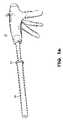
- FIG. 1is a perspective view of a bone fastening device according to the invention.
- FIG. 1 ais a perspective view of a bone fastening device having a protective cannula.
- FIG. 2is a side elevation of a bone arthrodesis implant according to the invention.
- FIG. 3is a side elevation of a fastener.
- FIG. 4is a perspective view.
- FIG. 5is a side elevation of a locking member and washer assembly.
- FIG. 6is a perspective view.
- FIG. 7is a perspective view, partially in phantom.
- FIG. 8is a perspective view of a first, superficial washer.
- FIG. 9is a bottom perspective view.
- FIG. 10is a bottom perspective view of an alternative embodiment.
- FIG. 11is a bottom perspective view, partially broken away.
- FIGS. 12 a - care cross-sectional views, partially broken away, showing alternative orientations.
- FIG. 13is a perspective view of a collet.
- FIG. 14is a schematic side elevation view showing a first mode of operation.
- FIG. 15is a schematic side elevation view showing a second mode of operation.
- FIG. 16is a schematic side elevation, partially broken away and partially in cross-section.
- FIG. 17is a schematic perspective view, partially broken away.
- FIG. 18is a schematic perspective view in a second mode of operation.
- FIG. 19is a schematic perspective view, partially in phantom, in a subsequent mode of operation.
- FIG. 20is a schematic perspective view in yet another mode of operation.
- FIG. 21is a schematic cross-sectional view.
- FIG. 22is a schematic cross-sectional view illustrating a final installation.
- FIG. 23is a schematic perspective view showing bone fixation utilizing an implant according to the invention.
- FIG. 24is a schematic cross section illustrating a bone fixation system and method, in a fist mode of operation.
- FIG. 25is a schematic cross section illustrating a second mode of operation.
- FIG. 26is a schematic cross section illustrating a third mode of operation.
- FIG. 1a bone fastening device 10 according to the invention.
- the device 10has a main body 12 and an elongated housing 14 terminating in a lower end portion 16 .
- the device 10has structure for holding a first washer 20 at a distal portion of the elongated housing 14 and a second washer 24 and locking member 28 in the lower end portion 16 .
- a handle 30is provided to grip the device, and triggers 34 and 38 can be provided to operate the device during the implantation process.
- a guide knob 35can be operated to rotate the housing 14 and attached lower end portion 16 to properly position the second washer 24 .
- a locking lever 32can be provided to lock the device 10 on the bone after the first washer 20 and second washer 24 have been properly positioned. The locking lever 32 may be unlocked to allow repositioning of first washer 20 and second washer 24 .
- a knob 37can be provided to manually advance the fastener and apply appropriate torque.
- a slidable protective cannula or sheath 39may be used to facilitate insertion into the body and cover lower end portion 16 .
- FIG. 1 athere is shown a bone fastening device 10 having a protective cannula or sleeve 39 for shielding the housing 14 and lower end portion 16 during the insertion process.
- a grip 41can be used to pull back the cannula 39 prior to use.
- the housing 14 , lower end portion 16 and guide knob 35can be detachable from the main body 12 .
- Another housing 14 , lower end portion 16 and guide knob 35with another implant, can be attached for reuse of the main body portion 12 .
- the implant 40comprises a fastener having an elongated shaft 44 and a head 48 .
- the fastenerengages the first washer 20 and the second washer 24 and locking member 28 .
- the head 48can have a convex surface 54 for use in engaging the first washer 20 as will be described below.
- Threads 58are provided on the shaft 44 for purposes of engaging the locking member 28 .
- Other engagement structureis possible.
- a pointed end 62is provided for piercing bone during the implantation process.
- Grooves or flutes 66provide space for bone chips to disperse during insertion into locking member 28 and to carry bone debris away from the point 62 as it is progressing through the bone.
- Suitable structuresuch as hex opening 70 is provided for engagement of the fastener 44 to apply compressive and rotational forces during the implantation process. Depressions or other suitable structure can be provided to permit a fastening device to grip the head 48 .
- the second washer 24 and locking member 28are shown in FIGS. 5-7 .
- the second washer 24can have suitable structure such as serrations 80 for engaging the bone surface. Alternative structure is possible.
- the second washer 24is pivotal with respect to the locking member 28 .
- the locking member 28can have suitable structure such as apertures 84 .
- Cooperating engagement structuresuch as clip 88 can be provided for extending through apertures 89 in the second washer 24 and engaging the apertures 84 such that the second washer 24 will engage the locking member 28 .
- a convex surface 92 on the locking member 28can cooperate with a similar concave surface 96 on the second washer 24 .
- the clip 88can be positioned in a suitable retaining groove 90 on the second washer 24 .
- An aperture 104 and slotted L-shaped groove 108can be provided to engage corresponding protrusions on the lower end portion 16 to secure the locking member 28 to the lower end portion 16 of the fastening device 10 .
- the first washer 20is depicted in FIGS. 8-11 .
- the first washer 20can have a concave surface 114 for cooperating with the convex surface 54 of the head 48 of the fastener 44 .
- An elongated opening 118which can be in the form of a tapered slot, permits the pivoting of the first washer 20 relative to the fastener 44 .
- the first washer 20can have structure for allowing the washer to be engaged by the fastening device 10 .
- This structurecan be a circumferential groove 124 which can be engaged by cooperating flange structure on the fastening device 10 . This will allow the first washer 20 to be advanced toward the surface of the bone.
- Additional structuresuch as depressions 130 can be provided for engagement by the fastening device 10 to permit rotation of the first washer 20 . This will assist in properly positioning the first washer 20 .
- the first washer 20can have an angled contact surface 136 which will permit the first washer 20 to cooperate against bone surfaces such as facets which present significant angles. Additional structure can be provided for to promote engagement. This structure can include serrations 140 on the contact surface 136 .
- the opening 118can expand wider in a fluted manner toward the contact surface 136 to permit greater pivoting.
- FIGS. 12 a - cThe manner of engagement between the fastener 44 and the first washer 20 and second washer 24 and locking member 28 is depicted in FIGS. 12 a - c.
- the pivoting motion of the first washer 20is shown.
- This washercan tilt approximately 30° from a transverse section through the screw axis. More or less is possible depending on the bone system that is being fused.
- the second washer 24is capable of tilting +45° to ⁇ 20° from the transverse to the screw axis. More or less is possible.
- Suitable structurecan be provided with the fastening device 10 for engaging the first washer 20 .
- the collethas distal circumferential flanges 144 which engage the groove 124 on the first washer 20 .
- Protrusions 148are provided to engage the depressions 130 to permit the rotation of the first washer 20 .
- Elongated slots 152provide leaf springs 153 for creating a spring action on the lower lips 144 such that the collet 140 can engage and disengage from the first washer 20 using moderate manual force.
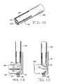
- FIGS. 14-15The manner of engaging the first washer 20 and second washer 24 to the bone is shown in FIGS. 14-15 .
- the locking member 28is engaged to the lower end portion 16 in a suitable slot. Protrusions in the lower end portion 16 can engage the apertures 104 in the locking member 28 .
- the boneis shown schematically as a superior facet 160 and inferior facet 164 .
- the first washer 20is engaged to the collet 140 .
- the lower end portion 16is positioned such that the second washer 24 rests against the inferior facet 164 .
- the pivoting of the lower washer 24 relative to the locking member 28 and lower end 16permits the second washer 24 to match the incline portion 168 of the inferior facet 164 .
- the collet 140is then lowered such that the first washer 20 engages the incline portion 172 of the superior facet 160 .
- the protrusions 148engage the depressions 130 such that rotation of the collet 140 will rotate the first washer 20 to properly position the first washer 20 relative to the incline portion 172 of the superior facet 160 .
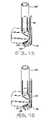
- the installation of the fastener 44is shown in the sequence of FIGS. 16-18 .
- the fastener 44is held by a suitable engagement portion of the device 10 (not shown) and driven toward the superior facet 160 .
- the fastener 44can be engaged such that the head 48 can be rotated and the point 62 can be driven into the facet 160 . Flutes can be provided on the pointed end 62 to remove bone debris as the fastener 44 is rotated and pushed into the bone. In this manner, the fastener 44 will drill through the superior facet 160 and inferior facet 164 . As the fastener 44 is advanced through the bone, it will engage the locking member 28 .
- the threads 58will engage female threads in the locking member 28 .
- the fastener 44will thereby be engaged to the locking member 28 , as shown in FIG. 19 .
- the collet 140can then be removed, as shown in FIGS. 20 and 21 .
- the lower end portion 16is then removed as the fastening device 10 is removed, as shown in FIG. 22 . This results in a completed implant across the superior facet 160 and inferior facet 164 , as shown in FIG. 23 .
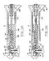
- FIGS. 24-26A bone fixation device 10 as used during an implantation procedure is illustrated in FIGS. 24-26 .
- the device 10has an elongated housing 14 in the general shape of a cannula. Within the housing is the collet 140 .
- the collet 140has structure for engaging the first washer 20 . Any structure is possible, however, the collet 140 in FIG. 24 has inwardly directed circumferential holding flanges 144 .
- the holding flanges 144engage the groove 124 on the first washer 20 .
- the collet 140further can have protrusions 148 which engage the depressions 130 in the first washer 20 .
- the first washer 20is thereby held against movement out of the collet 140 and against rotation relative to the collet 140 .
- the spring force holding the first washer 20 in the collet 140is such that a manual force can be used to remove the collet 140 from the first washer 20 after the first washer 20 has been secured to the bone.
- the collet 140is mounted in the housing 14 so as to be axially movable therethrough.
- the collet 140can have structure for slidably engaging a guide groove 222 or other suitable structure.
- the first trigger 34can be operated to move the collet 140 and first washer 20 through the housing 14 from the position shown in FIG. 24 to the position shown in FIG. 25 .
- gear 230is rotated the shaft 210 is pulled away by the threaded end of the shaft 246 .
- the first washer 20will be seated against the superior facet 160
- the second washer 24will be seated against the inferior facet 164 .
- the guide knob 35can be rotated to properly position the second washer 24 if the orientation is not correct.
- the locking lever 32can be operated to clamp the device to the facet.
- the helical gear 230is then rotated by the action of the trigger 38 , which causes the mostly slidable hexagonal or flat faced shaft 210 to rotate. This rotates the extended threaded end of the shaft 246 , which is engaged to mating internal threads 250 on an interior surface of the collet 140 .
- the face of threaded end 246includes structure for engaging the fastener 44 , such as a hexagonal tip. Rotation of the threaded end 246 will thereby rotate and advance the fastener 44 .
- the fastener 44will advance through the first washer 20 , and through the superior facet 160 and inferior facet 164 due to the drilling action created by the forward and rotational movement of the fastener 44 .
- the fastener 44will then advance through the second washer 24 and into the locking member 28 .
- the threads 58 on the fastener 44will engage cooperating threads on an inside surface of the locking member 28 .
- the knob 37can then be operated to properly torque the implant 40 including to fully seat fastener 44 with locking member 28 .
- the inventionprovides numerous advantages over prior art pedicle screw fixation systems.
- the bone joint segmentssuch as the superior facet 160 and inferior facet 164
- the threads 58are only on the lower end of the shaft 44 such that these threads engage only the locking member 28 and do not apply thread stresses to the interior of the bone.
- conventional torqueing mechanismscan be applied such that a known compressive force is applied to the joint.
- the first washer 20 and second washer 24can be provided with varied angled contact surfaces to variously fit differing bone geometries for joining bone segments other than the facets.
- the amount of tilt in the first washer 20 and second washer 24 relative to the fastener 44can be adjusted depending upon the particular bone geometry that is being fused, owing to the pivotal and polyaxial motion that is permitted.
- the installation of the implant 40is reversible.
- the compression of the implant washers 20 and 24can be removed to allow repositioning prior to fastener 44 insertion. Accordingly, the invention provides great variability and flexibility, in addition to ease, control and consistency of installation.
- the various components of the inventionare constructed with constructions of surgical grade plastics or metal, such as titanium. Different dimensions of the various components of the invention are within the scope of the invention.
Landscapes
- Health & Medical Sciences (AREA)
- Orthopedic Medicine & Surgery (AREA)
- Surgery (AREA)
- Life Sciences & Earth Sciences (AREA)
- Biomedical Technology (AREA)
- Public Health (AREA)
- Neurology (AREA)
- Engineering & Computer Science (AREA)
- Veterinary Medicine (AREA)
- Heart & Thoracic Surgery (AREA)
- Medical Informatics (AREA)
- Molecular Biology (AREA)
- Animal Behavior & Ethology (AREA)
- General Health & Medical Sciences (AREA)
- Nuclear Medicine, Radiotherapy & Molecular Imaging (AREA)
- Dentistry (AREA)
- Oral & Maxillofacial Surgery (AREA)
- Surgical Instruments (AREA)
Abstract
Description
Claims (6)
Priority Applications (12)
| Application Number | Priority Date | Filing Date | Title |
|---|---|---|---|
| US10/973,524US7563275B2 (en) | 2002-10-10 | 2004-10-26 | Bone fixation implant system and method |
| CNB2005800449185ACN100522090C (en) | 2004-10-26 | 2005-10-26 | Bone fixation implant system and method |
| PCT/US2005/038676WO2006047646A2 (en) | 2002-10-10 | 2005-10-26 | Bone fixation implant system and method |
| JP2007539089AJP5113524B2 (en) | 2004-10-26 | 2005-10-26 | Bone fixation implant system and method |
| KR1020077012051AKR101248533B1 (en) | 2004-10-26 | 2005-10-26 | Bone fixation implant system and method |
| AU2005299362AAU2005299362B2 (en) | 2004-10-26 | 2005-10-26 | Bone fixation implant system and method |
| EP05819938AEP1819286A4 (en) | 2004-10-26 | 2005-10-26 | Bone fixation implant system and method |
| MX2007005081AMX2007005081A (en) | 2004-10-26 | 2005-10-26 | Bone fixation implant system and method. |
| IL182823AIL182823A0 (en) | 2004-10-26 | 2007-04-26 | Bone fixation implant system and method |
| ZA200704321AZA200704321B (en) | 2004-10-26 | 2007-05-25 | Bone fixation implant system and method |
| US12/122,498US8002812B2 (en) | 2002-10-10 | 2008-05-16 | Bone fixation implant system and method |
| US13/216,087US8747408B2 (en) | 2002-10-10 | 2011-08-23 | Bone fixation implant system and method |
Applications Claiming Priority (3)
| Application Number | Priority Date | Filing Date | Title |
|---|---|---|---|
| US41754302P | 2002-10-10 | 2002-10-10 | |
| US10/683,076US7608094B2 (en) | 2002-10-10 | 2003-10-10 | Percutaneous facet fixation system |
| US10/973,524US7563275B2 (en) | 2002-10-10 | 2004-10-26 | Bone fixation implant system and method |
Related Parent Applications (1)
| Application Number | Title | Priority Date | Filing Date |
|---|---|---|---|
| US10/683,076Continuation-In-PartUS7608094B2 (en) | 2002-10-10 | 2003-10-10 | Percutaneous facet fixation system |
Related Child Applications (1)
| Application Number | Title | Priority Date | Filing Date |
|---|---|---|---|
| US12/122,498Continuation-In-PartUS8002812B2 (en) | 2002-10-10 | 2008-05-16 | Bone fixation implant system and method |
Publications (2)
| Publication Number | Publication Date |
|---|---|
| US20050234459A1 US20050234459A1 (en) | 2005-10-20 |
| US7563275B2true US7563275B2 (en) | 2009-07-21 |
Family
ID=37075259
Family Applications (1)
| Application Number | Title | Priority Date | Filing Date |
|---|---|---|---|
| US10/973,524Expired - Fee RelatedUS7563275B2 (en) | 2002-10-10 | 2004-10-26 | Bone fixation implant system and method |
Country Status (2)
| Country | Link |
|---|---|
| US (1) | US7563275B2 (en) |
| WO (1) | WO2006047646A2 (en) |
Cited By (51)
| Publication number | Priority date | Publication date | Assignee | Title |
|---|---|---|---|---|
| US20100191293A1 (en)* | 2003-06-18 | 2010-07-29 | Jackson Roger P | Polyaxial bone anchor with spline capture connection and lower pressure insert |
| US20110040338A1 (en)* | 2003-08-28 | 2011-02-17 | Jackson Roger P | Polyaxial bone anchor having an open retainer with conical, cylindrical or curvate capture |
| US20110160772A1 (en)* | 2009-12-28 | 2011-06-30 | Arcenio Gregory B | Systems and methods for performing spinal fusion |
| US20110190825A1 (en)* | 2009-11-09 | 2011-08-04 | Centinel Spine, Inc. | System and method for stabilizing a posterior fusion over motion segments |
| US20110190821A1 (en)* | 2010-02-04 | 2011-08-04 | Spinefrontier, Inc | Spinal screw assembly |
| WO2012006216A1 (en) | 2010-07-08 | 2012-01-12 | X-Spine Systems, Inc. | Spinal stabilization system utilizing screw and external facet and/or lamina fixation |
| WO2012012328A1 (en) | 2010-07-20 | 2012-01-26 | X-Spine Systems, Inc. | Spinal facet compression screw with variable pitch thread zones and buttress head |
| US8137386B2 (en) | 2003-08-28 | 2012-03-20 | Jackson Roger P | Polyaxial bone screw apparatus |
| US8308782B2 (en) | 2004-11-23 | 2012-11-13 | Jackson Roger P | Bone anchors with longitudinal connecting member engaging inserts and closures for fixation and optional angulation |
| US8377067B2 (en) | 2004-02-27 | 2013-02-19 | Roger P. Jackson | Orthopedic implant rod reduction tool set and method |
| US8394133B2 (en) | 2004-02-27 | 2013-03-12 | Roger P. Jackson | Dynamic fixation assemblies with inner core and outer coil-like member |
| US8398682B2 (en) | 2003-06-18 | 2013-03-19 | Roger P. Jackson | Polyaxial bone screw assembly |
| US8444681B2 (en) | 2009-06-15 | 2013-05-21 | Roger P. Jackson | Polyaxial bone anchor with pop-on shank, friction fit retainer and winged insert |
| US8529609B2 (en) | 2009-12-01 | 2013-09-10 | Osteomed Llc | Polyaxial facet fixation screw system |
| WO2013134004A1 (en) | 2012-03-06 | 2013-09-12 | X-Spine Systems, Inc. | Minimally invasive spinal facet compression screw and system for bone joint fusion and fixation |
| US8556938B2 (en) | 2009-06-15 | 2013-10-15 | Roger P. Jackson | Polyaxial bone anchor with non-pivotable retainer and pop-on shank, some with friction fit |
| US20140031830A1 (en)* | 2012-07-24 | 2014-01-30 | Paradigm Spine, Llc | Bone fastener assembly instrument |
| US8652136B2 (en) | 2011-08-15 | 2014-02-18 | Zimmer, Gmbh | Femoral fracture fixation device |
| US8814911B2 (en) | 2003-06-18 | 2014-08-26 | Roger P. Jackson | Polyaxial bone screw with cam connection and lock and release insert |
| US8814913B2 (en) | 2002-09-06 | 2014-08-26 | Roger P Jackson | Helical guide and advancement flange with break-off extensions |
| US8894657B2 (en) | 2004-02-27 | 2014-11-25 | Roger P. Jackson | Tool system for dynamic spinal implants |
| US8911479B2 (en) | 2012-01-10 | 2014-12-16 | Roger P. Jackson | Multi-start closures for open implants |
| US8936623B2 (en) | 2003-06-18 | 2015-01-20 | Roger P. Jackson | Polyaxial bone screw assembly |
| US8998966B2 (en) | 2009-12-01 | 2015-04-07 | Osteomed, Llc | Polyaxial facet fixation screw system with fixation augmentation |
| US8998968B1 (en) | 2012-11-28 | 2015-04-07 | Choice Spine, Lp | Facet screw system |
| US8998959B2 (en) | 2009-06-15 | 2015-04-07 | Roger P Jackson | Polyaxial bone anchors with pop-on shank, fully constrained friction fit retainer and lock and release insert |
| US9050139B2 (en) | 2004-02-27 | 2015-06-09 | Roger P. Jackson | Orthopedic implant rod reduction tool set and method |
| US9078707B2 (en) | 2009-12-01 | 2015-07-14 | Osteomed Llc | Polyaxial facet fixation screw system with cannula inserter |
| US9119678B2 (en) | 2011-11-01 | 2015-09-01 | Synergy Disc Replacement Inc. | Facet fixation systems |
| US9168069B2 (en) | 2009-06-15 | 2015-10-27 | Roger P. Jackson | Polyaxial bone anchor with pop-on shank and winged insert with lower skirt for engaging a friction fit retainer |
| US9216039B2 (en) | 2004-02-27 | 2015-12-22 | Roger P. Jackson | Dynamic spinal stabilization assemblies, tool set and method |
| US9393047B2 (en) | 2009-06-15 | 2016-07-19 | Roger P. Jackson | Polyaxial bone anchor with pop-on shank and friction fit retainer with low profile edge lock |
| US9414865B2 (en) | 2011-11-01 | 2016-08-16 | Synergy Disc Replacement Inc. | Joint and bone fixation |
| US9414863B2 (en) | 2005-02-22 | 2016-08-16 | Roger P. Jackson | Polyaxial bone screw with spherical capture, compression insert and alignment and retention structures |
| US9480517B2 (en) | 2009-06-15 | 2016-11-01 | Roger P. Jackson | Polyaxial bone anchor with pop-on shank, shank, friction fit retainer, winged insert and low profile edge lock |
| US9629669B2 (en) | 2004-11-23 | 2017-04-25 | Roger P. Jackson | Spinal fixation tool set and method |
| US9743957B2 (en) | 2004-11-10 | 2017-08-29 | Roger P. Jackson | Polyaxial bone screw with shank articulation pressure insert and method |
| US9907574B2 (en) | 2008-08-01 | 2018-03-06 | Roger P. Jackson | Polyaxial bone anchors with pop-on shank, friction fit fully restrained retainer, insert and tool receiving features |
| US9980753B2 (en) | 2009-06-15 | 2018-05-29 | Roger P Jackson | pivotal anchor with snap-in-place insert having rotation blocking extensions |
| US10039578B2 (en) | 2003-12-16 | 2018-08-07 | DePuy Synthes Products, Inc. | Methods and devices for minimally invasive spinal fixation element placement |
| US10039577B2 (en) | 2004-11-23 | 2018-08-07 | Roger P Jackson | Bone anchor receiver with horizontal radiused tool attachment structures and parallel planar outer surfaces |
| US20180221064A1 (en)* | 2004-06-10 | 2018-08-09 | Spinal Elements, Inc. | Implant and method for facet immobilization |
| US10194951B2 (en) | 2005-05-10 | 2019-02-05 | Roger P. Jackson | Polyaxial bone anchor with compound articulation and pop-on shank |
| US10299839B2 (en) | 2003-12-16 | 2019-05-28 | Medos International Sárl | Percutaneous access devices and bone anchor assemblies |
| US10357260B2 (en) | 2015-11-02 | 2019-07-23 | First Ray, LLC | Orthopedic fastener, retainer, and guide methods |
| US10363070B2 (en) | 2009-06-15 | 2019-07-30 | Roger P. Jackson | Pivotal bone anchor assemblies with pressure inserts and snap on articulating retainers |
| US10376367B2 (en) | 2015-07-02 | 2019-08-13 | First Ray, LLC | Orthopedic fasteners, instruments and methods |
| US10588679B2 (en)* | 2014-11-01 | 2020-03-17 | Numagenesis, Llc | Compression fixation system |
| US11419642B2 (en) | 2003-12-16 | 2022-08-23 | Medos International Sarl | Percutaneous access devices and bone anchor assemblies |
| US11478289B2 (en) | 2018-05-04 | 2022-10-25 | Numagenesis, Llc | Compression fixation system |
| US12383311B2 (en) | 2010-05-14 | 2025-08-12 | Roger P. Jackson | Pivotal bone anchor assembly and method for use thereof |
Families Citing this family (41)
| Publication number | Priority date | Publication date | Assignee | Title |
|---|---|---|---|---|
| US7833250B2 (en) | 2004-11-10 | 2010-11-16 | Jackson Roger P | Polyaxial bone screw with helically wound capture connection |
| US8876868B2 (en) | 2002-09-06 | 2014-11-04 | Roger P. Jackson | Helical guide and advancement flange with radially loaded lip |
| US7377923B2 (en) | 2003-05-22 | 2008-05-27 | Alphatec Spine, Inc. | Variable angle spinal screw assembly |
| US8366753B2 (en) | 2003-06-18 | 2013-02-05 | Jackson Roger P | Polyaxial bone screw assembly with fixed retaining structure |
| US7967850B2 (en) | 2003-06-18 | 2011-06-28 | Jackson Roger P | Polyaxial bone anchor with helical capture connection, insert and dual locking assembly |
| US11241261B2 (en) | 2005-09-30 | 2022-02-08 | Roger P Jackson | Apparatus and method for soft spinal stabilization using a tensionable cord and releasable end structure |
| US7651502B2 (en) | 2004-09-24 | 2010-01-26 | Jackson Roger P | Spinal fixation tool set and method for rod reduction and fastener insertion |
| US9271766B2 (en) | 2004-10-26 | 2016-03-01 | P Tech, Llc | Devices and methods for stabilizing tissue and implants |
| US9463012B2 (en)* | 2004-10-26 | 2016-10-11 | P Tech, Llc | Apparatus for guiding and positioning an implant |
| US9173647B2 (en) | 2004-10-26 | 2015-11-03 | P Tech, Llc | Tissue fixation system |
| US8926672B2 (en) | 2004-11-10 | 2015-01-06 | Roger P. Jackson | Splay control closure for open bone anchor |
| WO2006057837A1 (en) | 2004-11-23 | 2006-06-01 | Jackson Roger P | Spinal fixation tool attachment structure |
| US8702755B2 (en)* | 2006-08-11 | 2014-04-22 | Gmedelaware 2 Llc | Angled washer polyaxial connection for dynamic spine prosthesis |
| US8231660B2 (en)* | 2007-07-18 | 2012-07-31 | Spinefrontier Inc | System and method for facet fixation |
| US8894685B2 (en) | 2007-04-13 | 2014-11-25 | DePuy Synthes Products, LLC | Facet fixation and fusion screw and washer assembly and method of use |
| US8197513B2 (en) | 2007-04-13 | 2012-06-12 | Depuy Spine, Inc. | Facet fixation and fusion wedge and method of use |
| US20090187219A1 (en)* | 2007-08-03 | 2009-07-23 | Neal Pachtman | Spinal Facet Joint Immobilization Systems and Methods |
| US8940019B2 (en) | 2007-12-28 | 2015-01-27 | Osteomed Spine, Inc. | Bone tissue fixation device and method |
| US20090216273A1 (en)* | 2008-02-19 | 2009-08-27 | U. S. Spinal Technologies, L.L.C. | Curved facet joint fixation assembly and associated implantation tool and method |
| US20100076490A1 (en)* | 2008-02-28 | 2010-03-25 | Jonathan Greenwald | Facet joint broaching instrument, implant, and associated method |
| US20090234394A1 (en)* | 2008-03-11 | 2009-09-17 | David Crook | Unilateral facet bolt inserter |
| US20090275993A1 (en)* | 2008-04-30 | 2009-11-05 | Phan Christopher U | Apparatus and methods for inserting facet screws |
| US20100087859A1 (en)* | 2008-10-03 | 2010-04-08 | Jackson Jr Darrell | Facet button assembly and related surgical methods |
| US11229457B2 (en) | 2009-06-15 | 2022-01-25 | Roger P. Jackson | Pivotal bone anchor assembly with insert tool deployment |
| US8721686B2 (en)* | 2009-06-23 | 2014-05-13 | Osteomed Llc | Spinous process fusion implants and insertion, compression, and locking instrumentation |
| US8636772B2 (en) | 2009-06-23 | 2014-01-28 | Osteomed Llc | Bone plates, screws, and instruments |
| EP2445428A2 (en) | 2009-06-23 | 2012-05-02 | Osteomed Spine, Inc. | Bone tissue clamp |
| BR112012003050A2 (en)* | 2009-08-10 | 2019-09-24 | Osteomed Llc | bone plate assembly, bone surface attachment plate, cushion and bone plate |
| US9089372B2 (en) | 2010-07-12 | 2015-07-28 | DePuy Synthes Products, Inc. | Pedicular facet fusion screw with plate |
| US8911478B2 (en) | 2012-11-21 | 2014-12-16 | Roger P. Jackson | Splay control closure for open bone anchor |
| US10058354B2 (en) | 2013-01-28 | 2018-08-28 | Roger P. Jackson | Pivotal bone anchor assembly with frictional shank head seating surfaces |
| US8852239B2 (en) | 2013-02-15 | 2014-10-07 | Roger P Jackson | Sagittal angle screw with integral shank and receiver |
| US9566092B2 (en) | 2013-10-29 | 2017-02-14 | Roger P. Jackson | Cervical bone anchor with collet retainer and outer locking sleeve |
| US9717533B2 (en) | 2013-12-12 | 2017-08-01 | Roger P. Jackson | Bone anchor closure pivot-splay control flange form guide and advancement structure |
| US9451993B2 (en) | 2014-01-09 | 2016-09-27 | Roger P. Jackson | Bi-radial pop-on cervical bone anchor |
| CA2949060A1 (en)* | 2014-05-12 | 2015-11-19 | DePuy Synthes Products, Inc. | Sacral fixation system |
| US10064670B2 (en)* | 2014-05-12 | 2018-09-04 | DePuy Synthes Products, Inc. | Sacral fixation system |
| US10064658B2 (en) | 2014-06-04 | 2018-09-04 | Roger P. Jackson | Polyaxial bone anchor with insert guides |
| US9597119B2 (en) | 2014-06-04 | 2017-03-21 | Roger P. Jackson | Polyaxial bone anchor with polymer sleeve |
| FR3048176A1 (en) | 2016-02-26 | 2017-09-01 | Ldr Medical | SPINAL ARTHRODESIS IMPLANT SYSTEM |
| EP4338694A1 (en)* | 2022-09-14 | 2024-03-20 | Smith & Nephew, Inc. | Collinear reduction clamp |
Citations (31)
| Publication number | Priority date | Publication date | Assignee | Title |
|---|---|---|---|---|
| US3178971A (en)* | 1963-09-27 | 1965-04-20 | Chicago Specialty Mfg Co | Socket wrench |
| US3545444A (en)* | 1967-10-02 | 1970-12-08 | United States Surgical Corp | Wire suture wrapping instrument |
| US3822818A (en)* | 1973-02-20 | 1974-07-09 | A Strekopytov | Surgical instrument for joining osseous tissues by staples |
| US5234431A (en)* | 1991-04-03 | 1993-08-10 | Waldemar Link Gmbh & Co. | Bone plate arrangement |
| US5527312A (en) | 1994-08-19 | 1996-06-18 | Salut, Ltd. | Facet screw anchor |
| US5558674A (en) | 1993-12-17 | 1996-09-24 | Smith & Nephew Richards, Inc. | Devices and methods for posterior spinal fixation |
| US5649931A (en)* | 1996-01-16 | 1997-07-22 | Zimmer, Inc. | Orthopaedic apparatus for driving and/or removing a bone screw |
| US5690632A (en)* | 1995-11-30 | 1997-11-25 | Schwartz; Paul Steven | Osteosynthesis screw fastener having angularly adjustable threads and methods of use therefor |
| US5720751A (en)* | 1996-11-27 | 1998-02-24 | Jackson; Roger P. | Tools for use in seating spinal rods in open ended implants |
| US5735850A (en)* | 1995-02-17 | 1998-04-07 | Sulzer Medizinaltechnik Ag | Fastening system for pedicel screws |
| US6050997A (en)* | 1999-01-25 | 2000-04-18 | Mullane; Thomas S. | Spinal fixation system |
| US6146383A (en)* | 1998-02-02 | 2000-11-14 | Sulzer Orthopadie Ag | Pivotal securing system at a bone screw |
| US6368319B1 (en)* | 1999-05-06 | 2002-04-09 | Bernd Schaefer | Pedicle screw |
| US6485518B1 (en) | 1999-12-10 | 2002-11-26 | Nuvasive | Facet screw and bone allograft intervertebral support and fusion system |
| US6540747B1 (en) | 1999-04-16 | 2003-04-01 | Nuvasive, Inc. | System for securing joints together |
| US6623485B2 (en)* | 2001-10-17 | 2003-09-23 | Hammill Manufacturing Company | Split ring bone screw for a spinal fixation system |
| US6648893B2 (en) | 2000-10-27 | 2003-11-18 | Blackstone Medical, Inc. | Facet fixation devices |
| US6669698B1 (en) | 2000-10-24 | 2003-12-30 | Sdgi Holdings, Inc. | Vertebrae fastener placement guide |
| US20040111093A1 (en) | 2002-12-02 | 2004-06-10 | Chappuis James L. | Facet fusion system |
| US6811567B2 (en) | 1999-10-22 | 2004-11-02 | Archus Orthopedics Inc. | Facet arthroplasty devices and methods |
| US20040225360A1 (en) | 2000-12-14 | 2004-11-11 | Malone David G. | Devices and methods for facilitating controlled bone growth or repair |
| US20040254575A1 (en) | 2003-06-13 | 2004-12-16 | Obenchain Theodore G. | Method and apparatus for stabilization of facet joint |
| US20050124993A1 (en) | 2002-12-02 | 2005-06-09 | Chappuis James L. | Facet fusion system |
| US20050149030A1 (en) | 2003-12-19 | 2005-07-07 | Depuy Spine, Inc. | Facet joint fixation system |
| US6949123B2 (en) | 1999-10-22 | 2005-09-27 | Archus Orthopedics Inc. | Facet arthroplasty devices and methods |
| US6966930B2 (en) | 2003-10-20 | 2005-11-22 | Impliant Ltd. | Facet prosthesis |
| US20050273110A1 (en) | 2004-05-12 | 2005-12-08 | Boehm Frank H Jr | Devices for performing fusion surgery using a split thickness technique to provide vascularized autograft |
| US20060004367A1 (en) | 2004-06-17 | 2006-01-05 | Alamin Todd F | Facet joint fusion devices and methods |
| US7041136B2 (en) | 2000-11-29 | 2006-05-09 | Facet Solutions, Inc. | Facet joint replacement |
| US20060111779A1 (en) | 2004-11-22 | 2006-05-25 | Orthopedic Development Corporation, A Florida Corporation | Minimally invasive facet joint fusion |
| US20060111780A1 (en) | 2004-11-22 | 2006-05-25 | Orthopedic Development Corporation | Minimally invasive facet joint hemi-arthroplasty |
Family Cites Families (3)
| Publication number | Priority date | Publication date | Assignee | Title |
|---|---|---|---|---|
| US5613968A (en)* | 1995-05-01 | 1997-03-25 | Lin; Chih-I | Universal pad fixation device for orthopedic surgery |
| US5931844A (en)* | 1998-03-31 | 1999-08-03 | Smith & Nephew, Inc. | Surgical drive tool |
| US6692689B2 (en)* | 2001-12-14 | 2004-02-17 | Jorge A. Morando | Sink roll assembly with forced hydrodynamic film lubricated bearings and self-aligning holding arms |
- 2004
- 2004-10-26USUS10/973,524patent/US7563275B2/ennot_activeExpired - Fee Related
- 2005
- 2005-10-26WOPCT/US2005/038676patent/WO2006047646A2/enactiveApplication Filing
Patent Citations (31)
| Publication number | Priority date | Publication date | Assignee | Title |
|---|---|---|---|---|
| US3178971A (en)* | 1963-09-27 | 1965-04-20 | Chicago Specialty Mfg Co | Socket wrench |
| US3545444A (en)* | 1967-10-02 | 1970-12-08 | United States Surgical Corp | Wire suture wrapping instrument |
| US3822818A (en)* | 1973-02-20 | 1974-07-09 | A Strekopytov | Surgical instrument for joining osseous tissues by staples |
| US5234431A (en)* | 1991-04-03 | 1993-08-10 | Waldemar Link Gmbh & Co. | Bone plate arrangement |
| US5558674A (en) | 1993-12-17 | 1996-09-24 | Smith & Nephew Richards, Inc. | Devices and methods for posterior spinal fixation |
| US5527312A (en) | 1994-08-19 | 1996-06-18 | Salut, Ltd. | Facet screw anchor |
| US5735850A (en)* | 1995-02-17 | 1998-04-07 | Sulzer Medizinaltechnik Ag | Fastening system for pedicel screws |
| US5690632A (en)* | 1995-11-30 | 1997-11-25 | Schwartz; Paul Steven | Osteosynthesis screw fastener having angularly adjustable threads and methods of use therefor |
| US5649931A (en)* | 1996-01-16 | 1997-07-22 | Zimmer, Inc. | Orthopaedic apparatus for driving and/or removing a bone screw |
| US5720751A (en)* | 1996-11-27 | 1998-02-24 | Jackson; Roger P. | Tools for use in seating spinal rods in open ended implants |
| US6146383A (en)* | 1998-02-02 | 2000-11-14 | Sulzer Orthopadie Ag | Pivotal securing system at a bone screw |
| US6050997A (en)* | 1999-01-25 | 2000-04-18 | Mullane; Thomas S. | Spinal fixation system |
| US6540747B1 (en) | 1999-04-16 | 2003-04-01 | Nuvasive, Inc. | System for securing joints together |
| US6368319B1 (en)* | 1999-05-06 | 2002-04-09 | Bernd Schaefer | Pedicle screw |
| US6949123B2 (en) | 1999-10-22 | 2005-09-27 | Archus Orthopedics Inc. | Facet arthroplasty devices and methods |
| US6811567B2 (en) | 1999-10-22 | 2004-11-02 | Archus Orthopedics Inc. | Facet arthroplasty devices and methods |
| US6485518B1 (en) | 1999-12-10 | 2002-11-26 | Nuvasive | Facet screw and bone allograft intervertebral support and fusion system |
| US6669698B1 (en) | 2000-10-24 | 2003-12-30 | Sdgi Holdings, Inc. | Vertebrae fastener placement guide |
| US6648893B2 (en) | 2000-10-27 | 2003-11-18 | Blackstone Medical, Inc. | Facet fixation devices |
| US7041136B2 (en) | 2000-11-29 | 2006-05-09 | Facet Solutions, Inc. | Facet joint replacement |
| US20040225360A1 (en) | 2000-12-14 | 2004-11-11 | Malone David G. | Devices and methods for facilitating controlled bone growth or repair |
| US6623485B2 (en)* | 2001-10-17 | 2003-09-23 | Hammill Manufacturing Company | Split ring bone screw for a spinal fixation system |
| US20040111093A1 (en) | 2002-12-02 | 2004-06-10 | Chappuis James L. | Facet fusion system |
| US20050124993A1 (en) | 2002-12-02 | 2005-06-09 | Chappuis James L. | Facet fusion system |
| US20040254575A1 (en) | 2003-06-13 | 2004-12-16 | Obenchain Theodore G. | Method and apparatus for stabilization of facet joint |
| US6966930B2 (en) | 2003-10-20 | 2005-11-22 | Impliant Ltd. | Facet prosthesis |
| US20050149030A1 (en) | 2003-12-19 | 2005-07-07 | Depuy Spine, Inc. | Facet joint fixation system |
| US20050273110A1 (en) | 2004-05-12 | 2005-12-08 | Boehm Frank H Jr | Devices for performing fusion surgery using a split thickness technique to provide vascularized autograft |
| US20060004367A1 (en) | 2004-06-17 | 2006-01-05 | Alamin Todd F | Facet joint fusion devices and methods |
| US20060111779A1 (en) | 2004-11-22 | 2006-05-25 | Orthopedic Development Corporation, A Florida Corporation | Minimally invasive facet joint fusion |
| US20060111780A1 (en) | 2004-11-22 | 2006-05-25 | Orthopedic Development Corporation | Minimally invasive facet joint hemi-arthroplasty |
Cited By (71)
| Publication number | Priority date | Publication date | Assignee | Title |
|---|---|---|---|---|
| US8814913B2 (en) | 2002-09-06 | 2014-08-26 | Roger P Jackson | Helical guide and advancement flange with break-off extensions |
| US8398682B2 (en) | 2003-06-18 | 2013-03-19 | Roger P. Jackson | Polyaxial bone screw assembly |
| US20100191293A1 (en)* | 2003-06-18 | 2010-07-29 | Jackson Roger P | Polyaxial bone anchor with spline capture connection and lower pressure insert |
| US8936623B2 (en) | 2003-06-18 | 2015-01-20 | Roger P. Jackson | Polyaxial bone screw assembly |
| US8814911B2 (en) | 2003-06-18 | 2014-08-26 | Roger P. Jackson | Polyaxial bone screw with cam connection and lock and release insert |
| US8377102B2 (en) | 2003-06-18 | 2013-02-19 | Roger P. Jackson | Polyaxial bone anchor with spline capture connection and lower pressure insert |
| US20110040338A1 (en)* | 2003-08-28 | 2011-02-17 | Jackson Roger P | Polyaxial bone anchor having an open retainer with conical, cylindrical or curvate capture |
| US8137386B2 (en) | 2003-08-28 | 2012-03-20 | Jackson Roger P | Polyaxial bone screw apparatus |
| US11426216B2 (en) | 2003-12-16 | 2022-08-30 | DePuy Synthes Products, Inc. | Methods and devices for minimally invasive spinal fixation element placement |
| US11419642B2 (en) | 2003-12-16 | 2022-08-23 | Medos International Sarl | Percutaneous access devices and bone anchor assemblies |
| US10039578B2 (en) | 2003-12-16 | 2018-08-07 | DePuy Synthes Products, Inc. | Methods and devices for minimally invasive spinal fixation element placement |
| US10299839B2 (en) | 2003-12-16 | 2019-05-28 | Medos International Sárl | Percutaneous access devices and bone anchor assemblies |
| US8394133B2 (en) | 2004-02-27 | 2013-03-12 | Roger P. Jackson | Dynamic fixation assemblies with inner core and outer coil-like member |
| US8377067B2 (en) | 2004-02-27 | 2013-02-19 | Roger P. Jackson | Orthopedic implant rod reduction tool set and method |
| US9216039B2 (en) | 2004-02-27 | 2015-12-22 | Roger P. Jackson | Dynamic spinal stabilization assemblies, tool set and method |
| US9055978B2 (en) | 2004-02-27 | 2015-06-16 | Roger P. Jackson | Orthopedic implant rod reduction tool set and method |
| US9050139B2 (en) | 2004-02-27 | 2015-06-09 | Roger P. Jackson | Orthopedic implant rod reduction tool set and method |
| US9918751B2 (en) | 2004-02-27 | 2018-03-20 | Roger P. Jackson | Tool system for dynamic spinal implants |
| US8894657B2 (en) | 2004-02-27 | 2014-11-25 | Roger P. Jackson | Tool system for dynamic spinal implants |
| US20180221064A1 (en)* | 2004-06-10 | 2018-08-09 | Spinal Elements, Inc. | Implant and method for facet immobilization |
| US9743957B2 (en) | 2004-11-10 | 2017-08-29 | Roger P. Jackson | Polyaxial bone screw with shank articulation pressure insert and method |
| US8308782B2 (en) | 2004-11-23 | 2012-11-13 | Jackson Roger P | Bone anchors with longitudinal connecting member engaging inserts and closures for fixation and optional angulation |
| US8840652B2 (en) | 2004-11-23 | 2014-09-23 | Roger P. Jackson | Bone anchors with longitudinal connecting member engaging inserts and closures for fixation and optional angulation |
| US10039577B2 (en) | 2004-11-23 | 2018-08-07 | Roger P Jackson | Bone anchor receiver with horizontal radiused tool attachment structures and parallel planar outer surfaces |
| US11389214B2 (en) | 2004-11-23 | 2022-07-19 | Roger P. Jackson | Spinal fixation tool set and method |
| US9629669B2 (en) | 2004-11-23 | 2017-04-25 | Roger P. Jackson | Spinal fixation tool set and method |
| USRE47551E1 (en) | 2005-02-22 | 2019-08-06 | Roger P. Jackson | Polyaxial bone screw with spherical capture, compression insert and alignment and retention structures |
| US9414863B2 (en) | 2005-02-22 | 2016-08-16 | Roger P. Jackson | Polyaxial bone screw with spherical capture, compression insert and alignment and retention structures |
| US10194951B2 (en) | 2005-05-10 | 2019-02-05 | Roger P. Jackson | Polyaxial bone anchor with compound articulation and pop-on shank |
| US10792074B2 (en) | 2007-01-22 | 2020-10-06 | Roger P. Jackson | Pivotal bone anchor assemly with twist-in-place friction fit insert |
| US9907574B2 (en) | 2008-08-01 | 2018-03-06 | Roger P. Jackson | Polyaxial bone anchors with pop-on shank, friction fit fully restrained retainer, insert and tool receiving features |
| US8556938B2 (en) | 2009-06-15 | 2013-10-15 | Roger P. Jackson | Polyaxial bone anchor with non-pivotable retainer and pop-on shank, some with friction fit |
| US10363070B2 (en) | 2009-06-15 | 2019-07-30 | Roger P. Jackson | Pivotal bone anchor assemblies with pressure inserts and snap on articulating retainers |
| US9393047B2 (en) | 2009-06-15 | 2016-07-19 | Roger P. Jackson | Polyaxial bone anchor with pop-on shank and friction fit retainer with low profile edge lock |
| US8998959B2 (en) | 2009-06-15 | 2015-04-07 | Roger P Jackson | Polyaxial bone anchors with pop-on shank, fully constrained friction fit retainer and lock and release insert |
| US9480517B2 (en) | 2009-06-15 | 2016-11-01 | Roger P. Jackson | Polyaxial bone anchor with pop-on shank, shank, friction fit retainer, winged insert and low profile edge lock |
| US9168069B2 (en) | 2009-06-15 | 2015-10-27 | Roger P. Jackson | Polyaxial bone anchor with pop-on shank and winged insert with lower skirt for engaging a friction fit retainer |
| US8444681B2 (en) | 2009-06-15 | 2013-05-21 | Roger P. Jackson | Polyaxial bone anchor with pop-on shank, friction fit retainer and winged insert |
| US9918745B2 (en) | 2009-06-15 | 2018-03-20 | Roger P. Jackson | Polyaxial bone anchor with pop-on shank and winged insert with friction fit compressive collet |
| US9504496B2 (en) | 2009-06-15 | 2016-11-29 | Roger P. Jackson | Polyaxial bone anchor with pop-on shank, friction fit retainer and winged insert |
| US9980753B2 (en) | 2009-06-15 | 2018-05-29 | Roger P Jackson | pivotal anchor with snap-in-place insert having rotation blocking extensions |
| US20110190825A1 (en)* | 2009-11-09 | 2011-08-04 | Centinel Spine, Inc. | System and method for stabilizing a posterior fusion over motion segments |
| US9592081B2 (en)* | 2009-11-09 | 2017-03-14 | Centinel Spine, Inc. | System and method for stabilizing a posterior fusion over motion segments |
| US20160008039A1 (en)* | 2009-11-09 | 2016-01-14 | Centinel Spine, Inc. | System and method for stabilizing a posterior fusion over motion segments |
| US9078701B2 (en)* | 2009-11-09 | 2015-07-14 | Centinel Spine, Inc. | System and method for stabilizing a posterior fusion over motion segments |
| US9078707B2 (en) | 2009-12-01 | 2015-07-14 | Osteomed Llc | Polyaxial facet fixation screw system with cannula inserter |
| US8529609B2 (en) | 2009-12-01 | 2013-09-10 | Osteomed Llc | Polyaxial facet fixation screw system |
| US8998966B2 (en) | 2009-12-01 | 2015-04-07 | Osteomed, Llc | Polyaxial facet fixation screw system with fixation augmentation |
| US20110160772A1 (en)* | 2009-12-28 | 2011-06-30 | Arcenio Gregory B | Systems and methods for performing spinal fusion |
| US8690924B2 (en) | 2010-02-04 | 2014-04-08 | Spinefrontier Inc | Spinal screw assembly |
| US20110190821A1 (en)* | 2010-02-04 | 2011-08-04 | Spinefrontier, Inc | Spinal screw assembly |
| US12383311B2 (en) | 2010-05-14 | 2025-08-12 | Roger P. Jackson | Pivotal bone anchor assembly and method for use thereof |
| WO2012006216A1 (en) | 2010-07-08 | 2012-01-12 | X-Spine Systems, Inc. | Spinal stabilization system utilizing screw and external facet and/or lamina fixation |
| EP2992845A1 (en) | 2010-07-08 | 2016-03-09 | X-spine Systems, Inc. | Spinal stabilization system utilizing screw and external facet and/or lamina fixation |
| WO2012012328A1 (en) | 2010-07-20 | 2012-01-26 | X-Spine Systems, Inc. | Spinal facet compression screw with variable pitch thread zones and buttress head |
| US8992587B2 (en) | 2010-07-20 | 2015-03-31 | X-Spine Systems, Inc. | Spinal facet compression screw with variable pitch thread zones and buttress head |
| US8945193B2 (en) | 2010-07-20 | 2015-02-03 | X-Spine Systems, Inc. | Minimally invasive spinal facet compression screw and system for bone joint fusion and fixation |
| US9265540B2 (en) | 2010-07-20 | 2016-02-23 | X-Spine Systems, Inc. | Minimally invasive spinal facet compression screw and system for bone joint fusion and fixation |
| US8652136B2 (en) | 2011-08-15 | 2014-02-18 | Zimmer, Gmbh | Femoral fracture fixation device |
| US9119678B2 (en) | 2011-11-01 | 2015-09-01 | Synergy Disc Replacement Inc. | Facet fixation systems |
| US9414865B2 (en) | 2011-11-01 | 2016-08-16 | Synergy Disc Replacement Inc. | Joint and bone fixation |
| US8911479B2 (en) | 2012-01-10 | 2014-12-16 | Roger P. Jackson | Multi-start closures for open implants |
| WO2013134004A1 (en) | 2012-03-06 | 2013-09-12 | X-Spine Systems, Inc. | Minimally invasive spinal facet compression screw and system for bone joint fusion and fixation |
| US20140031830A1 (en)* | 2012-07-24 | 2014-01-30 | Paradigm Spine, Llc | Bone fastener assembly instrument |
| US9173695B2 (en)* | 2012-07-24 | 2015-11-03 | Paradigm Spine, Llc | Bone fastener assembly instrument |
| US8998968B1 (en) | 2012-11-28 | 2015-04-07 | Choice Spine, Lp | Facet screw system |
| US10588679B2 (en)* | 2014-11-01 | 2020-03-17 | Numagenesis, Llc | Compression fixation system |
| US10376367B2 (en) | 2015-07-02 | 2019-08-13 | First Ray, LLC | Orthopedic fasteners, instruments and methods |
| US10702290B2 (en) | 2015-11-02 | 2020-07-07 | First Ray, LLC | Orthopedic fastener, retainer, and guide |
| US10357260B2 (en) | 2015-11-02 | 2019-07-23 | First Ray, LLC | Orthopedic fastener, retainer, and guide methods |
| US11478289B2 (en) | 2018-05-04 | 2022-10-25 | Numagenesis, Llc | Compression fixation system |
Also Published As
| Publication number | Publication date |
|---|---|
| WO2006047646A2 (en) | 2006-05-04 |
| WO2006047646A3 (en) | 2007-02-01 |
| US20050234459A1 (en) | 2005-10-20 |
Similar Documents
| Publication | Publication Date | Title |
|---|---|---|
| US7563275B2 (en) | Bone fixation implant system and method | |
| US20090216273A1 (en) | Curved facet joint fixation assembly and associated implantation tool and method | |
| US10548641B2 (en) | Medical implant receivers having dual lead in closure mating thread forms | |
| US10517646B2 (en) | Stabilizing bone using spinal fixation devices and systems | |
| US8747408B2 (en) | Bone fixation implant system and method | |
| US6858030B2 (en) | Pedicle screw assembly and methods therefor | |
| US8262662B2 (en) | Break-off screw extensions | |
| US7226453B2 (en) | Instrument for inserting, adjusting and removing pedicle screws and other orthopedic implants | |
| US7842071B2 (en) | Transverse connector | |
| EP1850798B1 (en) | Polyaxial bone screw assembly | |
| US20040267275A1 (en) | Spinal implant holder and rod reduction systems and methods | |
| US20110034925A1 (en) | Lagwire system and method for the fixation of bone fractures | |
| US20100312292A1 (en) | Lagwire system and method for the fixation of bone fractures | |
| AU2005299362B2 (en) | Bone fixation implant system and method | |
| US20090234394A1 (en) | Unilateral facet bolt inserter |
Legal Events
| Date | Code | Title | Description |
|---|---|---|---|
| AS | Assignment | Owner name:U.S. SPINAL TECHNOLOGIES, LLC, FLORIDA Free format text:ASSIGNMENT OF ASSIGNORS INTEREST;ASSIGNORS:DOMINGUEZ, LEONEL;PEPPER, JOHN H.;MCDERMOTT, IAN;AND OTHERS;REEL/FRAME:015882/0838;SIGNING DATES FROM 20050201 TO 20050318 Owner name:U.S. SPINAL TECHNOLOGIES, LLC, FLORIDA Free format text:ASSIGNMENT OF ASSIGNORS INTEREST;ASSIGNOR:FALAHEE, MARK H.;REEL/FRAME:015882/0833 Effective date:20050407 | |
| STCF | Information on status: patent grant | Free format text:PATENTED CASE | |
| AS | Assignment | Owner name:US SPINE, INC., UTAH Free format text:CHANGE OF NAME;ASSIGNOR:U.S. SPINAL TECHNOLOGIES, LLC;REEL/FRAME:025420/0972 Effective date:20101123 | |
| AS | Assignment | Owner name:ZIONS FIRST NATIONAL BANK, UTAH Free format text:SECURITY AGREEMENT;ASSIGNOR:US SPINE, INC.;REEL/FRAME:025434/0317 Effective date:20100917 | |
| AS | Assignment | Owner name:KARL KIPKE, AS COLLATERAL AGENT, TEXAS Free format text:SECURITY AGREEMENT;ASSIGNOR:AMEDICA CORPORATION;REEL/FRAME:025900/0168 Effective date:20110303 | |
| FEPP | Fee payment procedure | Free format text:PAYOR NUMBER ASSIGNED (ORIGINAL EVENT CODE: ASPN); ENTITY STATUS OF PATENT OWNER: SMALL ENTITY | |
| AS | Assignment | Owner name:AMEDICA CORPORATION, UTAH Free format text:RELEASE BY SECURED PARTY;ASSIGNOR:AS COLLATERAL AGENT, KARL KIPKE;REEL/FRAME:029492/0321 Effective date:20121214 Owner name:US SPINE, INC., UTAH Free format text:RELEASE BY SECURED PARTY;ASSIGNOR:ZIONS FIRST NATIONAL BANK;REEL/FRAME:029491/0085 Effective date:20121217 Owner name:GE CAPITAL EQUITY INVESTMENTS, INC. C/O GE HEALTHC Free format text:SECURITY AGREEMENT;ASSIGNORS:AMEDICA CORPORATION;US SPINE, INC.;REEL/FRAME:029495/0211 Effective date:20121214 | |
| FPAY | Fee payment | Year of fee payment:4 | |
| AS | Assignment | Owner name:GENERAL ELECTRIC CAPITAL CORPORATION, MARYLAND Free format text:CORRECTIVE ASSIGNMENT TO CORRECT THE NAME OF THE ASSIGNEE PREVIOUSLY RECORDED ON REEL 029495 FRAME 0211. ASSIGNOR(S) HEREBY CONFIRMS THE ASSIGNOR: AMEDICA CORPORATION ASSIGNOR: US SPINE, INC. ASSIGNEE: GENERAL ELECTRIC CAPITAL CORPORATION;ASSIGNORS:AMEDICA CORPORATION;US SPINE, INC.;REEL/FRAME:031581/0831 Effective date:20121214 | |
| FPAY | Fee payment | Year of fee payment:8 | |
| AS | Assignment | Owner name:AMEDICA CORPORATION, UTAH Free format text:ASSIGNMENT OF ASSIGNORS INTEREST;ASSIGNOR:U.S. SPINE, INC.;REEL/FRAME:044795/0780 Effective date:20180127 | |
| AS | Assignment | Owner name:US SPINE, INC., UTAH Free format text:RELEASE BY SECURED PARTY;ASSIGNOR:GENERAL ELECTRIC CAPITAL CORPORATION;REEL/FRAME:047199/0313 Effective date:20140630 Owner name:AMEDICA CORPORATION, UTAH Free format text:RELEASE BY SECURED PARTY;ASSIGNOR:GENERAL ELECTRIC CAPITAL CORPORATION;REEL/FRAME:047199/0313 Effective date:20140630 | |
| AS | Assignment | Owner name:US SPINE, INC., UTAH Free format text:CORRECTIVE ASSIGNMENT TO CORRECT THE PATENT NUMBER PREVIOUSLY RECORDED AT REEL: 047199 FRAME: 0313. ASSIGNOR(S) HEREBY CONFIRMS THE RELEASE OF SECURITY INTEREST;ASSIGNOR:GENERAL ELECTRIC CAPITAL CORPORATION;REEL/FRAME:047403/0953 Effective date:20140630 Owner name:AMEDICA CORPORATION, UTAH Free format text:CORRECTIVE ASSIGNMENT TO CORRECT THE PATENT NUMBER PREVIOUSLY RECORDED AT REEL: 047199 FRAME: 0313. ASSIGNOR(S) HEREBY CONFIRMS THE RELEASE OF SECURITY INTEREST;ASSIGNOR:GENERAL ELECTRIC CAPITAL CORPORATION;REEL/FRAME:047403/0953 Effective date:20140630 | |
| AS | Assignment | Owner name:CTL MEDICAL CORPORATION, TEXAS Free format text:ASSIGNMENT OF ASSIGNORS INTEREST;ASSIGNORS:AMEDICA CORPORATION;U.S. SPINE, INC.;REEL/FRAME:051368/0261 Effective date:20181001 | |
| FEPP | Fee payment procedure | Free format text:MAINTENANCE FEE REMINDER MAILED (ORIGINAL EVENT CODE: REM.); ENTITY STATUS OF PATENT OWNER: SMALL ENTITY | |
| AS | Assignment | Owner name:SOURCE CAPITAL CREDIT OPPORTUNITIES FUND III, LP, GEORGIA Free format text:SECURITY INTEREST;ASSIGNOR:CTL MEDICAL CORPORATION;REEL/FRAME:056417/0606 Effective date:20210513 | |
| AS | Assignment | Owner name:STERLING NATIONAL BANK, NEW YORK Free format text:SECURITY AGREEMENT;ASSIGNOR:CTL MEDICAL CORPORATION;REEL/FRAME:056595/0562 Effective date:20210513 | |
| LAPS | Lapse for failure to pay maintenance fees | Free format text:PATENT EXPIRED FOR FAILURE TO PAY MAINTENANCE FEES (ORIGINAL EVENT CODE: EXP.); ENTITY STATUS OF PATENT OWNER: SMALL ENTITY | |
| STCH | Information on status: patent discontinuation | Free format text:PATENT EXPIRED DUE TO NONPAYMENT OF MAINTENANCE FEES UNDER 37 CFR 1.362 | |
| FP | Lapsed due to failure to pay maintenance fee | Effective date:20210721 |