US7563222B2 - Methods and apparatus for intraocular brachytherapy - Google Patents
Methods and apparatus for intraocular brachytherapyDownload PDFInfo
- Publication number
- US7563222B2 US7563222B2US11/228,030US22803005AUS7563222B2US 7563222 B2US7563222 B2US 7563222B2US 22803005 AUS22803005 AUS 22803005AUS 7563222 B2US7563222 B2US 7563222B2
- Authority
- US
- United States
- Prior art keywords
- radiation
- cannula
- probe
- retina
- radiation source
- Prior art date
- Legal status (The legal status is an assumption and is not a legal conclusion. Google has not performed a legal analysis and makes no representation as to the accuracy of the status listed.)
- Expired - Fee Related, expires
Links
Images


Classifications
- A—HUMAN NECESSITIES
- A61—MEDICAL OR VETERINARY SCIENCE; HYGIENE
- A61N—ELECTROTHERAPY; MAGNETOTHERAPY; RADIATION THERAPY; ULTRASOUND THERAPY
- A61N5/00—Radiation therapy
- A61N5/10—X-ray therapy; Gamma-ray therapy; Particle-irradiation therapy
- A61N5/1001—X-ray therapy; Gamma-ray therapy; Particle-irradiation therapy using radiation sources introduced into or applied onto the body; brachytherapy
- A61N5/1014—Intracavitary radiation therapy
- A61N5/1017—Treatment of the eye, e.g. for "macular degeneration"
- A—HUMAN NECESSITIES
- A61—MEDICAL OR VETERINARY SCIENCE; HYGIENE
- A61N—ELECTROTHERAPY; MAGNETOTHERAPY; RADIATION THERAPY; ULTRASOUND THERAPY
- A61N5/00—Radiation therapy
- A61N5/10—X-ray therapy; Gamma-ray therapy; Particle-irradiation therapy
- A61N5/1048—Monitoring, verifying, controlling systems and methods
- A61N5/1049—Monitoring, verifying, controlling systems and methods for verifying the position of the patient with respect to the radiation beam
- A61N2005/1058—Monitoring, verifying, controlling systems and methods for verifying the position of the patient with respect to the radiation beam using ultrasound imaging
- A—HUMAN NECESSITIES
- A61—MEDICAL OR VETERINARY SCIENCE; HYGIENE
- A61N—ELECTROTHERAPY; MAGNETOTHERAPY; RADIATION THERAPY; ULTRASOUND THERAPY
- A61N5/00—Radiation therapy
- A61N5/10—X-ray therapy; Gamma-ray therapy; Particle-irradiation therapy
- A61N5/1048—Monitoring, verifying, controlling systems and methods
- A61N5/1049—Monitoring, verifying, controlling systems and methods for verifying the position of the patient with respect to the radiation beam
Definitions
- the present inventionrelates to apparatus, systems and methods for performing intraocular (i.e., within the eye) brachytherapy.
- the inventionmay be employed in the treatment of a variety of eye disorders, but is particularly suited for treatment of macular degeneration in which neovascularized ocular tissue is treated by means a of local, directional delivery of a radiation dose emitted by a radioactive source to target tissues.
- the slow, progressive loss of central visionis known as macular degeneration.
- Macular degenerationaffects the macula, a small portion of the retina.
- the retinais a fine layer of light-sensing nerve cells that covers the inside back portion of the eye.
- the maculais the central, posterior part of the retina and contains the largest concentration of photoreceptors.
- the maculais typically 5 to 6 mm in diameter, and its central portion is known as the fovea. While all parts of the retina contribute to sight, the macula provides the sharp, central vision that is required to see objects clearly and for daily activities including reading and driving.
- Macular degenerationis generally caused by age (termed Age Related Macular Degeneration or “AMD”) or poor circulation in the eyes. Smokers and individuals with circulatory problems have an increased risk for developing the condition. AMD is the leading cause of blindness in people older than 50 years in developed countries. Between the ages of 52-64, approximately 2% of the population are affected. This rises to about 28% of the population over the age of 75.
- AMDAge Related Macular Degeneration
- macular degenerationThere are two forms of macular degeneration, which are known as “wet” and “dry” macular degeneration. Dry macular degeneration blurs the central vision slowly over time. Individuals with this form of macular degeneration may experience a dimming or distortion of vision that is particularly noticeable when trying to read.
- yellowish deposits called drusendevelop beneath the macula. Drusen are accumulations of fatty deposits, and most individuals older than 50 years have at least one small druse. These fatty deposits are usually carried away by blood vessels that transport nutrients to the retina. However, this process is diminished in macular degeneration and the deposits build up. Dry macular degeneration may also result when the layer of light-sensitive cells in the macula become thinner as cells break down over time. Generally, a person with the dry form of macular degeneration in one eye eventually develops visual problems in both eyes. However, dry macular degeneration rarely causes total loss of reading vision.
- Wet macular degeneration(which is the neovascular form of the disease) is more severe than dry macular degeneration.
- the loss of vision due to wet macular degenerationalso comes much more quickly than dry macular degeneration.
- unwanted new blood vesselsgrow beneath the macula (Choroidal Neo-Vascularization (CNV) endothelial cells).
- CNVCho-Vascularization
- These choroidal blood vesselsare fragile and leak fluid and blood, which causes separation of tissues and damages light sensitive cells in the retina.
- Individuals with this form of macular degenerationtypically experience noticeable distortion of vision such as, for example, seeing straight lines as wavy, and seeing blank spots in their field of vision.
- a localized retinal detachment(called a “bleb”) is created by performing a retinotomy and injecting saline therethrough using a subretinal infusion needle, thus creating a space between the partially-detached retina and the area of chloridal neo-vascularization.
- a radiation-emitting sourceis introduced into the bleb and the CNV is directly irradiated.
- the exposure of the new blood vessels formed during the wet form of macular degeneration to radiationprovides sufficient disruption of the cellular structures of the new blood cell lesions to reverse, prevent, or minimize the progression of the macular degeneration disease process.
- Such therapycan potentially restore visual acuity, extend retention of visual acuity or slow the progressive loss of visual acuity.
- the present applicationrelates to advances in apparatus, systems and methods for performing intraocular brachytherapy, in general, and for the treatment of macular degeneration with a subretinal or an epiretinal application of radiation, in particular.
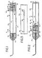
- FIG. 1is a partial longitudinal cross-sectional view of an apparatus for performing intraocular brachytherapy comprising a handpiece, a cannula secured to the handpiece, and a radiation source wire (“RSW”) interior of the handpiece and cannula in a retracted position.
- RSWradiation source wire
- FIG. 2is a cross-sectional view of the apparatus of FIG. 1 with the radiation-emitting element advanced to the treatment position.
- FIG. 3is a top view (as compared to FIGS. 1 and 2 ) of a portion of the housing comprising part of handpiece shown in FIG. 1 .
- FIG. 4is an enlarged view of the cannula associated with the system of FIG. 1 , in partial cross-section.
- FIG. 5is a fragmentary, cross-sectional view of the radioactive source wire forming a portion of the system shown in FIG. 1 .
- FIG. 6is a perspective view of the distal end of the cannula and a dose flattening filter comprising a portion of the tip or distal end of the cannula.
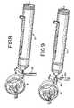
- FIG. 7is an exploded perspective view of a first embodiment of a positioning system for use with the system of FIG. 1 .
- FIGS. 8 and 9illustrate the use of the positioning system of FIG. 7 in connection with the system of FIG. 1 .
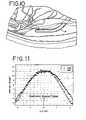
- FIG. 10is an enlarged view showing the treatment of CNV with the device of FIG. 1 .
- FIG. 11shows the dose rate profile at the treatment side of the delivery device.
- FIG. 12is a schematic view of a further version of the cannula for use in the present invention having an inflatable balloon at its distal end.
- FIG. 13is a schematic view of an alternate embodiment of the cannula of FIG. 1 including retractable wires for properly spacing the treatment end of the cannula and the radioactive source from the target tissue.
- FIG. 14is a schematic view of an alternate version of the cannula in which a retractable wire basket is provided for maintaining the proper spacing of the radiation source with respect to the target tissue.
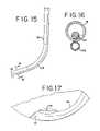
- FIG. 15is a schematic view of a further embodiment of the cannula for use with the present invention in which the cannula includes a lumen for injecting and withdrawing various fluids at the location of the distal end of the cannula.
- FIG. 16is a cross-sectional view of the cannula of FIG. 15 .
- FIG. 17is a schematic view of a further embodiment of the cannula for use in connection with the present invention in which the non-treatment side of the distal end of the catheter is relieved to minimize contact with the retina.
- FIG. 18is a plan view of an alternate embodiment of the cannula and distal end portion of the handpiece for use in the delivery device of FIG. 1 .
- FIG. 19is an enlarged exploded view of the distal end of the cannula shown in FIG. 18 showing the tip, guide tube and cover sleeve.
- FIG. 20is an enlarged top view of the distal end of the cannula shown in FIG. 18 .
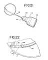
- FIG. 21schematically illustrates the spatial relationship between the tip of the cannula and the target tissue when the device of FIG. 18 is used for the intraocular epiretinal treatment of target tissue.
- FIG. 22is a portion of FIG. 21 enlarged to show detail.
- FIGS. 23 and 24illustrate placement of the treatment cannula in performing the irradiation of the target tissue by the epiretinal method.
- FIGS. 25 and 26show normalized does profiles for a treatment cannula as illustrated in FIG. 24 .
- vitreoretinal surgical techniquesare used to facilitate placement of a radioactive source that preferably, but not exclusively, emits beta or other ionizing radiation, such as gamma or X-ray radiation, temporarily in a subretinal space (with detachment of the retina to gain access to the subretinal space) or an epiretinal space (which does not require detachment of the retina and where the radiation may be transmitted through the retina to the underlying target area) by means of an intraocular cannula, sheath or probe.
- a radioactive sourcethat preferably, but not exclusively, emits beta or other ionizing radiation, such as gamma or X-ray radiation, temporarily in a subretinal space (with detachment of the retina to gain access to the subretinal space) or an epiretinal space (which does not require detachment of the retina and where the radiation may be transmitted through the retina to the underlying target area) by means of an intraocular cannula, sheath or
- an apparatusemploying the radioactive source and a delivery device that permits movement of the source between a stored position and treating position.
- the radiation sourceWhen in the stored (retracted) position, the radiation source is surrounded by a suitable material, such as a stainless steel and lead lining, that effectively protects the surgeon and patient during handling and initial positioning.
- the sourceis preferably located within a specially designed tip of platinum iridium (Pt/Ir), or other suitable material, that provides for directional administration of the radiation with controlled intensity, while shielding and protecting the retina and other surrounding non-target tissues.
- the systemgenerally designated 10 , includes two main components: a radiation source, which may be located at the distal end of a source wire (RSW) 12 and a delivery device 14 that comprises, in the illustrated embodiment, a handle 16 and a delivery cannula 18 (also called a sheath or probe).
- a positioning system 20shown in FIG. 7 , and method, illustrated in FIGS. 8 and 9 , are provided to assist in the precise positioning of the device within the eye.
- Radiation sourceis broadly defined herein, and is not limited to ionizing radiation, light radiation, or heat radiation.
- the radiation sourceis intended to include a treatment source of any of a variety of treatment regimens, including ionizing radiation.
- the radiation source for the RSW 12comprises any suitable radiation source, including radioactive materials such as gamma and beta emitters, x-ray (e.g., miniaturized x-ray generators), and non-ionizing radiation sources, such as laser or other light sources.
- radioactive materialssuch as gamma and beta emitters
- x-raye.g., miniaturized x-ray generators
- non-ionizing radiation sourcessuch as laser or other light sources.
- ultrasound, heat, cryo-ablation, or microwave sourcesmay also be utilized.
- an ionizing radiation source of an essentially beta emitting materialsuch as a Strontium/Yttrium 90 (Sr-90/Y-90) beta emitting isotope
- an ionizing radiation source of an essentially beta emitting materialsuch as a Strontium/Yttrium 90 (Sr-90/Y-90) beta emitting isotope
- the treatment durationis relatively short, approximately 2-4 minutes.
- the system and methodprovide for the delivery of radiation at the site of the choroidal neovascularization that occurs in macular degeneration, or other treatment site.
- the systemWhen employing subretinal ionizing radiation, the system preferably provides radiation to a target site at a dose rate of from approximately 4 to 20 GY/min; with a preferred target dose of between approximately 10 and 40 GY, with the target dose more preferably being approximately 26 GY for neovascularized tissue.
- the preferred embodiment of the radiation sourceincludes a cylindrical aluminum insert 22 that is doped with the Sr-90/Y-90 isotope in accordance with conventional techniques and preferably resides inside a sealed stainless steel canister.
- the canistercomprises a seed tubing 24 sealed on its distal end with a lid 26 and on its proximal end with a lid 28 .
- the stainless steel canistermay be mounted to a solid or braided wire made of stainless steel (or other material) to form the RSW 12 that is used to advance the source to and retract the source from the treatment location.
- the radioactive source wire 12preferably includes a relatively flexible distal or leading strand 30 and a relatively stiffer proximal or handle strand 32 .
- the flexibility of the leading strand 30is such as to allow unimpeded mechanical transport through the cannula 18 around a radius of curvature of from 4 to 8 mm.
- the RSW 12has an overall length on the order of 190 mm, which provides a 10 mm-15 mm protrusion of the wire from the rear of the handle 16 (as seen in FIGS. 1 and 2 ) when the RSW 12 is advanced to the treatment position, thus providing for removal or repositioning of the RSW, if necessary.
- the distal end of the leading strand 30includes a connection tubing 34 closed by a lid 36 for facilitating attachment of the canister housing the radioactive insert 22 .
- a further connection tubing 38is used to join the proximal end of the leading strand 30 to the distal end of the handle strand 32 .
- the leading strand 30has a smaller outside diameter than the handle strand.
- the proximal end of the leading strand 30carries an additional length of tubing 40 to build up the outside diameter of the leading strand 30 to match that of the handle strand.
- the proximal end of the handle strand 32also includes a length of tubing 41 for reinforcement.
- the various components of the RSW 12are preferably made of stainless steel and are joined together by laser welding.
- the radioactive sourcemay not be secured to a wire, and movement of the source canister between treatment and storage positions can be accomplished pneumatically or hydraulically. See, e.g., U.S. Pat. No. 5,683,345, which is incorporated herein by reference.
- the delivery device 14is preferably, but not necessarily, handheld to facilitate control and positioning of the delivery cannula 18 during use.
- the radiation source 22e.g., a beta radiation source
- the handle 16includes a slider mechanism to which a proximal portion of the RSW 12 is secured, the slide mechanism being moveable between treatment position ( FIG. 2 ), in which the radioactive source 22 is positioned at the distal end of the cannula 18 , and a retracted position ( FIG. 1 ) for storage of the radioactive source 22 within the handle 16 .
- the radiation sourceis preferably shielded by a combination of stainless steel (inner shield) and lead (outer shield).
- the stainless steel shieldblocks the beta radiation, while the lead shield reduces the secondary radiation (known as brehmsstrahlung).
- Other suitable materialsmay also be used for shielding.
- the handle 16comprises a multi-part housing with an elongated cylindrical case 42 closed at its proximal end by end cap 44 and at its distal end by a central hub 46 , to which the cannula 18 is secured.
- the hub 46is preferably made of stainless steel and serves as the inner radiation shield for the radioactive source when in the storage position.
- the wall thickness of the shielding portion of the hubis approximately 1.9 mm.
- the hub 46also carries the lead outer shield, designated 48 , which has a wall thickness of approximately 4.6 mm.
- the hub 46 and outer shield 48are carried by a cup-like retaining member 50 that is secured to the distal end of the case 42 .
- the handle 16includes an advancement or positioning mechanism (also referred to as a slider mechanism), generally designated 52 , for moving the radioactive source 22 between the storage and treatment positions.
- the slider mechanism 52includes a carrier member 54 that is slidingly received on the interior of the cylindrical case 42 of the handle 16 .
- the carrier 54includes a central aperture, through which the handle strand 32 of the RSW 12 extends, with the RSW 12 being secured to the carrier 54 by means of a set screw 56 .
- an actuator pin 58that extends through an elongated slot 60 in the case 42 is secured to the carrier 54 .
- the slot 60lies in a plane defined by the curved cannula 18 , thus having the same orientation as the cannula curve.
- the slot 60permits approximately 60 mm, or less, of travel for the carrier 54 and includes offsets 62 , 64 at its distal and proximal ends, respectively, for receiving the actuator pin 58 , thus providing positive visual and tactile indications of the radioactive source 22 being located in the treatment and storage positions.
- the proximal side of the carrier 54also includes a coil spring 66 secured thereto by screw 68 for biasing the actuator pin into a locked condition within proximal offset 64 when in the retracted position.
- the intraocular probe 18is preferably an integral part of the delivery device, and is fabricated of a rigid material, such as stainless steel.
- the probe, or cannula, in the illustrated embodiment,comprises a single lumen and is sealed at the distal end to prevent contact between the radiation source and the patient or the patient's bodily fluids.
- the distal end of the probeincludes an inner sleeve 70 (best seen in FIG. 6 ) in which the radiation source is located when in the treatment position.
- the inner sleeve 70is configured to provide a desired dose profile, which is discussed in greater detail below.
- the inner sleeve 70is received in a cover sleeve 72 that serves to seal the inner sleeve 70 and also provides some radiation attenuation.
- the distal end of the cannula 18is curved or bent at an angle to facilitate proper alignment of the radiation source and the treatment area.
- the tip 74 of the probe 18also preferably has a rounded wedge shape to facilitate positioning of the distal end under the retina, when the retina is partially detached and raised to form a “bleb” (as by injection of saline or other liquid under the retina) during the performance of the method.
- the treatment side of the tipincludes a molded, machined or otherwise formed window 76 (sealed by the cover sleeve 72 ) that allows for directional administration of radiation.
- the window 76is subdivided into four smaller windows by longitudinal and transverse splines 77 that intersect at centrally located solid area 79 that acts as a flattening filter to reduce the peak radiation from the source 22 received by tissue closest to the radiation source. As a result, the tissue to be irradiated at the treatment site receives a more uniform dosage.
- This flattening effectis shown in FIG. 11 , which plots the dose rate (in GY/min) as a function of radial and axial distance from the radiation source center. As can be seen in FIG.
- the peak dose rateis generally flat at the center of the source, and decreases essentially linearly as the distance from the center increases.
- the flattening filterpreferably comprises a shield of selected thickness and/or material suspended in the window at the point closest the treatment site that attenuates or blocks a portion of the radiation from escaping the probe.
- FIG. 7A first embodiment of a system 20 for precise positioning of the probe 18 is shown in FIG. 7 .
- the positioning system 20is adapted to space the probe tip a set distance away from the target tissue and, as such, is particularly suited for the subretinal approach.
- the positioning system 20comprises a base 80 and contact extension 82 which serve as a reference member and are adapted to be mounted to the extra-ocular portion of the sheath or probe 18 .
- a spring 84is located on the probe 18 to provide a positive engagement of the contact extension 80 (when carried on the base 82 ) against the sclera during initial placement. See FIGS. 8 and 9 .
- the base 80For purposes of assembly onto the probe, the base 80 has a slot 86 sized to fit over the probe 18 so that it can be placed thereon.
- the contact extension 82also has a slot 88 thereon to facilitate placement on the probe 18 distally of the base 80 .
- the contact extension 82designed to seat on the base 80 and is maintained in position thereon by frictional engagement.
- a handle 90is provided that has a threaded end 92 that is received in a complimentarily-threaded aperture 94 in the base 80 .
- the threaded end 92 of the handle 90serves as a set screw to secure the base 80 in position on the probe 18 after initial placement, as will be discussed in greater detail below.
- the positioning system 78may be made of any suitable material, but is preferably made of acetal.
- the probeis initially positioned, with the tip 74 of the probe in light contact with the target area to be irradiated, touching either the retina or the retinal pigment epithelium (RPE) tissue under the retina.
- the spring 84pushes the contact extension 82 mounted on the base 80 into contact with the sclera.
- the handle 90is then turned to engage against the probe 18 , thus locking the base 80 into position on the probe 18 .
- the probe 18is then withdrawn from the eye.
- a spacer 96which also has a slot 98 that permits it to be placed on the probe 18 , is then placed between the base 80 and the contact extension 82 , as seen in FIG. 9 , to accurately set the distance between the treatment area and the probe tip 74 .
- the spacer 96has a thickness of from about 0.5 to 3 mm, and preferably 1-1.5 mm (more preferably 1 mm), so as to create a space of the same distance between the tip 74 of the probe 18 and the target area.
- the particular spacingmay vary with the eye disorder treated, the radiation source being used, and the size of the treatment area.
- a spacing of 1-2 mm (and preferably 1.5 mm)is the anticipated spacing for treating the neovascularized tissue associated with macular degeneration with a beta radiation source as described earlier.
- the contact extensionrests against the sclera, resisting or preventing further axial movement of the delivery device into the eye.
- positioning of the probe tipcan be facilitated by the use of intra-ocular ultrasound or doppler measurement of the distances between the distal end of the cannula and the target tissue.
- the distal end of the cannulamay include an ultrasound or doppler transducer (communicating with a read-out device) to both transmit and receive ultrasound or doppler waves.
- the data generated therebyis analyzed in real time, and a calculated measurement of the distance is presented on an optical readout or indicator.
- optical interferometry devices and techniquescan be employed for measuring the distance between the cannula tip and the target tissue.
- the tip of the probe 18may include one or more balloons 100 that are inflatable upon locating the probe tip under the retina (R) in the bleb to insure for spacing of the probe tip between the retina and treatment zone.
- the distal end 101 of the probe 18can be at an angle with respect to the axis of the probe where the radioactive source is located when in the treatment position (again shown in FIG. 12 —see also FIGS. 15 and 17 ). The angled distal end 101 insures that a pre-determined minimum distance is maintained between the radioactive source and the target tissue.
- a preformed wire, or series of wires 102are extendable from a lumen 104 in the probe to properly space or bump-off the probe tip from the treatment zone when advanced out of the lumen.
- a further alternative, shown in FIG. 14is to use a retractable wire basket 106 that is advanced through a lumen 104 in the probe when the probe is placed at the treatment site.
- a still further alternativeis to secure a optic fiber to the probe that extends beyond the distal end an amount corresponding to the desired spacing. When the optic fiber contacts the target tissue, the fiber darkens, thus alerting the surgeon to the desired spacing.
- the basic procedure for sub-retinal intraocular brachytherapyis accomplished through standard vitrectomy and retinal detachment techniques, with the basic steps as follows.
- the surgeonconfirms the location of the target tissue using retinal vascular landmarks and identifies the preferred location of the sclerotomy entry point (i.e., temporal, nasal, etc.) in order to limit exposure of the fovea during treatment.
- the surgeonwill also want to confirm that the radiation source is properly positioned in the probe, when advanced to the treatment position.
- the subjectis prepared pursuant to standard vitrectomy procedures. Specifically, the pupil of the subject is dilated and the patient is positioned ventrally on the operating table. After appropriate cardiac and respiratory monitoring is established, and appropriate anesthesia is induced, the eye is anesthetized, such as with a retrobulbar or peribulbar anesthesia.
- a speculumis placed to secure the eye lid, and surgery typically begins with a conjunctival incision into the superotemporal, superonasal and inferotemporal quadrants of the eye to be treated.
- a scleral incisionis made approximately 3 to 4 mm away from the surgical limbus in the inferotemporal quadrant, and an infusion cannula is inserted into the vitreous cavity.
- the infusion lineis opened and a second and third scleratomy are created 3 to 4 mm away from the surgical limbus in locations determined prior to commencement of the surgery in the superonasal quadrant.
- An appropriate lens for vitreoretinal surgeryis positioned and a vitrectomy performed, a standard endoilluminator (a fiber optic light source) being used to illuminate the vitreous cavity.
- the treatment probeis positioned.
- any of a number of different positioning techniques as described hereinmay be used. If the positioning system as illustrated in FIGS. 7-9 is used, the spring 84 of the positioning system 20 is carefully slid over the probe 18 up to the device handle 16 , and the positioning system is placed on to the probe shaft without the spacer element 96 . See FIG. 8 . The sclerotomy is extended to a length of approximately 1.0-1.3 mm, and the delivery probe is inserted through the sclerotomy incision into the vitreous cavity.
- the surgeonplaces the tip of the probe directly above the macula. Specifically, the probe is positioned by gently touching the retinal tissue, while directly holding the probe center marker (a mark on the probe tip designating the center of the radiation source) above the center of the CNV complex. While the surgeon holds the probe steady at this position, the positioning system (base 80 and contact extension 82 ) without the spacer 96 is secured onto the external portion of the delivery probe while in contact with the sclera to identify the precise location of the probe as it contacts the retina by tightening the handle, and the cannula is removed from the vitreous cavity. The spacer 96 is then placed between the positioning system base 80 and the contact extension 82 , as shown in FIG. 9 .
- a localized retinal detachment(the “bleb”) is created by using a sub-retinal infusion needle in the macular region, the bleb including the area of choroidal neovascularization.
- a new retinotomyis created on the temporal edge of the bleb, with the new incision created less than 4 mm away from the fovea to reduce the risk of a peripheral retinal tear.
- the retinotomyis approximately 1.0-1.3 mm in diameter in order to accommodate the probe.
- the delivery device probe 18is then reinserted into the vitreous cavity and into the sub-retinal space through the second retinotomy, as seen in FIG. 10 .
- the distal end of the probeis positioned directly above the target (such as the center of the CNV complex or fovea) with the positioning system touching the sclera, thus insuring the distance of the probe tip is about 1.5 mm above the target area.
- the radiation doseis delivered to the target tissue.
- the radiation sourceis advanced by pushing the slider mechanism towards the tip of the probe. Once advanced, the source wire is locked into position by locating the pin in the detent 62 . After the appropriate treatment time, the slider mechanism is retracted to bring the radioactive source back to the storage and locked position. After insuring that the radioactive source has been fully retracted into its storage position, the delivery probe is removed from the bleb and withdrawn from the eye.
- the retinaAfter removal of the probe, the retina is then reattached intraoperatively, and a complete fluid-air exchange is performed, resulting in an air or gas tamponade in the vitreous cavity.
- the retinotomyis closed by, e.g., laser photocoagulation, if necessary, while the superior sclerotomy is closed with ophthalmic sutured.
- the inferotemporal sclerotomyis closed, and the conjunctiva is sutured with appropriate ophthalmic sutures. Antibiotics and steroids may then be administered in the sub-conjuctival space.
- the retina and other non-target tissue during treatmentmay be shielded and protected by introducing a radiation-attenuating fluid into the bleb that is created by lifting the retina away from the CNV.
- the fluidcan consist of saline, or a fluid with higher attenuation coefficient, such as contrast media.
- the use of a radiation-attenuating fluid to protect non-target tissuemay also be advantageous during epi-retinal and epi-scleral applications of radiation. In such cases, the radiation-attenuating fluid is merely introduced into the vitreous cavity, rather than into the sub-retinal space.
- the bleb shapemay be maintained in several different ways.
- the bleb shapemay be maintained by injecting a high viscosity material into the sub-retinal space created by the bleb. Because of the material's high viscosity, its ability to flow through the retinotomy is reduced. The high viscosity material is removed, after treatment, using a standard vitrectomy device.
- a high density materialis a sodium hyaluronate preparation for ophthalmic use sold by Pharmacia Company, under the trademark HEALON®.
- a substance with variable viscosity having a high initial viscosity during the treatment time, with a lower viscosity thereafter,would further facilitate the removal of the material form the sub-retinal space upon completion of the procedure.
- a sealing substancesuch as HEALON®
- An inflation agentsuch as saline
- salinecan also be continuously introduced into the sub-retinal space with a small positive pressure by means of an open lumen 108 associated with the cannula 18 ( FIGS. 15 , 16 ).
- the distal end of the cannulacan be provided with a balloon ( FIG. 12 ) that is inflated after the distal end of the cannula is introduced into the bleb in order to support the bleb and prevent the bleb from deflating or collapsing.
- the need to do a vitrectomy prior to introducing the probemay also be reduced or eliminated if the cannula has a low-friction surface.
- Thiscan be provided by coating the probe with a lubricant or other coating, such as Teflon or electrolytic carbon, or providing the cannula with a highly-polished surface, as by electro-polishing.
- the backside 110 of the probei.e., the non-treatment side
- the area of the incision resulting from the vitrectomy performed to create the blebmay be cauterized to prevent or limit retinal bleeding.
- Such cauterizationmay be achieved by diathermy, cryopexy, or the application of laser or RF energy using instrumentation and methods known for re-attaching the retina to the retinal pigment epithelium (RPE) in the case of retinal detachment.
- RPEretinal pigment epithelium
- blood coagulantssuch as antihemophilic Factor VIII (recombinant) (available from Bayer Healthcare as Kogenate), aminocaproic acid (available form Immunex as Amicar), and desmopressin acetate (available from Rhone Poulanc Rorer as Octostim), may also be injected into the sub-retinal space to limit bleeding by means of the separate lumen associated with the treatment device, as shown in FIGS. 15 , 16 .
- the coagulantmay also be removed through the same lumen.
- Injection of an iron-binding substancesuch as apotransferrin
- into the bloodmay also be used in facilitating the removal of blood from the sub-retinal space and preventing its oxidation.
- an anti-proliferating drug(anti-Vascular Endothelial Growth Factor or anti-VEGF agent, such as Macugen (pegaptanib sodium), Avastin or Lucentis) may be injected into the sub-retinal space, or applied epiretinally, to prevent and/or limit further growth of the CNV.
- anti-proliferating drugsuch as Macugen (pegaptanib sodium), Avastin or Lucentis
- the tip of the probeinclude an inflatable balloon that causes pressure on the retina when inflated to reduce the blood flow thereto, the radiation treatment being performed through, the balloon.
- a deployable maskmade of a radiation-blocking material that will be deployed and located over the non-target tissue, while leaving the target tissue exposed.
- a materialcould be carried by the tip of probe 18 or by a separate device and deployed after formation of the bleb. The material could be biodegradable if desired.
- AMDmay be treated by exposing the subretinal target area to ionizing radiation that passes through the retina, without causing undue harm to the retina.
- the delivery device of the present inventionmay also be used in methods for intraocular, epiretinal application of radiation, in which no bleb is created, and the target tissue is irradiated through the retina.
- the target area or regionmay be centered on or include the fovea, or the target region may be a separate lesion area, such as an area of leaking blood vessels identified by dye or other visualizations techniques.
- the target regionis typically no more than about 5-6 mm in diameter or width in the illustrated embodiment, and the delivered radiation dosage drops from a peak dosage in the center of the target region to preferably not more than about 20% of the peak dosage at about 3 mm from the center. Outwardly from 3 mm, the delivered radiation dose drops exponentially so that relatively little, if any radiation dosage is delivered substantially outside the target region.
- FIG. 26illustrates a dose distribution as it varies from the center peak value.
- the X and Y axisgenerally represent distance from the center and curves or circles within the figure represent the percentage of peak dose. For example, along the X axis it may be seen that the delivered dose at a distance of about 3 mm from the center is about 20% of the peak delivered dose.
- the dose distributionis not perfectly circular and reference to diameter or distance from center or width is approximate. As the distance increases from the center, the delivered dose drops off rapidly, assuring that area of the retina substantially outside the target area receives minimal radiation exposure. This highly localized application of radiation, which will be discussed in more detail later, minimizes potentially detrimental levels of exposure of the retina to radiation, and is particularly beneficial to maintaining visual acuity.
- a radiation delivery devicehaving a distal end particularly suited for the epiretinal application of radiation is disclosed in FIG. 18 .
- the proximal portion of the delivery device and the radiation source wireare similar to one or more of the embodiments described above.
- the distal end of the delivery device, generally designated 110includes a cannula 112 that is mounted to the case 42 of the handle 16 of the delivery device. This is accomplished in the illustrated embodiment by means of a central hub 114 , outer shield 116 , and retaining member 118 that are similar to the central hub 46 , outer shield 48 , and retaining member 50 described above in connection with FIGS. 1-3 .
- a grip portion 120is secured to the distal end of the central hub 114 .
- the grip portion 120has a generally cylindrical proximal portion and a conical distal portion.
- the cylindrical portionhas opposed flat sections 122 (one such surface shown in FIG. 18 ). These irregular surfaces 122 facilitate holding the delivery device with a pencil-like grip between the thumb and/or fingers of the surgeon. However, other gripping surfaces may be used as ergonomically appropriate.
- the flats 122lie in planes parallel to a plane defined by the cannula and aligned with a positioning sleeve located at the distal end of the cannula to assist in the proper orientation of the cannula and directional application of radiation during a procedure.
- the grip portion 120provides additional shielding of the user from radiation as the radiation source wire is advanced and retracted, as well as provides strain relief at the attachment point of the cannula 112 to the delivery device.
- the same structuremay also be used in the subretinal approach, and the apparatus of FIGS. 1-3 may be modified to include such a gripping/shielding portion.
- the cannula 112is preferably sized to fit through a standard vitrectomy trocar and, thus, has an outside diameter of no more than 1.0 mm.
- the distal end or tip portion 124 of the cannula 112is formed so that its axis is preferably at an angle ⁇ of about 30°, and more preferably of 31.33°, with respect to the axis of the proximal portion 126 of the cannula.
- a curved transition portion 128joins the distal end portion to the proximal portion.
- the cannula 112may be straight from its proximal end to its distal end, with no bend at the tip.
- the tip portion 124 of the cannulais shown in an exploded view in FIG. 19 . It includes a solid tip member 130 having a rounded, non-traumatic end 132 and a shoulder 134 for seating the end of a cover sleeve 136 .
- Other configurationsmay be employed for the tip member 130 , such as the angled configuration shown in FIGS. 12 , 15 , and 17 .
- the tip 130may be made of stainless steel, or made from or coated with a softer, atraumatic material such as silicone.
- the distal end of the cannulapreferably carries a visual indicator viewable through the lens of the eye during surgery to identify when the radiation source (when introduced into the cannula) will be properly positioned relative to the target area for the desired radiation exposure.
- the top of the cover sleeve 136is preferably inscribed with a cross-mark 138 located 4.215 mm from the end of the cannula.
- the cross-mark 138represents the center of dose distribution and facilitates properly locating the distal end of the cannula 112 with respect to the target tissue by usually centering the cross-mark 138 over the fovea 140 or other target area, as illustrated in FIGS. 21 and 22 .
- the position of the cross-mark 138will vary depending upon the angle ⁇ of the tip portion 124 with respect to the axis of the cannula 112 .
- Other indicia or techniques for positioning the distal end of the cannulamay also be used as discussed herein.
- the cover sleeve 136 and tip member 130have a combined length of 4.75 mm, and comprise the distal-most straight portion of the cannula.
- a guide sleeve or partial guide tube 140may be located interior of the cover sleeve 136 , and secured to the tip member 130 by, e.g., laser welding.
- the guide tube 140serves to bias the radiation source into close proximity with the sidewall of the cover sleeve 136 adjacent the target tissue to insure consistent positioning of the radioactive source within the cannula and a more predictable dosing of the target tissue.
- this position of the radiation sourceis fixed relative to the gripping flats 122 , so that the surgeon knows tactilely that the radiation source is properly oriented relative to the target tissue.
- the guide tube 140is only partially radially coextensive with the cover sleeve 136 and, as illustrated, has an arcuate or semicircular cross-section.
- the proximal end 142 of the guide tube 140is inclined or beveled to facilitate entry of the tip of the source wire into the distal tip of the cannula.
- the bevelis preferably at an angle of 25° with respect to the longitudinal axis of the guide tube 140 .
- the guide tube 140also provides directional shielding for the non-target tissue.
- Performance of the epiretinal methodis substantially easier then the subretinal approach.
- Intraocular accessmade simply through a sclerotomy, and the distal end of the probe is located over the macula. No detachment of the retina or the creation of a bleb is required.
- Accurate placement of the probemay be accomplished by any of the positioning systems described. Ultrasound or Doppler techniques known in the art may also be used. Other mechanical methods may also be used, such as putting a stand-off fiber or “whisker” on the tip of the probe that touches the retina when the probe is properly positioned. Alternatively, an inflatable balloon that, when inflated, spaces the probe the desired distance from the target tissue can also be used.
- Trocarsmay be placed in the sclerotomy incisions to facilitate the introduction of the various cannulas into the vitreous cavity.
- the specific geometry/configuration of the cannula and tipmay vary.
- the sclerotomy for the entry of the cannula into the eyeshould always be made the same distance form the surgical limbus—between approximately 3.0-4 mm—, and the tip of the cannula should touch the retina outside of the fovea but within the field of view of the surgical microscope, so that the device can deliver the intended dose to the target tissue.
- the treatment probeis positioned.
- the cannula 112is inserted into the vitreous cavity and positioned over the target tissue, using the cross-mark 138 on the cannula tip as an alignment aid.
- the non-traumatic tipis brought into gentle contact with the retina which, because of the geometry of the cannula, will provide the appropriate distance between the center of the radiation source (when the radiation source advanced to the treatment portion of the cannula) and the treatment site of between approximately 2-6 mm, (more preferably approximately 2-3 mm and specifically about 2.6 mm).
- the radiation sourcewill deliver the prescribed dose in from approximately 2 to 5 minutes.
- the appropriate gentle contact of the tip of the cannula with the retinamay be achieved visually by the surgeon in the following manner.
- a shadowis cast on the back of the eye that is spaced from the tip of the cannula.
- the shadowconverges toward the cannula and the lighted area between the shadow and the cannula becomes smaller.
- the lighted areais eliminated as the tip of the cannula touches the retina/target tissue, thus indicating to the surgeon contact of the cannula with the retina.
- the radiation doseis delivered to the target tissue by advancing the radiation source with the slider mechanism, as described above. After the appropriate treatment time, the slider mechanism is retracted to bring the radioactive source back to the storage and locked position. The delivery probe is then withdrawn from the eye. After removal of the probe, the sclerotomy is closed using conventional surgical techniques and the infusion needle removed. The conjunctiva is closed and antibiotics and steroids are administered in the sub-conjunctival space.
- the spacing between the radiation source and the target tissuemay vary depending upon the shape of the cannula, (i.e., straight shaft or bent shaft) and the geometry of the tip (e.g., angled— FIGS. 12 , 15 , 17 , or straight/blunt— FIGS. 18-22 ).
- the greater the space between the radiation source and the target tissuethe longer the exposure time required to deliver a specified dose to the target tissue.
- the greater the space between the radiation source and the target tissuethe flatter the dose profile (i.e., the more even the dosing) for the target tissue.
- the radiation sourcepreferably has an activity level of approximately 5-20 mCi, and is more preferably approximately 11-13 mCi.
- the dose delivered to the target tissuemay vary from between about 7 Gy (the lowest dose currently believed to be therapeutically effective) and 50 Gy (the dose for which initial signs of radiation acute toxicity have been observed). It is presently contemplated that the preferred dosage will not exceed about 30 Gy and will be in a range of from 20-30 Gy. Therefore, the preferred dosage directed to the target tissue, which may be centered above the fovea or centered above a lesion site spaced from the fovea, depending on the surgeon's selection, is preferably between about 7 and 50 Gy, with a more preferred range between 20 and 30 Gy. A peak dose of about 24 Gy is presently deemed most preferable.
- This treatment timeserves to minimize surgical complications, while still delivering a prescribed radiation dose from a source within an acceptably-low activity level.
- the area of the retina outside the target regionis exposed to significantly less radiation, with the amount of delivered radiation dose decreasing exponentially from the target center.
- the delivered doseis about 20% of the peak at about 3 mm from the center.
- the delivered dose at this distancemay vary from about 1.4 Gy to about 10 Gy for a peak dose of 7-50 Gy, and from about 4 Gy to 6 Gy for a preferred peak dose of 20-30 Gy.
- the dosagedrops off quickly so that radiation exposure is substantially limited to the target area, and dosage outside the target area is less than about 10 Gy and more preferably less than 6 Gy in the vicinity of the retina adjoining the target region decreasing significantly with increased distance beyond the target region.
- FIGS. 12 , 15 and 17the center of the source is spaced about 2.6 mm from the retina, as generally illustrated in FIG. 23 .
- a source having an activity level of approximately 6 mCia 15 Gy peak dose was delivered in 3-5 minutes.
- a tip 130 as shown in FIGS. 18-22a similar spacing of 2.6 mm from the center of the source to the retina is obtained, as generally illustrated in FIG. 24 .
- a peak dose of 24 Gywas delivered in 3-5 minutes.
- 25 and 26are normalized dose rate profiles for the treatment cannula of FIG. 24 , showing the does rate distribution axially and radially with respect to the radioactive source ( FIG. 25 ) and topographically ( FIG. 26 ). If the cannula has a straight shaft, the center of the radiation source will be spaced approximately 4 mm from the retina, and it is contemplated that the source will have an activity level of 20 mCi in order to deliver the prescribed dose in the appropriate amount of time.
- the radiation sourceis described as a beta radiation emitting source, other ionizing radiation sources may be used, such as gamma or X-ray sources. Such sources may require different exposure times, spacing from the target area and shielding to afford therapeutic benefit without undue harm to non-target areas of the retina.
- Potential miniature X-ray sourcesmay include sources such as those described in published U.S. applications Nos. 2003/0179854 A1 and 2005/0038488 A1, both of which are incorporated by reference herein.
- beta radiation and soft X-ray radiationwhich may be selected to mimic the characteristics of beta radiation with low energy voltage sources, are presently preferred to reduce or minimize the volume of the radiation to which the body is exposed.
- gamma or other ionizing radiationmay also be suitable.
- a miniature radiation sensorthat can be remotely interrogated may be placed on the retinal surface, and the distance between the probe tip and the surface of the retina can be determined based upon the level of radiation measured by the sensor. If multiple (i.e. 3) sensors are used, triangulation of the measured radiation intensity would provide an accurate measurement of position. If multiple (i.e. 3) sensors are used, triangulation of the measured radiation intensity would provide an accurate measurement of position. If at least three miniature event counters or sensors are positioned in an array on the periphery of the retina equidistant from the target tissue, the intensity/frequency of events measured by each point can be analyzed and then compared.
- the position of sourcethen can be determined through well-known three-dimensional triangulation calculations at the beginning of the radiation administration.
- the event counters/sensorscan be placed either in the eye, behind the eye, or even on the front surface of the eye, if the radiation source produced a sufficient emission to be measured externally.
- the radiation sourcecan carry a small transducer on its tip that would emit a “ping” that can be picked up by receivers positioned as described above.
- Other signaling/receiving systemssuch as light or RF can also be used.
- a permanent magnet disposed on the tip of the devicecould produce a sufficient Galvanic effect in appropriate sensors to be measurable, especially in an epi-retinal application where the size constraints of the device are less critical. A digitally-enclosed signal would provide improved speed and accuracy.
Landscapes
- Health & Medical Sciences (AREA)
- Biomedical Technology (AREA)
- Engineering & Computer Science (AREA)
- Radiology & Medical Imaging (AREA)
- Pathology (AREA)
- Nuclear Medicine, Radiotherapy & Molecular Imaging (AREA)
- Ophthalmology & Optometry (AREA)
- Life Sciences & Earth Sciences (AREA)
- Animal Behavior & Ethology (AREA)
- General Health & Medical Sciences (AREA)
- Public Health (AREA)
- Veterinary Medicine (AREA)
- Surgical Instruments (AREA)
- Radiation-Therapy Devices (AREA)
Abstract
Description
Claims (7)
Priority Applications (5)
| Application Number | Priority Date | Filing Date | Title |
|---|---|---|---|
| US11/228,030US7563222B2 (en) | 2004-02-12 | 2005-09-15 | Methods and apparatus for intraocular brachytherapy |
| PCT/US2006/031004WO2007040825A2 (en) | 2005-09-15 | 2006-08-09 | Methods and apparatus for intraocular brachytherapy |
| US11/559,958US7803103B2 (en) | 2005-02-11 | 2006-11-15 | Methods and apparatus for intraocular brachytherapy |
| US12/887,996US8292795B2 (en) | 2005-02-11 | 2010-09-22 | Methods and apparatus for intraocular brachytherapy |
| US13/604,212US20120330088A1 (en) | 2004-02-12 | 2012-09-05 | Methods and Apparatus for Intraocular Brachytherapy |
Applications Claiming Priority (3)
| Application Number | Priority Date | Filing Date | Title |
|---|---|---|---|
| US54400104P | 2004-02-12 | 2004-02-12 | |
| US11/056,763US7744520B2 (en) | 2004-02-12 | 2005-02-11 | Method and apparatus for intraocular brachytherapy |
| US11/228,030US7563222B2 (en) | 2004-02-12 | 2005-09-15 | Methods and apparatus for intraocular brachytherapy |
Related Parent Applications (1)
| Application Number | Title | Priority Date | Filing Date |
|---|---|---|---|
| US11/056,763Continuation-In-PartUS7744520B2 (en) | 2004-02-12 | 2005-02-11 | Method and apparatus for intraocular brachytherapy |
Related Child Applications (1)
| Application Number | Title | Priority Date | Filing Date |
|---|---|---|---|
| US11/559,958Continuation-In-PartUS7803103B2 (en) | 2004-02-12 | 2006-11-15 | Methods and apparatus for intraocular brachytherapy |
Publications (2)
| Publication Number | Publication Date |
|---|---|
| US20060111605A1 US20060111605A1 (en) | 2006-05-25 |
| US7563222B2true US7563222B2 (en) | 2009-07-21 |
Family
ID=37906631
Family Applications (1)
| Application Number | Title | Priority Date | Filing Date |
|---|---|---|---|
| US11/228,030Expired - Fee RelatedUS7563222B2 (en) | 2004-02-12 | 2005-09-15 | Methods and apparatus for intraocular brachytherapy |
Country Status (2)
| Country | Link |
|---|---|
| US (1) | US7563222B2 (en) |
| WO (1) | WO2007040825A2 (en) |
Cited By (24)
| Publication number | Priority date | Publication date | Assignee | Title |
|---|---|---|---|---|
| US20090054874A1 (en)* | 2007-08-23 | 2009-02-26 | C. R. Bard, Inc. | Multi-lumen catheter including a lumen having a variable cross sectional area |
| USD615645S1 (en)* | 2009-02-06 | 2010-05-11 | Luca Brigatti | Fixed-shape cannula for posterior delivery of radiation to eye |
| USD616087S1 (en)* | 2009-02-06 | 2010-05-18 | Luca Brigatti | Fixed-shape cannula for posterior delivery of radiation to eye |
| USD616088S1 (en)* | 2009-02-06 | 2010-05-18 | Luca Brigatti | Fixed-shaped cannula for posterior delivery of radiation to eye |
| USD616540S1 (en)* | 2009-02-06 | 2010-05-25 | Luca Brigatti | Fixed-shape cannula for posterior delivery of radiation to eye |
| US20110021906A1 (en)* | 2005-02-11 | 2011-01-27 | Hillstead Richard A | Methods and Apparatus for Intraocular Brachytherapy |
| USD642266S1 (en) | 2010-08-24 | 2011-07-26 | Marsteller Laurence J | Brachytherapy device |
| US8430804B2 (en) | 2008-01-07 | 2013-04-30 | Salutaris Medical Devices, Inc. | Methods and devices for minimally-invasive extraocular delivery of radiation to the posterior portion of the eye |
| USD691268S1 (en) | 2009-01-07 | 2013-10-08 | Salutaris Medical Devices, Inc. | Fixed-shape cannula for posterior delivery of radiation to eye |
| USD691270S1 (en) | 2009-01-07 | 2013-10-08 | Salutaris Medical Devices, Inc. | Fixed-shape cannula for posterior delivery of radiation to an eye |
| USD691269S1 (en) | 2009-01-07 | 2013-10-08 | Salutaris Medical Devices, Inc. | Fixed-shape cannula for posterior delivery of radiation to an eye |
| USD691267S1 (en) | 2009-01-07 | 2013-10-08 | Salutaris Medical Devices, Inc. | Fixed-shape cannula for posterior delivery of radiation to eye |
| US8602959B1 (en) | 2010-05-21 | 2013-12-10 | Robert Park | Methods and devices for delivery of radiation to the posterior portion of the eye |
| US8608632B1 (en) | 2009-07-03 | 2013-12-17 | Salutaris Medical Devices, Inc. | Methods and devices for minimally-invasive extraocular delivery of radiation and/or pharmaceutics to the posterior portion of the eye |
| US20140142663A1 (en)* | 2012-11-20 | 2014-05-22 | Biolase, Inc. | Eyelid Treatment Device |
| US9056201B1 (en) | 2008-01-07 | 2015-06-16 | Salutaris Medical Devices, Inc. | Methods and devices for minimally-invasive delivery of radiation to the eye |
| USD808529S1 (en) | 2016-08-31 | 2018-01-23 | Salutaris Medical Devices, Inc. | Holder for a brachytherapy device |
| US9873001B2 (en) | 2008-01-07 | 2018-01-23 | Salutaris Medical Devices, Inc. | Methods and devices for minimally-invasive delivery of radiation to the eye |
| USD808528S1 (en) | 2016-08-31 | 2018-01-23 | Salutaris Medical Devices, Inc. | Holder for a brachytherapy device |
| USD814637S1 (en) | 2016-05-11 | 2018-04-03 | Salutaris Medical Devices, Inc. | Brachytherapy device |
| USD814638S1 (en) | 2016-05-11 | 2018-04-03 | Salutaris Medical Devices, Inc. | Brachytherapy device |
| USD815285S1 (en) | 2016-05-11 | 2018-04-10 | Salutaris Medical Devices, Inc. | Brachytherapy device |
| US10022558B1 (en) | 2008-01-07 | 2018-07-17 | Salutaris Medical Devices, Inc. | Methods and devices for minimally-invasive delivery of radiation to the eye |
| USD841164S1 (en)* | 2015-12-16 | 2019-02-19 | Novartis Ag | Intraocular lens delivery device |
Families Citing this family (22)
| Publication number | Priority date | Publication date | Assignee | Title |
|---|---|---|---|---|
| US8123698B2 (en)* | 2002-10-07 | 2012-02-28 | Suros Surgical Systems, Inc. | System and method for minimally invasive disease therapy |
| US8172770B2 (en) | 2005-09-28 | 2012-05-08 | Suros Surgical Systems, Inc. | System and method for minimally invasive disease therapy |
| US7563222B2 (en) | 2004-02-12 | 2009-07-21 | Neovista, Inc. | Methods and apparatus for intraocular brachytherapy |
| EP1720608B1 (en) | 2004-02-12 | 2010-11-17 | NeoVista, Inc. | Apparatus for intraocular brachytherapy |
| JP2008526418A (en)* | 2005-01-18 | 2008-07-24 | コーニンクレッカ フィリップス エレクトロニクス エヌ ヴィ | Electronically controlled capsule for emitting radiation |
| US20080200834A1 (en)* | 2005-09-28 | 2008-08-21 | Mark Joseph L | Introducer device for improved imaging |
| US20080070855A1 (en)* | 2006-09-20 | 2008-03-20 | James Pitzer Gills | Treatment with anti-VEGF agents to prevent postoperative inflammation and angiogenesis in normal and diseased eyes |
| US7831309B1 (en) | 2006-12-06 | 2010-11-09 | University Of Southern California | Implants based on bipolar metal oxide semiconductor (MOS) electronics |
| BRPI0913380A2 (en) | 2008-06-04 | 2015-11-24 | Neovista Inc | portable radiation release system for advancing a radiation source wire |
| AU2010213840B2 (en)* | 2009-02-10 | 2014-03-20 | Eyepoint Pharmaceuticals Us, Inc. | Ocular trocar assembly |
| US8663210B2 (en) | 2009-05-13 | 2014-03-04 | Novian Health, Inc. | Methods and apparatus for performing interstitial laser therapy and interstitial brachytherapy |
| WO2011053908A1 (en)* | 2009-11-02 | 2011-05-05 | Salutaris Medical Devices, Inc. | Methods and devices for delivering appropriate minimally-invasive extraocular radiation |
| US8343106B2 (en) | 2009-12-23 | 2013-01-01 | Alcon Research, Ltd. | Ophthalmic valved trocar vent |
| JP5990103B2 (en) | 2009-12-23 | 2016-09-07 | アルコン リサーチ, リミテッド | Ophthalmic valved trocar cannula |
| CA2960278A1 (en) | 2014-09-11 | 2016-03-17 | Psivida Us, Inc. | Injector apparatus |
| US10258502B2 (en)* | 2014-09-18 | 2019-04-16 | Orbit Biomedical Limited | Therapeutic agent delivery device |
| USD851755S1 (en) | 2015-10-22 | 2019-06-18 | Eyepoint Pharmaceuticals Us, Inc. | Ocular inserter |
| GB201714392D0 (en) | 2017-09-07 | 2017-10-25 | Marsteller Laurence | Methods and devices for treating glaucoma |
| US20220212032A1 (en)* | 2017-09-07 | 2022-07-07 | Radiance Therapeutics, Inc. | Ophthalmic brachytherapy systems and devices for application of beta radiation |
| WO2020069217A1 (en)* | 2018-09-28 | 2020-04-02 | Radiance Therapeutics, Inc. | Methods, systems, and compositions for maintaining functioning drainage blebs associated with minimally invasive micro sclerostomy |
| USD1076086S1 (en) | 2021-11-23 | 2025-05-20 | Radiance Therapeutics, Inc. | Opthalmic brachytherapy device |
| USD1076085S1 (en) | 2021-11-23 | 2025-05-20 | Radiance Therapeutics, Inc. | Opthalmic brachytherapy device |
Citations (276)
| Publication number | Priority date | Publication date | Assignee | Title |
|---|---|---|---|---|
| US839061A (en) | 1905-02-23 | 1906-12-18 | Henri Farjas | Apparatus for application of salts of radium. |
| US2517568A (en) | 1948-09-04 | 1950-08-08 | Radium Chemical Company Inc | Eye applicator |
| US2559793A (en) | 1949-01-27 | 1951-07-10 | Canadian Radium And Uranium Co | Beta irradiation method and means |
| GB1211316A (en) | 1968-07-23 | 1970-11-04 | Commissariat Energie Atomique | Apparatus for determining the position of a radioactive source |
| US4198570A (en) | 1978-01-09 | 1980-04-15 | Atomic Energy Of Canada Limited | Unitary self shielded, self filtered and flattened Bremsstrahlung photon source assembly for radiotherapy use |
| US4584991A (en) | 1983-12-15 | 1986-04-29 | Tokita Kenneth M | Medical device for applying therapeutic radiation |
| US4662869A (en) | 1984-11-19 | 1987-05-05 | Wright Kenneth W | Precision intraocular apparatus |
| US4846172A (en) | 1987-05-26 | 1989-07-11 | Berlin Michael S | Laser-delivery eye-treatment method |
| US4861520A (en) | 1988-10-28 | 1989-08-29 | Eric van't Hooft | Capsule for radioactive source |
| US4891165A (en) | 1988-07-28 | 1990-01-02 | Best Industries, Inc. | Device and method for encapsulating radioactive materials |
| US4921327A (en) | 1989-05-24 | 1990-05-01 | Zito Richard R | Method of transmitting an ionizing radiation |
| US4957476A (en) | 1989-01-09 | 1990-09-18 | University Of Pittsburgh | Afterloading radioactive spiral implanter |
| US4996159A (en) | 1985-02-26 | 1991-02-26 | The Johns Hopkins University | Neovascularization inhibitors and methods for their production and use |
| US5084001A (en) | 1986-07-10 | 1992-01-28 | Eric van't Hooft | Method and apparatus for effecting radioactive therapy in an animal body |
| US5123902A (en) | 1988-09-13 | 1992-06-23 | Carl-Zeiss-Stiftung | Method and apparatus for performing surgery on tissue wherein a laser beam is applied to the tissue |
| US5129895A (en) | 1990-05-16 | 1992-07-14 | Sunrise Technologies, Inc. | Laser sclerostomy procedure |
| US5141487A (en) | 1985-09-20 | 1992-08-25 | Liprie Sam F | Attachment of radioactive source and guidewire in a branchy therapy source wire |
| US5147282A (en) | 1989-05-04 | 1992-09-15 | William Kan | Irradiation loading apparatus |
| US5183455A (en) | 1988-10-07 | 1993-02-02 | Omnitron International, Inc. | Apparatus for in situ radiotherapy |
| US5199939A (en) | 1990-02-23 | 1993-04-06 | Dake Michael D | Radioactive catheter |
| US5203353A (en) | 1989-10-24 | 1993-04-20 | Surgical Technologies, Inc. | Method of penetrating and working in the vitreous humor of the eye |
| US5257988A (en) | 1991-07-19 | 1993-11-02 | L'esperance Medical Technologies, Inc. | Apparatus for phacoemulsifying cataractous-lens tissue within a protected environment |
| US5267960A (en) | 1990-03-19 | 1993-12-07 | Omnitron International Inc. | Tissue engaging catheter for a radioactive source wire |
| US5282781A (en) | 1990-10-25 | 1994-02-01 | Omnitron International Inc. | Source wire for localized radiation treatment of tumors |
| US5290585A (en) | 1990-11-01 | 1994-03-01 | C. R. Bard, Inc. | Lubricious hydrogel coatings |
| US5322499A (en) | 1985-09-20 | 1994-06-21 | Liprie Sam F | Continuous sheated low dose radioactive core adapted for cutting into short sealed segments |
| US5342283A (en) | 1990-08-13 | 1994-08-30 | Good Roger R | Endocurietherapy |
| US5354257A (en) | 1991-01-29 | 1994-10-11 | Med Institute, Inc. | Minimally invasive medical device for providing a radiation treatment |
| US5422926A (en) | 1990-09-05 | 1995-06-06 | Photoelectron Corporation | X-ray source with shaped radiation pattern |
| US5426662A (en) | 1994-04-28 | 1995-06-20 | Coherent, Inc. | Laser system selectively operable at two competing wavelengths |
| US5425730A (en) | 1994-02-16 | 1995-06-20 | Luloh; K. P. | Illumination cannula system for vitreous surgery |
| US5431907A (en) | 1994-08-03 | 1995-07-11 | Abelson; Mark B. | Treatment of vascular disorders of the posterior segment of the eye by topical administration of calcium channel blocking agents |
| US5487725A (en) | 1994-05-12 | 1996-01-30 | Syntec, Inc. | Pneumatic vitrectomy for retinal attachment |
| US5503613A (en) | 1994-01-21 | 1996-04-02 | The Trustees Of Columbia University In The City Of New York | Apparatus and method to reduce restenosis after arterial intervention |
| US5503614A (en) | 1994-06-08 | 1996-04-02 | Liprie; Samuel F. | Flexible source wire for radiation treatment of diseases |
| EP0541699B1 (en) | 1990-07-13 | 1996-05-29 | Mallinckrodt Medical, Inc. | Device for introducing a radioactive source into the body |
| US5528651A (en) | 1994-06-09 | 1996-06-18 | Elekta Instrument Ab | Positioning device and method for radiation treatment |
| US5556389A (en) | 1994-03-31 | 1996-09-17 | Liprie; Samuel F. | Method and apparatus for treating stenosis or other constriction in a bodily conduit |
| US5570408A (en) | 1995-02-28 | 1996-10-29 | X-Ray Optical Systems, Inc. | High intensity, small diameter x-ray beam, capillary optic system |
| US5575749A (en) | 1988-08-04 | 1996-11-19 | Omnitron International, Inc. | Ultra-thin high dose radioactive source wire |
| US5596011A (en) | 1995-04-06 | 1997-01-21 | Repine; Karen M. | Method for the treatment of macular degeneration |
| US5618266A (en) | 1994-03-31 | 1997-04-08 | Liprie; Samuel F. | Catheter for maneuvering radioactive source wire to site of treatment |
| US5624437A (en) | 1995-03-28 | 1997-04-29 | Freeman; Jerre M. | High resolution, high speed, programmable laser beam modulating apparatus for microsurgery |
| US5637073A (en) | 1995-08-28 | 1997-06-10 | Freire; Jorge E. | Radiation therapy for treating macular degeneration and applicator |
| US5651783A (en) | 1995-12-20 | 1997-07-29 | Reynard; Michael | Fiber optic sleeve for surgical instruments |
| US5688220A (en) | 1994-06-10 | 1997-11-18 | Schneider (Europe) A.G. | Medical appliance for treatment by ionizing radiation |
| US5707332A (en) | 1994-01-21 | 1998-01-13 | The Trustees Of Columbia University In The City Of New York | Apparatus and method to reduce restenosis after arterial intervention |
| WO1998001179A1 (en) | 1996-07-08 | 1998-01-15 | Delft Instruments Intellectual Property B.V. | Needle assembly for brachytherapy |
| US5713828A (en) | 1995-11-27 | 1998-02-03 | International Brachytherapy S.A | Hollow-tube brachytherapy device |
| US5729583A (en) | 1995-09-29 | 1998-03-17 | The United States Of America As Represented By The Secretary Of Commerce | Miniature x-ray source |
| US5728042A (en) | 1995-06-22 | 1998-03-17 | Schneider (Europe) A.G. | Medical appliance for ionizing radiation treatment having radiopaque markers |
| US5738677A (en) | 1992-04-10 | 1998-04-14 | Premier Laser Systems, Inc. | Apparatus and method for performing eye surgery |
| US5772642A (en) | 1997-02-19 | 1998-06-30 | Medtronic, Inc. | Closed end catheter |
| US5782740A (en) | 1996-08-29 | 1998-07-21 | Advanced Cardiovascular Systems, Inc. | Radiation dose delivery catheter with reinforcing mandrel |
| US5797889A (en) | 1996-06-19 | 1998-08-25 | Becton Dickinson And Company | Medical device having a connector portion with an improved surface finish |
| US5830173A (en) | 1994-12-12 | 1998-11-03 | Avery; Robert Logan | Intravitreal medicine delivery |
| US5833593A (en) | 1995-11-09 | 1998-11-10 | United States Surgical Corporation | Flexible source wire for localized internal irradiation of tissue |
| US5836882A (en) | 1997-03-17 | 1998-11-17 | Frazin; Leon J. | Method and apparatus of localizing an insertion end of a probe within a biotic structure |
| US5854822A (en) | 1997-07-25 | 1998-12-29 | Xrt Corp. | Miniature x-ray device having cold cathode |
| US5855546A (en) | 1996-02-29 | 1999-01-05 | Sci-Med Life Systems | Perfusion balloon and radioactive wire delivery system |
| US5857956A (en) | 1994-06-08 | 1999-01-12 | United States Surgical Corporation | Flexible source wire for localized internal irradiation of tissue |
| US5863284A (en) | 1995-11-13 | 1999-01-26 | Localmed, Inc. | Devices and methods for radiation treatment of an internal body organ |
| US5865720A (en) | 1997-03-06 | 1999-02-02 | Scimed Life Systems, Inc. | Expandable and retrievable radiation delivery system |
| US5879333A (en) | 1995-04-24 | 1999-03-09 | Microcatheters Pty Ltd | Catheter with body locking into cannula hub |
| US5882291A (en) | 1996-12-10 | 1999-03-16 | Neocardia, Llc | Device and method for controlling dose rate during intravascular radiotherapy |
| US5885279A (en) | 1993-12-06 | 1999-03-23 | Storz Ophthalmics Inc. | Method and apparatus for preventing posterior capsular opacification |
| US5899882A (en) | 1994-10-27 | 1999-05-04 | Novoste Corporation | Catheter apparatus for radiation treatment of a desired area in the vascular system of a patient |
| US5904144A (en) | 1996-03-22 | 1999-05-18 | Cytotherapeutics, Inc. | Method for treating ophthalmic diseases |
| US5913813A (en) | 1997-07-24 | 1999-06-22 | Proxima Therapeutics, Inc. | Double-wall balloon catheter for treatment of proliferative tissue |
| US5924974A (en) | 1996-01-08 | 1999-07-20 | B.V. Optische Industrie "De Oude Delft" | Elongated radioactive element to be attached to an end of an elongated wire-shaped element |
| US5928130A (en) | 1998-03-16 | 1999-07-27 | Schmidt; Bruno | Apparatus and method for implanting radioactive seeds in tissue |
| WO1999042162A1 (en) | 1998-02-20 | 1999-08-26 | Teirstein Paul S | Improved irradiation catheter and method of use |
| US5947958A (en) | 1995-09-14 | 1999-09-07 | Conceptus, Inc. | Radiation-transmitting sheath and methods for its use |
| US5957829A (en) | 1997-12-17 | 1999-09-28 | Advanced Cardiovascular Systems, Inc. | Apparatus and method for radiotherapy using a radioactive source wire having a magnetic insert |
| US5976106A (en) | 1994-06-24 | 1999-11-02 | Scimed Life Systems, Inc. | Medical appliance with centering balloon |
| US5984853A (en) | 1997-02-25 | 1999-11-16 | Radi Medical Systems Ab | Miniaturized source of ionizing radiation and method of delivering same |
| US6004269A (en) | 1993-07-01 | 1999-12-21 | Boston Scientific Corporation | Catheters for imaging, sensing electrical potentials, and ablating tissue |
| US6004279A (en) | 1996-01-16 | 1999-12-21 | Boston Scientific Corporation | Medical guidewire |
| US6019718A (en) | 1997-05-30 | 2000-02-01 | Scimed Life Systems, Inc. | Apparatus for intravascular radioactive treatment |
| US6024690A (en) | 1997-07-01 | 2000-02-15 | Endosonics Corporation | Radiation source with delivery wire |
| US6030333A (en) | 1997-10-24 | 2000-02-29 | Radiomed Corporation | Implantable radiotherapy device |
| US6033357A (en) | 1997-03-28 | 2000-03-07 | Navius Corporation | Intravascular radiation delivery device |
| US6036631A (en) | 1998-03-09 | 2000-03-14 | Urologix, Inc. | Device and method for intracavitary cancer treatment |
| US6041252A (en) | 1995-06-07 | 2000-03-21 | Ichor Medical Systems Inc. | Drug delivery system and method |
| US6050930A (en) | 1998-06-02 | 2000-04-18 | Teirstein; Paul S. | Irradiation catheter with expandable source |
| US6053858A (en) | 1998-06-04 | 2000-04-25 | Advanced Cardiovascular Systems, Inc. | Radiation source |
| US6059752A (en) | 1994-12-09 | 2000-05-09 | Segal; Jerome | Mechanical apparatus and method for dilating and irradiating a site of treatment |
| US6059828A (en) | 1996-03-18 | 2000-05-09 | Peyman; Gholam A. | Macular indentor for use in the treatment of subretinal neovascular membranes |
| US6059713A (en) | 1997-03-06 | 2000-05-09 | Scimed Life Systems, Inc. | Catheter system having tubular radiation source with movable guide wire |
| US6069938A (en) | 1998-03-06 | 2000-05-30 | Chornenky; Victor Ivan | Method and x-ray device using pulse high voltage source |
| US6071227A (en) | 1993-07-01 | 2000-06-06 | Schneider (Europe) A.G. | Medical appliances for the treatment of blood vessels by means of ionizing radiation |
| WO2000033916A1 (en) | 1998-12-10 | 2000-06-15 | Gilbert Gaussens | Method and apparatus for irradiating senile macular degeneration |
| US6093142A (en) | 1998-04-30 | 2000-07-25 | Medtronic Inc. | Device for in vivo radiation delivery and method for delivery |
| US6095966A (en) | 1997-02-21 | 2000-08-01 | Xrt Corp. | X-ray device having a dilation structure for delivering localized radiation to an interior of a body |
| US6099457A (en) | 1990-08-13 | 2000-08-08 | Endotech, Inc. | Endocurietherapy |
| US6099499A (en) | 1998-04-28 | 2000-08-08 | Medtronic, Inc. | Device for in vivo radiation delivery and method for delivery |
| US6102844A (en) | 1995-12-18 | 2000-08-15 | Kerisma Medical Products, L.L.C. | Fiberoptic-guided interstitial seed manual applicator and seed cartridge |
| US6108402A (en) | 1998-01-16 | 2000-08-22 | Medtronic Ave, Inc. | Diamond vacuum housing for miniature x-ray device |
| US6106454A (en) | 1997-06-17 | 2000-08-22 | Medtronic, Inc. | Medical device for delivering localized radiation |
| US6111932A (en) | 1998-12-14 | 2000-08-29 | Photoelectron Corporation | Electron beam multistage accelerator |
| US6117480A (en) | 1997-10-08 | 2000-09-12 | Spallek; Michael | Method and means for coating medical cannulas |
| US6134294A (en) | 1998-02-13 | 2000-10-17 | University Of Utah Research Foundation | Device and method for precision macular X-irradiation |
| US6142994A (en) | 1994-10-07 | 2000-11-07 | Ep Technologies, Inc. | Surgical method and apparatus for positioning a diagnostic a therapeutic element within the body |
| US6146322A (en) | 1995-12-05 | 2000-11-14 | Schneider (Europe) Ag | Irradiating filament and method of making same |
| US6149931A (en) | 1997-10-27 | 2000-11-21 | The Regents Of The University Of California | Methods and pharmaceutical compositions for the closure of retinal breaks |
| US6149574A (en) | 1997-12-19 | 2000-11-21 | Radiance Medical Systems, Inc. | Dual catheter radiation delivery system |
| US6159140A (en) | 1998-02-17 | 2000-12-12 | Advanced Cardiovascular Systems | Radiation shielded catheter for delivering a radioactive source and method of use |
| US6162165A (en) | 1997-12-05 | 2000-12-19 | Cook Incorporated | Medical radiation treatment device |
| JP2000350742A (en) | 1999-06-11 | 2000-12-19 | Sumitomo Heavy Ind Ltd | Control method and apparatus of eyeball irradiating radiation |
| US6164281A (en) | 1998-07-20 | 2000-12-26 | Zhao; Iris Ginron | Method of making and/or treating diseases characterized by neovascularization |
| DE19933284A1 (en) | 1999-07-15 | 2001-01-18 | Friedrich Schiller Uni Jena Bu | Solid body phantom for dosimetry of brachytherapy radiation sources in near field region has simple means for placing radiation source in solid body adjacent to radiation detector |
| US6179768B1 (en) | 1996-07-08 | 2001-01-30 | Delft Instruments Intellectual Property B.V. | Capsule for use in brachytherapy and a combination of a capsule for brachytherapy and a guidewire |
| US6181770B1 (en) | 1998-12-11 | 2001-01-30 | Photoelectron Corporation | X-ray source interlock apparatus |
| US6183410B1 (en) | 1999-05-06 | 2001-02-06 | Precision Vascular Systems, Inc. | Radiation exposure device for blood vessels, body cavities and the like |
| US6195411B1 (en) | 1999-05-13 | 2001-02-27 | Photoelectron Corporation | Miniature x-ray source with flexible probe |
| US6196963B1 (en) | 1999-03-02 | 2001-03-06 | Medtronic Ave, Inc. | Brachytherapy device assembly and method of use |
| US6203524B1 (en) | 1997-02-10 | 2001-03-20 | Emx, Inc. | Surgical and pharmaceutical site access guide and methods |
| US6210312B1 (en) | 1997-05-20 | 2001-04-03 | Advanced Cardiovascular Systems, Inc. | Catheter and guide wire assembly for delivery of a radiation source |
| US6210315B1 (en) | 1998-07-20 | 2001-04-03 | Cook Urological Inc. | Brachytherapy device including an anti-static handle |
| US6213932B1 (en) | 1997-12-12 | 2001-04-10 | Bruno Schmidt | Interstitial brachytherapy device and method |
| US6224536B1 (en) | 1999-02-08 | 2001-05-01 | Advanced Cardiovascular Systems | Method for delivering radiation therapy to an intravascular site in a body |
| US6234951B1 (en) | 1996-02-29 | 2001-05-22 | Scimed Life Systems, Inc. | Intravascular radiation delivery system |
| US6245047B1 (en) | 1998-12-10 | 2001-06-12 | Photoelectron Corporation | X-Ray probe sheath apparatus |
| WO2001043826A1 (en) | 1999-12-16 | 2001-06-21 | Proxima Therapeutics, Inc. | Asymmetric radiation dosing apparatus and method |
| US6258019B1 (en) | 1997-09-26 | 2001-07-10 | Scimed Life Systems, Inc. | Catheter for intraluminal treatment of a vessel segment with ionizing radiation |
| US6264599B1 (en) | 1999-08-10 | 2001-07-24 | Syntheon, Llc | Radioactive therapeutic seeds having fixation structure |
| US20010009970A1 (en) | 1995-08-24 | 2001-07-26 | Medtronic Ave, Inc. | X-ray catheter |
| US6273850B1 (en) | 1997-10-29 | 2001-08-14 | Medtronic Ave, Inc. | Device for positioning a radiation source at a stenosis treatment site |
| US6284751B1 (en) | 1996-05-01 | 2001-09-04 | Eli Lilly And Company | Therapeutic treatment for VEGF related diseases |
| US6283910B1 (en) | 1993-05-04 | 2001-09-04 | Anthony J. Bradshaw | Method of treating a body vessel or duct with radiation from within the lumen |
| US6285735B1 (en) | 2000-02-11 | 2001-09-04 | Photoelectron Corporation | Apparatus for local radiation therapy |
| US6283911B1 (en) | 1998-09-24 | 2001-09-04 | Medirad I.R.T. Ltd. | Radiation delivery devices and methods of making same |
| US6289079B1 (en) | 1999-03-23 | 2001-09-11 | Medtronic Ave, Inc. | X-ray device and deposition process for manufacture |
| US20010021382A1 (en) | 1991-03-29 | 2001-09-13 | Genentech, Inc. | Vascular endothelial cell growth factor antagonists |
| US6293899B1 (en) | 1998-03-24 | 2001-09-25 | Radiomed Corporation | Transmutable radiotherapy device |
| US20010027261A1 (en) | 1997-03-28 | 2001-10-04 | Ciezki Jay P. | Intravascular radiation delivery device |
| US6301328B1 (en) | 2000-02-11 | 2001-10-09 | Photoelectron Corporation | Apparatus for local radiation therapy |
| US6302581B1 (en) | 2000-02-11 | 2001-10-16 | Photoelectron Corporation | Support system for a radiation treatment apparatus |
| US20010036955A1 (en) | 1998-11-20 | 2001-11-01 | Genentech, Inc. | Method of inhibiting angiogenesis |
| US6312393B1 (en) | 1996-09-04 | 2001-11-06 | Marcio Marc A. M. Abreu | Contact device for placement in direct apposition to the conjunctive of the eye |
| US6312374B1 (en) | 1997-03-06 | 2001-11-06 | Progenix, Llc | Radioactive wire placement catheter |
| US6320935B1 (en) | 2000-02-28 | 2001-11-20 | X-Technologies, Ltd. | Dosimeter for a miniature energy transducer for emitting X-ray radiation |
| US6338709B1 (en) | 1998-02-19 | 2002-01-15 | Medtronic Percusurge, Inc. | Intravascular radiation therapy device and method of use |
| US20020015957A1 (en) | 2000-04-29 | 2002-02-07 | Hageman Gregory S. | Diagnostics and therapeutics for macular degeneration-related disorders |
| US6347244B1 (en) | 1999-04-01 | 2002-02-12 | Carl Zeiss Jena Gmbh | Process and arrangement for targeted application of a therapy beam, particularly for the treatment of diseased areas in the eye |
| US6352501B1 (en) | 1999-09-23 | 2002-03-05 | Scimed Life Systems, Inc. | Adjustable radiation source |
| US6354989B1 (en) | 1998-10-14 | 2002-03-12 | Terumo Kabushiki Kaisha | Radiation source delivery wire and catheter assembly for radiation therapy provided with the same |
| US6359963B1 (en) | 1997-03-18 | 2002-03-19 | Sirius Medicine, Llc | Medical uses of focused and imaged x-rays |
| US20020040015A1 (en) | 2000-02-10 | 2002-04-04 | Miller Joan W. | Methods and compositions for treating conditions of the eye |
| US6377846B1 (en) | 1997-02-21 | 2002-04-23 | Medtronic Ave, Inc. | Device for delivering localized x-ray radiation and method of manufacture |
| US20020049247A1 (en) | 2000-01-12 | 2002-04-25 | Chen James C. | Novel treatment for eye disease |
| US6378526B1 (en) | 1998-08-03 | 2002-04-30 | Insite Vision, Incorporated | Methods of ophthalmic administration |
| US20020055666A1 (en) | 1999-11-12 | 2002-05-09 | Hunter William L. | Compositions and methods for treating disease utilizing a combination of radioactive therapy and cell-cycle inhibitors |
| US20020054664A1 (en) | 2000-11-09 | 2002-05-09 | Jonas Tiren | Structure of miniature X-ray source |
| US20020054665A1 (en) | 2000-11-09 | 2002-05-09 | Jonas Tiren | Miniature X-ray source insulation structure |
| US6391026B1 (en) | 1998-09-18 | 2002-05-21 | Pro Duct Health, Inc. | Methods and systems for treating breast tissue |
| US6395294B1 (en) | 2000-01-13 | 2002-05-28 | Gholam A. Peyman | Method of visualization of the vitreous during vitrectomy |
| US6402676B2 (en) | 1999-01-20 | 2002-06-11 | Advanced Cardiovascular Systems, Inc. | Tip configuration for radiation source wires |
| US20020072494A1 (en) | 2000-09-05 | 2002-06-13 | Yihai Cao | Materials and methods relating to endothelial cell growth inhibitors |
| US6409943B1 (en) | 1997-11-03 | 2002-06-25 | The State Of Israel, Atomic Energy Commission | In-situ-generated solid radiation source based on Tungsten 188 /Rhenium 188 and use thereof |
| US6409651B1 (en) | 1997-11-07 | 2002-06-25 | Gmp/Vascular, Inc. | Device for intravascular delivery of beta emitting isotopes |
| US6415016B1 (en) | 2001-01-09 | 2002-07-02 | Medtronic Ave, Inc. | Crystal quartz insulating shell for X-ray catheter |
| US6416457B1 (en) | 2000-03-09 | 2002-07-09 | Scimed Life Systems, Inc. | System and method for intravascular ionizing tandem radiation therapy |
| US6421416B1 (en) | 2000-02-11 | 2002-07-16 | Photoelectron Corporation | Apparatus for local radiation therapy |
| US6419621B1 (en) | 1997-10-24 | 2002-07-16 | Radiomed Corporation | Coiled brachytherapy device |
| US6433012B1 (en) | 1998-03-25 | 2002-08-13 | Large Scale Biology Corp. | Method for inhibiting inflammatory disease |
| US20020110220A1 (en) | 2000-11-22 | 2002-08-15 | Zilan Shen | Method and apparatus for delivering localized X-ray radiation to the interior of a body |
| US6436026B1 (en) | 1999-10-22 | 2002-08-20 | Radiomed Corporation | Flexible, continuous, axially elastic interstitial brachytherapy source |
| US6438206B1 (en) | 2000-10-20 | 2002-08-20 | X-Technologies, Ltd. | Continuously pumped miniature X-ray emitting device and system for in-situ radiation treatment |
| US20020115902A1 (en) | 2001-02-22 | 2002-08-22 | Dejuan Eugene | Beta radiotherapy emitting surgical device and methods of use thereof |
| US6443976B1 (en) | 1999-11-30 | 2002-09-03 | Akorn, Inc. | Methods for treating conditions and illnesses associated with abnormal vasculature |
| US6443881B1 (en) | 2000-06-06 | 2002-09-03 | Paul T. Finger | Ophthalmic brachytherapy device |
| US6450938B1 (en) | 2000-03-21 | 2002-09-17 | Promex, Llc | Brachytherapy device |
| US6450937B1 (en) | 1999-12-17 | 2002-09-17 | C. R. Bard, Inc. | Needle for implanting brachytherapy seeds |
| US6458068B1 (en) | 2000-07-21 | 2002-10-01 | Real World Design And Development Company | Apparatus for determining the position of radioactive seeds in needles used for radioactive seed therapy for prostate cancer |
| US6458069B1 (en) | 1998-02-19 | 2002-10-01 | Endology, Inc. | Multi layer radiation delivery balloon |
| US20020146090A1 (en) | 1995-08-24 | 2002-10-10 | Chornenky Victor I. | Device for delivering localized x-ray radiation to an interior of a body and method of manufacture |
| US6465954B2 (en) | 1998-08-21 | 2002-10-15 | Medtronic Ave, Inc. | Cathode structure with getter material and diamond film, and methods of manufacture thereof |
| US20020156003A1 (en) | 2001-04-18 | 2002-10-24 | Rigel Pharmaceuticals, Incorporated | Modulators of angiogenesis |
| US6471636B1 (en) | 1994-09-21 | 2002-10-29 | Asahi Kogaku Kogyo Kabushiki Kaisha | Fluorescence diagnosis endoscope system |
| US6471630B1 (en) | 1998-03-24 | 2002-10-29 | Radiomed Corporation | Transmutable radiotherapy device |
| US6473491B2 (en) | 1998-03-06 | 2002-10-29 | Medtronic Ave, Inc. | Method and x-ray device using adaptable power source |
| US20020160954A1 (en) | 1998-10-29 | 2002-10-31 | University Of Iowa Research Foundation | Therapeutics and diagnostics for ocular abnormalities |
| US20020160979A1 (en) | 2000-02-09 | 2002-10-31 | Banerjee Dipak K. | Methods for inhibiting angiogenesis |
| US20020172829A1 (en) | 1997-02-28 | 2002-11-21 | Yuichi Mori | Coating composition, coating product and coating method |
| US6485406B1 (en) | 1998-10-23 | 2002-11-26 | Eurotope Entwicklungsgesellschaft Fur Istopentechnologien Mbh | Medical radioactive iodine-125 miniature radiation sources and methods of producing same |
| US20020183302A1 (en) | 2001-02-06 | 2002-12-05 | Strong H. Andrew | Method to prevent vision loss |
| US20020183253A1 (en) | 2001-02-22 | 2002-12-05 | Brazzell Romulus Kimbro | Method of treating ocular neovascularization |
| US6491619B1 (en) | 1997-01-31 | 2002-12-10 | Endologix, Inc | Radiation delivery catheters and dosimetry methods |
| US6496561B1 (en) | 1998-03-06 | 2002-12-17 | Medtronic Ave, Inc. | Devices, methods and systems for delivery of X-ray |
| US20020193326A1 (en) | 1998-07-06 | 2002-12-19 | Vikas P. Sukhatme | Methods of inhibiting proliferative diseases |
| US6497647B1 (en) | 2001-07-18 | 2002-12-24 | Ati Medical, Inc. | Radiation and thermal energy source |
| US6497646B1 (en) | 2001-03-14 | 2002-12-24 | Cordis Corporation | Intravascular radiotherapy source ribbon having variable radiopacity |
| US6508754B1 (en) | 1997-09-23 | 2003-01-21 | Interventional Therapies | Source wire for radiation treatment |
| US6514192B2 (en) | 2001-02-09 | 2003-02-04 | Radi Medical Technologies Ab | Medical system comprising a miniaturized X-ray tube |
| US6514193B2 (en) | 2000-11-16 | 2003-02-04 | Microspherix Llc | Method of administering a therapeutically active substance |
| US6530875B1 (en) | 2000-10-20 | 2003-03-11 | Imagyn Medical Technologies, Inc. | Brachytherapy seed deployment system |
| US6546077B2 (en) | 2001-01-17 | 2003-04-08 | Medtronic Ave, Inc. | Miniature X-ray device and method of its manufacture |
| US6551291B1 (en) | 1999-08-04 | 2003-04-22 | Johns Hopkins University | Non-traumatic infusion cannula and treatment methods using same |
| US6561967B2 (en) | 1997-12-12 | 2003-05-13 | Bruno Schmidt | Interstitial brachytherapy device and method |
| EP0778788B1 (en) | 1994-08-30 | 2003-05-28 | TEIRSTEIN, Paul S. | Irradiation Catheter |
| US6575888B2 (en) | 2000-01-25 | 2003-06-10 | Biosurface Engineering Technologies, Inc. | Bioabsorbable brachytherapy device |
| US6579256B2 (en) | 1989-08-14 | 2003-06-17 | Photogenesis, Inc. | Instrument for subretinal implantation |
| US6582417B1 (en) | 1999-09-22 | 2003-06-24 | Advanced Cardiovascular Systems, Inc. | Methods and apparatuses for radiation treatment |
| US20030144570A1 (en) | 1999-11-12 | 2003-07-31 | Angiotech Pharmaceuticals, Inc. | Compositions and methods for treating disease utilizing a combination of radioactive therapy and cell-cycle inhibitors |
| US6603988B2 (en) | 2001-04-13 | 2003-08-05 | Kelsey, Inc. | Apparatus and method for delivering ablative laser energy and determining the volume of tumor mass destroyed |
| US20030158480A1 (en) | 2000-05-15 | 2003-08-21 | Audun Tornes | Grooved medical devices with enhanced ultrasound visibility |
| US6623418B2 (en) | 2000-05-09 | 2003-09-23 | Radi Medical Technologies, Inc. | Radiation source |
| US20030179854A1 (en) | 2002-03-20 | 2003-09-25 | Ali Jaafar | X-ray apparatus with field emission current stabilization and method of providing x-ray radiation therapy |
| US6626817B2 (en) | 2000-11-22 | 2003-09-30 | Jojumarie Intelligente Instrumente Gmbh | Method and apparatus for positioning and discharging radiation sources in biological tissue by way of hollow needles |
| US6632176B2 (en) | 1998-11-06 | 2003-10-14 | Amersham Plc | Products and methods for brachytherapy |
| US6635008B1 (en) | 1997-03-11 | 2003-10-21 | Interventional Therapies Llc | System and method for delivering a medical treatment to a treatment site |
| US20030199726A1 (en) | 2002-04-23 | 2003-10-23 | Gatto Dominick L. | Apparatus and method for intraductal brachytherapy |
| US6638205B1 (en) | 2000-11-17 | 2003-10-28 | Mds (Canada) Inc. | Radioactive medical device for radiation therapy |
| US20030204125A1 (en) | 2000-05-18 | 2003-10-30 | Brauckman Richard A. | Radiation delivery devices and methods for their manufacture |
| US20030208096A1 (en) | 1998-02-19 | 2003-11-06 | Tam Lisa A. | Method for delivering radiation to an intraluminal site in the body |
| US6659933B2 (en) | 1999-12-07 | 2003-12-09 | Asano & Associates Corporation | Radiation source wire member for treating cancer and its delivery apparatus |
| US6676607B2 (en) | 2000-01-03 | 2004-01-13 | The Johns Hopkins University | Intraoperative microsurgical ultrasonic device and methods related thereto |
| US6676590B1 (en) | 1997-03-06 | 2004-01-13 | Scimed Life Systems, Inc. | Catheter system having tubular radiation source |
| US6689043B1 (en) | 1998-11-06 | 2004-02-10 | Amersham Plc | Products and methods for brachytherapy |
| US6692481B2 (en) | 2001-12-13 | 2004-02-17 | John M. Guerrero | Method and apparatus for treatment of amblyopia |
| US6692759B1 (en) | 2000-06-28 | 2004-02-17 | The Regents Of The University Of California | Methods for preparing and using implantable substance delivery devices |
| US6709381B2 (en) | 2001-05-10 | 2004-03-23 | Implant Sciences Corporation | Brachytherapy systems and methods |
| US6714620B2 (en) | 2000-09-22 | 2004-03-30 | Numerix, Llc | Radiation therapy treatment method |
| US6719750B2 (en) | 2000-08-30 | 2004-04-13 | The Johns Hopkins University | Devices for intraocular drug delivery |
| US20040116767A1 (en) | 2002-09-10 | 2004-06-17 | Lebovic Gail S. | Brachytherapy apparatus and methods of using same |
| US6755776B1 (en) | 2000-03-20 | 2004-06-29 | Louis Rogelio Granados | Angioplasty radiation therapy to prevent restenosis |
| US6771737B2 (en) | 2001-07-12 | 2004-08-03 | Medtronic Ave, Inc. | X-ray catheter with miniature emitter and focusing cup |
| US6770019B1 (en) | 1999-09-20 | 2004-08-03 | Aea Technology Qsa Gmbh | Radiation source for endovascular radiation treatment in form of a wire |
| US20040199130A1 (en) | 2003-04-03 | 2004-10-07 | Chornenky Victor I. | Apparatus and method for treatment of macular degeneration |
| US6810109B2 (en) | 2001-07-13 | 2004-10-26 | Medtronic Ave, Inc. | X-ray emitting system and method |
| US20040218724A1 (en) | 2003-04-30 | 2004-11-04 | Chornenky Victor I. | Miniature x-ray emitter |
| US20040218721A1 (en) | 2003-04-30 | 2004-11-04 | Chornenky Victor I. | Miniature x-ray apparatus |
| US20040225175A1 (en) | 2000-11-08 | 2004-11-11 | Moody Michael R. | Radioactive source wire and dual lumen catheter system brachytherapy |
| US20040245483A1 (en) | 2001-05-15 | 2004-12-09 | Smit Berend Jakobus | Radiation application method and device |
| EP1060765B1 (en) | 1999-06-18 | 2004-12-29 | AEA Technology QSA GmbH | Radiation source for endovascular radiation treatment |
| US20050027156A1 (en) | 2003-04-30 | 2005-02-03 | Jose Pulido | Intraocular brachytherapy device and method |
| US20050031083A1 (en) | 2003-06-30 | 2005-02-10 | Johann Kindlein | Miniature X-ray source device |
| US20050049508A1 (en) | 2003-08-06 | 2005-03-03 | Michael Forman | Treatment of age-related macular degeneration |
| US6866624B2 (en) | 2000-12-08 | 2005-03-15 | Medtronic Ave,Inc. | Apparatus and method for treatment of malignant tumors |
| US20050080340A1 (en) | 2003-10-10 | 2005-04-14 | Stewart Daren L. | Radiation treatment using x-ray source |
| US20050101825A1 (en) | 2003-11-07 | 2005-05-12 | Proxima Therapeutics, Inc. | Brachytherapy apparatus and method for treating a target tissue through an external surface of the tissue |
| WO2005050393A2 (en) | 2003-11-18 | 2005-06-02 | Laszlo Systems, Inc. | User interface for displaying multiple applications |
| US6914960B2 (en) | 2003-04-30 | 2005-07-05 | Medtronic Vascular, Inc. | Miniature x-ray emitter having independent current and voltage control |
| WO2005079294A2 (en) | 2004-02-12 | 2005-09-01 | Neo Vista, Inc. | Methods and apparatus for intraocular brachytherapy |
| US6953426B2 (en) | 2003-01-29 | 2005-10-11 | Mentor Corporation | Seed magazine |
| EP1369143B1 (en) | 2002-06-03 | 2005-12-14 | Nucletron B.V. | Apparatus for temporarily inserting and positioning at least one energy emitting source in an animal body |
| US6984230B2 (en) | 2000-04-07 | 2006-01-10 | Synergetics, Inc. | Directional laser probe |
| US20060025800A1 (en) | 2001-09-05 | 2006-02-02 | Mitta Suresh | Method and device for surgical ventricular repair |
| US7018371B2 (en) | 2001-05-07 | 2006-03-28 | Xoft, Inc. | Combination ionizing radiation and radiosensitizer delivery devices and methods for inhibiting hyperplasia |
| EP1060764B1 (en) | 1999-06-18 | 2006-03-29 | AEA Technology QSA GmbH | Radiation source for endovascular radiation treatment |
| US20060084952A1 (en) | 2004-09-03 | 2006-04-20 | Pallikaris Ioannis G | Device for the irradiation of the ciliary body of the eye |
| US7041047B2 (en) | 2002-10-04 | 2006-05-09 | Boston Scientific Scimed, Inc. | Method and apparatus for the delivery of brachytherapy |
| US20060100475A1 (en) | 2004-11-05 | 2006-05-11 | White Jack C | Expandable brachytherapy device |
| US20060111605A1 (en) | 2004-02-12 | 2006-05-25 | Larsen Charles E | Methods and apparatus for intraocular brachytherapy |
| US7070554B2 (en) | 2003-01-15 | 2006-07-04 | Theragenics Corporation | Brachytherapy devices and methods of using them |
| US7083566B2 (en) | 2000-05-15 | 2006-08-01 | Ge Healthcare Limited | Grooved brachytherapy sources |
| EP1529554B1 (en) | 2003-11-05 | 2006-08-02 | NeoVista, Inc. | Radioactive radiation source for ophthalmic brachytherapy |
| US20060173479A1 (en) | 2005-01-28 | 2006-08-03 | Smith Robert C | Optical penetrating adapter for surgical portal |
| US20060204535A1 (en) | 2005-02-25 | 2006-09-14 | Johnson Johnnie M | Cell-friendly cannula and needle |
| US20060217587A1 (en) | 2005-03-28 | 2006-09-28 | Dicarlo Paul | Spacer apparatus for radiation and ablation therapy |
| WO2006137831A2 (en) | 2004-08-13 | 2006-12-28 | Coloplast A/S | Radiation shielding device |
| US7179912B2 (en) | 2000-09-01 | 2007-02-20 | Icos Corporation | Materials and methods to potentiate cancer treatment |
| US7182726B2 (en) | 2001-06-13 | 2007-02-27 | Williams John I | Brachytherapy device and method |
| US7194063B2 (en) | 2005-02-10 | 2007-03-20 | Brookhaven Science Associates, Llc | Methods for implementing microbeam radiation therapy |
| US20070083129A1 (en) | 2002-10-07 | 2007-04-12 | Suros Surgical Systems, Inc. | System and method for minimally invasive disease therapy |
| US7208748B2 (en) | 2004-07-21 | 2007-04-24 | Still River Systems, Inc. | Programmable particle scatterer for radiation therapy beam formation |
| US20070106108A1 (en) | 2005-11-10 | 2007-05-10 | Hermann George D | Brachytherapy Apparatus and Methods for Using Them |
| US20070118010A1 (en) | 2005-02-11 | 2007-05-24 | Hillstead Richard A | Methods and apparatus for intraocular brachytherapy |
| US7223226B2 (en) | 2004-11-05 | 2007-05-29 | Nuclear Consultants Group, Inc. | Brachytherapy needle and methods for assembling same |
| US20070123815A1 (en) | 2005-09-28 | 2007-05-31 | Mark Joseph L | System and method for minimally invasive disease therapy |
| DE102005056080A1 (en) | 2005-11-24 | 2007-05-31 | Siemens Ag | Apparatus for x-ray brachytherapy and method for positioning a probe inserted into the interior of a body for x-ray brachytherapy |
| US20070142694A1 (en) | 2005-12-16 | 2007-06-21 | North American Scientific | Brachytherapy apparatus |
| US20070167664A1 (en) | 2005-10-31 | 2007-07-19 | Hermann George D | Brachytherapy apparatus and methods of using same |
| US20070166284A1 (en) | 2001-11-02 | 2007-07-19 | Genvec, Inc. | Therapeutic regimen for treating cancer |
| US20070167665A1 (en) | 2005-11-10 | 2007-07-19 | Hermann George D | Helical brachytherapy apparatus and methods of using same |
Family Cites Families (2)
| Publication number | Priority date | Publication date | Assignee | Title |
|---|---|---|---|---|
| US6505145B1 (en)* | 1999-02-22 | 2003-01-07 | Northeast Equipment Inc. | Apparatus and method for monitoring and maintaining plant equipment |
| JP3526439B2 (en)* | 2000-09-29 | 2004-05-17 | Hoya株式会社 | Method for producing spectacle lens coating composition |
- 2005
- 2005-09-15USUS11/228,030patent/US7563222B2/ennot_activeExpired - Fee Related
- 2006
- 2006-08-09WOPCT/US2006/031004patent/WO2007040825A2/enactiveApplication Filing
Patent Citations (327)
| Publication number | Priority date | Publication date | Assignee | Title |
|---|---|---|---|---|
| US839061A (en) | 1905-02-23 | 1906-12-18 | Henri Farjas | Apparatus for application of salts of radium. |
| US2517568A (en) | 1948-09-04 | 1950-08-08 | Radium Chemical Company Inc | Eye applicator |
| US2559793A (en) | 1949-01-27 | 1951-07-10 | Canadian Radium And Uranium Co | Beta irradiation method and means |
| GB1211316A (en) | 1968-07-23 | 1970-11-04 | Commissariat Energie Atomique | Apparatus for determining the position of a radioactive source |
| US4198570A (en) | 1978-01-09 | 1980-04-15 | Atomic Energy Of Canada Limited | Unitary self shielded, self filtered and flattened Bremsstrahlung photon source assembly for radiotherapy use |
| US4584991A (en) | 1983-12-15 | 1986-04-29 | Tokita Kenneth M | Medical device for applying therapeutic radiation |
| US4662869A (en) | 1984-11-19 | 1987-05-05 | Wright Kenneth W | Precision intraocular apparatus |
| US4996159A (en) | 1985-02-26 | 1991-02-26 | The Johns Hopkins University | Neovascularization inhibitors and methods for their production and use |
| US5322499A (en) | 1985-09-20 | 1994-06-21 | Liprie Sam F | Continuous sheated low dose radioactive core adapted for cutting into short sealed segments |
| US5141487A (en) | 1985-09-20 | 1992-08-25 | Liprie Sam F | Attachment of radioactive source and guidewire in a branchy therapy source wire |
| US5084001A (en) | 1986-07-10 | 1992-01-28 | Eric van't Hooft | Method and apparatus for effecting radioactive therapy in an animal body |
| US4846172A (en) | 1987-05-26 | 1989-07-11 | Berlin Michael S | Laser-delivery eye-treatment method |
| US4891165A (en) | 1988-07-28 | 1990-01-02 | Best Industries, Inc. | Device and method for encapsulating radioactive materials |
| US5575749A (en) | 1988-08-04 | 1996-11-19 | Omnitron International, Inc. | Ultra-thin high dose radioactive source wire |
| US5123902A (en) | 1988-09-13 | 1992-06-23 | Carl-Zeiss-Stiftung | Method and apparatus for performing surgery on tissue wherein a laser beam is applied to the tissue |
| US5183455A (en) | 1988-10-07 | 1993-02-02 | Omnitron International, Inc. | Apparatus for in situ radiotherapy |
| US4861520A (en) | 1988-10-28 | 1989-08-29 | Eric van't Hooft | Capsule for radioactive source |
| US4957476A (en) | 1989-01-09 | 1990-09-18 | University Of Pittsburgh | Afterloading radioactive spiral implanter |
| US5147282A (en) | 1989-05-04 | 1992-09-15 | William Kan | Irradiation loading apparatus |
| US4921327A (en) | 1989-05-24 | 1990-05-01 | Zito Richard R | Method of transmitting an ionizing radiation |
| US6579256B2 (en) | 1989-08-14 | 2003-06-17 | Photogenesis, Inc. | Instrument for subretinal implantation |
| US5203353A (en) | 1989-10-24 | 1993-04-20 | Surgical Technologies, Inc. | Method of penetrating and working in the vitreous humor of the eye |
| US5199939A (en) | 1990-02-23 | 1993-04-06 | Dake Michael D | Radioactive catheter |
| US5199939B1 (en) | 1990-02-23 | 1998-08-18 | Michael D Dake | Radioactive catheter |
| US5267960A (en) | 1990-03-19 | 1993-12-07 | Omnitron International Inc. | Tissue engaging catheter for a radioactive source wire |
| US5129895A (en) | 1990-05-16 | 1992-07-14 | Sunrise Technologies, Inc. | Laser sclerostomy procedure |
| EP0541699B1 (en) | 1990-07-13 | 1996-05-29 | Mallinckrodt Medical, Inc. | Device for introducing a radioactive source into the body |
| US5342283A (en) | 1990-08-13 | 1994-08-30 | Good Roger R | Endocurietherapy |
| US6099457A (en) | 1990-08-13 | 2000-08-08 | Endotech, Inc. | Endocurietherapy |
| US5422926A (en) | 1990-09-05 | 1995-06-06 | Photoelectron Corporation | X-ray source with shaped radiation pattern |
| US5807231A (en) | 1990-10-25 | 1998-09-15 | Omnitron International, Inc. | Source wire for localized internal irradiation of tissue |
| US5624372A (en) | 1990-10-25 | 1997-04-29 | Omnitron International, Inc. | Source wire for localized internal irradiation of tissue |
| US5282781A (en) | 1990-10-25 | 1994-02-01 | Omnitron International Inc. | Source wire for localized radiation treatment of tumors |
| US5290585A (en) | 1990-11-01 | 1994-03-01 | C. R. Bard, Inc. | Lubricious hydrogel coatings |
| US5354257A (en) | 1991-01-29 | 1994-10-11 | Med Institute, Inc. | Minimally invasive medical device for providing a radiation treatment |
| US20010021382A1 (en) | 1991-03-29 | 2001-09-13 | Genentech, Inc. | Vascular endothelial cell growth factor antagonists |
| US5257988A (en) | 1991-07-19 | 1993-11-02 | L'esperance Medical Technologies, Inc. | Apparatus for phacoemulsifying cataractous-lens tissue within a protected environment |
| US5738677A (en) | 1992-04-10 | 1998-04-14 | Premier Laser Systems, Inc. | Apparatus and method for performing eye surgery |
| US20020065448A1 (en) | 1993-05-04 | 2002-05-30 | Bradshaw Anthony J. | Method of treating a body vessel or duct with radiation from within the lumen |
| US6506145B1 (en) | 1993-05-04 | 2003-01-14 | Advanced Cardiovascular Systems, Inc. | Radioactive source wire, apparatus and treatment methods |
| US6283910B1 (en) | 1993-05-04 | 2001-09-04 | Anthony J. Bradshaw | Method of treating a body vessel or duct with radiation from within the lumen |
| US6071227A (en) | 1993-07-01 | 2000-06-06 | Schneider (Europe) A.G. | Medical appliances for the treatment of blood vessels by means of ionizing radiation |
| US6074338A (en) | 1993-07-01 | 2000-06-13 | Schneider (Europe) A.G. | Medical appliances for the treatment of blood vessels by means of ionizing radiation |
| US6004269A (en) | 1993-07-01 | 1999-12-21 | Boston Scientific Corporation | Catheters for imaging, sensing electrical potentials, and ablating tissue |
| US5885279A (en) | 1993-12-06 | 1999-03-23 | Storz Ophthalmics Inc. | Method and apparatus for preventing posterior capsular opacification |
| US5707332A (en) | 1994-01-21 | 1998-01-13 | The Trustees Of Columbia University In The City Of New York | Apparatus and method to reduce restenosis after arterial intervention |
| US5503613A (en) | 1994-01-21 | 1996-04-02 | The Trustees Of Columbia University In The City Of New York | Apparatus and method to reduce restenosis after arterial intervention |
| US5425730A (en) | 1994-02-16 | 1995-06-20 | Luloh; K. P. | Illumination cannula system for vitreous surgery |
| US5556389A (en) | 1994-03-31 | 1996-09-17 | Liprie; Samuel F. | Method and apparatus for treating stenosis or other constriction in a bodily conduit |
| US5618266A (en) | 1994-03-31 | 1997-04-08 | Liprie; Samuel F. | Catheter for maneuvering radioactive source wire to site of treatment |
| US5426662A (en) | 1994-04-28 | 1995-06-20 | Coherent, Inc. | Laser system selectively operable at two competing wavelengths |
| US5487725A (en) | 1994-05-12 | 1996-01-30 | Syntec, Inc. | Pneumatic vitrectomy for retinal attachment |
| US5503614A (en) | 1994-06-08 | 1996-04-02 | Liprie; Samuel F. | Flexible source wire for radiation treatment of diseases |
| US5857956A (en) | 1994-06-08 | 1999-01-12 | United States Surgical Corporation | Flexible source wire for localized internal irradiation of tissue |
| US5528651A (en) | 1994-06-09 | 1996-06-18 | Elekta Instrument Ab | Positioning device and method for radiation treatment |
| US5688220A (en) | 1994-06-10 | 1997-11-18 | Schneider (Europe) A.G. | Medical appliance for treatment by ionizing radiation |
| US20010002427A1 (en) | 1994-06-10 | 2001-05-31 | Schneider (Europe) A.G. | Medical appliance for treatment by ionizing radiation |
| US6231494B1 (en) | 1994-06-10 | 2001-05-15 | Schneider (Europe) A.G. | Medical device with radiation source |
| US5976106A (en) | 1994-06-24 | 1999-11-02 | Scimed Life Systems, Inc. | Medical appliance with centering balloon |
| US5431907A (en) | 1994-08-03 | 1995-07-11 | Abelson; Mark B. | Treatment of vascular disorders of the posterior segment of the eye by topical administration of calcium channel blocking agents |
| EP0778788B1 (en) | 1994-08-30 | 2003-05-28 | TEIRSTEIN, Paul S. | Irradiation Catheter |
| EP1317945B1 (en) | 1994-08-30 | 2005-10-12 | Paul S. Teirstein | Irradiation catheter |
| US6471636B1 (en) | 1994-09-21 | 2002-10-29 | Asahi Kogaku Kogyo Kabushiki Kaisha | Fluorescence diagnosis endoscope system |
| US6425895B1 (en) | 1994-10-07 | 2002-07-30 | Ep Technologies, Inc. | Surgical apparatus for positioning a diagnostic or therapeutic element within the body |
| US6142994A (en) | 1994-10-07 | 2000-11-07 | Ep Technologies, Inc. | Surgical method and apparatus for positioning a diagnostic a therapeutic element within the body |
| US6786905B2 (en) | 1994-10-07 | 2004-09-07 | Ep Technologies, Inc. | Surgical method and apparatus for positioning a diagnostic or therapeutic element within the body |
| US6306074B1 (en) | 1994-10-27 | 2001-10-23 | Novoste Corporation | Method and apparatus for radiation treatment of a desired area in the vascular system of a patient |
| US5899882A (en) | 1994-10-27 | 1999-05-04 | Novoste Corporation | Catheter apparatus for radiation treatment of a desired area in the vascular system of a patient |
| US6059752A (en) | 1994-12-09 | 2000-05-09 | Segal; Jerome | Mechanical apparatus and method for dilating and irradiating a site of treatment |
| US5830173A (en) | 1994-12-12 | 1998-11-03 | Avery; Robert Logan | Intravitreal medicine delivery |
| US5570408A (en) | 1995-02-28 | 1996-10-29 | X-Ray Optical Systems, Inc. | High intensity, small diameter x-ray beam, capillary optic system |
| US5624437A (en) | 1995-03-28 | 1997-04-29 | Freeman; Jerre M. | High resolution, high speed, programmable laser beam modulating apparatus for microsurgery |
| US5596011A (en) | 1995-04-06 | 1997-01-21 | Repine; Karen M. | Method for the treatment of macular degeneration |
| US5879333A (en) | 1995-04-24 | 1999-03-09 | Microcatheters Pty Ltd | Catheter with body locking into cannula hub |
| US6041252A (en) | 1995-06-07 | 2000-03-21 | Ichor Medical Systems Inc. | Drug delivery system and method |
| US5728042A (en) | 1995-06-22 | 1998-03-17 | Schneider (Europe) A.G. | Medical appliance for ionizing radiation treatment having radiopaque markers |
| US20020146090A1 (en) | 1995-08-24 | 2002-10-10 | Chornenky Victor I. | Device for delivering localized x-ray radiation to an interior of a body and method of manufacture |
| US6799075B1 (en) | 1995-08-24 | 2004-09-28 | Medtronic Ave, Inc. | X-ray catheter |
| US20010009970A1 (en) | 1995-08-24 | 2001-07-26 | Medtronic Ave, Inc. | X-ray catheter |
| US5637073A (en) | 1995-08-28 | 1997-06-10 | Freire; Jorge E. | Radiation therapy for treating macular degeneration and applicator |
| US5947958A (en) | 1995-09-14 | 1999-09-07 | Conceptus, Inc. | Radiation-transmitting sheath and methods for its use |
| US5729583A (en) | 1995-09-29 | 1998-03-17 | The United States Of America As Represented By The Secretary Of Commerce | Miniature x-ray source |
| US6442822B1 (en) | 1995-11-09 | 2002-09-03 | Interventional Therapies, Llc | Flexible source wire for localized internal irradiation of tissue |
| US5833593A (en) | 1995-11-09 | 1998-11-10 | United States Surgical Corporation | Flexible source wire for localized internal irradiation of tissue |
| US5863284A (en) | 1995-11-13 | 1999-01-26 | Localmed, Inc. | Devices and methods for radiation treatment of an internal body organ |
| US6163947A (en) | 1995-11-27 | 2000-12-26 | International Brachytherapy S.A. | Method of making a hollow-tube brachytherapy device |
| US5713828A (en) | 1995-11-27 | 1998-02-03 | International Brachytherapy S.A | Hollow-tube brachytherapy device |
| US6146322A (en) | 1995-12-05 | 2000-11-14 | Schneider (Europe) Ag | Irradiating filament and method of making same |
| US6102844A (en) | 1995-12-18 | 2000-08-15 | Kerisma Medical Products, L.L.C. | Fiberoptic-guided interstitial seed manual applicator and seed cartridge |
| US5651783A (en) | 1995-12-20 | 1997-07-29 | Reynard; Michael | Fiber optic sleeve for surgical instruments |
| US5924974A (en) | 1996-01-08 | 1999-07-20 | B.V. Optische Industrie "De Oude Delft" | Elongated radioactive element to be attached to an end of an elongated wire-shaped element |
| US6004279A (en) | 1996-01-16 | 1999-12-21 | Boston Scientific Corporation | Medical guidewire |
| US6234951B1 (en) | 1996-02-29 | 2001-05-22 | Scimed Life Systems, Inc. | Intravascular radiation delivery system |
| US5855546A (en) | 1996-02-29 | 1999-01-05 | Sci-Med Life Systems | Perfusion balloon and radioactive wire delivery system |
| US6059828A (en) | 1996-03-18 | 2000-05-09 | Peyman; Gholam A. | Macular indentor for use in the treatment of subretinal neovascular membranes |
| US5904144A (en) | 1996-03-22 | 1999-05-18 | Cytotherapeutics, Inc. | Method for treating ophthalmic diseases |
| US6284751B1 (en) | 1996-05-01 | 2001-09-04 | Eli Lilly And Company | Therapeutic treatment for VEGF related diseases |
| US5797889A (en) | 1996-06-19 | 1998-08-25 | Becton Dickinson And Company | Medical device having a connector portion with an improved surface finish |
| US6179768B1 (en) | 1996-07-08 | 2001-01-30 | Delft Instruments Intellectual Property B.V. | Capsule for use in brachytherapy and a combination of a capsule for brachytherapy and a guidewire |
| WO1998001179A1 (en) | 1996-07-08 | 1998-01-15 | Delft Instruments Intellectual Property B.V. | Needle assembly for brachytherapy |
| US5782740A (en) | 1996-08-29 | 1998-07-21 | Advanced Cardiovascular Systems, Inc. | Radiation dose delivery catheter with reinforcing mandrel |
| US6312393B1 (en) | 1996-09-04 | 2001-11-06 | Marcio Marc A. M. Abreu | Contact device for placement in direct apposition to the conjunctive of the eye |
| US5882291A (en) | 1996-12-10 | 1999-03-16 | Neocardia, Llc | Device and method for controlling dose rate during intravascular radiotherapy |
| US6491619B1 (en) | 1997-01-31 | 2002-12-10 | Endologix, Inc | Radiation delivery catheters and dosimetry methods |
| US6203524B1 (en) | 1997-02-10 | 2001-03-20 | Emx, Inc. | Surgical and pharmaceutical site access guide and methods |
| US6299054B1 (en) | 1997-02-18 | 2001-10-09 | University Of Utah Research Foundation | Device and method for precision macular irradiator |
| US5772642A (en) | 1997-02-19 | 1998-06-30 | Medtronic, Inc. | Closed end catheter |
| US6095966A (en) | 1997-02-21 | 2000-08-01 | Xrt Corp. | X-ray device having a dilation structure for delivering localized radiation to an interior of a body |
| US6377846B1 (en) | 1997-02-21 | 2002-04-23 | Medtronic Ave, Inc. | Device for delivering localized x-ray radiation and method of manufacture |
| US5984853A (en) | 1997-02-25 | 1999-11-16 | Radi Medical Systems Ab | Miniaturized source of ionizing radiation and method of delivering same |
| US6241651B1 (en) | 1997-02-25 | 2001-06-05 | Radi Medical Technologies Ab | Miniaturized source of ionizing radiation and method of delivering same |
| US20020172829A1 (en) | 1997-02-28 | 2002-11-21 | Yuichi Mori | Coating composition, coating product and coating method |
| US6059713A (en) | 1997-03-06 | 2000-05-09 | Scimed Life Systems, Inc. | Catheter system having tubular radiation source with movable guide wire |
| US5865720A (en) | 1997-03-06 | 1999-02-02 | Scimed Life Systems, Inc. | Expandable and retrievable radiation delivery system |
| US6312374B1 (en) | 1997-03-06 | 2001-11-06 | Progenix, Llc | Radioactive wire placement catheter |
| US6676590B1 (en) | 1997-03-06 | 2004-01-13 | Scimed Life Systems, Inc. | Catheter system having tubular radiation source |
| US6635008B1 (en) | 1997-03-11 | 2003-10-21 | Interventional Therapies Llc | System and method for delivering a medical treatment to a treatment site |
| US5836882A (en) | 1997-03-17 | 1998-11-17 | Frazin; Leon J. | Method and apparatus of localizing an insertion end of a probe within a biotic structure |
| US20020106055A1 (en) | 1997-03-18 | 2002-08-08 | Cash Webster C. | Medical uses of focused and imaged X-rays |
| US6359963B1 (en) | 1997-03-18 | 2002-03-19 | Sirius Medicine, Llc | Medical uses of focused and imaged x-rays |
| US6560312B2 (en) | 1997-03-18 | 2003-05-06 | Sirius Medicine, Llc | Medical uses of focused and imaged X-rays |
| US6033357A (en) | 1997-03-28 | 2000-03-07 | Navius Corporation | Intravascular radiation delivery device |
| US20010027261A1 (en) | 1997-03-28 | 2001-10-04 | Ciezki Jay P. | Intravascular radiation delivery device |
| US6387035B1 (en) | 1997-03-28 | 2002-05-14 | Jomed, Inc. | Catheter with swivel tip |
| US6210312B1 (en) | 1997-05-20 | 2001-04-03 | Advanced Cardiovascular Systems, Inc. | Catheter and guide wire assembly for delivery of a radiation source |
| US6019718A (en) | 1997-05-30 | 2000-02-01 | Scimed Life Systems, Inc. | Apparatus for intravascular radioactive treatment |
| US6422989B1 (en) | 1997-05-30 | 2002-07-23 | Scimed Life Systems, Inc. | Method for intravascular radioactive treatment |
| US6106454A (en) | 1997-06-17 | 2000-08-22 | Medtronic, Inc. | Medical device for delivering localized radiation |
| US6024690A (en) | 1997-07-01 | 2000-02-15 | Endosonics Corporation | Radiation source with delivery wire |
| US6482142B1 (en) | 1997-07-24 | 2002-11-19 | Proxima Therapeutics, Inc. | Asymmetric radiation dosing apparatus and method |
| US5913813A (en) | 1997-07-24 | 1999-06-22 | Proxima Therapeutics, Inc. | Double-wall balloon catheter for treatment of proliferative tissue |
| US5854822A (en) | 1997-07-25 | 1998-12-29 | Xrt Corp. | Miniature x-ray device having cold cathode |
| US6508754B1 (en) | 1997-09-23 | 2003-01-21 | Interventional Therapies | Source wire for radiation treatment |
| US6258019B1 (en) | 1997-09-26 | 2001-07-10 | Scimed Life Systems, Inc. | Catheter for intraluminal treatment of a vessel segment with ionizing radiation |
| US6117480A (en) | 1997-10-08 | 2000-09-12 | Spallek; Michael | Method and means for coating medical cannulas |
| US6419621B1 (en) | 1997-10-24 | 2002-07-16 | Radiomed Corporation | Coiled brachytherapy device |
| US6030333A (en) | 1997-10-24 | 2000-02-29 | Radiomed Corporation | Implantable radiotherapy device |
| US6149931A (en) | 1997-10-27 | 2000-11-21 | The Regents Of The University Of California | Methods and pharmaceutical compositions for the closure of retinal breaks |
| US6273850B1 (en) | 1997-10-29 | 2001-08-14 | Medtronic Ave, Inc. | Device for positioning a radiation source at a stenosis treatment site |
| US6409943B1 (en) | 1997-11-03 | 2002-06-25 | The State Of Israel, Atomic Energy Commission | In-situ-generated solid radiation source based on Tungsten 188 /Rhenium 188 and use thereof |
| US6409651B1 (en) | 1997-11-07 | 2002-06-25 | Gmp/Vascular, Inc. | Device for intravascular delivery of beta emitting isotopes |
| US6162165A (en) | 1997-12-05 | 2000-12-19 | Cook Incorporated | Medical radiation treatment device |
| US6213932B1 (en) | 1997-12-12 | 2001-04-10 | Bruno Schmidt | Interstitial brachytherapy device and method |
| US6561967B2 (en) | 1997-12-12 | 2003-05-13 | Bruno Schmidt | Interstitial brachytherapy device and method |
| US5957829A (en) | 1997-12-17 | 1999-09-28 | Advanced Cardiovascular Systems, Inc. | Apparatus and method for radiotherapy using a radioactive source wire having a magnetic insert |
| US6149574A (en) | 1997-12-19 | 2000-11-21 | Radiance Medical Systems, Inc. | Dual catheter radiation delivery system |
| US6108402A (en) | 1998-01-16 | 2000-08-22 | Medtronic Ave, Inc. | Diamond vacuum housing for miniature x-ray device |
| US6134294A (en) | 1998-02-13 | 2000-10-17 | University Of Utah Research Foundation | Device and method for precision macular X-irradiation |
| US6159140A (en) | 1998-02-17 | 2000-12-12 | Advanced Cardiovascular Systems | Radiation shielded catheter for delivering a radioactive source and method of use |
| US6338709B1 (en) | 1998-02-19 | 2002-01-15 | Medtronic Percusurge, Inc. | Intravascular radiation therapy device and method of use |
| US20030208096A1 (en) | 1998-02-19 | 2003-11-06 | Tam Lisa A. | Method for delivering radiation to an intraluminal site in the body |
| US6685618B2 (en) | 1998-02-19 | 2004-02-03 | Endologix, Inc. | Method for delivering radiation to an intraluminal site in the body |
| US6458069B1 (en) | 1998-02-19 | 2002-10-01 | Endology, Inc. | Multi layer radiation delivery balloon |
| WO1999042162A1 (en) | 1998-02-20 | 1999-08-26 | Teirstein Paul S | Improved irradiation catheter and method of use |
| US6473491B2 (en) | 1998-03-06 | 2002-10-29 | Medtronic Ave, Inc. | Method and x-ray device using adaptable power source |
| US6069938A (en) | 1998-03-06 | 2000-05-30 | Chornenky; Victor Ivan | Method and x-ray device using pulse high voltage source |
| US6496561B1 (en) | 1998-03-06 | 2002-12-17 | Medtronic Ave, Inc. | Devices, methods and systems for delivery of X-ray |
| US6036631A (en) | 1998-03-09 | 2000-03-14 | Urologix, Inc. | Device and method for intracavitary cancer treatment |
| US5928130A (en) | 1998-03-16 | 1999-07-27 | Schmidt; Bruno | Apparatus and method for implanting radioactive seeds in tissue |
| US6471630B1 (en) | 1998-03-24 | 2002-10-29 | Radiomed Corporation | Transmutable radiotherapy device |
| US6293899B1 (en) | 1998-03-24 | 2001-09-25 | Radiomed Corporation | Transmutable radiotherapy device |
| US6433012B1 (en) | 1998-03-25 | 2002-08-13 | Large Scale Biology Corp. | Method for inhibiting inflammatory disease |
| US6099499A (en) | 1998-04-28 | 2000-08-08 | Medtronic, Inc. | Device for in vivo radiation delivery and method for delivery |
| US6093142A (en) | 1998-04-30 | 2000-07-25 | Medtronic Inc. | Device for in vivo radiation delivery and method for delivery |
| US6050930A (en) | 1998-06-02 | 2000-04-18 | Teirstein; Paul S. | Irradiation catheter with expandable source |
| US6053858A (en) | 1998-06-04 | 2000-04-25 | Advanced Cardiovascular Systems, Inc. | Radiation source |
| US20020193326A1 (en) | 1998-07-06 | 2002-12-19 | Vikas P. Sukhatme | Methods of inhibiting proliferative diseases |
| US6164281A (en) | 1998-07-20 | 2000-12-26 | Zhao; Iris Ginron | Method of making and/or treating diseases characterized by neovascularization |
| US6210315B1 (en) | 1998-07-20 | 2001-04-03 | Cook Urological Inc. | Brachytherapy device including an anti-static handle |
| US6378526B1 (en) | 1998-08-03 | 2002-04-30 | Insite Vision, Incorporated | Methods of ophthalmic administration |
| US6397849B1 (en) | 1998-08-03 | 2002-06-04 | Insite Vision Incorporated | Methods of ophthalmic administration |
| US6465954B2 (en) | 1998-08-21 | 2002-10-15 | Medtronic Ave, Inc. | Cathode structure with getter material and diamond film, and methods of manufacture thereof |
| US6391026B1 (en) | 1998-09-18 | 2002-05-21 | Pro Duct Health, Inc. | Methods and systems for treating breast tissue |
| US6283911B1 (en) | 1998-09-24 | 2001-09-04 | Medirad I.R.T. Ltd. | Radiation delivery devices and methods of making same |
| US6354989B1 (en) | 1998-10-14 | 2002-03-12 | Terumo Kabushiki Kaisha | Radiation source delivery wire and catheter assembly for radiation therapy provided with the same |
| EP0993843B1 (en) | 1998-10-14 | 2006-04-26 | Terumo Kabushiki Kaisha | Radiation source delivery wire and catheter assembly for radiation therapy |
| US6485406B1 (en) | 1998-10-23 | 2002-11-26 | Eurotope Entwicklungsgesellschaft Fur Istopentechnologien Mbh | Medical radioactive iodine-125 miniature radiation sources and methods of producing same |
| US20020160954A1 (en) | 1998-10-29 | 2002-10-31 | University Of Iowa Research Foundation | Therapeutics and diagnostics for ocular abnormalities |
| US6689043B1 (en) | 1998-11-06 | 2004-02-10 | Amersham Plc | Products and methods for brachytherapy |
| US6632176B2 (en) | 1998-11-06 | 2003-10-14 | Amersham Plc | Products and methods for brachytherapy |
| US20010036955A1 (en) | 1998-11-20 | 2001-11-01 | Genentech, Inc. | Method of inhibiting angiogenesis |
| US6245047B1 (en) | 1998-12-10 | 2001-06-12 | Photoelectron Corporation | X-Ray probe sheath apparatus |
| US6480567B2 (en) | 1998-12-10 | 2002-11-12 | Photoelectron Corporation | X-ray probe sheath apparatus |
| WO2000033916A1 (en) | 1998-12-10 | 2000-06-15 | Gilbert Gaussens | Method and apparatus for irradiating senile macular degeneration |
| US20010050971A1 (en) | 1998-12-10 | 2001-12-13 | Feda Francis M. | X-ray probe sheath apparatus |
| US6181770B1 (en) | 1998-12-11 | 2001-01-30 | Photoelectron Corporation | X-ray source interlock apparatus |
| US6111932A (en) | 1998-12-14 | 2000-08-29 | Photoelectron Corporation | Electron beam multistage accelerator |
| US6198804B1 (en) | 1998-12-14 | 2001-03-06 | Photoelectron Corporation | Electron beam multistage accelerator |
| US6402676B2 (en) | 1999-01-20 | 2002-06-11 | Advanced Cardiovascular Systems, Inc. | Tip configuration for radiation source wires |
| US6224536B1 (en) | 1999-02-08 | 2001-05-01 | Advanced Cardiovascular Systems | Method for delivering radiation therapy to an intravascular site in a body |
| US6607478B2 (en) | 1999-03-02 | 2003-08-19 | Medtronic Ave, Inc. | Brachytherapy device assembly and method of use |
| US6196963B1 (en) | 1999-03-02 | 2001-03-06 | Medtronic Ave, Inc. | Brachytherapy device assembly and method of use |
| US20020021784A1 (en) | 1999-03-23 | 2002-02-21 | Chornenky Victor Ivan | X-ray device and deposition process for manufacture |
| US6289079B1 (en) | 1999-03-23 | 2001-09-11 | Medtronic Ave, Inc. | X-ray device and deposition process for manufacture |
| US6347244B1 (en) | 1999-04-01 | 2002-02-12 | Carl Zeiss Jena Gmbh | Process and arrangement for targeted application of a therapy beam, particularly for the treatment of diseased areas in the eye |
| US6183410B1 (en) | 1999-05-06 | 2001-02-06 | Precision Vascular Systems, Inc. | Radiation exposure device for blood vessels, body cavities and the like |
| US6320932B2 (en) | 1999-05-13 | 2001-11-20 | Photoelectron Corporation | Miniature radiation source with flexible probe and laser driven thermionic emitter |
| US6195411B1 (en) | 1999-05-13 | 2001-02-27 | Photoelectron Corporation | Miniature x-ray source with flexible probe |
| US20010016027A1 (en) | 1999-05-13 | 2001-08-23 | Mark Dinsmore | Miniature radiation source with flexible probe and laser driven thermionic emitter |
| JP2000350742A (en) | 1999-06-11 | 2000-12-19 | Sumitomo Heavy Ind Ltd | Control method and apparatus of eyeball irradiating radiation |
| EP1060764B1 (en) | 1999-06-18 | 2006-03-29 | AEA Technology QSA GmbH | Radiation source for endovascular radiation treatment |
| EP1060765B1 (en) | 1999-06-18 | 2004-12-29 | AEA Technology QSA GmbH | Radiation source for endovascular radiation treatment |
| DE19933284A1 (en) | 1999-07-15 | 2001-01-18 | Friedrich Schiller Uni Jena Bu | Solid body phantom for dosimetry of brachytherapy radiation sources in near field region has simple means for placing radiation source in solid body adjacent to radiation detector |
| US6551291B1 (en) | 1999-08-04 | 2003-04-22 | Johns Hopkins University | Non-traumatic infusion cannula and treatment methods using same |
| US6264599B1 (en) | 1999-08-10 | 2001-07-24 | Syntheon, Llc | Radioactive therapeutic seeds having fixation structure |
| US6770019B1 (en) | 1999-09-20 | 2004-08-03 | Aea Technology Qsa Gmbh | Radiation source for endovascular radiation treatment in form of a wire |
| US20030199848A1 (en) | 1999-09-22 | 2003-10-23 | Ledesma Michelle N. | Methods and apparatuses for radiation treatment |
| US6582417B1 (en) | 1999-09-22 | 2003-06-24 | Advanced Cardiovascular Systems, Inc. | Methods and apparatuses for radiation treatment |
| US6352501B1 (en) | 1999-09-23 | 2002-03-05 | Scimed Life Systems, Inc. | Adjustable radiation source |
| US6436026B1 (en) | 1999-10-22 | 2002-08-20 | Radiomed Corporation | Flexible, continuous, axially elastic interstitial brachytherapy source |
| US20020055666A1 (en) | 1999-11-12 | 2002-05-09 | Hunter William L. | Compositions and methods for treating disease utilizing a combination of radioactive therapy and cell-cycle inhibitors |
| US20030144570A1 (en) | 1999-11-12 | 2003-07-31 | Angiotech Pharmaceuticals, Inc. | Compositions and methods for treating disease utilizing a combination of radioactive therapy and cell-cycle inhibitors |
| US6443976B1 (en) | 1999-11-30 | 2002-09-03 | Akorn, Inc. | Methods for treating conditions and illnesses associated with abnormal vasculature |
| US6659933B2 (en) | 1999-12-07 | 2003-12-09 | Asano & Associates Corporation | Radiation source wire member for treating cancer and its delivery apparatus |
| WO2001043826A1 (en) | 1999-12-16 | 2001-06-21 | Proxima Therapeutics, Inc. | Asymmetric radiation dosing apparatus and method |
| US6450937B1 (en) | 1999-12-17 | 2002-09-17 | C. R. Bard, Inc. | Needle for implanting brachytherapy seeds |
| US6676607B2 (en) | 2000-01-03 | 2004-01-13 | The Johns Hopkins University | Intraoperative microsurgical ultrasonic device and methods related thereto |
| US20020049247A1 (en) | 2000-01-12 | 2002-04-25 | Chen James C. | Novel treatment for eye disease |
| US6395294B1 (en) | 2000-01-13 | 2002-05-28 | Gholam A. Peyman | Method of visualization of the vitreous during vitrectomy |
| US6575888B2 (en) | 2000-01-25 | 2003-06-10 | Biosurface Engineering Technologies, Inc. | Bioabsorbable brachytherapy device |
| US20020160979A1 (en) | 2000-02-09 | 2002-10-31 | Banerjee Dipak K. | Methods for inhibiting angiogenesis |
| US20020040015A1 (en) | 2000-02-10 | 2002-04-04 | Miller Joan W. | Methods and compositions for treating conditions of the eye |
| US6285735B1 (en) | 2000-02-11 | 2001-09-04 | Photoelectron Corporation | Apparatus for local radiation therapy |
| US6302581B1 (en) | 2000-02-11 | 2001-10-16 | Photoelectron Corporation | Support system for a radiation treatment apparatus |
| US6421416B1 (en) | 2000-02-11 | 2002-07-16 | Photoelectron Corporation | Apparatus for local radiation therapy |
| US6301328B1 (en) | 2000-02-11 | 2001-10-09 | Photoelectron Corporation | Apparatus for local radiation therapy |
| US6320935B1 (en) | 2000-02-28 | 2001-11-20 | X-Technologies, Ltd. | Dosimeter for a miniature energy transducer for emitting X-ray radiation |
| US6416457B1 (en) | 2000-03-09 | 2002-07-09 | Scimed Life Systems, Inc. | System and method for intravascular ionizing tandem radiation therapy |
| US6755776B1 (en) | 2000-03-20 | 2004-06-29 | Louis Rogelio Granados | Angioplasty radiation therapy to prevent restenosis |
| US6450938B1 (en) | 2000-03-21 | 2002-09-17 | Promex, Llc | Brachytherapy device |
| US6984230B2 (en) | 2000-04-07 | 2006-01-10 | Synergetics, Inc. | Directional laser probe |
| US20020015957A1 (en) | 2000-04-29 | 2002-02-07 | Hageman Gregory S. | Diagnostics and therapeutics for macular degeneration-related disorders |
| US6623418B2 (en) | 2000-05-09 | 2003-09-23 | Radi Medical Technologies, Inc. | Radiation source |
| US20030158480A1 (en) | 2000-05-15 | 2003-08-21 | Audun Tornes | Grooved medical devices with enhanced ultrasound visibility |
| US7083566B2 (en) | 2000-05-15 | 2006-08-01 | Ge Healthcare Limited | Grooved brachytherapy sources |
| US6749553B2 (en) | 2000-05-18 | 2004-06-15 | Theragenics Corporation | Radiation delivery devices and methods for their manufacture |
| US20030204125A1 (en) | 2000-05-18 | 2003-10-30 | Brauckman Richard A. | Radiation delivery devices and methods for their manufacture |
| US6443881B1 (en) | 2000-06-06 | 2002-09-03 | Paul T. Finger | Ophthalmic brachytherapy device |
| US6692759B1 (en) | 2000-06-28 | 2004-02-17 | The Regents Of The University Of California | Methods for preparing and using implantable substance delivery devices |
| US6458068B1 (en) | 2000-07-21 | 2002-10-01 | Real World Design And Development Company | Apparatus for determining the position of radioactive seeds in needles used for radioactive seed therapy for prostate cancer |
| US6719750B2 (en) | 2000-08-30 | 2004-04-13 | The Johns Hopkins University | Devices for intraocular drug delivery |
| US7179912B2 (en) | 2000-09-01 | 2007-02-20 | Icos Corporation | Materials and methods to potentiate cancer treatment |
| US20020072494A1 (en) | 2000-09-05 | 2002-06-13 | Yihai Cao | Materials and methods relating to endothelial cell growth inhibitors |
| US6714620B2 (en) | 2000-09-22 | 2004-03-30 | Numerix, Llc | Radiation therapy treatment method |
| US6438206B1 (en) | 2000-10-20 | 2002-08-20 | X-Technologies, Ltd. | Continuously pumped miniature X-ray emitting device and system for in-situ radiation treatment |
| US6530875B1 (en) | 2000-10-20 | 2003-03-11 | Imagyn Medical Technologies, Inc. | Brachytherapy seed deployment system |
| US20040225175A1 (en) | 2000-11-08 | 2004-11-11 | Moody Michael R. | Radioactive source wire and dual lumen catheter system brachytherapy |
| US20020054664A1 (en) | 2000-11-09 | 2002-05-09 | Jonas Tiren | Structure of miniature X-ray source |
| US20020054665A1 (en) | 2000-11-09 | 2002-05-09 | Jonas Tiren | Miniature X-ray source insulation structure |
| US6514193B2 (en) | 2000-11-16 | 2003-02-04 | Microspherix Llc | Method of administering a therapeutically active substance |
| US6638205B1 (en) | 2000-11-17 | 2003-10-28 | Mds (Canada) Inc. | Radioactive medical device for radiation therapy |
| US6626817B2 (en) | 2000-11-22 | 2003-09-30 | Jojumarie Intelligente Instrumente Gmbh | Method and apparatus for positioning and discharging radiation sources in biological tissue by way of hollow needles |
| US20020110220A1 (en) | 2000-11-22 | 2002-08-15 | Zilan Shen | Method and apparatus for delivering localized X-ray radiation to the interior of a body |
| US6866624B2 (en) | 2000-12-08 | 2005-03-15 | Medtronic Ave,Inc. | Apparatus and method for treatment of malignant tumors |
| US20020090053A1 (en) | 2001-01-09 | 2002-07-11 | Chornenky Victor I. | Crystal quartz insulating shell for x-ray catheter |
| US6415016B1 (en) | 2001-01-09 | 2002-07-02 | Medtronic Ave, Inc. | Crystal quartz insulating shell for X-ray catheter |
| US6546077B2 (en) | 2001-01-17 | 2003-04-08 | Medtronic Ave, Inc. | Miniature X-ray device and method of its manufacture |
| US20020183302A1 (en) | 2001-02-06 | 2002-12-05 | Strong H. Andrew | Method to prevent vision loss |
| US6514192B2 (en) | 2001-02-09 | 2003-02-04 | Radi Medical Technologies Ab | Medical system comprising a miniaturized X-ray tube |
| US7276019B2 (en) | 2001-02-22 | 2007-10-02 | Retinalabs, Inc. | Ophthalmic treatment apparatus |
| US20070265485A1 (en) | 2001-02-22 | 2007-11-15 | Dejuan Eugene Jr | Beta radiotherapy emitting surgical device and methods of use thereof |
| US20060189838A1 (en) | 2001-02-22 | 2006-08-24 | Dejuan Eugene Jr | Intraocular radiotherapy treatment |
| US6875165B2 (en) | 2001-02-22 | 2005-04-05 | Retinalabs, Inc. | Method of radiation delivery to the eye |
| US20060142629A1 (en) | 2001-02-22 | 2006-06-29 | Dejuan Eugene Jr | Intraocular radiotherapy treatment for macular degeneration |
| US7220225B2 (en) | 2001-02-22 | 2007-05-22 | Retinalabs, Inc. | Intraocular radiotherapy treatment |
| US20050177019A1 (en) | 2001-02-22 | 2005-08-11 | Dejuan Eugene Jr. | Ophthalmic treatment apparatus |
| US20020115902A1 (en) | 2001-02-22 | 2002-08-22 | Dejuan Eugene | Beta radiotherapy emitting surgical device and methods of use thereof |
| US7223225B2 (en) | 2001-02-22 | 2007-05-29 | Retinalabs, Inc. | Intraocular radiotherapy treatment for macular degeneration |
| US20020183253A1 (en) | 2001-02-22 | 2002-12-05 | Brazzell Romulus Kimbro | Method of treating ocular neovascularization |
| US6497646B1 (en) | 2001-03-14 | 2002-12-24 | Cordis Corporation | Intravascular radiotherapy source ribbon having variable radiopacity |
| US6603988B2 (en) | 2001-04-13 | 2003-08-05 | Kelsey, Inc. | Apparatus and method for delivering ablative laser energy and determining the volume of tumor mass destroyed |
| US20020156003A1 (en) | 2001-04-18 | 2002-10-24 | Rigel Pharmaceuticals, Incorporated | Modulators of angiogenesis |
| US7018371B2 (en) | 2001-05-07 | 2006-03-28 | Xoft, Inc. | Combination ionizing radiation and radiosensitizer delivery devices and methods for inhibiting hyperplasia |
| US6709381B2 (en) | 2001-05-10 | 2004-03-23 | Implant Sciences Corporation | Brachytherapy systems and methods |
| US20040245483A1 (en) | 2001-05-15 | 2004-12-09 | Smit Berend Jakobus | Radiation application method and device |
| US7182726B2 (en) | 2001-06-13 | 2007-02-27 | Williams John I | Brachytherapy device and method |
| US6771737B2 (en) | 2001-07-12 | 2004-08-03 | Medtronic Ave, Inc. | X-ray catheter with miniature emitter and focusing cup |
| US6810109B2 (en) | 2001-07-13 | 2004-10-26 | Medtronic Ave, Inc. | X-ray emitting system and method |
| US6497647B1 (en) | 2001-07-18 | 2002-12-24 | Ati Medical, Inc. | Radiation and thermal energy source |
| US20060025800A1 (en) | 2001-09-05 | 2006-02-02 | Mitta Suresh | Method and device for surgical ventricular repair |
| US20070166284A1 (en) | 2001-11-02 | 2007-07-19 | Genvec, Inc. | Therapeutic regimen for treating cancer |
| US6692481B2 (en) | 2001-12-13 | 2004-02-17 | John M. Guerrero | Method and apparatus for treatment of amblyopia |
| US20030179854A1 (en) | 2002-03-20 | 2003-09-25 | Ali Jaafar | X-ray apparatus with field emission current stabilization and method of providing x-ray radiation therapy |
| US20030199726A1 (en) | 2002-04-23 | 2003-10-23 | Gatto Dominick L. | Apparatus and method for intraductal brachytherapy |
| EP1369143B1 (en) | 2002-06-03 | 2005-12-14 | Nucletron B.V. | Apparatus for temporarily inserting and positioning at least one energy emitting source in an animal body |
| US20040116767A1 (en) | 2002-09-10 | 2004-06-17 | Lebovic Gail S. | Brachytherapy apparatus and methods of using same |
| US7041047B2 (en) | 2002-10-04 | 2006-05-09 | Boston Scientific Scimed, Inc. | Method and apparatus for the delivery of brachytherapy |
| US20070083129A1 (en) | 2002-10-07 | 2007-04-12 | Suros Surgical Systems, Inc. | System and method for minimally invasive disease therapy |
| US7070554B2 (en) | 2003-01-15 | 2006-07-04 | Theragenics Corporation | Brachytherapy devices and methods of using them |
| US6953426B2 (en) | 2003-01-29 | 2005-10-11 | Mentor Corporation | Seed magazine |
| US20040199130A1 (en) | 2003-04-03 | 2004-10-07 | Chornenky Victor I. | Apparatus and method for treatment of macular degeneration |
| US20040218724A1 (en) | 2003-04-30 | 2004-11-04 | Chornenky Victor I. | Miniature x-ray emitter |
| US20040218721A1 (en) | 2003-04-30 | 2004-11-04 | Chornenky Victor I. | Miniature x-ray apparatus |
| US7273445B2 (en) | 2003-04-30 | 2007-09-25 | Board Of Trustees Of The University Of Illinois | Intraocular brachytherapy device and method |
| US6914960B2 (en) | 2003-04-30 | 2005-07-05 | Medtronic Vascular, Inc. | Miniature x-ray emitter having independent current and voltage control |
| US20050027156A1 (en) | 2003-04-30 | 2005-02-03 | Jose Pulido | Intraocular brachytherapy device and method |
| US20050031083A1 (en) | 2003-06-30 | 2005-02-10 | Johann Kindlein | Miniature X-ray source device |
| US20060078087A1 (en) | 2003-08-06 | 2006-04-13 | Michael Forman | Treatment of age-related macular degeneration |
| US20070016126A1 (en) | 2003-08-06 | 2007-01-18 | Michael Forman | Treatment of age-related macular degeneration |
| US20070010746A1 (en) | 2003-08-06 | 2007-01-11 | Michael Forman | Treatment of age-related macular degeneration |
| US20050049508A1 (en) | 2003-08-06 | 2005-03-03 | Michael Forman | Treatment of age-related macular degeneration |
| US20050080340A1 (en) | 2003-10-10 | 2005-04-14 | Stewart Daren L. | Radiation treatment using x-ray source |
| EP1529554B1 (en) | 2003-11-05 | 2006-08-02 | NeoVista, Inc. | Radioactive radiation source for ophthalmic brachytherapy |
| US20050101825A1 (en) | 2003-11-07 | 2005-05-12 | Proxima Therapeutics, Inc. | Brachytherapy apparatus and method for treating a target tissue through an external surface of the tissue |
| WO2005050393A2 (en) | 2003-11-18 | 2005-06-02 | Laszlo Systems, Inc. | User interface for displaying multiple applications |
| US20060111605A1 (en) | 2004-02-12 | 2006-05-25 | Larsen Charles E | Methods and apparatus for intraocular brachytherapy |
| US20070055089A1 (en) | 2004-02-12 | 2007-03-08 | Larsen Charles E | Methods and apparatus for intraocular brachytherapy |
| WO2005079294A2 (en) | 2004-02-12 | 2005-09-01 | Neo Vista, Inc. | Methods and apparatus for intraocular brachytherapy |
| US20050277802A1 (en) | 2004-02-12 | 2005-12-15 | Larsen Charles E | Method and apparatus for intraocular brachytherapy |
| US7208748B2 (en) | 2004-07-21 | 2007-04-24 | Still River Systems, Inc. | Programmable particle scatterer for radiation therapy beam formation |
| WO2006137831A2 (en) | 2004-08-13 | 2006-12-28 | Coloplast A/S | Radiation shielding device |
| US20060084952A1 (en) | 2004-09-03 | 2006-04-20 | Pallikaris Ioannis G | Device for the irradiation of the ciliary body of the eye |
| US7223226B2 (en) | 2004-11-05 | 2007-05-29 | Nuclear Consultants Group, Inc. | Brachytherapy needle and methods for assembling same |
| US20070142695A1 (en) | 2004-11-05 | 2007-06-21 | Theragenics Corporation | Expandable brachytherapy device |
| US20060100475A1 (en) | 2004-11-05 | 2006-05-11 | White Jack C | Expandable brachytherapy device |
| US20060173479A1 (en) | 2005-01-28 | 2006-08-03 | Smith Robert C | Optical penetrating adapter for surgical portal |
| US7194063B2 (en) | 2005-02-10 | 2007-03-20 | Brookhaven Science Associates, Llc | Methods for implementing microbeam radiation therapy |
| US20070118010A1 (en) | 2005-02-11 | 2007-05-24 | Hillstead Richard A | Methods and apparatus for intraocular brachytherapy |
| US20060204535A1 (en) | 2005-02-25 | 2006-09-14 | Johnson Johnnie M | Cell-friendly cannula and needle |
| US20060217587A1 (en) | 2005-03-28 | 2006-09-28 | Dicarlo Paul | Spacer apparatus for radiation and ablation therapy |
| US20070123815A1 (en) | 2005-09-28 | 2007-05-31 | Mark Joseph L | System and method for minimally invasive disease therapy |
| US20070167664A1 (en) | 2005-10-31 | 2007-07-19 | Hermann George D | Brachytherapy apparatus and methods of using same |
| US20070167665A1 (en) | 2005-11-10 | 2007-07-19 | Hermann George D | Helical brachytherapy apparatus and methods of using same |
| US20070106108A1 (en) | 2005-11-10 | 2007-05-10 | Hermann George D | Brachytherapy Apparatus and Methods for Using Them |
| WO2007060051A1 (en) | 2005-11-24 | 2007-05-31 | Siemens Aktiengesellschaft | Device for x-ray brachytherapy, and method for positioning a probe introduced into a body for x-ray brachytherapy |
| DE102005056080A1 (en) | 2005-11-24 | 2007-05-31 | Siemens Ag | Apparatus for x-ray brachytherapy and method for positioning a probe inserted into the interior of a body for x-ray brachytherapy |
| US20070142694A1 (en) | 2005-12-16 | 2007-06-21 | North American Scientific | Brachytherapy apparatus |
Non-Patent Citations (8)
| Title |
|---|
| Finger, et al., "Ophthalmic Plaque Radiotherapy for Age-Related Macular Degeneration Associated with Subretinal Neovascularization," American Journal of Ophthalmology (1999), vol. 127, No. 2, pp. 170-177. |
| Finger, et al., "Palladium 103 Ophthalmic Plaque Radiotherapy," Arch Ophthalmol. (Nov. 1991), vol. 109, pp. 1610-1613. |
| Finger, et al., "Palladium-103 versus Iodine-125 for Ophthalmic Plaque Radiotherapy" (1993), Int. J. Radiation Oncology Biol. Phys., vol. 27, pp. 849-854. |
| Flaxel, C.J. et al., "Radiation Treatment in Age-Related Macular Degeneration". Age-Related Macular Degeneration. Ed. Jennifer I. Lim. New York: Marcel Dekker, 2002. 225-238. |
| International Search Report for PCT/US 06/31004 dated Jan. 17, 2008. |
| Moore, R. F., "Choroidal Sarcoma Treated by the Intraocular Insertion of Radon Seeds," The British Journal of Ophthalmology (Apr. 1930), vol. 14, pp. 145-152. |
| Sharma, R. K., et al., "Development in Retinal Cell Transplants," Dig J Ophthalmol, Massachusetts Eye and Ear Infirmary (2001), vol. 7(2), Website www.medscape.com/viewarticle/408963. |
| University of Illinois at Chicago, Office of Technology Management, "Intraocular Brachytherapy Device" (2003), 2 Website Pages-www.vpted.uilllinis.edu/events/iemerging/coas/brachytherapy. |
Cited By (28)
| Publication number | Priority date | Publication date | Assignee | Title |
|---|---|---|---|---|
| US20110021906A1 (en)* | 2005-02-11 | 2011-01-27 | Hillstead Richard A | Methods and Apparatus for Intraocular Brachytherapy |
| US8292795B2 (en)* | 2005-02-11 | 2012-10-23 | Neovista, Inc. | Methods and apparatus for intraocular brachytherapy |
| US20090054874A1 (en)* | 2007-08-23 | 2009-02-26 | C. R. Bard, Inc. | Multi-lumen catheter including a lumen having a variable cross sectional area |
| US9873001B2 (en) | 2008-01-07 | 2018-01-23 | Salutaris Medical Devices, Inc. | Methods and devices for minimally-invasive delivery of radiation to the eye |
| US9056201B1 (en) | 2008-01-07 | 2015-06-16 | Salutaris Medical Devices, Inc. | Methods and devices for minimally-invasive delivery of radiation to the eye |
| US10022558B1 (en) | 2008-01-07 | 2018-07-17 | Salutaris Medical Devices, Inc. | Methods and devices for minimally-invasive delivery of radiation to the eye |
| US8597169B2 (en) | 2008-01-07 | 2013-12-03 | Salutaris Medical Devices, Inc. | Methods and devices for minimally-invasive extraocular delivery of radiation to the posterior portion of the eye |
| US10850118B2 (en) | 2008-01-07 | 2020-12-01 | Salutaris Medical Devices, Inc. | Methods and devices for minim ally-invasive delivery of radiation to the eye |
| US8430804B2 (en) | 2008-01-07 | 2013-04-30 | Salutaris Medical Devices, Inc. | Methods and devices for minimally-invasive extraocular delivery of radiation to the posterior portion of the eye |
| USD691267S1 (en) | 2009-01-07 | 2013-10-08 | Salutaris Medical Devices, Inc. | Fixed-shape cannula for posterior delivery of radiation to eye |
| USD691270S1 (en) | 2009-01-07 | 2013-10-08 | Salutaris Medical Devices, Inc. | Fixed-shape cannula for posterior delivery of radiation to an eye |
| USD691269S1 (en) | 2009-01-07 | 2013-10-08 | Salutaris Medical Devices, Inc. | Fixed-shape cannula for posterior delivery of radiation to an eye |
| USD691268S1 (en) | 2009-01-07 | 2013-10-08 | Salutaris Medical Devices, Inc. | Fixed-shape cannula for posterior delivery of radiation to eye |
| USD616540S1 (en)* | 2009-02-06 | 2010-05-25 | Luca Brigatti | Fixed-shape cannula for posterior delivery of radiation to eye |
| USD616088S1 (en)* | 2009-02-06 | 2010-05-18 | Luca Brigatti | Fixed-shaped cannula for posterior delivery of radiation to eye |
| USD616087S1 (en)* | 2009-02-06 | 2010-05-18 | Luca Brigatti | Fixed-shape cannula for posterior delivery of radiation to eye |
| USD615645S1 (en)* | 2009-02-06 | 2010-05-11 | Luca Brigatti | Fixed-shape cannula for posterior delivery of radiation to eye |
| US8608632B1 (en) | 2009-07-03 | 2013-12-17 | Salutaris Medical Devices, Inc. | Methods and devices for minimally-invasive extraocular delivery of radiation and/or pharmaceutics to the posterior portion of the eye |
| US8602959B1 (en) | 2010-05-21 | 2013-12-10 | Robert Park | Methods and devices for delivery of radiation to the posterior portion of the eye |
| USD642266S1 (en) | 2010-08-24 | 2011-07-26 | Marsteller Laurence J | Brachytherapy device |
| US20140142663A1 (en)* | 2012-11-20 | 2014-05-22 | Biolase, Inc. | Eyelid Treatment Device |
| US10039932B2 (en)* | 2012-11-20 | 2018-08-07 | Biolase, Inc. | Eyelid treatment device |
| USD841164S1 (en)* | 2015-12-16 | 2019-02-19 | Novartis Ag | Intraocular lens delivery device |
| USD814637S1 (en) | 2016-05-11 | 2018-04-03 | Salutaris Medical Devices, Inc. | Brachytherapy device |
| USD814638S1 (en) | 2016-05-11 | 2018-04-03 | Salutaris Medical Devices, Inc. | Brachytherapy device |
| USD815285S1 (en) | 2016-05-11 | 2018-04-10 | Salutaris Medical Devices, Inc. | Brachytherapy device |
| USD808529S1 (en) | 2016-08-31 | 2018-01-23 | Salutaris Medical Devices, Inc. | Holder for a brachytherapy device |
| USD808528S1 (en) | 2016-08-31 | 2018-01-23 | Salutaris Medical Devices, Inc. | Holder for a brachytherapy device |
Also Published As
| Publication number | Publication date |
|---|---|
| US20060111605A1 (en) | 2006-05-25 |
| WO2007040825A2 (en) | 2007-04-12 |
| WO2007040825A3 (en) | 2009-04-30 |
Similar Documents
| Publication | Publication Date | Title |
|---|---|---|
| US7563222B2 (en) | Methods and apparatus for intraocular brachytherapy | |
| US7951060B2 (en) | Methods and apparatus for intraocular brachytherapy | |
| KR101634983B1 (en) | Methods and devices for minimally-invasive extraocular delivery of radiation to the posterior portion of the eye | |
| HK1102223A (en) | Methods and apparatus for intraocular brachytherapy | |
| HK1232820A1 (en) | Devices for minimally-invasive extraocular delivery of radiation to the posterior portion of the eye | |
| AU2015204094A1 (en) | Methods and devices for minimally-invasive extraocular delivery of radiation to the posterior portion of the eye | |
| HK1147431B (en) | Devices for minimally-invasive extraocular delivery of radiation to the posterior portion of the eye |
Legal Events
| Date | Code | Title | Description |
|---|---|---|---|
| AS | Assignment | Owner name:NEOVISTA, INC., CALIFORNIA Free format text:ASSIGNMENT OF ASSIGNORS INTEREST;ASSIGNORS:FRITZ, EBERHARD;PINTASKE, RAINER;LARSEN, CHARLES E;AND OTHERS;REEL/FRAME:018227/0526;SIGNING DATES FROM 20060629 TO 20060630 Owner name:NEOVISTA, INC., CALIFORNIA Free format text:ASSIGNMENT OF ASSIGNORS INTEREST;ASSIGNOR:DOHENY EYE INSTITUTE, INC.;REEL/FRAME:018227/0557 Effective date:20060811 Owner name:DOHENY EYE INSTITUTE, INC., CALIFORNIA Free format text:ASSIGNMENT OF ASSIGNORS INTEREST;ASSIGNORS:DEJUAN, EUGENE;HUMAYUN, MARK;REEL/FRAME:018227/0317;SIGNING DATES FROM 20060717 TO 20060802 | |
| AS | Assignment | Owner name:NEOVISTA, INC., CALIFORNIA Free format text:ASSIGNMENT OF ASSIGNORS INTEREST;ASSIGNOR:QSA GLOBAL, INC.;REEL/FRAME:020096/0054 Effective date:20070924 Owner name:NEOVISTA, INC.,CALIFORNIA Free format text:ASSIGNMENT OF ASSIGNORS INTEREST;ASSIGNOR:QSA GLOBAL, INC.;REEL/FRAME:020096/0054 Effective date:20070924 | |
| AS | Assignment | Owner name:NEOVISTA, INC., CALIFORNIA Free format text:ASSIGNMENT OF ASSIGNORS INTEREST;ASSIGNOR:STEP SENSORTECHNIK UND ELECKTRONIK POCKAU GMBH;REEL/FRAME:020354/0255 Effective date:20071228 Owner name:NEOVISTA, INC.,CALIFORNIA Free format text:ASSIGNMENT OF ASSIGNORS INTEREST;ASSIGNOR:STEP SENSORTECHNIK UND ELECKTRONIK POCKAU GMBH;REEL/FRAME:020354/0255 Effective date:20071228 | |
| AS | Assignment | Owner name:COMERICA BANK, MICHIGAN Free format text:SECURITY AGREEMENT;ASSIGNOR:NEOVISTA, INC.;REEL/FRAME:024838/0052 Effective date:20100730 | |
| AS | Assignment | Owner name:NEOVISTA, INC., CALIFORNIA Free format text:RELEASE BY SECURED PARTY;ASSIGNOR:COMERICA BANK;REEL/FRAME:025896/0842 Effective date:20110303 | |
| AS | Assignment | Owner name:GENERAL ELECTRIC CAPITAL CORPORATION, AS AGENT, CO Free format text:SECURITY AGREEMENT;ASSIGNOR:NEOVISTA, INC.;REEL/FRAME:027646/0271 Effective date:20120113 | |
| AS | Assignment | Owner name:NEOVISTA, INC., CALIFORNIA Free format text:RELEASE BY SECURED PARTY;ASSIGNOR:GENERAL ELECTRIC CAPITAL CORPORATION, AS AGENT;REEL/FRAME:027808/0246 Effective date:20120305 | |
| AS | Assignment | Owner name:SILICON VALLEY BANK, CALIFORNIA Free format text:SECURITY AGREEMENT;ASSIGNOR:NEOVISTA, INC.;REEL/FRAME:028768/0769 Effective date:20120808 | |
| FPAY | Fee payment | Year of fee payment:4 | |
| AS | Assignment | Owner name:NEOVISTA, INC., CALIFORNIA Free format text:RELEASE BY SECURED PARTY;ASSIGNOR:SILICON VALLEY BANK;REEL/FRAME:034803/0677 Effective date:20150123 | |
| AS | Assignment | Owner name:ORAYA THERAPEUTICS, INC., CALIFORNIA Free format text:ASSIGNMENT OF ASSIGNORS INTEREST;ASSIGNOR:NEOVISTA, INC.;REEL/FRAME:034810/0288 Effective date:20130404 | |
| AS | Assignment | Owner name:CARL ZEISS MEDITEC, INC., CALIFORNIA Free format text:SECURITY INTEREST;ASSIGNOR:ORAYA THERAPEUTICS, INC.;REEL/FRAME:034934/0915 Effective date:20150206 | |
| REMI | Maintenance fee reminder mailed | ||
| LAPS | Lapse for failure to pay maintenance fees | Free format text:PATENT EXPIRED FOR FAILURE TO PAY MAINTENANCE FEES (ORIGINAL EVENT CODE: EXP.) | |
| STCH | Information on status: patent discontinuation | Free format text:PATENT EXPIRED DUE TO NONPAYMENT OF MAINTENANCE FEES UNDER 37 CFR 1.362 | |
| FP | Lapsed due to failure to pay maintenance fee | Effective date:20170721 |