US7563203B2 - Treadmill with adjustable cushioning members - Google Patents
Treadmill with adjustable cushioning membersDownload PDFInfo
- Publication number
- US7563203B2 US7563203B2US10/377,295US37729503AUS7563203B2US 7563203 B2US7563203 B2US 7563203B2US 37729503 AUS37729503 AUS 37729503AUS 7563203 B2US7563203 B2US 7563203B2
- Authority
- US
- United States
- Prior art keywords
- deck
- treadmill
- cushioning
- frame
- impact absorbing
- Prior art date
- Legal status (The legal status is an assumption and is not a legal conclusion. Google has not performed a legal analysis and makes no representation as to the accuracy of the status listed.)
- Expired - Fee Related, expires
Links
Images


Classifications
- A—HUMAN NECESSITIES
- A63—SPORTS; GAMES; AMUSEMENTS
- A63B—APPARATUS FOR PHYSICAL TRAINING, GYMNASTICS, SWIMMING, CLIMBING, OR FENCING; BALL GAMES; TRAINING EQUIPMENT
- A63B22/00—Exercising apparatus specially adapted for conditioning the cardio-vascular system, for training agility or co-ordination of movements
- A63B22/02—Exercising apparatus specially adapted for conditioning the cardio-vascular system, for training agility or co-ordination of movements with movable endless bands, e.g. treadmills
- A63B22/0207—Exercising apparatus specially adapted for conditioning the cardio-vascular system, for training agility or co-ordination of movements with movable endless bands, e.g. treadmills having shock absorbing means
- A63B22/0214—Exercising apparatus specially adapted for conditioning the cardio-vascular system, for training agility or co-ordination of movements with movable endless bands, e.g. treadmills having shock absorbing means between the belt supporting deck and the frame
- A—HUMAN NECESSITIES
- A63—SPORTS; GAMES; AMUSEMENTS
- A63B—APPARATUS FOR PHYSICAL TRAINING, GYMNASTICS, SWIMMING, CLIMBING, OR FENCING; BALL GAMES; TRAINING EQUIPMENT
- A63B22/00—Exercising apparatus specially adapted for conditioning the cardio-vascular system, for training agility or co-ordination of movements
- A63B22/02—Exercising apparatus specially adapted for conditioning the cardio-vascular system, for training agility or co-ordination of movements with movable endless bands, e.g. treadmills
- A63B22/0207—Exercising apparatus specially adapted for conditioning the cardio-vascular system, for training agility or co-ordination of movements with movable endless bands, e.g. treadmills having shock absorbing means
- A63B22/0228—Exercising apparatus specially adapted for conditioning the cardio-vascular system, for training agility or co-ordination of movements with movable endless bands, e.g. treadmills having shock absorbing means with variable resilience
Definitions
- the present inventionrelates to treadmills. More specifically, the present invention relates to treadmills with adjustable cushioning members.
- Treadmillshave become increasingly popular in recent years as exercise equipment that is used for either running or walking.
- Treadmillstypically include an exercise platform having an elongate frame with a roller assembly mounted across opposite lateral ends of the frame.
- a beltis mounted for travel about the roller assembly and is controlled by a motor.
- the beltis flexible and unable to rigidly support the weight of the user.
- a useris supported by a deck disposed between the upper portion of the belt and the frame. As the user walks or runs on the belt, the belt is pressed against the underlying deck to provide mechanical support.
- Some treadmillsinclude decks that are directly affixed to the frame to provide a rigid support.
- the shock delivered to the deck from the user's stepis reflected back to the foot, ankle and/or leg of the user in a similar manner as the reactive forces are imposed on a walker, a jogger or a runner exercising on a hard-paved surface or a sidewalk.
- the shock experienced by the usermay provide detrimental effects to the joints of the user.
- exercising on a rigid surfacemay prove to be tiring and jarring to a user. Attempts have been made to provide a way to cushion the impact reflected back to a user while still providing a rigid surface to support the belt and the user.
- One method of attempting to cushion the impact reflected to a useris to provide an intricate shock absorbing system, which is attached to both the frame and the deck.
- the intricate shock absorbing systemhas proven to be difficult to manufacture and cost prohibitive.
- Another methodincludes attaching rubber blocks or cushioning strips along the length of the frame prior to mounting the deck to the frame.
- the rubber blocks or cushioning stripshave proven to perform differently from one user to another due to the individual weight of the users. As a result, at times the cushioning has proven to be insufficient while at other times the cushioning has proven to be excessive, depending on the user.
- Another methodincludes the use of elastomeric springs that are positioned between the frame and the deck to provide an amount of resistance that is proportional to the extent that the deck deflected by a user while exercising.
- each user exercising on a treadmilldoes not cause the same amount of deflection.
- the amount of cushioning neededalso depends upon the exercise that the user performs on the treadmill. For instance, running on the treadmill tends to require more cushioning than walking on the same treadmill.
- the amount of cushioning desiredvaries from user to user according to personal taste. As such, it would therefore be an advancement in the art to provide a treadmill that offers differing amounts of cushioning.
- a treadmill that does not adequately cushion the exercising usermay, in some cases, result in user injury due to the forces applied to the user places his or her foot upon the deck of the treadmill. As such, it would therefore be an advancement in the art to provide a treadmill that offers increased amounts of cushioning.
- a treadmill with an adjustable impact absorbing mechanismis provided.
- the impact absorbing mechanismis configured to adjustably cushion the impact of a user exercising on the treadmill.
- the adjustable impact absorbing mechanismallows the user to select an amount of cushioning provided by selectively adjusting the impact absorbing mechanism.
- the treadmillincludes a frame and an endless belt trained on the frame, where the belt has an upwardly exposed exercise section.
- a deckis disposed between the exercise section of the belt and the frame.
- a plurality of cushioning membersare positioned on opposing sides of the frame such that each of the cushioning members includes a plurality of portions with different cushioning properties.
- the cushioning membersare optionally configured to be adjustable so as to selectively position a portion of the cushioning members between the frame and the deck and are, in one configuration, mechanically interconnected such that movement of one of the cushioning members results in corresponding movement of the other cushioning members.
- One embodimentincludes an adjustable, flexible cantilever that includes a flexible arm and a bumper.
- the armincludes one end that is mounted to the frame and the other end that is freely disposed from the frame.
- the bumperextends between the free end and the deck.
- the cantileveralso includes a brace mounted to the frame adjacent to the cantilever, where the brace may be selectively moved along the length of the cantilever.
- Another embodimentincludes an impact absorbing mechanism having a plurality of cushioning members that each rotate in a horizontal plane.
- Each cushioning memberhas a plurality of portions, each portion having different cushioning properties. Horizontal rotation of each cushioning member adjusts the amount of cushioning between the deck and frame.
- the cushioning membersmay have indicia thereon, e.g., numbers, which may be viewed by a user to determine the amount of cushioning selected.
- the impact absorbing mechanismincludes: (i) a spring; and (ii) a screw configured to extend therethrough.
- the screwis positioned in a hole thatextends through the frame and/or treadmill deck.
- the pitch of the screw threads and the spring coil frequencycorrespond such that the screw threads within the inner diameter of the spring.
- the rotation of the screwselectively extends or contracts the effective length of the spring, depending on the direction of rotation.
- adjustment of the screwcorrespondingly adjusts the degree of cushioning.
- the impact absorbing mechanismincludes a first cushioning member that may be at least partially disposed between the deck and the frame of the exercise device.
- the first cushioning memberextends from the deck toward the frame with one end of the first cushioning member disposed lower than a plane of an upper portion of the frame.
- a second cushioning memberoptionally surrounding the first cushioning member, with the first cushioning member and the second cushioning member collectively controlling the deflection of the deck as a user exercises thereupon.
- the first cushioning member and/or second cushioning membermay be replaced or removed by releasing one or more fasteners to enable a user to vary the cushioning properties or degree of deflection associated with the deck.
- first cushioning member and second cushioning membermay be replaced with other cushioning members that provide different biases or resistances to deflection of the exercise device's deck. In this manner, a user may individualize the deck deflection of the exercise device by manipulating the impact absorbing mechanism.
- allowing the absorbing mechanism to be disposed lower than the upper portion of the frameenables use of a variety of differently sized cushioning members that provide differing cushioning characteristics, such as extra large cushioning members that provide maximum cushioning without raising the overall height of the treadmill.
- This systemefficiently enables increased cushioning, without increasing treadmill height, thereby making the treadmill more convenient to use and store.
- the absorbing mechanismdecelerates the user as he or she impacts the deck.
- the time and distance taken to decelerate the userreduces the impact force applied to the user.
- the absorbing mechanismprovides a time delay between a user placing his or her foot upon the deck of the treadmill and termination of the deck moving in the direction of the frame of the treadmill. This time delay may be achieved by increasing the distance traveled by the treadmill deck toward the treadmill frame as the user exercises upon the deck and/or varying the cushioning characteristics of the absorbing mechanism.
- This time delayreduces the application of a substantially immediate impact force upon the legs of the user as he or she exercises upon the exercise device.
- the graduated application of the impact forcereduces the intensity of the force and reduces the potential for user injury.
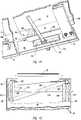
- FIG. 1is partial cutaway perspective view of a treadmill having an exemplary embodiment of a cushioning mechanism
- FIG. 2is a partial cross-sectional elevation view of the cushioning mechanism shown in FIG. 1 taken along section line 2 - 2 therein;
- FIG. 3is a partial cross-sectional elevation view of another exemplary embodiment of a cushioning mechanism
- FIG. 4is a partial cross-sectional elevation view of another exemplary embodiment of a cushioning mechanism
- FIG. 5is a partial cross-sectional elevation view of another exemplary embodiment of a cushioning mechanism
- FIGS. 6A-6Cfeature partial cross-sectional elevation views of another exemplary embodiment of a cushioning mechanism
- FIG. 7is a partial cutaway perspective view of a treadmill having another exemplary embodiment of a cushioning mechanism
- FIG. 8is a partial cross-sectional elevation view of the cushioning mechanism of FIG. 7 taken along section line 8 - 8 therein;
- FIG. 9is a partial cutaway top elevation view of another exemplary embodiment of a cushioning mechanism.
- FIG. 10is a partial cross-sectional elevation view of another exemplary embodiment of a cushioning mechanism
- FIG. 11is a partial cross-sectional perspective view of another exemplary embodiment of a cushioning mechanism
- FIG. 12is a partial cut-away top elevation view of another exemplary embodiment of a cushioning mechanism
- FIG. 13is a perspective view of a treadmill having another exemplary embodiment of a cushioning mechanism
- FIG. 14is a bottom view of a cushioning member of the treadmill featured in FIG. 13 shown adjacent a deck illustrated in a cutaway, exploded view;
- FIG. 15is a cutaway top view of the treadmill of FIG. 13 with first and second cushioning members of the cushioning mechanism shown partially in phantom views;
- FIG. 16 ais a top view of a cushioning member frame with cushioning pads shown in a cutaway view mounted therein.
- FIG. 16 bis a bottom view of the cushioning member frame of FIG. 17 a without the pads shown therein;
- FIG. 17is a cutaway top view of an alternate treadmill having the cushioning mechanism of FIG. 14 therein (shown partially in phantom lines) and having an aperture through the deck and side rail to thereby view a selected cushioning setting;
- FIG. 18is a bottom view of an alternate cushioning member with numbers indicating different cushioning portions shown in phantom lines;
- FIG. 19is a partially cutaway side view of an alternate treadmill having an aperture through the treadmill side rail and deck to thereby allow viewing of the number shown in phantom view in FIG. 18 ;
- FIG. 20illustrates another exemplary embodiment of a cushioning mechanism comprising a spring and a screw selectively mounted therein.
- the screwis shown in a cross sectional view
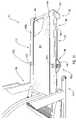
- FIG. 21illustrates another exemplary embodiment of a treadmill having a cushioning mechanism according to the present invention
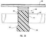
- FIG. 22illustrates a perspective close up view of a cushioning mechanism of FIG. 21 ;
- FIG. 23illustrates a cutaway view of the cushioning mechanism featured in FIG. 22 .
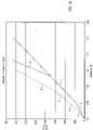
- FIG. 24illustrates a graphical representation of the deflection of the deck of the exercise device of FIG. 20 .
- the present inventionrelates to treadmills with an impact absorbing mechanism that is configured to selectively adjust the cushioning of a user's impact.
- FIG. 1Depicted in FIG. 1 is one embodiment of a treadmill that incorporates one or more the features of one embodiment of the present invention.
- the adjustable impact absorbing mechanism in the present inventionallows a user to select the amount of cushioning that will be provided by selectively adjusting the impact absorbing mechanism to individualize the amount of cushioning for a specific user as well as for a particular type of exercise.
- the adjustments made by a user to the impact absorbing mechanismare typically achieved without any disassembly of the treadmill.
- a treadmill 10includes an exercise base 12 and a support structure 14 .
- Support structure 14includes a handrail 16 that extends upwardly from exercise base 12 and means for supporting treadmill 10 upon a support surface such as a floor.
- One example of such meansis illustrated as feet 18 , which are located on both the right side of handrail 16 and on the left side of handrail 16 , wherein left and right are defined when a user is facing support structure 14 while standing on exercise base 12 .
- Handrail 16may include an optional control console 17 that is attached to the upper end of handrail 16 and extends laterally over exercise base 12 .
- Console 17may have an operating control such as an actuator switch to operate treadmill 10 and a means for indicating a status of the exercise device and/or the user operating the exercise device that may be operated by the user to determine various parameters associated with the exercise being performed.
- Console 17may also include a cup or glass holder so that the user may position liquid refreshment for use during the course of performing the exercise.
- console 17may only include on/off switch and therefore may be completely replaced by a lateral support member.
- Exercise base 12includes a front end 20 and a back end 22 . As illustrated in FIG. 1 , front end 20 of exercise base 12 is attached to support structure 14 and is rotatably attached to support structure 14 such that exercise base 12 may be rotated between an operational position, (illustrated in FIG. 1 ) and a storage position in which exercise base 12 is substantially vertical. Those skilled in the art will appreciate that various other methods of attaching exercise base 12 to support structure 14 may carry out the intended function thereof. In addition, there is no requirement that exercise base 12 be rotatable. It is contemplated that exercise base 12 may be fixedly attached to support structure 14 .
- exercise base 12includes a frame 24 that includes a right frame member 28 and a left frame member (not shown). In FIG. 1 , however, only the right side of treadmill 10 is visible. It is intended that the left side of frame 24 be a mirror image of the structure discussed relative to the right side.
- Right frame member 28 and left frame member (not shown)are in a spaced-apart, longitudinal relationship and are substantially parallel.
- Exercise base 12also includes a rear support member 30 that is attached to right frame member 28 and left frame member (not shown) at back end 22 of exercise base 12 .
- Exercise base 12includes a front roller 34 and a back roller 36 that are attached laterally near front end 20 and back end 22 of frame 24 , respectively.
- An endless belt 32is trained over front roller 34 and back roller 36 and is positioned between right frame member 28 and left frame member (not shown) so that belt 32 includes an upwardly exposed exercise section 38 upon which a user exercises.
- exercise base 12includes a deck 40 that is disposed between exercise section 38 of belt 32 and frame 24 .
- Deck 40is substantially rigid and provides a rigid support to a user exercising on exercise section 38 of belt 32 .
- deck 40is identified as being substantially rigid, one skilled in the art may appreciate that deck 40 may flex to some degree, to reduce the impact forces applied to a user's joints during exercise activities, such as, but not limited to, walking, running, jogging, and other similar related activities.
- Treadmill 10may also be used for stationary exercises such as stretching or bending while the user is standing on belt 32 .
- front end 20 and/or back end 22 of deck 40are not secured to the frame. Instead, end 20 and/or 22 move freely from frame 24 to permit a greater adjustment of cushioning.
- back end 22 of deck 40is secured to frame 24 (through the use of screws, or similar connectors), but the front end 20 of deck 40 is not secured to frame 24 .
- front end 20deflects freely from frame 24 to permit a greater adjustment of cushioning applied to front end 20 of deck 40 .
- both front end 20 and back end 22 of deck 40are secured to frame 24 and an adjustable cushioning is applied to the central portion of deck 40 between opposing ends 20 and 22 .
- the adjustable cushioningmay be applied in front and/or behind the points of securement of deck 40 to frame 24 .
- right frame member 28 and left frame memberincludes a side rail 42 and a side platform 44 .
- side platform 44is positioned over the top of side rail 42 of both right frame member 28 and left frame member (not shown).
- Side platforms 44are positioned on each side of belt 32 and are capable of supporting the weight of a user standing thereon.
- side platforms 44are such that a user of treadmill 10 may comfortably and easily step off of belt 32 onto one or both of side platforms 44 .
- a usermay also stand on side platform 44 on either side of exercise base 12 until he or she is ready to step onto belt 32 .
- frame 24that include right frame member 28 and left frame member (not shown) or the components thereof may carry out the intended function thereof.
- the present inventionincludes an impact absorbing mechanism 48 that is configured for manual adjustment to provide selectable amounts of impact cushioning when a user is operating on exercise section 38 of belt 32 .
- Impact absorbing mechanismwhich is an example of an impact absorbing means for providing selectable amounts of impact cushioning, allows the amount of cushioning provided by treadmill 10 to be manually adjusted to individualize treadmill 10 for different uses and/or users.
- FIGS. 1 and 2One embodiment of impact absorbing mechanism 48 is depicted in FIGS. 1 and 2 .
- impact absorbing mechanism 48includes a plurality of cushioning members 50 that are positioned between deck 40 and frame 24 .
- FIG. 1illustrates two (2) cushioning members 50 , it may be appreciated that various other numbers of cushioning members 50 may be used.
- Cushioning members 50are attached to opposing sides of frame 24 and are at least partially disposed between frame 24 and deck 40 .
- Cushioning members 50are substantially opposite to each other on frame 24 and are substantially perpendicular to deck 40 .
- Cushioning members 50include a plurality of portions having different cushioning properties.
- cushioning members 50are attached to the inside surface of frame 24 . It is contemplated, however, that cushioning members 50 may be attached to the outside surface of frame 24 and perform similar function to the embodiments described herein.
- Cushioning members 50include flexible bases 58 that include apertures 52 of varying sizes. As the size of aperture 52 increases, the stiffness of that portion of base 58 cushioning members 50 decreases. As a result, the size of aperture 52 in base 58 of cushioning members 50 is related to the flexibility provided by that portion of cushioning members 50 .
- the portions of cushioning member 50include different cushioning properties due to the varying size of the apertures to allow a user of treadmill 10 who may desire less cushioning, for example, to manually adjustably position cushioning members 50 so that the portion of cushioning members 50 with the smallest aperture 52 and, therefore, the least flexibility is proximate to deck 40 . In this position, cushioning members 50 have an increased stiffness that results in less cushioning. In contrast, when more cushioning is desired, cushioning members 50 are rotated to adjust cushioning members 50 so that a portion of bases 58 with progressively increasing sized apertures is against deck 40 to increase the flexibility and cushioning of cushioning members 50 .
- bases 48 of cushioning members 50are configured in a disk-like shape. While bases 58 , as shown, are substantially planar, it is not required that bases 58 be planar. Instead, bases 58 may have various other configurations such as elliptical, oval, octagonal, polygonal, or any other configuration so long as base provides various levels of flexibility and cushioning.
- the shape of bases 58is not particularly important since various other configurations of bases 58 may carry out the intended function thereof. What is important is that bases 58 of cushioning members 50 have portions of differing amounts of stiffness to correspondingly provide different amounts of cushioning in absorbing the impact between deck 40 and frame 24 when a user is operating on exercise section 38 of belt 32 .
- Cushioning members 50provide selectable amounts of impact cushioning.
- impact absorbing mechanism 48also includes means for selectively adjusting cushioning members 50 so as to selectively position one of the plurality of portions of cushioning members 50 between frame 24 and deck 38 .
- means for selectively adjusting cushioning members 50so as to selectively position one of the plurality of portions of cushioning members 50 between frame 24 and deck 38 .
- manually a usermay be able to physically move or rotate cushioning members 50 or press a button on console 17 to cause cushioning members 50 to be automatically and selectively adjusted to provide the desired amount of cushioning.
- handle 56is mounted outside frame 24 and is attached to one of cushioning members 50 .
- Handle 56is configured to cooperate with frame 24 .
- Other embodiments of handle 56perform the function thereof.
- handle 56may be a knob attached to base 58 of one of cushioning members 50 , particularly if cushioning members 50 are attached to the outside surface of frame 24 .
- Handle 56may be elongated, oval, round, square, polygonal, or may include various other geometric shapes. Handle 56 must just be something that the user may easily grasp.
- Other embodiments of handle 56may include some type of an elongated lever or rod.
- means for selectively adjusting cushioning members 50may include a button that is indexed to automatically and incrementally adjust cushioning members 50 to the specific amounts of cushioning.
- Other embodiments of means for selectively adjusting cushioning members 50may be a lever that is slidable on console 17 or a knob attached to console 17 that may be selectively rotated. The knob, the lever, or some other device may be moved on the console 17 by the user to position bases 58 of cushioning members 50 to corresponding positions to provide the selected amount of cushioning.
- Impact absorbing mechanism 48may optionally include means for mechanically interconnecting cushioning members 50 such that movement of one of cushioning members 50 results in corresponding movement of the other second cushioning members 50 and/or other cushioning members forming part of the exercise device.
- One embodiment of structure capable of performing the function of such a means for mechanically interconnecting a plurality of cushioning members 50includes an elongated axle 54 , as depicted in FIG. 1 .
- Axle 54is attached to cushioning members 50 and extends laterally therebetween.
- axle 54translates the movement to the remaining cushioning members 50 . Consequently, all of cushioning members 50 move substantially simultaneously to the selected position to provide the desired amount of cushioning.
- axle 54is substantially round.
- Axle 54could, however, have other embodiments such as a square, an oval, a rectangle, a polygon, or another shape.
- Various other configurations or embodiments of means for mechanically interconnecting first and second cushioning members 50 and optionally one or more other cushioning members,are capable of performing the function thereof.
- means for mechanically interconnecting cushioning members 50may include a linkage or a cable as will be discussed in further detail below.
- first and second cushioning members 50may each have a handle, such as handle 56 , attached thereto.
- This embodimentwould require a user to first make the adjustment to first cushioning member 50 located on one side of treadmill 10 and then move to the opposite side to manually adjust second cushioning member 50 or vice versa.
- the drawback with this embodimentis in that a user might forget to adjust cushioning members 50 on the opposite side or may inadvertently adjust only cushioning members 50 on one side of treadmill 10 resulting in cushioning members 50 having different settings.
- adjustable cushioning membersmay be provided along the length of the base 12 in order to provide a substantially horizontal deck 40 . It is also possible to employ both adjustable and non-adjustable cushioning members between frame 24 and deck 40 in order to provide a substantially horizontal deck 40 .
- FIG. 3depicts another embodiment of impact absorbing mechanism 66 .
- One of a plurality of cushioning members 68is shown in FIG. 3 .
- Impact absorbing mechanism 66includes a plurality of substantially identical cushioning members 68 that are movably attached to frame 24 and are substantially perpendicular to deck 40 .
- cushioning members 68each may be attached either inside or outside frame 24 .
- Cushioning members 68include a plurality of portions having different cushioning properties.
- Cushioning members 68each include a base 72 having a plurality of arms 70 projecting therefrom.
- base 72is substantially round.
- Base 72could, for example, alternatively be square, oval, elliptical, octagonal, triangular, polygonal, or another shape.
- Arms 70project radially from base 72 . While FIG. 3 illustrates that cushioning members 68 have four (4) arms 70 , it is contemplated that any number of arms 70 other than one (1) may be utilized. What is important is that the user may manually adjust cushioning members 68 to select between differing amounts of cushioning.
- Arms 70 of cushioning members 68are made of various materials with each having a different stiffness characteristic such that each of arms 70 experiences a differing amount of deflection when contacting deck 40 in response to a force from the impact of a user on exercise section 38 of belt 32 .
- arms 70may be substantially comprised of materials selected from the group consisting of plastic, hard rubber, soft rubber, and cellular foam. Various other kinds of materials that have differing stiffness characteristics may alternatively be used.
- arms 70may have other configurations such as being square, semispherical, half an ellipse, half an oval, polygonal, or a truncated cone and perform the desired function thereof.
- FIG. 4illustrates another embodiment of an impact absorbing mechanism 80 that includes cushioning members 82 .
- cushioning members 82are movably attached to frame 24 and may be disposed substantially perpendicular to deck 40 .
- Cushioning members 82include a plurality of portions having different cushioning properties.
- Cushioning members 82include a base 92 with arms 84 extending therefrom. In this embodiment, cushioning members 82 are substantially fan-shaped.
- cushioning members 82have arms 84 extending outwardly from base 92 .
- cushioning members 82have three (3) arms 84 .
- cushioning members 82could, however, have various other numbers of arms 84 .
- cushioning members 68 and 92 illustrated in FIGS. 3 and 4have arms 70 and 84 , respectively, that are parallel to bases 72 and 92 , respectively, arms 70 and 84 are not required to be parallel to bases 72 and 82 . Instead, bases 72 or 92 could be mounted on frame 24 so as to be substantially parallel with deck 40 . Arms 70 or 84 while extending outwardly from bases 72 or 92 now extend upward toward deck 40 . For example, arms 70 and 84 could be “L-shaped.” This embodiment of cushioning members performs the function thereof equally effectively.
- Impact absorbing mechanism 80includes an optional raised portion 86 on deck 40 that extends away from deck 40 toward frame 24 .
- Raised portion 86is configured to cooperate with arms 84 on cushioning members 82 .
- raised portion 86 of deck 40may be eliminated and arms 84 of cushioning members 82 may extend to directly contact deck 40 as in the embodiment illustrated in FIG. 3 .
- Impact absorbing mechanism 80 with cushioning members 82are somewhat similar to the embodiment of cushioning members 50 illustrated in FIG. 2 .
- arms 84 or base 92 of cushioning members 82have differently sized openings 88 formed therein and form a plurality of portions in cushioning members 82 having differing cushioning properties. Openings 88 are differently sized and, as a result, arms 84 each have differing amounts of stiffness. As shown, one of arms 84 of cushioning members 82 does not have an opening 88 that changes the stiffness of that arm 84 .
- each arm 84has a discrete and differing amount of flexibility and deflection in response to a user exercising on belt 32 as a result of the differing stiffness.
- Cushioning members 82consequently, will provide a differing amount of cushioning depending on which of arms 84 is in contact with deck 40 .
- Impact absorbing mechanism 80also includes an elongated lever 90 , as shown in phantom in FIG. 4 , configured to manually adjust cushion members 82 .
- Lever 90is one embodiment of structure capable of performing the function of means for selectively adjusting cushioning members 82 so as to selectively select one of the plurality of portions of cushioning members 82 between frame 24 and deck 40 .
- FIG. 5illustrates another embodiment of an impact absorbing mechanism 250 that includes cushioning members 252 .
- cushioning members 252are movably attached to frame 24 and are disposed substantially perpendicular to deck 40 .
- Cushioning members 252include a plurality of portions 258 having different cushioning properties.
- Cushioning members 252include a substantially fan-shaped base 254 having different flattened surfaces 255 extending around the rim 253 of base 254 .
- Base 254 of cushioning members 252has differently sized openings 256 formed therein, forming a plurality of portions 258 in cushioning members 252 having differing cushioning properties. Openings 256 are differently sized and as a result, different portions 258 of base 254 have differing stiffness. As shown, one of the portions 258 of cushioning members 252 does not have an opening 256 formed therein. This further changes the stiffness of that portion 258 . What is important is that each portion has discrete and differing amount of flexibility and deflection in response to a user exercising on belt 32 as a result of the differing stiffness. Cushioning members 252 , consequently, will provide a differing amount of cushioning depending on which portion contacts deck 40 .
- Impact absorbing mechanism 250also includes a hub 260 coupling base 254 to axle 54 .
- Hub 260includes fingers 262 (shown in phantom lines) extending radially from a hub sleeve 264 disposed about axle 54 and coupled to axle 54 through the use of a screw (not shown) disposed through sleeve 264 and axle 54 .
- base 254includes a flexible polyvinylchloride material that is molded onto a nylon or glass-filled nylon hub 260 .
- the polyvinylchloride materialmay have a durometer of about 65, shore A.
- impact absorbing mechanism 250is positioned toward front end 20 of base 12 , e.g., within the front one-third of base 12 . This positioning is particularly useful when front end 20 of deck 40 is not secured to frame 24 , e.g., when back end 22 of deck is secured to frame 24 (through the use of screws, for example), while front end 20 moves freely from frame 24 . Allowing front end 20 to freely deflect from frame 24 enhances the ability to adjust the amount of cushioning applied to deck 40 . In one such embodiment, front end 20 of deck 40 also rests on at least one additional cushioned member, such as an isolator coupled to each side of frame 24 , such as discussed below with reference to FIG. 11 .
- additional cushioned membersuch as an isolator coupled to each side of frame 24 , such as discussed below with reference to FIG. 11 .
- FIGS. 6A-6Cillustrate another embodiment of an impact absorbing mechanism 270 that includes cushioning members 272 .
- Cushioning members 272are movably attached to frame 24 and are disposed substantially perpendicular to deck 40 .
- Cushioning members 272include a plurality of portions having different cushioning properties.
- Each cushioning member 272includes a substantially fan-shaped base 274 having a plurality of recesses 275 extending around rim 273 of base 274 .
- Base 274 of cushioning member 272includes a flexible portion 277 attached through adhesion or molding to a substantially more rigid portion 276 , forming a plurality of portions in cushioning members 272 having differing cushioning properties. As a result, different portions of base 274 have differing stiffness. Cushioning members 272 , consequently, will provide a differing amount of cushioning depending on which portion contacts a wheel 288 pivotally coupled to deck 40 , as discussed below.
- Impact absorbing mechanism 270also includes a hub 280 coupling base 274 to axle 54 .
- Hub 280includes a hub sleeve 282 coupled to base 274 .
- hub sleeve 282is integrally coupled to member 276 and to a plate 271 , such that flexible portion 277 is cradled within plate 271 , hub 280 and member 276 .
- Hub sleeve 282is disposed about axle 54 and coupled to axle 54 using a screw (not shown) disposed through sleeve 282 and axle 54 , for example.
- flexible portion 277includes a flexible polyvinylchloride material that is molded onto a significantly more rigid nylon or glass-filled nylon member 276 and plate 271 .
- Hub 280may also include nylon or glass-filled nylon.
- the polyvinylchloride materialmay have a durometer of about 55, shore A.
- Impact absorbing mechanism 270further includes wheel 288 rotatably coupled to deck 40 .
- a bracket 290couples wheel 288 to deck 40 .
- Wheel 288is configured to mate with a selected recess 275 on cushioning member 272 .
- Wheel 288turns as cushioning member 272 turns. This assists in preserving the material of cushioning member 272 from damage as member 272 is turned. Stops 292 coupled to bracket 290 prevent the over-rotation of cushioning member 272 .
- axle 54includes a tab 294 coupled to axle 54 .
- a motorsuch as an extension motor, has an arm 293 pivotally coupled to tab 294 .
- the motorrotates axle 54 .
- the button and motor pivotally coupled to axle 54serve as another example of a structure capable of performing the function of means for selectively adjusting cushioning members 272 so as to select one of the plurality of portions of cushioning members 272 between frame 24 and deck 40 .
- impact absorbing mechanism 250is positioned toward front end 20 of base 12 , e.g., within the front one-third of base 12 .
- One or both of front and back ends 20 , 22 of deck 40may be secured to frame 24 .
- rigid portion 276includes a rim 269 having a T-shaped member 279 extending therefrom. Member 279 is covered by flexible portion 277 and enhances the adhesion of flexible portion 277 to the more rigid portion 276 .
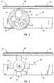
- FIGS. 7 and 8depict treadmill 10 with another embodiment of an impact absorbing mechanism 100 configured for manual adjustment to provide selectable amounts of impact cushioning when a user is operating on exercise section 38 of belt 32 .
- Impact absorbing mechanism 100includes cushioning members 102 .
- cushioning members 102are substantially parallel to deck 40 and are at least partially disposed between deck 40 and frame 24 .
- Cushioning members 102may be movably attached to either deck 40 or frame 24 .
- cushioning members 102are rotatably attached to deck 40 by a vertical axle 108 .
- Cushioning members 102 illustrated in FIGS. 7 and 8have substantially the same configuration as cushioning members 50 depicted in FIGS. 1 and 2 .
- Cushioning members 102include a plurality of portions having different cushioning properties.
- Cushioning members 102include a base 112 with a plurality of openings 52 formed therein. Bases 112 of cushioning members 102 are shown as round, but it is intended, particularly in this embodiment, that cushioning members 102 may have various other shapes without effecting the function thereof.
- Cushioning members 102may be square, rectangular, polygonal, oval, or various other configurations.
- treadmill 10has a knob 110 on console 117 that causes cushioning members 102 to be selectively adjusted according to the desired amount of cushioning.
- Knob 110 on console 117is one embodiment of structure capable of performing the function of a means for selectively adjusting cushioning members to provide differing amount of impact cushioning.
- Various other embodiments of structure capable of performing the function of such a means for selectively adjusting cushioning membersare known to those skilled in the art in light of the teaching contained herein, including, but not limited to, those disclosed with respect to other embodiments of cushioning members.
- Impact absorbing mechanism 100also includes a linkage or a cable 106 , shown in FIG. 7 , configured to mechanically interconnect cushioning members 102 such that movement of one cushioning member 102 results in corresponding movement of other cushioning members 102 .
- a linkage or a cable 106shown in FIG. 7
- mechanically interconnect cushioning members 102such that movement of one cushioning member 102 results in corresponding movement of other cushioning members 102 .
- Various embodiments of structure capable of performing the function of such means for mechanically interconnecting cushioning members 102are known to those skilled in the art in light of the teaching contained herein.
- horizontal axle 54may be mechanically interconnected with vertical axles 108 of cushioning members 102 such that movement of one of cushioning members 102 results in corresponding movement of other cushioning members 102 .
- bases 112 of cushioning members 102are depicted as having variously sized openings 52 , other embodiments of cushioning members 102 perform the desired function thereof.
- raised padscomprising materials with different cushioning properties may be mounted on cushioning members 102 .
- Cushioning members 102may be selectively adjusted such that the raised pads mounted on cushioning members 102 are selectively positioned on raised portion 104 .
- cushioning members 102may be movably attached to frame 24 by vertical axles.
- Impact absorbing mechanism 120includes cushioning members 122 attached to opposite sides of frame 24 .
- Cushioning members 122are elongated and in the embodiment shown in FIG. 9 are substantially curved.
- cushioning members 122may be rectangular, square, polygonal, semispherical, half an oval, half-an-ellipse, or semicircular.
- cushioning members 122include bases 30 that have a plurality of raised pads 124 mounted thereon. Raised pads 124 each include a material with different cushioning properties.
- the arrangement of raised pads 124 on cushioning members 122 a on one side of the exercise deviceis in an inverse mirror image configuration with respect to cushioning members 122 b on the opposite side of frame 24 , as will be discussed in more detail below.
- Impact absorbing mechanisms 120also include an elongated beam 126 movably mounted below deck 40 .
- Beam 126extends across frame 24 and is substantially parallel to deck 40 .
- a portion of beam 126is disposed between deck 40 and cushioning members 122 to contact the various raised pads 124 .
- Beam 126is pivotally connected to deck 40 .
- Raised pads 124are arranged on cushioning members 122 , or 122 a and 122 b , so that beam 126 is pivoted to contact one type of raised pad 124 on cushioning members 122 and an opposite end of beam 126 contacts the same material on the opposite of cushioning members 122 , as illustrated in FIG. 9 .
- Beam 126is another embodiment of structure capable of performing the function of such means for mechanically interconnecting the plurality of cushioning members 122 .
- Beam 126has an elongated handle 128 attached to one end thereof for the user to grasp to selectively, manually adjust the amount of cushioning provided by cushioning members 122 .
- a user of treadmill 10may move beam 126 by moving handle 128 until beam 126 contacts the selected raised pads 124 to obtain differing amounts of cushioning of the impact.
- FIG. 9illustrates in phantom an example of another position of beam 126 for a differing amount of cushioning.
- Handle 128extends away from beam 126 above frame 24 .
- Handle 128is one example of structure capable of performing the function of means for selectively positioning one of the plurality of portions of cushioning members.
- the cushioning members described hereinare exemplary embodiments of structures capable of performing the function of means for selectively adjusting the cushioning impact between deck 40 and frame 24 .
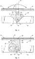
- FIG. 10illustrates another embodiment of impact absorbing mechanism 140 that includes a plurality of flexible cantilevers 142 .
- Cantilevers 142include a support 144 attached to the inside surface of frame 24 and extends in a direction away from frame 24 .
- Cantilevers 142include an elongated flexible arm 146 that is attached at one end to support 144 . Arm 146 extends toward front end 20 of frame 24 . Arm 146 has an opposite end that is freely disposed from support 144 and frame 24 .
- Cantilevers 142also include a bumper 148 mounted on the free end of arm 146 . Bumper 148 extends away from free end of arm 146 toward deck 40 in a direction that is substantially perpendicular to deck 140 .
- frame 24 ahas elongated slots 152 formed therein to accommodate movement of brace 150 , which is selectively movable along the longitudinal axis of frame 24 and the length of cantilever 142 to change in the amount of cushioning provided by cantilevers 142 by increasing or decreasing the amount of deflection of arm 146 in response to a user operating on the exercise section 38 of belt 32 .
- brace 150is moved along the length of cantilevers 142 towards bumper 148 on arm 146 , the amount of deflection or amount of cushioning is decreased.
- the amount of deflectionwill increase which consequently results in the amount of cushioning provided to the user increasing.
- brace 150 and slots 152may perform the function thereof as long as brace 150 and slots 152 are configured to cooperate.
- Brace 150 and slots 152 in frame 24are one example of structure capable of performing the function of a means for selectively adjusting the flexibility of cantilever 142 .
- FIG. 11illustrates yet another embodiment of an impact absorbing mechanism 160 that includes a plurality of flexible cantilevers 162 , only one of which is shown in FIG. 11 .
- Cantilever 162includes a support 164 attached to an inside surface of frame 24 , such as a crossbeam.
- Cantilever 162further includes an elongated arm 166 , such as, but not limited to, steel or other metal arm that is attached at one end to support 164 .
- Arm 166extends toward front end 20 of frame 24 .
- Arm 166has an opposite end that is freely disposed from support 164 and frame 24 .
- Cantilever 162also includes a bumper 168 mounted on the free end of arm 166 .
- Bumper 168extends away from the free end of arm 166 toward deck 40 in a direction that is substantially perpendicular to deck 40 .
- another elongated arm and a bumper attached theretoextends from an a opposing end of support 164 in parallel relationship to cantilever 162 shown in FIG. 11 .
- bumper 168is positioned toward the front end 20 of base 12 , e.g., within the front one-third of base 12 .
- Impact absorbing mechanism 160further includes an elongated brace 170 that is configured to manually adjust the flexibility of cantilevers 162 .
- Brace 170is mounted to frame 24 adjacent to cantilevers 162 .
- Brace 170extends substantially perpendicular to the longitudinal axis of frame 24 and is configured to cooperate with frame 24 and to move parallel to the longitudinal axis of frame 24 .
- frame 24has elongated slots 172 formed therein to accommodate movement of brace 170 .
- a second slotis not shown in FIG. 11 , but is preferably on an opposing side of frame 24 from slot 172 for receiving an opposing end of brace 170 from that shown in FIG. 11 .
- Brace 170is selectively movable along the longitudinal axis of frame 24 within opposing slots 172 and along the length of opposing cantilevers 162 to change the amount of cushioning provided by cantilevers 162 by increasing or decreasing the amount of deflection of arms 166 in response to a user operating on the exercise section 38 of belt 32 .
- brace 170For example, if brace 170 is moved along the length of cantilever 162 towards bumper 168 on arm 166 , the amount of deflection or amount of cushioning is decreased. In contrast, if brace 170 is moved towards support 164 , the amount-of deflection will increase which consequently results in the amount of cushioning provided to the user increasing.
- each of the opposing slots 172have teeth 174 therein for selectively receiving gears 176 coupled to opposing ends of brace 170 .
- Teeth 174 and gears 176allow convenient adjustment of brace 170 within slots 172 and assist in maintaining brace 170 in a desired orientation within slots 172 during an exercise routine.
- each of the opposing cantilevers 162is adjusted, preferably achieving an equal degree of deflection.
- brace 170 and slots 172may perform the desired function as long as brace 170 and slots 172 are configured to cooperate.
- Brace 170 and slots 172 in frame 24are one example of structure capable of performing the function of a means for selectively adjusting the flexibility of one or more cantilevers.
- front end 20 of deck 40is not secured to frame 24 .
- back end 22 of deck 40is secured to frame 24 (through the use of screws, for example), while front end 20 moves freely from frame 24 , enhancing the ability to adjust the amount of cushioning applied to front end 20 of deck 40 .
- At least one and preferably both sides of front end 20 of deck 40also rest on a cushioned isolator 180 , shown in FIG. 11 , without being coupled to the isolator 180 .
- front end 20 and back end 22 of deck 40are both coupled to frame 24 by screws, for example.
- the screwsmay be disposed through the deck, the frame, and an isolator, such as isolator 180 disposed between the frame and the deck, for example.
- FIG. 12Another example of an impact absorbing mechanism 200 that includes a plurality of flexible cantilevers 202 , 204 is shown in FIG. 12 .
- Cantilevers 202 , 204include a support 205 attached to frame 24 diagonally with respect to the longitudinal axis of frame 24 .
- Cantilevers 202 , 204further include respective elongated arms 206 , 208 attached to opposing ends of diagonal support 205 .
- Bumpers 207 , 209are coupled to free ends of respective arms 206 , 208 below deck 40 .
- Bumpers 207 , 209extend upwardly with respect to respective arms 206 , 208 and intersect deck 40 .
- bumpers 207 , 209 and arms 206 , 208 of respective cantilevers 202 , 204are oriented in opposing directions.
- Impact absorbing mechanism 200further includes an elongated brace 210 that is configured to manually adjust the flexibility of cantilevers 202 , 204 .
- Brace 210is mounted to frame 24 by being pivotally coupled to support 205 .
- Brace 210has opposing ends that are disposed beneath respective arms 206 , 208 .
- Frame 24has elongated slots 212 , 214 formed therein on opposing sides to accommodate pivotal movement of the ends of brace 210 .
- Brace 210moves along the length of opposing cantilevers 202 , 204 to change the amount of cushioning provided by cantilevers 202 , 204 by increasing or decreasing the amount of deflection of arms 202 , 204 .
- One advantage of mechanism 200is that the amount of cushioning provided is adjustable by pivoting brace 210 in a desired direction.
- Brace 210 and slots 212 , 214 in frame 24are one example of structure capable of performing the function of means for selectively adjusting the flexibility of one or more cantilevers.
- treadmill 10includes means for supplying power to exercise base 12 to drive continuous belt 32 .
- the means for supplying power to base frame 12is disposed in front end 20 of exercise base 12 .
- One embodiment of structure capable of performing the function of such a meansincludes a motor that rotates a first pulley and drives a belt.
- the beltdrives a second pulley that is connected to front roller 34 about which belt 32 is disposed.
- the rear portion of belt 32is also disposed around rear roller 36 .
- Other embodiments capable of performing the function of such a meansmay include a flywheel.
- the flywheelis connected to belt 32 and receives energy from the user operating on belt 32 of exercise base 12 .
- the flywheelalso delivers energy to belt 32 as the user performs walking, running or jogging exercises when a user is not in contact with belt 32 .
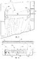
- FIGS. 13-16Bdepict an alternate treadmill 310 with another embodiment of an impact absorbing mechanism 300 that is configured for selective adjustment to provide selectable amounts of impact cushioning when a user is operating on an exercise section of a belt.
- Treadmill 310includes an exercise base 304 including: (i) a frame 324 , which may be the same or similar to the frame 24 of FIGS. 1 and 7 ; (ii) an endless belt 332 trained about front and rear rollers coupled between opposing ends of right and left frame members 325 , 326 ( FIG. 15 ), such as discussed regarding belt 38 of FIGS. 1 and 7 ; (iii) a deck 340 ( FIGS. 14-15 ) coupled to frame 324 , such as discussed regarding deck 40 of FIGS. 1 and 7 ; and (iv) an impact absorbing mechanism 300 at least partially disposed between deck 340 and frame 324 .
- a support structure 306is coupled to base 304 (e.g., rotatably coupled to the base 304 such that the base 304 may be selectively oriented in an operational position, as shown in FIG. 13 , or an upright storage position).
- Impact absorbing mechanism 300which is another example of an impact absorbing means, includes first and second cushioning members 302 ( FIGS. 14-15 ) on opposing sides of treadmill 310 .
- Cushioning members 302are optionally substantially parallel to deck 340 and are at least partially disposed between deck 340 and frame 324 . While cushioning members 302 may be movably attached to either deck 340 or frame 324 , in the embodiment of FIG. 14 cushioning members 302 are rotatably attached to deck 340 by a vertical axle 308 , such that frame 324 of treadmill is contacted by downwardly extending cushioning members 302 .
- Member 302has a plurality of portions, each of which have different cushioning properties, as will be discussed in detail below. To adjust the degree of cushioning, the user causes at least one and preferably both cushioning members 302 to rotate horizontally such that the desired cushioning portion is positioned between the treadmill deck 340 and frame 324 .
- cushioning members 302each include a base 312 with a plurality of arms 302 a - 302 c projecting therefrom. Arms 302 a - 302 c , each have different cushioning properties. Thus, cushioning members 302 each have a plurality of cushioning portions, namely arms 302 a - 302 c , each having different cushioning properties. Members 302 each have a generally triangular shape. However, it is intended that the cushioning members that rotate horizontally to adjust the degree of cushioning may have various other shapes without affecting the function thereof, such as square, rectangular, polygonal, oval, propeller-shaped, or various other configurations.
- a spring loaded ball detent 318engages one of three recessed areas 320 a - 302 c ( FIG. 15 ) on the top surface of cushioning member 302 , depending upon the degree of cushioning selected by the user.
- the recessed areas 320 a - 320 care positioned so as to selectively engage the detent 318 and thereby hold the desired respective arm 302 a - 302 c in place between deck 340 and frame 324 .
- the same resultmay be achieved by placing a detent in cushioning member 302 which could engage one of a number of different recessed areas in deck 340 or frame 324 .
- the detentmay be molded as part of cushioning member 302 .
- Differing degrees of cushioningmay be achieved in cushioning members 302 by (i) providing cushioning portions of differing materials; (ii) providing cushioning portions having differing levels of flexibility; (iii) providing cushioning portions having different sizes and/or (iv) providing cushioning portions that are hollower than others, for example.
- a variety of different methods of manufacturemay be employed to form each member 302 .
- each member 302is formed by forming a frame 314 configured to hold a plurality of cushioning pads 316 a - 316 c therein.
- Each arm portion 302 a - 302 cincludes (i) a respective frame portion 317 a - 317 c ; and (ii) a respective pad 31 . 6 a - 316 c coupled to a respective frame portion 317 a - 317 c.
- frame 314includes a rigid or semi-rigid material, while cushioning pads 316 a - 316 c each include a more flexible material that is coupled onto frame 314 , such as, but not limited to, through molding.
- frame 314may include a material that is more rigid than pads 316 a - c for example.
- frame 314is molded, after which pads 316 a - 316 c are molded thereon.
- the frame and/or pad portions of cushioning members 302may be formed from SANTOPRENE, polyvinyl chloride (PVC), thermoplastic elastomer, foam and/or other suitable material.
- the frame 314 and pads 316 a - ceach include a SANTOPRENE material, but have different degrees of flexibility.
- Frame 314is configured to receive different pads therein, the pads being shown in a bottom view in FIG. 14 , and in a cutaway top view in FIG. 16A .
- a bottom view of the frameis shown without the pads in FIG. 16B .
- cushioning frame 314includes a first frame portion 317 a , a second frame portion 317 b , and a third frame portion 317 c .
- First and second frame portions 317 a - 317 bessentially have large apertures therethrough, such that a significant amount of space is available for corresponding pad material 316 a - 316 b .
- Third frame portion 317 cincludes more frame material and has less space therein for the corresponding pad material 316 c.
- arm 302 csince arm 302 c includes a substantial amount of rigid or semi-rigid frame material 317 c and a reduced amount of flexible pad material 316 c , arm 302 c is more rigid than arms 302 a and 302 b .
- the pad material 316 a of arm 302 ahas a large groove therein, whereas the pad material 316 b of arm 302 b is solid.
- arm 302 ais more flexible than arm 302 b.
- arm 302 cincludes less pad material 316 c and more frame material 317 c than arm 302 b , and is consequently more rigid than arm 302 b .
- Arm 302 ahas a pad 316 a having a substantial groove therein, and is consequently more flexible than arm 302 b .
- arm 302 cis more rigid than arm 302 b , which is more rigid than arm 302 a .
- a user desiring different cushioning properties for treadmill 310may select a desired level of cushioning.
- arms 302 a - 302 c of cushioning members 302are depicted as having raised pad portions formed thereon that have different internal configurations, other embodiments of cushioning members perform the function thereof, such as by employing pad portions having different sizes or different densities.
- cushioning members 302may be pivotally mounted below deck 340 , cushioning members 302 may be movably attached to frame 324 by vertical axles.
- Indiciasuch as the numbers 1, 2, and 3 (or other indicia, such as lettering, color coding, providing other symbols, etc.) may be provided on the frame and/or pads of member 302 to allow a user to visually determine which amount of cushioning has been selected.
- the numeral “ 1 ”corresponds to the most flexible amount of cushioning (arm 302 a )
- the numeral “ 2 ”corresponds to an intermediate amount of flexibility (arm 302 b )
- the numeral “ 3 ”corresponds to the most rigid amount of cushioning (arm 302 c ).
- a user desiring an intermediate level of cushioningmay move cushioning members 302 until the number 2 or other indicia appears on the edge of the treadmill of FIG. 15 .
- arms 302 b of members 302are mounted between frame 324 and deck 340 to thereby provide an intermediate level of flexibility to treadmill 310 .
- Gripping grooves 322 on members 302allow a user to conveniently grip member 302 .
- members 302may be selectively adjusted according to the desired amount of cushioning by gripping the gripping grooves 322 and rotating member 302 in a horizontal plane.
- Such grooves 322are one embodiment of structure capable of performing the function of a means for selectively adjusting cushioning members 302 to provide differing amounts of impact cushioning.
- Various other embodiments of structure capable of performing the function of such a means for selectively adjusting members 302may be employed.
- Impact absorbing mechanism 300may further include a linkage or a cable (not shown), (e.g., similar to element 106 shown in FIG. 7 ), configured to mechanically interconnect cushioning members 302 such that movement of one cushioning member 302 results in corresponding movement of other cushioning members 302 .
- a linkage or a cable(not shown), (e.g., similar to element 106 shown in FIG. 7 ), configured to mechanically interconnect cushioning members 302 such that movement of one cushioning member 302 results in corresponding movement of other cushioning members 302 .
- a linkage or a cable(not shown), (e.g., similar to element 106 shown in FIG. 7 ), configured to mechanically interconnect cushioning members 302 such that movement of one cushioning member 302 results in corresponding movement of other cushioning members 302 .
- frame 324includes right and left frame members 325 , 326 , such as discussed with reference to base 12 of FIG. 1 .
- Front and back rollersare attached laterally between respective front and back ends of frame members 325 , 326 and an endless belt 332 is trained over the front and back rollers.
- a right side rail 342is shown mounted on deck 340 .
- a left side railmay also be mounted on deck 340 .
- Deck 340may be mounted on frame 324 in a variety of different manners, such as those discussed above with regard to deck 40 and frame 24 .
- the rear portion of the deckis immovably affixed to rear portions of opposing frame members 325 , 326 while the front portion of the deck 340 is coupled to the front portions of opposing frame members 325 , 326 through the use of elastomeric isolators coupled between the deck and the frame that allow some deflection between the deck 340 and the frame 324 during use.
- both the rear portion and the front portion of the deckare coupled to opposing frame members 325 , 326 through use of elastomeric isolates.
- the front portion of deck 340is affixed to the front portion of opposing frame members 325 , and 326 .
- FIG. 17provides a view of an alternate treadmill embodiment of the present invention, wherein first and second frame members 324 a (only one frame member shown) are positioned below deck 340 a in such as manner that the frame members 324 a are inwardly disposed with respect to the sides of deck 340 a .
- the indiciae.g., the numeral “2”
- a corresponding aperture 341also exists in the side deck rails 342 a , which are mounted on the sides of deck 340 a adjacent treadmill belt 338 a .
- deck 340 a and side deck rail 342 a of the present inventioneach have an aperture 341 therethrough such that the user may see through deck 340 a and rail 342 a to view the indicia (e.g., the numeral “2”) on respective members 302 on opposing sides of the deck 340 a .
- One or both sides of deck 340 a and one or both corresponding deck railsmay have an aperture 341 therethrough corresponding to one or more respective cushioning members 302 .
- FIG. 18provides a top view of an alternate cushioning member 350 of FIG. 17 .
- the cushioning member 350includes a base 351 having a plurality of arms 352 a - 352 c radially extending therefrom.
- Each of the cushioning arms 352 a - 352 chas different cushioning properties to allow a user to selectively adjust the amount of cushioning provided.
- the difference in cushioningmay be achieved using material having different densities, different configurations, different sizes, by hollowing on or more portions, or using stiffer materials surrounded by different amounts of padded material, for example.
- arm 352 bis denser, and consequently more stiff, than arm 352 a and less dense and stiff than arm 352 c .
- the pad on an intermediate level cushioning armis larger than the least cushioned arm and smaller than the most cushioned arm.
- an arm having a hollow or grooved pad, an arm having a solid pad, and an arm comprising more frame material than the other arms, as discussed with reference to member 302are employed.
- Indicia, e.g., numerals corresponding to the differences in flexibilityare shown in phantom lines. These indicia appear on the top portions of arms 352 a - 352 c.
- an example of another cushioning mechanism of the present inventionincludes first and second cushioning members, configured such as member 350 , on opposing sides of a treadmill between the deck and the frame thereof.
- member 350may be employed on a single side to form a cushioning mechanism.
- cushioning member 350is coupled between frame 324 a and deck 340 a , such as with a vertical axle.
- Deck rail 342is also shown.
- deck rail 342 and deck 340 aeach have an aperture 341 therethrough that allows the user to visually inspect the corresponding indicia, e.g., numeral, to thereby determine the amount of cushioning selected by the user.
- the deck rail 342 of FIG. 19has an integral tubular sleeve 358 that fits downwardly within the aperture in deck 340 a to thereby enhance the aesthetic appearance of the aperture in deck 340 a . By viewing through sleeve 358 , the user may see what level of cushioning has been selected.
- a glass or plastic windowmay be placed in the aperture in the deck and/or rail.
- the deck rail(s) 342 a discussed with respect to FIG. 17may optionally employ sleeve 358 shown in FIG. 19 .
- the cushioning portions with the indicia thereonmay extend out from the area directly between deck and the frame such that the indicia is visible to the user, or an aperture through the deck may be employed.
- an aperture through the deckmay be employed.
- FIG. 20depicts an alternate embodiment of an adjustable cushioning mechanism 400 for use in an exercise device, such as a treadmill.
- Cushioning mechanism 400includes a spring 402 and a screw 404 threadably mounted within spring 402 .
- Spring 402is coupled between treadmill deck 406 and treadmill frame 408 .
- An aperture 412extends through frame 408 (or optionally, in another embodiment, through the deck) and receives screw 404 therethrough.
- the interior of spring 402is configured to correspond to threads 410 of screw 404 and to allow screw 404 to be threaded therethrough in a helical fashion.
- treadmill frame 408is raised off the support surface sufficiently enough that the user may place his/her hand under frame 408 , grip a knob 414 of screw 404 , and selectively thread screw 404 into spring 402 or out of spring 402 to thereby adjust the amount of flexibility achieved.
- the space between the support surface and knob 414allows the user to rotate knob 414 .
- screw 404is coupled to an adjustment mechanism that includes a motor to selectively adjust the cushioning by threading the screw.
- Spring 402may be coupled between deck 406 and frame 408 in a variety of different manners.
- the ends of the deck and the frameare coupled together in such a manner as to maintain spring 402 therebetween.
- one or both ends of the springare embedded into a corresponding deck or frame portion.
- one end (e.g., the top end) of the springmay be embedded in the deck or frame while the opposing portion of the spring is not embedded but rests against the opposing frame or deck portion.
- a screwextends from the deck or frame (or both) and connects with the corresponding end (e.g., the top end) of the spring.
- the opposing ends of the springare captured within cups (i.e., surrounded by the rims of the cups) mounted on respective portions of the deck and frame.
- One or both cupsmay have an aperture therethrough in order to allow the screw to extend therethrough.
- frame 408is internally threaded so as to threadably receive screw 404 therein.
- screw 404is threadably received within frame 408 and spring 402 .
- screw 404may include an elastomeric, plastic, synthetic, or similar material, although a variety of different materials may be employed.
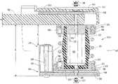
- FIGS. 21-23depict another embodiment of the present invention.
- An exercise device 510such as a treadmill, includes an exercise base 512 and a support structure 514 , in a similar manner to treadmill 10 of FIG. 1 .
- the exercise base 512includes a front end 520 and a back end 522 . Front end 520 of exercise base 512 is attached to support structure 514 .
- base 512is rotatably attached to support structure 514 such that base 512 can be readily folded into a storage position.
- optionally exercise base 512may be fixably attached to support structure 514 .
- Exercise base 512additionally includes a frame 524 that has a left frame member 528 and a right frame member (not shown), however, only the left side of exercise device 510 is visible. As with treadmill 10 of FIG. 1 , it is intended that the right side of frame 524 be mirror image of the structure discussed relative to the left side. Left frame member 528 and right frame member (not shown) are in spaced-apart, longitudinal relationship. Exercise base 512 also includes a rear support member 530 that is attached to left frame member 528 and right frame member (not shown) at backend 522 of exercise base 512 .
- the absorbing assembly 548may be linked or coupled, either directly or indirectly, to frame 524 and deck 540 and provides cushioning to a user exercising upon deck 540 . Portions of absorbing assembly 548 are removable and/or replaceable to allow a user to vary the cushioning effect provided to the exercising user.
- the absorbing assembly 548allows deck 540 to move towards frame 524 , and more generally toward a surface upon which exercise device 510 rests, a sufficient distance to cushion the motion of the exercising user.
- the absorbing assembly 548limits the potential for user injury through absorbing assembly 548 reducing the force applied by deck 540 to the user as he or she runs, jogs, walks, or generally exercises using exercise device 510 .
- deck 540is movable as the user places his or he foot thereupon. The delay between placing of the foot upon deck 540 and deck 540 stopping its motion towards frame 524 provides cushioning to the exercising user that limits the potential for user injury. The amount of distance traveled and the time taken to travel such a distance reduces the application of a substantially immediate impact force upon the legs of the user as he or she exercises upon the exercise device. The graduated application of the impact force reduces the intensity of the force and reduces the potential for user injury.
- the degree of displacement or movement of deck 540may be controlled by the configuration of absorbing assembly 548 and optionally the flexibility of deck 540 .
- FIG. 21positioned over the top of deck 540 is an endless belt 532 upon which the user exercises.
- a fastenersuch as a bolt, screw, or other structure that connects a portion of absorbing assembly 548 to deck 540 .
- Impact absorbing assembly 548 of exercise device 510is disposed beneath a side of deck 540 and is configured to cushion impact forces applied by a user of exercise device 510 upon deck 540 .
- the cushioning provided by impact absorbing assembly 548may be adjusted to provide selectable amounts of impact cushioning when a user is operating on deck 540 and/or belt 532 . This adjustability enables a user to individualize exercise device 510 for different uses and/or users.
- Impact absorbing assembly 548is one structure capable of performing the function of means for cushioning impact upon deck 540 .
- Other configurations of impact absorbing assembly 548 and hence means for cushioningmay have an impact absorbing assembly located to the side of deck 540 or at least partially disposed to a side of and beneath deck 540 .
- the impact absorbing assembly 548 associated with exercise device 510may include individual absorbing mechanisms 550 a and 550 b , which are disposed on opposite sides of frame 524 by way of platform 556 and may extend from deck 540 toward frame 524 .
- impact absorbing assembly 548being located at a side of frame 524 , while being disposed beneath deck 540 , other configurations of the present invention may include absorbing mechanisms that are at least partially disposed between frame 524 and deck 540 and/or extend from deck 540 to a position lower than a portion of frame 524 .
- absorbing mechanisms 550 a and 550 bare depicted as being attached to an outside surface of frame 524 , it is contemplated, that absorbing mechanisms 550 a and 550 b may optionally be attached to the inside surface of frame 524 and perform the desired functions thereof.
- absorbing assembly 548includes one or more absorbing mechanisms and one or more platforms.
- Absorbing mechanism 550 bis mounted to frame 524 by way of a platform 556 that supports absorbing mechanism 550 b and positions absorbing mechanism 550 b a distance from a side of frame 524 .
- the absorbing mechanism 550 bincludes, in one embodiment, a first cushioning member 552 , a second cushioning member 554 , such as, but not limited to, one or more springs, cooperating with cushioning member 552 , and cups 560 and 562 coupled to deck 540 and platform 556 ; cups 560 and 562 maintaining cushioning member 552 relative to second cushioning member 554 .
- the means for cushioningmay include (i) cushioning member 550 b with or without second cushioning member 554 or (ii) second cushioning member 554 with or without first cushioning member 550 b .
- the absorbing mechanism and the means for cushioningmay include platform 556 .
- Platform 556may be attached to frame 524 through use of one or more fasteners 558 , such as screws, bolts, or other structures that are capable of attaching platform 556 to frame 524 .
- platform 556may be rigidly attached or linked to frame 524 .
- platform 556may be attached or linked in a flexible manner to frame 524 .
- the platform 556is configured to attach to a lower portion 557 of frame 524 , extend from frame 524 , and cooperate with absorbing mechanism 550 b .
- the platform 556may alternatively be attached to frame 524 in any manner so long as the platform 556 enables absorbing mechanism 550 b to at least partially be disposed lower than upper portion 559 of frame 524 .
- a platformmay attach to upper portion 559 or any position between upper portion 559 and lower portion 557 of frame 524 while extending from frame 524 in a manner that positions one end of the absorbing mechanism lower than upper portion 559 of frame 524 .
- the first cushioning member 552 of absorbing mechanism 550 bcooperates with platform 556 by way of second cup 562 and a fastener 577 , such as a screw, bolt, or other structure capable of connecting cushioning member 552 to platform 556 .
- First cushioning member 552has a generally cylindrical or barrel shape with a hollow interior 551 .
- a first end 553 of first cushioning member 552cooperates with first cup 560
- a second end 555cooperates with second cup 560 .
- the hollow interior 551allows the sides of first cushioning member 552 to move outwardly from a central axis of first cushioning member 552 as first end 553 moves toward second end 555 .
- caps 560 and 562retain first cushioning member 552 and second cushioning member 554 prevents overextension of the sides of cushioning member 552 .
- a portion of absorbing mechanism 550 b and hence first cushioning member 552 and/or second cushioning member 554may be positioned lower than an upper portion 559 of frame 524 so that the length of absorbing mechanism 550 b may be longer than the distance between the lower surface of deck 540 and upper portion 559 of frame 540 .
- Positioning absorbing mechanism 550 b to the side of frame 524 with a portion of absorbing mechanism 550 b lower than upper portion 559 of frame 524allows deck 540 to be moved toward upper portion 559 and the surface upon which exercise device 510 rest to a greater degree than would be possible if absorbing mechanism 550 b were disposed between upper portion 559 and deck 540 .
- deck 540is separated from a surface upon which exercise device 510 rests by a distance D 1 .
- the deck 540is also separated from upper portion 559 of frame 524 by a distance D 2 .
- Distances D 1 and D 2change as a user exercises deck 540 .
- Distances D 1 and D 2are lessened as the user exercises.
- absorbing assembly 548enables distances D 1 and D 2 to be changed more than about 1 inch upon a force being applied to deck 540 .
- Exercise device 510therefore, allows deck 540 to move toward the surface upon which the exercise device 510 rests or toward upper portion 559 of frame 524 up to and more than about 1 inch.
- the same deviceenables deck 540 to move toward the surface upon which the exercise device 510 rests or upper portion 559 of frame 524 a distance more than about 1 inch for a variety of different forces applied to deck 540 .
- the forcesmay range from about 0 lbs to about 1400 lbs resulting in changes in distances D 1 and D 2 in the range of about 0 inches to greater than about 2 inches.
- the change in distances D 1 and D 2may be different.
- distances D 1 and D 2may be changed up to and more than about 1 inch, 1.25 inches, 1.5 inches, 1.75 inches, 2.0 inches, 2.25 inches, or 2.5 inches upon a variety of different force being applied to deck 540 as an exercising user impacts upon deck 540 .
- distances D 1 and D 2may be changed up to and more than about 1.25 inches upon application of 600 lbs of force to deck 540 by an exercising user impacting upon deck 540 .
- illustrative D 1 and D 2 valuesmay by identified, as illustrated in FIG. 24 .
- FIG. 24has along its X-axis values representing the deflections of the deck 50 in inches and, along the Y-axis, corresponding impact force values in pounds. These impact force values may be derived by calculating the force required to compress the absorbing mechanism 550 b . Alternatively, these force/deflection values may be determined empirically.
- the deflection distancemay be greater than the illustrated curve for a force lesser than those indicated by the lines.
- the deflection distancemay have any value defined by the area or region of the graph below the lines illustrated in FIG. 24 and above the X-axis.
- the differently sized cushioning membersprovide differing cushioning characteristics, such as extra large cushioning members that provide maximum cushioning without raising the overall height of the exercise device. This system efficiently enables increased cushioning, without increasing deck height, thereby making the exercise device more convenient to use and store.
- Increasing the available space within which deck 540 may move into as a user places his or her foot upon deck 540also increases the amount of time it takes between placing of the foot upon deck 540 and deck 540 stopping its motion toward frame 524 and the surface upon which exercise device 510 rests. This increase in time delay provides additional cushioning to the exercising user that limits the potential for user injury.
- the amount of time between a user placing his or her foot upon deck 540 and deck 540 stopping its motion toward frame 524may also be controlled by the configuration of cushioning members 552 and 554 and also the particular type of material forming cushioning members 552 and 554 .
- a cushioning member that is readably compressiblemay provide a first level of cushioning, while a partially compressible cushioning member provides a second level of cushioning that is lesser than the first level of cushioning.
- different materialswill provide different levels of cushioning, i.e., have different abilities to compress, deform, or otherwise absorbing impacts.
- cushioning member 552 and 554also affects the rebound time from deflection of deck 540 to deck 540 returning to a position before deflection.
- first cushioning member 552may have various other configurations.
- cushioning memberhas sides or walls that are uniform or non-uniform dimensions along the length of first cushioning member 552 .
- hollow interior 551is filled with a fluid, such as a liquid, gas, or combination thereof, which aids in absorbing impact forces applied by a user exercising upon the deck of the exercise device.
- the length of first cushioning member 554may be varied based upon the particular stiffening force desired for use with the exercise device.
- first cushioning member 552may be fabricated from synthetic materials, polymers, plastics, rubber, combinations thereof, or other material that may provide a degree of flexibility or may dissipate impact forces.
- cushioning membermay include gels, fluids, gases, or any other combination thereof.
- second cushioning member 554may also have various configurations and be fabricated from various materials to aid in absorbing impact forces and returning the deck of exercise device 510 to a position before application of an impact force by a user exercising upon the deck.
- second cushioning member 554may include one or more springs that have various coil configurations, number of coils, pitch of coils, diameters of wires forming the spring, materials forming the spring, or combinations thereof.
- the one or more springsmay be fabricated from plastics, metals, composites, synthetics, combinations thereof, or other material that provides the desired rebound and absorption requirements.
- Other second cushioning membersare known to those skilled in the art.
- second cushioning member 554may have a similar configuration to first cushioning member 552 , with an interior hollow portion thereof being adapted to receive at least a portion of first cushioning member 552 therein.
- first cup 560receives first end 553 of first cushioning member 552 .
- the first cup 560includes a channel 564 that is adapted to receive a portion of second cushioning member 554 .
- the first cup 560includes a threaded hole 566 that is adapted to receive a fastener 568 , such as a screw, bolt or other structure that securely connects first cup 560 to deck 540 .
- the fastener 568passes through recess 545 of deck 540 to engage with threaded hole 566 .
- a recess 570that is adapted to receive a portion of first cushioning member 552 .
- the recess 570may be configured to cooperate with various cushioning members. In other configurations, cup 560 is adapted to cooperate with first cushioning member 552 , with or without recess 570 .
- the second cup 562is also adapted to receive second cushioning member 554 and includes a channel 572 that may be similar to channel 564 .
- a recess 574may be disposed in cup 562 to receive second end 555 of first cushioning member 552 .
- Disposed through cup 562is a hole 576 that cooperates with a fastener 577 , such as a screw, bolt or other structure that securely connects cup 562 to platform 556 .
- the fastener 577attaches to a threaded portion 578 of cushioning member 552 to securely and releasably maintain first cushioning member 552 in contact with cup 562 .
- cover 580may enhance the aesthetic properties of exercise device 510 , while optionally aiding with positioning of second cup 562 in the desired location.
- cover 580may include a stop 582 and a lip 584 that together aid in positioning second cup 562 so that fastener 577 may pass through platform 556 , cover 580 , and second cup 562 , to mate with threaded portion 578 of cushioning member 552 .
- the cover 580may only include one of stop 582 and lip 584 in other configurations.
- Other configurations of cover 580may include a recess that receives cushioning member 552 or combinations of recesses, lips, and stops that aid in positioning cushioning member 552 .
- Exercise device 510may utilize various springs and cushioning members with absorbing mechanism 550 a .
- a usermay release platform 556 from being attached to frame 524 .
- first cushioning member 552 and second cushioning member 554disengage from first cup 560
- fastener 568maintains first cup 560 attached to deck 540 .
- a usermay replace or remove one or both of cushioning members 552 and 554 .
- the userre-engages one or both of the existing or replacement cushioning members 552 and/or spring 554 with first cup 560 and reconnects platform 556 to frame 524 .
- one or more hydraulic or fluid cylindersmay be substituted or cooperate with the cushioning member.
- the hydraulic or fluid cylindermay extend from platform 556 to deck 540 , optionally with another cushioning member, such as a spring, partially or completely surrounding a portion of the cylinder.
- a hydraulic or fluid cylinderincludes a plunger that moves through an interior chamber. The velocity or speed by which the plunger traverses the interior chamber is controlled by the viscosity of the fluid within the interior chamber and by the size and/or configuration of one or more apertures form in the plunger or a disk attached to an end of the plunger.
- the plungerWhen the apertures are large, the plunger may move more quickly through the fluid, while small apertures force the plunger to move more slowly through the fluid. Similarly, the viscosity of the fluid varies the speed at which the plunger traverses the interior chamber of the cylinder. By replacing one cylinder with another cylinder having different impact absorbing properties defined by the viscosity of the fluid and the configuration of the one or more apertures, the impact absorbing capabilities of the exercise device may be varied.
- the cylindermay be received by first cup 560 and second cup 572 .
- the cylindermay be fixably attached to each cup 560 , 572 using one or more fasteners.
- the cylindermay be releasable attached to deck 540 and/or frame 524 , either directly or by way of an intermediate structure, such as but not limited to platform 556 .
- either or both the cylinder and the cushioning membermay be substituted for other cylinders or cushioning members that have differing impact cushioning properties. Changing one cylinder and/or cushioning member for another may be achieved in a similar manner to that described above with respect to FIGS. 21-23 .
- fluid within a cylindermay be pressurized to different pressures to vary the dampening or cushioning properties of the cylinder.
- impact cushioning properties of the cylindermay be varied by changing the pressure of the fluid within an interior chamber of the cylinder.
- impact cushioning properties of the impact absorbing mechanismmay be varied by changing the cushioning member optionally associated with such a fluid cylinder.
- the present inventionrelates to exercise devices with an impact absorbing mechanism that is configured to cushion as user's impact.
- the impact absorbing mechanismmay be manipulated to vary the absorbing effect provided to an exercising user.
- embodiments of the present inventionprovide the exercising user with an exercise device that limits the shock experienced by the user as he or she exercises upon the exercise device and reduces injury to the exercising user.
Landscapes
- Health & Medical Sciences (AREA)
- Cardiology (AREA)
- Vascular Medicine (AREA)
- General Health & Medical Sciences (AREA)
- Physical Education & Sports Medicine (AREA)
- Rehabilitation Tools (AREA)
- Floor Finish (AREA)
Abstract
Description
Claims (34)
Priority Applications (4)
| Application Number | Priority Date | Filing Date | Title |
|---|---|---|---|
| US10/377,295US7563203B2 (en) | 1998-09-25 | 2003-02-28 | Treadmill with adjustable cushioning members |
| CNB200380109989XACN100434127C (en) | 2003-02-28 | 2003-11-21 | Treadmill with adjustable cushioning member |
| AU2003297556AAU2003297556A1 (en) | 2003-02-28 | 2003-11-21 | Treadmill with adjsutable cushioning members |
| PCT/US2003/037453WO2004078266A2 (en) | 2003-02-28 | 2003-11-21 | Treadmill with adjsutable cushioning members |
Applications Claiming Priority (5)
| Application Number | Priority Date | Filing Date | Title |
|---|---|---|---|
| US09/160,947US6174267B1 (en) | 1998-09-25 | 1998-09-25 | Treadmill with adjustable cushioning members |
| US09/437,387US6280362B1 (en) | 1998-09-25 | 1999-11-10 | Treadmill with adjustable cushioning members |
| US09/777,141US6652424B2 (en) | 1998-09-25 | 2001-02-05 | Treadmill with adjustable cushioning members |
| US09/953,589US6821230B2 (en) | 1998-09-25 | 2001-09-12 | Treadmill with adjustable cushioning members |
| US10/377,295US7563203B2 (en) | 1998-09-25 | 2003-02-28 | Treadmill with adjustable cushioning members |
Related Parent Applications (1)
| Application Number | Title | Priority Date | Filing Date |
|---|---|---|---|
| US09/953,589Continuation-In-PartUS6821230B2 (en) | 1998-09-25 | 2001-09-12 | Treadmill with adjustable cushioning members |
Publications (2)
| Publication Number | Publication Date |
|---|---|
| US20030153434A1 US20030153434A1 (en) | 2003-08-14 |
| US7563203B2true US7563203B2 (en) | 2009-07-21 |
Family
ID=32961236
Family Applications (1)
| Application Number | Title | Priority Date | Filing Date |
|---|---|---|---|
| US10/377,295Expired - Fee RelatedUS7563203B2 (en) | 1998-09-25 | 2003-02-28 | Treadmill with adjustable cushioning members |
Country Status (4)
| Country | Link |
|---|---|
| US (1) | US7563203B2 (en) |
| CN (1) | CN100434127C (en) |
| AU (1) | AU2003297556A1 (en) |
| WO (1) | WO2004078266A2 (en) |
Cited By (65)
| Publication number | Priority date | Publication date | Assignee | Title |
|---|---|---|---|---|
| US20090082176A1 (en)* | 2007-09-26 | 2009-03-26 | Icon Health & Fitness, Inc. | Exercise devices, components for exercise devices and related methods |
| US20100279822A1 (en)* | 2008-11-01 | 2010-11-04 | Ford John Hajime | Systems and methods for optimizing one or more audio tracks to a video stream |
| US20130130868A1 (en)* | 2011-11-22 | 2013-05-23 | Kuang-Hua HOU | Hardness-adjustable platform for supporting conveyor belt of treadmill |
| US20130196826A1 (en)* | 2011-08-03 | 2013-08-01 | Icon Health & Fitness, Inc. | Exercise device with adjustable foot pad |
| US20130231219A1 (en)* | 2012-03-05 | 2013-09-05 | Hsuan-Fu HUANG | Treadmill |
| US20170333748A1 (en)* | 2016-05-19 | 2017-11-23 | Sara Becker | Exercise treadmill with selectable running surface |
| US10188890B2 (en) | 2013-12-26 | 2019-01-29 | Icon Health & Fitness, Inc. | Magnetic resistance mechanism in a cable machine |
| US10252109B2 (en) | 2016-05-13 | 2019-04-09 | Icon Health & Fitness, Inc. | Weight platform treadmill |
| US10258828B2 (en) | 2015-01-16 | 2019-04-16 | Icon Health & Fitness, Inc. | Controls for an exercise device |
| US10272317B2 (en) | 2016-03-18 | 2019-04-30 | Icon Health & Fitness, Inc. | Lighted pace feature in a treadmill |
| US10279212B2 (en) | 2013-03-14 | 2019-05-07 | Icon Health & Fitness, Inc. | Strength training apparatus with flywheel and related methods |
| US10293211B2 (en) | 2016-03-18 | 2019-05-21 | Icon Health & Fitness, Inc. | Coordinated weight selection |
| US10343017B2 (en) | 2016-11-01 | 2019-07-09 | Icon Health & Fitness, Inc. | Distance sensor for console positioning |
| US10376736B2 (en) | 2016-10-12 | 2019-08-13 | Icon Health & Fitness, Inc. | Cooling an exercise device during a dive motor runway condition |
| US10426989B2 (en) | 2014-06-09 | 2019-10-01 | Icon Health & Fitness, Inc. | Cable system incorporated into a treadmill |
| US10433612B2 (en) | 2014-03-10 | 2019-10-08 | Icon Health & Fitness, Inc. | Pressure sensor to quantify work |
| US10441844B2 (en) | 2016-07-01 | 2019-10-15 | Icon Health & Fitness, Inc. | Cooling systems and methods for exercise equipment |
| US10441840B2 (en) | 2016-03-18 | 2019-10-15 | Icon Health & Fitness, Inc. | Collapsible strength exercise machine |
| US10449416B2 (en) | 2015-08-26 | 2019-10-22 | Icon Health & Fitness, Inc. | Strength exercise mechanisms |
| US10471299B2 (en) | 2016-07-01 | 2019-11-12 | Icon Health & Fitness, Inc. | Systems and methods for cooling internal exercise equipment components |
| US10493349B2 (en) | 2016-03-18 | 2019-12-03 | Icon Health & Fitness, Inc. | Display on exercise device |
| US10500473B2 (en) | 2016-10-10 | 2019-12-10 | Icon Health & Fitness, Inc. | Console positioning |
| US10543395B2 (en) | 2016-12-05 | 2020-01-28 | Icon Health & Fitness, Inc. | Offsetting treadmill deck weight during operation |
| US10561894B2 (en) | 2016-03-18 | 2020-02-18 | Icon Health & Fitness, Inc. | Treadmill with removable supports |
| US10561893B2 (en) | 2016-10-12 | 2020-02-18 | Icon Health & Fitness, Inc. | Linear bearing for console positioning |
| US10625137B2 (en) | 2016-03-18 | 2020-04-21 | Icon Health & Fitness, Inc. | Coordinated displays in an exercise device |
| US10625114B2 (en) | 2016-11-01 | 2020-04-21 | Icon Health & Fitness, Inc. | Elliptical and stationary bicycle apparatus including row functionality |
| US10661114B2 (en) | 2016-11-01 | 2020-05-26 | Icon Health & Fitness, Inc. | Body weight lift mechanism on treadmill |
| US10729965B2 (en) | 2017-12-22 | 2020-08-04 | Icon Health & Fitness, Inc. | Audible belt guide in a treadmill |
| US10786706B2 (en) | 2018-07-13 | 2020-09-29 | Icon Health & Fitness, Inc. | Cycling shoe power sensors |
| US10857421B2 (en) | 2017-05-31 | 2020-12-08 | Nike, Inc. | Treadmill with dynamic belt tensioning mechanism |
| US10918905B2 (en) | 2016-10-12 | 2021-02-16 | Icon Health & Fitness, Inc. | Systems and methods for reducing runaway resistance on an exercise device |
| US10918904B2 (en) | 2017-05-31 | 2021-02-16 | Nike, Inc. | Treadmill with vertically displaceable platform |
| US10940360B2 (en) | 2015-08-26 | 2021-03-09 | Icon Health & Fitness, Inc. | Strength exercise mechanisms |
| US10953305B2 (en) | 2015-08-26 | 2021-03-23 | Icon Health & Fitness, Inc. | Strength exercise mechanisms |
| US11000730B2 (en) | 2018-03-16 | 2021-05-11 | Icon Health & Fitness, Inc. | Elliptical exercise machine |
| US11033777B1 (en) | 2019-02-12 | 2021-06-15 | Icon Health & Fitness, Inc. | Stationary exercise machine |
| US11058914B2 (en) | 2016-07-01 | 2021-07-13 | Icon Health & Fitness, Inc. | Cooling methods for exercise equipment |
| US11058913B2 (en) | 2017-12-22 | 2021-07-13 | Icon Health & Fitness, Inc. | Inclinable exercise machine |
| US11187285B2 (en) | 2017-12-09 | 2021-11-30 | Icon Health & Fitness, Inc. | Systems and methods for selectively rotationally fixing a pedaled drivetrain |
| US11244751B2 (en) | 2012-10-19 | 2022-02-08 | Finish Time Holdings, Llc | Method and device for providing a person with training data of an athlete as the athlete is performing a swimming workout |
| US11298577B2 (en) | 2019-02-11 | 2022-04-12 | Ifit Inc. | Cable and power rack exercise machine |
| US11326673B2 (en) | 2018-06-11 | 2022-05-10 | Ifit Inc. | Increased durability linear actuator |
| US11451108B2 (en) | 2017-08-16 | 2022-09-20 | Ifit Inc. | Systems and methods for axial impact resistance in electric motors |
| US11458356B2 (en) | 2020-02-14 | 2022-10-04 | Life Fitness, Llc | Systems and methods for adjusting a stiffness of fitness machines |
| US11534654B2 (en) | 2019-01-25 | 2022-12-27 | Ifit Inc. | Systems and methods for an interactive pedaled exercise device |
| US11534651B2 (en) | 2019-08-15 | 2022-12-27 | Ifit Inc. | Adjustable dumbbell system |
| US11673036B2 (en) | 2019-11-12 | 2023-06-13 | Ifit Inc. | Exercise storage system |
| US20230201655A1 (en)* | 2020-02-14 | 2023-06-29 | Life Fitness, Llc | Noise abatement for fitness machines |
| US11794070B2 (en) | 2019-05-23 | 2023-10-24 | Ifit Inc. | Systems and methods for cooling an exercise device |
| US11850497B2 (en) | 2019-10-11 | 2023-12-26 | Ifit Inc. | Modular exercise device |
| US11878199B2 (en) | 2021-02-16 | 2024-01-23 | Ifit Inc. | Safety mechanism for an adjustable dumbbell |
| US11931621B2 (en) | 2020-03-18 | 2024-03-19 | Ifit Inc. | Systems and methods for treadmill drift avoidance |
| US11951377B2 (en) | 2020-03-24 | 2024-04-09 | Ifit Inc. | Leaderboard with irregularity flags in an exercise machine system |
| US11957955B1 (en) | 2023-12-07 | 2024-04-16 | Shenzhen Yile Dynamic Technology Co., LTD | Electric lifting slope adjustment device having vibration damping function and treadmill |
| US12029935B2 (en) | 2021-08-19 | 2024-07-09 | Ifit Inc. | Adjustment mechanism for an adjustable kettlebell |
| US12029961B2 (en) | 2020-03-24 | 2024-07-09 | Ifit Inc. | Flagging irregularities in user performance in an exercise machine system |
| US12176009B2 (en) | 2021-12-30 | 2024-12-24 | Ifit Inc. | Systems and methods for synchronizing workout equipment with video files |
| US12219201B2 (en) | 2021-08-05 | 2025-02-04 | Ifit Inc. | Synchronizing video workout programs across multiple devices |
| US12263371B2 (en) | 2021-04-27 | 2025-04-01 | Ifit Inc. | Devices, systems, and methods for rotating a tread belt in two directions |
| US12280294B2 (en) | 2021-10-15 | 2025-04-22 | Ifit Inc. | Magnetic clutch for a pedaled drivetrain |
| US12350573B2 (en) | 2021-04-27 | 2025-07-08 | Ifit Inc. | Systems and methods for cross-training on exercise devices |
| US12350547B2 (en) | 2022-02-28 | 2025-07-08 | Ifit Inc. | Devices, systems, and methods for moving a movable step through a transition zone |
| US12409375B2 (en) | 2022-03-18 | 2025-09-09 | Ifit Inc. | Systems and methods for haptic simulation in incline exercise devices |
| US12433815B2 (en) | 2020-10-02 | 2025-10-07 | Ifit Inc. | Massage roller with pressure sensors |
Families Citing this family (19)
| Publication number | Priority date | Publication date | Assignee | Title |
|---|---|---|---|---|
| US7563203B2 (en) | 1998-09-25 | 2009-07-21 | Icon Ip, Inc. | Treadmill with adjustable cushioning members |
| US7455626B2 (en) | 2001-12-31 | 2008-11-25 | Nautilus, Inc. | Treadmill |
| US7097593B2 (en) | 2003-08-11 | 2006-08-29 | Nautilus, Inc. | Combination of treadmill and stair climbing machine |
| US7163493B1 (en)* | 2006-01-19 | 2007-01-16 | Hai Pin Kuo | Treadmill having changeable suspension |
| US7563205B2 (en)* | 2007-09-28 | 2009-07-21 | Johnson Health Tech. Co., Ltd. | Treadmill with cushion assembly |
| CN101219265B (en)* | 2007-12-25 | 2011-04-13 | 赵娜 | Adjustable buffering mechanism of running device |
| US20090181829A1 (en)* | 2008-01-11 | 2009-07-16 | Shen Yi Wu | Cushioning device for treadmill |
| US7713177B2 (en)* | 2008-04-20 | 2010-05-11 | Chiu Hsiang Lo | Buffering apparatus |
| DE102008058020A1 (en)* | 2008-11-19 | 2010-05-20 | Zebris Medical Gmbh | Arrangement for training the gear |
| US9352186B2 (en)* | 2012-04-05 | 2016-05-31 | Icon Health & Fitness, Inc. | Treadmill with selectively engageable deck stiffening mechanism |
| ITAN20130205A1 (en)* | 2013-11-06 | 2015-05-07 | Natalizi A E | TAPIS ROULANT OF LIMITED INPUT SIZE. |
| CA2965573A1 (en) | 2014-10-23 | 2016-04-28 | Corepact, Llc | Cordless treadmill |
| US9814929B2 (en)* | 2015-04-02 | 2017-11-14 | George Moser | Treadmill |
| WO2018232415A1 (en)* | 2017-06-16 | 2018-12-20 | Core Health & Fitness, Llc | Apparatus, system, and method for flexible treadmill deck |
| GB2579624B (en)* | 2018-12-07 | 2021-06-23 | Remedy Innovations Ltd | A treadmill exercise apparatus |
| KR102374702B1 (en)* | 2020-04-28 | 2022-03-16 | 주식회사 제일휘트니스 | treadmill |
| KR200495349Y1 (en)* | 2020-09-11 | 2022-05-03 | 권성률 | Treadmill with buffer pillars |
| CN117861153A (en)* | 2023-04-23 | 2024-04-12 | 上海天佑医院 | Rehabilitation training device |
| CN118615644A (en)* | 2024-07-03 | 2024-09-10 | 舒华体育股份有限公司 | Treadmill and hybrid adjustable shock absorbing device thereof |
Citations (55)
| Publication number | Priority date | Publication date | Assignee | Title |
|---|---|---|---|---|
| US3592466A (en) | 1969-01-21 | 1971-07-13 | Billie D Parsons | Revolving step exerciser with adjustable slope |
| US3689066A (en) | 1970-09-04 | 1972-09-05 | Oscar M Hagen | Treadmill exercising device with yieldable belt support |
| US4350336A (en) | 1980-10-14 | 1982-09-21 | Hanford Norris E | Exercise treadmill shock-absorbing improvement |
| US4509510A (en) | 1981-12-28 | 1985-04-09 | Hook Clarence L | Massage tread for human skin |
| US4548405A (en) | 1983-02-07 | 1985-10-22 | R. Clayton Lee | Treadmill with trampoline-like surface |
| US4576376A (en) | 1984-11-23 | 1986-03-18 | Miller Paul H | Exercising apparatus |
| US4616822A (en) | 1984-08-01 | 1986-10-14 | Trulaske James A | Exercise treadmill |
| US4819583A (en) | 1986-10-10 | 1989-04-11 | Lake Erie Welding & Fabricating, Inc. | Exercising apparatus |
| US4886266A (en) | 1988-05-23 | 1989-12-12 | True Fitness Technology, Inc. | Exercise treadmill |
| US4938473A (en) | 1988-03-24 | 1990-07-03 | Clayton Lee R | Treadmill with trampoline-like surface |
| US4984810A (en) | 1987-11-25 | 1991-01-15 | Stearns & Mcgee | Treadmill |
| US5072928A (en) | 1987-11-25 | 1991-12-17 | Stearns Mcgee Incorporated | Treadmill |
| US5088729A (en) | 1990-02-14 | 1992-02-18 | Weslo, Inc. | Treadmill frame and roller bracket assembly |
| US5184988A (en) | 1990-01-10 | 1993-02-09 | Precor Incorporated | Exercise treadmill |
| US5250012A (en) | 1991-02-19 | 1993-10-05 | Morris Glenn Whitcomb, Jr. | Running surface for treadmill with trampoline-like surface |
| US5279528A (en) | 1990-02-14 | 1994-01-18 | Proform Fitness Products, Inc. | Cushioned deck for treadmill |
| US5330401A (en) | 1993-03-02 | 1994-07-19 | Orbiter Royalty Trust | Suspension system for treadmill with resilient surface |
| US5336144A (en) | 1992-11-05 | 1994-08-09 | Precor Incorporated | Treadmill with elastomeric-spring mounted deck |
| US5344372A (en) | 1993-11-15 | 1994-09-06 | Michael Hung | Treadmill with collapsible handrails |
| US5374227A (en) | 1993-01-19 | 1994-12-20 | Nautilus Acquisition Corporation | Stair stepping exercise apparatus |
| US5382207A (en) | 1989-06-19 | 1995-01-17 | Life Fitness | Exercise treadmill |
| EP0504649B1 (en) | 1991-03-18 | 1995-05-24 | Life Fitness | Exercise treadmill and method of lubrication |
| US5441468A (en) | 1994-03-04 | 1995-08-15 | Quinton Instrument Company | Resiliently mounted treadmill deck |
| US5476430A (en) | 1994-10-28 | 1995-12-19 | Lumex, Inc. | Exercise treadmill with variable response to foot impact induced speed variation |
| US5484362A (en) | 1989-06-19 | 1996-01-16 | Life Fitness | Exercise treadmill |
| US5518471A (en) | 1994-11-07 | 1996-05-21 | Tunturi, Inc. | Exercise treadmill with rearwardly placed incline mechanism |
| US5527245A (en) | 1994-02-03 | 1996-06-18 | Icon Health & Fitness, Inc. | Aerobic and anaerobic exercise machine |
| US5542892A (en) | 1994-08-15 | 1996-08-06 | Unisen, Inc. | Supporting chassis for a treadmill |
| US5626539A (en) | 1996-01-19 | 1997-05-06 | Piaget; Gary D. | Treadmill apparatus with dual spring-loaded treads |
| US5634870A (en) | 1992-09-16 | 1997-06-03 | Wilkinson; William T. | Resilient platform exercise device |
| US5649882A (en) | 1995-10-18 | 1997-07-22 | Universal Gym Equipment, Inc. | Exercise treadmill |
| US5690587A (en) | 1993-04-21 | 1997-11-25 | Gruenangerl; Johann | Treadmill with cushioned surface, automatic speed control and interface to external devices |
| US5749807A (en) | 1993-01-19 | 1998-05-12 | Nautilus Acquisition Corporation | Exercise apparatus and associated method including rheological fluid brake |
| US5827155A (en) | 1991-02-21 | 1998-10-27 | Icon Health & Fitness, Inc. | Resiliently mounted treadmill |
| US5976061A (en) | 1998-04-17 | 1999-11-02 | True Fitness Technology, Inc. | Treadmill having variable running surface suspension |
| US5980432A (en) | 1998-04-16 | 1999-11-09 | Ahman; Daniel | Hopping vehicle |
| US5993358A (en) | 1997-03-05 | 1999-11-30 | Lord Corporation | Controllable platform suspension system for treadmill decks and the like and devices therefor |
| US6013011A (en) | 1997-03-31 | 2000-01-11 | Precor Incorporated | Suspension system for exercise apparatus |
| US6045490A (en) | 1997-12-10 | 2000-04-04 | Shafer; Terry C. | Motorized exercise treadmill |
| US6050921A (en) | 1998-08-24 | 2000-04-18 | Wang; Leao | Top weighted shock absorption structure |
| US6053848A (en) | 1998-08-24 | 2000-04-25 | Eschenbach; Paul William | Treadmill deck suspension |
| US6068578A (en) | 1998-06-12 | 2000-05-30 | Wang; Leao | Buffer structure installed in-between the framework of jogging machine and the floor surface |
| CN2387928Y (en) | 1999-07-23 | 2000-07-19 | 张鸿均 | Air cushion device for treadmill pedals |
| US6132340A (en) | 1999-06-22 | 2000-10-17 | Wang; Leao | Cushioning device for treadmill |
| US6174267B1 (en) | 1998-09-25 | 2001-01-16 | William T. Dalebout | Treadmill with adjustable cushioning members |
| US6174268B1 (en) | 1999-01-29 | 2001-01-16 | Pat J. Novak | Energy absorbing system for exercise equipment |
| US6179753B1 (en) | 1998-10-14 | 2001-01-30 | Illinois Tool Works Inc. | Suspension system for exercise apparatus |
| US6234936B1 (en) | 1998-08-11 | 2001-05-22 | Leao Wang | Top-pressing cushioning mechanism for treadmill |
| US20010024998A1 (en) | 1999-01-29 | 2001-09-27 | Novak Pat J. | Energy absorbing system for exercise equipment |
| US6328676B1 (en) | 1997-06-18 | 2001-12-11 | Technogym S.R.L. | Treadmill |
| US6394239B1 (en) | 1997-10-29 | 2002-05-28 | Lord Corporation | Controllable medium device and apparatus utilizing same |
| US6436008B1 (en) | 1989-06-19 | 2002-08-20 | Brunswick Corporation | Exercise treadmill |
| WO2004078266A2 (en) | 2003-02-28 | 2004-09-16 | Icon Ip, Inc. | Treadmill with adjsutable cushioning members |
| US6821230B2 (en) | 1998-09-25 | 2004-11-23 | Icon Ip, Inc. | Treadmill with adjustable cushioning members |
| US7086994B2 (en)* | 1999-08-06 | 2006-08-08 | Hydroworx International, Inc. | Combination swimming, walking, running, massage, therapeutic, and recreational device |
Family Cites Families (1)
| Publication number | Priority date | Publication date | Assignee | Title |
|---|---|---|---|---|
| GB2364251A (en)* | 2000-05-12 | 2002-01-23 | Illinois Tool Works | An exercise apparatus with an elastic cushioning device |
- 2003
- 2003-02-28USUS10/377,295patent/US7563203B2/ennot_activeExpired - Fee Related
- 2003-11-21CNCNB200380109989XApatent/CN100434127C/ennot_activeExpired - Fee Related
- 2003-11-21WOPCT/US2003/037453patent/WO2004078266A2/ennot_activeApplication Discontinuation
- 2003-11-21AUAU2003297556Apatent/AU2003297556A1/ennot_activeAbandoned
Patent Citations (67)
| Publication number | Priority date | Publication date | Assignee | Title |
|---|---|---|---|---|
| US3592466A (en) | 1969-01-21 | 1971-07-13 | Billie D Parsons | Revolving step exerciser with adjustable slope |
| US3689066A (en) | 1970-09-04 | 1972-09-05 | Oscar M Hagen | Treadmill exercising device with yieldable belt support |
| US4350336A (en) | 1980-10-14 | 1982-09-21 | Hanford Norris E | Exercise treadmill shock-absorbing improvement |
| US4509510A (en) | 1981-12-28 | 1985-04-09 | Hook Clarence L | Massage tread for human skin |
| US4548405A (en) | 1983-02-07 | 1985-10-22 | R. Clayton Lee | Treadmill with trampoline-like surface |
| US4616822A (en) | 1984-08-01 | 1986-10-14 | Trulaske James A | Exercise treadmill |
| US4576376A (en) | 1984-11-23 | 1986-03-18 | Miller Paul H | Exercising apparatus |
| US4819583A (en) | 1986-10-10 | 1989-04-11 | Lake Erie Welding & Fabricating, Inc. | Exercising apparatus |
| US4984810A (en) | 1987-11-25 | 1991-01-15 | Stearns & Mcgee | Treadmill |
| US5072928A (en) | 1987-11-25 | 1991-12-17 | Stearns Mcgee Incorporated | Treadmill |
| US4938473A (en) | 1988-03-24 | 1990-07-03 | Clayton Lee R | Treadmill with trampoline-like surface |
| US4886266A (en) | 1988-05-23 | 1989-12-12 | True Fitness Technology, Inc. | Exercise treadmill |
| US5382207A (en) | 1989-06-19 | 1995-01-17 | Life Fitness | Exercise treadmill |
| US5752897A (en) | 1989-06-19 | 1998-05-19 | Brunswick Corporation | Exercise treadmill |
| US6923746B1 (en)* | 1989-06-19 | 2005-08-02 | Brunswick Corporation | Exercise treadmill |
| US5599259A (en) | 1989-06-19 | 1997-02-04 | Life Fitness | Exercise treadmill |
| US5382207B1 (en) | 1989-06-19 | 1998-08-04 | Life Fitness Inc | Exercise treadmill |
| US5484362A (en) | 1989-06-19 | 1996-01-16 | Life Fitness | Exercise treadmill |
| US6436008B1 (en) | 1989-06-19 | 2002-08-20 | Brunswick Corporation | Exercise treadmill |
| EP0403924B1 (en) | 1989-06-19 | 1995-04-19 | Life Fitness | Exercise treadmill |
| US6095951A (en) | 1989-06-19 | 2000-08-01 | Brunswick Corporation | Exercise treadmill |
| US5184988A (en) | 1990-01-10 | 1993-02-09 | Precor Incorporated | Exercise treadmill |
| US5088729A (en) | 1990-02-14 | 1992-02-18 | Weslo, Inc. | Treadmill frame and roller bracket assembly |
| US5279528A (en) | 1990-02-14 | 1994-01-18 | Proform Fitness Products, Inc. | Cushioned deck for treadmill |
| US5250012A (en) | 1991-02-19 | 1993-10-05 | Morris Glenn Whitcomb, Jr. | Running surface for treadmill with trampoline-like surface |
| US5827155A (en) | 1991-02-21 | 1998-10-27 | Icon Health & Fitness, Inc. | Resiliently mounted treadmill |
| EP0504649B1 (en) | 1991-03-18 | 1995-05-24 | Life Fitness | Exercise treadmill and method of lubrication |
| US5634870A (en) | 1992-09-16 | 1997-06-03 | Wilkinson; William T. | Resilient platform exercise device |
| US5454772A (en) | 1992-11-05 | 1995-10-03 | Precor Incorporated | Treadmill with elastomeric-spring mounted deck |
| US5336144A (en) | 1992-11-05 | 1994-08-09 | Precor Incorporated | Treadmill with elastomeric-spring mounted deck |
| US5749807A (en) | 1993-01-19 | 1998-05-12 | Nautilus Acquisition Corporation | Exercise apparatus and associated method including rheological fluid brake |
| US5810696A (en) | 1993-01-19 | 1998-09-22 | Nautilus Acquisition Corporation | Exercise apparatus and associated method including rheological fluid brake |
| US5374227A (en) | 1993-01-19 | 1994-12-20 | Nautilus Acquisition Corporation | Stair stepping exercise apparatus |
| US5330401A (en) | 1993-03-02 | 1994-07-19 | Orbiter Royalty Trust | Suspension system for treadmill with resilient surface |
| US5690587A (en) | 1993-04-21 | 1997-11-25 | Gruenangerl; Johann | Treadmill with cushioned surface, automatic speed control and interface to external devices |
| US5344372A (en) | 1993-11-15 | 1994-09-06 | Michael Hung | Treadmill with collapsible handrails |
| US5527245A (en) | 1994-02-03 | 1996-06-18 | Icon Health & Fitness, Inc. | Aerobic and anaerobic exercise machine |
| US5441468A (en) | 1994-03-04 | 1995-08-15 | Quinton Instrument Company | Resiliently mounted treadmill deck |
| US5542892A (en) | 1994-08-15 | 1996-08-06 | Unisen, Inc. | Supporting chassis for a treadmill |
| US5476430A (en) | 1994-10-28 | 1995-12-19 | Lumex, Inc. | Exercise treadmill with variable response to foot impact induced speed variation |
| US5518471A (en) | 1994-11-07 | 1996-05-21 | Tunturi, Inc. | Exercise treadmill with rearwardly placed incline mechanism |
| US5649882A (en) | 1995-10-18 | 1997-07-22 | Universal Gym Equipment, Inc. | Exercise treadmill |
| US5626539A (en) | 1996-01-19 | 1997-05-06 | Piaget; Gary D. | Treadmill apparatus with dual spring-loaded treads |
| US5993358A (en) | 1997-03-05 | 1999-11-30 | Lord Corporation | Controllable platform suspension system for treadmill decks and the like and devices therefor |
| US6013011A (en) | 1997-03-31 | 2000-01-11 | Precor Incorporated | Suspension system for exercise apparatus |
| US6328676B1 (en) | 1997-06-18 | 2001-12-11 | Technogym S.R.L. | Treadmill |
| US6394239B1 (en) | 1997-10-29 | 2002-05-28 | Lord Corporation | Controllable medium device and apparatus utilizing same |
| US6045490A (en) | 1997-12-10 | 2000-04-04 | Shafer; Terry C. | Motorized exercise treadmill |
| US5980432A (en) | 1998-04-16 | 1999-11-09 | Ahman; Daniel | Hopping vehicle |
| US5976061A (en) | 1998-04-17 | 1999-11-02 | True Fitness Technology, Inc. | Treadmill having variable running surface suspension |
| US6068578A (en) | 1998-06-12 | 2000-05-30 | Wang; Leao | Buffer structure installed in-between the framework of jogging machine and the floor surface |
| US6234936B1 (en) | 1998-08-11 | 2001-05-22 | Leao Wang | Top-pressing cushioning mechanism for treadmill |
| US6053848A (en) | 1998-08-24 | 2000-04-25 | Eschenbach; Paul William | Treadmill deck suspension |
| US6050921A (en) | 1998-08-24 | 2000-04-18 | Wang; Leao | Top weighted shock absorption structure |
| US6174267B1 (en) | 1998-09-25 | 2001-01-16 | William T. Dalebout | Treadmill with adjustable cushioning members |
| US20010016543A1 (en) | 1998-09-25 | 2001-08-23 | Icon Health And Fitness, Inc. | Treadmill with adjustable cushioning members |
| US6280362B1 (en) | 1998-09-25 | 2001-08-28 | Icon Health & Fitness, Inc. | Treadmill with adjustable cushioning members |
| US6821230B2 (en) | 1998-09-25 | 2004-11-23 | Icon Ip, Inc. | Treadmill with adjustable cushioning members |
| US6652424B2 (en) | 1998-09-25 | 2003-11-25 | William T. Dalebout | Treadmill with adjustable cushioning members |
| US6179753B1 (en) | 1998-10-14 | 2001-01-30 | Illinois Tool Works Inc. | Suspension system for exercise apparatus |
| US6623407B2 (en)* | 1999-01-29 | 2003-09-23 | Pat J. Novak | Energy absorbing system for exercise equipment |
| US6174268B1 (en) | 1999-01-29 | 2001-01-16 | Pat J. Novak | Energy absorbing system for exercise equipment |
| US20010024998A1 (en) | 1999-01-29 | 2001-09-27 | Novak Pat J. | Energy absorbing system for exercise equipment |
| US6132340A (en) | 1999-06-22 | 2000-10-17 | Wang; Leao | Cushioning device for treadmill |
| CN2387928Y (en) | 1999-07-23 | 2000-07-19 | 张鸿均 | Air cushion device for treadmill pedals |
| US7086994B2 (en)* | 1999-08-06 | 2006-08-08 | Hydroworx International, Inc. | Combination swimming, walking, running, massage, therapeutic, and recreational device |
| WO2004078266A2 (en) | 2003-02-28 | 2004-09-16 | Icon Ip, Inc. | Treadmill with adjsutable cushioning members |
Non-Patent Citations (16)
| Title |
|---|
| Examiner's Amendment dated May 30, 2001 from U.S. Appl. No. 09/437,387 (2 pages). |
| Hibbler, R.C., Engineering Mechanics Statics, 4th ed., New York: Macmillan Publishing Company, 1986. |
| Issue Notification dated Jan. 16, 2001 from U.S. Appl. No. 09/160,947 (1 page). |
| Issue Notification dated Nov. 4, 2004 from U.S. Appl. No. 09/953,589 (1 page). |
| Issue Notification dated Nov. 6, 2003 from U.S. Appl. No. 09/777,141 (1 page). |
| Kutz, M., ed., Mechanical Engineer's Handbook, 2nd ed., New York: John Wiley & Son, Inc., 1998. |
| Notice of Allowance date Oct. 3, 2000 from U.S. Appl. No. 09/437,387 (1 page). |
| Notice of Allowance dated Apr. 7, 2003 from U.S. Appl. No. 09/777,141 (4 pages). |
| Notice of Allowance dated Dec. 15, 2003 from U.S. Appl. No. 09/953,589 (3 pages). |
| Notice of Allowance dated Sep. 13, 2000 from U.S. Appl. No. 09/160,947 (1 page). |
| Office action dated Aug. 15, 2002 from U.S. Appl. No. 09/777,141 (4 pages). |
| Office action dated Jan. 18, 2000 from U.S. Appl. No. 09/160,947 (4 pages). |
| Office action dated Jun. 26, 2003 from U.S. Appl. No. 09/953,589 (3 pages). |
| Office action dated Mar. 27, 2000 from U.S. Appl. No. 09/437,387 (5 pages). |
| Office action dated Sep. 29, 1999 from U.S. Appl. No. 09/160,947 (4 pages). |
| State Intellectual Property Office of People's Republic of China "Notification of the First Office Action," from Chinese Patent Application No. 200380109989.X dated Aug. 17, 2007 (2 pages) with English translation (3 pages) and with English translation (3 pages) and with "Text of the First Office Action," (6 pages) and partial English translation (7 pages). |
Cited By (109)
| Publication number | Priority date | Publication date | Assignee | Title |
|---|---|---|---|---|
| US20090082176A1 (en)* | 2007-09-26 | 2009-03-26 | Icon Health & Fitness, Inc. | Exercise devices, components for exercise devices and related methods |
| US7815550B2 (en)* | 2007-09-26 | 2010-10-19 | Icon Health & Fitness, Inc. | Exercise devices, components for exercise devices and related methods |
| US20100279822A1 (en)* | 2008-11-01 | 2010-11-04 | Ford John Hajime | Systems and methods for optimizing one or more audio tracks to a video stream |
| US20130196826A1 (en)* | 2011-08-03 | 2013-08-01 | Icon Health & Fitness, Inc. | Exercise device with adjustable foot pad |
| US8894549B2 (en)* | 2011-08-03 | 2014-11-25 | Icon Health & Fitness, Inc. | Exercise device with adjustable foot pad |
| US20130130868A1 (en)* | 2011-11-22 | 2013-05-23 | Kuang-Hua HOU | Hardness-adjustable platform for supporting conveyor belt of treadmill |
| TWI468201B (en)* | 2011-11-22 | 2015-01-11 | ||
| US20130231219A1 (en)* | 2012-03-05 | 2013-09-05 | Hsuan-Fu HUANG | Treadmill |
| US8801582B2 (en)* | 2012-03-05 | 2014-08-12 | Dyaco International Inc. | Treadmill |
| US11923066B2 (en) | 2012-10-19 | 2024-03-05 | Finish Time Holdings, Llc | System and method for providing a trainer with live training data of an individual as the individual is performing a training workout |
| US11810656B2 (en) | 2012-10-19 | 2023-11-07 | Finish Time Holdings, Llc | System for providing a coach with live training data of an athlete as the athlete is training |
| US11244751B2 (en) | 2012-10-19 | 2022-02-08 | Finish Time Holdings, Llc | Method and device for providing a person with training data of an athlete as the athlete is performing a swimming workout |
| US12340891B2 (en) | 2012-10-19 | 2025-06-24 | Finish Time Network LLC | System and method for providing a trainer with live training data of an individual as the individual is performing a training workout |
| US11322240B2 (en) | 2012-10-19 | 2022-05-03 | Finish Time Holdings, Llc | Method and device for providing a person with training data of an athlete as the athlete is performing a running workout |
| US11878206B2 (en) | 2013-03-14 | 2024-01-23 | Ifit Inc. | Strength training apparatus |
| US10953268B1 (en) | 2013-03-14 | 2021-03-23 | Icon Health & Fitness, Inc. | Strength training apparatus |
| US11338169B2 (en) | 2013-03-14 | 2022-05-24 | IFIT, Inc. | Strength training apparatus |
| US10279212B2 (en) | 2013-03-14 | 2019-05-07 | Icon Health & Fitness, Inc. | Strength training apparatus with flywheel and related methods |
| US10709925B2 (en) | 2013-03-14 | 2020-07-14 | Icon Health & Fitness, Inc. | Strength training apparatus |
| US10758767B2 (en) | 2013-12-26 | 2020-09-01 | Icon Health & Fitness, Inc. | Resistance mechanism in a cable exercise machine |
| US10188890B2 (en) | 2013-12-26 | 2019-01-29 | Icon Health & Fitness, Inc. | Magnetic resistance mechanism in a cable machine |
| US10967214B1 (en) | 2013-12-26 | 2021-04-06 | Icon Health & Fitness, Inc. | Cable exercise machine |
| US10433612B2 (en) | 2014-03-10 | 2019-10-08 | Icon Health & Fitness, Inc. | Pressure sensor to quantify work |
| US11700905B2 (en) | 2014-03-10 | 2023-07-18 | Ifit Inc. | Pressure sensor to quantify work |
| US10932517B2 (en) | 2014-03-10 | 2021-03-02 | Icon Health & Fitness, Inc. | Pressure sensor to quantify work |
| US10426989B2 (en) | 2014-06-09 | 2019-10-01 | Icon Health & Fitness, Inc. | Cable system incorporated into a treadmill |
| US10258828B2 (en) | 2015-01-16 | 2019-04-16 | Icon Health & Fitness, Inc. | Controls for an exercise device |
| US10449416B2 (en) | 2015-08-26 | 2019-10-22 | Icon Health & Fitness, Inc. | Strength exercise mechanisms |
| US10953305B2 (en) | 2015-08-26 | 2021-03-23 | Icon Health & Fitness, Inc. | Strength exercise mechanisms |
| US10940360B2 (en) | 2015-08-26 | 2021-03-09 | Icon Health & Fitness, Inc. | Strength exercise mechanisms |
| US11565148B2 (en) | 2016-03-18 | 2023-01-31 | Ifit Inc. | Treadmill with a scale mechanism in a motor cover |
| US10272317B2 (en) | 2016-03-18 | 2019-04-30 | Icon Health & Fitness, Inc. | Lighted pace feature in a treadmill |
| US12023549B2 (en) | 2016-03-18 | 2024-07-02 | Ifit Inc. | Stationary exercise machine configured to execute a programmed workout with aerobic portions and lifting portions |
| US10493349B2 (en) | 2016-03-18 | 2019-12-03 | Icon Health & Fitness, Inc. | Display on exercise device |
| US12029943B2 (en) | 2016-03-18 | 2024-07-09 | Ifit Inc. | Stationary exercise machine configured to execute a programmed workout with aerobic portions and lifting portions |
| US10625137B2 (en) | 2016-03-18 | 2020-04-21 | Icon Health & Fitness, Inc. | Coordinated displays in an exercise device |
| US10441840B2 (en) | 2016-03-18 | 2019-10-15 | Icon Health & Fitness, Inc. | Collapsible strength exercise machine |
| US11013960B2 (en) | 2016-03-18 | 2021-05-25 | Icon Health & Fitness, Inc. | Exercise system including a stationary bicycle and a free weight cradle |
| US10864407B2 (en) | 2016-03-18 | 2020-12-15 | Icon Health & Fitness, Inc. | Coordinated weight selection |
| US10561894B2 (en) | 2016-03-18 | 2020-02-18 | Icon Health & Fitness, Inc. | Treadmill with removable supports |
| US10293211B2 (en) | 2016-03-18 | 2019-05-21 | Icon Health & Fitness, Inc. | Coordinated weight selection |
| US12029944B2 (en) | 2016-03-18 | 2024-07-09 | Ifit Inc. | Stationary exercise machine configured to execute a programmed workout with aerobic portions and lifting portions |
| US11794075B2 (en) | 2016-03-18 | 2023-10-24 | Ifit Inc. | Stationary exercise machine configured to execute a programmed workout with aerobic portions and lifting portions |
| US10252109B2 (en) | 2016-05-13 | 2019-04-09 | Icon Health & Fitness, Inc. | Weight platform treadmill |
| US10994173B2 (en) | 2016-05-13 | 2021-05-04 | Icon Health & Fitness, Inc. | Weight platform treadmill |
| US11779812B2 (en) | 2016-05-13 | 2023-10-10 | Ifit Inc. | Treadmill configured to automatically determine user exercise movement |
| US10589146B2 (en)* | 2016-05-19 | 2020-03-17 | Sara Becker | Exercise treadmill with selectable running surface |
| US20170333748A1 (en)* | 2016-05-19 | 2017-11-23 | Sara Becker | Exercise treadmill with selectable running surface |
| US10441844B2 (en) | 2016-07-01 | 2019-10-15 | Icon Health & Fitness, Inc. | Cooling systems and methods for exercise equipment |
| US10471299B2 (en) | 2016-07-01 | 2019-11-12 | Icon Health & Fitness, Inc. | Systems and methods for cooling internal exercise equipment components |
| US11058914B2 (en) | 2016-07-01 | 2021-07-13 | Icon Health & Fitness, Inc. | Cooling methods for exercise equipment |
| US10500473B2 (en) | 2016-10-10 | 2019-12-10 | Icon Health & Fitness, Inc. | Console positioning |
| US10376736B2 (en) | 2016-10-12 | 2019-08-13 | Icon Health & Fitness, Inc. | Cooling an exercise device during a dive motor runway condition |
| US10561893B2 (en) | 2016-10-12 | 2020-02-18 | Icon Health & Fitness, Inc. | Linear bearing for console positioning |
| US10918905B2 (en) | 2016-10-12 | 2021-02-16 | Icon Health & Fitness, Inc. | Systems and methods for reducing runaway resistance on an exercise device |
| US10343017B2 (en) | 2016-11-01 | 2019-07-09 | Icon Health & Fitness, Inc. | Distance sensor for console positioning |
| US10661114B2 (en) | 2016-11-01 | 2020-05-26 | Icon Health & Fitness, Inc. | Body weight lift mechanism on treadmill |
| US10625114B2 (en) | 2016-11-01 | 2020-04-21 | Icon Health & Fitness, Inc. | Elliptical and stationary bicycle apparatus including row functionality |
| US10543395B2 (en) | 2016-12-05 | 2020-01-28 | Icon Health & Fitness, Inc. | Offsetting treadmill deck weight during operation |
| US12324952B2 (en) | 2017-05-31 | 2025-06-10 | Nike, Inc. | Treadmill with vertically displaceable platform |
| US10918904B2 (en) | 2017-05-31 | 2021-02-16 | Nike, Inc. | Treadmill with vertically displaceable platform |
| US11565147B2 (en) | 2017-05-31 | 2023-01-31 | Nike, Inc. | Treadmill with dynamic belt tensioning mechanism |
| US11491365B2 (en) | 2017-05-31 | 2022-11-08 | Nike, Inc. | Treadmill with vertically displaceable platform |
| US11666799B2 (en) | 2017-05-31 | 2023-06-06 | Nike, Inc. | Treadmill with vertically displaceable platform |
| US10857421B2 (en) | 2017-05-31 | 2020-12-08 | Nike, Inc. | Treadmill with dynamic belt tensioning mechanism |
| US11451108B2 (en) | 2017-08-16 | 2022-09-20 | Ifit Inc. | Systems and methods for axial impact resistance in electric motors |
| US11187285B2 (en) | 2017-12-09 | 2021-11-30 | Icon Health & Fitness, Inc. | Systems and methods for selectively rotationally fixing a pedaled drivetrain |
| US11680611B2 (en) | 2017-12-09 | 2023-06-20 | Ifit Inc. | Systems and methods for selectively rotationally fixing a pedaled drivetrain |
| US12270441B2 (en) | 2017-12-09 | 2025-04-08 | Ifit Inc. | Systems and methods for selectively rotationally fixing a pedaled drivetrain |
| US11708874B2 (en) | 2017-12-09 | 2023-07-25 | Ifit Inc. | Systems and methods for selectively rotationally fixing a pedaled drivetrain |
| US11058913B2 (en) | 2017-12-22 | 2021-07-13 | Icon Health & Fitness, Inc. | Inclinable exercise machine |
| US10729965B2 (en) | 2017-12-22 | 2020-08-04 | Icon Health & Fitness, Inc. | Audible belt guide in a treadmill |
| US11596830B2 (en) | 2018-03-16 | 2023-03-07 | Ifit Inc. | Elliptical exercise machine |
| US11000730B2 (en) | 2018-03-16 | 2021-05-11 | Icon Health & Fitness, Inc. | Elliptical exercise machine |
| US11326673B2 (en) | 2018-06-11 | 2022-05-10 | Ifit Inc. | Increased durability linear actuator |
| US12005315B2 (en) | 2018-07-13 | 2024-06-11 | Ifit Inc. | Cycling shoe power sensors |
| US10786706B2 (en) | 2018-07-13 | 2020-09-29 | Icon Health & Fitness, Inc. | Cycling shoe power sensors |
| US11534654B2 (en) | 2019-01-25 | 2022-12-27 | Ifit Inc. | Systems and methods for an interactive pedaled exercise device |
| US11298577B2 (en) | 2019-02-11 | 2022-04-12 | Ifit Inc. | Cable and power rack exercise machine |
| US11452903B2 (en) | 2019-02-11 | 2022-09-27 | Ifit Inc. | Exercise machine |
| US11642564B2 (en) | 2019-02-11 | 2023-05-09 | Ifit Inc. | Exercise machine |
| US11426633B2 (en) | 2019-02-12 | 2022-08-30 | Ifit Inc. | Controlling an exercise machine using a video workout program |
| US11058918B1 (en) | 2019-02-12 | 2021-07-13 | Icon Health & Fitness, Inc. | Producing a workout video to control a stationary exercise machine |
| US11951358B2 (en) | 2019-02-12 | 2024-04-09 | Ifit Inc. | Encoding exercise machine control commands in subtitle streams |
| US11033777B1 (en) | 2019-02-12 | 2021-06-15 | Icon Health & Fitness, Inc. | Stationary exercise machine |
| US11794070B2 (en) | 2019-05-23 | 2023-10-24 | Ifit Inc. | Systems and methods for cooling an exercise device |
| US11534651B2 (en) | 2019-08-15 | 2022-12-27 | Ifit Inc. | Adjustable dumbbell system |
| US11850497B2 (en) | 2019-10-11 | 2023-12-26 | Ifit Inc. | Modular exercise device |
| US12296247B2 (en) | 2019-10-11 | 2025-05-13 | Ifit Inc. | Modular exercise device |
| US11673036B2 (en) | 2019-11-12 | 2023-06-13 | Ifit Inc. | Exercise storage system |
| US11458356B2 (en) | 2020-02-14 | 2022-10-04 | Life Fitness, Llc | Systems and methods for adjusting a stiffness of fitness machines |
| US12337208B2 (en)* | 2020-02-14 | 2025-06-24 | Life Fitness, Llc | Noise abatement for fitness machines |
| US12070651B2 (en) | 2020-02-14 | 2024-08-27 | Life Fitness, Llc | Systems and methods for adjusting a stiffness of fitness machines |
| US20230201655A1 (en)* | 2020-02-14 | 2023-06-29 | Life Fitness, Llc | Noise abatement for fitness machines |
| US11931621B2 (en) | 2020-03-18 | 2024-03-19 | Ifit Inc. | Systems and methods for treadmill drift avoidance |
| US11951377B2 (en) | 2020-03-24 | 2024-04-09 | Ifit Inc. | Leaderboard with irregularity flags in an exercise machine system |
| US12029961B2 (en) | 2020-03-24 | 2024-07-09 | Ifit Inc. | Flagging irregularities in user performance in an exercise machine system |
| US12433815B2 (en) | 2020-10-02 | 2025-10-07 | Ifit Inc. | Massage roller with pressure sensors |
| US12239872B2 (en) | 2021-02-16 | 2025-03-04 | Ifit Inc. | Safety mechanism for an adjustable dumbbell |
| US11878199B2 (en) | 2021-02-16 | 2024-01-23 | Ifit Inc. | Safety mechanism for an adjustable dumbbell |
| US12263371B2 (en) | 2021-04-27 | 2025-04-01 | Ifit Inc. | Devices, systems, and methods for rotating a tread belt in two directions |
| US12350573B2 (en) | 2021-04-27 | 2025-07-08 | Ifit Inc. | Systems and methods for cross-training on exercise devices |
| US12219201B2 (en) | 2021-08-05 | 2025-02-04 | Ifit Inc. | Synchronizing video workout programs across multiple devices |
| US12029935B2 (en) | 2021-08-19 | 2024-07-09 | Ifit Inc. | Adjustment mechanism for an adjustable kettlebell |
| US12280294B2 (en) | 2021-10-15 | 2025-04-22 | Ifit Inc. | Magnetic clutch for a pedaled drivetrain |
| US12176009B2 (en) | 2021-12-30 | 2024-12-24 | Ifit Inc. | Systems and methods for synchronizing workout equipment with video files |
| US12350547B2 (en) | 2022-02-28 | 2025-07-08 | Ifit Inc. | Devices, systems, and methods for moving a movable step through a transition zone |
| US12409375B2 (en) | 2022-03-18 | 2025-09-09 | Ifit Inc. | Systems and methods for haptic simulation in incline exercise devices |
| US11957955B1 (en) | 2023-12-07 | 2024-04-16 | Shenzhen Yile Dynamic Technology Co., LTD | Electric lifting slope adjustment device having vibration damping function and treadmill |
Also Published As
| Publication number | Publication date |
|---|---|
| CN1953786A (en) | 2007-04-25 |
| WO2004078266A3 (en) | 2005-04-21 |
| CN100434127C (en) | 2008-11-19 |
| US20030153434A1 (en) | 2003-08-14 |
| AU2003297556A8 (en) | 2004-09-28 |
| AU2003297556A1 (en) | 2004-09-28 |
| WO2004078266A2 (en) | 2004-09-16 |
Similar Documents
| Publication | Publication Date | Title |
|---|---|---|
| US7563203B2 (en) | Treadmill with adjustable cushioning members | |
| US6821230B2 (en) | Treadmill with adjustable cushioning members | |
| US6652424B2 (en) | Treadmill with adjustable cushioning members | |
| US5527245A (en) | Aerobic and anaerobic exercise machine | |
| US5342264A (en) | Aerobic exercise device | |
| EP1606025B1 (en) | Exercise device with treadles | |
| US5897461A (en) | Exercise treadmill | |
| US5709632A (en) | Curved deck treadmill | |
| US5184988A (en) | Exercise treadmill | |
| US9352187B2 (en) | Dual deck exercise device | |
| US7704191B2 (en) | Dual treadmill exercise device having a single rear roller | |
| US7722506B2 (en) | Exercise device | |
| US4982952A (en) | Simulated climbing exercise device | |
| EP1601419B1 (en) | Dual deck exercise device | |
| EP0956884B1 (en) | Suspension system for exercise apparatus | |
| US5718656A (en) | Exercise platform having upper body exercising apparatus | |
| GB2270007A (en) | Exercise treadmill | |
| CN113599789A (en) | Aerobics pedal |
Legal Events
| Date | Code | Title | Description |
|---|---|---|---|
| AS | Assignment | Owner name:ICON IP, INC., UTAH Free format text:ASSIGNMENT OF ASSIGNORS INTEREST;ASSIGNORS:DALEBOUT, WILLIAM T.;CUTLER, GORDON L.;HAMMER, RODNEY L.;AND OTHERS;REEL/FRAME:013999/0833;SIGNING DATES FROM 20030310 TO 20030311 | |
| AS | Assignment | Owner name:BANK OF AMERICA, N.A., AS ADMINISTRATIVE AGENT,MAS Free format text:PATENT COLLATERAL ASSIGNMENT AND SECURITY AGREEMENT;ASSIGNOR:ICON IP, INC.;REEL/FRAME:016735/0410 Effective date:20051031 Owner name:BANK OF AMERICA, N.A., AS ADMINISTRATIVE AGENT, MA Free format text:PATENT COLLATERAL ASSIGNMENT AND SECURITY AGREEMENT;ASSIGNOR:ICON IP, INC.;REEL/FRAME:016735/0410 Effective date:20051031 Owner name:BANK OF AMERICA, N.A., AS ADMINISTRATIVE AGENT, MASSACHUSETTS Free format text:PATENT COLLATERAL ASSIGNMENT AND SECURITY AGREEMENT;ASSIGNOR:ICON IP, INC.;REEL/FRAME:016735/0410 Effective date:20051031 | |
| AS | Assignment | Owner name:BACK BAY CAPITAL FUNDING LLC, MASSACHUSETTS Free format text:SECURITY AGREEMENT;ASSIGNOR:ICON IP, INC.;REEL/FRAME:016844/0452 Effective date:20051031 | |
| STCF | Information on status: patent grant | Free format text:PATENTED CASE | |
| AS | Assignment | Owner name:ICON IP, INC., A DELAWARE CORPORATION, UTAH Free format text:RELEASE OF SECURITY INTEREST;ASSIGNOR:BANK OF AMERICA, N.A., AS ADMINISTRATIVE AGENT;REEL/FRAME:025105/0106 Effective date:20100820 Owner name:ICON IP, INC., A DELAWARE CORPORATION, UTAH Free format text:RELEASE OF SECURITY INTEREST;ASSIGNOR:BLUE RIDGE INVESTMENTS, L.L.C., (SUCCESSON INTEREST TO BACK BAY CAPITAL FUNDING LLC);REEL/FRAME:024906/0311 Effective date:20100820 | |
| AS | Assignment | Owner name:BANK OF AMERICA, N.A., AS ADMINISTRATIVE AGENT, MA Free format text:SECURITY INTEREST;ASSIGNORS:ICON HEALTH & FITNESS, INC., A DELAWARE CORPORATION;HF HOLDINGS, INC., A DELAWARE CORPORATION;ICON INTERNATIONAL HOLDINGS, INC., A DELAWARE CORPORATION;AND OTHERS;REEL/FRAME:024953/0310 Effective date:20100729 | |
| CC | Certificate of correction | ||
| AS | Assignment | Owner name:WILMINGTON TRUST FSB, AS COLLATERAL AGENT, MINNESO Free format text:SECURITY AGREEMENT;ASSIGNORS:ICON HEALTH & FITNESS, INC., A DELAWARE CORPORATION;ICON INTERNATIONAL HOLDINGS, INC., A DELAWARE CORPORATION;UNIVERSAL TECHNICAL SERVICES, A UTAH CORPORATION;AND OTHERS;REEL/FRAME:025309/0683 Effective date:20101008 | |
| AS | Assignment | Owner name:ICON IP, INC., UTAH Free format text:RELEASE OF SECURITY INTEREST;ASSIGNOR:BANK OF AMERICA, N.A., AS ADMINISTRATIVE AGENT;REEL/FRAME:025304/0570 Effective date:20100820 | |
| FPAY | Fee payment | Year of fee payment:4 | |
| AS | Assignment | Owner name:ICON HEALTH & FITNESS, INC., UTAH Free format text:ASSIGNMENT OF ASSIGNORS INTEREST;ASSIGNOR:ICON IP, INC.;REEL/FRAME:034650/0013 Effective date:20141216 | |
| AS | Assignment | Owner name:BANK OF AMERICA, N.A., AS ADMINISTRATIVE AGENT, MA Free format text:SECURITY AGREEMENT;ASSIGNORS:ICON HEALTH & FITNESS, INC.;ICON IP, INC.;REEL/FRAME:036104/0833 Effective date:20150710 | |
| AS | Assignment | Owner name:ICON - ALTRA LLC, UTAH Free format text:RELEASE OF SECURITY INTEREST IN PATENTS;ASSIGNOR:BANK OF AMERICA, N.A., ACTING IN ITS CAPACITY AS AGENT FOR THE LENDERS;REEL/FRAME:039584/0886 Effective date:20160803 Owner name:FREE MOTION FITNESS, INC., UTAH Free format text:RELEASE OF SECURITY INTEREST IN PATENTS;ASSIGNOR:BANK OF AMERICA, N.A., ACTING IN ITS CAPACITY AS AGENT FOR THE LENDERS;REEL/FRAME:039584/0575 Effective date:20160803 Owner name:ICON DU CANADA INC., CANADA Free format text:RELEASE OF SECURITY INTEREST IN PATENTS;ASSIGNOR:BANK OF AMERICA, N.A., ACTING IN ITS CAPACITY AS AGENT FOR THE LENDERS;REEL/FRAME:039584/0575 Effective date:20160803 Owner name:ICON INTERNATIONAL HOLDINGS, INC., UTAH Free format text:RELEASE OF SECURITY INTEREST IN PATENTS;ASSIGNOR:BANK OF AMERICA, N.A., ACTING IN ITS CAPACITY AS AGENT FOR THE LENDERS;REEL/FRAME:039584/0886 Effective date:20160803 Owner name:HF HOLDINGS, INC., UTAH Free format text:RELEASE OF SECURITY INTEREST IN PATENTS;ASSIGNOR:BANK OF AMERICA, N.A., ACTING IN ITS CAPACITY AS AGENT FOR THE LENDERS;REEL/FRAME:039584/0886 Effective date:20160803 Owner name:ICON INTERNATIONAL HOLDINGS, INC., UTAH Free format text:RELEASE OF SECURITY INTEREST IN PATENTS;ASSIGNOR:BANK OF AMERICA, N.A., ACTING IN ITS CAPACITY AS AGENT FOR THE LENDERS;REEL/FRAME:039584/0575 Effective date:20160803 Owner name:HF HOLDINGS, INC., UTAH Free format text:RELEASE OF SECURITY INTEREST IN PATENTS;ASSIGNOR:BANK OF AMERICA, N.A., ACTING IN ITS CAPACITY AS AGENT FOR THE LENDERS;REEL/FRAME:039584/0575 Effective date:20160803 Owner name:ICON HEALTH & FITNESS, INC, UTAH Free format text:RELEASE OF SECURITY INTEREST IN PATENTS;ASSIGNOR:BANK OF AMERICA, N.A., ACTING IN ITS CAPACITY AS AGENT FOR THE LENDERS;REEL/FRAME:039584/0886 Effective date:20160803 Owner name:ICON IP, INC., UTAH Free format text:RELEASE OF SECURITY INTEREST IN PATENTS;ASSIGNOR:BANK OF AMERICA, N.A., ACTING IN ITS CAPACITY AS AGENT FOR THE LENDERS;REEL/FRAME:039584/0886 Effective date:20160803 Owner name:ICON HEALTH & FITNESS, INC, UTAH Free format text:RELEASE OF SECURITY INTEREST IN PATENTS;ASSIGNOR:BANK OF AMERICA, N.A., ACTING IN ITS CAPACITY AS AGENT FOR THE LENDERS;REEL/FRAME:039584/0575 Effective date:20160803 Owner name:ICON DU CANADA INC., CANADA Free format text:RELEASE OF SECURITY INTEREST IN PATENTS;ASSIGNOR:BANK OF AMERICA, N.A., ACTING IN ITS CAPACITY AS AGENT FOR THE LENDERS;REEL/FRAME:039584/0886 Effective date:20160803 Owner name:ICON - ALTRA LLC, UTAH Free format text:RELEASE OF SECURITY INTEREST IN PATENTS;ASSIGNOR:BANK OF AMERICA, N.A., ACTING IN ITS CAPACITY AS AGENT FOR THE LENDERS;REEL/FRAME:039584/0575 Effective date:20160803 Owner name:UNIVERSAL TECHNICAL SERVICES, UTAH Free format text:RELEASE OF SECURITY INTEREST IN PATENTS;ASSIGNOR:BANK OF AMERICA, N.A., ACTING IN ITS CAPACITY AS AGENT FOR THE LENDERS;REEL/FRAME:039584/0575 Effective date:20160803 Owner name:FREE MOTION FITNESS, INC., UTAH Free format text:RELEASE OF SECURITY INTEREST IN PATENTS;ASSIGNOR:BANK OF AMERICA, N.A., ACTING IN ITS CAPACITY AS AGENT FOR THE LENDERS;REEL/FRAME:039584/0886 Effective date:20160803 Owner name:ICON IP, INC., UTAH Free format text:RELEASE OF SECURITY INTEREST IN PATENTS;ASSIGNOR:BANK OF AMERICA, N.A., ACTING IN ITS CAPACITY AS AGENT FOR THE LENDERS;REEL/FRAME:039584/0575 Effective date:20160803 Owner name:UNIVERSAL TECHNICAL SERVICES, UTAH Free format text:RELEASE OF SECURITY INTEREST IN PATENTS;ASSIGNOR:BANK OF AMERICA, N.A., ACTING IN ITS CAPACITY AS AGENT FOR THE LENDERS;REEL/FRAME:039584/0886 Effective date:20160803 | |
| AS | Assignment | Owner name:UNIVERSAL TECHNICAL SERVICES, UTAH Free format text:RELEASE OF SECURITY INTEREST IN INTELLECTUAL PROPERTY;ASSIGNOR:WILMINGTON TRUST,NATIONAL ASSOCIATION (AS SUCCESSOR BY MERGER TO WILMINGTON TRUST FSB), AS COLLATERAL AGENT;REEL/FRAME:039610/0346 Effective date:20160803 Owner name:FREE MOTION FITNESS, INC., UTAH Free format text:RELEASE OF SECURITY INTEREST IN INTELLECTUAL PROPERTY;ASSIGNOR:WILMINGTON TRUST,NATIONAL ASSOCIATION (AS SUCCESSOR BY MERGER TO WILMINGTON TRUST FSB), AS COLLATERAL AGENT;REEL/FRAME:039610/0346 Effective date:20160803 Owner name:ICON IP, INC., UTAH Free format text:RELEASE OF SECURITY INTEREST IN INTELLECTUAL PROPERTY;ASSIGNOR:WILMINGTON TRUST,NATIONAL ASSOCIATION (AS SUCCESSOR BY MERGER TO WILMINGTON TRUST FSB), AS COLLATERAL AGENT;REEL/FRAME:039610/0346 Effective date:20160803 Owner name:ICON DU CANADA INC., UTAH Free format text:RELEASE OF SECURITY INTEREST IN INTELLECTUAL PROPERTY;ASSIGNOR:WILMINGTON TRUST,NATIONAL ASSOCIATION (AS SUCCESSOR BY MERGER TO WILMINGTON TRUST FSB), AS COLLATERAL AGENT;REEL/FRAME:039610/0346 Effective date:20160803 Owner name:ICON HEALTH & FITNESS, INC., UTAH Free format text:RELEASE OF SECURITY INTEREST IN INTELLECTUAL PROPERTY;ASSIGNOR:WILMINGTON TRUST,NATIONAL ASSOCIATION (AS SUCCESSOR BY MERGER TO WILMINGTON TRUST FSB), AS COLLATERAL AGENT;REEL/FRAME:039610/0346 Effective date:20160803 Owner name:ICON INTERNATIONAL HOLDINGS, INC., UTAH Free format text:RELEASE OF SECURITY INTEREST IN INTELLECTUAL PROPERTY;ASSIGNOR:WILMINGTON TRUST,NATIONAL ASSOCIATION (AS SUCCESSOR BY MERGER TO WILMINGTON TRUST FSB), AS COLLATERAL AGENT;REEL/FRAME:039610/0346 Effective date:20160803 | |
| AS | Assignment | Owner name:JPMORGAN CHASE BANK, N.A., AS ADMINISTRATIVE AGENT Free format text:PATENT SECURITY AGREEMENT;ASSIGNORS:ICON HEALTH FITNESS, INC.;HF HOLDINGS, INC.;UNIVERSAL TECHNICAL SERVICES;AND OTHERS;REEL/FRAME:039669/0311 Effective date:20160803 Owner name:JPMORGAN CHASE BANK, N.A., AS ADMINISTRATIVE AGENT Free format text:PATENT SECURITY AGREEMENT;ASSIGNORS:ICON HEALTH & FITNESS, INC.;HF HOLDINGS, INC.;UNIVERSAL TECHNICAL SERVICES;AND OTHERS;REEL/FRAME:039669/0311 Effective date:20160803 | |
| FPAY | Fee payment | Year of fee payment:8 | |
| AS | Assignment | Owner name:ICON IP, INC., UTAH Free format text:TERMINATION AND RELEASE OF SECURITY INTEREST IN PATENT RIGHTS;ASSIGNOR:JPMORGAN CHASE BANK, N.A., AS ADMINISTRATIVE AGENT;REEL/FRAME:052671/0737 Effective date:20200427 Owner name:ICON HEALTH & FITNESS, INC., UTAH Free format text:TERMINATION AND RELEASE OF SECURITY INTEREST IN PATENT RIGHTS;ASSIGNOR:JPMORGAN CHASE BANK, N.A., AS ADMINISTRATIVE AGENT;REEL/FRAME:052671/0737 Effective date:20200427 | |
| FEPP | Fee payment procedure | Free format text:MAINTENANCE FEE REMINDER MAILED (ORIGINAL EVENT CODE: REM.); ENTITY STATUS OF PATENT OWNER: LARGE ENTITY | |
| LAPS | Lapse for failure to pay maintenance fees | Free format text:PATENT EXPIRED FOR FAILURE TO PAY MAINTENANCE FEES (ORIGINAL EVENT CODE: EXP.); ENTITY STATUS OF PATENT OWNER: LARGE ENTITY | |
| STCH | Information on status: patent discontinuation | Free format text:PATENT EXPIRED DUE TO NONPAYMENT OF MAINTENANCE FEES UNDER 37 CFR 1.362 | |
| FP | Lapsed due to failure to pay maintenance fee | Effective date:20210721 |