US7563133B2 - Low extraction force connector interface - Google Patents
Low extraction force connector interfaceDownload PDFInfo
- Publication number
- US7563133B2 US7563133B2US11/429,001US42900106AUS7563133B2US 7563133 B2US7563133 B2US 7563133B2US 42900106 AUS42900106 AUS 42900106AUS 7563133 B2US7563133 B2US 7563133B2
- Authority
- US
- United States
- Prior art keywords
- interface
- male
- inner diameter
- connector
- housing
- Prior art date
- Legal status (The legal status is an assumption and is not a legal conclusion. Google has not performed a legal analysis and makes no representation as to the accuracy of the status listed.)
- Active, expires
Links
Images


Classifications
- H—ELECTRICITY
- H01—ELECTRIC ELEMENTS
- H01R—ELECTRICALLY-CONDUCTIVE CONNECTIONS; STRUCTURAL ASSOCIATIONS OF A PLURALITY OF MUTUALLY-INSULATED ELECTRICAL CONNECTING ELEMENTS; COUPLING DEVICES; CURRENT COLLECTORS
- H01R13/00—Details of coupling devices of the kinds covered by groups H01R12/70 or H01R24/00 - H01R33/00
- H01R13/62—Means for facilitating engagement or disengagement of coupling parts or for holding them in engagement
- H01R13/627—Snap or like fastening
- H01R13/6271—Latching means integral with the housing
- H—ELECTRICITY
- H01—ELECTRIC ELEMENTS
- H01R—ELECTRICALLY-CONDUCTIVE CONNECTIONS; STRUCTURAL ASSOCIATIONS OF A PLURALITY OF MUTUALLY-INSULATED ELECTRICAL CONNECTING ELEMENTS; COUPLING DEVICES; CURRENT COLLECTORS
- H01R2201/00—Connectors or connections adapted for particular applications
- H01R2201/20—Connectors or connections adapted for particular applications for testing or measuring purposes
Definitions
- the present inventionrelates to push-on Radio Frequency (RF) coaxial connectors, and more particularly to a male RF coaxial push-on connector used for mating with female RF coaxial push-on connectors.
- RFRadio Frequency
- Coaxial cable and coaxial cable connectorsare often used for transmitting radio-frequency (RF) signals.
- RF push-on connector interfacescan be found in MIL-STD-348 under SMP and SMPM series interfaces.
- male and female push-on connector interfacesare constructed to matingly engage a male and a female with a secure physical connection and a reliable electrical connection.
- a test connector 16is provided with a male connector interface (not shown) to engage a corresponding female connector interface 12 .
- Coaxial cables 18are connected to the test connector 16 and terminate in the male connector interface which is exposed externally on a surface 19 that is capable of engaging the device under test 10 .
- One end of a representative connector 14 with a known female interface 12is schematically illustrated in FIG.
- tubular outer housing 20comprising a tubular body 22 and a plurality of fingers 24 that extend from the tubular body to a leading end 26 , and a center terminal 28 disposed within the longitudinal bore 30 of the outer housing 20 and adapted to receive a central terminal of a male connector interface.
- a plurality of male connector interfacessuch as shown in FIG. 4 , with blind mate connectors 14 is provided on the device under test 10 .
- the test connector 16 and the device 10are brought together to engage the male and female interfaces.
- the test connector 16 and device 10are moved apart.
- the male interface of the device under test 10 and the blind mate connectors 14 of the device under test 10may not disengage from each other when the test connector 16 and device 10 are moved apart after electrical testing is completed, due to the snug fit between the male and female interfaces.
- FIG. 3shows the undesirable condition of three blind mate connectors 14 disengaged from the device under test 10 at the conclusion of testing.
- a male connector interfaceis disclosed herein which requires a low extraction force to remove the male interface from a mating female connector interface.
- the male connector interfacehas a tubular housing with an inner surface with a first inner diameter region having an inner diameter and an increased inner diameter region having a first end disposed directly adjacent the first inner diameter region and extending to the distal end of the housing for an axial length, wherein the first inner diameter region and the first end of the increased inner diameter region define a shoulder facing the distal end of the housing, and the increased inner diameter region has a first tapered portion disposed at the first end and increasing in diameter toward the distal end, the first tapered portion defining a first frustoconical portion of the longitudinal bore.
- the combination of the male connector interface and a female connector interfaceis also disclosed, as well as a method for testing a device utilizing the interfaces.
- FIG. 1is a schematic view of a known test setup prior to engagement of a device under test with a test connector, the test connector having male connector interfaces and the device under test having known male interfaces with blind mate connectors having known female connector interfaces previously installed.
- FIG. 2is an isometric view of a connector with a known female connector interface.
- FIG. 3is a schematic view of the test setup of FIG. 1 after engagement of the device under test with the test connector, wherein some of the blind mate connectors are separated from the device under test and carried away by the test connector subsequent to testing.
- FIG. 4is a side cutaway view of a known smooth bore male connector interface.
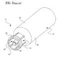
- FIG. 5is an isometric view of a connector with a preferred embodiment of the male connector interface of the present invention.
- FIG. 6is a side cutaway view of a preferred embodiment of the male connector interface of the present invention in mating engagement with a known female connector interface.
- FIG. 7is a schematic view of a test setup similar to that of FIG. 1 but the test connector has male connector interfaces, representative of the pre-test state before engagement of the test connector and the device under test, and also representative of the post-test state after disengagement of the test connector and the device under test, wherein none of the blind mate connectors are separated from the device under test and carried away by the test connector subsequent to testing.
- FIG. 5illustrates one preferred embodiment of a male connector interface 80 of the present invention which, in the present example, forms part of a connector 90 which also has a female interface 92 opposite to the male interface.
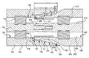
- FIG. 6illustrates a preferred embodiment of a male connector interface 100 of the present invention in mating engagement with a female connector interface.
- the male connector interface 100comprises a tubular housing 102 comprising an inner surface 104 that defines a longitudinal bore 106 along a longitudinal axis of the housing 102 .
- the bore 106is a through-bore, although in other embodiments the bore may not pass all the way through the body.
- the housing 102has a distal end 108 .
- the housing 102is made from an electrically conductive material, preferably metal, and serves as an outer conductor. In preferred embodiments, the housing 102 is made from brass, copper, kovar, or stainless steel.
- a central terminal 110is disposed within the longitudinal bore 106 of the housing 102 .
- the central terminal 110is made from an electrically conductive material, preferably metal, and serves as an inner conductor.
- the central terminal 110is made from brass, copper, kovar, or stainless steel.
- a dielectric support member 112is disposed on the inner surface of the housing and holds the central terminal 110 within the longitudinal bore 106 and away from the inner surface 104 of the housing 102 , such that the central terminal 110 does not contact (directly contact) the inner surface 104 of the housing 102 .
- the support member 112is made from an electrically nonconductive material, such as ptfe (Teflon®) or glass such as Corning 7070 glass.
- the inner surface 104 of the housing 102comprises a first inner diameter region 120 having an inner diameter D 1 , and an increased inner diameter region 130 having a first end 132 disposed directly adjacent the first inner diameter region 120 and extending to the distal end 108 of the housing 102 for an axial distance L 1 .
- the first end 132has an inner diameter D 2 , and D 2 >D 1 .
- the first inner diameter region 120 and the first end 132 of the increased inner diameter region 130define a step or a shoulder 134 facing the distal end 108 of the housing 102 .
- the increased inner diameter region 130comprises a first tapered portion 140 disposed at the first end 132 , and extending from the first end 132 for an axial distance L 2 , and having increasing inner diameters within the axial distance L 2 with increasing longitudinal distance away from the first end 132 .
- the shoulder 134is substantially orthogonal to the longitudinal axis, even more preferably the shoulder 134 is perpendicular to the longitudinal axis.
- the first tapered portion 140defines a first generally frustoconical bore portion 141 of the longitudinal bore 106 .
- the first tapered portion 140has a monotonically increasing inner diameter with axial length in the direction of the distal end 108 .
- the tapered portion 140has a series of minute steps, such as steps that have a depth smaller than the depth of the shoulder 134 .
- 0.1 ⁇ L 2 /L 1⁇ 1.0. In some preferred embodiments, 0.2 ⁇ L 2 /L 1 ⁇ 0.8. In other preferred embodiments, 0.3 ⁇ L 2 /L 1 ⁇ 0.7. In the preferred embodiment illustrated in FIG. 6 , L 2 /L 1 is about 0.5. In some embodiments, the first tapered portion 140 extends all the way to distal end 108 .
- the increased inner diameter region 130here also comprises an optional second tapered portion 150 extending axially for a length L 3 .
- the ratio L 3 /L 1is greater than or equal to 0 and less than (1 ⁇ L 2 /L 1 ). In some preferred embodiments, 0.2 ⁇ L 3 /L 1 ⁇ 0.8. In other preferred embodiments, 0.3 ⁇ L 3 /L 1 ⁇ 0.6. In the preferred embodiment illustrated in FIG. 6 , L 3 /L 1 is about 0.4, and L 4 /L 1 is about 0.1.
- the first tapered portion 140is disposed directly adjacent to and extending away from the shoulder 134 .
- the first tapered portion 140defines a first acute angle ⁇ 1 with the longitudinal axis.
- ⁇ 1is about 6°.
- the second tapered portion 150defines a second acute angle ⁇ 2 with the longitudinal axis, wherein ⁇ 2 > ⁇ 1 .
- ⁇ 1 ⁇ 2 ⁇ 45°is about 16°.
- the second tapered portion 150is disposed between the first tapered portion 140 and the distal end 108 .
- the increased diameter region 130further comprises an optional third inner surface section having a substantially constant diameter D 3 , and D 3 >D 2 >D 1 .
- the increased diameter region 130further comprises an optional chamfered inner surface section 160 disposed at the distal end 108 of the housing 102 .
- FIG. 6illustrates a combination of one preferred embodiment of a male connector interface 100 and a mating female connector interface 200 , the female connector interface comprising a tubular outer housing 202 comprising an inner surface 204 defining a longitudinal bore 206 , preferably a throughbore, along a longitudinal axis of the outer housing 202 .
- the outer housing 202comprises a tubular body 203 and a plurality of fingers 209 that extend from the tubular body 203 to a leading end 208 .
- a center terminal 210is disposed within the longitudinal bore 206 of the outer housing 202 and adapted to receive the central terminal 110 of the male connector interface 100 .
- the outer housing 202 and the center terminal 210are made from electrically conductive material, preferably metal, such as brass, copper, kovar, or stainless steel.
- a dielectric support member 212is disposed on the inner surface 204 of the outer housing 202 and holds the center terminal 210 within the longitudinal bore 206 and away from the inner surface 204 of the outer housing 202 , wherein the center terminal 210 does not contact (directly contact) the inner surface 204 of the outer housing 202 .
- the support member 210is made from an electrically nonconductive material, such as ptfe (Teflon®) or glass such as Corning 7070 glass.
- the increased inner diameter region 130 of the male connector interface 100is adapted to receive the plurality of fingers 209 .
- Each of the plurality of fingers 209has a protrusion 211 disposed at or near the leading end 208 .
- the protrusion 211may comprise a chamfered or frustoconical outer surface portion as illustrated in FIG. 6 , or the protrusion may have a more bulbous or spherical contour.
- the protrusion 211has an outer surface that mates with at least part of the first tapered portion 140 of the male connector interface 100 .
- the contour of at least part of the protrusion 211 and the contour of the first tapered portion 140preferably match.
- the protrusion 211contacts the first tapered portion 140 when the male and female connector interfaces are fully mated together.
- the leading end 208 of the tubular outer housing 202contacts the shoulder 134 when the male and female connector interfaces are fully mated together.
- the leading end of the tubular outer housingcould be spaced away from the shoulder by a small axial gap.
- the protrusioncontacts both the tapered portion, and the leading end of the tubular outer housing contacts the shoulder, when the male and female connector interfaces are fully mated together, as shown in FIG. 6 .
- a first body(such as a connector) which comprises a male connector interface and a second body (such as another connector) which comprises a female connector interface capable of mating with the male connector interface and moved into mutual engagement.
- the first body and/or the second bodycould have a cable mounted opposite its respective interface, or the side opposite to the interface could be configured to attach to a PCB board, a metal panel, a wave guide, or other components.
- the body (or connector)could comprise two interfaces to form an adapter.
- the plurality of fingers 209 of the outer housing 202 of the female interface 200are guided into engagement with the increased inner diameter region 130 of the male interface 100 , and the male central terminal 110 of the male interface is guided into engagement with the female center terminal 210 of the female interface.
- the female center terminal 210comprises radially inwardly biased flexible fingers 229 that form a socket that receives the central terminal 110 of the male interface 100 .
- the fingers 229are spread apart by the entry of the central terminal 110 to allow a snug but releasable physical fit while allowing a good electrical contact to be established therebetween.
- the plurality of fingers 209 of the outer housing 202 of the female interface 200are spread radially outward and are disposed at an angle with respect to the longitudinal axis prior to engagement in a freestanding state, and then engagement between the male 100 and female 200 interfaces, and in particular engagement between the protrusions of the fingers 209 and the increased inner diameter region 130 of the male interface, causes the fingers 209 to deflect radially inwardly.
- the increased inner diameter region 130 and the plurality of fingers 209are mutually adapted to allow the inner surfaces of the plurality of fingers 209 to lie parallel to or at a precise acute angle to an outer surface of the center terminal 210 when the male and female connector interfaces are fully mated together, as illustrated in FIG. 6 .
- the present inventionrelates to a method of testing a device-under-test with a test connector comprising the male connector interface of the present invention.
- the device under testhas coaxial connectors each with a male connector interface with a blind mate connector pre-installed.
- a mating male connector interface for each of the female interfacesis adapted to mate with respective female connector interfaces. For illustration purposes, only one of the male interfaces is shown by cutaway of the test connector.
- the methodcomprises the sequential steps of moving the test connector toward the device under test to engage the male connector interface with the female connector interface such that the device under test and the test connector are electrically connected to each other, transmitting test information through the male connector interface and female connector interface, and moving the test connector away from the device under test such that the device under test and the test connector are electrically disconnected from each other, wherein the blind mate connector is disengaged from the male connector interface.
- the male and female interfacesare temporarily brought together with a sufficient axial force, but the interfaces are easily separable upon termination of the axial force.
- FIG. 7schematically represents both the “before engagement and testing” and “after testing and disengagement”, wherein all of the connectors that were initially installed on the device under test also remained on the device under test after conclusion of the test.
- the non-sticking engagement between the male and female interfacesis provided by the male interface of the present invention.
- the present inventionalso relates to a test interface apparatus for interconnecting a device under test with an analyzer and supply for testing the device (which could include one or cables), the device comprising a female connector interface, the apparatus comprising a test structure having an interface surface adapted to receive the device under test and having the male connector interface of the present invention, wherein the male connector interface is adapted to engage the female interface.
- the male connector interface of the present inventionis particularly suited for testing purposes because it provides a non-locking, temporary connection between male and female interfaces to allow a good physical and electrical contact during a test wherein a sufficient axial force is applied to engage the male and female interfaces, but which also allows rapid and easy disengagement of the male and female interfaces upon removal of that axial force.
- the male connector interfaceis easily separable from the female connector interface upon termination of the axial force that keeps the male and female interfaces in mutual engagement during testing.
Landscapes
- Details Of Connecting Devices For Male And Female Coupling (AREA)
Abstract
Description
Claims (19)
Priority Applications (1)
| Application Number | Priority Date | Filing Date | Title |
|---|---|---|---|
| US11/429,001US7563133B2 (en) | 2005-07-01 | 2006-05-04 | Low extraction force connector interface |
Applications Claiming Priority (2)
| Application Number | Priority Date | Filing Date | Title |
|---|---|---|---|
| US69600405P | 2005-07-01 | 2005-07-01 | |
| US11/429,001US7563133B2 (en) | 2005-07-01 | 2006-05-04 | Low extraction force connector interface |
Publications (2)
| Publication Number | Publication Date |
|---|---|
| US20070004276A1 US20070004276A1 (en) | 2007-01-04 |
| US7563133B2true US7563133B2 (en) | 2009-07-21 |
Family
ID=37590205
Family Applications (1)
| Application Number | Title | Priority Date | Filing Date |
|---|---|---|---|
| US11/429,001Active2026-07-19US7563133B2 (en) | 2005-07-01 | 2006-05-04 | Low extraction force connector interface |
Country Status (1)
| Country | Link |
|---|---|
| US (1) | US7563133B2 (en) |
Cited By (46)
| Publication number | Priority date | Publication date | Assignee | Title |
|---|---|---|---|---|
| US20110130048A1 (en)* | 2008-07-24 | 2011-06-02 | Kathrein-Werke Kg | Plug connector and plug connector set |
| US20120122325A1 (en)* | 2010-11-16 | 2012-05-17 | Compal Electronics, Inc. | Connecting port |
| US20130065415A1 (en)* | 2010-11-22 | 2013-03-14 | Andrew Llc | Blind Mate Capacitively Coupled Connector |
| US20140073160A1 (en)* | 2012-09-12 | 2014-03-13 | Hypertronics Corporation | Self-adjusting coaxial contact |
| US20140134878A1 (en)* | 2012-11-09 | 2014-05-15 | Andrew Llc | RF Shielded Capacitively Coupled Connector |
| US8747152B2 (en)* | 2012-11-09 | 2014-06-10 | Andrew Llc | RF isolated capacitively coupled connector |
| US20140193995A1 (en)* | 2013-01-09 | 2014-07-10 | Amphenol Corporation | Electrical connector assembly with high float bullet adapter |
| US8888519B2 (en) | 2012-05-31 | 2014-11-18 | Cinch Connectivity Solutions, Inc. | Modular RF connector system |
| US8888526B2 (en) | 2010-08-10 | 2014-11-18 | Corning Gilbert, Inc. | Coaxial cable connector with radio frequency interference and grounding shield |
| US9048599B2 (en) | 2013-10-28 | 2015-06-02 | Corning Gilbert Inc. | Coaxial cable connector having a gripping member with a notch and disposed inside a shell |
| US9071019B2 (en) | 2010-10-27 | 2015-06-30 | Corning Gilbert, Inc. | Push-on cable connector with a coupler and retention and release mechanism |
| US9136654B2 (en) | 2012-01-05 | 2015-09-15 | Corning Gilbert, Inc. | Quick mount connector for a coaxial cable |
| US9147963B2 (en) | 2012-11-29 | 2015-09-29 | Corning Gilbert Inc. | Hardline coaxial connector with a locking ferrule |
| US9153911B2 (en) | 2013-02-19 | 2015-10-06 | Corning Gilbert Inc. | Coaxial cable continuity connector |
| US9166348B2 (en) | 2010-04-13 | 2015-10-20 | Corning Gilbert Inc. | Coaxial connector with inhibited ingress and improved grounding |
| US9172154B2 (en) | 2013-03-15 | 2015-10-27 | Corning Gilbert Inc. | Coaxial cable connector with integral RFI protection |
| US9190744B2 (en) | 2011-09-14 | 2015-11-17 | Corning Optical Communications Rf Llc | Coaxial cable connector with radio frequency interference and grounding shield |
| US9287659B2 (en) | 2012-10-16 | 2016-03-15 | Corning Optical Communications Rf Llc | Coaxial cable connector with integral RFI protection |
| US9356374B2 (en) | 2013-01-09 | 2016-05-31 | Amphenol Corporation | Float adapter for electrical connector |
| US9407016B2 (en) | 2012-02-22 | 2016-08-02 | Corning Optical Communications Rf Llc | Coaxial cable connector with integral continuity contacting portion |
| US9484650B2 (en) | 2012-09-12 | 2016-11-01 | Hypertronics Corporation | Self-adjusting coaxial contact |
| US9502825B2 (en) | 2013-03-14 | 2016-11-22 | Amphenol Corporation | Shunt for electrical connector |
| US9525220B1 (en) | 2015-11-25 | 2016-12-20 | Corning Optical Communications LLC | Coaxial cable connector |
| US9548557B2 (en) | 2013-06-26 | 2017-01-17 | Corning Optical Communications LLC | Connector assemblies and methods of manufacture |
| US9548572B2 (en) | 2014-11-03 | 2017-01-17 | Corning Optical Communications LLC | Coaxial cable connector having a coupler and a post with a contacting portion and a shoulder |
| US9590287B2 (en) | 2015-02-20 | 2017-03-07 | Corning Optical Communications Rf Llc | Surge protected coaxial termination |
| US9735521B2 (en) | 2013-01-09 | 2017-08-15 | Amphenol Corporation | Float adapter for electrical connector |
| US9762008B2 (en) | 2013-05-20 | 2017-09-12 | Corning Optical Communications Rf Llc | Coaxial cable connector with integral RFI protection |
| US9859631B2 (en) | 2011-09-15 | 2018-01-02 | Corning Optical Communications Rf Llc | Coaxial cable connector with integral radio frequency interference and grounding shield |
| US9979128B2 (en)* | 2015-02-12 | 2018-05-22 | Cisco Technology, Inc. | Radial centering mechanism for floating connection devices |
| US10033122B2 (en) | 2015-02-20 | 2018-07-24 | Corning Optical Communications Rf Llc | Cable or conduit connector with jacket retention feature |
| US10211547B2 (en) | 2015-09-03 | 2019-02-19 | Corning Optical Communications Rf Llc | Coaxial cable connector |
| US10290958B2 (en) | 2013-04-29 | 2019-05-14 | Corning Optical Communications Rf Llc | Coaxial cable connector with integral RFI protection and biasing ring |
| US10756455B2 (en) | 2005-01-25 | 2020-08-25 | Corning Optical Communications Rf Llc | Electrical connector with grounding member |
| US11411336B2 (en) | 2018-02-26 | 2022-08-09 | Eaton Intelligent Power Limited | Spring-actuated electrical connector for high-power applications |
| US20220285863A1 (en)* | 2019-11-30 | 2022-09-08 | Corning Optical Communications Rf Llc | Connector assemblies |
| US11476609B2 (en)* | 2018-06-07 | 2022-10-18 | Eaton Intelligent Power Limited | Electrical connector system with internal spring component and applications thereof |
| US11721927B2 (en) | 2019-09-09 | 2023-08-08 | Royal Precision Products Llc | Connector recording system with readable and recordable indicia |
| US11721942B2 (en) | 2019-09-09 | 2023-08-08 | Eaton Intelligent Power Limited | Connector system for a component in a power management system in a motor vehicle |
| US20230382322A1 (en)* | 2022-05-26 | 2023-11-30 | Kodiak Robotics, Inc. | Connecting assembly for a sensor pod |
| US11870175B2 (en) | 2016-09-30 | 2024-01-09 | Eaton Intelligent Power Limited | Spring-actuated electrical connector for high-power applications |
| US11929572B2 (en) | 2020-07-29 | 2024-03-12 | Eaton Intelligent Power Limited | Connector system including an interlock system |
| US11990720B2 (en) | 2019-01-21 | 2024-05-21 | Eaton Intelligent Power Limited | Power distribution assembly with boltless busbar system |
| US12034264B2 (en) | 2021-03-31 | 2024-07-09 | Corning Optical Communications Rf Llc | Coaxial cable connector assemblies with outer conductor engagement features and methods for using the same |
| US12212083B2 (en) | 2020-11-30 | 2025-01-28 | Corning Optical Communications Rf Llc | Compressible electrical assemblies with divaricated-cut sections |
| US12237605B2 (en) | 2019-01-15 | 2025-02-25 | Eaton Intelligent Power Limited | Shielded electrical connector system with internal spring component |
Families Citing this family (11)
| Publication number | Priority date | Publication date | Assignee | Title |
|---|---|---|---|---|
| EP1848064B1 (en)* | 2006-04-22 | 2013-03-13 | Hirschmann Automotive GmbH | Connector with a contact chamber for a mating contact having a test slot in the contact chamber |
| US7500873B1 (en) | 2008-05-16 | 2009-03-10 | Corning Gilbert Inc. | Snap-on coaxial cable connector |
| US7677929B2 (en)* | 2008-06-04 | 2010-03-16 | Daphne Bradford-Stagg | Sacrificial laptop computer power connector |
| US20100015850A1 (en)* | 2008-07-15 | 2010-01-21 | Casey Roy Stein | Low-profile mounted push-on connector |
| CH704592A2 (en) | 2011-03-08 | 2012-09-14 | Huber+Suhner Ag | RF coaxial connector. |
| FR2994031A1 (en)* | 2012-07-27 | 2014-01-31 | Radiall Sa | HYPERFREQUENCY COAXIAL CONNECTOR FOR CONNECTING TWO CIRCUIT BOARD CARDS |
| DE102013111905B9 (en) | 2013-10-29 | 2015-10-29 | Telegärtner Karl Gärtner GmbH | Connecting device for electrically connecting two printed circuit boards |
| US9917399B2 (en)* | 2015-09-11 | 2018-03-13 | Tektronix, Inc. | Reduced stress electrical connector |
| US20180375258A1 (en)* | 2017-06-21 | 2018-12-27 | Dynawave Incorporated | Self-aligning cable mating connector |
| CN110197986A (en)* | 2018-02-24 | 2019-09-03 | 康普技术有限责任公司 | Coaxial connector |
| JP2024099885A (en)* | 2023-01-13 | 2024-07-26 | 株式会社オートネットワーク技術研究所 | Outer conductor and shield member |
Citations (10)
| Publication number | Priority date | Publication date | Assignee | Title |
|---|---|---|---|---|
| US4605269A (en)* | 1984-06-20 | 1986-08-12 | Amp Incorporated | Printed circuit board header having coaxial sockets therein and matable coaxial plug housing |
| US4697859A (en)* | 1986-08-15 | 1987-10-06 | Amp Incorporated | Floating coaxial connector |
| US4789351A (en) | 1988-04-29 | 1988-12-06 | Amp Incorporated | Blind mating connector with snap ring insertion |
| US4917630A (en)* | 1987-10-15 | 1990-04-17 | The Phoenix Company Of Chicago, Inc. | Constant impedance high frequency coaxial connector |
| US4925403A (en) | 1988-10-11 | 1990-05-15 | Gilbert Engineering Company, Inc. | Coaxial transmission medium connector |
| US5074809A (en)* | 1989-01-20 | 1991-12-24 | Alliance Technique Industrielle | Ultraminiature high-frequency connection interface |
| US5329262A (en)* | 1991-06-24 | 1994-07-12 | The Whitaker Corporation | Fixed RF connector having internal floating members with impedance compensation |
| US5474470A (en)* | 1994-03-30 | 1995-12-12 | Itt Corporation | Compensated interface coaxial connector apparatus |
| US6126487A (en) | 1997-02-04 | 2000-10-03 | Rosenberger Hochfrequenztechnik Gmbh And Co. | Coaxial connector socket |
| US6709289B2 (en)* | 2002-02-14 | 2004-03-23 | Huber & Suhner Ag | Electrical plug connector |
- 2006
- 2006-05-04USUS11/429,001patent/US7563133B2/enactiveActive
Patent Citations (10)
| Publication number | Priority date | Publication date | Assignee | Title |
|---|---|---|---|---|
| US4605269A (en)* | 1984-06-20 | 1986-08-12 | Amp Incorporated | Printed circuit board header having coaxial sockets therein and matable coaxial plug housing |
| US4697859A (en)* | 1986-08-15 | 1987-10-06 | Amp Incorporated | Floating coaxial connector |
| US4917630A (en)* | 1987-10-15 | 1990-04-17 | The Phoenix Company Of Chicago, Inc. | Constant impedance high frequency coaxial connector |
| US4789351A (en) | 1988-04-29 | 1988-12-06 | Amp Incorporated | Blind mating connector with snap ring insertion |
| US4925403A (en) | 1988-10-11 | 1990-05-15 | Gilbert Engineering Company, Inc. | Coaxial transmission medium connector |
| US5074809A (en)* | 1989-01-20 | 1991-12-24 | Alliance Technique Industrielle | Ultraminiature high-frequency connection interface |
| US5329262A (en)* | 1991-06-24 | 1994-07-12 | The Whitaker Corporation | Fixed RF connector having internal floating members with impedance compensation |
| US5474470A (en)* | 1994-03-30 | 1995-12-12 | Itt Corporation | Compensated interface coaxial connector apparatus |
| US6126487A (en) | 1997-02-04 | 2000-10-03 | Rosenberger Hochfrequenztechnik Gmbh And Co. | Coaxial connector socket |
| US6709289B2 (en)* | 2002-02-14 | 2004-03-23 | Huber & Suhner Ag | Electrical plug connector |
Non-Patent Citations (1)
| Title |
|---|
| Department of Defense, "Interface Standard Radio Frequency Connector Interfaces for MIL-C-3643, MIL-C-3650, MIL-C-3655, MIL-C-25516, MIL-C-26637, MIL-PRF-39012, MIL-PRF-49142, MIL-PRF-55339, MIL-C-83517", MIL-STD-348A Notice 6, Mar. 14, 2003, pp. Coversheet, 326.1, 326.1a, 326.2, 326.5, 328.1, 328.2, and 328.3. |
Cited By (72)
| Publication number | Priority date | Publication date | Assignee | Title |
|---|---|---|---|---|
| US10756455B2 (en) | 2005-01-25 | 2020-08-25 | Corning Optical Communications Rf Llc | Electrical connector with grounding member |
| US20110130048A1 (en)* | 2008-07-24 | 2011-06-02 | Kathrein-Werke Kg | Plug connector and plug connector set |
| US9905959B2 (en) | 2010-04-13 | 2018-02-27 | Corning Optical Communication RF LLC | Coaxial connector with inhibited ingress and improved grounding |
| US10312629B2 (en) | 2010-04-13 | 2019-06-04 | Corning Optical Communications Rf Llc | Coaxial connector with inhibited ingress and improved grounding |
| US9166348B2 (en) | 2010-04-13 | 2015-10-20 | Corning Gilbert Inc. | Coaxial connector with inhibited ingress and improved grounding |
| US8888526B2 (en) | 2010-08-10 | 2014-11-18 | Corning Gilbert, Inc. | Coaxial cable connector with radio frequency interference and grounding shield |
| US9071019B2 (en) | 2010-10-27 | 2015-06-30 | Corning Gilbert, Inc. | Push-on cable connector with a coupler and retention and release mechanism |
| US20120122325A1 (en)* | 2010-11-16 | 2012-05-17 | Compal Electronics, Inc. | Connecting port |
| US8562364B2 (en)* | 2010-11-16 | 2013-10-22 | Compal Electronics, Inc. | Connecting port |
| US8622762B2 (en)* | 2010-11-22 | 2014-01-07 | Andrew Llc | Blind mate capacitively coupled connector |
| US20130065415A1 (en)* | 2010-11-22 | 2013-03-14 | Andrew Llc | Blind Mate Capacitively Coupled Connector |
| US9190744B2 (en) | 2011-09-14 | 2015-11-17 | Corning Optical Communications Rf Llc | Coaxial cable connector with radio frequency interference and grounding shield |
| US9859631B2 (en) | 2011-09-15 | 2018-01-02 | Corning Optical Communications Rf Llc | Coaxial cable connector with integral radio frequency interference and grounding shield |
| US9768565B2 (en) | 2012-01-05 | 2017-09-19 | Corning Optical Communications Rf Llc | Quick mount connector for a coaxial cable |
| US9484645B2 (en) | 2012-01-05 | 2016-11-01 | Corning Optical Communications Rf Llc | Quick mount connector for a coaxial cable |
| US9136654B2 (en) | 2012-01-05 | 2015-09-15 | Corning Gilbert, Inc. | Quick mount connector for a coaxial cable |
| US9407016B2 (en) | 2012-02-22 | 2016-08-02 | Corning Optical Communications Rf Llc | Coaxial cable connector with integral continuity contacting portion |
| US8888519B2 (en) | 2012-05-31 | 2014-11-18 | Cinch Connectivity Solutions, Inc. | Modular RF connector system |
| US9190786B1 (en) | 2012-05-31 | 2015-11-17 | Cinch Connectivity Solutions Inc. | Modular RF connector system |
| US8956169B2 (en)* | 2012-09-12 | 2015-02-17 | Hypertronics Corporation | Self-adjusting coaxial contact |
| US9484650B2 (en) | 2012-09-12 | 2016-11-01 | Hypertronics Corporation | Self-adjusting coaxial contact |
| US20140073160A1 (en)* | 2012-09-12 | 2014-03-13 | Hypertronics Corporation | Self-adjusting coaxial contact |
| US10236636B2 (en) | 2012-10-16 | 2019-03-19 | Corning Optical Communications Rf Llc | Coaxial cable connector with integral RFI protection |
| US9287659B2 (en) | 2012-10-16 | 2016-03-15 | Corning Optical Communications Rf Llc | Coaxial cable connector with integral RFI protection |
| US9912105B2 (en) | 2012-10-16 | 2018-03-06 | Corning Optical Communications Rf Llc | Coaxial cable connector with integral RFI protection |
| US9722363B2 (en) | 2012-10-16 | 2017-08-01 | Corning Optical Communications Rf Llc | Coaxial cable connector with integral RFI protection |
| US8801460B2 (en)* | 2012-11-09 | 2014-08-12 | Andrew Llc | RF shielded capacitively coupled connector |
| US8747152B2 (en)* | 2012-11-09 | 2014-06-10 | Andrew Llc | RF isolated capacitively coupled connector |
| US20140134878A1 (en)* | 2012-11-09 | 2014-05-15 | Andrew Llc | RF Shielded Capacitively Coupled Connector |
| US9147963B2 (en) | 2012-11-29 | 2015-09-29 | Corning Gilbert Inc. | Hardline coaxial connector with a locking ferrule |
| US9735531B2 (en) | 2013-01-09 | 2017-08-15 | Amphenol Corporation | Float adapter for electrical connector and method for making the same |
| US20140193995A1 (en)* | 2013-01-09 | 2014-07-10 | Amphenol Corporation | Electrical connector assembly with high float bullet adapter |
| US9653831B2 (en) | 2013-01-09 | 2017-05-16 | Amphenol Corporation | Float adapter for electrical connector |
| US9039433B2 (en)* | 2013-01-09 | 2015-05-26 | Amphenol Corporation | Electrical connector assembly with high float bullet adapter |
| US9735521B2 (en) | 2013-01-09 | 2017-08-15 | Amphenol Corporation | Float adapter for electrical connector |
| US9356374B2 (en) | 2013-01-09 | 2016-05-31 | Amphenol Corporation | Float adapter for electrical connector |
| US9153911B2 (en) | 2013-02-19 | 2015-10-06 | Corning Gilbert Inc. | Coaxial cable continuity connector |
| US9502825B2 (en) | 2013-03-14 | 2016-11-22 | Amphenol Corporation | Shunt for electrical connector |
| US9172154B2 (en) | 2013-03-15 | 2015-10-27 | Corning Gilbert Inc. | Coaxial cable connector with integral RFI protection |
| US10290958B2 (en) | 2013-04-29 | 2019-05-14 | Corning Optical Communications Rf Llc | Coaxial cable connector with integral RFI protection and biasing ring |
| US9762008B2 (en) | 2013-05-20 | 2017-09-12 | Corning Optical Communications Rf Llc | Coaxial cable connector with integral RFI protection |
| US10396508B2 (en) | 2013-05-20 | 2019-08-27 | Corning Optical Communications Rf Llc | Coaxial cable connector with integral RFI protection |
| US9548557B2 (en) | 2013-06-26 | 2017-01-17 | Corning Optical Communications LLC | Connector assemblies and methods of manufacture |
| US9048599B2 (en) | 2013-10-28 | 2015-06-02 | Corning Gilbert Inc. | Coaxial cable connector having a gripping member with a notch and disposed inside a shell |
| US9548572B2 (en) | 2014-11-03 | 2017-01-17 | Corning Optical Communications LLC | Coaxial cable connector having a coupler and a post with a contacting portion and a shoulder |
| US9991651B2 (en) | 2014-11-03 | 2018-06-05 | Corning Optical Communications Rf Llc | Coaxial cable connector with post including radially expanding tabs |
| US9979128B2 (en)* | 2015-02-12 | 2018-05-22 | Cisco Technology, Inc. | Radial centering mechanism for floating connection devices |
| US10033122B2 (en) | 2015-02-20 | 2018-07-24 | Corning Optical Communications Rf Llc | Cable or conduit connector with jacket retention feature |
| US9590287B2 (en) | 2015-02-20 | 2017-03-07 | Corning Optical Communications Rf Llc | Surge protected coaxial termination |
| US10211547B2 (en) | 2015-09-03 | 2019-02-19 | Corning Optical Communications Rf Llc | Coaxial cable connector |
| US9525220B1 (en) | 2015-11-25 | 2016-12-20 | Corning Optical Communications LLC | Coaxial cable connector |
| US9882320B2 (en) | 2015-11-25 | 2018-01-30 | Corning Optical Communications Rf Llc | Coaxial cable connector |
| US12308550B2 (en) | 2016-09-30 | 2025-05-20 | Eaton Intelligent Power Limited | Spring-actuated electrical connector for high-power applications |
| US11870175B2 (en) | 2016-09-30 | 2024-01-09 | Eaton Intelligent Power Limited | Spring-actuated electrical connector for high-power applications |
| US11721924B2 (en) | 2018-02-26 | 2023-08-08 | Royal Precision Products Llc | Spring-actuated electrical connector for high-power applications |
| US11411336B2 (en) | 2018-02-26 | 2022-08-09 | Eaton Intelligent Power Limited | Spring-actuated electrical connector for high-power applications |
| US11715899B2 (en) | 2018-06-07 | 2023-08-01 | Royal Precision Products Llc | Electrical connector assembly with internal spring component |
| US11715900B2 (en) | 2018-06-07 | 2023-08-01 | Royal Precision Products Llc | Electrical connector system with internal spring component and applications thereof |
| US11476609B2 (en)* | 2018-06-07 | 2022-10-18 | Eaton Intelligent Power Limited | Electrical connector system with internal spring component and applications thereof |
| US12237605B2 (en) | 2019-01-15 | 2025-02-25 | Eaton Intelligent Power Limited | Shielded electrical connector system with internal spring component |
| US12381338B2 (en) | 2019-01-21 | 2025-08-05 | Eaton Intelligent Power Limited | Power distribution assembly with boltless busbar system |
| US11990720B2 (en) | 2019-01-21 | 2024-05-21 | Eaton Intelligent Power Limited | Power distribution assembly with boltless busbar system |
| US11721927B2 (en) | 2019-09-09 | 2023-08-08 | Royal Precision Products Llc | Connector recording system with readable and recordable indicia |
| US11721942B2 (en) | 2019-09-09 | 2023-08-08 | Eaton Intelligent Power Limited | Connector system for a component in a power management system in a motor vehicle |
| US12237610B2 (en) | 2019-09-09 | 2025-02-25 | Eaton Intelligent Power Limited | Connector recording system with readable and recordable indicia |
| US12132286B2 (en) | 2019-09-09 | 2024-10-29 | Eaton Intelligent Power Limited | Connector system for a component in a power management system in a motor vehicle |
| US12176638B2 (en)* | 2019-11-30 | 2024-12-24 | Corning Optical Communications RF, LLC | Connector assemblies |
| US20220285863A1 (en)* | 2019-11-30 | 2022-09-08 | Corning Optical Communications Rf Llc | Connector assemblies |
| US11929572B2 (en) | 2020-07-29 | 2024-03-12 | Eaton Intelligent Power Limited | Connector system including an interlock system |
| US12212083B2 (en) | 2020-11-30 | 2025-01-28 | Corning Optical Communications Rf Llc | Compressible electrical assemblies with divaricated-cut sections |
| US12034264B2 (en) | 2021-03-31 | 2024-07-09 | Corning Optical Communications Rf Llc | Coaxial cable connector assemblies with outer conductor engagement features and methods for using the same |
| US20230382322A1 (en)* | 2022-05-26 | 2023-11-30 | Kodiak Robotics, Inc. | Connecting assembly for a sensor pod |
Also Published As
| Publication number | Publication date |
|---|---|
| US20070004276A1 (en) | 2007-01-04 |
Similar Documents
| Publication | Publication Date | Title |
|---|---|---|
| US7563133B2 (en) | Low extraction force connector interface | |
| US5938465A (en) | Machined dual spring ring connector for coaxial cable | |
| US7500873B1 (en) | Snap-on coaxial cable connector | |
| US8597050B2 (en) | Digital, small signal and RF microwave coaxial subminiature push-on differential pair system | |
| US7347726B2 (en) | Push-on connector interface | |
| US7455550B1 (en) | Snap-on coaxial plug | |
| US6210221B1 (en) | Microwave quick connect/disconnect coaxial connectors | |
| US7210941B2 (en) | Coaxial plug-and-socket connector having resilient tolerance compensation | |
| US7306484B1 (en) | Coax-to-power adapter | |
| CA2673700C (en) | Center conductor terminal having increased contact resistance | |
| US9431780B2 (en) | Coaxial adapter with an adapter body forward projecting member | |
| EP2826106B1 (en) | Push-on electrical connector system and method for transferring an electrical signal therewith | |
| EP3022808B1 (en) | Rf coaxial connectors | |
| EP3133697B1 (en) | Test connector for coaxial cables | |
| US20200021055A1 (en) | Ganged coaxial connector assembly | |
| US20080108242A1 (en) | High frequency self-lock connector | |
| US9614302B2 (en) | Right angle coaxial cable and connector assembly | |
| US20060189188A1 (en) | Mini-coaxial cable splice connector assemblies and wall mount installation tool therefor | |
| US11355880B2 (en) | Coaxial connector with axially-floating inner contact | |
| EP3048673A1 (en) | Low passive intermodulation coaxial connector test interface | |
| US11125810B2 (en) | Blind-mate PIM testing adapter connector and fixture | |
| US20250105553A1 (en) | Plug and adaptor for rf coaxial cable and rf connector assembly comprising same | |
| US6322390B1 (en) | Coaxial connector | |
| CN117616647A (en) | Electrical connector assembly with RF impedance element | |
| EP2417670B1 (en) | Low profile compact rf coaxial to planar transmission line interface |
Legal Events
| Date | Code | Title | Description |
|---|---|---|---|
| AS | Assignment | Owner name:CORNING GILBERT INC., ARIZONA Free format text:ASSIGNMENT OF ASSIGNORS INTEREST;ASSIGNOR:STEIN, CASEY ROY;REEL/FRAME:017843/0406 Effective date:20060426 | |
| STCF | Information on status: patent grant | Free format text:PATENTED CASE | |
| FPAY | Fee payment | Year of fee payment:4 | |
| AS | Assignment | Owner name:CORNING OPTICAL COMMUNICATIONS RF LLC, ARIZONA Free format text:CHANGE OF NAME;ASSIGNOR:CORNING GILBERT, INC.;REEL/FRAME:036687/0562 Effective date:20140122 | |
| FPAY | Fee payment | Year of fee payment:8 | |
| MAFP | Maintenance fee payment | Free format text:PAYMENT OF MAINTENANCE FEE, 12TH YEAR, LARGE ENTITY (ORIGINAL EVENT CODE: M1553); ENTITY STATUS OF PATENT OWNER: LARGE ENTITY Year of fee payment:12 | |
| AS | Assignment | Owner name:CORNING OPTICAL COMMUNICATIONS RF LLC, ARIZONA Free format text:CORRECTIVE ASSIGNMENT TO CORRECT THE PROPERTY LISTED IN THE ORIGINAL COVER SHEET PREVIOUSLY RECORDED AT REEL: 036687 FRAME: 0562. ASSIGNOR(S) HEREBY CONFIRMS THE ASSIGNMENT;ASSIGNOR:CORNING GILBERT, INC.;REEL/FRAME:058300/0843 Effective date:20140122 |