US7563008B2 - LED projector headlamps using single or multi-faceted lenses - Google Patents
LED projector headlamps using single or multi-faceted lensesDownload PDFInfo
- Publication number
- US7563008B2 US7563008B2US11/391,067US39106706AUS7563008B2US 7563008 B2US7563008 B2US 7563008B2US 39106706 AUS39106706 AUS 39106706AUS 7563008 B2US7563008 B2US 7563008B2
- Authority
- US
- United States
- Prior art keywords
- light
- condenser lens
- facets
- horizontal
- curvature
- Prior art date
- Legal status (The legal status is an assumption and is not a legal conclusion. Google has not performed a legal analysis and makes no representation as to the accuracy of the status listed.)
- Expired - Fee Related, expires
Links
Images


Classifications
- B—PERFORMING OPERATIONS; TRANSPORTING
- B60—VEHICLES IN GENERAL
- B60Q—ARRANGEMENT OF SIGNALLING OR LIGHTING DEVICES, THE MOUNTING OR SUPPORTING THEREOF OR CIRCUITS THEREFOR, FOR VEHICLES IN GENERAL
- B60Q1/00—Arrangement of optical signalling or lighting devices, the mounting or supporting thereof or circuits therefor
- B60Q1/02—Arrangement of optical signalling or lighting devices, the mounting or supporting thereof or circuits therefor the devices being primarily intended to illuminate the way ahead or to illuminate other areas of way or environments
- B60Q1/04—Arrangement of optical signalling or lighting devices, the mounting or supporting thereof or circuits therefor the devices being primarily intended to illuminate the way ahead or to illuminate other areas of way or environments the devices being headlights
- F—MECHANICAL ENGINEERING; LIGHTING; HEATING; WEAPONS; BLASTING
- F21—LIGHTING
- F21S—NON-PORTABLE LIGHTING DEVICES; SYSTEMS THEREOF; VEHICLE LIGHTING DEVICES SPECIALLY ADAPTED FOR VEHICLE EXTERIORS
- F21S41/00—Illuminating devices specially adapted for vehicle exteriors, e.g. headlamps
- F21S41/40—Illuminating devices specially adapted for vehicle exteriors, e.g. headlamps characterised by screens, non-reflecting members, light-shielding members or fixed shades
- F21S41/43—Illuminating devices specially adapted for vehicle exteriors, e.g. headlamps characterised by screens, non-reflecting members, light-shielding members or fixed shades characterised by the shape thereof
- F—MECHANICAL ENGINEERING; LIGHTING; HEATING; WEAPONS; BLASTING
- F21—LIGHTING
- F21S—NON-PORTABLE LIGHTING DEVICES; SYSTEMS THEREOF; VEHICLE LIGHTING DEVICES SPECIALLY ADAPTED FOR VEHICLE EXTERIORS
- F21S41/00—Illuminating devices specially adapted for vehicle exteriors, e.g. headlamps
- F21S41/10—Illuminating devices specially adapted for vehicle exteriors, e.g. headlamps characterised by the light source
- F21S41/14—Illuminating devices specially adapted for vehicle exteriors, e.g. headlamps characterised by the light source characterised by the type of light source
- F21S41/141—Light emitting diodes [LED]
- F21S41/147—Light emitting diodes [LED] the main emission direction of the LED being angled to the optical axis of the illuminating device
- F21S41/148—Light emitting diodes [LED] the main emission direction of the LED being angled to the optical axis of the illuminating device the main emission direction of the LED being perpendicular to the optical axis
- F—MECHANICAL ENGINEERING; LIGHTING; HEATING; WEAPONS; BLASTING
- F21—LIGHTING
- F21S—NON-PORTABLE LIGHTING DEVICES; SYSTEMS THEREOF; VEHICLE LIGHTING DEVICES SPECIALLY ADAPTED FOR VEHICLE EXTERIORS
- F21S41/00—Illuminating devices specially adapted for vehicle exteriors, e.g. headlamps
- F21S41/20—Illuminating devices specially adapted for vehicle exteriors, e.g. headlamps characterised by refractors, transparent cover plates, light guides or filters
- F21S41/25—Projection lenses
- F21S41/255—Lenses with a front view of circular or truncated circular outline
- F—MECHANICAL ENGINEERING; LIGHTING; HEATING; WEAPONS; BLASTING
- F21—LIGHTING
- F21S—NON-PORTABLE LIGHTING DEVICES; SYSTEMS THEREOF; VEHICLE LIGHTING DEVICES SPECIALLY ADAPTED FOR VEHICLE EXTERIORS
- F21S41/00—Illuminating devices specially adapted for vehicle exteriors, e.g. headlamps
- F21S41/20—Illuminating devices specially adapted for vehicle exteriors, e.g. headlamps characterised by refractors, transparent cover plates, light guides or filters
- F21S41/25—Projection lenses
- F21S41/26—Elongated lenses
- F—MECHANICAL ENGINEERING; LIGHTING; HEATING; WEAPONS; BLASTING
- F21—LIGHTING
- F21S—NON-PORTABLE LIGHTING DEVICES; SYSTEMS THEREOF; VEHICLE LIGHTING DEVICES SPECIALLY ADAPTED FOR VEHICLE EXTERIORS
- F21S41/00—Illuminating devices specially adapted for vehicle exteriors, e.g. headlamps
- F21S41/20—Illuminating devices specially adapted for vehicle exteriors, e.g. headlamps characterised by refractors, transparent cover plates, light guides or filters
- F21S41/25—Projection lenses
- F21S41/265—Composite lenses; Lenses with a patch-like shape
- F—MECHANICAL ENGINEERING; LIGHTING; HEATING; WEAPONS; BLASTING
- F21—LIGHTING
- F21S—NON-PORTABLE LIGHTING DEVICES; SYSTEMS THEREOF; VEHICLE LIGHTING DEVICES SPECIALLY ADAPTED FOR VEHICLE EXTERIORS
- F21S41/00—Illuminating devices specially adapted for vehicle exteriors, e.g. headlamps
- F21S41/30—Illuminating devices specially adapted for vehicle exteriors, e.g. headlamps characterised by reflectors
- F21S41/32—Optical layout thereof
- F21S41/321—Optical layout thereof the reflector being a surface of revolution or a planar surface, e.g. truncated
- F—MECHANICAL ENGINEERING; LIGHTING; HEATING; WEAPONS; BLASTING
- F21—LIGHTING
- F21S—NON-PORTABLE LIGHTING DEVICES; SYSTEMS THEREOF; VEHICLE LIGHTING DEVICES SPECIALLY ADAPTED FOR VEHICLE EXTERIORS
- F21S41/00—Illuminating devices specially adapted for vehicle exteriors, e.g. headlamps
- F21S41/30—Illuminating devices specially adapted for vehicle exteriors, e.g. headlamps characterised by reflectors
- F21S41/32—Optical layout thereof
- F21S41/36—Combinations of two or more separate reflectors
- F21S41/365—Combinations of two or more separate reflectors successively reflecting the light
- F—MECHANICAL ENGINEERING; LIGHTING; HEATING; WEAPONS; BLASTING
- F21—LIGHTING
- F21V—FUNCTIONAL FEATURES OR DETAILS OF LIGHTING DEVICES OR SYSTEMS THEREOF; STRUCTURAL COMBINATIONS OF LIGHTING DEVICES WITH OTHER ARTICLES, NOT OTHERWISE PROVIDED FOR
- F21V7/00—Reflectors for light sources
- F21V7/0025—Combination of two or more reflectors for a single light source
- F21V7/0033—Combination of two or more reflectors for a single light source with successive reflections from one reflector to the next or following
- F—MECHANICAL ENGINEERING; LIGHTING; HEATING; WEAPONS; BLASTING
- F21—LIGHTING
- F21W—INDEXING SCHEME ASSOCIATED WITH SUBCLASSES F21K, F21L, F21S and F21V, RELATING TO USES OR APPLICATIONS OF LIGHTING DEVICES OR SYSTEMS
- F21W2102/00—Exterior vehicle lighting devices for illuminating purposes
- F—MECHANICAL ENGINEERING; LIGHTING; HEATING; WEAPONS; BLASTING
- F21—LIGHTING
- F21Y—INDEXING SCHEME ASSOCIATED WITH SUBCLASSES F21K, F21L, F21S and F21V, RELATING TO THE FORM OR THE KIND OF THE LIGHT SOURCES OR OF THE COLOUR OF THE LIGHT EMITTED
- F21Y2101/00—Point-like light sources
- F—MECHANICAL ENGINEERING; LIGHTING; HEATING; WEAPONS; BLASTING
- F21—LIGHTING
- F21Y—INDEXING SCHEME ASSOCIATED WITH SUBCLASSES F21K, F21L, F21S and F21V, RELATING TO THE FORM OR THE KIND OF THE LIGHT SOURCES OR OF THE COLOUR OF THE LIGHT EMITTED
- F21Y2115/00—Light-generating elements of semiconductor light sources
- F21Y2115/10—Light-emitting diodes [LED]
Definitions
- the present inventionrelates generally to motor vehicle headlamps, and more particularly relates to headlamps of the projector-type which employ a condenser lens.
- LED'sLight emitting diodes
- headlampsi.e., headlights
- several requirementsmust be met. Specifically, the beam pattern provided in road illumination should have a certain amount of vertical spread as well as a certain amount of horizontal spread. At the same time, a vertical cut-off should be provided to minimize glare to oncoming traffic.
- headlamps for motor vehiclescan be characterized as reflector-type headlamps or projector-type headlamps.
- Reflector-type headlampsemploy a specially structured reflector unit which collects and redirects light from the light source, and are especially constructed to focus the light as well as provide the necessary beam spread.
- projector-type headlampsa standard projector unit employs a reflector that collects light from the LED light source and provides the beam spread. Light from the reflector passes through a condenser lens which simply and projects light from the reflector for illuminating the roadway. In a direct projector unit, no reflector is employed and a limited amount of control, is available over the beam spread through selection of the light source and its position relative to the condenser lens.
- the condenser lensis an imaging optic which simply projects the image placed at its focal point onto the road, thereby creating a beam pattern simply by inverting the source (left is right and up is down).
- These condenser lensesare aspheric lenses which are axi-symmetric and obtained by a surface revolution of a two-dimensional curve about the optic axis (i.e., a longitudinal axis extending through the lens center).
- the reflector of the standard projector-type headlampis elongated, primarily in the horizontal direction, in order to obtain the desired beam spread characteristics.
- the vertical beam spreadis about ⁇ 10° while the horizontal beam spread is about +/ ⁇ 35°.
- a condenser lensfor a projector-type headlamp assembly having a light source emitting light which is projected longitudinally downstream in front of a motor vehicle.
- the condenser lensgenerally includes a main body of light transmitting material. The main body defines a first surface receiving light from the light source and a second surface emitting the light. The second surface has at least one facet structured to spread the light and provide a predetermined beam pattern.
- the at least one facetseparates the horizontal beam spread from the vertical beam spread.
- the second surfacehas at least two facets and most preferably comprises a plurality of horizontally spaced facets extending vertically.
- the at least one facetmay comprise a single facet forming the second surface and having a saddle-shape.
- the curvature of each of the facets in the vertical directiondetermines the vertical spread
- the curvature of the plurality of facets in the horizontal directiondetermines the horizontal spread.
- the plurality of horizontally spaced facetsforms a series of peaks and valleys on the second surface.
- the vertical curvatures of the plurality of facetsare asymmetric relative to a horizontal axis in order to preserve the horizontal cut-off while generating the desired vertical beam spread.
- the facetsmay have either a convex curvature or a concave curvature in the horizontal direction. It will be recognized that the facets may be structured to create a predetermined beam pattern that includes regions of higher light intensity. Additionally, the cross-sectional shape of the condenser lens is no longer limited to being circular, and thus may take a square or rectangular shape to match the shape of the light emitting surface of the LED, or may take any other non-circular shape such as an oval or other oblong shapes.
- a projector-type headlamp assemblyfor a motor vehicle which generally includes a light source, a reflector, and a condenser lens.
- the condenser lensis constructed in a fashion similar to the numerous constructions described above, thereby providing a predetermined beam pattern.
- the reflectormay comprise a simple elliptical reflector having a circular cross-sectional shape. That is, the reflector need not be elongated in the horizontal direction or otherwise specifically constructed to generate the desired beam spread pattern.
- a shieldmay also be employed in the projector-type headlamp assembly to provide a horizontal cut-off. Preferably, the shield is tilted slightly away from the light source and toward the lens thereby improving light collection.
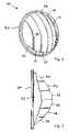
- FIG. 1is a perspective view of a condenser lens constructed in accordance with the teachings of the present invention
- FIG. 2is a bottom view of the condenser lens depicted in FIG. 1 ;
- FIG. 3is a side view of a headlamp assembly constructed in accordance with the teachings of the present invention and employing the condenser lens depicted in FIG. 1 ;
- FIG. 3Ais a front view of a reflector and light source forming a portion of the headlamp assembly depicted in FIG. 3 ;
- FIG. 4is a perspective view of the headlamp assembly depicted in FIG. 3 ;
- FIG. 5is a schematic view depicting a beam pattern produced by the headlamp assembly of FIG. 3 ;
- FIG. 6is a perspective view of another embodiment of a condenser lens constructed in accordance with the teachings of the present invention.
- FIG. 7is a bottom view of the condenser lens depicted in FIG. 6 ;
- FIG. 8is a perspective view of yet another embodiment of a condenser lens constructed in accordance with the teachings of the present invention.
- FIG. 9is a side view of the condenser lens depicted in FIG. 8 ;
- FIG. 10is a perspective view of still yet another embodiment of a condenser lens constructed in accordance with the teachings of the present invention.
- FIG. 11is a bottom view of the condenser lens depicted in FIG. 10 ;
- FIG. 12is a side view of the condenser lens depicted in FIG. 10 .
- FIGS. 1 and 2depict a condenser lens 30 constructed in accordance with the teachings of the present invention.
- the condenser lens 30is capable of imparting beam spread characteristics into the light outputted from the headlamp assembly 20 ( FIG. 3 ) of which it is a part of, as will be discussed in more detail herein below.
- the condenser lens 30is capable of creating specified vertical spread and horizontal spread functions for each facet, thereby providing a highly adaptable condenser lens which can be tailored for a specific number of vehicles or desired beam characteristics.
- standard elliptical reflectorsmay be employed in conjunction with LED light sources to provide a light output that is suitable for automotive headlight applications while also having the desired beam characteristics.
- the condenser lens 30generally comprises a main body 32 having a first surface 34 and a second surface 36 which are longitudinally spaced apart.
- the first surface 34receives light from the light source 22 ( FIG. 3 ) and is generally planar and perpendicular to a longitudinal axis 10 ( FIG. 3 ), although it can be curved.
- the longitudinal axis 10can also be considered the optical axis of the assembly 20 .
- the second surface 36is formed as a plurality of facets 38 , and particularly the embodiment of FIG. 2 includes six (6) facets although any number of facets may be readily employed.
- the facets 38are generally vertically extending while being horizontally spaced, although while it is possible to have facets that are both vertically and horizontally spaced like a checker board design pattern.
- Each of the facets 38have a generally convex curvature in the horizontal and vertical directions, and most preferably are numerically generated free form surfaces designed to provide a desired output beam.
- the vertical line where adjacent facets 38 meetare preferably as smooth as possible to avoid big steps between neighboring facets and depends on the nature of the particular horizontal curvatures of adjacent facets 38 . Given that each of the facets 38 may have their own horizontal curvature, a number of peaks and valleys are generally defined by the horizontal curvature of the second surface 36 .
- the headlamp assembly 20generally includes a light source 22 emitting light 24 which is collected and redirected by a reflector 26 .
- the light source 22is a LED which generally produces light from a surface area, as is known in the art.
- the reflector 26is preferably an elliptical reflector meaning it has an elliptical curvature as best seen from the side view of FIG.
- the reflector 26when the LED 22 is placed at the reflector's first focal point, the reflector 26 focuses light towards its second focal point 40 , which also generally coincides with a focal point of the condenser lens 30 , as is known in the art. It will be recognized by those skilled in the art that since the condenser lens 30 will be performing all or a portion of the beam spreading function, the reflector 26 may comprise a elliptical reflector having a generally circular cross-section, as best seen in FIG. 3A .
- a circular elliptical reflectoras depicted (or an oblong reflector of less width) results in a headlamp assembly 20 having reduced package size due to a reduced width (and possibly reduced height if the reflector 26 was performing some vertical beam spreading function).
- the light 24 produced from the LED light source 22is collected and focused toward the second focal point 40 where a shield 28 is positioned such that a portion of the light is redirected upwardly towards an upper half of the condenser lens 30 .
- the portion of the light 24 which would otherwise produce a upward beam divergenceis reflected as shown, whereby most if not all of the light exiting the second surface 36 of the condenser lens 30 is directed horizontally or slightly downwardly within the preferred vertical beam spread of ⁇ 10°.
- the reflective shield 28is preferably tilted slightly towards the condenser lens 30 , which has been found by the applicants to improve light collection by 3-15% depending upon the amount of the tilt.
- the rear or upstream end of the shield 28is tilted upwardly while the front end generally maintains its position in the vertical direction. It will also be recognized that flat or curved shields 28 of any shape may be employed and tilted as described.
- the shield 28is preferably tilted by about 0° to 6° relative to the longitudinal axis 10 .
- the curvature of the second surface 36controls the vertical beam spread.
- the vertical curvature of the second surface 36is asymmetric relative to the longitudinal axis 10 , whereby the outputted light 24 is skewed slightly downwardly to preserve the vertical cut-off while creating the desired vertical beam spread.
- the main body 32includes a semi-annular surface 33 resulting from the downward end 39 of the second surface 36 being spaced further away from the first surface 34 than an upper edge of the second surface 36 is spaced away from the first surface 34 causing a prism effect.
- both a horizontal spread and a vertical spreadcan be introduced into the light beam outputted by the headlamp assembly 20 .
- FIG. 4a schematic depiction of the headlamp assembly 20 shows the light source 22 having a rectangular shape such as would be produced by a LED light source, and which is positioned at a focal point 40 of the condenser lens 30 and relative to a vertical axis 12 , horizontal axis 14 and optical or longitudinal axis 10 .
- the headlamp assembly 20could include a direct projection headlamp whereby the LED 22 would be positioned generally as shown by numeral 22 in the FIG. 4 .
- the condenser lens 30receives light at its first surface 34 , and through the construction of the second surface 36 having a plurality of facets 38 , a predetermined beam pattern 44 is produced as shown in FIG.
- a predetermined beam pattern 44may be generated having increased horizontal spread as well as increased vertical spread.
- the predetermined beam pattern 44has a horizontal spread of +/ ⁇ 35° while the vertical spread is about 0° to minus 10°. It will also be recognized that through the tailoring of individual facets 38 , a hot spot, say for example the area indicated by dotted line 46 , can be created.
- each of the facets 38may have their own unique curvature in either or both of the vertical and horizontal directions which can be structured to overlap or separate the light the lens 30 outputs, thereby creating a predetermined beam spread pattern.
- facets 38were numbered consecutively from left to right, facets 2 and 5 could be utilized to create a particular hot spot or hot spots while the remainder of the facets could be structured to provide a more uniformly spread beam pattern. Accordingly, it will be recognized that the horizontal spread and vertical spread functions of the condenser lens 30 is separated by use of the horizontally spaced and vertically extending facets 38 .
- the condenser lens 130includes a main body 132 having a first surface 134 receiving light and a second surface 136 for emitting the light longitudinally downstream in front of the vehicle to illuminate the roadway.
- the second surface 136includes a plurality of facets 138 , which number three (3) in this embodiment.
- each of the facets 138has a horizontal curvature which is generally concave in shape, unlike the convex curvature given to the facets 38 of the prior embodiment.
- each of the facets 138includes a vertical curvature which is preferably asymmetric relative to the longitudinal axis or otherwise constructed to preserve the vertical cut-off while introducing a predetermined amount of vertical beam spread.
- the condenser lens 230generally includes a main body 232 having a first light receiving surface 234 and a second light emitting surface 236 .
- the second surface 236generally is formed by a plurality of horizontally spaced and vertically extending facets 238 which function to separate the horizontal spread and vertical spread functions of the condenser lens 230 .
- the vertical curvature of the second surface 236 and its facets 238is slightly asymmetric or tilted relative to a longitudinal axis to ensure the light is directed below the vertical cut-off.
- a lower end 239 of the lower edge 239 of the second surface 236is spaced further away from the first surface 234 than an upper edge.
- FIGS. 8 and 9provide a condenser lens 230 having a generally square or rectangular shape.
- the condenser lens 230may be shaped to correspond with the light source, such as an LED light source 22 which emits light from a surface such as a square or rectangular surface.
- the condenser lens 230and particularly as light receiving surface 234 , may take any shape, circular or non-circular, including rectangular, square, oval or other oblong shapes.
- unused material of the condenser lens 230can be eliminated, reducing the weight of the lens 230 and headlamp assembly, thereby providing a headlamp assembly which is lighter and smaller.
- the lens 330includes a main body 332 having a first light receiving surface 334 and a second light emitting surface 336 .
- the second surface 336includes a single facet 338 which thus itself defines the light emitting surface.
- the single facet 338(and hence second surface 336 ) has a saddle-shape which is curved in three dimensions and results in a separation of the horizontal spread and vertical spread of the predetermined beam pattern. As seen in the side view of FIG.
- the main body 332thus includes a peripheral surface 333 having a generally annular shape.
- the single facet 338 and second surface 336may be uniquely formed to provide any desired beam pattern and having predetermined vertical and horizontal beam spread.
- the surface 336is numerically generated to create the predetermined desired beam pattern.
- the present inventionprovides a condenser lens and headlamp assembly which uniquely utilizes the condenser lens to provide some or all of the beam spreading function.
- this beam spreading functionmay be divided into its horizontal and vertical components for individualized tailoring of the outputted beam pattern.
- hot spots or other desirable beam characteristicsmay be produced through the tailored construction of the light emitting surface and its facets.
- the plurality of facetscould be vertically spaced and horizontally extending, which would still result in a separation of the horizontal and vertical beam spread functions.
- an unlimited number of unique single facet and multi-facet embodimentscan be readily envisioned by those skilled in the art and can be tailored to specific applications.
Landscapes
- Engineering & Computer Science (AREA)
- General Engineering & Computer Science (AREA)
- Physics & Mathematics (AREA)
- Microelectronics & Electronic Packaging (AREA)
- Optics & Photonics (AREA)
- Mechanical Engineering (AREA)
- Non-Portable Lighting Devices Or Systems Thereof (AREA)
- Led Device Packages (AREA)
Abstract
Description
Claims (23)
Priority Applications (4)
| Application Number | Priority Date | Filing Date | Title |
|---|---|---|---|
| US11/391,067US7563008B2 (en) | 2006-03-28 | 2006-03-28 | LED projector headlamps using single or multi-faceted lenses |
| DE102007012023.2ADE102007012023B4 (en) | 2006-03-28 | 2007-03-08 | LED projector headlamp with multi-faceted lenses |
| GB0704891AGB2436691B (en) | 2006-03-28 | 2007-03-14 | LED projector headlamps using single or multi-faceted lenses |
| JP2007081876AJP2007265994A (en) | 2006-03-28 | 2007-03-27 | Led projector headlight using single or multiple lens with facet |
Applications Claiming Priority (1)
| Application Number | Priority Date | Filing Date | Title |
|---|---|---|---|
| US11/391,067US7563008B2 (en) | 2006-03-28 | 2006-03-28 | LED projector headlamps using single or multi-faceted lenses |
Publications (2)
| Publication Number | Publication Date |
|---|---|
| US20070236952A1 US20070236952A1 (en) | 2007-10-11 |
| US7563008B2true US7563008B2 (en) | 2009-07-21 |
Family
ID=37988950
Family Applications (1)
| Application Number | Title | Priority Date | Filing Date |
|---|---|---|---|
| US11/391,067Expired - Fee RelatedUS7563008B2 (en) | 2006-03-28 | 2006-03-28 | LED projector headlamps using single or multi-faceted lenses |
Country Status (4)
| Country | Link |
|---|---|
| US (1) | US7563008B2 (en) |
| JP (1) | JP2007265994A (en) |
| DE (1) | DE102007012023B4 (en) |
| GB (1) | GB2436691B (en) |
Cited By (13)
| Publication number | Priority date | Publication date | Assignee | Title |
|---|---|---|---|---|
| US20080025036A1 (en)* | 2006-07-31 | 2008-01-31 | Koito Manufacturing Co., Ltd. | Vehicle headlamp |
| US20100195333A1 (en)* | 2009-01-30 | 2010-08-05 | Gary Eugene Schaefer | Led optical assembly |
| CN102062341A (en)* | 2009-11-12 | 2011-05-18 | 斯坦雷电气株式会社 | Vehicle light |
| US20110122619A1 (en)* | 2008-07-15 | 2011-05-26 | Ruud Lighting, Inc. | Light-directing apparatus with protected reflector-shield and lighting fixture utilizing same |
| US20110170306A1 (en)* | 2010-01-14 | 2011-07-14 | Yasushi Yatsuda | Projector-type headlight and configuration structure of resin projector lens thereof |
| US20120075866A1 (en)* | 2010-09-27 | 2012-03-29 | Foxsemicon Integrated Technology, Inc. | Lens and light source module |
| US20120075877A1 (en)* | 2010-09-27 | 2012-03-29 | Foxsemicon Integrated Technology, Inc. | Lens and light source module |
| US8545072B2 (en) | 2011-05-03 | 2013-10-01 | Osram Sylvania Inc. | Optic emitting a simulated floating band of light |
| EP2664841A2 (en) | 2012-05-17 | 2013-11-20 | Osram Sylvania Inc. | Vehcile headlamp with both low-beam and high-beam and devoid of moving parts |
| US20140177262A1 (en)* | 2012-12-24 | 2014-06-26 | Hon Hai Precision Industry Co., Ltd. | Light source and light emitting diode automobile lamp having the light source |
| US20150300589A1 (en)* | 2012-11-13 | 2015-10-22 | Ichikoh Industries, Ltd. | Vehicle lamp device |
| FR3085740A1 (en)* | 2018-09-11 | 2020-03-13 | Psa Automobiles Sa | VEHICLE LIGHTING DEVICE HAVING THREE LIGHTING MODULES ACHIEVING A DRIVING LIGHT FUNCTION TOGETHER |
| US11686448B1 (en) | 2022-03-19 | 2023-06-27 | Wei Liu | Apparatus of projector headlights |
Families Citing this family (42)
| Publication number | Priority date | Publication date | Assignee | Title |
|---|---|---|---|---|
| DE102008005488B4 (en)* | 2008-01-22 | 2016-10-06 | Hella Kgaa Hueck & Co. | Headlights for vehicles |
| US7736035B2 (en)* | 2008-02-13 | 2010-06-15 | Visteon Global Technologies, Inc. | Seven inch round LED headlamp |
| JP5168551B2 (en)* | 2008-03-26 | 2013-03-21 | スタンレー電気株式会社 | Projection lens for lamp, optical unit for vehicle, and lamp for vehicle |
| JP5235502B2 (en)* | 2008-05-28 | 2013-07-10 | 株式会社小糸製作所 | Lighting fixtures for vehicles |
| DE102008047025A1 (en)* | 2008-09-13 | 2010-03-18 | Hella Kgaa Hueck & Co. | Method and apparatus for controlling vertical cut-offs on headlamps within a swivel range |
| WO2011004642A1 (en)* | 2009-07-06 | 2011-01-13 | シャープ株式会社 | Lens, light emitting element package, light emitting module, illumination device, display device, and television receiver device |
| USD619752S1 (en)* | 2009-07-15 | 2010-07-13 | Foxconn Technology Co., Ltd. | Lens for LED light source |
| CN101832501A (en)* | 2009-07-22 | 2010-09-15 | 苏州睿昕汽车配件有限公司 | Vehicle headlamp with LED light source |
| USD619753S1 (en)* | 2009-07-31 | 2010-07-13 | Foxconn Technology Co., Ltd. | LED lens |
| USD618383S1 (en)* | 2009-08-03 | 2010-06-22 | Foxconn Technology Co., Ltd. | LED lens |
| USD618384S1 (en)* | 2009-08-04 | 2010-06-22 | Foxconn Technology Co., Ltd. | Lens for LED light source |
| US8314558B2 (en)* | 2010-01-12 | 2012-11-20 | Ford Global Technologies, Llc | Light emitting diode headlamp for a vehicle |
| USD634883S1 (en)* | 2010-04-10 | 2011-03-22 | Lg Innotek Co., Ltd. | Lens for LED lamp |
| DE102010035767A1 (en)* | 2010-08-20 | 2012-02-23 | Automotive Lighting Reutlingen Gmbh | Projection headlamps with deliberately attenuated light intensity gradients at the cut-off line |
| DE102011003497B4 (en)* | 2011-02-02 | 2012-12-27 | Automotive Lighting Reutlingen Gmbh | Modular projection light module of a motor vehicle headlight |
| FR2971464B1 (en)* | 2011-02-15 | 2014-11-28 | Valeo Vision | OPTICAL UNIT FOR SIGNALING AND / OR LIGHTING DEVICE |
| JP5731932B2 (en)* | 2011-08-25 | 2015-06-10 | 株式会社小糸製作所 | Lighting fixtures for vehicles |
| JP5810756B2 (en)* | 2011-08-31 | 2015-11-11 | 市光工業株式会社 | Vehicle headlamp |
| USD701638S1 (en)* | 2012-09-27 | 2014-03-25 | Koito Manufacturing Co., Ltd. | Lamp lens |
| JP6205713B2 (en)* | 2012-11-13 | 2017-10-04 | 市光工業株式会社 | Vehicle lighting |
| JP6136213B2 (en)* | 2012-11-26 | 2017-05-31 | 市光工業株式会社 | Vehicle lighting |
| KR101397602B1 (en)* | 2012-11-28 | 2014-05-27 | 주식회사 에스엘 서봉 | Automotive lamp assembly |
| USD700394S1 (en)* | 2012-12-07 | 2014-02-25 | Ledlink Optics, Inc. | Optical lens |
| TWD164605S (en)* | 2013-08-27 | 2014-12-01 | 鴻海精密工業股份有限公司 | Optical lens |
| DE102013217843A1 (en) | 2013-09-06 | 2015-03-12 | Automotive Lighting Reutlingen Gmbh | Projection optics for use in an LED module of a motor vehicle headlight, and LED module and motor vehicle headlights with such a projection optics |
| RU2707816C2 (en) | 2014-03-31 | 2019-11-29 | Филипс Лайтинг Холдинг Б.В. | Freshness of fruits and/or vegetables |
| USD723211S1 (en)* | 2014-07-11 | 2015-02-24 | Chen-Wei Hsu | Zoom lens with multi-layers for illumination |
| WO2017094214A1 (en)* | 2015-12-04 | 2017-06-08 | パナソニックIpマネジメント株式会社 | Lighting device and traveling body using same |
| JP6390864B2 (en)* | 2015-12-04 | 2018-09-19 | パナソニックIpマネジメント株式会社 | Illumination device and traveling body using the same |
| US10174896B2 (en) | 2015-12-15 | 2019-01-08 | Stanley Electric Co., Ltd. | Lens body and lighting tool for vehicle |
| FR3051537B1 (en)* | 2016-05-18 | 2018-06-29 | Valeo Vision | DIOPTER RECTIFIER |
| US20190093842A1 (en)* | 2016-06-24 | 2019-03-28 | Unity Opto Technology Co., Ltd. | Primary optics light source with rectangular light pattern |
| DE102017103320A1 (en) | 2017-02-17 | 2018-08-23 | Osram Gmbh | VEHICLE HEADLIGHTS |
| CZ2017391A3 (en)* | 2017-07-03 | 2019-01-16 | Varroc Lighting Systems, s.r.o. | Lighting apparatus, in particular a signal lamp for motor vehicles |
| KR102495169B1 (en)* | 2017-12-29 | 2023-02-03 | 에스엘 주식회사 | Optical system for vehicles and vehicle lamp using the same |
| TWI683974B (en)* | 2019-04-08 | 2020-02-01 | 堤維西交通工業股份有限公司 | Projection headlights |
| USD982819S1 (en)* | 2022-04-29 | 2023-04-04 | Lifang Liu | Lampshade for projection lamp |
| USD1041737S1 (en)* | 2024-04-26 | 2024-09-10 | Hengheng Dai | Lampshade |
| USD1068157S1 (en)* | 2024-07-12 | 2025-03-25 | Guangzhou colorful stage equipment Co., Ltd | Lampshade |
| CN119665176B (en)* | 2024-12-02 | 2025-10-03 | 常州星宇车灯股份有限公司 | Light band projection lamp cooperated with self-closing loop car lamp |
| USD1069878S1 (en)* | 2024-12-19 | 2025-04-08 | Shenzhen Chuangxin Intelligent Lighting Technology Co., Ltd. | Projector lens |
| USD1084479S1 (en)* | 2025-03-27 | 2025-07-15 | Guangzhou Tuorui Technology Co., Ltd. | Lamp cover |
Citations (33)
| Publication number | Priority date | Publication date | Assignee | Title |
|---|---|---|---|---|
| US2813971A (en)* | 1956-08-14 | 1957-11-19 | Lester D Pickett | Headlight for vehicles |
| US3876285A (en) | 1972-08-29 | 1975-04-08 | Battelle Memorial Institute | Multilayer brewster angle polarization device |
| US4517630A (en) | 1981-12-08 | 1985-05-14 | Robert Bosch Gmbh | Motor vehicle headlight with condensing lens and diaphragm |
| JPH01319201A (en) | 1988-06-17 | 1989-12-25 | Koito Mfg Co Ltd | Lighting device for vehicle |
| US4914747A (en) | 1988-06-28 | 1990-04-03 | Koito Seisakusho Co, Ltd. | Vehicular headlamp |
| US6109772A (en)* | 1998-04-10 | 2000-08-29 | Stanley Electric Co., Ltd. | Lamp with petaline reflector and aspheric lenses |
| US6367950B1 (en) | 1998-08-27 | 2002-04-09 | Stanley Electric Co., Ltd. | Vehicle lamp fixture and method of use |
| US6461024B1 (en) | 2000-09-20 | 2002-10-08 | Hella Aerospace Gmbh | Reading light for a vehicle interior |
| US20020191395A1 (en) | 2001-06-14 | 2002-12-19 | Benoist Fleury | Illuminating or indicating device |
| US20020196639A1 (en) | 2001-06-20 | 2002-12-26 | Edgar Weidel | Vehicle headlight |
| US6575610B2 (en) | 2000-01-06 | 2003-06-10 | Koito Manufacturing Co., Ltd. | Vehicle indicator lamp |
| US6599002B2 (en) | 2001-04-17 | 2003-07-29 | Ahead Optoelectronics, Inc. | LED signal light |
| US6619825B2 (en) | 2000-09-18 | 2003-09-16 | Koito Manufacturing Co., Ltd. | Vehicle lamp |
| EP1357332A2 (en) | 2002-04-23 | 2003-10-29 | Koito Manufacturing Co., Ltd | Light source unit for vehicular lamp |
| US6659629B2 (en) | 2001-01-03 | 2003-12-09 | North American Lighting, Inc. | Running board lighting device |
| US6739743B2 (en) | 2001-06-27 | 2004-05-25 | Ichikoh Industries, Ltd. | Lamp device for vehicles, and combination of vehicle body and lamp device |
| US6764208B2 (en) | 2001-01-22 | 2004-07-20 | Ichikoh Industries, Ltd. | Lamp device for vehicle |
| US20040160785A1 (en) | 2002-12-02 | 2004-08-19 | Ichikoh Industries, Ltd. | Vehicle headlamp, reflector for the vehicle headlamp, computer program for designing the reflector |
| US20040208018A1 (en) | 2003-04-17 | 2004-10-21 | Sayers Edwin Mitchell | LED headlamp array |
| US20050018443A1 (en) | 2003-07-24 | 2005-01-27 | Hironori Tsukamoto | Lamp unit for forming a cut-off line and vehicular headlamp using the same |
| US6866408B1 (en)* | 1999-02-09 | 2005-03-15 | Valeo Vision | Motor vehicle headlamp of the elliptical type capable of emitting a beam without cut-off |
| US6882110B2 (en) | 2002-09-03 | 2005-04-19 | Koito Manufacturing Co., Ltd. | Headlamp for vehicle |
| US20050086032A1 (en) | 2003-07-28 | 2005-04-21 | Light Prescriptions Innovators, Llc | Three-dimensional simultaneous multiple-surface method and free-form illumination-optics designed therefrom |
| US20050180158A1 (en) | 2004-02-10 | 2005-08-18 | Koito Manufacturing Co., Ltd. | Vehicle lamp unit |
| JP2005243590A (en) | 2004-01-29 | 2005-09-08 | Ichikoh Ind Ltd | Projector type vehicle lamp |
| US20050219856A1 (en) | 2004-04-02 | 2005-10-06 | Koito Manufacturing Co., Ltd. | Vehicle illumination lamp |
| US20050219858A1 (en) | 2004-03-31 | 2005-10-06 | Koito Manufacturing Co., Ltd. | Vehicle headlamp |
| US20050254254A1 (en) | 2004-04-08 | 2005-11-17 | Doris Moseler | Lighting device with lens, and manufacturing process for making the same |
| US20050270791A1 (en) | 2004-06-03 | 2005-12-08 | Jihn-Shiun Lee | Vehicle light for producing light whose form depends on orientations of plural refraction sides |
| US20060007692A1 (en)* | 2004-07-07 | 2006-01-12 | Hsien Chen S | Lamp assembly |
| EP1647764A2 (en) | 2004-10-13 | 2006-04-19 | Ichikoh Industries, Ltd. | Projector type vehicle headlamp unit |
| US20060239021A1 (en) | 2005-04-21 | 2006-10-26 | Koito Manufacturing Co., Ltd. | Vehicle headlamp |
| US7284888B2 (en)* | 2004-06-09 | 2007-10-23 | Valeo Vision | Multifunction light device |
Family Cites Families (10)
| Publication number | Priority date | Publication date | Assignee | Title |
|---|---|---|---|---|
| CH188367A (en)* | 1934-01-25 | 1936-12-31 | Richard Dietrich Friedrich | Headlight with an ellipsoidal reflector. |
| EP0221416B1 (en)* | 1985-11-07 | 1995-09-27 | Robert Bosch Gmbh | Dipped-beam head light or fog light for motor vehicles |
| AT386080B (en)* | 1986-03-07 | 1988-06-27 | Futuritwerk Ag | LIGHT SPREADER FOR INTENSITY DISTRIBUTION OF LIGHT |
| DE4031352A1 (en)* | 1990-10-04 | 1992-04-09 | Bosch Gmbh Robert | Headlamp with achromatic lens combination for motor vehicle - has corrugations on convex face at angle to horizontal for diffusion of boundary of bright field |
| JPH04106802U (en)* | 1991-02-27 | 1992-09-16 | スタンレー電気株式会社 | Vehicle lighting system |
| JP2707391B2 (en)* | 1992-09-01 | 1998-01-28 | 株式会社小糸製作所 | Projector type headlight |
| AT400887B (en)* | 1993-05-03 | 1996-04-25 | Zizala Lichtsysteme Gmbh | VEHICLE LIGHT PROJECTION LENS |
| DE4315393C2 (en)* | 1993-05-08 | 2002-10-31 | Bosch Gmbh Robert | Motor vehicle headlights with a reflector and a lens |
| JP3634763B2 (en)* | 2001-03-23 | 2005-03-30 | スタンレー電気株式会社 | Projector type lamp |
| JP2005302328A (en)* | 2004-04-06 | 2005-10-27 | Ichikoh Ind Ltd | Projector type vehicle lamp |
- 2006
- 2006-03-28USUS11/391,067patent/US7563008B2/ennot_activeExpired - Fee Related
- 2007
- 2007-03-08DEDE102007012023.2Apatent/DE102007012023B4/enactiveActive
- 2007-03-14GBGB0704891Apatent/GB2436691B/ennot_activeExpired - Fee Related
- 2007-03-27JPJP2007081876Apatent/JP2007265994A/enactivePending
Patent Citations (33)
| Publication number | Priority date | Publication date | Assignee | Title |
|---|---|---|---|---|
| US2813971A (en)* | 1956-08-14 | 1957-11-19 | Lester D Pickett | Headlight for vehicles |
| US3876285A (en) | 1972-08-29 | 1975-04-08 | Battelle Memorial Institute | Multilayer brewster angle polarization device |
| US4517630A (en) | 1981-12-08 | 1985-05-14 | Robert Bosch Gmbh | Motor vehicle headlight with condensing lens and diaphragm |
| JPH01319201A (en) | 1988-06-17 | 1989-12-25 | Koito Mfg Co Ltd | Lighting device for vehicle |
| US4914747A (en) | 1988-06-28 | 1990-04-03 | Koito Seisakusho Co, Ltd. | Vehicular headlamp |
| US6109772A (en)* | 1998-04-10 | 2000-08-29 | Stanley Electric Co., Ltd. | Lamp with petaline reflector and aspheric lenses |
| US6367950B1 (en) | 1998-08-27 | 2002-04-09 | Stanley Electric Co., Ltd. | Vehicle lamp fixture and method of use |
| US6866408B1 (en)* | 1999-02-09 | 2005-03-15 | Valeo Vision | Motor vehicle headlamp of the elliptical type capable of emitting a beam without cut-off |
| US6575610B2 (en) | 2000-01-06 | 2003-06-10 | Koito Manufacturing Co., Ltd. | Vehicle indicator lamp |
| US6619825B2 (en) | 2000-09-18 | 2003-09-16 | Koito Manufacturing Co., Ltd. | Vehicle lamp |
| US6461024B1 (en) | 2000-09-20 | 2002-10-08 | Hella Aerospace Gmbh | Reading light for a vehicle interior |
| US6659629B2 (en) | 2001-01-03 | 2003-12-09 | North American Lighting, Inc. | Running board lighting device |
| US6764208B2 (en) | 2001-01-22 | 2004-07-20 | Ichikoh Industries, Ltd. | Lamp device for vehicle |
| US6599002B2 (en) | 2001-04-17 | 2003-07-29 | Ahead Optoelectronics, Inc. | LED signal light |
| US20020191395A1 (en) | 2001-06-14 | 2002-12-19 | Benoist Fleury | Illuminating or indicating device |
| US20020196639A1 (en) | 2001-06-20 | 2002-12-26 | Edgar Weidel | Vehicle headlight |
| US6739743B2 (en) | 2001-06-27 | 2004-05-25 | Ichikoh Industries, Ltd. | Lamp device for vehicles, and combination of vehicle body and lamp device |
| EP1357332A2 (en) | 2002-04-23 | 2003-10-29 | Koito Manufacturing Co., Ltd | Light source unit for vehicular lamp |
| US6882110B2 (en) | 2002-09-03 | 2005-04-19 | Koito Manufacturing Co., Ltd. | Headlamp for vehicle |
| US20040160785A1 (en) | 2002-12-02 | 2004-08-19 | Ichikoh Industries, Ltd. | Vehicle headlamp, reflector for the vehicle headlamp, computer program for designing the reflector |
| US20040208018A1 (en) | 2003-04-17 | 2004-10-21 | Sayers Edwin Mitchell | LED headlamp array |
| US20050018443A1 (en) | 2003-07-24 | 2005-01-27 | Hironori Tsukamoto | Lamp unit for forming a cut-off line and vehicular headlamp using the same |
| US20050086032A1 (en) | 2003-07-28 | 2005-04-21 | Light Prescriptions Innovators, Llc | Three-dimensional simultaneous multiple-surface method and free-form illumination-optics designed therefrom |
| JP2005243590A (en) | 2004-01-29 | 2005-09-08 | Ichikoh Ind Ltd | Projector type vehicle lamp |
| US20050180158A1 (en) | 2004-02-10 | 2005-08-18 | Koito Manufacturing Co., Ltd. | Vehicle lamp unit |
| US20050219858A1 (en) | 2004-03-31 | 2005-10-06 | Koito Manufacturing Co., Ltd. | Vehicle headlamp |
| US20050219856A1 (en) | 2004-04-02 | 2005-10-06 | Koito Manufacturing Co., Ltd. | Vehicle illumination lamp |
| US20050254254A1 (en) | 2004-04-08 | 2005-11-17 | Doris Moseler | Lighting device with lens, and manufacturing process for making the same |
| US20050270791A1 (en) | 2004-06-03 | 2005-12-08 | Jihn-Shiun Lee | Vehicle light for producing light whose form depends on orientations of plural refraction sides |
| US7284888B2 (en)* | 2004-06-09 | 2007-10-23 | Valeo Vision | Multifunction light device |
| US20060007692A1 (en)* | 2004-07-07 | 2006-01-12 | Hsien Chen S | Lamp assembly |
| EP1647764A2 (en) | 2004-10-13 | 2006-04-19 | Ichikoh Industries, Ltd. | Projector type vehicle headlamp unit |
| US20060239021A1 (en) | 2005-04-21 | 2006-10-26 | Koito Manufacturing Co., Ltd. | Vehicle headlamp |
Non-Patent Citations (2)
| Title |
|---|
| Paul Sharke, "let light be there," (C) 2000 The American Society of Mechanical Engineers, 8 pgs. |
| UK Search Report (Jul. 9, 2007). |
Cited By (24)
| Publication number | Priority date | Publication date | Assignee | Title |
|---|---|---|---|---|
| US7690818B2 (en)* | 2006-07-31 | 2010-04-06 | Koito Manufacturing Co., Ltd. | Vehicle headlamp |
| US20080025036A1 (en)* | 2006-07-31 | 2008-01-31 | Koito Manufacturing Co., Ltd. | Vehicle headlamp |
| US9127819B2 (en) | 2008-07-15 | 2015-09-08 | Cree, Inc. | Light-directing apparatus with protected reflector-shield and lighting fixture utilizing same |
| US8511854B2 (en)* | 2008-07-15 | 2013-08-20 | Cree, Inc. | Light-directing apparatus with protected reflector-shield and lighting fixture utilizing same |
| US8764232B2 (en) | 2008-07-15 | 2014-07-01 | Cree, Inc. | Light-directing apparatus with protected reflector-shield and lighting fixture utilizing same |
| US20110122619A1 (en)* | 2008-07-15 | 2011-05-26 | Ruud Lighting, Inc. | Light-directing apparatus with protected reflector-shield and lighting fixture utilizing same |
| US8282239B2 (en)* | 2008-07-15 | 2012-10-09 | Ruud Lighting, Inc. | Light-directing apparatus with protected reflector-shield and lighting fixture utilizing same |
| US8246212B2 (en)* | 2009-01-30 | 2012-08-21 | Koninklijke Philips Electronics N.V. | LED optical assembly |
| US20100195333A1 (en)* | 2009-01-30 | 2010-08-05 | Gary Eugene Schaefer | Led optical assembly |
| CN102062341B (en)* | 2009-11-12 | 2015-11-25 | 斯坦雷电气株式会社 | Lamps apparatus for vehicle |
| US8517581B2 (en)* | 2009-11-12 | 2013-08-27 | Stanley Electric Co., Ltd. | Vehicle light with LED light source |
| US20110122637A1 (en)* | 2009-11-12 | 2011-05-26 | Takashi Futami | Vehicle light |
| CN102062341A (en)* | 2009-11-12 | 2011-05-18 | 斯坦雷电气株式会社 | Vehicle light |
| US20110170306A1 (en)* | 2010-01-14 | 2011-07-14 | Yasushi Yatsuda | Projector-type headlight and configuration structure of resin projector lens thereof |
| US8382352B2 (en)* | 2010-01-14 | 2013-02-26 | Stanley Electric Co., Ltd. | Projector-type headlight and configuration structure of resin projector lens thereof |
| US20120075877A1 (en)* | 2010-09-27 | 2012-03-29 | Foxsemicon Integrated Technology, Inc. | Lens and light source module |
| US20120075866A1 (en)* | 2010-09-27 | 2012-03-29 | Foxsemicon Integrated Technology, Inc. | Lens and light source module |
| US8545072B2 (en) | 2011-05-03 | 2013-10-01 | Osram Sylvania Inc. | Optic emitting a simulated floating band of light |
| EP2664841A2 (en) | 2012-05-17 | 2013-11-20 | Osram Sylvania Inc. | Vehcile headlamp with both low-beam and high-beam and devoid of moving parts |
| US8894257B2 (en) | 2012-05-17 | 2014-11-25 | Osram Sylvania Inc. | Headlamp featuring both low-beam and high-beam outputs and devoid of moving parts |
| US20150300589A1 (en)* | 2012-11-13 | 2015-10-22 | Ichikoh Industries, Ltd. | Vehicle lamp device |
| US20140177262A1 (en)* | 2012-12-24 | 2014-06-26 | Hon Hai Precision Industry Co., Ltd. | Light source and light emitting diode automobile lamp having the light source |
| FR3085740A1 (en)* | 2018-09-11 | 2020-03-13 | Psa Automobiles Sa | VEHICLE LIGHTING DEVICE HAVING THREE LIGHTING MODULES ACHIEVING A DRIVING LIGHT FUNCTION TOGETHER |
| US11686448B1 (en) | 2022-03-19 | 2023-06-27 | Wei Liu | Apparatus of projector headlights |
Also Published As
| Publication number | Publication date |
|---|---|
| US20070236952A1 (en) | 2007-10-11 |
| GB0704891D0 (en) | 2007-04-18 |
| DE102007012023A1 (en) | 2007-10-18 |
| GB2436691B (en) | 2008-06-18 |
| DE102007012023B4 (en) | 2015-12-31 |
| JP2007265994A (en) | 2007-10-11 |
| GB2436691A (en) | 2007-10-03 |
Similar Documents
| Publication | Publication Date | Title |
|---|---|---|
| US7563008B2 (en) | LED projector headlamps using single or multi-faceted lenses | |
| JP4391870B2 (en) | Lighting fixtures for vehicles | |
| US7168832B2 (en) | Vehicle headlamp | |
| US7387416B2 (en) | Vehicular illumination lamp with primary and secondary light sources | |
| KR100570480B1 (en) | Vehicle headlamp | |
| JP6239265B2 (en) | Headlamps that output both low and high beams and have no moving parts | |
| EP2182272B1 (en) | Vehicular lamp unit and vehicular lamp | |
| KR100570481B1 (en) | Headlights for vehicles | |
| JP4782064B2 (en) | Vehicle lamp unit | |
| JP4498977B2 (en) | Vehicle headlamp | |
| EP2182271B1 (en) | Vehicular lamp unit and vehicular lamp | |
| WO2011086969A1 (en) | Vehicle headlamp | |
| US20050162857A1 (en) | Lamp unit for vehicle and illumination lamp for vehicle | |
| EP2068068A2 (en) | Vehicle headlamp | |
| CN108240603A (en) | LED module and the lighting device with multiple this LED modules for motor vehicle | |
| EP2767750A2 (en) | Vehicle headlight | |
| JP5848920B2 (en) | Vehicle headlamp | |
| CN103375747B (en) | Light emitting module | |
| JP2018078099A (en) | Illumination device for motor vehicles with light guide | |
| CN104100903A (en) | Light module of a motor vehicle lighting device | |
| JP2008041557A (en) | Lamp unit for vehicle headlamps | |
| EP1978297A1 (en) | Lamp unit for vehicle headlamp | |
| CN102192462A (en) | Vehicle lamp unit | |
| CN110462482B (en) | Multifocal collimating lens for automobile dipped beam and headlamp assembly | |
| JP5097653B2 (en) | Lighting fixtures for vehicles |
Legal Events
| Date | Code | Title | Description |
|---|---|---|---|
| AS | Assignment | Owner name:VISTEON GLOBAL TECHNOLOGIES, INC., MICHIGAN Free format text:ASSIGNMENT OF ASSIGNORS INTEREST;ASSIGNORS:CHINNIAH, JEYACHANDRABOSE;FALLAHI, AMIR P.;SAYERS, EDWIN M.;REEL/FRAME:017695/0121;SIGNING DATES FROM 20060321 TO 20060327 | |
| AS | Assignment | Owner name:JPMORGAN CHASE BANK,TEXAS Free format text:SECURITY INTEREST;ASSIGNOR:VISTEON GLOBAL TECHNOLOGIES, INC.;REEL/FRAME:022368/0001 Effective date:20060814 Owner name:JPMORGAN CHASE BANK, TEXAS Free format text:SECURITY INTEREST;ASSIGNOR:VISTEON GLOBAL TECHNOLOGIES, INC.;REEL/FRAME:022368/0001 Effective date:20060814 | |
| AS | Assignment | Owner name:WILMINGTON TRUST FSB, AS ADMINISTRATIVE AGENT,MINN Free format text:GRANT OF SECURITY INTEREST IN PATENT RIGHTS;ASSIGNOR:VISTEON GLOBAL TECHNOLOGIES, INC.;REEL/FRAME:022732/0263 Effective date:20090430 Owner name:WILMINGTON TRUST FSB, AS ADMINISTRATIVE AGENT, MIN Free format text:GRANT OF SECURITY INTEREST IN PATENT RIGHTS;ASSIGNOR:VISTEON GLOBAL TECHNOLOGIES, INC.;REEL/FRAME:022732/0263 Effective date:20090430 | |
| STCF | Information on status: patent grant | Free format text:PATENTED CASE | |
| AS | Assignment | Owner name:THE BANK OF NEW YORK MELLON, AS ADMINISTRATIVE AGE Free format text:ASSIGNMENT OF PATENT SECURITY INTEREST;ASSIGNOR:JPMORGAN CHASE BANK, N.A., A NATIONAL BANKING ASSOCIATION;REEL/FRAME:022974/0057 Effective date:20090715 | |
| AS | Assignment | Owner name:VISTEON GLOBAL TECHNOLOGIES, INC., MICHIGAN Free format text:RELEASE BY SECURED PARTY AGAINST SECURITY INTEREST IN PATENTS RECORDED AT REEL 022974 FRAME 0057;ASSIGNOR:THE BANK OF NEW YORK MELLON;REEL/FRAME:025095/0711 Effective date:20101001 Owner name:VISTEON GLOBAL TECHNOLOGIES, INC., MICHIGAN Free format text:RELEASE BY SECURED PARTY AGAINST SECURITY INTEREST IN PATENTS RECORDED AT REEL 022732 FRAME 0263;ASSIGNOR:WILMINGTON TRUST FSB;REEL/FRAME:025095/0451 Effective date:20101001 | |
| AS | Assignment | Owner name:MORGAN STANLEY SENIOR FUNDING, INC., AS AGENT, NEW Free format text:SECURITY AGREEMENT;ASSIGNORS:VISTEON CORPORATION;VC AVIATION SERVICES, LLC;VISTEON ELECTRONICS CORPORATION;AND OTHERS;REEL/FRAME:025241/0317 Effective date:20101007 Owner name:MORGAN STANLEY SENIOR FUNDING, INC., AS AGENT, NEW Free format text:SECURITY AGREEMENT (REVOLVER);ASSIGNORS:VISTEON CORPORATION;VC AVIATION SERVICES, LLC;VISTEON ELECTRONICS CORPORATION;AND OTHERS;REEL/FRAME:025238/0298 Effective date:20101001 | |
| AS | Assignment | Owner name:VISTEON INTERNATIONAL BUSINESS DEVELOPMENT, INC., Free format text:RELEASE BY SECURED PARTY AGAINST SECURITY INTEREST IN PATENTS ON REEL 025241 FRAME 0317;ASSIGNOR:MORGAN STANLEY SENIOR FUNDING, INC.;REEL/FRAME:026178/0412 Effective date:20110406 Owner name:VISTEON SYSTEMS, LLC, MICHIGAN Free format text:RELEASE BY SECURED PARTY AGAINST SECURITY INTEREST IN PATENTS ON REEL 025241 FRAME 0317;ASSIGNOR:MORGAN STANLEY SENIOR FUNDING, INC.;REEL/FRAME:026178/0412 Effective date:20110406 Owner name:VISTEON EUROPEAN HOLDING, INC., MICHIGAN Free format text:RELEASE BY SECURED PARTY AGAINST SECURITY INTEREST IN PATENTS ON REEL 025241 FRAME 0317;ASSIGNOR:MORGAN STANLEY SENIOR FUNDING, INC.;REEL/FRAME:026178/0412 Effective date:20110406 Owner name:VISTEON GLOBAL TREASURY, INC., MICHIGAN Free format text:RELEASE BY SECURED PARTY AGAINST SECURITY INTEREST IN PATENTS ON REEL 025241 FRAME 0317;ASSIGNOR:MORGAN STANLEY SENIOR FUNDING, INC.;REEL/FRAME:026178/0412 Effective date:20110406 Owner name:VISTEON INTERNATIONAL HOLDINGS, INC., MICHIGAN Free format text:RELEASE BY SECURED PARTY AGAINST SECURITY INTEREST IN PATENTS ON REEL 025241 FRAME 0317;ASSIGNOR:MORGAN STANLEY SENIOR FUNDING, INC.;REEL/FRAME:026178/0412 Effective date:20110406 Owner name:VISTEON GLOBAL TECHNOLOGIES, INC., MICHIGAN Free format text:RELEASE BY SECURED PARTY AGAINST SECURITY INTEREST IN PATENTS ON REEL 025241 FRAME 0317;ASSIGNOR:MORGAN STANLEY SENIOR FUNDING, INC.;REEL/FRAME:026178/0412 Effective date:20110406 Owner name:VISTEON ELECTRONICS CORPORATION, MICHIGAN Free format text:RELEASE BY SECURED PARTY AGAINST SECURITY INTEREST IN PATENTS ON REEL 025241 FRAME 0317;ASSIGNOR:MORGAN STANLEY SENIOR FUNDING, INC.;REEL/FRAME:026178/0412 Effective date:20110406 Owner name:VC AVIATION SERVICES, LLC, MICHIGAN Free format text:RELEASE BY SECURED PARTY AGAINST SECURITY INTEREST IN PATENTS ON REEL 025241 FRAME 0317;ASSIGNOR:MORGAN STANLEY SENIOR FUNDING, INC.;REEL/FRAME:026178/0412 Effective date:20110406 Owner name:VISTEON CORPORATION, MICHIGAN Free format text:RELEASE BY SECURED PARTY AGAINST SECURITY INTEREST IN PATENTS ON REEL 025241 FRAME 0317;ASSIGNOR:MORGAN STANLEY SENIOR FUNDING, INC.;REEL/FRAME:026178/0412 Effective date:20110406 | |
| AS | Assignment | Owner name:VARROC ENGINEERING PRIVATE LIMITED, INDIA Free format text:ASSIGNMENT OF ASSIGNORS INTEREST;ASSIGNOR:VISTEON GLOBAL TECHNOLOGIES, INC.;REEL/FRAME:028959/0361 Effective date:20120801 Owner name:VARROCCORP HOLDING BV, NETHERLANDS Free format text:ASSIGNMENT OF ASSIGNORS INTEREST;ASSIGNOR:VISTEON GLOBAL TECHNOLOGIES, INC.;REEL/FRAME:028959/0361 Effective date:20120801 Owner name:VARROC LIGHTING SYSTEMS S.R.O., CZECH REPUBLIC Free format text:ASSIGNMENT OF ASSIGNORS INTEREST;ASSIGNOR:VISTEON GLOBAL TECHNOLOGIES, INC.;REEL/FRAME:028959/0361 Effective date:20120801 | |
| FPAY | Fee payment | Year of fee payment:4 | |
| AS | Assignment | Owner name:VARROC ENGINEERING PRIVATE LIMITED, INDIA Free format text:AMENDMENT TO ASSIGNMENT;ASSIGNOR:VISTEON GLOBAL TECHNOLOGIES, INC.;REEL/FRAME:031332/0855 Effective date:20130630 Owner name:VARROCCORP HOLDING BV, NETHERLANDS Free format text:AMENDMENT TO ASSIGNMENT;ASSIGNOR:VISTEON GLOBAL TECHNOLOGIES, INC.;REEL/FRAME:031332/0855 Effective date:20130630 Owner name:VARROC LIGHTING SYSTEMS S.R.O., CZECH REPUBLIC Free format text:AMENDMENT TO ASSIGNMENT;ASSIGNOR:VISTEON GLOBAL TECHNOLOGIES, INC.;REEL/FRAME:031332/0855 Effective date:20130630 | |
| AS | Assignment | Owner name:VARROC LIGHTING SYSTEMS S.R.O., CZECH REPUBLIC Free format text:ASSIGNMENT OF ASSIGNORS INTEREST;ASSIGNORS:VARROCCORP HOLDING BV;VARROC ENGINEERING PRIVATE LIMITED;REEL/FRAME:031719/0045 Effective date:20131101 | |
| AS | Assignment | Owner name:VISTEON ELECTRONICS CORPORATION, MICHIGAN Free format text:RELEASE OF SECURITY INTEREST IN INTELLECTUAL PROPERTY;ASSIGNOR:MORGAN STANLEY SENIOR FUNDING, INC.;REEL/FRAME:033107/0717 Effective date:20140409 Owner name:VISTEON CORPORATION, MICHIGAN Free format text:RELEASE OF SECURITY INTEREST IN INTELLECTUAL PROPERTY;ASSIGNOR:MORGAN STANLEY SENIOR FUNDING, INC.;REEL/FRAME:033107/0717 Effective date:20140409 Owner name:VISTEON EUROPEAN HOLDINGS, INC., MICHIGAN Free format text:RELEASE OF SECURITY INTEREST IN INTELLECTUAL PROPERTY;ASSIGNOR:MORGAN STANLEY SENIOR FUNDING, INC.;REEL/FRAME:033107/0717 Effective date:20140409 Owner name:VISTEON INTERNATIONAL BUSINESS DEVELOPMENT, INC., Free format text:RELEASE OF SECURITY INTEREST IN INTELLECTUAL PROPERTY;ASSIGNOR:MORGAN STANLEY SENIOR FUNDING, INC.;REEL/FRAME:033107/0717 Effective date:20140409 Owner name:VISTEON GLOBAL TECHNOLOGIES, INC., MICHIGAN Free format text:RELEASE OF SECURITY INTEREST IN INTELLECTUAL PROPERTY;ASSIGNOR:MORGAN STANLEY SENIOR FUNDING, INC.;REEL/FRAME:033107/0717 Effective date:20140409 Owner name:VC AVIATION SERVICES, LLC, MICHIGAN Free format text:RELEASE OF SECURITY INTEREST IN INTELLECTUAL PROPERTY;ASSIGNOR:MORGAN STANLEY SENIOR FUNDING, INC.;REEL/FRAME:033107/0717 Effective date:20140409 Owner name:VISTEON SYSTEMS, LLC, MICHIGAN Free format text:RELEASE OF SECURITY INTEREST IN INTELLECTUAL PROPERTY;ASSIGNOR:MORGAN STANLEY SENIOR FUNDING, INC.;REEL/FRAME:033107/0717 Effective date:20140409 Owner name:VISTEON GLOBAL TREASURY, INC., MICHIGAN Free format text:RELEASE OF SECURITY INTEREST IN INTELLECTUAL PROPERTY;ASSIGNOR:MORGAN STANLEY SENIOR FUNDING, INC.;REEL/FRAME:033107/0717 Effective date:20140409 Owner name:VISTEON INTERNATIONAL HOLDINGS, INC., MICHIGAN Free format text:RELEASE OF SECURITY INTEREST IN INTELLECTUAL PROPERTY;ASSIGNOR:MORGAN STANLEY SENIOR FUNDING, INC.;REEL/FRAME:033107/0717 Effective date:20140409 | |
| FPAY | Fee payment | Year of fee payment:8 | |
| FEPP | Fee payment procedure | Free format text:MAINTENANCE FEE REMINDER MAILED (ORIGINAL EVENT CODE: REM.); ENTITY STATUS OF PATENT OWNER: LARGE ENTITY | |
| LAPS | Lapse for failure to pay maintenance fees | Free format text:PATENT EXPIRED FOR FAILURE TO PAY MAINTENANCE FEES (ORIGINAL EVENT CODE: EXP.); ENTITY STATUS OF PATENT OWNER: LARGE ENTITY | |
| STCH | Information on status: patent discontinuation | Free format text:PATENT EXPIRED DUE TO NONPAYMENT OF MAINTENANCE FEES UNDER 37 CFR 1.362 | |
| FP | Lapsed due to failure to pay maintenance fee | Effective date:20210721 |