US7562761B2 - Slat driven positive displacement sorter - Google Patents
Slat driven positive displacement sorterDownload PDFInfo
- Publication number
- US7562761B2 US7562761B2US11/947,319US94731907AUS7562761B2US 7562761 B2US7562761 B2US 7562761B2US 94731907 AUS94731907 AUS 94731907AUS 7562761 B2US7562761 B2US 7562761B2
- Authority
- US
- United States
- Prior art keywords
- slats
- sprocket
- web
- article sorter
- article
- Prior art date
- Legal status (The legal status is an assumption and is not a legal conclusion. Google has not performed a legal analysis and makes no representation as to the accuracy of the status listed.)
- Expired - Fee Related
Links
Images


Classifications
- B—PERFORMING OPERATIONS; TRANSPORTING
- B65—CONVEYING; PACKING; STORING; HANDLING THIN OR FILAMENTARY MATERIAL
- B65G—TRANSPORT OR STORAGE DEVICES, e.g. CONVEYORS FOR LOADING OR TIPPING, SHOP CONVEYOR SYSTEMS OR PNEUMATIC TUBE CONVEYORS
- B65G47/00—Article or material-handling devices associated with conveyors; Methods employing such devices
- B65G47/74—Feeding, transfer, or discharging devices of particular kinds or types
- B65G47/84—Star-shaped wheels or devices having endless travelling belts or chains, the wheels or devices being equipped with article-engaging elements
- B65G47/841—Devices having endless travelling belts or chains equipped with article-engaging elements
- B65G47/844—Devices having endless travelling belts or chains equipped with article-engaging elements the article-engaging elements being pushers transversally movable on the supporting surface, e.g. pusher-shoes
- B—PERFORMING OPERATIONS; TRANSPORTING
- B65—CONVEYING; PACKING; STORING; HANDLING THIN OR FILAMENTARY MATERIAL
- B65G—TRANSPORT OR STORAGE DEVICES, e.g. CONVEYORS FOR LOADING OR TIPPING, SHOP CONVEYOR SYSTEMS OR PNEUMATIC TUBE CONVEYORS
- B65G17/00—Conveyors having an endless traction element, e.g. a chain, transmitting movement to a continuous or substantially-continuous load-carrying surface or to a series of individual load-carriers; Endless-chain conveyors in which the chains form the load-carrying surface
- B65G17/06—Conveyors having an endless traction element, e.g. a chain, transmitting movement to a continuous or substantially-continuous load-carrying surface or to a series of individual load-carriers; Endless-chain conveyors in which the chains form the load-carrying surface having a load-carrying surface formed by a series of interconnected, e.g. longitudinal, links, plates, or platforms
- B65G17/067—Conveyors having an endless traction element, e.g. a chain, transmitting movement to a continuous or substantially-continuous load-carrying surface or to a series of individual load-carriers; Endless-chain conveyors in which the chains form the load-carrying surface having a load-carrying surface formed by a series of interconnected, e.g. longitudinal, links, plates, or platforms the load carrying surface being formed by plates or platforms attached to more than one traction element
- B—PERFORMING OPERATIONS; TRANSPORTING
- B65—CONVEYING; PACKING; STORING; HANDLING THIN OR FILAMENTARY MATERIAL
- B65G—TRANSPORT OR STORAGE DEVICES, e.g. CONVEYORS FOR LOADING OR TIPPING, SHOP CONVEYOR SYSTEMS OR PNEUMATIC TUBE CONVEYORS
- B65G2207/00—Indexing codes relating to constructional details, configuration and additional features of a handling device, e.g. Conveyors
- B65G2207/36—Pushing shoes on conveyors
Definitions
- the present inventionis directed to article sorters and, in particular, to positive displacement sorters in which pusher shoes traveling with the conveying surface selectively laterally displace articles on the conveying surface such as to a selected spur.
- the web defining the conveying surfaceis made up of a plurality of slats that are connected at opposite ends to endless chains.
- the pusher shoestravel laterally along one or more slats. Wheels mounted to the chain support the web.
- the chainsare driven by motor driven chain sprockets which propel the web.
- the web defining the conveying surfaceis made up of a plurality of slats that are each supported by one or more wheels supporting each slat and members interconnecting adjacent slats.
- the pusher shoestravel laterally along one or more slats.
- the webis driven by a linear motor system made up of motor primaries distributed beneath the web and secondary plates attached to the slats.
- An article sorteris made up of a web defined by a plurality of interconnected, laterally elongated, slats.
- An upper portion of the webdefines a longitudinally extending conveying surface.
- Each of the slatshas a generally planar upper surface forming a portion of the conveying surface.
- a plurality of pusher shoestravel laterally of the conveying surface to laterally displace articles on the conveying surface.
- a drive assemblyis provided that includes a sprocket and a motor. The motor rotates the sprocket. The sprocket engages the slats to propel the web.
- the sprocketmay engage the slats between first and second lateral portions of the web.
- the first lateral portion of the webis where the pusher shoes are in a non-diverted state and the second opposite lateral portion of the web is where the shoes are in a diverted state after the pusher shoes have traveled across the web to divert an article.
- Complementary surface portionsmay be defined between the sprocket and the slats to propel the web.
- the complementary surface portionsmay include an extension of the sprocket engaging a recess in the slats, or vice versa.
- the extensionmay be formed as a gear tooth.
- the extensionmay be made from an impact-absorbing material, such as a polymeric material.
- the article sortermay include a track assembly having an upper track portion and an end track portion.
- the upper track portionis adapted to support the upper portion of the web.
- the end track portionis adapted to support a portion of the web at the sprocket.
- the article sortermay further include a wheel assembly supporting each lateral side of the web. The wheel assembly engages the track.
- the wheel assemblymay include a plurality of wheels, with the sprocket engaging one of said slats between said plurality of wheels.
- the track assemblymay be made up of a generally continuous track assembly.
- the motormay be in the form of a motorized roller with the sprocket mounted to an outer surface of said motorized roller.
- the sprocketmay be mounted to a shaft with the motor rotating the shaft.
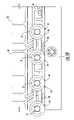
- FIG. 1is a top plan view of an embodiment of an article sorter, with upstream and downstream portions of the conveying surface removed to reveal internal details thereof;
- FIG. 2is a side elevation taken from the direction II-II in FIG. 1 ;
- FIG. 3is the same view as FIG. 2 with the side member removed to reveal internal structure thereof;
- FIG. 4is a bottom plan view taken from the direction IV-IV in FIG. 2 ;
- FIG. 5is a side elevation of the drive assembly driving the web
- FIG. 5 ais an enlargement of a portion of the drive assembly in FIG. 5 to show greater detail thereof;
- FIG. 6is a side elevation of a sprocket
- FIG. 7is an end elevation of the sprocket in FIG. 6 ;
- FIG. 8is a perspective view of a sprocket core
- FIG. 9is a side elevation of the sprocket core in FIG. 8 ;
- FIG. 10is a side elevation of a wheel assembly
- FIG. 11is a top plan view of a diverter switch assembly
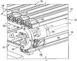
- FIG. 12is a perspective view of an alternative embodiment of an article sorter with a portion of the conveying surface removed to reveal internal details thereof;
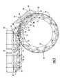
- FIG. 13is a side elevation of the article sorter in FIG. 12 ;
- FIG. 14is an perspective view of the lateral end of a slat in FIG. 12 illustrating a wheel assembly
- FIG. 15is a sectional view of a slat and pusher shoe in the embodiment of FIG. 12 .
- an article sorter 20is made up of an endless web 22 that is moveably supported by a frame assembly 23 ( FIG. 1 ).
- Web 22is made up of a plurality of laterally elongated slats 24 .
- An upper portion of web 22defines a conveying surface 26 moving in a longitudinal direction.
- Each slat 24has an upper surface 28 and a lower surface 30 .
- Upper surface 28is generally flat, or planar, such that article sorter 20 is known as a flat-top sorter. It should be understood that considerable variation in the shape of upper surface 28 from a true plane can be accommodated without negating it being generally flat or planer.
- Article sorter 20additionally includes a plurality of pusher shoes 32 which travel with the web in the longitudinal direction and can be diverted laterally in order to displace an article traveling on conveying surface 26 .
- Pusher shoes 32travel along one or more slats and can be of any configuration known in the art. Examples of pusher shoes 32 are disclosed in commonly assigned U.S. Pat. Nos. 5,127,510; 6,814,216; and 6,860,383; and U.S. Patent Application Publication No. 2005/0023108, the disclosures of which are hereby collectively incorporated herein by reference. Also, a lateral stabilizer 33 is defined between each pusher shoe 32 and slat 24 as described in the preceding patents.
- a divert switch assembly 80selectively diverts one or more pusher shoes 32 to a diverting rail 82 to divert the pusher shoe(s) from a non-diverted state, represented by lateral portion 50 of the conveying surface, to a diverted state, represented by lateral portion 52 of the conveying surface.
- This lateral movement of the pusher shoe(s)displaces an article, such as to a take-away spur (not shown), for sortation.
- Diverted pusher shoesare returned to a non-diverted state by a return rail 84 .
- article sorter 20is shown with a single divert switch assembly and diverting rail to provide the ability to divert an article to a single spur. However, multiple such divert switch and diverting rail combinations can be provided for article sorter 20 to allow sortation to multiple spurs.
- Wheel assembly 34includes a series of wheels 36 and links 38 ( FIG. 10 ). In the illustrated embodiment, two wheels are mounted to each end of each slat 24 and adjacent wheels of adjacent slats are joined by links 38 . Links 38 pivot about the axles 37 of the joined wheels to accommodate rotation between slats as they move around the ends of the web, as illustrated in FIGS. 5 and 5 a .
- Wheels 36are rotatably mounted to their respective slats by the fixed positioning of their respective axle 37 in an opening 39 in their slat. The axle may be fixed to the slat by press-fit, by fasteners, or the like. Other arrangements for interconnecting and supporting slats 24 , such as chains, are known in the art and may be used without deviating from the spirit of the present invention.
- Web 22is driven by a drive assembly 40 .
- Drive assembly 40includes at least one sprocket 42 , although two are used in the illustrated embodiment, and an electric motor 44 for rotating the sprocket(s).
- Motor 44may be in the form of a motorized roller in which the motor windings are internal to the roller and drive an outer shell 46 to which the sprocket(s) are attached.
- motorized rollersare well known in the art and come in various configurations, including alternating current, direct current, gear driven, direct driven, and the like.
- motor 44is a direct driven motorized roller having a 110 millimeter diameter outer shell 46 and a motor that is operated at 48 volts direct current.
- sprocket(s) 42may be shaft mounted and driven by an external motor rotating the shaft.
- the use of an external motormay be especially effective for longer conveying surfaces, such as ones which provide sortation to multiple spurs because it is capable of a wide range of output power.
- Each sprocketis positioned laterally between lateral portion 50 of conveying surface 26 , where non-diverted pusher shoes are located, and lateral portion 52 of the conveying surface, where diverted pusher shoes are located ( FIG. 1 ).
- This placement of sprocket(s) 42avoids interference with the pusher shoes while allowing the pusher shoes to be closer to the lateral edge of the conveying surface than if the sprocket(s) were to be located at extreme ends of shell 46 . This reduces the overall width of the conveying surface without restricting the article conveying area and ensures a more reliable divert by providing guidance of the article until it is essentially fully off of the conveying surface.
- Each sprocket 42has portions 54 that engage a slat in order to propel the web.
- Portions 54are made from an impact-absorbing material. This has the effect of significantly reducing noise generated by the driving of the web.
- the material of portions 54is a polymeric material, specifically polyurethane. Other impact absorbing material may be used.
- Web-engaging portions 54are provided in the illustrated embodiment by a series of bands, such as O-rings 58 , that are stretched across the face 55 of a core 57 .
- O-rings 58are stretched around pins 60 that protrude laterally from opposite sides of core 57 . This divides each O-ring into a first lobe 62 and a second lobe 64 stretched across the face 55 of core 57 .
- first lobe 62When viewed from the side, as illustrated in FIG. 6 , first lobe 62 is a greater distance from the center of rotation of core 57 than is second lobe 64 .
- First lobe 62is positioned in this manner by a first land 66 and second lobe 64 is positioned in this manner by a second land 68 , with first land 66 being elevated with respect to the second land.
- First lobe 62is also supported by a first adjacent surface 70 , extending perpendicular to first land 66 .
- Second lobe 64is also supported by a second adjacent surface 71 extending perpendicular to second land 68 .
- first lobe 62both supports and propels a slat 24 while second lobe 64 supports the slat.
- Each slat 24includes a first protrusion 72 and a second protrusion 74 defined in lower surface 30 .
- First and second lobes 62 , 64support and propel the slat by acting upon protrusions 72 and 74 .
- protrusions 72 , 74also define openings 39 for mounting of wheels 36 .
- each protrusion 72 , 74is cradled between a slat-engaging portion 54 of first lobe 62 of one O-ring 58 and a slat-engaging portion 54 of second lobe 64 of an adjacent O-ring.
- the slat-engaging portion 54 of first lobe 62engages higher on the protrusion to ensure that rotational force of the sprocket is transferred to the slat and, hence, to the web.
- urethane O-ringshave several advantages.
- the core of sprocket 42can be made of a more durable material, such as steel, aluminum, or the like, while still providing an impact absorbent interface to the slats.
- the O-ringscan be readily assembled and readily replaced for maintenance purposes. Also, this configuration is more economical than making the entire sprocket from urethane. O-rings are less expensive than an entire urethane sprocket.
- An end of web 22 opposite drive assembly 40includes an idler pulley assembly 76 .
- Idler pulley assembly 76includes a pair of pulleys 75 rotatably mounted by a shaft 77 .
- a take-up assembly 78is provided to idler pulley assembly 76 to remove any slack from the web and accommodate expansion and contraction of the web, such as due to temperature.
- take-up assembly 78includes a spring-biasing member, as best illustrated in FIG. 2 .
- Transition members 92provide transition from a feed conveyor (not shown) feeding articles to conveying surface 26 and between conveying surface 26 and a take-away conveyor (not shown) taking away articles exiting the end of conveying surface 26 .
- Diverting switch assembly 80includes an upstream facing divert arm 86 and a rotary solenoid 88 for selectively rotating arm 86 between a divert position and a non-divert position ( FIG. 11 ).
- the divert armIn the divert position illustrated in FIG. 11 , the divert arm intercepts the pin of a diverting pin and bearing assembly 90 extending beneath the associated pusher shoe and directs the pin and bearing assembly to diverting rail 82 .
- the divert armis retracted and allows the pin and bearing assembly 90 to continue along in a longitudinal direction.
- An advantage of such a divert switch assemblyis that rotary solenoid 88 can be controlled to move arm 86 to a divert position before the diverting pin and bearing assembly of the prior pusher shoe has fully cleared the divert switch assembly. This increases the speed of the divert cycle. A faster divert speed cycle allows the length of slats 24 in the direction of movement of web 22 to be shorter without sacrificing speed of the conveying surface. It should be understood that other types of divert switch assemblies can be used such as vertical diverters of the type disclosed in commonly assigned U.S. Pat. No. 5,038,912 or magnetically actuated diverters of the type disclosed in commonly assigned U.S. Pat. No. 6,615,972, the disclosures of which are both incorporated herein by reference.
- An alternative embodiment of an article sorter, designated 120is made up of an endless web 122 that is moveably supported by a frame assembly 123 ( FIGS. 12 through 15 .).
- Web 122is made up of a plurality of laterally elongated slats 124 .
- An upper portion of web 122defines a conveying surface 126 moving in a longitudinal direction.
- Each slat 124may have an upper surface 128 and a lower surface 130 .
- Upper surface 128is generally flat, or planar, such that article sorter 120 is known as a flat-top sorter. It should be understood that considerable variation in the shape of upper surface 128 from a true plane can be accommodated without negating it being generally flat or planer.
- Article sorter 120additionally includes a plurality of pusher shoes 132 which travel with the web in the longitudinal direction and can be diverted laterally in order to displace an article traveling on conveying surface 126 .
- Pusher shoes 132travel along one or more slats and can be of any configuration known in the art. Examples of pusher shoes 132 are disclosed in commonly assigned U.S. Pat. Nos. 5,127,510; 6,814,216; and 6,860,383; and U.S. Patent Application Publication No. 2005/0023108, the disclosures of which are hereby collectively incorporated herein by reference. Also, a lateral stabilizer 133 is defined between each pusher shoe 132 and slat 124 as described in the preceding patents.
- Frame assembly 123includes a track assembly 125 that supports web 122 for movement throughout its endless path.
- Track assembly 125includes an upper track portion 125 a that supports the upper portion of web 122 that defines the conveying surface.
- Track assembly 125further includes an end track portion 125 b that supports web 122 as it transitions from the conveying surface to a lower return portion of the web.
- track assembly 125is illustrated for supporting the web at one lateral end of the slats, it should be understood that another track assembly is provided on the opposite lateral side of the frame assembly to support the web at the opposite lateral end of the slats.
- Web 122is propelled by a drive assembly 140 which engages the web at end track portion 125 b .
- Drive assembly 140includes at least one sprocket 142 , although two are used in the illustrated embodiment, and an electric motor 144 for rotating the sprocket(s).
- motor 144drives a shaft 145 which rotatably supports sprocket(s) 142 . Connection between the motor and shaft may be by cog belt and sheaves, direct coupling, or the like.
- the motoris electrically actuated by a variable frequency drive which allows conveying surface 126 to be driven within a range of speeds. However, fixed speed or other forms of variable speed drives may be used.
- the motormay be in the form of a motorized roller in which the motor windings are internal to the roller and drive an outer shell to which the sprocket(s) are attached.
- motorized rollersare well known in the art and come in various configurations including alternating current, direct current, gear driven, direct driven, and the like.
- Each sprocket 142may be positioned laterally between a lateral portion 150 of conveying surface 126 , where non-diverted pusher shoes are located, and a lateral portion of the conveying surface (not shown), opposite to portion 150 , where diverted pusher shoes are located.
- This placement of sprocket(s) 142avoids interference with the pusher shoes while allowing the pusher shoes to be closer to the lateral edge of the conveying surface at the end of the divert than if the sprocket(s) were to be located at extreme ends of shaft 145 . This reduces the overall width of the conveying surface without restricting the article conveying area and ensures a more reliable divert by providing guidance of the article until it is essentially fully off of the conveying surface.
- Web 122may be supported on track assembly 125 by a wheel assembly 134 .
- Wheel assembly 134includes a series of wheels 136 and links 138 ( FIG. 10 ). In the illustrated embodiment, two wheels are mounted to each end of each slat 124 and adjacent slats are joined by links 138 .
- Links 138may pivot about bushings 135 which may also rotatably support a wheel 136 , all of which may be retained by a fastener 137 to accommodate rotation between slats as they move around the ends of the web, as illustrated in FIGS. 5 and 5 a .
- Fastener 137engages an opening 139 in the slat, such as by threads, press fit, or the like.
- the link and wheelmay be rotatably mounted on a common axle, by separate axles, or the like.
- the axlemay be fixed to the slat by press-fit, by fasteners, or the like.
- Other arrangements for interconnecting and supporting slats 24such as chains, links, or the like, are known in the art and may also be used.
- Sprocket(s) 142 and slats 124have engaging surface portions defined between the sprocket(s) and the slats that propel the web.
- These complementary surface portionsmay include an extension 194 of the sprocket which engages a depression, or slot, 195 of the slat, although the extension could be on the slat and the slot on the sprocket.
- Extension 194 and slot 195may have generally the same, but complementary, surface configurations.
- extension 194is configured as a gear tooth having sloped leading surface 196 a and sloped trailing surface 196 b .
- Leading surface 196 ahas a slope, such as approximately 15 degrees, that is steeper than trailing surface 196 b to impart a propelling force to the slat, but is sloped to allow smooth engagement with the slat according to gear design parameters.
- slats 124may be made of metal, such as extruded aluminum.
- extensions 194are made from an impact-absorbing material, such as a polymeric material. Examples of such material include polyurethane, nylon, Delran, and others, which are known to the skilled artisan. However, extensions may be made of other materials, including metals, and the like.
- the entire sprocket 142 including extensions 194may be formed as a unitary piece from one material. Alternatively, extensions 194 may be mounted as inserts in a hub of sprocket 142 that may thus be made from a different material. This would allow the hub to be made from a material, such as metal, that may be stronger and less costly than the material of the extensions. Also, this may allow worn or broken extensions to be replaced without the necessity to replace the entire sprocket.
- each pusher shoe 132may include a pin 198 for diverting of the pusher shoe to a diverting rail by a diverter switch and a bearing 199 for engagement of the diagonal diverting rail (not shown in FIG. 15 ) to laterally propel the pusher shoe to divert an article.
- Pusher shoe 132may include a fastener 200 that is an extension of guide pin 198 and which rotatably supports bearing 199 .
- the upper end of fastener 200is allowed to extend into slot 195 . This may reduce the vertical footprint of the pusher shoe and slat.
- FIG. 13it can be seen how the slats may be guided around the driven end of the web by the combination of sprocket(s) 142 and track assembly 125 .
- a slat 124supported by its wheels 136 on track assembly 125 , approaches the transition from the planar upper track portion 125 a to the curved end track portion 125 b , the slat is in the position illustrated as “A” in FIG. 13 .
- one extension 194 of sprocket 142is entering slot 195 . It can be seen that the extension has not yet fully entered the slot and that there is a space between the end of the extension and the bottom of the slot.
- Track assembly 125may include one or more bottom track sections 125 c to guide the return portion of the web. It may also include another curved end track portion (not shown) that is opposite to the driven end of the web. In this manner, the track assembly may be a generally continuous track to guide motion of the web throughout its endless travel. While bottom section 125 c is shown guiding the web from above as the web comes out of engagement with the sprocket, it may include a portion that supports the web from below against the force of gravity. The bottom track section may also include one or more sections to modify the motion of the lower run of the web including a take-up assembly, if desired.
Landscapes
- Engineering & Computer Science (AREA)
- Mechanical Engineering (AREA)
- Discharge Of Articles From Conveyors (AREA)
Abstract
Description
Claims (39)
Priority Applications (1)
| Application Number | Priority Date | Filing Date | Title |
|---|---|---|---|
| US11/947,319US7562761B2 (en) | 2006-04-26 | 2007-11-29 | Slat driven positive displacement sorter |
Applications Claiming Priority (3)
| Application Number | Priority Date | Filing Date | Title |
|---|---|---|---|
| US74566806P | 2006-04-26 | 2006-04-26 | |
| US11/738,573US20080035450A1 (en) | 2006-04-26 | 2007-04-23 | Slat driven positive displacement sorter |
| US11/947,319US7562761B2 (en) | 2006-04-26 | 2007-11-29 | Slat driven positive displacement sorter |
Related Parent Applications (1)
| Application Number | Title | Priority Date | Filing Date |
|---|---|---|---|
| US11/738,573Continuation-In-PartUS20080035450A1 (en) | 2006-04-26 | 2007-04-23 | Slat driven positive displacement sorter |
Publications (2)
| Publication Number | Publication Date |
|---|---|
| US20080116036A1 US20080116036A1 (en) | 2008-05-22 |
| US7562761B2true US7562761B2 (en) | 2009-07-21 |
Family
ID=46329873
Family Applications (1)
| Application Number | Title | Priority Date | Filing Date |
|---|---|---|---|
| US11/947,319Expired - Fee RelatedUS7562761B2 (en) | 2006-04-26 | 2007-11-29 | Slat driven positive displacement sorter |
Country Status (1)
| Country | Link |
|---|---|
| US (1) | US7562761B2 (en) |
Cited By (22)
| Publication number | Priority date | Publication date | Assignee | Title |
|---|---|---|---|---|
| US20100300835A1 (en)* | 2009-05-26 | 2010-12-02 | Dematic Corp. | Reducing drag on the web of a positive displacement sorter |
| EP2404851A1 (en)* | 2010-07-07 | 2012-01-11 | Daifuku Co., Ltd. | Article sorting device |
| WO2012026998A1 (en)* | 2010-08-27 | 2012-03-01 | Dematic Corp. | Positive displacement sorter |
| US20130161154A1 (en)* | 2011-12-23 | 2013-06-27 | Dematic Corp. | Sorter slat attachment |
| US9409716B2 (en) | 2014-06-13 | 2016-08-09 | Bastian Solutions, Llc | Cross belt slat sorter |
| US10532894B2 (en) | 2017-03-10 | 2020-01-14 | Regal Beloit America, Inc. | Modular transfer units, systems, and methods |
| US10640303B2 (en) | 2017-11-22 | 2020-05-05 | Regal Beloit America, Inc. | Modular sortation units, systems, and methods |
| US10864406B2 (en) | 2016-08-27 | 2020-12-15 | Peloton Interactive, Inc. | Exercise system and method |
| US10898760B2 (en) | 2017-12-14 | 2021-01-26 | Peloton Interactive, Inc. | Coordinating workouts across remote exercise machines |
| US10974094B2 (en) | 2016-08-27 | 2021-04-13 | Peloton Interactive, Inc. | Exercise system and method |
| US11081224B2 (en) | 2012-07-31 | 2021-08-03 | Peloton Interactive, Inc. | Exercise system and method |
| US11219799B2 (en) | 2016-08-27 | 2022-01-11 | Peloton Interactive, Inc. | Exercise system and method |
| US11235356B2 (en) | 2017-03-08 | 2022-02-01 | Regal Beloit America, Inc. | Package sorting transfer modules and systems and methods therefor |
| US11298591B2 (en) | 2016-08-27 | 2022-04-12 | Peloton Interactive, Inc. | Exercise machine controls |
| US11311791B2 (en) | 2016-08-27 | 2022-04-26 | Peloton Interactive, Inc. | Exercise system and method |
| US11338190B2 (en) | 2017-11-12 | 2022-05-24 | Peloton Interactive, Inc. | User interface with segmented timeline |
| DE102021113886A1 (en) | 2021-05-28 | 2022-12-01 | Dematic Gmbh | Sorting system and a method for its operation |
| US11610664B2 (en) | 2012-07-31 | 2023-03-21 | Peloton Interactive, Inc. | Exercise system and method |
| US20230219764A1 (en)* | 2022-01-07 | 2023-07-13 | Carbotech International | Plank positioning mechanism |
| US20240327127A1 (en)* | 2023-03-31 | 2024-10-03 | Interroll Holding Ag | Transfer Device |
| US12214260B2 (en) | 2016-08-27 | 2025-02-04 | Peloton Interactive, Inc. | Exercise machine controls |
| USD1087109S1 (en) | 2017-11-12 | 2025-08-05 | Peloton Interactive, Inc. | Display screen or portion thereof with a graphical user interface |
Families Citing this family (4)
| Publication number | Priority date | Publication date | Assignee | Title |
|---|---|---|---|---|
| NL1036169C2 (en)* | 2008-11-07 | 2010-05-10 | Vanderlande Ind Nederland | DEVICE FOR SORTING PRODUCTS. |
| JP6573921B2 (en)* | 2017-01-25 | 2019-09-11 | 株式会社椿本チエイン | Chain and chain conveyor |
| CN112551096A (en)* | 2020-12-24 | 2021-03-26 | 永清霍尔茨门业有限公司 | Efficient steering feeding device |
| CN115676331B (en)* | 2022-11-17 | 2024-12-10 | 英特诺物流机械(苏州)有限公司 | Conveyors and conveying systems |
Citations (8)
| Publication number | Priority date | Publication date | Assignee | Title |
|---|---|---|---|---|
| US5127510A (en)* | 1990-10-31 | 1992-07-07 | Rapistan Demag Corporation | Modular diverter shoe and slat construction |
| US5131522A (en)* | 1990-03-29 | 1992-07-21 | Daifuku Co., Ltd. | Transfer apparatus |
| US5217103A (en)* | 1991-01-15 | 1993-06-08 | Norbert Umlauf | Conveyor |
| US5590758A (en)* | 1995-06-06 | 1997-01-07 | Western Atlas Inc. | Slat sorter |
| US6705452B2 (en)* | 2002-05-13 | 2004-03-16 | Laitram, L.L.C. | Article-diverting conveyor belt and modules |
| US6814216B2 (en)* | 2000-09-28 | 2004-11-09 | Rapistan Systems Advertising Corp. | Positive displacement shoe and slat sorter apparatus and method |
| US6860383B2 (en)* | 2002-03-07 | 2005-03-01 | Rapistan Systems Advertising Corp. | Positive displacement sorter |
| US7090071B2 (en)* | 2004-02-12 | 2006-08-15 | Daifuku Co., Ltd. | Conveyor system |
- 2007
- 2007-11-29USUS11/947,319patent/US7562761B2/ennot_activeExpired - Fee Related
Patent Citations (11)
| Publication number | Priority date | Publication date | Assignee | Title |
|---|---|---|---|---|
| US5131522A (en)* | 1990-03-29 | 1992-07-21 | Daifuku Co., Ltd. | Transfer apparatus |
| US5127510A (en)* | 1990-10-31 | 1992-07-07 | Rapistan Demag Corporation | Modular diverter shoe and slat construction |
| US5217103A (en)* | 1991-01-15 | 1993-06-08 | Norbert Umlauf | Conveyor |
| US5590758A (en)* | 1995-06-06 | 1997-01-07 | Western Atlas Inc. | Slat sorter |
| US6814216B2 (en)* | 2000-09-28 | 2004-11-09 | Rapistan Systems Advertising Corp. | Positive displacement shoe and slat sorter apparatus and method |
| US6866136B2 (en)* | 2000-09-28 | 2005-03-15 | Rapistan Systems Advertising Corp. | Positive displacement shoe and slat sorter apparatus and method |
| US7086519B2 (en)* | 2000-09-28 | 2006-08-08 | Dematic Corp. | Positive displacement shoe and slat sorter apparatus and method |
| US6860383B2 (en)* | 2002-03-07 | 2005-03-01 | Rapistan Systems Advertising Corp. | Positive displacement sorter |
| US7117988B2 (en)* | 2002-03-07 | 2006-10-10 | Dematic Corp. | Positive displacement sorter |
| US6705452B2 (en)* | 2002-05-13 | 2004-03-16 | Laitram, L.L.C. | Article-diverting conveyor belt and modules |
| US7090071B2 (en)* | 2004-02-12 | 2006-08-15 | Daifuku Co., Ltd. | Conveyor system |
Non-Patent Citations (2)
| Title |
|---|
| International Search Report and Written Opinion from corresponding Patent Cooperation Treaty Application No. PCT/US07/85253, mailed Sep. 9, 2008. |
| Japan Patent 61-24500 dated Jul. 23, 1986, by Yoji Shirai of the Daifuku Kiko Co., Ltd. as submitted by the applicant on Nov. 29, 2007.* |
Cited By (53)
| Publication number | Priority date | Publication date | Assignee | Title |
|---|---|---|---|---|
| US20100300835A1 (en)* | 2009-05-26 | 2010-12-02 | Dematic Corp. | Reducing drag on the web of a positive displacement sorter |
| US8167116B2 (en)* | 2009-05-26 | 2012-05-01 | Dematic Corp. | Reducing drag on the web of a positive displacement sorter |
| EP2404851A1 (en)* | 2010-07-07 | 2012-01-11 | Daifuku Co., Ltd. | Article sorting device |
| US8459440B2 (en) | 2010-07-07 | 2013-06-11 | Daifuku Co., Ltd. | Article sorting device |
| WO2012026998A1 (en)* | 2010-08-27 | 2012-03-01 | Dematic Corp. | Positive displacement sorter |
| US8813943B2 (en) | 2010-08-27 | 2014-08-26 | Dematic Corp. | Positive displacement sorter |
| AU2011293870B2 (en)* | 2010-08-27 | 2015-10-29 | Dematic Corp. | Positive displacement sorter |
| US20130161154A1 (en)* | 2011-12-23 | 2013-06-27 | Dematic Corp. | Sorter slat attachment |
| US8820520B2 (en)* | 2011-12-23 | 2014-09-02 | Dematic Corp. | Sorter slat attachment |
| US8919542B2 (en) | 2011-12-23 | 2014-12-30 | Dematic Corp. | Sorter slat attachment |
| US11289185B2 (en) | 2012-07-31 | 2022-03-29 | Peloton Interactive, Inc. | Exercise system and method |
| US11081224B2 (en) | 2012-07-31 | 2021-08-03 | Peloton Interactive, Inc. | Exercise system and method |
| US11295849B2 (en) | 2012-07-31 | 2022-04-05 | Peloton Interactive, Inc. | Exercise system and method |
| US11640856B2 (en) | 2012-07-31 | 2023-05-02 | Peloton Interactive, Inc. | Exercise system and method |
| US11610664B2 (en) | 2012-07-31 | 2023-03-21 | Peloton Interactive, Inc. | Exercise system and method |
| US11915817B2 (en) | 2012-07-31 | 2024-02-27 | Peloton Interactive, Inc. | Exercise system and method |
| US11183288B2 (en) | 2012-07-31 | 2021-11-23 | Peloton Interactive, Inc. | Exercise system and method |
| US12249413B2 (en) | 2012-07-31 | 2025-03-11 | Peloton Interactive, Inc. | Exercise system and method |
| US11295850B2 (en) | 2012-07-31 | 2022-04-05 | Peloton Interactive, Inc. | Exercise system and method |
| US11139061B2 (en) | 2012-07-31 | 2021-10-05 | Peloton Interactive, Inc. | Exercise system and method |
| US11145398B2 (en) | 2012-07-31 | 2021-10-12 | Peloton Interactive, Inc. | Exercise system and method |
| US11145399B2 (en) | 2012-07-31 | 2021-10-12 | Peleton Interactive, Inc. | Exercise system and method |
| US11170886B2 (en) | 2012-07-31 | 2021-11-09 | Peloton Interactive, Inc. | Exercise system and method |
| US9809388B2 (en) | 2014-06-13 | 2017-11-07 | Bastian Solutions, Llc | Cross belt slat sorter |
| US9409716B2 (en) | 2014-06-13 | 2016-08-09 | Bastian Solutions, Llc | Cross belt slat sorter |
| US12214260B2 (en) | 2016-08-27 | 2025-02-04 | Peloton Interactive, Inc. | Exercise machine controls |
| US10974094B2 (en) | 2016-08-27 | 2021-04-13 | Peloton Interactive, Inc. | Exercise system and method |
| USD995554S1 (en) | 2016-08-27 | 2023-08-15 | Peloton Interactive, Inc. | Display screen or portion thereof with graphical user interface |
| US11219799B2 (en) | 2016-08-27 | 2022-01-11 | Peloton Interactive, Inc. | Exercise system and method |
| US12280293B2 (en) | 2016-08-27 | 2025-04-22 | Peloton Interactive, Inc. | Exercise system and method |
| US11298591B2 (en) | 2016-08-27 | 2022-04-12 | Peloton Interactive, Inc. | Exercise machine controls |
| US11311791B2 (en) | 2016-08-27 | 2022-04-26 | Peloton Interactive, Inc. | Exercise system and method |
| US12350552B2 (en) | 2016-08-27 | 2025-07-08 | Peloton Interactive, Inc. | Exercise system and method |
| US11400344B2 (en) | 2016-08-27 | 2022-08-02 | Peloton Interactive, Inc. | Exercise system and method |
| US12343595B2 (en) | 2016-08-27 | 2025-07-01 | Peloton Interactive, Inc. | Exercise system and method |
| US11617921B2 (en) | 2016-08-27 | 2023-04-04 | Peloton Interactive, Inc. | Exercise machine controls |
| US10864406B2 (en) | 2016-08-27 | 2020-12-15 | Peloton Interactive, Inc. | Exercise system and method |
| US11806761B2 (en) | 2017-03-08 | 2023-11-07 | Regal Beloit America, Inc. | Package sorting transfer modules and systems and methods therefor |
| US11235356B2 (en) | 2017-03-08 | 2022-02-01 | Regal Beloit America, Inc. | Package sorting transfer modules and systems and methods therefor |
| US10532894B2 (en) | 2017-03-10 | 2020-01-14 | Regal Beloit America, Inc. | Modular transfer units, systems, and methods |
| US11858752B2 (en) | 2017-03-10 | 2024-01-02 | Regal Beloit America, Inc. | Modular transfer units, systems, and methods |
| US11247849B2 (en) | 2017-03-10 | 2022-02-15 | Regal Beloit America, Inc. | Modular transfer units, systems, and methods |
| US11724891B2 (en) | 2017-03-10 | 2023-08-15 | Regal Beloit America, Inc. | Modular transfer units, systems, and methods |
| US11338190B2 (en) | 2017-11-12 | 2022-05-24 | Peloton Interactive, Inc. | User interface with segmented timeline |
| USD1087109S1 (en) | 2017-11-12 | 2025-08-05 | Peloton Interactive, Inc. | Display screen or portion thereof with a graphical user interface |
| US11130643B2 (en) | 2017-11-22 | 2021-09-28 | Regal Beloit America, Inc. | Modular sortation units, systems, and methods |
| US10640303B2 (en) | 2017-11-22 | 2020-05-05 | Regal Beloit America, Inc. | Modular sortation units, systems, and methods |
| US10898760B2 (en) | 2017-12-14 | 2021-01-26 | Peloton Interactive, Inc. | Coordinating workouts across remote exercise machines |
| DE102021113886A1 (en) | 2021-05-28 | 2022-12-01 | Dematic Gmbh | Sorting system and a method for its operation |
| WO2022248306A1 (en) | 2021-05-28 | 2022-12-01 | Dematic Gmbh | Sorting system and method for operating same |
| US20230219764A1 (en)* | 2022-01-07 | 2023-07-13 | Carbotech International | Plank positioning mechanism |
| US12269687B2 (en)* | 2022-01-07 | 2025-04-08 | Carbotech International | Plank positioning mechanism |
| US20240327127A1 (en)* | 2023-03-31 | 2024-10-03 | Interroll Holding Ag | Transfer Device |
Also Published As
| Publication number | Publication date |
|---|---|
| US20080116036A1 (en) | 2008-05-22 |
Similar Documents
| Publication | Publication Date | Title |
|---|---|---|
| US7562761B2 (en) | Slat driven positive displacement sorter | |
| US6612420B1 (en) | Device for transferring articles between oppositely running conveyors | |
| CA1277278C (en) | Storing installation, primarily for an endless conveyor belt travelling helically in a number of turns laid upon one another in a pile | |
| US6571937B1 (en) | Switch conveyor | |
| EP1962717B1 (en) | Conveyor switch | |
| US8561790B2 (en) | Belt drive conveyor with power tap off | |
| US6669001B1 (en) | Linear belt sorter and methods of using linear belt sorter | |
| CA2705515A1 (en) | Slat driven positive displacement sorter | |
| KR20120001727A (en) | Sorting conveyor | |
| GB1575327A (en) | Drive unit for an endless conveyor | |
| US11939171B2 (en) | Conveyor system and drive system for same | |
| US3627109A (en) | Conveyor construction | |
| EP1060111B1 (en) | Curved conveyor | |
| US20080035450A1 (en) | Slat driven positive displacement sorter | |
| US8701874B2 (en) | Conveyor | |
| US4825999A (en) | Chain drive apparatus | |
| US6237755B1 (en) | Chain drive with adjustable friction | |
| US6659897B2 (en) | Chain drive assembly | |
| US3714903A (en) | Takeup apparatus for truck tow conveyor system | |
| AU651377B2 (en) | Improvements in or relating to conveyors | |
| US20130327614A1 (en) | Conveyor driven by a cam | |
| FI77195B (en) | LARVBANDSANORDNING FOER TERRAENGFORDON ELLER LIKNANDE. | |
| MXPA00006829A (en) | Curved conveyor |
Legal Events
| Date | Code | Title | Description |
|---|---|---|---|
| AS | Assignment | Owner name:DEMATIC CORP., MICHIGAN Free format text:ASSIGNMENT OF ASSIGNORS INTEREST;ASSIGNORS:TASMA, RYAN D.;COTTER, DAVID H.;HAAN, TED W.;REEL/FRAME:020475/0133;SIGNING DATES FROM 20071130 TO 20080108 | |
| STCF | Information on status: patent grant | Free format text:PATENTED CASE | |
| AS | Assignment | Owner name:JPMORGAN CHASE BANK, N.A., AS ADMINISTRATIVE AGENT Free format text:SECURITY AGREEMENT;ASSIGNORS:DEMATIC CORP.;HK ACQUISITION, INC.;HK SYSTEMS, INC.;AND OTHERS;REEL/FRAME:025169/0001 Effective date:20100915 | |
| AS | Assignment | Owner name:IRISTA, INC., WISCONSIN Free format text:RELEASE BY SECURED PARTY;ASSIGNOR:JPMORGAN CHASE BANK, N.A., AS ADMINISTRATIVE AGENT;REEL/FRAME:026216/0959 Effective date:20110428 Owner name:HK HOLDINGS, INC., MICHIGAN Free format text:RELEASE BY SECURED PARTY;ASSIGNOR:JPMORGAN CHASE BANK, N.A., AS ADMINISTRATIVE AGENT;REEL/FRAME:026216/0959 Effective date:20110428 Owner name:HK SYSTEMS, INC., WISCONSIN Free format text:RELEASE BY SECURED PARTY;ASSIGNOR:JPMORGAN CHASE BANK, N.A., AS ADMINISTRATIVE AGENT;REEL/FRAME:026216/0959 Effective date:20110428 Owner name:HK ACQUISITION, INC., MICHIGAN Free format text:RELEASE BY SECURED PARTY;ASSIGNOR:JPMORGAN CHASE BANK, N.A., AS ADMINISTRATIVE AGENT;REEL/FRAME:026216/0959 Effective date:20110428 Owner name:DEMATIC CORP., MICHIGAN Free format text:RELEASE BY SECURED PARTY;ASSIGNOR:JPMORGAN CHASE BANK, N.A., AS ADMINISTRATIVE AGENT;REEL/FRAME:026216/0959 Effective date:20110428 | |
| AS | Assignment | Owner name:J.P. MORGAN EUROPE LIMITED, AS SECURITY AGENT, UNI Free format text:SECURITY AGREEMENT;ASSIGNOR:DEMATIC CORP.;REEL/FRAME:026376/0594 Effective date:20110428 | |
| FPAY | Fee payment | Year of fee payment:4 | |
| AS | Assignment | Owner name:CREDIT SUISSE AG, CAYMAN ISLANDS BRANCH, AS COLLAT Free format text:SECURITY AGREEMENT;ASSIGNOR:DEMATIC CORP.;REEL/FRAME:029556/0364 Effective date:20121228 | |
| AS | Assignment | Owner name:DEMATIC CORP., MICHIGAN Free format text:RELEASE BY SECURED PARTY;ASSIGNOR:J.P. MORGAN EUROPE LIMITED, AS SECURITY AGENT;REEL/FRAME:029558/0985 Effective date:20121228 | |
| AS | Assignment | Owner name:DEMATIC CORP., MICHIGAN Free format text:RELEASE BY SECURED PARTY;ASSIGNOR:CREDIT SUISSE AG, CAYMAN ISLANDS BRANCH, AS COLLATERAL AGENT;REEL/FRAME:040543/0005 Effective date:20161101 | |
| FPAY | Fee payment | Year of fee payment:8 | |
| FEPP | Fee payment procedure | Free format text:MAINTENANCE FEE REMINDER MAILED (ORIGINAL EVENT CODE: REM.); ENTITY STATUS OF PATENT OWNER: LARGE ENTITY | |
| LAPS | Lapse for failure to pay maintenance fees | Free format text:PATENT EXPIRED FOR FAILURE TO PAY MAINTENANCE FEES (ORIGINAL EVENT CODE: EXP.); ENTITY STATUS OF PATENT OWNER: LARGE ENTITY | |
| STCH | Information on status: patent discontinuation | Free format text:PATENT EXPIRED DUE TO NONPAYMENT OF MAINTENANCE FEES UNDER 37 CFR 1.362 | |
| FP | Lapsed due to failure to pay maintenance fee | Effective date:20210721 |