US7561895B1 - Reverse sectorization wireless communication - Google Patents
Reverse sectorization wireless communicationDownload PDFInfo
- Publication number
- US7561895B1 US7561895B1US09/658,241US65824100AUS7561895B1US 7561895 B1US7561895 B1US 7561895B1US 65824100 AUS65824100 AUS 65824100AUS 7561895 B1US7561895 B1US 7561895B1
- Authority
- US
- United States
- Prior art keywords
- antenna
- access point
- subscriber unit
- wireless communication
- communication system
- Prior art date
- Legal status (The legal status is an assumption and is not a legal conclusion. Google has not performed a legal analysis and makes no representation as to the accuracy of the status listed.)
- Expired - Lifetime, expires
Links
- 230000002441reversible effectEffects0.000titleclaimsabstractdescription16
- 238000004891communicationMethods0.000titleclaimsdescription137
- 230000005540biological transmissionEffects0.000claimsabstractdescription27
- 238000009826distributionMethods0.000claimsdescription150
- 238000000034methodMethods0.000claimsdescription18
- 230000003213activating effectEffects0.000claims1
- 230000011664signalingEffects0.000description8
- 238000010586diagramMethods0.000description6
- 239000007787solidSubstances0.000description6
- 238000007726management methodMethods0.000description5
- 230000007935neutral effectEffects0.000description5
- 230000008901benefitEffects0.000description4
- 238000005516engineering processMethods0.000description4
- 238000003860storageMethods0.000description4
- 230000033228biological regulationEffects0.000description3
- 238000010276constructionMethods0.000description3
- 238000013461designMethods0.000description3
- 230000003044adaptive effectEffects0.000description2
- WYTGDNHDOZPMIW-RCBQFDQVSA-NalstonineNatural productsC1=CC2=C3C=CC=CC3=NC2=C2N1C[C@H]1[C@H](C)OC=C(C(=O)OC)[C@H]1C2WYTGDNHDOZPMIW-RCBQFDQVSA-N0.000description2
- 238000006243chemical reactionMethods0.000description2
- 239000003795chemical substances by applicationSubstances0.000description2
- 230000005611electricityEffects0.000description2
- 239000013307optical fiberSubstances0.000description2
- 230000002093peripheral effectEffects0.000description2
- 230000008569processEffects0.000description2
- 238000012546transferMethods0.000description2
- RYGMFSIKBFXOCR-UHFFFAOYSA-NCopperChemical compound[Cu]RYGMFSIKBFXOCR-UHFFFAOYSA-N0.000description1
- 230000006978adaptationEffects0.000description1
- 230000001413cellular effectEffects0.000description1
- 150000001875compoundsChemical class0.000description1
- 229910052802copperInorganic materials0.000description1
- 239000010949copperSubstances0.000description1
- 238000013500data storageMethods0.000description1
- 230000001934delayEffects0.000description1
- 238000011161developmentMethods0.000description1
- 230000007613environmental effectEffects0.000description1
- 230000010354integrationEffects0.000description1
- 230000007774longtermEffects0.000description1
- 238000004519manufacturing processMethods0.000description1
- 239000002184metalSubstances0.000description1
- 229910052751metalInorganic materials0.000description1
- 238000003032molecular dockingMethods0.000description1
- 238000012544monitoring processMethods0.000description1
- 230000006855networkingEffects0.000description1
- 230000000737periodic effectEffects0.000description1
- 230000010287polarizationEffects0.000description1
- 229920001690polydopaminePolymers0.000description1
- 238000011084recoveryMethods0.000description1
- 230000009467reductionEffects0.000description1
- 230000001105regulatory effectEffects0.000description1
- 230000004044responseEffects0.000description1
- 230000000717retained effectEffects0.000description1
- 238000012216screeningMethods0.000description1
- 230000035945sensitivityEffects0.000description1
- 230000003595spectral effectEffects0.000description1
- 238000012360testing methodMethods0.000description1
- 238000010618wire wrapMethods0.000description1
Images


Classifications
- H—ELECTRICITY
- H04—ELECTRIC COMMUNICATION TECHNIQUE
- H04B—TRANSMISSION
- H04B7/00—Radio transmission systems, i.e. using radiation field
- H04B7/02—Diversity systems; Multi-antenna system, i.e. transmission or reception using multiple antennas
- H04B7/04—Diversity systems; Multi-antenna system, i.e. transmission or reception using multiple antennas using two or more spaced independent antennas
- H04B7/0491—Diversity systems; Multi-antenna system, i.e. transmission or reception using multiple antennas using two or more spaced independent antennas using two or more sectors, i.e. sector diversity
- H—ELECTRICITY
- H01—ELECTRIC ELEMENTS
- H01Q—ANTENNAS, i.e. RADIO AERIALS
- H01Q1/00—Details of, or arrangements associated with, antennas
- H01Q1/12—Supports; Mounting means
- H01Q1/1207—Supports; Mounting means for fastening a rigid aerial element
- H—ELECTRICITY
- H01—ELECTRIC ELEMENTS
- H01Q—ANTENNAS, i.e. RADIO AERIALS
- H01Q1/00—Details of, or arrangements associated with, antennas
- H01Q1/12—Supports; Mounting means
- H01Q1/1242—Rigid masts specially adapted for supporting an aerial
- H—ELECTRICITY
- H01—ELECTRIC ELEMENTS
- H01Q—ANTENNAS, i.e. RADIO AERIALS
- H01Q1/00—Details of, or arrangements associated with, antennas
- H01Q1/12—Supports; Mounting means
- H01Q1/22—Supports; Mounting means by structural association with other equipment or articles
- H01Q1/24—Supports; Mounting means by structural association with other equipment or articles with receiving set
- H01Q1/241—Supports; Mounting means by structural association with other equipment or articles with receiving set used in mobile communications, e.g. GSM
- H01Q1/246—Supports; Mounting means by structural association with other equipment or articles with receiving set used in mobile communications, e.g. GSM specially adapted for base stations
- H—ELECTRICITY
- H04—ELECTRIC COMMUNICATION TECHNIQUE
- H04W—WIRELESS COMMUNICATION NETWORKS
- H04W16/00—Network planning, e.g. coverage or traffic planning tools; Network deployment, e.g. resource partitioning or cells structures
- H04W16/24—Cell structures
- H—ELECTRICITY
- H04—ELECTRIC COMMUNICATION TECHNIQUE
- H04W—WIRELESS COMMUNICATION NETWORKS
- H04W84/00—Network topologies
- H04W84/02—Hierarchically pre-organised networks, e.g. paging networks, cellular networks, WLAN [Wireless Local Area Network] or WLL [Wireless Local Loop]
- H04W84/10—Small scale networks; Flat hierarchical networks
- H04W84/14—WLL [Wireless Local Loop]; RLL [Radio Local Loop]
- H—ELECTRICITY
- H04—ELECTRIC COMMUNICATION TECHNIQUE
- H04W—WIRELESS COMMUNICATION NETWORKS
- H04W88/00—Devices specially adapted for wireless communication networks, e.g. terminals, base stations or access point devices
- H04W88/02—Terminal devices
Definitions
- the present inventionrelates to wireless communication systems and the interface between wireless subscriber equipment and communication system access antennas.
- Wireless systemssuch as PCS and cellular systems, typically include a centralized mobile switching center (MSC) responsible for call routing, user location tracking, billing information, and connectivity with other communication systems.
- the MSCis connected to base station controllers (BSCs), each of which supports one or more base transceiver stations (BTSs).
- BSCsbase station controllers
- BTSsbase transceiver stations
- Each BTSsupports one or more cells or cell sectors based on the number and configuration of antennas supported by the BTS.
- a customercommunicates with the wireless system through a wireless unit, such as a radio telephone, when the telephone is within the coverage range of a cell.
- a wireless unitsuch as a radio telephone
- the MSCdetermines the destination and, if the destination is to another telephone within the wireless system, establishes a circuit-switched connection to the destination telephone. If the destination is outside of the wireless system, the MSC routes the call to a service provider for the outside destination.
- a key component in any wireless communication systemis the antenna forming the edge contact between wireless subscribers and the remaining system.
- each antennais designed to provide sectored or directional coverage over a portion of the region around the BTS.
- Each subscriber transceiversuch as a radio telephone, has an omnidirectional antenna.
- a wireless linkis established between the directional BTS antenna and the omnidirectional radio telephone antenna.
- Downlink informationis transmitted from the directional antenna into the sector and is received by the radio telephone.
- Uplink informationis transmitted in a uniform coverage area around the radio telephone and is received by the BTS directional antenna.
- omnidirectional antennasare often within the overlapping coverage area of multiple sectors.
- the omnidirectional broadcasts from telephonesmay interfere with transmissions to and from nearby telephones.
- telephoneshave no control over which directional antenna establishes the communication link. What is needed is to provide an improved interface between wireless subscriber units such as radio telephones and the point at which these units connect to a wireless communication system.
- the present inventionprovides an improved wireless communication system through reverse sectorization.
- subscriber unitsexhibit directionality and wireless system access points exhibit uniform coverage.
- a wireless communication systemincludes a plurality of access points. Each access point has at least one omnidirectional antenna forming a substantially uniform coverage area around the access point.
- the systemalso includes a plurality of subscriber units. Each subscriber unit has at least one directional antenna forming a directional coverage area. Subscriber units communicate with a particular access point through transmissions between the subscriber unit directional antenna and the omnidirectional antenna for the particular access point.
- the directional antennamay include a plurality of antenna patches or other antenna elements with the subscriber unit selecting at least one antenna patch as the directional antenna.
- the directional antennamay also be positioned to optimize transmissions between the subscriber unit and the particular access point.
- the communication systemincludes a routing network interconnecting the access points.
- the routing networkmay be implemented as a distributed network of distribution points.
- a distribution pointmay be located with an access point.
- an access pointmay be in wireless communication with the routing network through a backhaul antenna.
- the subscriber unitis a terminal network controller having at least one interface.
- Each interfaceprovides access to the wireless communication system for communication devices such as computers, computer networks, personal digital assistants, handsets, Internet appliances, entertainment devices, and the like.
- the terminal network controllermay include a routing switch routing information packets to and from the interfaces.
- the wireless communication systemalso includes access points having at least one directional antenna forming a coverage sector around a portion of the access point. Subscriber units with at least one omnidirectional antenna communicate with these access points. Hence, the wireless communication system implements both sectorization and reverse sectorization. At least one access point has both an omnidirectional antenna and a directional antenna. Transmissions from omnidirectional access antennas may be at a frequency different than transmission from directional access antennas.
- a method of wireless communicationis also provided. Downlink information is transmitted in a substantially uniform coverage area around each access point. The downlink information is received at a subscriber unit which transmits uplink information in a focused coverage area from the subscriber unit. The uplink information is received at one of the access points.
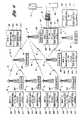
- FIG. 1is a schematic drawing illustrating a portion of a communication system according to an embodiment of the present invention
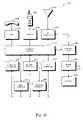
- FIG. 2is a block diagram of a distribution point according to an embodiment of the present invention.
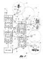
- FIG. 3is a schematic drawing illustrating an implementation of a communication system according to an embodiment of the present invention.
- FIG. 4is a schematic drawing illustrating an initial state for a communication system according to an embodiment of the present invention.
- FIG. 5is a schematic drawing illustrating the addition of a second access point to the communication system of FIG. 4 according to an embodiment of the present invention
- FIG. 6is a schematic drawing illustrating a hierarchical routing system using ATM/IP switches according to an embodiment of the present invention
- FIG. 7is a schematic drawing illustrating a network of distribution points routing packets based on forward equivalency classes.
- FIG. 8is a schematic drawing illustrating forward equivalency class updating to track a moving subscriber unit
- FIG. 9is an elevation view drawing of a pole mounted antenna system powered according to an embodiment of the present invention.
- FIG. 10is a schematic drawing of a street light control system with a power adapter according to an embodiment of the present invention.
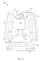
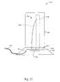
- FIG. 11is an elevation view drawing of an antenna system according to an embodiment of the present invention.
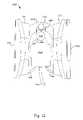
- FIG. 12is a plan view drawing of an antenna system having a single backhaul antenna according to an embodiment of the present invention.
- FIG. 13is a plan view drawing of an antenna system having two backhaul antennas according to an embodiment of the present invention.
- FIG. 14is a schematic drawing illustrating a prior art sectorized communication system
- FIG. 15is a schematic drawing illustrating reverse sectorization according to an embodiment of the present invention.
- FIG. 16is a block diagram of a terminal network controller according to an embodiment of the present invention.
- FIG. 17is a conceptualized drawing of a terminal network controller with integral antenna elements according to an embodiment of the present invention.
- FIG. 18is a block diagram of a system for determining a terminal network controller directional antenna according to an embodiment of the present invention.
- FIG. 19is a conceptual drawing of a terminal network controller having separate antenna and interface housings according to an embodiment of the present invention.
- FIG. 20is a conceptualized drawing of patch antennas constructed on a flexible printed circuit according to an embodiment of the present invention.
- FIG. 21is a conceptualized drawing of a rotatable subscriber directional antenna according to an embodiment of the present invention.
- FIG. 22is a conceptualized drawing of an additional embodiment for a subscriber directional antenna.
- a communication systemshown generally by 20 , includes a plurality of access points 22 which may be, for example, a local radio access point (LRAP).
- Each access point 22defines coverage area 24 such as, for example, a cell, covering a reception range of access point 22 .
- Coverage area 24may be formed from many independent sectors, as may result if access point 22 uses many directional antennas, or may be a single region resulting from the use of an omnidirectional antenna.
- Subscriber unit 26 within coverage area 24may establish two-way wireless link 28 with access point 22 .
- Subscriber unit 26may also establish wireline link 29 with access point 22 .
- Links 28 , 29may be symmetrical or asymmetrical.
- Subscriber unit 26may be fixed or non-fixed and, if non-fixed, may posses varying degrees of portability and mobility.
- Subscriber unit 26may be a mobile telephone, a computer, a video receiver, an audio receiver, a two-way video conferencing station, a video game, an information kiosk, a remote sensor, a remote actuator, or any other suitable communication device.
- Wireless link 28may be any form of electromagnetic signaling not confined to a wire or cable, including energy radiated by antenna as well as visible and invisible light.
- wireless link 28may be implemented by any access technology, including CDMA, TDMA, FDMA, OFDM, analog, and the like.
- Modulation techniquesthat may be used with the present invention include FSK, BPSK, QPSK, m-ary QAM, FM, AM, and the like. Further, the invention does not depend on modulation frequency or on the use of FDD or TDD.
- the access technology, frequency, and modulation method for establishing wireless link 28are based, in part, on local geography, local regulations, noise and distortion sources, other operating wireless systems, cost, or any other suitable parameter.
- Subscriber unit 26 and access point 22may establish wireless link 28 using a plurality of combinations of access technology, frequency, and modulation techniques.
- Information transmitted on links 28 , 29may represent voice, data, video, streaming audio, streaming video, or the like.
- Types of informationinclude speech, facsimile, computer data, entertainment and informational audio and video, video game data, telemetry information, security information, and the like. If the information occurs as a continuous stream, subscriber unit 26 breaks the information into packets prior to packet transmission and reassembles the information stream from packets after packet reception. Any type of information that exists in packets or that may be packetized can be used with the present invention.
- subscriber unit 26may be implemented as part of terminal network controller 30 accepting inputs from and providing outputs to information sources including voice equipment 32 , computing equipment 34 , telemetry equipment 36 , video equipment 38 , or any other suitable communication equipment.
- Inputs to terminal network controller 30may include serial data, parallel data, ISDN, standard telephone, xDSL, SR 1394, coaxial cable, twisted pair cable, optical fiber, or any other suitable communication protocol, method, or medium.
- a quality error bit rateis established for each subscriber unit 26 .
- This quality error bit ratemay be based on the location of subscriber unit 26 within communication system 20 , the class of service assigned to subscriber unit 26 , the grade of service assigned to subscriber unit 26 , the data or transmission rate of service assigned to subscriber unit 26 , or any other suitable parameter.
- the quality error bit ratemay be modified while subscriber unit 26 is within communication system 20 to reflect changing conditions such as noise, demand, connectivity, or any other suitable parameter.
- Applications providing services to subscriber unit 26may adjust these services based on the quality error bit rate. For example, an application providing streaming audio and video may reduce the frame update rate as noise increases, guaranteeing successful transmission at a lower information rate.
- the information ratemay be further reduced to provide only still pictures and audio if conditions continue to worsen.
- the information ratemay also be automatically changed if subscriber unit 26 moves between coverage areas 24 with differing transmission capabilities or loads.
- Control of the information ratemay be achieved by having subscriber unit 26 monitor a signaling channel transmitted by access point 22 for each coverage area 24 .
- This signaling channelinforms subscriber unit 26 when to transmit information, how much information to transmit, the information transmission rate, and the like.
- the signaling channelmay be controlled by a central supervisor, described below.
- bandwidth on communication link 28is only consumed when packets containing information are transmitted.
- each subscriber unit 26surrenders bandwidth on communication link 28 when not sending or receiving an information packet.
- Packets to be transmittedare queued based on order of arrival, priority, a combination of arrival order and priority, or the like.
- Subscriber unit 26monitors a signaling channel transmitted by access point 22 for each coverage area 24 . Subscriber unit 26 only consumes bandwidth when instructed to transmit by the signaling channel or when receiving packets.
- Each access point 22communicates with at least one distribution point 40 .
- Distribution point 40contains both routing and switching functionality.
- Access point 22may be in contact with one or more radio access distribution points 40 over radio link 42 , may be wired or cabled to distribution point 40 through wireline link 44 , or may be packaged with distribution point 40 .
- Access point 22may also be transformed into distribution point 40 , permitting access point 22 to route traffic that neither originated nor terminated with any of its serviced subscriber units 26 .
- Distribution point 40is in communication with at least one additional distribution point 40 , the collection of interconnected distribution points forming a network of distribution points, shown generally by 41 . Two distribution points may be connected by radio link 46 or wireline link 48 .
- Distribution points 40may route packets within distribution point network 41 under a variety of protocols such as ATM, TCP/IP, 802.x, or the like.
- distribution point 40includes an ATM/IP switch.
- Distribution point 40then operates at both the IP routing and ATM switching layers or, in terms of the Open Systems Interconnection (OSI) standard, at both the network layer and the data link layer.
- OSIOpen Systems Interconnection
- the IP layeroperates with a link-state protocol such as the open shortest path first (OSPF), quality OSPF (Q-OSPF), or internal gateway routing protocol (IGRP) and its derivatives.
- the IP layeroperates as a single autonomous system (AS) within the IP frame of reference.
- Each system 20will be allocated a unique and unambiguous AS number for system management.
- IP addresses for system 20will use a private IP address space that cannot be routed within public systems such as the Internet.
- Subscriber units 26 within system 20may be permitted access to the private IP address space or may be excluded from the private IP address space.
- NATnetwork address translator
- the ATM layeroperates with the private network node interface (PNNI) routing protocol.
- AESAsATM end system addresses
- AESAsATM end system addresses
- the ATM networkcarries voice traffic and may carry data. Through PNNI, the ATM/IP switch participates in switched or signaled virtual connections (SVCs). When subscriber unit 26 within system 20 requires voice connectivity, it signals such a request, which is serviced by distribution point 40 receiving that request.
- SVCsswitched or signaled virtual connections
- the IP network coresiding with the ATM networkis used for delay insensitive data applications required by subscriber units 26 .
- the IP networkis also used for all network management, including management of ATM/IP switches, subscriber units 26 , gear associated with distribution points 40 , and any other suitable network component. This includes functions such as alarming, monitoring, recovery systems, and the like. While described in the context of a wireless network application, it is readily apparent that ATM/IP routing as described herein may be applied to wireline and mixed wireline-wireless systems as well.
- Each distribution point 40receives an information packet from either another distribution point 40 , from subscriber unit 26 in communication with distribution point 40 through access point 22 , or from an external communication system. If distribution point 40 determines the information packet is destined for subscriber unit 26 within coverage area 24 of access point 22 in communication with distribution point 40 , distribution point 40 forwards the packet to access point 22 forming coverage area 24 containing destination subscriber unit 26 . If distribution point 40 determines the information packet is destined for subscriber unit 26 in coverage area 24 formed by access point 22 in communication with a different distribution point 40 , distribution point 40 forwards the packet to one of distribution points 40 in communication with distribution point 40 . Hence, no central MSC is required for routing. Distributed routing removes delays caused by central switching, increases the robustness of the communication system 20 , increases network efficiency, and permits simplified expansion or reduction of communication system 20 by automatically adding or removing distribution points 40 .
- a third optionis that distribution point 40 determines that the information packet is destined for a destination not part of communication system 20 .
- Special distribution pointssuch as gateway 50 , provide a bridge to additional communication systems 52 including wireless and wireline telecommunication systems, video distribution systems, computer network systems such as the Internet, packet systems, frame systems, ATM systems, IP systems, private networks, and any other suitable communication or information system. If distribution point 40 determines the information packet is destined for delivery outside of communication system 20 , distribution point 40 forwards the packet to one of distribution points 40 in communication with gateway 50 .
- communication system 20includes communication system interface device 54 operative to format information contained in the information packet to pass through telecommunication system 52 .
- Communication system interface device 54may be incorporated into gateway 50 or may be a separate component of communication system 20 .
- Distribution point 40receives at least one information packet from the telecommunication system interface device 54 and determines if the at least one information packet destination is to subscriber unit 26 within coverage area 24 of access point 22 in communication with distribution point 40 .
- Distribution point 40forwards the at least one information packet to access point 22 defining coverage area 24 containing subscriber unit 26 if the information packet destination is to subscriber unit 26 within coverage area 24 of access point 22 in communication with distribution point 40 and forwards the at least one information packet to one of the additional distribution points 40 in communication with distribution point 40 otherwise.
- Supervisor 56tracks the locations of subscriber units 26 within communication system 20 , identifying with which distribution point 40 each subscriber unit 26 is currently communicating. Supervisor 56 manages transmission priorities based on parameters including load, information type, service requests, location, grade of service, information transfer rates, or any other suitable parameter. Supervisor 56 may also serve as a collection point for alarms and performance measuring of communication system 20 . Supervisor 56 may further include or interface with billing and authentication services.
- supervisor 56also assigns an address to each distribution point 40 as distribution point 40 is added to communication system 20 .
- Supervisor 56provides each distribution point 40 with a logical address and a listing indicating to which additional distribution point 40 in communication with distribution point 40 information packets should be forwarded for each possible destination distribution point 40 .
- the listingmay be based on maintaining a minimum quality of service in the path through distribution point network 41 to the destination distribution point 40 .
- Supervisor 56periodically assesses the performance of network 41 by sending test messages. Reports may also be generated by distribution points 40 attempting to communicate with target addresses.
- Supervisor 56is shown in FIG. 1 as a separate component individually connected to each distribution point 40 .
- communication between supervisor 56 and distribution points 40may be through radio links 46 and wireline links 48 .
- Supervisor 56may be one or more separate components of communication system 20 , may be incorporated into one of distribution points 40 , or may be distributed amongst multiple distribution points 40 .
- a distribution pointmay be automatically added to or removed from distribution point network 41 .
- new distribution point 40transmits a signature signal.
- Existing distribution points 40 within range of new distribution point 40receive the signal and report it to supervisor 56 .
- Supervisor 56determines if new distribution point 40 will be added to network 41 . If so, supervisor 56 assigns new distribution point 40 a routing address and informs network 41 as needed.
- Each existing distribution point 40 in distribution point network 41is provided with an indication as to which distribution point 40 in communication with existing distribution point 40 each information packet having a destination address specifying the new distribution point 40 is to be forwarded. If a distribution point 40 is removed from network 41 , remaining distribution points 41 report the absence of removed distribution point 40 to supervisor 56 . Supervisor 56 then informs network 41 as needed.
- each subscriber unit 26is autonomously registered with communication system 20 when subscriber unit 26 first enters coverage area 24 within communication system 20 .
- Each subscriber unit 26maintains registration as subscriber unit 26 moves from one coverage area 24 into another coverage area 24 within communication system 20 and is autonomously deregistered when subscriber unit 26 leaves communication system 20 .
- each access point 22periodically reports the status of subscriber units 26 within any controlled coverage area 24 to supervisor 56 performing registration and authentication.
- Each access point 22communicates with subscriber units 26 to determine status. When a subscriber unit 26 voluntarily enters or leaves coverage area 24 , such as by powering up or down, subscriber unit 26 transmits a particular signal to access point 22 .
- Access point 22may determine the absence of subscriber unit 26 from coverage area 24 if no communication is received after a particular time interval.
- Algorithms for registering and deregistering subscriber units 26may be based on various factors including quality of service, traffic, location, service type, network topology, and the like.
- Distribution point 40includes one or more front end communication interfaces 100 , each front end interface communicating with one access point 22 .
- access point 22is packaged with distribution point 40 .
- Front end interface 100may provide a plug-in port for receiving access point 22 .
- front end interface 100connects to antenna 102 for establishing radio link 42 with access point 22 .
- front end interface 100accepts wireline link 44 connecting distribution point 40 with access point 22 .
- Front end interface 100operates using a standard packet switching protocol such as, for example, ATM25.
- Each front end communication interface 100passes information packets through common front end switch interface 104 operating under a packet protocol such as ATM, TCP/IP, 802.x, or the like.
- Distribution point 40also includes back end communication interfaces 106 for connecting distribution point 40 with additional distribution points 40 , with supervisor 56 , and, if distribution point 40 is a gateway 50 , with telecommunication systems, private network systems, video distribution systems, the Internet, or the like. This may be typically referred to as backhaul communication.
- back end interface 106connects to antenna 108 for establishing radio link 46 with another distribution point 40 .
- back end interface 104accepts wireline link 44 connecting distribution point 40 with another distribution point 40 .
- back end interface 106accepts modules 110 for interfacing through a variety of protocols and media such as ATM25, DS1, DS3, OC3, 1000Base-T, 100Base-T, and the like.
- Each back end communication interface 106passes information packets through common back end switch interface 112 operating under a packet protocol such as ATM, TCP/IP, or the like.
- distribution point 40dynamically allocates bandwidth when the information packet is forwarded to one of the additional distribution points 40 in communication with distribution point 40 .
- Intelligent packet switch 114received information packets through common front end switch interface 104 and common back end switch interface 112 and routes the packets between front end interfaces 100 and back end communication interfaces 106 .
- Switch 114may be a packet switching device as is known in the art such as an ATM switch, an IP switch, a TDM switch, a switch working under the 802.11 specification, or any other suitable alternative or combination having the required switching functionality.
- switch 114includes an ATM portion for routing voice, video and data, and an IP portion for real-time dynamic data routing and non-real time data routing as well as administration, management, and network topology control.
- elements of distribution point 40are enclosed in at least one environmentally sealed package. This permits distribution point 40 to be mounted outside, such as on a pole or the side of a building. In keeping with the invention, however, distribution point 40 need not be outside so long as it can communicate with access points 22 , additional distribution points 40 , supervisor 56 , and any other suitable network component.
- FIG. 3a schematic drawing illustrating an implementation of a communication system according to an embodiment of the present invention is shown. This implementation provides an example including interfaces between communication system 20 and a variety of external communication systems 52 .
- Communication system 20includes wireless service location registers (WSLRs) 200 providing common subscriber and service databases.
- Each WSLR 200communicates with at least one distribution point 40 and one additional communication system 52 . Connections between WSLRs 200 and communication systems 52 are not shown in FIG. 3 for clarity.
- Each WSLR 200provisions requested services from additional communication system 52 .
- WSLR 200may provide centralized mobility and location management.
- Supervisor 56determines which WSLR 200 will provision services based on the distribution point 40 through which subscriber unit 26 requesting services is currently communicating.
- a device that may serve as WSLR 200is described in U.S. Pat. No. 5,974,331 titled “Method And System For Dynamically Assigning Features And Users To Wireline Interfaces,” to Cook et al. and incorporated herein by reference. Call agents may also function as WSLR-like devices to map or integrate additional communication systems with system 20 .
- Communication system 20may also include multi-service platform (MSP) 202 .
- MSP 202provides access to wireline telephone systems (PSTN). This may be accomplished through GR-303 compliant connection 204 .
- Signaling point of interface (SPOI) 206serves as the demarcation point between communication system 20 and external communication system 52 .
- GR-303 connection 204connects wireline provider 208 , serving wired customers 210 , with communication system 20 .
- MSP 202may integrate both PSTN and IP networks as well as provide enhanced circuit/packet switch services.
- At least one gateway 212supports MSP 202 .
- Communication system 20may include, for example, voice-over-ATM (VoATM) to GR-303 gateways and voice over IP (VoIP) to GR-303 gateways.
- Gateway 212serves as a protocol agent, converting information packets to a format acceptable to additional communication system 52 . A determination as to which gateway 212 will process an information packet may be based on information contained within the information packet.
- Gateways 212may be connected to MSP 202 by GR-303 compliant connection 214 .
- Communication system 20may also include gateway 216 connecting communication system 20 with external data network 52 such as the Internet or a private data network interconnecting network users 218 .
- Gateway 216may, for example, convert between various packet-based standards such as H.323 and SIP.
- Communication system 20may also include gateway 220 interfacing communication system 20 with external SS7 network 52 represented by signal transfer point (STP) 222 .
- Gateway 220communicates with STP 222 through ISUP compliant connection 224 which permits setting up and taking down trunk calls, calling party information services, call status, and any other suitable network function, by passing signaling information through SS7 network 52 to wireline provider 208 under the control of integrated services control point (ISCP) 226 .
- ISCPintegrated services control point
- Communication system 20may also include unified message center (UMC) 228 .
- Unified messagesalso known as integrated messages, permit messages from a variety of sources such as telephone, email, fax, reports, compound documents, or any other suitable information or communication device, to be summarized and presented on a single medium, such as a personal computer. Messages may even be translated from one media type to another.
- UMC 228supports unified message applications within communication system 20 .
- UMC 228communicates with wireline provider 208 , permitting greater integration, flexibility and access to messages.
- Connection controller 230controls access to gateways 50 , 202 , 212 , 216 , 220 , or any other suitable interface.
- connection controller 230may manage voice over ATM to GR-303 access, voice over IP to GR-303 access, H.323/SIP to Internet remote access, SS7 to IP access, and the like.
- Connection controller 230may also support information rate adaptation including open application processor interfaces and robust application development platforms.
- FIGS. 4-6drawings illustrating dynamic growth of a distribution point network according to an embodiment of the present invention are shown.
- An initial configuration for system 20is shown in FIG. 4 .
- ATM/IP switch 300is in communication with supervisor 56 through ATM virtual connection 302 .
- ATM/IP switch 300may be functioning as access point 22 .
- ATM/IP switch 300may obtain an IP address and an ATM address either manually or automatically.
- ATM/IP switch 300automatically requests addresses by first broadcasting an ATM request in an IP packet over virtual connection (VC) 302 . Supervisor 56 forwards this request to address server 304 .
- Address server 304responds by allocating unique ATM end system addresses (AESA) 306 to the address assignment client in ATM/IP switch 300 , which updates the ATM layer with new address 306 .
- the address assignment client in ATM/IP switch 300next requests from address server 304 an IP address, again using IP as the transport service over pre-existing ATM VC 302 .
- Address server 304forwards IP address 308 to ATM/IP switch 300 .
- ATM/IP switch 300then requests address pools for ATM and IP.
- Address server 304responds by supplying AESA pool 310 and IP address pool 312 . Pools of addresses 310 , 312 are used by switch 300 when functioning as distribution point 40 in support of other distribution points 40 and access points 22 .
- Access point 22has the capability to function as a distribution point 40 .
- existing access point 22becomes a distribution point 40 .
- Each distribution point 40continues to communicate with its initially connected distribution point 40 and with other distribution points 40 as they are provisioned.
- distribution points 40form peer relationships at both the ATM layer and the IP layer.
- Distribution points 40are always peers at the IP and ATM layer, while access points 22 are clients of distribution points 40 .
- each ATM/IP switch 300functions as a server when operating as distribution point 40 and as a client when operating as access point 22 .
- new ATM/IP switch 320When new ATM/IP switch 320 is instantiated as access point 22 , it will automatically request an ATM address in an IP packet address assignment request. This IP packet will be sent in an ATM frame over radio link 46 to IP/ATM switch 300 functioning as distribution point 40 using a pre-existing ATM VC. IP/ATM switch 300 will allocate unique ATM address 322 from AESA pool 310 and unique IP address 324 from IP address pool 312 . ATM/IP switch 320 then sends a directed request to address server 304 and receives its own AESA pool 326 and IP address pool 328 .
- Address server 304assigns AESA pool 310 and IP address pool 312 as each ATM/IP switch 300 is added. By handling all requests for address pools 310 , 312 , address server 304 maintains a hierarchy of addresses for both ATM and IP layers. Address server 304 constructs routing tables for each ATM/IP switch 300 indicating to which directly connected ATM/IP switch 300 each incoming packet should be routed if the packet is not destined to subscriber unit 26 serviced by that ATM/IP switch 300 . Thus, routing tables are cohesive, reflecting the view of communication system 20 seen by each ATM/IP switch 300 .
- Address server 304also constructs forward equivalency class (FEC) tables permitting ATM/IP switch 300 to route packages based on package contents.
- FECscan be seen as either the virtual path identifier (VPI) portion of the ATM VPI/VCI or as the entire VPI/VCI, and are enabled by the routing protocols at the IP and PNNI layers.
- VPNvirtual path identifier
- New routing elementsare dynamically added to a network of routing elements by establishing a connection between the new routing element and an existing routing element in the network of routing elements. At least one address is assigned to the new routing element, each assigned address coming from a pool of addresses maintained at the existing routing element. At least one pool of addresses is issued to the new routing element. The one or more pool of addresses permitting the new routing element to dynamically add yet another new routing element to the network of routing elements.
- a method of dynamically adding a routing element to a distributed communicationsincludes establishing an ATM virtual connection with an existing distribution point already part of the communications network.
- An ATM end user addressis requested from the existing distribution point.
- An ATM end user addressis obtained from the existing distribution point, the ATM end user address allocated from a pool of ATM end user addresses in the existing distribution point.
- An IP addressis requested from the existing distribution point.
- An IP addressis obtained from the existing distribution point, the IP address allocated from a pool of IP addresses in the existing distribution point.
- a pool of ATM end user addressesis requested and received from an address server.
- a pool of IP addressesis requested and received from the address server.
- An ATM end user address from the pool of ATM end user addresses and an IP address from the pool of IP addressesmay be assigned to a new routing element requesting to be added to the communications network.
- a connectionis established between the new distribution point and at least one existing distribution point in the network of distribution points.
- a peer-to-peer relationshipis formed at the OSI network layer between the new distribution point and the at least one existing distribution point.
- a peer-to-peer relationshipis formed at the OSI data link layer between the new distribution point and the at least one existing distribution point.
- a connectionis established between the access point and at least one existing distribution point in the network of distribution points.
- a client-server relationshipis formed at the OSI network layer between the access point client and the at least one existing distribution point server.
- a client-server relationshipis formed at the OSI data link layer between the access point and the at least one existing distribution point server.
- addresses 306 , 308 and address pools 310 , 312 associated with the removed switch 360are released. Addresses 306 , 308 and address pools 310 , 312 may be instantiated at distribution point 40 which originally supplied removed switch 300 with addresses 306 , 308 , may be sent to supervisor 56 , or may be split with addresses 306 , 308 returning to distribution point 40 and address pools 310 , 312 returning to supervisor 56 .
- Subscriber unit 26When subscriber unit 26 first enters communication system 20 , it is detected and serviced by access point 22 . Subscriber unit 26 is provided with one or more addresses, each address routable within at least the local hierarchy of ATM/IP switches 300 . If subscriber unit 26 enters the range of a new access point 22 , new access point 22 sends out a flooding FEC routing update for the ATM address of subscriber unit 26 . Previously servicing access point 22 removes subscriber unit 26 from its own FEC upon receiving the FEC update. Any subsequent ATM packets received by previously servicing access point 22 are discarded.
- the IP routing portion of system 20moves the IP address of subscriber unit 26 from one FEC class to another. Any IP packets remain untouched, with only a label or equivalence changed.
- the labelis the VPI portion of the VC.
- MPLSmultiprotocol label switching
- VCIvirtual connection identifier
- Each distribution pointcontains an FEC table 400 used to route packets received from and destined to subscriber units 26 .
- Forwarding equivalency class table 400contains one entry for each forwarding equivalency class 402 .
- the address for subscriber unit 22is placed in the equivalency class 402 corresponding to the detecting access point 22 .
- the addressis typically an IP address. This may be done by broadcasting from detecting access point 22 or, preferably, is done by supervisor 56 after supervisor 56 receives a message indicating subscriber unit 26 has been detected by access point 22 .
- FEC table 400 in each distribution point 40contains the next destination for each FEC 402 .
- destinationsare other distribution points 40 , access points 22 serviced by distribution point 40 , gateways 50 , and other suitable points for routing, switching, servicing, distributing, and the like.
- distribution point 40determines to which FEC subscriber unit 26 is assigned, determines to which destination the packets in that FEC are routed, and forwards the packet to the determined destination.
- FIG. 8a schematic drawing illustrating forwarding equivalency class updating to track a moving subscriber unit is shown.
- subscriber unit 26may move out of coverage area 24 for one access point 22 and into coverage area 24 for a new access point 22 .
- the address for subscriber unit 26is then moved from FEC 402 of original access point 22 into FEC 402 for new access point 22 .
- original access point 22broadcasts a message to distribution points 40 and supervisor 56 . If original access point 22 subsequently receives any packets for subscriber unit 26 , original access point forwards these packets back into distribution point network 41 . If the packets are sequentially indicated, such as IP packets, correct order will be established by subscriber unit 26 when packets are received.
- An antenna systemshown generally by 500 , includes antenna module 502 , having at least one wireless telecommunication antenna.
- Antenna module 502is mounted on vertical pole 504 , the top portion of which is shown in FIG. 9 .
- Extension pole 506extends from pole 504 .
- a light system, shown generally by 508is attached to the end of extension pole 506 .
- Light system 508includes a device for detecting ambient light level commonly known as electric eye 510 .
- Electric eye 510interrupts the flow of electricity to lighting elements in light system 508 when the level of ambient light exceeds a threshold and provides electricity to lighting elements in light system 508 when the level of ambient light falls beneath a threshold.
- Power adapter 512shown attached to light housing 513 , is disposed between electric eye 510 and the remainder of light system 508 . Power adapter 512 taps into the power supplied to light system 508 to provide electrical current through cabling 514 connected to power adapter 512 .
- Cabling 514runs along extension pole 506 . Cabling ties or wire wraps, one of which is indicated by 516 , hold cabling 514 to extension pole 506 . In one embodiment of the present invention, cabling 514 is directly connected to antenna module 502 .
- cabling 514connects to power box 518 mounted to light pole 502 .
- Cabling 519then connects power box 518 to antenna module 502 .
- Power box 518may contain several types of power support components.
- power box 518may include power conversion equipment such as transformers, voltage converters and the like, if the power supplied by light system 508 does not meet the requirements of antenna module 502 .
- Such equipmentmay provide AC to DC conversion as well as voltage regulation.
- Power box 518may also contain protection equipment such as fuses, isolators and lightning arresters to protect antenna module 502 and associated wiring and cabling.
- Power box 518may further function as an uninterruptible power supply (UPS) by including charge/discharge circuit 520 and electrical storage device 522 such as, for example, one or more batteries.
- charge/discharge circuit 520charges electrical storage device 522 during periods when power is supplied from light system 508 . If charge/discharge circuit 520 detects the loss of power from light system 508 , charge/discharge circuit 520 draws power from storage device 522 to keep antenna module 502 in operation.
- UPSuninterruptible power supply
- FIG. 10a schematic drawing of a street light control system with a power adapter according to an embodiment of the present invention is shown.
- Light system 508is powered by external AC source 530 through “hot” cable 532 and neutral cable 534 .
- Electric eye 510includes light control circuit 535 which switches current from hot cable 532 onto load wire 536 connected to light element 538 when the level of ambient light 540 striking electric eye 510 falls below a predetermined threshold.
- Power adapter 512between electric eye 510 and the remainder of the light circuit in light system 508 , taps into hot cable 532 and neutral cable 534 to provide power for antenna module 502 through cabling 514 .
- Power adapter 512includes a pass through for load wire 536 .
- the electrical construction for power adapter 512requires three pass through connections for hot cable 532 , neutral cable 534 and load wire 536 . Two of the wires, hot cable 532 and neutral cable 534 are brought out for connection to cabling 514 .
- power adapter 512must fit into the opening in housing 513 for electric eye 510 and provide a mounting position for electric eye 510 .
- Power adapter 512must also provide an environmentally secure connection point or pass through for cabling 514 .
- light control circuit 535can be split into more than one modules, at least one of which is not contained within electric eye 510 .
- Electric eye 510may then only contain a photo sensor and sensor support electronics.
- the three wires passing through power adapter 512would be a positive voltage wire, such as 40 volts DC, in place of hot cable 532 , a ground wire in place of neutral cable 534 , and a switched positive voltage wire as load wire 536 .
- Power adapter 512would then output the non-switched positive voltage and ground onto cabling 514 .
- Antenna module 502may be installed in a variety of manners, depending on the construction of pole 504 , antenna module 502 and light system 508 .
- antenna module 502may be assembled prior to delivery at pole 504 .
- a liftmay be used to take antenna module 502 to the location on pole 504 to which it is to be mounted.
- power adapter 512is inserted between electric eye 510 and the remainder of the light circuit in light system 508 by first removing electric eye 510 from housing 513 , installing power adapter 512 in the opening for electric eye 510 , and installing electric eye 510 in power adapter 512 .
- Cabling 514is connected between power adapter 512 and antenna module 502 . This requires only one trip up in the lift and no ground operations such as installing boxes or pedestals, burying cables, or the like. Hence, the cost of installing access points 22 is greatly reduced and the flexibility of communication system 20 is greatly increased.
- An antenna moduleshown generally by 502
- Backhaul system 550has backhaul antenna 552 attached to backhaul data terminal 554 .
- backhaul antenna 552is a directional antenna aimed at a corresponding antenna at another location.
- Backhaul mounting support 556joins backhaul system 550 to base plate 558 affixed to pole 504 .
- Backhaul mounting support 556allows backhaul antenna 552 to be horizontally and elevationally angled to facilitate alignment of backhaul antenna 552 .
- Backhaul cable 560connects backhaul data terminal 554 with junction box 562 .
- Backhaul system 550may be implemented with a UNII SU from Adaptive Broadband located of Sunnyvale, Calif.
- Antenna module 502also includes an access system, shown generally by 564 .
- Access system 564includes access data terminal 566 connected to junction box 562 through access cable 568 .
- Directional access antenna 570is attached to access data terminal 566 and may form a directional coverage area 24 for access point 22 .
- Access data terminal 568attaches to base plate 558 through access data terminal mounting support 572 which may be used to horizontally and elevationally aim directional access antenna 570 .
- antenna module 502includes omnidirectional antenna 574 to form a substantially uniform, omnidirectional coverage area 24 around access point 22 . The exact shape of coverage area 24 depends on a variety of factors including the type of antenna 574 , frequency of transmission, local geography, and near by obstructions.
- Omnidirectional antenna 574is connected to access data terminal 566 through cabling not shown.
- Access data terminal 566may be implemented with a UNII SU from Adaptive Broadband. This unit may be modified for interconnection with omnidirectional antenna 574 . In this manner, access point 22 may implement both omnidirectional and sectored coverage areas 24 .
- Omnidirectional antenna 574may be a model UNIIM-VR-11-360007-OS from Ball Wireless Communications Products of Broomfield, Colo.
- Base plate 558is attached to pole 504 by three L-brackets, one of which is indicated by 576 .
- L-bracket 576is held to base plate 558 by bolt 578 .
- L-brackets 576are held to pole 504 by straps 579 such as BAND-IT® straps available from Idex, Inc. of Denver, Colo.
- Omnidirectional antenna 574is held in bracket 580 which is attached to base plate 558 by omnidirectional antenna mounting support 582 .
- Omnidirectional antenna 574is connected to junction box 562 through omnidirectional antenna cable 584 .
- Junction box 562provides environmental protection for connections between elements of antenna system 502 including between backhaul data terminal 554 and access data terminal 566 and between access data terminal 566 and omnidirectional antenna 574 .
- Cabling 514supplies electrical power to various elements of antenna system 502 through connections within junction box 562 .
- access data terminal 566is incorporated into junction box 562 .
- backhaul data terminal 554formats baseband digital packetized information for transmission by backhaul antenna 552 and converts information received by backhaul antenna 552 into baseband digital information.
- access data terminal 566formats baseband digital packetized information for transmission by access antenna 570 , 574 and converts information received by access antenna 570 , 574 into baseband digital information.
- the frequencies and formats for transmissionare based on regulatory requirements, frequency availability, data rates provided, noise, and other disturbances.
- Typical backhaul frequenciesinclude 6, 11, 18 and 23 GHz licensed bands for DS3/OCS transmission and 5.8 and 24 GHz for unlicensed ATM-25 transmission.
- Typical frequencies for transmission by access antennas 570 , 574include 5.8 GHz and 700 MHz.
- backhaul antenna 522may operate at 23 GHz providing 579 Mbps peak data rate.
- Omnidirectional access antenna 574may operate at 5.8 GHz providing 57.9 Mbps peak data rate to fixed and portable subscriber units 26 such as terminal network controllers 30 .
- a plurality of directional access antennas 570may operate at 700 MHz providing 2.4 Mbps data rate per sector to portable subscriber units 26 such as wireless telephones.
- An antenna systemshown generally by 590 , implements a combined access point 22 and distribution point 40 .
- Antenna system 590includes first backhaul antenna 552 with associated data terminal 554 connected to junction box 562 by backhaul cable 560 and second backhaul antenna 592 with backhaul data terminal 594 connected to junction box 562 by backhaul cable 596 .
- Junction box 562now includes common front end interface 104 interfacing access data terminal 566 , common back end interface 112 interfacing backhaul data terminals 554 , 594 , and intelligent packet switch 114 .
- antenna system 590If an information packet received by antenna system 590 is destined for subscriber unit 26 , 30 communicating with access point 22 through antenna 570 , 574 , the packet is routed to access data terminal 566 . If an information packet is not destined for subscriber unit 26 , 30 communicating with access point 22 through antenna 570 , 574 , the information packet is routed to the appropriate backhaul data terminal 554 , 594 based on the destination for the information packet.
- antenna system 590may be modified to function solely as distribution point 40 or may function as a repeater to extend the range of communication system 20 .
- multiple directional access antennas 570may be included in access point 22 to provide geographic diversity.
- the number and types of antennas 552 , 570 , 574 , 592may be adapted to the requirements of communication system 20 including data rates, access frequencies, backhaul frequencies, regulations, mounting structures, noise, obstructions, disturbances, and the like.
- Antennas 552 , 570 , 574 , 592 and support equipmentmay be mounted in a single assembly, as a partial assembly, or singularly on pole 504 .
- omnidirectional access antenna 574may be implemented with a plurality of directional antennas, such as directional access antennas 570 , with each broadcasting the same information to achieve a substantially uniform coverage area 24 .
- a wireless communicationshown generally by 600 , includes a plurality of base transceiver stations (BTSs) 602 .
- BTSsbase transceiver stations
- Each BTS 602uses directional antennas to generate a plurality of coverage areas or sectors 604 .
- Subscriber unit 606uses omnidirectional subscriber antenna 608 to receive from and transmit to BTS 602 .
- Omnidirectional subscriber antenna 608creates a substantially uniform subscriber coverage area 610 about subscriber unit 606 .
- the use of multiple sectors 604provides geographic diversity, permitting greater use of spectral bandwidth. However, coverage sectors 604 from BTS 602 not in active communication with subscriber unit 606 as well as other subscriber units 606 create sources of noise or interference for subscriber unit 606 .
- Communication system 20provides reverse sectorization through omnidirectional coverage by access points 22 and directional coverage by subscriber units 26 , such as terminal network controller 30 .
- Access point 22includes omnidirectional access antenna 574 for generating a substantially uniform coverage area 24 around access point 22 .
- Terminal network controller 30includes directional subscriber antenna 620 forming directional subscriber coverage area 622 directed at access point 22 in communication with terminal network controller 30 .
- Reverse sectorizationprovides several benefits for communication system 20 .
- Fifth, subscriber unit 26may select with which access point 22 communication will occur.
- Terminal network controller 30includes radio frequency (RF) interface 630 connected to at least one subscriber directional antenna 620 .
- RF interface 630converts broadband packetized information into baseband packets upon reception and reverses the process for transmission.
- the construction of RF interface 630depends on the access technology, modulation techniques and modulation frequency used to transmit between terminal network controller 30 and access point 22 .
- RF interface 630exchanges information packets with routing switch 632 .
- Routing switch 632may be any packet switching device as is known in the art such as an ATM switch, an IP switch, a TDM switch, a switch working under the 802.11 specification, or any other suitable alternative or combination having the required switching functionality.
- Routing switch 632routes information packets between various interfaces within terminal network controller 30 based on information interface addresses.
- terminal network controller 30may form an IP subnet for delivering packets to interfaces through routing switch 632 .
- switch 632implements both ATM and IP routing.
- Each information interfaceconnects at least one external device with wireless communication system 20 and converts packetized information into a format usable by the external device.
- Ethernet interface 634provides connection such as, for example, RJ-45 terminals, to data sources and sinks such as computers, hubs, wireless or wired local area networks, and the like.
- Computers, PDAs, Internet appliances, and other data-driven devicesmay also be connected through serial interface 136 and parallel interface 138 , which provide connection through industry standards such as RS-323, USB, FireWire, and the like.
- HomePNA (phoneline networking alliance) interface 640provides RJ-11 connection for establishing a computer network using existing phone wiring.
- VoIP interface 642delivers voice to IP-enabled peripherals.
- Digital signal processor (DSP) 644implements CODEC functionality to interface wireless or wireline handset 646 with terminal network controller 30 .
- Cradle 646provides a docking point for subscriber unit 26 such as wireless telephone 650 .
- docked subscriber unit 26provides an alternative radio link 28 between terminal network controller 30 and access point 22 .
- Cradle 646may also provide an interface for backing up information stored from telephone 650 or for downloading data and applications into telephone 650 . Additional interfaces for terminal network controller 30 are possible, including ISDN, xDSL, SR 1394, coaxial cable, twisted pair cable, optical fiber and the like.
- Interfacesmay also establish wireless connection with user devices using standards such as IEEE 802.11 and Bluetooth to support wireless networks, computing or peripheral devices, or to appliances in a “smart home” environment. Any addressable interface capable of exchanging information packets with routing switch 632 may be used.
- Terminal network controller 30also includes power supply 652 converting power from AC connection 654 into a form usable by terminal network controller 30 .
- Power supply 652also charges battery 656 to provide backup power to terminal network controller 30 .
- Control logic 658 in terminal network controller 30controls the initialization and operation of routing switch 632 .
- control logic 658may configure and manage an IP subnet implemented through routing switch 632 .
- Control logic 658also determines the connection status of terminal network controller 30 with access point 22 .
- control logic 658may determine which elements of subscriber directional antenna 620 are in use.
- Control logic 658may also monitor and control the operation of power supply 652 .
- Control logic 658may be implemented as custom logic, as a microcontroller, or as a complete microcomputer, including long-term data storage devices.
- Terminal network controller 30is packaged in housing 670 .
- housing 670Disposed on the inside surface of housing 670 are a plurality of directional subscriber antennas implemented by antenna patches 672 .
- Patches 672are arranged to provide directional coverage 622 , either singularly or in combinations, completely around housing 670 .
- Patches 672may be have a solid surface shape, such as the rectangles shown, may be serpentine, spiral, or may have other patterns as is known in the art of antenna design.
- patches 672are arranged with varying elevational beam focus as well as horizontal beam focus for directional coverage 622 .
- Housing 670admits AC power cord 654 and provides connections, shown generally by 674 , for various interfaces provided by terminal network controller 30 .
- RF interface 630 for terminal network controller 30 with multiple patch antennas 672includes multiplexor 680 or similar switching device to route one or more patch antennas 672 to RF decoder circuit 682 on RF signal line 684 based on control received on multiplexor control line 681 .
- RF decoder circuit 682outputs at least one indication of the strength or quality of the RF signal to control logic 658 on signal strength line 686 based on control received on decoder signal line 688 .
- Control logic 658may determine the appropriate one or more patch antennas 672 to use as subscriber directional antenna 620 . This determination may be made when terminal network controller 30 is powered up, when detected signal strength from RF decoder 682 drops below a threshold, when excessive bit errors are detected, when an increase in quality of service is requested, when excessive interference is detected, or at any time when increased bandwidth between terminal network controller 30 and access point 22 is required.
- Control logicgenerates signals on multiplexor control line 681 to have multiplexor 680 switch a sequence of configurations of patch antennas 672 onto RF signal line 684 . For each configuration, control logic 686 records at least one strength parameter or measure of communication quality.
- control logic 658When a signal of sufficient strength or quality is received from decoder 682 , control logic 658 ceases generating new control signals for multiplexor 680 . Alternatively, control logic 658 may continue searching to find the optimum configuration for directional antenna 620 . RF decoder 682 then exchanges information packets with routing switch 632 over packet line 690 . Control logic 658 then periodically examines the strength or quality of the received signal to determine if the configuration for directional antenna 620 meets communication requirements.
- Terminal network controller 30may be configured with separate antenna housing 700 and interface housing 702 interconnected by controller cabling 704 .
- Interface housing 702includes various interfaces 634 - 644 , 648 brought out of interface housing 702 through interface connections 674 .
- AC poweris supplied to interface housing 702 through power cord 654 .
- Controller cabling 702supplies DC voltage to antenna housing 700 .
- Controller cabling 702also carries information packets between antenna housing 700 and routing switch 632 in interface housing 702 .
- Antenna housing 700includes a plurality of patch antennas 672 arranged around the inside of housing 700 . Patch antennas 672 provide for variations in horizontal beam focus and, preferably, variations in elevational beam focus for coverage area 622 about antenna housing 700 .
- Flexible printed circuit 710includes copper ground plane layer 712 and circuit layer 714 separated by dielectric layer 716 .
- a plurality of patch antennas 672are formed on circuit layer 714 using screening techniques known in the art of flexible printed circuit manufacturing.
- Patch antennas 672may have a solid surface shape, such as the rectangles shown, may be serpentine, spiral, or may have other patterns as is known in the art of antenna design.
- Flexible printed circuit 710also includes electronics, indicated generally by 718 , implementing at least portions of RF interface 630 and control logic 658 as described with regards to FIG. 18 above.
- Patch antennas 672are connected to electronics 718 by traces, one of which is shown as 720 .
- Connector 722 on flexible printed circuit 710connects with controller cabling 704 . Once assembled, flexible printed circuit 710 is wrapped around an appropriately shaped shell and placed into antenna housing 700 .
- Antenna housing 700includes base 730 from which extends cylindrical solid 732 .
- Hollow cylindrical radome 734is fitted onto cylindrical solid 732 so as to permit rotation of radome 734 relative to base 730 .
- a plurality of patch antennas 672are affixed to the inside surface of radome 734 .
- patch antennas 672have a plurality of configurations and are connected in parallel to controller cabling 704 through traces not shown. Controller cabling 704 wraps around strain relief 736 and passes through hole 738 in cylindrical solid 732 before passing out of base 730 .
- Controller cabling 704then connects to RF interface 630 in interface housing 702 .
- mechanical stops on base 730 or cylindrical solid 732prevent rotation of radome 734 by more than 360°.
- control logic 658monitors the signal strength or quality. Feedback may be provided, such as through an indicator or display.
- An LED display or analog needle displaymay be mounted on interface housing 702 for this purpose.
- Patch antennas 672may be constructed on a flexible printed circuit as described with regards to FIG. 20 above.
- the flexible printed circuitis then attached to the inside surface of radome 734 .
- the inside surface of radome 734 and patch antennas 672may also be formed to vary the elevational beam focus pattern, horizontal beam focus pattern, sensitivity, polarization, and other characteristics amongst patch antennas 672 .
- electronics implementing portions of control logic 658 and RF interface 630may be included on the flexible circuit.
- the indicator for signal strength or qualitymay then be incorporated into base 730 .
- Antenna housing 700includes hollow base 740 and attached hollow radome 742 .
- Base 740contains printed circuit board 744 , which is connected to controller cabling 704 by connector 746 .
- Metal strip 748 and tap 750extend from printed circuit board 744 into radome 742 to form a reverse-F antenna, shown generally by 752 , as is known in the art.
- Electronics on printed circuit board 744shown generally by 754 , implement at least a portion of control logic 658 and RF interface 630 .
- Electronics 754convert between broadband signals on antenna 752 and baseband information packets carried through controller cabling 704 .
- Electronics 754also determine a measure of signal strength or quality for display on LED indicators 756 . In operation, a user rotates antenna housing 700 while watching LED indicators 756 to find the best orientation for antenna housing 700 .
- All electronics 754 and LED indicators 756may be located in interface housing 702 .
- controller cabling 704carries broadband signals between antenna 752 to interface housing 702 .
- antenna 752may be mounted in a rotatable housing, such as is described with regards to FIG. 21 above, to permit aiming antenna 752 without moving base 740 .
Landscapes
- Engineering & Computer Science (AREA)
- Computer Networks & Wireless Communication (AREA)
- Signal Processing (AREA)
- Mobile Radio Communication Systems (AREA)
Abstract
Description
Claims (18)
Priority Applications (1)
| Application Number | Priority Date | Filing Date | Title |
|---|---|---|---|
| US09/658,241US7561895B1 (en) | 1999-09-08 | 2000-09-08 | Reverse sectorization wireless communication |
Applications Claiming Priority (3)
| Application Number | Priority Date | Filing Date | Title |
|---|---|---|---|
| US15273099P | 1999-09-08 | 1999-09-08 | |
| US18578800P | 2000-02-29 | 2000-02-29 | |
| US09/658,241US7561895B1 (en) | 1999-09-08 | 2000-09-08 | Reverse sectorization wireless communication |
Publications (1)
| Publication Number | Publication Date |
|---|---|
| US7561895B1true US7561895B1 (en) | 2009-07-14 |
Family
ID=40846342
Family Applications (1)
| Application Number | Title | Priority Date | Filing Date |
|---|---|---|---|
| US09/658,241Expired - LifetimeUS7561895B1 (en) | 1999-09-08 | 2000-09-08 | Reverse sectorization wireless communication |
Country Status (1)
| Country | Link |
|---|---|
| US (1) | US7561895B1 (en) |
Cited By (12)
| Publication number | Priority date | Publication date | Assignee | Title |
|---|---|---|---|---|
| US20080013482A1 (en)* | 2006-07-10 | 2008-01-17 | Nec Corporation | Wireless communication system, wireless access point, communication control method and computer-readable medium |
| US20080317043A1 (en)* | 1999-09-08 | 2008-12-25 | Qwest Communications International Inc. | System and method for dynamic distributed communication |
| US20100287623A1 (en)* | 2005-11-23 | 2010-11-11 | Thomas Banik | Method for distributing a computer data structure to nodes of a network |
| US20110098001A1 (en)* | 2008-04-23 | 2011-04-28 | Elsom-Cook Mark | Short range rf monitoring system |
| US20130322432A1 (en)* | 2006-08-22 | 2013-12-05 | Centurylink Intellectual Property Llc | System and method for establishing a call being received by a trunk on a packet network |
| US8948036B2 (en) | 2006-08-22 | 2015-02-03 | Centurylink Intellectual Property Llc | System and method for using distributed network performance information tables to manage network communications |
| US20150057013A1 (en)* | 2013-08-21 | 2015-02-26 | Cisco Technology, Inc. | Network-enabled light fixture for locating movable object |
| US9014204B2 (en) | 2006-08-22 | 2015-04-21 | Centurylink Intellectual Property Llc | System and method for managing network communications |
| US9241271B2 (en) | 2006-08-22 | 2016-01-19 | Centurylink Intellectual Property Llc | System and method for restricting access to network performance information |
| CN106571518A (en)* | 2015-10-09 | 2017-04-19 | 中兴通讯股份有限公司 | Base station |
| US20180076897A1 (en)* | 2013-02-11 | 2018-03-15 | Centurylink Intellectual Property Llc | Distributed Outdoor Network Apparatus and Methods |
| US10091306B2 (en) | 2009-12-18 | 2018-10-02 | Centurylink Intellectual Property Llc | System and method for management of ethernet premise devices |
Citations (124)
| Publication number | Priority date | Publication date | Assignee | Title |
|---|---|---|---|---|
| US4144496A (en)* | 1976-03-17 | 1979-03-13 | Harris Corporation | Mobile communication system and method employing frequency reuse within a geographical service area |
| US4317229A (en) | 1977-05-02 | 1982-02-23 | Motorola, Inc. | Sectored antenna receiving system |
| US4930118A (en) | 1987-11-30 | 1990-05-29 | Nec Corporation | Frame-interval fault detection in a demand assignment TDMA communication system |
| US5068916A (en) | 1990-10-29 | 1991-11-26 | International Business Machines Corporation | Coordination of wireless medium among a plurality of base stations |
| US5150473A (en) | 1990-01-16 | 1992-09-22 | Dantz Development Corporation | Data storage format for addressable or sequential memory media |
| US5195016A (en) | 1989-10-03 | 1993-03-16 | Dark To Light, Inc. | Photoelectric load control system |
| US5257257A (en) | 1991-04-05 | 1993-10-26 | Nokia Mobiltelefoner Ab | Method of controlling the operation of a packet switched CDMA communication network for controlling the operation of transmitters and receivers |
| US5315584A (en) | 1990-12-19 | 1994-05-24 | France Telecom | System of data transmission by sharing in the time-frequency space with channel organization |
| US5339316A (en) | 1992-11-13 | 1994-08-16 | Ncr Corporation | Wireless local area network system |
| US5341395A (en) | 1992-11-24 | 1994-08-23 | At&T Bell Laboratories | Data recovery technique for asynchronous CDMA systems |
| US5353300A (en) | 1993-06-07 | 1994-10-04 | Motorola, Inc. | Communication method for an adaptive direct sequence CDMA communication system |
| US5400040A (en)* | 1993-04-28 | 1995-03-21 | Raytheon Company | Microstrip patch antenna |
| US5406550A (en) | 1993-03-17 | 1995-04-11 | Roke Manor Research Limited | Communication systems |
| US5408237A (en) | 1991-11-08 | 1995-04-18 | Teledesic Corporation | Earth-fixed cell beam management for satellite communication system |
| US5410568A (en) | 1992-01-13 | 1995-04-25 | Interdigital Technology Corporation | CDMA/TDMA spread-spectrum communications system and method |
| US5461610A (en) | 1992-08-31 | 1995-10-24 | At&T Ipm Corp. | Precoding of signature sequences for CDMA systems |
| US5473602A (en) | 1994-03-04 | 1995-12-05 | Nova-Net Communications, Inc. | Wireless radio packet switching network |
| US5479400A (en) | 1994-06-06 | 1995-12-26 | Metricom, Inc. | Transceiver sharing between access and backhaul in a wireless digital communication system |
| US5488737A (en)* | 1992-11-17 | 1996-01-30 | Southwestern Bell Technology Resources, Inc. | Land-based wireless communications system having a scanned directional antenna |
| US5513183A (en) | 1990-12-06 | 1996-04-30 | Hughes Aircraft Company | Method for exploitation of voice inactivity to increase the capacity of a time division multiple access radio communications system |
| US5513383A (en)* | 1993-09-14 | 1996-04-30 | Space Systems/Loral, Inc. | Mobile communication terminal having extendable antenna |
| US5526376A (en) | 1992-06-29 | 1996-06-11 | Kellenberger; Jane A. | Intelligent repeater interface |
| US5572528A (en) | 1995-03-20 | 1996-11-05 | Novell, Inc. | Mobile networking method and apparatus |
| US5590133A (en) | 1993-12-10 | 1996-12-31 | Telefonaktiebolaget Lm Ericsson | Apparatuses and mobile stations for providing packet data communication in digital TDMA cellular systems |
| US5612948A (en)* | 1994-11-18 | 1997-03-18 | Motorola, Inc. | High bandwidth communication network and method |
| US5641141A (en) | 1994-10-06 | 1997-06-24 | At&T Wireless Services, Inc. | Antenna mounting system |
| US5646635A (en) | 1995-08-17 | 1997-07-08 | Centurion International, Inc. | PCMCIA antenna for wireless communications |
| WO1997029605A1 (en) | 1996-02-12 | 1997-08-14 | Telia Ab | A wireless atm switched local area network supporting mobility of mobile terminals |
| US5673263A (en) | 1995-03-31 | 1997-09-30 | International Business Machines Corporation | Method for using an IP address-based routing protocol in an ATM environment |
| WO1997036405A1 (en) | 1996-03-25 | 1997-10-02 | Nokia Telecommunications Oy | Prioritization of data to be transmitted in a router |
| US5708659A (en) | 1993-10-20 | 1998-01-13 | Lsi Logic Corporation | Method for hashing in a packet network switching system |
| US5715250A (en) | 1995-03-31 | 1998-02-03 | Nec Corporation | ATM-lan connection apparatus of a small scale capable of connecting terminals of different protocol standards and ATM-lan including the ATM-lan connection apparatus |
| US5726984A (en) | 1989-01-31 | 1998-03-10 | Norand Corporation | Hierarchical data collection network supporting packetized voice communications among wireless terminals and telephones |
| US5729549A (en) | 1995-03-16 | 1998-03-17 | Bell Atlantic Network Services, Inc. | Simulcasting digital video programs for broadcast and interactive services |
| US5737333A (en) | 1995-06-23 | 1998-04-07 | Lucent Technologies Inc. | Method and apparatus for interconnecting ATM-attached hosts with telephone-network attached hosts |
| US5737328A (en) | 1995-10-04 | 1998-04-07 | Aironet Wireless Communications, Inc. | Network communication system with information rerouting capabilities |
| US5761195A (en) | 1995-05-04 | 1998-06-02 | Interwave Communications International, Ltd. | Methods and apparatus for connecting calls in a hierarchical cellular network |
| US5764645A (en) | 1996-06-12 | 1998-06-09 | Microsoft Corporation | IP/ATM network adaptation |
| WO1998026548A1 (en) | 1996-12-10 | 1998-06-18 | Whistle Communications Corporation | Automatic configuration for internet access device |
| US5793758A (en) | 1994-04-06 | 1998-08-11 | U S West, Inc. | Method and system for wireless communication of a datagram |
| US5809415A (en) | 1995-12-11 | 1998-09-15 | Unwired Planet, Inc. | Method and architecture for an interactive two-way data communication network |
| US5815809A (en) | 1996-04-16 | 1998-09-29 | Amsc Subsidiary Corporation | Mobile earth terminal communication device providing voice, data, facsimile, and/or roaming communication features |
| US5819182A (en) | 1995-11-13 | 1998-10-06 | Pacific Communication Sciences, Inc. | Method and apparatus for improving receiver performance in a land mobile communications system |
| US5825759A (en) | 1994-10-26 | 1998-10-20 | Telefonaktiebolaget Lm Ericsson | Distributing network services and resources in a mobile communications network |
| US5828844A (en) | 1996-10-08 | 1998-10-27 | At&T Corp. | Internet NCP over ATM |
| US5886738A (en) | 1996-11-21 | 1999-03-23 | Detection Dynamics Inc. | Apparatus within a street lamp for remote surveillance |
| US5887262A (en)* | 1996-04-19 | 1999-03-23 | Nokia Mobile Phones Limited | Smart antenna backwards compatibility in digital cellular systems |
| US5889770A (en) | 1994-04-08 | 1999-03-30 | Nokia Telecommunicaitons Oy | Location updating for a packet-switched data service in a mobile communciation system |
| US5890055A (en) | 1995-07-28 | 1999-03-30 | Lucent Technologies Inc. | Method and system for connecting cells and microcells in a wireless communications network |
| US5894478A (en) | 1996-07-24 | 1999-04-13 | Lucent Technologies Inc. | Protocol converter and router for multi-mode wireless data communications |
| US5896369A (en) | 1993-09-20 | 1999-04-20 | Nokia Telecommunications Oy | Mobile communication system and a method for connecting a remote workstation to a data communication network via a mobile communication network |
| US5898904A (en) | 1995-10-13 | 1999-04-27 | General Wireless Communications, Inc. | Two-way wireless data network having a transmitter having a range greater than portions of the service areas |
| US5901356A (en)* | 1994-08-04 | 1999-05-04 | Northern Telecom Limited | Channel allocation pattern in a cellular communications system |
| US5903559A (en) | 1996-12-20 | 1999-05-11 | Nec Usa, Inc. | Method for internet protocol switching over fast ATM cell transport |
| US5907816A (en) | 1995-01-27 | 1999-05-25 | Marconi Aerospace Systems Inc. Advanced Systems Division | High gain antenna systems for cellular use |
| US5907555A (en) | 1995-10-18 | 1999-05-25 | Telefonaktiebolaget Lm Ericsson | Method for compensating for time dispersion in a communication system |
| US5909430A (en) | 1996-12-31 | 1999-06-01 | Northern Telecom Limited | Address assignment in an ATM switched network |
| US5923304A (en)* | 1996-04-30 | 1999-07-13 | Nortel Networks Corporation | Omnidirectional antenna scheme |
| US5930247A (en) | 1997-02-27 | 1999-07-27 | At&T Corp. | Broadband data reception system for WorldNet™ access |
| US5936754A (en) | 1996-12-02 | 1999-08-10 | At&T Corp. | Transmission of CDMA signals over an analog optical link |
| US5943321A (en) | 1997-08-20 | 1999-08-24 | General Datacomm Inc. | Circuit set-up and caching for multimedia multipoint servers |
| US5958018A (en) | 1996-10-30 | 1999-09-28 | Lucent Technologies Inc. | Wireless services data network translating mac address to asynchronous transfer mode (ATM) address |
| US5963178A (en) | 1997-06-16 | 1999-10-05 | Telestructures, Inc. | Wireless communication pole system and method of use |
| US5970406A (en) | 1996-12-31 | 1999-10-19 | Airnet Communication Corp. | Translator for time division multiple access wireless system having selective diversity circuits |
| US5970410A (en) | 1996-02-27 | 1999-10-19 | Airnet Communications Corp. | Cellular system plan using in band-translators to enable efficient deployment of high capacity base transceiver systems |
| US5978650A (en) | 1997-01-21 | 1999-11-02 | Adc Telecommunications, Inc. | System and method for transmitting data |
| US6009096A (en) | 1994-12-30 | 1999-12-28 | At&T Corp. | Wireless services distribution system |
| US6009097A (en) | 1997-04-04 | 1999-12-28 | Lucent Technologies Inc. | System for routing packet switched traffic |
| US6021263A (en) | 1996-02-16 | 2000-02-01 | Lucent Technologies, Inc. | Management of ATM virtual circuits with resources reservation protocol |
| US6046978A (en) | 1996-10-16 | 2000-04-04 | Philips Electronics North America Corporation | Method for configuring and routing data within a wireless multihop network and a wireless network for implementing the same |
| US6069592A (en) | 1996-06-15 | 2000-05-30 | Allgon Ab | Meander antenna device |
| US6091788A (en) | 1995-05-24 | 2000-07-18 | Nokia Telecommunications Oy | Base station equipment and a method for steering an antenna beam |
| US6100849A (en) | 1998-11-17 | 2000-08-08 | Murata Manufacturing Co., Ltd. | Surface mount antenna and communication apparatus using the same |
| US6108314A (en) | 1998-08-31 | 2000-08-22 | Motorola, Inc. | Method, subscriber device, wireless router, and communication system efficiently utilizing the receive/transmit switching time |
| US6132306A (en)* | 1995-09-06 | 2000-10-17 | Cisco Systems, Inc. | Cellular communication system with dedicated repeater channels |
| US6141335A (en)* | 1996-12-06 | 2000-10-31 | Hitachi, Ltd. | Radio communication system |
| US6141341A (en) | 1998-09-09 | 2000-10-31 | Motorola, Inc. | Voice over internet protocol telephone system and method |
| US6240074B1 (en) | 1998-02-19 | 2001-05-29 | Motorola, Inc. | Secure communication hub and method of secure data communication |
| US6243585B1 (en) | 1998-05-22 | 2001-06-05 | Lucent Technologies, Inc. | Wireless telecommunications network whose facilities are mobile and whose topology is dynamic |
| US20010004583A1 (en)* | 1999-06-17 | 2001-06-21 | Yoshinori Uchida | Mobile communication system |
| US20010014614A1 (en)* | 1997-07-26 | 2001-08-16 | Wolfgang Lautenschlager | Method of controlling call routing and a communication terminal |
| US6289017B1 (en) | 1998-05-29 | 2001-09-11 | 3Com Corporation | Method of providing redundancy and load sharing among multiple LECs in an asynchronous mode network |
| US6301238B1 (en)* | 1997-01-28 | 2001-10-09 | Telefonaktiebolaget Lm Ericsson (Publ) | Directional-beam generative apparatus and associated method |
| US20010031648A1 (en)* | 1998-09-21 | 2001-10-18 | Proctor James Arthur | Method and apparatus for performing directional re-scan of an adaptive antenna |
| US20010046865A1 (en)* | 1998-08-06 | 2001-11-29 | Robert C. Hildebrand | Increasing channel capacity of wireless local loop via polarization diversity antenna distribution scheme |
| US6330244B1 (en) | 1996-09-05 | 2001-12-11 | Jerome Swartz | System for digital radio communication between a wireless lan and a PBX |
| US20020013150A1 (en)* | 1992-03-06 | 2002-01-31 | Aircell, Inc. | Virtual private network for cellular communications |
| US6351237B1 (en)* | 1995-06-08 | 2002-02-26 | Metawave Communications Corporation | Polarization and angular diversity among antenna beams |
| US6359901B1 (en) | 1998-09-02 | 2002-03-19 | General Dynamics Decision Systems, Inc. | Method and apparatus for asynchronous adaptive protocol layer tuning |
| US6363070B1 (en) | 1998-07-01 | 2002-03-26 | Motorola, Inc. | Method for selecting virtual end nodes in an RF network |
| US20020037004A1 (en) | 1998-03-13 | 2002-03-28 | Ameritech Corporation | Home gateway system and method |
| US6370185B1 (en) | 1999-08-10 | 2002-04-09 | Airnet Communications Corporation | Translating repeater system with improved backhaul efficiency |
| US20020068612A1 (en)* | 1999-04-06 | 2002-06-06 | Douglas Carey | Wireless communication systems and methods using a sectored coverage area |
| US6405049B2 (en) | 1997-08-05 | 2002-06-11 | Symbol Technologies, Inc. | Portable data terminal and cradle |
| US6421731B1 (en) | 1996-10-29 | 2002-07-16 | Telxon Corporation | Dynamic next hop routing protocol |
| US6473413B1 (en)* | 1999-06-22 | 2002-10-29 | Institute For Information Industry | Method for inter-IP-domain roaming across wireless networks |
| US6473411B1 (en)* | 1997-05-12 | 2002-10-29 | Kabushiki Kaisha Toshiba | Router device, datagram transfer method and communication system realizing handoff control for mobile terminals |
| US6487187B1 (en)* | 1997-11-26 | 2002-11-26 | Airnet Communications Corporation | Random access control channel gain control and time slot recovery for remote in-band translator in time division multiple access wireless system |
| US6487457B1 (en) | 1999-02-12 | 2002-11-26 | Honeywell International, Inc. | Database for a remotely accessible building information system |
| US20020181485A1 (en)* | 1999-05-25 | 2002-12-05 | Yang Cao | Apparatus and method for internet protocol flow ring protection switching |
| US6505255B1 (en) | 1999-04-29 | 2003-01-07 | Mitsubishi Electric Information Technology Center America, Inc. (Ita) | Method for formatting and routing data between an external network and an internal network |
| US6512756B1 (en) | 1997-01-20 | 2003-01-28 | Nokia Telecommunications Oy | Routing area updating in packet radio network |
| US6522658B1 (en)* | 1999-06-07 | 2003-02-18 | Trw Inc. | Method for discriminating and routing data packets based on quality-of-service requirements |
| US6526581B1 (en) | 1999-08-03 | 2003-02-25 | Ucentric Holdings, Llc | Multi-service in-home network with an open interface |
| US6542117B1 (en) | 1997-05-14 | 2003-04-01 | Inmarsat Limited | Satellite apparatus with omnidirectional and manually steerable directional antenna |
| US6560234B1 (en) | 1999-03-17 | 2003-05-06 | At&T Corp. | Universal premises distribution platform |
| US6564060B1 (en) | 2000-02-07 | 2003-05-13 | Qualcomm Incorporated | Method and apparatus for reducing radio link supervision time in a high data rate system |
| US6577643B1 (en) | 1997-10-14 | 2003-06-10 | Lucent Technologies Inc. | Message and communication system in a network |
| US6584096B1 (en) | 1998-12-30 | 2003-06-24 | Nortel Networks Limited | Method and apparatus for connecting a home network to the internet |
| US6584080B1 (en) | 1999-01-14 | 2003-06-24 | Aero-Vision Technologies, Inc. | Wireless burstable communications repeater |
| US6587468B1 (en) | 1999-02-10 | 2003-07-01 | Cisco Technology, Inc. | Reply to sender DHCP option |
| US6587457B1 (en) | 1998-03-31 | 2003-07-01 | Nokia Mobile Phones Ltd. | Method for connecting data flows |
| US6600734B1 (en) | 1998-12-17 | 2003-07-29 | Symbol Technologies, Inc. | Apparatus for interfacing a wireless local network and a wired voice telecommunications system |
| US20030144018A1 (en) | 1999-01-29 | 2003-07-31 | Siemens Transportation Systems, Inc. | Multiple channel communications system |
| US20030195017A1 (en)* | 1999-09-30 | 2003-10-16 | Tao Chen | Wireless communication system with base station beam sweeping |
| US6653933B2 (en) | 2000-08-18 | 2003-11-25 | Emware, Inc. | Autonomous local area distributed network |
| US6690662B1 (en)* | 1998-09-18 | 2004-02-10 | Airnet Communications Corporation | Method and apparatus employing wireless in-band signaling for downlink transmission of commands and uplink transmission of status for a wireless system repeater |
| US6765918B1 (en) | 1999-06-16 | 2004-07-20 | Teledata Networks, Ltd. | Client/server based architecture for a telecommunications network |
| US20040259597A1 (en)* | 1998-09-21 | 2004-12-23 | Gothard Griffin K. | Adaptive antenna for use in wireless communication systems |
| US6850512B1 (en) | 1999-08-26 | 2005-02-01 | Ipr Licensing, Inc. | Two tier hi-speed wireless communication link |
| US6853637B1 (en) | 1999-05-29 | 2005-02-08 | 3Com Corporation | Converged home gateway |
| US7035650B1 (en)* | 2000-06-14 | 2006-04-25 | International Business Machines Corporation | System and method for providing directions |
| US20060195643A1 (en)* | 1999-10-01 | 2006-08-31 | Stmicroelectronics Ltd. | Method for designing an initiatior in an integrated circuit |
| US7185097B1 (en)* | 1999-02-25 | 2007-02-27 | Nortel Networks Limited | Encoding addresses in a communication system |
- 2000
- 2000-09-08USUS09/658,241patent/US7561895B1/ennot_activeExpired - Lifetime
Patent Citations (125)
| Publication number | Priority date | Publication date | Assignee | Title |
|---|---|---|---|---|
| US4144496A (en)* | 1976-03-17 | 1979-03-13 | Harris Corporation | Mobile communication system and method employing frequency reuse within a geographical service area |
| US4317229A (en) | 1977-05-02 | 1982-02-23 | Motorola, Inc. | Sectored antenna receiving system |
| US4930118A (en) | 1987-11-30 | 1990-05-29 | Nec Corporation | Frame-interval fault detection in a demand assignment TDMA communication system |
| US5726984A (en) | 1989-01-31 | 1998-03-10 | Norand Corporation | Hierarchical data collection network supporting packetized voice communications among wireless terminals and telephones |
| US5195016A (en) | 1989-10-03 | 1993-03-16 | Dark To Light, Inc. | Photoelectric load control system |
| US5150473A (en) | 1990-01-16 | 1992-09-22 | Dantz Development Corporation | Data storage format for addressable or sequential memory media |
| US5068916A (en) | 1990-10-29 | 1991-11-26 | International Business Machines Corporation | Coordination of wireless medium among a plurality of base stations |
| US5513183A (en) | 1990-12-06 | 1996-04-30 | Hughes Aircraft Company | Method for exploitation of voice inactivity to increase the capacity of a time division multiple access radio communications system |
| US5315584A (en) | 1990-12-19 | 1994-05-24 | France Telecom | System of data transmission by sharing in the time-frequency space with channel organization |
| US5257257A (en) | 1991-04-05 | 1993-10-26 | Nokia Mobiltelefoner Ab | Method of controlling the operation of a packet switched CDMA communication network for controlling the operation of transmitters and receivers |
| US5408237A (en) | 1991-11-08 | 1995-04-18 | Teledesic Corporation | Earth-fixed cell beam management for satellite communication system |
| US5410568A (en) | 1992-01-13 | 1995-04-25 | Interdigital Technology Corporation | CDMA/TDMA spread-spectrum communications system and method |
| US20020013150A1 (en)* | 1992-03-06 | 2002-01-31 | Aircell, Inc. | Virtual private network for cellular communications |
| US5526376A (en) | 1992-06-29 | 1996-06-11 | Kellenberger; Jane A. | Intelligent repeater interface |
| US5461610A (en) | 1992-08-31 | 1995-10-24 | At&T Ipm Corp. | Precoding of signature sequences for CDMA systems |
| US5339316A (en) | 1992-11-13 | 1994-08-16 | Ncr Corporation | Wireless local area network system |
| US5488737A (en)* | 1992-11-17 | 1996-01-30 | Southwestern Bell Technology Resources, Inc. | Land-based wireless communications system having a scanned directional antenna |
| US5341395A (en) | 1992-11-24 | 1994-08-23 | At&T Bell Laboratories | Data recovery technique for asynchronous CDMA systems |
| US5406550A (en) | 1993-03-17 | 1995-04-11 | Roke Manor Research Limited | Communication systems |
| US5400040A (en)* | 1993-04-28 | 1995-03-21 | Raytheon Company | Microstrip patch antenna |
| US5353300A (en) | 1993-06-07 | 1994-10-04 | Motorola, Inc. | Communication method for an adaptive direct sequence CDMA communication system |
| US5513383A (en)* | 1993-09-14 | 1996-04-30 | Space Systems/Loral, Inc. | Mobile communication terminal having extendable antenna |
| US5896369A (en) | 1993-09-20 | 1999-04-20 | Nokia Telecommunications Oy | Mobile communication system and a method for connecting a remote workstation to a data communication network via a mobile communication network |
| US5708659A (en) | 1993-10-20 | 1998-01-13 | Lsi Logic Corporation | Method for hashing in a packet network switching system |
| US5590133A (en) | 1993-12-10 | 1996-12-31 | Telefonaktiebolaget Lm Ericsson | Apparatuses and mobile stations for providing packet data communication in digital TDMA cellular systems |
| US5473602A (en) | 1994-03-04 | 1995-12-05 | Nova-Net Communications, Inc. | Wireless radio packet switching network |
| US5793758A (en) | 1994-04-06 | 1998-08-11 | U S West, Inc. | Method and system for wireless communication of a datagram |
| US5889770A (en) | 1994-04-08 | 1999-03-30 | Nokia Telecommunicaitons Oy | Location updating for a packet-switched data service in a mobile communciation system |
| US5479400A (en) | 1994-06-06 | 1995-12-26 | Metricom, Inc. | Transceiver sharing between access and backhaul in a wireless digital communication system |
| US5901356A (en)* | 1994-08-04 | 1999-05-04 | Northern Telecom Limited | Channel allocation pattern in a cellular communications system |
| US5641141A (en) | 1994-10-06 | 1997-06-24 | At&T Wireless Services, Inc. | Antenna mounting system |
| US5825759A (en) | 1994-10-26 | 1998-10-20 | Telefonaktiebolaget Lm Ericsson | Distributing network services and resources in a mobile communications network |
| US5612948A (en)* | 1994-11-18 | 1997-03-18 | Motorola, Inc. | High bandwidth communication network and method |
| US6009096A (en) | 1994-12-30 | 1999-12-28 | At&T Corp. | Wireless services distribution system |
| US5907816A (en) | 1995-01-27 | 1999-05-25 | Marconi Aerospace Systems Inc. Advanced Systems Division | High gain antenna systems for cellular use |
| US5729549A (en) | 1995-03-16 | 1998-03-17 | Bell Atlantic Network Services, Inc. | Simulcasting digital video programs for broadcast and interactive services |
| US5572528A (en) | 1995-03-20 | 1996-11-05 | Novell, Inc. | Mobile networking method and apparatus |
| US5715250A (en) | 1995-03-31 | 1998-02-03 | Nec Corporation | ATM-lan connection apparatus of a small scale capable of connecting terminals of different protocol standards and ATM-lan including the ATM-lan connection apparatus |
| US5673263A (en) | 1995-03-31 | 1997-09-30 | International Business Machines Corporation | Method for using an IP address-based routing protocol in an ATM environment |
| US5761195A (en) | 1995-05-04 | 1998-06-02 | Interwave Communications International, Ltd. | Methods and apparatus for connecting calls in a hierarchical cellular network |
| US6091788A (en) | 1995-05-24 | 2000-07-18 | Nokia Telecommunications Oy | Base station equipment and a method for steering an antenna beam |
| US6351237B1 (en)* | 1995-06-08 | 2002-02-26 | Metawave Communications Corporation | Polarization and angular diversity among antenna beams |
| US5737333A (en) | 1995-06-23 | 1998-04-07 | Lucent Technologies Inc. | Method and apparatus for interconnecting ATM-attached hosts with telephone-network attached hosts |
| US5890055A (en) | 1995-07-28 | 1999-03-30 | Lucent Technologies Inc. | Method and system for connecting cells and microcells in a wireless communications network |
| US5646635A (en) | 1995-08-17 | 1997-07-08 | Centurion International, Inc. | PCMCIA antenna for wireless communications |
| US6132306A (en)* | 1995-09-06 | 2000-10-17 | Cisco Systems, Inc. | Cellular communication system with dedicated repeater channels |
| US5737328A (en) | 1995-10-04 | 1998-04-07 | Aironet Wireless Communications, Inc. | Network communication system with information rerouting capabilities |
| US6049533A (en)* | 1995-10-04 | 2000-04-11 | Aironet Wireless Communications, Inc. | Network communication system with information rerouting capabilities |
| US5898904A (en) | 1995-10-13 | 1999-04-27 | General Wireless Communications, Inc. | Two-way wireless data network having a transmitter having a range greater than portions of the service areas |
| US5907555A (en) | 1995-10-18 | 1999-05-25 | Telefonaktiebolaget Lm Ericsson | Method for compensating for time dispersion in a communication system |
| US5819182A (en) | 1995-11-13 | 1998-10-06 | Pacific Communication Sciences, Inc. | Method and apparatus for improving receiver performance in a land mobile communications system |
| US5809415A (en) | 1995-12-11 | 1998-09-15 | Unwired Planet, Inc. | Method and architecture for an interactive two-way data communication network |
| WO1997029605A1 (en) | 1996-02-12 | 1997-08-14 | Telia Ab | A wireless atm switched local area network supporting mobility of mobile terminals |
| US6021263A (en) | 1996-02-16 | 2000-02-01 | Lucent Technologies, Inc. | Management of ATM virtual circuits with resources reservation protocol |
| US5970410A (en) | 1996-02-27 | 1999-10-19 | Airnet Communications Corp. | Cellular system plan using in band-translators to enable efficient deployment of high capacity base transceiver systems |
| WO1997036405A1 (en) | 1996-03-25 | 1997-10-02 | Nokia Telecommunications Oy | Prioritization of data to be transmitted in a router |
| US5815809A (en) | 1996-04-16 | 1998-09-29 | Amsc Subsidiary Corporation | Mobile earth terminal communication device providing voice, data, facsimile, and/or roaming communication features |
| US5887262A (en)* | 1996-04-19 | 1999-03-23 | Nokia Mobile Phones Limited | Smart antenna backwards compatibility in digital cellular systems |
| US5923304A (en)* | 1996-04-30 | 1999-07-13 | Nortel Networks Corporation | Omnidirectional antenna scheme |
| US5764645A (en) | 1996-06-12 | 1998-06-09 | Microsoft Corporation | IP/ATM network adaptation |
| US6069592A (en) | 1996-06-15 | 2000-05-30 | Allgon Ab | Meander antenna device |
| US5894478A (en) | 1996-07-24 | 1999-04-13 | Lucent Technologies Inc. | Protocol converter and router for multi-mode wireless data communications |
| US6330244B1 (en) | 1996-09-05 | 2001-12-11 | Jerome Swartz | System for digital radio communication between a wireless lan and a PBX |
| US5828844A (en) | 1996-10-08 | 1998-10-27 | At&T Corp. | Internet NCP over ATM |
| US6046978A (en) | 1996-10-16 | 2000-04-04 | Philips Electronics North America Corporation | Method for configuring and routing data within a wireless multihop network and a wireless network for implementing the same |
| US6421731B1 (en) | 1996-10-29 | 2002-07-16 | Telxon Corporation | Dynamic next hop routing protocol |
| US5958018A (en) | 1996-10-30 | 1999-09-28 | Lucent Technologies Inc. | Wireless services data network translating mac address to asynchronous transfer mode (ATM) address |
| US5886738A (en) | 1996-11-21 | 1999-03-23 | Detection Dynamics Inc. | Apparatus within a street lamp for remote surveillance |
| US5936754A (en) | 1996-12-02 | 1999-08-10 | At&T Corp. | Transmission of CDMA signals over an analog optical link |
| US6141335A (en)* | 1996-12-06 | 2000-10-31 | Hitachi, Ltd. | Radio communication system |
| WO1998026548A1 (en) | 1996-12-10 | 1998-06-18 | Whistle Communications Corporation | Automatic configuration for internet access device |
| US5903559A (en) | 1996-12-20 | 1999-05-11 | Nec Usa, Inc. | Method for internet protocol switching over fast ATM cell transport |
| US5970406A (en) | 1996-12-31 | 1999-10-19 | Airnet Communication Corp. | Translator for time division multiple access wireless system having selective diversity circuits |
| US5909430A (en) | 1996-12-31 | 1999-06-01 | Northern Telecom Limited | Address assignment in an ATM switched network |
| US6512756B1 (en) | 1997-01-20 | 2003-01-28 | Nokia Telecommunications Oy | Routing area updating in packet radio network |
| US5978650A (en) | 1997-01-21 | 1999-11-02 | Adc Telecommunications, Inc. | System and method for transmitting data |
| US6301238B1 (en)* | 1997-01-28 | 2001-10-09 | Telefonaktiebolaget Lm Ericsson (Publ) | Directional-beam generative apparatus and associated method |
| US5930247A (en) | 1997-02-27 | 1999-07-27 | At&T Corp. | Broadband data reception system for WorldNet™ access |
| US6009097A (en) | 1997-04-04 | 1999-12-28 | Lucent Technologies Inc. | System for routing packet switched traffic |
| US6473411B1 (en)* | 1997-05-12 | 2002-10-29 | Kabushiki Kaisha Toshiba | Router device, datagram transfer method and communication system realizing handoff control for mobile terminals |
| US6542117B1 (en) | 1997-05-14 | 2003-04-01 | Inmarsat Limited | Satellite apparatus with omnidirectional and manually steerable directional antenna |
| US5963178A (en) | 1997-06-16 | 1999-10-05 | Telestructures, Inc. | Wireless communication pole system and method of use |
| US20010014614A1 (en)* | 1997-07-26 | 2001-08-16 | Wolfgang Lautenschlager | Method of controlling call routing and a communication terminal |
| US6405049B2 (en) | 1997-08-05 | 2002-06-11 | Symbol Technologies, Inc. | Portable data terminal and cradle |
| US5943321A (en) | 1997-08-20 | 1999-08-24 | General Datacomm Inc. | Circuit set-up and caching for multimedia multipoint servers |
| US6577643B1 (en) | 1997-10-14 | 2003-06-10 | Lucent Technologies Inc. | Message and communication system in a network |
| US6487187B1 (en)* | 1997-11-26 | 2002-11-26 | Airnet Communications Corporation | Random access control channel gain control and time slot recovery for remote in-band translator in time division multiple access wireless system |
| US6240074B1 (en) | 1998-02-19 | 2001-05-29 | Motorola, Inc. | Secure communication hub and method of secure data communication |
| US20020037004A1 (en) | 1998-03-13 | 2002-03-28 | Ameritech Corporation | Home gateway system and method |
| US6587457B1 (en) | 1998-03-31 | 2003-07-01 | Nokia Mobile Phones Ltd. | Method for connecting data flows |
| US6243585B1 (en) | 1998-05-22 | 2001-06-05 | Lucent Technologies, Inc. | Wireless telecommunications network whose facilities are mobile and whose topology is dynamic |
| US6289017B1 (en) | 1998-05-29 | 2001-09-11 | 3Com Corporation | Method of providing redundancy and load sharing among multiple LECs in an asynchronous mode network |
| US6363070B1 (en) | 1998-07-01 | 2002-03-26 | Motorola, Inc. | Method for selecting virtual end nodes in an RF network |
| US20010046865A1 (en)* | 1998-08-06 | 2001-11-29 | Robert C. Hildebrand | Increasing channel capacity of wireless local loop via polarization diversity antenna distribution scheme |
| US6108314A (en) | 1998-08-31 | 2000-08-22 | Motorola, Inc. | Method, subscriber device, wireless router, and communication system efficiently utilizing the receive/transmit switching time |
| US6359901B1 (en) | 1998-09-02 | 2002-03-19 | General Dynamics Decision Systems, Inc. | Method and apparatus for asynchronous adaptive protocol layer tuning |
| US6141341A (en) | 1998-09-09 | 2000-10-31 | Motorola, Inc. | Voice over internet protocol telephone system and method |
| US6690662B1 (en)* | 1998-09-18 | 2004-02-10 | Airnet Communications Corporation | Method and apparatus employing wireless in-band signaling for downlink transmission of commands and uplink transmission of status for a wireless system repeater |
| US20040259597A1 (en)* | 1998-09-21 | 2004-12-23 | Gothard Griffin K. | Adaptive antenna for use in wireless communication systems |
| US20010031648A1 (en)* | 1998-09-21 | 2001-10-18 | Proctor James Arthur | Method and apparatus for performing directional re-scan of an adaptive antenna |
| US6100849A (en) | 1998-11-17 | 2000-08-08 | Murata Manufacturing Co., Ltd. | Surface mount antenna and communication apparatus using the same |
| US6600734B1 (en) | 1998-12-17 | 2003-07-29 | Symbol Technologies, Inc. | Apparatus for interfacing a wireless local network and a wired voice telecommunications system |
| US6584096B1 (en) | 1998-12-30 | 2003-06-24 | Nortel Networks Limited | Method and apparatus for connecting a home network to the internet |
| US6584080B1 (en) | 1999-01-14 | 2003-06-24 | Aero-Vision Technologies, Inc. | Wireless burstable communications repeater |
| US20030144018A1 (en) | 1999-01-29 | 2003-07-31 | Siemens Transportation Systems, Inc. | Multiple channel communications system |
| US6587468B1 (en) | 1999-02-10 | 2003-07-01 | Cisco Technology, Inc. | Reply to sender DHCP option |
| US6487457B1 (en) | 1999-02-12 | 2002-11-26 | Honeywell International, Inc. | Database for a remotely accessible building information system |
| US7185097B1 (en)* | 1999-02-25 | 2007-02-27 | Nortel Networks Limited | Encoding addresses in a communication system |
| US6560234B1 (en) | 1999-03-17 | 2003-05-06 | At&T Corp. | Universal premises distribution platform |
| US20020068612A1 (en)* | 1999-04-06 | 2002-06-06 | Douglas Carey | Wireless communication systems and methods using a sectored coverage area |
| US6505255B1 (en) | 1999-04-29 | 2003-01-07 | Mitsubishi Electric Information Technology Center America, Inc. (Ita) | Method for formatting and routing data between an external network and an internal network |
| US20020181485A1 (en)* | 1999-05-25 | 2002-12-05 | Yang Cao | Apparatus and method for internet protocol flow ring protection switching |
| US6853637B1 (en) | 1999-05-29 | 2005-02-08 | 3Com Corporation | Converged home gateway |
| US6522658B1 (en)* | 1999-06-07 | 2003-02-18 | Trw Inc. | Method for discriminating and routing data packets based on quality-of-service requirements |
| US6765918B1 (en) | 1999-06-16 | 2004-07-20 | Teledata Networks, Ltd. | Client/server based architecture for a telecommunications network |
| US20010004583A1 (en)* | 1999-06-17 | 2001-06-21 | Yoshinori Uchida | Mobile communication system |
| US6473413B1 (en)* | 1999-06-22 | 2002-10-29 | Institute For Information Industry | Method for inter-IP-domain roaming across wireless networks |
| US6526581B1 (en) | 1999-08-03 | 2003-02-25 | Ucentric Holdings, Llc | Multi-service in-home network with an open interface |
| US6370185B1 (en) | 1999-08-10 | 2002-04-09 | Airnet Communications Corporation | Translating repeater system with improved backhaul efficiency |
| US6850512B1 (en) | 1999-08-26 | 2005-02-01 | Ipr Licensing, Inc. | Two tier hi-speed wireless communication link |
| US20030195017A1 (en)* | 1999-09-30 | 2003-10-16 | Tao Chen | Wireless communication system with base station beam sweeping |
| US20060195643A1 (en)* | 1999-10-01 | 2006-08-31 | Stmicroelectronics Ltd. | Method for designing an initiatior in an integrated circuit |
| US6564060B1 (en) | 2000-02-07 | 2003-05-13 | Qualcomm Incorporated | Method and apparatus for reducing radio link supervision time in a high data rate system |
| US7035650B1 (en)* | 2000-06-14 | 2006-04-25 | International Business Machines Corporation | System and method for providing directions |
| US6653933B2 (en) | 2000-08-18 | 2003-11-25 | Emware, Inc. | Autonomous local area distributed network |
Non-Patent Citations (10)
| Title |
|---|
| Access NGI, WAN Access Switch FVC.COM, 1999. |
| Anthony R. Noerpel et al, PACS: Personal Access Communications System-A Tutorial, IEEE Personal Communications, Jun. 1996, pp. 32-43. |
| Bo Ryo et al., Managing IP Services over a PACS Packet Network, IEEE Network, Jul./Aug. 1998, pp. 4-10. |
| Danny Cohen et al., IP Addressing and Routing in a Local Wireless Network, IEEE INFOCOM '92, Jun. 1992, Vo. 2, pp. 626-632. |
| David Goodman of Rutgers University, "Wireless Information Networks" Handouts, presented at U S West on Mar. 17-19, 1993. |
| Eliminates Anarchy at the Internet Access Point and Improves Performance!, NetRoad TrafficWARE product information sheet by Ukiah Software, Inc., 1997. |
| Farook Khan et al., Multilevel Channel Assignment (MCA) for Wireless Personal Communications, IEEE, Apr. 5, 1997, pp. 1258-1262. |
| Fumijuki Adachi et al., Wideband DS-CDMA for Next-Generation Mobile Communications Systems, IEEE Communications Magazine, Sep. 1998, Vo. 36, No. 9, pp. 56-69. |
| Malcom W. Oliphant, The Mobile Phone Meets the Internet, IEEE Spectrum, Aug. 1999, pp. 20-28. |
| Ralph Droms, Automated Configuration of TCP/IP with DHCP, IEEE Internet Computing, Jul.-Aug. 1999, pp. 45-53. |
Cited By (25)
| Publication number | Priority date | Publication date | Assignee | Title |
|---|---|---|---|---|
| US8457027B2 (en) | 1999-09-08 | 2013-06-04 | Qwest Communications International Inc. | System and method for dynamic distributed communication |
| US20080317043A1 (en)* | 1999-09-08 | 2008-12-25 | Qwest Communications International Inc. | System and method for dynamic distributed communication |
| US8098605B2 (en)* | 1999-09-08 | 2012-01-17 | Qwest Communications International Inc. | System and method for dynamic distributed communication |
| US20100287623A1 (en)* | 2005-11-23 | 2010-11-11 | Thomas Banik | Method for distributing a computer data structure to nodes of a network |
| US20080013482A1 (en)* | 2006-07-10 | 2008-01-17 | Nec Corporation | Wireless communication system, wireless access point, communication control method and computer-readable medium |
| US8625482B2 (en)* | 2006-07-10 | 2014-01-07 | Nec Infrontia Corporation | Wireless communication system, wireless access point, communication control method and computer-readable medium |
| US9014204B2 (en) | 2006-08-22 | 2015-04-21 | Centurylink Intellectual Property Llc | System and method for managing network communications |
| US9094261B2 (en)* | 2006-08-22 | 2015-07-28 | Centurylink Intellectual Property Llc | System and method for establishing a call being received by a trunk on a packet network |
| US9344906B2 (en) | 2006-08-22 | 2016-05-17 | Centurylink Intellectual Property Llc | System and method for using distributed network performance information tables to manage network communications |
| US9241271B2 (en) | 2006-08-22 | 2016-01-19 | Centurylink Intellectual Property Llc | System and method for restricting access to network performance information |
| US8948036B2 (en) | 2006-08-22 | 2015-02-03 | Centurylink Intellectual Property Llc | System and method for using distributed network performance information tables to manage network communications |
| US20130322432A1 (en)* | 2006-08-22 | 2013-12-05 | Centurylink Intellectual Property Llc | System and method for establishing a call being received by a trunk on a packet network |
| US20150264187A1 (en)* | 2006-08-22 | 2015-09-17 | Centurylink Intellectual Property Llc | System and Method for Establishing a Call on a Packet Network |
| US9992348B2 (en)* | 2006-08-22 | 2018-06-05 | Century Link Intellectual Property LLC | System and method for establishing a call on a packet network |
| US20110098001A1 (en)* | 2008-04-23 | 2011-04-28 | Elsom-Cook Mark | Short range rf monitoring system |
| US9167548B2 (en)* | 2008-04-23 | 2015-10-20 | Bigger Than The Wheel Ltd. | Short range RF monitoring system |
| US8929821B2 (en)* | 2008-04-23 | 2015-01-06 | Bigger Than The Wheel Ltd. | Short range RF monitoring system |
| US20130059600A1 (en)* | 2008-04-23 | 2013-03-07 | Bigger Than The Wheel Ltd | Short range rf monitoring system |
| US10091306B2 (en) | 2009-12-18 | 2018-10-02 | Centurylink Intellectual Property Llc | System and method for management of ethernet premise devices |
| US10374712B2 (en)* | 2013-02-11 | 2019-08-06 | Centurylink Intellectual Property Llc | Distributed outdoor network apparatus and methods |
| US20180076897A1 (en)* | 2013-02-11 | 2018-03-15 | Centurylink Intellectual Property Llc | Distributed Outdoor Network Apparatus and Methods |
| US20150057013A1 (en)* | 2013-08-21 | 2015-02-26 | Cisco Technology, Inc. | Network-enabled light fixture for locating movable object |
| US9253748B2 (en)* | 2013-08-21 | 2016-02-02 | Cisco Technology, Inc. | Network-enabled light fixture for locating movable object |
| CN106571518A (en)* | 2015-10-09 | 2017-04-19 | 中兴通讯股份有限公司 | Base station |
| EP3361566A4 (en)* | 2015-10-09 | 2019-05-29 | ZTE Corporation | Base station |
Similar Documents
| Publication | Publication Date | Title |
|---|---|---|
| US6816706B1 (en) | Wireless communication access point | |
| US6483470B1 (en) | Power supply for a light pole mounted wireless antenna | |
| US8098605B2 (en) | System and method for dynamic distributed communication | |
| US6831902B1 (en) | Routing information packets in a distributed network | |
| TW588523B (en) | Environmentally hardened ATM network | |
| US6831921B2 (en) | Wireless internet access system | |
| US7561895B1 (en) | Reverse sectorization wireless communication | |
| US9148216B2 (en) | Distributed satellite-based communications network and method of providing interactive communications services using the same | |
| US20070115942A1 (en) | DEPLOYABLE VOICE OVER INTERNET PROTOCOL (VoIP) COMMUNICATION SYSTEM | |
| US20020021465A1 (en) | Home networking gateway | |
| US20040014466A1 (en) | Radio system having distributed real-time processing | |
| WO1999048312A1 (en) | System and device for accessing services of a mobile communication network directly or via an ip network | |
| US8259708B2 (en) | Wireless access point network system supported through existing transmission lines | |
| US8005077B1 (en) | Distributively routed VDSL and high-speed information packets | |
| US7388846B1 (en) | Cellularized packetized voice and data | |
| US20030026229A1 (en) | Virtual data trunks between switching points using an IP network | |
| EP1382157A1 (en) | Home networking gateway | |
| WO2001019025A2 (en) | System and method for dynamic distributed communication | |
| US8259707B2 (en) | Wireless access point network system supported through existing transmission lines | |
| WO2002017599A2 (en) | Cellular phone ethernet interface with routing capability | |
| US7307966B2 (en) | System and method for providing an IP core network for wireless/ wireline integration | |
| Frigui et al. | Providing effective Internet services in the MMDS, LMDS MVDS environment | |
| Kretschmer et al. | Connecting mobile phones via carrier-grade meshed wireless back-haul networks | |
| Hurmalainen | Public IP-telephony services using wireless data networks | |
| WO2002041526A9 (en) | Improvements in and relating to telecommunications systems |
Legal Events
| Date | Code | Title | Description |
|---|---|---|---|
| AS | Assignment | Owner name:QWEST COMMUNICATIONS INTERNATIONAL, COLORADO Free format text:ASSIGNMENT OF ASSIGNORS INTEREST;ASSIGNORS:COOK, CHARLES I.;WELLS, GUY M.;PERINI, PATRICK L.;AND OTHERS;REEL/FRAME:022386/0860;SIGNING DATES FROM 20001229 TO 20010105 | |
| STCF | Information on status: patent grant | Free format text:PATENTED CASE | |
| CC | Certificate of correction | ||
| FPAY | Fee payment | Year of fee payment:4 | |
| FPAY | Fee payment | Year of fee payment:8 | |
| AS | Assignment | Owner name:BANK OF AMERICA, N.A., AS COLLATERAL AGENT, NORTH CAROLINA Free format text:SECURITY INTEREST;ASSIGNOR:QWEST COMMUNICATIONS INTERNATIONAL INC.;REEL/FRAME:044652/0829 Effective date:20171101 Owner name:BANK OF AMERICA, N.A., AS COLLATERAL AGENT, NORTH Free format text:SECURITY INTEREST;ASSIGNOR:QWEST COMMUNICATIONS INTERNATIONAL INC.;REEL/FRAME:044652/0829 Effective date:20171101 | |
| AS | Assignment | Owner name:WELLS FARGO BANK, NATIONAL ASSOCIATION, NEW YORK Free format text:NOTES SECURITY AGREEMENT;ASSIGNOR:QWEST COMMUNICATIONS INTERNATIONAL INC.;REEL/FRAME:051692/0646 Effective date:20200124 | |
| MAFP | Maintenance fee payment | Free format text:PAYMENT OF MAINTENANCE FEE, 12TH YEAR, LARGE ENTITY (ORIGINAL EVENT CODE: M1553); ENTITY STATUS OF PATENT OWNER: LARGE ENTITY Year of fee payment:12 | |
| AS | Assignment | Owner name:QWEST COMMUNICATIONS INTERNATIONAL INC., LOUISIANA Free format text:RELEASE BY SECURED PARTY;ASSIGNOR:COMPUTERSHARE TRUST COMPANY, N.A, AS SUCCESSOR TO WELLS FARGO BANK, NATIONAL ASSOCIATION, AS NOTES COLLATERAL AGENT;REEL/FRAME:066885/0917 Effective date:20240322 |