US7561329B2 - Illumination source for stained biological samples - Google Patents
Illumination source for stained biological samplesDownload PDFInfo
- Publication number
- US7561329B2 US7561329B2US11/611,123US61112306AUS7561329B2US 7561329 B2US7561329 B2US 7561329B2US 61112306 AUS61112306 AUS 61112306AUS 7561329 B2US7561329 B2US 7561329B2
- Authority
- US
- United States
- Prior art keywords
- led
- light source
- led light
- yellow
- green
- Prior art date
- Legal status (The legal status is an assumption and is not a legal conclusion. Google has not performed a legal analysis and makes no representation as to the accuracy of the status listed.)
- Active, expires
Links
- 238000005286illuminationMethods0.000titleclaimsabstractdescription67
- 239000012472biological sampleSubstances0.000titleclaimsabstractdescription28
- 230000003287optical effectEffects0.000claimsabstractdescription11
- 239000000523sampleSubstances0.000claimsabstractdescription9
- 238000000034methodMethods0.000claimsdescription8
- 238000003384imaging methodMethods0.000claimsdescription6
- 230000001360synchronised effectEffects0.000claimsdescription6
- 239000000758substrateSubstances0.000claimsdescription4
- 238000001429visible spectrumMethods0.000abstractdescription8
- SEACYXSIPDVVMV-UHFFFAOYSA-Leosin YChemical compound[Na+].[Na+].[O-]C(=O)C1=CC=CC=C1C1=C2C=C(Br)C(=O)C(Br)=C2OC2=C(Br)C([O-])=C(Br)C=C21SEACYXSIPDVVMV-UHFFFAOYSA-L0.000description12
- 210000004027cellAnatomy0.000description11
- 239000003086colorantSubstances0.000description11
- 238000001228spectrumMethods0.000description9
- 239000000835fiberSubstances0.000description5
- MPVDXIMFBOLMNW-ISLYRVAYSA-N7-hydroxy-8-[(E)-phenyldiazenyl]naphthalene-1,3-disulfonic acidChemical compoundOC1=CC=C2C=C(S(O)(=O)=O)C=C(S(O)(=O)=O)C2=C1\N=N\C1=CC=CC=C1MPVDXIMFBOLMNW-ISLYRVAYSA-N0.000description4
- WZUVPPKBWHMQCE-UHFFFAOYSA-NHaematoxylinChemical compoundC12=CC(O)=C(O)C=C2CC2(O)C1C1=CC=C(O)C(O)=C1OC2WZUVPPKBWHMQCE-UHFFFAOYSA-N0.000description4
- 241000276498Pollachius virensSpecies0.000description4
- 230000006870functionEffects0.000description4
- 230000010354integrationEffects0.000description3
- 239000000203mixtureSubstances0.000description3
- 230000005855radiationEffects0.000description3
- 238000010521absorption reactionMethods0.000description2
- 238000000862absorption spectrumMethods0.000description2
- 238000013461designMethods0.000description2
- 238000000295emission spectrumMethods0.000description2
- 229920006395saturated elastomerPolymers0.000description2
- 229910002601GaNInorganic materials0.000description1
- JMASRVWKEDWRBT-UHFFFAOYSA-NGallium nitrideChemical compound[Ga]#NJMASRVWKEDWRBT-UHFFFAOYSA-N0.000description1
- 241000282412HomoSpecies0.000description1
- 206010028980NeoplasmDiseases0.000description1
- OAICVXFJPJFONN-UHFFFAOYSA-NPhosphorusChemical compound[P]OAICVXFJPJFONN-UHFFFAOYSA-N0.000description1
- 229940037003alumDrugs0.000description1
- 201000011510cancerDiseases0.000description1
- 230000001413cellular effectEffects0.000description1
- 210000003850cellular structureAnatomy0.000description1
- 239000011248coating agentSubstances0.000description1
- 238000000576coating methodMethods0.000description1
- 230000004456color visionEffects0.000description1
- 238000004040coloringMethods0.000description1
- 230000002380cytological effectEffects0.000description1
- 238000011161developmentMethods0.000description1
- 201000010099diseaseDiseases0.000description1
- 208000037265diseases, disorders, signs and symptomsDiseases0.000description1
- HSXUHWZMNJHFRV-UHFFFAOYSA-Ldisodium;6-oxido-5-phenyldiazenyl-4-sulfonaphthalene-2-sulfonateChemical compound[Na+].[Na+].OC1=CC=C2C=C(S([O-])(=O)=O)C=C(S([O-])(=O)=O)C2=C1N=NC1=CC=CC=C1HSXUHWZMNJHFRV-UHFFFAOYSA-L0.000description1
- YQGOJNYOYNNSMM-UHFFFAOYSA-NeosinChemical compound[Na+].OC(=O)C1=CC=CC=C1C1=C2C=C(Br)C(=O)C(Br)=C2OC2=C(Br)C(O)=C(Br)C=C21YQGOJNYOYNNSMM-UHFFFAOYSA-N0.000description1
- 238000012986modificationMethods0.000description1
- 230000004048modificationEffects0.000description1
- 239000013307optical fiberSubstances0.000description1
- HSXUHWZMNJHFRV-QIKYXUGXSA-Lorange GChemical compound[Na+].[Na+].OC1=CC=C2C=C(S([O-])(=O)=O)C=C(S([O-])(=O)=O)C2=C1\N=N\C1=CC=CC=C1HSXUHWZMNJHFRV-QIKYXUGXSA-L0.000description1
- 210000003463organelleAnatomy0.000description1
- 229920000642polymerPolymers0.000description1
- 210000003370receptor cellAnatomy0.000description1
- 238000011160researchMethods0.000description1
- 239000004065semiconductorSubstances0.000description1
- 230000035945sensitivityEffects0.000description1
- 230000003595spectral effectEffects0.000description1
- 238000010186stainingMethods0.000description1
- 238000010561standard procedureMethods0.000description1
- 238000012360testing methodMethods0.000description1
- 210000001519tissueAnatomy0.000description1
- 230000000007visual effectEffects0.000description1
- 238000012800visualizationMethods0.000description1
Images


Classifications
- G—PHYSICS
- G02—OPTICS
- G02B—OPTICAL ELEMENTS, SYSTEMS OR APPARATUS
- G02B21/00—Microscopes
- G02B21/06—Means for illuminating specimens
- G02B21/08—Condensers
- G02B21/086—Condensers for transillumination only
Definitions
- the field of the inventiongenerally relates to the field of cytology and histology. More specifically, the field of the invention relates to devices and methods for illuminating stained biological samples using one or more light emitting diodes (LEDs).
- LEDslight emitting diodes
- Incandescent lampsproduce white light that is a combination of all colors in the visible spectrum (from about 400 nm to about 700 nm). Unfortunately, incandescent lamps produce considerable heat, have low energy efficiency, and must often be replaced frequently.
- LEDsLight emitting diodes
- S-conesS-cones
- M-conesM-cones
- L-conesS-cones
- S-conesS-cones
- M-conesM-cones
- L-conesS-cones
- S-conesS-cones
- M-conesM-cones
- L-conesS-cones
- All three types of cone cellsare sensitive to a wideband of wavelengths, but have different peak sensitivities. For example, S-cones are most sensitive around 420 nm (blue) while M-cones are sensitive around 534 nm (green), and L-cones are sensitive around 564 nm (red).
- the eyeessentially integrates the spectral function, producing three signals. One signal is the light intensity. Another differentiates blue light from yellow. Finally, the third separates yellow into red or green light. This integration of the spectrum averages colors together. Light from a yellow LED (590 nm) will appear the same to the eye as light from green and red LEDs combined (530 nm and 650 nm), because in both cases red and green are balanced and outweigh blue.
- a microscope illumination systemthat uses separate colored red, green, and blue LEDs can be tuned to any color of illumination, depending on the operator's preferences.
- white lightsuch as the light emitted from conventional incandescent bulbs is needed to illuminate the biological sample.
- Pathologists and others trained in viewing biological samples for disease statesare familiar with analyzing samples illuminated with a broadband, incandescent light source.
- LEDsto imitate the white light emitted from conventional incandescent sources.
- single LEDshave been produced that generate a mixture of colored light to approximate white light.
- blue lightis emitted from a gallium nitride diode semiconductor (at around 460 nm).
- Secondary lightin the range of about 550 nm to around 650 nm is emitted by a phosphor coating located inside a polymer jacket.
- the combination of wavelengthsproduces “white” light having a relatively high color temperature.
- a problem with LEDs of the type described aboveis that they are not good at producing light at relatively long wavelengths (e.g., red light).
- light from red, green and blue LEDsis combined to produce illumination which appears to be white, but does not contain the full visible spectrum.
- the intensity of the illumination in the yellow band(around 565 nm to 590 nm) is very low.
- This gap in the yellow portion of the spectrumcauses some stained cell samples to appear to be a different color than if they were illuminated with an incandescent lamp. This is problematic because the stained biological sample will appear different to a pathologist or other trained individual under the LED-based white light as compared to conventional incandescent white light.
- Pathologistsare typically trained on microscopes that use broad-band incandescent light sources. Different visual appearances may lead to confusion and misinterpretation of slide results. There thus is a need for an LED-based illumination source which produces little heat, has an extended lifetime, and produces colorimetric results similar to those of incandescent lamps.
- a microscope illumination systemincludes a light source having at least four LED light sources, each LED source emitting light within a different portion of the visible spectrum.
- Each of the at least four LED light sourcesmay be independently controllable.
- the resultant light emitted from the at least four LED sourcessubstantially approximates that from an incandescent light source.
- the at least four LED sourcesmay be any color that, when combined, closely imitates light emitted from an incandescent or broadband light source.
- the at least four LEDsmay include a red LED, a blue LED, a green LED, and a yellow LED.
- the illumination systemmay include a single LED of each color or, alternatively, the illumination system may include a plurality of LEDs of each color.
- the illumination systemmay comprise a single red, green, and blue LED and multiple yellow LEDs. Still other color combinations are possible.
- the four LED colorsmay include violet, cyan, yellow-green, and orange.
- the illumination systemincludes one or more driving circuits operably connected to the four colors of LEDs.
- a first circuitmay be used to drive the RGB colors while a second circuit may be used to drive the yellow LED.
- each colorred, green, blue, and yellow
- each colormay be controlled by individual circuits.
- the brightness of the individual colored LEDscan be independently controlled.
- the four colored LEDsmay be separate or they be integrated into a single or multiple modules.
- the RGB LEDsmay be in one module while the yellow LEDs are located in a separate module.
- a microscope illumination systemin yet another aspect of the invention, includes a light source having at least one red LED, at least one green LED, at least one blue LED, and at least one yellow LED.
- the microscope illumination systemincludes a holder disposed within the optical path of the light source.
- the sample holderis configured to hold a biological sample within the optical illumination path.
- the microscope illumination systemincludes an optical system for obtaining magnified image(s) of the biological sample.
- a cameramay be used to acquire magnified images of the biological sample.
- conventional microscope opticscan be employed (e.g., objective lenses and the like).
- a method of illuminating a biological sampleincludes providing an illumination source having at least four LEDs with one LED being red, one being green, one being blue, and another being yellow.
- the yellow LEDfills the gap in the yellow portion of the visible spectrum when compared against traditional RGB LED units.
- a biological samplewhich may include a tissue section, cell, or multiple cells is then provided in the optical path of the illumination source.
- the biological samplewhich is typically stained with a biological stain, is then illuminated with the at least four LEDs.
- the brightness of the various colored LEDsmay be adjusted to alter the appearance of the image. For example, the brightness of the yellow LED(s) may be adjusted to alter the perceived hue.
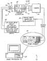
- FIG. 1schematically illustrates an LED-based illumination system according to one aspect of the invention.
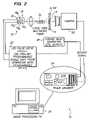
- FIG. 2schematically illustrates an LED-based illumination system according to another aspect of the invention.
- FIG. 3illustrates an embodiment in which the four colored LEDs are each driven by a separate driving circuit.
- FIG. 4illustrates an LED-based light source having a red LED, a green LED, a blue LED that is surrounded by a plurality of yellow LEDs.
- FIG. 5illustrates another LED-based light source in which a first module contains red, green, and blue LEDs.
- a second moduleis provided that includes at least one yellow LED. The two modules are arranged with respect to a beam splitter such that the yellow light is combined with the red, green, and blue light to form white light for illuminating a sample.
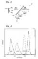
- FIG. 6illustrates a graph of light intensity as a function of wavelength for a four-color (red, green, blue, and yellow) LED-based illumination system.
- FIG. 7illustrates a graph of light intensity as a function of wavelength for a four-color (red, green, blue, and yellow) LED-based illumination system. Also shown is the absorption spectrum of the stain Eosin Y.
- FIG. 1schematically illustrates a microscope illumination system 10 .
- the microscope illumination system 10includes an illumination or light source 12 that includes at least four separate LEDs.
- the LEDsinclude at least one red LED, at least one green LED, at least one blue LED, and at least one yellow LED.
- the colors referenced aboverefer to the color of light emitted from the respective LED.
- the red LEDgenerally emits light within the range of about 625 nm to about 660 nm.
- the green LEDgenerally emits light within the range of about 480 nm to about 575 nm.
- the blue LEDgenerally emits light within the range of about 450 nm to about 500 nm.
- the yellow LEDgenerally emits light within the range of about 575 nm to about 625 nm.
- these rangesare meant to encompass the bulk of light transmitted from each respective LED and some emissions beyond the stated range are expected to occur.
- the addition of the yellow LEDfills a gap in the emission spectrum from the microscope illumination system 10 if just red, green, and blue LEDs were used as the illumination source.
- the addition of the yellow LEDallows the appearance of biological samples viewed under the LED-based microscope illumination system to more closely resemble the same samples viewed under the conventional incandescent system.
- pathologists and other trained professionalsare able to better visualize certain structures and aspects of the biological sample. For example, when certain stains such as Eosin Y and orange G stain are used, cells and cellular structures illuminated with only RGB (red, blue, green) light from LEDs appear visually different to a user compared to the same objects illuminated with a conventional broadband, incandescent light source. The addition of the yellow LED diminishes this problem.
- an microscope illumination system 10is to provide a “white” light source for imaging a biological (e.g., cytological) specimen 13 on a microscope slide 14 using a plurality of different color LEDs 16 .
- the illumination sourceincludes at least one red LED 16 R , at least one green LED 16 G , at least one blue LED 16 B , and at least one yellow LED 16 Y .
- Each LED 16may be a high brightness LED such that a bright, white light is able to illuminate the biological specimen 13 for visualization.
- the plurality of LEDsmay be formed from a combination of single discrete LEDs, or custom multi-die LED-based module.
- the individual LEDsmay be assembled to form an illumination sub-assembly from off-the-shelf components.
- an LED-based module in which individual LED dies are mounted on a common substrate 18(as shown in FIGS. 1 and 2 ) may be used.
- the LEDs 16generate heat, and as the temperature of an LED increases, the output wavelengths shift. The amount of heat generated depends on the current at which the LED is driven and the duration of time for which the current is applied.
- the LEDs 16may be driven with a pulse circuit 20 that, in certain embodiments, is synchronized with a camera 22 of the imaging system 10 to deliver short, intense pulses of light to the camera 22 during the camera integration period.
- the camera 22magnifies and captures images of the biological specimen 13 for subsequent viewing and/or analysis.
- the LEDs 16do not have to be synchronized with the camera 22 if, for example, the microscope illumination system 10 was used by a human operator.
- the camera 22may be replaced with conventional magnification optics (e.g., objective lenses and the like). In this application, the LEDs 16 would be powered continually—there is no need for synchronization.
- the LED pulseis synchronized with the camera frame integration by providing a external trigger that triggers both the camera/frame grabber 24 and the LED pulse driver 20 , for example, using a square wave generator 26 .
- the camera 22does not respond instantaneously to the trigger.
- the pulse drive circuit 20has a programmable delay that is used to synchronize the systems.
- other synchronization methodsare possible, depending on the camera type and actual implementation.
- the illumination system 10may include a processor 29 such as a personal computer that can be utilized to control the acquisition and storage of images taken via the camera 22 .
- the processor 29may coordinate various functions of the imaging sequence and also retain or transmit digital images of the biological specimens 12 .
- LEDs 16inherently produce spatially non-uniform light output and some optical applications require reasonably uniform illumination of the sample. For situations where uniformity is an issue, two types of systems for generating spatially uniform illumination may be used with LEDs 16 , namely, Koehler and fiber optic systems.
- the LEDs 16 used in either of these systemsmay be discrete LEDs 16 packaged in close proximity or multiple LED 16 dies may be integrated on a single substrate 18 to produce a more dense arrangement.
- Koehler illuminationis a standard technique for producing uniform illumination of a microscope slide 14 from the spatially non-uniform filament of an incandescent lamp used in traditional microscope illuminators. As determined by testing, this technique is equally effective at achieving uniformity when employed with LEDs 16 .
- individual LEDs 16are packaged closely together and placed in the general position of the lamp filament in the traditional Koehler illuminator 28 .
- multiple LEDs 16are coupled into a large core (around 500 to 600 ⁇ m) optical fiber 30 with lenses or other optical apparatus.
- U.S. Pat. No. 6,665,060which is incorporated by reference as if set forth fully herein discloses lenses that may be used with the LEDs 16 .
- the length of the fiber 30is selected so that the spatial non-uniformities of the LEDs 16 are mixed together and a relatively uniform spatial output from the fiber 30 is achieved.
- the output of the fiber 30is approximately Gaussian in spatial profile.
- the fiber 30may have to be displaced from the microscope slide 14 , such that only the central, relatively flat, portion of the output is used.
- multiple LED diesmay be placed on a single substrate 18 .
- Individual lensescan be placed above each die so that the radiation from each die is collected into a narrow cone.
- the Koehler illuminator 28 , 30may be omitted entirely.
- the yellow LED 16 Y in FIGS. 1 and 2fills a gap in the emission spectrum of emitted light using RGB LEDs 16 R , 16 G , 16 B .
- the intensity of illumination in the yellow region of the spectrum(about 565 nm to about 590 nm) is filled by the presence of the at least one yellow LED 16 Y .
- FIGS. 1 and 2illustrate a single yellow LED 16 Y
- multiple yellow LEDs 16 Ymay be used.
- a plurality of yellow LEDs 16 Yencircle or surround an interior portion that contains RGB LEDs 16 R , 16 G , 16 B or LED dies (see e.g., FIG. 4 ).
- the plurality of LEDs 16 R , 16 G , 16 B , and 16 Yare driven by separate driver circuits. That is to say, the at least one red LED 16 R is driven by a first driving circuit 40 R , the at least one green LED 16 G is driven by a second, separate driving circuit 40 G , the at least one blue LED 16 B is driven by a third, separate driving circuit 40 B , and the at least one yellow LED 16 Y is driven by a fourth, separate driving circuit 40 Y .
- FIG. 3illustrates this embodiment wherein a separate driving circuit 40 R , 40 G , 40 B , 40 Y is associated with each respective LED 16 R , 16 G , 16 B , and 16 Y .
- the driving circuit 40 R , 40 G , 40 B , 40 Ytypically includes a current source for applying electrical current to the LEDs 16 R , 16 G , 16 B , and 16 Y . Light is emitted from the diode when the current is forward-biased across the LED p-n junction.
- the driving circuits 40 R , 40 G , 40 B , 40 Yare capable of adjusting the brightness of each LED 16 R , 16 G , 16 B , and 16 Y independently of one another. For example, the brightness of the yellow LED 16 Y may be adjusted independent of the red, green, and blue LEDs 16 R , 16 G , 16 B . Brightness levels are adjusted using pulse width modulation.
- Pulse width modulationis a known method for controlling LED brightness levels.
- the driving circuits 40 R , 40 G , 40 B , 40 Ymay be implemented using one or more microprocessors.
- FIGS. 4 and 5illustrate two exemplary configurations for an LED-based light source 50 for the illumination system 10 .
- a series of yellow LEDs 16 Ysurround a LED module 42 having red, green, and blue LEDs 16 R , 16 G , 16 B .
- the yellow LEDs 16 Yare arranged in a symmetrical manner about the LED module 42 .
- FIG. 5illustrates another configuration of an LED-based light source 50 in which a module 42 containing red, green, and blue LEDs 16 R , 16 G , 16 B emits radiation into a beam splitter BS.
- a separate module 42 containing a yellow LED 16 Yis positioned generally perpendicular to the optical path of the RGB module 42 such that the yellow light emitted from the yellow LED 16 Y is combined or merged with the red, green, and blue light transmitted through the beam splitter.
- the LED-base light sources 50 of FIGS. 4 and 5are illustrative and other configurations combining red, green, blue, and yellow LEDs 16 R , 16 G , 16 B , and 16 Y are contemplated to fall within the scope of the invention.
- FIG, 6illustrates the spectrum of an illumination system 10 that uses red, green, blue, and yellow LEDs 16 R , 16 G , 16 B , and 16 Y .
- This fourth (i.e., yellow) colormakes stained biological samples (e.g., cells) appear to be much closer to the colors perceived if the samples were illuminated with a broadband, incandescent light source.
- the inventionis of particular interest for stained biological samples that use biological stains such as Eosin Y (C 20 H 6 Br 4 Na 2 O 5 ; CAS No.
- FIG. 7illustrates the absorption spectrum for Eosin Y superimposed on the illumination spectra for the four color LEDs 16 R , 16 G , 16 B , and 16 Y ( FIG. 6 ). Note that for a sample stained with Eosin Y, most of the green light is blocked while the blue, yellow and red wavelengths are transmitted.
- LED-illuminated biological structurese.g., cells and cellular organelles
- incandescent light sourcestypically used in microscopes. If only RGB LEDs were used to illuminate cells, it is possible that a sample may be misdiagnosed by a pathologist or cytotechnologist because of the different appearances.
- the improved white illuminationcan be achieved by building an LED module 42 that incorporates one or more yellow LEDs 16 Y in addition to one or more of the conventional red, green and blue LEDs 16 R , 16 G , 16 B .
- multiple LED modules 42may be combined to imitate a broadband, incandescent light source. While the invention described herein has been described using a four colors of LEDs (red, green, blue, and yellow), similar results could be achieved by any combination of colors of LEDs that covers enough of the visible spectrum. For example, a combination of violet, cyan, yellow-green, and orange LEDs would provide a spectrum just as full as that created by red, green, blue, and yellow LEDs. Inclusion of additional colors of LEDs in an illumination system 10 of the type described herein may be able to provide a more complete, fuller spectrum that emulates the spectrum emitted from incandescent radiation.
Landscapes
- Physics & Mathematics (AREA)
- Chemical & Material Sciences (AREA)
- Analytical Chemistry (AREA)
- General Physics & Mathematics (AREA)
- Optics & Photonics (AREA)
- Microscoopes, Condenser (AREA)
- Investigating Or Analysing Materials By Optical Means (AREA)
- Non-Portable Lighting Devices Or Systems Thereof (AREA)
Abstract
Description
Claims (16)
Priority Applications (9)
| Application Number | Priority Date | Filing Date | Title |
|---|---|---|---|
| US11/611,123US7561329B2 (en) | 2006-12-14 | 2006-12-14 | Illumination source for stained biological samples |
| AU2007333352AAU2007333352B2 (en) | 2006-12-14 | 2007-11-30 | Illumination source comprising light emitting diodes for stained biological samples |
| JP2009541472AJP5189599B2 (en) | 2006-12-14 | 2007-11-30 | Irradiation source comprising light-emitting diodes for stained biological samples |
| EP07854894.8AEP2092385B1 (en) | 2006-12-14 | 2007-11-30 | Microscope illumination source comprising light emitting diodes for stained biological samples |
| CA2669902ACA2669902C (en) | 2006-12-14 | 2007-11-30 | Illumination source comprising light emitting diodes for stained biological samples |
| ES07854894TES2434952T3 (en) | 2006-12-14 | 2007-11-30 | Lighting source for microscope comprising light emitting diodes for stained biological samples |
| HK09110183.7AHK1131665B (en) | 2006-12-14 | 2007-11-30 | Microscope illumination source comprising light emitting diodes for stained biological samples |
| CN2007800460925ACN101558346B (en) | 2006-12-14 | 2007-11-30 | Illumination source comprising light emitting diodes for staining biological samples |
| PCT/US2007/086162WO2008073728A1 (en) | 2006-12-14 | 2007-11-30 | Illumination source comprising light emitting diodes for stained biological samples |
Applications Claiming Priority (1)
| Application Number | Priority Date | Filing Date | Title |
|---|---|---|---|
| US11/611,123US7561329B2 (en) | 2006-12-14 | 2006-12-14 | Illumination source for stained biological samples |
Publications (2)
| Publication Number | Publication Date |
|---|---|
| US20080144169A1 US20080144169A1 (en) | 2008-06-19 |
| US7561329B2true US7561329B2 (en) | 2009-07-14 |
Family
ID=39111667
Family Applications (1)
| Application Number | Title | Priority Date | Filing Date |
|---|---|---|---|
| US11/611,123Active2026-12-29US7561329B2 (en) | 2006-12-14 | 2006-12-14 | Illumination source for stained biological samples |
Country Status (8)
| Country | Link |
|---|---|
| US (1) | US7561329B2 (en) |
| EP (1) | EP2092385B1 (en) |
| JP (1) | JP5189599B2 (en) |
| CN (1) | CN101558346B (en) |
| AU (1) | AU2007333352B2 (en) |
| CA (1) | CA2669902C (en) |
| ES (1) | ES2434952T3 (en) |
| WO (1) | WO2008073728A1 (en) |
Cited By (13)
| Publication number | Priority date | Publication date | Assignee | Title |
|---|---|---|---|---|
| US20090121154A1 (en)* | 2005-11-14 | 2009-05-14 | Peter Westphal | Multispectral illuminaton Device |
| US20090146077A1 (en)* | 2007-12-11 | 2009-06-11 | Commissariat A L'energie Atomique | System of fluorescence analysis of a field in an illuminated area |
| US20090269799A1 (en)* | 2008-04-25 | 2009-10-29 | Constitutional Medical Investors, Inc. | Method of determining a complete blood count and a white blood cell differential count |
| US20110070606A1 (en)* | 2008-04-25 | 2011-03-24 | Constitution Medical, Inc. | Systems and methods for analyzing body fluids |
| US8339586B2 (en) | 2011-04-15 | 2012-12-25 | Constitution Medical, Inc. | Measuring volume and constituents of cells |
| US8348430B2 (en) | 2009-12-17 | 2013-01-08 | Alcon Research, Ltd. | Photonic lattice LEDs for ophthalmic illumination |
| US8573801B2 (en) | 2010-08-30 | 2013-11-05 | Alcon Research, Ltd. | LED illuminator |
| US9111343B2 (en) | 2011-01-18 | 2015-08-18 | Roche Diagnostics Hematology, Inc. | Microscope slide coordinate system registration |
| US20150378142A1 (en)* | 2014-06-26 | 2015-12-31 | Carl Zeiss Meditec Ag | Illumination device for an optical viewing apparatus |
| US9314374B2 (en) | 2010-03-19 | 2016-04-19 | Alcon Research, Ltd. | Stroboscopic ophthalmic illuminator |
| US9510754B2 (en) | 2014-06-26 | 2016-12-06 | Carl Zeiss Meditec Ag | Illumination arrangement and surgical microscope incorporating the same |
| US20190219808A1 (en)* | 2016-09-29 | 2019-07-18 | Olympus Corporation | Observation device |
| US11172560B2 (en) | 2016-08-25 | 2021-11-09 | Alcon Inc. | Ophthalmic illumination system with controlled chromaticity |
Families Citing this family (14)
| Publication number | Priority date | Publication date | Assignee | Title |
|---|---|---|---|---|
| KR101738013B1 (en) | 2008-06-10 | 2017-05-19 | 엑스트랄리스 테크놀로지 리미티드 | Particle detection |
| EP2211089A1 (en)* | 2009-01-26 | 2010-07-28 | GLP German Light Products GmbH | Apparatus and method for outputting a mixed-colored light beam |
| JP5771156B2 (en)* | 2009-03-12 | 2015-08-26 | ジーイー・ヘルスケア・バイオサイエンス・コーポレイション | Fiber optic light source |
| CN102460527B (en) | 2009-05-01 | 2015-06-03 | 爱克斯崔里斯科技有限公司 | Improvements to Particle Detectors |
| US20110148304A1 (en)* | 2009-12-22 | 2011-06-23 | Artsyukhovich Alexander N | Thermoelectric cooling for increased brightness in a white light l.e.d. illuminator |
| WO2012030505A1 (en)* | 2010-08-30 | 2012-03-08 | Alcon Research, Ltd. | Led illuminator |
| RU2462195C2 (en)* | 2010-12-31 | 2012-09-27 | Российская Федерация, От Имени Которой Выступает Министерство Промышленности И Торговли Российской Федерации | Method of examination and diagnostics of condition of biological object or its part |
| JP5892594B2 (en)* | 2012-01-24 | 2016-03-23 | 学校法人東京電機大学 | Cultured cell observation system with multi-point illumination |
| CN105102945B (en)* | 2013-01-10 | 2018-07-10 | 加利珀生命科学股份有限公司 | Multi-optical spectrum imaging system and method |
| US10580128B2 (en)* | 2013-01-10 | 2020-03-03 | Akoya Biosciences, Inc. | Whole slide multispectral imaging systems and methods |
| DE102013006996A1 (en) | 2013-04-19 | 2014-10-23 | Carl Zeiss Microscopy Gmbh | Method for illuminating an object in a digital light microscope, digital light microscope and bright field incident illumination device for a digital light microscope |
| CN104792499B (en)* | 2015-04-13 | 2017-06-06 | 浙江大学 | A kind of biological tissue's lighting quality detection method based on human eye vision |
| US11067526B2 (en) | 2017-08-17 | 2021-07-20 | Abbott Point Of Care Inc. | Devices, systems, and methods for performing optical and electrochemical assays |
| JP7088527B2 (en)* | 2017-12-14 | 2022-06-21 | 株式会社レクザム | Lens meter |
Citations (21)
| Publication number | Priority date | Publication date | Assignee | Title |
|---|---|---|---|---|
| DE3418839A1 (en)* | 1984-05-21 | 1985-11-21 | Hoelzle & Chelius GmbH, 6078 Neu Isenburg | Device for colorimetry/photometry |
| DE3734691A1 (en) | 1986-10-16 | 1988-04-28 | Olympus Optical Co | Illuminating device for microscopes |
| US5291195A (en)* | 1990-02-20 | 1994-03-01 | H. Koch & Sons Co. | Target light for docking |
| US5936764A (en)* | 1993-04-15 | 1999-08-10 | Kowa Company Ltd. | Laser scanning optical microscope |
| GB2348968A (en) | 1999-04-12 | 2000-10-18 | Ctp Coil Limited | LED illuminated manifier |
| US6150774A (en) | 1997-08-26 | 2000-11-21 | Color Kinetics, Incorporated | Multicolored LED lighting method and apparatus |
| US6193401B1 (en) | 1997-02-15 | 2001-02-27 | University Of Strathclyde | Optical element |
| DE19962779A1 (en) | 1999-12-23 | 2001-06-28 | Byk Gardner Gmbh | Device for quantitative determination of surface quality; has illumination unit with red, green and blue light and has detection unit with filter and photosensor to detect light reflected from surface |
| US6305818B1 (en)* | 1998-03-19 | 2001-10-23 | Ppt Vision, Inc. | Method and apparatus for L.E.D. illumination |
| EP1150154A1 (en) | 2000-04-26 | 2001-10-31 | Cobra electronic GmbH | Device and method for annular illumination, especially for bright field illumination of microscopes |
| US20030042493A1 (en) | 2001-08-31 | 2003-03-06 | Yuri Kazakevich | Solid-state light source |
| US6659578B2 (en)* | 2001-10-02 | 2003-12-09 | Hewlett-Packard Development Company, L.P. | Tuning system for a compact optical sensor |
| US6665060B1 (en) | 1999-10-29 | 2003-12-16 | Cytyc Corporation | Cytological imaging system and method |
| US6683419B2 (en) | 2002-06-24 | 2004-01-27 | Dialight Corporation | Electrical control for an LED light source, including dimming control |
| US20040190132A1 (en) | 2003-03-19 | 2004-09-30 | Axel Laschke | Control unit for mixed light illumination, especially for microscopy |
| US6806659B1 (en) | 1997-08-26 | 2004-10-19 | Color Kinetics, Incorporated | Multicolored LED lighting method and apparatus |
| US20040263960A1 (en) | 2003-06-27 | 2004-12-30 | Olympus Corporation | Stereo microscope |
| EP1510847A1 (en) | 2003-08-28 | 2005-03-02 | Leica Microsystems (Schweiz) AG | Stereo surgical microscope having an integrated incident illumination device |
| US20050047172A1 (en)* | 2003-08-28 | 2005-03-03 | Ulrich Sander | Light-emitting diode illumination system for an optical observation device, in particular a stereomicroscope or stereo surgical microscope |
| US20070139638A1 (en)* | 2005-12-20 | 2007-06-21 | Cytyc Corporation | Microscope with LED illumination source |
| US7308296B2 (en) | 1997-08-26 | 2007-12-11 | Color Kinetics Incorporated | Precision illumination methods and systems |
Family Cites Families (5)
| Publication number | Priority date | Publication date | Assignee | Title |
|---|---|---|---|---|
| JP3228098B2 (en)* | 1995-11-01 | 2001-11-12 | 横河電機株式会社 | Light source |
| EP1111333A4 (en)* | 1999-06-29 | 2002-08-28 | Omron Tateisi Electronics Co | Light source device, spectroscope comprising the light source device, and film thickness sensor |
| JP2003337286A (en)* | 2002-05-21 | 2003-11-28 | Mejiro Precision:Kk | Illumination device and illumination method |
| TWI302756B (en) | 2004-04-19 | 2008-11-01 | Phoseon Technology Inc | Imaging semiconductor structures using solid state illumination |
| JP2006209698A (en)* | 2005-01-31 | 2006-08-10 | Olympus Corp | Target tracking device, microscope system and target tracking program |
- 2006
- 2006-12-14USUS11/611,123patent/US7561329B2/enactiveActive
- 2007
- 2007-11-30AUAU2007333352Apatent/AU2007333352B2/enactiveActive
- 2007-11-30EPEP07854894.8Apatent/EP2092385B1/enactiveActive
- 2007-11-30CACA2669902Apatent/CA2669902C/enactiveActive
- 2007-11-30ESES07854894Tpatent/ES2434952T3/enactiveActive
- 2007-11-30JPJP2009541472Apatent/JP5189599B2/enactiveActive
- 2007-11-30WOPCT/US2007/086162patent/WO2008073728A1/enactiveApplication Filing
- 2007-11-30CNCN2007800460925Apatent/CN101558346B/enactiveActive
Patent Citations (23)
| Publication number | Priority date | Publication date | Assignee | Title |
|---|---|---|---|---|
| DE3418839A1 (en)* | 1984-05-21 | 1985-11-21 | Hoelzle & Chelius GmbH, 6078 Neu Isenburg | Device for colorimetry/photometry |
| DE3734691A1 (en) | 1986-10-16 | 1988-04-28 | Olympus Optical Co | Illuminating device for microscopes |
| US4852985A (en)* | 1986-10-16 | 1989-08-01 | Olympus Optical Co., Ltd. | Illuminating device for microscopes |
| US5291195A (en)* | 1990-02-20 | 1994-03-01 | H. Koch & Sons Co. | Target light for docking |
| US5936764A (en)* | 1993-04-15 | 1999-08-10 | Kowa Company Ltd. | Laser scanning optical microscope |
| US6193401B1 (en) | 1997-02-15 | 2001-02-27 | University Of Strathclyde | Optical element |
| US6150774A (en) | 1997-08-26 | 2000-11-21 | Color Kinetics, Incorporated | Multicolored LED lighting method and apparatus |
| US7308296B2 (en) | 1997-08-26 | 2007-12-11 | Color Kinetics Incorporated | Precision illumination methods and systems |
| US6806659B1 (en) | 1997-08-26 | 2004-10-19 | Color Kinetics, Incorporated | Multicolored LED lighting method and apparatus |
| US6305818B1 (en)* | 1998-03-19 | 2001-10-23 | Ppt Vision, Inc. | Method and apparatus for L.E.D. illumination |
| GB2348968A (en) | 1999-04-12 | 2000-10-18 | Ctp Coil Limited | LED illuminated manifier |
| US6665060B1 (en) | 1999-10-29 | 2003-12-16 | Cytyc Corporation | Cytological imaging system and method |
| DE19962779A1 (en) | 1999-12-23 | 2001-06-28 | Byk Gardner Gmbh | Device for quantitative determination of surface quality; has illumination unit with red, green and blue light and has detection unit with filter and photosensor to detect light reflected from surface |
| EP1150154A1 (en) | 2000-04-26 | 2001-10-31 | Cobra electronic GmbH | Device and method for annular illumination, especially for bright field illumination of microscopes |
| WO2003021329A2 (en) | 2001-08-31 | 2003-03-13 | Smith & Nephew, Inc. | Solid-state light source |
| US20030042493A1 (en) | 2001-08-31 | 2003-03-06 | Yuri Kazakevich | Solid-state light source |
| US6659578B2 (en)* | 2001-10-02 | 2003-12-09 | Hewlett-Packard Development Company, L.P. | Tuning system for a compact optical sensor |
| US6683419B2 (en) | 2002-06-24 | 2004-01-27 | Dialight Corporation | Electrical control for an LED light source, including dimming control |
| US20040190132A1 (en) | 2003-03-19 | 2004-09-30 | Axel Laschke | Control unit for mixed light illumination, especially for microscopy |
| US20040263960A1 (en) | 2003-06-27 | 2004-12-30 | Olympus Corporation | Stereo microscope |
| EP1510847A1 (en) | 2003-08-28 | 2005-03-02 | Leica Microsystems (Schweiz) AG | Stereo surgical microscope having an integrated incident illumination device |
| US20050047172A1 (en)* | 2003-08-28 | 2005-03-03 | Ulrich Sander | Light-emitting diode illumination system for an optical observation device, in particular a stereomicroscope or stereo surgical microscope |
| US20070139638A1 (en)* | 2005-12-20 | 2007-06-21 | Cytyc Corporation | Microscope with LED illumination source |
Non-Patent Citations (7)
| Title |
|---|
| John Walsh, "The Microscope Lamp-Design Considerations for the Ideal Köhler Illuminator," Aug. 2003, 1 page, Micscape, Aug. 2003 URL: http://www.microscopy-uk-org.uk/mag/artaug03/jwled.html, downloaded on Apr. 29, 2008 (7 pages). |
| PCT International Search Report for PCT/US2006/061972, Applicant CYTYC Corp., Forms PCT/ISA/210 and 220 dated Dec. 6, 2007 (6 pages). |
| PCT International Search Report for PCT/US2007/086162, Applicant CYTYC Corp., Forms PCT/ISA/210 and 220 dated Mar. 12, 2008 (7 pages). |
| PCT Written Opinion of the International Search Authority for PCT/US2007/086162, Applicant CYTYC Corp., Form PCT/ISA/237, dated Mar. 12, 2008 (7 pages). |
| Prosecution History for U.S. Appl. No. 11/313,365: Non-Final Office Action dated Jan. 10, 2008 for U.S. Appl. No. 11/313,365 (7 pages) Amendment and Response dated Mar. 31, 2008 for U.S. Appl. No. 11/313,365 (15 pages) Notice of Allowance dated May 30, 2008 for U.S. Appl. No. 11/313,365 (7 pages). |
| Tsunemasa Taguchi, "Light Gets Solid," Spie's oe magazine, Oct. 2003, (3 pages). |
| Written Opinion for PCT/US2006/061972, Applicant CYTYC Corp., Forms PCT/ISA/237 dated Dec. 6, 2007 (7 pages). |
Cited By (36)
| Publication number | Priority date | Publication date | Assignee | Title |
|---|---|---|---|---|
| US8097865B2 (en)* | 2005-11-14 | 2012-01-17 | Carl Zeiss Microimaging Gmbh | Multispectral illuminaton device |
| US8610088B2 (en) | 2005-11-14 | 2013-12-17 | Carl Zeiss Microscopy Gmbh | Multispectral illumination device |
| US9239293B2 (en) | 2005-11-14 | 2016-01-19 | Carl Zeiss Microscopy Gmbh | Multispectral illumination device |
| US20090121154A1 (en)* | 2005-11-14 | 2009-05-14 | Peter Westphal | Multispectral illuminaton Device |
| US20090146077A1 (en)* | 2007-12-11 | 2009-06-11 | Commissariat A L'energie Atomique | System of fluorescence analysis of a field in an illuminated area |
| US8598540B2 (en)* | 2007-12-11 | 2013-12-03 | Commissariat A L'energie Atomique | System of fluorescence analysis of a field in an illuminated area |
| US10094764B2 (en) | 2008-04-25 | 2018-10-09 | Roche Diagnostics Hematology, Inc. | Systems and methods for determining a complete blood count and a white blood cell differential count |
| US10764538B2 (en) | 2008-04-25 | 2020-09-01 | Roche Diagnostics Hematology, Inc. | Systems and methods for analyzing body fluids |
| US9017610B2 (en) | 2008-04-25 | 2015-04-28 | Roche Diagnostics Hematology, Inc. | Method of determining a complete blood count and a white blood cell differential count |
| US20110070606A1 (en)* | 2008-04-25 | 2011-03-24 | Constitution Medical, Inc. | Systems and methods for analyzing body fluids |
| US9602777B2 (en) | 2008-04-25 | 2017-03-21 | Roche Diagnostics Hematology, Inc. | Systems and methods for analyzing body fluids |
| US20110014645A1 (en)* | 2008-04-25 | 2011-01-20 | Constitution Medical Investors, Inc. | Method for determining a complete blood count on a white blood cell differential count |
| US9217695B2 (en) | 2008-04-25 | 2015-12-22 | Roche Diagnostics Hematology, Inc. | Method for determining a complete blood count on a white blood cell differential count |
| US9083857B2 (en) | 2008-04-25 | 2015-07-14 | Roche Diagnostics Hematology, Inc. | Systems and methods for analyzing body fluids |
| US20100284602A1 (en)* | 2008-04-25 | 2010-11-11 | Constitution Medical Investors, Inc. | Method for determining a complete blood count on a white blood cell differential count |
| US20090269799A1 (en)* | 2008-04-25 | 2009-10-29 | Constitutional Medical Investors, Inc. | Method of determining a complete blood count and a white blood cell differential count |
| US8815537B2 (en) | 2008-04-25 | 2014-08-26 | Roche Diagnostics Hematology, Inc. | Method for determining a complete blood count on a white blood cell differential count |
| US8348430B2 (en) | 2009-12-17 | 2013-01-08 | Alcon Research, Ltd. | Photonic lattice LEDs for ophthalmic illumination |
| US8371694B2 (en) | 2009-12-17 | 2013-02-12 | Alcon Research, Ltd. | Bichromatic white ophthalmic illuminator |
| US9314374B2 (en) | 2010-03-19 | 2016-04-19 | Alcon Research, Ltd. | Stroboscopic ophthalmic illuminator |
| US8573801B2 (en) | 2010-08-30 | 2013-11-05 | Alcon Research, Ltd. | LED illuminator |
| US9280699B2 (en) | 2011-01-18 | 2016-03-08 | Roche Diagnostics Hematology, Inc. | Microscope slide coordinate system registration |
| US9111343B2 (en) | 2011-01-18 | 2015-08-18 | Roche Diagnostics Hematology, Inc. | Microscope slide coordinate system registration |
| US10068126B2 (en) | 2011-01-18 | 2018-09-04 | Roche Diagnostics Hematology, Inc. | Microscope slide coordinate system registration |
| US8488111B2 (en) | 2011-04-15 | 2013-07-16 | Constitution Medical, Inc. | Measuring volume and constituents of cells |
| US8477294B2 (en) | 2011-04-15 | 2013-07-02 | Constitution Medical, Inc. | Measuring volume and constituents of cells |
| US8339586B2 (en) | 2011-04-15 | 2012-12-25 | Constitution Medical, Inc. | Measuring volume and constituents of cells |
| US10281382B2 (en) | 2011-04-15 | 2019-05-07 | Roche Diagnostics Hematology, Inc. | Measuring volume and constituents of cells |
| US9588033B2 (en) | 2011-04-15 | 2017-03-07 | Roche Diagnostics Hematology, Inc. | Measuring volume and constituents of cells |
| US8922761B2 (en) | 2011-04-15 | 2014-12-30 | Roche Diagnostics Hematology, Inc. | Measuring volume and constituents of cells |
| US8345227B2 (en) | 2011-04-15 | 2013-01-01 | Constitution Medical, Inc. | Measuring volume and constituents of cells |
| US20150378142A1 (en)* | 2014-06-26 | 2015-12-31 | Carl Zeiss Meditec Ag | Illumination device for an optical viewing apparatus |
| US9568722B2 (en)* | 2014-06-26 | 2017-02-14 | Carl Zeiss Meditec Ag | Illumination device for an optical viewing apparatus |
| US9510754B2 (en) | 2014-06-26 | 2016-12-06 | Carl Zeiss Meditec Ag | Illumination arrangement and surgical microscope incorporating the same |
| US11172560B2 (en) | 2016-08-25 | 2021-11-09 | Alcon Inc. | Ophthalmic illumination system with controlled chromaticity |
| US20190219808A1 (en)* | 2016-09-29 | 2019-07-18 | Olympus Corporation | Observation device |
Also Published As
| Publication number | Publication date |
|---|---|
| HK1131665A1 (en) | 2010-01-29 |
| JP2010514101A (en) | 2010-04-30 |
| CA2669902C (en) | 2015-03-17 |
| EP2092385B1 (en) | 2013-08-14 |
| CN101558346A (en) | 2009-10-14 |
| CA2669902A1 (en) | 2008-06-19 |
| AU2007333352A1 (en) | 2008-06-19 |
| US20080144169A1 (en) | 2008-06-19 |
| JP5189599B2 (en) | 2013-04-24 |
| ES2434952T3 (en) | 2013-12-18 |
| EP2092385A1 (en) | 2009-08-26 |
| AU2007333352B2 (en) | 2013-02-21 |
| WO2008073728A1 (en) | 2008-06-19 |
| CN101558346B (en) | 2012-01-25 |
Similar Documents
| Publication | Publication Date | Title |
|---|---|---|
| US7561329B2 (en) | Illumination source for stained biological samples | |
| US7229202B2 (en) | Light-emitting diode illumination system for an optical observation device, in particular a stereomicroscope or stereo surgical microscope | |
| US10145738B2 (en) | Optical filter system and fluorescence detection system | |
| CN102902053B (en) | microscope illumination method and microscope | |
| US20050152028A1 (en) | Illumination device for a microscope | |
| US20070211460A1 (en) | Multi-color LED light source for microscope illumination | |
| EP1602960B1 (en) | Microscope | |
| US20110234782A1 (en) | Apparatus to provide white illuminating light | |
| CN102902052A (en) | Microscope lighting process and microscope | |
| CN109212736B (en) | Illumination system, microscope comprising an illumination system and microscopy method | |
| CN112043240A (en) | Light source, system for fluorescence diagnosis and method for fluorescence diagnosis | |
| CN107883204A (en) | Light source module and the analytical instrument for analyzing sample | |
| KR20230004630A (en) | Optical module having three or more colors of fluorescent light sources and method of using the same | |
| US3947099A (en) | Solid state color anomaloscope | |
| US11079330B2 (en) | Filter set, system, and method for observing protoporphyrin IX | |
| US20040152987A1 (en) | Inspection system and inspection method | |
| CN109414160A (en) | The method of observation device and controlled observation equipment | |
| JP2018041856A (en) | LED for visible illumination | |
| US20050259437A1 (en) | Apparatus, systems and methods relating to illumination for microscopes | |
| CN107044886A (en) | A kind of multiband spectrum imaging source, imaging method and microscope | |
| HK1131665B (en) | Microscope illumination source comprising light emitting diodes for stained biological samples | |
| RU51734U1 (en) | ILLUMINATOR | |
| Hohman | LED Light Source: Major Advance in Fluorescence Microscopy | |
| Whoriskey | LEDs in Microscopy: An Emerging Research Tool | |
| RU52318U1 (en) | LIGHT SOURCE FOR SURGICAL LUMINAIRES |
Legal Events
| Date | Code | Title | Description |
|---|---|---|---|
| AS | Assignment | Owner name:CYTYC CORPORATION, MASSACHUSETTS Free format text:ASSIGNMENT OF ASSIGNORS INTEREST;ASSIGNORS:ZAHNISER, MICHAEL;ZAHNISER, DAVID;PARSONS, DANIEL;REEL/FRAME:018637/0067;SIGNING DATES FROM 20061211 TO 20061214 | |
| AS | Assignment | Owner name:GOLDMAN SACHS CREDIT PARTNERS L.P.,CALIFORNIA Free format text:PATENT SECURITY AGREEMENT;ASSIGNOR:CYTYC CORPORATION;REEL/FRAME:020018/0529 Effective date:20071022 Owner name:GOLDMAN SACHS CREDIT PARTNERS L.P., CALIFORNIA Free format text:PATENT SECURITY AGREEMENT;ASSIGNOR:CYTYC CORPORATION;REEL/FRAME:020018/0529 Effective date:20071022 | |
| AS | Assignment | Owner name:GOLDMAN SACHS CREDIT PARTNERS L.P., AS COLLATERAL Free format text:PATENT SECURITY AGREEMENT;ASSIGNOR:CYTYC CORPORATION;REEL/FRAME:021301/0879 Effective date:20080717 | |
| FEPP | Fee payment procedure | Free format text:PAYOR NUMBER ASSIGNED (ORIGINAL EVENT CODE: ASPN); ENTITY STATUS OF PATENT OWNER: LARGE ENTITY | |
| STCF | Information on status: patent grant | Free format text:PATENTED CASE | |
| AS | Assignment | Owner name:HOLOGIC, INC., MASSACHUSETTS Free format text:TERMINATION OF PATENT SECURITY AGREEMENTS AND RELEASE OF SECURITY INTERESTS;ASSIGNOR:GOLDMAN SACHS CREDIT PARTNERS, L.P., AS COLLATERAL AGENT;REEL/FRAME:024892/0001 Effective date:20100819 Owner name:CYTYC CORPORATION, MASSACHUSETTS Free format text:TERMINATION OF PATENT SECURITY AGREEMENTS AND RELEASE OF SECURITY INTERESTS;ASSIGNOR:GOLDMAN SACHS CREDIT PARTNERS, L.P., AS COLLATERAL AGENT;REEL/FRAME:024892/0001 Effective date:20100819 Owner name:CYTYC SURGICAL PRODUCTS II LIMITED PARTNERSHIP, MA Free format text:TERMINATION OF PATENT SECURITY AGREEMENTS AND RELEASE OF SECURITY INTERESTS;ASSIGNOR:GOLDMAN SACHS CREDIT PARTNERS, L.P., AS COLLATERAL AGENT;REEL/FRAME:024892/0001 Effective date:20100819 Owner name:DIRECT RADIOGRAPHY CORP., DELAWARE Free format text:TERMINATION OF PATENT SECURITY AGREEMENTS AND RELEASE OF SECURITY INTERESTS;ASSIGNOR:GOLDMAN SACHS CREDIT PARTNERS, L.P., AS COLLATERAL AGENT;REEL/FRAME:024892/0001 Effective date:20100819 Owner name:CYTYC SURGICAL PRODUCTS III, INC., MASSACHUSETTS Free format text:TERMINATION OF PATENT SECURITY AGREEMENTS AND RELEASE OF SECURITY INTERESTS;ASSIGNOR:GOLDMAN SACHS CREDIT PARTNERS, L.P., AS COLLATERAL AGENT;REEL/FRAME:024892/0001 Effective date:20100819 Owner name:CYTYC PRENATAL PRODUCTS CORP., MASSACHUSETTS Free format text:TERMINATION OF PATENT SECURITY AGREEMENTS AND RELEASE OF SECURITY INTERESTS;ASSIGNOR:GOLDMAN SACHS CREDIT PARTNERS, L.P., AS COLLATERAL AGENT;REEL/FRAME:024892/0001 Effective date:20100819 Owner name:THIRD WAVE TECHNOLOGIES, INC., WISCONSIN Free format text:TERMINATION OF PATENT SECURITY AGREEMENTS AND RELEASE OF SECURITY INTERESTS;ASSIGNOR:GOLDMAN SACHS CREDIT PARTNERS, L.P., AS COLLATERAL AGENT;REEL/FRAME:024892/0001 Effective date:20100819 Owner name:R2 TECHNOLOGY, INC., CALIFORNIA Free format text:TERMINATION OF PATENT SECURITY AGREEMENTS AND RELEASE OF SECURITY INTERESTS;ASSIGNOR:GOLDMAN SACHS CREDIT PARTNERS, L.P., AS COLLATERAL AGENT;REEL/FRAME:024892/0001 Effective date:20100819 Owner name:CYTYC SURGICAL PRODUCTS LIMITED PARTNERSHIP, MASSA Free format text:TERMINATION OF PATENT SECURITY AGREEMENTS AND RELEASE OF SECURITY INTERESTS;ASSIGNOR:GOLDMAN SACHS CREDIT PARTNERS, L.P., AS COLLATERAL AGENT;REEL/FRAME:024892/0001 Effective date:20100819 Owner name:BIOLUCENT, LLC, CALIFORNIA Free format text:TERMINATION OF PATENT SECURITY AGREEMENTS AND RELEASE OF SECURITY INTERESTS;ASSIGNOR:GOLDMAN SACHS CREDIT PARTNERS, L.P., AS COLLATERAL AGENT;REEL/FRAME:024892/0001 Effective date:20100819 Owner name:SUROS SURGICAL SYSTEMS, INC., INDIANA Free format text:TERMINATION OF PATENT SECURITY AGREEMENTS AND RELEASE OF SECURITY INTERESTS;ASSIGNOR:GOLDMAN SACHS CREDIT PARTNERS, L.P., AS COLLATERAL AGENT;REEL/FRAME:024892/0001 Effective date:20100819 | |
| AS | Assignment | Owner name:GOLDMAN SACHS BANK USA, NEW YORK Free format text:SECURITY AGREEMENT;ASSIGNORS:HOLOGIC, INC.;BIOLUCENT, LLC;CYTYC CORPORATION;AND OTHERS;REEL/FRAME:028810/0745 Effective date:20120801 | |
| FPAY | Fee payment | Year of fee payment:4 | |
| AS | Assignment | Owner name:CYTYC SURGICAL PRODUCTS, LIMITED PARTNERSHIP, MASSACHUSETTS Free format text:SECURITY INTEREST RELEASE REEL/FRAME 028810/0745;ASSIGNOR:GOLDMAN SACHS BANK USA, AS COLLATERAL AGENT;REEL/FRAME:035820/0239 Effective date:20150529 Owner name:GEN-PROBE INCORPORATED, MASSACHUSETTS Free format text:SECURITY INTEREST RELEASE REEL/FRAME 028810/0745;ASSIGNOR:GOLDMAN SACHS BANK USA, AS COLLATERAL AGENT;REEL/FRAME:035820/0239 Effective date:20150529 Owner name:CYTYC SURGICAL PRODUCTS, LIMITED PARTNERSHIP, MASS Free format text:SECURITY INTEREST RELEASE REEL/FRAME 028810/0745;ASSIGNOR:GOLDMAN SACHS BANK USA, AS COLLATERAL AGENT;REEL/FRAME:035820/0239 Effective date:20150529 Owner name:CYTYC CORPORATION, MASSACHUSETTS Free format text:SECURITY INTEREST RELEASE REEL/FRAME 028810/0745;ASSIGNOR:GOLDMAN SACHS BANK USA, AS COLLATERAL AGENT;REEL/FRAME:035820/0239 Effective date:20150529 Owner name:SUROS SURGICAL SYSTEMS, INC., MASSACHUSETTS Free format text:SECURITY INTEREST RELEASE REEL/FRAME 028810/0745;ASSIGNOR:GOLDMAN SACHS BANK USA, AS COLLATERAL AGENT;REEL/FRAME:035820/0239 Effective date:20150529 Owner name:BIOLUCENT, LLC, MASSACHUSETTS Free format text:SECURITY INTEREST RELEASE REEL/FRAME 028810/0745;ASSIGNOR:GOLDMAN SACHS BANK USA, AS COLLATERAL AGENT;REEL/FRAME:035820/0239 Effective date:20150529 Owner name:THIRD WAVE TECHNOLOGIES, INC., MASSACHUSETTS Free format text:SECURITY INTEREST RELEASE REEL/FRAME 028810/0745;ASSIGNOR:GOLDMAN SACHS BANK USA, AS COLLATERAL AGENT;REEL/FRAME:035820/0239 Effective date:20150529 Owner name:HOLOGIC, INC., MASSACHUSETTS Free format text:SECURITY INTEREST RELEASE REEL/FRAME 028810/0745;ASSIGNOR:GOLDMAN SACHS BANK USA, AS COLLATERAL AGENT;REEL/FRAME:035820/0239 Effective date:20150529 | |
| AS | Assignment | Owner name:BANK OF AMERICA, N.A., AS COLLATERAL AGENT, NORTH CAROLINA Free format text:SECURITY AGREEMENT;ASSIGNORS:HOLOGIC, INC.;BIOLUCENT, LLC;CYTYC CORPORATION;AND OTHERS;REEL/FRAME:036307/0199 Effective date:20150529 Owner name:BANK OF AMERICA, N.A., AS COLLATERAL AGENT, NORTH Free format text:SECURITY AGREEMENT;ASSIGNORS:HOLOGIC, INC.;BIOLUCENT, LLC;CYTYC CORPORATION;AND OTHERS;REEL/FRAME:036307/0199 Effective date:20150529 | |
| FPAY | Fee payment | Year of fee payment:8 | |
| AS | Assignment | Owner name:CYTYC SURGICAL PRODUCTS, LIMITED PARTNERSHIP, MASSACHUSETTS Free format text:CORRECTIVE ASSIGNMENT TO CORRECT THE INCORRECT PATENT NO. 8081301 PREVIOUSLY RECORDED AT REEL: 035820 FRAME: 0239. ASSIGNOR(S) HEREBY CONFIRMS THE SECURITY INTEREST RELEASE;ASSIGNOR:GOLDMAN SACHS BANK USA, AS COLLATERAL AGENT;REEL/FRAME:044727/0529 Effective date:20150529 Owner name:GOLDMAN SACHS BANK USA, NEW YORK Free format text:CORRECTIVE ASSIGNMENT TO CORRECT THE INCORRECT PATENT NO. 8081301 PREVIOUSLY RECORDED AT REEL: 028810 FRAME: 0745. ASSIGNOR(S) HEREBY CONFIRMS THE SECURITY AGREEMENT;ASSIGNORS:HOLOGIC, INC.;BIOLUCENT, LLC;CYTYC CORPORATION;AND OTHERS;REEL/FRAME:044432/0565 Effective date:20120801 Owner name:BIOLUCENT, LLC, MASSACHUSETTS Free format text:CORRECTIVE ASSIGNMENT TO CORRECT THE INCORRECT PATENT NO. 8081301 PREVIOUSLY RECORDED AT REEL: 035820 FRAME: 0239. ASSIGNOR(S) HEREBY CONFIRMS THE SECURITY INTEREST RELEASE;ASSIGNOR:GOLDMAN SACHS BANK USA, AS COLLATERAL AGENT;REEL/FRAME:044727/0529 Effective date:20150529 Owner name:HOLOGIC, INC., MASSACHUSETTS Free format text:CORRECTIVE ASSIGNMENT TO CORRECT THE INCORRECT PATENT NO. 8081301 PREVIOUSLY RECORDED AT REEL: 035820 FRAME: 0239. ASSIGNOR(S) HEREBY CONFIRMS THE SECURITY INTEREST RELEASE;ASSIGNOR:GOLDMAN SACHS BANK USA, AS COLLATERAL AGENT;REEL/FRAME:044727/0529 Effective date:20150529 Owner name:CYTYC SURGICAL PRODUCTS, LIMITED PARTNERSHIP, MASS Free format text:CORRECTIVE ASSIGNMENT TO CORRECT THE INCORRECT PATENT NO. 8081301 PREVIOUSLY RECORDED AT REEL: 035820 FRAME: 0239. ASSIGNOR(S) HEREBY CONFIRMS THE SECURITY INTEREST RELEASE;ASSIGNOR:GOLDMAN SACHS BANK USA, AS COLLATERAL AGENT;REEL/FRAME:044727/0529 Effective date:20150529 Owner name:THIRD WAVE TECHNOLOGIES, INC., MASSACHUSETTS Free format text:CORRECTIVE ASSIGNMENT TO CORRECT THE INCORRECT PATENT NO. 8081301 PREVIOUSLY RECORDED AT REEL: 035820 FRAME: 0239. ASSIGNOR(S) HEREBY CONFIRMS THE SECURITY INTEREST RELEASE;ASSIGNOR:GOLDMAN SACHS BANK USA, AS COLLATERAL AGENT;REEL/FRAME:044727/0529 Effective date:20150529 Owner name:GEN-PROBE INCORPORATED, MASSACHUSETTS Free format text:CORRECTIVE ASSIGNMENT TO CORRECT THE INCORRECT PATENT NO. 8081301 PREVIOUSLY RECORDED AT REEL: 035820 FRAME: 0239. ASSIGNOR(S) HEREBY CONFIRMS THE SECURITY INTEREST RELEASE;ASSIGNOR:GOLDMAN SACHS BANK USA, AS COLLATERAL AGENT;REEL/FRAME:044727/0529 Effective date:20150529 Owner name:SUROS SURGICAL SYSTEMS, INC., MASSACHUSETTS Free format text:CORRECTIVE ASSIGNMENT TO CORRECT THE INCORRECT PATENT NO. 8081301 PREVIOUSLY RECORDED AT REEL: 035820 FRAME: 0239. ASSIGNOR(S) HEREBY CONFIRMS THE SECURITY INTEREST RELEASE;ASSIGNOR:GOLDMAN SACHS BANK USA, AS COLLATERAL AGENT;REEL/FRAME:044727/0529 Effective date:20150529 Owner name:CYTYC CORPORATION, MASSACHUSETTS Free format text:CORRECTIVE ASSIGNMENT TO CORRECT THE INCORRECT PATENT NO. 8081301 PREVIOUSLY RECORDED AT REEL: 035820 FRAME: 0239. ASSIGNOR(S) HEREBY CONFIRMS THE SECURITY INTEREST RELEASE;ASSIGNOR:GOLDMAN SACHS BANK USA, AS COLLATERAL AGENT;REEL/FRAME:044727/0529 Effective date:20150529 | |
| MAFP | Maintenance fee payment | Free format text:PAYMENT OF MAINTENANCE FEE, 12TH YEAR, LARGE ENTITY (ORIGINAL EVENT CODE: M1553); ENTITY STATUS OF PATENT OWNER: LARGE ENTITY Year of fee payment:12 |