US7561057B2 - Method and apparatus for detecting severity of water leaks - Google Patents
Method and apparatus for detecting severity of water leaksDownload PDFInfo
- Publication number
- US7561057B2 US7561057B2US11/216,225US21622505AUS7561057B2US 7561057 B2US7561057 B2US 7561057B2US 21622505 AUS21622505 AUS 21622505AUS 7561057 B2US7561057 B2US 7561057B2
- Authority
- US
- United States
- Prior art keywords
- sensor
- unit
- water
- repeater
- moisture
- Prior art date
- Legal status (The legal status is an assumption and is not a legal conclusion. Google has not performed a legal analysis and makes no representation as to the accuracy of the status listed.)
- Expired - Fee Related, expires
Links
- XLYOFNOQVPJJNP-UHFFFAOYSA-NwaterSubstancesOXLYOFNOQVPJJNP-UHFFFAOYSA-N0.000titleclaimsabstractdescription172
- 238000000034methodMethods0.000titledescription22
- 239000000523sampleSubstances0.000claimsdescription65
- 239000000758substrateSubstances0.000claimsdescription10
- 239000003795chemical substances by applicationSubstances0.000claimsdescription8
- 239000004020conductorSubstances0.000claimsdescription2
- 238000012544monitoring processMethods0.000description78
- 239000000779smokeSubstances0.000description27
- 241000233866FungiSpecies0.000description26
- 230000006854communicationEffects0.000description21
- 238000004891communicationMethods0.000description21
- 238000012360testing methodMethods0.000description18
- 230000005540biological transmissionEffects0.000description16
- 238000012423maintenanceMethods0.000description16
- 239000007789gasSubstances0.000description14
- 230000002547anomalous effectEffects0.000description13
- 230000008569processEffects0.000description13
- 230000036541healthEffects0.000description12
- 239000000463materialSubstances0.000description12
- 238000005259measurementMethods0.000description11
- 238000001228spectrumMethods0.000description11
- 230000008859changeEffects0.000description10
- 230000002349favourable effectEffects0.000description10
- ATUOYWHBWRKTHZ-UHFFFAOYSA-NPropaneChemical compoundCCCATUOYWHBWRKTHZ-UHFFFAOYSA-N0.000description8
- 238000001514detection methodMethods0.000description8
- VNWKTOKETHGBQD-UHFFFAOYSA-NmethaneChemical compoundCVNWKTOKETHGBQD-UHFFFAOYSA-N0.000description8
- 230000000737periodic effectEffects0.000description8
- BASFCYQUMIYNBI-UHFFFAOYSA-NplatinumChemical compound[Pt]BASFCYQUMIYNBI-UHFFFAOYSA-N0.000description8
- UGFAIRIUMAVXCW-UHFFFAOYSA-NCarbon monoxideChemical compound[O+]#[C-]UGFAIRIUMAVXCW-UHFFFAOYSA-N0.000description6
- 229910002091carbon monoxideInorganic materials0.000description6
- 238000010586diagramMethods0.000description6
- -1fireSubstances0.000description6
- 238000007747platingMethods0.000description6
- 238000009428plumbingMethods0.000description6
- 239000004509smoke generatorSubstances0.000description6
- 239000012530fluidSubstances0.000description5
- 230000007175bidirectional communicationEffects0.000description4
- 238000004364calculation methodMethods0.000description4
- 230000006870functionEffects0.000description4
- PCHJSUWPFVWCPO-UHFFFAOYSA-NgoldChemical compound[Au]PCHJSUWPFVWCPO-UHFFFAOYSA-N0.000description4
- 229910052737goldInorganic materials0.000description4
- 239000010931goldSubstances0.000description4
- 239000003345natural gasSubstances0.000description4
- 229910052697platinumInorganic materials0.000description4
- 239000001294propaneSubstances0.000description4
- 230000001360synchronised effectEffects0.000description4
- 239000013043chemical agentSubstances0.000description3
- 238000009833condensationMethods0.000description3
- 230000005494condensationEffects0.000description3
- 238000010438heat treatmentMethods0.000description3
- 238000009434installationMethods0.000description3
- 230000009471actionEffects0.000description2
- 230000004913activationEffects0.000description2
- 238000001994activationMethods0.000description2
- 230000002411adverseEffects0.000description2
- 230000008901benefitEffects0.000description2
- 230000001413cellular effectEffects0.000description2
- 230000008878couplingEffects0.000description2
- 238000010168coupling processMethods0.000description2
- 238000005859coupling reactionMethods0.000description2
- 239000000446fuelSubstances0.000description2
- 238000011835investigationMethods0.000description2
- 239000002574poisonSubstances0.000description2
- 231100000614poisonToxicity0.000description2
- 229910052704radonInorganic materials0.000description2
- SYUHGPGVQRZVTB-UHFFFAOYSA-Nradon atomChemical compound[Rn]SYUHGPGVQRZVTB-UHFFFAOYSA-N0.000description2
- 239000002904solventSubstances0.000description2
- OKTJSMMVPCPJKN-UHFFFAOYSA-NCarbonChemical compound[C]OKTJSMMVPCPJKN-UHFFFAOYSA-N0.000description1
- RYGMFSIKBFXOCR-UHFFFAOYSA-NCopperChemical compound[Cu]RYGMFSIKBFXOCR-UHFFFAOYSA-N0.000description1
- LFQSCWFLJHTTHZ-UHFFFAOYSA-NEthanolChemical compoundCCOLFQSCWFLJHTTHZ-UHFFFAOYSA-N0.000description1
- 230000002159abnormal effectEffects0.000description1
- 239000002253acidSubstances0.000description1
- 150000007513acidsChemical class0.000description1
- 238000004378air conditioningMethods0.000description1
- 238000009529body temperature measurementMethods0.000description1
- 229910052799carbonInorganic materials0.000description1
- 238000010276constructionMethods0.000description1
- 229910052802copperInorganic materials0.000description1
- 239000010949copperSubstances0.000description1
- 239000003599detergentSubstances0.000description1
- 230000003203everyday effectEffects0.000description1
- 239000000284extractSubstances0.000description1
- 230000001939inductive effectEffects0.000description1
- 230000002401inhibitory effectEffects0.000description1
- 229910052500inorganic mineralInorganic materials0.000description1
- 230000002452interceptive effectEffects0.000description1
- 150000008040ionic compoundsChemical class0.000description1
- 230000007257malfunctionEffects0.000description1
- 229910052751metalInorganic materials0.000description1
- 239000002184metalSubstances0.000description1
- 239000011707mineralSubstances0.000description1
- 239000000203mixtureSubstances0.000description1
- 238000012806monitoring deviceMethods0.000description1
- 239000004033plasticSubstances0.000description1
- 238000012545processingMethods0.000description1
- 230000001105regulatory effectEffects0.000description1
- 230000008439repair processEffects0.000description1
- 230000004044responseEffects0.000description1
- 150000003839saltsChemical class0.000description1
- 238000006467substitution reactionMethods0.000description1
- 238000012546transferMethods0.000description1
Images


Classifications
- G—PHYSICS
- G01—MEASURING; TESTING
- G01M—TESTING STATIC OR DYNAMIC BALANCE OF MACHINES OR STRUCTURES; TESTING OF STRUCTURES OR APPARATUS, NOT OTHERWISE PROVIDED FOR
- G01M3/00—Investigating fluid-tightness of structures
- G01M3/02—Investigating fluid-tightness of structures by using fluid or vacuum
- G01M3/04—Investigating fluid-tightness of structures by using fluid or vacuum by detecting the presence of fluid at the leakage point
- G01M3/16—Investigating fluid-tightness of structures by using fluid or vacuum by detecting the presence of fluid at the leakage point using electric detection means
- G01M3/18—Investigating fluid-tightness of structures by using fluid or vacuum by detecting the presence of fluid at the leakage point using electric detection means for pipes, cables or tubes; for pipe joints or seals; for valves; for welds; for containers, e.g. radiators
- G01M3/186—Investigating fluid-tightness of structures by using fluid or vacuum by detecting the presence of fluid at the leakage point using electric detection means for pipes, cables or tubes; for pipe joints or seals; for valves; for welds; for containers, e.g. radiators for containers, e.g. radiators
- G—PHYSICS
- G01—MEASURING; TESTING
- G01M—TESTING STATIC OR DYNAMIC BALANCE OF MACHINES OR STRUCTURES; TESTING OF STRUCTURES OR APPARATUS, NOT OTHERWISE PROVIDED FOR
- G01M3/00—Investigating fluid-tightness of structures
- G01M3/002—Investigating fluid-tightness of structures by using thermal means
- G—PHYSICS
- G01—MEASURING; TESTING
- G01M—TESTING STATIC OR DYNAMIC BALANCE OF MACHINES OR STRUCTURES; TESTING OF STRUCTURES OR APPARATUS, NOT OTHERWISE PROVIDED FOR
- G01M3/00—Investigating fluid-tightness of structures
- G01M3/02—Investigating fluid-tightness of structures by using fluid or vacuum
- G01M3/26—Investigating fluid-tightness of structures by using fluid or vacuum by measuring rate of loss or gain of fluid, e.g. by pressure-responsive devices, by flow detectors
- G01M3/32—Investigating fluid-tightness of structures by using fluid or vacuum by measuring rate of loss or gain of fluid, e.g. by pressure-responsive devices, by flow detectors for containers, e.g. radiators
- G01M3/3236—Investigating fluid-tightness of structures by using fluid or vacuum by measuring rate of loss or gain of fluid, e.g. by pressure-responsive devices, by flow detectors for containers, e.g. radiators by monitoring the interior space of the containers
- G01M3/3245—Investigating fluid-tightness of structures by using fluid or vacuum by measuring rate of loss or gain of fluid, e.g. by pressure-responsive devices, by flow detectors for containers, e.g. radiators by monitoring the interior space of the containers using a level monitoring device
- G—PHYSICS
- G05—CONTROLLING; REGULATING
- G05B—CONTROL OR REGULATING SYSTEMS IN GENERAL; FUNCTIONAL ELEMENTS OF SUCH SYSTEMS; MONITORING OR TESTING ARRANGEMENTS FOR SUCH SYSTEMS OR ELEMENTS
- G05B23/00—Testing or monitoring of control systems or parts thereof
- G05B23/02—Electric testing or monitoring
- G—PHYSICS
- G08—SIGNALLING
- G08B—SIGNALLING OR CALLING SYSTEMS; ORDER TELEGRAPHS; ALARM SYSTEMS
- G08B19/00—Alarms responsive to two or more different undesired or abnormal conditions, e.g. burglary and fire, abnormal temperature and abnormal rate of flow
- G—PHYSICS
- G08—SIGNALLING
- G08B—SIGNALLING OR CALLING SYSTEMS; ORDER TELEGRAPHS; ALARM SYSTEMS
- G08B21/00—Alarms responsive to a single specified undesired or abnormal condition and not otherwise provided for
- G08B21/18—Status alarms
- G08B21/182—Level alarms, e.g. alarms responsive to variables exceeding a threshold
- G—PHYSICS
- G08—SIGNALLING
- G08B—SIGNALLING OR CALLING SYSTEMS; ORDER TELEGRAPHS; ALARM SYSTEMS
- G08B21/00—Alarms responsive to a single specified undesired or abnormal condition and not otherwise provided for
- G08B21/18—Status alarms
- G08B21/20—Status alarms responsive to moisture
Definitions
- the present inventionrelates to a sensor system for detecting and prioritizing water leaks from the plumbing in buildings, such as, for example, near a water heater.
- Adding wiring to provide power to the sensorsfurther increases the cost.
- most fire departmentswill not allow automatic notification of the fire department based on the data from a smoke detector alone.
- Most fire departmentsrequire that a specific temperature rate-of-rise be detected before an automatic fire alarm system can notify the fire department.
- detecting fire by temperature rate-of-risegenerally means that the fire is not detected until it is too late to prevent major damage.
- the present inventionsolves these and other problems by providing a relatively low cost, robust, wireless sensor system that provides an extended period of operability without maintenance.
- the systemincludes one or more intelligent sensor units and a base unit that can communicate with a the sensor units.
- an anomalous conditione.g., smoke, fire, water, etc.
- the sensor unitcommunicates with the base unit and provides data regarding the anomalous condition.
- the base unitcan contact a supervisor or other responsible person by a plurality of techniques, such as, telephone, pager, cellular telephone, Internet (and/or local area network), etc.
- one or more wireless repeatersare used between the sensor units and the base unit to extend the range of the system and to allow the base unit to communicate with a larger number of sensors.
- the sensor systemincludes a number of sensor units located throughout a building that sense conditions and report anomalous results back to a central reporting station.
- the sensor unitsmeasure conditions that might indicate a fire, water leak, etc.
- the sensor unitsreport the measured data to the base unit whenever the sensor unit determines that the measured data is sufficiently anomalous to be reported.
- the base unitcan notify a responsible person such as, for example a building manager, building owner, private security service, etc.
- the sensor unitsdo not send an alarm signal to the central location. Rather, the sensors send quantitative measured data (e.g., smoke density, temperature rate of rise, etc.) to the central reporting station.
- the sensor systemincludes a battery-operated sensor unit that detects a condition, such as, for example, smoke, temperature, humidity, moisture, water, water temperature, carbon monoxide, natural gas, propane gas, other flammable gases, radon, poison gasses, etc.
- the sensor unitis placed in a building, apartment, office, residence, etc. In order to conserve battery power, the sensor is normally placed in a low-power mode. In one embodiment, while in the low power mode, the sensor unit takes regular sensor readings and evaluates the readings to determine if an anomalous condition exists. If an anomalous condition is detected, then the sensor unit “wakes up” and begins communicating with the base unit or with a repeater. At programmed intervals, the sensor also “wakes up” and sends status information to the base unit (or repeater) and then listens for commands for a period of time.
- a conditionsuch as, for example, smoke, temperature, humidity, moisture, water, water temperature, carbon monoxide, natural gas, propane gas, other flammable gases
- the sensor unitis bi-directional and configured to receive instructions from the central reporting station (or repeater).
- the central reporting stationcan instruct the sensor to: perform additional measurements; go to a standby mode; wake up; report battery status; change wake-up interval; run self-diagnostics and report results; etc.
- the sensor unitalso includes a tamper switch. When tampering with the sensor is detected, the sensor reports such tampering to the base unit.
- the sensorreports its general health and status to the central reporting station on a regular basis (e.g., results of self-diagnostics, battery health, etc.).
- the sensor unitprovides two wake-up modes, a first wake-up mode for taking measurements (and reporting such measurements if deemed necessary), and a second wake-up mode for listening for commands from the central reporting station.
- the two wake-up modes, or combinations thereof,can occur at different intervals.
- the sensor unitsuse spread-spectrum techniques to communicate with the base unit and/or the repeater units. In one embodiment, the sensor units use frequency-hopping spread-spectrum. In one embodiment, each sensor unit has an Identification code (ID) and the sensor units attaches its ID to outgoing communication packets. In one embodiment, when receiving wireless data, each sensor unit ignores data that is addressed to other sensor units.
- IDIdentification code
- the repeater unitis configured to relay communications traffic between a number of sensor units and the base unit.
- the repeater unitstypically operate in an environment with several other repeater units and thus each repeater unit contains a database (e.g., a lookup table) of sensor IDs. During normal operation, the repeater only communicates with designated wireless sensor units whose IDs appears in the repeater's database.
- the repeateris battery-operated and conserves power by maintaining an internal schedule of when it's designated sensors are expected to transmit and going to a low-power mode when none of its designated sensor units is scheduled to transmit.
- the repeateruses spread-spectrum to communicate with the base unit and the sensor units.
- the repeateruses frequency-hopping spread-spectrum to communicate with the base unit and the sensor units.
- each repeater unithas an ID and the repeater unit attaches its ID to outgoing communication packets that originate in the repeater unit.
- each repeater unitignores data that is addressed to other repeater units or to sensor units not serviced by the repeater.
- the repeateris configured to provide bi-directional communication between one or more sensors and a base unit.
- the repeateris configured to receive instructions from the central reporting station (or repeater).
- the central reporting stationcan instruct the repeater to: send commands to one or more sensors; go to standby mode; “wake up”; report battery status; change wakeup interval; run self-diagnostics and report results; etc.
- the base unitis configured to receive measured sensor data from a number of sensor units.
- the sensor informationis relayed through the repeater units.
- the base unitalso sends commands to the repeater units and/or sensor units.
- the base unitincludes a diskless PC that runs off of a CD-ROM, flash memory, DVD, or other read-only device, etc.
- the base unitreceives data from a wireless sensor indicating that there may be an emergency condition (e.g., a fire or excess smoke, temperature, water, flammable gas, etc.) the base unit will attempt to notify a responsible party (e.g., a building manager) by several communication channels (e.g., telephone, Internet, pager, cell phone, etc.).
- the base unitsends instructions to place the wireless sensor in an alert mode (inhibiting the wireless sensor's low-power mode).
- the base unitsends instructions to activate one or more additional sensors near the first sensor.
- the base unitmaintains a database of the health, battery status, signal strength, and current operating status of all of the sensor units and repeater units in the wireless sensor system. In one embodiment, the base unit automatically performs routine maintenance by sending commands to each sensor to run a self-diagnostic and report the results. The bases unit collects such diagnostic results. In one embodiment, the base unit sends instructions to each sensor telling the sensor how long to wait between “wakeup” intervals. In one embodiment, the base unit schedules different wakeup intervals to different sensors based on the sensor's health, battery health, location, etc. In one embodiment, the base unit sends instructions to repeaters to route sensor information around a failed repeater.
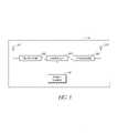
- FIG. 1shows an sensor system that includes a plurality of sensor units that communicate with a base unit through a number of repeater units.
- FIG. 2is a block diagram of a sensor unit.
- FIG. 3is a block diagram of a repeater unit.
- FIG. 4is a block diagram of the base unit.
- FIG. 5shows one embodiment a network communication packet used by the sensor units, repeater units, and the base unit.
- FIG. 6is a flowchart showing operation of a sensor unit that provides relatively continuous monitoring.
- FIG. 7is a flowchart showing operation of a sensor unit that provides periodic monitoring.
- FIG. 8shows how the sensor system can be used to detected water leaks.
- FIG. 9Ashows a dual-sensor system wherein sensors are provided above and below a drain.
- FIG. 9Bshows a dual-sensor system wherein sensors are provided in a first position above a drain and in a second position below a drain, where the second sensor is positioned to provide an indication that the drain is not sufficiently handling the flow of water.
- FIG. 10Ashows a moisture sensor that includes probes placed at different levels to detect different water levels.
- FIG. 10Bshows a moisture sensor that includes multiple probes made of varying materials and placed at different levels to detect different water levels.
- FIG. 10Cshows a moisture sensor that includes multiple probes provided to a substrate and configured to detect different water levels.
- FIG. 10Dshows a moisture sensor that includes multiple probes provided to a substrate and configured to detect different water levels, and where a chemical agent is provided to the substrate to aid in measurement of the water level.
- FIG. 10Eshows a moisture sensor that includes probes placed at different levels to detect different water levels and a pad to aid in detection of water.
- FIG. 10Fshows a moisture sensor that includes probes placed at different levels to detect different water levels and multiple pads to aid in detection of water.
- FIG. 11shows a sensor system similar to that shown in FIG. 8 , and wherein a moisture sensor is provided around a water tank.
- FIG. 12shows a sensor system wherein relatively low-cost sensors provide sensor readings and/or status information to an area monitor that communicates with a base unit.
- FIG. 13shows a moisture sensor unit with a self-test system.
- FIG. 14shows a smoke sensor with a self-test system.
- FIG. 1shows an sensor system 100 that includes a plurality of sensor units 102 - 106 that communicate with a base unit 112 through a number of repeater units 110 - 111 .
- the sensor units 102 - 106are located throughout a building 101 .
- Sensor units 102 - 104communicate with the repeater 110 .
- Sensor units 105 - 105communicate with the repeater 111 .
- the repeaters 110 - 111communicate with the base unit 112 .
- the base unit 112communicates with a monitoring computer system 113 through a computer network connection such as, for example, Ethernet, wireless Ethernet, firewire port, Universal Serial Bus (USB) port, bluetooth, etc.
- USBUniversal Serial Bus
- the computer system 113contacts a building manager, maintenance service, alarm service, or other responsible personnel 120 using one or more of several communication systems such as, for example, telephone 121 , pager 122 , cellular telephone 123 (e.g., direct contact, voicemail, text, etc.), and/or through the Internet and/or local area network 124 (e.g., through email, instant messaging, network communications, etc.).
- multiple base units 112are provided to the monitoring computer 113 .
- the monitoring computer 113is provided to more than one computer monitor, thus allowing more data to be displayed than can conveniently be displayed on a single monitor.
- the monitoring computer 113is provided to multiple monitors located in different locations, thus allowing the data form the monitoring computer 113 to be displayed in multiple locations.
- the sensor units 102 - 106include sensors to measure conditions, such as, for example, smoke, temperature, moisture, water, water temperature, humidity, carbon monoxide, natural gas, propane gas, security alarms, intrusion alarms (e.g., open doors, broken windows, open windows, and the like), other flammable gases, radon, poison gasses, etc.
- Different sensor unitscan be configured with different sensors or with combinations of sensors.
- the sensor units 102 and 104could be configured with smoke and/or temperature sensors while the sensor unit 103 could be configured with a humidity sensor.
- the discussion that followsgenerally refers to the sensor unit 102 as an example of a sensor unit, with the understanding that the description of the sensor unit 102 can be applied to many sensor units.
- the discussiongenerally refers to the repeater 110 by way of example, and not limitation. It will also be understood by one of ordinary skill in the art that repeaters are useful for extending the range of the sensor units 102 - 106 but are not required in all embodiments. Thus, for example in one embodiment, one or more of the sensor units 102 - 106 can communicate directly with the bast unit 112 without going through a repeater. It will also be understood by one of ordinary skill in the art that FIG.
- FIG. 1shows only five sensor units ( 102 - 106 ) and two repeater units ( 110 - 111 ) for purposes of illustration and not by way of limitation.
- An installation in a large apartment building or complexwould typically involve many sensor units and repeater units.
- one repeater unitcan service relatively many sensor units.
- the sensor units 102can communicate directly with the base unit 112 without going through a repeater 111 .
- the sensor unit 102When the sensor unit 102 detects an anomalous condition (e.g., smoke, fire, water, etc.) the sensor unit communicates with the appropriate repeater unit 110 and provides data regarding the anomalous condition.
- the repeater unit 110forwards the data to the base unit 112 , and the base unit 112 forwards the information to the computer 113 .
- the computer 113evaluates the data and takes appropriate action. If the computer 113 determines that the condition is an emergency (e.g., fire, smoke, large quantities of water), then the computer 113 contacts the appropriate personnel 120 . If the computer 113 determines that a the situation warrants reporting, but is not an emergency, then the computer 113 logs the data for later reporting. In this way, the sensor system 100 can monitor the conditions in and around the building 101 .
- an emergencye.g., fire, smoke, large quantities of water
- the sensor unit 102has an internal power source (e.g., battery, solar cell, fuel cell, etc.). In order to conserve power, the sensor unit 102 is normally placed in a low-power mode. In one embodiment, using sensors that require relatively little power, while in the low power mode the sensor unit 102 takes regular sensor readings and evaluates the readings to determine if an anomalous condition exists. In one embodiment, using sensors that require relatively more power, while in the low power mode the sensor unit 102 takes and evaluates sensor readings at periodic intervals. If an anomalous condition is detected, then the sensor unit 102 “wakes up” and begins communicating with the base unit 112 through the repeater 110 .
- an internal power sourcee.g., battery, solar cell, fuel cell, etc.
- the sensor unit 102also “wakes up” and sends status information (e.g., power levels, self diagnostic information, etc.) to the base unit (or repeater) and then listens for commands for a period of time.
- the sensor unit 102also includes a tamper detector. When tampering with the sensor unit 102 is detected, the sensor unit 102 reports such tampering to the base unit 112 .
- the sensor unit 102provides bi-directional communication and is configured to receive data and/or instructions from the base unit 112 .
- the base unit 112can instruct the sensor unit 102 to perform additional measurements, to go to a standby mode, to wake up, to report battery status, to change wake-up interval, to run self-diagnostics and report results, etc.
- the sensor unit 102reports its general health and status on a regular basis (e.g., results of self-diagnostics, battery health, etc.)
- the sensor unit 102provides two wake-up modes, a first wake-up mode for taking measurements (and reporting such measurements if deemed necessary), and a second wake-up mode for listening for commands from the central reporting station.
- the two wake-up modes, or combinations thereof,can occur at different intervals.
- the sensor unit 102use spread-spectrum techniques to communicate with the repeater unit 110 . In one embodiment, the sensor unit 102 use frequency-hopping spread-spectrum. In one embodiment, the sensor unit 102 has an address or identification (ID) code that distinguishes the sensor unit 102 from the other sensor units. The sensor unit 102 attaches its ID to outgoing communication packets so that transmissions from the sensor unit 102 can be identified by the repeater 110 . The repeater 110 attaches the ID of the sensor unit 102 to data and/or instructions that are transmitted to the sensor unit 102 . In one embodiment, the sensor unit 102 ignores data and/or instructions that are addressed to other sensor units.
- IDaddress or identification
- the sensor unit 102includes a reset function.
- the reset functionis activated by the reset switch 208 .
- the reset functionis active for a prescribed interval of time.
- the transceiver 203is in a receiving mode and can receive the identification code from an external programmer.
- the external programmerwirelessly transmits a desired identification code.
- the identification codeis programmed by an external programmer that is connected to the sensor unit 102 through an electrical connector.
- the electrical connection to the sensor unit 102is provided by sending modulated control signals (power line carrier signals) through a connector used to connect the power source 206 .
- the external programmerprovides power and control signals.
- the external programmeralso programs the type of sensor(s) installed in the sensor unit.
- the identification codeincludes an area code (e.g., apartment number, zone number, floor number, etc.) and a unit number (e.g., unit 1, 2, 3, etc.).
- the external programmerinterfaces with the controller 202 by using an optional programming interface 210 .
- the programming interface 210includes a connector.
- the programming interface 210includes an infrared interface.
- the programming interface 210includes an inductive coupling coil.
- the programming interface 210includes one or more capacitive coupling plates.
- the senorcommunicates with the repeater on the 900 MHz band. This band provides good transmission through walls and other obstacles normally found in and around a building structure. In one embodiment, the sensor communicates with the repeater on bands above and/or below the 900 MHz band. In one embodiment, the sensor, repeater, and/or base unit listen to a radio frequency channel before transmitting on that channel or before beginning transmission. If the channel is in use, (e.g., by another devise such as another repeater, a cordless telephone, etc.) then the sensor, repeater, and/or base unit changes to a different channel.
- the senor, repeater, and/or base unitcoordinate frequency hopping by listening to radio frequency channels for interference and using an algorithm to select a next channel for transmission that avoids the interference.
- the sensorwill test (e.g., listen to) the channel before transmission to avoid channels that are blocked, in use, or jammed.
- the sensorcontinues to transmit data until it receives an acknowledgement from the base unit that the message has been received.
- the sensortransmits data having a normal priority (e.g., status information) and does not look for an acknowledgement, and the sensor transmits data having elevated priority (e.g., excess smoke, temperature, etc.) until an acknowledgement is received.
- a normal prioritye.g., status information
- elevated prioritye.g., excess smoke, temperature, etc.
- the repeater unit 110is configured to relay communications traffic between the sensor 102 (and, similarly, the sensor units 103 - 104 ) and the base unit 112 .
- the repeater unit 110typically operates in an environment with several other repeater units (such as the repeater unit 111 in FIG. 1 ) and thus the repeater unit 110 contains a database (e.g., a lookup table) of sensor unit IDs.
- the repeater 110has database entries for the Ids of the sensors 102 - 104 , and thus the sensor 110 will only communicate with sensor units 102 - 104 .
- the repeater 110has an internal power source (e.g., battery, solar cell, fuel cell, etc.) and conserves power by maintaining an internal schedule of when the sensor units 102 - 104 are expected to transmit. In one embodiment, the repeater unit 110 goes to a low-power mode when none of its designated sensor units is scheduled to transmit. In one embodiment, the repeater 110 uses spread-spectrum techniques to communicate with the base unit 112 and with the sensor units 102 - 104 . In one embodiment, the repeater 110 uses frequency-hopping spread-spectrum to communicate with the base unit 112 and the sensor units 102 - 104 .
- an internal power sourcee.g., battery, solar cell, fuel cell, etc.
- the repeater unit 110has an address or identification (ID) code and the repeater unit 110 attaches its address to outgoing communication packets that originate in the repeater (that is, packets that are not being forwarded). In one embodiment, the repeater unit 110 ignores data and/or instructions that are addressed to other repeater units or to sensor units not serviced by the repeater 110 .
- IDaddress or identification
- the base unit 112communicates with the sensor unit 102 by transmitting a communication packet addressed to the sensor unit 102 .
- the repeaters 110 and 111both receive the communication packet addressed to the sensor unit 102 .
- the repeater unit 111ignores the communication packet addressed to the sensor unit 102 .
- the repeater unit 110transmits the communication packet addressed to the sensor unit 102 to the sensor unit 102 .
- the sensor unit 102 , the repeater unit 110 , and the base unit 112communicate using Frequency-Hopping Spread Spectrum (FHSS), also known as channel-hopping.
- FHSSFrequency-Hopping Spread Spectrum
- Frequency-hopping wireless systemsoffer the advantage of avoiding other interfering signals and avoiding collisions. Moreover, there are regulatory advantages given to systems that do not transmit continuously at one frequency. Channel-hopping transmitters change frequencies after a period of continuous transmission, or when interference is encountered. These systems may have higher transmit power and relaxed limitations on in-band spurs. FCC regulations limit transmission time on one channel to 400 milliseconds (averaged over 10-20 seconds depending on channel bandwidth) before the transmitter must change frequency. There is a minimum frequency step when changing channels to resume transmission. If there are 25 to 49 frequency channels, regulations allow effective radiated power of 24 dBm, spurs must be ⁇ 20 dBc, and harmonics must be ⁇ 41.2 dBc. With 50 or more channels, regulations allow effective radiated power to be up to 30 dBm.
- the sensor unit 102 , the repeater unit 110 , and the base unit 112communicate using FHSS wherein the frequency hopping of the sensor unit 102 , the repeater unit 110 , and the base unit 112 are not synchronized such that at any given moment, the sensor unit 102 and the repeater unit 110 are on different channels.
- the base unit 112communicates with the sensor unit 102 using the hop frequencies synchronized to the repeater unit 110 rather than the sensor unit 102 .
- the repeater unit 110then forwards the data to the sensor unit using hop frequencies synchronized to the sensor unit 102 .
- Such a systemlargely avoids collisions between the transmissions by the base unit 112 and the repeater unit 110 .
- the sensor units 102 - 106all use FHSS and the sensor units 102 - 106 are not synchronized. Thus, at any given moment, it is unlikely that any two or more of the sensor units 102 - 106 will transmit on the same frequency. In this manner, collisions are largely avoided. In one embodiment, collisions are not detected but are tolerated by the system 100 . If a collisions does occur, data lost due to the collision is effectively re-transmitted the next time the sensor units transmit sensor data. When the sensor units 102 - 106 and repeater units 110 - 111 operate in asynchronous mode, then a second collision is highly unlikely because the units causing the collisions have hopped to different channels.
- the sensor units 102 - 106 , repeater units 110 - 110 , and the base unit 112use the same hop rate. In one embodiment, the sensor units 102 - 106 , repeater units 110 - 110 , and the base unit 112 use the same pseudo-random algorithm to control channel hopping, but with different starting seeds. In one embodiment, the starting seed for the hop algorithm is calculated from the ID of the sensor units 102 - 106 , repeater units 110 - 110 , or the base unit 112 .
- the base unitcommunicates with the sensor unit 102 by sending a communication packet addressed to the repeater unit 110 , where the packet sent to the repeater unit 110 includes the address of the sensor unit 102 .
- the repeater unit 102extracts the address of the sensor unit 102 from the packet and creates and transmits a packet addressed to the sensor unit 102 .
- the repeater unit 110is configured to provide bi-directional communication between its sensors and the base unit 112 .
- the repeater 110is configured to receive instructions from the base unit 110 .
- the base unit 112can instruct the repeater to: send commands to one or more sensors; go to standby mode; “wake up”; report battery status; change wake-up interval; run self-diagnostics and report results; etc.
- the base unit 112is configured to receive measured sensor data from a number of sensor units either directly, or through the repeaters 110 - 111 .
- the base unit 112also sends commands to the repeater units 110 - 111 and/or to the sensor units 110 - 111 .
- the base unit 112communicates with a diskless computer 113 that runs off of a CD-ROM.
- the base unit 112receives data from a sensor unit 102 - 111 indicating that there may be an emergency condition (e.g., a fire or excess smoke, temperature, water, etc.) the computer 113 will attempt to notify the responsible party 120 .
- an emergency conditione.g., a fire or excess smoke, temperature, water, etc.
- the computer 112maintains a database of the health, power status (e.g., battery charge), and current operating status of all of the sensor units 102 - 106 and the repeater units 110 - 111 .
- the computer 113automatically performs routine maintenance by sending commands to each sensor unit 102 - 106 to run a self-diagnostic and report the results. The computer 113 collects and logs such diagnostic results.
- the computer 113sends instructions to each sensor unit 102 - 106 telling the sensor how long to wait between “wakeup” intervals.
- the computer 113schedules different wakeup intervals to different sensor unit 102 - 106 based on the sensor unit's health, power status, location, etc.
- the computer 113schedules different wakeup intervals to different sensor unit 102 - 106 based on the type of data and urgency of the data collected by the sensor unit (e.g., sensor units that have smoke and/or temperature sensors produce data that should be checked relatively more often than sensor units that have humidity or moisture sensors).
- the base unitsends instructions to repeaters to route sensor information around a failed repeater.
- the computer 113produces a display that tells maintenance personnel which sensor units 102 - 106 need repair or maintenance. In one embodiment, the computer 113 maintains a list showing the status and/or location of each sensor according to the ID of each sensor.
- the sensor units 102 - 106 and/or the repeater units 110 - 111measure the signal strength of the wireless signals received (e.g., the sensor unit 102 measures the signal strength of the signals received from the repeater unit 110 , the repeater unit 110 measures the signal strength received from the sensor unit 102 and/or the base unit 112 ).
- the sensor units 102 - 106 and/or the repeater units 110 - 111report such signal strength measurement back to the computer 113 .
- the computer 113evaluates the signal strength measurements to ascertain the health and robustness of the sensor system 100 .
- the computer 113uses the signal strength information to re-route wireless communications traffic in the sensor system 100 .
- the computer 113can send instructions to the repeater unit 111 to add the ID of the sensor unit 102 to the database of the repeater unit 111 (and similarly, send instructions to the repeater unit 110 to remove the ID of the sensor unit 102 ), thereby routing the traffic for the sensor unit 102 through the router unit 111 instead of the router unit 110 .
- FIG. 2is a block diagram of the sensor unit 102 .
- the sensor unit 102one or more sensors 201 and a transceiver 203 are provided to a controller 202 .
- the controller 202typically provides power, data, and control information to the sensor(s) 201 and the transceiver 202 .
- a power source 206is provided to the controller 202 .
- An optional tamper sensor 205is also provided to the controller 202 .
- a reset device (e.g., a switch) 208is proved to the controller 202 .
- an optional audio output device 209is provided.
- the sensor 201is configured as a plug-in module that can be replaced relatively easily.
- the transceiver 203is based on a TRF 6901 transceiver chip from Texas Instruments. Inc.
- the controller 202is a conventional programmable microcontroller.
- the controller 202is based on a Field Programmable Gate Array (FPGA), such as, for example, provided by Xilinx Corp.
- the sensor 201includes an optoelectric smoke sensor with a smoke chamber.
- the sensor 201includes a thermistor.
- the sensor 201includes a humidity sensor.
- the sensor 201includes an sensor, such as, for example, a water level sensor, a water temperature sensor, a carbon monoxide sensor, a moisture sensor, a water flow sensor, natural gas sensor, propane sensor, etc.
- the controller 202receives sensor data from the sensor(s) 201 . Some sensors 201 produce digital data. However, for many types of sensors 201 , the sensor data is analog data. Analog sensor data is converted to digital format by the controller 202 . In one embodiment, the controller evaluates the data received from the sensor(s) 201 and determines whether the data is to be transmitted to the base unit 112 . The sensor unit 102 generally conserves power by not transmitting data that falls within a normal range. In one embodiment, the controller 202 evaluates the sensor data by comparing the data value to a threshold value (e.g., a high threshold, a low threshold, or a high-low threshold).
- a threshold valuee.g., a high threshold, a low threshold, or a high-low threshold
- the data thresholdis programmed into the controller 202 .
- the data thresholdis programmed by the base unit 112 by sending instructions to the controller 202 .
- the controller 202obtains sensor data and transmits the data when commanded by the computer 113 .
- the tamper sensor 205is configured as a switch that detects removal of or tampering with the sensor unit 102 .
- FIG. 3is a block diagram of the repeater unit 110 .
- a first transceiver 302 and a second transceiver 305are provided to a controller 303 .
- the controller 303typically provides power, data, and control information to the transceivers 302 , 304 .
- a power source 306is provided to the controller 303 .
- An optional tamper sensor(not shown) is also provided to the controller 303 .
- the controller 303When relaying sensor data to the base unit 112 , the controller 303 receives data from the first transceiver 303 and provides the data to the second transceiver 304 . When relaying instructions from the base unit 112 to a sensor unit, the controller 303 receives data from the second transceiver 304 and provides the data to the first transceiver 302 . In one embodiment, the controller 303 conserves power by powering-down the transceivers 302 , 304 during periods when the controller 303 is not expecting data. The controller 303 also monitors the power source 306 and provides status information, such as, for example, self-diagnostic information and/or information about the health of the power source 306 , to the base unit 112 .
- status informationsuch as, for example, self-diagnostic information and/or information about the health of the power source 306
- the controller 303sends status information to the base unit 112 at regular intervals. In one embodiment, the controller 303 sends status information to the base unit 112 when requested by the base unit 112 . In one embodiment, the controller 303 sends status information to the base unit 112 when a fault condition (e.g., battery low) is detected.
- a fault conditione.g., battery low
- the controller 303includes a table or list of identification codes for wireless sensor units 102 .
- the repeater 303forwards packets received from, or sent to, sensor units 102 in the list.
- the repeater 110receives entries for the list of sensor units from the computer 113 .
- the controller 303determines when a transmission is expected from the sensor units 102 in the table of sensor units and places the repeater 110 (e.g., the transceivers 302 , 304 ) in a low-power mode when no transmissions are expected from the transceivers on the list.
- the controller 303recalculates the times for low-power operation when a command to change reporting interval is forwarded to one of the sensor units 102 in the list (table) of sensor units or when a new sensor unit is added to the list (table) of sensor units.
- FIG. 4is a block diagram of the base unit 112 .
- a transceiver 402 and a computer interface 404are provided to a controller 403 .
- the controller 303typically provides data and control information to the transceivers 402 and to the interface.
- the interface 402is provided to a port on the monitoring computer 113 .
- the interface 402can be a standard computer data interface, such as, for example, Ethernet, wireless Ethernet, firewire port, Universal Serial Bus (USB) port, bluetooth, etc.
- USBUniversal Serial Bus
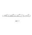
- FIG. 5shows one embodiment a communication packet 500 used by the sensor units, repeater units, and the base unit.
- the packet 500includes a preamble portion 501 , an address (or ID) portion 502 , a data payload portion 503 , and an integrity portion 504 .
- the integrity portion 504includes a checksum.
- the sensor units 102 - 106 , the repeater units 110 - 111 , and the base unit 112communicate using packets such as the packet 500 .
- the packets 500are transmitted using FHSS.
- the data packets that travel between the sensor unit 102 , the repeater unit 111 , and the base unit 112are encrypted. In one embodiment, the data packets that travel between the sensor unit 102 , the repeater unit 111 , and the base unit 112 are encrypted and an authentication code is provided in the data packet so that the sensor unit 102 , the repeater unit, and/or the base unit 112 can verify the authenticity of the packet.
- the address portion 502includes a first code and a second code.
- the repeater 111only examines the first code to determine if the packet should be forwarded.
- the first codecan be interpreted as a building (or building complex) code and the second code interpreted as a subcode (e.g., an apartment code, area code, etc.).
- a repeater that uses the first code for forwardingthus forwards packets having a specified first code (e.g., corresponding to the repeater's building or building complex).
- a repeater so configuredonly needs to know the first code to forward packets for any repeater in the building or building complex. This does, however, raise the possibility that two repeaters in the same building could try to forward packets for the same sensor unit 102 .
- each repeaterwaits for a programmed delay period before forwarding a packet. Thus reducing the chance of packet collisions at the base unit (in the case of sensor unit to base unit packets) and reducing the chance of packet collisions at the sensor unit (in the case of base unit to sensor unit packets).
- a delay periodis programmed into each repeater. In one embodiment, delay periods are pre-programmed onto the repeater units at the factory or during installation.
- a delay periodis programmed into each repeater by the base unit 112 .
- a repeaterrandomly chooses a delay period.
- a repeaterrandomly chooses a delay period for each forwarded packet.
- the first codeis at least 6 digits.
- the second codeis at least 5 digits.
- the first code and the second codeare programmed into each sensor unit at the factory. In one embodiment, the first code and the second code are programmed when the sensor unit is installed. In one embodiment, the base unit 112 can re-program the first code and/or the second code in a sensor unit.
- collisionsare further avoided by configuring each repeater unit 111 to begin transmission on a different frequency channel.
- each repeater unit 111configuring each repeater unit 111 to begin transmission on a different frequency channel.
- FIG. 6is a flowchart showing one embodiment of the operation of the sensor unit 102 wherein relatively continuous monitoring is provided.
- a power up block 601is followed by an initialization block 602 .
- the sensor unit 102checks for a fault condition (e.g., activation of the tamper sensor, low battery, internal fault, etc.) in a block 603 .
- a decision block 604checks the fault status. If a fault has occurred, then the process advances to a block 605 were the fault information is transmitted to the repeater 110 (after which, the process advances to a block 612 ); otherwise, the process advances to a block 606 .
- the sensor unit 102takes a sensor reading from the sensor(s) 201 .
- the sensor datais subsequently evaluated in a block 607 . If the sensor data is abnormal, then the process advances to a transmit block 609 where the sensor data is transmitted to the repeater 110 (after which, the process advances to a block 612 ); otherwise, the process advances to a timeout decision block 610 . If the timeout period has not elapsed, then the process returns to the fault-check block 603 ; otherwise, the process advances to a transmit status block 611 where normal status information is transmitted to the repeater 110 .
- the normal status information transmittedis analogous to a simple “ping” which indicates that the sensor unit 102 is functioning normally.
- transceiver 203is normally powered down.
- the controller 202powers up the transceiver 203 during execution of the blocks 605 , 609 , 611 , and 612 .
- the monitoring computer 113can send instructions to the sensor unit 102 to change the parameters used to evaluate data used in block 607 , the listen period used in block 612 , etc.
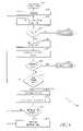
- FIG. 7is a flowchart showing one embodiment of operation of the sensor unit 102 wherein periodic monitoring is provided.
- a power up block 701is followed by an initialization block 702 . After initialization, the sensor unit 102 enters a low-power sleep mode.
- the processenters a wake-up block 704 followed by a transmit fault block 705 . If no fault occurs during the sleep period, then when the specified sleep period has expired, the process enters a block 706 where the sensor unit 102 takes a sensor reading from the sensor(s) 201 . The sensor data is subsequently sent to the monitoring computer 113 in a report block 707 . After reporting, the sensor unit 102 enters a listen block 708 where the sensor unit 102 listens for a relatively short period of time for instructions from monitoring computer 708 . If an instruction is received, then the sensor unit 102 performs the instructions, otherwise, the process returns to the sleep block 703 .
- a faultoccurs during the sleep mode (e.g., the tamper sensor is activated)
- the processenters a wake-up block 704 followed by a transmit fault block 705 . If no fault occurs during the sleep period, then when the specified sleep period has expired, the process enters a block 706 where the sensor unit 102 takes a sensor reading from
- the senor 201 and transceiver 203are normally powered down.
- the controller 202powers up the sensor 201 during execution of the block 706 .
- the controller 202powers up the transceiver during execution of the blocks 705 , 707 , and 708 .
- the monitoring computer 113can send instructions to the sensor unit 102 to change the sleep period used in block 703 , the listen period used in block 708 , etc.
- the sensor unittransmits sensor data until a handshaking-type acknowledgement is received.
- the sensor unit 102retransmits its data and waits for an acknowledgement.
- the sensor unit 102continues to transmit data and wait for an acknowledgement until an acknowledgement is received.
- the sensor unitaccepts an acknowledgement from a repeater unit 111 and it then becomes the responsibility of the repeater unit 111 to make sure that the data is forwarded to the base unit 112 .
- the repeater unit 111does not generate the acknowledgement, but rather forwards an acknowledgement from the base unit 112 to the sensor unit 102 .
- the two-way communication ability of the sensor unit 102provides the capability for the base unit 112 to control the operation of the sensor unit 102 and also provides the capability for robust handshaking-type communication between the sensor unit 102 and the base unit 112 .
- the monitoring computer 113can instruct the sensor unit 102 to operate in a relatively continuous mode where the sensor repeatedly takes sensor readings and transmits the readings to the monitoring computer 113 .
- a relatively continuous modewhere the sensor repeatedly takes sensor readings and transmits the readings to the monitoring computer 113 .
- Such a modewould can be used, for example, when the sensor unit 102 (or a nearby sensor unit) has detected a potentially dangerous condition (e.g., smoke, rapid temperature rise, etc.)
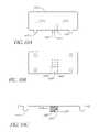
- FIG. 8shows the sensor system used to detect water leaks.
- the sensor unit 102includes a water level sensor 803 and/or a water temperature sensor 804 .
- the water level sensor 803 and/or water temperature sensor 804are place, for example, in a tray underneath a water heater 801 in order to detect leaks from the water heater 801 and thereby prevent water damage from a leaking water heater.
- an temperature sensoris also provide to measure temperature near the water heater.
- the water level sensorcan also be placed under a sink, in a floor sump, etc.
- the severity of a leakis ascertained by the sensor unit 102 (or the monitoring computer 113 ) by measuring the rate of rise in the water level.
- the severity of a leakcan also be ascertained at least in part by measuring the temperature of the water.
- a first water flow sensoris placed in an input water line for the hot water tank 801 and a second water flow sensor is placed in an output water line for the hot water tank. Leaks in the tank can be detected by observing a difference between the water flowing through the two sensors.
- a remote shutoff valve 810is provided, so that the monitoring system 100 can shutoff the water supply to the water heater when a leak is detected.
- the shutoff valveis controlled by the sensor unit 102 .
- the sensor unit 102receives instructions from the base unit 112 to shut off the water supply to the heater 801 .
- the responsible party 120sends instructions to the monitoring computer 113 instructing the monitoring computer 113 to send water shut off instructions to the sensor unit 102 .
- the sensor unit 102controls a gas shutoff valve 811 to shut off the gas supply to the water heater 801 and/or to a furnace (not shown) when dangerous conditions (such as, for example, gas leaks, carbon monoxide, etc.) are detected.
- a gas detector 812is provided to the sensor unit 102 .
- the gas detector 812measures carbon monoxide.
- the gas detector 812measures flammable gas, such as, for example, natural gas or propane.
- an optional temperature sensor(not shown) is provided to measure stack temperature. Using data from the stack temperature sensor , the sensor unit 102 reports conditions, such as, for example, excess stack temperature. Excess stack temperature is often indicative of poor heat transfer (and thus poor efficiency) in the water heater 801 .
- an optional temperature sensor 819is provided to measure temperature of water in the water heater 801 . Using data from the temperature sensor 819 , the sensor unit 102 reports conditions, such as, for example, over-temperature or under-temperature of the water in the water heater.
- an optional current probe 821is provided to measure electric current provided to a heating element 820 in an electric water heater.
- the sensor unit 102uses data from the current probe 821 to report conditions, such as, for example, no current (indicating a burned-out heating element 820 ).
- An over-current conditionoften indicates that the heating element 820 is encrusted with mineral deposits and needs to be replaced or cleaned.
- the monitoring systemcan measure the amount of energy provided to the water heater and thus the cost of hot water, and the efficiency of the water heater.
- the senor 803includes a moisture sensor. Using data from the moisture sensor, the sensor unit 102 reports moisture conditions, such as, for example, excess moisture that would indicate a water leak, excess condensation, etc.
- the sensor unit 102is provided to a moisture sensor (such as the sensor 803 ) located near an air conditioning unit. Using data from the moisture sensor, the sensor unit 102 reports moisture conditions, such as, for example, excess moisture that would indicate a water leak, excess condensation, etc.
- the senor 201includes a moisture sensor.
- the moisture sensorcan be place under a sink or a toilet (to detect plumbing leaks) or in an attic space (to detect roof leaks).
- the sensor 201includes a humidity sensor.
- the humidity sensorcan be place under a sink, in an attic space, etc. to detect excess humidity (due to leaks, condensation, etc.).
- the monitoring computer 113compares humidity measurements taken from different sensor units in order to detect areas that have excess humidity. Thus for example, the monitoring computer 113 can compare the humidity readings from a first sensor unit 102 in a first attic area, to a humidity reading from a second sensor unit 102 in a second area.
- the monitoring computercan take humidity readings from a number of attic areas to establish a baseline humidity reading and then compare the specific humidity readings from various sensor units to determine if one or more of the units are measuring excess humidity.
- the monitoring computer 113would flag areas of excess humidity for further investigation by maintenance personnel.
- the monitoring computer 113maintains a history of humidity readings for various sensor units and flags areas that show an unexpected increase in humidity for investigation by maintenance personnel.
- the monitoring system 100detects conditions favorable for fungus (e.g., mold, mildew, fungus, etc.) growth by using a first humidity sensor located in a first building area to produce first humidity data and a second humidity sensor located in a second building area to produce second humidity data.
- the building areascan be, for example, areas near a sink drain, plumbing fixture, plumbing, attic areas, outer walls, a bilge area in a boat, etc.
- the monitoring station 113collects humidity readings from the first humidity sensor and the second humidity sensor and indicates conditions favorable for fungus growth by comparing the first humidity data and the second humidity data. In one embodiment, the monitoring station 113 establishes a baseline humidity by comparing humidity readings from a plurality of humidity sensors and indicates possible fungus growth conditions in the first building area when at least a portion of the first humidity data exceeds the baseline humidity by a specified amount. In one embodiment, the monitoring station 113 establishes a baseline humidity by comparing humidity readings from a plurality of humidity sensors and indicates possible fungus growth conditions in the first building area when at least a portion of the first humidity data exceeds the baseline humidity by a specified percentage.
- the monitoring station 113establishes a baseline humidity history by comparing humidity readings from a plurality of humidity sensors and indicates possible fungus growth conditions in the first building area when at least a portion of the first humidity data exceeds the baseline humidity history by a specified amount over a specified period of time. In one embodiment, the monitoring station 113 establishes a baseline humidity history by comparing humidity readings from a plurality of humidity sensors over a period of time and indicates possible fungus growth conditions in the first building area when at least a portion of the first humidity data exceeds the baseline humidity by a specified percentage of a specified period of time.
- the sensor unit 102transmits humidity data when it determines that the humidity data fails a threshold test.
- the humidity threshold for the threshold testis provided to the sensor unit 102 by the monitoring station 113 .
- the humidity threshold for the threshold testis computed by the monitoring station from a baseline humidity established in the monitoring station.
- the baseline humidityis computed at least in part as an average of humidity readings from a number of humidity sensors.
- the baseline humidityis computed at least in part as a time average of humidity readings from a number of humidity sensors.
- the baseline humidityis computed at least in part as a time average of humidity readings from a humidity sensor.
- the baseline humidityis computed at least in part as the lesser of a maximum humidity reading an average of a number of humidity readings.
- the sensor unit 102reports humidity readings in response to a query by the monitoring station 113 . In one embodiment, the sensor unit 102 reports humidity readings at regular intervals. In one embodiment, a humidity interval is provided to the sensor unit 102 by the monitoring station 113 .
- the calculation of conditions for fungus growthis comparing humidity readings from one or more humidity sensors to the baseline (or reference) humidity. In one embodiment, the comparison is based on comparing the humidity readings to a percentage (e.g., typically a percentage greater than 100%) of the baseline value. In one embodiment, the comparison is based on comparing the humidity readings to a specified delta value above the reference humidity. In one embodiment, the calculation of likelihood of conditions for fungus growth is based on a time history of humidity readings, such that the longer the favorable conditions exist, the greater the likelihood of fungus growth. In one embodiment, relatively high humidity readings over a period of time indicate a higher likelihood of fungus growth than relatively high humidity readings for short periods of time.
- a relatively sudden increase in humidity as compared to a baseline or reference humidityis reported by the monitoring station 113 as a possibility of a water leak. If the relatively high humidity reading continues over time then the relatively high humidity is reported by the monitoring station 113 as possibly being a water leak and/or an area likely to have fungus growth or water damage.
- Temperatures relatively more favorable to fungus growthincrease the likelihood of fungus growth.
- temperature measurements from the building areasare also used in the fungus grown-likelihood calculations.
- a threshold value for likelihood of fungus growthis computed at least in part as a function of temperature, such that temperatures relatively more favorable to fungus growth result in a relatively lower threshold than temperatures relatively less favorable for fungus growth.
- the calculation of a likelihood of fungus growthdepends at least in part on temperature such that temperatures relatively more favorable to fungus growth indicate a relatively higher likelihood of fungus growth than temperatures relatively less favorable for fungus growth.
- a maximum humidity and/or minimum threshold above a reference humidityis relatively lower for temperature more favorable to fungus growth than the maximum humidity and/or minimum threshold above a reference humidity for temperatures relatively less favorable to fungus growth.
- a water flow sensoris provided to the sensor unit 102 .
- the sensor unit 102obtains water flow data from the water flow sensor and provides the water flow data to the monitoring computer 113 .
- the monitoring computer 113can then calculate water usage. Additionally, the monitoring computer can watch for water leaks, by, for example, looking for water flow when there should be little or no flow. Thus, for example, if the monitoring computer detects water usage throughout the night, the monitoring computer can raise an alert indicating that a possible water leak has occurred.
- the sensor 201includes a water flow sensor is provided to the sensor unit 102 .
- the sensor unit 102obtains water flow data from the water flow sensor and provides the water flow data to the monitoring computer 113 .
- the monitoring computer 113can then calculate water usage. Additionally, the monitoring computer can watch for water leaks, by, for example, looking for water flow when there should be little or no flow. Thus, for example, if the monitoring computer detects water usage throughout the night, the monitoring computer can raise an alert indicating that a possible water leak has occurred.
- the sensor 201includes a fire-extinguisher tamper sensor is provided to the sensor unit 102 .
- the fire-extinguisher tamper sensorreports tampering with or use of a fire-extinguisher.
- the fire-extinguisher temper sensorreports that the fire extinguisher has been removed from its mounting, that a fire extinguisher compartment has been opened, and/or that a safety lock on the fire extinguisher has been removed.
- FIG. 9Ashows a dual-sensor system wherein the tray 802 , as shown in FIG. 8 , includes a drain.
- a sensor 901is provided below the drain, and a sensor 902 is provided above the drain.
- the sensors 901 and 902are provided to the sensor unit 102 .
- a messageis sent from the sensor unit 102 to the base unit 112 indicating that the sensor 901 has detected water and the sensor 902 has not detected water.
- the monitoring system 113can then report that a leak has been detected, but that the leaking water is being routed to the drain.
- both the sensors 901 and 902detect water
- a messageis sent from the sensor unit 102 to the base unit 112 indicating that both the sensors 901 and 902 have detected water.
- the monitoring system 113can then report that a serious leak has been detected, and that the leaking water is being safely routed to the drain.
- the monitoring system 113can estimate the rate of rise in the water level by calculating the time difference between the time that the sensor 901 detects water and the time that the sensor 902 detects water.
- the sensor unit 102includes a timestamp to indicate when the sensor 901 and/or the sensor 902 begins to detect water.
- the sensor unit 102measures a time difference between the time the sensor 901 begins to detect water and the time the sensor 902 begins to detect water, and reports the time difference to the monitoring unit 113 .
- the monitoring unit 113computes the time difference between the detection by the sensor 901 and the sensor 902 by calculating the time difference between receipt of a first message from the sensor unit 102 reporting water detection by the sensor 901 and receipt of a second message from the sensor unit 102 reporting water detection by the sensor 902 .
- the size of the tray 802 and the size of the drainare provided to the monitoring unit 113 and/or the sensor unit 102 and the monitoring unit 113 and/or the sensor unit 102 calculates an estimate for the flow rate of the leak by using the time difference between detection by the sensors 901 , 902 , the size of the tray 802 , and the size of the drain.
- FIG. 9Bshows a dual-sensor system similar to FIG. 9A except that in FIG. 9B , the drain is out the bottom of the tray 802 instead of the side as show in FIG. 9A . Nevertheless, the system shown in FIG. 9B works in a manner similar to that of FIG. 9A .
- the sensor 901is located at or near the bottom of the tray 802 and the sensor 902 is located higher than the sensor 901 .
- a messageis sent from the sensor unit 102 to the base unit 112 indicating that the sensor 901 has detected water and the sensor 902 has not detected water.
- the monitoring system 113can then report that a leak has been detected, but that the leaking water is being routed to the drain. If, however, both the sensors 901 and 902 detect water, then a message is sent from the sensor unit 102 to the base unit 112 indicating that both the sensors 901 and 902 have detected water. The monitoring system 113 can then report that a serious leak has been detected, and that the leaking water is being safely routed to the drain. As described in connection with FIG. 9A , the time between detection of water by the sensors 901 and 902 , (and, optional, the size of the tray 802 and the drain) can be used to estimate the severity of the leak.
- FIG. 10Ashows a moisture sensor unit 1010 that includes probes 1020 and 1022 placed at different levels to detect different water levels.
- the moisture sensor unit 1010can be configured as one embodiment of the sensor unit 102 .
- the moisture sensor unit 1010can be configured as shown in FIG. 2 with a transceiver 203 that can both transmit and receive, or the transceiver 203 can be configured for transmit-only operation.
- the moisture sensor unit 1010includes a case with one or more feet 1011 to hold the case above a surface.
- a relatively longer probe 1020extends from the case to detect a first water level, and a relatively shorter probe 1022 extends from the case to detect a second water level.
- a common probe (e.g., a ground probe) 1021also extends from the case.
- the moisture sensor unit 1010reports a first water level when water completes a circuit between the probe 1020 and the common probe 1021 .
- the moisture sensor 1010reports a second water level when water completes a circuit between the probe 1022 and the common probe 1021 .
- the moisture sensor unit 1010measures a first electrical resistance between the first probe 1020 and the common probe 1021 and a second electrical resistance between the common probe 1021 and the second probe 1022 .
- the presence of wateris indicated by a drop in the first and/or second resistances.
- a drop in the first resistanceindicates a first water level.
- a drop the second resistanceindicates a second water level.
- the moisture sensor unit 1010indicates the presence of water with the first or second resistance falls below a threshold value.
- the sensor unit 1010reports the actual measured first and/or second resistance to the monitoring system 113 .
- the amount of wateris estimated by the value of the first and/or second resistance.
- the water rate of riseis estimated from the rate of change in the value of the first and or second resistances.
- the moisture sensor unit 1010measures a first galvanic voltage between the first probe 1020 and the common probe 1021 and a second galvanic voltage between the common probe 1021 and the second probe 1022 .
- the presence of a first and/or second galvanic voltageindicates the presence of water.
- the sensor unit 1010measures both the resistances between the probes 1020 - 1022 and the galvanic voltages between the probes 1020 - 1022 .
- the probes 1020 and 1022are configured from a different material (e.g., a different metal) than the common probe 1021 .
- FIG. 10Bshows a moisture sensor that includes multiple probes made of varying materials and placed at different levels to detect different water levels.
- a plurality of first probes 1020 , a second plurality of probes 1021 , and/or a second plurality of probes 1022are configured from conductive materials, such as, for example, copper, gold, platinum, carbon, conductive plastic, etc.
- the various probes 1020can be of the same material or different materials, and can include multiple materials in each probe (e.g., gold plating, platinum plating, etc.).
- the various probes 1021can be of the same material or different materials, and can include multiple materials in each probe (e.g., gold plating, platinum plating, etc.).
- the various probes 1022can be of the same material or different materials, and can include multiple materials in each probe (e.g., gold plating, platinum plating, etc.).
- FIG. 10Cshows a moisture sensor that includes the probes 1020 - 1022 provided to a substrate 1025 .
- the substrate 1025is a printed-circuit substrate and the probes 1020 - 1022 are configured using printed circuit processing techniques.
- FIG. 10Dshows a moisture sensor that includes the probes 1020 - 1022 provided to the substrate 1025 and configured to detect different water levels, wherein a chemical agent 1030 is provided to the substrate to aid in measurement of the water level.
- the chemical agentcan be configured as a conduction-enhancing agent that has a relatively high resistance when dry but a relatively lower resistance when wet, such as, for example, salts, acids, detergents, ionic compounds, etc.
- FIG. 10Eshows a moisture sensor that includes probes placed at different levels to detect different water levels and a pad 1031 to aid in detection of water.
- the pad 1031is provided to the probe 1020 and to the probe 1021 .
- a conduction-enhancing agentsuch as described above is provided to the pad 1031 .
- the pad 1031can also be made thick enough to be provided to the probe 1022 as well.
- FIG. 10Fshows a moisture sensor that includes the pad 1031 and a second pad 1032 .
- the pad 1032is provided to the probe 1021 and the probe 1022 (and, optionally) to the probe 1020 ).
- the pad 1031can be omitted in favor of the pad 1032 or both the pad 1031 and 132 can be provided.
- a conduction-enhancing agentsuch as described above can be provided to the pad 1031 , or the pad 1032 , or to both pads.
- a first conduction-enhancing agentsuch as described above is provided to the pad 1031
- a second conduction-enhancing agentis provided to the pad 1032 .
- FIG. 11shows a sensor system similar to that shown in FIG. 8 , and wherein a moisture sensor 1102 is provided around a water tank.
- the configuration shown in FIG. 11can be used in connection with the sensors shown in FIGS. 8 , 9 A, and 9 B.
- the sensor 1102can also be provided in configurations (e.g., older construction) where the tray 802 is not provided.
- the sensor 1102measure water on the side of the tank 801 due to leaks in the tank 801 or due to water running down the side of the tank 801 due to leaks in the plumbing connections to the tank 801 .
- FIG. 12shows a sensor system 1200 wherein one or more relatively low-cost sensor units 1202 - 1204 provide sensor readings and/or status information to an area monitor unit 1210 that communicates with the base unit 112 or with a repeater unit 110 .
- the sensor units 1202 - 1204can be configured as embodiments of the sensor unit 102 and/or as embodiments of the moisture sensor unit 1010 . In one embodiment, the sensor units 1202 and 1204 are configured for one-way communication to transmit information to the area monitor 1210 .
- the moisture sensor unit 1010can be configured as one embodiment of the sensor unit 102 .
- the moisture sensor unit 1010can be configured as shown in FIG. 2 with a transceiver 203 that can both transmit and receive, or the transceiver 203 can be configured for transmit-only operation.
- the area monitor 1210is configured in a manner similar to the repeater unit 110 .
- the area monitor 1210is configured to provide bi-directional communication with one or more sensor units 102 . In one embodiment, the area monitor 1210 is configured to receive one-way communication from one or more sensor units 1202 - 1204 .
- the sensor unit 1202sends a message to the area monitor 1210 whenever an anomalous sensor reading is detected (e.g., water is detected, smoke is detected, etc.). In one embodiment, the sensor unit 1202 sends a stream of messages spaced at desired intervals (e.g., every few seconds) to the area monitor 1210 whenever an anomalous sensor reading is detected. In one embodiment, the sensor unit 1202 sends a status report (e.g., system health, battery power status, etc.) to the area monitor 1210 at a desired regular interval (e.g., every hour, every day, every few hours, etc.). The area monitor forwards messages from the sensor system 1200 to the monitoring system 113 .
- an anomalous sensor readinge.g., water is detected, smoke is detected, etc.
- the sensor unit 1202sends a stream of messages spaced at desired intervals (e.g., every few seconds) to the area monitor 1210 whenever an anomalous sensor reading is detected.
- the sensor unit 1202sends a status report (e.
- the monitoring system 113 and/or area monitor 1210can determine that the sensor unit 1202 has failed based on status information received from the sensor unit 1202 and/or based on a lack of status information from the sensor unit 1202 .
- the area monitor 1210expects to receive periodic status updates from the sensor 1202 , thus, the area monitor (and the central monitor 113 ) can assume that the sensor unit 1202 has failed or been removed if such regular status updates are not received.
- the sensor unit 1202send actual sensor data to the area monitor 1210 and the area monitor forwards such data to the central monitoring system 113 for analysis.
- the sensor units 1202 - 1204 and 102 - 106provide actual sensor readings that can be analyzed by the monitoring system to determine or estimate the severity of a problem (e.g., the amount of smoke, the amount of water, the rate of increase in smoke, water, temperature, etc.).
- the monitoring system 113maintains data received from the sensor units 1202 - 1204 and 102 - 106 to help in maintenance of the sensor system.
- maintenance personnelare expected to test each sensor unit on a regular basis (e.g., semi-annually, annually, bi-annually, monthly, etc.) to make sure the sensor is working.
- the maintenance personnelare expected to expose each moisture sensor 1010 to water to test the operation of the sensor and to make sure that a “water-sensed” message is transmitted to the monitoring system 113 .
- the maintenance personnelcan be tasked with exposing each smoke sensor to smoke.
- the monitoring system databaseshows that a particular sensor unit has not reported a sensor event (e.g., water detected, smoke detected, etc.) in a period corresponding to the maintenance interval
- the monitoring system 113can report that the sensor unit has failed or that the sensor unit has not been tested according to the testing schedule.
- supervisory personnelcan monitor the actions of maintenance personnel by examining the database maintained by the system 113 to make sure that each sensor has been activated and tested according the desired maintenance schedule.
- the database maintained by the monitoring system 113can also be used to provide plots of sensor activations and to indicate possible trouble areas in a building or structure. Thus, for example, if a particular water sensor has been activated on a regular basis, the monitoring system 113 can indicate that a potential problem exists in the area monitored by that sensor and thus, alert the maintenance or supervisory personnel.
- FIG. 13shows the moisture sensor unit 1010 provided with a self-test system that includes a container 1310 and an actuator 1303 .
- the container 1310is provided with a test fluid (e.g., water, alcohol mixture, solvent, etc.) configured to activate a sensor 1310 provided to the sensor unit 1010 (in one embodiment, the sensor 1310 includes the probes 1020 - 1022 shown in FIGS. 10A-F ).
- the actuatorreleases a portion of the fluid 1302 onto the sensor 1310 to test the sensor 1310 and the sensor unit 1010 .
- the actuator 1303includes a valve.
- the actuator 1303includes a pump.
- the actuator 1303includes an ultrasonic pump.
- the actuatoris provided to the controller 202 .
- the controller 202activates the actuator at periodic intervals according to a test schedule.
- the message constructed by the controller 202 and sent to the monitoring system 113includes a flag indicating that the actuator 1303 has been activated and that the sensor readings from the sensor should correspond to reading expected when the sensor 1310 is exposed to the fluid 1302 .
- the monitoring system 113can evaluate the sensor data from the sensor 1310 for proper operation of the sensor 1310 .
- the fluid 1302includes a solvent or other cleaner to clean one or more portions of the sensor 1310 .
- the fluid 1302includes a conduction-enhancing agent as described above in connection with FIG. 10D .
- FIG. 14shows the sensor unit 102 provided with a smoke sensor 1401 and a self-test system that includes a smoke generator 1402 .
- the smoke generator 1402is provided to the controller 202 .
- the controller 202activates the smoke generator 1402 at periodic intervals according to a test schedule.
- the message constructed by the controller 202 and sent to the monitoring system 113includes a flag indicating that the smoke generator 1402 has been activated and that the sensor readings from the smoke sensor 1401 correspond to reading expected when the sensor 1401 is exposed to smoke from the smoke generator 1402 .
- the monitoring system 113can evaluate the sensor data from the sensor 1401 for proper operation of the sensor 1401 .
- the self-test systems in FIGS. 13 and 14are activated at periodic intervals by the processor 202 . In one embodiment, the self-test systems in FIGS. 13 and 14 are activated according to instructions from the monitoring system 113 . In one embodiment, the self-test systems in FIGS. 13 and 14 are activated according to instructions received via the programming interface 210 .
- the wireless systemcan be configured to operate on one or more frequency bands, such as, for example, the HF band, the VHF band, the UHF band, the Microwave band, the Millimeter wave band, etc.
- modulation useis not limited to any particular modulation method, such that modulation scheme used can be, for example, frequency modulation, phase modulation, amplitude modulation, combinations thereof, etc.
- modulation scheme usedcan be, for example, frequency modulation, phase modulation, amplitude modulation, combinations thereof, etc.
Landscapes
- Physics & Mathematics (AREA)
- General Physics & Mathematics (AREA)
- Business, Economics & Management (AREA)
- Emergency Management (AREA)
- Engineering & Computer Science (AREA)
- Automation & Control Theory (AREA)
- Alarm Systems (AREA)
- Arrangements For Transmission Of Measured Signals (AREA)
- Examining Or Testing Airtightness (AREA)
- Pipeline Systems (AREA)
Abstract
Description
Claims (3)
Priority Applications (10)
| Application Number | Priority Date | Filing Date | Title |
|---|---|---|---|
| US11/216,225US7561057B2 (en) | 2004-05-27 | 2005-08-31 | Method and apparatus for detecting severity of water leaks |
| CA002621156ACA2621156A1 (en) | 2005-08-31 | 2006-08-01 | Method and apparatus for detecting severity of water leaks |
| PCT/US2006/029784WO2007027342A1 (en) | 2005-08-31 | 2006-08-01 | Method and apparatus for detecting severity of water leaks |
| KR1020087007418AKR20080038442A (en) | 2005-08-31 | 2006-08-01 | Leak Detection Method and Device |
| JP2008529042AJP2009506286A (en) | 2005-08-31 | 2006-08-01 | Method and apparatus for detecting the severity of water leakage |
| MX2008002766AMX2008002766A (en) | 2005-08-31 | 2006-08-01 | Method and apparatus for detecting severity of water leaks. |
| CNA2006800375928ACN101283257A (en) | 2005-08-31 | 2006-08-01 | Method and apparatus for detecting severity of water leaks |
| AU2006285327AAU2006285327A1 (en) | 2005-08-31 | 2006-08-01 | Method and apparatus for detecting severity of water leaks |
| EP06800568AEP1931961A1 (en) | 2005-08-31 | 2006-08-01 | Method and apparatus for detecting severity of water leaks |
| RU2008110526/28ARU2008110526A (en) | 2005-08-31 | 2006-08-01 | METHOD AND DEVICE FOR DETECTING THE DEGREE OF INTENSITY OF WATER LEAKS |
Applications Claiming Priority (2)
| Application Number | Priority Date | Filing Date | Title |
|---|---|---|---|
| US10/856,717US7218237B2 (en) | 2004-05-27 | 2004-05-27 | Method and apparatus for detecting water leaks |
| US11/216,225US7561057B2 (en) | 2004-05-27 | 2005-08-31 | Method and apparatus for detecting severity of water leaks |
Related Parent Applications (1)
| Application Number | Title | Priority Date | Filing Date |
|---|---|---|---|
| US10/856,717Continuation-In-PartUS7218237B2 (en) | 2004-05-27 | 2004-05-27 | Method and apparatus for detecting water leaks |
Publications (2)
| Publication Number | Publication Date |
|---|---|
| US20060007008A1 US20060007008A1 (en) | 2006-01-12 |
| US7561057B2true US7561057B2 (en) | 2009-07-14 |
Family
ID=37487392
Family Applications (1)
| Application Number | Title | Priority Date | Filing Date |
|---|---|---|---|
| US11/216,225Expired - Fee RelatedUS7561057B2 (en) | 2004-05-27 | 2005-08-31 | Method and apparatus for detecting severity of water leaks |
Country Status (10)
| Country | Link |
|---|---|
| US (1) | US7561057B2 (en) |
| EP (1) | EP1931961A1 (en) |
| JP (1) | JP2009506286A (en) |
| KR (1) | KR20080038442A (en) |
| CN (1) | CN101283257A (en) |
| AU (1) | AU2006285327A1 (en) |
| CA (1) | CA2621156A1 (en) |
| MX (1) | MX2008002766A (en) |
| RU (1) | RU2008110526A (en) |
| WO (1) | WO2007027342A1 (en) |
Cited By (49)
| Publication number | Priority date | Publication date | Assignee | Title |
|---|---|---|---|---|
| US20070090945A1 (en)* | 2005-10-20 | 2007-04-26 | Hoogenboom Christopher L | Power conserving mode for a sensor for monitoring the structural integrity of a building |
| US20070229237A1 (en)* | 2005-09-20 | 2007-10-04 | Lawrence Kates | Programmed wireless sensor system |
| US20080284590A1 (en)* | 2004-05-27 | 2008-11-20 | Lawrence Kates | Authentication codes for building/area code address |
| US20090201162A1 (en)* | 2007-08-07 | 2009-08-13 | Barth R Thomas | System and method for detection of a variety of alarm conditions |
| US7669461B2 (en) | 2004-09-23 | 2010-03-02 | Lawrence Kates | System and method for utility metering and leak detection |
| US20110025511A1 (en)* | 2009-07-31 | 2011-02-03 | Abraham Wien | Leak sensor monitor |
| US20110201298A1 (en)* | 2010-02-18 | 2011-08-18 | Jerome Gelover | Substitution of a telephone land line based home alarm system with a cell phone connection based system |
| US20120167668A1 (en)* | 2010-12-30 | 2012-07-05 | American Power Conversion Corporation | Systems and methods for detecting leaks |
| US8319626B1 (en)* | 2010-07-07 | 2012-11-27 | Christopher Ralph Cantolino | Alarm system for hot water heaters |
| US20120312077A1 (en)* | 2011-06-09 | 2012-12-13 | Khaled Ali Al-Harbi | Dual Mode Water Leak Detector |
| US20130298421A1 (en)* | 2012-05-10 | 2013-11-14 | Norgren Automation Solutions, Llc | Method and apparatus for automatically drying wet floors |
| US8740177B2 (en) | 2011-07-05 | 2014-06-03 | Rain Bird Corporation | Eccentric diaphragm valve |
| US20150082870A1 (en)* | 2012-05-01 | 2015-03-26 | Ctr Manufacturing Industries Limited | Device for detecting fluid leakage |
| US20150276544A1 (en)* | 2014-03-27 | 2015-10-01 | Bryce T. Osoinach | Leak Detector Using Capacitance Sensor |
| US20160146526A1 (en)* | 2014-11-21 | 2016-05-26 | Bsh Bosch Und Siemens Hausgeraete Gmbh | Refrigerating appliance |
| US20160283343A1 (en)* | 2015-03-27 | 2016-09-29 | Ca, Inc. | Monitoring environmental parameters associated with computer equipment |
| US9881479B2 (en) | 2014-07-10 | 2018-01-30 | Arnold J. Cestari, Jr. | Method and apparatus for the detection and notification of the presence of a liquid |
| US9920930B2 (en) | 2015-04-17 | 2018-03-20 | Honeywell International Inc. | Thermopile assembly with heat sink |
| US10042341B1 (en) | 2015-02-19 | 2018-08-07 | State Farm Mutual Automobile Insurance Company | Systems and methods for monitoring building health |
| US10088852B2 (en) | 2013-01-23 | 2018-10-02 | Honeywell International Inc. | Multi-tank water heater systems |
| US10119726B2 (en) | 2016-10-06 | 2018-11-06 | Honeywell International Inc. | Water heater status monitoring system |
| US10132510B2 (en) | 2015-12-09 | 2018-11-20 | Honeywell International Inc. | System and approach for water heater comfort and efficiency improvement |
| US10274226B2 (en) | 2013-02-28 | 2019-04-30 | Rheem Manufacturing Company | Electronic control system for electric water heater |
| US10425877B2 (en) | 2005-07-01 | 2019-09-24 | Google Llc | Maintaining information facilitating deterministic network routing |
| US10473494B2 (en) | 2017-10-24 | 2019-11-12 | Rain Bird Corporation | Flow sensor |
| US10563382B1 (en) | 2012-11-29 | 2020-02-18 | United Services Automobile Association (Usaa) | Liquid flow detection |
| US10634538B2 (en) | 2016-07-13 | 2020-04-28 | Rain Bird Corporation | Flow sensor |
| US10664792B2 (en) | 2008-05-16 | 2020-05-26 | Google Llc | Maintaining information facilitating deterministic network routing |
| US10672252B2 (en) | 2015-12-31 | 2020-06-02 | Delta Faucet Company | Water sensor |
| US10670302B2 (en) | 2014-03-25 | 2020-06-02 | Ademco Inc. | Pilot light control for an appliance |
| USD890211S1 (en) | 2018-01-11 | 2020-07-14 | Wayne/Scott Fetzer Company | Pump components |
| US10711788B2 (en) | 2015-12-17 | 2020-07-14 | Wayne/Scott Fetzer Company | Integrated sump pump controller with status notifications |
| USD893552S1 (en) | 2017-06-21 | 2020-08-18 | Wayne/Scott Fetzer Company | Pump components |
| US10775112B2 (en)* | 2014-09-05 | 2020-09-15 | 2078095 Ontario Limited | Heat recovery apparatus and method |
| US10970991B1 (en)* | 2020-10-01 | 2021-04-06 | Building Materials Investment Corporation | Moisture sensing roofing systems and methods thereof |
| US10969143B2 (en) | 2019-06-06 | 2021-04-06 | Ademco Inc. | Method for detecting a non-closing water heater main gas valve |
| US11060623B2 (en) | 2017-12-21 | 2021-07-13 | Scott Carpenter | Water management system |
| US20220276114A1 (en)* | 2019-08-06 | 2022-09-01 | Orbital Systems Ab | Leakage detector system |
| US11592852B2 (en) | 2014-03-25 | 2023-02-28 | Ademco Inc. | System for communication, optimization and demand control for an appliance |
| US20230119604A1 (en)* | 2021-10-14 | 2023-04-20 | Chronomite Laboratories, Inc. | Electric tankless water heater with integral leak detection system |
| US11648431B2 (en) | 2018-11-30 | 2023-05-16 | Carrier Corporation | Fire suppression system remote monitoring |
| US11662242B2 (en) | 2018-12-31 | 2023-05-30 | Rain Bird Corporation | Flow sensor gauge |
| US20230247949A1 (en)* | 2012-05-21 | 2023-08-10 | Smart Rain Systems, LLC | Irrigation management |
| US20230351880A1 (en)* | 2022-03-01 | 2023-11-02 | Frank Gerlach | Liquid level sensor and protective cover |
| US11859832B2 (en) | 2021-06-22 | 2024-01-02 | 2078095 Ontario Limited | Gray water heat recovery apparatus and method |
| US12295298B2 (en) | 2022-11-30 | 2025-05-13 | Smart Rain Systems, Lcc | Devices, systems, and methods for cloud-based irrigation control |
| US12324381B2 (en) | 2019-04-26 | 2025-06-10 | Smart Rain Systems, LLC | Irrigation system map integration |
| WO2025160088A1 (en)* | 2024-01-22 | 2025-07-31 | Resideo Llc | Leak detector |
| US12443208B2 (en) | 2023-02-08 | 2025-10-14 | Rain Bird Corporation | Control zone devices, systems and methods |
Families Citing this family (65)
| Publication number | Priority date | Publication date | Assignee | Title |
|---|---|---|---|---|
| US7623028B2 (en) | 2004-05-27 | 2009-11-24 | Lawrence Kates | System and method for high-sensitivity sensor |
| US7218237B2 (en)* | 2004-05-27 | 2007-05-15 | Lawrence Kates | Method and apparatus for detecting water leaks |
| US7336168B2 (en)* | 2005-06-06 | 2008-02-26 | Lawrence Kates | System and method for variable threshold sensor |
| US7142123B1 (en)* | 2005-09-23 | 2006-11-28 | Lawrence Kates | Method and apparatus for detecting moisture in building materials |
| US7528711B2 (en)* | 2005-12-19 | 2009-05-05 | Lawrence Kates | Portable monitoring unit |
| US20070150565A1 (en)* | 2005-12-22 | 2007-06-28 | Arun Ayyagari | Surveillance network system |
| US20080061995A1 (en)* | 2006-09-12 | 2008-03-13 | Wade William Goodall | Fluid leak alert system |
| EP1975308A1 (en)* | 2007-03-30 | 2008-10-01 | Koninklijke Philips Electronics N.V. | Method for determining the liquid level in a boiler |
| US8844835B2 (en)* | 2007-04-12 | 2014-09-30 | Michael Brent Ford | Method and system for reliably detecting structure and water system leaks |
| US8667978B2 (en)* | 2007-04-12 | 2014-03-11 | Michael Brent Ford | Method and system for detecting water system leaks |
| US8353308B2 (en)* | 2007-07-26 | 2013-01-15 | Chemigreen Inc. | Inflatable fluid conduit plug |
| US8134462B1 (en)* | 2008-08-08 | 2012-03-13 | The United States Of America As Represented By The Secretary Of The Navy | Self-contained sensor package for water security and safety |
| EP2184591B1 (en)* | 2008-11-05 | 2016-05-25 | VEGA Grieshaber KG | Sensor comprising memory-equipped modules |
| IT1393903B1 (en)* | 2009-04-14 | 2012-05-17 | Enolgas Bonomi S P A | DEVICE FOR THE DETECTION OF FLUID LEAKS |
| CN101799349B (en)* | 2010-04-07 | 2011-12-28 | 苏州宝骅机械技术有限公司 | Device and method for detecting sealing property of sealing component |
| CN102182931A (en)* | 2010-05-29 | 2011-09-14 | 陈宜中 | Temperature differential type pipe water leakage detection method |
| CN101907508B (en)* | 2010-07-13 | 2011-10-12 | 皇明太阳能股份有限公司 | Low and high temperature hydraulic and pneumatic pressure seal test equipment |
| CN102162765B (en)* | 2011-01-26 | 2012-06-06 | 南京航空航天大学 | System and method for detecting leakage of high-temperature gas in high-temperature high-pressure guide pipe of airplane |
| US20120291886A1 (en)* | 2011-05-17 | 2012-11-22 | Federico Rivera | Water volume and pressure control system |
| CN103063367B (en)* | 2011-10-21 | 2015-04-15 | 三洋科技中心(深圳)有限公司 | Waterproof display device and water inflow monitoring method thereof |
| CN103095594A (en)* | 2011-11-07 | 2013-05-08 | 北京同步科技有限公司 | Router and optical communication equipment and data communication method |
| US8746041B2 (en) | 2012-01-18 | 2014-06-10 | Joseph J. Howard | Systems and methods for detecting and communicating moisture leaks in fluid conduits |
| CN107613413B (en) | 2012-03-21 | 2021-05-04 | 鲍尔卡斯特公司 | Wireless sensor system, method and apparatus with switch and socket control |
| CN102879152A (en)* | 2012-09-27 | 2013-01-16 | 上海宏力半导体制造有限公司 | Water drip and leakage monitoring device for cooling pipeline of semiconductor production equipment |
| EP3042172A1 (en)* | 2013-09-02 | 2016-07-13 | EnergiData ApS | Water leak detection system |
| CN105766067B (en) | 2013-10-23 | 2019-06-18 | 鲍尔卡斯特公司 | Automatic systems for lighting control |
| US20150153744A1 (en)* | 2013-12-04 | 2015-06-04 | Ultraflo Systems, LLC | Controller for a fluid distribution system and method of operation thereof |
| CN103698093A (en)* | 2013-12-16 | 2014-04-02 | 国网上海市电力公司 | Remote monitoring device and remote monitoring method for leakage water of underground substation |
| CN103712754B (en)* | 2013-12-31 | 2015-12-30 | 苏州宝骅机械技术有限公司 | The quantitative slip detection method of pressure system |
| CN103884473B (en)* | 2014-02-18 | 2016-08-17 | 北京国电富通科技发展有限责任公司 | A Water Leakage Judgment Method for Water Cooling System |
| EP3143556A4 (en)* | 2014-05-15 | 2018-01-24 | Masor Works OY | Method and monitoring system for wireless controlling of functioning of a stock of equipment |
| CN104523181B (en)* | 2014-11-21 | 2017-11-14 | 上海斐讯数据通信技术有限公司 | A kind of soap dispenser soap lye deficiency alarm device and method |
| US20160171858A1 (en)* | 2014-12-10 | 2016-06-16 | Jonas Patrik TRUMPHY | Alarm systems for detecting and communicating anomalous events |
| US9799201B2 (en)* | 2015-03-05 | 2017-10-24 | Honeywell International Inc. | Water heater leak detection system |
| CN104819384B (en)* | 2015-04-29 | 2017-05-10 | 广东公诚设备资产服务有限公司 | Pipeline connecting pipe fitting seepage detection device and method |
| CN107735920B (en) | 2015-05-04 | 2021-08-03 | 鲍尔卡斯特公司 | Automation system for lighting control |
| US10186137B2 (en)* | 2015-06-01 | 2019-01-22 | Vidtek Associates Inc. | System, methods and apparatus for a leak detector and monitor |
| US10754360B2 (en) | 2015-06-01 | 2020-08-25 | Vidtek Associates Inc. | Wireless leak alarm, and wireless valve, apparatus, system and a method thereof |
| US10894724B2 (en)* | 2015-07-08 | 2021-01-19 | California Institute Of Technology | Maintenance self-diagnosis and guide for a self-contained wastewater treatment system |
| CN104967252A (en)* | 2015-07-14 | 2015-10-07 | 哈尔滨精方电力设备科技有限公司 | Leakage water collection water tank used for air cooler |
| JP6624366B2 (en)* | 2015-07-30 | 2019-12-25 | 株式会社木村技研 | Toilet system |
| CN105245250A (en)* | 2015-09-18 | 2016-01-13 | 国网冀北电力有限公司信息通信分公司 | A wireless communication network uses multi-hop relay deployment power line transmission data collection system |
| US11430322B2 (en)* | 2015-12-16 | 2022-08-30 | Pillar Technologies, Inc. | Systems and methods for building water-leak detection and alert |
| DK3264383T3 (en)* | 2016-06-29 | 2019-06-03 | Ontech Security Sl | DEVICE AND PROCEDURE FOR WATERSTAND DETECTION |
| CN106090505A (en)* | 2016-08-21 | 2016-11-09 | 无锡宝宏船舶机械有限公司 | Spiral duct elbow |
| JP7068278B2 (en) | 2016-10-07 | 2022-05-16 | パワーキャスト コーポレイション | Automated system for lighting control |
| CN106641738B (en)* | 2016-12-27 | 2019-02-22 | 上海科勒电子科技有限公司 | Pipeline water clock monitoring method, control unit, apparatus and system |
| US10629055B1 (en) | 2017-10-27 | 2020-04-21 | Kenneth Kelly | Digital water intrusion notification system |
| CN107854798A (en)* | 2017-11-01 | 2018-03-30 | 深圳市晟达机械设计有限公司 | Wind-power engine room intelligent fire control system |
| JP2021504729A (en)* | 2017-11-27 | 2021-02-15 | サン−ゴバン パフォーマンス プラスティックス コーポレイション | Leak detection system and how to make and use it |
| CN108109349A (en)* | 2017-12-15 | 2018-06-01 | 长沙志唯电子科技有限公司 | Domestic water-leakage protective device |
| US11240976B2 (en) | 2018-01-03 | 2022-02-08 | Smart Rain Systems, LLC | Remote irrigation control system |
| SE541636C2 (en)* | 2018-03-29 | 2019-11-19 | Foolproof Ab | Fluid detector label and fluid detector system comprising at least one such label |
| CN108692871B (en)* | 2018-07-17 | 2023-09-01 | 临海伟星新型建材有限公司 | Water detection equipment for detecting sealing performance of vertical pipe water collector |
| CA3122434A1 (en) | 2020-06-17 | 2021-12-17 | Accenture Global Solutions Limited | Smart environmental probe for defensible space monitoring |
| WO2022082038A1 (en)* | 2020-10-15 | 2022-04-21 | Pillar Technologies, Inc. | Systems and methods for building water-leak detection and alert |
| US11153945B1 (en) | 2020-12-14 | 2021-10-19 | Zurn Industries, Llc | Facility occupancy detection with thermal grid sensor |
| US11335180B1 (en)* | 2021-02-23 | 2022-05-17 | Duke Energy Corporation | Apparatus and systems for flood/moisture detection and notification |
| CN215114722U (en)* | 2021-03-26 | 2021-12-10 | 鸿富锦精密电子(郑州)有限公司 | Well water level early warning device and system |
| US11807975B2 (en)* | 2021-10-14 | 2023-11-07 | Haier Us Appliance Solutions, Inc. | Water temperature evaluation method using a humidity sensor in a laundry appliance |
| US11543791B1 (en) | 2022-02-10 | 2023-01-03 | Zurn Industries, Llc | Determining operations for a smart fixture based on an area status |
| US11555734B1 (en)* | 2022-02-18 | 2023-01-17 | Zurn Industries, Llc | Smart and cloud connected detection mechanism and real-time internet of things (IoT) system management |
| CN114659036A (en)* | 2022-03-23 | 2022-06-24 | 江西省共青城润泉供水有限公司 | Distributed tap water pipe network loss monitoring system and method |
| TWI827003B (en)* | 2022-04-15 | 2023-12-21 | 中華電信股份有限公司 | A rainwater storage monitoring and analysis system, method and computer-readable medium thereof |
| CN114904195B (en)* | 2022-05-13 | 2023-06-16 | 常州机电职业技术学院 | Fire early-warning fire-extinguishing system based on large-space warehouse fire early-warning model |
Citations (146)
| Publication number | Priority date | Publication date | Assignee | Title |
|---|---|---|---|---|
| GB231458A (en) | 1924-03-26 | 1926-01-21 | Benzonaftene | Improved method of using catalyzers |
| US2233297A (en)* | 1935-08-14 | 1941-02-25 | Harry A Furman | Remote indicating system |
| US4061442A (en)* | 1975-10-06 | 1977-12-06 | Beckett Corporation | System and method for maintaining a liquid level |
| US4099168A (en) | 1975-11-06 | 1978-07-04 | Magnum Products, Inc. | Intrusion alarm and emergency illumination apparatus and method |
| US4136823A (en) | 1976-02-26 | 1979-01-30 | Kullberg Bengt Gustav Adolf E | Apparatus for the prevention or limitation of water damage |
| US4226533A (en) | 1978-09-11 | 1980-10-07 | General Electric Company | Optical particle detector |
| US4266220A (en) | 1979-07-27 | 1981-05-05 | Malinowski William J | Self-calibrating smoke detector and method |
| US4400694A (en) | 1979-12-03 | 1983-08-23 | Wong Raphael W H | Microprocessor base for monitor/control of communications facilities |
| EP0093463A1 (en) | 1982-04-29 | 1983-11-09 | Michael Givaty | System, method and apparatus for protecting objects, individuals and entities |
| US4420746A (en) | 1979-07-27 | 1983-12-13 | Malinowski William J | Self-calibrating smoke detector and method |
| US4455553A (en) | 1982-05-17 | 1984-06-19 | Pyrotector, Inc. | Smoke detector of the ionization type |
| US4535450A (en) | 1981-10-30 | 1985-08-13 | Fuji Xerox Co., Ltd. | Digital signal repeating system |
| US4543570A (en) | 1982-05-29 | 1985-09-24 | Robert Bosch Gmbh | Detecting a rapid change of a critical physical condition |
| US4556873A (en) | 1983-04-30 | 1985-12-03 | Matsushita Electric Works, Ltd. | Fire alarm system |
| US4652859A (en) | 1985-04-22 | 1987-03-24 | Ntc Electronics, Inc. | Alarm reporting system |
| US4661804A (en) | 1982-09-30 | 1987-04-28 | Sentrol, Inc. | Supervised wireless security system |
| US4670739A (en) | 1984-12-14 | 1987-06-02 | Kelly Jr Lawrence R | Communication system especially useful as an incident location reporting security system |
| US4672742A (en) | 1984-10-30 | 1987-06-16 | Eta Sa Fabriques D'ebauches | Process for assembling and connecting integrated circuits to circuit units and apparatus for carrying out the process |
| US4675661A (en) | 1984-12-18 | 1987-06-23 | Hochiki Kabushiki Kaisha | Light-attenuation type fire detector assembly |
| US4692750A (en) | 1986-03-31 | 1987-09-08 | Matsushita Electric Works, Ltd. | Fire alarm system |
| US4727359A (en) | 1985-04-01 | 1988-02-23 | Hochiki Corp. | Analog fire sensor |
| US4801865A (en) | 1988-01-19 | 1989-01-31 | California Sensor Corporation | Moisture sensor probe with at least two groups of resistive arrays |
| US4811011A (en) | 1986-04-30 | 1989-03-07 | Johann Sollinger | Automatic metering apparatus |
| US4817131A (en) | 1986-06-20 | 1989-03-28 | Badger Meter, Inc. | Automatic meter reading system |
| US4827244A (en) | 1988-01-04 | 1989-05-02 | Pittway Corporation | Test initiation apparatus with continuous or pulse input |
| US4862514A (en) | 1986-11-24 | 1989-08-29 | World Electronics, Inc. | Hybrid electronic radio repeater |
| US4871999A (en) | 1986-05-19 | 1989-10-03 | Hochiki Kabushiki Kaisha | Fire alarm system, sensor and method |
| EP0346152A2 (en) | 1988-06-10 | 1989-12-13 | James Cairney | Smoke detector devices and detector circuit |
| US4901316A (en) | 1986-05-27 | 1990-02-13 | Nohmi Bosai Kogyo Co., Ltd. | Disaster prevention monitoring and control facility |
| US4916432A (en) | 1987-10-21 | 1990-04-10 | Pittway Corporation | Smoke and fire detection system communication |
| US4939504A (en)* | 1989-09-27 | 1990-07-03 | Miller Robert A | Fluid detecting alarm system |
| US4951029A (en) | 1988-02-16 | 1990-08-21 | Interactive Technologies, Inc. | Micro-programmable security system |
| US4977527A (en) | 1988-04-14 | 1990-12-11 | Fike Corporation | Threshold compensation and calibration in distributed environmental detection system for fire detection and suppression |
| US4996518A (en) | 1989-01-31 | 1991-02-26 | Nohmi Bosai Co., Ltd. | Fire alarm system |
| US5107446A (en) | 1988-04-14 | 1992-04-21 | Fike Corporation | Environmental detection system useful for fire detection and suppression |
| US5134644A (en) | 1990-08-17 | 1992-07-28 | Senses International | Data communication device |
| US5138562A (en) | 1988-04-14 | 1992-08-11 | Fike Corporation | Environmental protection system useful for the fire detection and suppression |
| US5151683A (en) | 1989-01-31 | 1992-09-29 | Nohmi Bosai Co., Ltd. | Power supply control device in fire alarm system |
| US5159315A (en) | 1990-12-11 | 1992-10-27 | Motorola, Inc. | Communication system with environmental condition detection capability |
| US5168262A (en) | 1988-12-02 | 1992-12-01 | Nohmi Bosai Kabushiki Kaisha | Fire alarm system |
| US5188143A (en)* | 1992-03-09 | 1993-02-23 | Krebs Robert G | Water leakage detection device |
| US5229750A (en) | 1991-08-02 | 1993-07-20 | Welch Jr James G | Fail-safe leak detector including independent and repetetive sensing means |
| US5240022A (en)* | 1991-10-03 | 1993-08-31 | Franklin Robert C | Automatic shutoff valve |
| US5260687A (en) | 1991-01-18 | 1993-11-09 | Hochiki Kabushiki Kaisha | Combined method of determining fires |
| US5267180A (en) | 1989-01-25 | 1993-11-30 | Nohmi Bosai Kabushiki Kaisha | Fire alarm system having prestored fire likelihood ratio functions for respective fire related phenomena |
| US5281951A (en) | 1988-10-13 | 1994-01-25 | Nohmi Bosai Kabushiki Kaisha | Fire alarm system and method employing multi-layer net processing structure of detection value weight coefficients |
| EP0580298A2 (en) | 1992-06-30 | 1994-01-26 | Roger Bowden Wheaton | Flow detecting systems |
| US5315291A (en) | 1992-02-04 | 1994-05-24 | Furr Mark A | Leak detection device |
| US5319698A (en) | 1992-02-11 | 1994-06-07 | Boat Buddy Sentry, Ltd. | Security system |
| US5335186A (en) | 1990-03-30 | 1994-08-02 | Texas Instruments Incorporated | Intelligent programmable sensing |
| US5345224A (en) | 1992-04-24 | 1994-09-06 | Brown Jimmy D | Leak detection and management apparatus including a programmable message device for a hot water heater |
| GB2278471A (en) | 1993-05-24 | 1994-11-30 | Landis & Gyr Energy Management | Reading meters |
| US5400246A (en) | 1989-05-09 | 1995-03-21 | Ansan Industries, Ltd. | Peripheral data acquisition, monitor, and adaptive control system via personal computer |
| US5408223A (en)* | 1992-07-30 | 1995-04-18 | Guillemot; Gilbert | Device for detecting two levels of a liquid having high and low electrodes of metals of different electrode potentials which are connected by conductors so as to form an electrical primary cell |
| US5430433A (en) | 1991-11-01 | 1995-07-04 | Hochiki Kabushiki Kaisha | Radio analog sensor |
| US5432500A (en) | 1993-10-25 | 1995-07-11 | Scripps International, Ltd. | Overhead detector and light assembly with remote control |
| US5530433A (en) | 1993-03-31 | 1996-06-25 | Nohmi Bosai, Ltd. | Smoke detector including ambient temperature compensation |
| US5568121A (en) | 1993-05-27 | 1996-10-22 | Lamensdorf; David M. | Wireless system for sensing information at remote locations and communicating with a main monitoring center |
| US5574435A (en) | 1993-03-31 | 1996-11-12 | Nohmi Bosai, Ltd. | Photoelectric type fire detector |
| US5627515A (en) | 1995-02-24 | 1997-05-06 | Pittway Corporation | Alarm system with multiple cooperating sensors |
| US5655561A (en) | 1995-11-27 | 1997-08-12 | Wendel; A. Christopher | Wireless system for detecting and stopping water leaks |
| US5719556A (en)* | 1995-05-22 | 1998-02-17 | Albin; Robert | Liquid level sensor utilizing AC and resistance |
| US5736928A (en) | 1995-09-01 | 1998-04-07 | Pittway Corporation | Pre-processor apparatus and method |
| US5748092A (en) | 1996-04-24 | 1998-05-05 | Arsenault; Marc J. | Ceiling tile moisture detection system |
| US5854994A (en) | 1996-08-23 | 1998-12-29 | Csi Technology, Inc. | Vibration monitor and transmission system |
| US5859536A (en) | 1997-01-08 | 1999-01-12 | Oliver Haugen | Moisture sensor having low sensitivity to conductance changes |
| US5881951A (en) | 1997-09-18 | 1999-03-16 | Carpenter; Peter W. | Ventilator for beneath enclosed structures |
| US5889468A (en) | 1997-11-10 | 1999-03-30 | Banga; William Robert | Extra security smoke alarm system |
| US5898374A (en)* | 1995-09-18 | 1999-04-27 | Schepka; Louis F. | Sump alarm with radon detection |
| US5907491A (en) | 1996-08-23 | 1999-05-25 | Csi Technology, Inc. | Wireless machine monitoring and communication system |
| US5923102A (en)* | 1998-04-20 | 1999-07-13 | Avcheck Corporation | Automatic sub-floor pumping system |
| EP0930492A1 (en) | 1998-01-15 | 1999-07-21 | Vandvagt ApS | Method of and apparatus for detecting leakages and/or inadvertent consumption of a fluid in a pipeline |
| US5949332A (en) | 1998-04-21 | 1999-09-07 | Jae-hoon Kim | Fire alarm radio transmitter and receiver set |
| US5959529A (en) | 1997-03-07 | 1999-09-28 | Kail, Iv; Karl A. | Reprogrammable remote sensor monitoring system |
| US6025788A (en) | 1995-11-24 | 2000-02-15 | First Smart Sensor Corp. | Integrated local or remote control liquid gas leak detection and shut-off system |
| US6031455A (en) | 1998-02-09 | 2000-02-29 | Motorola, Inc. | Method and apparatus for monitoring environmental conditions in a communication system |
| US6049273A (en) | 1994-09-09 | 2000-04-11 | Tattletale Portable Alarm, Inc. | Cordless remote alarm transmission apparatus |
| WO2000021047A1 (en) | 1998-10-07 | 2000-04-13 | Runner & Sprue Limited | Alarm |
| US6060994A (en) | 1999-01-20 | 2000-05-09 | Tempa Communication Inc. | Method for controlling united home security system |
| US6075451A (en) | 1996-07-15 | 2000-06-13 | Lebowitz; Mayer M. | RF cellular technology network transmission system for remote monitoring equipment |
| US6078050A (en) | 1996-03-01 | 2000-06-20 | Fire Sentry Corporation | Fire detector with event recordation |
| US6078269A (en) | 1997-11-10 | 2000-06-20 | Safenight Technology Inc. | Battery-powered, RF-interconnected detector sensor system |
| US6084522A (en) | 1999-03-29 | 2000-07-04 | Pittway Corp. | Temperature sensing wireless smoke detector |
| US6097288A (en) | 1999-02-25 | 2000-08-01 | Lucent Technologies Inc. | Expandable, modular annunciation and intercom system |
| WO2000055825A1 (en) | 1999-03-18 | 2000-09-21 | Statsignal Systems, Inc. | System for monitoring conditions in a residential living community |
| US6157307A (en)* | 1998-03-17 | 2000-12-05 | Hardin; Kenneth J. | Floodwater detection and warning device |
| US6215404B1 (en) | 1999-03-24 | 2001-04-10 | Fernando Morales | Network audio-link fire alarm monitoring system and method |
| US6320501B1 (en) | 1999-05-25 | 2001-11-20 | Pittway Corporation | Multiple sensor system for alarm determination with device-to-device communications |
| US20020011570A1 (en) | 1996-03-01 | 2002-01-31 | Fire Sentry Corporation | Fire detector and housing |
| US20020033759A1 (en) | 2000-02-25 | 2002-03-21 | The Linjan Corp., Inc. | Water leak detection and suppression |
| US6369714B2 (en) | 1999-03-18 | 2002-04-09 | Scott A. Walter | Water leak detection and correction device |
| US6380860B1 (en) | 1999-12-14 | 2002-04-30 | Joseph R. Goetz | Portable wireless cellular fire alarm system apparatus and method |
| US20020084414A1 (en) | 1998-11-12 | 2002-07-04 | Baker Todd L. | Accurate target detection system |
| US6420973B2 (en) | 1999-01-23 | 2002-07-16 | James Acevedo | Wireless smoke detection system |
| US6437692B1 (en) | 1998-06-22 | 2002-08-20 | Statsignal Systems, Inc. | System and method for monitoring and controlling remote devices |
| US6445292B1 (en) | 2000-04-12 | 2002-09-03 | Pittway Corporation | Processor based wireless detector |
| US6489895B1 (en) | 2001-10-15 | 2002-12-03 | Steven P. Apelman | Fail-safe leak detection and flood prevention apparatus |
| US20020186141A1 (en) | 2001-05-04 | 2002-12-12 | Jen Hsing C. | Wireless transfer of data from a detector |
| US20030011482A1 (en) | 2000-11-30 | 2003-01-16 | Harms Frederick H. | Moisture monitoring system |
| WO2003009631A1 (en) | 2001-07-13 | 2003-01-30 | Kyohei Imai | Mobile security system, advanced mobile security system and superior mobile security system |
| US6515283B1 (en) | 1996-03-01 | 2003-02-04 | Fire Sentry Corporation | Fire detector with modulation index measurement |
| US6526807B1 (en) | 1998-06-18 | 2003-03-04 | Joseph Doumit | Early warning water leak detection system |
| US6535110B1 (en)* | 1999-08-17 | 2003-03-18 | Microsoft Corporation | Device adapter for automation system |
| US20030058093A1 (en) | 2001-09-21 | 2003-03-27 | Hoichiki Corporation | Fire alarm system, fire sensor, fire receiver, and repeater |
| US6552647B1 (en) | 1999-07-01 | 2003-04-22 | Ricky H. Thiessen | Building environment monitor and control system |
| US6553336B1 (en) | 1999-06-25 | 2003-04-22 | Telemonitor, Inc. | Smart remote monitoring system and method |
| US6583720B1 (en) | 1999-02-22 | 2003-06-24 | Early Warning Corporation | Command console for home monitoring system |
| US6615658B2 (en)* | 1999-08-03 | 2003-09-09 | Charles Darwin Snelling | Method and apparatus for detecting the internal liquid level in a vessel |
| US20030199247A1 (en) | 2002-04-18 | 2003-10-23 | International Business Machines Corporation | Light socket wireless repeater and controller |
| US6639517B1 (en)* | 2002-09-30 | 2003-10-28 | James Chapman | Leak detection mat and system |
| US6666086B2 (en)* | 2000-06-30 | 2003-12-23 | Clark-Reliance Corporation | Automatic boiler level controller |
| US20040007264A1 (en) | 2002-07-12 | 2004-01-15 | Bootka Anthony M. | Automatic water shut off system to prevent overflow of a plumbing device |
| US6679400B1 (en)* | 2002-08-06 | 2004-01-20 | Charles S. Goodman | Water cooler drip tray drainage apparatus |
| WO2004010398A1 (en) | 2002-07-19 | 2004-01-29 | Ut-Battelle, Llc | System for detection of hazardous events |
| US6704681B1 (en) | 2002-12-27 | 2004-03-09 | Envirnomics Southwest, Llc | Method and apparatus for sensing microbial growth conditions |
| US6714977B1 (en)* | 1999-10-27 | 2004-03-30 | Netbotz, Inc. | Method and system for monitoring computer networks and equipment |
| US6735630B1 (en) | 1999-10-06 | 2004-05-11 | Sensoria Corporation | Method for collecting data using compact internetworked wireless integrated network sensors (WINS) |
| US6748804B1 (en) | 1999-09-15 | 2004-06-15 | Fraunhofer-Gesellschaft Zur Foerderung Der Angeandten Forschung E.V. | Microsensor for measuring the position of liquids in capillaries |
| US6759956B2 (en) | 1998-10-23 | 2004-07-06 | Royal Thoughts, L.L.C. | Bi-directional wireless detection system |
| WO2004073326A2 (en) | 2003-02-09 | 2004-08-26 | Structured Materials Industries, Inc. | Smart portable detector and microelectronic radiation detector |
| US6798220B1 (en) | 2001-06-27 | 2004-09-28 | Timothy H. Flanigan | Moisture/mold detector |
| US6796187B2 (en) | 2000-12-08 | 2004-09-28 | The Johns Hopkins University | Wireless multi-functional sensor platform, system containing same and method for its use |
| US6826948B1 (en)* | 2003-10-09 | 2004-12-07 | Delphi Technologies, Inc. | Leak detection apparatus for a liquid circulation cooling system |
| US20050012601A1 (en) | 2003-07-11 | 2005-01-20 | Manabu Matsubara | Antitheft device and antitheft method |
| US20050035877A1 (en) | 2003-08-11 | 2005-02-17 | Duk-Soo Kim | Automatic meter reading system and method for transmitting meter reading data in the same |
| US6891838B1 (en) | 1998-06-22 | 2005-05-10 | Statsignal Ipc, Llc | System and method for monitoring and controlling residential devices |
| US6892751B2 (en)* | 2002-02-28 | 2005-05-17 | Mark Sanders | System and method for protecting a building |
| US20050105841A1 (en) | 2002-10-04 | 2005-05-19 | Shufang Luo | Devices, systems, and methods for sensing moisture |
| US20050116667A1 (en) | 2001-09-17 | 2005-06-02 | Color Kinetics, Incorporated | Tile lighting methods and systems |
| US20050128067A1 (en) | 2003-12-11 | 2005-06-16 | Honeywell International, Inc. | Automatic sensitivity adjustment on motion detectors in security system |
| US20050131652A1 (en) | 2003-12-03 | 2005-06-16 | Corwin Wallace D. | Remote monitoring system |
| US20050258974A1 (en) | 2004-05-24 | 2005-11-24 | Mahowald Peter H | System powered via signal on gas pipe |
| US20050262923A1 (en) | 2004-05-27 | 2005-12-01 | Lawrence Kates | Method and apparatus for detecting conditions favorable for growth of fungus |
| US20050275530A1 (en) | 2004-05-27 | 2005-12-15 | Lawrence Kates | Wireless sensor system |
| US20050275528A1 (en) | 2004-05-27 | 2005-12-15 | Lawrence Kates | Wireless sensor unit |
| US20050275529A1 (en) | 2004-05-27 | 2005-12-15 | Lawrence Kates | Wireless sensor monitoring unit |
| US20050275547A1 (en) | 2004-05-27 | 2005-12-15 | Lawrence Kates | Method and apparatus for detecting water leaks |
| US20050275527A1 (en) | 2004-05-27 | 2005-12-15 | Lawrence Kates | Wireless repeater for sensor system |
| US6995676B2 (en) | 2002-05-28 | 2006-02-07 | Mark Amacher | Moisture detection and location system |
| US20060032379A1 (en) | 2004-08-11 | 2006-02-16 | Lawrence Kates | Air filter monitoring system |
| US20060059977A1 (en) | 2004-09-23 | 2006-03-23 | Lawrence Kates | System and method for utility metering and leak detection |
| US7142123B1 (en) | 2005-09-23 | 2006-11-28 | Lawrence Kates | Method and apparatus for detecting moisture in building materials |
| US20060267756A1 (en) | 2004-05-27 | 2006-11-30 | Lawrence Kates | System and method for high-sensitivity sensor |
| US20060273896A1 (en) | 2005-06-06 | 2006-12-07 | Lawrence Kates | System and method for variable threshold sensor |
| US20070063833A1 (en) | 2005-09-20 | 2007-03-22 | Lawrence Kates | Programmed wireless sensor system |
| US7348875B2 (en)* | 2004-05-04 | 2008-03-25 | Battelle Memorial Institute | Semi-passive radio frequency identification (RFID) tag with active beacon |
Family Cites Families (9)
| Publication number | Priority date | Publication date | Assignee | Title |
|---|---|---|---|---|
| US4679742A (en)* | 1985-11-18 | 1987-07-14 | Ian Gordon Rodger | Crusher having opposed and balanced driver jaws |
| DE59005624D1 (en)* | 1990-02-13 | 1994-06-09 | Loos Gmbh Eisenwerk Theodor | Device for monitoring the water level of a boiler. |
| JPH07181071A (en)* | 1993-12-22 | 1995-07-18 | Omron Corp | Liquid level measuring apparatus |
| JPH1144568A (en)* | 1997-07-29 | 1999-02-16 | East Japan Railway Co | Water level detection sensor and water level detection device |
| JPH1188716A (en)* | 1997-09-03 | 1999-03-30 | Hitachi Ltd | Display device |
| JP2001116648A (en)* | 1999-10-20 | 2001-04-27 | Soichiro Ogata | Water leakage detector |
| JP3662552B2 (en)* | 2001-07-13 | 2005-06-22 | 株式会社日立国際電気 | Feed forward amplifier |
| JP4064840B2 (en)* | 2003-02-20 | 2008-03-19 | 株式会社工技研究所 | Inundation alarm device |
| US7528711B2 (en)* | 2005-12-19 | 2009-05-05 | Lawrence Kates | Portable monitoring unit |
- 2005
- 2005-08-31USUS11/216,225patent/US7561057B2/ennot_activeExpired - Fee Related
- 2006
- 2006-08-01RURU2008110526/28Apatent/RU2008110526A/ennot_activeApplication Discontinuation
- 2006-08-01AUAU2006285327Apatent/AU2006285327A1/ennot_activeAbandoned
- 2006-08-01MXMX2008002766Apatent/MX2008002766A/ennot_activeApplication Discontinuation
- 2006-08-01EPEP06800568Apatent/EP1931961A1/ennot_activeWithdrawn
- 2006-08-01JPJP2008529042Apatent/JP2009506286A/enactivePending
- 2006-08-01CNCNA2006800375928Apatent/CN101283257A/enactivePending
- 2006-08-01WOPCT/US2006/029784patent/WO2007027342A1/enactiveApplication Filing
- 2006-08-01CACA002621156Apatent/CA2621156A1/ennot_activeAbandoned
- 2006-08-01KRKR1020087007418Apatent/KR20080038442A/ennot_activeCeased
Patent Citations (164)
| Publication number | Priority date | Publication date | Assignee | Title |
|---|---|---|---|---|
| GB231458A (en) | 1924-03-26 | 1926-01-21 | Benzonaftene | Improved method of using catalyzers |
| US2233297A (en)* | 1935-08-14 | 1941-02-25 | Harry A Furman | Remote indicating system |
| US4061442A (en)* | 1975-10-06 | 1977-12-06 | Beckett Corporation | System and method for maintaining a liquid level |
| US4099168A (en) | 1975-11-06 | 1978-07-04 | Magnum Products, Inc. | Intrusion alarm and emergency illumination apparatus and method |
| US4136823A (en) | 1976-02-26 | 1979-01-30 | Kullberg Bengt Gustav Adolf E | Apparatus for the prevention or limitation of water damage |
| US4226533A (en) | 1978-09-11 | 1980-10-07 | General Electric Company | Optical particle detector |
| US4266220A (en) | 1979-07-27 | 1981-05-05 | Malinowski William J | Self-calibrating smoke detector and method |
| US4420746A (en) | 1979-07-27 | 1983-12-13 | Malinowski William J | Self-calibrating smoke detector and method |
| US4400694A (en) | 1979-12-03 | 1983-08-23 | Wong Raphael W H | Microprocessor base for monitor/control of communications facilities |
| US4535450A (en) | 1981-10-30 | 1985-08-13 | Fuji Xerox Co., Ltd. | Digital signal repeating system |
| EP0093463A1 (en) | 1982-04-29 | 1983-11-09 | Michael Givaty | System, method and apparatus for protecting objects, individuals and entities |
| US4455553A (en) | 1982-05-17 | 1984-06-19 | Pyrotector, Inc. | Smoke detector of the ionization type |
| US4543570A (en) | 1982-05-29 | 1985-09-24 | Robert Bosch Gmbh | Detecting a rapid change of a critical physical condition |
| US4661804A (en) | 1982-09-30 | 1987-04-28 | Sentrol, Inc. | Supervised wireless security system |
| US4556873A (en) | 1983-04-30 | 1985-12-03 | Matsushita Electric Works, Ltd. | Fire alarm system |
| US4672742A (en) | 1984-10-30 | 1987-06-16 | Eta Sa Fabriques D'ebauches | Process for assembling and connecting integrated circuits to circuit units and apparatus for carrying out the process |
| US4670739A (en) | 1984-12-14 | 1987-06-02 | Kelly Jr Lawrence R | Communication system especially useful as an incident location reporting security system |
| US4675661A (en) | 1984-12-18 | 1987-06-23 | Hochiki Kabushiki Kaisha | Light-attenuation type fire detector assembly |
| US4727359A (en) | 1985-04-01 | 1988-02-23 | Hochiki Corp. | Analog fire sensor |
| US4652859A (en) | 1985-04-22 | 1987-03-24 | Ntc Electronics, Inc. | Alarm reporting system |
| US4692750A (en) | 1986-03-31 | 1987-09-08 | Matsushita Electric Works, Ltd. | Fire alarm system |
| US4811011A (en) | 1986-04-30 | 1989-03-07 | Johann Sollinger | Automatic metering apparatus |
| US4871999A (en) | 1986-05-19 | 1989-10-03 | Hochiki Kabushiki Kaisha | Fire alarm system, sensor and method |
| US4901316A (en) | 1986-05-27 | 1990-02-13 | Nohmi Bosai Kogyo Co., Ltd. | Disaster prevention monitoring and control facility |
| US4817131A (en) | 1986-06-20 | 1989-03-28 | Badger Meter, Inc. | Automatic meter reading system |
| US4862514A (en) | 1986-11-24 | 1989-08-29 | World Electronics, Inc. | Hybrid electronic radio repeater |
| US4916432A (en) | 1987-10-21 | 1990-04-10 | Pittway Corporation | Smoke and fire detection system communication |
| US4827244A (en) | 1988-01-04 | 1989-05-02 | Pittway Corporation | Test initiation apparatus with continuous or pulse input |
| US4801865A (en) | 1988-01-19 | 1989-01-31 | California Sensor Corporation | Moisture sensor probe with at least two groups of resistive arrays |
| US4951029A (en) | 1988-02-16 | 1990-08-21 | Interactive Technologies, Inc. | Micro-programmable security system |
| US5138562A (en) | 1988-04-14 | 1992-08-11 | Fike Corporation | Environmental protection system useful for the fire detection and suppression |
| US4977527A (en) | 1988-04-14 | 1990-12-11 | Fike Corporation | Threshold compensation and calibration in distributed environmental detection system for fire detection and suppression |
| US5107446A (en) | 1988-04-14 | 1992-04-21 | Fike Corporation | Environmental detection system useful for fire detection and suppression |
| EP0346152A3 (en) | 1988-06-10 | 1990-10-03 | James Cairney | Smoke detector devices and detector circuit |
| EP0346152A2 (en) | 1988-06-10 | 1989-12-13 | James Cairney | Smoke detector devices and detector circuit |
| US5281951A (en) | 1988-10-13 | 1994-01-25 | Nohmi Bosai Kabushiki Kaisha | Fire alarm system and method employing multi-layer net processing structure of detection value weight coefficients |
| US5168262A (en) | 1988-12-02 | 1992-12-01 | Nohmi Bosai Kabushiki Kaisha | Fire alarm system |
| US5267180A (en) | 1989-01-25 | 1993-11-30 | Nohmi Bosai Kabushiki Kaisha | Fire alarm system having prestored fire likelihood ratio functions for respective fire related phenomena |
| US4996518A (en) | 1989-01-31 | 1991-02-26 | Nohmi Bosai Co., Ltd. | Fire alarm system |
| US5151683A (en) | 1989-01-31 | 1992-09-29 | Nohmi Bosai Co., Ltd. | Power supply control device in fire alarm system |
| US5400246A (en) | 1989-05-09 | 1995-03-21 | Ansan Industries, Ltd. | Peripheral data acquisition, monitor, and adaptive control system via personal computer |
| US4939504A (en)* | 1989-09-27 | 1990-07-03 | Miller Robert A | Fluid detecting alarm system |
| US5335186A (en) | 1990-03-30 | 1994-08-02 | Texas Instruments Incorporated | Intelligent programmable sensing |
| US5134644A (en) | 1990-08-17 | 1992-07-28 | Senses International | Data communication device |
| US5159315A (en) | 1990-12-11 | 1992-10-27 | Motorola, Inc. | Communication system with environmental condition detection capability |
| US5260687A (en) | 1991-01-18 | 1993-11-09 | Hochiki Kabushiki Kaisha | Combined method of determining fires |
| US5229750A (en) | 1991-08-02 | 1993-07-20 | Welch Jr James G | Fail-safe leak detector including independent and repetetive sensing means |
| US5357241A (en) | 1991-08-02 | 1994-10-18 | Welch Jr James G | Fail-safe leak detector |
| US5240022A (en)* | 1991-10-03 | 1993-08-31 | Franklin Robert C | Automatic shutoff valve |
| US5430433A (en) | 1991-11-01 | 1995-07-04 | Hochiki Kabushiki Kaisha | Radio analog sensor |
| US5315291A (en) | 1992-02-04 | 1994-05-24 | Furr Mark A | Leak detection device |
| US5319698A (en) | 1992-02-11 | 1994-06-07 | Boat Buddy Sentry, Ltd. | Security system |
| US5188143A (en)* | 1992-03-09 | 1993-02-23 | Krebs Robert G | Water leakage detection device |
| US5345224A (en) | 1992-04-24 | 1994-09-06 | Brown Jimmy D | Leak detection and management apparatus including a programmable message device for a hot water heater |
| EP0580298A2 (en) | 1992-06-30 | 1994-01-26 | Roger Bowden Wheaton | Flow detecting systems |
| US5408223A (en)* | 1992-07-30 | 1995-04-18 | Guillemot; Gilbert | Device for detecting two levels of a liquid having high and low electrodes of metals of different electrode potentials which are connected by conductors so as to form an electrical primary cell |
| US5574435A (en) | 1993-03-31 | 1996-11-12 | Nohmi Bosai, Ltd. | Photoelectric type fire detector |
| US5530433A (en) | 1993-03-31 | 1996-06-25 | Nohmi Bosai, Ltd. | Smoke detector including ambient temperature compensation |
| GB2278471A (en) | 1993-05-24 | 1994-11-30 | Landis & Gyr Energy Management | Reading meters |
| US5568121A (en) | 1993-05-27 | 1996-10-22 | Lamensdorf; David M. | Wireless system for sensing information at remote locations and communicating with a main monitoring center |
| US5432500A (en) | 1993-10-25 | 1995-07-11 | Scripps International, Ltd. | Overhead detector and light assembly with remote control |
| US6049273A (en) | 1994-09-09 | 2000-04-11 | Tattletale Portable Alarm, Inc. | Cordless remote alarm transmission apparatus |
| US6441731B1 (en) | 1994-09-09 | 2002-08-27 | Brian K. Hess | Alarm transmission apparatus |
| US5627515A (en) | 1995-02-24 | 1997-05-06 | Pittway Corporation | Alarm system with multiple cooperating sensors |
| US5719556A (en)* | 1995-05-22 | 1998-02-17 | Albin; Robert | Liquid level sensor utilizing AC and resistance |
| US5736928A (en) | 1995-09-01 | 1998-04-07 | Pittway Corporation | Pre-processor apparatus and method |
| US5898374A (en)* | 1995-09-18 | 1999-04-27 | Schepka; Louis F. | Sump alarm with radon detection |
| US6025788A (en) | 1995-11-24 | 2000-02-15 | First Smart Sensor Corp. | Integrated local or remote control liquid gas leak detection and shut-off system |
| US5655561A (en) | 1995-11-27 | 1997-08-12 | Wendel; A. Christopher | Wireless system for detecting and stopping water leaks |
| US6078050A (en) | 1996-03-01 | 2000-06-20 | Fire Sentry Corporation | Fire detector with event recordation |
| US20020011570A1 (en) | 1996-03-01 | 2002-01-31 | Fire Sentry Corporation | Fire detector and housing |
| US6515283B1 (en) | 1996-03-01 | 2003-02-04 | Fire Sentry Corporation | Fire detector with modulation index measurement |
| US5748092A (en) | 1996-04-24 | 1998-05-05 | Arsenault; Marc J. | Ceiling tile moisture detection system |
| US6075451A (en) | 1996-07-15 | 2000-06-13 | Lebowitz; Mayer M. | RF cellular technology network transmission system for remote monitoring equipment |
| US5907491A (en) | 1996-08-23 | 1999-05-25 | Csi Technology, Inc. | Wireless machine monitoring and communication system |
| US5854994A (en) | 1996-08-23 | 1998-12-29 | Csi Technology, Inc. | Vibration monitor and transmission system |
| US5859536A (en) | 1997-01-08 | 1999-01-12 | Oliver Haugen | Moisture sensor having low sensitivity to conductance changes |
| US5959529A (en) | 1997-03-07 | 1999-09-28 | Kail, Iv; Karl A. | Reprogrammable remote sensor monitoring system |
| US20030122677A1 (en) | 1997-03-07 | 2003-07-03 | Cardionet, Inc. | Reprogrammable remote sensor monitoring system |
| US6940403B2 (en) | 1997-03-07 | 2005-09-06 | Cardionet, Inc. | Reprogrammable remote sensor monitoring system |
| US5881951A (en) | 1997-09-18 | 1999-03-16 | Carpenter; Peter W. | Ventilator for beneath enclosed structures |
| US5889468A (en) | 1997-11-10 | 1999-03-30 | Banga; William Robert | Extra security smoke alarm system |
| US6078269A (en) | 1997-11-10 | 2000-06-20 | Safenight Technology Inc. | Battery-powered, RF-interconnected detector sensor system |
| EP0930492A1 (en) | 1998-01-15 | 1999-07-21 | Vandvagt ApS | Method of and apparatus for detecting leakages and/or inadvertent consumption of a fluid in a pipeline |
| US6031455A (en) | 1998-02-09 | 2000-02-29 | Motorola, Inc. | Method and apparatus for monitoring environmental conditions in a communication system |
| US6157307A (en)* | 1998-03-17 | 2000-12-05 | Hardin; Kenneth J. | Floodwater detection and warning device |
| US5923102A (en)* | 1998-04-20 | 1999-07-13 | Avcheck Corporation | Automatic sub-floor pumping system |
| US5949332A (en) | 1998-04-21 | 1999-09-07 | Jae-hoon Kim | Fire alarm radio transmitter and receiver set |
| US6526807B1 (en) | 1998-06-18 | 2003-03-04 | Joseph Doumit | Early warning water leak detection system |
| US6891838B1 (en) | 1998-06-22 | 2005-05-10 | Statsignal Ipc, Llc | System and method for monitoring and controlling residential devices |
| US6437692B1 (en) | 1998-06-22 | 2002-08-20 | Statsignal Systems, Inc. | System and method for monitoring and controlling remote devices |
| WO2000021047A1 (en) | 1998-10-07 | 2000-04-13 | Runner & Sprue Limited | Alarm |
| US6759956B2 (en) | 1998-10-23 | 2004-07-06 | Royal Thoughts, L.L.C. | Bi-directional wireless detection system |
| US20020084414A1 (en) | 1998-11-12 | 2002-07-04 | Baker Todd L. | Accurate target detection system |
| US6060994A (en) | 1999-01-20 | 2000-05-09 | Tempa Communication Inc. | Method for controlling united home security system |
| US6420973B2 (en) | 1999-01-23 | 2002-07-16 | James Acevedo | Wireless smoke detection system |
| US6583720B1 (en) | 1999-02-22 | 2003-06-24 | Early Warning Corporation | Command console for home monitoring system |
| US6097288A (en) | 1999-02-25 | 2000-08-01 | Lucent Technologies Inc. | Expandable, modular annunciation and intercom system |
| US6369714B2 (en) | 1999-03-18 | 2002-04-09 | Scott A. Walter | Water leak detection and correction device |
| WO2000055825A1 (en) | 1999-03-18 | 2000-09-21 | Statsignal Systems, Inc. | System for monitoring conditions in a residential living community |
| US6215404B1 (en) | 1999-03-24 | 2001-04-10 | Fernando Morales | Network audio-link fire alarm monitoring system and method |
| US6084522A (en) | 1999-03-29 | 2000-07-04 | Pittway Corp. | Temperature sensing wireless smoke detector |
| US6320501B1 (en) | 1999-05-25 | 2001-11-20 | Pittway Corporation | Multiple sensor system for alarm determination with device-to-device communications |
| US6553336B1 (en) | 1999-06-25 | 2003-04-22 | Telemonitor, Inc. | Smart remote monitoring system and method |
| US6552647B1 (en) | 1999-07-01 | 2003-04-22 | Ricky H. Thiessen | Building environment monitor and control system |
| US6615658B2 (en)* | 1999-08-03 | 2003-09-09 | Charles Darwin Snelling | Method and apparatus for detecting the internal liquid level in a vessel |
| US6535110B1 (en)* | 1999-08-17 | 2003-03-18 | Microsoft Corporation | Device adapter for automation system |
| US6748804B1 (en) | 1999-09-15 | 2004-06-15 | Fraunhofer-Gesellschaft Zur Foerderung Der Angeandten Forschung E.V. | Microsensor for measuring the position of liquids in capillaries |
| US6735630B1 (en) | 1999-10-06 | 2004-05-11 | Sensoria Corporation | Method for collecting data using compact internetworked wireless integrated network sensors (WINS) |
| US6714977B1 (en)* | 1999-10-27 | 2004-03-30 | Netbotz, Inc. | Method and system for monitoring computer networks and equipment |
| US6380860B1 (en) | 1999-12-14 | 2002-04-30 | Joseph R. Goetz | Portable wireless cellular fire alarm system apparatus and method |
| US20020033759A1 (en) | 2000-02-25 | 2002-03-21 | The Linjan Corp., Inc. | Water leak detection and suppression |
| US6445292B1 (en) | 2000-04-12 | 2002-09-03 | Pittway Corporation | Processor based wireless detector |
| US6666086B2 (en)* | 2000-06-30 | 2003-12-23 | Clark-Reliance Corporation | Automatic boiler level controller |
| US20030011482A1 (en) | 2000-11-30 | 2003-01-16 | Harms Frederick H. | Moisture monitoring system |
| US6731215B2 (en) | 2000-11-30 | 2004-05-04 | Frederick H. Harms | Moisture monitoring system |
| US6796187B2 (en) | 2000-12-08 | 2004-09-28 | The Johns Hopkins University | Wireless multi-functional sensor platform, system containing same and method for its use |
| US20020186141A1 (en) | 2001-05-04 | 2002-12-12 | Jen Hsing C. | Wireless transfer of data from a detector |
| US6798220B1 (en) | 2001-06-27 | 2004-09-28 | Timothy H. Flanigan | Moisture/mold detector |
| WO2003009631A1 (en) | 2001-07-13 | 2003-01-30 | Kyohei Imai | Mobile security system, advanced mobile security system and superior mobile security system |
| US20050116667A1 (en) | 2001-09-17 | 2005-06-02 | Color Kinetics, Incorporated | Tile lighting methods and systems |
| US20030058093A1 (en) | 2001-09-21 | 2003-03-27 | Hoichiki Corporation | Fire alarm system, fire sensor, fire receiver, and repeater |
| US6489895B1 (en) | 2001-10-15 | 2002-12-03 | Steven P. Apelman | Fail-safe leak detection and flood prevention apparatus |
| US6892751B2 (en)* | 2002-02-28 | 2005-05-17 | Mark Sanders | System and method for protecting a building |
| US20030199247A1 (en) | 2002-04-18 | 2003-10-23 | International Business Machines Corporation | Light socket wireless repeater and controller |
| US6995676B2 (en) | 2002-05-28 | 2006-02-07 | Mark Amacher | Moisture detection and location system |
| US20040007264A1 (en) | 2002-07-12 | 2004-01-15 | Bootka Anthony M. | Automatic water shut off system to prevent overflow of a plumbing device |
| WO2004010398A1 (en) | 2002-07-19 | 2004-01-29 | Ut-Battelle, Llc | System for detection of hazardous events |
| US6679400B1 (en)* | 2002-08-06 | 2004-01-20 | Charles S. Goodman | Water cooler drip tray drainage apparatus |
| US6639517B1 (en)* | 2002-09-30 | 2003-10-28 | James Chapman | Leak detection mat and system |
| US20050105841A1 (en) | 2002-10-04 | 2005-05-19 | Shufang Luo | Devices, systems, and methods for sensing moisture |
| US6704681B1 (en) | 2002-12-27 | 2004-03-09 | Envirnomics Southwest, Llc | Method and apparatus for sensing microbial growth conditions |
| WO2004073326A2 (en) | 2003-02-09 | 2004-08-26 | Structured Materials Industries, Inc. | Smart portable detector and microelectronic radiation detector |
| US20050012601A1 (en) | 2003-07-11 | 2005-01-20 | Manabu Matsubara | Antitheft device and antitheft method |
| US20050035877A1 (en) | 2003-08-11 | 2005-02-17 | Duk-Soo Kim | Automatic meter reading system and method for transmitting meter reading data in the same |
| US6826948B1 (en)* | 2003-10-09 | 2004-12-07 | Delphi Technologies, Inc. | Leak detection apparatus for a liquid circulation cooling system |
| US20050131652A1 (en) | 2003-12-03 | 2005-06-16 | Corwin Wallace D. | Remote monitoring system |
| US20050128067A1 (en) | 2003-12-11 | 2005-06-16 | Honeywell International, Inc. | Automatic sensitivity adjustment on motion detectors in security system |
| US7348875B2 (en)* | 2004-05-04 | 2008-03-25 | Battelle Memorial Institute | Semi-passive radio frequency identification (RFID) tag with active beacon |
| US20050258974A1 (en) | 2004-05-24 | 2005-11-24 | Mahowald Peter H | System powered via signal on gas pipe |
| US20070090946A1 (en) | 2004-05-27 | 2007-04-26 | Lawrence Kates | Wireless sensor unit |
| US7042352B2 (en) | 2004-05-27 | 2006-05-09 | Lawrence Kates | Wireless repeater for sensor system |
| US20050275547A1 (en) | 2004-05-27 | 2005-12-15 | Lawrence Kates | Method and apparatus for detecting water leaks |
| US20050275527A1 (en) | 2004-05-27 | 2005-12-15 | Lawrence Kates | Wireless repeater for sensor system |
| US20050275528A1 (en) | 2004-05-27 | 2005-12-15 | Lawrence Kates | Wireless sensor unit |
| US7218237B2 (en)* | 2004-05-27 | 2007-05-15 | Lawrence Kates | Method and apparatus for detecting water leaks |
| US20050275529A1 (en) | 2004-05-27 | 2005-12-15 | Lawrence Kates | Wireless sensor monitoring unit |
| US20050275530A1 (en) | 2004-05-27 | 2005-12-15 | Lawrence Kates | Wireless sensor system |
| US7102505B2 (en) | 2004-05-27 | 2006-09-05 | Lawrence Kates | Wireless sensor system |
| US7102504B2 (en) | 2004-05-27 | 2006-09-05 | Lawrence Kates | Wireless sensor monitoring unit |
| US7142107B2 (en) | 2004-05-27 | 2006-11-28 | Lawrence Kates | Wireless sensor unit |
| US20050262923A1 (en) | 2004-05-27 | 2005-12-01 | Lawrence Kates | Method and apparatus for detecting conditions favorable for growth of fungus |
| US20060267756A1 (en) | 2004-05-27 | 2006-11-30 | Lawrence Kates | System and method for high-sensitivity sensor |
| US20070211076A1 (en) | 2004-05-27 | 2007-09-13 | Lawrence Kates | Method and apparatus for detecting water leaks |
| US20060032379A1 (en) | 2004-08-11 | 2006-02-16 | Lawrence Kates | Air filter monitoring system |
| US20060059977A1 (en) | 2004-09-23 | 2006-03-23 | Lawrence Kates | System and method for utility metering and leak detection |
| US7228726B2 (en) | 2004-09-23 | 2007-06-12 | Lawrence Kates | System and method for utility metering and leak detection |
| US20070234784A1 (en) | 2004-09-23 | 2007-10-11 | Lawrence Kates | System and method for utility metering and leak detection |
| US20060273896A1 (en) | 2005-06-06 | 2006-12-07 | Lawrence Kates | System and method for variable threshold sensor |
| US7336168B2 (en) | 2005-06-06 | 2008-02-26 | Lawrence Kates | System and method for variable threshold sensor |
| US20070063833A1 (en) | 2005-09-20 | 2007-03-22 | Lawrence Kates | Programmed wireless sensor system |
| US7230528B2 (en) | 2005-09-20 | 2007-06-12 | Lawrence Kates | Programmed wireless sensor system |
| US20070229237A1 (en) | 2005-09-20 | 2007-10-04 | Lawrence Kates | Programmed wireless sensor system |
| US7142123B1 (en) | 2005-09-23 | 2006-11-28 | Lawrence Kates | Method and apparatus for detecting moisture in building materials |
Non-Patent Citations (44)
| Title |
|---|
| "G-Cap(TM) 2 Relative Humidity Sensor," http://www.globalspec.com/FeaturedProducts/Detail?ExhibitID=1454, 2 pages. |
| "Impedance Moisture Sensor Technology," http://www.sensorland.com/HowPage029.html, 2 pages. |
| "Measuring and Controlling Indoor Humidity," http://www.relative-humidity-sensor.com, 3 pages. |
| "Relative Humidity Information," www.relative-humidity-sensor.com/relative-humidity.html, 6 pages. |
| "Waterbug" Data Sheet, Model WB-200, www.winland.com, 2 pages. |
| "Ways to Prevent Mold Problems," http://www.toxic-black-mold-info.com/prevent.html, 12 pages. |
| "G-Cap™ 2 Relative Humidity Sensor," http://www.globalspec.com/FeaturedProducts/Detail?ExhibitID=1454, 2 pages. |
| Notice of Allowance dated Apr. 9, 2007 from Related U.S. Appl. No. 10/948,628. |
| Notice of Allowance dated Aug. 10, 2006 from Related U.S. Appl. No. 11/233,931. |
| Notice of Allowance dated Dec. 13, 2005 from Related U.S. Appl. No. 10/856,170. |
| Notice of Allowance dated Jul. 5, 2007 from Related U.S. Appl. No. 11/145,880 . |
| Notice of Allowance dated Jun. 23, 2006 from Related U.S. Appl. No. 10/856,387. |
| Notice of Allowance dated Jun. 27, 2006 from Related U.S. Appl. No. 10/856,390. |
| Notice of Allowance dated Jun. 28, 2006 from Related U.S. Appl. No. 10/856,231. |
| Notice of Allowance dated Mar. 13, 2007 from Related U.S. Appl. No. 10/856,717. |
| Notice of Allowance dated Mar. 21, 2007 from Related U.S. Appl. No. 11/231,321. |
| Notice of Allowance dated Sep. 21, 2007 from Related U.S. Appl. No. 11/145,880. |
| Office Action dated Apr. 13, 2006 from Related U.S. Appl. No. 10/856,395. |
| Office Action dated Apr. 20, 2006 from Related U.S. Appl. No. 10/948,628. |
| Office Action dated Apr. 27, 2006 from Related U.S. Appl. No. 11/145,880. |
| Office Action dated Apr. 5, 2006 from Related U.S. Appl. No. 10/856,231. |
| Office Action dated Dec. 14, 2005 from Related U.S. Appl. No. 10/856,387. |
| Office Action dated Dec. 14, 2005 from Related U.S. Appl. No. 10/856,717. |
| Office Action dated Dec. 15, 2005 from Related U.S. Appl. No. 10/856,390. |
| Office Action dated Dec. 21, 2005 from Related U.S. Appl. No. 10/856,231. |
| Office Action dated Dec. 30, 2005 from Related U.S. Appl. No. 10/948,628. |
| Office Action dated Feb. 22, 2008 from Related U.S. Appl. No. 11/562,313. |
| Office Action dated Jan. 14, 2008 from Related U.S. Appl. No. 11/562,352. |
| Office Action dated Jan. 16, 2008 from Related U.S. Appl. No. 11/761,760. |
| Office Action dated Jan. 18, 2007 from Related U.S. Appl. No. 11/314,807. |
| Office Action dated Jul. 10, 2006 from Related U.S. Appl. No. 11/233,931. |
| Office Action dated Jul. 16, 2007 from Related U.S. Appl. No. 11/314,807. |
| Office Action dated Jul. 24, 2006 from Related U.S. Appl. No. 11/231,321. |
| Office Action dated Mar. 1, 2007 from Related U.S. Appl. No. 11/145,880. |
| Office Action dated May 31, 2006 from Related U.S. Appl. No. 10/856,717. |
| Office Action dated Oct. 11, 2007 from Related U.S. Appl. No. 11/761,760. |
| Office Action dated Oct. 3, 2005 from Related U.S. Appl. No. 10/856,395. |
| Office Action dated Oct. 30, 2006 from Related U.S. Appl. No. 10/856,395. |
| Office Action dated Sep. 5, 2007 from Related U.S. Appl. No. 11/562,313. |
| Office Action dated Sep. 9, 2006 from Related U.S. Appl. No. 10/948,628. |
| Supplemental Notice of Allowance dated Dec. 10, 2007 from Related U.S. Appl. No. 11/145,880. |
| Supplemental Notice of Allowance dated May 3, 2007 from Related U.S. Appl. No. 10/948,628. |
| Texas Instruments, Inc., Mechanical Data for "PT (SPQFP-G48) Plastic Quad Flatpack," 2 pages. |
| Texas Instruments, Inc., Product catalog for "TRF6901 Single-Chip RF Transceiver," Copyright 2001-2003, 27 pages. |
Cited By (100)
| Publication number | Priority date | Publication date | Assignee | Title |
|---|---|---|---|---|
| US10395513B2 (en) | 2004-05-27 | 2019-08-27 | Google Llc | Relaying communications in a wireless sensor system |
| US10565858B2 (en) | 2004-05-27 | 2020-02-18 | Google Llc | Wireless transceiver |
| US20080284590A1 (en)* | 2004-05-27 | 2008-11-20 | Lawrence Kates | Authentication codes for building/area code address |
| US10573166B2 (en) | 2004-05-27 | 2020-02-25 | Google Llc | Relaying communications in a wireless sensor system |
| US9286788B2 (en) | 2004-05-27 | 2016-03-15 | Google Inc. | Traffic collision avoidance in wireless communication systems |
| US7817031B2 (en) | 2004-05-27 | 2010-10-19 | Lawrence Kates | Wireless transceiver |
| US7982602B2 (en) | 2004-05-27 | 2011-07-19 | Lawrence Kates | Testing for interference within a wireless sensor system |
| US7893812B2 (en) | 2004-05-27 | 2011-02-22 | Lawrence Kates | Authentication codes for building/area code address |
| US7893828B2 (en) | 2004-05-27 | 2011-02-22 | Lawrence Kates | Bi-directional hand-shaking sensor system |
| US7893827B2 (en) | 2004-05-27 | 2011-02-22 | Lawrence Kates | Method of measuring signal strength in a wireless sensor system |
| US10861316B2 (en) | 2004-05-27 | 2020-12-08 | Google Llc | Relaying communications in a wireless sensor system |
| US7936264B2 (en) | 2004-05-27 | 2011-05-03 | Lawrence Kates | Measuring conditions within a wireless sensor system |
| US9860839B2 (en) | 2004-05-27 | 2018-01-02 | Google Llc | Wireless transceiver |
| US10229586B2 (en) | 2004-05-27 | 2019-03-12 | Google Llc | Relaying communications in a wireless sensor system |
| US10015743B2 (en) | 2004-05-27 | 2018-07-03 | Google Llc | Relaying communications in a wireless sensor system |
| US9955423B2 (en) | 2004-05-27 | 2018-04-24 | Google Llc | Measuring environmental conditions over a defined time period within a wireless sensor system |
| US9183733B2 (en) | 2004-05-27 | 2015-11-10 | Google Inc. | Controlled power-efficient operation of wireless communication devices |
| US9723559B2 (en) | 2004-05-27 | 2017-08-01 | Google Inc. | Wireless sensor unit communication triggering and management |
| US9474023B1 (en) | 2004-05-27 | 2016-10-18 | Google Inc. | Controlled power-efficient operation of wireless communication devices |
| US9412260B2 (en) | 2004-05-27 | 2016-08-09 | Google Inc. | Controlled power-efficient operation of wireless communication devices |
| US9357490B2 (en) | 2004-05-27 | 2016-05-31 | Google Inc. | Wireless transceiver |
| US9318015B2 (en) | 2004-05-27 | 2016-04-19 | Google Inc. | Wireless sensor unit communication triggering and management |
| US9286787B2 (en) | 2004-05-27 | 2016-03-15 | Google Inc. | Signal strength-based routing of network traffic in a wireless communication system |
| US7669461B2 (en) | 2004-09-23 | 2010-03-02 | Lawrence Kates | System and method for utility metering and leak detection |
| US10425877B2 (en) | 2005-07-01 | 2019-09-24 | Google Llc | Maintaining information facilitating deterministic network routing |
| US10813030B2 (en) | 2005-07-01 | 2020-10-20 | Google Llc | Maintaining information facilitating deterministic network routing |
| US20070229237A1 (en)* | 2005-09-20 | 2007-10-04 | Lawrence Kates | Programmed wireless sensor system |
| US20070090945A1 (en)* | 2005-10-20 | 2007-04-26 | Hoogenboom Christopher L | Power conserving mode for a sensor for monitoring the structural integrity of a building |
| US8188873B2 (en)* | 2007-08-07 | 2012-05-29 | Dtection, Inc. | System and method for detection of a variety of alarm conditions |
| US20090201162A1 (en)* | 2007-08-07 | 2009-08-13 | Barth R Thomas | System and method for detection of a variety of alarm conditions |
| US11308440B2 (en) | 2008-05-16 | 2022-04-19 | Google Llc | Maintaining information facilitating deterministic network routing |
| US10664792B2 (en) | 2008-05-16 | 2020-05-26 | Google Llc | Maintaining information facilitating deterministic network routing |
| US8174398B2 (en)* | 2009-07-31 | 2012-05-08 | Abraham Wien | Leak sensor monitor |
| US20110025511A1 (en)* | 2009-07-31 | 2011-02-03 | Abraham Wien | Leak sensor monitor |
| US20110201298A1 (en)* | 2010-02-18 | 2011-08-18 | Jerome Gelover | Substitution of a telephone land line based home alarm system with a cell phone connection based system |
| US8319626B1 (en)* | 2010-07-07 | 2012-11-27 | Christopher Ralph Cantolino | Alarm system for hot water heaters |
| US8402816B2 (en)* | 2010-12-30 | 2013-03-26 | Schneider Electric It Corporation | Systems and methods for detecting leaks |
| US20120167668A1 (en)* | 2010-12-30 | 2012-07-05 | American Power Conversion Corporation | Systems and methods for detecting leaks |
| US8869611B2 (en)* | 2011-06-09 | 2014-10-28 | Khaled Ali Al-Harbi | Dual mode water leak detector |
| US20120312077A1 (en)* | 2011-06-09 | 2012-12-13 | Khaled Ali Al-Harbi | Dual Mode Water Leak Detector |
| US8740177B2 (en) | 2011-07-05 | 2014-06-03 | Rain Bird Corporation | Eccentric diaphragm valve |
| US20150082870A1 (en)* | 2012-05-01 | 2015-03-26 | Ctr Manufacturing Industries Limited | Device for detecting fluid leakage |
| US9816893B2 (en)* | 2012-05-01 | 2017-11-14 | Ctr Manufacturing Industries Limited | Device for detecting fluid leakage |
| US20130298421A1 (en)* | 2012-05-10 | 2013-11-14 | Norgren Automation Solutions, Llc | Method and apparatus for automatically drying wet floors |
| US9441884B2 (en)* | 2012-05-10 | 2016-09-13 | Norgren Automation Solutions, Llc | Method and apparatus for automatically drying wet floors |
| US20230247949A1 (en)* | 2012-05-21 | 2023-08-10 | Smart Rain Systems, LLC | Irrigation management |
| US10563382B1 (en) | 2012-11-29 | 2020-02-18 | United Services Automobile Association (Usaa) | Liquid flow detection |
| US12139890B1 (en) | 2012-11-29 | 2024-11-12 | United Services Automobile Association (Usaa) | Liquid flow detection |
| US10088852B2 (en) | 2013-01-23 | 2018-10-02 | Honeywell International Inc. | Multi-tank water heater systems |
| US10274226B2 (en) | 2013-02-28 | 2019-04-30 | Rheem Manufacturing Company | Electronic control system for electric water heater |
| US11703254B2 (en) | 2013-02-28 | 2023-07-18 | Rheem Manufacturing Company | Electronic control system for electric water heater |
| US11592852B2 (en) | 2014-03-25 | 2023-02-28 | Ademco Inc. | System for communication, optimization and demand control for an appliance |
| US10670302B2 (en) | 2014-03-25 | 2020-06-02 | Ademco Inc. | Pilot light control for an appliance |
| US20150276544A1 (en)* | 2014-03-27 | 2015-10-01 | Bryce T. Osoinach | Leak Detector Using Capacitance Sensor |
| US9921125B2 (en)* | 2014-03-27 | 2018-03-20 | Nxp Usa, Inc. | Leak detector using capacitance sensor |
| US9881479B2 (en) | 2014-07-10 | 2018-01-30 | Arnold J. Cestari, Jr. | Method and apparatus for the detection and notification of the presence of a liquid |
| US10775112B2 (en)* | 2014-09-05 | 2020-09-15 | 2078095 Ontario Limited | Heat recovery apparatus and method |
| US20160146526A1 (en)* | 2014-11-21 | 2016-05-26 | Bsh Bosch Und Siemens Hausgeraete Gmbh | Refrigerating appliance |
| US10655909B2 (en)* | 2014-11-21 | 2020-05-19 | Bsh Hausgeraete Gmbh | Refrigerating appliance |
| US10042341B1 (en) | 2015-02-19 | 2018-08-07 | State Farm Mutual Automobile Insurance Company | Systems and methods for monitoring building health |
| US10579028B1 (en) | 2015-02-19 | 2020-03-03 | State Farm Mutual Automobile Insurance Company | Systems and methods for monitoring building health |
| US11644805B1 (en) | 2015-02-19 | 2023-05-09 | State Farm Mutual Automobile Insurance Company | Systems and methods for monitoring building health |
| US12079880B2 (en) | 2015-02-19 | 2024-09-03 | State Farm Mutual Automobile Insurance Company | Systems and methods for monitoring building health |
| US10990069B1 (en) | 2015-02-19 | 2021-04-27 | State Farm Mutual Automobile Insurance Company | Systems and methods for monitoring building health |
| US10970990B1 (en)* | 2015-02-19 | 2021-04-06 | State Farm Mutual Automobile Insurance Company | Systems and methods for monitoring building health |
| US10216604B2 (en)* | 2015-03-27 | 2019-02-26 | Ca, Inc. | Monitoring environmental parameters associated with computer equipment |
| US20160283343A1 (en)* | 2015-03-27 | 2016-09-29 | Ca, Inc. | Monitoring environmental parameters associated with computer equipment |
| US10738998B2 (en) | 2015-04-17 | 2020-08-11 | Ademco Inc. | Thermophile assembly with heat sink |
| US9920930B2 (en) | 2015-04-17 | 2018-03-20 | Honeywell International Inc. | Thermopile assembly with heat sink |
| US10132510B2 (en) | 2015-12-09 | 2018-11-20 | Honeywell International Inc. | System and approach for water heater comfort and efficiency improvement |
| US10989421B2 (en) | 2015-12-09 | 2021-04-27 | Ademco Inc. | System and approach for water heater comfort and efficiency improvement |
| US10711788B2 (en) | 2015-12-17 | 2020-07-14 | Wayne/Scott Fetzer Company | Integrated sump pump controller with status notifications |
| US11486401B2 (en) | 2015-12-17 | 2022-11-01 | Wayne/Scott Fetzer Company | Integrated sump pump controller with status notifications |
| US11217082B2 (en) | 2015-12-31 | 2022-01-04 | Delta Faucet Company | Water sensor |
| US10672252B2 (en) | 2015-12-31 | 2020-06-02 | Delta Faucet Company | Water sensor |
| US10634538B2 (en) | 2016-07-13 | 2020-04-28 | Rain Bird Corporation | Flow sensor |
| US10119726B2 (en) | 2016-10-06 | 2018-11-06 | Honeywell International Inc. | Water heater status monitoring system |
| USD893552S1 (en) | 2017-06-21 | 2020-08-18 | Wayne/Scott Fetzer Company | Pump components |
| USD1015378S1 (en) | 2017-06-21 | 2024-02-20 | Wayne/Scott Fetzer Company | Pump components |
| US10473494B2 (en) | 2017-10-24 | 2019-11-12 | Rain Bird Corporation | Flow sensor |
| US11060623B2 (en) | 2017-12-21 | 2021-07-13 | Scott Carpenter | Water management system |
| USD890211S1 (en) | 2018-01-11 | 2020-07-14 | Wayne/Scott Fetzer Company | Pump components |
| USD1014560S1 (en) | 2018-01-11 | 2024-02-13 | Wayne/Scott Fetzer Company | Pump components |
| US12311212B2 (en) | 2018-11-30 | 2025-05-27 | Carrier Corporation | Fire suppression system remote monitoring |
| US11648431B2 (en) | 2018-11-30 | 2023-05-16 | Carrier Corporation | Fire suppression system remote monitoring |
| US11662242B2 (en) | 2018-12-31 | 2023-05-30 | Rain Bird Corporation | Flow sensor gauge |
| US12324381B2 (en) | 2019-04-26 | 2025-06-10 | Smart Rain Systems, LLC | Irrigation system map integration |
| US10969143B2 (en) | 2019-06-06 | 2021-04-06 | Ademco Inc. | Method for detecting a non-closing water heater main gas valve |
| US20220276114A1 (en)* | 2019-08-06 | 2022-09-01 | Orbital Systems Ab | Leakage detector system |
| US20240331526A1 (en)* | 2020-10-01 | 2024-10-03 | Bmic Llc | Roofing shingle having uniquely identifiable radio frequency-based tag and methods of use thereof |
| US12067859B2 (en) | 2020-10-01 | 2024-08-20 | Bmic Llc | Roofing shingle having uniquely identifiable radio frequency-based tag and methods of use thereof |
| US11610468B2 (en)* | 2020-10-01 | 2023-03-21 | Bmic Llc | Moisture sensing roofing systems and methods thereof |
| US10970991B1 (en)* | 2020-10-01 | 2021-04-06 | Building Materials Investment Corporation | Moisture sensing roofing systems and methods thereof |
| US11859832B2 (en) | 2021-06-22 | 2024-01-02 | 2078095 Ontario Limited | Gray water heat recovery apparatus and method |
| US11913677B2 (en)* | 2021-10-14 | 2024-02-27 | Chronomite Laboratories, Inc. | Electric tankless water heater with integral leak detection system |
| US20230119604A1 (en)* | 2021-10-14 | 2023-04-20 | Chronomite Laboratories, Inc. | Electric tankless water heater with integral leak detection system |
| US20230351880A1 (en)* | 2022-03-01 | 2023-11-02 | Frank Gerlach | Liquid level sensor and protective cover |
| US12295298B2 (en) | 2022-11-30 | 2025-05-13 | Smart Rain Systems, Lcc | Devices, systems, and methods for cloud-based irrigation control |
| US12443208B2 (en) | 2023-02-08 | 2025-10-14 | Rain Bird Corporation | Control zone devices, systems and methods |
| WO2025160088A1 (en)* | 2024-01-22 | 2025-07-31 | Resideo Llc | Leak detector |
Also Published As
| Publication number | Publication date |
|---|---|
| CA2621156A1 (en) | 2007-03-08 |
| WO2007027342A1 (en) | 2007-03-08 |
| EP1931961A1 (en) | 2008-06-18 |
| JP2009506286A (en) | 2009-02-12 |
| US20060007008A1 (en) | 2006-01-12 |
| RU2008110526A (en) | 2009-10-10 |
| MX2008002766A (en) | 2008-04-07 |
| CN101283257A (en) | 2008-10-08 |
| KR20080038442A (en) | 2008-05-06 |
| AU2006285327A1 (en) | 2007-03-08 |
Similar Documents
| Publication | Publication Date | Title |
|---|---|---|
| US7561057B2 (en) | Method and apparatus for detecting severity of water leaks | |
| US10861316B2 (en) | Relaying communications in a wireless sensor system | |
| US7218237B2 (en) | Method and apparatus for detecting water leaks | |
| US7102504B2 (en) | Wireless sensor monitoring unit |
Legal Events
| Date | Code | Title | Description |
|---|---|---|---|
| AS | Assignment | Owner name:KNOBBE, MARTENS, OLSON & BEAR, LLP, CALIFORNIA Free format text:SECURITY INTEREST;ASSIGNOR:KATES, LAWRENCE;REEL/FRAME:022460/0472 Effective date:20090121 Owner name:KNOBBE, MARTENS, OLSON & BEAR, LLP,CALIFORNIA Free format text:SECURITY INTEREST;ASSIGNOR:KATES, LAWRENCE;REEL/FRAME:022460/0472 Effective date:20090121 | |
| STCF | Information on status: patent grant | Free format text:PATENTED CASE | |
| FEPP | Fee payment procedure | Free format text:PAYOR NUMBER ASSIGNED (ORIGINAL EVENT CODE: ASPN); ENTITY STATUS OF PATENT OWNER: LARGE ENTITY Free format text:PAYER NUMBER DE-ASSIGNED (ORIGINAL EVENT CODE: RMPN); ENTITY STATUS OF PATENT OWNER: LARGE ENTITY | |
| REMI | Maintenance fee reminder mailed | ||
| FPAY | Fee payment | Year of fee payment:4 | |
| SULP | Surcharge for late payment | ||
| AS | Assignment | Owner name:NEST LABS, INC., CALIFORNIA Free format text:RELEASE BY SECURED PARTY;ASSIGNOR:KNOBBE, MARTENS, OLSON & BEAR LLP;REEL/FRAME:031658/0093 Effective date:20130927 Owner name:NEST LABS, INC., CALIFORNIA Free format text:ASSIGNMENT OF ASSIGNORS INTEREST;ASSIGNOR:KATES, LAWRENCE;REEL/FRAME:031658/0179 Effective date:20130927 | |
| FEPP | Fee payment procedure | Free format text:PAT HOLDER NO LONGER CLAIMS SMALL ENTITY STATUS, ENTITY STATUS SET TO UNDISCOUNTED (ORIGINAL EVENT CODE: STOL); ENTITY STATUS OF PATENT OWNER: LARGE ENTITY | |
| AS | Assignment | Owner name:NEST LABS, INC., CALIFORNIA Free format text:CORRECTIVE ASSIGNMENT TO CORRECT THE INADVERTENT ADDITION OF U.S.PATENT NO. 8,101,892 TO THE LIST. ALL OTHER NUMBERS REMAIN AS PREVIOUSLY RECORDED ON REEL 031658 FRAME 0093. ASSIGNOR(S) HEREBY CONFIRMS THE U.S. PATENT NO. 8,101,892 IS TO BE REMOVED;ASSIGNOR:KNOBBE, MARTENS, OLSON & BEAR LLP;REEL/FRAME:033429/0848 Effective date:20130927 | |
| AS | Assignment | Owner name:NEST LABS, INC., CALIFORNIA Free format text:CORRECTIVE ASSIGNMENT TO CORRECT THE INADVERTENT PATENT NO. 8,101,892 TO BE REMOVED PREVIOUSLY RECORDED AT REEL: 031658 FRAME: 0179. ASSIGNOR(S) HEREBY CONFIRMS THE ASSIGNMENT;ASSIGNOR:KATES, LAWRENCE;REEL/FRAME:033452/0413 Effective date:20130927 | |
| AS | Assignment | Owner name:GOOGLE INC., CALIFORNIA Free format text:ASSIGNMENT OF ASSIGNORS INTEREST;ASSIGNOR:NEST LABS, INC.;REEL/FRAME:033568/0693 Effective date:20140207 | |
| FPAY | Fee payment | Year of fee payment:8 | |
| AS | Assignment | Owner name:GOOGLE LLC, CALIFORNIA Free format text:CHANGE OF NAME;ASSIGNOR:GOOGLE INC.;REEL/FRAME:044101/0610 Effective date:20170929 | |
| FEPP | Fee payment procedure | Free format text:MAINTENANCE FEE REMINDER MAILED (ORIGINAL EVENT CODE: REM.); ENTITY STATUS OF PATENT OWNER: LARGE ENTITY | |
| LAPS | Lapse for failure to pay maintenance fees | Free format text:PATENT EXPIRED FOR FAILURE TO PAY MAINTENANCE FEES (ORIGINAL EVENT CODE: EXP.); ENTITY STATUS OF PATENT OWNER: LARGE ENTITY | |
| STCH | Information on status: patent discontinuation | Free format text:PATENT EXPIRED DUE TO NONPAYMENT OF MAINTENANCE FEES UNDER 37 CFR 1.362 | |
| FP | Lapsed due to failure to pay maintenance fee | Effective date:20210714 |