US7559931B2 - Surgical orientation system and method - Google Patents
Surgical orientation system and methodDownload PDFInfo
- Publication number
- US7559931B2 US7559931B2US11/182,528US18252805AUS7559931B2US 7559931 B2US7559931 B2US 7559931B2US 18252805 AUS18252805 AUS 18252805AUS 7559931 B2US7559931 B2US 7559931B2
- Authority
- US
- United States
- Prior art keywords
- surgical instrument
- measuring device
- patient
- anatomical feature
- alignment guide
- Prior art date
- Legal status (The legal status is an assumption and is not a legal conclusion. Google has not performed a legal analysis and makes no representation as to the accuracy of the status listed.)
- Active, expires
Links
- 238000000034methodMethods0.000titleclaimsabstractdescription55
- 210000000588acetabulumAnatomy0.000claimsdescription50
- 230000008878couplingEffects0.000claimsdescription12
- 238000010168coupling processMethods0.000claimsdescription12
- 238000005859coupling reactionMethods0.000claimsdescription12
- 230000008859changeEffects0.000claimsdescription10
- 210000004394hip jointAnatomy0.000claimsdescription3
- 238000002513implantationMethods0.000claims12
- 239000007943implantSubstances0.000abstractdescription48
- 238000001356surgical procedureMethods0.000abstractdescription8
- 230000009977dual effectEffects0.000abstractdescription2
- 230000033001locomotionEffects0.000description68
- 239000003990capacitorSubstances0.000description21
- 241001653121GlenoidesSpecies0.000description19
- 238000004891communicationMethods0.000description18
- 210000003049pelvic boneAnatomy0.000description18
- 230000007246mechanismEffects0.000description12
- 238000010586diagramMethods0.000description11
- 238000003032molecular dockingMethods0.000description11
- 210000000528lesser trochanterAnatomy0.000description10
- 210000000527greater trochanterAnatomy0.000description9
- 210000000689upper legAnatomy0.000description9
- 230000006870functionEffects0.000description8
- 238000003780insertionMethods0.000description8
- 230000037431insertionEffects0.000description8
- 210000000988bone and boneAnatomy0.000description7
- 230000008569processEffects0.000description7
- 210000003484anatomyAnatomy0.000description6
- 238000005259measurementMethods0.000description6
- 238000005516engineering processMethods0.000description5
- 239000000463materialSubstances0.000description5
- 238000012986modificationMethods0.000description5
- 230000004048modificationEffects0.000description5
- 238000002360preparation methodMethods0.000description5
- 239000004065semiconductorSubstances0.000description5
- 238000011883total knee arthroplastyMethods0.000description5
- 230000000881depressing effectEffects0.000description4
- 210000004197pelvisAnatomy0.000description4
- 230000004044responseEffects0.000description4
- 238000011882arthroplastyMethods0.000description3
- 230000001351cycling effectEffects0.000description3
- 238000006073displacement reactionMethods0.000description3
- 210000001624hipAnatomy0.000description3
- 230000010354integrationEffects0.000description3
- 238000012546transferMethods0.000description3
- 208000008558OsteophyteDiseases0.000description2
- 230000001133accelerationEffects0.000description2
- 230000009471actionEffects0.000description2
- 230000004075alterationEffects0.000description2
- 230000008933bodily movementEffects0.000description2
- 238000004364calculation methodMethods0.000description2
- 238000005229chemical vapour depositionMethods0.000description2
- 238000012937correctionMethods0.000description2
- 230000000994depressogenic effectEffects0.000description2
- 238000011540hip replacementMethods0.000description2
- 238000005286illuminationMethods0.000description2
- 230000013011matingEffects0.000description2
- 230000007935neutral effectEffects0.000description2
- 238000012545processingMethods0.000description2
- 230000008439repair processEffects0.000description2
- 230000035939shockEffects0.000description2
- 229910052710siliconInorganic materials0.000description2
- 239000010703siliconSubstances0.000description2
- 239000000126substanceSubstances0.000description2
- 210000001519tissueAnatomy0.000description2
- 208000006820ArthralgiaDiseases0.000description1
- 238000012935AveragingMethods0.000description1
- 241001227561ValgusSpecies0.000description1
- 241000469816VarusSpecies0.000description1
- 238000007792additionMethods0.000description1
- 239000000853adhesiveSubstances0.000description1
- 230000001070adhesive effectEffects0.000description1
- 238000013459approachMethods0.000description1
- 230000008901benefitEffects0.000description1
- 239000004568cementSubstances0.000description1
- 238000006243chemical reactionMethods0.000description1
- 238000005352clarificationMethods0.000description1
- 230000001054cortical effectEffects0.000description1
- 230000003247decreasing effectEffects0.000description1
- 230000001934delayEffects0.000description1
- 238000000151depositionMethods0.000description1
- 238000001514detection methodMethods0.000description1
- 238000007599dischargingMethods0.000description1
- 239000003814drugSubstances0.000description1
- 201000010934exostosisDiseases0.000description1
- 210000004095humeral headAnatomy0.000description1
- 238000003384imaging methodMethods0.000description1
- 210000002239ischium boneAnatomy0.000description1
- 238000013150knee replacementMethods0.000description1
- 210000003041ligamentAnatomy0.000description1
- 230000000670limiting effectEffects0.000description1
- 230000007774longtermEffects0.000description1
- 238000012544monitoring processMethods0.000description1
- 210000005036nerveAnatomy0.000description1
- 230000003287optical effectEffects0.000description1
- 230000000399orthopedic effectEffects0.000description1
- 230000036961partial effectEffects0.000description1
- 230000002093peripheral effectEffects0.000description1
- 230000001105regulatory effectEffects0.000description1
- 238000002271resectionMethods0.000description1
- 230000000284resting effectEffects0.000description1
- 230000002441reversible effectEffects0.000description1
- 210000001991scapulaAnatomy0.000description1
- 238000004544sputter depositionMethods0.000description1
- 230000006641stabilisationEffects0.000description1
- 238000011105stabilizationMethods0.000description1
- 238000010561standard procedureMethods0.000description1
- 238000007619statistical methodMethods0.000description1
- 210000002435tendonAnatomy0.000description1
- 230000001052transient effectEffects0.000description1
- 230000000007visual effectEffects0.000description1
Images


Classifications
- A—HUMAN NECESSITIES
- A61—MEDICAL OR VETERINARY SCIENCE; HYGIENE
- A61B—DIAGNOSIS; SURGERY; IDENTIFICATION
- A61B17/00—Surgical instruments, devices or methods
- A61B17/16—Instruments for performing osteoclasis; Drills or chisels for bones; Trepans
- A61B17/17—Guides or aligning means for drills, mills, pins or wires
- A61B17/1739—Guides or aligning means for drills, mills, pins or wires specially adapted for particular parts of the body
- A61B17/1742—Guides or aligning means for drills, mills, pins or wires specially adapted for particular parts of the body for the hip
- A61B17/175—Guides or aligning means for drills, mills, pins or wires specially adapted for particular parts of the body for the hip for preparing the femur for hip prosthesis insertion
- A—HUMAN NECESSITIES
- A61—MEDICAL OR VETERINARY SCIENCE; HYGIENE
- A61B—DIAGNOSIS; SURGERY; IDENTIFICATION
- A61B17/00—Surgical instruments, devices or methods
- A61B17/16—Instruments for performing osteoclasis; Drills or chisels for bones; Trepans
- A61B17/17—Guides or aligning means for drills, mills, pins or wires
- A61B17/1739—Guides or aligning means for drills, mills, pins or wires specially adapted for particular parts of the body
- A61B17/1778—Guides or aligning means for drills, mills, pins or wires specially adapted for particular parts of the body for the shoulder
- A—HUMAN NECESSITIES
- A61—MEDICAL OR VETERINARY SCIENCE; HYGIENE
- A61B—DIAGNOSIS; SURGERY; IDENTIFICATION
- A61B34/00—Computer-aided surgery; Manipulators or robots specially adapted for use in surgery
- A61B34/20—Surgical navigation systems; Devices for tracking or guiding surgical instruments, e.g. for frameless stereotaxis
- A—HUMAN NECESSITIES
- A61—MEDICAL OR VETERINARY SCIENCE; HYGIENE
- A61F—FILTERS IMPLANTABLE INTO BLOOD VESSELS; PROSTHESES; DEVICES PROVIDING PATENCY TO, OR PREVENTING COLLAPSING OF, TUBULAR STRUCTURES OF THE BODY, e.g. STENTS; ORTHOPAEDIC, NURSING OR CONTRACEPTIVE DEVICES; FOMENTATION; TREATMENT OR PROTECTION OF EYES OR EARS; BANDAGES, DRESSINGS OR ABSORBENT PADS; FIRST-AID KITS
- A61F2/00—Filters implantable into blood vessels; Prostheses, i.e. artificial substitutes or replacements for parts of the body; Appliances for connecting them with the body; Devices providing patency to, or preventing collapsing of, tubular structures of the body, e.g. stents
- A61F2/02—Prostheses implantable into the body
- A61F2/30—Joints
- A61F2/46—Special tools for implanting artificial joints
- A61F2/4603—Special tools for implanting artificial joints for insertion or extraction of endoprosthetic joints or of accessories thereof
- A61F2/4609—Special tools for implanting artificial joints for insertion or extraction of endoprosthetic joints or of accessories thereof of acetabular cups
- A—HUMAN NECESSITIES
- A61—MEDICAL OR VETERINARY SCIENCE; HYGIENE
- A61F—FILTERS IMPLANTABLE INTO BLOOD VESSELS; PROSTHESES; DEVICES PROVIDING PATENCY TO, OR PREVENTING COLLAPSING OF, TUBULAR STRUCTURES OF THE BODY, e.g. STENTS; ORTHOPAEDIC, NURSING OR CONTRACEPTIVE DEVICES; FOMENTATION; TREATMENT OR PROTECTION OF EYES OR EARS; BANDAGES, DRESSINGS OR ABSORBENT PADS; FIRST-AID KITS
- A61F2/00—Filters implantable into blood vessels; Prostheses, i.e. artificial substitutes or replacements for parts of the body; Appliances for connecting them with the body; Devices providing patency to, or preventing collapsing of, tubular structures of the body, e.g. stents
- A61F2/02—Prostheses implantable into the body
- A61F2/30—Joints
- A61F2/46—Special tools for implanting artificial joints
- A61F2/4657—Measuring instruments used for implanting artificial joints
- A—HUMAN NECESSITIES
- A61—MEDICAL OR VETERINARY SCIENCE; HYGIENE
- A61B—DIAGNOSIS; SURGERY; IDENTIFICATION
- A61B17/00—Surgical instruments, devices or methods
- A61B2017/00017—Electrical control of surgical instruments
- A61B2017/00115—Electrical control of surgical instruments with audible or visual output
- A—HUMAN NECESSITIES
- A61—MEDICAL OR VETERINARY SCIENCE; HYGIENE
- A61B—DIAGNOSIS; SURGERY; IDENTIFICATION
- A61B34/00—Computer-aided surgery; Manipulators or robots specially adapted for use in surgery
- A61B34/20—Surgical navigation systems; Devices for tracking or guiding surgical instruments, e.g. for frameless stereotaxis
- A61B2034/2046—Tracking techniques
- A61B2034/2048—Tracking techniques using an accelerometer or inertia sensor
- A—HUMAN NECESSITIES
- A61—MEDICAL OR VETERINARY SCIENCE; HYGIENE
- A61B—DIAGNOSIS; SURGERY; IDENTIFICATION
- A61B34/00—Computer-aided surgery; Manipulators or robots specially adapted for use in surgery
- A61B34/20—Surgical navigation systems; Devices for tracking or guiding surgical instruments, e.g. for frameless stereotaxis
- A61B2034/2046—Tracking techniques
- A61B2034/2051—Electromagnetic tracking systems
- A—HUMAN NECESSITIES
- A61—MEDICAL OR VETERINARY SCIENCE; HYGIENE
- A61B—DIAGNOSIS; SURGERY; IDENTIFICATION
- A61B5/00—Measuring for diagnostic purposes; Identification of persons
- A61B5/103—Measuring devices for testing the shape, pattern, colour, size or movement of the body or parts thereof, for diagnostic purposes
- A61B5/107—Measuring physical dimensions, e.g. size of the entire body or parts thereof
- A61B5/1071—Measuring physical dimensions, e.g. size of the entire body or parts thereof measuring angles, e.g. using goniometers
- A—HUMAN NECESSITIES
- A61—MEDICAL OR VETERINARY SCIENCE; HYGIENE
- A61B—DIAGNOSIS; SURGERY; IDENTIFICATION
- A61B5/00—Measuring for diagnostic purposes; Identification of persons
- A61B5/45—For evaluating or diagnosing the musculoskeletal system or teeth
- A61B5/4504—Bones
- A—HUMAN NECESSITIES
- A61—MEDICAL OR VETERINARY SCIENCE; HYGIENE
- A61F—FILTERS IMPLANTABLE INTO BLOOD VESSELS; PROSTHESES; DEVICES PROVIDING PATENCY TO, OR PREVENTING COLLAPSING OF, TUBULAR STRUCTURES OF THE BODY, e.g. STENTS; ORTHOPAEDIC, NURSING OR CONTRACEPTIVE DEVICES; FOMENTATION; TREATMENT OR PROTECTION OF EYES OR EARS; BANDAGES, DRESSINGS OR ABSORBENT PADS; FIRST-AID KITS
- A61F2/00—Filters implantable into blood vessels; Prostheses, i.e. artificial substitutes or replacements for parts of the body; Appliances for connecting them with the body; Devices providing patency to, or preventing collapsing of, tubular structures of the body, e.g. stents
- A61F2/02—Prostheses implantable into the body
- A61F2/30—Joints
- A61F2/32—Joints for the hip
- A61F2/34—Acetabular cups
- A—HUMAN NECESSITIES
- A61—MEDICAL OR VETERINARY SCIENCE; HYGIENE
- A61F—FILTERS IMPLANTABLE INTO BLOOD VESSELS; PROSTHESES; DEVICES PROVIDING PATENCY TO, OR PREVENTING COLLAPSING OF, TUBULAR STRUCTURES OF THE BODY, e.g. STENTS; ORTHOPAEDIC, NURSING OR CONTRACEPTIVE DEVICES; FOMENTATION; TREATMENT OR PROTECTION OF EYES OR EARS; BANDAGES, DRESSINGS OR ABSORBENT PADS; FIRST-AID KITS
- A61F2/00—Filters implantable into blood vessels; Prostheses, i.e. artificial substitutes or replacements for parts of the body; Appliances for connecting them with the body; Devices providing patency to, or preventing collapsing of, tubular structures of the body, e.g. stents
- A61F2/02—Prostheses implantable into the body
- A61F2/30—Joints
- A61F2002/30001—Additional features of subject-matter classified in A61F2/28, A61F2/30 and subgroups thereof
- A61F2002/30316—The prosthesis having different structural features at different locations within the same prosthesis; Connections between prosthetic parts; Special structural features of bone or joint prostheses not otherwise provided for
- A61F2002/30535—Special structural features of bone or joint prostheses not otherwise provided for
- A61F2002/30537—Special structural features of bone or joint prostheses not otherwise provided for adjustable
- A61F2002/30538—Special structural features of bone or joint prostheses not otherwise provided for adjustable for adjusting angular orientation
- A—HUMAN NECESSITIES
- A61—MEDICAL OR VETERINARY SCIENCE; HYGIENE
- A61F—FILTERS IMPLANTABLE INTO BLOOD VESSELS; PROSTHESES; DEVICES PROVIDING PATENCY TO, OR PREVENTING COLLAPSING OF, TUBULAR STRUCTURES OF THE BODY, e.g. STENTS; ORTHOPAEDIC, NURSING OR CONTRACEPTIVE DEVICES; FOMENTATION; TREATMENT OR PROTECTION OF EYES OR EARS; BANDAGES, DRESSINGS OR ABSORBENT PADS; FIRST-AID KITS
- A61F2/00—Filters implantable into blood vessels; Prostheses, i.e. artificial substitutes or replacements for parts of the body; Appliances for connecting them with the body; Devices providing patency to, or preventing collapsing of, tubular structures of the body, e.g. stents
- A61F2/02—Prostheses implantable into the body
- A61F2/30—Joints
- A61F2/46—Special tools for implanting artificial joints
- A61F2002/4632—Special tools for implanting artificial joints using computer-controlled surgery, e.g. robotic surgery
- A—HUMAN NECESSITIES
- A61—MEDICAL OR VETERINARY SCIENCE; HYGIENE
- A61F—FILTERS IMPLANTABLE INTO BLOOD VESSELS; PROSTHESES; DEVICES PROVIDING PATENCY TO, OR PREVENTING COLLAPSING OF, TUBULAR STRUCTURES OF THE BODY, e.g. STENTS; ORTHOPAEDIC, NURSING OR CONTRACEPTIVE DEVICES; FOMENTATION; TREATMENT OR PROTECTION OF EYES OR EARS; BANDAGES, DRESSINGS OR ABSORBENT PADS; FIRST-AID KITS
- A61F2/00—Filters implantable into blood vessels; Prostheses, i.e. artificial substitutes or replacements for parts of the body; Appliances for connecting them with the body; Devices providing patency to, or preventing collapsing of, tubular structures of the body, e.g. stents
- A61F2/02—Prostheses implantable into the body
- A61F2/30—Joints
- A61F2/46—Special tools for implanting artificial joints
- A61F2/4657—Measuring instruments used for implanting artificial joints
- A61F2002/4668—Measuring instruments used for implanting artificial joints for measuring angles
- A—HUMAN NECESSITIES
- A61—MEDICAL OR VETERINARY SCIENCE; HYGIENE
- A61F—FILTERS IMPLANTABLE INTO BLOOD VESSELS; PROSTHESES; DEVICES PROVIDING PATENCY TO, OR PREVENTING COLLAPSING OF, TUBULAR STRUCTURES OF THE BODY, e.g. STENTS; ORTHOPAEDIC, NURSING OR CONTRACEPTIVE DEVICES; FOMENTATION; TREATMENT OR PROTECTION OF EYES OR EARS; BANDAGES, DRESSINGS OR ABSORBENT PADS; FIRST-AID KITS
- A61F2/00—Filters implantable into blood vessels; Prostheses, i.e. artificial substitutes or replacements for parts of the body; Appliances for connecting them with the body; Devices providing patency to, or preventing collapsing of, tubular structures of the body, e.g. stents
- A61F2/02—Prostheses implantable into the body
- A61F2/30—Joints
- A61F2/46—Special tools for implanting artificial joints
- A61F2002/4687—Mechanical guides for implantation instruments
- A—HUMAN NECESSITIES
- A61—MEDICAL OR VETERINARY SCIENCE; HYGIENE
- A61F—FILTERS IMPLANTABLE INTO BLOOD VESSELS; PROSTHESES; DEVICES PROVIDING PATENCY TO, OR PREVENTING COLLAPSING OF, TUBULAR STRUCTURES OF THE BODY, e.g. STENTS; ORTHOPAEDIC, NURSING OR CONTRACEPTIVE DEVICES; FOMENTATION; TREATMENT OR PROTECTION OF EYES OR EARS; BANDAGES, DRESSINGS OR ABSORBENT PADS; FIRST-AID KITS
- A61F2250/00—Special features of prostheses classified in groups A61F2/00 - A61F2/26 or A61F2/82 or A61F9/00 or A61F11/00 or subgroups thereof
- A61F2250/0004—Special features of prostheses classified in groups A61F2/00 - A61F2/26 or A61F2/82 or A61F9/00 or A61F11/00 or subgroups thereof adjustable
- A61F2250/0006—Special features of prostheses classified in groups A61F2/00 - A61F2/26 or A61F2/82 or A61F9/00 or A61F11/00 or subgroups thereof adjustable for adjusting angular orientation
Definitions
- the present inventionrelates to medical orientation and positioning devices and in particular to a device for orienting surgical instruments, implements, implants, prosthetics, and anatomical structures.
- TRRtotals hip replacement
- TKAtotal knee arthroplasty
- HTOhigh tibial osteotomy
- TSRtotal shoulder replacement
- a misaligned acetabular prosthetic socketcan lead to complications such as dislocation of the hip joint, decreased joint motion, joint pain, and hastened failure of the implant.
- orientation and positioning of a prosthetic implantis often a challenging task for orthopaedic surgeons.
- one technique for orientation and positioningis accomplished using purely mechanical instruments and procedures based on anatomical landmarks.
- the desired anteversion for an acetabular cup prosthesis within an acetabulumis accomplished by using external landmarks associated with a patient's pelvis.
- These methodsare subject to misalignment caused by variations in these external landmarks. These variations can be caused, for example, by failing to orient the patient's pelvis in the assumed neutral position on the operating table.
- Other orientation and positioning techniquesinvolve sophisticated computer imaging systems, which are typically expensive and complicated to use.
- the present inventionin one embodiment, is a system for aligning a medical prosthesis with an anatomical feature on a patient's body.
- An initial position of the anatomical featureestablishes a reference position.
- the systemincludes a surgical instrument for supporting the medical prosthesis, a first measuring device attached to the patient's body for measuring positional changes of the anatomical feature relative to the reference position, a communication channel, and a second measuring device attached to the surgical instrument for measuring positional changes of the surgical instrument relative to the anatomical feature.
- the two measuring devicesare operatively coupled together via the communication channel.
- the second measuring deviceis capable of measuring and displaying positional changes of the surgical instrument relative to the anatomical feature based on the anatomical positional changes and the surgical instrument positional changes.
- the present inventionin another embodiment, is a system for assisting a surgeon in obtaining a correct orientation of an acetabular prosthetic socket in a patient's acetabulum during a total hip arthroplasty procedure.
- An initial position of the acetabulumestablishes a reference position.
- the systemincludes a support shaft for supporting the acetabular prosthetic socket, a first measuring device attached to the patient's pelvic area for measuring acetabulum positional changes relative to the reference position, a second measuring device attached to the surgical instrument for measuring surgical instrument positional changes relative to the reference position, and a communication channel that operatively couples the first and second measuring devices.
- the second measuring deviceis capable of generating and displaying surgical instrument positional changes relative to the acetabulum based on the acetabulum positional changes and the surgical instrument positional changes relative to the reference position.
- the present inventionin yet another embodiment, is a method of positioning a medical prosthesis with respect to an anatomical feature of a patient.
- the methodincludes providing a surgical instrument adapted to support the medical prosthesis or an alignment guide, and identifying a first position of the surgical instrument relative to the anatomical feature, coupling a first measuring device for measuring first positional changes to the surgical instrument in the first position and zeroing the first measuring device, attaching the first measuring device to the patient near the anatomical feature, coupling a second measuring device for measuring second positional changes to the surgical instrument in the first position and zeroing the second measuring device, and determining the relative position of the second measuring device to the anatomical feature, based on the first positional changes and the second positional changes.
- FIG. 1is a perspective view of a surgical orientation device, according to one embodiment of the present invention.
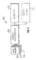
- FIG. 2is a simplified block diagram of the rate sensor, system electronics, and display useful in the practice of the present invention.
- FIG. 3is a more detailed block diagram of one channel of three corresponding to the block diagram of FIG. 2 .
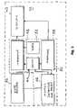
- FIG. 4is a still more detailed block diagram of one channel of the present invention, shown along with additional subsystems of the present invention.
- FIG. 5is a key for FIGS. 6 and 7 .
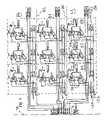
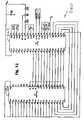
- FIG. 6is a detailed electrical schematic of ROLL, PITCH and YAW sensors and associated integrator and averager circuitry, useful in the practice of the present invention.
- FIG. 7is a detailed electrical schematic of overrange, overrate, and motion detectors and associated circuitry useful in the practice of the present invention.
- FIG. 8is a detailed electrical schematic of the additional subsystems of FIG. 2 .
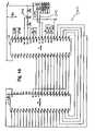
- FIG. 9is a wiring diagram for certain parts of the present invention.
- FIG. 10is a detailed electrical schematic of an analog to digital converter and display for the ROLL channel of the present invention.
- FIG. 11is a detailed electrical schematic of an analog to digital converter and display for the PITCH channel of the present invention.
- FIG. 12is a detailed electrical schematic of an analog to digital converter and display for the YAW channel of the present invention.
- FIG. 13is a simplified block diagram of an alternative embodiment of the present invention.
- FIG. 14is a perspective view of an acetabular alignment instrument for use in obtaining a desired orientation for a prosthetic acetabular socket with respect to a patient's acetabulum, according to one embodiment of the present invention.
- FIG. 15is a plan view of the top or distal face of the alignment guide shown in FIG. 14 .
- FIG. 16Ashows a perspective view of an attachment base for attaching the device to the support shaft 304 , according to one embodiment of the present invention.
- FIG. 16Bshows a schematic view of an alternative attachment base for attaching the device to a surgical instrument or to the patient's body, according to one embodiment of the present invention.
- FIG. 17is a perspective view showing the instrument of FIG. 14 used to identify the plane of the acetabular rim.
- FIG. 18is a perspective view showing the instrument of FIG. 14 used for positioning an acetabular prosthetic socket.
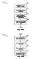
- FIGS. 19A and 19Bare flow charts illustrating operation of an alignment instrument for orientation of an acetabular prosthetic socket.
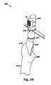
- FIG. 20shows a femoral broaching instrument adapted for aligning the femoral broach with the greater and lesser trochanter of the proximal femur.
- FIGS. 21A and 21Bare top and side plan views of a femoral alignment guide.
- FIGS. 22A and 22Bare a side plan view and a front plan view of an implant instrument and alignment guide for identifying the plane of the glenoid during a TSR procedure.
- FIG. 23is a flowchart describing the use of the alignment guide of FIG. 22 .
- FIG. 24is a perspective view showing a surgical orientation system utilizing dual surgical orientation devices in conjunction with the instrument of FIG. 14 in a THA procedure, according to one embodiment of the present invention.
- FIG. 25is a flowchart describing the use of the surgical orientation system of FIG. 24 to align and place the acetabular prosthetic component in a THA procedure, according to one embodiment of the present invention.
- FIG. 1is a perspective view of a surgical orientation device 10 , according to one embodiment of the present invention.
- the device 10includes a housing 12 , a power switch 14 , displays 18 , a zero button 20 , and indicator lights 22 , 24 , and 26 .
- the housing 12contains the electronic circuitry and components necessary for device operation.
- the housing 12may be made from any material suitable for use within a surgical field or patient treatment setting.
- the device 12may be either disposable or reusable.
- the displays 18include a ROLL display 18 a , a PITCH display 18 b , and a YAW display 18 c . These displays 18 provide an indication of the angular orientation of the device in three dimensions, which allow the device to function as a three-dimensional goniometer.
- the displays 18may be a gauge of any type (e.g., analog meter, digital display, color bar, and thermocouple meter), and may be integrated on the housing or part of a separate, stand-alone device.
- the indicator lightsinclude a wait/ready or RUN indicator 22 , a LOW BATTERY indicator 24 , and an overrange or ERROR indicator 26 .
- the indicator lightse.g., LEDs
- the indicator lightsare integrated on the housing, to indicate when a positional property of interest, such as a angle, has been reached and/or not reached and/or exceeded.
- the device 10further includes attachment straps 28 connected to the housing 12 .
- the straps 28are configured to allow attachment of the device 10 to a surgical instrument, implant, or prosthetic device.
- the straps 28are replaced with clips adapted for coupling with one or more surgical instruments.
- the device 10may be transferable from instrument to instrument within an implant system or systems, or may be dedicated for use with one instrument.
- the device 10may in addition or in the alternative include sensors and displays for providing linear positioning information.
- the device 10may include only one or two of the ROLL, PITCH, and YAW displays 18 and the related circuitry.
- the deviceincludes the sensors, further described below, for providing position and orientation signals.
- the sensorfor example, may be directly integrated into the body of the housing 12 or mounted onto the body of the housing 12 .
- the sensorsmay be adhered to the housing 12 , located inside the housing 12 , or fabricated directly on the surface of the housing 12 , for example, by depositing a layer of silicon on the housing 12 by chemical vapor deposition (CVD) or sputtering, and then building the devices in this silicon layer using techniques common to or derived from the art of semiconductor or MEMS processing.
- CVDchemical vapor deposition
- the device 10is adapted to receive orientation and positioning signals from sensors located in an external device.
- the device 10may have receptacles for attachment to such an external device through direct cable or wireless communication capabilities such as RF and IR.
- such an external deviceis attached to the surgical instrument or prosthetic, and the device 10 is used by the surgeon as an interface.
- the sensoris connected, via wireless and/or wired connections, to a computer or other electronic instrument, which may record or display the sensor measurements (e.g., temperature), and which may at least partially control or evaluate the sensor.
- a computer or other electronic instrumentmay at least partially control the sensor by, for example, performing sensor calibration, performing real-time statistical analysis on the data from the sensor, or running error detection and correction algorithms on the data from the sensor.
- the device 10includes communication capabilities for interacting with other equipment, for example, a computer generated image recreation system. It may, for example, be incorporated for use with computer aided surgical navigation systems, such as VectorVision available from BrainLab, Inc. of Germany, OrthoPilot, available from Aesculap, Inc. of Germany, HipNav, available from Casurgica, Inc., of Pittsburgh, Pa., and Navitrack, available from Orthosoft-Centerpulse Orthopedics, of Austin, Tex.
- data received from a sensormay be used by the computer system to control and/or modify a position of an implant.
- the computer or other electronic instrumentmay be configured to activate the appropriate controls or devices as necessary based on the data received from the sensor.
- Manual adjustmentsmay also be made in response to the data received from the sensor.
- data from the sensorcan be used in a feedback loop with positioning elements (either directly, via a computer or other electronic instrument, or by manual control) to maintain a desired property, such as an orientation or position.
- an operatorUpon attachment of the device 10 to a surgical instrument, an operator, such as a surgeon for example, can use the device 10 to obtain three-dimensional orientation information.
- This combination of the device 10 with a surgical instrumentis useful for assisting surgical procedures wherein one anatomical part is desirably aligned with another anatomical part.
- a limb-to-torso joint replacemente.g., THR or TSR
- an implantsuch as an acetabular cup
- the acetabular cupis desirably aligned with respect to the plane of the acetabulum.
- the present inventionallows a surgeon to establish a reference plane corresponding to the plane of the acetabulum by positioning the device to physically align the device with the plane of the acetabulum and then zeroing the display when the device is aligned with the plane of the acetabulum to establish the reference plane. From then on, the device provides three dimensional angular information (ROLL, PITCH, and YAW) to the surgeon as the device is moved angularly with respect to the reference plane. Additionally, the device 10 of the present invention may be used by a surgeon to identify and measure movement of a patient's body during a surgical procedure such as, for example, a total or partial hip or knee replacement. Monitoring and measuring patient movement during such procedures aids in implanting prosthetic devices in a desired orientation.
- FIGS. 2-13show block diagrams and schematics illustrating the circuitry of the device 10 .
- FIGS. 14-20illustrate alignment guides used for identifying the desired reference plane, along with methods of using the present invention in joint replacement procedures.
- position informationis obtained using an angular measurement and display system 30 , preferably having three RATE SENSOR blocks 32 , 34 , 36 which measure angular rate of change and deliver respectively, ROLL, PITCH, and YAW information to a SYSTEM ELECTRONICS block 38 .
- the SYSTEM ELECTRONICS blockconverts the angular rate of change into angular position information and uses the DISPLAY block 40 to provide ROLL, PITCH, and YAW information in a human readable form, and additionally or alternatively, in electronic form for use by other systems, such as a data logger (not shown).
- An optional block 41is shown in FIG. 2 to illustrate the communication capabilities mentioned above.
- Block 41represents a communication link which may be as simple as a wire, or may include an interface which may be wired or wireless, and may encompass electrical, acoustical (preferably ultrasonic), radio frequency, or optical communication technologies, all of which are considered to be within the term “electronic,” as that term is used herein. It is to be understood that block 41 represents an output with the angular orientation and (optionally) linear position information made available in a machine-readable (e.g., computer-compatible) format, while block 40 has a human readable display of the output information in a visually perceptable format.
- a communication linkwhich may be as simple as a wire, or may include an interface which may be wired or wireless, and may encompass electrical, acoustical (preferably ultrasonic), radio frequency, or optical communication technologies, all of which are considered to be within the term “electronic,” as that term is used herein. It is to be understood that block 41 represents an output with the angular orientation and (optionally) linear position information made available in
- FIG. 3a more detailed block diagram of one channel, e.g., the ROLL channel 42 , may be seen.
- the other two (PITCH and YAW) channelsare preferably identical to the ROLL channel 42 .
- dashed line 38encloses those blocks which form part of the SYSTEM ELECTRONICS 38 for the ROLL channel 42 .
- DISPLAY 40 in FIG. 3refers to the display function for this channel, i.e., it includes a display of ROLL angular information.
- the RATE SENSOR 32is preferably a MEMS (micro-electro-mechanical systems) device that provides angular rate of change information to a SWITCH block 44 and a MOTION DETECTOR AND DELAY block 46 .
- SWITCH block 44receives command information from the MOTION DETECTOR AND DELAY block 46 and directs the rate of change information to either an INTEGRATOR block 48 or an AVERAGER block 50 .
- a ZERO block 52permits resetting the INTEGRATOR 48 to a zero output in a manner to be described.
- FIG. 4a more detailed block diagram 54 shows additional details of one channel (with the ROLL channel 42 used as an example) along with additional supporting functions of the SYSTEM ELECTRONICS 38 .
- Each channelincludes a MOTION DETECTOR block 56 and a MOTION HOLD-ON DELAY block 58 within the MOTION DETECTOR AND DELAY functional block 46 which controls the operation of a relay type switch 60 in SWITCH functional block 44 to switch between INTEGRATE and AVERAGE functions.
- An OVERRANGE DETECTOR block 62monitors whether the output of the INTEGRATOR block 48 reaches an OVERRANGE condition (corresponding to an angular position beyond which the system 30 is able to measure).
- An OVERRATE DETECTOR block 64monitors the output of RATE SENSOR block 32 and provides an ERROR indication if the rate exceeds that which the system 30 is able to measure.
- Each of the blocks 62 and 64are coupled to an ERROR LATCH block 66 which retains the ERROR condition (whether related to range or rate or both) until reset by the ZERO block 52 .
- a STARTUP CONTROL block 70monitors a POWER SUPPLY block 72 and the MOTION HOLD-ON DELAY block 58 and provides a WAIT/READY signal at a RUN indicator 22 .
- a LOW BATTERY DETECTOR block 74is connected to the POWER SUPPLY 72 and controls a LOW BATTERY indicator 24 .
- FIG. 5is a key to the electrical circuit schematics shown in FIGS. 6 and 7 , which are to be understood to be joined at line 78 .
- Dot dash line 80separates the ROLL channel 42 from a PITCH channel 84 .
- Dot dash line 82separates the PITCH channel 84 from a YAW channel 86 . Since the components and interconnections are the same for each of channels 42 , 84 , and 86 , only ROLL channel 42 will be described, it being understood that the same description applies to each of the other channels, as well.
- ROLL sensor 32(and the PITCH and YAW sensors) are each preferably an ADXRS150 150 degree/second angular rate sensor (gyroscope) on a single chip, in a MEMS technology, available from Analog Devices, One Technology Way, P.O. Box 9106, Norwood, Mass. 02062-9106. It is to be understood that the ROLL, PITCH, and YAW sensors are mounted in a conventional orthogonal 3-dimensional (x-y-z) orientation. Each sensor produces an output voltage RATEOUT that is proportional to the angular rate of rotation of that respective sensor. The output voltage is nominally 2.5 volts for zero rotation. The zero rotation output (or NULL) voltage varies from device to device, and with time and with temperature.
- the RATEOUT voltagevaries above and below NULL for positive and negative rotational movement, respectively.
- the RATEOUT scale factoris typically 12.5 millivolts per degree per second with a full scale corresponding to 150 degrees per second.
- the ROLL sensor RATEOUT signalis also identified as a ROLL RATE signal. It is to be understood that each sensor responds in one plane only, and hence three separate sensors are mounted orthogonally to each other to achieve response in all three conventional mutually perpendicular (x, y, and z) axes.
- the RATEOUT signalis connected through SWITCH block 44 to a low pass filter to produce an averaged representation of the RATEOUT voltage. This is the NULL voltage and it adjusts over time to sensor variations.
- the SWITCH blockin response to an INTEGRATE signal [on line 140 ] from block 58 , see FIG. 8 ) the RATEOUT signal is switched from the AVERAGER 50 to the INTEGRATOR 48 .
- the AVERAGER circuit 50then enters a “hold” mode and retains the most recent previous NULL voltage, using that NULL voltage as a reference throughout the duration of the motion.
- the ROLL channel 42 NULL voltageis buffered by an operational amplifier 88 and delivered as a ROLL S/H signal.
- the operational amplifier integrated circuits 88 in the INTEGRATOR and AVERAGER circuits 48 and 50are preferably AD8606 type op amps, available from Analog Devices.
- AVERAGER circuit 50uses a low pass filter made up of a 2 MEG ohm resistor 90 and a 0.47 microfarad capacitor 92 , resulting in a time constant of one second, which has been found to work well. However, it is to be understood that other part values and other time constants may be used, while still remaining within the scope of the present invention.
- the capacitor 92preferably has a low leakage and low dissipation factor.
- Angular positionis the time integral of rotation rate.
- the SWITCH blocktransfers the RATEOUT signal to the INTEGRATOR circuit 48 to compute angular position.
- the output of the ROLL INTEGRATOR 48is available as a ROLL INT signal.
- INTEGRATOR circuit 48uses a 2.7 MEG ohm resistor 94 and a 0.47 microfarad capacitor 96 to perform the integration.
- the reference for the integrationis the no-motion NULL voltage for that channel.
- the capacitor 96preferably has low leakage and a low dissipation factor.
- the integrating resistor 94 in conjunction with capacitor 96provides a full scale range of over +120 degrees.
- the INTEGRATOR 48is reset to zero by discharging the capacitor 96 .
- relay 116is energized by the ZERO signal on terminal 118 (see FIG. 8 ).
- the relay 116discharges capacitor 96 through a 10 ohm resistor 120 to limit the discharge current.
- integrated circuit comparators 98are preferably LM393 type low power, low offset voltage comparators, available from National Semiconductor Corporation, 2900 Semiconductor Drive, P.O. Box 58090, Santa Clara, Calif., 95052-8090. If the sensor 32 is rotated too fast, the sensor output will saturate and the display would be incorrect. Similarly if the sensor is rotated through too great an angle, the integrator will saturate and the display would be incorrect.
- OVERRATE and OVERRANGE detectors 64 and 62are provided to warn the operator in the event of the occurrence of either or both of these errors.
- Each channelhas a window comparator circuit for each of the OVERRANGE and OVERRATE detectors.
- the comparators 98 in the OVERRATE circuit 64provide the OVERRATE signal on a terminal 100
- the comparators 98 in the OVERRANGE circuit 62provide the OVERRANGE signal on a terminal 102 .
- Comparators 98 in circuit 64monitor and compare the ROLL RATEOUT signal to a fixed level, and comparators 98 in circuit 62 compare the output of the ROLL INTEGRATOR circuit 48 to a fixed level. When the RATEOUT signal exceeds a predetermined level, either positive or negative, the window comparator made up of comparators 98 in the OVERRATE circuit 64 determines that the system is in an OVERRATE error condition.
- the thresholdis set to approximately 150 degrees per second by a tap on the voltage divider string 122 .
- the output of the ROLL INTEGRATOR circuit 48is sent to another window comparator made up of integrated circuit comparators 98 in the ROLL portion or channel of OVERRANGE circuit 62 .
- the INTEGRATOR circuit outputexceeds a predetermined threshold
- the ROLL channel portion of circuit 62determines that the system is in an OVERRANGE error condition.
- the thresholdis set at approximately 120 degrees by a tap on the voltage divider string 122 .
- the twelve comparators in circuits 62 and 64have open collector outputs.
- the six OVERRATE outputs(including the ROLL OVERATE output at terminal 100 ) together with the six OVERRANGE outputs (including the ROLL OVERRANGE output at terminal 102 ) are connected together.
- Both terminals 100 and 102are connected to terminal 104 in the ERROR LATCH circuit 66 (see FIG. 8 ) and form the OVER signal.
- the OVER signalgoes LOW whenever any one of the twelve comparators senses an error condition.
- Terminal 104receives the OVER signal as an active LOW signal setting a type 74HC74 D type flip flop 150 , available from Fairchild Semiconductor Corporation, 82 Running Hill Road, South Portland, Me. 04106.
- the flip-flop 150is configured as a SET-RESET memory element.
- the “Q” outputdrives the ERROR indicator 26 , which is preferably a red LED.
- the flip-flop 150is reset by the ZERO signal on terminal 118 .
- Comparators 98 in the MOTION DETECTOR circuit 56compare the output of the ROLL rate sensor 32 to a fixed level and provide a MOTION signal representative of whether the ROLL rate sensor 32 has experienced motion or not. When rotational motion is detected, the RATEOUT signal deviates from the NULL or no-motion voltage. The RATEOUT signal is sent to a “window” comparator made up of comparators 98 in the MOTION DETECTOR circuit 56 . When the RATEOUT signal deviates from the NULL voltage by a predetermined amount or threshold (either positive or negative) the window comparator detects rotational motion. A threshold of one degree per second has been found to be preferable, but it is to be understood to be within the scope of the present invention to use other values, in the alternative.
- a tap on a voltage divider string 122sets the ROLL comparator MOTION thresholds.
- the divider 122is connected between +5A 124 and circuit common 126 , with the center point connected to the NULL voltage (ROLL S/H) line 128 . This provides that the thresholds are referenced to the NULL voltage and compensates for drift and device-to-device variations in the NULL voltage.
- the MOTION signalappears on terminal 106 in MOTION DETECTOR circuit 56 and is connected to corresponding MOTION terminal 106 in the MOTION HOLD-ON DELAY circuit 58 (see FIG. 8 ).
- Each of circuits 56 , 62 , and 64are provided with a pair of comparators 98 in the ROLL channel 42 so as to provide a bipolar (+/ ⁇ ) comparator function.
- All six MOTION comparators(including ROLL channel comparators 98 ) in channels 42 , 84 and 86 have open collector outputs which are connected together via MOTION terminal or line 106 . It is to be understood that the signal on MOTION line 106 will go to a LOW state whenever any one of the six comparators senses motion.
- a 1 microfarad capacitor 130will discharge through a 14.8K ohm resistor 132 causing a comparator 134 to deliver a HIGH output on line 136 .
- Thisturns on an IRFD 110 type FET transistor 138 which pulls the INTEGRATE line 140 LOW.
- the IRFD 110 type FET transistoris available from International Rectifier at 233 Kansas St. El Segundo, Calif. 90245 USA
- Comparator 134is preferably a type LM393.
- the relay 60 in SWITCH block 44transfers the system from “average” mode to “integrate” mode.
- a pair of 143 K ohm resistors 142 and 144set the threshold voltage for comparator 134 and a 100 K ohm resistor 146 provides hysteresis.
- the RATEOUT signalreturns to the NULL voltage.
- the window comparatorsreturn to the open-collector state, allowing the capacitor 130 to slowly charge through a 1 MEG ohm resistor 148 .
- the system 30remains in the “integrate” mode until capacitor 130 charges sufficiently to switch comparator 134 , which is approximately 0.7 seconds. This allows the system 30 to register any small movements the operator may make at the end of a gross movement. Such small movements may not otherwise be enough to activate the MOTION DETECTOR circuit 56 .
- comparator 134switches and the INTEGRATE line goes HIGH, terminating the “integrate” mode.
- the relay 60releases and the mechanical shock of the release is sensed by at least one of the sensors causing a noise output on one or more RATEOUT lines.
- This noise outputcan be large enough to retrigger the MOTION DETECTOR circuit 56 , resulting in continuous cycling of relay 60 .
- Such undesirable cyclingis prevented by resistor 132 delaying discharge of capacitor 130 until the transient noise caused by the relay release has passed.
- relay 60may be shock mounted.
- the STARTUP CONTROL circuit 70has four functions. It generates a master reset pulse to initialize the system at power on. It provides a three minute warm-up period for the sensors. It enforces the requirement that the sensors not be moving for 10 seconds at the end of the warm-up period (to set the “no-motion” reference). It also gives the user feedback about the system status via the WAIT/READY status of the RUN indicator 22 .
- An LM 393 type comparator 172generates a master reset pulse.
- the pulseis active LOW, with a pulse width of approximately 0.6 seconds, determined by a 1 microfarad capacitor 174 and a 475K ohm resistor 176 .
- the pulse widthis selected to be long enough to fully discharge a 10 microfarad capacitor 178 (through a diode 180 and a 1K ohm resistor 182 ) and at least partially discharge a 390 microfarad capacitor 184 (through a diode 186 and a 1K ohm resistor 188 ).
- the discharge of capacitors 178 and 184is necessary to handle the situation where the system 30 is turned OFF and then immediately turned ON again.
- a 1N5817 type diode 190protects comparator 172 and quickly discharges capacitor 174 on power down.
- a 15.0K ohm resistor 192 and a 34.8K ohm resistor 194provide the reference voltage for comparator 172 , and a 475K ohm resistor 196 provides hysteresis.
- the master reset pulsealso clears a WAIT/READY flip flop 198 , which is preferably a 74HC74 type D flip flop.
- Flip flop 198is cleared during the warm-up or WAIT period and is SET when the system 30 enters the READY state.
- Flip flop 198drives the RUN indicator 22 , which is preferably a yellow/green two color LED driven differentially by the Q and Q-not outputs at pins 5 and 6 of the device 198 .
- Indicator 22is preferably illuminated YELLOW during the WAIT or warm-up period, and switches to a GREEN illumination when the system enters the READY mode.
- a 392 ohm resistor 200provides current limiting for the RUN indicator 22 .
- a 10K ohm resistor 202 connected to the Q output (pin 5 ) of flip flop 198provides an input to the FET transistor 138 which serves as a relay driver for relay 60 .
- the input provided through resistor 202forces the system to the AVERAGE mode by connecting the sensors to the AVERAGER amplifiers, since the Q output remains LOW during the warm-up period.
- An LM 393 comparator 204is the warm-up timer.
- a 221 K ohm resistor 206 and capacitor 184set the duration of the warm-up period.
- the output (at pin 7 ) of comparator 204goes to an open collector condition. This clocks the WAIT/READY flip flop 198 into the READY state, provided that 10 seconds have elapsed with no motion at the end of the warm-up period.
- the 10 second “no-motion” requirementis enforced by a 10 second timer, which uses an LM 393 type comparator 208 .
- the 10 second timermonitors the MOTION signal on line 106 (buffered through another LM 393 type comparator 210 ). If any of the sensors detect motion, capacitor 178 will be held discharged by comparator 210 acting through a diode 212 and a 475 ohm resistor 214 . When none of the sensors detect motion, capacitor 178 will begin to charge through a 1.00 MEG ohm resistor 216 .
- the POWER SUPPLY circuit 72utilizes two integrated circuit voltage regulators 110 preferably LM2931 type, available from National Semiconductor Corporation. Regulators 110 and 112 each provide regulated +5 volts DC power to the various circuits shown. Regulator 110 provides power to digital circuits in system 30 (indicated by “+5D”) and regulator 112 provides power to the analog circuits (particularly amplifiers 88 , as indicated by “+5A).
- the sensors, (including ROLL sensor 32 )require both analog and digital power.
- a 9 volt battery 272provides power to the regulators 110 , 112 and also to various other components and subcircuits, such as comparators 98 and A/D converter 114 (shown in FIG. 10 ).
- a diode 152protects against reverse battery polarity.
- An LM393 type comparator 154is used for the LOW BATTERY DETECTOR 74 .
- comparator 154switches, driving the signal on the BATLOW 2 terminal 156 LOW, turning on the BATTERY LOW indicator 24 , which is preferably a red LED.
- the LEDis supplied through a 392 ohm resistor 158 .
- a precision voltage reference diode 160sets a reference voltage at the “ ⁇ ” input (pin 2 ) of comparator 154 to 1.2 volts.
- a 100K ohm resistor 162 and a 21.5K ohm resistor 164set the voltage at the “+” input (pin 3 ) of comparator 154 to 1.2 volts when the battery voltage is 6.8 volts.
- a 10 microfarad capacitor 166delays the rise of the reference voltage at pin 2 of comparator 154 to force the comparator output voltage at the BATLOW 2 terminal 156 HIGH at power on.
- a diode 168 and a 57.6K ohm resistor 170provide hysteresis to lock the output 156 in a LOW state once a low battery condition is detected. This prevents the BATTERY LOW indicator 24 from cycling ON and OFF in response to changing current demands on the battery 272 , causing the battery voltage to fluctuate above and below 6.8 volts.
- FIG. 8also includes the details of the ZERO block or circuit 52 .
- a CD4093 type NAND Schmitt Trigger integrated circuithas a NAND gate 218 driving an IRFD 110 type FET transistor 220 which energizes relay 116 for the ZERO function (see FIG. 6 ).
- One input (at pin 9 ) of NAND gate 218is connected to the Q output (at pin 5 ) of the WAIT/READY flip flop 198 . This holds the system 30 in the ZERO state or condition during the warm-up period.
- the ZERO conditionis cleared and the INTEGRATOR circuit 48 is enabled. Manual ZERO is accomplished by closing a ZERO switch 224 (see FIG.
- NAND gates 232 and 234(also type CD4093) form a square wave oscillator with a period of about 50 milliseconds.
- the oscillatoris enabled by comparator 134 releasing the input at pin 1 of gate 232 to go HIGH.
- the oscillator output(at pin 4 of gate 234 ) drives an IRFD 110 type FET transistor 236 .
- transistor 236When transistor 236 is ON, it increases the current in the RUN indicator LED 22 by providing a path to circuit common through a 392 ohm resistor 238 .
- the transistor 236is turned ON and OFF every 50 milliseconds while the system senses motion, providing a visually perceptible feedback or indication to the user that the system 30 is sensing motion.
- FIG. 9a wiring diagram for connection of various parts to the STARTUP CONTROL 70 and ZERO block 52 of system 30 may be seen. It is to be understood that the the connections shown correspond to the lowermost connections on the right hand side of FIG. 8 .
- a power switch 14may be used to provide ON-OFF control of the system 30 .
- Battery 272is preferably a 9 volt battery.
- the ZERO switch 224is preferably a normally OFF, momentary ON, spring return pushbutton type switch.
- the output of the ROLL INTEGRATOR block and circuit 48is provided on a ROLL INT terminal or line 242 .
- the output of the ROLL AVERAGER block and circuit 50is provided on a ROLL S/H terminal or line 244 .
- the ROLL INT and ROLL S/H signalsare provided to the analog to digital converter integrated circuit 114 which is preferably a TC7106 type 31 ⁇ 2 digit A/D converter, available from Microchip Technology, Inc., 2355 West Chandler Blvd., Chandler, Ariz. 85224-6199.
- the A/D converter 114contains all the circuitry necessary for analog to digital conversion and also provides decoded outputs for a 31 ⁇ 2 digit LCD display.
- the ROLL S/H signalis provided to the ( ⁇ ) analog input and the ROLL INT signal is provided to the (+) input of the A/D converter 114 .
- the A/D inputsare thus seen to be connected differentially between the NULL reference voltage and the INTEGRATOR output.
- the A/D converteris preferably scaled to display the output in mechanical degrees of rotation.
- the least significant digit outputprovides tenths of degrees and is not used.
- the three most significant digit outputsprovide “degrees, tens of degrees, and 100 degrees” respectively.
- the digital decoded outputs from the A/D converterare connected to a visually perceptible digital display 18 a , preferably a S401C39TR type LCD display available from Lumex, Inc. of 290 East Helen Road, Palatine, Ill. 60067.
- the digital display 18 asimultaneously displays degrees, tens of degrees, 100 degrees, and either a positive or negative sign to indicate direction of rotation from the ZERO condition or position.
- a 10K ohm potentiometer 248provides a single system calibration adjustment for the ROLL channel 42 .
- the PITCH and YAW portions 250 and 260 the DISPLAY block 40are essentially identical to the ROLL portion 240 , each with their own A/D converters 252 and 262 and LCD displays 18 b and 18 c , respectively. It is to be understood that DISPLAY block 40 include the ROLL, PITCH, and YAW displays 18 a , 18 b , and 18 c , and in this embodiment also includes A/D converters 114 , 252 , and 262 .
- the ROLL, PITCH, and YAW datamay be delivered to other circuitry and systems (not shown) in addition to (or as an alternative to) the DISPLAY block 40 .
- the digital data representing the final ROLL, PITCH, and YAW angle selected with respect to the reference planemay be recorded by a data logger (not shown) if desired.
- datamay be provided in serial form as well as in parallel form, using conventional circuitry to produce serial digital data from either the analog values or parallel digital values.
- rate sensor 32has an output that is immediately converted to digital form by an A/D converter 282 (which may be the same or different than A/D converter 114 .
- the A/D converter outputis then provided to a microprocessor-based system 284 which delivers the ROLL, PITCH and YAW information to a DISPLAY 286 which may be the same or different than display 40 .
- This embodimentmay also provide the ROLL, PITCH and YAW information to other circuitry or systems (not shown).
- the device 10can be utilized independently or in conjunction with gyroscopes or other sensors to provide three dimensional positional orientation with or without angular change for applications such as osteotomies, placing screws in the pedicle, bone cuts/preparation during total joint arthroplasties, disc replacement, and position of tunnels for ligament and tendon repairs.
- One sensor useful as an accelerometeris an Analog Devices type ADXL103 accelerometer, which may be used in place of device 32 to detect linear acceleration which is then integrated to obtain linear position (which may be replicated in three orthogonal channels along x, y and z axes).
- ADXL103 type devicesit is believed preferable to include the motion sensing and averaging aspects shown and described herein, to remove device-to-device errors, as is done with the gyroscopic type rate sensors. It is to be understood that if an accelerometer is used to obtain linear position information, two integrations (from acceleration to velocity to position) are needed.
- the device 10further includes additional sensors such as temperature, ultrasonic, and pressure sensors, for measuring properties of biological tissue and other materials used in the practice of medicine or surgery, including determining the hardness, rigidity, and/or density of materials, and/or determining the flow and/or viscosity of substances in the materials, and/or determining the temperature of tissues or substances within materials.
- additional sensorscan, for example, identify the margins between cortical and cancellous bone, determine the thickness of cancellous bone, monitor temperature of cement for fixating implants, and differentiate between nucleus pulposis and annulus of a spinal disc.
- these sensorscan identify cracks/fractures in bone during placement of implants such as pedicle screw placement, screw fixation in bone, femoral implant during THA, and identify tissue-nerve margins to determine proximity of nerves.
- FIG. 14shows an acetabular alignment instrument 300 for use in obtaining a desired orientation for a prosthetic acetabular socket with respect to a patient's acetabulum, according to one embodiment of the present invention.
- the use of such an instrument for orthopaedic hip procedures, such as THR,is well known in the art.
- One such instrument, for example,is disclosed in U.S. Pat. No. 6,743,235, which is hereby incorporated by reference.
- the instrument 300can be any instrument known for the placement and orientation of acetabular components, including the preparation instruments for THR procedures.
- the instrument 300includes a handle 302 , a prosthetic support shaft 304 , an orientation shaft 306 , the surgical orientation device 10 , and an anatomic benchmark alignment guide 308 .
- the surgical orientation device 10is securely attached to the support shaft 304 , such that the device 10 moves in concert with the support shaft 304 .
- the orientation shaft 306includes an orientation guide 310 , which may be used by a surgeon for manually orienting an implant or prosthetic.
- the instrument 300does not include an orientation guide 310 .
- the support shaft 304has external threads 314 at a distal end. The threads 314 are adapted to mate with corresponding internal threads 316 on the alignment guide 308 , such that the alignment guide is releasably attachable to the support shaft 304 .
- FIG. 15is a plan view of the top or distal face of the alignment guide 308 .
- the alignment guide 308includes a body portion 318 and wings or arms 320 a , 320 b , and 320 c , which are disposed generally in the same plane.
- the body portion 318includes internal threads 316 for mating with the support shaft 304 .
- the arms 320secured at points 320 degrees apart around the circumference of the body portion 318 by pivots 324 a , 324 b , and 324 c .
- the pivots 324allow for slight in-plane rotation of the arms 320 where necessary, for example to avoid contact with an anatomical aberration as the lip of the acetabulum.
- the arms 320are fixed to the body portion 318 such that they cannot pivot.
- the pivots 324are located at any point along the arms 320 .
- the arms 320include an inner arm 326 and an outer arm 328 , which are coupled to each other such that the outer arms 328 can telescope or extend with respect to the inner arms 326 .
- This telescoping actionallows the surgeon to adjust the length of the arms 320 , based on the diameter of a particular patient's acetabulum.
- the arms 320are made from a unitary piece and thus are not amenable to a length adjustment.
- the distal ends of the arms 320define an outer diameter of the alignment guide 308 .
- the arms 320in one embodiment, have a length of from about 40 to about 70 mm, with each arm 320 having the same length.
- the length of the armsis driven by the diameter of a particular patient's acetabulum, such that the outer diameter of the alignment guide is slightly larger (e.g., 1-3 mm) than the diameter of the acetabulum.
- the arms 320have a length of 48, 52, 56, 60, or 64 mm.
- the arms 320have a width of from about 2 to about 5 mm and a thickness of from about 1 to about 3 mm. In one exemplary embodiment, the arms have a width of about 3.5 mm and a thickness of about 2 mm.
- FIG. 16Ashows a perspective view of an attachment base 332 for attaching the device 10 to the support shaft 304 .
- the attachment base 332includes a body 334 and a brace 336 .
- the body 332is dimensioned to generally mate with the dimensions of the housing 12 of the device 10 .
- the body 334includes mounting tabs 338 for mating with the housing 12 and fixing the position of the device 10 with respect to the attachment base 332 .
- the body 334includes a groove 339 shaped to mate with the outer surface of the support shaft 304 . This configuration increases the surface contact between the attachment bases 332 and the support shaft 304 , which enhances fixation of the two components.
- the body 334includes holes 340 for accepting a fastener, such as string, wire, spring wire, a strap, a hook and loop fastener, or any other fastener.
- the fasteneris used to fix the body 334 to the support shaft 304 .
- the brace 336includes a curve 342 configured to accept the outer surface of the orientation shaft 306 .
- the attachment base 332is attached to the instrument 300 by placing the body 334 on the support shaft 304 and the curve 342 of the brace 336 against the orientation shaft 306 . In this position, the brace 336 resists rotation of the attachment base 332 around the circumference of the support shaft 304 .
- FIG. 16Bdepicts an alternative attachment base 342 employing a tapered tab 344 sized and shaped to mate with a corresponding female recess (not shown) in the device 10 .
- FIG. 17shows the instrument 300 during use.
- the instrument 300is in contact with a portion of the pelvic bone 350 .
- the alignment guide 308is contacting the acetabular rim 352 of the acetabulum 354 .
- the arms 320have a length sufficient to reach the acetabular rim 352 .
- the support shaft 304is also adapted to mate with a ball support 360 , which is used to support an acetabular prosthetic socket 362 .
- FIG. 19is a flowchart illustrating an acetabular alignment process 370 for using the alignment instrument 300 to orient an acetabular prosthetic socket 362 .
- the process 370includes powering on the device using the power switch 14 and attaching the device to the shaft of the alignment instrument 300 (block 372 ).
- the alignment guide 308having the appropriate diameter, is then attached to the end of the support shaft 304 (block 374 ).
- the instrument 300is placed into the surgical site, such that the alignment guide 308 is resting on the rim 352 of the acetabulum 354 (block 376 ).
- the center of the alignment guide 308is generally aligned with the center of the acetabulum 354 and the arms are place on the rim 352 of the acetabulum 354 , as follows. A first arm is placed on the most superior point of the acetabulum, a second arm is positioned at the lowest point of the acetabular sulcus of the ischium, and a third arm is positioned at the saddle point at the confluence between the illiopubic eminence and the superior pubic ramus. In the absence of a significant acetabular rim, the above anatomic landmarks may be used to identify the plane of the acetabulum.
- the arms 320are adjusted in length by the surgeon using a telescoping action.
- the surgeonmay need to pivot the arms 320 to avoid an osteophyte or other surface aberration on the rim 352 of the acetabulum 354 .
- the surgeonremoves the instrument 300 from the surgical patient's body.
- the alignment guideis then removed and the ball support 360 and prosthetic socket 362 are attached to the support shaft 304 (block 380 ).
- the surgeonplaces the prosthetic socket 362 into the acetabulum 354 using the instrument 300 (block 382 ).
- the surgeonmanipulates the orientation of the prosthetic socket 362 in the acetabulum 354 using the instrument 300 , until the device 10 indicates the desired orientation (block 384 ).
- the surgeonmanipulates the instrument 300 until the displays 18 on the device indicate an anteversion of 25 degrees.
- the ROLL display 18 aindicates “25” and the PITCH display 18 b and YAW display 18 c indicate zero.
- the prosthetic socket 362is secured to the acetabulum 354 (block 386 ).
- the device 10is used on other acetabular instruments to identify the orientation of the instrument with respect to a previously set plane of the acetabulum.
- the information provided by the devicemay, for example, be in the form of angular measurements to identify information such as rotation, abduction and version angles.
- the device 10also provides information on position changes in linear dimensions to identify properties such as depth of insertion and changes in center of rotation.
- the instrument 300including the device 10 is capable of sub-millimeter and sub-degree accuracy to monitor the position and angle with reference to the pelvis. It can provide continuous measurements of cup abduction and flexion angles. These angles may be provided during placement of the preparation instruments, the insertion of the implant, after it is placed and, if needed, after placement of supplementary screws.
- FIG. 20shows a femoral implant instrument 400 for aligning the femoral implant with the greater and lesser trochanter of the proximal femur.
- the instrument 400may be, for example, a femoral implant insertion instrument, a femoral rasp, or a femoral broaching instrument.
- the instrument 400includes a handle 404 , a rasp or broach 408 , a femoral alignment guide 430 , and the device 10 .
- the instrument 400is used to clear and shape the cancellous bone surrounding the canal of the proximal femur 414 .
- the broach 408is releasably coupled to the handle 404 , such that the surgeon can readily change the broach 408 to one of a different size.
- the broach 408is shown in FIG. 20 with the cutting segment embedded in the femur 414 .
- the instrument 400is a femoral broaching instrument such as Broach Handle #4700-RH02, available from Wright Medical Technology, Inc. of Arlington, Tenn.
- the broach 408is any other rasp or broach known in the art.
- the guide 430is placed on the body 404 at the desired reference point and attached using the locking mechanism 432 . As further explained below, the surgeon may use the guide 430 by aligning it with the greater trochanter 418 and the lesser trochanter 422 at a proximal end of the femur 414 .
- FIGS. 21A and 21Bare top and side plan views of a femoral alignment guide 430 .
- the guide 430includes a mounting ring 432 , a lesser trochanter alignment arm 434 , and a greater trochanter alignment arm 436 .
- the alignment arms 434 and 436extend in generally opposing directions from the mounting ring 432 .
- the alignment arms 434 and 436include angles ends 438 and 440 , respectively.
- the angled ends 438 and 440are usable by the surgeon to align the guide 430 with respect to the patient's anatomy.
- the mounting ring 432includes a locking screw 442 for securing the guide 430 to the instrument 400 .
- the greater trochanter alignment arm 436has a length (l 2 ) of about 40 percent of a length of the lesser trochanter alignment arm 434 .
- the lesser trochanter alignment arm 434has a length (l 1 ) of between about 85 and about 105 mm.
- the alignment arm 434has a length (l 1 ) of about 95 mm.
- the mounting ring 432has an internal diameter ( ⁇ ) of between about 35 and 45 mm. The specific dimensions of the alignment guide will depend upon the size of the handle 404 and the patient's proximal femur 414 .
- the femoral alignment guide 430is used to align the femoral implant by referencing the lesser and greater trochanter of the proximal end of the femur.
- the guide 430can also be used to mark the lesser or greater trochanter, or any other point marked by the surgeon, to fix the predetermined/measured angle of the preparation instruments or implant. The surgeon may then move the femur without disrupting his measurement of the chosen anteversion.
- the guide 430is attached to a femoral broaching instrument.
- the guide 430is placed at the desired angle and the device 20 is set to zero.
- the guide 430in one embodiment, is generally aligned with a center of the greater trochanter 418 and the lesser trochanter 422 .
- the present inventionis also useful in assisting a surgeon with a TSR procedure.
- one of the stepsis placing a glenoid implant into the glenoid of the patient's scapula.
- One such glenoid implantis described in U.S. Pat. No. 6,679,916, which is hereby incorporated by reference.
- Another step of the TSR procedureis placement of the humeral implant.
- the device 10 of the present inventionis useful for assisting a surgeon in achieving proper orientation of the glenoid implant with respect to the glenoid vault and for achieving proper orientation of the humeral implant.
- the device 10for example, can be attached to a T-handle or a drill commonly used by the surgeon with the glenoid planer.
- the device 10in further embodiment, can be attached to a tapered reamer used for reaming the humeral canal or to a humeral head cutting guide.
- FIG. 22Ashows a side plan view of a glenoid implant insertion instrument 500 for use in orientation of a glenoid implant.
- the insertion instrument 500includes a shaft 504 and an alignment guide 510 .
- FIG. 22Bshows a front plan view of the alignment guide 510 .
- the alignment guide 510includes an upper arm 512 , a lower arm 514 , an anterior arm 516 , and a posterior arm 518 , which are attached to a hub 520 .
- the armsare sized such that they span the glenoid rim for a particular patient.
- FIG. 23is a flowchart illustrating a glenoid implant alignment process 550 for using the implant insertion instrument 500 to orient a glenoid implant.
- the process 550includes securely attaching the device 10 to the shaft of an implant insertion instrument 500 or glenoid planing instrument (block 554 ).
- the alignment guide 510is attached to the end of the instrument where the glenoid implant is normally attached (block 556 ).
- the guide 510is placed on the rim of the glenoid, such that the upper arm is placed at the most superior position of the rim, and the anterior and posterior arms are generally aligned in the center of the superior/posterior glenoid (block 558 ). Again, the arms may be adjusted to avoid significant osteophytes.
- the “zero” switchis then depressed to set the displays 18 on the device 10 to zero, which sets the reference plane (block 560 ).
- the alignment guide 510is removed and the glenoid implant is attached to the insertion instrument 500 (block 562 ).
- the surgeonuses the displays 18 on the device 10 to achieve desired orientation and/or positioning of the glenoid implant (block 564 ). The surgeon then fixes the glenoid implant in the desired location.
- the device 10is used by a surgeon to facilitate TKA.
- the device 10may be affixed to the initial guides commonly used by surgeons, to enable more accurate alignment than that provided by the existing guides.
- the device 10can be affixed to the cutting blocks to provide more accurate rotational alignment, varus/valgus alignment, and level of resection.
- the device 10can also be affixed to any other instruments known in the art and commonly employed in a TKA procedure.
- one device 10is coupled to a surgical instrument and a second device 10 or other navigation aid or device is attached to a selected location on a patient's body to form a surgical navigation system.
- the device 10 attached to the patient's bodyoperates to track and display patient movement, if any, during the surgical procedure to improve the accuracy and reproducibility of the alignment and placement of the prosthetic device. If there is movement of the patient such that the benchmark position and thus the orientation of the prosthetic implant would be inaccurate if based solely on the navigation device 10 attached to the surgical implant instrument, the navigation device attached to the patient's body will track this movement and the surgeon can adjust his target orientation appropriately.
- the navigation device attached to the surgical instrumentafter being zeroed, operates to register any changes to the position of the prosthetic implant, such as rotation, abduction and anteversion, relative to a benchmark, or reference, acetabular plane in space.
- the navigation device 10 attached to the patient's bodye.g., on the pelvic bone, will, after being zeroed in the same, or substantially the same, position and orientation as the device 10 attached to the surgical instrument, track any movement of the patient's body, and hence, the patient's actual acetabular plane, relative to the reference acetabular plane.
- the two navigation devicesmay, in one embodiment, be operatively connected via a communication channel, which may be wired (e.g., a cable), or wireless (e.g., radio-frequency or infrared). In one embodiment, the two navigation devices are not so connected. In still other embodiments, one or both of the navigation devices may be operatively connected to an external computer or other electronic equipment such as, for example, a computer-aided surgical navigation system as described above.
- a communication channelwhich may be wired (e.g., a cable), or wireless (e.g., radio-frequency or infrared). In one embodiment, the two navigation devices are not so connected. In still other embodiments, one or both of the navigation devices may be operatively connected to an external computer or other electronic equipment such as, for example, a computer-aided surgical navigation system as described above.
- the terms “reference acetabular plane” and “reference plane of the acetabulum”refer to the plane in space defined by the patient's acetabular rim at the time the two devices of the navigation system are zeroed. The location and position of the “reference plane of the acetabulum” is fixed at the time the navigation devices are zeroed, and remains constant throughout the surgical procedure.
- the term “position”may refer to linear position, angular orientation, or both.
- FIG. 24depicts a dual-device surgical navigation system 600 in use in conjunction with the acetabular alignment instrument 300 as described above, in a THR procedure.
- the system 600includes an instrument orientation device 10 a , a body orientation device 10 b , an acetabular alignment instrument 300 as described above, a pelvic docking mechanism 610 , and a communication channel 620 .
- the instrument orientation device 10 ais located on the support shaft 304 of the instrument 300 , and is attached thereto according to attachment configurations and methods described above.
- the body orientation device 10 bis adapted to mate with the pelvic docking mechanism 610 . Either or both of the orientation devices 10 a and 10 b may be devices 10 as described above, with substantially the same functionality. Alternatively, the system 600 may employ other orientation devices or navigation guides.
- the docking mechanism 610is generally of a size and shape to mate with the body orientation device 10 b , and may be similar to the attachment base 332 shown in FIGS. 16A and 16B .
- the pelvic docking mechanism 610may be temporarily attached to the pelvic bone 350 using pins, threaded pins or screws, or adhesive as is known in the art.
- the pelvic docking mechanism 610is coupled to the patient externally, such as to the skin, in the pelvic region.
- the pelvic docking mechanism 610is omitted, and the body orientation device 10 b may be coupled directly to the pelvic bone 350 using pins, screws, etc.
- the communication channel 620may be a cable.
- the communication channel 620may be any wireless communication path utilizing infrared or radio-frequency telemetry, as are well known in the art.
- the communication channel 620operates to permit data transfer between the devices 10 a and 10 b during use.
- the two navigation devices 10 a and 10 bare not required to be of the same type or have the same functionality.
- the instrument orientation device 10 aincludes a processor for performing data processing necessary to automatically adjust the orientation of the instrument 300 to compensate for movement, if any, of the patient as detected and measured by the body orientation device 10 b .
- the body orientation device 10 bmay include a light or audible tone to indicate when patient movement may have occurred.
- the body orientation device 10 bneed not include a display.
- the body orientation device 10 bmay include only a sensor array package, which may include minimal electronics (e.g., circuitry to reset or zero the sensor output, transmitters) and the means (e.g., data port, RF or IR transceiver) to be operatively coupled to another device.
- the instrument orientation device 10 amay include a peripheral sensor array attached to the patient's body. This sensor array is capable of transmitting (via wired or wireless communication channel) positional information to the device 10 a for automatic adjustment of the device display in the event of patient movement.
- the body orientation device 10 bmeasures patient movement, if any, during the surgical procedure. If such patient movement occurs, the readings on the device 10 a are adjusted, such that the surgeon may orient the instrument 300 to achieve the desired orientation of the prosthesis to the patient's selected anatomical location. In one embodiment, this adjustment is accomplished automatically within the instrument orientation device 10 a based on angular, and in some embodiments, linear displacement information transmitted by the body orientation device 10 b via the communication channel 620 . In another embodiment, the adjustment is done manually by the surgeon by comparing the displays 18 of the two devices 10 a and 10 b . In yet another embodiment, the surgical personnel may use the body orientation device 10 b to maintain the patient in a desired position, and to adjust the patient's position as needed to re-establish the desired patient position if movement does occur.
- FIG. 25is a flowchart illustrating an acetabular alignment process 650 for using the instrument 300 in conjunction with the dual-device orientation system 600 to orient an acetabular prosthetic socket 362 according to one embodiment of the present invention.
- the process 650includes, in one embodiment, attaching the pelvic docking mechanism 610 to the pelvic bone 350 at a predetermined location (block 654 ), powering on the devices 10 a and 10 b , attaching the attachment base 332 to the instrument 300 , temporarily attaching the body orientation device 10 b to the attachment base 332 (block 658 ), and attaching the alignment guide 308 to the end of the support shaft 304 of the instrument 300 , and.
- the surgeonplaces the alignment guide 308 on the rim 352 of the acetabulum (block 662 ) as described above.
- the surgeondepresses the zero button 20 of the body orientation device 10 b (block 666 ) and then, with the patient completely immobilized and while holding the instrument 300 in the same position, the surgeon removes the body orientation device 10 b from the instrument 300 and attaches the body orientation device 10 b to the pelvic docking mechanism 610 (block 670 ). Then, while continuing to immobilize the patient and continuing to hold the instrument 300 in the same position, the surgeon attaches the instrument orientation device 10 a to the instrument 300 and depresses the zero button 20 of the instrument orientation device 10 a (block 674 ).
- both orientation devices 10 a and 10 bare zeroed in the same position relative to the reference plane of the acetabulum. Accordingly, each of the devices 10 a and 10 b +will subsequently measure any angular displacement it experiences relative to that reference acetabular plane.
- the surgeonafter attaching the pelvic docking mechanism 610 to the pelvic bone 350 at a predetermined location, powering on the devices 10 a and 10 b , attaching the attachment base 332 to the instrument 300 , attaching the alignment guide 308 to the end of the support shaft 304 of the instrument 300 , the surgeon then attaches the instrument orientation device 10 a to the instrument 300 . Then, after correctly positioning the alignment guide 308 on the rim 352 of the acetabulum, the surgeon places the body orientation device 10 b adjacent to the instrument orientation device 10 a and aligns the two devices 10 a and 10 b to the same orientation. The surgeon then zeroes both devices 10 at substantially the same time by depressing the zero button on each device.
- the system 600may be configured to zero both devices by depressing the zero button on only one.
- the devices 10may be configured such that when the surgeon depresses the zero button on the instrument orientation device 10 a , a reset command is sent, via the communication channel 620 , to the body orientation device 10 b , simultaneously zeroing the latter device.
- the surgeonthen attaches the body orientation device 10 b to the pelvic docking mechanism 610 .
- the position of the body orientation device 10 b relative to the reference plane of the acetabulumwill be slightly offset linearly from the position of the instrument orientation device 10 a relative to the reference plane of the acetabulum, because the body orientation device 10 b and instrument orientation device 10 a occupy different locations in space when they are zeroed.
- this difference in the device positions relative to the reference plane of the acetabulumdoes not significantly affect the performance of the orientation system 600 .
- an internal processor in the instrument orientation device 10 a and/or the body orientation device 10 bmay be programmed to compensate for this offset.
- the position of the body orientation device 10 b on the pelvic bone 350establishes an intermediate position for this device relative to the reference plane of the acetabulum.
- the displays 18if present, on the body orientation device 10 b may indicate the angular displacement the body orientation device 10 b experienced in being moved from its zero position to its intermediate position on the patient's pelvic bone 350 .
- the body orientation device 10 bmay include internal electronics and/or circuitry whereby its displays 18 may be reset to “0, 0, 0” by the surgeon after the device 10 b is attached to the pelvic bone 350 , while the device's motion sensors continue to measure movement relative to the device's original zero position.
- This embodimentthus provides a direct indication on the displays 18 of the body orientation device 10 b of any patient movement after the device 10 b is placed on the pelvic bone 350 .
- the surgeonthen removes the instrument 300 from the surgical patient's body.
- the alignment guideis then removed and the ball support 360 and prosthetic socket 362 are attached to the support shaft 304 (block 678 ).
- the surgeonthen places the prosthetic socket 362 into the acetabulum 354 using the instrument 300 (block 682 ).
- the surgeonthen manipulates the orientation of the prosthetic socket 362 in the acetabulum 354 using the instrument 300 , until the instrument orientation device 10 a indicates the desired orientation. Any movement of the patient registered by the body orientation device 10 b is used to adjust the target position of the instrument 300 and, in turn, the prosthetic socket 362 (blocks 686 - 694 ).
- the surgeonmay desire to implant the prosthetic socket with an anteversion of 25 degrees relative to the reference plane of the acetabulum. If the patient's body has moved since the devices 10 a and 10 b were zeroed and the body orientation device 10 b was coupled to the pelvic docking mechanism 610 , this movement must be taken into account when orienting the instrument 300 to the acetabulum. For example, if the body has rolled 2 degrees, pitched 2 degrees and yawed 1 degree since the devices 10 a and 10 b were zeroed and the body orientation device 10 b was attached to the pelvic bone 350 , the orientation of the instrument 300 must be adjusted accordingly to achieve the desired 25 degree anteversion.
- this adjustmentis done manually by the surgeon by comparing the displays 18 of the two devices 10 a and 10 b . If the displays 18 of the body orientation device 10 b were reset to zero after the device was attached to the pelvic bone 350 , these displays 18 will read “2, 2, 1” after the patient has moved as described in the above example. Alternatively, if the displays 18 of the body orientation device 10 b were not reset to zero after the device was attached to the pelvic bone 350 , these displays will read “5, 7, 8” after the patient has moved (a change of 2 degrees ROLL, 2 degrees PITCH, and 1 degree YAW from the device's intermediate position). In both cases, the displays 18 on the instrument orientation device 10 a will still read “0, 0, 0.” To achieve an anteversion of 25 degrees, the surgeon will then manipulate the instrument 300 until the displays 18 on the instrument orientation device 10 a read “27, 2, 1.”
- the positional correction of the instrumentmay be accomplished automatically by an internal processor, controller, or discrete circuitry components within the instrument orientation device 10 a .
- This processor, controller, etc.is adapted to receive as inputs values reflecting positional changes measured by the instrument orientation device 10 a and the body orientation device 10 b , to perform arithmetic calculations on these values, and to generate an output representing the orientation of the instrument orientation device 10 a relative to the body orientation 10 b .
- This orientationalso represents, by definition, the relative orientation of the instrument 300 to the patient's actual acetabular plane. Note, however, that the sensors of the devices 10 a and 10 b will continue to detect and measure movement of the devices relative to the reference acetabular plane until they are zeroed by depressing the zero button 20 on each device.
- the instrument orientation device 10 aalso includes circuitry to provide multiple display modes, one of which is to display the relative orientation of the device 10 a , and accordingly, the instrument 300 and the prosthetic socket 362 , to the body orientation device 10 b and the patient's actual acetabular plane.
- the device 10 amay be configured to allow the surgeon to select a desired display mode by, for example, depressing a “Display Mode” button on the device (not shown), or by selecting from a menu of different display modes.
- the surgeonsets the instrument orientation device 10 a to begin displaying the orientation of the device 10 a relative to the body orientation device 10 b .
- the body orientation device 10 bdetects and measures any subsequent bodily movement.
- the processor of the instrument orientation device 10 areceives values representing this bodily movement, adds the inverse of these values to any movement detected and measured by the instrument orientation device 10 a , and generates an output representing the relative orientation of the instrument orientation device 10 a to the body orientation device 10 b.
- the processor of the instrument orientation device 10 areceives angular values representing this movement (i.e., “2, 2, 1”). The processor then adds the inverse of these values (i.e., “ ⁇ 2, ⁇ 2, ⁇ 1”) to any movement measured by the instrument orientation device 10 a . The results of this calculation are displayed on displays 18 of the instrument orientation device 10 a .
- the surgeonuses the positional information displayed on the body orientation device 10 b to ensure that the patient's actual acetabular plane is in the reference position when aligning the prosthetic socket 362 .
- the body orientation deviceis attached to the pelvic bone 350 and its displays 18 are reset to zero, and after the patient's body moves such that these displays 18 on device 10 b read “2, 2, 1,” the surgical personnel adjust the patient's body position until these displays 18 read “0, 0, 0.”
- the surgical personnelwill then monitor the displays 18 on the body orientation device 10 b and adjust the patient's position as necessary to maintain these displays 18 at “0, 0, 0.”
- the surgeonthen manipulates the instrument 300 until the displays 18 on the instrument orientation device 10 a indicate the desired implant orientation.
- the prosthetic socket 362is then secured to the acetabulum 354 (block 698 ).
- the body orientation device 10 bmay include a graphic display depicting anatomic portions of the patient (e.g., pelvic bone, femur), instrument and/or bone along with the measured parameters, i.e., angle, linear movement etc. the adjustment is made automatically and can provide an indication that the patient's position has moved
- a graphic displaydepicting anatomic portions of the patient (e.g., pelvic bone, femur), instrument and/or bone along with the measured parameters, i.e., angle, linear movement etc. the adjustment is made automatically and can provide an indication that the patient's position has moved
- the sensorsmay include a sensor configured to make a measurement related to the at least one property at multiple locations on or in the instrument or implant.
- the sensorincludes a plurality or an array of sensors to measure one or more properties over multiple points, angles, distance, areas, or any combination thereof.
Landscapes
- Health & Medical Sciences (AREA)
- Life Sciences & Earth Sciences (AREA)
- Surgery (AREA)
- Orthopedic Medicine & Surgery (AREA)
- Engineering & Computer Science (AREA)
- General Health & Medical Sciences (AREA)
- Veterinary Medicine (AREA)
- Biomedical Technology (AREA)
- Heart & Thoracic Surgery (AREA)
- Animal Behavior & Ethology (AREA)
- Public Health (AREA)
- Transplantation (AREA)
- Oral & Maxillofacial Surgery (AREA)
- Nuclear Medicine, Radiotherapy & Molecular Imaging (AREA)
- Medical Informatics (AREA)
- Molecular Biology (AREA)
- Cardiology (AREA)
- Physical Education & Sports Medicine (AREA)
- Vascular Medicine (AREA)
- Dentistry (AREA)
- Biophysics (AREA)
- Robotics (AREA)
- Prostheses (AREA)
- Length Measuring Devices With Unspecified Measuring Means (AREA)
Abstract
Description
Claims (16)
Priority Applications (6)
| Application Number | Priority Date | Filing Date | Title |
|---|---|---|---|
| US11/182,528US7559931B2 (en) | 2003-06-09 | 2005-07-15 | Surgical orientation system and method |
| US12/502,182US8057479B2 (en) | 2003-06-09 | 2009-07-13 | Surgical orientation system and method |
| US13/295,391US8974467B2 (en) | 2003-06-09 | 2011-11-14 | Surgical orientation system and method |
| US14/639,758US20150238204A1 (en) | 2003-06-09 | 2015-03-05 | Surgical orientation system and method |
| US15/478,516US11179167B2 (en) | 2003-06-09 | 2017-04-04 | Surgical orientation system and method |
| US17/529,606US11903597B2 (en) | 2003-06-09 | 2021-11-18 | Surgical orientation system and method |
Applications Claiming Priority (3)
| Application Number | Priority Date | Filing Date | Title |
|---|---|---|---|
| US47699803P | 2003-06-09 | 2003-06-09 | |
| US10/864,085US8057482B2 (en) | 2003-06-09 | 2004-06-09 | Surgical orientation device and method |
| US11/182,528US7559931B2 (en) | 2003-06-09 | 2005-07-15 | Surgical orientation system and method |
Related Parent Applications (1)
| Application Number | Title | Priority Date | Filing Date |
|---|---|---|---|
| US10/864,085Continuation-In-PartUS8057482B2 (en) | 2003-06-09 | 2004-06-09 | Surgical orientation device and method |
Related Child Applications (1)
| Application Number | Title | Priority Date | Filing Date |
|---|---|---|---|
| US12/502,182ContinuationUS8057479B2 (en) | 2003-06-09 | 2009-07-13 | Surgical orientation system and method |
Publications (2)
| Publication Number | Publication Date |
|---|---|
| US20050251026A1 US20050251026A1 (en) | 2005-11-10 |
| US7559931B2true US7559931B2 (en) | 2009-07-14 |
Family
ID=56290705
Family Applications (6)
| Application Number | Title | Priority Date | Filing Date |
|---|---|---|---|
| US11/182,528Active2025-12-21US7559931B2 (en) | 2003-06-09 | 2005-07-15 | Surgical orientation system and method |
| US12/502,182Expired - LifetimeUS8057479B2 (en) | 2003-06-09 | 2009-07-13 | Surgical orientation system and method |
| US13/295,391Expired - LifetimeUS8974467B2 (en) | 2003-06-09 | 2011-11-14 | Surgical orientation system and method |
| US14/639,758AbandonedUS20150238204A1 (en) | 2003-06-09 | 2015-03-05 | Surgical orientation system and method |
| US15/478,516Expired - LifetimeUS11179167B2 (en) | 2003-06-09 | 2017-04-04 | Surgical orientation system and method |
| US17/529,606Expired - LifetimeUS11903597B2 (en) | 2003-06-09 | 2021-11-18 | Surgical orientation system and method |
Family Applications After (5)
| Application Number | Title | Priority Date | Filing Date |
|---|---|---|---|
| US12/502,182Expired - LifetimeUS8057479B2 (en) | 2003-06-09 | 2009-07-13 | Surgical orientation system and method |
| US13/295,391Expired - LifetimeUS8974467B2 (en) | 2003-06-09 | 2011-11-14 | Surgical orientation system and method |
| US14/639,758AbandonedUS20150238204A1 (en) | 2003-06-09 | 2015-03-05 | Surgical orientation system and method |
| US15/478,516Expired - LifetimeUS11179167B2 (en) | 2003-06-09 | 2017-04-04 | Surgical orientation system and method |
| US17/529,606Expired - LifetimeUS11903597B2 (en) | 2003-06-09 | 2021-11-18 | Surgical orientation system and method |
Country Status (1)
| Country | Link |
|---|---|
| US (6) | US7559931B2 (en) |
Cited By (174)
| Publication number | Priority date | Publication date | Assignee | Title |
|---|---|---|---|---|
| US20050021044A1 (en)* | 2003-06-09 | 2005-01-27 | Vitruvian Orthopaedics, Llc | Surgical orientation device and method |
| US20060025681A1 (en)* | 2000-01-18 | 2006-02-02 | Abovitz Rony A | Apparatus and method for measuring anatomical objects using coordinated fluoroscopy |
| US20080306558A1 (en)* | 2007-06-07 | 2008-12-11 | Sam Hakki | Apparatus and method of determining acetabular center axis |
| US20090067678A1 (en)* | 2006-02-17 | 2009-03-12 | Commissariat A L'energie Atomique | Motion capture device and associated method |
| US20090163922A1 (en)* | 2006-02-27 | 2009-06-25 | Biomet Manufacturing Corp. | Patient Specific Acetabular Guide And Method |
| US20090171370A1 (en)* | 2005-04-12 | 2009-07-02 | Korea Advanced Institute Of Science And Technology | Navigation System for Hip Replacement Surgery Having Reference Mechanism and Method Using the Same |
| US20100016705A1 (en)* | 2003-06-09 | 2010-01-21 | Orthalign, Inc | Surgical orientation system and method |
| US20100063508A1 (en)* | 2008-07-24 | 2010-03-11 | OrthAlign, Inc. | Systems and methods for joint replacement |
| US20100204575A1 (en)* | 2005-11-29 | 2010-08-12 | Martin Roche | Method and system for enhancing accuracy in ultrasonic alignment |
| US20100204955A1 (en)* | 2005-11-28 | 2010-08-12 | Martin Roche | Method and system for positional measurement using ultrasonic sensing |
| US20100249796A1 (en)* | 2009-03-24 | 2010-09-30 | Biomet Manufacturing Corp. | Method and Apparatus for Aligning and Securing an Implant Relative to a Patient |
| US20100249657A1 (en)* | 2009-03-24 | 2010-09-30 | Biomet Manufacturing Corp. | Method and Apparatus for Aligning and Securing an Implant Relative to a Patient |
| US20100249777A1 (en)* | 2009-03-31 | 2010-09-30 | Sherman Jason T | Device and method for determining forces of a patient's joint |
| US20100249660A1 (en)* | 2009-03-31 | 2010-09-30 | Sherman Jason T | System and method for displaying joint force data |
| US20100249659A1 (en)* | 2009-03-31 | 2010-09-30 | Sherman Jason T | Device and method for displaying joint force data |
| US20100274256A1 (en)* | 2009-04-27 | 2010-10-28 | Smith & Nephew, Inc. | System and Method for Identifying a Landmark |
| US20110032184A1 (en)* | 2005-12-01 | 2011-02-10 | Martin Roche | Orthopedic method and system for mapping an anatomical pivot point |
| US20110060220A1 (en)* | 2005-12-01 | 2011-03-10 | Martin Roche | Virtual mapping of an anatomical pivot point and alignment therewith |
| US20110160572A1 (en)* | 2009-12-31 | 2011-06-30 | Orthosensor | Disposable wand and sensor for orthopedic alignment |
| US20110196199A1 (en)* | 2010-02-11 | 2011-08-11 | Intuitive Surgical Operations, Inc. | Method and system for automatically maintaining an operator selected roll orientation at a distal tip of a robotic endoscope |
| US20110208037A1 (en)* | 2008-02-28 | 2011-08-25 | Smith & Nephew, Inc. | System and method for identifying a landmark |
| US20110218543A1 (en)* | 2009-07-24 | 2011-09-08 | OrthAlign, Inc. | Systems and methods for joint replacement |
| US20110275957A1 (en)* | 2010-05-06 | 2011-11-10 | Sachin Bhandari | Inertial Sensor Based Surgical Navigation System for Knee Replacement Surgery |
| US8070752B2 (en) | 2006-02-27 | 2011-12-06 | Biomet Manufacturing Corp. | Patient specific alignment guide and inter-operative adjustment |
| US8092465B2 (en) | 2006-06-09 | 2012-01-10 | Biomet Manufacturing Corp. | Patient specific knee alignment guide and associated method |
| US20120046526A1 (en)* | 2010-08-21 | 2012-02-23 | New York Society For The Ruptured And Crippled Maintaining The Hospital For Special Surgery | Instruments for use in femoroacetabular impingement procedures |
| US8170641B2 (en) | 2009-02-20 | 2012-05-01 | Biomet Manufacturing Corp. | Method of imaging an extremity of a patient |
| US8197489B2 (en) | 2008-06-27 | 2012-06-12 | Depuy Products, Inc. | Knee ligament balancer |
| US8207651B2 (en) | 2009-09-16 | 2012-06-26 | Tyco Healthcare Group Lp | Low energy or minimum disturbance method for measuring frequency response functions of ultrasonic surgical devices in determining optimum operating point |
| US8241293B2 (en) | 2006-02-27 | 2012-08-14 | Biomet Manufacturing Corp. | Patient specific high tibia osteotomy |
| US20120245647A1 (en)* | 2009-11-17 | 2012-09-27 | Manuela Kunz | Patient-Specific Guide for Acetabular Cup Placement |
| US8282646B2 (en) | 2006-02-27 | 2012-10-09 | Biomet Manufacturing Corp. | Patient specific knee alignment guide and associated method |
| US8298237B2 (en) | 2006-06-09 | 2012-10-30 | Biomet Manufacturing Corp. | Patient-specific alignment guide for multiple incisions |
| WO2012171555A1 (en) | 2011-06-15 | 2012-12-20 | Brainlab Ag | Method and device for determining the mechanical axis of a bone |
| WO2012171577A1 (en) | 2011-06-17 | 2012-12-20 | Brainlab Ag | Method, system and device for positioning an implant |
| US8377066B2 (en) | 2006-02-27 | 2013-02-19 | Biomet Manufacturing Corp. | Patient-specific elbow guides and associated methods |
| US8407067B2 (en) | 2007-04-17 | 2013-03-26 | Biomet Manufacturing Corp. | Method and apparatus for manufacturing an implant |
| WO2013049534A1 (en) | 2011-09-29 | 2013-04-04 | ArthroCAD, Inc. | System and method for precise prosthesis positioning in hip arthroplasty |
| US8421642B1 (en) | 2006-08-24 | 2013-04-16 | Navisense | System and method for sensorized user interface |
| US8473305B2 (en) | 2007-04-17 | 2013-06-25 | Biomet Manufacturing Corp. | Method and apparatus for manufacturing an implant |
| US8486150B2 (en) | 2007-04-17 | 2013-07-16 | Biomet Manufacturing Corp. | Patient-modified implant |
| US8494805B2 (en) | 2005-11-28 | 2013-07-23 | Orthosensor | Method and system for assessing orthopedic alignment using tracking sensors |
| US8532807B2 (en) | 2011-06-06 | 2013-09-10 | Biomet Manufacturing, Llc | Pre-operative planning and manufacturing method for orthopedic procedure |
| US8535387B2 (en) | 2006-02-27 | 2013-09-17 | Biomet Manufacturing, Llc | Patient-specific tools and implants |
| US8551023B2 (en) | 2009-03-31 | 2013-10-08 | Depuy (Ireland) | Device and method for determining force of a knee joint |
| US8568487B2 (en) | 2006-02-27 | 2013-10-29 | Biomet Manufacturing, Llc | Patient-specific hip joint devices |
| US8588892B2 (en) | 2008-12-02 | 2013-11-19 | Avenir Medical Inc. | Method and system for aligning a prosthesis during surgery using active sensors |
| US8591516B2 (en) | 2006-02-27 | 2013-11-26 | Biomet Manufacturing, Llc | Patient-specific orthopedic instruments |
| US8597365B2 (en) | 2011-08-04 | 2013-12-03 | Biomet Manufacturing, Llc | Patient-specific pelvic implants for acetabular reconstruction |
| US8603180B2 (en) | 2006-02-27 | 2013-12-10 | Biomet Manufacturing, Llc | Patient-specific acetabular alignment guides |
| US8608749B2 (en) | 2006-02-27 | 2013-12-17 | Biomet Manufacturing, Llc | Patient-specific acetabular guides and associated instruments |
| US8608748B2 (en) | 2006-02-27 | 2013-12-17 | Biomet Manufacturing, Llc | Patient specific guides |
| US8623023B2 (en) | 2009-04-27 | 2014-01-07 | Smith & Nephew, Inc. | Targeting an orthopaedic implant landmark |
| US8632547B2 (en) | 2010-02-26 | 2014-01-21 | Biomet Sports Medicine, Llc | Patient-specific osteotomy devices and methods |
| US8638296B1 (en) | 2006-09-05 | 2014-01-28 | Jason McIntosh | Method and machine for navigation system calibration |
| US20140031722A1 (en)* | 2012-07-30 | 2014-01-30 | Orthosoft, Inc. | Pelvic digitizer device with inertial sensor unit and method |
| US8668700B2 (en) | 2011-04-29 | 2014-03-11 | Biomet Manufacturing, Llc | Patient-specific convertible guides |
| US8715289B2 (en) | 2011-04-15 | 2014-05-06 | Biomet Manufacturing, Llc | Patient-specific numerically controlled instrument |
| US8721568B2 (en) | 2009-03-31 | 2014-05-13 | Depuy (Ireland) | Method for performing an orthopaedic surgical procedure |
| US8764760B2 (en) | 2011-07-01 | 2014-07-01 | Biomet Manufacturing, Llc | Patient-specific bone-cutting guidance instruments and methods |
| US8784425B2 (en) | 2007-02-28 | 2014-07-22 | Smith & Nephew, Inc. | Systems and methods for identifying landmarks on orthopedic implants |
| US8808302B2 (en) | 2010-08-12 | 2014-08-19 | DePuy Synthes Products, LLC | Customized patient-specific acetabular orthopaedic surgical instrument and method of use and fabrication |
| US8814868B2 (en) | 2007-02-28 | 2014-08-26 | Smith & Nephew, Inc. | Instrumented orthopaedic implant for identifying a landmark |
| US8858561B2 (en) | 2006-06-09 | 2014-10-14 | Blomet Manufacturing, LLC | Patient-specific alignment guide |
| US8864769B2 (en) | 2006-02-27 | 2014-10-21 | Biomet Manufacturing, Llc | Alignment guides with patient-specific anchoring elements |
| US20140313045A1 (en)* | 2013-04-18 | 2014-10-23 | Jay Leboff | Orientation detection module and display |
| US8890511B2 (en) | 2011-01-25 | 2014-11-18 | Smith & Nephew, Inc. | Targeting operation sites |
| US8956364B2 (en) | 2011-04-29 | 2015-02-17 | Biomet Manufacturing, Llc | Patient-specific partial knee guides and other instruments |
| US8961526B2 (en) | 2010-11-23 | 2015-02-24 | University Of Massachusetts | System and method for orienting orthopedic implants |
| US8974468B2 (en) | 2008-09-10 | 2015-03-10 | OrthAlign, Inc. | Hip surgery systems and methods |
| US8992538B2 (en) | 2008-09-30 | 2015-03-31 | DePuy Synthes Products, Inc. | Customized patient-specific acetabular orthopaedic surgical instrument and method of use and fabrication |
| US9060788B2 (en) | 2012-12-11 | 2015-06-23 | Biomet Manufacturing, Llc | Patient-specific acetabular guide for anterior approach |
| US9066727B2 (en) | 2010-03-04 | 2015-06-30 | Materialise Nv | Patient-specific computed tomography guides |
| US9066734B2 (en) | 2011-08-31 | 2015-06-30 | Biomet Manufacturing, Llc | Patient-specific sacroiliac guides and associated methods |
| US9084618B2 (en) | 2011-06-13 | 2015-07-21 | Biomet Manufacturing, Llc | Drill guides for confirming alignment of patient-specific alignment guides |
| US9113971B2 (en) | 2006-02-27 | 2015-08-25 | Biomet Manufacturing, Llc | Femoral acetabular impingement guide |
| WO2015134592A1 (en)* | 2014-03-05 | 2015-09-11 | Blue Belt Technologies, Inc. | Computer-aided prosthesis alignment |
| US9138319B2 (en) | 2010-12-17 | 2015-09-22 | Intellijoint Surgical Inc. | Method and system for aligning a prosthesis during surgery |
| US9168153B2 (en) | 2011-06-16 | 2015-10-27 | Smith & Nephew, Inc. | Surgical alignment using references |
| US9168154B2 (en) | 2013-12-29 | 2015-10-27 | Kambiz Behzadi | Prosthesis installation systems and methods |
| US9173661B2 (en) | 2006-02-27 | 2015-11-03 | Biomet Manufacturing, Llc | Patient specific alignment guide with cutting surface and laser indicator |
| US9189083B2 (en) | 2008-03-18 | 2015-11-17 | Orthosensor Inc. | Method and system for media presentation during operative workflow |
| US9204977B2 (en) | 2012-12-11 | 2015-12-08 | Biomet Manufacturing, Llc | Patient-specific acetabular guide for anterior approach |
| US9220612B2 (en) | 2013-12-29 | 2015-12-29 | Kambiz Behzadi | Prosthesis positioning systems and methods |
| US9237950B2 (en) | 2012-02-02 | 2016-01-19 | Biomet Manufacturing, Llc | Implant with patient-specific porous structure |
| US9241745B2 (en) | 2011-03-07 | 2016-01-26 | Biomet Manufacturing, Llc | Patient-specific femoral version guide |
| US9247998B2 (en) | 2013-03-15 | 2016-02-02 | Intellijoint Surgical Inc. | System and method for intra-operative leg position measurement |
| US9271744B2 (en) | 2010-09-29 | 2016-03-01 | Biomet Manufacturing, Llc | Patient-specific guide for partial acetabular socket replacement |
| US9289253B2 (en) | 2006-02-27 | 2016-03-22 | Biomet Manufacturing, Llc | Patient-specific shoulder guide |
| US9295497B2 (en) | 2011-08-31 | 2016-03-29 | Biomet Manufacturing, Llc | Patient-specific sacroiliac and pedicle guides |
| US9301812B2 (en) | 2011-10-27 | 2016-04-05 | Biomet Manufacturing, Llc | Methods for patient-specific shoulder arthroplasty |
| US9314188B2 (en) | 2012-04-12 | 2016-04-19 | Intellijoint Surgical Inc. | Computer-assisted joint replacement surgery and navigation systems |
| US9339278B2 (en) | 2006-02-27 | 2016-05-17 | Biomet Manufacturing, Llc | Patient-specific acetabular guides and associated instruments |
| US9339226B2 (en) | 2010-01-21 | 2016-05-17 | OrthAlign, Inc. | Systems and methods for joint replacement |
| US9345548B2 (en) | 2006-02-27 | 2016-05-24 | Biomet Manufacturing, Llc | Patient-specific pre-operative planning |
| US9351743B2 (en) | 2011-10-27 | 2016-05-31 | Biomet Manufacturing, Llc | Patient-specific glenoid guides |
| US9381011B2 (en) | 2012-03-29 | 2016-07-05 | Depuy (Ireland) | Orthopedic surgical instrument for knee surgery |
| US9386993B2 (en) | 2011-09-29 | 2016-07-12 | Biomet Manufacturing, Llc | Patient-specific femoroacetabular impingement instruments and methods |
| US9393028B2 (en) | 2009-08-13 | 2016-07-19 | Biomet Manufacturing, Llc | Device for the resection of bones, method for producing such a device, endoprosthesis suited for this purpose and method for producing such an endoprosthesis |
| US9408616B2 (en) | 2014-05-12 | 2016-08-09 | Biomet Manufacturing, Llc | Humeral cut guide |
| US9451973B2 (en) | 2011-10-27 | 2016-09-27 | Biomet Manufacturing, Llc | Patient specific glenoid guide |
| US9498233B2 (en) | 2013-03-13 | 2016-11-22 | Biomet Manufacturing, Llc. | Universal acetabular guide and associated hardware |
| US9517145B2 (en) | 2013-03-15 | 2016-12-13 | Biomet Manufacturing, Llc | Guide alignment system and method |
| US9526441B2 (en) | 2011-05-06 | 2016-12-27 | Smith & Nephew, Inc. | Targeting landmarks of orthopaedic devices |
| US9539037B2 (en) | 2010-06-03 | 2017-01-10 | Smith & Nephew, Inc. | Orthopaedic implants |
| US9539112B2 (en) | 2012-03-28 | 2017-01-10 | Robert L. Thornberry | Computer-guided system for orienting a prosthetic acetabular cup in the acetabulum during total hip replacement surgery |
| US9545459B2 (en) | 2012-03-31 | 2017-01-17 | Depuy Ireland Unlimited Company | Container for surgical instruments and system including same |
| US9549742B2 (en) | 2012-05-18 | 2017-01-24 | OrthAlign, Inc. | Devices and methods for knee arthroplasty |
| US9554411B1 (en) | 2015-12-30 | 2017-01-24 | DePuy Synthes Products, Inc. | Systems and methods for wirelessly powering or communicating with sterile-packed devices |
| US9554910B2 (en) | 2011-10-27 | 2017-01-31 | Biomet Manufacturing, Llc | Patient-specific glenoid guide and implants |
| US9561040B2 (en) | 2014-06-03 | 2017-02-07 | Biomet Manufacturing, Llc | Patient-specific glenoid depth control |
| US9579107B2 (en) | 2013-03-12 | 2017-02-28 | Biomet Manufacturing, Llc | Multi-point fit for patient specific guide |
| US9579043B2 (en) | 2014-08-28 | 2017-02-28 | DePuy Synthes Products, Inc. | Systems and methods for intraoperatively measuring anatomical orientation |
| US9597096B2 (en) | 2013-03-15 | 2017-03-21 | Arthromeda, Inc. | Systems and methods for providing alignment in total knee arthroplasty |
| US9649160B2 (en) | 2012-08-14 | 2017-05-16 | OrthAlign, Inc. | Hip replacement navigation system and method |
| US9675400B2 (en) | 2011-04-19 | 2017-06-13 | Biomet Manufacturing, Llc | Patient-specific fracture fixation instrumentation and method |
| US9795399B2 (en) | 2006-06-09 | 2017-10-24 | Biomet Manufacturing, Llc | Patient-specific knee alignment guide and associated method |
| US9820868B2 (en) | 2015-03-30 | 2017-11-21 | Biomet Manufacturing, Llc | Method and apparatus for a pin apparatus |
| US9826994B2 (en) | 2014-09-29 | 2017-11-28 | Biomet Manufacturing, Llc | Adjustable glenoid pin insertion guide |
| US9826981B2 (en) | 2013-03-13 | 2017-11-28 | Biomet Manufacturing, Llc | Tangential fit of patient-specific guides |
| US9833245B2 (en) | 2014-09-29 | 2017-12-05 | Biomet Sports Medicine, Llc | Tibial tubercule osteotomy |
| US9839436B2 (en) | 2014-06-03 | 2017-12-12 | Biomet Manufacturing, Llc | Patient-specific glenoid depth control |
| US9839438B2 (en) | 2013-03-11 | 2017-12-12 | Biomet Manufacturing, Llc | Patient-specific glenoid guide with a reusable guide holder |
| US20180036143A1 (en)* | 2016-08-04 | 2018-02-08 | Depuy (Ireland) | Version protractor |
| US9907659B2 (en) | 2007-04-17 | 2018-03-06 | Biomet Manufacturing, Llc | Method and apparatus for manufacturing an implant |
| US9918740B2 (en) | 2006-02-27 | 2018-03-20 | Biomet Manufacturing, Llc | Backup surgical instrument system and method |
| US9968376B2 (en) | 2010-11-29 | 2018-05-15 | Biomet Manufacturing, Llc | Patient-specific orthopedic instruments |
| US9974577B1 (en)* | 2015-05-21 | 2018-05-22 | Nuvasive, Inc. | Methods and instruments for performing leveraged reduction during single position spine surgery |
| US9999448B2 (en) | 2013-03-14 | 2018-06-19 | DePuy Synthes Products, Inc. | Methods and devices for polyaxial screw alignment |
| US10034753B2 (en) | 2015-10-22 | 2018-07-31 | DePuy Synthes Products, Inc. | Customized patient-specific orthopaedic instruments for component placement in a total hip arthroplasty |
| US10070973B2 (en) | 2012-03-31 | 2018-09-11 | Depuy Ireland Unlimited Company | Orthopaedic sensor module and system for determining joint forces of a patient's knee joint |
| US10098761B2 (en) | 2012-03-31 | 2018-10-16 | DePuy Synthes Products, Inc. | System and method for validating an orthopaedic surgical plan |
| US10105242B2 (en) | 2011-09-07 | 2018-10-23 | Depuy Ireland Unlimited Company | Surgical instrument and method |
| US10172722B2 (en) | 2013-12-29 | 2019-01-08 | Kambiz Behzadi | Prosthesis installation systems and methods |
| US10206792B2 (en) | 2012-03-31 | 2019-02-19 | Depuy Ireland Unlimited Company | Orthopaedic surgical system for determining joint forces of a patients knee joint |
| US10226262B2 (en) | 2015-06-25 | 2019-03-12 | Biomet Manufacturing, Llc | Patient-specific humeral guide designs |
| US10245160B2 (en) | 2013-12-29 | 2019-04-02 | Kambiz Behzadi | Prosthesis installation systems and methods |
| US10245162B2 (en) | 2013-12-29 | 2019-04-02 | Kambiz Behzadi | Prosthesis installation systems and methods |
| US10282488B2 (en) | 2014-04-25 | 2019-05-07 | Biomet Manufacturing, Llc | HTO guide with optional guided ACL/PCL tunnels |
| US10278711B2 (en) | 2006-02-27 | 2019-05-07 | Biomet Manufacturing, Llc | Patient-specific femoral guide |
| US10335241B2 (en) | 2015-12-30 | 2019-07-02 | DePuy Synthes Products, Inc. | Method and apparatus for intraoperative measurements of anatomical orientation |
| US10363149B2 (en) | 2015-02-20 | 2019-07-30 | OrthAlign, Inc. | Hip replacement navigation system and method |
| US10456271B2 (en) | 2013-12-29 | 2019-10-29 | Kambiz Behzadi | Prosthesis revision systems and methods |
| US10463435B2 (en) | 2016-06-30 | 2019-11-05 | OrthoGrid Systems, Inc | Surgical instrument positioning system, apparatus and method of use as a noninvasive anatomical reference |
| US10478318B2 (en) | 2013-12-29 | 2019-11-19 | Kambiz Behzadi | Prosthesis installation systems and methods |
| US10492798B2 (en) | 2011-07-01 | 2019-12-03 | Biomet Manufacturing, Llc | Backup kit for a patient-specific arthroplasty kit assembly |
| US10568647B2 (en) | 2015-06-25 | 2020-02-25 | Biomet Manufacturing, Llc | Patient-specific humeral guide designs |
| US10603179B2 (en) | 2006-02-27 | 2020-03-31 | Biomet Manufacturing, Llc | Patient-specific augments |
| US10610379B2 (en) | 2013-12-29 | 2020-04-07 | Kambiz Behzadi | Prosthesis installation systems and methods |
| US10653454B2 (en) | 2007-07-13 | 2020-05-19 | Mighty Oak Medical, Inc. | Spinal fixation systems |
| US10660717B2 (en) | 2014-04-24 | 2020-05-26 | Covidien Lp | Robotic interface positioning determination systems and methods |
| US10722310B2 (en) | 2017-03-13 | 2020-07-28 | Zimmer Biomet CMF and Thoracic, LLC | Virtual surgery planning system and method |
| US10743890B2 (en) | 2016-08-11 | 2020-08-18 | Mighty Oak Medical, Inc. | Drill apparatus and surgical fixation devices and methods for using the same |
| USD895111S1 (en) | 2018-06-04 | 2020-09-01 | Mighty Oak Medical, Inc. | Sacro-iliac guide |
| US10820835B2 (en) | 2016-09-12 | 2020-11-03 | Medos International Sarl | Systems and methods for anatomical alignment |
| US10863995B2 (en) | 2017-03-14 | 2020-12-15 | OrthAlign, Inc. | Soft tissue measurement and balancing systems and methods |
| US10869771B2 (en)* | 2009-07-24 | 2020-12-22 | OrthAlign, Inc. | Systems and methods for joint replacement |
| US10918499B2 (en) | 2017-03-14 | 2021-02-16 | OrthAlign, Inc. | Hip replacement navigation systems and methods |
| US10952775B1 (en) | 2020-12-14 | 2021-03-23 | Prichard Medical, LLC | Surgical instrument with orientation sensor having a user identified heading |
| US11039889B2 (en) | 2010-06-29 | 2021-06-22 | Mighty Oak Medical, Inc. | Patient-matched apparatus and methods for performing surgical procedures |
| US11089975B2 (en) | 2017-03-31 | 2021-08-17 | DePuy Synthes Products, Inc. | Systems, devices and methods for enhancing operative accuracy using inertial measurement units |
| US11179165B2 (en) | 2013-10-21 | 2021-11-23 | Biomet Manufacturing, Llc | Ligament guide registration |
| USD948717S1 (en) | 2018-06-04 | 2022-04-12 | Mighty Oak Medical, Inc. | Sacro-iliac guide |
| US11376073B2 (en) | 2010-06-29 | 2022-07-05 | Mighty Oak Medical Inc. | Patient-matched apparatus and methods for performing surgical procedures |
| US11419618B2 (en) | 2011-10-27 | 2022-08-23 | Biomet Manufacturing, Llc | Patient-specific glenoid guides |
| US11464596B2 (en) | 2016-02-12 | 2022-10-11 | Medos International Sarl | Systems and methods for intraoperatively measuring anatomical orientation |
| US11628017B1 (en) | 2016-10-26 | 2023-04-18 | Prichard Medical, Inc. | Surgical instrument with LED lighting and absolute orientation |
| US11633254B2 (en) | 2018-06-04 | 2023-04-25 | Mighty Oak Medical, Inc. | Patient-matched apparatus for use in augmented reality assisted surgical procedures and methods for using the same |
| US11806197B2 (en) | 2010-06-29 | 2023-11-07 | Mighty Oak Medical, Inc. | Patient-matched apparatus for use in spine related surgical procedures and methods for using the same |
| US12016573B2 (en) | 2016-08-11 | 2024-06-25 | Mighty Oak Medical, Inc. | Drill apparatus and surgical fixation devices and methods for using the same |
| US12232744B2 (en) | 2019-07-15 | 2025-02-25 | Stryker Corporation | Robotic hand-held surgical instrument systems and methods |
| US12357413B2 (en) | 2010-06-29 | 2025-07-15 | Mighty Oak Medical, Inc. | Patient-matched apparatus for use in spine related surgical procedures and methods for using the same |
| US12419689B2 (en) | 2021-06-29 | 2025-09-23 | DePuy Synthes Products, Inc. | Patient-specific registration jig and associated method for registering an orthopaedic surgical instrument to a patient |
| US12440276B2 (en) | 2024-03-14 | 2025-10-14 | Mighty Oak Medical, Inc. | Systems and methods for presurgical planning |
Families Citing this family (71)
| Publication number | Priority date | Publication date | Assignee | Title |
|---|---|---|---|---|
| FR2865928B1 (en) | 2004-02-10 | 2006-03-17 | Tornier Sa | SURGICAL DEVICE FOR IMPLANTATION OF A TOTAL HIP PROSTHESIS |
| CN101816588A (en)* | 2004-02-20 | 2010-09-01 | 赫克托·O·帕切科 | Adjustable awl for punching |
| FR2884408B1 (en) | 2005-04-13 | 2007-05-25 | Tornier Sas | SURGICAL DEVICE FOR IMPLANTATION OF A PARTIAL OR TOTAL KNEE PROSTHESIS |
| FR2884407B1 (en)* | 2005-04-13 | 2007-05-25 | Tornier Sas | SURGICAL DEVICE FOR IMPLANTATION OF A PARTIAL OR TOTAL KNEE PROSTHESIS |
| US7840256B2 (en) | 2005-06-27 | 2010-11-23 | Biomet Manufacturing Corporation | Image guided tracking array and method |
| US20120209117A1 (en)* | 2006-03-08 | 2012-08-16 | Orthosensor, Inc. | Surgical Measurement Apparatus and System |
| US8165659B2 (en) | 2006-03-22 | 2012-04-24 | Garrett Sheffer | Modeling method and apparatus for use in surgical navigation |
| EP2023811B1 (en)* | 2006-05-17 | 2018-08-08 | NuVasive, Inc. | Surgical trajectory monitoring system |
| US20100153081A1 (en)* | 2008-12-11 | 2010-06-17 | Mako Surgical Corp. | Implant planning for multiple implant components using constraints |
| EP2136715B1 (en)* | 2007-04-19 | 2014-06-25 | Mako Surgical Corp. | Implant planning using captured joint motion information |
| US8934961B2 (en) | 2007-05-18 | 2015-01-13 | Biomet Manufacturing, Llc | Trackable diagnostic scope apparatus and methods of use |
| US20080319491A1 (en) | 2007-06-19 | 2008-12-25 | Ryan Schoenefeld | Patient-matched surgical component and methods of use |
| US8571637B2 (en) | 2008-01-21 | 2013-10-29 | Biomet Manufacturing, Llc | Patella tracking method and apparatus for use in surgical navigation |
| CA2706356C (en) | 2008-02-20 | 2017-03-28 | Mako Surgical Corp. | Implant planning using corrected captured joint motion information |
| US11224443B2 (en) | 2008-03-25 | 2022-01-18 | Orthosoft Ulc | Method and system for planning/guiding alterations to a bone |
| JP5651579B2 (en) | 2008-03-25 | 2015-01-14 | オーソソフト インコーポレイテッド | Method and system for planning / inducing changes to bone |
| CA2715898C (en)* | 2008-03-25 | 2018-05-08 | Orthosoft Inc. | Tracking system and method |
| US9125678B2 (en)* | 2008-09-17 | 2015-09-08 | Inertial Orthopaedic Navigation Solutions Pty Ltd | Surgical orientation system and associated method |
| US8423182B2 (en)* | 2009-03-09 | 2013-04-16 | Intuitive Surgical Operations, Inc. | Adaptable integrated energy control system for electrosurgical tools in robotic surgical systems |
| US9115998B2 (en)* | 2010-01-19 | 2015-08-25 | Orthosoft Inc. | Tracking system and method |
| US8951256B2 (en)* | 2010-11-23 | 2015-02-10 | University Of Massachusetts | System and method for orienting orthopedic implants |
| US9011456B2 (en) | 2011-08-17 | 2015-04-21 | New York Society For The Ruptured And Crippled Maintaining The Hospital For Special Surgery | Method for orienting an acetabular cup and instruments for use therewith |
| US9666090B2 (en)* | 2011-11-29 | 2017-05-30 | Trimble Inc. | Reference based positioning of handheld tools |
| US9817839B2 (en)* | 2011-11-29 | 2017-11-14 | Trimble Inc. | Managing information at a construction site |
| US10716640B2 (en)* | 2012-06-28 | 2020-07-21 | Gyder Surgical Pty Ltd. | Electronic orientation monitor and an associated method |
| AU2013204920B2 (en)* | 2012-06-28 | 2015-06-11 | Gyder Surgical Pty Ltd | An Electronic Orientation Monitor and an Associated Method |
| US20140031829A1 (en)* | 2012-07-30 | 2014-01-30 | Orthosoft, Inc. | Method and system for creating frame of reference for cas with inertial sensors |
| JP6123061B2 (en)* | 2012-08-10 | 2017-05-10 | アルスロデザイン株式会社 | Guide device installation error detection device |
| US9008757B2 (en) | 2012-09-26 | 2015-04-14 | Stryker Corporation | Navigation system including optical and non-optical sensors |
| US20150289992A1 (en)* | 2012-10-22 | 2015-10-15 | Uti Limited Partnership | Apparatus and method for positioning of acetabular components during hip arthroplasty procedures |
| RU2015115741A (en)* | 2012-10-26 | 2016-11-20 | Инлайн Ортопедикс Пти Лтд | SURGICAL SYSTEM |
| US10864048B2 (en) | 2012-11-02 | 2020-12-15 | Intuitive Surgical Operations, Inc. | Flux disambiguation for teleoperated surgical systems |
| US10452238B2 (en) | 2013-03-15 | 2019-10-22 | Blue Belt Technologies, Inc. | Systems and methods for determining a position for placing of a joint prosthesis |
| US9585768B2 (en) | 2013-03-15 | 2017-03-07 | DePuy Synthes Products, Inc. | Acetabular cup prosthesis alignment system and method |
| FR3010628B1 (en) | 2013-09-18 | 2015-10-16 | Medicrea International | METHOD FOR REALIZING THE IDEAL CURVATURE OF A ROD OF A VERTEBRAL OSTEOSYNTHESIS EQUIPMENT FOR STRENGTHENING THE VERTEBRAL COLUMN OF A PATIENT |
| RU2630703C2 (en)* | 2013-09-18 | 2017-09-12 | Хорш Лееб Эпликейшн Системс Гмбх | Aggregate for delivery of liquid and/or solid active substances and management method for such aggregate |
| FR3012030B1 (en) | 2013-10-18 | 2015-12-25 | Medicrea International | METHOD FOR REALIZING THE IDEAL CURVATURE OF A ROD OF A VERTEBRAL OSTEOSYNTHESIS EQUIPMENT FOR STRENGTHENING THE VERTEBRAL COLUMN OF A PATIENT |
| US20150142372A1 (en)* | 2013-11-19 | 2015-05-21 | Polaris Surgical, LLC | Prosthetic placement tool and associated methods |
| US10070873B2 (en) | 2014-06-30 | 2018-09-11 | Tornier, Inc. | Device for maintaining alignment of a cannulated shaft over a guide pin |
| US10687829B2 (en) | 2015-03-24 | 2020-06-23 | Mirus Llc | Systems and methods for placement of surgical instrumentation |
| US10271858B2 (en)* | 2015-05-28 | 2019-04-30 | Zimmer, Inc. | Patient-specific bone grafting system and method |
| US11234768B1 (en) | 2015-10-15 | 2022-02-01 | Dartmouth-Hitchcock Clinic | Screen-mounted trajectory and aiming guide for use with fluoroscopy |
| US10456211B2 (en) | 2015-11-04 | 2019-10-29 | Medicrea International | Methods and apparatus for spinal reconstructive surgery and measuring spinal length and intervertebral spacing, tension and rotation |
| US10849551B2 (en) | 2016-06-24 | 2020-12-01 | Surgical Sensors Bvba | Integrated ligament strain measurement |
| WO2018013848A1 (en) | 2016-07-15 | 2018-01-18 | Mako Surgical Corp. | Systems for a robotic-assisted revision procedure |
| US10052163B2 (en) | 2016-07-19 | 2018-08-21 | Hcl Technologies Limited | Assisting a surgeon to operate a surgical device |
| EP3531946A4 (en) | 2016-10-27 | 2020-10-21 | Leucadia 6, LLC | INTRAOPERATIVE FLUOROSCOPIC REGISTRATION OF VERTEBRAL BODIES |
| KR101837301B1 (en) | 2016-10-28 | 2018-03-12 | 경북대학교 산학협력단 | Surgical navigation system |
| US10595943B2 (en) | 2016-12-08 | 2020-03-24 | The Cleveland Clinic Foundation | Model-based surgical planning and implant placement |
| WO2018109556A1 (en) | 2016-12-12 | 2018-06-21 | Medicrea International | Systems and methods for patient-specific spinal implants |
| WO2018157135A1 (en) | 2017-02-27 | 2018-08-30 | Dignity Health | Systems and methods for advanced medical device placement and usage |
| EP3612122B1 (en) | 2017-04-21 | 2023-12-20 | Medicrea International | A system for developing one or more patient-specific spinal implants |
| US10918422B2 (en) | 2017-12-01 | 2021-02-16 | Medicrea International | Method and apparatus for inhibiting proximal junctional failure |
| US11510737B2 (en) | 2018-06-21 | 2022-11-29 | Mako Surgical Corp. | Patella tracking |
| US11571205B2 (en)* | 2018-07-16 | 2023-02-07 | Cilag Gmbh International | Surgical visualization feedback system |
| US11998456B2 (en) | 2018-10-05 | 2024-06-04 | Exactech, Inc. | Shoulder joint implant selection system |
| CN113423324B (en) | 2018-10-05 | 2024-11-29 | 豪迈帝凯奥斯泰纳克公司 | Measurement system configured to support installation of ball-and-socket joints and method therefor |
| US11992424B2 (en) | 2018-10-05 | 2024-05-28 | Howmedica Osteonics Corp. | Measurement system for a selection of at least one prosthetic component of a shoulder joint during surgery |
| US10751199B2 (en)* | 2018-10-09 | 2020-08-25 | Adam Rosen | Two-piece total knee rotation guide and femoral sizer system and method |
| CN109646154B (en)* | 2019-01-18 | 2023-08-01 | 青岛大学附属医院 | Positioning and guiding device for shoulder spittoon central needle |
| US11944385B2 (en) | 2019-04-02 | 2024-04-02 | Medicrea International | Systems and methods for medical image analysis |
| US11925417B2 (en) | 2019-04-02 | 2024-03-12 | Medicrea International | Systems, methods, and devices for developing patient-specific spinal implants, treatments, operations, and/or procedures |
| US11877801B2 (en) | 2019-04-02 | 2024-01-23 | Medicrea International | Systems, methods, and devices for developing patient-specific spinal implants, treatments, operations, and/or procedures |
| EP4021314A4 (en) | 2019-08-29 | 2022-12-28 | MAKO Surgical Corp. | ROBOTIC SURGICAL SYSTEM FOR ADVANCED HIP ARTHROPLASTY |
| CN114727860A (en)* | 2019-10-07 | 2022-07-08 | 直观外科手术操作公司 | Physical Medical Component Placement System |
| US11769251B2 (en) | 2019-12-26 | 2023-09-26 | Medicrea International | Systems and methods for medical image analysis |
| CN115701948A (en) | 2020-08-04 | 2023-02-14 | 史赛克公司 | System and method for visualizing a trajectory with a surgical instrument |
| US20220384011A1 (en)* | 2021-05-28 | 2022-12-01 | Cilag GmbH Internation | Efficiency of motion monitoring and analysis for a surgical procedure |
| US12318144B2 (en) | 2021-06-23 | 2025-06-03 | Medicrea International SA | Systems and methods for planning a patient-specific spinal correction |
| CN113576616B (en)* | 2021-08-04 | 2024-07-12 | 北京市春立正达医疗器械股份有限公司 | Tool for positioning center of glenoid |
| US20250152379A1 (en)* | 2023-11-13 | 2025-05-15 | Arthoromeda, Inc. | Pelvis registration instrument and method |
Citations (86)
| Publication number | Priority date | Publication date | Assignee | Title |
|---|---|---|---|---|
| US3174080A (en) | 1961-06-12 | 1965-03-16 | Lockheed Aircraft Corp | Relay flip-flop |
| US4459985A (en) | 1983-03-04 | 1984-07-17 | Howmedica Inc. | Tibial prosthesis extractor and method for extracting a tibial implant |
| US4501266A (en) | 1983-03-04 | 1985-02-26 | Biomet, Inc. | Knee distraction device |
| US4524766A (en) | 1982-01-07 | 1985-06-25 | Petersen Thomas D | Surgical knee alignment method and system |
| US4646729A (en) | 1982-02-18 | 1987-03-03 | Howmedica, Inc. | Prosthetic knee implantation |
| US4716894A (en) | 1986-08-27 | 1988-01-05 | Zimmer, Inc. | Acetabular cup inserting instrument |
| US4718078A (en) | 1985-08-19 | 1988-01-05 | Siemens Aktiengesellschaft | System for controlling motion of a robot |
| US4738253A (en) | 1981-12-31 | 1988-04-19 | Biomedical Engineering Trust | Guides for inclined surgical cuts or resections |
| US4952213A (en) | 1989-02-03 | 1990-08-28 | Boehringer Mannheim Corporation | Tibial cutting guide |
| US5002547A (en) | 1987-02-07 | 1991-03-26 | Pfizer Hospital Products Group, Inc. | Apparatus for knee prosthesis |
| US5053037A (en) | 1991-03-07 | 1991-10-01 | Smith & Nephew Richards Inc. | Femoral instrumentation for long stem surgery |
| US5065612A (en) | 1988-09-28 | 1991-11-19 | Sumitomo Electric Industries, Ltd. | Method of correcting zero point of gyro and apparatus therefor |
| US5129908A (en) | 1990-01-23 | 1992-07-14 | Petersen Thomas D | Method and instruments for resection of the patella |
| US5213112A (en) | 1992-01-29 | 1993-05-25 | Pfizer Hospital Products Group, Inc. | Tension meter for orthopedic surgery |
| US5251127A (en) | 1988-02-01 | 1993-10-05 | Faro Medical Technologies Inc. | Computer-aided surgery apparatus |
| US5296855A (en) | 1990-11-30 | 1994-03-22 | Sumitomo Electric Industries, Ltd. | Offset correction apparatus of turning angular velocity sensor |
| US5306276A (en) | 1991-12-10 | 1994-04-26 | Zimmer, Inc. | Tibial resector guide |
| US5320625A (en) | 1993-01-21 | 1994-06-14 | Bertin Kim C | Apparatus and method for implanting a prosthetic acetabular cup and then testing the stability of the implant |
| US5343391A (en) | 1990-04-10 | 1994-08-30 | Mushabac David R | Device for obtaining three dimensional contour data and for operating on a patient and related method |
| US5342367A (en) | 1992-02-20 | 1994-08-30 | Wright Medical Technology, Inc. | Rotationally and angularly adjustable tibial cutting guide and method of use |
| US5358526A (en) | 1991-12-27 | 1994-10-25 | Etablissements Tornier | Modular shoulder prosthesis |
| US5395377A (en) | 1993-09-21 | 1995-03-07 | Petersen; Thomas D. | Extramedullary proximal tibial guide |
| US5417694A (en) | 1993-11-08 | 1995-05-23 | Smith & Nephew Richards Inc. | Distal femoral cutting guide apparatus with anterior or posterior referencing for use in knee joint replacement surgery |
| US5423827A (en) | 1994-06-02 | 1995-06-13 | Intermedics Orthopedics, Inc. | Surgical jig for femoral knee prosthesis |
| US5431653A (en) | 1993-07-06 | 1995-07-11 | Callaway; George H. | Knee joint flexion-gap distraction device |
| US5468244A (en) | 1991-11-06 | 1995-11-21 | Howmedica International, Inc. | Surgical apparatus for use in joint replacement surgery |
| US5474088A (en) | 1993-12-09 | 1995-12-12 | The Research Foundation Of State University Of New York | Device for measuring motion characteristics of a human joint |
| US5486177A (en) | 1994-12-20 | 1996-01-23 | Intermedics Orthopedics, Inc. | Patella planer with adjustable stop |
| US5514143A (en) | 1991-11-27 | 1996-05-07 | Apogee Medical Products, Inc. | Apparatus and method for use during surgery |
| US5529070A (en) | 1990-11-22 | 1996-06-25 | Advanced Technology Laboratories, Inc. | Acquisition and display of ultrasonic images from sequentially oriented image planes |
| US5540696A (en) | 1995-01-06 | 1996-07-30 | Zimmer, Inc. | Instrumentation for use in orthopaedic surgery |
| US5597379A (en) | 1994-09-02 | 1997-01-28 | Hudson Surgical Design, Inc. | Method and apparatus for femoral resection alignment |
| US5624444A (en) | 1995-02-10 | 1997-04-29 | Wixon; Richard | Femoral resection instrumentation including three-dimensional jig and method of use |
| US5628750A (en) | 1995-06-30 | 1997-05-13 | U.S. Medical Products, Inc. | Tibial resection guide alignment apparatus and method |
| DE29704393U1 (en) | 1997-03-11 | 1997-07-17 | Aesculap Ag, 78532 Tuttlingen | Device for preoperative determination of the position data of endoprosthesis parts |
| US5688282A (en) | 1995-08-24 | 1997-11-18 | Benois & Girard & Cie | Distraction apparatus for a knee |
| US5769861A (en) | 1995-09-28 | 1998-06-23 | Brainlab Med. Computersysteme Gmbh | Method and devices for localizing an instrument |
| US5776137A (en) | 1995-05-31 | 1998-07-07 | Katz; Lawrence | Method and apparatus for locating bone cuts at the distal condylar femur region to receive a knee prosthesis |
| US5916219A (en) | 1997-02-10 | 1999-06-29 | Matsuno; Shigeo | Tibial plateau resection guide |
| WO1999060939A1 (en) | 1998-05-28 | 1999-12-02 | Orthosoft, Inc. | Interactive computer-assisted surgical system and method thereof |
| CA2241359A1 (en) | 1998-06-19 | 1999-12-19 | The Governors Of The University Of Alberta | Goniometer and method of use thereof |
| US6036696A (en) | 1997-12-19 | 2000-03-14 | Stryker Technologies Corporation | Guide-pin placement device and method of use |
| US6056756A (en) | 1998-08-11 | 2000-05-02 | Johnson & Johnson Professional, Inc. | Femoral tensing and sizing device |
| US6090114A (en) | 1997-02-10 | 2000-07-18 | Stryker Howmedica Osteonics Corp. | Tibial plateau resection guide |
| US6094019A (en) | 1998-05-19 | 2000-07-25 | Kabushiki Kaisha Tokai Rika Denki Seisakusho | Motor drive circuit |
| US6120509A (en) | 1998-09-01 | 2000-09-19 | Sulzer Orthopedics Inc. | Intramedullary reference datum instrument |
| US6122538A (en) | 1997-01-16 | 2000-09-19 | Acuson Corporation | Motion--Monitoring method and system for medical devices |
| US6126608A (en)* | 1999-05-18 | 2000-10-03 | Pie Medical Equipment B.V. | Portable ultrasound diagnostic system with handsfree display |
| US6162191A (en)* | 1994-06-16 | 2000-12-19 | Massachusetts Institute Of Technology | Inertial orientation tracker having automatic drift compensation for tracking human head and other similarly sized body |
| US6167292A (en) | 1998-06-09 | 2000-12-26 | Integrated Surgical Systems Sa | Registering method and apparatus for robotic surgery, and a registering device constituting an application thereof |
| US6171310B1 (en) | 1998-04-01 | 2001-01-09 | Aesculap Ag & Co. Kg | Device and method for handling an implant covering a bone tunnel |
| US6214014B1 (en) | 1998-05-19 | 2001-04-10 | Mcgann William A. | Acetabular total hip component alignment system for accurate intraoperative positioning in inclination |
| US6246898B1 (en) | 1995-03-28 | 2001-06-12 | Sonometrics Corporation | Method for carrying out a medical procedure using a three-dimensional tracking and imaging system |
| US6258095B1 (en) | 1998-03-28 | 2001-07-10 | Stryker Technologies Corporation | Methods and tools for femoral intermedullary revision surgery |
| US6261247B1 (en) | 1998-12-31 | 2001-07-17 | Ball Semiconductor, Inc. | Position sensing system |
| US6348058B1 (en) | 1997-12-12 | 2002-02-19 | Surgical Navigation Technologies, Inc. | Image guided spinal surgery guide, system, and method for use thereof |
| US6361506B1 (en) | 2000-07-20 | 2002-03-26 | Sulzer Orthopedics Inc. | Incremental varus/valgus and flexion/extension measuring instrument |
| US6381485B1 (en) | 1999-10-28 | 2002-04-30 | Surgical Navigation Technologies, Inc. | Registration of human anatomy integrated for electromagnetic localization |
| US6395005B1 (en) | 2000-04-14 | 2002-05-28 | Howmedica Osteonics Corp. | Acetabular alignment apparatus and method |
| US20020077540A1 (en)* | 2000-11-17 | 2002-06-20 | Kienzle Thomas C. | Enhanced graphic features for computer assisted surgery system |
| US6447448B1 (en) | 1998-12-31 | 2002-09-10 | Ball Semiconductor, Inc. | Miniature implanted orthopedic sensors |
| US6470207B1 (en) | 1999-03-23 | 2002-10-22 | Surgical Navigation Technologies, Inc. | Navigational guidance via computer-assisted fluoroscopic imaging |
| US6471637B1 (en) | 1999-09-24 | 2002-10-29 | Karl Storz Imaging, Inc. | Image orientation for endoscopic video displays |
| US6477421B1 (en) | 2000-02-24 | 2002-11-05 | Pacesetter, Inc. | Method and apparatus for position and motion sensing |
| US6477400B1 (en) | 1998-08-20 | 2002-11-05 | Sofamor Danek Holdings, Inc. | Fluoroscopic image guided orthopaedic surgery system with intraoperative registration |
| US6478799B1 (en) | 2000-06-29 | 2002-11-12 | Richard V. Williamson | Instruments and methods for use in performing knee surgery |
| US20020198451A1 (en) | 2001-02-27 | 2002-12-26 | Carson Christopher P. | Surgical navigation systems and processes for high tibial osteotomy |
| US6527443B1 (en) | 1999-04-20 | 2003-03-04 | Brainlab Ag | Process and apparatus for image guided treatment with an integration of X-ray detection and navigation system |
| US6551325B2 (en) | 2000-09-26 | 2003-04-22 | Brainlab Ag | Device, system and method for determining the position of an incision block |
| US6607487B2 (en) | 2001-01-23 | 2003-08-19 | The Regents Of The University Of California | Ultrasound image guided acetabular implant orientation during total hip replacement |
| US6640128B2 (en) | 2000-12-19 | 2003-10-28 | Brainlab Ag | Method and device for the navigation-assisted dental treatment |
| US6679916B1 (en) | 2002-04-29 | 2004-01-20 | Mark A. Frankle | Shoulder prosthesis system |
| US6743235B2 (en) | 2002-10-15 | 2004-06-01 | Goli V. Subba Rao | Modular instrument for positioning acetabular prosthetic socket |
| US6770078B2 (en) | 2000-01-14 | 2004-08-03 | Peter M. Bonutti | Movable knee implant and methods therefor |
| US20040243148A1 (en) | 2003-04-08 | 2004-12-02 | Wasielewski Ray C. | Use of micro- and miniature position sensing devices for use in TKA and THA |
| US20050021044A1 (en) | 2003-06-09 | 2005-01-27 | Vitruvian Orthopaedics, Llc | Surgical orientation device and method |
| US20050149040A1 (en) | 1994-09-02 | 2005-07-07 | Haines Timothy G. | Methods and apparatus for orthopedic surgical navigation and alignment |
| US6947783B2 (en) | 2000-09-26 | 2005-09-20 | Brainlab Ag | System for the navigation-assisted positioning of elements |
| US20050222574A1 (en) | 2002-09-27 | 2005-10-06 | Aesculap Ag & Co. Kg | Method and apparatus for determining the position of the tibial exit point of the anterior cruciate ligament |
| US20050251148A1 (en) | 2002-11-05 | 2005-11-10 | Aesculap Ag & Co. Kg | Method and device for determining the position of a knee-joint endoprosthesis |
| US7048741B2 (en) | 2002-05-10 | 2006-05-23 | Swanson Todd V | Method and apparatus for minimally invasive knee arthroplasty |
| US7194295B2 (en) | 2002-03-27 | 2007-03-20 | Brainlab Ag | Medical navigation and/or pre-operative treatment planning with the assistance of generic patient data |
| US7209776B2 (en) | 2002-12-03 | 2007-04-24 | Aesculap Ag & Co. Kg | Method of determining the position of the articular point of a joint |
| US7331932B2 (en) | 2000-12-15 | 2008-02-19 | Aesculap Ag & Co. Kg | Method and device for determining the mechanical axis of a femur |
| US7392076B2 (en) | 2003-11-04 | 2008-06-24 | Stryker Leibinger Gmbh & Co. Kg | System and method of registering image data to intra-operatively digitized landmarks |
| US7396357B2 (en) | 2003-01-17 | 2008-07-08 | Tornier Sas | Ancillary tool and method for positioning a prosthetic acetabulum of a hip prosthesis |
Family Cites Families (381)
| Publication number | Priority date | Publication date | Assignee | Title |
|---|---|---|---|---|
| US3670324A (en) | 1970-03-27 | 1972-06-13 | John B Trevor | Analog-digital shaft position encoder |
| US4349018A (en) | 1980-12-29 | 1982-09-14 | Chambers Gary R | Osteotomy apparatus |
| US4436099A (en) | 1981-08-14 | 1984-03-13 | The University Of Toledo | Instrument for measuring the range of motion associated with a human body joint |
| US4567885A (en) | 1981-11-03 | 1986-02-04 | Androphy Gary W | Triplanar knee resection system |
| US4475549A (en) | 1982-01-18 | 1984-10-09 | Indong Oh | Acetabular cup positioner and method |
| US4421112A (en) | 1982-05-20 | 1983-12-20 | Minnesota Mining And Manufacturing Company | Tibial osteotomy guide assembly and method |
| US4518855A (en) | 1982-09-30 | 1985-05-21 | Spring-Mornne, Inc. | Method and apparatus for statically aligning shafts and monitoring shaft alignment |
| US4567886A (en) | 1983-01-06 | 1986-02-04 | Petersen Thomas D | Flexion spacer guide for fitting a knee prosthesis |
| US4509393A (en) | 1983-03-04 | 1985-04-09 | Castiglione Frank J | Drive attachment for J-hook |
| US4529348A (en) | 1983-04-06 | 1985-07-16 | Deere & Company | Spout aimer |
| US4621630A (en) | 1983-04-15 | 1986-11-11 | Pfizer Hospital Products Group, Inc. | Guide for femoral neck osteotomy |
| US4944760A (en) | 1983-10-26 | 1990-07-31 | Pfizer Hospital Products Group, Inc. | Method and instrumentation for the replacement of a knee prosthesis |
| US4763207A (en)* | 1985-10-15 | 1988-08-09 | R. R. Donnelley & Sons Company | Digital method and system for reproducing analog data |
| US4759350A (en) | 1986-10-17 | 1988-07-26 | Dunn Harold K | Instruments for shaping distal femoral and proximal tibial surfaces |
| GB2197790B (en) | 1986-11-17 | 1991-01-16 | Jonathan Paul Beacon | Apparatus for use in accurately inserting prostheses |
| US5116338A (en) | 1988-02-03 | 1992-05-26 | Pfizer Hospital Products Group, Inc. | Apparatus for knee prosthesis |
| US4938762A (en) | 1987-12-16 | 1990-07-03 | Protek Ag | Reference system for implantation of condylar total knee prostheses |
| US5122146A (en) | 1988-02-04 | 1992-06-16 | Pfizer Hospital Products Group, Inc. | Apparatus for reducing a fracture |
| US4823807A (en) | 1988-02-11 | 1989-04-25 | Board Of Regents, Univ. Of Texas System | Device for non-invasive diagnosis and monitoring of articular and periarticular pathology |
| US4945799A (en) | 1989-03-24 | 1990-08-07 | Knetzer Marvin D | Tool guide |
| US5024226A (en) | 1989-08-17 | 1991-06-18 | Critikon, Inc. | Epidural oxygen sensor |
| US5141512A (en) | 1989-08-28 | 1992-08-25 | Farmer Malcolm H | Alignment of hip joint sockets in hip joint replacement |
| US5171244A (en) | 1990-01-08 | 1992-12-15 | Caspari Richard B | Methods and apparatus for arthroscopic prosthetic knee replacement |
| US5067821A (en) | 1990-04-27 | 1991-11-26 | Young J Winslow | Disposable bag apparatus and method |
| US5279309A (en) | 1991-06-13 | 1994-01-18 | International Business Machines Corporation | Signaling device and method for monitoring positions in a surgical operation |
| US5249581A (en) | 1991-07-15 | 1993-10-05 | Horbal Mark T | Precision bone alignment |
| FR2681520B1 (en) | 1991-09-24 | 1993-12-24 | Henry Graf | DEVICE FOR MEASURING THE AMPLITUDES OF TWO VERTEBRES IN THREE ORTHOGONAL PLANS. |
| DE4205869A1 (en) | 1992-02-26 | 1993-09-02 | Teldix Gmbh | DEVICE FOR DETERMINING THE RELATIVE ORIENTATION OF A BODY |
| JPH05315706A (en)* | 1992-05-11 | 1993-11-26 | Mitsubishi Electric Corp | Semiconductor laser |
| US5462548A (en) | 1992-07-06 | 1995-10-31 | Pappas; Michael J. | Acetabular reamer |
| DE4225112C1 (en) | 1992-07-30 | 1993-12-09 | Bodenseewerk Geraetetech | Instrument position relative to processing object measuring apparatus - has measuring device for measuring position of instrument including inertia sensor unit |
| US5324293A (en) | 1992-11-13 | 1994-06-28 | U.S. Medical Products, Inc. | Surgical broach and broach holder |
| US5325029A (en) | 1992-11-30 | 1994-06-28 | Eaton Corporation | Method of controlling an automated mechanical transmission shift mechanism |
| US5517990A (en) | 1992-11-30 | 1996-05-21 | The Cleveland Clinic Foundation | Stereotaxy wand and tool guide |
| US5376093A (en) | 1992-12-09 | 1994-12-27 | Newman; Michael H. | Tibiofemoral alignment guide |
| US5540697A (en) | 1993-02-12 | 1996-07-30 | U.S. Medical Products, Inc. | Prosthetic socket installation apparatus and method |
| JP3690802B2 (en) | 1993-06-21 | 2005-08-31 | ハウメディカ・オステオニクス・コーポレイション | A device that detects the functional center of the hip joint during knee arthroplasty |
| WO1995002801A1 (en) | 1993-07-16 | 1995-01-26 | Immersion Human Interface | Three-dimensional mechanical mouse |
| US5724264A (en) | 1993-07-16 | 1998-03-03 | Immersion Human Interface Corp. | Method and apparatus for tracking the position and orientation of a stylus and for digitizing a 3-D object |
| US5584837A (en) | 1993-08-13 | 1996-12-17 | Petersen; Thomas D. | Acetabular cup inserter for orthopedic |
| US5720752A (en) | 1993-11-08 | 1998-02-24 | Smith & Nephew, Inc. | Distal femoral cutting guide apparatus with anterior or posterior referencing for use in knee joint replacement surgery |
| AU7601094A (en) | 1993-12-15 | 1995-07-03 | Computer Motion, Inc. | Automated endoscope system for optimal positioning |
| JPH07184929A (en) | 1993-12-27 | 1995-07-25 | Olympus Optical Co Ltd | Surgical instrument |
| US5653764A (en) | 1994-02-17 | 1997-08-05 | Murphy; Stephen B. | Modular hip prosthesis with discrete selectable angular orientation |
| GB9422007D0 (en) | 1994-11-01 | 1994-12-21 | Beacon Jonathan P | An orthopaedic measurement and display system |
| JPH08240611A (en) | 1995-03-02 | 1996-09-17 | Hitachi Building Syst Eng & Service Co Ltd | Calibration device for 3-axis accelerometer |
| KR19990029038A (en) | 1995-07-16 | 1999-04-15 | 요아브 빨띠에리 | Free aiming of needle ceramic |
| US5716361A (en)* | 1995-11-02 | 1998-02-10 | Masini; Michael A. | Bone cutting guides for use in the implantation of prosthetic joint components |
| DE19546405A1 (en) | 1995-12-12 | 1997-06-19 | Busch Dieter & Co Prueftech | Process for the mutual alignment of bodies and position measuring probe therefor |
| AU709081B2 (en) | 1996-02-15 | 1999-08-19 | Biosense, Inc. | Medical procedures and apparatus using intrabody probes |
| US5683398A (en) | 1996-02-20 | 1997-11-04 | Smith & Nephew Inc. | Distal femoral cutting block assembly |
| US5919149A (en) | 1996-03-19 | 1999-07-06 | Allum; John H. | Method and apparatus for angular position and velocity based determination of body sway for the diagnosis and rehabilitation of balance and gait disorders |
| US5840047A (en) | 1996-04-16 | 1998-11-24 | Prosthetic Sensing Technologies, Llc | Sensor device for monitoring a prosthetic device |
| AU4038697A (en)* | 1996-06-28 | 1998-01-21 | Superconducting Core Technologies, Inc. | Planar radio frequency filter |
| US5681316A (en) | 1996-08-22 | 1997-10-28 | Johnson & Johnson Professional, Inc. | Tibial resection guide |
| US5824085A (en) | 1996-09-30 | 1998-10-20 | Integrated Surgical Systems, Inc. | System and method for cavity generation for surgical planning and initial placement of a bone prosthesis |
| US5788700A (en) | 1996-10-30 | 1998-08-04 | Osteonics Corp. | Apparatus and method for the alignment of a total knee prosthesis |
| US8083745B2 (en) | 2001-05-25 | 2011-12-27 | Conformis, Inc. | Surgical tools for arthroplasty |
| US7468075B2 (en) | 2001-05-25 | 2008-12-23 | Conformis, Inc. | Methods and compositions for articular repair |
| GB9703421D0 (en) | 1997-02-19 | 1997-04-09 | Howmedica | Profile gauge for measuring and indicating the profile of bone openings |
| US6332086B2 (en) | 1997-04-07 | 2001-12-18 | Graham Avis | Discontinuous receive operation in a wireless terminal |
| US6246893B1 (en)* | 1997-06-12 | 2001-06-12 | Tecmed Incorporated | Method and device for glucose concentration measurement with special attention to blood glucose determinations |
| US6162297A (en)* | 1997-09-05 | 2000-12-19 | Applied Materials, Inc. | Embossed semiconductor fabrication parts |
| FR2768613B1 (en) | 1997-09-23 | 1999-12-17 | Tornier Sa | KNEE PROSTHESIS WITH ROTATABLE PLATFORM |
| US6226548B1 (en) | 1997-09-24 | 2001-05-01 | Surgical Navigation Technologies, Inc. | Percutaneous registration apparatus and method for use in computer-assisted surgical navigation |
| US20030163142A1 (en) | 1997-11-27 | 2003-08-28 | Yoav Paltieli | System and method for guiding the movements of a device to a target particularly for medical applications |
| US6027507A (en) | 1998-04-30 | 2000-02-22 | Innomed, Inc. | Leg length gauge for total hip surgery |
| DE19830359A1 (en) | 1998-07-07 | 2000-01-20 | Helge Zwosta | Spatial position and movement determination of body and body parts for remote control of machine and instruments |
| US6585666B2 (en) | 1998-10-13 | 2003-07-01 | The Administrators Of The Tulane Educational Fund | Arthroscopic diagnostic probe to measure mechanical properties of articular cartilage |
| WO2000037955A2 (en) | 1998-12-23 | 2000-06-29 | Jakab Peter D | Magnetic resonance scanner with electromagnetic position and orientation tracking device |
| DE19946948A1 (en) | 1999-09-30 | 2001-04-05 | Philips Corp Intellectual Pty | Method and arrangement for determining the position of a medical instrument |
| AUPQ363999A0 (en) | 1999-10-25 | 1999-11-18 | Sher, Doron | Device for measuring leg length |
| US6499488B1 (en) | 1999-10-28 | 2002-12-31 | Winchester Development Associates | Surgical sensor |
| US6395002B1 (en)* | 2000-01-18 | 2002-05-28 | Alan G. Ellman | Electrosurgical instrument for ear surgery |
| US6447442B1 (en)* | 1999-12-11 | 2002-09-10 | Datex-Ohmeda, Inc. | Infant care apparatus canopy force limiting device |
| AU2001233019A1 (en) | 2000-01-28 | 2001-08-07 | Intersense, Inc. | Self-referenced tracking |
| US6354011B1 (en) | 2000-02-01 | 2002-03-12 | Pruftechnik Dieter Busch Ag | Orientation measuring device |
| US6725080B2 (en) | 2000-03-01 | 2004-04-20 | Surgical Navigation Technologies, Inc. | Multiple cannula image guided tool for image guided procedures |
| US6361508B1 (en) | 2000-04-20 | 2002-03-26 | The United States Of America As Represented By The Secretary Of The Army | Personal event monitor with linear omnidirectional response |
| US7000469B2 (en) | 2000-04-21 | 2006-02-21 | Intersense, Inc. | Motion-tracking |
| GB0015683D0 (en) | 2000-06-28 | 2000-08-16 | Depuy Int Ltd | Apparatus for positioning a surgical instrument |
| US6468280B1 (en) | 2000-07-24 | 2002-10-22 | Sulzer Orthopedics Inc. | Unicompartmental replacement instrument and method |
| ES2254519T3 (en) | 2000-08-31 | 2006-06-16 | Plus Orthopedics Ag | DETERMINATION DEVICE OF A LOADING AXLE OF AN EXTREMITY. |
| US6725173B2 (en) | 2000-09-02 | 2004-04-20 | American Gnc Corporation | Digital signal processing method and system thereof for precision orientation measurements |
| US6383149B1 (en) | 2000-10-05 | 2002-05-07 | Innovative Medical Products | Laser length discrepancy device |
| US6817470B1 (en) | 2000-10-13 | 2004-11-16 | Kimberly E. Brown | Disposable sleeve for covering hand-held electronic devices |
| AU2002230578A1 (en) | 2000-10-30 | 2002-05-15 | Naval Postgraduate School | Method and apparatus for motion tracking of an articulated rigid body |
| US6514259B2 (en) | 2001-02-02 | 2003-02-04 | Carnegie Mellon University | Probe and associated system and method for facilitating planar osteotomy during arthoplasty |
| US20050113846A1 (en) | 2001-02-27 | 2005-05-26 | Carson Christopher P. | Surgical navigation systems and processes for unicompartmental knee arthroplasty |
| US7547307B2 (en) | 2001-02-27 | 2009-06-16 | Smith & Nephew, Inc. | Computer assisted knee arthroplasty instrumentation, systems, and processes |
| US6685711B2 (en) | 2001-02-28 | 2004-02-03 | Howmedica Osteonics Corp. | Apparatus used in performing femoral and tibial resection in knee surgery |
| US6595997B2 (en) | 2001-02-28 | 2003-07-22 | Howmedica Osteonics Corp. | Methods used in performing femoral and tibial resection in knee surgery |
| ATE281116T1 (en) | 2001-03-29 | 2004-11-15 | Ct Pulse Orthopedics Ltd | EXPANDER FOR KNEE JOINTS |
| NO20011769D0 (en) | 2001-04-06 | 2001-04-06 | Bjoern Franc Iversen | Device and system for mutual positioning of prosthetic parts |
| US6488713B1 (en) | 2001-04-25 | 2002-12-03 | Biomet, Inc. | Hip joint prosthesis with integral bearing extraction member |
| EP1252868B1 (en) | 2001-04-27 | 2006-06-21 | Zimmer GmbH | Drill guide for the determination of the axis of a femoral head prothesis |
| FR2826254B1 (en) | 2001-06-25 | 2004-06-18 | Aesculap Sa | DEVICE FOR POSITIONING A CUTTING PLAN OF A BONE CUTTING GUIDE |
| KR20030002219A (en) | 2001-06-30 | 2003-01-08 | 한국과학기술원 | Femur clamping robot mount for robotic total hip arthroplasty |
| WO2003009680A1 (en) | 2001-07-24 | 2003-02-06 | The Regents Of The University Of Michigan | Electronic measurement of the motion of a moving body of sports equipment |
| US6715213B2 (en) | 2001-07-27 | 2004-04-06 | Lars Richter | 3D angle measurement instrument |
| DE20116368U1 (en) | 2001-10-02 | 2001-12-20 | Merete Management GmbH, 10719 Berlin | Foil bags for medical instruments |
| US6685655B2 (en) | 2001-10-18 | 2004-02-03 | Innovative Medical Products | Surgical leg length control |
| FR2831426B1 (en) | 2001-10-30 | 2004-07-16 | Tornier Sa | JOINT IMPLANT AND KNEE PROSTHESIS INCORPORATING SUCH AN IMPLANT |
| US6645214B2 (en) | 2001-11-12 | 2003-11-11 | Depuy Orthopaedics, Inc. | Apparatus and method for bone positioning |
| US7001346B2 (en) | 2001-11-14 | 2006-02-21 | Michael R. White | Apparatus and methods for making intraoperative orthopedic measurements |
| US6671975B2 (en) | 2001-12-10 | 2004-01-06 | C. William Hennessey | Parallel kinematic micromanipulator |
| US6997882B1 (en) | 2001-12-21 | 2006-02-14 | Barron Associates, Inc. | 6-DOF subject-monitoring device and method |
| US20030120282A1 (en) | 2001-12-24 | 2003-06-26 | Scouten Charles W. | Stereotaxic manipulator with retrofitted linear scales and digital display device |
| DE10200690B4 (en) | 2002-01-10 | 2005-03-03 | Intraplant Ag | Aid for implantation of a hip joint endoprosthesis |
| US7634306B2 (en) | 2002-02-13 | 2009-12-15 | Kinamed, Inc. | Non-image, computer assisted navigation system for joint replacement surgery with modular implant system |
| US6711431B2 (en) | 2002-02-13 | 2004-03-23 | Kinamed, Inc. | Non-imaging, computer assisted navigation system for hip replacement surgery |
| US6986181B2 (en) | 2002-02-21 | 2006-01-17 | Ges Company | Patient positioning device |
| US8010180B2 (en) | 2002-03-06 | 2011-08-30 | Mako Surgical Corp. | Haptic guidance system and method |
| US7831292B2 (en) | 2002-03-06 | 2010-11-09 | Mako Surgical Corp. | Guidance system and method for surgical procedures with improved feedback |
| EP1487385A2 (en) | 2002-03-19 | 2004-12-22 | The Board of Trustees for the University of Illinois | System and method for prosthetic fitting and balancing in joints |
| US20030199882A1 (en) | 2002-03-21 | 2003-10-23 | Gorek Josef E. | Gravity dependent pedicle screw tap hole guide and data processing device |
| US6638281B2 (en) | 2002-03-21 | 2003-10-28 | Spinecore, Inc. | Gravity dependent pedicle screw tap hole guide |
| US7611522B2 (en) | 2003-06-02 | 2009-11-03 | Nuvasive, Inc. | Gravity dependent pedicle screw tap hole guide and data processing device |
| WO2003092522A2 (en) | 2002-04-30 | 2003-11-13 | Orthosoft Inc. | Determining femoral cuts in knee surgery |
| US20030229356A1 (en) | 2002-06-10 | 2003-12-11 | Donald Dye | Curved acetabular shell impaction instrument and method of use |
| US7585301B2 (en) | 2002-06-12 | 2009-09-08 | Howmedica Osteonics Corp. | Modular hip inserter/positioner |
| US20040006393A1 (en) | 2002-07-03 | 2004-01-08 | Brian Burkinshaw | Implantable prosthetic knee for lateral compartment |
| WO2004014219A2 (en) | 2002-08-09 | 2004-02-19 | Kinamed, Inc. | Non-imaging tracking tools and method for hip replacement surgery |
| US7736368B2 (en) | 2002-08-23 | 2010-06-15 | Orthosoft Inc. | Surgical universal positioning block and tool guide |
| US20040039396A1 (en) | 2002-08-23 | 2004-02-26 | Orthosoft Inc. | Universal positioning block |
| US7027477B2 (en) | 2002-08-30 | 2006-04-11 | Spectra Physics Inc. | Expansion matched thin disk laser and method for cooling |
| US6856828B2 (en) | 2002-10-04 | 2005-02-15 | Orthosoft Inc. | CAS bone reference and less invasive installation method thereof |
| US7326215B2 (en) | 2002-10-30 | 2008-02-05 | Symmetry Medical, Inc. | Curved surgical tool driver |
| US9308002B2 (en) | 2002-11-07 | 2016-04-12 | Crescent H Trust | Precise hip component positioning for hip replacement surgery |
| JP2006505366A (en) | 2002-11-07 | 2006-02-16 | コンフォーミス・インコーポレイテッド | Method of determining meniscus size and shape and devised treatment |
| US7094241B2 (en) | 2002-11-27 | 2006-08-22 | Zimmer Technology, Inc. | Method and apparatus for achieving correct limb alignment in unicondylar knee arthroplasty |
| JP4095919B2 (en) | 2002-12-09 | 2008-06-04 | ジンマー株式会社 | Measuring device for total knee replacement surgery |
| US7029477B2 (en) | 2002-12-20 | 2006-04-18 | Zimmer Technology, Inc. | Surgical instrument and positioning method |
| US20070282347A9 (en) | 2002-12-20 | 2007-12-06 | Grimm James E | Navigated orthopaedic guide and method |
| US8355773B2 (en) | 2003-01-21 | 2013-01-15 | Aesculap Ag | Recording localization device tool positional parameters |
| US7660623B2 (en) | 2003-01-30 | 2010-02-09 | Medtronic Navigation, Inc. | Six degree of freedom alignment display for medical procedures |
| US20040153066A1 (en) | 2003-02-03 | 2004-08-05 | Coon Thomas M. | Apparatus for knee surgery and method of use |
| EP1615577A2 (en) | 2003-02-04 | 2006-01-18 | Orthosoft, Inc. | Cas modular bone reference assembly and limb position measurement system |
| US20040152955A1 (en)* | 2003-02-04 | 2004-08-05 | Mcginley Shawn E. | Guidance system for rotary surgical instrument |
| US7887544B2 (en) | 2003-03-10 | 2011-02-15 | Tornier Sas | Ancillary tool for positioning a glenoid implant |
| FR2852226B1 (en) | 2003-03-10 | 2005-07-15 | Univ Grenoble 1 | LOCALIZED MEDICAL INSTRUMENT WITH ORIENTABLE SCREEN |
| US20050021037A1 (en) | 2003-05-29 | 2005-01-27 | Mccombs Daniel L. | Image-guided navigated precision reamers |
| ATE429185T1 (en) | 2003-06-02 | 2009-05-15 | Stephen B Murphy | METHOD FOR DETERMINING A COORDINATE SYSTEM FOR HIP ARTHROPLASTY |
| EP1635705B1 (en) | 2003-06-09 | 2012-01-11 | OrthAlign, Inc. | Surgical orientation device |
| US7559931B2 (en) | 2003-06-09 | 2009-07-14 | OrthAlign, Inc. | Surgical orientation system and method |
| FR2857576B1 (en) | 2003-07-16 | 2005-10-14 | Depuy France | ASSISTING DEVICE FOR THE IMPLANTATION OF TOTAL KNEE PROSTHESES |
| EP1651151B1 (en) | 2003-07-24 | 2012-06-06 | San-Tech Surgical Sàrl | Orientation device for surgical implement |
| AU2003904336A0 (en) | 2003-08-15 | 2003-08-28 | Medcare Systems Pty Ltd | An automated personal alarm monitor |
| WO2005024450A1 (en) | 2003-09-08 | 2005-03-17 | Koninklijke Philips Electronics, N.V. | Retrospective triggered mri of active or passive joint motion |
| US20050070864A1 (en) | 2003-09-25 | 2005-03-31 | Leslie Fellion | Disposable waste receptacle |
| US7105028B2 (en) | 2003-10-21 | 2006-09-12 | Wright Medical Technology, Inc. | Tissue preserving and minimally invasive hip replacement surgical procedure |
| US7037310B2 (en) | 2003-10-21 | 2006-05-02 | Wright Medical Technology Inc | Acetabular impactor |
| US7815644B2 (en) | 2003-12-19 | 2010-10-19 | Masini Michael A | Instrumentation and methods for refining image-guided and navigation-based surgical procedures |
| WO2005072629A1 (en) | 2004-01-16 | 2005-08-11 | Smith & Nephew, Inc. | Computer-assisted ligament balancing in total knee arthroplasty |
| EP1561431B1 (en) | 2004-02-03 | 2009-08-12 | BrainLAB AG | Device for determining the position of a cutting guide |
| US7442196B2 (en) | 2004-02-06 | 2008-10-28 | Synvasive Technology, Inc. | Dynamic knee balancer |
| US7383164B2 (en) | 2004-03-05 | 2008-06-03 | Depuy Products, Inc. | System and method for designing a physiometric implant system |
| WO2005087116A2 (en) | 2004-03-11 | 2005-09-22 | Branch Thomas P | Method and apparatus for aligning a knee for surgery or the like |
| US7710888B2 (en) | 2004-04-05 | 2010-05-04 | Verizon Business Global Llc | Apparatus and method for testing and fault isolation in a communication network |
| GB0411487D0 (en) | 2004-05-22 | 2004-06-23 | Depuy Int Ltd | Surgical jig |
| KR100786703B1 (en) | 2004-07-24 | 2007-12-21 | 삼성전자주식회사 | Device and method for measuring physical exercise using acceleration sensor |
| US7377924B2 (en) | 2004-09-09 | 2008-05-27 | Howmedica Osteonics Corp. | Navigated drill guided resection block |
| US7373271B1 (en) | 2004-09-20 | 2008-05-13 | Ascension Technology Corporation | System and method for measuring position and orientation using distortion-compensated magnetic fields |
| US7396360B2 (en) | 2004-09-29 | 2008-07-08 | The Cleveland Clinic Foundation | Minimally invasive method and apparatus for fusing adjacent vertebrae |
| US8446473B2 (en) | 2004-10-05 | 2013-05-21 | Brainlab Ag | Tracking system with scattering effect utilization, in particular with star effect and/or cross effect utilization |
| EP1645241B1 (en) | 2004-10-05 | 2011-12-28 | BrainLAB AG | Position marker system with point light sources |
| US7636595B2 (en) | 2004-10-28 | 2009-12-22 | Medtronic Navigation, Inc. | Method and apparatus for calibrating non-linear instruments |
| DE102004057933A1 (en) | 2004-12-01 | 2006-06-08 | Fraunhofer-Gesellschaft zur Förderung der angewandten Forschung e.V. | A method and apparatus for navigating and positioning an object relative to a patient |
| JP2008521574A (en) | 2004-12-02 | 2008-06-26 | スミス アンド ネフュー インコーポレーテッド | System providing a reference plane for attaching an acetabular cup |
| GB2420717A (en) | 2004-12-06 | 2006-06-07 | Biomet Uk Ltd | Surgical Instrument |
| EP1833390B1 (en) | 2004-12-09 | 2010-05-12 | Stryker Corporation | Wireless system for providing instrument and implant data to a surgical navigation unit |
| US7311441B2 (en) | 2004-12-21 | 2007-12-25 | Contour Fabricators, Inc. | Pouch construction |
| US20060161051A1 (en) | 2005-01-18 | 2006-07-20 | Lauralan Terrill-Grisoni | Method of computer-assisted ligament balancing and component placement in total knee arthroplasty |
| CA2594874A1 (en) | 2005-01-18 | 2006-07-27 | Smith & Nephew, Inc. | Computer-assisted ligament balancing in total knee arthroplasty |
| US20140224685A1 (en) | 2013-02-10 | 2014-08-14 | Jeffrey D. Carnevali | Protective enclosure for touch screen device |
| EP1690503B1 (en) | 2005-02-15 | 2013-07-24 | BrainLAB AG | User guidance for adjusting the cutting guides for the bones |
| US7219033B2 (en) | 2005-02-15 | 2007-05-15 | Magneto Inertial Sensing Technology, Inc. | Single/multiple axes six degrees of freedom (6 DOF) inertial motion capture system with initial orientation determination capability |
| US8979853B2 (en) | 2005-02-17 | 2015-03-17 | Lucas Anissian | Method and system for determining resection guidelines for joint replacement surgical procedures |
| US7623902B2 (en) | 2005-03-07 | 2009-11-24 | Leucadia 6, Llc | System and methods for improved access to vertebral bodies for kyphoplasty, vertebroplasty, vertebral body biopsy or screw placement |
| US20060217734A1 (en) | 2005-03-09 | 2006-09-28 | Zimmer Technology, Inc. | Femoral resection guide apparatus and method |
| US20100100011A1 (en) | 2008-10-22 | 2010-04-22 | Martin Roche | System and Method for Orthopedic Alignment and Measurement |
| US8099168B2 (en) | 2008-10-22 | 2012-01-17 | Martin William Roche | Post-operative pain inhibitor for joint replacement and method thereof |
| US20100204551A1 (en) | 2008-10-22 | 2010-08-12 | Martin William Roche | Detection, Prevention and Treatment of Infections in Implantable Devices |
| JP2006314775A (en) | 2005-04-12 | 2006-11-24 | Olympus Corp | Endoscope system |
| KR100706030B1 (en) | 2005-04-12 | 2007-04-11 | 한국과학기술원 | Acetabular cup navigation system using reference mechanism and Acetabular cup navigation method using same |
| FR2884407B1 (en) | 2005-04-13 | 2007-05-25 | Tornier Sas | SURGICAL DEVICE FOR IMPLANTATION OF A PARTIAL OR TOTAL KNEE PROSTHESIS |
| FR2884408B1 (en) | 2005-04-13 | 2007-05-25 | Tornier Sas | SURGICAL DEVICE FOR IMPLANTATION OF A PARTIAL OR TOTAL KNEE PROSTHESIS |
| US7601154B2 (en) | 2005-04-18 | 2009-10-13 | Uni-Knee, Llc | Unicondylar knee instrument system |
| JP2008539885A (en) | 2005-05-02 | 2008-11-20 | スミス アンド ネフュー インコーポレーテッド | System and method for determining tibial rotation |
| FR2885293A1 (en) | 2005-05-06 | 2006-11-10 | Michel Collette | INSTRUMENT OF VISEEE OF THE FEMEC MECHANICAL AXIS |
| JP2008539913A (en) | 2005-05-12 | 2008-11-20 | オーエム サージカル(ユーケイ)リミテッド | Systems, methods, and tools for ensuring accurate insertion of a hip prosthesis |
| US7621920B2 (en) | 2005-06-13 | 2009-11-24 | Zimmer, Inc. | Adjustable cut guide |
| US20070162142A1 (en) | 2005-06-15 | 2007-07-12 | Vitruvian Orthopaedics, Llc | Knee surgery method and apparatus |
| US7840256B2 (en) | 2005-06-27 | 2010-11-23 | Biomet Manufacturing Corporation | Image guided tracking array and method |
| US20070032748A1 (en) | 2005-07-28 | 2007-02-08 | 608442 Bc Ltd. | System for detecting and analyzing body motion |
| US7468077B2 (en) | 2005-08-02 | 2008-12-23 | Tornier Sas | Patellar retractor and method of surgical procedure on knee |
| US8388627B2 (en) | 2005-09-13 | 2013-03-05 | Board Of Regents, The University Of Texas System | Surgical laser guide and method of use |
| GB0519829D0 (en) | 2005-09-30 | 2005-11-09 | Depuy Int Ltd | Distractor instrument |
| DE202005015975U1 (en) | 2005-10-10 | 2007-02-08 | Synthes Gmbh | target device |
| US20070100346A1 (en) | 2005-10-27 | 2007-05-03 | Wyss Joseph G | Support for locating instrument guides |
| US8000926B2 (en) | 2005-11-28 | 2011-08-16 | Orthosensor | Method and system for positional measurement using ultrasonic sensing |
| US8098544B2 (en) | 2005-11-29 | 2012-01-17 | Orthosensor, Inc. | Method and system for enhancing accuracy in ultrasonic alignment |
| US20070179626A1 (en) | 2005-11-30 | 2007-08-02 | De La Barrera Jose L M | Functional joint arthroplasty method |
| US8814810B2 (en) | 2005-12-01 | 2014-08-26 | Orthosensor Inc. | Orthopedic method and system for mapping an anatomical pivot point |
| US7834847B2 (en) | 2005-12-01 | 2010-11-16 | Navisense | Method and system for activating a touchless control |
| US7520880B2 (en) | 2006-01-09 | 2009-04-21 | Zimmer Technology, Inc. | Adjustable surgical support base with integral hinge |
| US9168102B2 (en) | 2006-01-18 | 2015-10-27 | Medtronic Navigation, Inc. | Method and apparatus for providing a container to a sterile environment |
| FR2896684B1 (en) | 2006-02-01 | 2008-09-26 | Tornier Soc Par Actions Simplifiee | TIBIAL IMPLANT WITH OFFSET SHAFT |
| US7885705B2 (en) | 2006-02-10 | 2011-02-08 | Murphy Stephen B | System and method for facilitating hip surgery |
| CA2642615A1 (en) | 2006-02-15 | 2007-08-30 | Otismed Corp | Arthroplasty jigs and related methods |
| CA2537711A1 (en) | 2006-02-27 | 2007-08-27 | Orthosoft Inc. | Universal positioning block assembly |
| US8337426B2 (en) | 2009-03-24 | 2012-12-25 | Biomet Manufacturing Corp. | Method and apparatus for aligning and securing an implant relative to a patient |
| US9173661B2 (en) | 2006-02-27 | 2015-11-03 | Biomet Manufacturing, Llc | Patient specific alignment guide with cutting surface and laser indicator |
| US8323290B2 (en) | 2006-03-03 | 2012-12-04 | Biomet Manufacturing Corp. | Tensor for use in surgical navigation |
| AU2007227678A1 (en) | 2006-03-13 | 2007-09-27 | Mako Surgical Corp. | Prosthetic device and system and method for implanting prosthetic device |
| US8882777B2 (en) | 2006-03-17 | 2014-11-11 | Zimmer Technology, Inc. | Indicator device for use with a surgical guide instrument |
| US8337508B2 (en) | 2006-03-20 | 2012-12-25 | Perception Raisonnement Action En Medecine | Distractor system |
| US7949386B2 (en) | 2006-03-21 | 2011-05-24 | A2 Surgical | Computer-aided osteoplasty surgery system |
| GB0607027D0 (en) | 2006-04-07 | 2006-05-17 | Depuy Int Ltd | Patella tracking |
| US20070270973A1 (en) | 2006-04-10 | 2007-11-22 | Alexandria Research Technologies, Llc | Apparatus and method for sculpting the surface of a joint |
| US7846092B2 (en) | 2006-05-05 | 2010-12-07 | Wright Medical Technology, Inc. | Surgical retractor with impactor |
| BRPI0621394A2 (en) | 2006-05-16 | 2011-12-06 | Tomtom Int Bv | gps precision auto-increasing navigation device |
| EP2023811B1 (en) | 2006-05-17 | 2018-08-08 | NuVasive, Inc. | Surgical trajectory monitoring system |
| DE502006003264D1 (en) | 2006-06-27 | 2009-05-07 | Brainlab Ag | Medical-technical marker tracking with determination of marker properties |
| DE102006032127B4 (en) | 2006-07-05 | 2008-04-30 | Aesculap Ag & Co. Kg | Calibration method and calibration device for a surgical referencing unit |
| US7594933B2 (en) | 2006-08-08 | 2009-09-29 | Aesculap Ag | Method and apparatus for positioning a bone prosthesis using a localization system |
| US20080071195A1 (en) | 2006-09-18 | 2008-03-20 | Cuellar Alberto D | Non-invasive tracking device and method |
| HRP20130708T1 (en) | 2006-10-11 | 2013-10-11 | Ignace Ghijselings | INSTALLATION DEVICE FOR FEMORAL KNEE JOINT INSTALLATION |
| US7776098B2 (en) | 2006-10-12 | 2010-08-17 | Murphy Stephen B | Modular femoral prosthesis with on-axis junction |
| EP1915962B1 (en) | 2006-10-26 | 2008-12-03 | BrainLAB AG | Integrated medical trackingsystem |
| US20080108912A1 (en) | 2006-11-07 | 2008-05-08 | General Electric Company | System and method for measurement of clinical parameters of the knee for use during knee replacement surgery |
| US20080211768A1 (en) | 2006-12-07 | 2008-09-04 | Randy Breen | Inertial Sensor Input Device |
| US20090234360A1 (en) | 2006-12-12 | 2009-09-17 | Vladimir Alexander | Laser assisted total joint arthroplasty |
| DE502007002254D1 (en) | 2007-01-31 | 2010-01-21 | Brainlab Ag | Medical laser target marker and its use |
| EP1952779B1 (en) | 2007-02-01 | 2012-04-04 | BrainLAB AG | Method and system for Identification of medical instruments |
| US8814874B2 (en) | 2007-02-13 | 2014-08-26 | Medtronic Navigation, Inc. | Navigated cut guide for total knee reconstruction |
| US8417318B2 (en) | 2007-02-22 | 2013-04-09 | Accuray Incorporated | Calibrating tracking systems to remove position-dependent bias |
| EP1970005B1 (en) | 2007-03-15 | 2012-10-03 | Xsens Holding B.V. | A system and a method for motion tracking using a calibration unit |
| US9161844B2 (en) | 2007-04-03 | 2015-10-20 | Finsbury (Development) Limited | Method of using a trial acetabular cup for insertion of an acetabular prosthesis |
| US20080249394A1 (en) | 2007-04-03 | 2008-10-09 | The Board Of Trustees Of The Leland Stanford Junior University | Method for improved rotational alignment in joint arthroplasty |
| US20100153081A1 (en) | 2008-12-11 | 2010-06-17 | Mako Surgical Corp. | Implant planning for multiple implant components using constraints |
| EP2136715B1 (en) | 2007-04-19 | 2014-06-25 | Mako Surgical Corp. | Implant planning using captured joint motion information |
| ITMI20070844A1 (en) | 2007-04-23 | 2008-10-24 | Istituto Ortopedico Galeazzi Spa | DEVICE FOR DETECTION OF ARTICULAR FORCES |
| US7985226B2 (en) | 2007-05-04 | 2011-07-26 | Mcallister Craig M | Distal femoral cutting guide |
| US20110028865A1 (en) | 2009-08-03 | 2011-02-03 | Xsens Technologies, B.V. | Inertial Sensor Kinematic Coupling |
| AU2008274854B2 (en) | 2007-07-09 | 2013-09-26 | Orthosoft Ulc | Universal positioning device for orthopedic surgery and method of use thereof |
| US8425616B2 (en) | 2007-07-09 | 2013-04-23 | Moximed, Inc. | Surgical implantation method and devices for an extra-articular mechanical energy absorbing apparatus |
| JP2009042811A (en) | 2007-08-06 | 2009-02-26 | Univ Of Tokyo | Three-dimensional shape development apparatus, three-dimensional shape development method, and program for three-dimensional shape development |
| DE102007043366A1 (en) | 2007-09-12 | 2009-03-19 | Degudent Gmbh | Method for determining the position of an intraoral measuring device |
| US7892240B2 (en) | 2007-09-13 | 2011-02-22 | Zimmer, Inc. | Femoral head center locating apparatus and method |
| GB2452967A (en) | 2007-09-21 | 2009-03-25 | Rolls Royce Plc | A seal and rotor arrangement including a rotor section and a circumferential movable seal around the rotor section |
| WO2009042644A2 (en) | 2007-09-25 | 2009-04-02 | Perception Raisonnement Action En Medecine | Methods and apparatus for assisting cartilage diagnostic and therapeutic procedures |
| EP2194889B1 (en) | 2007-09-30 | 2015-09-23 | DePuy Products, Inc. | Customized patient-specific orthopaedic surgical instrumentation |
| US8267938B2 (en) | 2007-11-01 | 2012-09-18 | Murphy Stephen B | Method and apparatus for determining acetabular component positioning |
| ES2784016T3 (en) | 2007-11-19 | 2020-09-21 | Blue Ortho | Hip implant registration in computer-assisted surgery |
| US8480679B2 (en) | 2008-04-29 | 2013-07-09 | Otismed Corporation | Generation of a computerized bone model representative of a pre-degenerated state and useable in the design and manufacture of arthroplasty devices |
| US8512346B2 (en) | 2008-01-16 | 2013-08-20 | Orthosoft Inc. | Method and system for computer assisted orthopedic knee surgery |
| CA2706356C (en) | 2008-02-20 | 2017-03-28 | Mako Surgical Corp. | Implant planning using corrected captured joint motion information |
| EP2262448A4 (en) | 2008-03-03 | 2014-03-26 | Arthrosurface Inc | Bone resurfacing system and method |
| US8828008B2 (en) | 2008-03-05 | 2014-09-09 | Allston J. Stubbs | Apparatus for arthroscopic assisted arthroplasty of the hip joint |
| WO2009114829A2 (en) | 2008-03-13 | 2009-09-17 | Thornberry Robert L | Computer-guided system for orienting the acetabular cup in the pelvis during total hip replacement surgery |
| CA2715898C (en) | 2008-03-25 | 2018-05-08 | Orthosoft Inc. | Tracking system and method |
| JP5651579B2 (en) | 2008-03-25 | 2015-01-14 | オーソソフト インコーポレイテッド | Method and system for planning / inducing changes to bone |
| EP2273922A1 (en) | 2008-04-25 | 2011-01-19 | Ross G. Stone | Navigation tracker fixation device and method for use thereof |
| US8197492B2 (en) | 2008-04-28 | 2012-06-12 | Depuy (Ireland) Ltd. | Measuring instrument for version angle |
| US8123753B2 (en) | 2008-04-28 | 2012-02-28 | Depuy (Ireland) Ltd. | Cutting guide assembly |
| US8197487B2 (en) | 2008-04-28 | 2012-06-12 | Depuy (Ireland) Ltd. | Reaming guide alignment instrument |
| US8814811B2 (en) | 2008-05-23 | 2014-08-26 | Medtronic, Inc. | Fall detection algorithm utilizing a three-axis accelerometer |
| US8165840B2 (en) | 2008-06-12 | 2012-04-24 | Cardiac Pacemakers, Inc. | Posture sensor automatic calibration |
| DE102008030534A1 (en) | 2008-06-27 | 2009-12-31 | Bort Medical Gmbh | Device for determining the stability of a knee joint |
| US8249345B2 (en) | 2008-06-27 | 2012-08-21 | Mako Surgical Corp. | Automatic image segmentation using contour propagation |
| US20100023018A1 (en) | 2008-07-23 | 2010-01-28 | Theofilos Charles S | Spinous process fixated bilateral drilling guide |
| AU2009273863B2 (en) | 2008-07-24 | 2014-12-18 | OrthAlign, Inc. | Systems and methods for joint replacement |
| US8421854B2 (en) | 2008-07-24 | 2013-04-16 | Noah Zerkin | System and method for motion capture |
| KR20110074520A (en) | 2008-09-04 | 2011-06-30 | 아이워크, 아이엔씨. | Hybrid Terrain-Adaptive Prosthetic Systems |
| AU2009291743B2 (en) | 2008-09-10 | 2015-02-05 | Orthalign, Inc | Hip surgery systems and methods |
| EP2179703B1 (en) | 2008-10-21 | 2012-03-28 | BrainLAB AG | Integration of surgical instrument and display device for supporting image-based surgery |
| DE102008052680A1 (en) | 2008-10-22 | 2010-04-29 | Surgitaix Ag | Device for the controlled adjustment of a surgical positioning unit |
| EP2373235B1 (en) | 2008-10-30 | 2016-05-04 | Synvasive Technology, Inc. | Force sensing distal femoral alignment system |
| US8588892B2 (en) | 2008-12-02 | 2013-11-19 | Avenir Medical Inc. | Method and system for aligning a prosthesis during surgery using active sensors |
| US20100324457A1 (en) | 2008-12-10 | 2010-12-23 | Jacob Bean | Skeletal-muscular position monitoring device |
| US8459094B2 (en) | 2009-01-30 | 2013-06-11 | Research In Motion Limited | Method for calibrating an accelerometer of an electronic device, an accelerometer, and an electronic device having an accelerometer with improved calibration features |
| US8444564B2 (en) | 2009-02-02 | 2013-05-21 | Jointvue, Llc | Noninvasive diagnostic system |
| US8690776B2 (en) | 2009-02-17 | 2014-04-08 | Inneroptic Technology, Inc. | Systems, methods, apparatuses, and computer-readable media for image guided surgery |
| US20100250276A1 (en) | 2009-03-26 | 2010-09-30 | Jay Pierce | System and method for an orthopedic dynamic data repository and registry for clinical |
| US8104960B2 (en) | 2009-03-30 | 2012-01-31 | Zora Singh Gill | Sealable and disposable receptacle for biologic waste products |
| US8556830B2 (en) | 2009-03-31 | 2013-10-15 | Depuy | Device and method for displaying joint force data |
| US8956293B2 (en) | 2009-05-20 | 2015-02-17 | Sotera Wireless, Inc. | Graphical ‘mapping system’ for continuously monitoring a patient's vital signs, motion, and location |
| WO2010145769A1 (en) | 2009-06-17 | 2010-12-23 | Universität Bern | Methods and devices for patient-specific acetabular component alignment in total hip arthroplasty |
| US20100331738A1 (en) | 2009-06-30 | 2010-12-30 | Orthosensor | Integrated sensor and interconnect for measuring a parameter of the muscular-skeletal system |
| US8427176B2 (en) | 2009-06-30 | 2013-04-23 | Orthosensor Inc | Pulsed waveguide sensing device and method for measuring a parameter |
| US20110160616A1 (en) | 2009-06-30 | 2011-06-30 | Orthosensor | System and method for orthopedic load and location sensing |
| US20100331679A1 (en) | 2009-06-30 | 2010-12-30 | Orthosensor | Pulsed echo sensing device and method for an orthopedic joint |
| US8421479B2 (en) | 2009-06-30 | 2013-04-16 | Navisense | Pulsed echo propagation device and method for measuring a parameter |
| US10869771B2 (en) | 2009-07-24 | 2020-12-22 | OrthAlign, Inc. | Systems and methods for joint replacement |
| US8118815B2 (en) | 2009-07-24 | 2012-02-21 | OrthAlign, Inc. | Systems and methods for joint replacement |
| RU2012116894A (en) | 2009-10-06 | 2013-11-20 | Смит Энд Нефью, Инк. | GUIDANCE ON ORTHOPEDIC DEVICES |
| WO2011049637A1 (en) | 2009-10-23 | 2011-04-28 | Synvasive Technology, Inc. | Knee balancing for revision procedures |
| AU2011341678B2 (en) | 2010-01-21 | 2014-12-11 | OrthAlign, Inc. | Systems and methods for joint replacement |
| US9901405B2 (en) | 2010-03-02 | 2018-02-27 | Orthosoft Inc. | MEMS-based method and system for tracking a femoral frame of reference |
| GB201006173D0 (en) | 2010-04-14 | 2010-06-02 | Depuy Ireland | A distractor |
| US9706948B2 (en) | 2010-05-06 | 2017-07-18 | Sachin Bhandari | Inertial sensor based surgical navigation system for knee replacement surgery |
| KR101859932B1 (en) | 2010-06-29 | 2018-05-21 | 조지 프레이 | Patient matching surgical guide and method for using the same |
| US9262802B2 (en) | 2010-07-21 | 2016-02-16 | Arthromeda, Inc. | Independent digital templating software, and methods and systems using same |
| US9597156B2 (en) | 2010-07-30 | 2017-03-21 | Orthosoft Inc. | Bone tracking with a gyroscope sensor in computer-assisted surgery |
| CA2808661C (en) | 2010-08-31 | 2018-07-17 | Orthosoft Inc. | Proximity-triggered computer-assisted surgery system and method |
| EP2611379B1 (en) | 2010-08-31 | 2017-12-27 | Orthosoft Inc. | Tool for digital acquisition of a tibial mechanical axis |
| US8696675B2 (en) | 2010-08-31 | 2014-04-15 | Orthosoft Inc. | Proximity-triggered computer-assisted surgery system and method |
| US8551108B2 (en) | 2010-08-31 | 2013-10-08 | Orthosoft Inc. | Tool and method for digital acquisition of a tibial mechanical axis |
| KR20130129246A (en) | 2010-12-17 | 2013-11-27 | 아브니르 메디컬 아이엔씨. | Method and system for aligning a prosthesis during surgery |
| US9414770B2 (en) | 2010-12-29 | 2016-08-16 | Biosense Webster (Israel) Ltd. | Respiratory effect reduction in catheter position sensing |
| EP2672916A4 (en) | 2011-02-08 | 2015-01-14 | Gen Hospital Corp | SYSTEMS AND METHODS FOR PATIENT POSITIONING |
| CN103402451B (en) | 2011-02-25 | 2016-07-13 | 奥尔索夫特公司 | Computer-assisted surgery is followed the tracks of skeleton and apparatus by MEMS |
| JP5803013B2 (en) | 2011-06-14 | 2015-11-04 | バイオメット・ジャパン株式会社 | Jig system for artificial knee joint placement |
| WO2012171577A1 (en) | 2011-06-17 | 2012-12-20 | Brainlab Ag | Method, system and device for positioning an implant |
| US10540479B2 (en) | 2011-07-15 | 2020-01-21 | Stephen B. Murphy | Surgical planning system and method |
| JP6055825B2 (en) | 2011-07-19 | 2016-12-27 | ジンマー,インコーポレイティド | Knee arthroplasty instrument |
| EP2570138A1 (en) | 2011-09-13 | 2013-03-20 | Adam D. Sold | Method and apparatus for handling non-sterilized objects in sterilized environment |
| US9414940B2 (en) | 2011-09-23 | 2016-08-16 | Orthosensor Inc. | Sensored head for a measurement tool for the muscular-skeletal system |
| US8945133B2 (en) | 2011-09-23 | 2015-02-03 | Orthosensor Inc | Spinal distraction tool for load and position measurement |
| US9839374B2 (en) | 2011-09-23 | 2017-12-12 | Orthosensor Inc. | System and method for vertebral load and location sensing |
| US20130079678A1 (en) | 2011-09-23 | 2013-03-28 | Orthosensor | Active spine insert instrument for prosthetic component placement |
| US8690888B2 (en) | 2011-09-23 | 2014-04-08 | Orthosensor Inc. | Modular active spine tool for measuring vertebral load and position of load |
| KR102072870B1 (en) | 2011-09-29 | 2020-02-03 | 알쓰로메다, 인코포레이티드 | system and method for precise prosthesis positioning in hip arthroplasty |
| US9314188B2 (en) | 2012-04-12 | 2016-04-19 | Intellijoint Surgical Inc. | Computer-assisted joint replacement surgery and navigation systems |
| US20150150569A1 (en) | 2012-05-08 | 2015-06-04 | OrthAlign, Inc. | Devices and methods for intra-operative spinal alignment |
| US9549742B2 (en) | 2012-05-18 | 2017-01-24 | OrthAlign, Inc. | Devices and methods for knee arthroplasty |
| US8867198B2 (en) | 2012-06-04 | 2014-10-21 | William Steele | Protective case for a tablet computer |
| CA2875594C (en) | 2012-06-05 | 2019-09-24 | Optimized Ortho Pty Ltd | A method, guide, guide indicia generation means, computer readable storage medium, reference marker and impactor for aligning an implant |
| WO2013188960A1 (en) | 2012-06-20 | 2013-12-27 | Avenir Medical Inc. | Computer-assisted joint replacement surgery and patient-specific jig systems |
| WO2014012013A1 (en) | 2012-07-12 | 2014-01-16 | Agnihotri Jahanvi | Systems, devices, and methods for providing handheld electronic devices in sterile environments |
| AU2013296108B2 (en) | 2012-07-24 | 2017-08-31 | Orthosoft Ulc | Patient specific instrumentation with mems in surgery |
| US9649160B2 (en) | 2012-08-14 | 2017-05-16 | OrthAlign, Inc. | Hip replacement navigation system and method |
| GB2506139A (en) | 2012-09-21 | 2014-03-26 | David Langton | Prosthetic Hip Alignment Apparatus |
| RU2015115741A (en) | 2012-10-26 | 2016-11-20 | Инлайн Ортопедикс Пти Лтд | SURGICAL SYSTEM |
| US9237885B2 (en) | 2012-11-09 | 2016-01-19 | Orthosensor Inc. | Muscular-skeletal tracking system and method |
| US20140134586A1 (en) | 2012-11-09 | 2014-05-15 | Orthosensor Inc | Orthopedic tool position and trajectory gui |
| US9351782B2 (en) | 2012-11-09 | 2016-05-31 | Orthosensor Inc. | Medical device motion and orientation tracking system |
| US20140182062A1 (en) | 2012-12-31 | 2014-07-03 | Mehran S. Aghazadeh | Safe Lateral Decubitus Positioning Apparatus |
| EP2967813A4 (en) | 2013-03-15 | 2016-11-09 | Conformis Inc | KINETICALLY PARAMETRIC MODELING FOR IMPLANTS, TOOLS AND SURGICAL PROCEDURES ADAPTED TO THE PATIENT |
| US20140270583A1 (en) | 2013-03-15 | 2014-09-18 | Edwin K. Anderson | Dual Sterile Pouch and Sealing Mechanisms for the Containment of a Non-Sterile Device |
| US9247998B2 (en) | 2013-03-15 | 2016-02-02 | Intellijoint Surgical Inc. | System and method for intra-operative leg position measurement |
| CA2906152A1 (en) | 2013-03-15 | 2014-09-18 | Arthromeda, Inc. | Systems and methods for providing alignment in total knee arthroplasty |
| US20140276000A1 (en) | 2013-03-15 | 2014-09-18 | Vector Sight Inc. | Laser Tracking of Surgical Instruments and Implants |
| US9408557B2 (en) | 2013-03-18 | 2016-08-09 | Orthosensor Inc. | System and method to change a contact point of the muscular-skeletal system |
| ITMI20130432A1 (en) | 2013-03-21 | 2014-09-22 | Dial Medicali S R L | ORIENTATION EQUIPMENT AND POSITIONING OF SURGICAL INSTRUMENTS AND IMPLANT PROSTHESIS IN A BONE SEAT. |
| US20140303631A1 (en) | 2013-04-05 | 2014-10-09 | Thornberry Technologies, LLC | Method and apparatus for determining the orientation and/or position of an object during a medical procedure |
| CN105246433B (en) | 2013-06-11 | 2018-06-05 | 奥尔索夫特公司 | Acetabular cup prosthesis positioning apparatus and method |
| US20150018718A1 (en) | 2013-07-12 | 2015-01-15 | Arthromeda, Inc. | Sensor for Measuring the Tilt of a Patient's Pelvic Axis |
| AU2014286966A1 (en) | 2013-07-12 | 2016-02-04 | Arthromeda, Inc. | Aligning a medical device with a pelvic axis |
| US10350089B2 (en) | 2013-08-13 | 2019-07-16 | Brainlab Ag | Digital tool and method for planning knee replacement |
| US10463415B2 (en) | 2013-10-14 | 2019-11-05 | Navbit Holdings Pty Ltd | Alignment apparatus for use in hip arthroplasty |
| US20150142372A1 (en) | 2013-11-19 | 2015-05-21 | Polaris Surgical, LLC | Prosthetic placement tool and associated methods |
| ES2983663T3 (en) | 2013-12-09 | 2024-10-24 | Lima Usa Inc | Surgical navigation system |
| US10350022B2 (en) | 2014-04-30 | 2019-07-16 | Zimmer, Inc. | Acetabular cup impacting using patient-specific instrumentation |
| JP6505985B2 (en) | 2014-05-30 | 2019-04-24 | アルスロデザイン株式会社 | Knee balancer |
| US9554745B2 (en) | 2014-06-02 | 2017-01-31 | Orthosoft Inc. | Device and method for hip-knee-ankle angle verification and femoral mechanical axis digitization |
| US20170333136A1 (en) | 2014-10-29 | 2017-11-23 | Intellijoint Surgical Inc. | Systems and devices including a surgical navigation camera with a kinematic mount and a surgical drape with a kinematic mount adapter |
| CN107072741B (en) | 2014-11-06 | 2020-07-14 | 奥尔索夫特无限责任公司 | Computer-assisted instrument navigation in hip surgery |
| US20160220385A1 (en) | 2015-02-02 | 2016-08-04 | Orthosoft Inc. | Mechanically guided impactor for hip arthroplasty |
| CN107205783B (en) | 2015-02-02 | 2020-04-14 | 奥尔索夫特无限责任公司 | Acetabular rim digitization device and method |
| WO2016123702A1 (en) | 2015-02-02 | 2016-08-11 | Orthosoft Inc. | A method and device for cup implanting using inertial sensors |
| US10363149B2 (en) | 2015-02-20 | 2019-07-30 | OrthAlign, Inc. | Hip replacement navigation system and method |
| JP2018509208A (en) | 2015-03-19 | 2018-04-05 | マントバーニ マッテオ | Surgical aids for joints |
| EP3273918B1 (en) | 2015-03-24 | 2019-12-04 | Xpandortho, Inc. | Balancing device for arthroplasty |
| WO2016191713A1 (en) | 2015-05-28 | 2016-12-01 | Biomet Manufacturing, Llc | Flexibly planned kitted knee protocol |
| US9642429B2 (en) | 2015-08-04 | 2017-05-09 | Steridev, Llc | Sterile case for electronic devices used in medical procedures |
| WO2017093769A1 (en) | 2015-12-03 | 2017-06-08 | Sanjeev Agarwal | Alignment device |
| EP3537970A4 (en) | 2016-11-14 | 2020-03-18 | Navbit Holdings Pty Limited | ALIGNMENT DEVICE FOR USE IN SURGERY |
| US10772641B2 (en) | 2016-12-22 | 2020-09-15 | Orthosensor Inc. | Surgical apparatus having a frame and moving support structure and method therefore |
| CA3056495A1 (en) | 2017-03-14 | 2018-09-20 | OrthAlign, Inc. | Soft tissue measurement & balancing systems and methods |
| EP3595554A4 (en) | 2017-03-14 | 2021-01-06 | OrthAlign, Inc. | Hip replacement navigation systems and methods |
| JP6980248B2 (en) | 2017-04-13 | 2021-12-15 | 株式会社根本杏林堂 | Medical device enclosure |
| US20210030481A1 (en) | 2017-08-22 | 2021-02-04 | Navbit IP Pty Ltd | Scanning Apparatus For Scanning An Anatomical Region |
| JP7180159B2 (en) | 2018-07-17 | 2022-11-30 | ニプロ株式会社 | Cover for ultrasonic diagnostic equipment and ultrasonic diagnostic equipment with cover |
| US11191334B2 (en) | 2018-08-21 | 2021-12-07 | MDM Medical LLC | Sterile enclosure for a hand-held electronic device and methods of using thereof |
| CN109846528B (en) | 2019-03-01 | 2021-04-02 | 山东新华联合骨科器材股份有限公司 | Joint replacement surgery auxiliary positioning method and system based on inertial navigation |
| WO2021119001A1 (en) | 2019-12-09 | 2021-06-17 | OrthAlign, Inc. | Cup alignment systems and methods |
| US11273232B2 (en) | 2020-01-23 | 2022-03-15 | Otto J. Placik | Isolation system for a handheld electronic device that enables use within a clean environment |
| AU2021238350A1 (en) | 2020-03-20 | 2022-09-29 | OrthAlign, Inc. | Systems and methods for limb alignment |
| JP2024507281A (en) | 2021-02-08 | 2024-02-16 | ヴィヴィッド サージカル ピーティワイ エルティディ | Intraoperative stereotactic navigation system |
- 2005
- 2005-07-15USUS11/182,528patent/US7559931B2/enactiveActive
- 2009
- 2009-07-13USUS12/502,182patent/US8057479B2/ennot_activeExpired - Lifetime
- 2011
- 2011-11-14USUS13/295,391patent/US8974467B2/ennot_activeExpired - Lifetime
- 2015
- 2015-03-05USUS14/639,758patent/US20150238204A1/ennot_activeAbandoned
- 2017
- 2017-04-04USUS15/478,516patent/US11179167B2/ennot_activeExpired - Lifetime
- 2021
- 2021-11-18USUS17/529,606patent/US11903597B2/ennot_activeExpired - Lifetime
Patent Citations (91)
| Publication number | Priority date | Publication date | Assignee | Title |
|---|---|---|---|---|
| US3174080A (en) | 1961-06-12 | 1965-03-16 | Lockheed Aircraft Corp | Relay flip-flop |
| US4738253A (en) | 1981-12-31 | 1988-04-19 | Biomedical Engineering Trust | Guides for inclined surgical cuts or resections |
| US4524766A (en) | 1982-01-07 | 1985-06-25 | Petersen Thomas D | Surgical knee alignment method and system |
| US4646729A (en) | 1982-02-18 | 1987-03-03 | Howmedica, Inc. | Prosthetic knee implantation |
| US4459985A (en) | 1983-03-04 | 1984-07-17 | Howmedica Inc. | Tibial prosthesis extractor and method for extracting a tibial implant |
| US4501266A (en) | 1983-03-04 | 1985-02-26 | Biomet, Inc. | Knee distraction device |
| US4718078A (en) | 1985-08-19 | 1988-01-05 | Siemens Aktiengesellschaft | System for controlling motion of a robot |
| US4716894A (en) | 1986-08-27 | 1988-01-05 | Zimmer, Inc. | Acetabular cup inserting instrument |
| US5002547A (en) | 1987-02-07 | 1991-03-26 | Pfizer Hospital Products Group, Inc. | Apparatus for knee prosthesis |
| US5251127A (en) | 1988-02-01 | 1993-10-05 | Faro Medical Technologies Inc. | Computer-aided surgery apparatus |
| US5065612A (en) | 1988-09-28 | 1991-11-19 | Sumitomo Electric Industries, Ltd. | Method of correcting zero point of gyro and apparatus therefor |
| US4952213A (en) | 1989-02-03 | 1990-08-28 | Boehringer Mannheim Corporation | Tibial cutting guide |
| US5129908A (en) | 1990-01-23 | 1992-07-14 | Petersen Thomas D | Method and instruments for resection of the patella |
| US5343391A (en) | 1990-04-10 | 1994-08-30 | Mushabac David R | Device for obtaining three dimensional contour data and for operating on a patient and related method |
| US5529070A (en) | 1990-11-22 | 1996-06-25 | Advanced Technology Laboratories, Inc. | Acquisition and display of ultrasonic images from sequentially oriented image planes |
| US5296855A (en) | 1990-11-30 | 1994-03-22 | Sumitomo Electric Industries, Ltd. | Offset correction apparatus of turning angular velocity sensor |
| US5053037A (en) | 1991-03-07 | 1991-10-01 | Smith & Nephew Richards Inc. | Femoral instrumentation for long stem surgery |
| US5468244A (en) | 1991-11-06 | 1995-11-21 | Howmedica International, Inc. | Surgical apparatus for use in joint replacement surgery |
| US5514143A (en) | 1991-11-27 | 1996-05-07 | Apogee Medical Products, Inc. | Apparatus and method for use during surgery |
| US5306276A (en) | 1991-12-10 | 1994-04-26 | Zimmer, Inc. | Tibial resector guide |
| US5358526A (en) | 1991-12-27 | 1994-10-25 | Etablissements Tornier | Modular shoulder prosthesis |
| US5213112A (en) | 1992-01-29 | 1993-05-25 | Pfizer Hospital Products Group, Inc. | Tension meter for orthopedic surgery |
| US5342367A (en) | 1992-02-20 | 1994-08-30 | Wright Medical Technology, Inc. | Rotationally and angularly adjustable tibial cutting guide and method of use |
| US5320625A (en) | 1993-01-21 | 1994-06-14 | Bertin Kim C | Apparatus and method for implanting a prosthetic acetabular cup and then testing the stability of the implant |
| US5431653A (en) | 1993-07-06 | 1995-07-11 | Callaway; George H. | Knee joint flexion-gap distraction device |
| US5395377A (en) | 1993-09-21 | 1995-03-07 | Petersen; Thomas D. | Extramedullary proximal tibial guide |
| US5417694A (en) | 1993-11-08 | 1995-05-23 | Smith & Nephew Richards Inc. | Distal femoral cutting guide apparatus with anterior or posterior referencing for use in knee joint replacement surgery |
| US5474088A (en) | 1993-12-09 | 1995-12-12 | The Research Foundation Of State University Of New York | Device for measuring motion characteristics of a human joint |
| US5423827A (en) | 1994-06-02 | 1995-06-13 | Intermedics Orthopedics, Inc. | Surgical jig for femoral knee prosthesis |
| US6162191A (en)* | 1994-06-16 | 2000-12-19 | Massachusetts Institute Of Technology | Inertial orientation tracker having automatic drift compensation for tracking human head and other similarly sized body |
| US7344541B2 (en) | 1994-09-02 | 2008-03-18 | Hudson Surgical Design, Inc. | Methods and apparatus for femoral and tibial resection |
| US5597379A (en) | 1994-09-02 | 1997-01-28 | Hudson Surgical Design, Inc. | Method and apparatus for femoral resection alignment |
| US20050149040A1 (en) | 1994-09-02 | 2005-07-07 | Haines Timothy G. | Methods and apparatus for orthopedic surgical navigation and alignment |
| US5486177A (en) | 1994-12-20 | 1996-01-23 | Intermedics Orthopedics, Inc. | Patella planer with adjustable stop |
| US5540696A (en) | 1995-01-06 | 1996-07-30 | Zimmer, Inc. | Instrumentation for use in orthopaedic surgery |
| US5624444A (en) | 1995-02-10 | 1997-04-29 | Wixon; Richard | Femoral resection instrumentation including three-dimensional jig and method of use |
| US6246898B1 (en) | 1995-03-28 | 2001-06-12 | Sonometrics Corporation | Method for carrying out a medical procedure using a three-dimensional tracking and imaging system |
| US5776137A (en) | 1995-05-31 | 1998-07-07 | Katz; Lawrence | Method and apparatus for locating bone cuts at the distal condylar femur region to receive a knee prosthesis |
| US5628750A (en) | 1995-06-30 | 1997-05-13 | U.S. Medical Products, Inc. | Tibial resection guide alignment apparatus and method |
| US5688282A (en) | 1995-08-24 | 1997-11-18 | Benois & Girard & Cie | Distraction apparatus for a knee |
| US5769861A (en) | 1995-09-28 | 1998-06-23 | Brainlab Med. Computersysteme Gmbh | Method and devices for localizing an instrument |
| US6122538A (en) | 1997-01-16 | 2000-09-19 | Acuson Corporation | Motion--Monitoring method and system for medical devices |
| US5916219A (en) | 1997-02-10 | 1999-06-29 | Matsuno; Shigeo | Tibial plateau resection guide |
| US6090114A (en) | 1997-02-10 | 2000-07-18 | Stryker Howmedica Osteonics Corp. | Tibial plateau resection guide |
| US6385475B1 (en) | 1997-03-11 | 2002-05-07 | Philippe Cinquin | Process and device for the preoperative determination of the positioning data of endoprosthetic parts |
| DE29704393U1 (en) | 1997-03-11 | 1997-07-17 | Aesculap Ag, 78532 Tuttlingen | Device for preoperative determination of the position data of endoprosthesis parts |
| US6348058B1 (en) | 1997-12-12 | 2002-02-19 | Surgical Navigation Technologies, Inc. | Image guided spinal surgery guide, system, and method for use thereof |
| US6036696A (en) | 1997-12-19 | 2000-03-14 | Stryker Technologies Corporation | Guide-pin placement device and method of use |
| US6258095B1 (en) | 1998-03-28 | 2001-07-10 | Stryker Technologies Corporation | Methods and tools for femoral intermedullary revision surgery |
| US6171310B1 (en) | 1998-04-01 | 2001-01-09 | Aesculap Ag & Co. Kg | Device and method for handling an implant covering a bone tunnel |
| US6094019A (en) | 1998-05-19 | 2000-07-25 | Kabushiki Kaisha Tokai Rika Denki Seisakusho | Motor drive circuit |
| US6214014B1 (en) | 1998-05-19 | 2001-04-10 | Mcgann William A. | Acetabular total hip component alignment system for accurate intraoperative positioning in inclination |
| WO1999060939A1 (en) | 1998-05-28 | 1999-12-02 | Orthosoft, Inc. | Interactive computer-assisted surgical system and method thereof |
| US6167292A (en) | 1998-06-09 | 2000-12-26 | Integrated Surgical Systems Sa | Registering method and apparatus for robotic surgery, and a registering device constituting an application thereof |
| CA2241359A1 (en) | 1998-06-19 | 1999-12-19 | The Governors Of The University Of Alberta | Goniometer and method of use thereof |
| US6056756A (en) | 1998-08-11 | 2000-05-02 | Johnson & Johnson Professional, Inc. | Femoral tensing and sizing device |
| US6477400B1 (en) | 1998-08-20 | 2002-11-05 | Sofamor Danek Holdings, Inc. | Fluoroscopic image guided orthopaedic surgery system with intraoperative registration |
| US6120509A (en) | 1998-09-01 | 2000-09-19 | Sulzer Orthopedics Inc. | Intramedullary reference datum instrument |
| US6261247B1 (en) | 1998-12-31 | 2001-07-17 | Ball Semiconductor, Inc. | Position sensing system |
| US6447448B1 (en) | 1998-12-31 | 2002-09-10 | Ball Semiconductor, Inc. | Miniature implanted orthopedic sensors |
| US6470207B1 (en) | 1999-03-23 | 2002-10-22 | Surgical Navigation Technologies, Inc. | Navigational guidance via computer-assisted fluoroscopic imaging |
| US6527443B1 (en) | 1999-04-20 | 2003-03-04 | Brainlab Ag | Process and apparatus for image guided treatment with an integration of X-ray detection and navigation system |
| US6126608A (en)* | 1999-05-18 | 2000-10-03 | Pie Medical Equipment B.V. | Portable ultrasound diagnostic system with handsfree display |
| US6471637B1 (en) | 1999-09-24 | 2002-10-29 | Karl Storz Imaging, Inc. | Image orientation for endoscopic video displays |
| US6381485B1 (en) | 1999-10-28 | 2002-04-30 | Surgical Navigation Technologies, Inc. | Registration of human anatomy integrated for electromagnetic localization |
| US6770078B2 (en) | 2000-01-14 | 2004-08-03 | Peter M. Bonutti | Movable knee implant and methods therefor |
| US6477421B1 (en) | 2000-02-24 | 2002-11-05 | Pacesetter, Inc. | Method and apparatus for position and motion sensing |
| US6395005B1 (en) | 2000-04-14 | 2002-05-28 | Howmedica Osteonics Corp. | Acetabular alignment apparatus and method |
| US6478799B1 (en) | 2000-06-29 | 2002-11-12 | Richard V. Williamson | Instruments and methods for use in performing knee surgery |
| US6361506B1 (en) | 2000-07-20 | 2002-03-26 | Sulzer Orthopedics Inc. | Incremental varus/valgus and flexion/extension measuring instrument |
| US6947783B2 (en) | 2000-09-26 | 2005-09-20 | Brainlab Ag | System for the navigation-assisted positioning of elements |
| US6551325B2 (en) | 2000-09-26 | 2003-04-22 | Brainlab Ag | Device, system and method for determining the position of an incision block |
| US20020077540A1 (en)* | 2000-11-17 | 2002-06-20 | Kienzle Thomas C. | Enhanced graphic features for computer assisted surgery system |
| US6917827B2 (en) | 2000-11-17 | 2005-07-12 | Ge Medical Systems Global Technology Company, Llc | Enhanced graphic features for computer assisted surgery system |
| US7331932B2 (en) | 2000-12-15 | 2008-02-19 | Aesculap Ag & Co. Kg | Method and device for determining the mechanical axis of a femur |
| US6640128B2 (en) | 2000-12-19 | 2003-10-28 | Brainlab Ag | Method and device for the navigation-assisted dental treatment |
| US6607487B2 (en) | 2001-01-23 | 2003-08-19 | The Regents Of The University Of California | Ultrasound image guided acetabular implant orientation during total hip replacement |
| US20020198451A1 (en) | 2001-02-27 | 2002-12-26 | Carson Christopher P. | Surgical navigation systems and processes for high tibial osteotomy |
| US6827723B2 (en) | 2001-02-27 | 2004-12-07 | Smith & Nephew, Inc. | Surgical navigation systems and processes for unicompartmental knee arthroplasty |
| US6923817B2 (en) | 2001-02-27 | 2005-08-02 | Smith & Nephew, Inc. | Total knee arthroplasty systems and processes |
| US7194295B2 (en) | 2002-03-27 | 2007-03-20 | Brainlab Ag | Medical navigation and/or pre-operative treatment planning with the assistance of generic patient data |
| US6679916B1 (en) | 2002-04-29 | 2004-01-20 | Mark A. Frankle | Shoulder prosthesis system |
| US7048741B2 (en) | 2002-05-10 | 2006-05-23 | Swanson Todd V | Method and apparatus for minimally invasive knee arthroplasty |
| US20050222574A1 (en) | 2002-09-27 | 2005-10-06 | Aesculap Ag & Co. Kg | Method and apparatus for determining the position of the tibial exit point of the anterior cruciate ligament |
| US6743235B2 (en) | 2002-10-15 | 2004-06-01 | Goli V. Subba Rao | Modular instrument for positioning acetabular prosthetic socket |
| US20050251148A1 (en) | 2002-11-05 | 2005-11-10 | Aesculap Ag & Co. Kg | Method and device for determining the position of a knee-joint endoprosthesis |
| US7209776B2 (en) | 2002-12-03 | 2007-04-24 | Aesculap Ag & Co. Kg | Method of determining the position of the articular point of a joint |
| US7396357B2 (en) | 2003-01-17 | 2008-07-08 | Tornier Sas | Ancillary tool and method for positioning a prosthetic acetabulum of a hip prosthesis |
| US20040243148A1 (en) | 2003-04-08 | 2004-12-02 | Wasielewski Ray C. | Use of micro- and miniature position sensing devices for use in TKA and THA |
| US20050021044A1 (en) | 2003-06-09 | 2005-01-27 | Vitruvian Orthopaedics, Llc | Surgical orientation device and method |
| US7392076B2 (en) | 2003-11-04 | 2008-06-24 | Stryker Leibinger Gmbh & Co. Kg | System and method of registering image data to intra-operatively digitized landmarks |
Non-Patent Citations (19)
| Title |
|---|
| Anderson MD., Kevin, et al., "Computer Assisted Navigation in Total Knee Arthroplasty", The Journal of Arthroplasty, 2005, vol. 20, No. 7, Suppl. 3, in 7 pages. |
| Arnold Moore et. al., Architecture of a Conetnet Management Server for XML Document Applications, WISE '00, v. 1, n.1, p. 97 2000. |
| Bathis, H. et al., "Alignment in total knee arthroplasty", The Journal of Bone & Joint Surgery (Br), 2004, 86-B, pp. 682-687, British Editorial. |
| Biomet Orthopedics, Inc., Universal Ringloc(R) Acetabular Series (website brochure-13 pages). |
| Biomet Orthopedics, Inc., Vision Acetabular Surgical Techniques (website brochure-16 pages). |
| DePuy, Johnson & Johnson, Co., Summit Cemented Hip System, undated (brochure-21 pages). |
| Digioia III, MD., et al., "Comparison of a Mechanical Acetabular Alignment Guide with Computer Placement of the Socket", The Journal of Arthroplasty, Apr. 2002, vol. 17, No. 3, in 6 pages. |
| Goniometer, AllHeart.com, 2004, website: http://allheart.com/allheart, (1 page). |
| Hofstetter, Ph.D., et al., "Computer-Assisted Fluoroscopy-Based Reduction of Femoral Fractures and Antetorsion Correction", Computer Aided Surgery, 2000, 5 pages 311-325, Wiley-Liss, Inc. |
| Hsieh, Pang-Hsin, et al., "Image-guided periacetabular osteotomy: computer-assisted navigation compared with the conventional technique: A randomized study of 36 patients followed for 2 years", Acta Orthopaedica, Aug. 1, 2006, 77:4, pp. 591-597. |
| Leenders, MD., et al., "Reduction in Variability of Acetabular Cup Abduction Using Computer Assisted Surgery: A Prospective and Randomized Study", Computer Aided Surgery, 2002, 7: pp. 99-106. |
| Liebergall, Meir, et al., "Computerized Navigation for the Internal Fixation of Femoral Neck Fractures", The Journal of Bone & Joint Surgery Am, 2006, 88:pp. 1748-1754. |
| Medical Research Ltd., Clinical Goniometer, 1997, website: http://www.mie-uk.com/Gonio, (2 pages). |
| Parratte, Sebastien, et al., "Validation and Usefulness of a Computer-Assisted Cup-Positioning System in Total Hip Arthroplasty. A Prospective, Randomized, Controlled Study", The Journal of Bone & Joint Surgery Am, 2007, 89: pp. 494-499. |
| Sacks-Davis et. al., Atlas: A nested Relational Database System for Text Applications, IEEE Transations on Knowledge and Data Engineering, v.7, n.3, Jun. 1995. |
| Schep, et al., "Computer assisted orthopaedic and trauma surgery State of the art and future perspectives", Injury Int. J. Care Injured 34, (website: www.elsevier.com/locate/injury), 2003 pp. 299-306. |
| Slomczykowski, et al., "Novel Computer-Assisted Fluoroscopy System for Intraoperative Guidance: Feasibility Study for Distal Locking of Femoral Nails", Journal of Orthopaedic Trauma, 2001, vol. 15, No. 2, pp. 122-131, Lippincott Williams & Wilkins, Inc., Philadelphia. |
| The Academy of Orthopaedic Surgeons, Academy News, Mar. 1, 2001, website: http://www.aaos.org/wordhtml/2001news/b6-01.htm, (1 page). |
| Zorman, David, et al., "Computer-assisted total knee arthroplasty: comparative results in a preliminary series of 72 cases", ActaOrthop. Belg., 2005, 71, pp. 696-702. |
Cited By (382)
| Publication number | Priority date | Publication date | Assignee | Title |
|---|---|---|---|---|
| US7804991B2 (en)* | 2000-01-18 | 2010-09-28 | Mako Surgical Corp. | Apparatus and method for measuring anatomical objects using coordinated fluoroscopy |
| US20090209866A1 (en)* | 2000-01-18 | 2009-08-20 | Z-Kat, Inc. | Apparatus and method for measuring anatomical objects using coordinated fluoroscopy |
| US20060025681A1 (en)* | 2000-01-18 | 2006-02-02 | Abovitz Rony A | Apparatus and method for measuring anatomical objects using coordinated fluoroscopy |
| US7689014B2 (en)* | 2000-01-18 | 2010-03-30 | Z-Kat Inc | Apparatus and method for measuring anatomical objects using coordinated fluoroscopy |
| US20100016705A1 (en)* | 2003-06-09 | 2010-01-21 | Orthalign, Inc | Surgical orientation system and method |
| US8974467B2 (en) | 2003-06-09 | 2015-03-10 | OrthAlign, Inc. | Surgical orientation system and method |
| US20050021044A1 (en)* | 2003-06-09 | 2005-01-27 | Vitruvian Orthopaedics, Llc | Surgical orientation device and method |
| US8888786B2 (en)* | 2003-06-09 | 2014-11-18 | OrthAlign, Inc. | Surgical orientation device and method |
| US8057482B2 (en) | 2003-06-09 | 2011-11-15 | OrthAlign, Inc. | Surgical orientation device and method |
| US11903597B2 (en) | 2003-06-09 | 2024-02-20 | OrthAlign, Inc. | Surgical orientation system and method |
| US8057479B2 (en) | 2003-06-09 | 2011-11-15 | OrthAlign, Inc. | Surgical orientation system and method |
| US11179167B2 (en) | 2003-06-09 | 2021-11-23 | OrthAlign, Inc. | Surgical orientation system and method |
| US20090171370A1 (en)* | 2005-04-12 | 2009-07-02 | Korea Advanced Institute Of Science And Technology | Navigation System for Hip Replacement Surgery Having Reference Mechanism and Method Using the Same |
| US20100204955A1 (en)* | 2005-11-28 | 2010-08-12 | Martin Roche | Method and system for positional measurement using ultrasonic sensing |
| US8494805B2 (en) | 2005-11-28 | 2013-07-23 | Orthosensor | Method and system for assessing orthopedic alignment using tracking sensors |
| US8000926B2 (en) | 2005-11-28 | 2011-08-16 | Orthosensor | Method and system for positional measurement using ultrasonic sensing |
| US8098544B2 (en) | 2005-11-29 | 2012-01-17 | Orthosensor, Inc. | Method and system for enhancing accuracy in ultrasonic alignment |
| US8270253B1 (en) | 2005-11-29 | 2012-09-18 | Orthosensor, Inc. | Method and system for ultrasonic measurement and alignment |
| US20100204575A1 (en)* | 2005-11-29 | 2010-08-12 | Martin Roche | Method and system for enhancing accuracy in ultrasonic alignment |
| US20110032184A1 (en)* | 2005-12-01 | 2011-02-10 | Martin Roche | Orthopedic method and system for mapping an anatomical pivot point |
| US20110060220A1 (en)* | 2005-12-01 | 2011-03-10 | Martin Roche | Virtual mapping of an anatomical pivot point and alignment therewith |
| US8864686B2 (en) | 2005-12-01 | 2014-10-21 | Orthosensor Inc. | Virtual mapping of an anatomical pivot point and alignment therewith |
| US8814810B2 (en) | 2005-12-01 | 2014-08-26 | Orthosensor Inc. | Orthopedic method and system for mapping an anatomical pivot point |
| US20090067678A1 (en)* | 2006-02-17 | 2009-03-12 | Commissariat A L'energie Atomique | Motion capture device and associated method |
| US8055021B2 (en)* | 2006-02-17 | 2011-11-08 | Commissariat A L'energie Atomique | Motion capture device and associated method |
| US9539013B2 (en) | 2006-02-27 | 2017-01-10 | Biomet Manufacturing, Llc | Patient-specific elbow guides and associated methods |
| US9289253B2 (en) | 2006-02-27 | 2016-03-22 | Biomet Manufacturing, Llc | Patient-specific shoulder guide |
| US10390845B2 (en) | 2006-02-27 | 2019-08-27 | Biomet Manufacturing, Llc | Patient-specific shoulder guide |
| US10206695B2 (en) | 2006-02-27 | 2019-02-19 | Biomet Manufacturing, Llc | Femoral acetabular impingement guide |
| US10426492B2 (en) | 2006-02-27 | 2019-10-01 | Biomet Manufacturing, Llc | Patient specific alignment guide with cutting surface and laser indicator |
| US8828087B2 (en) | 2006-02-27 | 2014-09-09 | Biomet Manufacturing, Llc | Patient-specific high tibia osteotomy |
| US8608748B2 (en) | 2006-02-27 | 2013-12-17 | Biomet Manufacturing, Llc | Patient specific guides |
| US8070752B2 (en) | 2006-02-27 | 2011-12-06 | Biomet Manufacturing Corp. | Patient specific alignment guide and inter-operative adjustment |
| US8608749B2 (en) | 2006-02-27 | 2013-12-17 | Biomet Manufacturing, Llc | Patient-specific acetabular guides and associated instruments |
| US9662216B2 (en) | 2006-02-27 | 2017-05-30 | Biomet Manufacturing, Llc | Patient-specific hip joint devices |
| US10507029B2 (en) | 2006-02-27 | 2019-12-17 | Biomet Manufacturing, Llc | Patient-specific acetabular guides and associated instruments |
| US10603179B2 (en) | 2006-02-27 | 2020-03-31 | Biomet Manufacturing, Llc | Patient-specific augments |
| US8133234B2 (en)* | 2006-02-27 | 2012-03-13 | Biomet Manufacturing Corp. | Patient specific acetabular guide and method |
| US9662127B2 (en) | 2006-02-27 | 2017-05-30 | Biomet Manufacturing, Llc | Patient-specific acetabular guides and associated instruments |
| US9522010B2 (en) | 2006-02-27 | 2016-12-20 | Biomet Manufacturing, Llc | Patient-specific orthopedic instruments |
| US10743937B2 (en) | 2006-02-27 | 2020-08-18 | Biomet Manufacturing, Llc | Backup surgical instrument system and method |
| US9480580B2 (en) | 2006-02-27 | 2016-11-01 | Biomet Manufacturing, Llc | Patient-specific acetabular alignment guides |
| US8241293B2 (en) | 2006-02-27 | 2012-08-14 | Biomet Manufacturing Corp. | Patient specific high tibia osteotomy |
| US9700329B2 (en) | 2006-02-27 | 2017-07-11 | Biomet Manufacturing, Llc | Patient-specific orthopedic instruments |
| US9480490B2 (en) | 2006-02-27 | 2016-11-01 | Biomet Manufacturing, Llc | Patient-specific guides |
| US8282646B2 (en) | 2006-02-27 | 2012-10-09 | Biomet Manufacturing Corp. | Patient specific knee alignment guide and associated method |
| US8603180B2 (en) | 2006-02-27 | 2013-12-10 | Biomet Manufacturing, Llc | Patient-specific acetabular alignment guides |
| US20090163922A1 (en)* | 2006-02-27 | 2009-06-25 | Biomet Manufacturing Corp. | Patient Specific Acetabular Guide And Method |
| US8864769B2 (en) | 2006-02-27 | 2014-10-21 | Biomet Manufacturing, Llc | Alignment guides with patient-specific anchoring elements |
| US9345548B2 (en) | 2006-02-27 | 2016-05-24 | Biomet Manufacturing, Llc | Patient-specific pre-operative planning |
| US8377066B2 (en) | 2006-02-27 | 2013-02-19 | Biomet Manufacturing Corp. | Patient-specific elbow guides and associated methods |
| US9339278B2 (en) | 2006-02-27 | 2016-05-17 | Biomet Manufacturing, Llc | Patient-specific acetabular guides and associated instruments |
| US8591516B2 (en) | 2006-02-27 | 2013-11-26 | Biomet Manufacturing, Llc | Patient-specific orthopedic instruments |
| US10278711B2 (en) | 2006-02-27 | 2019-05-07 | Biomet Manufacturing, Llc | Patient-specific femoral guide |
| US11534313B2 (en) | 2006-02-27 | 2022-12-27 | Biomet Manufacturing, Llc | Patient-specific pre-operative planning |
| US9913734B2 (en) | 2006-02-27 | 2018-03-13 | Biomet Manufacturing, Llc | Patient-specific acetabular alignment guides |
| US9173661B2 (en) | 2006-02-27 | 2015-11-03 | Biomet Manufacturing, Llc | Patient specific alignment guide with cutting surface and laser indicator |
| US8568487B2 (en) | 2006-02-27 | 2013-10-29 | Biomet Manufacturing, Llc | Patient-specific hip joint devices |
| US8900244B2 (en) | 2006-02-27 | 2014-12-02 | Biomet Manufacturing, Llc | Patient-specific acetabular guide and method |
| US9113971B2 (en) | 2006-02-27 | 2015-08-25 | Biomet Manufacturing, Llc | Femoral acetabular impingement guide |
| US8535387B2 (en) | 2006-02-27 | 2013-09-17 | Biomet Manufacturing, Llc | Patient-specific tools and implants |
| US9005297B2 (en) | 2006-02-27 | 2015-04-14 | Biomet Manufacturing, Llc | Patient-specific elbow guides and associated methods |
| US9918740B2 (en) | 2006-02-27 | 2018-03-20 | Biomet Manufacturing, Llc | Backup surgical instrument system and method |
| US8298237B2 (en) | 2006-06-09 | 2012-10-30 | Biomet Manufacturing Corp. | Patient-specific alignment guide for multiple incisions |
| US8092465B2 (en) | 2006-06-09 | 2012-01-10 | Biomet Manufacturing Corp. | Patient specific knee alignment guide and associated method |
| US11576689B2 (en) | 2006-06-09 | 2023-02-14 | Biomet Manufacturing, Llc | Patient-specific knee alignment guide and associated method |
| US9861387B2 (en) | 2006-06-09 | 2018-01-09 | Biomet Manufacturing, Llc | Patient-specific knee alignment guide and associated method |
| US8398646B2 (en) | 2006-06-09 | 2013-03-19 | Biomet Manufacturing Corp. | Patient-specific knee alignment guide and associated method |
| US9795399B2 (en) | 2006-06-09 | 2017-10-24 | Biomet Manufacturing, Llc | Patient-specific knee alignment guide and associated method |
| US9993344B2 (en) | 2006-06-09 | 2018-06-12 | Biomet Manufacturing, Llc | Patient-modified implant |
| US10893879B2 (en) | 2006-06-09 | 2021-01-19 | Biomet Manufacturing, Llc | Patient-specific knee alignment guide and associated method |
| US8979936B2 (en) | 2006-06-09 | 2015-03-17 | Biomet Manufacturing, Llc | Patient-modified implant |
| US8858561B2 (en) | 2006-06-09 | 2014-10-14 | Blomet Manufacturing, LLC | Patient-specific alignment guide |
| US10206697B2 (en) | 2006-06-09 | 2019-02-19 | Biomet Manufacturing, Llc | Patient-specific knee alignment guide and associated method |
| US9642571B2 (en) | 2006-08-24 | 2017-05-09 | Orthosensor Inc | System and method for sensorized user interface |
| US8421642B1 (en) | 2006-08-24 | 2013-04-16 | Navisense | System and method for sensorized user interface |
| US8638296B1 (en) | 2006-09-05 | 2014-01-28 | Jason McIntosh | Method and machine for navigation system calibration |
| US8814868B2 (en) | 2007-02-28 | 2014-08-26 | Smith & Nephew, Inc. | Instrumented orthopaedic implant for identifying a landmark |
| US8784425B2 (en) | 2007-02-28 | 2014-07-22 | Smith & Nephew, Inc. | Systems and methods for identifying landmarks on orthopedic implants |
| US8407067B2 (en) | 2007-04-17 | 2013-03-26 | Biomet Manufacturing Corp. | Method and apparatus for manufacturing an implant |
| US8486150B2 (en) | 2007-04-17 | 2013-07-16 | Biomet Manufacturing Corp. | Patient-modified implant |
| US9907659B2 (en) | 2007-04-17 | 2018-03-06 | Biomet Manufacturing, Llc | Method and apparatus for manufacturing an implant |
| US8473305B2 (en) | 2007-04-17 | 2013-06-25 | Biomet Manufacturing Corp. | Method and apparatus for manufacturing an implant |
| US11554019B2 (en) | 2007-04-17 | 2023-01-17 | Biomet Manufacturing, Llc | Method and apparatus for manufacturing an implant |
| US20080306558A1 (en)* | 2007-06-07 | 2008-12-11 | Sam Hakki | Apparatus and method of determining acetabular center axis |
| US8603093B2 (en)* | 2007-06-07 | 2013-12-10 | Sam Hakki | Method of determining acetabular center axis |
| US10653454B2 (en) | 2007-07-13 | 2020-05-19 | Mighty Oak Medical, Inc. | Spinal fixation systems |
| US9220514B2 (en) | 2008-02-28 | 2015-12-29 | Smith & Nephew, Inc. | System and method for identifying a landmark |
| US20110208037A1 (en)* | 2008-02-28 | 2011-08-25 | Smith & Nephew, Inc. | System and method for identifying a landmark |
| US9775649B2 (en) | 2008-02-28 | 2017-10-03 | Smith & Nephew, Inc. | System and method for identifying a landmark |
| US9189083B2 (en) | 2008-03-18 | 2015-11-17 | Orthosensor Inc. | Method and system for media presentation during operative workflow |
| US10159498B2 (en) | 2008-04-16 | 2018-12-25 | Biomet Manufacturing, Llc | Method and apparatus for manufacturing an implant |
| US8562617B2 (en) | 2008-06-27 | 2013-10-22 | DePuy Synthes Products, LLC | Knee ligament balancer |
| US8197489B2 (en) | 2008-06-27 | 2012-06-12 | Depuy Products, Inc. | Knee ligament balancer |
| US11871965B2 (en) | 2008-07-24 | 2024-01-16 | OrthAlign, Inc. | Systems and methods for joint replacement |
| EP3381382A1 (en) | 2008-07-24 | 2018-10-03 | OrthAlign, Inc. | Systems for joint replacement |
| US8911447B2 (en) | 2008-07-24 | 2014-12-16 | OrthAlign, Inc. | Systems and methods for joint replacement |
| US12239344B2 (en) | 2008-07-24 | 2025-03-04 | OrthAlign, Inc. | Systems and methods for joint replacement |
| US9192392B2 (en) | 2008-07-24 | 2015-11-24 | OrthAlign, Inc. | Systems and methods for joint replacement |
| US10206714B2 (en) | 2008-07-24 | 2019-02-19 | OrthAlign, Inc. | Systems and methods for joint replacement |
| US9855075B2 (en) | 2008-07-24 | 2018-01-02 | OrthAlign, Inc. | Systems and methods for joint replacement |
| US11547451B2 (en) | 2008-07-24 | 2023-01-10 | OrthAlign, Inc. | Systems and methods for joint replacement |
| US20100063508A1 (en)* | 2008-07-24 | 2010-03-11 | OrthAlign, Inc. | Systems and methods for joint replacement |
| US9572586B2 (en) | 2008-07-24 | 2017-02-21 | OrthAlign, Inc. | Systems and methods for joint replacement |
| US11684392B2 (en) | 2008-07-24 | 2023-06-27 | OrthAlign, Inc. | Systems and methods for joint replacement |
| US8998910B2 (en)* | 2008-07-24 | 2015-04-07 | OrthAlign, Inc. | Systems and methods for joint replacement |
| US10864019B2 (en) | 2008-07-24 | 2020-12-15 | OrthAlign, Inc. | Systems and methods for joint replacement |
| US12232863B2 (en) | 2008-09-10 | 2025-02-25 | OrthAlign, Inc. | Hip surgery systems and methods |
| US8974468B2 (en) | 2008-09-10 | 2015-03-10 | OrthAlign, Inc. | Hip surgery systems and methods |
| US10321852B2 (en) | 2008-09-10 | 2019-06-18 | OrthAlign, Inc. | Hip surgery systems and methods |
| US9931059B2 (en) | 2008-09-10 | 2018-04-03 | OrthAlign, Inc. | Hip surgery systems and methods |
| US11540746B2 (en) | 2008-09-10 | 2023-01-03 | OrthAlign, Inc. | Hip surgery systems and methods |
| US11179062B2 (en) | 2008-09-10 | 2021-11-23 | OrthAlign, Inc. | Hip surgery systems and methods |
| US8992538B2 (en) | 2008-09-30 | 2015-03-31 | DePuy Synthes Products, Inc. | Customized patient-specific acetabular orthopaedic surgical instrument and method of use and fabrication |
| US9492182B2 (en) | 2008-09-30 | 2016-11-15 | DePuy Synthes Products, Inc. | Customized patient-specific acetabular orthopaedic surgical instrument and method of use and fabrication |
| US8588892B2 (en) | 2008-12-02 | 2013-11-19 | Avenir Medical Inc. | Method and system for aligning a prosthesis during surgery using active sensors |
| US10932921B2 (en) | 2008-12-02 | 2021-03-02 | Intellijoint Surgical Inc. | Method and system for aligning a prosthesis during surgery using active sensors |
| US10441435B2 (en) | 2008-12-02 | 2019-10-15 | Intellijoint Surgical Inc. | Method and system for aligning a prosthesis during surgery using active sensors |
| US10682242B2 (en) | 2008-12-02 | 2020-06-16 | Intellijoint Surgical Inc. | Method and system for aligning a prosthesis during surgery using active sensors |
| US8170641B2 (en) | 2009-02-20 | 2012-05-01 | Biomet Manufacturing Corp. | Method of imaging an extremity of a patient |
| US8337426B2 (en) | 2009-03-24 | 2012-12-25 | Biomet Manufacturing Corp. | Method and apparatus for aligning and securing an implant relative to a patient |
| US20100249796A1 (en)* | 2009-03-24 | 2010-09-30 | Biomet Manufacturing Corp. | Method and Apparatus for Aligning and Securing an Implant Relative to a Patient |
| US8167823B2 (en)* | 2009-03-24 | 2012-05-01 | Biomet Manufacturing Corp. | Method and apparatus for aligning and securing an implant relative to a patient |
| US9468538B2 (en) | 2009-03-24 | 2016-10-18 | Biomet Manufacturing, Llc | Method and apparatus for aligning and securing an implant relative to a patient |
| US20100249657A1 (en)* | 2009-03-24 | 2010-09-30 | Biomet Manufacturing Corp. | Method and Apparatus for Aligning and Securing an Implant Relative to a Patient |
| US20100249660A1 (en)* | 2009-03-31 | 2010-09-30 | Sherman Jason T | System and method for displaying joint force data |
| US9649119B2 (en) | 2009-03-31 | 2017-05-16 | Depuy Ireland Unlimited Company | Method for performing an orthopaedic surgical procedure |
| US8721568B2 (en) | 2009-03-31 | 2014-05-13 | Depuy (Ireland) | Method for performing an orthopaedic surgical procedure |
| US8551023B2 (en) | 2009-03-31 | 2013-10-08 | Depuy (Ireland) | Device and method for determining force of a knee joint |
| US8740817B2 (en) | 2009-03-31 | 2014-06-03 | Depuy (Ireland) | Device and method for determining forces of a patient's joint |
| US20100249777A1 (en)* | 2009-03-31 | 2010-09-30 | Sherman Jason T | Device and method for determining forces of a patient's joint |
| US8597210B2 (en) | 2009-03-31 | 2013-12-03 | Depuy (Ireland) | System and method for displaying joint force data |
| US9538953B2 (en) | 2009-03-31 | 2017-01-10 | Depuy Ireland Unlimited Company | Device and method for determining force of a knee joint |
| US8556830B2 (en) | 2009-03-31 | 2013-10-15 | Depuy | Device and method for displaying joint force data |
| US20100249659A1 (en)* | 2009-03-31 | 2010-09-30 | Sherman Jason T | Device and method for displaying joint force data |
| US8945147B2 (en) | 2009-04-27 | 2015-02-03 | Smith & Nephew, Inc. | System and method for identifying a landmark |
| US8623023B2 (en) | 2009-04-27 | 2014-01-07 | Smith & Nephew, Inc. | Targeting an orthopaedic implant landmark |
| US9585722B2 (en) | 2009-04-27 | 2017-03-07 | Smith & Nephew, Inc. | Targeting an orthopaedic implant landmark |
| US20100274256A1 (en)* | 2009-04-27 | 2010-10-28 | Smith & Nephew, Inc. | System and Method for Identifying a Landmark |
| US9031637B2 (en) | 2009-04-27 | 2015-05-12 | Smith & Nephew, Inc. | Targeting an orthopaedic implant landmark |
| US9192399B2 (en) | 2009-04-27 | 2015-11-24 | Smith & Nephew, Inc. | System and method for identifying a landmark |
| US9763598B2 (en) | 2009-04-27 | 2017-09-19 | Smith & Nephew, Inc. | System and method for identifying a landmark |
| US12318313B2 (en)* | 2009-07-24 | 2025-06-03 | OrthAlign, Inc. | Systems and methods for joint replacement |
| US20110218543A1 (en)* | 2009-07-24 | 2011-09-08 | OrthAlign, Inc. | Systems and methods for joint replacement |
| US10238510B2 (en)* | 2009-07-24 | 2019-03-26 | OrthAlign, Inc. | Systems and methods for joint replacement |
| US20180168826A1 (en)* | 2009-07-24 | 2018-06-21 | OrthAlign, Inc. | Systems and methods for joint replacement |
| US20210186711A1 (en)* | 2009-07-24 | 2021-06-24 | OrthAlign, Inc. | Systems and methods for joint replacement |
| US8118815B2 (en) | 2009-07-24 | 2012-02-21 | OrthAlign, Inc. | Systems and methods for joint replacement |
| US9271756B2 (en) | 2009-07-24 | 2016-03-01 | OrthAlign, Inc. | Systems and methods for joint replacement |
| US11633293B2 (en)* | 2009-07-24 | 2023-04-25 | OrthAlign, Inc. | Systems and methods for joint replacement |
| US10869771B2 (en)* | 2009-07-24 | 2020-12-22 | OrthAlign, Inc. | Systems and methods for joint replacement |
| US20160278943A1 (en)* | 2009-07-24 | 2016-09-29 | OrthAlign, Inc. | Systems and methods for joint replacement |
| US9775725B2 (en)* | 2009-07-24 | 2017-10-03 | OrthAlign, Inc. | Systems and methods for joint replacement |
| US20230277335A1 (en)* | 2009-07-24 | 2023-09-07 | OrthAlign, Inc. | Systems and methods for joint replacement |
| US9393028B2 (en) | 2009-08-13 | 2016-07-19 | Biomet Manufacturing, Llc | Device for the resection of bones, method for producing such a device, endoprosthesis suited for this purpose and method for producing such an endoprosthesis |
| US9839433B2 (en) | 2009-08-13 | 2017-12-12 | Biomet Manufacturing, Llc | Device for the resection of bones, method for producing such a device, endoprosthesis suited for this purpose and method for producing such an endoprosthesis |
| US10052110B2 (en) | 2009-08-13 | 2018-08-21 | Biomet Manufacturing, Llc | Device for the resection of bones, method for producing such a device, endoprosthesis suited for this purpose and method for producing such an endoprosthesis |
| US8569925B2 (en) | 2009-09-16 | 2013-10-29 | Covidien Lp | Low energy or minimum disturbance method for measuring frequency response functions of ultrasonic surgical devices in determining optimum operating point |
| US8390169B2 (en) | 2009-09-16 | 2013-03-05 | Covidien Lp | Low energy or minimum disturbance method for measuring frequency response functions of ultrasonic surgical devices in determining optimum operating point |
| US8207651B2 (en) | 2009-09-16 | 2012-06-26 | Tyco Healthcare Group Lp | Low energy or minimum disturbance method for measuring frequency response functions of ultrasonic surgical devices in determining optimum operating point |
| US11324522B2 (en) | 2009-10-01 | 2022-05-10 | Biomet Manufacturing, Llc | Patient specific alignment guide with cutting surface and laser indicator |
| US20120245647A1 (en)* | 2009-11-17 | 2012-09-27 | Manuela Kunz | Patient-Specific Guide for Acetabular Cup Placement |
| US9693878B2 (en)* | 2009-11-17 | 2017-07-04 | Queen's University At Kingston | Patient-specific guide for acetabular cup placement |
| US9452022B2 (en) | 2009-12-31 | 2016-09-27 | Orthosensor Inc | Disposable wand and sensor for orthopedic alignment |
| US9452023B2 (en) | 2009-12-31 | 2016-09-27 | Orthosensor Inc. | Operating room surgical field device and method therefore |
| US20110160583A1 (en)* | 2009-12-31 | 2011-06-30 | Orthosensor | Orthopedic Navigation System with Sensorized Devices |
| US20110160572A1 (en)* | 2009-12-31 | 2011-06-30 | Orthosensor | Disposable wand and sensor for orthopedic alignment |
| US9011448B2 (en) | 2009-12-31 | 2015-04-21 | Orthosensor Inc. | Orthopedic navigation system with sensorized devices |
| US20110160738A1 (en)* | 2009-12-31 | 2011-06-30 | Orthosensor | Operating room surgical field device and method therefore |
| US9339226B2 (en) | 2010-01-21 | 2016-05-17 | OrthAlign, Inc. | Systems and methods for joint replacement |
| US20110196199A1 (en)* | 2010-02-11 | 2011-08-11 | Intuitive Surgical Operations, Inc. | Method and system for automatically maintaining an operator selected roll orientation at a distal tip of a robotic endoscope |
| US9456833B2 (en) | 2010-02-26 | 2016-10-04 | Biomet Sports Medicine, Llc | Patient-specific osteotomy devices and methods |
| US8632547B2 (en) | 2010-02-26 | 2014-01-21 | Biomet Sports Medicine, Llc | Patient-specific osteotomy devices and methods |
| US9579112B2 (en) | 2010-03-04 | 2017-02-28 | Materialise N.V. | Patient-specific computed tomography guides |
| US9066727B2 (en) | 2010-03-04 | 2015-06-30 | Materialise Nv | Patient-specific computed tomography guides |
| US10893876B2 (en) | 2010-03-05 | 2021-01-19 | Biomet Manufacturing, Llc | Method and apparatus for manufacturing an implant |
| US20110275957A1 (en)* | 2010-05-06 | 2011-11-10 | Sachin Bhandari | Inertial Sensor Based Surgical Navigation System for Knee Replacement Surgery |
| US9706948B2 (en)* | 2010-05-06 | 2017-07-18 | Sachin Bhandari | Inertial sensor based surgical navigation system for knee replacement surgery |
| US9539037B2 (en) | 2010-06-03 | 2017-01-10 | Smith & Nephew, Inc. | Orthopaedic implants |
| US12357413B2 (en) | 2010-06-29 | 2025-07-15 | Mighty Oak Medical, Inc. | Patient-matched apparatus for use in spine related surgical procedures and methods for using the same |
| US11806197B2 (en) | 2010-06-29 | 2023-11-07 | Mighty Oak Medical, Inc. | Patient-matched apparatus for use in spine related surgical procedures and methods for using the same |
| US11039889B2 (en) | 2010-06-29 | 2021-06-22 | Mighty Oak Medical, Inc. | Patient-matched apparatus and methods for performing surgical procedures |
| US11376073B2 (en) | 2010-06-29 | 2022-07-05 | Mighty Oak Medical Inc. | Patient-matched apparatus and methods for performing surgical procedures |
| US8808302B2 (en) | 2010-08-12 | 2014-08-19 | DePuy Synthes Products, LLC | Customized patient-specific acetabular orthopaedic surgical instrument and method of use and fabrication |
| US9168048B2 (en) | 2010-08-12 | 2015-10-27 | DePuy Synthes Products, Inc. | Customized patient-specific acetabular orthopaedic surgical instrument and method of use and fabrication |
| US20120046526A1 (en)* | 2010-08-21 | 2012-02-23 | New York Society For The Ruptured And Crippled Maintaining The Hospital For Special Surgery | Instruments for use in femoroacetabular impingement procedures |
| US9119644B2 (en)* | 2010-08-21 | 2015-09-01 | New York Society For The Ruptured And Crippled Maintaining The Hospital For Special Surgery | Instruments for use in femoroacetabular impingement procedures |
| US9750491B2 (en) | 2010-08-21 | 2017-09-05 | New York Society For The Ruptured And Crippled Maintaining The Hospital For Special Surgery | Instruments for use in femoroacetabular impingement procedures |
| US9271744B2 (en) | 2010-09-29 | 2016-03-01 | Biomet Manufacturing, Llc | Patient-specific guide for partial acetabular socket replacement |
| US10098648B2 (en) | 2010-09-29 | 2018-10-16 | Biomet Manufacturing, Llc | Patient-specific guide for partial acetabular socket replacement |
| US11234719B2 (en) | 2010-11-03 | 2022-02-01 | Biomet Manufacturing, Llc | Patient-specific shoulder guide |
| US8961526B2 (en) | 2010-11-23 | 2015-02-24 | University Of Massachusetts | System and method for orienting orthopedic implants |
| US9968376B2 (en) | 2010-11-29 | 2018-05-15 | Biomet Manufacturing, Llc | Patient-specific orthopedic instruments |
| US11229520B2 (en) | 2010-12-17 | 2022-01-25 | Intellijoint Surgical Inc. | Method and system for aligning a prosthesis during surgery |
| US12076247B2 (en) | 2010-12-17 | 2024-09-03 | Intellijoint Surgical Inc. | Method and system for aligning a prosthesis during surgery |
| US10117748B2 (en) | 2010-12-17 | 2018-11-06 | Intellijoint Surgical Inc. | Method and system for aligning a prosthesis during surgery |
| US9138319B2 (en) | 2010-12-17 | 2015-09-22 | Intellijoint Surgical Inc. | Method and system for aligning a prosthesis during surgery |
| US11865008B2 (en) | 2010-12-17 | 2024-01-09 | Intellijoint Surgical Inc. | Method and system for determining a relative position of a tool |
| US8890511B2 (en) | 2011-01-25 | 2014-11-18 | Smith & Nephew, Inc. | Targeting operation sites |
| US9743935B2 (en) | 2011-03-07 | 2017-08-29 | Biomet Manufacturing, Llc | Patient-specific femoral version guide |
| US9241745B2 (en) | 2011-03-07 | 2016-01-26 | Biomet Manufacturing, Llc | Patient-specific femoral version guide |
| US9445907B2 (en) | 2011-03-07 | 2016-09-20 | Biomet Manufacturing, Llc | Patient-specific tools and implants |
| US9717510B2 (en) | 2011-04-15 | 2017-08-01 | Biomet Manufacturing, Llc | Patient-specific numerically controlled instrument |
| US8715289B2 (en) | 2011-04-15 | 2014-05-06 | Biomet Manufacturing, Llc | Patient-specific numerically controlled instrument |
| US9675400B2 (en) | 2011-04-19 | 2017-06-13 | Biomet Manufacturing, Llc | Patient-specific fracture fixation instrumentation and method |
| US10251690B2 (en) | 2011-04-19 | 2019-04-09 | Biomet Manufacturing, Llc | Patient-specific fracture fixation instrumentation and method |
| US8956364B2 (en) | 2011-04-29 | 2015-02-17 | Biomet Manufacturing, Llc | Patient-specific partial knee guides and other instruments |
| US9743940B2 (en) | 2011-04-29 | 2017-08-29 | Biomet Manufacturing, Llc | Patient-specific partial knee guides and other instruments |
| US9474539B2 (en) | 2011-04-29 | 2016-10-25 | Biomet Manufacturing, Llc | Patient-specific convertible guides |
| US8668700B2 (en) | 2011-04-29 | 2014-03-11 | Biomet Manufacturing, Llc | Patient-specific convertible guides |
| US9526441B2 (en) | 2011-05-06 | 2016-12-27 | Smith & Nephew, Inc. | Targeting landmarks of orthopaedic devices |
| US8532807B2 (en) | 2011-06-06 | 2013-09-10 | Biomet Manufacturing, Llc | Pre-operative planning and manufacturing method for orthopedic procedure |
| US9757238B2 (en) | 2011-06-06 | 2017-09-12 | Biomet Manufacturing, Llc | Pre-operative planning and manufacturing method for orthopedic procedure |
| US8903530B2 (en) | 2011-06-06 | 2014-12-02 | Biomet Manufacturing, Llc | Pre-operative planning and manufacturing method for orthopedic procedure |
| US9687261B2 (en) | 2011-06-13 | 2017-06-27 | Biomet Manufacturing, Llc | Drill guides for confirming alignment of patient-specific alignment guides |
| US9084618B2 (en) | 2011-06-13 | 2015-07-21 | Biomet Manufacturing, Llc | Drill guides for confirming alignment of patient-specific alignment guides |
| US10342619B2 (en) | 2011-06-15 | 2019-07-09 | Brainlab Ag | Method and device for determining the mechanical axis of a bone |
| WO2012171555A1 (en) | 2011-06-15 | 2012-12-20 | Brainlab Ag | Method and device for determining the mechanical axis of a bone |
| US9168153B2 (en) | 2011-06-16 | 2015-10-27 | Smith & Nephew, Inc. | Surgical alignment using references |
| US9827112B2 (en) | 2011-06-16 | 2017-11-28 | Smith & Nephew, Inc. | Surgical alignment using references |
| US11103363B2 (en) | 2011-06-16 | 2021-08-31 | Smith & Nephew, Inc. | Surgical alignment using references |
| WO2012171577A1 (en) | 2011-06-17 | 2012-12-20 | Brainlab Ag | Method, system and device for positioning an implant |
| US9949665B2 (en) | 2011-06-17 | 2018-04-24 | Brainlab Ag | Method, system and device for positioning an implant |
| US9668747B2 (en) | 2011-07-01 | 2017-06-06 | Biomet Manufacturing, Llc | Patient-specific-bone-cutting guidance instruments and methods |
| US9173666B2 (en) | 2011-07-01 | 2015-11-03 | Biomet Manufacturing, Llc | Patient-specific-bone-cutting guidance instruments and methods |
| US8764760B2 (en) | 2011-07-01 | 2014-07-01 | Biomet Manufacturing, Llc | Patient-specific bone-cutting guidance instruments and methods |
| US11253269B2 (en) | 2011-07-01 | 2022-02-22 | Biomet Manufacturing, Llc | Backup kit for a patient-specific arthroplasty kit assembly |
| US10492798B2 (en) | 2011-07-01 | 2019-12-03 | Biomet Manufacturing, Llc | Backup kit for a patient-specific arthroplasty kit assembly |
| US8597365B2 (en) | 2011-08-04 | 2013-12-03 | Biomet Manufacturing, Llc | Patient-specific pelvic implants for acetabular reconstruction |
| US9427320B2 (en) | 2011-08-04 | 2016-08-30 | Biomet Manufacturing, Llc | Patient-specific pelvic implants for acetabular reconstruction |
| US9603613B2 (en) | 2011-08-31 | 2017-03-28 | Biomet Manufacturing, Llc | Patient-specific sacroiliac guides and associated methods |
| US9066734B2 (en) | 2011-08-31 | 2015-06-30 | Biomet Manufacturing, Llc | Patient-specific sacroiliac guides and associated methods |
| US9295497B2 (en) | 2011-08-31 | 2016-03-29 | Biomet Manufacturing, Llc | Patient-specific sacroiliac and pedicle guides |
| US9439659B2 (en) | 2011-08-31 | 2016-09-13 | Biomet Manufacturing, Llc | Patient-specific sacroiliac guides and associated methods |
| US10105242B2 (en) | 2011-09-07 | 2018-10-23 | Depuy Ireland Unlimited Company | Surgical instrument and method |
| US9386993B2 (en) | 2011-09-29 | 2016-07-12 | Biomet Manufacturing, Llc | Patient-specific femoroacetabular impingement instruments and methods |
| AU2012315809B2 (en)* | 2011-09-29 | 2017-06-08 | Arthromeda, Inc. | System and method for precise prosthesis positioning in hip arthroplasty |
| US10456205B2 (en) | 2011-09-29 | 2019-10-29 | Biomet Manufacturing, Llc | Patient-specific femoroacetabular impingement instruments and methods |
| CN104244860A (en)* | 2011-09-29 | 2014-12-24 | 阿思罗美达公司 | System and method for precise prosthesis positioning in hip arthroplasty |
| US11406398B2 (en) | 2011-09-29 | 2022-08-09 | Biomet Manufacturing, Llc | Patient-specific femoroacetabular impingement instruments and methods |
| US9572682B2 (en) | 2011-09-29 | 2017-02-21 | Arthromeda, Inc. | System and method for precise prosthesis positioning in hip arthroplasty |
| WO2013049534A1 (en) | 2011-09-29 | 2013-04-04 | ArthroCAD, Inc. | System and method for precise prosthesis positioning in hip arthroplasty |
| US10314666B2 (en) | 2011-09-29 | 2019-06-11 | Arthromeda, Inc. | System and method for precise prosthesis positioning in hip arthroplasty |
| US12089898B2 (en) | 2011-10-27 | 2024-09-17 | Biomet Manufacturing, Llc | Methods for patient-specific shoulder arthroplasty |
| US9301812B2 (en) | 2011-10-27 | 2016-04-05 | Biomet Manufacturing, Llc | Methods for patient-specific shoulder arthroplasty |
| US10426493B2 (en) | 2011-10-27 | 2019-10-01 | Biomet Manufacturing, Llc | Patient-specific glenoid guides |
| US10842510B2 (en) | 2011-10-27 | 2020-11-24 | Biomet Manufacturing, Llc | Patient specific glenoid guide |
| US10426549B2 (en) | 2011-10-27 | 2019-10-01 | Biomet Manufacturing, Llc | Methods for patient-specific shoulder arthroplasty |
| US11419618B2 (en) | 2011-10-27 | 2022-08-23 | Biomet Manufacturing, Llc | Patient-specific glenoid guides |
| US11298188B2 (en) | 2011-10-27 | 2022-04-12 | Biomet Manufacturing, Llc | Methods for patient-specific shoulder arthroplasty |
| US9351743B2 (en) | 2011-10-27 | 2016-05-31 | Biomet Manufacturing, Llc | Patient-specific glenoid guides |
| US11602360B2 (en) | 2011-10-27 | 2023-03-14 | Biomet Manufacturing, Llc | Patient specific glenoid guide |
| US9554910B2 (en) | 2011-10-27 | 2017-01-31 | Biomet Manufacturing, Llc | Patient-specific glenoid guide and implants |
| US9451973B2 (en) | 2011-10-27 | 2016-09-27 | Biomet Manufacturing, Llc | Patient specific glenoid guide |
| US9936962B2 (en) | 2011-10-27 | 2018-04-10 | Biomet Manufacturing, Llc | Patient specific glenoid guide |
| US9237950B2 (en) | 2012-02-02 | 2016-01-19 | Biomet Manufacturing, Llc | Implant with patient-specific porous structure |
| US9827106B2 (en) | 2012-02-02 | 2017-11-28 | Biomet Manufacturing, Llc | Implant with patient-specific porous structure |
| US9539112B2 (en) | 2012-03-28 | 2017-01-10 | Robert L. Thornberry | Computer-guided system for orienting a prosthetic acetabular cup in the acetabulum during total hip replacement surgery |
| US9381011B2 (en) | 2012-03-29 | 2016-07-05 | Depuy (Ireland) | Orthopedic surgical instrument for knee surgery |
| US12161314B2 (en) | 2012-03-29 | 2024-12-10 | Depuy Ireland Unlimited Company | Orthopedic surgical instrument for knee surgery |
| US10485530B2 (en) | 2012-03-29 | 2019-11-26 | Depuy Ireland Unlimited Company | Orthopedic surgical instrument for knee surgery |
| US11589857B2 (en) | 2012-03-29 | 2023-02-28 | Depuy Ireland Unlimited Company | Orthopedic surgical instrument for knee surgery |
| US11051955B2 (en) | 2012-03-31 | 2021-07-06 | DePuy Synthes Products, Inc. | System and method for validating an orthopaedic surgical plan |
| US11096801B2 (en) | 2012-03-31 | 2021-08-24 | Depuy Ireland Unlimited Company | Orthopaedic surgical system for determining joint forces of a patient's knee joint |
| US10206792B2 (en) | 2012-03-31 | 2019-02-19 | Depuy Ireland Unlimited Company | Orthopaedic surgical system for determining joint forces of a patients knee joint |
| US10098761B2 (en) | 2012-03-31 | 2018-10-16 | DePuy Synthes Products, Inc. | System and method for validating an orthopaedic surgical plan |
| US9545459B2 (en) | 2012-03-31 | 2017-01-17 | Depuy Ireland Unlimited Company | Container for surgical instruments and system including same |
| US10070973B2 (en) | 2012-03-31 | 2018-09-11 | Depuy Ireland Unlimited Company | Orthopaedic sensor module and system for determining joint forces of a patient's knee joint |
| US12324752B2 (en) | 2012-03-31 | 2025-06-10 | Depuy Ireland Unlimited Company | Orthopaedic surgical system for determining joint forces of a patient's knee joint |
| US9314188B2 (en) | 2012-04-12 | 2016-04-19 | Intellijoint Surgical Inc. | Computer-assisted joint replacement surgery and navigation systems |
| US9549742B2 (en) | 2012-05-18 | 2017-01-24 | OrthAlign, Inc. | Devices and methods for knee arthroplasty |
| US10716580B2 (en) | 2012-05-18 | 2020-07-21 | OrthAlign, Inc. | Devices and methods for knee arthroplasty |
| US10092218B2 (en)* | 2012-07-30 | 2018-10-09 | Orthosoft, Inc. | Pelvic digitizer device with inertial sensor unit and method |
| US20140031722A1 (en)* | 2012-07-30 | 2014-01-30 | Orthosoft, Inc. | Pelvic digitizer device with inertial sensor unit and method |
| US11911119B2 (en) | 2012-08-14 | 2024-02-27 | OrthAlign, Inc. | Hip replacement navigation system and method |
| US12144567B2 (en) | 2012-08-14 | 2024-11-19 | OrthAlign, Inc. | Hip replacement navigation system and method |
| US11653981B2 (en) | 2012-08-14 | 2023-05-23 | OrthAlign, Inc. | Hip replacement navigation system and method |
| US9649160B2 (en) | 2012-08-14 | 2017-05-16 | OrthAlign, Inc. | Hip replacement navigation system and method |
| US10603115B2 (en) | 2012-08-14 | 2020-03-31 | OrthAlign, Inc. | Hip replacement navigation system and method |
| US12433694B2 (en) | 2012-08-14 | 2025-10-07 | OrthAlign, Inc. | Hip replacement navigation system and method |
| US9597201B2 (en) | 2012-12-11 | 2017-03-21 | Biomet Manufacturing, Llc | Patient-specific acetabular guide for anterior approach |
| US9204977B2 (en) | 2012-12-11 | 2015-12-08 | Biomet Manufacturing, Llc | Patient-specific acetabular guide for anterior approach |
| US9060788B2 (en) | 2012-12-11 | 2015-06-23 | Biomet Manufacturing, Llc | Patient-specific acetabular guide for anterior approach |
| US10441298B2 (en) | 2013-03-11 | 2019-10-15 | Biomet Manufacturing, Llc | Patient-specific glenoid guide with a reusable guide holder |
| US9839438B2 (en) | 2013-03-11 | 2017-12-12 | Biomet Manufacturing, Llc | Patient-specific glenoid guide with a reusable guide holder |
| US11617591B2 (en) | 2013-03-11 | 2023-04-04 | Biomet Manufacturing, Llc | Patient-specific glenoid guide with a reusable guide holder |
| US9579107B2 (en) | 2013-03-12 | 2017-02-28 | Biomet Manufacturing, Llc | Multi-point fit for patient specific guide |
| US9700325B2 (en) | 2013-03-12 | 2017-07-11 | Biomet Manufacturing, Llc | Multi-point fit for patient specific guide |
| US10376270B2 (en) | 2013-03-13 | 2019-08-13 | Biomet Manufacturing, Llc | Universal acetabular guide and associated hardware |
| US11191549B2 (en) | 2013-03-13 | 2021-12-07 | Biomet Manufacturing, Llc | Tangential fit of patient-specific guides |
| US9826981B2 (en) | 2013-03-13 | 2017-11-28 | Biomet Manufacturing, Llc | Tangential fit of patient-specific guides |
| US9498233B2 (en) | 2013-03-13 | 2016-11-22 | Biomet Manufacturing, Llc. | Universal acetabular guide and associated hardware |
| US10426491B2 (en) | 2013-03-13 | 2019-10-01 | Biomet Manufacturing, Llc | Tangential fit of patient-specific guides |
| US9999448B2 (en) | 2013-03-14 | 2018-06-19 | DePuy Synthes Products, Inc. | Methods and devices for polyaxial screw alignment |
| US10888359B2 (en) | 2013-03-14 | 2021-01-12 | DePuy Synthes Products, Inc. | Methods and devices for polyaxial screw alignment |
| US11826113B2 (en) | 2013-03-15 | 2023-11-28 | Intellijoint Surgical Inc. | Systems and methods to compute a subluxation between two bones |
| US11839436B2 (en) | 2013-03-15 | 2023-12-12 | Intellijoint Surgical Inc. | Methods and kit for a navigated procedure |
| US9517145B2 (en) | 2013-03-15 | 2016-12-13 | Biomet Manufacturing, Llc | Guide alignment system and method |
| US9247998B2 (en) | 2013-03-15 | 2016-02-02 | Intellijoint Surgical Inc. | System and method for intra-operative leg position measurement |
| US9597096B2 (en) | 2013-03-15 | 2017-03-21 | Arthromeda, Inc. | Systems and methods for providing alignment in total knee arthroplasty |
| US9955983B2 (en) | 2013-03-15 | 2018-05-01 | Arthromeda, Inc. | Systems and methods for providing alignment in total knee arthroplasty |
| US20140313045A1 (en)* | 2013-04-18 | 2014-10-23 | Jay Leboff | Orientation detection module and display |
| US11179165B2 (en) | 2013-10-21 | 2021-11-23 | Biomet Manufacturing, Llc | Ligament guide registration |
| US11229530B2 (en) | 2013-12-29 | 2022-01-25 | Kambiz Behzadi | Prosthesis revision systems and methods |
| US10456271B2 (en) | 2013-12-29 | 2019-10-29 | Kambiz Behzadi | Prosthesis revision systems and methods |
| US10610379B2 (en) | 2013-12-29 | 2020-04-07 | Kambiz Behzadi | Prosthesis installation systems and methods |
| US10478318B2 (en) | 2013-12-29 | 2019-11-19 | Kambiz Behzadi | Prosthesis installation systems and methods |
| US11399962B2 (en) | 2013-12-29 | 2022-08-02 | Kambiz Behzadi | Prosthesis installation systems and methods |
| US10470897B2 (en) | 2013-12-29 | 2019-11-12 | Kambiz Behzadi | Prosthesis revision systems and methods |
| US11337827B2 (en) | 2013-12-29 | 2022-05-24 | Kambiz Behzadi | Prosthesis revision systems and methods |
| US10245162B2 (en) | 2013-12-29 | 2019-04-02 | Kambiz Behzadi | Prosthesis installation systems and methods |
| US10245160B2 (en) | 2013-12-29 | 2019-04-02 | Kambiz Behzadi | Prosthesis installation systems and methods |
| US9220612B2 (en) | 2013-12-29 | 2015-12-29 | Kambiz Behzadi | Prosthesis positioning systems and methods |
| US11576790B2 (en) | 2013-12-29 | 2023-02-14 | Kambiz Behzadi | Prosthesis installation systems and methods |
| US9168154B2 (en) | 2013-12-29 | 2015-10-27 | Kambiz Behzadi | Prosthesis installation systems and methods |
| US9649202B2 (en) | 2013-12-29 | 2017-05-16 | Kambiz Behzadi | Prosthesis positioning systems and methods |
| US10172722B2 (en) | 2013-12-29 | 2019-01-08 | Kambiz Behzadi | Prosthesis installation systems and methods |
| US10729559B2 (en) | 2013-12-29 | 2020-08-04 | Kambiz Behzadi | Prosthesis installation systems and methods |
| US10470821B2 (en) | 2014-03-05 | 2019-11-12 | Blue Belt Technologies, Inc. | Computer-aided prosthesis alignment |
| WO2015134592A1 (en)* | 2014-03-05 | 2015-09-11 | Blue Belt Technologies, Inc. | Computer-aided prosthesis alignment |
| US10420611B2 (en) | 2014-03-05 | 2019-09-24 | Blue Belt Technologies, Inc. | Computer-aided prosthesis alignment |
| US10660717B2 (en) | 2014-04-24 | 2020-05-26 | Covidien Lp | Robotic interface positioning determination systems and methods |
| US10282488B2 (en) | 2014-04-25 | 2019-05-07 | Biomet Manufacturing, Llc | HTO guide with optional guided ACL/PCL tunnels |
| US9408616B2 (en) | 2014-05-12 | 2016-08-09 | Biomet Manufacturing, Llc | Humeral cut guide |
| US9561040B2 (en) | 2014-06-03 | 2017-02-07 | Biomet Manufacturing, Llc | Patient-specific glenoid depth control |
| US9839436B2 (en) | 2014-06-03 | 2017-12-12 | Biomet Manufacturing, Llc | Patient-specific glenoid depth control |
| US12207913B2 (en) | 2014-08-28 | 2025-01-28 | DePuy Synthes Products, Inc. | Systems and methods for intraoperatively measuring anatomical orientation |
| US9993177B2 (en) | 2014-08-28 | 2018-06-12 | DePuy Synthes Products, Inc. | Systems and methods for intraoperatively measuring anatomical orientation |
| US11395604B2 (en) | 2014-08-28 | 2022-07-26 | DePuy Synthes Products, Inc. | Systems and methods for intraoperatively measuring anatomical orientation |
| US9579043B2 (en) | 2014-08-28 | 2017-02-28 | DePuy Synthes Products, Inc. | Systems and methods for intraoperatively measuring anatomical orientation |
| US10335162B2 (en) | 2014-09-29 | 2019-07-02 | Biomet Sports Medicine, Llc | Tibial tubercle osteotomy |
| US9833245B2 (en) | 2014-09-29 | 2017-12-05 | Biomet Sports Medicine, Llc | Tibial tubercule osteotomy |
| US11026699B2 (en) | 2014-09-29 | 2021-06-08 | Biomet Manufacturing, Llc | Tibial tubercule osteotomy |
| US9826994B2 (en) | 2014-09-29 | 2017-11-28 | Biomet Manufacturing, Llc | Adjustable glenoid pin insertion guide |
| US10363149B2 (en) | 2015-02-20 | 2019-07-30 | OrthAlign, Inc. | Hip replacement navigation system and method |
| US12376972B2 (en) | 2015-02-20 | 2025-08-05 | OrthAlign, Inc. | Hip replacement navigation system and method |
| US11020245B2 (en) | 2015-02-20 | 2021-06-01 | OrthAlign, Inc. | Hip replacement navigation system and method |
| US9820868B2 (en) | 2015-03-30 | 2017-11-21 | Biomet Manufacturing, Llc | Method and apparatus for a pin apparatus |
| US9974577B1 (en)* | 2015-05-21 | 2018-05-22 | Nuvasive, Inc. | Methods and instruments for performing leveraged reduction during single position spine surgery |
| US11771477B2 (en) | 2015-05-21 | 2023-10-03 | Nuvasive, Inc. | Methods and instruments for performing leveraged reduction during single position spine surgery |
| US10925622B2 (en) | 2015-06-25 | 2021-02-23 | Biomet Manufacturing, Llc | Patient-specific humeral guide designs |
| US11801064B2 (en) | 2015-06-25 | 2023-10-31 | Biomet Manufacturing, Llc | Patient-specific humeral guide designs |
| US10568647B2 (en) | 2015-06-25 | 2020-02-25 | Biomet Manufacturing, Llc | Patient-specific humeral guide designs |
| US10226262B2 (en) | 2015-06-25 | 2019-03-12 | Biomet Manufacturing, Llc | Patient-specific humeral guide designs |
| US10034753B2 (en) | 2015-10-22 | 2018-07-31 | DePuy Synthes Products, Inc. | Customized patient-specific orthopaedic instruments for component placement in a total hip arthroplasty |
| US10335241B2 (en) | 2015-12-30 | 2019-07-02 | DePuy Synthes Products, Inc. | Method and apparatus for intraoperative measurements of anatomical orientation |
| US10743944B2 (en) | 2015-12-30 | 2020-08-18 | DePuy Synthes Products, Inc. | Method and apparatus for intraoperative measurements of anatomical orientation |
| US10396606B2 (en) | 2015-12-30 | 2019-08-27 | DePuy Synthes Products, Inc. | Systems and methods for wirelessly powering or communicating with sterile-packed devices |
| US11660149B2 (en) | 2015-12-30 | 2023-05-30 | DePuy Synthes Products, Inc. | Method and apparatus for intraoperative measurements of anatomical orientation |
| US9554411B1 (en) | 2015-12-30 | 2017-01-24 | DePuy Synthes Products, Inc. | Systems and methods for wirelessly powering or communicating with sterile-packed devices |
| US11160619B2 (en) | 2015-12-30 | 2021-11-02 | DePuy Synthes Products, Inc. | Method and apparatus for intraoperative measurements of anatomical orientation |
| US11223245B2 (en) | 2015-12-30 | 2022-01-11 | DePuy Synthes Products, Inc. | Systems and methods for wirelessly powering or communicating with sterile-packed devices |
| US11563345B2 (en) | 2015-12-30 | 2023-01-24 | Depuy Synthes Products, Inc | Systems and methods for wirelessly powering or communicating with sterile-packed devices |
| US10714987B2 (en) | 2015-12-30 | 2020-07-14 | DePuy Synthes Products, Inc. | Systems and methods for wirelessly powering or communicating with sterile-packed devices |
| US12186136B2 (en) | 2016-02-12 | 2025-01-07 | Medos International Sàrl | Systems and methods for intraoperatively measuring anatomical orientation |
| US11464596B2 (en) | 2016-02-12 | 2022-10-11 | Medos International Sarl | Systems and methods for intraoperatively measuring anatomical orientation |
| US10463435B2 (en) | 2016-06-30 | 2019-11-05 | OrthoGrid Systems, Inc | Surgical instrument positioning system, apparatus and method of use as a noninvasive anatomical reference |
| US20180036143A1 (en)* | 2016-08-04 | 2018-02-08 | Depuy (Ireland) | Version protractor |
| US10524933B2 (en)* | 2016-08-04 | 2020-01-07 | Depuy Ireland Unlimited Co. | Version protractor |
| US10743890B2 (en) | 2016-08-11 | 2020-08-18 | Mighty Oak Medical, Inc. | Drill apparatus and surgical fixation devices and methods for using the same |
| US10758283B2 (en) | 2016-08-11 | 2020-09-01 | Mighty Oak Medical, Inc. | Fixation devices having fenestrations and methods for using the same |
| USD895837S1 (en) | 2016-08-11 | 2020-09-08 | Mighty Oak Medical, Inc. | Surgical guide tray |
| US11925400B2 (en) | 2016-08-11 | 2024-03-12 | Mighty Oak Medical, Inc. | Fixation devices having fenestrations and methods for using the same |
| US12016573B2 (en) | 2016-08-11 | 2024-06-25 | Mighty Oak Medical, Inc. | Drill apparatus and surgical fixation devices and methods for using the same |
| US11376049B2 (en) | 2016-08-11 | 2022-07-05 | Mighty Oak Medical Inc. | Fixation devices having fenestrations and methods for using the same |
| US12121344B2 (en) | 2016-09-12 | 2024-10-22 | Medos International Srl | Systems and methods for anatomical alignment |
| US10820835B2 (en) | 2016-09-12 | 2020-11-03 | Medos International Sarl | Systems and methods for anatomical alignment |
| US11628017B1 (en) | 2016-10-26 | 2023-04-18 | Prichard Medical, Inc. | Surgical instrument with LED lighting and absolute orientation |
| US10722310B2 (en) | 2017-03-13 | 2020-07-28 | Zimmer Biomet CMF and Thoracic, LLC | Virtual surgery planning system and method |
| US10918499B2 (en) | 2017-03-14 | 2021-02-16 | OrthAlign, Inc. | Hip replacement navigation systems and methods |
| US10863995B2 (en) | 2017-03-14 | 2020-12-15 | OrthAlign, Inc. | Soft tissue measurement and balancing systems and methods |
| US11547580B2 (en) | 2017-03-14 | 2023-01-10 | OrthAlign, Inc. | Hip replacement navigation systems and methods |
| US11786261B2 (en) | 2017-03-14 | 2023-10-17 | OrthAlign, Inc. | Soft tissue measurement and balancing systems and methods |
| US11089975B2 (en) | 2017-03-31 | 2021-08-17 | DePuy Synthes Products, Inc. | Systems, devices and methods for enhancing operative accuracy using inertial measurement units |
| US11633254B2 (en) | 2018-06-04 | 2023-04-25 | Mighty Oak Medical, Inc. | Patient-matched apparatus for use in augmented reality assisted surgical procedures and methods for using the same |
| USD895111S1 (en) | 2018-06-04 | 2020-09-01 | Mighty Oak Medical, Inc. | Sacro-iliac guide |
| US12350111B2 (en) | 2018-06-04 | 2025-07-08 | Mighty Oak Medical, Inc. | Patient-matched apparatus for use in robotic assisted surgical procedures and methods for using the same |
| USD948717S1 (en) | 2018-06-04 | 2022-04-12 | Mighty Oak Medical, Inc. | Sacro-iliac guide |
| US12232744B2 (en) | 2019-07-15 | 2025-02-25 | Stryker Corporation | Robotic hand-held surgical instrument systems and methods |
| US10952775B1 (en) | 2020-12-14 | 2021-03-23 | Prichard Medical, LLC | Surgical instrument with orientation sensor having a user identified heading |
| US12419689B2 (en) | 2021-06-29 | 2025-09-23 | DePuy Synthes Products, Inc. | Patient-specific registration jig and associated method for registering an orthopaedic surgical instrument to a patient |
| US12440276B2 (en) | 2024-03-14 | 2025-10-14 | Mighty Oak Medical, Inc. | Systems and methods for presurgical planning |
Also Published As
| Publication number | Publication date |
|---|---|
| US11179167B2 (en) | 2021-11-23 |
| US8974467B2 (en) | 2015-03-10 |
| US20220240953A1 (en) | 2022-08-04 |
| US20050251026A1 (en) | 2005-11-10 |
| US11903597B2 (en) | 2024-02-20 |
| US20170296203A1 (en) | 2017-10-19 |
| US20150238204A1 (en) | 2015-08-27 |
| US8057479B2 (en) | 2011-11-15 |
| US20120130279A1 (en) | 2012-05-24 |
| US20100016705A1 (en) | 2010-01-21 |
Similar Documents
| Publication | Publication Date | Title |
|---|---|---|
| US11903597B2 (en) | Surgical orientation system and method | |
| US8888786B2 (en) | Surgical orientation device and method | |
| US12232863B2 (en) | Hip surgery systems and methods | |
| US20230157727A1 (en) | Systems and methods for joint replacement | |
| EP1635705B1 (en) | Surgical orientation device | |
| EP2268215B1 (en) | Method for planning and system for planning/guiding alterations to a bone | |
| EP2361045B1 (en) | A surgical orientation system | |
| US11812974B2 (en) | Method and system for planning/guiding alterations to a bone |
Legal Events
| Date | Code | Title | Description |
|---|---|---|---|
| AS | Assignment | Owner name:VITRUVIAN ORTHOPAEDICS, LLC, PENNSYLVANIA Free format text:ASSIGNMENT OF ASSIGNORS INTEREST;ASSIGNOR:STONE, A. CURT;REEL/FRAME:016465/0638 Effective date:20050812 | |
| AS | Assignment | Owner name:ORTHALIGN, INC., CALIFORNIA Free format text:CHANGE OF NAME;ASSIGNOR:VITRUVIAN ORTHOPAEDICS, INC.;REEL/FRAME:021929/0748 Effective date:20081003 | |
| STCF | Information on status: patent grant | Free format text:PATENTED CASE | |
| CC | Certificate of correction | ||
| AS | Assignment | Owner name:RESEARCH CORPORATION TECHNOLOGIES, INC., ARIZONA Free format text:SECURITY AGREEMENT;ASSIGNOR:ORTHALIGN, INC.;REEL/FRAME:027220/0325 Effective date:20111110 | |
| FPAY | Fee payment | Year of fee payment:4 | |
| AS | Assignment | Owner name:ORTHALIGN, INC., CALIFORNIA Free format text:RELEASE BY SECURED PARTY;ASSIGNOR:RESEARCH CORPORATION TECHNOLOGIES, INC.;REEL/FRAME:034855/0922 Effective date:20150128 | |
| FPAY | Fee payment | Year of fee payment:8 | |
| FEPP | Fee payment procedure | Free format text:MAINTENANCE FEE REMINDER MAILED (ORIGINAL EVENT CODE: REM.); ENTITY STATUS OF PATENT OWNER: SMALL ENTITY | |
| FEPP | Fee payment procedure | Free format text:11.5 YR SURCHARGE- LATE PMT W/IN 6 MO, SMALL ENTITY (ORIGINAL EVENT CODE: M2556); ENTITY STATUS OF PATENT OWNER: SMALL ENTITY | |
| MAFP | Maintenance fee payment | Free format text:PAYMENT OF MAINTENANCE FEE, 12TH YR, SMALL ENTITY (ORIGINAL EVENT CODE: M2553); ENTITY STATUS OF PATENT OWNER: SMALL ENTITY Year of fee payment:12 | |
| AS | Assignment | Owner name:CRG SERVICING LLC, TEXAS Free format text:SECURITY INTEREST;ASSIGNOR:ORTHALIGN, INC.;REEL/FRAME:067528/0069 Effective date:20231222 |