US7559440B2 - Anti-crossover dispensing applicator - Google Patents
Anti-crossover dispensing applicatorDownload PDFInfo
- Publication number
- US7559440B2 US7559440B2US11/221,409US22140905AUS7559440B2US 7559440 B2US7559440 B2US 7559440B2US 22140905 AUS22140905 AUS 22140905AUS 7559440 B2US7559440 B2US 7559440B2
- Authority
- US
- United States
- Prior art keywords
- flow
- valve
- side wall
- nozzle
- peripheral side
- Prior art date
- Legal status (The legal status is an assumption and is not a legal conclusion. Google has not performed a legal analysis and makes no representation as to the accuracy of the status listed.)
- Expired - Fee Related, expires
Links
- 230000002093peripheral effectEffects0.000claimsabstractdescription35
- 239000012530fluidSubstances0.000claims2
- 239000011347resinSubstances0.000description20
- 229920005989resinPolymers0.000description20
- 239000000463materialSubstances0.000description7
- 239000003054catalystSubstances0.000description2
- 239000006260foamSubstances0.000description2
- JOYRKODLDBILNP-UHFFFAOYSA-NEthyl urethaneChemical compoundCCOC(N)=OJOYRKODLDBILNP-UHFFFAOYSA-N0.000description1
- 230000004913activationEffects0.000description1
- 238000006073displacement reactionMethods0.000description1
- 239000007788liquidSubstances0.000description1
Images


Classifications
- B—PERFORMING OPERATIONS; TRANSPORTING
- B29—WORKING OF PLASTICS; WORKING OF SUBSTANCES IN A PLASTIC STATE IN GENERAL
- B29B—PREPARATION OR PRETREATMENT OF THE MATERIAL TO BE SHAPED; MAKING GRANULES OR PREFORMS; RECOVERY OF PLASTICS OR OTHER CONSTITUENTS OF WASTE MATERIAL CONTAINING PLASTICS
- B29B7/00—Mixing; Kneading
- B29B7/74—Mixing; Kneading using other mixers or combinations of mixers, e.g. of dissimilar mixers ; Plant
- B29B7/7438—Mixing guns, i.e. hand-held mixing units having dispensing means
- B—PERFORMING OPERATIONS; TRANSPORTING
- B05—SPRAYING OR ATOMISING IN GENERAL; APPLYING FLUENT MATERIALS TO SURFACES, IN GENERAL
- B05B—SPRAYING APPARATUS; ATOMISING APPARATUS; NOZZLES
- B05B1/00—Nozzles, spray heads or other outlets, with or without auxiliary devices such as valves, heating means
- B05B1/30—Nozzles, spray heads or other outlets, with or without auxiliary devices such as valves, heating means designed to control volume of flow, e.g. with adjustable passages
- B05B1/3033—Nozzles, spray heads or other outlets, with or without auxiliary devices such as valves, heating means designed to control volume of flow, e.g. with adjustable passages the control being effected by relative coaxial longitudinal movement of the controlling element and the spray head
- B05B1/304—Nozzles, spray heads or other outlets, with or without auxiliary devices such as valves, heating means designed to control volume of flow, e.g. with adjustable passages the control being effected by relative coaxial longitudinal movement of the controlling element and the spray head the controlling element being a lift valve
- B05B1/3046—Nozzles, spray heads or other outlets, with or without auxiliary devices such as valves, heating means designed to control volume of flow, e.g. with adjustable passages the control being effected by relative coaxial longitudinal movement of the controlling element and the spray head the controlling element being a lift valve the valve element, e.g. a needle, co-operating with a valve seat located downstream of the valve element and its actuating means, generally in the proximity of the outlet orifice
- B05B1/3066—Nozzles, spray heads or other outlets, with or without auxiliary devices such as valves, heating means designed to control volume of flow, e.g. with adjustable passages the control being effected by relative coaxial longitudinal movement of the controlling element and the spray head the controlling element being a lift valve the valve element, e.g. a needle, co-operating with a valve seat located downstream of the valve element and its actuating means, generally in the proximity of the outlet orifice the valve element being at least partially hollow and liquid passing through it when the valve is opened
- B—PERFORMING OPERATIONS; TRANSPORTING
- B05—SPRAYING OR ATOMISING IN GENERAL; APPLYING FLUENT MATERIALS TO SURFACES, IN GENERAL
- B05B—SPRAYING APPARATUS; ATOMISING APPARATUS; NOZZLES
- B05B7/00—Spraying apparatus for discharge of liquids or other fluent materials from two or more sources, e.g. of liquid and air, of powder and gas
- B05B7/02—Spray pistols; Apparatus for discharge
- B05B7/04—Spray pistols; Apparatus for discharge with arrangements for mixing liquids or other fluent materials before discharge
- B05B7/0408—Spray pistols; Apparatus for discharge with arrangements for mixing liquids or other fluent materials before discharge with arrangements for mixing two or more liquids
Definitions
- This inventionrelates to a dispensing applicator which dispenses a settable resin material made from two or more components which react with each other to form the settable material, and more particularly to an applicator in which the flow of the resins through the applicator can be more easily contained.
- the resin dispensing technologyis based on dispensing two or more liquid resin components, with a manually operated applicator which keeps the reactive components separate until they reach a mixing area.
- a manually operated applicatorwhich keeps the reactive components separate until they reach a mixing area.
- the componentsreact with each other to produce a settable material such as a quickly curing urethane foam.
- Prior devicesinclude numerous configurations for activation of the trigger, various valve concepts and different discharge characteristics. There are numerous variations of the types of foam dispensing applicators, however all such variations have drawbacks to a greater or lesser degree that have not been fully resolved.
- One such problemis that the one of the reactive components may flow rearward into the flow passage of another component in the dispenser, where the passages may become clogged by the reacted component materials. This situation is commonly called “cross-over”, and can cause clogging and failure of the dispensing applicator.
- One occurrence that can cause the potential for crossoveris that of a blockage in the mixing area in the nozzle. When the nozzle of this type of applicator becomes blocked, there is a potential that one component may flow into the mixing area and have no where to flow except rearward into the flow path of another component. This undesirable situation may render the applicator useless, and result in a loss of time and resin component material.
- an improved resin component dispensing applicatorcomprising a valve assembly having first and second flow paths being separate from each other, where within the first and second flow paths there are first and second passages respectively, which have one or more exit openings in a peripheral wall of each passage.
- the dispensing applicatorfurther comprises a resilient flow control band that surrounds the periphery of the passage and covers the one or more exit openings in the peripheral wall, to prevent cross-over flow of one component into the flow path of another component.
- the dispensing applicatoris generally configured for dispensing two components, but may be adapted for dispensing more than two components where a catalyst or other component may be employed.
- the first and second resilient flow control bandsexpand away from the one or more exit openings under pressure occurring from the normal flow direction towards the exit, to permit one-directional flow of components to a mixing chamber, and to prevent the crossover flow of one component from entering the flow path of the other component.
- the first and second resilient flow control bandsmay be positioned over an opening in a periphery element anywhere along the flow path of each component.
- the unidirectional flow control bandsare disposed over one or more exit openings leading to the mixing chamber in a nozzle of the dispensing applicator.
- the unidirectional flow control bandsmay be positioned over the exit openings of the dispensing applicator, or may be positioned over the inlet passages of a nozzle.
- the unidirectional flow control band in accordance with the principles of the present inventionprovides a simple, cost effective means for allowing one-directional flow control and preventing crossover flow problems.
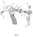
- FIG. 1is an exploded view of the components of a two-component dispensing applicator according to the principles of the present invention
- FIG. 2is a cross-sectional view of an applicator valve assembly in one embodiment of the present invention comprising a flow control element
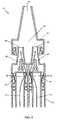
- FIG. 3is a cross-sectional view of another embodiment of the present invention comprising a flow control element
- FIG. 4is a cross-sectional view of yet another embodiment of the present invention comprising a flow control element.
- a reactive component dispensing applicator assembly in accordance with the principles of the present inventionis indicated generally as 10 in an exploded view of the assembly shown in FIG. 1 .
- the dispensing applicatorcomprises a base 20 having a handle and an opening for receiving valve assembly components 22 and 24 .
- the valve assembly components 22 and 24provide separate flow paths for two resin component materials, and each valve assembly component comprises a first and second passage corresponding to the first and second flow paths. While the embodiment shown provides for flow control of two components, it should be understood that the dispensing applicator could also be configured for dispensing more than two components where a catalyst or other resin component may be employed.
- a trigger 26provides for manually opening the valve assembly against the bias of a spring 27 , which biases the valve assembly in a normally closed position.
- the dispensing applicatormay also comprise components 28 and 29 for locking the trigger or locking the resin component supply lines in place.
- the dispensing applicator 10also comprises a nozzle (not shown in FIG. 1 ) that attaches to the end of the valve component 22 . The separate flow of the two resin components are received in a mixing chamber in the nozzle, through which the mixed components are dispensed.
- the dispensing applicator 10may further comprise at least one unidirectional flow control band 60 in at least one of the flow paths to prevent the occurrence of crossover flow from one flow path to another, where the flow control band is disposed around a peripheral element having at least one opening.
- the separate flow paths 32 and 34 of the first and second resin componentsare shown in a cross-sectional view of a valve assembly 30 in one embodiment of the present invention.
- the first and second passages of the flow paths 32 and 34each comprise one or more exit openings 36 and 38 within a peripheral wall of each passage, respectively.
- Surrounding or extending around the periphery of the passage and the one or more openings in the peripheral wallis at least one unidirectional flow control band 60 that covers the one or more exit openings to prevent the crossover flow of a component from one flow path back through an exit opening to the other component flow path.
- the unidirectional flow control bands 60comprise a resilient band that is elastically biased against the one or more exit openings 36 and 38 in a normally closed position that does not permit the rearward flow of a component resin back through the exit openings 36 and 38 .
- the resilient flow control bands 60elastically expand away from the exit openings 36 and 38 under pressure resulting from the normal flow path directions 32 and 34 . This elastic expansion permits the resin components to flow through the exit openings 36 and 38 past the resilient flow control bands 60 towards the exit.
- the flow control bandmay alternately comprise an elastic band that is generally in the shape of an o-ring, which may be positioned in an o-ring groove around the periphery of a passage and may alternatively cover an opening within the groove.
- the valve assemblygenerally comprises first and second valves 40 and 42 in the first and second flow paths, and first and second valve exits 44 and 46 that lead to a mixing chamber 52 of a nozzle 50 .
- the resilient flow control bands 60prevent the rearward displacement of component material in the valves 40 and 42 through the exit openings 36 and 38 , such that one component under pressure cannot enter the valve exit and crossover into the flow path of the other component.
- the valve assembly 30 shown in FIG. 2therefore provides for one-directional flow control of the components towards the valve exits 40 and 42 , by using an inexpensive, easy to install resilient flow control band 60 .
- the separate flow paths 32 and 34 of the first and second resin componentsare shown in a cross-sectional view of a valve assembly 30 in another embodiment of the present invention.
- the first and second passages of the flow paths 32 and 34each comprise one or more exit openings 70 and 72 within a peripheral wall of each of the passages that lead to a mixing chamber 52 in a nozzle 50 .
- Surrounding or extending around the periphery of each passage and the one or more openings in the peripheral wallsis a unidirectional flow control band 60 that covers openings to prevent a component from one flow path from flowing back through an exit opening to the other component flow path.
- the unidirectional flow control bands 60comprise a resilient band that is elastically biased against the one or more exit openings 70 and 72 in a normally closed position that does not permit the rearward flow of a component resin back through the exit openings 70 and 72 .
- the resilient flow control bands 60elastically expand away from the exit openings 70 and 72 under pressure resulting from the normal flow path directions 32 and 34 . This elastic expansion permits the resin components to flow through the exit openings 70 and 72 past the resilient flow control bands 60 towards the mixing chamber 52 .
- the flow of first and second componentsis received in the mixing chamber 52 of the nozzle 50 , through which the mixed components are dispensed at the nozzle exit 54 .
- the resilient flow control bands 60prevent a component under pressure in the mixing chamber from flowing rearward through the exit openings 70 and 72 , such that flow one component cannot crossover and enter the flow path of the other component.
- the embodiment shown in FIG. 3also provides for one-directional flow control of the components towards the valve exits 70 and 72 , by using an inexpensive, easy to install resilient flow control band 60 .
- the separate flow paths 32 and 34 of the first and second resin componentsare shown in a cross-sectional view of a valve assembly 30 in yet another embodiment of the present invention.
- the flow paths 32 and 34each comprise one or more openings 80 and 82 within the peripheral walls of first and second nozzle inlet passages leading to a mixing chamber 52 in a nozzle 50 .
- a unidirectional flow control band 60Surrounding or extending around the periphery of each nozzle inlet passage and the openings 80 and 82 in the peripheral walls is a unidirectional flow control band 60 that covers the openings to prevent a component from one flow path from flowing back through an opening to the other component flow path.
- the unidirectional flow control bands 60comprise a resilient band that is elastically biased against the one or more openings 80 and 82 in a normally closed position that does not permit the rearward flow of a component resin back through the openings 80 and 82 .
- the resilient flow control bands 60elastically expand away from the openings 80 and 82 under pressure resulting from the normal flow path directions 32 and 34 . This elastic expansion permits the resin components to flow through the openings 80 and 82 past the resilient flow control bands 60 towards the mixing chamber 52 , and prevents a component under pressure in the mixing chamber 52 from flowing rearward through the openings 80 and 82 , such that flow one component cannot crossover and enter the flow path of the other component.
- the flow of first and second componentsis received in the mixing chamber 52 of the nozzle 50 , through which the mixed components are dispensed at the nozzle exit 54 .
- the embodiment shown in FIG. 4thus also provides for one-directional flow control of the components towards the openings 80 and 82 in the nozzle inlet passages, by using an inexpensive, easy to install resilient flow control band 60 .
- the nozzle 50 and flow control bands 60 of this embodimentunlike the dispensing applicator, are of minimal cost and can be easily replaced. It would therefore be desirable to include the one-directional flow control bands of the present invention on such a disposable, inexpensive component.
- Such a nozzle componentmay also be configured to be connected specifically to the dispensing applicator of the present invention, which includes one or more tabs 90 for uniquely securing the inventive nozzle to a dispensing applicator.
- the unidirectional flow control bands 60may also be positioned around the periphery of the inlet passages leading into the valve assembly, where the resin component supply lines connect to the inlets of the valve assembly.
- the inlet passages to the valve assemblyare much like the inlet passages to the nozzle 50 described above.
- Such inlet passages to the valve assemblymay comprise one or more openings through a peripheral wall of the inlet passage that may be covered by the unidirectional flow control bands 60 as taught in the above disclosed embodiments. Accordingly, the unidirectional flow control bands 60 may be employed anywhere along the flow path leading up to the mixing chamber.
Landscapes
- Engineering & Computer Science (AREA)
- Mechanical Engineering (AREA)
- Nozzles (AREA)
- Processing And Handling Of Plastics And Other Materials For Molding In General (AREA)
- Multiple-Way Valves (AREA)
- Coating Apparatus (AREA)
Abstract
Description
Claims (14)
Priority Applications (1)
| Application Number | Priority Date | Filing Date | Title |
|---|---|---|---|
| US11/221,409US7559440B2 (en) | 2004-09-07 | 2005-09-07 | Anti-crossover dispensing applicator |
Applications Claiming Priority (2)
| Application Number | Priority Date | Filing Date | Title |
|---|---|---|---|
| US60761304P | 2004-09-07 | 2004-09-07 | |
| US11/221,409US7559440B2 (en) | 2004-09-07 | 2005-09-07 | Anti-crossover dispensing applicator |
Publications (2)
| Publication Number | Publication Date |
|---|---|
| US20060076361A1 US20060076361A1 (en) | 2006-04-13 |
| US7559440B2true US7559440B2 (en) | 2009-07-14 |
Family
ID=36036969
Family Applications (1)
| Application Number | Title | Priority Date | Filing Date |
|---|---|---|---|
| US11/221,409Expired - Fee RelatedUS7559440B2 (en) | 2004-09-07 | 2005-09-07 | Anti-crossover dispensing applicator |
Country Status (2)
| Country | Link |
|---|---|
| US (1) | US7559440B2 (en) |
| WO (1) | WO2006029191A2 (en) |
Cited By (13)
| Publication number | Priority date | Publication date | Assignee | Title |
|---|---|---|---|---|
| US20060060609A1 (en)* | 2004-09-17 | 2006-03-23 | Dobbs Douglas B | Dispenser having elastomer discharge valve |
| USD619439S1 (en)* | 2009-12-29 | 2010-07-13 | Graco Minnesota Inc. | Plural-component mechanical purge applicator |
| US20100270400A1 (en)* | 2009-04-22 | 2010-10-28 | Twenty Ten, Llc | Dispensing device |
| US8596498B2 (en) | 2011-05-02 | 2013-12-03 | Mouse Trap Design, Llc | Mixing and dispensing device |
| US20140048560A1 (en)* | 2012-08-16 | 2014-02-20 | Fomo Products, Inc. | Dual polymer needles for disposable foam dispensing gun |
| US20150122915A1 (en)* | 2010-05-07 | 2015-05-07 | Duerr Systems, Gmbh | Atomizer with a lattice mixer |
| WO2016007908A1 (en)* | 2014-07-10 | 2016-01-14 | Automatic Bar Controls, Inc. | Mixing nozzle for a blended beverage for a multiple flavor beverage dispensing system |
| US9546037B1 (en)* | 2015-06-24 | 2017-01-17 | Icp Adhesives And Sealants, Inc. | Modular foam dispensing gun |
| US9649650B2 (en) | 2013-11-07 | 2017-05-16 | Mouse Trap Design, Llc | Mixing and dispensing device |
| US10639656B1 (en) | 2015-10-16 | 2020-05-05 | Gary M. Hammerlund | Crossover prevention valve |
| US11213840B2 (en)* | 2017-05-01 | 2022-01-04 | Wagner Spray Tech Corporation | Mixer design for a plural component system |
| US11857994B1 (en) | 2015-10-16 | 2024-01-02 | Gary M. Hammerlund | Crossover prevention valve |
| US11911787B1 (en) | 2019-08-16 | 2024-02-27 | Gary Hammerlund | Split manifold and method for multiple part fluid applications |
Families Citing this family (5)
| Publication number | Priority date | Publication date | Assignee | Title |
|---|---|---|---|---|
| GB0417593D0 (en)* | 2004-08-06 | 2004-09-08 | Cox Ltd | Dispensing gun |
| FR3045298B1 (en) | 2015-12-17 | 2018-01-26 | L'oreal | APPARATUS FOR TREATING HUMAN KERATINIC MATERIALS |
| FR3045296B1 (en)* | 2015-12-17 | 2018-01-26 | L'oreal | DEVICE FOR THE TREATMENT OF HUMAN KERATINIC MATERIALS, PARTICULARLY USING AN ELECTRICAL CURRENT |
| FR3045289B1 (en) | 2015-12-17 | 2021-09-03 | Oreal | DEVICE FOR TREATMENT OF HUMAN KERATINIC MATERIALS, IN PARTICULAR USING AN ELECTRIC CURRENT |
| US10351334B1 (en)* | 2018-02-23 | 2019-07-16 | Icp Adhesives And Sealants, Inc. | Fluid dispensing device |
Citations (13)
| Publication number | Priority date | Publication date | Assignee | Title |
|---|---|---|---|---|
| US2715980A (en)* | 1950-10-09 | 1955-08-23 | Leo M Harvey | Liquid handling dispenser |
| US3303970A (en)* | 1964-07-14 | 1967-02-14 | Jerome Marrow | Device for simultaneously dispensing from plural sources |
| US4602726A (en)* | 1979-12-31 | 1986-07-29 | George Goda | Dispensing device |
| US4607764A (en)* | 1984-10-31 | 1986-08-26 | Trinity Foundation | Fluent product extraction system |
| US5163584A (en) | 1990-12-18 | 1992-11-17 | Polyfoam Products, Inc. | Method and apparatus for mixing and dispensing foam with injected low pressure gas |
| US5180082A (en) | 1991-10-17 | 1993-01-19 | Flexible Products Company | Foam dispensing gun with improved dispenser module |
| US5462204A (en)* | 1994-03-29 | 1995-10-31 | Rhh Foam Systems, Inc. | Foam dispensing gun |
| US5660205A (en)* | 1994-12-15 | 1997-08-26 | Epstein; Alan B. | One-way valve |
| US5899362A (en)* | 1997-05-01 | 1999-05-04 | Moran; Michael J. | Method and apparatus for combining liquids |
| US6158624A (en) | 1997-08-07 | 2000-12-12 | The Clayton Corporation | Foam dispensing gun |
| US6305578B1 (en)* | 1999-02-26 | 2001-10-23 | Wella Aktiengesellshaft | Device for mixing, foaming and dispensing liquids from separate compressed-gas containers |
| US6527203B2 (en) | 1999-12-23 | 2003-03-04 | Paul Gregory Hurray | Two-component dispensing gun |
| US7243682B2 (en)* | 2003-10-02 | 2007-07-17 | Brandes Raymond V | Annular one-way valve |
Family Cites Families (4)
| Publication number | Priority date | Publication date | Assignee | Title |
|---|---|---|---|---|
| US4171007A (en)* | 1976-03-05 | 1979-10-16 | Societe Anonyme: La Telemecanique Electrique | Unidirectional flow limiter |
| US4237935A (en)* | 1978-12-14 | 1980-12-09 | Eaton Corporation | Hydraulic pressure relief valve and fluid isolator |
| US5762103A (en)* | 1996-10-24 | 1998-06-09 | Advanced Pressure Technology, Inc. | Tilting o-ring check valve |
| US6082586A (en)* | 1998-03-30 | 2000-07-04 | Deb Ip Limited | Liquid dispenser for dispensing foam |
- 2005
- 2005-09-07WOPCT/US2005/031821patent/WO2006029191A2/enactiveApplication Filing
- 2005-09-07USUS11/221,409patent/US7559440B2/ennot_activeExpired - Fee Related
Patent Citations (13)
| Publication number | Priority date | Publication date | Assignee | Title |
|---|---|---|---|---|
| US2715980A (en)* | 1950-10-09 | 1955-08-23 | Leo M Harvey | Liquid handling dispenser |
| US3303970A (en)* | 1964-07-14 | 1967-02-14 | Jerome Marrow | Device for simultaneously dispensing from plural sources |
| US4602726A (en)* | 1979-12-31 | 1986-07-29 | George Goda | Dispensing device |
| US4607764A (en)* | 1984-10-31 | 1986-08-26 | Trinity Foundation | Fluent product extraction system |
| US5163584A (en) | 1990-12-18 | 1992-11-17 | Polyfoam Products, Inc. | Method and apparatus for mixing and dispensing foam with injected low pressure gas |
| US5180082A (en) | 1991-10-17 | 1993-01-19 | Flexible Products Company | Foam dispensing gun with improved dispenser module |
| US5462204A (en)* | 1994-03-29 | 1995-10-31 | Rhh Foam Systems, Inc. | Foam dispensing gun |
| US5660205A (en)* | 1994-12-15 | 1997-08-26 | Epstein; Alan B. | One-way valve |
| US5899362A (en)* | 1997-05-01 | 1999-05-04 | Moran; Michael J. | Method and apparatus for combining liquids |
| US6158624A (en) | 1997-08-07 | 2000-12-12 | The Clayton Corporation | Foam dispensing gun |
| US6305578B1 (en)* | 1999-02-26 | 2001-10-23 | Wella Aktiengesellshaft | Device for mixing, foaming and dispensing liquids from separate compressed-gas containers |
| US6527203B2 (en) | 1999-12-23 | 2003-03-04 | Paul Gregory Hurray | Two-component dispensing gun |
| US7243682B2 (en)* | 2003-10-02 | 2007-07-17 | Brandes Raymond V | Annular one-way valve |
Cited By (21)
| Publication number | Priority date | Publication date | Assignee | Title |
|---|---|---|---|---|
| US7654419B2 (en) | 2004-09-17 | 2010-02-02 | Meadwestvaco Calmar, Inc. | Dispenser having elastomer discharge valve |
| US20060060609A1 (en)* | 2004-09-17 | 2006-03-23 | Dobbs Douglas B | Dispenser having elastomer discharge valve |
| US20100270400A1 (en)* | 2009-04-22 | 2010-10-28 | Twenty Ten, Llc | Dispensing device |
| USD619439S1 (en)* | 2009-12-29 | 2010-07-13 | Graco Minnesota Inc. | Plural-component mechanical purge applicator |
| US20150122915A1 (en)* | 2010-05-07 | 2015-05-07 | Duerr Systems, Gmbh | Atomizer with a lattice mixer |
| US9539594B2 (en)* | 2010-05-07 | 2017-01-10 | Duerr Systems Gmbh | Atomizer with a lattice mixer |
| US8596498B2 (en) | 2011-05-02 | 2013-12-03 | Mouse Trap Design, Llc | Mixing and dispensing device |
| US9180476B2 (en) | 2011-05-02 | 2015-11-10 | Mouse Trap Design, Llc | Mixing and dispensing device |
| US20140048560A1 (en)* | 2012-08-16 | 2014-02-20 | Fomo Products, Inc. | Dual polymer needles for disposable foam dispensing gun |
| WO2014028718A3 (en)* | 2012-08-16 | 2014-04-10 | Fomo Products, Inc. | Dual polymer needles for disposable foam dispensing gun |
| US9079197B2 (en)* | 2012-08-16 | 2015-07-14 | Fomo Products, Inc. | Dual polymer needles for disposable foam dispensing gun |
| US9649650B2 (en) | 2013-11-07 | 2017-05-16 | Mouse Trap Design, Llc | Mixing and dispensing device |
| WO2016007908A1 (en)* | 2014-07-10 | 2016-01-14 | Automatic Bar Controls, Inc. | Mixing nozzle for a blended beverage for a multiple flavor beverage dispensing system |
| GB2543702A (en)* | 2014-07-10 | 2017-04-26 | Automatic Bar Controls Inc | Mixing nozzle for a blended beverage for a multiple flavor beverage dispensing system |
| US9714162B2 (en) | 2014-07-10 | 2017-07-25 | Automatic Bar Controls, Inc. | Mixing nozzle for a blended beverage for a multiple flavor beverage dispensing system |
| GB2543702B (en)* | 2014-07-10 | 2020-12-30 | Automatic Bar Controls Inc | Mixing nozzle for a blended beverage for a multiple flavor beverage dispensing system |
| US9546037B1 (en)* | 2015-06-24 | 2017-01-17 | Icp Adhesives And Sealants, Inc. | Modular foam dispensing gun |
| US10639656B1 (en) | 2015-10-16 | 2020-05-05 | Gary M. Hammerlund | Crossover prevention valve |
| US11857994B1 (en) | 2015-10-16 | 2024-01-02 | Gary M. Hammerlund | Crossover prevention valve |
| US11213840B2 (en)* | 2017-05-01 | 2022-01-04 | Wagner Spray Tech Corporation | Mixer design for a plural component system |
| US11911787B1 (en) | 2019-08-16 | 2024-02-27 | Gary Hammerlund | Split manifold and method for multiple part fluid applications |
Also Published As
| Publication number | Publication date |
|---|---|
| WO2006029191A2 (en) | 2006-03-16 |
| US20060076361A1 (en) | 2006-04-13 |
| WO2006029191A3 (en) | 2009-04-09 |
Similar Documents
| Publication | Publication Date | Title |
|---|---|---|
| US7559440B2 (en) | Anti-crossover dispensing applicator | |
| US10362740B2 (en) | Emitter and drip irrigation tube | |
| US6158624A (en) | Foam dispensing gun | |
| US6345776B1 (en) | Two-component dispensing gun | |
| US6772966B2 (en) | Adjustable hose end sprayer nozzle | |
| US7784715B2 (en) | Cartridge and admixing apparatus for a manually operable apparatus for spraying water mixed with an additive | |
| EP3479681B1 (en) | Emitter and tube for drip irrigation | |
| JPH0698285B2 (en) | Low cost mixing and dispensing gun for reaction chemical products | |
| US20080245897A1 (en) | Showerhead | |
| US5653261A (en) | Selector valve | |
| US5964415A (en) | Portable water--mixture dispenser | |
| WO2010004305A2 (en) | A connector for a gravity feed spray gun, a gravity feed spray gun and a method of preparing a spray paint | |
| EP3491913A1 (en) | Emitter and drip-irrigation tube | |
| JP7101045B2 (en) | Emitter and drip irrigation tube | |
| EP0999897B1 (en) | Spray gun with improved seal | |
| US6012650A (en) | Dispenser particularly useful for amateur gardeners | |
| US5377718A (en) | Selecting and dispensing valve | |
| US20070158476A1 (en) | Nozzle arrangements | |
| US11441689B2 (en) | Ceramic disc valve cartridge | |
| US10869435B2 (en) | Emitter and drip-irrigation tube | |
| US10806104B2 (en) | Emitter, and tube for drip irrigation | |
| KR200401806Y1 (en) | water flow converting apparatus for the bidet | |
| JP2015110874A (en) | Water discharge structure, and water service device | |
| JP6837377B2 (en) | Emitter and drip irrigation tubes | |
| EP3375526B1 (en) | Dispenser device of a jet of water |
Legal Events
| Date | Code | Title | Description |
|---|---|---|---|
| AS | Assignment | Owner name:CLAYTON CORPORATION, MISSOURI Free format text:ASSIGNMENT OF ASSIGNORS INTEREST;ASSIGNORS:RUESCHHOFF, KENNETH J.;MCBROOM, JAMES P.;REEL/FRAME:016935/0975 Effective date:20051216 | |
| STCF | Information on status: patent grant | Free format text:PATENTED CASE | |
| FEPP | Fee payment procedure | Free format text:PAT HOLDER CLAIMS SMALL ENTITY STATUS, ENTITY STATUS SET TO SMALL (ORIGINAL EVENT CODE: LTOS); ENTITY STATUS OF PATENT OWNER: SMALL ENTITY | |
| FPAY | Fee payment | Year of fee payment:4 | |
| FPAY | Fee payment | Year of fee payment:8 | |
| AS | Assignment | Owner name:DAP FOAM, INC., OHIO Free format text:ASSIGNMENT OF ASSIGNORS INTEREST;ASSIGNOR:CLAYTON CORPORATION;REEL/FRAME:041215/0611 Effective date:20161230 | |
| FEPP | Fee payment procedure | Free format text:MAINTENANCE FEE REMINDER MAILED (ORIGINAL EVENT CODE: REM.); ENTITY STATUS OF PATENT OWNER: SMALL ENTITY | |
| LAPS | Lapse for failure to pay maintenance fees | Free format text:PATENT EXPIRED FOR FAILURE TO PAY MAINTENANCE FEES (ORIGINAL EVENT CODE: EXP.); ENTITY STATUS OF PATENT OWNER: SMALL ENTITY | |
| STCH | Information on status: patent discontinuation | Free format text:PATENT EXPIRED DUE TO NONPAYMENT OF MAINTENANCE FEES UNDER 37 CFR 1.362 | |
| FP | Lapsed due to failure to pay maintenance fee | Effective date:20210714 |