US7559356B2 - Electrokinetic pump driven heat transfer system - Google Patents
Electrokinetic pump driven heat transfer systemDownload PDFInfo
- Publication number
- US7559356B2 US7559356B2US10/827,799US82779904AUS7559356B2US 7559356 B2US7559356 B2US 7559356B2US 82779904 AUS82779904 AUS 82779904AUS 7559356 B2US7559356 B2US 7559356B2
- Authority
- US
- United States
- Prior art keywords
- heat
- conduit
- exchangers
- transfer system
- primary
- Prior art date
- Legal status (The legal status is an assumption and is not a legal conclusion. Google has not performed a legal analysis and makes no representation as to the accuracy of the status listed.)
- Expired - Fee Related, expires
Links
Images


Classifications
- G—PHYSICS
- G06—COMPUTING OR CALCULATING; COUNTING
- G06F—ELECTRIC DIGITAL DATA PROCESSING
- G06F1/00—Details not covered by groups G06F3/00 - G06F13/00 and G06F21/00
- G06F1/16—Constructional details or arrangements
- G06F1/20—Cooling means
- F—MECHANICAL ENGINEERING; LIGHTING; HEATING; WEAPONS; BLASTING
- F04—POSITIVE - DISPLACEMENT MACHINES FOR LIQUIDS; PUMPS FOR LIQUIDS OR ELASTIC FLUIDS
- F04B—POSITIVE-DISPLACEMENT MACHINES FOR LIQUIDS; PUMPS
- F04B19/00—Machines or pumps having pertinent characteristics not provided for in, or of interest apart from, groups F04B1/00 - F04B17/00
- F04B19/006—Micropumps
- F—MECHANICAL ENGINEERING; LIGHTING; HEATING; WEAPONS; BLASTING
- F28—HEAT EXCHANGE IN GENERAL
- F28D—HEAT-EXCHANGE APPARATUS, NOT PROVIDED FOR IN ANOTHER SUBCLASS, IN WHICH THE HEAT-EXCHANGE MEDIA DO NOT COME INTO DIRECT CONTACT
- F28D15/00—Heat-exchange apparatus with the intermediate heat-transfer medium in closed tubes passing into or through the conduit walls ; Heat-exchange apparatus employing intermediate heat-transfer medium or bodies
- F28D15/02—Heat-exchange apparatus with the intermediate heat-transfer medium in closed tubes passing into or through the conduit walls ; Heat-exchange apparatus employing intermediate heat-transfer medium or bodies in which the medium condenses and evaporates, e.g. heat pipes
- F28D15/0266—Heat-exchange apparatus with the intermediate heat-transfer medium in closed tubes passing into or through the conduit walls ; Heat-exchange apparatus employing intermediate heat-transfer medium or bodies in which the medium condenses and evaporates, e.g. heat pipes with separate evaporating and condensing chambers connected by at least one conduit; Loop-type heat pipes; with multiple or common evaporating or condensing chambers
- C—CHEMISTRY; METALLURGY
- C02—TREATMENT OF WATER, WASTE WATER, SEWAGE, OR SLUDGE
- C02F—TREATMENT OF WATER, WASTE WATER, SEWAGE, OR SLUDGE
- C02F1/00—Treatment of water, waste water, or sewage
- C02F1/02—Treatment of water, waste water, or sewage by heating
- C—CHEMISTRY; METALLURGY
- C02—TREATMENT OF WATER, WASTE WATER, SEWAGE, OR SLUDGE
- C02F—TREATMENT OF WATER, WASTE WATER, SEWAGE, OR SLUDGE
- C02F1/00—Treatment of water, waste water, or sewage
- C02F1/46—Treatment of water, waste water, or sewage by electrochemical methods
- C02F1/461—Treatment of water, waste water, or sewage by electrochemical methods by electrolysis
- C02F1/46104—Devices therefor; Their operating or servicing
- C02F1/46109—Electrodes
- C02F2001/46128—Bipolar electrodes
- F—MECHANICAL ENGINEERING; LIGHTING; HEATING; WEAPONS; BLASTING
- F28—HEAT EXCHANGE IN GENERAL
- F28F—DETAILS OF HEAT-EXCHANGE AND HEAT-TRANSFER APPARATUS, OF GENERAL APPLICATION
- F28F2250/00—Arrangements for modifying the flow of the heat exchange media, e.g. flow guiding means; Particular flow patterns
- F28F2250/08—Fluid driving means, e.g. pumps, fans
- G—PHYSICS
- G06—COMPUTING OR CALCULATING; COUNTING
- G06F—ELECTRIC DIGITAL DATA PROCESSING
- G06F2200/00—Indexing scheme relating to G06F1/04 - G06F1/32
- G06F2200/20—Indexing scheme relating to G06F1/20
- G06F2200/201—Cooling arrangements using cooling fluid
Definitions
- the present inventionrelates to heat transfer systems, and more particularly to a system for heat transfer employing an electrokinetic pump.
- Heat reduction systemstypically remove heat from a source at an elevated temperature such as, for example, a computer processor, and exhaust the heat from the source to a heat sink having a lower temperature, such as ambient air temperature. By this heat transfer process, the source of heat is maintained at a finite temperature above the sink temperature. Modern electronic systems typically contact a finned heat sink to the source of heat and flow air across the heat sink to remove excess heat. Faster processors and more high power electronics in today's computer cases generate more heat and raise the air temperature within the computer case substantially higher than ambient air temperature. This makes the sink temperature (i.e., the air within the case) higher and thus raises the operating temperature of the components within the case.
- heat pipesit is known to use heat pipes to assist in heat exchange.
- a heat pipeis a sealed conduit partially filled with liquid that has a wicking structure along the inside walls.
- One end of the heat pipeis heated and the other end cooled.
- Liquidevaporates from the heated end, and the resulting vapor flows down the core of the heat pipe to be condensed at the cooled end. Liquid is resupplied to the heated end by wicking along the conduit walls.
- heat pipesare attractive, because they are fully sealed and have no mechanical moving parts, they have limitations such as limited heat flux capacity, sensitivity to orientation and the need for a rigid conduit. Additionally, the wick structure can be expensive and hard to manufacture reliably.
- a known alternative to the heat pipeis a capillary-pumped-loop, also called the pulsating-heat-pipe or “PHP.” This alternative is described in U.S. Pat. Nos. 4,921,041 and 5,219,020.
- the pulsating heat pipesare used in a fashion similar to a conventional heat pipe.
- the pulsating heat pipeis a conduit that is sealed and is partially filled with liquid.
- the pulsating heat pipeis different than a conventional heat pipe in that the pulsating heat pipe does not employ an internal wicking structure.
- the liquid within the conduitis naturally distributed as liquid-vapor slugs.
- a portion, or portions, of the pulsating heat pipeis heated and another portion, or portions, of the pulsating heat pipe are cooled.
- the production of vapor at the heated portionsraises the pressure locally and this causes motion of the liquid slugs along the conduit. This motion serves to move the liquid from heated to cooled terminals of the device.
- heat pipesthere are limitations with maximum heat flux, a strong sensitivity to orientation, and a strong sensitivity to the amount of liquid inside of the conduit.
- the present inventionis directed to a heat transfer system having a primary heat exchanger for receiving heat from a heat source; a secondary heat exchanger for exhausting heat to a heat sink; a conduit connecting the primary heat exchanger and the secondary heat exchanger; and an electrokinetic pump for pumping a heat exchange fluid between the primary heat exchanger and the secondary heat exchanger through the conduit.
- the present inventioncan further include a heat exchange fluid in the heat exchangers and the conduit.
- a controllercan be coupled to the electrokinetic pump.
- the controllercan operate the electrokinetic pump in a cyclic mode.
- the heat transfer systemhas a plurality of secondary heat exchangers.
- the heat transfer systemhas a plurality of primary heat exchangers and a plurality of secondary heat exchangers.
- the plurality of primary heat exchangers and the plurality of secondary heat exchangerscan be connected in series along a single flow path and operated thermally in parallel.
- the plurality of primary heat exchangers and the plurality of secondary heat exchangerscan be connected in parallel along two or more flow paths.
- the heat transfer fluidcan function as an acceptable electrolyte for the electrokinetic pump.
- the heat exchange fluidis isolated from the electrolyte used in the electrokinetic pump by a flexible member.
- the heat transfer fluidis water.
- the heat transfer systemcan utilize a single-phase heat exchange fluid or a multiphase heat exchange fluid.
- the present inventionis also directed to a method of removing heat using the heat exchange system described herein.
- a primary heat exchangeris placed in thermal communication with a heat source.
- a secondary heat exchangeris placed in thermal communication with a heat sink.
- a pumpis operated to move a heat exchange fluid in the primary heat exchanger through a conduit to the secondary heat exchanger and to move the heat exchange fluid in the secondary heat exchanger through the conduit to the primary heat exchanger.
- the pumpcan be operated to move the heat exchange fluid unidirectionally. Alternatively, the pump can be operated in a cyclic mode.
- FIG. 1is a schematic diagram of a heat transfer system according to a first embodiment of the present invention employing a single primary heat exchanger and a single secondary heat exchanger;
- FIG. 2is a schematic diagram of a heat transfer system according to a second embodiment of the present invention employing two secondary heat exchangers;
- FIG. 3is a schematic diagram of a heat transfer system according to a third embodiment of the present invention employing two primary heat exchangers and four secondary heat exchangers;
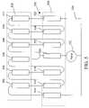
- FIG. 4is a schematic diagram of a heat transfer system according to a fourth embodiment of the present invention.
- FIG. 5is a schematic diagram of a heat transfer system according to a fifth embodiment of the present invention.
- FIG. 6is a side view of a first heat exchanger usable with the present invention.
- FIG. 7is a cross-sectional view of the heat exchanger of FIG. 6 taken along line VII-VII;
- FIG. 8is a side view of a second heat exchanger usable in the present invention.
- FIG. 9is a cross-sectional view of the heat exchanger of FIG. 8 taken along line IX-IX;
- FIG. 10is a side view of a third heat exchanger usable with the present invention.
- FIG. 11is a cross-sectional view of the heat exchanger of FIG. 10 taken along line XI-XI;
- FIG. 12is schematic diagram of an electrokinetic pump usable with the present invention.
- the term “primary heat exchanger”refers to a heat exchanger in thermal communication with a heat source.
- the term “secondary heat exchanger”refers to a heat exchanger in thermal communication with a heat sink.
- the term “coupled”means operatively connected to and does not require “coupled” objects to be in direct physical contact with each other.
- the present inventionis directed to a heat transfer system 100 .
- the heat transfer system 100has a primary heat exchanger 102 in thermal communication with a heat source 104 and a secondary heat exchanger 106 in thermal communication with a heat sink 108 .
- a conduit 110couples the primary heat exchanger 102 to the secondary heat exchanger 106 .
- a heat exchange fluidis pumped through the conduit 110 by an electrokinetic pump 112 coupled to a controller 114 . While there are many possible heat exchange fluids, the preferable fluid is water, from the standpoint of heat transfer properties, and also from the standpoint of avoiding noxious liquids in the case of leakage and for final disposal of the system.
- FIG. 2is a schematic diagram of a heat transfer system 200 according to a second embodiment of the present invention.
- heatis received at a primary exchanger 202 .
- the heat received by the primary exchanger 202is carried by liquid motion of a heat exchange fluid through two conduits 204 , 206 from the primary heat exchanger 202 to secondary heat exchangers 208 , 210 where the heat is exhausted.
- the motion of the liquidis produced by an electrokinetic pump 212 coupled to the secondary heat exchangers 208 , 210 by two pump conduits 214 , 216 .
- the pump 212can pump the fluid uni-directionally.
- the pumpcan operate in a cyclic mode, where in one half of the cycle the heat exchange fluid is directed towards one secondary exchanger, and where in the other half of the cycle the heat exchange fluid is directed toward the other secondary exchanger.
- the system 200can operate in a single-phase mode where all of the heat exchange fluid remains a liquid.
- the system 200can operate in a multiphase mode where some portion of the heat exchange fluid flowing through the primary exchanger as a liquid is evaporated into a gas and where some of a gas flowing into the secondary exchanger is condensed into a liquid.
- a higher degree of vaporizationrequires even less flow rate, for example a 75% vaporization requires a flow rate of about 6.4 mL/min to carry away 200 W of heat with a 20° C. rise in liquid temperature above the heat sink temperature.
- FIG. 3is a schematic diagram of a heat transfer system 300 according to a third embodiment of the present invention.
- two primary exchangers 302 and 304receive heat from a heat source. The heat received is exhausted through four secondary exchangers 306 , 308 , 310 , 312 .
- Two of the secondary heat exchangersare coupled in series to each primary heat exchanger along a conduit 314 .
- Two of the secondary heat exchangersare coupled in series.
- a single electrokinetic pump 316is coupled to the conduit 314 between the other two secondary heat exchangers. The electrokinetic pump 316 provides fluid flow to a heat exchange fluid in the conduit 314 .
- N primary and N+1 secondary exchangers in seriesgives an N-times reduction in the required flow rate needed to transfer a given amount of heat.
- FIG. 4is a heat transfer system 400 according to a fourth embodiment of the present invention.
- the systememploys five primary heat exchangers 402 , 404 , 406 , 408 , 410 and six secondary exchangers 412 , 414 , 416 , 418 , 420 , 422 coupled in series along a single flow path, operated thermally in parallel, and driven by a single electrokinetic pump 424 .
- the primary heat exchangersare in thermal contact with a heat source 426 and the secondary heat exchangers are in thermal contact with a heat sink 428 .
- the pump 424supplies a heat exchange fluid that flows through a conduit 430 in fluid communication with all of the primary heat exchangers and all of the secondary heat exchangers.
- the heat exchange fluidis carried through the first secondary exchanger 412 which is in thermal contact with the heat sink 428 , then to primary heat exchanger 402 which is in thermal contact with the heat source 426 .
- the heat exchange fluidis then carried to the second secondary exchanger 414 , followed by the second primary exchanger 404 , the third secondary exchanger 416 , the third primary exchanger 406 , the fourth secondary exchanger 418 , the fourth primary exchanger 408 , the fifth secondary exchanger 420 , the fifth primary exchanger 410 , and finally to the sixth secondary exchanger 422 .
- the heat exchange fluidis pumped from the sixth secondary exchanger 422 back to the pump 424 .
- the flow directionis reversed.
- the secondary heat exchangersare filled with liquid, and the primary exchangers are filled with some combination of liquid and vapor.
- liquid from the secondary exchangersis pushed into the primary exchangers where a part of the liquid vaporizes.
- Simultaneously vapor from the primary exchangersis drawn into the secondary exchangers where the vapor condenses.
- liquid from the secondary exchangersis driven into the primary exchangers and vapor from the primary exchangers is then drawn into the secondary exchangers.
- the internal volume of the secondary exchangers immediately connected to the pumpis greater than the amount of liquid displaced by the pump per stroke. This avoids drawing vapor into the pump. Additionally, it is preferable that the amount of liquid dispensed per pump stroke is sufficient to fill the primary exchangers. Therefore, it is preferable that the volume per stroke is about equal to the sum of the volume of the primary exchanger and the volume of the interconnecting conduit between the primary exchanger and the next upstream secondary exchanger.
- the secondary exchangers 412 , 422 closest to the pump 424can be the same as the other secondary exchangers.
- the secondary heat exchangers 412 , 422 closest to the pumphave a sufficiently large internal volume to avoid drawing vapor into the pump.
- the internal volume of the secondary heat exchangers 412 , 422 closest to the pumpis at least twice the volume delivered per pump stroke.
- the heat exchangerscan be of any type known in the art.
- the primary heat exchangersneed not be of the same type as the secondary heat exchangers.
- FIG. 5is a schematic diagram of a heat transfer system 500 according to a fifth embodiment of the present invention where the heat exchangers are coupled in parallel along two flow paths and operated thermally in parallel.
- the systemhas six primary exchangers 502 , 504 , 506 , 508 , 510 , 512 and seven secondary heat exchangers 514 , 516 , 518 , 520 , 522 , 524 , 526 .
- the primary heat exchangersare in thermal contact with a heat source 528 and the secondary heat exchangers are in thermal contact with a heat sink 530 . All of the heat exchangers are coupled together and to an electrokinetic pump 532 via a conduit 534 .
- the pump 532has two ports for input and output.
- a first port of the pump 532is coupled to both the first secondary heat exchanger 514 and the seventh secondary heat exchanger 526 .
- the first secondary heat exchangeris coupled to the first primary heat exchanger 502 , the flow path then extending through the second secondary heat exchanger 516 , the second primary heat exchanger 504 , the third secondary heat exchanger 518 , and to the third primary heat exchanger 506 .
- the seventh secondary heat exchanger 526is coupled to the sixth primary heat exchanger 512 , the flow path then extending through the sixth secondary heat exchanger 524 , the fifth primary heat exchanger 510 , the fifth secondary heat exchanger 522 , and to the fourth primary heat exchanger 508 .
- Both the third primary heat exchanger 506 and the fourth primary heat exchanger 508are coupled via a common conduit to the fourth secondary heat exchanger 520 .
- the fourth secondary heat exchanger 520is coupled to a second port of the pump 532 .
- the pumpcan be connected to one or more exchangers in parallel along two or more flow paths as shown in FIG. 5 where two such series are connected in parallel along two flow paths.
- the use of N primary exchangers arranged in seriesrequires the pump flow rate to meet the heat load demand where the pump operates into a pressure drop imposed by the series of exchangers.
- the same number of exchangerscan be arranged in parallel along two or more flow paths resulting in a decrease in the back pressure imposed on the pump.
- the same number of exchangerscan be arranged in parallel along two or more flow paths, and the available pump pressure can be employed to use a larger pressure drop per exchanger, thereby providing a more efficient and compact exchanger.
- a plurality of electrokinetic pumpscan be used to pump the heat exchange fluid.
- Heat exchangers usable with the present inventioncan be micro-channel heat exchangers or any other form of heat exchanger known in the art. Heat exchangers known in the art, and those detailed below can be utilized in the present invention as a means for receiving heat and as a means for exhausting heat.
- FIGS. 6 and 7show a first possible type of heat exchanger 600 usable with the present invention.
- heatis transferred by contact to a body 602 that contains a conduit 604 .
- the conduit 604has a first port 606 and a second port 608 .
- the conduit 604carries a heat exchange fluid.
- the conduit 604takes a serpentine path through the body 602 to decrease the heat transfer resistance of the heat exchanger.
- FIGS. 8 and 9show a second type of heat exchanger 700 usable with the present invention.
- heatis transferred by contact to a body 702 that contains a conduit 704 .
- the conduit 704has a first port 706 and a second port 708 .
- the conduit 704carries a heat exchange fluid.
- Portions of the internal walls of the body 702are fitted with a wick structure 710 that wicks liquid along the internal walls of the body.
- the wick structure 710can be a porous metal, screen, groove or any other wick structure as known in the art. Liquid naturally fills the wick structures leaving the conduit 704 free to carry off any vapor produced.
- FIGS. 10 and 11show a third type of heat exchanger 800 usable with the present invention.
- heatis transferred to the body 802 .
- the bodycontains a conduit 804 .
- the conduit 804has a first port 806 and a second port 808 .
- the conduit 804carries the heat exchange fluid.
- the conduit 804is subdivided into a number of parallel passageways 810 .
- One form of this style of heat exchangeris a microchannel heat exchanger. Such a heat exchanger is discussed in “High performance heat sinking for VLSI,” by D. B. Tuckerman and R. F. W. Pease, IEEE Electron Dev. Letts., vol. EDL-2, pp. 126-129 (1981), the entire contents of which are hereby incorporated herein by reference in their entirety.
- An exemplary electrokinetic pump 900is shown in FIG. 12 .
- An electrokinetic pump 900comprises a first electrode 902 , a second electrode 904 , and a conduit 906 .
- the conduit 906has a first end 908 which is adjacent to (i.e., is in contact with or separated from) the first electrode 902 and in communication with a first reservoir 910 .
- the first reservoir 910is in communication with a first port 912 of the electrokinetic pump.
- a second end 914 of the conduit 906is adjacent to (i.e., is in contact with or separated from) the second electrode 904 and in fluid communication with a second reservoir 916 .
- the second reservoir 916is in fluid communication with a second port 918 of the electrokinetic pump.
- the conduit 906is filled with a porous dielectric medium 919 .
- a power source 920is connected across the two electrodes 902 , 904 by leads 922 , 924 .
- the conduitWhen the conduit is filled with a suitable electrolyte solution, the application of a suitable electrical potential to the electrodes causes electroosmotic flow of the electrolyte solution through the conduit.
- the net flow rate of the electrolyte solutionis the electroosmotic flow modified by any other factors, e.g., hydrostatic pressure, affecting the flow rate.
- electrolyteis used to denote the electrolyte itself (for example, the compound such as an ionic salt) and the solvent in which the compound is dissolved; and the term “chemical change” is used to denote any chemical reaction involving the compound or the solvent or both.
- the reaction products produced by the chemical change of the electrolyteare undesirable because they can be gasses which must be vented and/or electrochemical products which dissolve in the electrolyte and change its composition, for example change its pH.
- Electrokinetic pumps usable with the present inventionoften contain only two electrodes.
- the electrokinetic pumpcan contain three or more electrodes, for example three electrodes, one pair of which are active in one period of operation and another pair of which are active in another period of operation.
- the electrokinetic pumpcan contain three or more electrodes with porous dielectric mediums having zeta potentials of opposite signs alternating between the electrodes.
- the electrodes in a devicecan be the same or different. When one of the electrodes in a capacitive electrode pair is composed of non-capacitive material, there is chemical change of the electrolyte at the non-capacitive electrode but not at the capacitive electrode.
- the electrodessupply the current required, even for high flow rates, e.g., greater than 1 mL/min, without significant electrolysis of the pump fluid or significant evolution of the pH of the pump fluid. Avoidance of significant pH evolution of the pump fluid can be accomplished by not allowing the voltage drop between the electrodes and the liquid to exceed the threshold for Faradaic electrochemical reactions, which start at approximately 1.2V for water.
- the double-layer capacitance or the pseudocapacitance of the electrodespreferably is charged prior to the beginning of bulk Faradaic processes.
- Typical values of double layer capacaitance of a plane metal surfaceare 20 to 30 micro Farads/cm 2 . This value can be substantially increased using methods well-known in the electrochemical arts (e.g. surface roughening, surface etching, platinization of platinum).
- the double-layer capacitance of the electrodesis preferably at least 10 ⁇ 4 farads/cm 2 and more preferably at least 10 ⁇ 2 farads/cm 2 .
- the desired strategyis to apply a current to the electrodes to produce a desired flow rate while charging the double-layer capacitance of the electrodes during the first half of the pump cycle.
- the polarity of the applied fieldis then changed before Faradaic processes begin, thereby discharging the double-layer capacitance of the electrodes and then recharging the electrodes with the opposite polarity causing the pump fluid to flow in the opposite direction during the second half of the pump cycle.
- At least one of the electrodes in a capacitive electrode pairis composed of a capacitive material, i.e. a material which exhibits double-layer capacitance or pseudo-capacitance.
- each of the electrodescomprises a capacitive material.
- each of the electrodes in a capacitive electrode paircontributes at least 30% of the capacitance between them.
- the capacitance of conventional double-layer capacitive materialsresults from the ability to store electrical energy in an electrochemical double layer at the electrode-electrolyte interface.
- Pseudocapacitive materialsare materials which can also store electrical energy, but through a different mechanism.
- An electrode or pair of electrodescan comprise both double-layer materials and pseudocapacitive materials.
- a preferred double-layer capacitive material for the electrodesis carbon having a very large ratio of microscopic surface area to geometric surface area.
- Carbon paper impregnated with carbon aerogelis particularly preferred.
- Other carbon materials that can be usedinclude carbon aerogel, e.g. monolithic carbon aerogel foam, woven carbon cloth, carbon fibers (e.g. pyrolized polyacrylonitrile fibers and pyrolized cellulose fibers), carbon nanotubes, carbon black, a polymer having carbon particles dispersed therein, carbon nanotubes, and frits of carbon particles.
- conductive materials having a high microscopic surface areafor example sintered metals, nanoporous metals, for example nanaporous gold, perforated plates, porous frits, porous membranes, deLevi brushes, and metals that have been treated to increase their surface area, for example by surface roughening, surface etching or platinization.
- pseudocapacitive materialsare metal oxides which are relatively insoluble in water and many other solvents, and in which the metal can adopt different oxidation states, for example cobalt, manganese, iridium, vanadium and ruthenium oxides. In operation of electrodes comprising such materials, a redox reaction takes place in the solid phase of the electrode, with uptake or release of a specific ion, e.g. H + for ruthenium oxide.
- Other pseudocapacitive materialsare solid materials into which a soluble ion, e.g.
- Li +can be inserted (“intercalation”) or from which a soluble ion can be dispensed (“de-intercalation”), for example manganese nitrides, titanium molybdenum disulfides, carbon, and conducting polymers and such as polyaniline, polythiophene and polyacetylene.
- a soluble ionfor example manganese nitrides, titanium molybdenum disulfides, carbon, and conducting polymers and such as polyaniline, polythiophene and polyacetylene.
- Some pseudocapacitive materialsreact with water, and should, therefore, be used with non-aqueous electrolytes. In operation of electrodes comprising such materials, a redox reaction takes place in the solid phase of the electrolyte, and results in release or uptake of ions. When the electrode is composed of a pseudocapacitive material, care is needed
- the electrode materialis preferably insoluble in the electrolyte and has an electrical conductivity substantially greater than, preferably at least 100 times, the conductivity of the electrolyte.
- the conductivity of a carbon aerogel foamis about 100 mho/cm and a conductivity of a typical electrolyte, 5 mM NaCl, is about 0.5 ⁇ 10 ⁇ 3 mho/cm.
- the electrodesare preferably washed, and, if necessary, leached in the electrolyte before use. Porous electrodes are preferably degassed after such treatment.
- the electrolyteflows through the electrodes when the pump is operating.
- the electrodespreferably at least 25%, and more preferably at least 50%, of the geometric area of the electrode is open and/or the flow permeability of the electrode material is at least 10 times, and particularly at least 100 times, the flow permeability of the porous dielectric medium in the conduit.
- Such electrodescan also be used when the electrolyte does not need to flow through the electrode.
- the electrodehas a thickness of at least 0.5 mm, preferably at least 1 mm, particularly at least 2 mm.
- the rate at which the electrolyte flows through the conduitcan be constant or variable.
- the power applied to the electrodescan be controlled with respect to voltage or current, or at some times one and at other times the other.
- the flow ratedepends upon the potential drop over the conduit, which decreases as the capacitive electrodes are charged, particularly when the applied potential is comparable to the electrolysis potential.
- the power applied to the electrodescan be increased to compensate for this decrease, for example by using a constant current source, or by monitoring the potential drop across the conduit by means of sensors placed near the ends of the porous dielectric medium in the conduit (but preferably outside the direct field path between the electrode and the porous dielectric medium), and adjusting the power source appropriately.
- the powercan alternatively or additionally be adjusted in response to temperature or another variable, for example to produce a desired heat transfer rate, temperature, flow rate, pressure, for example in response to a signal from a measurement device, e.g. through a feedback loop.
- the cycle duration and the power supplycan be controlled so that the total charge supplied in each cycle is the same, in order to ensure that the electrodes do not acquire a time-average positive or negative potential.
- the product of current and duration of each of the cyclesis preferably the same.
- the time-integrated current of each of the cyclesis preferably the same.
- the capacitance of an electrodedepends on its composition and on the size and shape of its active electrochemical surface.
- the area of the active electrochemical surface of the electrodeis preferably 0.6 to 1.1 times, e.g. 0.8 to 1.0 times, the cross-sectional area of the conduit.
- the term “equivalent diameter”is used herein to mean the diameter of a circle having the same area as the cross-sectional area of the conduit.
- the area of the active electrochemical surface of the electrodeis preferably at least 2 times, particularly at least 10 times, especially at least 100 times, the cross-sectional area of the conduit.
- the rate at which charge is transferred to a particular area on the electrodeis proportional to the current flux at that area, and as soon as any area of the electrode reaches the liquid electrolysis potential, chemical change of the electrolyte commences at that area.
- the run time of the devicei.e. the time for which the device will operate without chemical change of the electrolyte
- the run time of the devicedepends on the highest current flux at any point on the electrode. Therefore, the smaller the maximum current flux on the electrode, the longer the run time.
- the smaller the variation in current flux over the electrodethe greater the total amount of charge that can be transferred to an electrode having a particular geometric size.
- the electrodesare preferably shaped and positioned so that the maximum current flux at any point on the electroactive surface of the electrode is at most 2 times, preferably at most 1.2 times, the minimum current flux at any point on the active surface.
- the maximum current flux at any point on the electroactive surface of the electrodeis at most 2 times, preferably at most 1.2 times, the minimum current flux at any point on the active surface.
- the conduitis a short tube which is filled by a transverse disc of porous dielectric material.
- the electrodesare preferably substantially planar discs which lie on either side of the conduit and are parallel to each other and to the disc of porous dielectric material.
- the electrodespreferably cover at least 60%, particularly at least 80%, of the disc of porous dielectric material.
- the current flux on the electrodes in such devicescan be relatively high, for example at least 0.05, e.g. 0.2 to 1, milliamps per cm 2 .
- the conduitis a relatively long narrow tube, for example of round or rectangular (including square) cross-section, filled by porous dielectric material.
- the current flux on the electrodes in such devicescan be relatively low, for example less than 0.05 milliamps per cm 2 , less than 20 microamps per cm 2 , or less than 2 microamps per cm 2 , e.g. 1 to 20 microamps per cm 2 .
- the electrodecan for example be:
- annular memberplaced concentrically around the end of a conduit of circular cross section or around the end of a via of circular cross section through which the current flows after leaving the conduit;
- the inner diameter of the spherical shellcan for example be 4 to 6 times, e.g. about 5 times, the diameter of the conduit;
- the inner diameter of the cylindrical shellcan for example be 4 to 6 times, e.g. about 5 times, the short axis of the rectangular cross-section;
- the ends of the cylindrical shellcan be open or each end can be closed by at least part of the inner concave surface of a hemispherical shell which extends away from the conduit and is positioned so that its center is at one end of the rectangular cross-section of the conduit or via.
- Planar electrodescan be divided from sheet materials, for example sheet materials obtained by impregnating carbon aerogel into a carbon-fiber paper or by coating ruthenium oxide onto a metal sheet, screen or porous metal frit. Three-dimensional electrodes can be directly cast into the desired shape or machined out of a block, e.g. a carbon aerogel foam.
- the leads to the electrodesare preferably placed and/or insulated so that they do not influence the electrical field in the electrolyte.
- the deviceis preferably designed so that the voltage drop across the conduit is at least 10%, more preferably at least 50%, and more preferably at least 85%, of the voltage drop between the electrodes.
- the devicecan include sensors for measuring the voltage drop across the conduit, and control means connected to the power supply to control the voltage supplied to the electrodes, in order to ensure that the electrolyte flows at a desired rate.
- the conduit between the electrodescan be of any shape.
- the conduitis relatively long and narrow. In other embodiments, it is relatively short and wide.
- the conduitpreferably contains a porous dielectric medium.
- the porous dielectric mediumcan extend out from the conduit, be flush with the end of the conduit, or terminate within the conduit.
- the conduitit is also possible for the conduit to be an “open” conduit, i.e. a conduit which does not contain any packing material, or to be composed of a plurality of fine parallel channels.
- each of the two sectionshaving one end adjacent to an electrode and an opposite end communicating with a central chamber which does not contain an electrode.
- Application of a suitable power source to the electrodes of such a devicecan cause the electrokinetic fluid in both sections to be pumped towards, or away from, the central chamber.
- Suitable porous dielectric mediumsare well-known to those skilled in the art, and can be organic, e.g. a porous polymer membrane or a phase-separated organic material, or inorganic, e.g. a porous sintered ceramic, a porous inorganic oxide (e.g. silica, alumina or titania) membrane or aerogel, packed silica beads, micromachined, stamped or embossed arrays, phase-separated porous glasses (e.g. Vycor), and phase-separated ceramics.
- organice.g. a porous polymer membrane or a phase-separated organic material
- inorganice.g. a porous sintered ceramic, a porous inorganic oxide (e.g. silica, alumina or titania) membrane or aerogel, packed silica beads, micromachined, stamped or embossed arrays, phase-separated porous glasses (e.g. Vycor),
- the pores in the porous dielectric mediumhave a diameter of 50 to 500 nm, for example about 200 nm, so that the conduit has a high stall pressure (for which small pores are desirable) but does not have substantial double-layer overlap (which can result if the pores are too small).
- Other preferred features for the porous dielectric mediumare a high zeta potential and a narrow pore size distribution.
- porous dielectric mediumsare the high purity alumina membranes sold under the tradename Anopore, and porous polyvinylidene fluoride (PVDF) membranes, for example those sold under the tradename Durapore, which can have a pore size of 100-200 nanometers, and which can be modified to be hydrophilic and have a zeta potential of ⁇ 30 to ⁇ 60 millivolts.
- PVDFpolyvinylidene fluoride
- the ionic strength of the electrolyteis preferably sufficient to provide a Debye length that is less than 0.1 times the diameter of the pores in the porous dielectric medium.
- the mobilities of the ions in the electrolyteare preferably less than 20 times, more preferably less than 3 times, and most preferably less than 1 time, the electroosmotic mobility of the porous dielectric medium.
- the porous dielectric mediumcan have either a positive or a negative zeta potential. Electrolytes containing polyvalent ions having a charge of opposite sign to the zeta potential of the porous dielectric medium are preferably avoided. For example, phosphates, borates and citrates are preferably avoided when the porous dielectric medium has a positive zeta potential, and barium and calcium ions are preferably avoided when the porous dielectric medium has a negative zeta potential.
- the devicescan contain one or more electrolyte-permeable internal spacers to separate components of the device.
- the electrical and flow resistances of such internal spacersare preferably much smaller than the electrical and flow resistances of the conduit.
- the spacersare generally composed of a large pore dielectric material, e.g. foamed polypropylene or acrylic polymer.
- the devicescan also contain one or more external supports to prevent the device from flexing during use and generally to maintain the components in a desired configuration.
- powermust be supplied to the electrodes through leads, and these leads are often integral parts of the device.
- the leadspreferably do not contact the electrolyte, and if they do, they are preferably composed of platinum or another electrochemically stable metal.
- the components of the devicecan be secured together in any way.
- theycan be laminated together to form a chip-like assembly, e.g. as described in copending, commonly assigned U.S. application Ser. No. 10/198,223 filed Jul. 17, 2002, by Paul, Neyer and Rehm the entire contents of which are incorporated herein by reference.
- the pumpcan be a direct pump, in which the only liquid is the electrolyte.
- a direct pumppropels the electrolyte along a flow path in which the electrolyte performs a useful function.
- a direct pumpcan be utilized when the heat exchange fluid functions as the electrolyte.
- the pumpcan be an indirect pump, in which pumping of the electrolyte causes flow of the heat exchange fluid in a part of the pump that is not subject to the electric field of the electrodes.
- the heat exchange fluidis a working fluid that does not function as the electrolyte.
- the devicein one form of indirect pump, includes a second conduit which is not subject to the electrical field of the electrodes and which has an open or openable end.
- the second conduitis filled with electrolyte, the open end of the second conduit is placed in contact with the heat exchange fluid, and the device is operated so that the heat exchange fluid is drawn into the second conduit.
- the heat exchange fluidis expelled from the second conduit by reversing the flow direction of the electrolyte.
- the pumping of the electrolytechanges the volume of a chamber containing the electrolyte, and thus changes the volume of an adjacent chamber so that heat exchange fluid is drawn into or expelled from the adjacent chamber.
- the chamberscan share an intermediate deformable member which changes shape as a result of flexure (e.g. a bellows) and/or stretching (e.g. a flexible diaphragm) and/or which comprises a piston/cylinder combination.
- the intermediate membercan for example be composed of a multilayer polymeric film, which can be metallized.
- the chamber which contains the electrolyte, and whose volume changescan be a chamber containing an electrode or a separate chamber, for example the central chamber in a device as described above in which two sections of the conduit communicate with a central chamber.
- Two or more pumpscan be connected in parallel for increased flow rates, or in series for increased pressures, e.g. as described in U.S. Pat. No. 6,719,535, the entire contents of which are hereby incorporated by reference herein.
- the electrokinetic pumpcan be operated in a cyclic mode.
- the electrokinetic pumpis first operated for a first period of time during which the electrolyte flows in one direction through the conduit; and thereafter the polarity of the power supply is reversed and the electrokinetic pump is operated for a second period of time during which the electrolyte flows in the opposite direction.
- Each period of timeis sufficiently short that there is no substantial chemical change of the electrolyte.
Landscapes
- Engineering & Computer Science (AREA)
- General Engineering & Computer Science (AREA)
- Mechanical Engineering (AREA)
- Physics & Mathematics (AREA)
- Thermal Sciences (AREA)
- Theoretical Computer Science (AREA)
- General Physics & Mathematics (AREA)
- Human Computer Interaction (AREA)
- Life Sciences & Earth Sciences (AREA)
- Sustainable Development (AREA)
- Structures Of Non-Positive Displacement Pumps (AREA)
- Other Air-Conditioning Systems (AREA)
- Electrolytic Production Of Non-Metals, Compounds, Apparatuses Therefor (AREA)
- Cooling Or The Like Of Electrical Apparatus (AREA)
Abstract
Description
Claims (12)
Priority Applications (4)
| Application Number | Priority Date | Filing Date | Title |
|---|---|---|---|
| US10/827,799US7559356B2 (en) | 2004-04-19 | 2004-04-19 | Electrokinetic pump driven heat transfer system |
| EP05779206AEP1738115A2 (en) | 2004-04-19 | 2005-04-14 | Electrokinetic pump driven heat transfer system |
| PCT/US2005/012757WO2005114061A2 (en) | 2004-04-19 | 2005-04-14 | Electrokinetic pump driven heat transfer system |
| JP2007509524AJP2007533170A (en) | 2004-04-19 | 2005-04-14 | Heat transfer system driven by electrodynamic pump |
Applications Claiming Priority (1)
| Application Number | Priority Date | Filing Date | Title |
|---|---|---|---|
| US10/827,799US7559356B2 (en) | 2004-04-19 | 2004-04-19 | Electrokinetic pump driven heat transfer system |
Publications (2)
| Publication Number | Publication Date |
|---|---|
| US20050230080A1 US20050230080A1 (en) | 2005-10-20 |
| US7559356B2true US7559356B2 (en) | 2009-07-14 |
Family
ID=35095074
Family Applications (1)
| Application Number | Title | Priority Date | Filing Date |
|---|---|---|---|
| US10/827,799Expired - Fee RelatedUS7559356B2 (en) | 2004-04-19 | 2004-04-19 | Electrokinetic pump driven heat transfer system |
Country Status (4)
| Country | Link |
|---|---|
| US (1) | US7559356B2 (en) |
| EP (1) | EP1738115A2 (en) |
| JP (1) | JP2007533170A (en) |
| WO (1) | WO2005114061A2 (en) |
Cited By (15)
| Publication number | Priority date | Publication date | Assignee | Title |
|---|---|---|---|---|
| US20060279706A1 (en)* | 2005-06-14 | 2006-12-14 | Bash Cullen E | Projection system |
| US20070144909A1 (en)* | 2002-10-18 | 2007-06-28 | Eksigent Technologies, Llc | Electrokinetic Pump Having Capacitive Electrodes |
| US20090109405A1 (en)* | 2007-03-02 | 2009-04-30 | Olympus Corporation | Holographic projection method and holographic projection device |
| US20090308752A1 (en)* | 2004-10-19 | 2009-12-17 | Evans Christine E | Electrochemical Pump |
| US7867592B2 (en) | 2007-01-30 | 2011-01-11 | Eksigent Technologies, Inc. | Methods, compositions and devices, including electroosmotic pumps, comprising coated porous surfaces |
| US8152477B2 (en) | 2005-11-23 | 2012-04-10 | Eksigent Technologies, Llc | Electrokinetic pump designs and drug delivery systems |
| US8251672B2 (en) | 2007-12-11 | 2012-08-28 | Eksigent Technologies, Llc | Electrokinetic pump with fixed stroke volume |
| US20120282112A1 (en)* | 2011-05-05 | 2012-11-08 | Nip Kenneth Kei-Ho | Ganging electrokinetic pumps |
| US8979511B2 (en) | 2011-05-05 | 2015-03-17 | Eksigent Technologies, Llc | Gel coupling diaphragm for electrokinetic delivery systems |
| US9314567B2 (en) | 2010-03-09 | 2016-04-19 | Board Of Regents Of The University Of Texas System | Electro-osmotic pumps, systems, methods, and compositions |
| US9416777B2 (en) | 2014-09-26 | 2016-08-16 | Becton, Dickinson And Company | Control circuits for electrochemical pump with E-valves |
| US9931462B2 (en) | 2012-09-21 | 2018-04-03 | Board Of Regents Of The University Of Texas System | Electro-osmotic pumps with electrodes comprising a lanthanide oxide or an actinide oxide |
| RU2806879C1 (en)* | 2022-06-30 | 2023-11-08 | Объединенный Институт Ядерных Исследований (Оияи) | Heat-conducting panel for liquid cooling systems of detector modules and method of its manufacturing |
| US20230417227A1 (en)* | 2022-06-25 | 2023-12-28 | EvansWerks, Inc. | Pumping systems and methods |
| US12363864B2 (en) | 2022-06-25 | 2025-07-15 | EvansWerks, Inc. | Cooling system and methods |
Families Citing this family (42)
| Publication number | Priority date | Publication date | Assignee | Title |
|---|---|---|---|---|
| US7297246B2 (en)* | 2004-04-22 | 2007-11-20 | Sandia Corporation | Electrokinetic pump |
| US7149085B2 (en)* | 2004-08-26 | 2006-12-12 | Intel Corporation | Electroosmotic pump apparatus that generates low amount of hydrogen gas |
| DE102006004887B4 (en)* | 2006-02-03 | 2010-07-22 | Karlsruher Institut für Technologie | Device for generating fluid flows, process for their preparation and their operation and their use |
| JP2007272294A (en)* | 2006-03-30 | 2007-10-18 | Nec Personal Products Co Ltd | Cooling device and information processor |
| KR101098735B1 (en)* | 2009-02-26 | 2011-12-23 | 충북대학교 산학협력단 | Micro Heat Exchanger Using Al Bubble Alloy |
| US8159065B2 (en) | 2009-03-06 | 2012-04-17 | Hynix Semiconductor Inc. | Semiconductor package having an internal cooling system |
| KR101046384B1 (en)* | 2009-03-06 | 2011-07-05 | 주식회사 하이닉스반도체 | Semiconductor package |
| CN102042774A (en)* | 2009-10-16 | 2011-05-04 | 杨泰和 | Heat absorbing or releasing device with flow paths distributed in staggered mode according to temperature difference |
| US20110094718A1 (en)* | 2009-10-22 | 2011-04-28 | Tai-Her Yang | Heat absorbing or dissipating device with double-scroll piping transmitting temperature difference fluid |
| EP2585784A4 (en) | 2010-06-24 | 2016-02-24 | Venmar Ces Inc | LIQUID / AIR MEMBRANE ENERGY EXCHANGER |
| EP2633378A1 (en)* | 2010-10-28 | 2013-09-04 | Asetek A/S | Liquid cooling system for an electronic system |
| US8358505B2 (en) | 2010-10-28 | 2013-01-22 | Asetek A/S | Integrated liquid cooling system |
| US8432691B2 (en)* | 2010-10-28 | 2013-04-30 | Asetek A/S | Liquid cooling system for an electronic system |
| US8915092B2 (en) | 2011-01-19 | 2014-12-23 | Venmar Ces, Inc. | Heat pump system having a pre-processing module |
| JP5776340B2 (en)* | 2011-06-06 | 2015-09-09 | 富士通株式会社 | Liquid transport device and semiconductor cooling device using the transport device |
| US9810439B2 (en) | 2011-09-02 | 2017-11-07 | Nortek Air Solutions Canada, Inc. | Energy exchange system for conditioning air in an enclosed structure |
| US9964346B2 (en)* | 2012-04-30 | 2018-05-08 | Modine Manufacturing Company | Space conditioning system with hot gas reheat, and method of operating the same |
| WO2014027406A1 (en)* | 2012-08-15 | 2014-02-20 | 富士通株式会社 | Heat-receiving device, cooling device, and electronic device |
| WO2014027405A1 (en) | 2012-08-15 | 2014-02-20 | 富士通株式会社 | Heat-receiving device, cooling device, and electronic device |
| US9816760B2 (en) | 2012-08-24 | 2017-11-14 | Nortek Air Solutions Canada, Inc. | Liquid panel assembly |
| WO2014112726A1 (en)* | 2013-01-15 | 2014-07-24 | 서강대학교산학협력단 | Electro-osmotic pump using reversible electrode reaction and fluid pumping system using same |
| US9772124B2 (en) | 2013-03-13 | 2017-09-26 | Nortek Air Solutions Canada, Inc. | Heat pump defrosting system and method |
| US9109808B2 (en) | 2013-03-13 | 2015-08-18 | Venmar Ces, Inc. | Variable desiccant control energy exchange system and method |
| US10352628B2 (en) | 2013-03-14 | 2019-07-16 | Nortek Air Solutions Canada, Inc. | Membrane-integrated energy exchange assembly |
| US10584884B2 (en) | 2013-03-15 | 2020-03-10 | Nortek Air Solutions Canada, Inc. | Control system and method for a liquid desiccant air delivery system |
| US11408681B2 (en) | 2013-03-15 | 2022-08-09 | Nortek Air Solations Canada, Iac. | Evaporative cooling system with liquid-to-air membrane energy exchanger |
| JP6239900B2 (en)* | 2013-08-22 | 2017-11-29 | 高砂熱学工業株式会社 | Heat source liquid supply method and heat source liquid supply system |
| EP3070331B1 (en)* | 2013-08-26 | 2019-02-27 | Sogang University Research Foundation | Electroosmotic pump and fluid pumping system having same |
| US10376841B2 (en)* | 2013-08-26 | 2019-08-13 | Sogang University Research & Business Development Foundation | Electroosmotic pump and fluid pumping system including the same |
| US10712024B2 (en) | 2014-08-19 | 2020-07-14 | Nortek Air Solutions Canada, Inc. | Liquid to air membrane energy exchangers |
| US11092349B2 (en) | 2015-05-15 | 2021-08-17 | Nortek Air Solutions Canada, Inc. | Systems and methods for providing cooling to a heat load |
| SG10201913923WA (en) | 2015-05-15 | 2020-03-30 | Nortek Air Solutions Canada Inc | Using liquid to air membrane energy exchanger for liquid cooling |
| WO2016207864A1 (en) | 2015-06-26 | 2016-12-29 | Nortek Air Solutions Canada, Inc. | Three-fluid liquid to air membrane energy exchanger |
| US9921618B2 (en)* | 2015-12-24 | 2018-03-20 | Intel Corporation | Cooling solution for a dock |
| SG10201913897RA (en) | 2016-03-08 | 2020-03-30 | Nortek Air Solutions Canada Inc | Systems and methods for providing cooling to a heat load |
| KR102006908B1 (en)* | 2016-06-28 | 2019-08-02 | 이오플로우(주) | Electroosmotic pump and system for pumping of fluid comprising thereof |
| AU2017410557A1 (en) | 2017-04-18 | 2019-12-05 | Nortek Air Solutions Canada, Inc. | Desiccant enhanced evaporative cooling systems and methods |
| AU2017410556A1 (en) | 2017-04-18 | 2019-12-05 | Nortek Air Solutions Canada, Inc. | Systems and methods for managing conditions in enclosed space |
| CN107918476A (en)* | 2017-12-29 | 2018-04-17 | 重庆欣璇网络科技有限公司 | A kind of radiating structure of computer |
| JP2020056407A (en)* | 2018-10-03 | 2020-04-09 | 株式会社村田製作所 | Pump and cooling substrate |
| WO2020071334A1 (en)* | 2018-10-03 | 2020-04-09 | 株式会社村田製作所 | Pump and cooling board |
| EP4132246A1 (en)* | 2021-07-23 | 2023-02-08 | Eaton Intelligent Power Limited | Corona discharge powered cooling |
Citations (116)
| Publication number | Priority date | Publication date | Assignee | Title |
|---|---|---|---|---|
| US2615940A (en) | 1949-10-25 | 1952-10-28 | Williams Milton | Electrokinetic transducing method and apparatus |
| US2644900A (en) | 1951-11-27 | 1953-07-07 | Jr Edward V Hardway | Electrokinetic device |
| US2644902A (en) | 1951-11-27 | 1953-07-07 | Jr Edward V Hardway | Electrokinetic device and electrode arrangement therefor |
| US2661430A (en) | 1951-11-27 | 1953-12-01 | Jr Edward V Hardway | Electrokinetic measuring instrument |
| US2995714A (en) | 1955-07-13 | 1961-08-08 | Kenneth W Hannah | Electrolytic oscillator |
| US3143691A (en) | 1958-11-28 | 1964-08-04 | Union Carbide Corp | Electro-osmotic cell |
| US3209255A (en) | 1960-04-22 | 1965-09-28 | Union Carbide Corp | Electro-osmotic current integrator with capillary tube indicator |
| US3298789A (en) | 1964-12-14 | 1967-01-17 | Miles Lab | Test article for the detection of glucose |
| US3427978A (en) | 1964-09-02 | 1969-02-18 | Electro Dynamics Inc | Electro-hydraulic transducer |
| US3544237A (en) | 1968-12-19 | 1970-12-01 | Dornier System Gmbh | Hydraulic regulating device |
| US3630957A (en) | 1966-11-22 | 1971-12-28 | Boehringer Mannheim Gmbh | Diagnostic agent |
| US3682239A (en) | 1971-02-25 | 1972-08-08 | Momtaz M Abu Romia | Electrokinetic heat pipe |
| US3923426A (en)* | 1974-08-15 | 1975-12-02 | Alza Corp | Electroosmotic pump and fluid dispenser including same |
| US4383265A (en) | 1980-08-18 | 1983-05-10 | Matsushita Electric Industrial Co., Ltd. | Electroosmotic ink recording apparatus |
| US4396925A (en) | 1980-09-18 | 1983-08-02 | Matsushita Electric Industrial Co., Ltd. | Electroosmotic ink printer |
| US4402817A (en) | 1981-11-12 | 1983-09-06 | Maget Henri J R | Electrochemical prime mover |
| US4886514A (en)* | 1985-05-02 | 1989-12-12 | Ivac Corporation | Electrochemically driven drug dispenser |
| US4921041A (en) | 1987-06-23 | 1990-05-01 | Actronics Kabushiki Kaisha | Structure of a heat pipe |
| US4999069A (en) | 1987-10-06 | 1991-03-12 | Integrated Fluidics, Inc. | Method of bonding plastics |
| EP0421234A2 (en) | 1989-09-27 | 1991-04-10 | Abbott Laboratories | Hydrophilic laminated porous membranes and methods of preparing same |
| US5037457A (en) | 1988-12-15 | 1991-08-06 | Millipore Corporation | Sterile hydrophobic polytetrafluoroethylene membrane laminate |
| US5041181A (en) | 1987-10-06 | 1991-08-20 | Integrated Fluidics Company | Method of bonding plastics |
| US5087338A (en) | 1988-11-15 | 1992-02-11 | Aligena Ag | Process and device for separating electrically charged macromolecular compounds by forced-flow membrane electrophoresis |
| US5126022A (en) | 1990-02-28 | 1992-06-30 | Soane Tecnologies, Inc. | Method and device for moving molecules by the application of a plurality of electrical fields |
| US5219020A (en) | 1990-11-22 | 1993-06-15 | Actronics Kabushiki Kaisha | Structure of micro-heat pipe |
| JPH07269971A (en)* | 1994-03-29 | 1995-10-20 | Sanyo Electric Co Ltd | Air conditioner |
| US5534328A (en) | 1993-12-02 | 1996-07-09 | E. I. Du Pont De Nemours And Company | Integrated chemical processing apparatus and processes for the preparation thereof |
| US5573651A (en) | 1995-04-17 | 1996-11-12 | The Dow Chemical Company | Apparatus and method for flow injection analysis |
| US5581438A (en) | 1993-05-21 | 1996-12-03 | Halliop; Wojtek | Supercapacitor having electrodes with non-activated carbon fibers |
| WO1996039252A1 (en) | 1995-06-06 | 1996-12-12 | David Sarnoff Research Center, Inc. | Electrokinetic pumping |
| US5683443A (en) | 1995-02-07 | 1997-11-04 | Intermedics, Inc. | Implantable stimulation electrodes with non-native metal oxide coating mixtures |
| CN2286429Y (en) | 1997-03-04 | 1998-07-22 | 中国科学技术大学 | Porous core column electroosmosis pump |
| US5888390A (en) | 1997-04-30 | 1999-03-30 | Hewlett-Packard Company | Multilayer integrated assembly for effecting fluid handling functions |
| WO1999016162A1 (en) | 1997-09-25 | 1999-04-01 | Caliper Technologies Corporation | Micropump |
| US5942093A (en) | 1997-06-18 | 1999-08-24 | Sandia Corporation | Electro-osmotically driven liquid delivery method and apparatus |
| US5958203A (en) | 1996-06-28 | 1999-09-28 | Caliper Technologies Corportion | Electropipettor and compensation means for electrophoretic bias |
| US5961800A (en) | 1997-05-08 | 1999-10-05 | Sarnoff Corporation | Indirect electrode-based pumps |
| US5964997A (en) | 1997-03-21 | 1999-10-12 | Sarnoff Corporation | Balanced asymmetric electronic pulse patterns for operating electrode-based pumps |
| US5989402A (en) | 1997-08-29 | 1999-11-23 | Caliper Technologies Corp. | Controller/detector interfaces for microfluidic systems |
| US5997708A (en) | 1997-04-30 | 1999-12-07 | Hewlett-Packard Company | Multilayer integrated assembly having specialized intermediary substrate |
| US6007690A (en) | 1996-07-30 | 1999-12-28 | Aclara Biosciences, Inc. | Integrated microfluidic devices |
| US6013164A (en) | 1997-06-25 | 2000-01-11 | Sandia Corporation | Electokinetic high pressure hydraulic system |
| US6019882A (en) | 1997-06-25 | 2000-02-01 | Sandia Corporation | Electrokinetic high pressure hydraulic system |
| WO2000004832A1 (en) | 1998-07-21 | 2000-02-03 | Spectrx, Inc. | System and method for continuous analyte monitoring |
| US6054034A (en) | 1990-02-28 | 2000-04-25 | Aclara Biosciences, Inc. | Acrylic microchannels and their use in electrophoretic applications |
| US6068767A (en) | 1998-10-29 | 2000-05-30 | Sandia Corporation | Device to improve detection in electro-chromatography |
| US6068243A (en) | 1998-01-05 | 2000-05-30 | A & B Plastics, Inc. | Self-locking, adjustable-width slat for chain link fences |
| US6074725A (en) | 1997-12-10 | 2000-06-13 | Caliper Technologies Corp. | Fabrication of microfluidic circuits by printing techniques |
| US6086243A (en) | 1998-10-01 | 2000-07-11 | Sandia Corporation | Electrokinetic micro-fluid mixer |
| US6100107A (en) | 1998-08-06 | 2000-08-08 | Industrial Technology Research Institute | Microchannel-element assembly and preparation method thereof |
| US6106685A (en) | 1997-05-13 | 2000-08-22 | Sarnoff Corporation | Electrode combinations for pumping fluids |
| JP3087659B2 (en) | 1996-08-23 | 2000-09-11 | 株式会社村田製作所 | Manufacturing method of coil parts |
| WO2000055502A1 (en) | 1999-03-18 | 2000-09-21 | Sandia Corporation | Electrokinetic high pressure hydraulic system |
| US6126723A (en) | 1994-07-29 | 2000-10-03 | Battelle Memorial Institute | Microcomponent assembly for efficient contacting of fluid |
| US6129973A (en) | 1994-07-29 | 2000-10-10 | Battelle Memorial Institute | Microchannel laminated mass exchanger and method of making |
| US6137501A (en)* | 1997-09-19 | 2000-10-24 | Eastman Kodak Company | Addressing circuitry for microfluidic printing apparatus |
| US6156273A (en) | 1997-05-27 | 2000-12-05 | Purdue Research Corporation | Separation columns and methods for manufacturing the improved separation columns |
| WO2000079131A1 (en) | 1999-06-18 | 2000-12-28 | Sandia Corporation | Eliminating gas blocking in electrokinetic pumping systems |
| US6176962B1 (en) | 1990-02-28 | 2001-01-23 | Aclara Biosciences, Inc. | Methods for fabricating enclosed microchannel structures |
| US6210986B1 (en) | 1999-09-23 | 2001-04-03 | Sandia Corporation | Microfluidic channel fabrication method |
| US6224728B1 (en) | 1998-04-07 | 2001-05-01 | Sandia Corporation | Valve for fluid control |
| US6255551B1 (en) | 1999-06-04 | 2001-07-03 | General Electric Company | Method and system for treating contaminated media |
| US20010008212A1 (en) | 1999-05-12 | 2001-07-19 | Shepodd Timothy J. | Castable three-dimensional stationary phase for electric field-driven applications |
| US6267858B1 (en) | 1996-06-28 | 2001-07-31 | Caliper Technologies Corp. | High throughput screening assay systems in microscale fluidic devices |
| US6290909B1 (en) | 2000-04-13 | 2001-09-18 | Sandia Corporation | Sample injector for high pressure liquid chromatography |
| US6320160B1 (en) | 1997-06-30 | 2001-11-20 | Consensus Ab | Method of fluid transport |
| US20020048425A1 (en) | 2000-09-20 | 2002-04-25 | Sarnoff Corporation | Microfluidic optical electrohydrodynamic switch |
| US20020056639A1 (en) | 2000-07-21 | 2002-05-16 | Hilary Lackritz | Methods and devices for conducting electrophoretic analysis |
| US20020066639A1 (en) | 2000-12-01 | 2002-06-06 | Taylor Matthew G. | Bowl diverter |
| US20020070116A1 (en) | 2000-12-13 | 2002-06-13 | Tihiro Ohkawa | Ferroelectric electro-osmotic pump |
| US6406605B1 (en) | 1999-06-01 | 2002-06-18 | Ysi Incorporated | Electroosmotic flow controlled microfluidic devices |
| US6409698B1 (en)* | 2000-11-27 | 2002-06-25 | John N. Robinson | Perforate electrodiffusion pump |
| US20020089807A1 (en) | 2000-08-10 | 2002-07-11 | Elestor Ltd. | Polymer electrochemical capacitors |
| US6418968B1 (en) | 2001-04-20 | 2002-07-16 | Nanostream, Inc. | Porous microfluidic valves |
| EP1063204A3 (en) | 1999-06-21 | 2002-08-21 | Micro Chemical Systems Limited | Chemical devices, methods of manufacturing and of using chemical devices |
| US6444150B1 (en) | 1998-09-25 | 2002-09-03 | Sandia Corporation | Method of filling a microchannel separation column |
| US20020125134A1 (en) | 2001-01-24 | 2002-09-12 | Santiago Juan G. | Electrokinetic instability micromixer |
| US6460420B1 (en) | 2000-04-13 | 2002-10-08 | Sandia National Laboratories | Flowmeter for pressure-driven chromatography systems |
| US6472443B1 (en) | 2000-06-22 | 2002-10-29 | Sandia National Laboratories | Porous polymer media |
| US6477410B1 (en) | 2000-05-31 | 2002-11-05 | Biophoretic Therapeutic Systems, Llc | Electrokinetic delivery of medicaments |
| US20020166592A1 (en) | 2001-02-09 | 2002-11-14 | Shaorong Liu | Apparatus and method for small-volume fluid manipulation and transportation |
| US20020187074A1 (en) | 2001-06-07 | 2002-12-12 | Nanostream, Inc. | Microfluidic analytical devices and methods |
| US20020187557A1 (en) | 2001-06-07 | 2002-12-12 | Hobbs Steven E. | Systems and methods for introducing samples into microfluidic devices |
| US20020185184A1 (en) | 2001-06-07 | 2002-12-12 | Nanostream, Inc. | Microfluidic synthesis devices and methods |
| US6495015B1 (en) | 1999-06-18 | 2002-12-17 | Sandia National Corporation | Electrokinetically pumped high pressure sprays |
| US20020189947A1 (en) | 2001-06-13 | 2002-12-19 | Eksigent Technologies Llp | Electroosmotic flow controller |
| US20020194909A1 (en) | 2000-10-24 | 2002-12-26 | Hasselbrink Ernest F. | Mobile monolithic polymer elements for flow control in microfluidic devices |
| US6529377B1 (en) | 2001-09-05 | 2003-03-04 | Microelectronic & Computer Technology Corporation | Integrated cooling system |
| US20030052007A1 (en) | 2001-06-13 | 2003-03-20 | Paul Phillip H. | Precision flow control system |
| US20030062149A1 (en)* | 2001-09-28 | 2003-04-03 | Goodson Kenneth E. | Electroosmotic microchannel cooling system |
| US20030061687A1 (en) | 2000-06-27 | 2003-04-03 | California Institute Of Technology, A California Corporation | High throughput screening of crystallization materials |
| WO2001025138A9 (en) | 1999-10-04 | 2003-05-30 | Nanostream Inc | Modular microfluidic devices comprising sandwiched stencils |
| US20030116738A1 (en) | 2001-12-20 | 2003-06-26 | Nanostream, Inc. | Microfluidic flow control device with floating element |
| US20030143081A1 (en) | 2002-01-31 | 2003-07-31 | Eksigent Technologies Llc, A California Corporation | Variable potential electrokinetic device |
| US20030150792A1 (en) | 2002-02-13 | 2003-08-14 | Nanostream, Inc. | Frit material and bonding method for microfluidic separation devices |
| US20030198130A1 (en) | 2000-08-07 | 2003-10-23 | Nanostream, Inc. | Fluidic mixer in microfluidic system |
| US20030198576A1 (en) | 2002-02-22 | 2003-10-23 | Nanostream, Inc. | Ratiometric dilution devices and methods |
| US20030206806A1 (en) | 2002-05-01 | 2003-11-06 | Paul Phillip H. | Bridges, elements and junctions for electroosmotic flow systems |
| US20030226754A1 (en) | 2000-03-16 | 2003-12-11 | Le Febre David A. | Analyte species separation system |
| US20040011648A1 (en) | 2002-07-17 | 2004-01-22 | Paul Phillip H. | Laminated flow device |
| US6689373B2 (en) | 1999-03-18 | 2004-02-10 | Durect Corporation | Devices and methods for pain management |
| WO2002068821A3 (en) | 2001-02-28 | 2004-03-04 | Lightwave Microsystems Corp | Microfluidic control using dieletric pumping |
| US20040074784A1 (en) | 2002-10-18 | 2004-04-22 | Anex Deon S. | Electrokinetic device having capacitive electrodes |
| US20040087033A1 (en) | 2002-10-31 | 2004-05-06 | Schembri Carol T. | Integrated microfluidic array device |
| US20040101421A1 (en) | 2002-09-23 | 2004-05-27 | Kenny Thomas W. | Micro-fabricated electrokinetic pump with on-frit electrode |
| US20040115731A1 (en) | 2001-04-06 | 2004-06-17 | California Institute Of Technology | Microfluidic protein crystallography |
| US20040118189A1 (en) | 2002-10-31 | 2004-06-24 | Nanostream, Inc. | Pressurized microfluidic devices with optical detection regions |
| US6755211B1 (en) | 2000-04-14 | 2004-06-29 | Nanostream, Inc. | Microfluidic systems with inter-channel impedances |
| US20040129568A1 (en) | 2001-03-21 | 2004-07-08 | Michael Seul | Analysis and fractionation of particles near surfaces |
| US6770182B1 (en) | 2000-11-14 | 2004-08-03 | Sandia National Laboratories | Method for producing a thin sample band in a microchannel device |
| US20040238052A1 (en) | 2001-06-07 | 2004-12-02 | Nanostream, Inc. | Microfluidic devices for methods development |
| US20040241006A1 (en) | 2001-10-02 | 2004-12-02 | Rafael Taboryski | Corbino disc electroosmotic flow pump |
| US20040241004A1 (en) | 2003-05-30 | 2004-12-02 | Goodson Kenneth E. | Electroosmotic micropump with planar features |
| US20040247450A1 (en) | 2001-10-02 | 2004-12-09 | Jonatan Kutchinsky | Sieve electrooosmotic flow pump |
| US20050247558A1 (en) | 2002-07-17 | 2005-11-10 | Anex Deon S | Electrokinetic delivery systems, devices and methods |
| US6994151B2 (en)* | 2002-10-22 | 2006-02-07 | Cooligy, Inc. | Vapor escape microchannel heat exchanger |
- 2004
- 2004-04-19USUS10/827,799patent/US7559356B2/ennot_activeExpired - Fee Related
- 2005
- 2005-04-14EPEP05779206Apatent/EP1738115A2/ennot_activeWithdrawn
- 2005-04-14WOPCT/US2005/012757patent/WO2005114061A2/enactiveApplication Filing
- 2005-04-14JPJP2007509524Apatent/JP2007533170A/ennot_activeWithdrawn
Patent Citations (138)
| Publication number | Priority date | Publication date | Assignee | Title |
|---|---|---|---|---|
| US2615940A (en) | 1949-10-25 | 1952-10-28 | Williams Milton | Electrokinetic transducing method and apparatus |
| US2644900A (en) | 1951-11-27 | 1953-07-07 | Jr Edward V Hardway | Electrokinetic device |
| US2644902A (en) | 1951-11-27 | 1953-07-07 | Jr Edward V Hardway | Electrokinetic device and electrode arrangement therefor |
| US2661430A (en) | 1951-11-27 | 1953-12-01 | Jr Edward V Hardway | Electrokinetic measuring instrument |
| US2995714A (en) | 1955-07-13 | 1961-08-08 | Kenneth W Hannah | Electrolytic oscillator |
| US3143691A (en) | 1958-11-28 | 1964-08-04 | Union Carbide Corp | Electro-osmotic cell |
| US3209255A (en) | 1960-04-22 | 1965-09-28 | Union Carbide Corp | Electro-osmotic current integrator with capillary tube indicator |
| US3427978A (en) | 1964-09-02 | 1969-02-18 | Electro Dynamics Inc | Electro-hydraulic transducer |
| US3298789A (en) | 1964-12-14 | 1967-01-17 | Miles Lab | Test article for the detection of glucose |
| US3630957A (en) | 1966-11-22 | 1971-12-28 | Boehringer Mannheim Gmbh | Diagnostic agent |
| US3544237A (en) | 1968-12-19 | 1970-12-01 | Dornier System Gmbh | Hydraulic regulating device |
| US3682239A (en) | 1971-02-25 | 1972-08-08 | Momtaz M Abu Romia | Electrokinetic heat pipe |
| US3923426A (en)* | 1974-08-15 | 1975-12-02 | Alza Corp | Electroosmotic pump and fluid dispenser including same |
| US4383265A (en) | 1980-08-18 | 1983-05-10 | Matsushita Electric Industrial Co., Ltd. | Electroosmotic ink recording apparatus |
| US4396925A (en) | 1980-09-18 | 1983-08-02 | Matsushita Electric Industrial Co., Ltd. | Electroosmotic ink printer |
| US4402817A (en) | 1981-11-12 | 1983-09-06 | Maget Henri J R | Electrochemical prime mover |
| US4886514A (en)* | 1985-05-02 | 1989-12-12 | Ivac Corporation | Electrochemically driven drug dispenser |
| US4921041A (en) | 1987-06-23 | 1990-05-01 | Actronics Kabushiki Kaisha | Structure of a heat pipe |
| US5041181A (en) | 1987-10-06 | 1991-08-20 | Integrated Fluidics Company | Method of bonding plastics |
| US4999069A (en) | 1987-10-06 | 1991-03-12 | Integrated Fluidics, Inc. | Method of bonding plastics |
| US5087338A (en) | 1988-11-15 | 1992-02-11 | Aligena Ag | Process and device for separating electrically charged macromolecular compounds by forced-flow membrane electrophoresis |
| US5037457A (en) | 1988-12-15 | 1991-08-06 | Millipore Corporation | Sterile hydrophobic polytetrafluoroethylene membrane laminate |
| EP0421234A2 (en) | 1989-09-27 | 1991-04-10 | Abbott Laboratories | Hydrophilic laminated porous membranes and methods of preparing same |
| US5126022A (en) | 1990-02-28 | 1992-06-30 | Soane Tecnologies, Inc. | Method and device for moving molecules by the application of a plurality of electrical fields |
| US6054034A (en) | 1990-02-28 | 2000-04-25 | Aclara Biosciences, Inc. | Acrylic microchannels and their use in electrophoretic applications |
| US6176962B1 (en) | 1990-02-28 | 2001-01-23 | Aclara Biosciences, Inc. | Methods for fabricating enclosed microchannel structures |
| US5219020A (en) | 1990-11-22 | 1993-06-15 | Actronics Kabushiki Kaisha | Structure of micro-heat pipe |
| US5581438A (en) | 1993-05-21 | 1996-12-03 | Halliop; Wojtek | Supercapacitor having electrodes with non-activated carbon fibers |
| US5534328A (en) | 1993-12-02 | 1996-07-09 | E. I. Du Pont De Nemours And Company | Integrated chemical processing apparatus and processes for the preparation thereof |
| JPH07269971A (en)* | 1994-03-29 | 1995-10-20 | Sanyo Electric Co Ltd | Air conditioner |
| US6352577B1 (en) | 1994-07-29 | 2002-03-05 | Battelle Memorial Institute | Microchannel laminated mass exchanger and method of making |
| US20020059869A1 (en) | 1994-07-29 | 2002-05-23 | Martin Peter M. | Microchannel laminated mass exchanger and method of making |
| US6129973A (en) | 1994-07-29 | 2000-10-10 | Battelle Memorial Institute | Microchannel laminated mass exchanger and method of making |
| US6126723A (en) | 1994-07-29 | 2000-10-03 | Battelle Memorial Institute | Microcomponent assembly for efficient contacting of fluid |
| US5683443A (en) | 1995-02-07 | 1997-11-04 | Intermedics, Inc. | Implantable stimulation electrodes with non-native metal oxide coating mixtures |
| US5573651A (en) | 1995-04-17 | 1996-11-12 | The Dow Chemical Company | Apparatus and method for flow injection analysis |
| WO1996039252A1 (en) | 1995-06-06 | 1996-12-12 | David Sarnoff Research Center, Inc. | Electrokinetic pumping |
| US5858193A (en) | 1995-06-06 | 1999-01-12 | Sarnoff Corporation | Electrokinetic pumping |
| US6080295A (en) | 1996-06-28 | 2000-06-27 | Caliper Technologies Corporation | Electropipettor and compensation means for electrophoretic bias |
| US5958203A (en) | 1996-06-28 | 1999-09-28 | Caliper Technologies Corportion | Electropipettor and compensation means for electrophoretic bias |
| US6267858B1 (en) | 1996-06-28 | 2001-07-31 | Caliper Technologies Corp. | High throughput screening assay systems in microscale fluidic devices |
| US6007690A (en) | 1996-07-30 | 1999-12-28 | Aclara Biosciences, Inc. | Integrated microfluidic devices |
| JP3087659B2 (en) | 1996-08-23 | 2000-09-11 | 株式会社村田製作所 | Manufacturing method of coil parts |
| CN2286429Y (en) | 1997-03-04 | 1998-07-22 | 中国科学技术大学 | Porous core column electroosmosis pump |
| US5964997A (en) | 1997-03-21 | 1999-10-12 | Sarnoff Corporation | Balanced asymmetric electronic pulse patterns for operating electrode-based pumps |
| US5888390A (en) | 1997-04-30 | 1999-03-30 | Hewlett-Packard Company | Multilayer integrated assembly for effecting fluid handling functions |
| US5997708A (en) | 1997-04-30 | 1999-12-07 | Hewlett-Packard Company | Multilayer integrated assembly having specialized intermediary substrate |
| US5961800A (en) | 1997-05-08 | 1999-10-05 | Sarnoff Corporation | Indirect electrode-based pumps |
| US6106685A (en) | 1997-05-13 | 2000-08-22 | Sarnoff Corporation | Electrode combinations for pumping fluids |
| US6156273A (en) | 1997-05-27 | 2000-12-05 | Purdue Research Corporation | Separation columns and methods for manufacturing the improved separation columns |
| US5942093A (en) | 1997-06-18 | 1999-08-24 | Sandia Corporation | Electro-osmotically driven liquid delivery method and apparatus |
| US6277257B1 (en) | 1997-06-25 | 2001-08-21 | Sandia Corporation | Electrokinetic high pressure hydraulic system |
| US6013164A (en) | 1997-06-25 | 2000-01-11 | Sandia Corporation | Electokinetic high pressure hydraulic system |
| US6019882A (en) | 1997-06-25 | 2000-02-01 | Sandia Corporation | Electrokinetic high pressure hydraulic system |
| US6320160B1 (en) | 1997-06-30 | 2001-11-20 | Consensus Ab | Method of fluid transport |
| US5989402A (en) | 1997-08-29 | 1999-11-23 | Caliper Technologies Corp. | Controller/detector interfaces for microfluidic systems |
| US6137501A (en)* | 1997-09-19 | 2000-10-24 | Eastman Kodak Company | Addressing circuitry for microfluidic printing apparatus |
| US6171067B1 (en) | 1997-09-25 | 2001-01-09 | Caliper Technologies Corp. | Micropump |
| WO1999016162A1 (en) | 1997-09-25 | 1999-04-01 | Caliper Technologies Corporation | Micropump |
| US6012902A (en) | 1997-09-25 | 2000-01-11 | Caliper Technologies Corp. | Micropump |
| US6074725A (en) | 1997-12-10 | 2000-06-13 | Caliper Technologies Corp. | Fabrication of microfluidic circuits by printing techniques |
| US6068243A (en) | 1998-01-05 | 2000-05-30 | A & B Plastics, Inc. | Self-locking, adjustable-width slat for chain link fences |
| US6224728B1 (en) | 1998-04-07 | 2001-05-01 | Sandia Corporation | Valve for fluid control |
| WO2000004832A1 (en) | 1998-07-21 | 2000-02-03 | Spectrx, Inc. | System and method for continuous analyte monitoring |
| US6100107A (en) | 1998-08-06 | 2000-08-08 | Industrial Technology Research Institute | Microchannel-element assembly and preparation method thereof |
| US6444150B1 (en) | 1998-09-25 | 2002-09-03 | Sandia Corporation | Method of filling a microchannel separation column |
| US6086243A (en) | 1998-10-01 | 2000-07-11 | Sandia Corporation | Electrokinetic micro-fluid mixer |
| US6344145B1 (en) | 1998-10-29 | 2002-02-05 | Sandia Corporation | Device to improve detection in electro-chromatography |
| US6068767A (en) | 1998-10-29 | 2000-05-30 | Sandia Corporation | Device to improve detection in electro-chromatography |
| US6689373B2 (en) | 1999-03-18 | 2004-02-10 | Durect Corporation | Devices and methods for pain management |
| WO2000055502A1 (en) | 1999-03-18 | 2000-09-21 | Sandia Corporation | Electrokinetic high pressure hydraulic system |
| US20010008212A1 (en) | 1999-05-12 | 2001-07-19 | Shepodd Timothy J. | Castable three-dimensional stationary phase for electric field-driven applications |
| US6406605B1 (en) | 1999-06-01 | 2002-06-18 | Ysi Incorporated | Electroosmotic flow controlled microfluidic devices |
| US6255551B1 (en) | 1999-06-04 | 2001-07-03 | General Electric Company | Method and system for treating contaminated media |
| WO2000079131A1 (en) | 1999-06-18 | 2000-12-28 | Sandia Corporation | Eliminating gas blocking in electrokinetic pumping systems |
| US6495015B1 (en) | 1999-06-18 | 2002-12-17 | Sandia National Corporation | Electrokinetically pumped high pressure sprays |
| US6287440B1 (en) | 1999-06-18 | 2001-09-11 | Sandia Corporation | Method for eliminating gas blocking in electrokinetic pumping systems |
| EP1063204A3 (en) | 1999-06-21 | 2002-08-21 | Micro Chemical Systems Limited | Chemical devices, methods of manufacturing and of using chemical devices |
| US6210986B1 (en) | 1999-09-23 | 2001-04-03 | Sandia Corporation | Microfluidic channel fabrication method |
| WO2001025138A9 (en) | 1999-10-04 | 2003-05-30 | Nanostream Inc | Modular microfluidic devices comprising sandwiched stencils |
| US20030226754A1 (en) | 2000-03-16 | 2003-12-11 | Le Febre David A. | Analyte species separation system |
| US6460420B1 (en) | 2000-04-13 | 2002-10-08 | Sandia National Laboratories | Flowmeter for pressure-driven chromatography systems |
| US6290909B1 (en) | 2000-04-13 | 2001-09-18 | Sandia Corporation | Sample injector for high pressure liquid chromatography |
| US6755211B1 (en) | 2000-04-14 | 2004-06-29 | Nanostream, Inc. | Microfluidic systems with inter-channel impedances |
| US6477410B1 (en) | 2000-05-31 | 2002-11-05 | Biophoretic Therapeutic Systems, Llc | Electrokinetic delivery of medicaments |
| US6472443B1 (en) | 2000-06-22 | 2002-10-29 | Sandia National Laboratories | Porous polymer media |
| US20030061687A1 (en) | 2000-06-27 | 2003-04-03 | California Institute Of Technology, A California Corporation | High throughput screening of crystallization materials |
| US20020056639A1 (en) | 2000-07-21 | 2002-05-16 | Hilary Lackritz | Methods and devices for conducting electrophoretic analysis |
| US20030198130A1 (en) | 2000-08-07 | 2003-10-23 | Nanostream, Inc. | Fluidic mixer in microfluidic system |
| US20020089807A1 (en) | 2000-08-10 | 2002-07-11 | Elestor Ltd. | Polymer electrochemical capacitors |
| US20020048425A1 (en) | 2000-09-20 | 2002-04-25 | Sarnoff Corporation | Microfluidic optical electrohydrodynamic switch |
| US20020194909A1 (en) | 2000-10-24 | 2002-12-26 | Hasselbrink Ernest F. | Mobile monolithic polymer elements for flow control in microfluidic devices |
| US6952962B2 (en)* | 2000-10-24 | 2005-10-11 | Sandia National Laboratories | Mobile monolithic polymer elements for flow control in microfluidic devices |
| US20040182709A1 (en) | 2000-11-14 | 2004-09-23 | Griffiths Stewart K. | Apparatus for producing a thin sample band in a microchannel system |
| US6770182B1 (en) | 2000-11-14 | 2004-08-03 | Sandia National Laboratories | Method for producing a thin sample band in a microchannel device |
| US6409698B1 (en)* | 2000-11-27 | 2002-06-25 | John N. Robinson | Perforate electrodiffusion pump |
| US20020066639A1 (en) | 2000-12-01 | 2002-06-06 | Taylor Matthew G. | Bowl diverter |
| US20020070116A1 (en) | 2000-12-13 | 2002-06-13 | Tihiro Ohkawa | Ferroelectric electro-osmotic pump |
| US20020125134A1 (en) | 2001-01-24 | 2002-09-12 | Santiago Juan G. | Electrokinetic instability micromixer |
| US20020166592A1 (en) | 2001-02-09 | 2002-11-14 | Shaorong Liu | Apparatus and method for small-volume fluid manipulation and transportation |
| WO2002068821A3 (en) | 2001-02-28 | 2004-03-04 | Lightwave Microsystems Corp | Microfluidic control using dieletric pumping |
| US20040129568A1 (en) | 2001-03-21 | 2004-07-08 | Michael Seul | Analysis and fractionation of particles near surfaces |
| US20040115731A1 (en) | 2001-04-06 | 2004-06-17 | California Institute Of Technology | Microfluidic protein crystallography |
| WO2002086332A1 (en) | 2001-04-20 | 2002-10-31 | Nanostream, Inc. | Porous microfluidic valves |
| US6418968B1 (en) | 2001-04-20 | 2002-07-16 | Nanostream, Inc. | Porous microfluidic valves |
| US20020185184A1 (en) | 2001-06-07 | 2002-12-12 | Nanostream, Inc. | Microfluidic synthesis devices and methods |
| US20020187074A1 (en) | 2001-06-07 | 2002-12-12 | Nanostream, Inc. | Microfluidic analytical devices and methods |
| US6729352B2 (en) | 2001-06-07 | 2004-05-04 | Nanostream, Inc. | Microfluidic synthesis devices and methods |
| US20040238052A1 (en) | 2001-06-07 | 2004-12-02 | Nanostream, Inc. | Microfluidic devices for methods development |
| US20020187557A1 (en) | 2001-06-07 | 2002-12-12 | Hobbs Steven E. | Systems and methods for introducing samples into microfluidic devices |
| US20040163957A1 (en) | 2001-06-13 | 2004-08-26 | Neyer David W. | Flow control systems |
| US20020195344A1 (en) | 2001-06-13 | 2002-12-26 | Neyer David W. | Combined electroosmotic and pressure driven flow system |
| US20020189947A1 (en) | 2001-06-13 | 2002-12-19 | Eksigent Technologies Llp | Electroosmotic flow controller |
| US20030052007A1 (en) | 2001-06-13 | 2003-03-20 | Paul Phillip H. | Precision flow control system |
| US6529377B1 (en) | 2001-09-05 | 2003-03-04 | Microelectronic & Computer Technology Corporation | Integrated cooling system |
| US20030062149A1 (en)* | 2001-09-28 | 2003-04-03 | Goodson Kenneth E. | Electroosmotic microchannel cooling system |
| US6942018B2 (en)* | 2001-09-28 | 2005-09-13 | The Board Of Trustees Of The Leland Stanford Junior University | Electroosmotic microchannel cooling system |
| US20040241006A1 (en) | 2001-10-02 | 2004-12-02 | Rafael Taboryski | Corbino disc electroosmotic flow pump |
| US20040247450A1 (en) | 2001-10-02 | 2004-12-09 | Jonatan Kutchinsky | Sieve electrooosmotic flow pump |
| US20030116738A1 (en) | 2001-12-20 | 2003-06-26 | Nanostream, Inc. | Microfluidic flow control device with floating element |
| US6719535B2 (en) | 2002-01-31 | 2004-04-13 | Eksigent Technologies, Llc | Variable potential electrokinetic device |
| US20030143081A1 (en) | 2002-01-31 | 2003-07-31 | Eksigent Technologies Llc, A California Corporation | Variable potential electrokinetic device |
| US20030150792A1 (en) | 2002-02-13 | 2003-08-14 | Nanostream, Inc. | Frit material and bonding method for microfluidic separation devices |
| US6814859B2 (en) | 2002-02-13 | 2004-11-09 | Nanostream, Inc. | Frit material and bonding method for microfluidic separation devices |
| US20030198576A1 (en) | 2002-02-22 | 2003-10-23 | Nanostream, Inc. | Ratiometric dilution devices and methods |
| US20030206806A1 (en) | 2002-05-01 | 2003-11-06 | Paul Phillip H. | Bridges, elements and junctions for electroosmotic flow systems |
| US20040011648A1 (en) | 2002-07-17 | 2004-01-22 | Paul Phillip H. | Laminated flow device |
| US20050247558A1 (en) | 2002-07-17 | 2005-11-10 | Anex Deon S | Electrokinetic delivery systems, devices and methods |
| WO2004027535A1 (en) | 2002-09-17 | 2004-04-01 | Eksigent Technologies, Llc | Flow control system |
| US20040101421A1 (en) | 2002-09-23 | 2004-05-27 | Kenny Thomas W. | Micro-fabricated electrokinetic pump with on-frit electrode |
| US20040074784A1 (en) | 2002-10-18 | 2004-04-22 | Anex Deon S. | Electrokinetic device having capacitive electrodes |
| US20040074768A1 (en) | 2002-10-18 | 2004-04-22 | Anex Deon S. | Electrokinetic pump having capacitive electrodes |
| US7235164B2 (en)* | 2002-10-18 | 2007-06-26 | Eksigent Technologies, Llc | Electrokinetic pump having capacitive electrodes |
| US7267753B2 (en) | 2002-10-18 | 2007-09-11 | Eksigent Technologies Llc | Electrokinetic device having capacitive electrodes |
| US6994151B2 (en)* | 2002-10-22 | 2006-02-07 | Cooligy, Inc. | Vapor escape microchannel heat exchanger |
| US20040118189A1 (en) | 2002-10-31 | 2004-06-24 | Nanostream, Inc. | Pressurized microfluidic devices with optical detection regions |
| US20040087033A1 (en) | 2002-10-31 | 2004-05-06 | Schembri Carol T. | Integrated microfluidic array device |
| US20040241004A1 (en) | 2003-05-30 | 2004-12-02 | Goodson Kenneth E. | Electroosmotic micropump with planar features |
Non-Patent Citations (58)
| Title |
|---|
| Adamson A.W. et al., Physical Chemistry of Surfaces, pp. 185-187 (Wiley, NY 1997). |
| Ananthakrishnan, V. et al., A.I. Ch.E. Journal, 11(6):1063-1072 (Nov. 1965). |
| Aris, R., Oxidation of organic sulphides. VI, Proc. Roy. Soc. (London), 235A:67-77. |
| Baquiran, et al, "Lippincott's Cancer Chemotherapy Handbook," Second Edition, Lippincot, Philadelphia, 2001. |
| Becker, et al., "Polymer Microfabrication Methods for Microfluidic Analytical Applications," Electrophoresis, 2000, vol. 21, pp. 12-26. |
| Belfer, et al., "Surface Modification of Commercial Polyamide Reverse Osmosis Membranes," J. Membrane Sci., 1988, vol. 139, pp. 175-181. |
| Burgreen, D. et al.,The Journal of Physical Chemistry, 68(95):1084-1091 (May 1964). |
| Chatwin, P.C. et al., J. Fluid Mech., 120:347-358 (1982). |
| Chu, et al., "Physicians Cancer Chemotherapy Drug Manual," Jones and Barlett Publisher, Massachusetts, 2002. |
| Churchill, et al., "Complex Variables and Applications," McGraw-Hill, Inc. New York, 1990. |
| Conway, B.E., "Electrochemical Capacitors Their Nature, Function, and Applications," Electrochemistry Encyclopedia, 2003. Available at http://electrochem.cwru.edu/ed/encycl/art-c03-elchem-cap.htm, accessed May 16, 2006, 14 pages. |
| Conway, B.E., "Electrochemical Supercapacitors Scientific Fundamentals and Technological Applications," Kluwer Academic/Plenum Publishers, 1999, pp. 12-13, 104-105. 192-195. |
| Doshi, M.R. et al., Chemical Engineering Science, 33:795-804 (1978). |
| Drott, J. et al., J. Micromech. Microeng. 7:14-23 (1997). |
| Gan, W. et al. Talanta 51:667-675 (2000). |
| Gennaro, A.R., "Remington: The Science and Practice of Pharmacy," 20th Edition, Lippincott, Williams & Wilkins, Philadelphia, 2000. |
| Gleither, H. et al., "Nanocrystalline Materials: A Way To Solids With tunable Electronic Structures And Properties?," Acta mater, (2001), vol. 49, pp. 737-745. |
| Gongora-Rubio, et al., "The Utilization of Low Temperature Co-Fired Ceramics (LTCC-ML) Technology for Meso-Scale EMS, a Simple Thermistor Based Flow Sensor," Sensors and Actuators, 1999, vol. 73, No. 3, pp. 215-221. |
| Goodman and Gilman's "The Pharmacological Basis of Therapeutics," 10th Edition, McGraw Hill Medical Publishing Division, 2001. |
| Gritsch et al., "Impendance Spectorscopy of Porin and Gramicidin Pores Reconstituted into Supported Lipid Bilayers on Indium-Tin-Oxide Electrodes," Langmuir, (1998), vol. 14, pp. 3118-3125. |
| Haisma, J., "Direct Bonding in Patent Literature," Philips J. Res., 1995, vol. 49, pp. 165-170. |
| Jackson J.D., "Classical Electrodynamics," 2nd Edition, John Wiley & Sons, Inc., New York, 1962. |
| Jessensky O. et al., J. Electrochem, Soc. 145(11): 3735-3740 (Nov. 1998). |
| Jimbo, et al., "Surface Characterization of Polyacrylonitrile Membranes: Graft-Polymerized with Ionic Monomers as Revealed by Zeta Potential Measurements," Macromolecules, 1998, vol. 31, pp. 1277-1284. |
| Johnson, D.L. et al., J. Fluid Mech. 176:379-402 (1987). |
| Johnson, D.L. et al., Physical Review Letter, 57(20):2564-2567 (Nov. 17, 1986). |
| Johnson, D.L. et al., Physical Review Letters, 37(7):3502-3510 (Mar. 1, 1988). |
| Klein, E., "Affinity Membranes: a 10 Year Review," J. Membrane Sci., 2000, vol. 179, pp. 1-27. |
| Kobatake, Y. et al., J. Chem. Phys. 40(8):2212-2218 (Apr. 1964). |
| Kobatake, Y. et al., J. Chem. Phys. 40(8):2219-2222 (Apr. 1964). |
| Kotz et al., "Principles and applications of electrochemical capacitors," Electrochimica Acta., (2000), vol. 45, pp. 2483-2498. |
| Ma, Y. et al., Microporous and Mesoporous Materials, 37:243-252(2000). |
| Martin, et al., "Laminated Plastic Microfluidic Components for Biological and Chemical Systems," J. Vac. Sci. Technol., 1999, vol. 17, pp. 2264-2269. |
| Morrison, F.A. et al., J. Chem. Phys. 43:2111-2115 (1965). |
| Mroz, et al., "Disposable Reference Electrode," Analyst, 1998, vol. 123, pp. 1373-1376. |
| Nakanishi, K. et al., Journal of Crystalline Solids, 139:1-13 (1992). |
| Notification of Transmittal and International Preliminary Report on Patentability and Written Opinion for PCT/US05/12757/, dated Apr. 24, 2007, 5 pages. |
| Notification of Transmittal and International Search Report and Written Opinion for PCT/US05/12757, dated Apr. 9, 2007, 5 pages. |
| Paul, P.H. et al., Micro Total Analysis Systems, pp. 49-52 (1998). |
| Paul, P.H. et al., Micro Total Analysis Systems, pp. 583-590 (2000). |
| Peters, E C. et al., Anal. Chem. 69:3646-3649 (1997). |
| Philipse, A.P., Journal of Materials Science Letters, 8: 1371-1373 (1989). |
| Rastogi, R.P., J. Scient. Ind. Res., (28):284-292 (Aug. 1969). |
| Rice, C.L. et al., J. Phys. Chem. 69(11):4017-4024 (Nov. 1965). |
| Roberts, et al., "UV Laser Machined Polymer Substrates for the Development of Microdiagnostic Systems," Anal. Chem., 1997, vol. 69, pp. 2035-3042. |
| Rosen, M.J., Surfactants and Interfacial Phenomena, Second Ed., John Wiley & Sons, pp. 32-107. |
| Schmid, G. et al., J. Membrane Sci. 150:197-209 (1998). |
| Schmid, G. J. Membrane Sci. 150:159-170 (1998). |
| Skeel, R., "Handbook of Cancer Chemotherapy," 6th Edition, Lippincott Williams & Wilkins, 2003. |
| Stokes, V.K., "Joining Methods for Plastics and Plastic Composites: An Overview," Poly. Eng. And Sci., 1989, vol. 29, pp. 1310-1324. |
| Takata, et al., "Modification of transport properties of ion exchange membranes XIV. Effect of molecular weight of polyethyleneimine bonded to the surface of cation exchange membrance by acid-amide bonding on electrochemical properties of the membranes," J. Membrance Sci., 2000, vol. 179, pp. 101-107. |
| Taylor, G., Prox. Roy. Soc. (London) 21:186-203. |
| Uhlig, E.L.P. et al., "The electro-osmotic actuation of implantable insulin micropumps," Journal of Biomedical Materials Research, (1983), vol. 17, pp. 931-943. |
| Vinson, J.R., "Adhesive Bonding for Polymer Composites," Polymer Eng. And Science, 1989, vol. 29, pp. 1325-1331. |
| Watson, et al., "Recent Developments in Hot Plate Welding of Thermoplastics," Poly. Eng. And Sci., 1989, vol. 29, pp. 1382-1386. |
| Weston, A. et al., HPLC and CE, Principles and Practice, pp. 82-85, Academic Press. |
| Wijnhoven, J. et al., Science, 281:802-804 (Aug. 7, 1998). |
| Yzawa, T., Key Engineering Materials, 115: 125-146 (1996). |
Cited By (20)
| Publication number | Priority date | Publication date | Assignee | Title |
|---|---|---|---|---|
| US20070144909A1 (en)* | 2002-10-18 | 2007-06-28 | Eksigent Technologies, Llc | Electrokinetic Pump Having Capacitive Electrodes |
| US8715480B2 (en) | 2002-10-18 | 2014-05-06 | Eksigent Technologies, Llc | Electrokinetic pump having capacitive electrodes |
| US7875159B2 (en) | 2002-10-18 | 2011-01-25 | Eksigent Technologies, Llc | Electrokinetic pump having capacitive electrodes |
| US8192604B2 (en) | 2002-10-18 | 2012-06-05 | Eksigent Technologies, Llc | Electrokinetic pump having capacitive electrodes |
| US8187441B2 (en)* | 2004-10-19 | 2012-05-29 | Evans Christine E | Electrochemical pump |
| US20090308752A1 (en)* | 2004-10-19 | 2009-12-17 | Evans Christine E | Electrochemical Pump |
| US20060279706A1 (en)* | 2005-06-14 | 2006-12-14 | Bash Cullen E | Projection system |
| US8152477B2 (en) | 2005-11-23 | 2012-04-10 | Eksigent Technologies, Llc | Electrokinetic pump designs and drug delivery systems |
| US8794929B2 (en) | 2005-11-23 | 2014-08-05 | Eksigent Technologies Llc | Electrokinetic pump designs and drug delivery systems |
| US7867592B2 (en) | 2007-01-30 | 2011-01-11 | Eksigent Technologies, Inc. | Methods, compositions and devices, including electroosmotic pumps, comprising coated porous surfaces |
| US20090109405A1 (en)* | 2007-03-02 | 2009-04-30 | Olympus Corporation | Holographic projection method and holographic projection device |
| US8251672B2 (en) | 2007-12-11 | 2012-08-28 | Eksigent Technologies, Llc | Electrokinetic pump with fixed stroke volume |
| US9314567B2 (en) | 2010-03-09 | 2016-04-19 | Board Of Regents Of The University Of Texas System | Electro-osmotic pumps, systems, methods, and compositions |
| US20120282112A1 (en)* | 2011-05-05 | 2012-11-08 | Nip Kenneth Kei-Ho | Ganging electrokinetic pumps |
| US8979511B2 (en) | 2011-05-05 | 2015-03-17 | Eksigent Technologies, Llc | Gel coupling diaphragm for electrokinetic delivery systems |
| US9931462B2 (en) | 2012-09-21 | 2018-04-03 | Board Of Regents Of The University Of Texas System | Electro-osmotic pumps with electrodes comprising a lanthanide oxide or an actinide oxide |
| US9416777B2 (en) | 2014-09-26 | 2016-08-16 | Becton, Dickinson And Company | Control circuits for electrochemical pump with E-valves |
| US20230417227A1 (en)* | 2022-06-25 | 2023-12-28 | EvansWerks, Inc. | Pumping systems and methods |
| US12363864B2 (en) | 2022-06-25 | 2025-07-15 | EvansWerks, Inc. | Cooling system and methods |
| RU2806879C1 (en)* | 2022-06-30 | 2023-11-08 | Объединенный Институт Ядерных Исследований (Оияи) | Heat-conducting panel for liquid cooling systems of detector modules and method of its manufacturing |
Also Published As
| Publication number | Publication date |
|---|---|
| JP2007533170A (en) | 2007-11-15 |
| WO2005114061A3 (en) | 2007-06-28 |
| EP1738115A2 (en) | 2007-01-03 |
| WO2005114061A2 (en) | 2005-12-01 |
| US20050230080A1 (en) | 2005-10-20 |
Similar Documents
| Publication | Publication Date | Title |
|---|---|---|
| US7559356B2 (en) | Electrokinetic pump driven heat transfer system | |
| JP4684653B2 (en) | Electrokinetic device | |
| US9199201B2 (en) | Self contained electroosmotic pump and method of making thereof | |
| US8080326B2 (en) | Method of operating an electrical energy storage device using microchannels during charge and discharge | |
| Wang et al. | Low-voltage electroosmotic pumps fabricated from track-etched polymer membranes | |
| US20050233195A1 (en) | Fuel cell system with electrokinetic pump | |
| US8715875B2 (en) | System and method of operating an electrical energy storage device or an electrochemical energy generation device using thermal conductivity materials based on mobile device states and vehicle states | |
| US20020112848A1 (en) | Reciprocal heat exchanger | |
| KR101766712B1 (en) | Electroosmotic Pump By Means Of Membrane Electrode Assembly For Fluid moving | |
| WO2001025700A1 (en) | Electrochemical refrigeration system and method | |
| US12090299B2 (en) | Electroosmotic pump | |
| CN110966882A (en) | Temperature-uniforming plate, preparation method of temperature-uniforming plate and electronic equipment | |
| CA2502671C (en) | Electrokinetic devices | |
| WO2013087804A1 (en) | Improvements in and relating to electroosmotic pumps | |
| Prakash et al. | Development of an electroosmotic pump for high performance actuation | |
| CN1249899C (en) | Mini type electroosmosis pump | |
| US20100304259A1 (en) | Method of operating an electrical energy storage device or an electrochemical energy generation device using high thermal conductivity materials during charge and discharge | |
| US20050026015A1 (en) | Micro heat pipe embedded bipolar plate for fuel cell stacks | |
| CN201802574U (en) | Three-dimensional array for miniature silica-based electroosmotic pump | |
| US5066337A (en) | Thermal power transfer system using applied potential difference to sustain operating pressure difference | |
| JPH07116252A (en) | Liquid transporting device | |
| US20030201006A1 (en) | Open loop alkali metal thermal to electric converter | |
| Suss et al. | Concentration polarization in electroosmotic pumps | |
| Berrouche et al. | Application of an electroosmotic (EO) pump in power electronics cooling and in the direct methanol fuel cell (DMFC) of a portable system |
Legal Events
| Date | Code | Title | Description |
|---|---|---|---|
| AS | Assignment | Owner name:EKSIGENT TECHNOLOGIES, LLC, CALIFORNIA Free format text:ASSIGNMENT OF ASSIGNORS INTEREST;ASSIGNORS:PAUL, PHILLIP H.;ANEX, DEON S.;ARNOLD, DON W.;REEL/FRAME:015240/0214 Effective date:20040419 | |
| STCF | Information on status: patent grant | Free format text:PATENTED CASE | |
| FPAY | Fee payment | Year of fee payment:4 | |
| AS | Assignment | Owner name:TELEFLEX LIFE SCIENCES UNLIMITED COMPANY, IRELAND Free format text:ASSIGNMENT OF ASSIGNORS INTEREST;ASSIGNOR:EKSIGENT TECHNOLOGIES, LLC;REEL/FRAME:039972/0126 Effective date:20160826 | |
| REMI | Maintenance fee reminder mailed | ||
| FPAY | Fee payment | Year of fee payment:8 | |
| SULP | Surcharge for late payment | Year of fee payment:7 | |
| AS | Assignment | Owner name:TELEFLEX LIFE SCIENCES PTE. LTD., SINGAPORE Free format text:ASSIGNMENT OF ASSIGNORS INTEREST;ASSIGNOR:TELEFLEX LIFE SCIENCES UNLIMITED COMPANY;REEL/FRAME:052507/0805 Effective date:20191202 | |
| FEPP | Fee payment procedure | Free format text:MAINTENANCE FEE REMINDER MAILED (ORIGINAL EVENT CODE: REM.); ENTITY STATUS OF PATENT OWNER: SMALL ENTITY | |
| LAPS | Lapse for failure to pay maintenance fees | Free format text:PATENT EXPIRED FOR FAILURE TO PAY MAINTENANCE FEES (ORIGINAL EVENT CODE: EXP.); ENTITY STATUS OF PATENT OWNER: SMALL ENTITY | |
| STCH | Information on status: patent discontinuation | Free format text:PATENT EXPIRED DUE TO NONPAYMENT OF MAINTENANCE FEES UNDER 37 CFR 1.362 | |
| FP | Lapsed due to failure to pay maintenance fee | Effective date:20210714 |