US7558854B2 - Access relaying apparatus - Google Patents
Access relaying apparatusDownload PDFInfo
- Publication number
- US7558854B2 US7558854B2US10/383,243US38324303AUS7558854B2US 7558854 B2US7558854 B2US 7558854B2US 38324303 AUS38324303 AUS 38324303AUS 7558854 B2US7558854 B2US 7558854B2
- Authority
- US
- United States
- Prior art keywords
- access
- request
- contents
- limit
- obtaining
- Prior art date
- Legal status (The legal status is an assumption and is not a legal conclusion. Google has not performed a legal analysis and makes no representation as to the accuracy of the status listed.)
- Expired - Fee Related, expires
Links
- 238000012545processingMethods0.000claimsabstractdescription49
- 230000005540biological transmissionEffects0.000claimsdescription28
- 230000006870functionEffects0.000claimsdescription4
- 230000004044responseEffects0.000claimsdescription3
- 230000006866deteriorationEffects0.000abstractdescription2
- 238000007726management methodMethods0.000description25
- 238000004891communicationMethods0.000description17
- 238000010586diagramMethods0.000description14
- 238000000034methodMethods0.000description10
- 238000005516engineering processMethods0.000description4
- 230000009467reductionEffects0.000description3
- 238000012546transferMethods0.000description3
- 230000008901benefitEffects0.000description2
- 238000013500data storageMethods0.000description1
- 230000003247decreasing effectEffects0.000description1
- 230000006872improvementEffects0.000description1
- 238000010348incorporationMethods0.000description1
- 238000012986modificationMethods0.000description1
- 230000004048modificationEffects0.000description1
- 230000003287optical effectEffects0.000description1
- 230000008569processEffects0.000description1
- 238000011160researchMethods0.000description1
Images


Classifications
- H—ELECTRICITY
- H04—ELECTRIC COMMUNICATION TECHNIQUE
- H04L—TRANSMISSION OF DIGITAL INFORMATION, e.g. TELEGRAPHIC COMMUNICATION
- H04L41/00—Arrangements for maintenance, administration or management of data switching networks, e.g. of packet switching networks
- H04L41/14—Network analysis or design
- H04L41/142—Network analysis or design using statistical or mathematical methods
- H—ELECTRICITY
- H04—ELECTRIC COMMUNICATION TECHNIQUE
- H04L—TRANSMISSION OF DIGITAL INFORMATION, e.g. TELEGRAPHIC COMMUNICATION
- H04L43/00—Arrangements for monitoring or testing data switching networks
- H04L43/08—Monitoring or testing based on specific metrics, e.g. QoS, energy consumption or environmental parameters
- H04L43/0805—Monitoring or testing based on specific metrics, e.g. QoS, energy consumption or environmental parameters by checking availability
- H04L43/0817—Monitoring or testing based on specific metrics, e.g. QoS, energy consumption or environmental parameters by checking availability by checking functioning
- H—ELECTRICITY
- H04—ELECTRIC COMMUNICATION TECHNIQUE
- H04L—TRANSMISSION OF DIGITAL INFORMATION, e.g. TELEGRAPHIC COMMUNICATION
- H04L67/00—Network arrangements or protocols for supporting network services or applications
- H04L67/01—Protocols
- H04L67/10—Protocols in which an application is distributed across nodes in the network
- H04L67/1001—Protocols in which an application is distributed across nodes in the network for accessing one among a plurality of replicated servers
- H04L67/1004—Server selection for load balancing
- H04L67/1008—Server selection for load balancing based on parameters of servers, e.g. available memory or workload
- H—ELECTRICITY
- H04—ELECTRIC COMMUNICATION TECHNIQUE
- H04L—TRANSMISSION OF DIGITAL INFORMATION, e.g. TELEGRAPHIC COMMUNICATION
- H04L67/00—Network arrangements or protocols for supporting network services or applications
- H04L67/01—Protocols
- H04L67/10—Protocols in which an application is distributed across nodes in the network
- H04L67/1001—Protocols in which an application is distributed across nodes in the network for accessing one among a plurality of replicated servers
- H04L67/1004—Server selection for load balancing
- H04L67/1023—Server selection for load balancing based on a hash applied to IP addresses or costs
- H—ELECTRICITY
- H04—ELECTRIC COMMUNICATION TECHNIQUE
- H04L—TRANSMISSION OF DIGITAL INFORMATION, e.g. TELEGRAPHIC COMMUNICATION
- H04L67/00—Network arrangements or protocols for supporting network services or applications
- H04L67/2866—Architectures; Arrangements
- H04L67/288—Distributed intermediate devices, i.e. intermediate devices for interaction with other intermediate devices on the same level
- H—ELECTRICITY
- H04—ELECTRIC COMMUNICATION TECHNIQUE
- H04L—TRANSMISSION OF DIGITAL INFORMATION, e.g. TELEGRAPHIC COMMUNICATION
- H04L67/00—Network arrangements or protocols for supporting network services or applications
- H04L67/50—Network services
- H04L67/56—Provisioning of proxy services
- H04L67/563—Data redirection of data network streams
- H—ELECTRICITY
- H04—ELECTRIC COMMUNICATION TECHNIQUE
- H04L—TRANSMISSION OF DIGITAL INFORMATION, e.g. TELEGRAPHIC COMMUNICATION
- H04L67/00—Network arrangements or protocols for supporting network services or applications
- H04L67/50—Network services
- H04L67/56—Provisioning of proxy services
- H04L67/568—Storing data temporarily at an intermediate stage, e.g. caching
- H—ELECTRICITY
- H04—ELECTRIC COMMUNICATION TECHNIQUE
- H04L—TRANSMISSION OF DIGITAL INFORMATION, e.g. TELEGRAPHIC COMMUNICATION
- H04L9/00—Cryptographic mechanisms or cryptographic arrangements for secret or secure communications; Network security protocols
- H04L9/40—Network security protocols
- H—ELECTRICITY
- H04—ELECTRIC COMMUNICATION TECHNIQUE
- H04L—TRANSMISSION OF DIGITAL INFORMATION, e.g. TELEGRAPHIC COMMUNICATION
- H04L67/00—Network arrangements or protocols for supporting network services or applications
- H04L67/50—Network services
- H04L67/56—Provisioning of proxy services
- H04L67/561—Adding application-functional data or data for application control, e.g. adding metadata
- H—ELECTRICITY
- H04—ELECTRIC COMMUNICATION TECHNIQUE
- H04L—TRANSMISSION OF DIGITAL INFORMATION, e.g. TELEGRAPHIC COMMUNICATION
- H04L69/00—Network arrangements, protocols or services independent of the application payload and not provided for in the other groups of this subclass
- H04L69/30—Definitions, standards or architectural aspects of layered protocol stacks
- H04L69/32—Architecture of open systems interconnection [OSI] 7-layer type protocol stacks, e.g. the interfaces between the data link level and the physical level
- H04L69/322—Intralayer communication protocols among peer entities or protocol data unit [PDU] definitions
- H04L69/329—Intralayer communication protocols among peer entities or protocol data unit [PDU] definitions in the application layer [OSI layer 7]
Definitions
- the present inventionrelates to an access relaying apparatus, and more particularly, to a management method of an access log which is outputted from an access relaying apparatus.
- the Internethas rapidly been spread, conventional business-counter services have been provided via the Internet, and services such as moving pictures, e.g., a movie have been provided. Further, the communication technology has advanced, thus to improve the environment under which the services are received to not only homes and offices but also mobile phones.
- An access from a client to a service provider server (hereinafter, referred to as a Web server) via the Internetis generally performed via an access relaying apparatus which is a so-called proxy server of a provider for communication.
- the access relaying apparatuscollects access logs for recording the contents of the accesses so as to research the number of accesses from the client to the Web server and preferences.
- U.S. Pat. No. 6,317,787discloses a technology for collecting the access logs under an environment including a plurality of service provider servers.
- a single access relaying apparatusincludes a plurality of proxy servers connected to a load balancer to load-balance access requests from users to the plurality of proxy servers.
- the serversoutput the access logs onto local disks thereof. Therefore, upon back-up of the access logs and statistic processing of the accesses using the access logs, each access log needs to be collected from the proxy servers and the overhead is increased. Thus, the access log is not effectively used.
- the present inventionprovides, in an access relaying apparatus including a plurality of proxy servers, a technology for reducing the overhead of an access log on the management and a technology for preventing the reduction in service providing performance due to access concentration to a Web server by using information obtained from statistic processing of the access log for the access control of the proxy servers.
- an access relaying apparatusincludes a shared disk device in which each of the plurality of proxy servers outputs the access log. Therefore, the back-up of the shared disk device enables both the back-up of the access logs which are outputted by all the proxy servers and the reduction of the back-up overhead.
- the access relaying apparatusincludes an administration server which manages a proxy cluster having a plurality of proxy servers which share the disk apparatus.
- the administration serverperforms statistic processing of the access logs.
- the administration servercan read the access logs of the proxy servers on the shared disk device and thus the overhead for transferring the access logs from the proxy servers is prevented.
- the administration serverdetermines an access limit to a Web server based on a reply time of the Web server, which is obtained from the statistic processing, and sends a notification indicating the access limit to the proxy servers.
- the proxy serverscontrol the number of accesses per unit time in accordance with the access limit which is notified, thereby preventing the reduction in service providing performance due to the access concentration to the Web server.
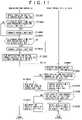
- FIG. 1illustrates a diagram showing the structure of a communication network system including the access relaying apparatus 2 according to the embodiment.
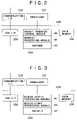
- FIG. 2illustrates a diagram showing the structure of the proxy server 23 - n forming the access relaying apparatus 2 .
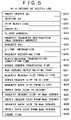
- FIG. 3illustrates a diagram showing the structure of the administration server 24 forming the access relaying apparatus 2 .
- FIG. 4illustrates a diagram showing the data structure of the access log file 50 stored in the disk device 25 according to the embodiment.
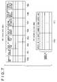
- FIG. 5illustrates a diagram showing one example of the data structure of the records of the access logs 61 - 1 to 60 -K as entities of the access log.
- FIG. 6illustrates a flowchart showing the processing for obtaining the contents of the proxy server 23 - n according to the embodiment.
- FIG. 7illustrates a diagram showing an example of the data structure of the statistic data table 70 and the access log file table 71 .
- FIG. 8illustrates a flowchart showing the access log statistic processing performed by the administration server 24 according to the embodiment.
- FIG. 9illustrates a diagram showing an example of the data structure of the 23 - n Web server access management table 80 and the request URL access management table 81 .
- FIG. 10illustrates a diagram showing an example of the data structure of the Web server access limit management table 90 and the request URL access limit management table 91 .
- FIG. 11illustrates a flowchart of the processing for updating the, access limit 902 and 912 in the administration server 24 and for updating the access limit 802 in the 23 - n Web server access management table 80 and the access limit 812 in the request URL access management table 81 according to the embodiment.
- FIG. 1shows the structure of a communication network system including an access relaying apparatus 2 according to the embodiment.
- the access relaying apparatus 2is connected to a plurality of client devices 1 ( 1 - 1 to 1 -L) via a communication network 11 such as a LAN or the Internet, and is further connected to a Web server 3 ( 3 - 1 to 3 -J) via a network (hereinafter referred to as the Internet) 12 such as the Internet.
- a communication network 11such as a LAN or the Internet
- a Web server 33 - 1 to 3 -J
- the Internet 12such as the Internet.
- the access relaying apparatus 2includes a router 21 which is connected to the communication network 11 and the Internet 12 , a load balancer 22 which is connected to the router 21 , a plurality of proxy servers 23 - n (1 ⁇ n ⁇ N) which are connected to the load balancer 22 , an administration server 24 having a communication function, with the plurality of proxy servers 23 , a shared disk device 25 which stores access logs outputted by the plurality of proxy servers 23 , and an SAN (Storage Area Network, that is, fast disk communication network) 26 which connects the proxy servers 23 , the administration server 24 , and the disk device 25 .
- the disk device 25stores statistic data formed by the administration server 24 . The details of the shared disk device 25 will be described later.
- the request for obtaining the contents sent from the client 1is received by the router 21 and then is transferred to the load balancer 22 .
- the load balancer 22sequentially load-balances the request for obtaining the contents received from the router 21 to the proxy servers 23 - n in accordance with a predetermined load balancing algorithm.
- the proxy server 23 - nsends the cached contents to the client 1 . If the contents are not included in (are not hit to) the cache memory, the proxy server 23 - n transmits the received request for obtaining the contents to an arbitrary Web server 3 -J for providing the contents.
- the Web server 3 -Jforms a reply message including the requested contents, and sends the formed reply message to the proxy server 23 - n which transmits the request for obtaining the contents.
- the proxy server 23 - n which receives the reply messagetransmits the received reply message to the client 1 as the transmission source of the request for obtaining the contents.
- the proxy server 23 - ntransmits the contents to the client 1 as the transmission source of the request for obtaining the contents when it can send the contents internally or externally stored in the cache memory as a reply to the received request for obtaining the contents.
- the proxy server 23 - nAfter that, the proxy server 23 - n outputs the access log as a communication record to the disk device 25 .
- the proxy server 23 - nreceives the request for obtaining the contents sent from the client 1 via the router 21 and the load balancer 22 . If the number of processed requests for obtaining the contents is over the access limit, the proxy server 23 - n forms an error message in response to the received request for obtaining the contents and transmits the formed error message to the client 1 as the transmission source of the request for obtaining the contents (the proxy server 23 - n does not transmit the request for obtaining the contents to the Web server 3 -J).
- FIG. 2is a diagram showing the structure of the proxy server 23 - n.
- the proxy server 23 - nincludes a processor 231 , a communication interface 232 for connection to the load balancer 22 and the administration server 24 , a disk input/output interface 233 for connection to the disk device 25 , and a memory 234 for program storage, and a memory 235 for data storage. These components are mutually connected via an internal communication line (hereinafter, referred to as a bus) 236 .
- the memory 234stores, as control software executed by the processor 231 , a packet transfer control module 40 for controlling the reception and transmission of a packet (message) transmitted to another device via the communication interface 232 , a request processing module 41 , and another control module 42 .
- FIG. 3is a diagram showing the structure of the administration server 24 .
- the administration server 24can be structured similarly to the proxy server 23 - n .
- the communication interface 232is used for connection to the load balancer 22 and the proxy server 23 - n .
- the memory 234stores, as control software executed by the processor 231 , an access statistic processing module 45 for reading the access log stored in the disk device 25 and for statistic processing, an access limit processing module 46 for determining the access limit to the Web server 3 - j based on the statistic processing result, and another control module 47 .
- FIG. 4is a diagram showing the data structure of a file for storing the access logs stored on the disk device 25 shared by the plurality of proxy servers.
- An access log file 50 for storing the access logsincludes an access log file header 60 for storing information on the access log file 50 and a record of the access log 61 - k (1 ⁇ k ⁇ K) as an entity of the access log which is outputted from the proxy server 23 .
- the access log file header 60includes a log output start time 601 indicating the date and time when the access log is first written, a log output end time 602 indicating the date and time when the access log is finally written, a next-access-log file name 603 indicating the changing destination when the proxy server changes the output destination of the access log to another file, and a number of records of the access log 604 indicating the number of the access logs stored in the file.
- the single access log file 50is assigned to each proxy server. Therefore, N access log files 50 - n (1 ⁇ n ⁇ N) for the proxy server 23 - n exist on the disk device 25 .
- FIG. 5is a diagram showing a data format of the single record of the access log 61 - k formed every session unit as the entity of the access log.
- the record of the access log 61 - kincludes: a proxy server number 610 for specifying the proxy server which outputs the record; a session number 611 as a reception number of the request for obtaining the contents received by the proxy server; an HTTP reply code 612 indicating an error status added to the reply message from the Web server; an error number 613 indicating an error code for the reply of the proxy server 23 to the client 1 ; a client address 614 for specifying the transmission source of the received request for obtaining the contents; a request transfer destination (Web server) address 615 indicating the transmission destination of the request for obtaining the contents; a request URL 616 indicating the destination for obtaining the contents described in the request for obtaining the contents; client information 617 indicating information on the client 1 which transmits the request for obtaining the contents; a request reception time 618 indicating the reception time of the request for obtaining the contents from the client 1 by the proxy server 23 - n ; a reply message transmission completion time 619 indicating the end time for transmitting the reply message to
- the sessionmeans one-time reception and transmission from the issue of any desired request on the access source (access relaying apparatus according to the embodiment) to the reply to the request on the access destination (service provider server according to the embodiment).
- FIG. 6is a flowchart of processing for the request for obtaining the contents of the proxy server 23 - n.
- the proxy server 23 - nreceives the request for obtaining the contents from the client 1 (S 1001 ) and then it is checked whether or not the request for obtaining the contents includes an error (S 1002 ). If the request for obtaining the contents includes the error, an error message is sent to the client 1 (S 1010 ). If the request for obtaining the contents does not include the error, it is checked whether or not the reply message corresponding to the request exists in the cache on the proxy server 23 - n (S 1011 ). If the reply message exists in the cache (is hit to the cache), the reply message is read and the reply message is formed (S 1012 ) and the formed reply message is sent to the client 1 .
- the request for obtaining the contents from the clientis sent to the Web server 3 - j which provides the contents (S 1003 ). Then, the return of the reply message from the Web server 3 - j is waited (S 1004 ). If the reply message is not returned from the Web server 3 - j and the time is out (S 1013 ), the error message is transmitted to the client 1 (S 1010 ). The reply message is received from the Web server 3 - j ( 1004 ), it is checked whether or not the reply message includes any error (S 1005 ). If the reply message includes an error, the error message is sent to the client 1 (S 1010 ).
- the proxy server 23 - nforms the access log record shown in FIG. 5 in accordance with the processing result (S 1007 ). Further, the proxy server 23 - n outputs the access log record to the access log file 50 in the disk device 25 (S 1008 ). The number of records of the access log 604 in the access log file header 60 is updated (S 1009 ).
- the disk device 25 as the output destination of the access logmay include two disks 252 - 1 and 252 - 2 , a disk control device 251 , a back-up device 253 , and a cache memory 254 .
- the disk control device 251having the structure shown in FIG. 1 writes the same data to the disks 252 - 1 and 252 - 2 and the cache memory.
- the disk device 251may have the structure other than that shown in FIG. 1 .
- the proxy server 23 - nstores the access logs collected by the proxy server 23 - n in the disk device 25 and thus the loss of the access log due to the default of the proxy server 23 - n is prevented and the back-up and collection are easy.
- the proxy server 23 - nis reduced in size without providing the disk for the proxy server 23 - n . Consequently, the access relaying apparatus 2 is structured with a saved space.
- FIG. 7shows an example of the structure of a table generated by the administration server 24 .
- a statistic data table 70stores statistic data obtained from the access log.
- the statistic data table 70includes a request URL 700 indicating the destination of the request for obtaining the contents transmitted by the clients 1 - 1 to 1 -L, a total of accesses 701 to the request URL, a total of a reply time 702 from the Web server 3 - j upon access to the request URL, an average reply time 703 , a total data size of the request 704 transmitted to the request URL, an average data size of the request 705 , a total data size of the reply message 706 of the reply message from the Web server 3 - j , and an average data size of the reply message 707 .
- the statistic data table 70is stored onto the disk device 25 .
- the access log file table 71includes N entries indicating the access log file 50 - n . Each entry includes an access log file name 710 as a reference target, and a number of read access logs 711 indicating the number of access logs which have already been processed by the administration server 24 .
- an initial setting file namemay previously be recorded to an initial setting file of the administration server 24 , and the contents of the initial setting file may be read and the access log file name may be set upon initializing the administration server 24 .
- a method for sending a notification to the administration server 24 by the proxy server 23 - nmay be used.
- FIG. 8is a flowchart showing the outline of the statistic processing of the administration server 24 .
- the administration server 24sets the access log file name 710 first entering the access log file table 71 as a reference access log file name (S 1101 ).
- the administration server 24reads the access log file header 60 of the reference access log file 50 on the disk device 25 (S 1102 ).
- the administration server 24checks whether or not the next access log file 603 is set (S 1103 ).
- the access log file name 710is replaced with the file name of the entry which is currently referred to on the access log file table 71 , and the number of the read access logs 711 is initialized to zero (S 1104 ).
- the reference access log fileis changed by the operations in steps S 1102 to S 1104 .
- the number of records of the access log 604 in the read access log file header 60is compared with the number of the read access logs 711 in the access log file table 71 (S 1105 ). When both the values are matched, all K log files included in the reference access log file are processed. Then, the processing routine shifts to processing for changing the reference access log file (S 1113 ).
- the number of records of the access log 604is larger than the number of the read access logs 711 , the records of the access log 61 - k to 61 -K which are not read from the access log file 50 subsequently to the number of the read access logs and, for example, the read records of the access log are stored in the data memory 235 (S 1106 ).
- the administration server 24checks cache flags 630 of all the read records of the access log. If the cache flags 630 indicate that the contents of the records do not use the cache (S 1107 ), the records of the access log in this case are subjected to the processing in steps S 1108 to S 1112 .
- the administration server 24searches for the entries in the statistic data table 70 by use of the request URL 616 of the record of the access log 61 - k as a search key (S 1108 ).
- the request URLs 616 in the record of the access log 61 - kpartly match the request URL 700 in the statistic data table 70 (ranging a head character of the URL to a prescribed portion) or when all the request URLs 616 match it (S 1109 )
- the contents of the matched entry in the statistic data table 70are changed based on the contents of the record of the access log 61 - k (S 1110 ).
- An optical settingis possible upon starting the system when the prescribed range is set or when the matching is checked by the method using the part or the method using all the request URLs.
- the resultmay be stored in the data memory 235 .
- the total of accesses 701is incremented by 1 and a value obtained by subtracting the request reception time 618 from the reply message transmission completion time 619 is added to the total reply time 702 .
- a value obtained by dividing the changed total reply time 702 by the changed total of accesses 701is set to the average reply time 703 .
- the header size of the request 626 to the Web server and the data size of the request 628 to the Web serverare added to the total data size of the request 704 .
- a value obtained by dividing the changed total data size of the request 704 by the total of accesses 701is set to the average data size of the request 705 .
- the header size of the reply 623 to the client and the data size of the reply 625 to the clientare added to the total data size of the reply message 706 .
- a value obtained by dividing the changed total data size of the reply message 706 by the total of accesses 701is set to the average data size of the reply message 707 .
- the data sizeis not directly used for the access control according to the embodiment.
- an operator of the administration server 24monitors a traffic to the service server and, for example, the data size can be used as the measure of equipment enhance.
- a new entry as the contents of the record of the access log 61 - kis added to the statistic data table 70 (S 1111 ).
- the request URL 616is set to the request URL 700 , one is set to the total of accesses, a value obtained by subtracting the request reception time 618 from the reply message transmission completion time 619 is set to the total reply time 702 .
- a value obtained by dividing the changed total reply time 702 by the changed total of accesses 701is set to the average reply time 703 .
- An addition value of the header size of the request 626 to the Web server and the data size of the request 628 to the Web serveris set to the total data size of the request 704 .
- a value obtained by dividing the changed total data size of the request 704 by the total of accesses 701is set to the average data size of the request 705 .
- An addition value of the header size of the reply 623 to the client and the data size of the reply 625 to the clientis set to the total data size of the reply message 706 .
- a value obtained by dividing the changed total data size of the reply message 706 by the total of accesses 701is set to the average data size of the reply message 707 .
- the value of the read access log 711is replaced with the value of records of the access log 604 (S 1112 ).
- the administration server 24changes the reference access log file.
- the administration server 24When the access log file which is currently referred to is the final file which enters the access log file table 71 (S 1113 ), the administration server 24 returns the reference access log file to the access log file which first enters the access log file table 71 (S 1114 ). If not so, the administration server 24 changes the reference access log file to the access log file described in the next entry which is currently referred to in the access log file table 71 (S 1115 ).
- the administration server 24returns to processing for reading the access log file header 60 (S 1102 ) whereupon the abovementioned processing is repeated.
- the proxy server 23 - ndoes not need to respond to the access log read from the administration server 24 and therefore a processing load is reduced. Further, the administration server 24 does not give the proxy server 23 - n the processing load. Therefore, the above operation can be repeated periodically at a short interval (for example, a second-order interval). Thus, since the statistic processing of the accesses relayed by the access relaying apparatus 2 can frequently be performed, the feed-back of the statistic processing result becomes effective.
- the administration server 24refers to the access log for a short time after the proxy server 23 - n writes the access log, a cache hit ratio of the access log written to the cache memory in the disk device 251 is high and the administration server 24 can read the access log for a short time. Further, back-up data of all the access logs is collected by collecting back up data of the disk 252 - 1 or 252 - 2 by the back-up device 253 .
- the cooperation of the proxy server 23 - n and the administration server 24enables the limitation to the access to the Web server 3 -J from the clients 1 - 1 to 1 -L.
- a function thereofwill be described.
- FIG. 9is a diagram showing the data structure of the access management table included in the proxy server 23 - n .
- the number of accesses to the Web server 3 -Jenables both the limitation to the access to the Web server and the limitation to the access at the request URL.
- the Web server access management table 80includes a Web server address 800 indicating the transmission destination Web server of the request for obtaining the contents from the clients 1 - 1 to 1 -L, a number of accesses 801 indicating the number of requests for obtaining the contents which are currently transmitted to the Web server, and an access limit 802 per unit time indicating an upper limit of transmissions of the requests for obtaining the contents which are simultaneously transmitted to the Web server.
- the request URL access management table 81includes a request URL 810 indicating a transmission destination URL of the request for obtaining the contents from the clients 1 - 1 to 1 -L, a number of accesses 811 indicating the number of requests for obtaining the contents which are currently transmitted to the request URL, and an access limit 812 per unit time indicating an upper limit of transmissions of the requests for obtaining the contents which are simultaneously transmitted to the request URL.
- FIG. 10is a diagram showing the data structure of an access limit number management table included in the administration server 24 . Similarly to the proxy server 23 - n , both an access limit number management table to the Web server and an access limit number management table to the request URL exist.
- a Web server access limit management table 90includes a Web server address 900 indicating the Web server as the transmission destination of the request for obtaining the contents from the clients 1 - 1 to 1 -L, an access limit prescribed value 901 as a reference for access limit, an average reply time 902 upon transmitting the request for obtaining the contents to the Web server obtained from the statistic data table 70 shown in FIG. 7 , and an access limit 903 per unit time indicating an upper limit of transmissions of the requests for obtaining the contents which are simultaneously transmitted to the Web server.
- a request URL access limit management table 91includes a request URL 910 indicating a transmission destination URL of the request for obtaining the contents from the clients 1 - 1 to 1 -L, an access limit prescribed value 911 as a reference for the access limit, an average reply time 912 upon transmitting the request for obtaining the contents to the request URL obtained from the statistic data table 70 shown in FIG. 7 , and an access limit 913 per unit time indicating an upper limit of transmissions of the requests for obtaining the contents which are simultaneously transmitted to the request URL.
- the two types of tablesenable the access limit for all the requests to a specific Web server and access limit for a specific URL (namely, service).
- FIG. 11is a flowchart indicating a method for updating the access limit between the administration server 24 and the proxy server 23 - n .
- the processing flowmay start upon updating the statistic data table 70 .
- the administration server 24Upon updating the statistic data table as the result of the access log statistic processing S 1100 in step S 1109 or S 1110 as shown in FIG. 8 , the administration server 24 sets a value of the average reply time 703 in the statistic data table 70 to the average reply time 902 in the Web server access limit management table 90 and the average reply time 912 in the request URL access limit management table 91 (S 1301 ). Thereafter, the average reply time 902 in the Web server access limit management table 90 is compared with the access limit prescribed value 901 (S 1302 ).
- the access limit 903is reduced by the prescribed value (approximately 1 to 10, determined by a communication scale of the access relaying apparatus 2 ), and the access limit 903 is updated (S 1303 ).
- the average reply time 912 in the request URL access limit management table 91is compared with the access limit prescribed value 911 (S 1304 ). If the average reply time 912 is over the prescribed value, the access limit 913 is decreased by the prescribed value and the access limit 913 is updated (S 1305 ).
- Information on the finally changed combination of the Web server address 900 and the access limit 903 and information on the combination of the request URL 910 and the access limit 913are notified to the proxy server 23 - n (S 1306 ).
- the notificationmay be sent via the SAN 26 or via the network connecting the load balancer 22 and the proxy server 23 - n.
- the proxy server 23 - nreceives the information on the access limit 903 and 913 from the administration server 24 (S 1401 ). Then, the proxy server 23 - n checks whether or not a target entry of the access limit 903 exists in the Web server access management table 80 (S 1402 ). If YES in step S 1402 , the access limit 802 of the entry is replaced to the notified access limit 903 (S 1403 ). If NO in step S 1402 , the new entry is added to the Web server access management table 80 by use of the notified Web server address 900 and access limit 903 (S 1404 ). Further, the proxy server 23 - n checks whether or not the target entry of the access limit 913 exists in the request URL access management table 81 (S 1405 ).
- step S 1405the access limit 812 of the entry is replaced to the notified access limit 913 (S 1406 ). If NO in step S 1405 , the new entry is added to the request URL access management table 81 by use of the notified request URL 910 and the access limit 913 (S 1407 ).
- the proxy server 23 - nforms an error message to the received request for obtaining the contents and sends it to the client 1 as the transmission source of the request for obtaining the contents.
- the proxy server 23 - nreflects the entire access statuses via the access relaying apparatus 2 to the access limit to the Web server in cooperation with the administration server 24 for a short time.
- the statistic processing in which the plurality of proxy servers 23 - n sum up the access statusesenables accurate access control.
- the access log as the communication recordis stored in the shared disk device. Consequently, not only the loss of the access log due to the default of the proxy server is prevented but also the back-up of the access log is easy.
- the access logmay be read from the shared disk device.
- the overhead of the collection of the access logs in the statistic processingis reduced.
- the access status to the Web server which is obtained from the result of the statistic processingis reflected to the control for the access to the proxy server for a short time in cooperation with the proxy server and the server for the statisitc processing. Further, the Web server is protected from the deterioration in service quality due to the access concentration to the specific Web server.
Landscapes
- Engineering & Computer Science (AREA)
- Signal Processing (AREA)
- Computer Networks & Wireless Communication (AREA)
- Mathematical Optimization (AREA)
- Probability & Statistics with Applications (AREA)
- Algebra (AREA)
- General Physics & Mathematics (AREA)
- Mathematical Analysis (AREA)
- Computer Security & Cryptography (AREA)
- Mathematical Physics (AREA)
- Physics & Mathematics (AREA)
- Pure & Applied Mathematics (AREA)
- Computer Hardware Design (AREA)
- General Engineering & Computer Science (AREA)
- Environmental & Geological Engineering (AREA)
- Information Transfer Between Computers (AREA)
- Computer And Data Communications (AREA)
- Information Retrieval, Db Structures And Fs Structures Therefor (AREA)
Abstract
Description
Claims (11)
Applications Claiming Priority (2)
| Application Number | Priority Date | Filing Date | Title |
|---|---|---|---|
| JP2002357412AJP4098610B2 (en) | 2002-12-10 | 2002-12-10 | Access relay device |
| JP2002-357412 | 2002-12-10 |
Publications (2)
| Publication Number | Publication Date |
|---|---|
| US20040111492A1 US20040111492A1 (en) | 2004-06-10 |
| US7558854B2true US7558854B2 (en) | 2009-07-07 |
Family
ID=32322068
Family Applications (1)
| Application Number | Title | Priority Date | Filing Date |
|---|---|---|---|
| US10/383,243Expired - Fee RelatedUS7558854B2 (en) | 2002-12-10 | 2003-03-07 | Access relaying apparatus |
Country Status (5)
| Country | Link |
|---|---|
| US (1) | US7558854B2 (en) |
| EP (1) | EP1429517B1 (en) |
| JP (1) | JP4098610B2 (en) |
| CN (1) | CN100496037C (en) |
| DE (1) | DE60313567T2 (en) |
Cited By (16)
| Publication number | Priority date | Publication date | Assignee | Title |
|---|---|---|---|---|
| US20070168317A1 (en)* | 2006-01-17 | 2007-07-19 | Fujitsu Limited | Log retrieving method, log administration apparatus, information processing apparatus and computer product |
| US20080140809A1 (en)* | 2006-12-07 | 2008-06-12 | Rock Won Kim | System and method for providing contents service using service relaying apparatus |
| US20080273600A1 (en)* | 2007-05-01 | 2008-11-06 | Samsung Electronics Co., Ltd. | Method and apparatus of wireless communication of uncompressed video having channel time blocks |
| US20090109938A1 (en)* | 2007-10-31 | 2009-04-30 | Samsung Electronics Co., Ltd. | Method and system for medium access control in communication networks |
| US20100293266A1 (en)* | 2009-05-12 | 2010-11-18 | Schilling Mark A | System and method for dynamic control of network management traffic loads |
| US20120331077A1 (en)* | 2006-12-28 | 2012-12-27 | Canon Kabushiki Kaisha | Information processing apparatus, method of controlling information processnig apparatus, program for control method, and recording medium for program |
| CN103209087A (en)* | 2012-01-17 | 2013-07-17 | 深圳市腾讯计算机系统有限公司 | Distributed log statistical processing method and system |
| US10419572B2 (en)* | 2013-08-06 | 2019-09-17 | Walmart Apollo, Llc | Caching system and method |
| US10803015B2 (en) | 2013-08-06 | 2020-10-13 | Walmart Apollo, Llc | Caching system and method |
| US20240314191A1 (en)* | 2009-10-08 | 2024-09-19 | Bright Data Ltd. | System providing faster and more efficient data communication |
| US12250089B2 (en) | 2017-08-28 | 2025-03-11 | Bright Data Ltd. | System and method for improving content fetching by selecting tunnel devices |
| US20250086140A1 (en)* | 2023-09-12 | 2025-03-13 | VMware LLC | Workload-responsive distributed segment cleaning |
| US12278878B2 (en) | 2013-08-28 | 2025-04-15 | Bright Data Ltd. | System and method for improving internet communication by using intermediate nodes |
| US12309123B2 (en) | 2019-04-02 | 2025-05-20 | Bright Data Ltd. | System and method for managing non-direct URL fetching service |
| US12332960B2 (en) | 2019-02-25 | 2025-06-17 | Bright Data Ltd. | System and method for URL fetching retry mechanism |
| US12445511B2 (en) | 2023-01-22 | 2025-10-14 | Bright Data Ltd. | System and method for streaming content from multiple servers |
Families Citing this family (31)
| Publication number | Priority date | Publication date | Assignee | Title |
|---|---|---|---|---|
| DE10345535B4 (en)* | 2003-09-30 | 2005-10-06 | Siemens Ag | Checking the availability of a server |
| DE10356724B3 (en)* | 2003-12-02 | 2005-06-16 | Deutsches Zentrum für Luft- und Raumfahrt e.V. | Method for reducing the transport volume of data in data networks |
| ES2297734T3 (en)* | 2004-07-22 | 2008-05-01 | Barefruit Limited | IMPROVED USER INTERFACE. |
| JP2007115140A (en)* | 2005-10-21 | 2007-05-10 | Hitachi Ltd | Storage system and storage system control method |
| CN100452720C (en)* | 2005-12-20 | 2009-01-14 | 英业达股份有限公司 | Information access amount statistical system and method |
| JP2007188189A (en)* | 2006-01-11 | 2007-07-26 | Sharp Corp | Portable terminal and control method thereof, data relay device and control method thereof, data providing system, portable terminal control program, and recording medium recording the program |
| US20080016196A1 (en)* | 2006-07-14 | 2008-01-17 | Anthology Solutions, Inc. | System and method for automatic storage and serving of digital content |
| US9124767B2 (en)* | 2006-10-25 | 2015-09-01 | Microsoft Technology Licensing, Llc | Multi-DVR media content arbitration |
| JP4956176B2 (en)* | 2006-12-21 | 2012-06-20 | キヤノン株式会社 | Monitoring host device, image forming apparatus, control method therefor, and program |
| CN101681340A (en)* | 2007-04-17 | 2010-03-24 | 肯尼思·托拉 | Non-intrusive method and system for collecting information transmitted over a network |
| CN100563365C (en)* | 2007-07-25 | 2009-11-25 | 华为技术有限公司 | A method and device for access event statistics |
| JP2009059160A (en)* | 2007-08-31 | 2009-03-19 | Sony Corp | Server device, network system, content discovery notification method and computer program |
| CN101127766B (en)* | 2007-09-24 | 2010-06-09 | 中兴通讯股份有限公司 | Message processing method, device and IP communication system based on SIP protocol |
| US20090164600A1 (en)* | 2007-12-19 | 2009-06-25 | Concert Technology Corporation | System and method for place-shifting media items |
| US8725740B2 (en) | 2008-03-24 | 2014-05-13 | Napo Enterprises, Llc | Active playlist having dynamic media item groups |
| US8811420B2 (en)* | 2009-01-05 | 2014-08-19 | Samsung Electronics Co., Ltd. | System and method for contention-based channel access for peer-to-peer connection in wireless networks |
| JP5061210B2 (en)* | 2009-08-25 | 2012-10-31 | ヤフー株式会社 | Application server and method for monitoring multiple backend servers |
| JP2011048784A (en)* | 2009-08-28 | 2011-03-10 | Canon Inc | Apparatus and method for forming image, and program |
| CN102075556B (en)* | 2009-11-19 | 2014-11-26 | 北京明朝万达科技有限公司 | Method for designing service architecture with large-scale loading capacity |
| JP2011221682A (en)* | 2010-04-07 | 2011-11-04 | Seiko Epson Corp | Information processor |
| US9854055B2 (en)* | 2011-02-28 | 2017-12-26 | Nokia Technologies Oy | Method and apparatus for providing proxy-based content discovery and delivery |
| JP5717589B2 (en)* | 2011-08-25 | 2015-05-13 | Kddi株式会社 | Content delivery control server, method and program |
| US8909808B2 (en)* | 2012-07-19 | 2014-12-09 | Cisco Technology, Inc. | Redundancy elimination for web caching |
| CN103401937B (en)* | 2013-08-07 | 2016-06-08 | 中国科学院信息工程研究所 | Daily record data processing method and system |
| JP2015122575A (en)* | 2013-12-20 | 2015-07-02 | 株式会社東芝 | Communication system and backup data management method |
| KR102333753B1 (en)* | 2014-12-26 | 2021-12-01 | 주식회사 케이티 | Method, server and system for providing contents |
| WO2016183545A1 (en) | 2015-05-14 | 2016-11-17 | Walleye Software, LLC | Distributed and optimized garbage collection of remote and exported table handle links to update propagation graph nodes |
| JP6608662B2 (en)* | 2015-10-01 | 2019-11-20 | 東芝テック株式会社 | Information providing apparatus and information providing program |
| US10484415B1 (en)* | 2016-12-16 | 2019-11-19 | Worldpay, Llc | Systems and methods for detecting security risks in network pages |
| US10198469B1 (en) | 2017-08-24 | 2019-02-05 | Deephaven Data Labs Llc | Computer data system data source refreshing using an update propagation graph having a merged join listener |
| US11194930B2 (en) | 2018-04-27 | 2021-12-07 | Datatrendz, Llc | Unobtrusive systems and methods for collecting, processing and securing information transmitted over a network |
Citations (17)
| Publication number | Priority date | Publication date | Assignee | Title |
|---|---|---|---|---|
| WO1998045978A2 (en) | 1997-04-09 | 1998-10-15 | Webtv Networks, Inc. | Method and apparatus for providing remote site administrators with user hits on mirrored web sites |
| EP0883271A2 (en) | 1997-04-15 | 1998-12-09 | Hewlett-Packard Company | Method and system for managing data service systems |
| JPH1125059A (en) | 1997-07-04 | 1999-01-29 | Nippon Telegr & Teleph Corp <Ntt> | Network library operating method and system, and storage medium storing network library operating program |
| US6018619A (en)* | 1996-05-24 | 2000-01-25 | Microsoft Corporation | Method, system and apparatus for client-side usage tracking of information server systems |
| US6070191A (en)* | 1997-10-17 | 2000-05-30 | Lucent Technologies Inc. | Data distribution techniques for load-balanced fault-tolerant web access |
| US6134588A (en)* | 1997-11-12 | 2000-10-17 | International Business Machines Corporation | High availability web browser access to servers |
| US6314465B1 (en)* | 1999-03-11 | 2001-11-06 | Lucent Technologies Inc. | Method and apparatus for load sharing on a wide area network |
| US6317787B1 (en) | 1998-08-11 | 2001-11-13 | Webtrends Corporation | System and method for analyzing web-server log files |
| JP2002082926A (en) | 2000-09-06 | 2002-03-22 | Nippon Telegr & Teleph Corp <Ntt> | Distributed application test and operation management system |
| US20020042828A1 (en)* | 2000-10-05 | 2002-04-11 | Christopher Peiffer | Connection management system and method |
| US6377975B1 (en)* | 2000-03-01 | 2002-04-23 | Interactive Intelligence, Inc. | Methods and systems to distribute client software tasks among a number of servers |
| US20020052942A1 (en)* | 2000-07-19 | 2002-05-02 | Swildens Eric Sven-Johan | Content delivery and global traffic management network system |
| US20020055980A1 (en) | 2000-11-03 | 2002-05-09 | Steve Goddard | Controlled server loading |
| US20030046398A1 (en)* | 2001-08-29 | 2003-03-06 | Charles Buckley | Method and system for managing a plurality of console devices in a network |
| US20050102427A1 (en)* | 2002-08-09 | 2005-05-12 | Daisuke Yokota | Stream contents distribution system and proxy server |
| US7047309B2 (en)* | 2000-08-23 | 2006-05-16 | International Business Machines Corporation | Load balancing and dynamic control of multiple data streams in a network |
| US7111061B2 (en)* | 2000-05-26 | 2006-09-19 | Akamai Technologies, Inc. | Global load balancing across mirrored data centers |
- 2002
- 2002-12-10JPJP2002357412Apatent/JP4098610B2/ennot_activeExpired - Fee Related
- 2003
- 2003-03-03EPEP03004681Apatent/EP1429517B1/ennot_activeExpired - Lifetime
- 2003-03-03DEDE60313567Tpatent/DE60313567T2/ennot_activeExpired - Lifetime
- 2003-03-07USUS10/383,243patent/US7558854B2/ennot_activeExpired - Fee Related
- 2003-10-31CNCNB2003101047030Apatent/CN100496037C/ennot_activeExpired - Fee Related
Patent Citations (18)
| Publication number | Priority date | Publication date | Assignee | Title |
|---|---|---|---|---|
| US6018619A (en)* | 1996-05-24 | 2000-01-25 | Microsoft Corporation | Method, system and apparatus for client-side usage tracking of information server systems |
| WO1998045978A2 (en) | 1997-04-09 | 1998-10-15 | Webtv Networks, Inc. | Method and apparatus for providing remote site administrators with user hits on mirrored web sites |
| JP2001519067A (en) | 1997-04-09 | 2001-10-16 | ウェブティーヴィー・ネットワークス・インコーポレーテッド | Method and apparatus for providing a user hit for a mirrored web site to a remote site operator |
| EP0883271A2 (en) | 1997-04-15 | 1998-12-09 | Hewlett-Packard Company | Method and system for managing data service systems |
| JPH1125059A (en) | 1997-07-04 | 1999-01-29 | Nippon Telegr & Teleph Corp <Ntt> | Network library operating method and system, and storage medium storing network library operating program |
| US6070191A (en)* | 1997-10-17 | 2000-05-30 | Lucent Technologies Inc. | Data distribution techniques for load-balanced fault-tolerant web access |
| US6134588A (en)* | 1997-11-12 | 2000-10-17 | International Business Machines Corporation | High availability web browser access to servers |
| US6317787B1 (en) | 1998-08-11 | 2001-11-13 | Webtrends Corporation | System and method for analyzing web-server log files |
| US6314465B1 (en)* | 1999-03-11 | 2001-11-06 | Lucent Technologies Inc. | Method and apparatus for load sharing on a wide area network |
| US6377975B1 (en)* | 2000-03-01 | 2002-04-23 | Interactive Intelligence, Inc. | Methods and systems to distribute client software tasks among a number of servers |
| US7111061B2 (en)* | 2000-05-26 | 2006-09-19 | Akamai Technologies, Inc. | Global load balancing across mirrored data centers |
| US20020052942A1 (en)* | 2000-07-19 | 2002-05-02 | Swildens Eric Sven-Johan | Content delivery and global traffic management network system |
| US7047309B2 (en)* | 2000-08-23 | 2006-05-16 | International Business Machines Corporation | Load balancing and dynamic control of multiple data streams in a network |
| JP2002082926A (en) | 2000-09-06 | 2002-03-22 | Nippon Telegr & Teleph Corp <Ntt> | Distributed application test and operation management system |
| US20020042828A1 (en)* | 2000-10-05 | 2002-04-11 | Christopher Peiffer | Connection management system and method |
| US20020055980A1 (en) | 2000-11-03 | 2002-05-09 | Steve Goddard | Controlled server loading |
| US20030046398A1 (en)* | 2001-08-29 | 2003-03-06 | Charles Buckley | Method and system for managing a plurality of console devices in a network |
| US20050102427A1 (en)* | 2002-08-09 | 2005-05-12 | Daisuke Yokota | Stream contents distribution system and proxy server |
Non-Patent Citations (2)
| Title |
|---|
| Japanese Office Action, issued in Japanese Patent Application No. JP 2002-357412, dated on Jul. 13, 2007. |
| Norifume Nishikawa, et al., "Memory-Based Architecture for Distributed WWW Caching Proxy", Computer Networks and ISDN Systems 30 (1998) 205-214. |
Cited By (39)
| Publication number | Priority date | Publication date | Assignee | Title |
|---|---|---|---|---|
| US7792803B2 (en)* | 2006-01-17 | 2010-09-07 | Fujitsu Limited | Log retrieving method, log administration apparatus, information processing apparatus and computer product |
| US20070168317A1 (en)* | 2006-01-17 | 2007-07-19 | Fujitsu Limited | Log retrieving method, log administration apparatus, information processing apparatus and computer product |
| US20080140809A1 (en)* | 2006-12-07 | 2008-06-12 | Rock Won Kim | System and method for providing contents service using service relaying apparatus |
| US7853694B2 (en)* | 2006-12-07 | 2010-12-14 | Electronics And Telecommunications Research Institute | System and method for providing contents service using service relaying apparatus |
| US20120331077A1 (en)* | 2006-12-28 | 2012-12-27 | Canon Kabushiki Kaisha | Information processing apparatus, method of controlling information processnig apparatus, program for control method, and recording medium for program |
| US9197447B2 (en)* | 2006-12-28 | 2015-11-24 | Canon Kabushiki Kaisha | Information processing apparatus, method of controlling information processing apparatus, program for control method, and recording medium for program |
| US20080273600A1 (en)* | 2007-05-01 | 2008-11-06 | Samsung Electronics Co., Ltd. | Method and apparatus of wireless communication of uncompressed video having channel time blocks |
| US8837435B2 (en) | 2007-10-31 | 2014-09-16 | Samsung Electronics Co., Ltd. | Method and system for medium access control in communication networks |
| US20090109938A1 (en)* | 2007-10-31 | 2009-04-30 | Samsung Electronics Co., Ltd. | Method and system for medium access control in communication networks |
| US20100293266A1 (en)* | 2009-05-12 | 2010-11-18 | Schilling Mark A | System and method for dynamic control of network management traffic loads |
| US8631109B2 (en)* | 2009-05-12 | 2014-01-14 | Hewlett-Packard Development Company, L.P. | System and method for dynamic control of network management traffic loads |
| US20240314191A1 (en)* | 2009-10-08 | 2024-09-19 | Bright Data Ltd. | System providing faster and more efficient data communication |
| US12323287B2 (en) | 2009-10-08 | 2025-06-03 | Bright Data Ltd. | System providing faster and more efficient data communication |
| US12284069B2 (en) | 2009-10-08 | 2025-04-22 | Bright Data Ltd. | System providing faster and more efficient data communication |
| US12301401B2 (en)* | 2009-10-08 | 2025-05-13 | Bright Data Ltd. | System providing faster and more efficient data communication |
| US12294481B2 (en) | 2009-10-08 | 2025-05-06 | Bright Data Ltd. | System providing faster and more efficient data communication |
| CN103209087A (en)* | 2012-01-17 | 2013-07-17 | 深圳市腾讯计算机系统有限公司 | Distributed log statistical processing method and system |
| CN103209087B (en)* | 2012-01-17 | 2015-12-16 | 深圳市腾讯计算机系统有限公司 | Distributed information log statistical processing methods and system |
| US10419572B2 (en)* | 2013-08-06 | 2019-09-17 | Walmart Apollo, Llc | Caching system and method |
| US10803015B2 (en) | 2013-08-06 | 2020-10-13 | Walmart Apollo, Llc | Caching system and method |
| US12323500B2 (en) | 2013-08-28 | 2025-06-03 | Bright Data Ltd. | System and method for improving internet communication by using intermediate nodes |
| US12341860B2 (en) | 2013-08-28 | 2025-06-24 | Bright Data Ltd. | System and method for improving internet communication by using intermediate nodes |
| US12278878B2 (en) | 2013-08-28 | 2025-04-15 | Bright Data Ltd. | System and method for improving internet communication by using intermediate nodes |
| US12438956B2 (en) | 2013-08-28 | 2025-10-07 | Bright Data Ltd. | System and method for improving internet communication by using intermediate nodes |
| US12309241B2 (en) | 2013-08-28 | 2025-05-20 | Bright Data Ltd. | System and method for improving internet communication by using intermediate nodes |
| US12425492B2 (en) | 2013-08-28 | 2025-09-23 | Bright Data Ltd. | System and method for improving internet communication by using intermediate nodes |
| US12323501B2 (en) | 2013-08-28 | 2025-06-03 | Bright Data Ltd. | System and method for improving internet communication by using intermediate nodes |
| US12375582B2 (en) | 2013-08-28 | 2025-07-29 | Bright Data Ltd. | System and method for improving internet communication by using intermediate nodes |
| US12368789B2 (en) | 2013-08-28 | 2025-07-22 | Bright Data Ltd. | System and method for improving internet communication by using intermediate nodes |
| US12289383B2 (en) | 2013-08-28 | 2025-04-29 | Bright Data Ltd. | System and method for improving internet communication by using intermediate nodes |
| US12413648B2 (en) | 2013-08-28 | 2025-09-09 | Bright Data Ltd. | System and method for improving internet communication by using intermediate nodes |
| US12355855B2 (en) | 2013-08-28 | 2025-07-08 | Bright Data Ltd. | System and method for improving internet communication by using intermediate nodes |
| US12250089B2 (en) | 2017-08-28 | 2025-03-11 | Bright Data Ltd. | System and method for improving content fetching by selecting tunnel devices |
| US12250090B2 (en) | 2017-08-28 | 2025-03-11 | Bright Data Ltd. | System and method for improving content fetching by selecting tunnel devices |
| US12332960B2 (en) | 2019-02-25 | 2025-06-17 | Bright Data Ltd. | System and method for URL fetching retry mechanism |
| US12411902B2 (en) | 2019-02-25 | 2025-09-09 | Bright Data Ltd. | System and method for URL fetching retry mechanism |
| US12309123B2 (en) | 2019-04-02 | 2025-05-20 | Bright Data Ltd. | System and method for managing non-direct URL fetching service |
| US12445511B2 (en) | 2023-01-22 | 2025-10-14 | Bright Data Ltd. | System and method for streaming content from multiple servers |
| US20250086140A1 (en)* | 2023-09-12 | 2025-03-13 | VMware LLC | Workload-responsive distributed segment cleaning |
Also Published As
| Publication number | Publication date |
|---|---|
| DE60313567T2 (en) | 2008-01-03 |
| CN1507235A (en) | 2004-06-23 |
| CN100496037C (en) | 2009-06-03 |
| US20040111492A1 (en) | 2004-06-10 |
| EP1429517A1 (en) | 2004-06-16 |
| DE60313567D1 (en) | 2007-06-14 |
| JP4098610B2 (en) | 2008-06-11 |
| EP1429517B1 (en) | 2007-05-02 |
| JP2004192170A (en) | 2004-07-08 |
Similar Documents
| Publication | Publication Date | Title |
|---|---|---|
| US7558854B2 (en) | Access relaying apparatus | |
| US11194719B2 (en) | Cache optimization | |
| US10880390B2 (en) | Method and apparatus for reducing network resource transmission size using delta compression | |
| US9608957B2 (en) | Request routing using network computing components | |
| US8024484B2 (en) | Caching signatures | |
| US8639817B2 (en) | Content management | |
| US9998533B2 (en) | P2P content caching system and method | |
| US20080235326A1 (en) | Methods and Apparatus for Accelerating Web Browser Caching | |
| JP4755683B2 (en) | Method, apparatus, and program for efficiently extending a peer-to-peer (P2P) network | |
| KR20090094292A (en) | Method, device and system for distributing file data | |
| RU2483457C2 (en) | Message routing platform | |
| CN114268631B (en) | Low-delay network system, communication connection method thereof and readable storage medium | |
| CN120066400A (en) | Front-end and rear-end fused thermal data multi-stage braking caching method and device | |
| JP3943868B2 (en) | Server-side proxy, data transfer method and program | |
| JP2006172296A (en) | Cache deletion method and content relay server | |
| JP2003242018A (en) | Cache method and cache server | |
| JP2003108462A (en) | Data transfer device and data transfer method | |
| JPH10322396A (en) | Transmission information relay server, transmission information relay method and system | |
| JP2002024191A (en) | Www system, traffic relief method for www server and www server |
Legal Events
| Date | Code | Title | Description |
|---|---|---|---|
| AS | Assignment | Owner name:HITACHI, LTD., JAPAN Free format text:ASSIGNMENT OF ASSIGNORS INTEREST;ASSIGNORS:NAKAHARA, MASAHIKO;NODA, FUMIO;REEL/FRAME:014323/0200;SIGNING DATES FROM 20030417 TO 20030418 | |
| AS | Assignment | Owner name:HITACHI, LTD., JAPAN Free format text:CORRECTION OF TYPING ERROR IN ASSIGNEE'S ADDRESS, RECORDED AT REEL 014323, FRAME 0200;ASSIGNORS:NAKAHARA, MASAHIKO;NODA, FUMIO;REEL/FRAME:015959/0876;SIGNING DATES FROM 20030417 TO 20030418 | |
| FEPP | Fee payment procedure | Free format text:PAYOR NUMBER ASSIGNED (ORIGINAL EVENT CODE: ASPN); ENTITY STATUS OF PATENT OWNER: LARGE ENTITY | |
| FPAY | Fee payment | Year of fee payment:4 | |
| AS | Assignment | Owner name:GOOGLE INC., CALIFORNIA Free format text:ASSIGNMENT OF ASSIGNORS INTEREST;ASSIGNOR:HITACHI, LTD.;REEL/FRAME:030555/0554 Effective date:20121016 | |
| REMI | Maintenance fee reminder mailed | ||
| LAPS | Lapse for failure to pay maintenance fees | ||
| STCH | Information on status: patent discontinuation | Free format text:PATENT EXPIRED DUE TO NONPAYMENT OF MAINTENANCE FEES UNDER 37 CFR 1.362 | |
| FP | Lapsed due to failure to pay maintenance fee | Effective date:20170707 | |
| AS | Assignment | Owner name:GOOGLE LLC, CALIFORNIA Free format text:CHANGE OF NAME;ASSIGNOR:GOOGLE INC.;REEL/FRAME:044142/0357 Effective date:20170929 |