US7558212B2 - System and method for fault identification - Google Patents
System and method for fault identificationDownload PDFInfo
- Publication number
- US7558212B2 US7558212B2US11/002,305US230504AUS7558212B2US 7558212 B2US7558212 B2US 7558212B2US 230504 AUS230504 AUS 230504AUS 7558212 B2US7558212 B2US 7558212B2
- Authority
- US
- United States
- Prior art keywords
- pathway
- along
- test
- fault
- response signal
- Prior art date
- Legal status (The legal status is an assumption and is not a legal conclusion. Google has not performed a legal analysis and makes no representation as to the accuracy of the status listed.)
- Active - Reinstated, expires
Links
- 238000000034methodMethods0.000titleclaimsabstractdescription39
- 238000012360testing methodMethods0.000claimsabstractdescription109
- 230000037361pathwayEffects0.000claimsabstractdescription63
- 230000004044responseEffects0.000claimsabstractdescription39
- 238000002310reflectometryMethods0.000claimsabstractdescription5
- RYGMFSIKBFXOCR-UHFFFAOYSA-NCopperChemical compound[Cu]RYGMFSIKBFXOCR-UHFFFAOYSA-N0.000claimsdescription7
- 229910052802copperInorganic materials0.000claimsdescription7
- 239000010949copperSubstances0.000claimsdescription7
- 239000000835fiberSubstances0.000claimsdescription7
- 230000005540biological transmissionEffects0.000claimsdescription5
- 230000003287optical effectEffects0.000claimsdescription5
- 238000005516engineering processMethods0.000description5
- 238000004458analytical methodMethods0.000description4
- 230000008439repair processEffects0.000description4
- 238000004891communicationMethods0.000description2
- 230000000295complement effectEffects0.000description2
- 239000004519greaseSubstances0.000description2
- 230000004075alterationEffects0.000description1
- 238000012512characterization methodMethods0.000description1
- 230000002452interceptive effectEffects0.000description1
- 238000005259measurementMethods0.000description1
- 239000002184metalSubstances0.000description1
- 229910052751metalInorganic materials0.000description1
- 238000012986modificationMethods0.000description1
- 230000004048modificationEffects0.000description1
- 239000013307optical fiberSubstances0.000description1
- 238000012552reviewMethods0.000description1
Images


Classifications
- H—ELECTRICITY
- H04—ELECTRIC COMMUNICATION TECHNIQUE
- H04L—TRANSMISSION OF DIGITAL INFORMATION, e.g. TELEGRAPHIC COMMUNICATION
- H04L41/00—Arrangements for maintenance, administration or management of data switching networks, e.g. of packet switching networks
- H04L41/06—Management of faults, events, alarms or notifications
- H04L41/0677—Localisation of faults
- H—ELECTRICITY
- H04—ELECTRIC COMMUNICATION TECHNIQUE
- H04L—TRANSMISSION OF DIGITAL INFORMATION, e.g. TELEGRAPHIC COMMUNICATION
- H04L41/00—Arrangements for maintenance, administration or management of data switching networks, e.g. of packet switching networks
- H04L41/12—Discovery or management of network topologies
- H—ELECTRICITY
- H04—ELECTRIC COMMUNICATION TECHNIQUE
- H04L—TRANSMISSION OF DIGITAL INFORMATION, e.g. TELEGRAPHIC COMMUNICATION
- H04L43/00—Arrangements for monitoring or testing data switching networks
- H04L43/50—Testing arrangements
Definitions
- the present inventionrelates generally to telecommunications and more particularly relates to a system and method for fault identification.
- Telecommunicationshas advanced such that there is now a vast array of services and technologies available to consumers. As services become more sophisticated, and competition more widespread, there is a natural pressure to reduce costs and improve efficiencies in the administration of a telecommunication network.
- test headsalong the path between the central office and the customer sites.
- test headscan be based on a variety of technologies, and are intended to look perform discrete metal readings along a designated pathway, with a view to identifying ground shorts, crosses and the like.
- DSLdigital subscriber line
- the digital subscriber line access module(“DSLAM”) is typically located intermediate legacy test heads and the subscriber sites, such that the DSLAM effectively filters out the signal generated by the test head and therefore interfering with the ability of the test head to provide meaningful fault identification.
- Legacy test heads located inside central officesare further hampered by the sheer complexity of the circuitry in the central office, as the central office itself effectively filters out signals generated by the test head.
- TDRTime Domain Reflectometer
- a method for identifying a fault along a linkcomprising the steps of:
- the response signalcan comprise a distance from a point where said test signal was generated to said fault.
- the location informationcan be stored in a geographic information system database.
- the linkcan be a copper twisted pair that spans an outside plant interface and a subscriber premises.
- the linkcan be less than or equal to about five thousand meters in length.
- the linkcan be less than or equal to about three thousand meters in length.
- the linkcan be less than or equal to about one thousand meters in length.
- the test signalcan be generated by a test head mounted in the outside plant interface. The test head can be remotely activatable in order to generate the test signal.
- the comparing step of the methodcan comprise the steps of determining a physical length along the link where the fault is potentially occurring and matching the physical length with information derived from a database representing a known physical location along the link corresponding to the length.
- the known physical locationcan include a set of geographic coordinates.
- the geographic coordinatescan be derived from the global positioning system (“GPS”) and the method can further comprise the step of delivering the coordinates to a client device accessible to a service technician to be deployed for repairing the fault.
- GPSglobal positioning system
- the linkcan also be coaxial cable, or a fibre optical cable, or an electrical transmission line.
- Another aspect of the inventionprovides a system for identifying a fault along a link comprising a test head for sending a test signal along the link.
- the testis also for receiving a response signal corresponding to the test signal.
- the systemalso includes a computing device for receiving the response signal from the test head.
- the computing deviceis operable to access a storage device connected to the computing device.
- the storage deviceis for storing location information corresponding to the link.
- the computing deviceis further operable to receive location information from the storage device and perform a comparison between the response signal and the location information to generate at least one potential physical location of the fault.
- the computing devicefor identifying a fault along a link.
- the computing deviceis connectable to a test head.
- the test headis operable to send a test signal along the link.
- the test headis further operable to receive a response signal corresponding to the test signal and deliver the response signal to the computing device.
- the computing deviceis further operable to access a storage device connectable to the computing device for storing location information corresponding to the link.
- the computing deviceis further operable to receive location information from the storage device and perform a comparison between the response signal and the location information to generate at least one potential physical location of the fault.
- Another aspect of the inventionprovides a computer readable medium containing a plurality of programming instructions for a computing device for identifying a fault along a link, the programming instructions including the steps of:
- Another aspect of the inventionprovides a method for identifying fault along a pathway comprising the steps of:
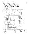
- FIG. 1is a schematic representation of a system for fault identification in accordance with an embodiment of the invention
- FIG. 2is a flowchart depicting a method of fault identification in accordance with another embodiment of the invention.
- FIG. 3shows the system of FIG. 1 during the performance of one of the steps of the method in FIG. 2 ;
- FIG. 4shows the system of FIG. 1 during the performance of one of the steps of the method in FIG. 2 ;
- FIG. 5shows the system of FIG. 1 during the performance of one of the steps of the method in FIG. 2 ;
- FIG. 6shows the system of FIG. 1 during the performance of one of the steps of the method in FIG. 2 ;
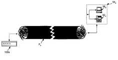
- FIG. 7shows a test head and a subscriber premises connected via a fibre optic cable in accordance with another embodiment of the invention.
- FIG. 8shows a test head and a subscriber premises connected via a coaxial cable in accordance with another embodiment of the invention.
- system 50is built upon the plain old telephone system (“POTS”) and thus comprises a plurality of subscriber sites 54 1 , 54 2 . . . 54 n (generically referred to herein as subscriber site 54 , and collectively as subscriber sites 54 ).
- Each subscriber site 54in turn includes a computing device 58 and a telephony device 62 .
- a service provider 66allows computing devices 58 to connect to the Internet 70 , and allows telephony devices 62 to connect to the public switched telephone network (“PSTN”) 74 .
- PSTNpublic switched telephone network
- service provider 66includes a central office switch 78 which carries calls from telephony devices 62 over PSTN 74 .
- switch 78connects to an outside plant interface 82 (“OPI”) via a feeder 86 .
- feeder 86comprises a plurality of manholes 90 , but it is to be understood in general that feeder 86 comprises any combination of cabling, bridges, junctions etc. that would normally be found between central office switch 78 and OPI 82 .
- OPI 82comprises a junction panel 94 , a DSLAM 98 .
- An exemplary DSLAMis the Stinger® Compact Remote from Lucent Technologies, 600 Mountain Ave, Murray Hill, N.J. 07974-0636, but other DSLAMs can be used.
- OPI 82also includes a test head 102 .
- Junction panel 94is used to couple twisted pairs arriving from feeder 86 with corresponding twisted pairs destined for subscriber sites 54 so that calls can be carried between telephony devices 62 and PSTN 74 .
- DSLAM 98joins Internet 70 with twisted pairs destined for subscriber sites 54 so that data connections can be carried between computing devices 58 and Internet 70 .
- Test head 102which in a present embodiment is based on TDR technology, can be used to test for faults along twisted pairs destined for subscriber sites 54 .
- An example of a TDR test head that can be usedis a CableSHARKTM from Consultronics Limited, 160 Drumlin Circle, Concord, Ontario, Canada, L4K 3E5, that is modified to complement the other features of the present embodiment, but other test heads can be used as desired.
- OPI 82is typically located on a street or other outdoor location and is within a predefined range of each subscriber sites 54 such that a given service level (i.e. bit rate) can be guaranteed for a particular computing device 58 accessing Internet 70 via DSLAM 98 .
- OPI 82is within about one thousand meters of all subscriber sites 54 . In other embodiments, OPI 82 is within about five thousand meters of all subscriber sites 54 , and in still other embodiments OPI 82 is within about three thousand meters of all subscriber sites 82 . In general such distances can be varied according to the performance characteristics of the particular DSLAM 98 and/or test head 102 that is being employed. Accordingly, it should now be apparent that system 50 is scalable. For example, a central office such as central office 78 can service a plurality of OPIs and in turn service a plurality of subscriber sites. System 50 can also include a plurality of central offices, each serving a plurality of OPIs.
- System 50also includes a customer care workstation 106 that is operated by a customer service representative associated with service provider 66 .
- Workstation 106in turn is connected to a management and diagnostics system 110 , which in a present embodiment is based on the Access Care Operating Support Systems (“OSS”) from Nortel Networks, 8200 Dixie Road, Brampton, Ontario L6T 5P6 Canada.
- OSSAccess Care Operating Support Systems
- a customer service representative operating workstation 106is thus able to receive calls from subscribers for each site 54 and to provide the usual management and diagnostic support as is currently offered by a system such as system 110 .
- system 110is also connected to a database 114 that includes information about the twisted pairs running between OPI 82 and subscriber sites 54 .
- the information in database 114is geographic information that can be coordinated and/or matched with TDR signals for a given pathway.
- system 110is also operable to access database 114 , and communicate with test head 102 , in order to identify faults in twisted pairs running between OPI 82 and sites 54 .
- pathways 118can be characterized by cable bundles of twisted pairs, each bundle being based on different cable designs. Pathways 118 can also be characterized by junctions, bridge points, splice points, wire locations, etc. As can be seen on FIG. 1 , in system 50 pathways 118 include a plurality of paths P and junctions J. Such characterizations are stored as information in database 114 . Table I shows an exemplary format of such information, that corresponds with the specific pathways 118 shown in FIG. 1 .
- Field 1“Site” identifies the particular sites 54 associated with the cable information in the same row.
- Field 2“Path” identifies the particular path corresponding with the respective path P that is shown in FIG. 2 , along which the cable in question runs.
- Field 3“Begin Point”, identifies where the particular cable begins its run—or in other words where the path P of the respective cable bundle begins.
- Field 4“Cable Identifier”, identifies a unique number associated with the particular cable that runs along the respective path, where each cable itself contains a bundle of twisted pairs. In the present example, for reasons of simplicity, there is only one unique cable identifier per path P.
- Field 5“Twisted Pair Identifier” identifies the particular twisted pair within the corresponding cable.
- Field 6“Cable Type”, provides mechanical and/or other specifications about the cable. In the example in table I, Cable Type is limited to type “A” and type “B”. However, Cable Type can include information such as gauge, number of twisted pairs within the cable bundle, how the cable is designed (i.e. grease filled, air filled, etc.) and/or any other desired information.
- Field 7“End Point”, identifies where the particular cable ends its run—or in other words where the path P respective to that cable bundle ends.
- Field 8“Length”, identifies the length of the particular path P respective to that cable bundle.
- a map or address of a physical location of each particular OSI, junction or siteis also stored in database 114 , so that a service technician can immediately locate the OSI, junction or site and be dispatched thereto with relative ease.
- a map that shows each individual path Pis also stored in database 114 , so that a service technician can readily trace the route of a particular P to reduce the amount of time that the technician need spend tracing the cable along that path P.
- the other information in Table Ican thus be used by a service technician to identify which particular cables and twisted pairs within those cables belong to a specific site 54 for a particular path P or junction J.
- a method for fault identificationin accordance with another embodiment of the invention, is indicated generally at 200 .
- method 200is operated using system 50 .
- system 50 and/or method 200can be varied, and need not work exactly as discussed herein in conjunction with each other, and that such variations are within the scope of the present invention.
- an identity of a subscriber site with a reported problemis received.
- this stepwill occur when a subscriber at a particular site 54 has difficulty with either voice or data services, and contacts a customer service representative at workstation 106 to notify service provider 66 of the problem.
- the subscriber at site 54 2is experiencing difficulties with data services (i.e. computing device 58 2 is having difficulty communicating over Internet 70 ), and thus contacts the customer service representative at workstation 106 to notify service provider 66 of the problem.
- This stepis represented in FIG. 3 by the dotted line indicated at “A”, which represents a telephone call between telephony device 62 2 and workstation 106 .
- line A and the subsequent lines indicated by letter charactersare intended to denote communications between particular components in system 50 , and are not intended, unless so indicated, to denote the actual pathway over which such communications occur).
- Method 200then advances to step 215 , at which point a test head is activated along the subscriber site's pathway.
- the customer service representative at workstation 106will enter an instruction into workstation 106 to remotely activate test head 102 to cause test head 102 to test the integrity of the path(s) P from OPI 82 to site 54 2 .
- This stepis represented in FIG. 4 by the dotted line indicated at “B”, which represents an instruction from workstation 106 to test head 102 to commence a test along the pathways P belonging to subscriber site 54 2 .
- Method 200then advances to step 220 , at which point a test signal is generated.
- test head 102will generate a waveform along the paths P corresponding to site 54 .
- This signalis represented in FIG. 5 by the dotted line indicated at “C”, which represents a test signal in the form of a waveform being generated by test head 102 .
- Method 200then advances to step 225 , at which point a response to the test signal is received.
- test head 102will receive a reflection of signal C generated at step 220 .
- This reflectionis represented in FIG. 6 by the dotted line indicated at “D”.
- signal Cwas reflected once signal C reached junction J 1 , to indicate that a fault exists at junction J 1 , but it is to be understood that the signal C and reflection could occur anywhere along the paths P from OPI 82 to site 54 depending on where, and whether, there were any faults along that paths P.
- Reflection Dthus originates at junction J 1 and is returned to test head 102 .
- test head 102assembles the data representing signal C and reflection D, and sends that data to system 110 for further analysis.
- step 230location information for the cabling for the relevant subscriber site is received.
- this stepis performed by system 110 , which loads cable information, such as the cable information stored in Table I, into system 110 from database 114 .
- the test signal from step 225is matched with the location information from step 235 .
- the way in which the particular matching is performedis not particularly limited, and a variety of operations can be conceived of which make use of the signal, waveform or other data from test head 102 and match it with cable information such as the cable information from Table I.
- the present examplehelps illustrate. Recall it was assumed that reflection D originated at junction J 1 . Using known TDR technology, an analysis of reflection D indicates, for example, that reflection D commenced about three-hundred meters, from test head 102 . By the same token, a review of Rows three through five (i.e.
- Table Iindicates that junction J 1 is located about three-hundred meters from OPI 82 . Since three-hundred meters corresponds with the TDR measurement, a match is made between the location of the fault identified by test head 102 and the location of where that fault likely occurred based on analysis of Table I.
- step 240a determination is made as to where the fault is located. Since at step 230 a match was found in Table I suggesting that the fault is located at junction J 1 the determination at this step would arise directly from the match made at step 235 .
- an output of the list of expected problem locationsis generated.
- This stepis performed by system 110 , which can generate a specific report that identifies that a fault is expected to be found at junction J 1 .
- This reportcan then be used to generate a work order that specifically instructs the service technician to attend at junction J 1 to repair the problem.
- This work ordercan thus reduce the amount of time, as the technician need not try to trace the entire set of paths P between OPI 82 and site 54 2 to find the fault, but can be dispatched directly to a location where the fault is expected to lie.
- the listcan include a primary location where potential problem is expected, and then a list of one or more additional, potential secondary fault locations to either side of primary location.
- steps 235 and 240are not particularly limited. Operations based on cable type and cable length can be tailored to help further improve the likelihood of specifically identifying a particular fault, and/or location thereof. For example, certain types of waveform reflections may be expected for cables having a particular number of bundles of twisted pairs contained therein, and/or whether or not the cable is air-filled, grease filled etc. Those expected types of waveforms can be compared with actually received waveform reflections to help further identify a particular fault and/or location thereof.
- TDRsent along a copper twisted pair
- other types of testingcan be performed.
- a combination of TDR and frequency domain reflectometrycan also be used.
- Other types of testingcan be performed that are complementary to the type of cabling used.
- optical TDRcan be used. This example is shown in FIG. 7 , wherein a fibre optic test head is indicated at 102 a , and is connected to a subscriber premises 54 a via a fibre optic cable P a . While not shown in FIG.
- system 50can be modified to accommodate fibre optic cable P a in order to provide a link between subscriber premises 54 a and the Internet 70 and/or the PSTN 74 and/or any other type of network as desired.
- Test head 102 acan thus be introduced into that link to provide substantially the same testing as previously described.
- coaxial cablecan be used in place of twisted pair, with appropriate TDR tests being performed.
- FIG. 8wherein a coaxial cable test head is indicated at 102 b , and is connected to a subscriber premises 54 b via a coaxial cable P b .
- system 50can be modified to accommodate coaxial cable P b in order to provide a link between subscriber premises 54 b and the Internet 70 and/or the PSTN 74 and/or any other type of network as desired.
- Test head 102 acan thus be introduced into that link to provide substantially the same testing as previously described.
- the types of reports generated at step 245can be very sophisticated, including graphical maps, or computerized maps that appear on a computing console located in the service technician's truck. Additionally, global positioning system (“GPS”) data, or the like, can be associated with each item in Table I, and this GPS data can also be used to generate very specific maps and/or locations for a service technician to use when attending at the identified location to repair the fault.
- GPSglobal positioning system
Landscapes
- Engineering & Computer Science (AREA)
- Computer Networks & Wireless Communication (AREA)
- Signal Processing (AREA)
- Monitoring And Testing Of Exchanges (AREA)
- Monitoring And Testing Of Transmission In General (AREA)
- Locating Faults (AREA)
Abstract
Description
- receiving a response signal representing a test signal sent along said link;
- receiving data representing location information corresponding to a physical pathway of said link;
- comparing said response signal with said information; and,
- outputting at least one potential physical location of said fault based on said comparing step.
- receiving a response signal representing a test signal sent along the link;
- receiving data representing location information corresponding to a physical pathway of the link;
- comparing the response signal with the information; and,
- outputting at least one potential physical location of the fault based on the comparing step.
- receiving data representing the pathway from a source location to a target location;
- generating a test signal along the pathway;
- receiving a response signal along at least a portion of the pathway;
- receiving data representing cable information associated with the pathway, the cable information including a plurality of physical locations;
- matching the response signal with the cable information; and,
- determining a potential physical location of the fault based on the matching step.
| TABLE I |
| Cable information about |
| Stored in |
| Field 5 | ||||||||
| Field 3 | Field 4 | Twisted | Field 6 | Field 7 | ||||
| Begin | Cable | Pair | Cable | End | Field 8 | |||
| Site | Path | Point | Identifier | Identifier | Type | Length | ||
| Row | ||||||||
| 1 | 541 | P1 | OPI 82 | 1 | 1 | A | Junction | 300 m |
| J1 | ||||||||
| Row 2 | 541 | P2 | Junction | 2 | 1 | B | Customer | 100 m |
| J1 | Sites 541 | |||||||
| Row 3 | 542 | P1 | OPI 82 | 1 | 2 | A | Junction | 300 m |
| J1 | ||||||||
| Row 4 | 542 | P3 | Junction | 3 | 1 | A | Junction | 200 m |
| J1 | J2 | |||||||
| Row 5 | 542 | P4 | Junction | 4 | 1 | B | Customer | 100 m |
| J2 | Sites 542 | |||||||
| Row 6 | 543 | P1 | OPI 82 | 1 | 3 | A | Junction | 300 m |
| J1 | ||||||||
| Row 7 | 543 | P3 | Junction | 3 | 2 | A | Junction | 200 m |
| J1 | J2 | |||||||
| Row 8 | 543 | P5 | Junction | 5 | 1 | A | Junction | 200 m |
| J2 | J3 | |||||||
| Row 9 | 543 | P6 | Junction | 6 | 1 | B | Customer | 100 m |
| J3 | Sites 543 | |||||||
Claims (26)
Applications Claiming Priority (1)
| Application Number | Priority Date | Filing Date | Title |
|---|---|---|---|
| PCT/CA2004/001738WO2006032124A1 (en) | 2004-09-24 | 2004-09-24 | System and method for fault identification |
Related Parent Applications (1)
| Application Number | Title | Priority Date | Filing Date |
|---|---|---|---|
| PCT/CA2004/001738ContinuationWO2006032124A1 (en) | 2004-09-24 | 2004-09-24 | System and method for fault identification |
Publications (2)
| Publication Number | Publication Date |
|---|---|
| US20060067239A1 US20060067239A1 (en) | 2006-03-30 |
| US7558212B2true US7558212B2 (en) | 2009-07-07 |
Family
ID=36089798
Family Applications (1)
| Application Number | Title | Priority Date | Filing Date |
|---|---|---|---|
| US11/002,305Active - Reinstated2027-02-16US7558212B2 (en) | 2004-09-24 | 2004-12-03 | System and method for fault identification |
Country Status (3)
| Country | Link |
|---|---|
| US (1) | US7558212B2 (en) |
| CA (1) | CA2571804C (en) |
| WO (1) | WO2006032124A1 (en) |
Cited By (7)
| Publication number | Priority date | Publication date | Assignee | Title |
|---|---|---|---|---|
| US20100063754A1 (en)* | 2008-09-11 | 2010-03-11 | Thomas Terrance L | Wire fault illumination and display |
| US20110153235A1 (en)* | 2009-12-23 | 2011-06-23 | The Boeing Company | Wire System Assessment |
| US9143236B1 (en) | 2011-08-08 | 2015-09-22 | Optical Zonu Corporation | Fiber fault detection within data transceiver having micro OTDR (μOTDR) for fiber optic network |
| US20170177757A1 (en)* | 2015-12-22 | 2017-06-22 | Bosch Automotive Service Solutions Inc. | System and Method for Providing Interactive Wiring Diagram |
| US10567075B2 (en)* | 2015-05-07 | 2020-02-18 | Centre For Development Telematics | GIS based centralized fiber fault localization system |
| US11290179B1 (en) | 2021-07-26 | 2022-03-29 | Atvent Solutions Inc. | Fault location in an optical fiber network |
| US11368214B2 (en) | 2019-05-01 | 2022-06-21 | Ultra Communications, Inc. | Automated system for link health assessment in fiber optic networks |
Families Citing this family (11)
| Publication number | Priority date | Publication date | Assignee | Title |
|---|---|---|---|---|
| US7190718B2 (en)* | 2002-07-17 | 2007-03-13 | Broadcom Corporation | Method and apparatus for determining a receiver sampling phase for use in diagnosing a channel |
| US7239680B2 (en)* | 2002-07-17 | 2007-07-03 | Broadcom Corporation | Methods for performing channel diagnostics |
| US8192362B2 (en) | 2005-06-16 | 2012-06-05 | Sunnybrook Health Sciences Centre | Methods of monitoring cellular death using low frequency ultrasound |
| US7656811B2 (en) | 2005-12-12 | 2010-02-02 | At&T Intellectual Property I, L.P. | Digital subscriber line access multiplexer wiring validation |
| JP4583312B2 (en)* | 2006-01-30 | 2010-11-17 | 富士通株式会社 | Communication status determination method, communication status determination system, and determination device |
| US8331430B2 (en)* | 2006-08-02 | 2012-12-11 | Broadcom Corporation | Channel diagnostic systems and methods |
| US20080181100A1 (en)* | 2007-01-31 | 2008-07-31 | Charlie Chen-Yui Yang | Methods and apparatus to manage network correction procedures |
| US8132052B2 (en)* | 2008-06-12 | 2012-03-06 | Csr Technology Inc. | System and method for locating a fault on a device under test |
| US9529685B2 (en) | 2011-06-28 | 2016-12-27 | Siemens Aktiengesellschaft | Method for checking an installation location of a component and automation component |
| CN110365402B (en)* | 2018-03-30 | 2020-08-14 | 福建省厦门高速公路管理有限公司 | Optical cable fault positioning and retrieving system |
| EP4042579A1 (en) | 2019-10-07 | 2022-08-17 | Fluke Corporation | Time-domain reflectometer distance measurement for devices sharing a common bus |
Citations (19)
| Publication number | Priority date | Publication date | Assignee | Title |
|---|---|---|---|---|
| US4291204A (en) | 1978-02-09 | 1981-09-22 | Crick Robert G | Fault locating system for electric cables and the like |
| US4739276A (en) | 1986-06-12 | 1988-04-19 | Maris Graube | Method and apparatus for digital time domain reflectometry |
| US5093568A (en) | 1990-12-14 | 1992-03-03 | John Maycock | Monitoring system for fiber optic cables utilizing an OTDR for detection of signal loss and automatic location of faults in the cable |
| US5461318A (en) | 1994-06-08 | 1995-10-24 | Borchert; Marshall B. | Apparatus and method for improving a time domain reflectometer |
| EP0691546A2 (en) | 1994-07-08 | 1996-01-10 | Fluke Corporation | Time-domain reflectometer for testing coaxial cables |
| JPH0895886A (en) | 1994-09-26 | 1996-04-12 | Hitachi Software Eng Co Ltd | Network management system |
| US5754285A (en) | 1997-03-12 | 1998-05-19 | At&T Corp | Method and apparatus for remotely testing optical fiber splices via optical time domain reflectometry |
| US5777662A (en)* | 1996-08-27 | 1998-07-07 | Comsonics, Inc. | Ingress/egress management system |
| WO2002025505A1 (en) | 2000-09-21 | 2002-03-28 | Hal-Tec Corporation | System and method for network infrastructure management |
| US6385561B1 (en) | 1996-09-28 | 2002-05-07 | University Of Strathclyde | Automatic fault location in cabling systems |
| US6453016B1 (en) | 1999-12-30 | 2002-09-17 | Turnstone Systems, Inc. | Method and apparatus for detecting and locating a fault in a telecommunications environment |
| US6532215B1 (en) | 1998-08-07 | 2003-03-11 | Cisco Technology, Inc. | Device and method for network communications and diagnostics |
| US6538451B1 (en) | 1999-06-25 | 2003-03-25 | Telcordia Technologies, Inc. | Single ended measurement method and system for determining subscriber loop make up |
| US6588016B1 (en) | 1998-06-30 | 2003-07-01 | Cisco Technology, Inc. | Method and apparatus for locating a faulty component in a cable television system having cable modems |
| US6614236B1 (en) | 1999-03-17 | 2003-09-02 | Cisco Technology, Inc. | Cable link integrity detector |
| US6621562B2 (en) | 2001-09-26 | 2003-09-16 | Tempo Research Corporation | Time domain reflectometer with wideband dual balanced duplexer line coupling circuit |
| US20040004709A1 (en)* | 2002-07-02 | 2004-01-08 | Donald Pitchforth | Method and system for performing measurements on an optical network |
| US7068758B1 (en)* | 2000-10-23 | 2006-06-27 | Alcatel Canada Inc. | Integrated metallic access for high port density DSLAM |
| US20070121792A1 (en)* | 2001-03-27 | 2007-05-31 | Sunrise Telecom Incorporated | Remote test unit |
- 2004
- 2004-09-24WOPCT/CA2004/001738patent/WO2006032124A1/enactiveApplication Filing
- 2004-09-24CACA2571804Apatent/CA2571804C/ennot_activeExpired - Lifetime
- 2004-12-03USUS11/002,305patent/US7558212B2/enactiveActive - Reinstated
Patent Citations (19)
| Publication number | Priority date | Publication date | Assignee | Title |
|---|---|---|---|---|
| US4291204A (en) | 1978-02-09 | 1981-09-22 | Crick Robert G | Fault locating system for electric cables and the like |
| US4739276A (en) | 1986-06-12 | 1988-04-19 | Maris Graube | Method and apparatus for digital time domain reflectometry |
| US5093568A (en) | 1990-12-14 | 1992-03-03 | John Maycock | Monitoring system for fiber optic cables utilizing an OTDR for detection of signal loss and automatic location of faults in the cable |
| US5461318A (en) | 1994-06-08 | 1995-10-24 | Borchert; Marshall B. | Apparatus and method for improving a time domain reflectometer |
| EP0691546A2 (en) | 1994-07-08 | 1996-01-10 | Fluke Corporation | Time-domain reflectometer for testing coaxial cables |
| JPH0895886A (en) | 1994-09-26 | 1996-04-12 | Hitachi Software Eng Co Ltd | Network management system |
| US5777662A (en)* | 1996-08-27 | 1998-07-07 | Comsonics, Inc. | Ingress/egress management system |
| US6385561B1 (en) | 1996-09-28 | 2002-05-07 | University Of Strathclyde | Automatic fault location in cabling systems |
| US5754285A (en) | 1997-03-12 | 1998-05-19 | At&T Corp | Method and apparatus for remotely testing optical fiber splices via optical time domain reflectometry |
| US6588016B1 (en) | 1998-06-30 | 2003-07-01 | Cisco Technology, Inc. | Method and apparatus for locating a faulty component in a cable television system having cable modems |
| US6532215B1 (en) | 1998-08-07 | 2003-03-11 | Cisco Technology, Inc. | Device and method for network communications and diagnostics |
| US6614236B1 (en) | 1999-03-17 | 2003-09-02 | Cisco Technology, Inc. | Cable link integrity detector |
| US6538451B1 (en) | 1999-06-25 | 2003-03-25 | Telcordia Technologies, Inc. | Single ended measurement method and system for determining subscriber loop make up |
| US6453016B1 (en) | 1999-12-30 | 2002-09-17 | Turnstone Systems, Inc. | Method and apparatus for detecting and locating a fault in a telecommunications environment |
| WO2002025505A1 (en) | 2000-09-21 | 2002-03-28 | Hal-Tec Corporation | System and method for network infrastructure management |
| US7068758B1 (en)* | 2000-10-23 | 2006-06-27 | Alcatel Canada Inc. | Integrated metallic access for high port density DSLAM |
| US20070121792A1 (en)* | 2001-03-27 | 2007-05-31 | Sunrise Telecom Incorporated | Remote test unit |
| US6621562B2 (en) | 2001-09-26 | 2003-09-16 | Tempo Research Corporation | Time domain reflectometer with wideband dual balanced duplexer line coupling circuit |
| US20040004709A1 (en)* | 2002-07-02 | 2004-01-08 | Donald Pitchforth | Method and system for performing measurements on an optical network |
Non-Patent Citations (1)
| Title |
|---|
| PCT/CA2004/001738 (ISR), Jul. 6, 2005, BCE Inc. |
Cited By (9)
| Publication number | Priority date | Publication date | Assignee | Title |
|---|---|---|---|---|
| US20100063754A1 (en)* | 2008-09-11 | 2010-03-11 | Thomas Terrance L | Wire fault illumination and display |
| US9658271B2 (en) | 2008-09-11 | 2017-05-23 | The Boeing Company | Wire fault illumination and display |
| US20110153235A1 (en)* | 2009-12-23 | 2011-06-23 | The Boeing Company | Wire System Assessment |
| US8423305B2 (en) | 2009-12-23 | 2013-04-16 | The Boeing Company | Wire system assessment |
| US9143236B1 (en) | 2011-08-08 | 2015-09-22 | Optical Zonu Corporation | Fiber fault detection within data transceiver having micro OTDR (μOTDR) for fiber optic network |
| US10567075B2 (en)* | 2015-05-07 | 2020-02-18 | Centre For Development Telematics | GIS based centralized fiber fault localization system |
| US20170177757A1 (en)* | 2015-12-22 | 2017-06-22 | Bosch Automotive Service Solutions Inc. | System and Method for Providing Interactive Wiring Diagram |
| US11368214B2 (en) | 2019-05-01 | 2022-06-21 | Ultra Communications, Inc. | Automated system for link health assessment in fiber optic networks |
| US11290179B1 (en) | 2021-07-26 | 2022-03-29 | Atvent Solutions Inc. | Fault location in an optical fiber network |
Also Published As
| Publication number | Publication date |
|---|---|
| CA2571804C (en) | 2010-09-14 |
| WO2006032124A1 (en) | 2006-03-30 |
| US20060067239A1 (en) | 2006-03-30 |
| CA2571804A1 (en) | 2006-03-30 |
Similar Documents
| Publication | Publication Date | Title |
|---|---|---|
| US7558212B2 (en) | System and method for fault identification | |
| US6373923B1 (en) | Line testing method and apparatus therefor | |
| US6950497B2 (en) | Fault location in a telecommunications network | |
| US6894504B2 (en) | Technique for estimation of a subscriber line insertion loss | |
| JP2004526370A (en) | Fault Management System for Eliminating Line Faults in Communication Networks | |
| US20040073855A1 (en) | Fault management system for a communications network | |
| US10841126B2 (en) | Method and apparatus for operating a telecommunications access network | |
| CN100440901C (en) | Communication network fault management device and method for operating a fault management system of a communication network | |
| AU686906B2 (en) | A method and apparatus for testing lines in a telecommunications network | |
| US20020048348A1 (en) | System for diagnosing failures of asymmetric digital subscriber line and method therefor | |
| US8923139B2 (en) | System and method for making far end measurements for DSL diagnostics | |
| US7177396B2 (en) | Apparatus for management and remote control of electrical characteristics of wire pairs connected to a telephone exchange | |
| US7349344B1 (en) | System and method for performing subscriber loop testing in an optical network | |
| US6233312B1 (en) | Inter-circuit line fault location in telecommunication networks | |
| US7349526B2 (en) | Methods for testing cable pairs in a telecommunications network | |
| US20040005049A1 (en) | Apparatus and method for providing switching at a telephone cross-connect | |
| CA2203276C (en) | A method and apparatus for testing lines in a telecommunications network | |
| Dougherty et al. | Maintenance Plan | |
| Trigger et al. | New technology for reducing operational costs | |
| MXPA97004430A (en) | Method and apparatus to test lines in a telecommunication network | |
| GB2548847A (en) | Method and apparatus for operating a telecommunications access network | |
| WO1999011015A1 (en) | Method of locating a fault |
Legal Events
| Date | Code | Title | Description |
|---|---|---|---|
| AS | Assignment | Owner name:BCE INC., CANADA Free format text:ASSIGNMENT OF ASSIGNORS INTEREST;ASSIGNOR:OLINSKI, JEROME EDWIN;REEL/FRAME:016538/0986 Effective date:20040913 | |
| STCF | Information on status: patent grant | Free format text:PATENTED CASE | |
| FPAY | Fee payment | Year of fee payment:4 | |
| REMI | Maintenance fee reminder mailed | ||
| FPAY | Fee payment | Year of fee payment:8 | |
| SULP | Surcharge for late payment | Year of fee payment:7 | |
| FEPP | Fee payment procedure | Free format text:MAINTENANCE FEE REMINDER MAILED (ORIGINAL EVENT CODE: REM.); ENTITY STATUS OF PATENT OWNER: LARGE ENTITY | |
| LAPS | Lapse for failure to pay maintenance fees | Free format text:PATENT EXPIRED FOR FAILURE TO PAY MAINTENANCE FEES (ORIGINAL EVENT CODE: EXP.); ENTITY STATUS OF PATENT OWNER: LARGE ENTITY | |
| STCH | Information on status: patent discontinuation | Free format text:PATENT EXPIRED DUE TO NONPAYMENT OF MAINTENANCE FEES UNDER 37 CFR 1.362 | |
| FP | Lapsed due to failure to pay maintenance fee | Effective date:20210707 | |
| PRDP | Patent reinstated due to the acceptance of a late maintenance fee | Effective date:20220104 | |
| FEPP | Fee payment procedure | Free format text:PETITION RELATED TO MAINTENANCE FEES FILED (ORIGINAL EVENT CODE: PMFP); ENTITY STATUS OF PATENT OWNER: LARGE ENTITY Free format text:PETITION RELATED TO MAINTENANCE FEES GRANTED (ORIGINAL EVENT CODE: PMFG); ENTITY STATUS OF PATENT OWNER: LARGE ENTITY Free format text:SURCHARGE, PETITION TO ACCEPT PYMT AFTER EXP, UNINTENTIONAL (ORIGINAL EVENT CODE: M1558); ENTITY STATUS OF PATENT OWNER: LARGE ENTITY | |
| MAFP | Maintenance fee payment | Free format text:PAYMENT OF MAINTENANCE FEE, 12TH YEAR, LARGE ENTITY (ORIGINAL EVENT CODE: M1553); ENTITY STATUS OF PATENT OWNER: LARGE ENTITY Year of fee payment:12 | |
| STCF | Information on status: patent grant | Free format text:PATENTED CASE |