US7557534B2 - Power tool, battery, charger and method of operating the same - Google Patents
Power tool, battery, charger and method of operating the sameDownload PDFInfo
- Publication number
- US7557534B2 US7557534B2US11/435,640US43564006AUS7557534B2US 7557534 B2US7557534 B2US 7557534B2US 43564006 AUS43564006 AUS 43564006AUS 7557534 B2US7557534 B2US 7557534B2
- Authority
- US
- United States
- Prior art keywords
- battery
- charger
- charging circuit
- power tool
- charge
- Prior art date
- Legal status (The legal status is an assumption and is not a legal conclusion. Google has not performed a legal analysis and makes no representation as to the accuracy of the status listed.)
- Active, expires
Links
Images


Classifications
- H—ELECTRICITY
- H01—ELECTRIC ELEMENTS
- H01M—PROCESSES OR MEANS, e.g. BATTERIES, FOR THE DIRECT CONVERSION OF CHEMICAL ENERGY INTO ELECTRICAL ENERGY
- H01M10/00—Secondary cells; Manufacture thereof
- H01M10/42—Methods or arrangements for servicing or maintenance of secondary cells or secondary half-cells
- H01M10/46—Accumulators structurally combined with charging apparatus
- H—ELECTRICITY
- H02—GENERATION; CONVERSION OR DISTRIBUTION OF ELECTRIC POWER
- H02J—CIRCUIT ARRANGEMENTS OR SYSTEMS FOR SUPPLYING OR DISTRIBUTING ELECTRIC POWER; SYSTEMS FOR STORING ELECTRIC ENERGY
- H02J7/00—Circuit arrangements for charging or depolarising batteries or for supplying loads from batteries
- H02J7/0042—Circuit arrangements for charging or depolarising batteries or for supplying loads from batteries characterised by the mechanical construction
- H02J7/0045—Circuit arrangements for charging or depolarising batteries or for supplying loads from batteries characterised by the mechanical construction concerning the insertion or the connection of the batteries
- B—PERFORMING OPERATIONS; TRANSPORTING
- B25—HAND TOOLS; PORTABLE POWER-DRIVEN TOOLS; MANIPULATORS
- B25F—COMBINATION OR MULTI-PURPOSE TOOLS NOT OTHERWISE PROVIDED FOR; DETAILS OR COMPONENTS OF PORTABLE POWER-DRIVEN TOOLS NOT PARTICULARLY RELATED TO THE OPERATIONS PERFORMED AND NOT OTHERWISE PROVIDED FOR
- B25F5/00—Details or components of portable power-driven tools not particularly related to the operations performed and not otherwise provided for
- B25F5/02—Construction of casings, bodies or handles
- Y—GENERAL TAGGING OF NEW TECHNOLOGICAL DEVELOPMENTS; GENERAL TAGGING OF CROSS-SECTIONAL TECHNOLOGIES SPANNING OVER SEVERAL SECTIONS OF THE IPC; TECHNICAL SUBJECTS COVERED BY FORMER USPC CROSS-REFERENCE ART COLLECTIONS [XRACs] AND DIGESTS
- Y02—TECHNOLOGIES OR APPLICATIONS FOR MITIGATION OR ADAPTATION AGAINST CLIMATE CHANGE
- Y02E—REDUCTION OF GREENHOUSE GAS [GHG] EMISSIONS, RELATED TO ENERGY GENERATION, TRANSMISSION OR DISTRIBUTION
- Y02E60/00—Enabling technologies; Technologies with a potential or indirect contribution to GHG emissions mitigation
- Y02E60/10—Energy storage using batteries
Definitions
- the present inventionrelates generally to power tools, and more particularly to rotary power tools, such as drills and screwdrivers.
- Power toolssuch as rotary power tools, are used to work on or cut a variety of workpieces, such as metal, wood, drywall, etc.
- Such toolstypically include a housing, a motor supported by the housing and connectable to a power source, and a spindle rotatably supported by the housing and selectively driven by the motor.
- a tool holdersuch as a chuck, is mounted on the forward end of the spindle, and a tool element, such as, for example, a drill bit, is mounted in the chuck for rotation with the chuck and with the spindle to operate on a workpiece.
- the inventionprovides a method of operating a power tool.
- the power toolcan include a housing supporting a motor, a switch assembly, and a fuel gauge.
- the methodcan include the acts of activating the switch assembly to electrically connect the motor and a battery, recording a state of charge of the battery, displaying the state of charge of the battery on the fuel gauge before electrically connecting the motor and the battery, and stopping the display of the state of charge before deactivating the switch assembly.
- the inventionprovides a method of operating a power tool including a housing supporting a motor and a fuel gauge.
- the methodcan include the acts of connecting a battery to the housing, the battery having an at rest state of charge, displaying the at rest state of charge of the battery on the fuel gauge, and activating the motor and continuing to display the at rest state of charge of the battery on the fuel gauge.
- the inventionalso provides a power tool including a movable spindle for supporting a tool element, and a housing supporting a motor and a drive mechanism driven by the motor.
- the drive mechanismcan be operably connected to the spindle for causing movement of the spindle relative to the housing.
- the housingcan have a forward end supporting the spindle and a rearward end.
- the power toolcan also include a battery connectable to the rearward end, and a fuel gauge supported on the housing for displaying an at rest state of charge of the battery.
- the inventionprovides a method of operating a battery charger.
- the battery chargercan include a body defining an aperture and a charging circuit extending through the body.
- the methodcan include the acts of inserting a battery into the aperture along an insertion axis, electrically connecting the battery to the charging circuit to charge the battery and pivoting the battery about the axis relative to the battery charger to secure the battery in the battery charger.
- the inventionprovides a method of operating a battery charger.
- the battery chargercan include a body and a charging circuit.
- One of the charger and the batterycan include an outwardly extending protrusion, and the other of the charger and the battery can define a recess for receiving the outwardly extending protrusion.
- the methodcan include the acts of electrically connecting the battery and the charging circuit to charge the battery before engaging the protrusion in the recess to secure the battery to the body of the charger.
- the inventionprovides a method of operating a battery charger.
- the battery chargercan include a body and a charging circuit extending through the body.
- the methodcan include the acts of electrically connecting the battery to the charging circuit to charge the battery, and moving the battery with respect to the battery charger to secure the battery to the body while continuing to charge the battery.
- the inventionalso provides a combination of a battery and a battery charger.
- the batterycan include a casing and a battery cell supported in the casing.
- the battery chargercan include a body and a charging circuit.
- One of the charger and the batterycan include an outwardly extending protrusion, and the other of the charger and the battery can define a recess for receiving the outwardly extending protrusion.
- the batterycan be movable relative to the body of the charger between a locked position, in which the protrusion can lockingly engage the recess and an unlocked position, in which the protrusion can removably engage the recess.
- the battery cellcan be electrically connectable to the charging circuit of the battery charger when the battery is in the locked position and the unlocked position.
- FIG. 1is a front perspective view of a power tool according to an embodiment of the invention.
- FIG. 2is a left side view of the power tool shown in FIG. 1 .
- FIG. 3is a top view of the power tool shown in FIG. 1 .
- FIG. 4is a right side view of the power tool shown in FIG. 1 .
- FIG. 5is a section view of the power tool taken along line 5 - 5 of FIG. 3 .
- FIG. 6is a perspective view of a battery according to an embodiment of the invention.
- FIG. 7is an exploded view of the battery shown in FIG. 6 .
- FIG. 8is a front view of the battery shown in FIG. 6 .
- FIG. 9Ais a section view of the battery taken along line A-A of FIG. 8 .
- FIG. 9Bis a section view of the battery taken along line B-B of FIG. 8 .
- FIG. 9Cis a section view of the battery taken along line C-C of FIG. 8 .
- FIG. 9Dis a detail view of the electrical connection between the battery and the shown in FIG. 9C .
- FIG. 10is a perspective view of a retainer clip.
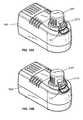
- FIG. 11Ais a first perspective view of a charger according to an embodiment of the invention.
- FIG. 11Bis a second perspective view of the charger shown in FIG. 11A .
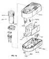
- FIG. 12is an exploded view of a battery and the charger shown in FIG. 11A .
- FIG. 13is a top view of the charger shown in FIG. 11A .
- FIG. 14is a bottom view of the charger shown in FIG. 11A .
- FIG. 15Ais a first perspective view of the charger shown in FIG. 11A supporting a for charging.
- FIG. 15Bis a second perspective view of the charger shown in FIG. 11A supporting a for charging.
- FIG. 16is a top view of the charger and inserted battery shown in FIG. 15A .
- FIG. 17is a first cross-sectional view of the charger and battery assembly shown in 15 A- 16 .
- FIG. 18is a second cross-sectional view of the charger and battery assembly shown in 15 A- 16 .
- FIG. 19is a third cross-sectional view of the charger and battery assembly shown in 15 A- 16 .
- FIG. 20is a fourth cross-sectional view of the charger and battery assembly shown in 15 A- 16 .
- FIG. 21is a schematic illustration of the power tool shown in FIG. 1 .
- FIGS. 1-5illustrate a hand-held, battery-operated power tool 10 , such as, for example, a screwdriver, a drill, or another rotary tool.
- the power tool 10is operable to receive power from a battery, such as the battery 200 shown in FIGS. 6-9C .
- the power tool 10can be another hand-held power tool, such as, for example, a reciprocating saw, a hammer drill, a router, a circular saw, a grinder, a sander, etc.
- the power tool 10includes a housing assembly 12 having a body 14 and a main operator's handle portion or hand grip 16 connected to a rearward portion 18 of the body 14 .
- the body 14defines a longitudinal body axis 22 and houses a drive mechanism 26 , a motor 28 , and a spindle 30 supported by a forward end 31 of the body 14 .
- the drive mechanism 26 , the motor 28 , and the spindle 30are operable to rotate a tool element (not shown) generally about a tool axis for working on a workpiece (also not shown).
- the drive mechanism 26 , the motor 28 , and the spindle 30can also or alternatively reciprocate the tool element along the tool axis for working on a workpiece.
- the spindle 30is a tool-less spindle, which can accept and lockingly engage the tool element.
- the tool elementis secured to the spindle 30 by a ball-detent arrangement and requires no tools for tool element insertion or removal.
- a chuck, collets, a blade clamp, adapters, or other conventional connecting structuremay be used to secure a tool element to the spindle 30 .
- the hand grip 16is pivotably connected to the rearward portion 18 of the body 14 rearwardly of the motor 28 .
- the hand grip 16defines a grip axis 32 and is supported for pivoting movement relative to the body 14 about a pivot axis 34 .
- the pivot axis 34is substantially perpendicular to both the body axis 22 and the grip axis 32 .
- the orientation of the axes 22 , 32 , and 34may be different, such as, for example, generally parallel or skew.
- the hand grip 16may be movable in other manners, such as, for example, slidably, rotatably, or pivotably about two axes (i.e., about the pivot axis 34 and about an axis parallel to the body axis 22 and/or to the grip axis 32 ).
- the body 14is formed of two body halves 14 a , 14 b (see FIG. 3 ).
- the hand grip 16is formed of two grip halves 16 a , 16 b (also shown in FIG. 3 ).
- a first end 40 of the hand grip 16sandwiches the rearward portion 18 of the body 14 .
- a pivot pin 42defining the pivot axis 34 , extends through the first end 40 of the hand grip 16 and through the rearward portion 18 of the body 14 to pivotally connect the hand grip 16 to the body 14 .
- the hand grip 16is movable relative to the body 14 between a first position (shown in FIG. 1 ), in which the body axis 22 and the grip axis 32 are generally aligned and are substantially parallel, and a second position (shown in FIG. 2 ), in which the grip axis 32 is misaligned with the body axis 22 .
- the hand grip 16In the second position, the hand grip 16 is positioned so that the grip axis 32 and the body axis 22 define an angle ⁇ of between about 90 degrees and about 135 degrees.
- the hand grip 16may also be movable to one or more positions between the first and second positions.
- the hand grip 16is pivotable relative to the body 14 to change the length of the power tool 10 , measured from a forward end 31 of the body 14 to a rearward end 44 of the hand grip 16 .
- the power tool 10has a first length measured between the forward end 31 of the body 14 and the rearward end 44 of the hand grip 16 .
- the power tool 10has a second shorter length measured between the forward end 31 of the body 14 and the rearward end 44 of the hand grip 16 .
- the motor 28is an electric motor that is connectable to a power source, such as the battery 200 , by an electrical circuit 310 (shown schematically in FIG. 21 ).
- the battery 200is removably supported in a battery chamber 56 extending through the rearward end 44 of the hand grip 16 and is slidably attached to the hand grip 16 in a direction generally parallel to the grip axis 32 .
- the hand grip 16can support two or more batteries 200 in a battery chamber 56 , or alternatively, the battery(ies) 200 can be slidably connected to an outer engagement surface of the hand grip 16 .
- the power tool 10includes an on/off switch assembly 74 which is operable to connect the motor 28 to the power source.
- the switch assembly 74includes a direction switch 76 (shown in FIG. 21 ) having a trigger 77 supported on a side surface 78 of the body 14 for operation by the thumb or finger of either a right-handed or a left-handed operator.
- the trigger 77is positioned toward the rear of the body 14 , near the hand grip 16 .
- at least a portion of the switch assembly 74such as the trigger 77 , is movable with the body 14 relative to the hand grip 16 during pivoting movement of the hand grip 16 .
- the power and direction of rotation of the motor 28may be controlled by other elements and structure.
- a single triggercan be actuated to cause the motor shaft 58 to rotate relative to the body 14 .
- the direction of rotation of the motor shaft 58can be controlled by a separate direction switch, which may be operable between a “forward” position and a “reverse” position, and may additionally be provided with a lockout feature to prevent actuation of the trigger and energization of the motor 28 .
- the power tool 10can include a speed control mechanism 82 , which is operable to adjust the rotational speed of a tool element supported by the power tool 10 and/or the rotational speed of the spindle 30 between two or more different rotational speeds (e.g., a high speed, a low speed, and intermediate speeds). As shown in FIGS.
- the speed control mechanism 82can be supported on an upper surface 84 of the body 14 and can be operable to move the drive mechanism 26 between a first configuration, in which elements of the drive mechanism 26 are oriented to rotate a tool element and/or the spindle 30 about the tool axis at a first rotational speed, and a second configuration, in which elements of the drive mechanism 26 are oriented to rotate a tool element about the tool axis at a second, different rotational speed.
- the speed control mechanism 82may be operable to control the power supplied by the power source (e.g., the battery 200 ) to the motor 28 to rotate the motor shaft 58 at a first rotational speed and a second, different rotational speed.
- the power tool 10also includes a locking assembly 110 for locking the hand grip 16 in a position relative to the body 14 .
- the locking assembly 110is operable between a locked position, in which the hand grip 16 is fixed in a position relative to the body 14 , and an unlocked position, in which the position of the hand grip 16 relative to the body 14 is adjustable.
- the locking assembly 110may be substantially similar to that disclosed in U.S. patent application Ser. No. 09/704,914, filed Nov. 2, 2000 and/or U.S. patent application Ser. No. 10/796,365, filed Mar. 9, 2004, the entire contents of each of which is hereby incorporated by reference.
- the locking assembly 110includes a detent arrangement between the hand grip 16 and the body 14 to provide a positive engagement between the hand grip 16 and the body 14 .
- the locking assembly 110includes a locking member 112 , a portion of which is selectively engageable in a first recess, to fix the hand grip 16 in the first position relative to the body 14 , and a second recess, to fix the hand grip 16 in the second position relative to the body 14 .
- the locking assembly 110can also include additional recesses in which the locking member 112 can be engageable to fix the hand grip 16 in additional positions relative to the body 14 .
- the locking assembly 110can also include an actuator 114 for moving the locking member 112 between the locked and unlocked positions.
- the actuator 114is positioned on an upper surface 84 of the body 14 for operation by the thumb or finger of either a right-handed or a left-handed operator. A portion of the actuator 114 extends through the housing 12 and is selectively engageable with the locking member 112 to move the locking member 112 between the locked and unlocked positions.
- the locking assembly 110can include a biasing member, such as a spring, for biasing the locking member 112 toward the locked position, or alternatively, for biasing the locking member 112 toward the unlocked position.
- the actuator 114is operated to move the locking projection 114 out of engagement with the recesses.
- the hand grip 16is then moved relative to the body 14 to a position corresponding to engagement of the locking projection 114 with one of the recesses.
- the locking projection 114is moved (e.g., by a spring) into the corresponding recess.
- the locking assembly 10may include a different locking arrangement, such as a frictional engagement between the hand grip 16 and the body 14 .
- the locking assembly 10may also include a positive engagement arrangement, such as inter-engaging teeth formed on the body 14 and the hand grip 16 which are engaged when the locking assembly 110 is in the locked condition.
- the locking assembly 110may also include a pivoting lockout, which prevents the hand grip 16 from being pivoted about the pivot axis 34 relative to the body 14 when the motor 28 is in operation and/or when the switch assembly 74 is activated.
- the power tool 10can also include a fuel gauge 118 for displaying a state of charge of the battery 200 supported in the battery chamber 56 .
- the fuel gauge 118can include a display 120 positioned on a side of the hand grip 16 .
- the display 120can include a series of indicator lights 122 (e.g., light-emitting diodes) arranged to form a scale.
- a number of indicator lights 122can be illuminated when the battery state of charge is high and one or no lights can be illuminated to show that the battery state of charge is low. In other embodiments, one light can flash to show that the battery state of charge is low.
- the display 120can include other display screens and/or indicator lights having other relative orientations and positions and can include indicator lights of different colors (e.g., green, blue, yellow, orange, and red) for displaying the state of charge of the battery 200 .
- the display 120can be used to inform the user of other conditions, such as, for example, abnormal (high or low) battery temperature, an electrical fault within the electrical circuit 310 , or other information pertaining to the battery 200 or tool 10 .
- the electrical circuit 310includes a controller 320 .
- the controller 320can perform various functions within the tool 10 , such as, for example, measuring various battery conditions (e.g., state of charge of battery cell 208 ), controlling various components included in the circuit 310 (e.g., the fuel gauge 118 ), controlling operation of the power tool 10 , and gathering and storing data pertaining to tool operation, battery conditions, and component operation within the circuit 310 .
- the controller 320 and/or electrical circuit 310can include similar components and/or perform similar functions as the battery controllers and electrical circuits shown and described in U.S. patent application Ser. No. 10/720,027, filed Nov. 20, 2003 and U.S. patent application Ser. No. 11/138,070, filed May 24,2005, the entire contents of each of which is hereby incorporated by reference.
- the controller 320is programmed to measure state of charge in response to the activation of the trigger 77 , as discussed below.
- the battery state of charge datais measured prior to activation of the motor 28 ; that is, before the battery state of charge is effected by the current draw being supplied to the motor 28 .
- This measurement of the battery state of chargerepresents an at rest state of charge of the battery 200 .
- only the at rest state of charge measurementsare displayed on the fuel gauge 118 .
- the state of charge datais displayed for a predetermined time after the trigger 77 is actuated. In one embodiment, the predetermined time is approximately two (2) seconds. In other embodiments, the predetermined time can be greater than two (2) seconds.
- the predetermined timecan be less than two (2) seconds.
- the display 120can be cleared. In one embodiment, the display 120 is cleared when the predetermined time expires regardless whether the trigger 77 is still actuated. In some embodiments, the display 120 is cleared when the predetermined time expires regardless of the trigger 77 activity. In still further embodiments, the display 120 is cleared prior to expiration of the predetermined time (e.g., approximately two (2) seconds) when the trigger 77 is released.
- the circuit 310also includes the direction switch 76 which controls and/or selects the rotational direction of the motor shaft 58 .
- the circuit 310also includes an on/off switch 330 , a brake 335 , a mechanical torque clutch 340 and a temperature sensing device or thermistor 350 .
- the on/off switch 330 and the brake 335can include a field effect transistor, such as a MOSFET.
- the on/off switch 330is controlled by the controller 320 and activated by the controller 320 under various conditions.
- the controller 320activates the on/off switch 330 to a conducting state for power to be delivered to the motor 28 in response to activation of the trigger 77 .
- the controller 320can also activate the switch 330 to a non-conducting state to interrupt current being supplied to the motor 28 when the state of charge of the battery 200 reaches a cut-off threshold or when an overload condition is sensed by the controller 320 .
- an overload conditioncan occur when the temperature of the battery 200 as sensed by the controller 320 via the thermistor 350 reaches a high temperature threshold or when the current being supplied to the motor 320 reaches a high current threshold.
- the controller 320can indicate to a user that an overload condition has occurred via the display 120 , such as flashing one or more lights 122 .
- the brake 335is controlled by the controller 320 and activated by the controller 320 when the torque of the motor 28 exceeds the torque setting of the tool 10 as sensed by controller 320 via the clutch 340 .
- the battery 200 of the illustrated embodimentis substantially cylindrically shaped and has a substantially circular cross-section.
- the battery 200can have any other shape and/or cross-sectional shape, including without limitation rectangular, oval, polygonal, irregular, etc.
- the battery 200includes a battery sleeve or casing 204 and a battery cell 208 supported in the battery casing 204 .
- the battery 200can also include a cap 206 , which can be secured to a second end 205 of the battery casing 204 to substantially enclose the battery cell 208 .
- the battery 200can include two or more battery cells 208 arranged in various combinations of serial and parallel cell arrangements.
- the battery 200includes a single battery cell 208 having a nominal voltage rating of approximately 4.0 volts (V) and a capacity of approximately 3.0 Ampere-hours (Ah).
- the battery cell 208also has a Lithium-based chemistry, such as, for example a Li-ion chemistry.
- the Lithium-based chemistrycan include various Li-ion chemistries, such as, for example, Lithium Cobalt, Lithium Manganese (“Li—Mn”) Spinel, or Li—Mn Nickel. As shown in FIGS.
- contact recesses 216 a , 216 bextend radially through a first end 203 of the casing 204 .
- the contact recesses 216 a , 216 bare generally L-shaped.
- one or both of the contact recesses 216 a , 216 bcan have other shapes and can be positioned in other locations along the battery casing 204 .
- the battery 200also includes a first (e.g., a negative) battery terminal 202 a and second (e.g., a positive) battery terminal 202 b , portions of which are accessible through the contact recesses 216 a , 216 b to electrically connect the battery cell 208 to the corresponding electrical terminals (not shown) of the power tool 10 , or alternatively, to the electrical terminals (not shown) of a battery charger.
- the battery terminals 202 a and 202 bcan also or alternatively at least partially physically connect the battery 200 to the hand grip 16 of the power tool 10 .
- the battery terminals 202 a , 202 bare equally spaced circumferentially (e.g., approximately 180 degrees apart) around a front end of the battery cell 208 .
- the battery terminals 202 a , 202 bcan have other orientations and locations, depending in part on the location and orientation of the contact recesses 216 a , 216 b.
- the battery 200when a battery 200 is inserted into the battery chamber power tool 10 , the battery 200 can be pivoted about the battery axis 201 , which can be coincident with the grip axis 32 so that the first battery terminal 202 a of the battery 200 wipes across the electrical terminal of the power tool, cleaning the battery terminal 202 a of the battery 200 and the corresponding power tool terminal before an electrical connection is established the battery 200 and the power tool 10 .
- the second battery terminal 202 b of the battery 200can be wiped across the electrical terminal of the power tool, cleaning the electrical connector 202 b of the battery 200 and the corresponding power tool terminal.
- the first and second battery terminals 202 a , 202 b of the battery 200 and the first and second terminals of the power toolare cleaned each time a battery 200 is electrically connected to the power tool 10 and/or each time a battery 200 is disconnected from the power tool 10 .
- a retainer clip 210is supported in the battery casing 204 and is operable to position and retain the battery terminals 202 a , 202 b and the battery cell 208 in their respective locations and orientations within the battery casing 204 .
- the retainer clip 210includes a radially outwardly extending projection 211 , which is engageable in a recess (not shown) in the battery casing 204 to orient the retainer clip 210 in a predetermined orientation in the battery casing 204 .
- the retainer clip 210can also include two recesses 212 , 213 for receiving portions of the battery terminals 202 a , 202 b , respectively.
- the battery terminals 202 a , 202 bare fixed in a predetermined circumferential orientation with respect to the battery casing 204 .
- an insulator 214(e.g., a foam insert) is located between a front end of the battery cell 208 and the cap 206 .
- the cap 206is positioned over the insulator 214 and secured to the battery casing 204 by a pair of cap-retaining barbs 215 , which extend radially outwardly from the casing 204 .
- the cap 206can be connected to the casing 204 via screws, bolts, nails, rivets, pins, posts, clips, clamps, and/or other conventional fasteners, inter-engaging elements on the cap 206 and the casing 204 (e.g., tabs, flanges, or other extensions inserted within slots, grooves, or other apertures, etc.), by adhesive or cohesive bonding material, or in any other suitable manner.
- the battery 200includes a locking arrangement 220 for locking the battery 200 in the battery chamber 56 of the power tool 10 .
- the locking arrangement 220includes first and second lugs 222 a , 222 b , which extend radially outwardly from the casing 204 of the battery 200 .
- first and second lugs 222 a , 222 beach have generally rectangular cross-sectional shapes, and the first lug 222 a is larger in size than the second lug 222 b .
- the first and second lugs 222 a , 222 bcan have any other shape and/or cross-sectional shape, including without limitation round, oval, polygonal, irregular, etc.
- Corresponding slotsextend axially along the sides of the battery chamber 56 of the power tool 10 .
- One of these slotsis sized and shaped to receive the first lug 222 a and the other slot is sized and shaped to receive the second lug 222 b , thereby ensuring that the battery 200 can only be inserted into the power tool 10 in a single desired orientation (i.e., with the battery terminals 202 a , 202 b of the battery 200 aligned with and electrically connected to corresponding terminals of the power tool 10 ).
- the slotsextend axially along the inner wall of the battery chamber 56 of the power tool 10 and include lower ends which extend circumferentially around at least a portion of the inner wall of the battery chamber 56 .
- the slotsare substantially L-shaped. In this manner, after the battery 200 is inserted axially into the battery chamber 56 of the power tool 10 , the battery 200 can be pivoted about the battery axis 201 and relative to the housing 12 to lockingly engage the lugs 222 a , 222 b in the respective L-shaped receiving slots to lockingly connect the battery 200 to the power tool 10 .
- the locking arrangement 220may include a single lug and a single receiving slot.
- the battery 200can also include axially extending projections 224 located on the front end of the battery 200 opposite the cap 206 .
- the projections 224can be engageable with a complementary part(s) in the battery chamber 56 to provide tactile and/or audible feedback to the operator upon rotation of the battery 200 relative to the hand grip 16 .
- the battery 200can have a single projection 224 or more than two projections 224 , which can be placed on the battery casing 204 at various locations for engagement with the battery chamber 56 .
- the projections 224can be engageable with a complementary part(s) in a battery charger 400 to provide tactile and/or audible feedback to the operator upon rotation of the battery 200 relative to the battery charger 400 .
- the battery 200is engageable in a battery charger 400 , which is operable to charge one or more battery(ies) 200 .
- AC current from an electrical sourcee.g., a land-based power network
- the charging circuit 401may convert AC power to DC power.
- the battery charger 400can provide power to the battery 200 from an unconventional power source including supplementary batteries and various AC and DC sources.
- the charging circuit 401can include AC/DC converting components and can also or alternatively provide current and/or voltage limiting functions, signal conditioning, and the like.
- the charging circuit 401can include similar components and implement similar charging algorithms as the charging circuits shown and described in U.S. patent application Ser. No. 10/719,680, filed Nov. 20, 2003, U.S. patent application Ser. No. 11/139,020, filed May 24, 2005, and U.S. patent application Ser. No. 11/266,007, filed Nov. 2, 2005, the entire contents of each of which is hereby incorporated by reference.
- the charger 400includes a charger casing or body 402 having an upper portion 402 a and a lower portion 402 b .
- the casing 402can define a battery chamber 403 and can include an opening 404 for receiving batteries 200 .
- the opening 404is located generally toward the front end 406 of the charger 400 .
- a rear portion 408 of the charger 400is provided with an electrical input receptacle 410 for receiving a cord or plug.
- first and second receiving slots 418 a , 418 bextend through the charger casing 402 on opposite sides of the opening 404 and are sized to engage portions of the battery 200 to retain the battery 200 in the charger 400 and to orient the battery 200 with respect to the charger 400 .
- the receiving slots 418 a , 418 bare similar in size, shape, and relative orientation to the receiving slots in the battery chamber 56 of the power tool 10 .
- the receiving slots 418 a , 418 bcan be differently sized so that the battery 200 can only be inserted into the battery chamber 403 in a required orientation (i.e., battery terminals 202 a , 202 b engaging respective terminals 420 a , 420 b of the battery charger 400 ).
- the receiving slots 418 a , 418 bare generally L-shaped.
- the battery 400can be pivoted about the battery axis 201 and relative to the casing 402 from an unlocked position, in which the battery 200 is movable axially out of the opening 404 , toward a locked position, in which the engagement between the lugs 222 a , 222 b and the receiving slots 418 a , 418 b prevents the battery 200 from being moved axially out of the battery chamber 403 .
- the charger 400can include an indicator 419 located on an outer surface of the casing 402 and the battery 200 can include a similar indicator 223 .
- the indicator 419 of the charger 400 and the indicator 223 of the battery 200are misaligned, the operator will be able to confirm that the battery 200 is in the unlocked position.
- the indicator 419 of the charger 400 and the indicator 223 of the battery 200are aligned, the operator will be able to confirm that the battery 200 is in the locked position.
- the terminals 420 a , 420 b of the battery charger 400can extend circumferentially around at least a portion of the battery chamber 403 so that the terminals 202 a , 202 b can be electrically connected to respective terminals 420 a , 420 b of the battery charger 400 when the battery 200 is in the locked and unlocked positions.
- the charger 400is operable to charge the battery 200 while the battery 200 is in either the locked position or the unlocked position. This can be a convenience for operators, some of whom may wish to quickly insert the battery 200 for charging without having to pivot the battery 200 toward a locked position.
- operatorscan insert the battery 200 into the battery chamber 403 and pivot the battery 200 toward the locked position so that the battery 200 can be charged and so that the battery 200 does not fall out of the charger 400 during charging.
- the charger 400can include mounting receptacles 428 for mounting the charger 400 on a wall or other inclined surface, or alternatively, for securing the charger 400 to a work cart, a horizontal surface, a work table or bench, and the like.
- the charger 400can also include feet 430 for supporting the charger 400 .
- the charger 400can also include detents 422 for engagement with the projections 224 on the battery 200 to provide tactile and/or audible feedback to the operator indicate to the operator that the operator has moved the battery 200 to the locked position, or alternatively, to the unlocked position.
- the detents 422are elastically deformable and extend horizontally across the lower end of the battery chamber 403 .
- the detents 422can have other relative orientations and positions.
- the detents 422can extend circumferentially around the side walls of the battery chamber 403 for engagement with corresponding battery projections 224 located on the sides of the battery 200 .
- a charge indicator 412(e.g., a light-emitting diode (LED) or another light) can be supported on the upper charger casing 402 a for displaying charge data to an operator (e.g., charge time remaining, charging in progress, charging complete, etc.).
- the charger 400can also or alternatively include other indicators or displays.
- an operatorgrasps the hand grip 16 with a first hand and grasps the body 14 with a second hand and pivots the hand grip 16 about the pivot axis 34 from the first position (shown in FIG. 1 ) toward the second position (shown in FIG. 2 ).
- the operatorcan move the actuator 114 with respect to the housing 12 to move the locking member 112 from the locked position toward the unlocked position before and/or during pivoting of the body 14 and hand grip 16 .
- the operatorcan insert a tool into the spindle 30 .
- the operatorcan also insert the battery 200 into the battery chamber 56 to provide power to the power tool 10 .
- the operatorcan then move the trigger 77 toward an operational position, in turn engaging the direction switch 76 .
- the trigger 77is activated, power is supplied to the electrical circuit 310 from the battery 200 and the controller 320 wakes from a low power state.
- the controller 320takes a state of charge reading from the battery 200 , stores the reading in the controller's internal memory (not shown) and activates the fuel gauge 118 to display the current at rest state of charge of the battery 200 .
- the controller 320switches the normally non-conducting on/off switch 330 into the conducting state such that current is supplied from the battery cell 208 to the motor 28 as determined by the directional switch 76 , causing the motor 28 to rotate the spindle 30 and the tool element.
- the controller 320continues to display the state of charge reading via the fuel gauge 118 until the predetermined time period expires.
- the operatorcan then move the hand grip 16 from the second position back to the first position, or alternatively, to an intermediate position (not shown) to orient the power tool 10 to operate in a confined workspace and/or to perform a different operation.
- an operatormay pivot the hand grip 16 about the pivot axis 34 and relative to the body 14 with a flick of the wrist and/or by grasping one of the hand grip 16 and the body 14 with one hand and pressing the other of the hand grip 16 and the body 14 against his body.
- the on/off switch 330is positioned in the non-conducting state and the controller 320 beings to count down the waiting period.
- the controller 320approximates the battery's current state of charge based on the previous state of charge reading and the time duration that the motor 28 was running and displays that approximation. In some constructions, if the time duration that the motor 28 was running is longer than a predetermined time period, the controller 320 does not calculate or approximate a current state of charge reading of the battery and does not display any battery state of charge reading on the fuel gauge 118 .
- the controller 320takes another at rest battery state of charge reading prior to activation of the on/off switch 330 and power being supplied to the motor 28 , as discussed above.
- the operatorcan remove the battery 200 from the power tool 10 and insert the battery 200 into the charger 400 to recharge the battery 200 .
- the operatorcan insert the battery 200 axially into the battery chamber 403 of the battery charger 400 to initiate battery charging.
- the operatorcan pivot the battery 200 toward a locked position so that the battery 200 is lockingly secured to the battery charger 400 during charging.
- the operatorcan remove the battery 200 from the charger 400 and insert the newly charged battery 200 into the battery chamber 56 of the power tool 200 .
- the operatorcan depress the trigger 77 , causing the state of charge data to be shown on the display 120 .
Landscapes
- Engineering & Computer Science (AREA)
- Power Engineering (AREA)
- Mechanical Engineering (AREA)
- Manufacturing & Machinery (AREA)
- Chemical & Material Sciences (AREA)
- Chemical Kinetics & Catalysis (AREA)
- Electrochemistry (AREA)
- General Chemical & Material Sciences (AREA)
- Battery Mounting, Suspending (AREA)
- Portable Power Tools In General (AREA)
- Charge And Discharge Circuits For Batteries Or The Like (AREA)
- Secondary Cells (AREA)
Abstract
Description
This application claims priority under 35 U.S.C. § 119 to Provisional Patent Application No. 60/682,192 filed on May 17, 2005, the entire contents of which is hereby incorporated by reference.
The present application incorporates by reference the entire contents of U.S. patent application Ser. No. 11/435,596, filed May 17, 2006.
The present invention relates generally to power tools, and more particularly to rotary power tools, such as drills and screwdrivers.
Power tools, such as rotary power tools, are used to work on or cut a variety of workpieces, such as metal, wood, drywall, etc. Such tools typically include a housing, a motor supported by the housing and connectable to a power source, and a spindle rotatably supported by the housing and selectively driven by the motor. A tool holder, such as a chuck, is mounted on the forward end of the spindle, and a tool element, such as, for example, a drill bit, is mounted in the chuck for rotation with the chuck and with the spindle to operate on a workpiece.
In some embodiments, the invention provides a method of operating a power tool. The power tool can include a housing supporting a motor, a switch assembly, and a fuel gauge. The method can include the acts of activating the switch assembly to electrically connect the motor and a battery, recording a state of charge of the battery, displaying the state of charge of the battery on the fuel gauge before electrically connecting the motor and the battery, and stopping the display of the state of charge before deactivating the switch assembly.
In other embodiments, the invention provides a method of operating a power tool including a housing supporting a motor and a fuel gauge. The method can include the acts of connecting a battery to the housing, the battery having an at rest state of charge, displaying the at rest state of charge of the battery on the fuel gauge, and activating the motor and continuing to display the at rest state of charge of the battery on the fuel gauge.
The invention also provides a power tool including a movable spindle for supporting a tool element, and a housing supporting a motor and a drive mechanism driven by the motor. The drive mechanism can be operably connected to the spindle for causing movement of the spindle relative to the housing. The housing can have a forward end supporting the spindle and a rearward end. The power tool can also include a battery connectable to the rearward end, and a fuel gauge supported on the housing for displaying an at rest state of charge of the battery.
In some embodiments, the invention provides a method of operating a battery charger. The battery charger can include a body defining an aperture and a charging circuit extending through the body. The method can include the acts of inserting a battery into the aperture along an insertion axis, electrically connecting the battery to the charging circuit to charge the battery and pivoting the battery about the axis relative to the battery charger to secure the battery in the battery charger.
In other embodiments, the invention provides a method of operating a battery charger. The battery charger can include a body and a charging circuit. One of the charger and the battery can include an outwardly extending protrusion, and the other of the charger and the battery can define a recess for receiving the outwardly extending protrusion. The method can include the acts of electrically connecting the battery and the charging circuit to charge the battery before engaging the protrusion in the recess to secure the battery to the body of the charger.
In other embodiments, the invention provides a method of operating a battery charger. The battery charger can include a body and a charging circuit extending through the body. The method can include the acts of electrically connecting the battery to the charging circuit to charge the battery, and moving the battery with respect to the battery charger to secure the battery to the body while continuing to charge the battery.
The invention also provides a combination of a battery and a battery charger. The battery can include a casing and a battery cell supported in the casing. The battery charger can include a body and a charging circuit. One of the charger and the battery can include an outwardly extending protrusion, and the other of the charger and the battery can define a recess for receiving the outwardly extending protrusion. The battery can be movable relative to the body of the charger between a locked position, in which the protrusion can lockingly engage the recess and an unlocked position, in which the protrusion can removably engage the recess. The battery cell can be electrically connectable to the charging circuit of the battery charger when the battery is in the locked position and the unlocked position.
Other aspects of the invention will become apparent by consideration of the detailed description and accompanying drawings.
Before any embodiments of the invention are explained in detail, it is to be understood that the invention is not limited in its application to the details of embodiment and the arrangement of components set forth in the following description or illustrated in the following drawings. The invention is capable of other embodiments and of being practiced or of being carried out in various ways. Also, it is to be understood that the phraseology and terminology used herein is for the purpose of description and should not be regarded as limiting. The use of “including,” “comprising,” or “having” and variations thereof herein is meant to encompass the items listed thereafter and equivalents thereof as well as additional items. Unless specified or limited otherwise, the terms “mounted,” “connected,” “supported,” and “coupled” and variations thereof are used broadly and encompass both direct and indirect mountings, connections, supports, and couplings. Further, “connected” and “coupled” are not restricted to physical or mechanical connections or couplings.
Thepower tool 10 includes ahousing assembly 12 having abody 14 and a main operator's handle portion orhand grip 16 connected to arearward portion 18 of thebody 14.
Thebody 14 defines alongitudinal body axis 22 and houses adrive mechanism 26, amotor 28, and aspindle 30 supported by aforward end 31 of thebody 14. Together, thedrive mechanism 26, themotor 28, and thespindle 30 are operable to rotate a tool element (not shown) generally about a tool axis for working on a workpiece (also not shown). In other embodiments, thedrive mechanism 26, themotor 28, and thespindle 30 can also or alternatively reciprocate the tool element along the tool axis for working on a workpiece.
In the illustrated embodiment ofFIGS. 1-5 , thespindle 30 is a tool-less spindle, which can accept and lockingly engage the tool element. The tool element is secured to thespindle 30 by a ball-detent arrangement and requires no tools for tool element insertion or removal. In other embodiments, a chuck, collets, a blade clamp, adapters, or other conventional connecting structure may be used to secure a tool element to thespindle 30.
As shown inFIGS. 1-5 , thehand grip 16 is pivotably connected to therearward portion 18 of thebody 14 rearwardly of themotor 28. Thehand grip 16 defines agrip axis 32 and is supported for pivoting movement relative to thebody 14 about apivot axis 34. In the illustrated embodiment, thepivot axis 34 is substantially perpendicular to both thebody axis 22 and thegrip axis 32.
In other embodiments (not shown), the orientation of theaxes hand grip 16 may be movable in other manners, such as, for example, slidably, rotatably, or pivotably about two axes (i.e., about thepivot axis 34 and about an axis parallel to thebody axis 22 and/or to the grip axis32).
In some embodiments, thebody 14 is formed of two body halves14a,14b(seeFIG. 3 ). Similarly, thehand grip 16 is formed of two grip halves16a,16b(also shown inFIG. 3 ). In these embodiments, afirst end 40 of thehand grip 16 sandwiches therearward portion 18 of thebody 14. Apivot pin 42, defining thepivot axis 34, extends through thefirst end 40 of thehand grip 16 and through therearward portion 18 of thebody 14 to pivotally connect thehand grip 16 to thebody 14.
Thehand grip 16 is movable relative to thebody 14 between a first position (shown inFIG. 1 ), in which thebody axis 22 and thegrip axis 32 are generally aligned and are substantially parallel, and a second position (shown inFIG. 2 ), in which thegrip axis 32 is misaligned with thebody axis 22. In the second position, thehand grip 16 is positioned so that thegrip axis 32 and thebody axis 22 define an angle α of between about 90 degrees and about 135 degrees. Thehand grip 16 may also be movable to one or more positions between the first and second positions.
Also, thehand grip 16 is pivotable relative to thebody 14 to change the length of thepower tool 10, measured from aforward end 31 of thebody 14 to arearward end 44 of thehand grip 16. In the position shown inFIG. 1 , thepower tool 10 has a first length measured between theforward end 31 of thebody 14 and therearward end 44 of thehand grip 16. In the position shown inFIG. 2 , thepower tool 10 has a second shorter length measured between theforward end 31 of thebody 14 and therearward end 44 of thehand grip 16.
With respect to the illustrated embodiment ofFIGS. 1-5 , themotor 28 is an electric motor that is connectable to a power source, such as thebattery 200, by an electrical circuit310 (shown schematically inFIG. 21 ). Thebattery 200 is removably supported in abattery chamber 56 extending through therearward end 44 of thehand grip 16 and is slidably attached to thehand grip 16 in a direction generally parallel to thegrip axis 32. In other embodiments, thehand grip 16 can support two ormore batteries 200 in abattery chamber 56, or alternatively, the battery(ies)200 can be slidably connected to an outer engagement surface of thehand grip 16.
Thepower tool 10 includes an on/offswitch assembly 74 which is operable to connect themotor 28 to the power source. In the illustrated embodiment ofFIGS. 1-5 , theswitch assembly 74 includes a direction switch76 (shown inFIG. 21 ) having atrigger 77 supported on aside surface 78 of thebody 14 for operation by the thumb or finger of either a right-handed or a left-handed operator. In the illustrated embodiment, thetrigger 77 is positioned toward the rear of thebody 14, near thehand grip 16. As shown inFIGS. 1-5 , at least a portion of theswitch assembly 74, such as thetrigger 77, is movable with thebody 14 relative to thehand grip 16 during pivoting movement of thehand grip 16.
In other embodiments (not shown), the power and direction of rotation of themotor 28 may be controlled by other elements and structure. In one such alternate embodiment, a single trigger can be actuated to cause the motor shaft58 to rotate relative to thebody 14. The direction of rotation of the motor shaft58 can be controlled by a separate direction switch, which may be operable between a “forward” position and a “reverse” position, and may additionally be provided with a lockout feature to prevent actuation of the trigger and energization of themotor 28.
In some embodiments, thepower tool 10 can include aspeed control mechanism 82, which is operable to adjust the rotational speed of a tool element supported by thepower tool 10 and/or the rotational speed of thespindle 30 between two or more different rotational speeds (e.g., a high speed, a low speed, and intermediate speeds). As shown inFIGS. 1-5 , thespeed control mechanism 82 can be supported on anupper surface 84 of thebody 14 and can be operable to move thedrive mechanism 26 between a first configuration, in which elements of thedrive mechanism 26 are oriented to rotate a tool element and/or thespindle 30 about the tool axis at a first rotational speed, and a second configuration, in which elements of thedrive mechanism 26 are oriented to rotate a tool element about the tool axis at a second, different rotational speed. In other embodiments, thespeed control mechanism 82 may be operable to control the power supplied by the power source (e.g., the battery200) to themotor 28 to rotate the motor shaft58 at a first rotational speed and a second, different rotational speed.
As shown inFIGS. 1-5 , thepower tool 10 also includes a lockingassembly 110 for locking thehand grip 16 in a position relative to thebody 14. The lockingassembly 110 is operable between a locked position, in which thehand grip 16 is fixed in a position relative to thebody 14, and an unlocked position, in which the position of thehand grip 16 relative to thebody 14 is adjustable. In some embodiments, the lockingassembly 110 may be substantially similar to that disclosed in U.S. patent application Ser. No. 09/704,914, filed Nov. 2, 2000 and/or U.S. patent application Ser. No. 10/796,365, filed Mar. 9, 2004, the entire contents of each of which is hereby incorporated by reference.
In the illustrated embodiment, the lockingassembly 110 includes a detent arrangement between thehand grip 16 and thebody 14 to provide a positive engagement between thehand grip 16 and thebody 14. The lockingassembly 110 includes a lockingmember 112, a portion of which is selectively engageable in a first recess, to fix thehand grip 16 in the first position relative to thebody 14, and a second recess, to fix thehand grip 16 in the second position relative to thebody 14. The lockingassembly 110 can also include additional recesses in which the lockingmember 112 can be engageable to fix thehand grip 16 in additional positions relative to thebody 14.
The lockingassembly 110 can also include anactuator 114 for moving the lockingmember 112 between the locked and unlocked positions. In the illustrated embodiment ofFIGS. 1-5 , theactuator 114 is positioned on anupper surface 84 of thebody 14 for operation by the thumb or finger of either a right-handed or a left-handed operator. A portion of theactuator 114 extends through thehousing 12 and is selectively engageable with the lockingmember 112 to move the lockingmember 112 between the locked and unlocked positions. In some embodiments, the lockingassembly 110 can include a biasing member, such as a spring, for biasing the lockingmember 112 toward the locked position, or alternatively, for biasing the lockingmember 112 toward the unlocked position.
To move thehand grip 16 relative to thebody 14, theactuator 114 is operated to move the lockingprojection 114 out of engagement with the recesses. Thehand grip 16 is then moved relative to thebody 14 to a position corresponding to engagement of the lockingprojection 114 with one of the recesses. When thehand grip 16 is in the desired position, the lockingprojection 114 is moved (e.g., by a spring) into the corresponding recess.
In other embodiments (not shown), the lockingassembly 10 may include a different locking arrangement, such as a frictional engagement between thehand grip 16 and thebody 14. In such an embodiment, the lockingassembly 10 may also include a positive engagement arrangement, such as inter-engaging teeth formed on thebody 14 and thehand grip 16 which are engaged when the lockingassembly 110 is in the locked condition.
The lockingassembly 110 may also include a pivoting lockout, which prevents thehand grip 16 from being pivoted about thepivot axis 34 relative to thebody 14 when themotor 28 is in operation and/or when theswitch assembly 74 is activated.
Thepower tool 10 can also include afuel gauge 118 for displaying a state of charge of thebattery 200 supported in thebattery chamber 56. As shown inFIGS. 1 and 2 , thefuel gauge 118 can include adisplay 120 positioned on a side of thehand grip 16. In some embodiments, such as the illustrated embodiment ofFIGS. 1 and 2 , thedisplay 120 can include a series of indicator lights122 (e.g., light-emitting diodes) arranged to form a scale. In these embodiments a number ofindicator lights 122 can be illuminated when the battery state of charge is high and one or no lights can be illuminated to show that the battery state of charge is low. In other embodiments, one light can flash to show that the battery state of charge is low. In further embodiments, thedisplay 120 can include other display screens and/or indicator lights having other relative orientations and positions and can include indicator lights of different colors (e.g., green, blue, yellow, orange, and red) for displaying the state of charge of thebattery 200. In still further embodiments, thedisplay 120 can be used to inform the user of other conditions, such as, for example, abnormal (high or low) battery temperature, an electrical fault within theelectrical circuit 310, or other information pertaining to thebattery 200 ortool 10.
In some embodiments, such as the embodiment shown inFIG. 21 , theelectrical circuit 310 includes acontroller 320. Thecontroller 320 can perform various functions within thetool 10, such as, for example, measuring various battery conditions (e.g., state of charge of battery cell208), controlling various components included in the circuit310 (e.g., the fuel gauge118), controlling operation of thepower tool 10, and gathering and storing data pertaining to tool operation, battery conditions, and component operation within thecircuit 310. In other embodiments, thecontroller 320 and/orelectrical circuit 310 can include similar components and/or perform similar functions as the battery controllers and electrical circuits shown and described in U.S. patent application Ser. No. 10/720,027, filed Nov. 20, 2003 and U.S. patent application Ser. No. 11/138,070, filed May 24,2005, the entire contents of each of which is hereby incorporated by reference.
In some embodiments, thecontroller 320 is programmed to measure state of charge in response to the activation of thetrigger 77, as discussed below. In these embodiments, the battery state of charge data is measured prior to activation of themotor 28; that is, before the battery state of charge is effected by the current draw being supplied to themotor 28. This measurement of the battery state of charge represents an at rest state of charge of thebattery 200. In these embodiments, only the at rest state of charge measurements are displayed on thefuel gauge 118. In some embodiments, the state of charge data is displayed for a predetermined time after thetrigger 77 is actuated. In one embodiment, the predetermined time is approximately two (2) seconds. In other embodiments, the predetermined time can be greater than two (2) seconds. In further embodiments, the predetermined time can be less than two (2) seconds. After the predetermined time is exceeded, thedisplay 120 can be cleared. In one embodiment, thedisplay 120 is cleared when the predetermined time expires regardless whether thetrigger 77 is still actuated. In some embodiments, thedisplay 120 is cleared when the predetermined time expires regardless of thetrigger 77 activity. In still further embodiments, thedisplay 120 is cleared prior to expiration of the predetermined time (e.g., approximately two (2) seconds) when thetrigger 77 is released.
Thecircuit 310 also includes thedirection switch 76 which controls and/or selects the rotational direction of the motor shaft58. Thecircuit 310 also includes an on/offswitch 330, abrake 335, amechanical torque clutch 340 and a temperature sensing device orthermistor 350. In some embodiments, the on/offswitch 330 and thebrake 335 can include a field effect transistor, such as a MOSFET.
The on/offswitch 330 is controlled by thecontroller 320 and activated by thecontroller 320 under various conditions. For example, thecontroller 320 activates the on/offswitch 330 to a conducting state for power to be delivered to themotor 28 in response to activation of thetrigger 77. Thecontroller 320 can also activate theswitch 330 to a non-conducting state to interrupt current being supplied to themotor 28 when the state of charge of thebattery 200 reaches a cut-off threshold or when an overload condition is sensed by thecontroller 320. In some embodiments, an overload condition can occur when the temperature of thebattery 200 as sensed by thecontroller 320 via thethermistor 350 reaches a high temperature threshold or when the current being supplied to themotor 320 reaches a high current threshold. In these embodiments, thecontroller 320 can indicate to a user that an overload condition has occurred via thedisplay 120, such as flashing one ormore lights 122.
Thebrake 335 is controlled by thecontroller 320 and activated by thecontroller 320 when the torque of themotor 28 exceeds the torque setting of thetool 10 as sensed bycontroller 320 via the clutch340.
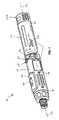
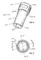
As shown inFIGS. 1-10 , thebattery 200 of the illustrated embodiment is substantially cylindrically shaped and has a substantially circular cross-section. In other embodiments, thebattery 200 can have any other shape and/or cross-sectional shape, including without limitation rectangular, oval, polygonal, irregular, etc.
In the illustrated embodiment ofFIGS. 1-10 , thebattery 200 includes a battery sleeve orcasing 204 and abattery cell 208 supported in thebattery casing 204. Thebattery 200 can also include acap 206, which can be secured to asecond end 205 of thebattery casing 204 to substantially enclose thebattery cell 208. In other embodiments, thebattery 200 can include two ormore battery cells 208 arranged in various combinations of serial and parallel cell arrangements.
In the illustrated embodiment ofFIGS. 1-10 , thebattery 200 includes asingle battery cell 208 having a nominal voltage rating of approximately 4.0 volts (V) and a capacity of approximately 3.0 Ampere-hours (Ah). In this embodiment, thebattery cell 208 also has a Lithium-based chemistry, such as, for example a Li-ion chemistry. The Lithium-based chemistry can include various Li-ion chemistries, such as, for example, Lithium Cobalt, Lithium Manganese (“Li—Mn”) Spinel, or Li—Mn Nickel. As shown inFIGS. 6-9D , contact recesses216a,216bextend radially through afirst end 203 of thecasing 204. In the illustrated embodiment, the contact recesses216a,216bare generally L-shaped. In other embodiments, one or both of the contact recesses216a,216bcan have other shapes and can be positioned in other locations along thebattery casing 204.
Thebattery 200 also includes a first (e.g., a negative)battery terminal 202aand second (e.g., a positive) battery terminal202b, portions of which are accessible through the contact recesses216a,216bto electrically connect thebattery cell 208 to the corresponding electrical terminals (not shown) of thepower tool 10, or alternatively, to the electrical terminals (not shown) of a battery charger. In some embodiments, thebattery terminals 202aand202bcan also or alternatively at least partially physically connect thebattery 200 to thehand grip 16 of thepower tool 10.
As shown inFIGS. 6-9D , thebattery terminals 202a,202bare equally spaced circumferentially (e.g., approximately 180 degrees apart) around a front end of thebattery cell 208. In other embodiments, thebattery terminals 202a,202bcan have other orientations and locations, depending in part on the location and orientation of the contact recesses216a,216b.
In the illustrated embodiment, when abattery 200 is inserted into the batterychamber power tool 10, thebattery 200 can be pivoted about thebattery axis 201, which can be coincident with thegrip axis 32 so that thefirst battery terminal 202aof thebattery 200 wipes across the electrical terminal of the power tool, cleaning thebattery terminal 202aof thebattery 200 and the corresponding power tool terminal before an electrical connection is established thebattery 200 and thepower tool 10.
Similarly, the second battery terminal202bof thebattery 200 can be wiped across the electrical terminal of the power tool, cleaning the electrical connector202bof thebattery 200 and the corresponding power tool terminal. In this manner, the first andsecond battery terminals 202a,202bof thebattery 200 and the first and second terminals of the power tool are cleaned each time abattery 200 is electrically connected to thepower tool 10 and/or each time abattery 200 is disconnected from thepower tool 10.
In the illustrated embodiment ofFIGS. 6-9D , aretainer clip 210 is supported in thebattery casing 204 and is operable to position and retain thebattery terminals 202a,202band thebattery cell 208 in their respective locations and orientations within thebattery casing 204. In the illustrated embodiment, theretainer clip 210 includes a radially outwardly extendingprojection 211, which is engageable in a recess (not shown) in thebattery casing 204 to orient theretainer clip 210 in a predetermined orientation in thebattery casing 204.
As shown inFIG. 10 , theretainer clip 210 can also include tworecesses battery terminals 202a,202b, respectively. Thus, when assembled with theretainer clip 210, thebattery terminals 202a,202bare fixed in a predetermined circumferential orientation with respect to thebattery casing 204.
In the illustrated embodiment ofFIGS. 6-9D , an insulator214 (e.g., a foam insert) is located between a front end of thebattery cell 208 and thecap 206. In this embodiment, thecap 206 is positioned over theinsulator 214 and secured to thebattery casing 204 by a pair of cap-retainingbarbs 215, which extend radially outwardly from thecasing 204. In other embodiments, thecap 206 can be connected to thecasing 204 via screws, bolts, nails, rivets, pins, posts, clips, clamps, and/or other conventional fasteners, inter-engaging elements on thecap 206 and the casing204 (e.g., tabs, flanges, or other extensions inserted within slots, grooves, or other apertures, etc.), by adhesive or cohesive bonding material, or in any other suitable manner.
In some embodiments, thebattery 200 includes a locking arrangement220 for locking thebattery 200 in thebattery chamber 56 of thepower tool 10. In the illustrated embodiment ofFIGS. 6-9D , the locking arrangement220 includes first andsecond lugs casing 204 of thebattery 200.
As shown inFIGS. 6-8 , the first andsecond lugs first lug 222ais larger in size than thesecond lug 222b. In other embodiments, the first andsecond lugs
Corresponding slots extend axially along the sides of thebattery chamber 56 of thepower tool 10. One of these slots is sized and shaped to receive thefirst lug 222aand the other slot is sized and shaped to receive thesecond lug 222b, thereby ensuring that thebattery 200 can only be inserted into thepower tool 10 in a single desired orientation (i.e., with thebattery terminals 202a,202bof thebattery 200 aligned with and electrically connected to corresponding terminals of the power tool10).
In some such embodiments, the slots extend axially along the inner wall of thebattery chamber 56 of thepower tool 10 and include lower ends which extend circumferentially around at least a portion of the inner wall of thebattery chamber 56. In these embodiments, the slots are substantially L-shaped. In this manner, after thebattery 200 is inserted axially into thebattery chamber 56 of thepower tool 10, thebattery 200 can be pivoted about thebattery axis 201 and relative to thehousing 12 to lockingly engage thelugs battery 200 to thepower tool 10. In other embodiments (not shown), the locking arrangement220 may include a single lug and a single receiving slot.
As shown inFIGS. 6-9D , thebattery 200 can also include axially extendingprojections 224 located on the front end of thebattery 200 opposite thecap 206. Theprojections 224 can be engageable with a complementary part(s) in thebattery chamber 56 to provide tactile and/or audible feedback to the operator upon rotation of thebattery 200 relative to thehand grip 16. In other embodiments, thebattery 200 can have asingle projection 224 or more than twoprojections 224, which can be placed on thebattery casing 204 at various locations for engagement with thebattery chamber 56. In other embodiments, theprojections 224 can be engageable with a complementary part(s) in abattery charger 400 to provide tactile and/or audible feedback to the operator upon rotation of thebattery 200 relative to thebattery charger 400.
As shown inFIGS. 11A-20 , thebattery 200 is engageable in abattery charger 400, which is operable to charge one or more battery(ies)200. In some embodiments, AC current from an electrical source (e.g., a land-based power network) can be provided through a chargingcircuit 401 to abattery 200 supported on thecharger 400. In some embodiments, the chargingcircuit 401 may convert AC power to DC power. In other embodiments, thebattery charger 400 can provide power to thebattery 200 from an unconventional power source including supplementary batteries and various AC and DC sources. In some such embodiments, the chargingcircuit 401 can include AC/DC converting components and can also or alternatively provide current and/or voltage limiting functions, signal conditioning, and the like.
The chargingcircuit 401 can include similar components and implement similar charging algorithms as the charging circuits shown and described in U.S. patent application Ser. No. 10/719,680, filed Nov. 20, 2003, U.S. patent application Ser. No. 11/139,020, filed May 24, 2005, and U.S. patent application Ser. No. 11/266,007, filed Nov. 2, 2005, the entire contents of each of which is hereby incorporated by reference.
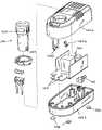
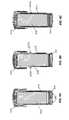
In the illustrated embodiment ofFIGS. 11A-20 , thecharger 400 includes a charger casing orbody 402 having an upper portion402aand alower portion 402b. As shown inFIGS. 11A-20 , thecasing 402 can define abattery chamber 403 and can include anopening 404 for receivingbatteries 200. In the illustrated embodiment, theopening 404 is located generally toward thefront end 406 of thecharger 400. Arear portion 408 of thecharger 400 is provided with anelectrical input receptacle 410 for receiving a cord or plug.
As best shown inFIGS. 11A and 11B , first and second receiving slots418a,418bextend through thecharger casing 402 on opposite sides of theopening 404 and are sized to engage portions of thebattery 200 to retain thebattery 200 in thecharger 400 and to orient thebattery 200 with respect to thecharger 400. In some embodiments, the receiving slots418a,418bare similar in size, shape, and relative orientation to the receiving slots in thebattery chamber 56 of thepower tool 10.
In some embodiments, the receiving slots418a,418bcan be differently sized so that thebattery 200 can only be inserted into thebattery chamber 403 in a required orientation (i.e.,battery terminals 202a,202bengagingrespective terminals 420a,420bof the battery charger400).
In the illustrated embodiment ofFIGS. 11A-20 , the receiving slots418a,418bare generally L-shaped. In this manner, after abattery 200 is inserted axially through theopening 404 and into thebattery chamber 403, thebattery 400 can be pivoted about thebattery axis 201 and relative to thecasing 402 from an unlocked position, in which thebattery 200 is movable axially out of theopening 404, toward a locked position, in which the engagement between thelugs battery 200 from being moved axially out of thebattery chamber 403.
As shown inFIGS. 12 ,13, and15A-16, thecharger 400 can include anindicator 419 located on an outer surface of thecasing 402 and thebattery 200 can include asimilar indicator 223. In this manner, when theindicator 419 of thecharger 400 and theindicator 223 of thebattery 200 are misaligned, the operator will be able to confirm that thebattery 200 is in the unlocked position. Similarly, when theindicator 419 of thecharger 400 and theindicator 223 of thebattery 200 are aligned, the operator will be able to confirm that thebattery 200 is in the locked position.
In embodiments of thecharger 400, such as the illustrated embodiment ofFIGS. 11A-20 , having L-shaped receiving slots418a,418b, theterminals 420a,420bof thebattery charger 400 can extend circumferentially around at least a portion of thebattery chamber 403 so that theterminals 202a,202bcan be electrically connected torespective terminals 420a,420bof thebattery charger 400 when thebattery 200 is in the locked and unlocked positions.
In some such embodiments, thecharger 400 is operable to charge thebattery 200 while thebattery 200 is in either the locked position or the unlocked position. This can be a convenience for operators, some of whom may wish to quickly insert thebattery 200 for charging without having to pivot thebattery 200 toward a locked position. Alternatively, in applications in which thecharger 400 is mounted on a wall or another vertical surface (i.e., sobattery chamber 403 opens in a direction substantially parallel to the ground), operators can insert thebattery 200 into thebattery chamber 403 and pivot thebattery 200 toward the locked position so that thebattery 200 can be charged and so that thebattery 200 does not fall out of thecharger 400 during charging.
As shown inFIG. 14 , thecharger 400 can include mountingreceptacles 428 for mounting thecharger 400 on a wall or other inclined surface, or alternatively, for securing thecharger 400 to a work cart, a horizontal surface, a work table or bench, and the like. In some embodiments, such as the illustrated embodiment ofFIG. 14 , thecharger 400 can also includefeet 430 for supporting thecharger 400.
As shown inFIG. 13 , thecharger 400 can also includedetents 422 for engagement with theprojections 224 on thebattery 200 to provide tactile and/or audible feedback to the operator indicate to the operator that the operator has moved thebattery 200 to the locked position, or alternatively, to the unlocked position. In the illustrated embodiment ofFIGS. 11A-20 , thedetents 422 are elastically deformable and extend horizontally across the lower end of thebattery chamber 403. In other embodiments, thedetents 422 can have other relative orientations and positions. For example, in some embodiments, thedetents 422 can extend circumferentially around the side walls of thebattery chamber 403 for engagement withcorresponding battery projections 224 located on the sides of thebattery 200.
A charge indicator412 (e.g., a light-emitting diode (LED) or another light) can be supported on the upper charger casing402afor displaying charge data to an operator (e.g., charge time remaining, charging in progress, charging complete, etc.). In other embodiments, thecharger 400 can also or alternatively include other indicators or displays.
Operation of the power tool will be discussed with respect toFIGS. 1 ,2 and21.
For operation, an operator grasps thehand grip 16 with a first hand and grasps thebody 14 with a second hand and pivots thehand grip 16 about thepivot axis 34 from the first position (shown inFIG. 1 ) toward the second position (shown inFIG. 2 ).
If the lockingassembly 110 is in the locked position, the operator can move theactuator 114 with respect to thehousing 12 to move the lockingmember 112 from the locked position toward the unlocked position before and/or during pivoting of thebody 14 andhand grip 16. When a desired orientation between thebody 14 and thehand grip 16 is achieved, the operator can insert a tool into thespindle 30.
The operator can also insert thebattery 200 into thebattery chamber 56 to provide power to thepower tool 10. The operator can then move thetrigger 77 toward an operational position, in turn engaging thedirection switch 76. When thetrigger 77 is activated, power is supplied to theelectrical circuit 310 from thebattery 200 and thecontroller 320 wakes from a low power state. Thecontroller 320 in turn takes a state of charge reading from thebattery 200, stores the reading in the controller's internal memory (not shown) and activates thefuel gauge 118 to display the current at rest state of charge of thebattery 200.
Once the at rest battery state of charge has been measured, thecontroller 320 switches the normally non-conducting on/offswitch 330 into the conducting state such that current is supplied from thebattery cell 208 to themotor 28 as determined by thedirectional switch 76, causing themotor 28 to rotate thespindle 30 and the tool element. Thecontroller 320 continues to display the state of charge reading via thefuel gauge 118 until the predetermined time period expires.
The operator can then move thehand grip 16 from the second position back to the first position, or alternatively, to an intermediate position (not shown) to orient thepower tool 10 to operate in a confined workspace and/or to perform a different operation. Alternatively or in addition, an operator may pivot thehand grip 16 about thepivot axis 34 and relative to thebody 14 with a flick of the wrist and/or by grasping one of thehand grip 16 and thebody 14 with one hand and pressing the other of thehand grip 16 and thebody 14 against his body.
In one embodiment, once thetrigger 77 is released, the on/offswitch 330 is positioned in the non-conducting state and thecontroller 320 beings to count down the waiting period. In this embodiment, if the user activates thetrigger 77 prior to the expiration of the waiting period, thecontroller 320 approximates the battery's current state of charge based on the previous state of charge reading and the time duration that themotor 28 was running and displays that approximation. In some constructions, if the time duration that themotor 28 was running is longer than a predetermined time period, thecontroller 320 does not calculate or approximate a current state of charge reading of the battery and does not display any battery state of charge reading on thefuel gauge 118.
If the user activates the trigger subsequent to the expiration of the waiting period, thecontroller 320 takes another at rest battery state of charge reading prior to activation of the on/offswitch 330 and power being supplied to themotor 28, as discussed above.
After operating thepower tool 10 and thebattery 200, the operator can remove thebattery 200 from thepower tool 10 and insert thebattery 200 into thecharger 400 to recharge thebattery 200. In some embodiments, the operator can insert thebattery 200 axially into thebattery chamber 403 of thebattery charger 400 to initiate battery charging. Alternatively or in addition, the operator can pivot thebattery 200 toward a locked position so that thebattery 200 is lockingly secured to thebattery charger 400 during charging.
After charging is completed (e.g., after a predetermined charging time or when charging complete data is displayed on theindicator 412 of the charger400), the operator can remove thebattery 200 from thecharger 400 and insert the newly chargedbattery 200 into thebattery chamber 56 of thepower tool 200. To confirm that thebattery 200 is fully charged, the operator can depress thetrigger 77, causing the state of charge data to be shown on thedisplay 120.
One or more of the above-identified and other independent features and independent advantages are set forth in the following claims.
Claims (9)
1. A method of operating a battery charger having a body and a charging circuit, one of the charger and the battery including an outwardly extending protrusion and an other of the charger and the battery defining a recess for receiving the outwardly extending protrusion, the method comprising the acts of:
electrically connecting the battery and the charging circuit to charge the battery before engaging the protrusion in the recess to secure the battery to the body of the charger,
wherein electrically connecting the battery to the charging circuit includes moving the battery along a first path, and wherein securing the battery to the body includes moving the battery along a second path, the second path being different than the first path.
2. The method ofclaim 1 , wherein the body of the battery charger defines an aperture, and wherein electrically connecting the battery and the charging circuit includes inserting the battery into the aperture along an insertion axis.
3. The method ofclaim 2 , wherein engaging the protrusion in the recess includes pivoting the battery about the axis relative to the battery charger.
4. The method ofclaim 1 , wherein engaging the protrusion in the recess includes moving the battery toward a locked position, in which the battery is secured to the body of the charger, and further comprising moving the battery toward an unlocked position, in which the battery is removably supported on the body, the battery being electrically connected to the charging circuit when the battery is in the locked position and when the battery is in the unlocked position.
5. A method of operating a battery charger having a body and a charging circuit extending through the body, the method comprising the acts of:
electrically connecting the battery to the charging circuit to charge the battery; and
moving the battery with respect to the battery charger to secure the battery to the body while continuing to charge the battery,
wherein electrically connecting the battery to the charging circuit includes moving the battery along a first path, and wherein securing the battery to the body includes moving the battery along a second path, the second path being different than the first path.
6. The method ofclaim 5 , wherein the body of the battery charger defines an aperture, and wherein electrically connecting the battery to the charging circuit includes inserting the battery into the aperture along an insertion axis.
7. The method ofclaim 6 , wherein one of the charger and the battery includes an outwardly extending protrusion, wherein an other of the charger and the battery defines a recess for receiving the outwardly extending protrusion, and wherein moving the battery with respect to the battery charger to secure the battery to the body includes moving the protrusion into locking engagement with the recess.
8. The method ofclaim 6 , wherein moving the battery with respect to the battery charger to secure the battery to the body includes pivoting the battery about the axis.
9. The method ofclaim 5 , wherein moving the battery with respect to the battery charger to secure the battery to the body includes moving the battery toward a locked position, in which the battery is secured to the body of the charger, and further comprising moving the battery toward an unlocked position, in which the battery is removably supported on the body, the battery being electrically connected to the charging circuit when the battery is in the locked position and when the battery is in the unlocked position.
Priority Applications (6)
| Application Number | Priority Date | Filing Date | Title |
|---|---|---|---|
| DE102006023187.2ADE102006023187B4 (en) | 2005-05-17 | 2006-05-17 | Method for operating a battery charger and a combination comprising a battery and a battery charger |
| GB0609769AGB2426391B (en) | 2005-05-17 | 2006-05-17 | Power tool, battery, charger and method of operating the same |
| JP2006138311AJP2006325395A (en) | 2005-05-17 | 2006-05-17 | Power tool, battery, charger, and operating method of these |
| US11/435,640US7557534B2 (en) | 2005-05-17 | 2006-05-17 | Power tool, battery, charger and method of operating the same |
| US11/940,814US7814816B2 (en) | 2005-05-17 | 2007-11-15 | Power tool, battery, charger and method of operating the same |
| US12/340,984US7932695B2 (en) | 2005-05-17 | 2008-12-22 | Power tool, battery, charger and method of operating the same |
Applications Claiming Priority (2)
| Application Number | Priority Date | Filing Date | Title |
|---|---|---|---|
| US68219205P | 2005-05-17 | 2005-05-17 | |
| US11/435,640US7557534B2 (en) | 2005-05-17 | 2006-05-17 | Power tool, battery, charger and method of operating the same |
Related Child Applications (2)
| Application Number | Title | Priority Date | Filing Date |
|---|---|---|---|
| US11/940,814ContinuationUS7814816B2 (en) | 2005-05-17 | 2007-11-15 | Power tool, battery, charger and method of operating the same |
| US12/340,984ContinuationUS7932695B2 (en) | 2005-05-17 | 2008-12-22 | Power tool, battery, charger and method of operating the same |
Publications (2)
| Publication Number | Publication Date |
|---|---|
| US20060267548A1 US20060267548A1 (en) | 2006-11-30 |
| US7557534B2true US7557534B2 (en) | 2009-07-07 |
Family
ID=37462504
Family Applications (3)
| Application Number | Title | Priority Date | Filing Date |
|---|---|---|---|
| US11/435,640Active2027-05-31US7557534B2 (en) | 2005-05-17 | 2006-05-17 | Power tool, battery, charger and method of operating the same |
| US11/940,814ActiveUS7814816B2 (en) | 2005-05-17 | 2007-11-15 | Power tool, battery, charger and method of operating the same |
| US12/340,984ActiveUS7932695B2 (en) | 2005-05-17 | 2008-12-22 | Power tool, battery, charger and method of operating the same |
Family Applications After (2)
| Application Number | Title | Priority Date | Filing Date |
|---|---|---|---|
| US11/940,814ActiveUS7814816B2 (en) | 2005-05-17 | 2007-11-15 | Power tool, battery, charger and method of operating the same |
| US12/340,984ActiveUS7932695B2 (en) | 2005-05-17 | 2008-12-22 | Power tool, battery, charger and method of operating the same |
Country Status (4)
| Country | Link |
|---|---|
| US (3) | US7557534B2 (en) |
| JP (1) | JP2006325395A (en) |
| DE (1) | DE102006023187B4 (en) |
| GB (1) | GB2426391B (en) |
Cited By (21)
| Publication number | Priority date | Publication date | Assignee | Title |
|---|---|---|---|---|
| US20080053716A1 (en)* | 2006-02-09 | 2008-03-06 | Scheucher Karl F | Refuelable battery-powered electric vehicle |
| US20090015195A1 (en)* | 2007-07-04 | 2009-01-15 | Hartmut Loth-Krausser | Device with Electric Appliance and Charging Station |
| US20100031517A1 (en)* | 2008-08-06 | 2010-02-11 | Masatoshi Fukinuki | Handheld reciprocating saw and the operating method thereof |
| USD627204S1 (en)* | 2009-03-23 | 2010-11-16 | Techtronic Power Tools Technology Limited | Battery pack receiving area and connection terminals for a high current draw device |
| US20110030986A1 (en)* | 2009-08-06 | 2011-02-10 | Makita Corporation | Power tools |
| USD632649S1 (en) | 2006-09-29 | 2011-02-15 | Karl F. Scheucher | Cordless power supply |
| US20110266014A1 (en)* | 2010-04-30 | 2011-11-03 | Mcroberts Jason C | Twist-handled power tool with locking system |
| US20130341058A1 (en)* | 2012-06-25 | 2013-12-26 | Robert Bosch Gmbh | Power tool |
| US20140014385A1 (en)* | 2012-07-14 | 2014-01-16 | Hitachi Koki Co., Ltd. | Power tool |
| US8710996B1 (en)* | 2011-12-14 | 2014-04-29 | Jeffrey Bryan Gronneberg | Invisible fence battery charger |
| US20140262391A1 (en)* | 2013-03-13 | 2014-09-18 | Ingersoll-Rand Company | Adapter for Transferring Electrical Signals to Pneumatic Tool |
| US8860377B2 (en) | 2006-02-09 | 2014-10-14 | Karl F. Scheucher | Scalable intelligent power supply system and method |
| US9266230B2 (en) | 2010-01-07 | 2016-02-23 | Black & Decker Inc. | Twist-handled power tool with locking system |
| USD772806S1 (en) | 2014-11-26 | 2016-11-29 | Techtronic Industries Co. Ltd. | Battery |
| US20170264224A1 (en)* | 2016-03-11 | 2017-09-14 | Dometic Sweden Ab | Power Wand and Method of Use |
| USD893436S1 (en) | 2016-11-17 | 2020-08-18 | Dometic Sweden Ab | Power wand |
| US10971966B2 (en) | 2018-05-14 | 2021-04-06 | Black & Decker Inc. | Power tool with partition assembly between transmission and motor |
| US20210362289A1 (en)* | 2018-09-14 | 2021-11-25 | Koki Holdings Co., Ltd. | Electric work machine |
| WO2023079091A1 (en)* | 2021-11-08 | 2023-05-11 | Wahl Gmbh | Hair-cutting device, charger, and rechargeable battery |
| US11813729B2 (en) | 2018-05-14 | 2023-11-14 | Black & Decker Inc. | Power tool with partition assembly between transmission and motor |
| US20240072357A1 (en)* | 2022-08-26 | 2024-02-29 | Qingdao Activa Shade Inc. | Umbrella hub and battery pack assembly |
Families Citing this family (485)
| Publication number | Priority date | Publication date | Assignee | Title |
|---|---|---|---|---|
| US20070084897A1 (en) | 2003-05-20 | 2007-04-19 | Shelton Frederick E Iv | Articulating surgical stapling instrument incorporating a two-piece e-beam firing mechanism |
| US9060770B2 (en) | 2003-05-20 | 2015-06-23 | Ethicon Endo-Surgery, Inc. | Robotically-driven surgical instrument with E-beam driver |
| US10105140B2 (en)* | 2009-11-20 | 2018-10-23 | Covidien Lp | Surgical console and hand-held surgical device |
| US11890012B2 (en) | 2004-07-28 | 2024-02-06 | Cilag Gmbh International | Staple cartridge comprising cartridge body and attached support |
| US8215531B2 (en) | 2004-07-28 | 2012-07-10 | Ethicon Endo-Surgery, Inc. | Surgical stapling instrument having a medical substance dispenser |
| US9072535B2 (en) | 2011-05-27 | 2015-07-07 | Ethicon Endo-Surgery, Inc. | Surgical stapling instruments with rotatable staple deployment arrangements |
| US11998198B2 (en) | 2004-07-28 | 2024-06-04 | Cilag Gmbh International | Surgical stapling instrument incorporating a two-piece E-beam firing mechanism |
| DE102006023187B4 (en)* | 2005-05-17 | 2020-02-27 | Milwaukee Electric Tool Corp. | Method for operating a battery charger and a combination comprising a battery and a battery charger |
| US10159482B2 (en) | 2005-08-31 | 2018-12-25 | Ethicon Llc | Fastener cartridge assembly comprising a fixed anvil and different staple heights |
| US9237891B2 (en) | 2005-08-31 | 2016-01-19 | Ethicon Endo-Surgery, Inc. | Robotically-controlled surgical stapling devices that produce formed staples having different lengths |
| US11484312B2 (en) | 2005-08-31 | 2022-11-01 | Cilag Gmbh International | Staple cartridge comprising a staple driver arrangement |
| US11246590B2 (en) | 2005-08-31 | 2022-02-15 | Cilag Gmbh International | Staple cartridge including staple drivers having different unfired heights |
| US7934630B2 (en) | 2005-08-31 | 2011-05-03 | Ethicon Endo-Surgery, Inc. | Staple cartridges for forming staples having differing formed staple heights |
| US7669746B2 (en) | 2005-08-31 | 2010-03-02 | Ethicon Endo-Surgery, Inc. | Staple cartridges for forming staples having differing formed staple heights |
| CN101300732B (en) | 2005-11-04 | 2011-02-23 | 罗伯特·博世有限公司 | Drill with solid state speed control and method of operating |
| US20070106317A1 (en) | 2005-11-09 | 2007-05-10 | Shelton Frederick E Iv | Hydraulically and electrically actuated articulation joints for surgical instruments |
| US8186555B2 (en) | 2006-01-31 | 2012-05-29 | Ethicon Endo-Surgery, Inc. | Motor-driven surgical cutting and fastening instrument with mechanical closure system |
| US20110024477A1 (en) | 2009-02-06 | 2011-02-03 | Hall Steven G | Driven Surgical Stapler Improvements |
| US7753904B2 (en) | 2006-01-31 | 2010-07-13 | Ethicon Endo-Surgery, Inc. | Endoscopic surgical instrument with a handle that can articulate with respect to the shaft |
| US8820603B2 (en) | 2006-01-31 | 2014-09-02 | Ethicon Endo-Surgery, Inc. | Accessing data stored in a memory of a surgical instrument |
| US20120292367A1 (en) | 2006-01-31 | 2012-11-22 | Ethicon Endo-Surgery, Inc. | Robotically-controlled end effector |
| US11224427B2 (en) | 2006-01-31 | 2022-01-18 | Cilag Gmbh International | Surgical stapling system including a console and retraction assembly |
| US11278279B2 (en) | 2006-01-31 | 2022-03-22 | Cilag Gmbh International | Surgical instrument assembly |
| US7845537B2 (en) | 2006-01-31 | 2010-12-07 | Ethicon Endo-Surgery, Inc. | Surgical instrument having recording capabilities |
| US8708213B2 (en) | 2006-01-31 | 2014-04-29 | Ethicon Endo-Surgery, Inc. | Surgical instrument having a feedback system |
| US11793518B2 (en) | 2006-01-31 | 2023-10-24 | Cilag Gmbh International | Powered surgical instruments with firing system lockout arrangements |
| US20110295295A1 (en) | 2006-01-31 | 2011-12-01 | Ethicon Endo-Surgery, Inc. | Robotically-controlled surgical instrument having recording capabilities |
| US8992422B2 (en) | 2006-03-23 | 2015-03-31 | Ethicon Endo-Surgery, Inc. | Robotically-controlled endoscopic accessory channel |
| US7619387B2 (en)* | 2006-05-08 | 2009-11-17 | Ingersoll-Rand Company | Battery pack attachment arrangement |
| US8322455B2 (en) | 2006-06-27 | 2012-12-04 | Ethicon Endo-Surgery, Inc. | Manually driven surgical cutting and fastening instrument |
| US10568652B2 (en) | 2006-09-29 | 2020-02-25 | Ethicon Llc | Surgical staples having attached drivers of different heights and stapling instruments for deploying the same |
| US7506791B2 (en) | 2006-09-29 | 2009-03-24 | Ethicon Endo-Surgery, Inc. | Surgical stapling instrument with mechanical mechanism for limiting maximum tissue compression |
| US11980366B2 (en) | 2006-10-03 | 2024-05-14 | Cilag Gmbh International | Surgical instrument |
| US7779931B2 (en)* | 2006-11-10 | 2010-08-24 | Joel Townsan | Electric hand screwdriver with adjustable head |
| US8652120B2 (en) | 2007-01-10 | 2014-02-18 | Ethicon Endo-Surgery, Inc. | Surgical instrument with wireless communication between control unit and sensor transponders |
| US11291441B2 (en) | 2007-01-10 | 2022-04-05 | Cilag Gmbh International | Surgical instrument with wireless communication between control unit and remote sensor |
| US8684253B2 (en) | 2007-01-10 | 2014-04-01 | Ethicon Endo-Surgery, Inc. | Surgical instrument with wireless communication between a control unit of a robotic system and remote sensor |
| US8632535B2 (en) | 2007-01-10 | 2014-01-21 | Ethicon Endo-Surgery, Inc. | Interlock and surgical instrument including same |
| US11039836B2 (en) | 2007-01-11 | 2021-06-22 | Cilag Gmbh International | Staple cartridge for use with a surgical stapling instrument |
| US20080169333A1 (en) | 2007-01-11 | 2008-07-17 | Shelton Frederick E | Surgical stapler end effector with tapered distal end |
| US7673782B2 (en) | 2007-03-15 | 2010-03-09 | Ethicon Endo-Surgery, Inc. | Surgical stapling instrument having a releasable buttress material |
| US8893946B2 (en) | 2007-03-28 | 2014-11-25 | Ethicon Endo-Surgery, Inc. | Laparoscopic tissue thickness and clamp load measuring devices |
| US11564682B2 (en) | 2007-06-04 | 2023-01-31 | Cilag Gmbh International | Surgical stapler device |
| US8931682B2 (en) | 2007-06-04 | 2015-01-13 | Ethicon Endo-Surgery, Inc. | Robotically-controlled shaft based rotary drive systems for surgical instruments |
| US7753245B2 (en) | 2007-06-22 | 2010-07-13 | Ethicon Endo-Surgery, Inc. | Surgical stapling instruments |
| US11849941B2 (en) | 2007-06-29 | 2023-12-26 | Cilag Gmbh International | Staple cartridge having staple cavities extending at a transverse angle relative to a longitudinal cartridge axis |
| US7999507B2 (en)* | 2007-12-10 | 2011-08-16 | Illinois Tool Works Inc. | Power tool having mating battery terminals |
| DE102007060057A1 (en)* | 2007-12-13 | 2009-06-18 | Robert Bosch Gmbh | Hand tool |
| US8806491B2 (en) | 2007-12-31 | 2014-08-12 | Intel Corporation | Thread migration to improve power efficiency in a parallel processing environment |
| US8636736B2 (en) | 2008-02-14 | 2014-01-28 | Ethicon Endo-Surgery, Inc. | Motorized surgical cutting and fastening instrument |
| US7866527B2 (en) | 2008-02-14 | 2011-01-11 | Ethicon Endo-Surgery, Inc. | Surgical stapling apparatus with interlockable firing system |
| US7819298B2 (en) | 2008-02-14 | 2010-10-26 | Ethicon Endo-Surgery, Inc. | Surgical stapling apparatus with control features operable with one hand |
| US9179912B2 (en) | 2008-02-14 | 2015-11-10 | Ethicon Endo-Surgery, Inc. | Robotically-controlled motorized surgical cutting and fastening instrument |
| US11986183B2 (en) | 2008-02-14 | 2024-05-21 | Cilag Gmbh International | Surgical cutting and fastening instrument comprising a plurality of sensors to measure an electrical parameter |
| US8573465B2 (en) | 2008-02-14 | 2013-11-05 | Ethicon Endo-Surgery, Inc. | Robotically-controlled surgical end effector system with rotary actuated closure systems |
| US8758391B2 (en) | 2008-02-14 | 2014-06-24 | Ethicon Endo-Surgery, Inc. | Interchangeable tools for surgical instruments |
| JP5410110B2 (en) | 2008-02-14 | 2014-02-05 | エシコン・エンド−サージェリィ・インコーポレイテッド | Surgical cutting / fixing instrument with RF electrode |
| US9585657B2 (en) | 2008-02-15 | 2017-03-07 | Ethicon Endo-Surgery, Llc | Actuator for releasing a layer of material from a surgical end effector |
| US11272927B2 (en) | 2008-02-15 | 2022-03-15 | Cilag Gmbh International | Layer arrangements for surgical staple cartridges |
| US8210411B2 (en) | 2008-09-23 | 2012-07-03 | Ethicon Endo-Surgery, Inc. | Motor-driven surgical cutting instrument |
| US9386983B2 (en) | 2008-09-23 | 2016-07-12 | Ethicon Endo-Surgery, Llc | Robotically-controlled motorized surgical instrument |
| US9005230B2 (en) | 2008-09-23 | 2015-04-14 | Ethicon Endo-Surgery, Inc. | Motorized surgical instrument |
| US11648005B2 (en) | 2008-09-23 | 2023-05-16 | Cilag Gmbh International | Robotically-controlled motorized surgical instrument with an end effector |
| US8608045B2 (en) | 2008-10-10 | 2013-12-17 | Ethicon Endo-Sugery, Inc. | Powered surgical cutting and stapling apparatus with manually retractable firing system |
| CN101722505B (en)* | 2008-10-27 | 2014-12-10 | 南京德朔实业有限公司 | Power tool |
| JP4961418B2 (en)* | 2008-12-26 | 2012-06-27 | オムロン株式会社 | Electric tool |
| US8517239B2 (en) | 2009-02-05 | 2013-08-27 | Ethicon Endo-Surgery, Inc. | Surgical stapling instrument comprising a magnetic element driver |
| US8444036B2 (en) | 2009-02-06 | 2013-05-21 | Ethicon Endo-Surgery, Inc. | Motor driven surgical fastener device with mechanisms for adjusting a tissue gap within the end effector |
| RU2525225C2 (en) | 2009-02-06 | 2014-08-10 | Этикон Эндо-Серджери, Инк. | Improvement of drive surgical suturing instrument |
| CN101872848A (en)* | 2009-04-24 | 2010-10-27 | 鸿富锦精密工业(深圳)有限公司 | Battery box and electronic device using the battery box |
| CN101872849B (en)* | 2009-04-27 | 2013-11-06 | 鸿富锦精密工业(深圳)有限公司 | Battery box and electronic device adopting same |
| FR2947201B1 (en)* | 2009-06-26 | 2015-03-13 | Renault Georges Ets | ELECTROPORTATIVE SCREWING TOOL INCLUDING RECHARGEABLE ELECTRICAL BATTERY ORIENTED ERGONOMICALLY |
| EP2289670B1 (en)* | 2009-08-31 | 2012-07-11 | Robert Bosch GmbH | Rotary power tool |
| US8179276B2 (en)* | 2009-09-29 | 2012-05-15 | Tyco Healthcare Group Lp | Battery assembly with alarm |
| WO2011087542A2 (en)* | 2009-10-23 | 2011-07-21 | California Institute Of Technology | Percussive augmenter of rotary drills for operating as a rotary-hammer drill |
| CN102049762B (en)* | 2009-10-28 | 2012-08-22 | 南京德朔实业有限公司 | Electric hammer |
| CN201565933U (en)* | 2009-10-30 | 2010-09-01 | 南京德朔实业有限公司 | Electric hammer |
| JP5368946B2 (en)* | 2009-11-16 | 2013-12-18 | 株式会社マキタ | Electric tool |
| US8220688B2 (en) | 2009-12-24 | 2012-07-17 | Ethicon Endo-Surgery, Inc. | Motor-driven surgical cutting instrument with electric actuator directional control assembly |
| US8851354B2 (en) | 2009-12-24 | 2014-10-07 | Ethicon Endo-Surgery, Inc. | Surgical cutting instrument that analyzes tissue thickness |
| US20220362467A1 (en)* | 2010-02-05 | 2022-11-17 | Deka Products Limited Partnership | Devices methods and systems for wireless control of medical devices |
| JP5461221B2 (en) | 2010-02-12 | 2014-04-02 | 株式会社マキタ | Electric tool powered by multiple battery packs |
| EP3756834B1 (en)* | 2010-07-02 | 2021-12-08 | Husqvarna Ab | Battery powered tool |
| US8783543B2 (en) | 2010-07-30 | 2014-07-22 | Ethicon Endo-Surgery, Inc. | Tissue acquisition arrangements and methods for surgical stapling devices |
| DE102010039794A1 (en)* | 2010-08-26 | 2012-03-01 | Robert Bosch Gmbh | Hand machine tool device |
| US10945731B2 (en) | 2010-09-30 | 2021-03-16 | Ethicon Llc | Tissue thickness compensator comprising controlled release and expansion |
| US9232941B2 (en) | 2010-09-30 | 2016-01-12 | Ethicon Endo-Surgery, Inc. | Tissue thickness compensator comprising a reservoir |
| US9016542B2 (en) | 2010-09-30 | 2015-04-28 | Ethicon Endo-Surgery, Inc. | Staple cartridge comprising compressible distortion resistant components |
| US11925354B2 (en) | 2010-09-30 | 2024-03-12 | Cilag Gmbh International | Staple cartridge comprising staples positioned within a compressible portion thereof |
| US9788834B2 (en) | 2010-09-30 | 2017-10-17 | Ethicon Llc | Layer comprising deployable attachment members |
| US12213666B2 (en) | 2010-09-30 | 2025-02-04 | Cilag Gmbh International | Tissue thickness compensator comprising layers |
| US11298125B2 (en) | 2010-09-30 | 2022-04-12 | Cilag Gmbh International | Tissue stapler having a thickness compensator |
| US9386988B2 (en) | 2010-09-30 | 2016-07-12 | Ethicon End-Surgery, LLC | Retainer assembly including a tissue thickness compensator |
| US9351730B2 (en) | 2011-04-29 | 2016-05-31 | Ethicon Endo-Surgery, Llc | Tissue thickness compensator comprising channels |
| US9364233B2 (en) | 2010-09-30 | 2016-06-14 | Ethicon Endo-Surgery, Llc | Tissue thickness compensators for circular surgical staplers |
| US11812965B2 (en) | 2010-09-30 | 2023-11-14 | Cilag Gmbh International | Layer of material for a surgical end effector |
| US9629814B2 (en) | 2010-09-30 | 2017-04-25 | Ethicon Endo-Surgery, Llc | Tissue thickness compensator configured to redistribute compressive forces |
| US8695866B2 (en) | 2010-10-01 | 2014-04-15 | Ethicon Endo-Surgery, Inc. | Surgical instrument having a power control circuit |
| DE102010063069A1 (en)* | 2010-12-14 | 2012-06-14 | Robert Bosch Gmbh | Hand tool, in particular drill or Schraubbohrmaschine |
| US9120213B2 (en) | 2011-01-21 | 2015-09-01 | Milwaukee Electric Tool Corporation | Powered ratchet wrench |
| FR2971180B1 (en)* | 2011-02-09 | 2013-02-15 | Georges Renault | PORTABLE TURNING MOTORIZED TOOL WITH ACTUATING MEANS INCLUDING A SWIVELING LEVER THROUGH ONE OF ITS ENDS |
| AU2012250197B2 (en) | 2011-04-29 | 2017-08-10 | Ethicon Endo-Surgery, Inc. | Staple cartridge comprising staples positioned within a compressible portion thereof |
| US11207064B2 (en) | 2011-05-27 | 2021-12-28 | Cilag Gmbh International | Automated end effector component reloading system for use with a robotic system |
| DE102011078082B4 (en)* | 2011-06-27 | 2022-08-11 | Robert Bosch Gmbh | Hand tool machine, in particular drilling or screwing device |
| US9077053B2 (en)* | 2011-07-20 | 2015-07-07 | Milwaukee Electric Tool Corporation | Battery charger including multiple charging ports on surfaces forming an apex |
| EP2747948B1 (en)* | 2011-08-26 | 2018-05-09 | Husqvarna AB | Guide and control assembly |
| US8864476B2 (en)* | 2011-08-31 | 2014-10-21 | Flow Control Llc. | Portable battery operated bilge pump |
| TW201332725A (en)* | 2012-02-10 | 2013-08-16 | Master Air Tool Co Ltd | Pneumatic tool head structure |
| US9044230B2 (en) | 2012-02-13 | 2015-06-02 | Ethicon Endo-Surgery, Inc. | Surgical cutting and fastening instrument with apparatus for determining cartridge and firing motion status |
| BR112014024098B1 (en) | 2012-03-28 | 2021-05-25 | Ethicon Endo-Surgery, Inc. | staple cartridge |
| MX358135B (en) | 2012-03-28 | 2018-08-06 | Ethicon Endo Surgery Inc | Tissue thickness compensator comprising a plurality of layers. |
| JP6224070B2 (en) | 2012-03-28 | 2017-11-01 | エシコン・エンド−サージェリィ・インコーポレイテッドEthicon Endo−Surgery,Inc. | Retainer assembly including tissue thickness compensator |
| WO2013167666A2 (en)* | 2012-05-09 | 2013-11-14 | The Blade Saver Company Limited | A safety razor blade sharpening device and assembly |
| US9101358B2 (en) | 2012-06-15 | 2015-08-11 | Ethicon Endo-Surgery, Inc. | Articulatable surgical instrument comprising a firing drive |
| US20140001231A1 (en) | 2012-06-28 | 2014-01-02 | Ethicon Endo-Surgery, Inc. | Firing system lockout arrangements for surgical instruments |
| US20140005718A1 (en) | 2012-06-28 | 2014-01-02 | Ethicon Endo-Surgery, Inc. | Multi-functional powered surgical device with external dissection features |
| US9289256B2 (en) | 2012-06-28 | 2016-03-22 | Ethicon Endo-Surgery, Llc | Surgical end effectors having angled tissue-contacting surfaces |
| US9408606B2 (en) | 2012-06-28 | 2016-08-09 | Ethicon Endo-Surgery, Llc | Robotically powered surgical device with manually-actuatable reversing system |
| US12383267B2 (en) | 2012-06-28 | 2025-08-12 | Cilag Gmbh International | Robotically powered surgical device with manually-actuatable reversing system |
| US9282974B2 (en) | 2012-06-28 | 2016-03-15 | Ethicon Endo-Surgery, Llc | Empty clip cartridge lockout |
| US11278284B2 (en) | 2012-06-28 | 2022-03-22 | Cilag Gmbh International | Rotary drive arrangements for surgical instruments |
| BR112014032776B1 (en) | 2012-06-28 | 2021-09-08 | Ethicon Endo-Surgery, Inc | SURGICAL INSTRUMENT SYSTEM AND SURGICAL KIT FOR USE WITH A SURGICAL INSTRUMENT SYSTEM |
| JP6290201B2 (en) | 2012-06-28 | 2018-03-07 | エシコン・エンド−サージェリィ・インコーポレイテッドEthicon Endo−Surgery,Inc. | Lockout for empty clip cartridge |
| JP5892382B2 (en)* | 2012-07-30 | 2016-03-23 | 日立工機株式会社 | Electric tool |
| KR101979786B1 (en)* | 2012-11-12 | 2019-05-17 | 삼성전자 주식회사 | Processing Method of a battery state and Electronic Device supporting the same |
| US20140139344A1 (en)* | 2012-11-19 | 2014-05-22 | Snap-On Incorporated | Warning light devices and methods |
| US9144895B2 (en)* | 2013-01-10 | 2015-09-29 | Kevin Patrick Kearney | Motorized casket/coffin key/crank |
| BR112015021082B1 (en) | 2013-03-01 | 2022-05-10 | Ethicon Endo-Surgery, Inc | surgical instrument |
| RU2672520C2 (en) | 2013-03-01 | 2018-11-15 | Этикон Эндо-Серджери, Инк. | Hingedly turnable surgical instruments with conducting ways for signal transfer |
| US9539043B2 (en) | 2013-03-13 | 2017-01-10 | Ebi, Llc | Screw driver, combination, and related methods |
| US9629629B2 (en) | 2013-03-14 | 2017-04-25 | Ethicon Endo-Surgey, LLC | Control systems for surgical instruments |
| US9808244B2 (en) | 2013-03-14 | 2017-11-07 | Ethicon Llc | Sensor arrangements for absolute positioning system for surgical instruments |
| WO2014144353A1 (en) | 2013-03-15 | 2014-09-18 | Milwaukee Electric Tool Corporation | Power tool operation recording and playback |
| BR112015026109B1 (en) | 2013-04-16 | 2022-02-22 | Ethicon Endo-Surgery, Inc | surgical instrument |
| US9826976B2 (en) | 2013-04-16 | 2017-11-28 | Ethicon Llc | Motor driven surgical instruments with lockable dual drive shafts |
| DE102013215821A1 (en)* | 2013-08-09 | 2015-02-12 | Robert Bosch Gmbh | Hand tool with an electric motor drive as a direct drive |
| MX369362B (en) | 2013-08-23 | 2019-11-06 | Ethicon Endo Surgery Llc | Firing member retraction devices for powered surgical instruments. |
| US9775609B2 (en) | 2013-08-23 | 2017-10-03 | Ethicon Llc | Tamper proof circuit for surgical instrument battery pack |
| JP1519960S (en)* | 2013-09-17 | 2015-03-23 | ||
| US9962161B2 (en) | 2014-02-12 | 2018-05-08 | Ethicon Llc | Deliverable surgical instrument |
| JP6462004B2 (en) | 2014-02-24 | 2019-01-30 | エシコン エルエルシー | Fastening system with launcher lockout |
| US10004497B2 (en) | 2014-03-26 | 2018-06-26 | Ethicon Llc | Interface systems for use with surgical instruments |
| US20150272580A1 (en) | 2014-03-26 | 2015-10-01 | Ethicon Endo-Surgery, Inc. | Verification of number of battery exchanges/procedure count |
| US10013049B2 (en) | 2014-03-26 | 2018-07-03 | Ethicon Llc | Power management through sleep options of segmented circuit and wake up control |
| US12232723B2 (en) | 2014-03-26 | 2025-02-25 | Cilag Gmbh International | Systems and methods for controlling a segmented circuit |
| BR112016021943B1 (en) | 2014-03-26 | 2022-06-14 | Ethicon Endo-Surgery, Llc | SURGICAL INSTRUMENT FOR USE BY AN OPERATOR IN A SURGICAL PROCEDURE |
| BR112016023825B1 (en) | 2014-04-16 | 2022-08-02 | Ethicon Endo-Surgery, Llc | STAPLE CARTRIDGE FOR USE WITH A SURGICAL STAPLER AND STAPLE CARTRIDGE FOR USE WITH A SURGICAL INSTRUMENT |
| CN106456176B (en) | 2014-04-16 | 2019-06-28 | 伊西康内外科有限责任公司 | Fastener Cartridge Including Extensions With Different Configurations |
| US10327764B2 (en) | 2014-09-26 | 2019-06-25 | Ethicon Llc | Method for creating a flexible staple line |
| CN106456159B (en) | 2014-04-16 | 2019-03-08 | 伊西康内外科有限责任公司 | Fastener Cartridge Assembly and Nail Retainer Cover Arrangement |
| US10470768B2 (en) | 2014-04-16 | 2019-11-12 | Ethicon Llc | Fastener cartridge including a layer attached thereto |
| US20150297225A1 (en) | 2014-04-16 | 2015-10-22 | Ethicon Endo-Surgery, Inc. | Fastener cartridges including extensions having different configurations |
| DE102014211046A1 (en)* | 2014-06-10 | 2015-12-17 | Robert Bosch Gmbh | System comprising at least one electronically commutated electric motor of a defined size and a rechargeable battery of at least one voltage class |
| CN105328623B (en)* | 2014-06-30 | 2017-04-19 | 南京德朔实业有限公司 | Electric tool |
| US10135242B2 (en) | 2014-09-05 | 2018-11-20 | Ethicon Llc | Smart cartridge wake up operation and data retention |
| US11311294B2 (en) | 2014-09-05 | 2022-04-26 | Cilag Gmbh International | Powered medical device including measurement of closure state of jaws |
| BR112017004361B1 (en) | 2014-09-05 | 2023-04-11 | Ethicon Llc | ELECTRONIC SYSTEM FOR A SURGICAL INSTRUMENT |
| DE102014218122A1 (en)* | 2014-09-10 | 2016-03-10 | Robert Bosch Gmbh | Battery-powered hand tool machine with at least one motor housing part |
| US10105142B2 (en) | 2014-09-18 | 2018-10-23 | Ethicon Llc | Surgical stapler with plurality of cutting elements |
| US11523821B2 (en) | 2014-09-26 | 2022-12-13 | Cilag Gmbh International | Method for creating a flexible staple line |
| CN107427300B (en) | 2014-09-26 | 2020-12-04 | 伊西康有限责任公司 | Surgical suture buttresses and auxiliary materials |
| US9721077B1 (en)* | 2014-10-03 | 2017-08-01 | Isaac S. Daniel | Secure electronic charger case for mobile communication devices |
| US10076325B2 (en) | 2014-10-13 | 2018-09-18 | Ethicon Llc | Surgical stapling apparatus comprising a tissue stop |
| US9924944B2 (en) | 2014-10-16 | 2018-03-27 | Ethicon Llc | Staple cartridge comprising an adjunct material |
| US10517594B2 (en) | 2014-10-29 | 2019-12-31 | Ethicon Llc | Cartridge assemblies for surgical staplers |
| US11141153B2 (en) | 2014-10-29 | 2021-10-12 | Cilag Gmbh International | Staple cartridges comprising driver arrangements |
| US9844376B2 (en) | 2014-11-06 | 2017-12-19 | Ethicon Llc | Staple cartridge comprising a releasable adjunct material |
| US10736636B2 (en) | 2014-12-10 | 2020-08-11 | Ethicon Llc | Articulatable surgical instrument system |
| US9943309B2 (en) | 2014-12-18 | 2018-04-17 | Ethicon Llc | Surgical instruments with articulatable end effectors and movable firing beam support arrangements |
| US10188385B2 (en) | 2014-12-18 | 2019-01-29 | Ethicon Llc | Surgical instrument system comprising lockable systems |
| US9844374B2 (en) | 2014-12-18 | 2017-12-19 | Ethicon Llc | Surgical instrument systems comprising an articulatable end effector and means for adjusting the firing stroke of a firing member |
| US10085748B2 (en) | 2014-12-18 | 2018-10-02 | Ethicon Llc | Locking arrangements for detachable shaft assemblies with articulatable surgical end effectors |
| US9987000B2 (en) | 2014-12-18 | 2018-06-05 | Ethicon Llc | Surgical instrument assembly comprising a flexible articulation system |
| MX389118B (en) | 2014-12-18 | 2025-03-20 | Ethicon Llc | SURGICAL INSTRUMENT WITH AN ANVIL THAT CAN BE SELECTIVELY MOVED ON A DISCRETE, NON-MOBILE AXIS RELATIVE TO A STAPLE CARTRIDGE. |
| US9844375B2 (en) | 2014-12-18 | 2017-12-19 | Ethicon Llc | Drive arrangements for articulatable surgical instruments |
| US10159483B2 (en)* | 2015-02-27 | 2018-12-25 | Ethicon Llc | Surgical apparatus configured to track an end-of-life parameter |
| US10180463B2 (en) | 2015-02-27 | 2019-01-15 | Ethicon Llc | Surgical apparatus configured to assess whether a performance parameter of the surgical apparatus is within an acceptable performance band |
| US11154301B2 (en) | 2015-02-27 | 2021-10-26 | Cilag Gmbh International | Modular stapling assembly |
| JP6772165B2 (en)* | 2015-02-27 | 2020-10-21 | エシコン エルエルシーEthicon LLC | Surgical charging system for charging and / or adjusting one or more batteries |
| US9993258B2 (en)* | 2015-02-27 | 2018-06-12 | Ethicon Llc | Adaptable surgical instrument handle |
| US10548504B2 (en) | 2015-03-06 | 2020-02-04 | Ethicon Llc | Overlaid multi sensor radio frequency (RF) electrode system to measure tissue compression |
| US9808246B2 (en) | 2015-03-06 | 2017-11-07 | Ethicon Endo-Surgery, Llc | Method of operating a powered surgical instrument |
| US10617412B2 (en) | 2015-03-06 | 2020-04-14 | Ethicon Llc | System for detecting the mis-insertion of a staple cartridge into a surgical stapler |
| US10441279B2 (en) | 2015-03-06 | 2019-10-15 | Ethicon Llc | Multiple level thresholds to modify operation of powered surgical instruments |
| US9901342B2 (en) | 2015-03-06 | 2018-02-27 | Ethicon Endo-Surgery, Llc | Signal and power communication system positioned on a rotatable shaft |
| JP2020121162A (en) | 2015-03-06 | 2020-08-13 | エシコン エルエルシーEthicon LLC | Time dependent evaluation of sensor data to determine stability element, creep element and viscoelastic element of measurement |
| US9993248B2 (en) | 2015-03-06 | 2018-06-12 | Ethicon Endo-Surgery, Llc | Smart sensors with local signal processing |
| US10245033B2 (en) | 2015-03-06 | 2019-04-02 | Ethicon Llc | Surgical instrument comprising a lockable battery housing |
| US9924961B2 (en) | 2015-03-06 | 2018-03-27 | Ethicon Endo-Surgery, Llc | Interactive feedback system for powered surgical instruments |
| US10687806B2 (en) | 2015-03-06 | 2020-06-23 | Ethicon Llc | Adaptive tissue compression techniques to adjust closure rates for multiple tissue types |
| US10433844B2 (en) | 2015-03-31 | 2019-10-08 | Ethicon Llc | Surgical instrument with selectively disengageable threaded drive systems |
| US10835249B2 (en) | 2015-08-17 | 2020-11-17 | Ethicon Llc | Implantable layers for a surgical instrument |
| US10238386B2 (en) | 2015-09-23 | 2019-03-26 | Ethicon Llc | Surgical stapler having motor control based on an electrical parameter related to a motor current |
| US10327769B2 (en) | 2015-09-23 | 2019-06-25 | Ethicon Llc | Surgical stapler having motor control based on a drive system component |
| US10363036B2 (en) | 2015-09-23 | 2019-07-30 | Ethicon Llc | Surgical stapler having force-based motor control |
| US10105139B2 (en) | 2015-09-23 | 2018-10-23 | Ethicon Llc | Surgical stapler having downstream current-based motor control |
| US10299878B2 (en) | 2015-09-25 | 2019-05-28 | Ethicon Llc | Implantable adjunct systems for determining adjunct skew |
| US10478188B2 (en) | 2015-09-30 | 2019-11-19 | Ethicon Llc | Implantable layer comprising a constricted configuration |
| US10433846B2 (en) | 2015-09-30 | 2019-10-08 | Ethicon Llc | Compressible adjunct with crossing spacer fibers |
| US11890015B2 (en) | 2015-09-30 | 2024-02-06 | Cilag Gmbh International | Compressible adjunct with crossing spacer fibers |
| US10980539B2 (en) | 2015-09-30 | 2021-04-20 | Ethicon Llc | Implantable adjunct comprising bonded layers |
| CN108352474B (en) | 2015-10-30 | 2021-01-19 | 株式会社村田制作所 | Battery pack, electrical device, and charging device |
| US10292704B2 (en) | 2015-12-30 | 2019-05-21 | Ethicon Llc | Mechanisms for compensating for battery pack failure in powered surgical instruments |
| US10368865B2 (en) | 2015-12-30 | 2019-08-06 | Ethicon Llc | Mechanisms for compensating for drivetrain failure in powered surgical instruments |
| US10265068B2 (en) | 2015-12-30 | 2019-04-23 | Ethicon Llc | Surgical instruments with separable motors and motor control circuits |
| BR112018016098B1 (en) | 2016-02-09 | 2023-02-23 | Ethicon Llc | SURGICAL INSTRUMENT |
| US11213293B2 (en) | 2016-02-09 | 2022-01-04 | Cilag Gmbh International | Articulatable surgical instruments with single articulation link arrangements |
| US10413291B2 (en) | 2016-02-09 | 2019-09-17 | Ethicon Llc | Surgical instrument articulation mechanism with slotted secondary constraint |
| US10448948B2 (en) | 2016-02-12 | 2019-10-22 | Ethicon Llc | Mechanisms for compensating for drivetrain failure in powered surgical instruments |
| US11224426B2 (en) | 2016-02-12 | 2022-01-18 | Cilag Gmbh International | Mechanisms for compensating for drivetrain failure in powered surgical instruments |
| US10258331B2 (en) | 2016-02-12 | 2019-04-16 | Ethicon Llc | Mechanisms for compensating for drivetrain failure in powered surgical instruments |
| US10617413B2 (en) | 2016-04-01 | 2020-04-14 | Ethicon Llc | Closure system arrangements for surgical cutting and stapling devices with separate and distinct firing shafts |
| US10413297B2 (en) | 2016-04-01 | 2019-09-17 | Ethicon Llc | Surgical stapling system configured to apply annular rows of staples having different heights |
| US11607239B2 (en) | 2016-04-15 | 2023-03-21 | Cilag Gmbh International | Systems and methods for controlling a surgical stapling and cutting instrument |
| US10426467B2 (en) | 2016-04-15 | 2019-10-01 | Ethicon Llc | Surgical instrument with detection sensors |
| US10492783B2 (en) | 2016-04-15 | 2019-12-03 | Ethicon, Llc | Surgical instrument with improved stop/start control during a firing motion |
| US10828028B2 (en) | 2016-04-15 | 2020-11-10 | Ethicon Llc | Surgical instrument with multiple program responses during a firing motion |
| US10357247B2 (en) | 2016-04-15 | 2019-07-23 | Ethicon Llc | Surgical instrument with multiple program responses during a firing motion |
| US10335145B2 (en) | 2016-04-15 | 2019-07-02 | Ethicon Llc | Modular surgical instrument with configurable operating mode |
| US11179150B2 (en) | 2016-04-15 | 2021-11-23 | Cilag Gmbh International | Systems and methods for controlling a surgical stapling and cutting instrument |
| US10405859B2 (en) | 2016-04-15 | 2019-09-10 | Ethicon Llc | Surgical instrument with adjustable stop/start control during a firing motion |
| US10456137B2 (en) | 2016-04-15 | 2019-10-29 | Ethicon Llc | Staple formation detection mechanisms |
| US10363037B2 (en) | 2016-04-18 | 2019-07-30 | Ethicon Llc | Surgical instrument system comprising a magnetic lockout |
| US20170296173A1 (en) | 2016-04-18 | 2017-10-19 | Ethicon Endo-Surgery, Llc | Method for operating a surgical instrument |
| US11317917B2 (en) | 2016-04-18 | 2022-05-03 | Cilag Gmbh International | Surgical stapling system comprising a lockable firing assembly |
| FR3053533B1 (en)* | 2016-07-04 | 2018-07-13 | Saft | BATTERY MODULE |
| US10500000B2 (en) | 2016-08-16 | 2019-12-10 | Ethicon Llc | Surgical tool with manual control of end effector jaws |
| US11110533B2 (en)* | 2016-10-26 | 2021-09-07 | Milwaukee Electric Tool Corporation | Soldering tool |
| US10758229B2 (en) | 2016-12-21 | 2020-09-01 | Ethicon Llc | Surgical instrument comprising improved jaw control |
| US10568625B2 (en) | 2016-12-21 | 2020-02-25 | Ethicon Llc | Staple cartridges and arrangements of staples and staple cavities therein |
| US10898186B2 (en) | 2016-12-21 | 2021-01-26 | Ethicon Llc | Staple forming pocket arrangements comprising primary sidewalls and pocket sidewalls |
| US11419606B2 (en) | 2016-12-21 | 2022-08-23 | Cilag Gmbh International | Shaft assembly comprising a clutch configured to adapt the output of a rotary firing member to two different systems |
| US10813638B2 (en) | 2016-12-21 | 2020-10-27 | Ethicon Llc | Surgical end effectors with expandable tissue stop arrangements |
| US10973516B2 (en) | 2016-12-21 | 2021-04-13 | Ethicon Llc | Surgical end effectors and adaptable firing members therefor |
| US10980536B2 (en) | 2016-12-21 | 2021-04-20 | Ethicon Llc | No-cartridge and spent cartridge lockout arrangements for surgical staplers |
| JP6983893B2 (en) | 2016-12-21 | 2021-12-17 | エシコン エルエルシーEthicon LLC | Lockout configuration for surgical end effectors and replaceable tool assemblies |
| US10582928B2 (en) | 2016-12-21 | 2020-03-10 | Ethicon Llc | Articulation lock arrangements for locking an end effector in an articulated position in response to actuation of a jaw closure system |
| US10485543B2 (en) | 2016-12-21 | 2019-11-26 | Ethicon Llc | Anvil having a knife slot width |
| US11134942B2 (en) | 2016-12-21 | 2021-10-05 | Cilag Gmbh International | Surgical stapling instruments and staple-forming anvils |
| US10542982B2 (en) | 2016-12-21 | 2020-01-28 | Ethicon Llc | Shaft assembly comprising first and second articulation lockouts |
| US11090048B2 (en) | 2016-12-21 | 2021-08-17 | Cilag Gmbh International | Method for resetting a fuse of a surgical instrument shaft |
| JP7010957B2 (en) | 2016-12-21 | 2022-01-26 | エシコン エルエルシー | Shaft assembly with lockout |
| CN110087565A (en) | 2016-12-21 | 2019-08-02 | 爱惜康有限责任公司 | Surgical stapling system |
| US20180168615A1 (en) | 2016-12-21 | 2018-06-21 | Ethicon Endo-Surgery, Llc | Method of deforming staples from two different types of staple cartridges with the same surgical stapling instrument |
| JP7010956B2 (en) | 2016-12-21 | 2022-01-26 | エシコン エルエルシー | How to staple tissue |
| JP2020501815A (en) | 2016-12-21 | 2020-01-23 | エシコン エルエルシーEthicon LLC | Surgical stapling system |
| MX2019007295A (en) | 2016-12-21 | 2019-10-15 | Ethicon Llc | Surgical instrument system comprising an end effector lockout and a firing assembly lockout. |
| US10426471B2 (en) | 2016-12-21 | 2019-10-01 | Ethicon Llc | Surgical instrument with multiple failure response modes |
| US10695055B2 (en) | 2016-12-21 | 2020-06-30 | Ethicon Llc | Firing assembly comprising a lockout |
| US20180168625A1 (en) | 2016-12-21 | 2018-06-21 | Ethicon Endo-Surgery, Llc | Surgical stapling instruments with smart staple cartridges |
| KR20180082224A (en)* | 2017-01-10 | 2018-07-18 | 홍종주 | Multifunction tool |
| US11691253B2 (en) | 2017-02-28 | 2023-07-04 | Milwaukee Electric Tool Corporation | Powered ratchet wrench with reversing mechanism |
| CA3064576A1 (en)* | 2017-06-09 | 2018-12-13 | Stryker Corporation | Surgical systems with twist-lock battery connection |
| US10624633B2 (en) | 2017-06-20 | 2020-04-21 | Ethicon Llc | Systems and methods for controlling motor velocity of a surgical stapling and cutting instrument |
| USD879809S1 (en) | 2017-06-20 | 2020-03-31 | Ethicon Llc | Display panel with changeable graphical user interface |
| US10881396B2 (en) | 2017-06-20 | 2021-01-05 | Ethicon Llc | Surgical instrument with variable duration trigger arrangement |
| US11071554B2 (en) | 2017-06-20 | 2021-07-27 | Cilag Gmbh International | Closed loop feedback control of motor velocity of a surgical stapling and cutting instrument based on magnitude of velocity error measurements |
| US10881399B2 (en) | 2017-06-20 | 2021-01-05 | Ethicon Llc | Techniques for adaptive control of motor velocity of a surgical stapling and cutting instrument |
| US10327767B2 (en) | 2017-06-20 | 2019-06-25 | Ethicon Llc | Control of motor velocity of a surgical stapling and cutting instrument based on angle of articulation |
| USD879808S1 (en) | 2017-06-20 | 2020-03-31 | Ethicon Llc | Display panel with graphical user interface |
| US11382638B2 (en) | 2017-06-20 | 2022-07-12 | Cilag Gmbh International | Closed loop feedback control of motor velocity of a surgical stapling and cutting instrument based on measured time over a specified displacement distance |
| US10980537B2 (en) | 2017-06-20 | 2021-04-20 | Ethicon Llc | Closed loop feedback control of motor velocity of a surgical stapling and cutting instrument based on measured time over a specified number of shaft rotations |
| US10390841B2 (en) | 2017-06-20 | 2019-08-27 | Ethicon Llc | Control of motor velocity of a surgical stapling and cutting instrument based on angle of articulation |
| US11517325B2 (en) | 2017-06-20 | 2022-12-06 | Cilag Gmbh International | Closed loop feedback control of motor velocity of a surgical stapling and cutting instrument based on measured displacement distance traveled over a specified time interval |
| US11653914B2 (en) | 2017-06-20 | 2023-05-23 | Cilag Gmbh International | Systems and methods for controlling motor velocity of a surgical stapling and cutting instrument according to articulation angle of end effector |
| US10646220B2 (en) | 2017-06-20 | 2020-05-12 | Ethicon Llc | Systems and methods for controlling displacement member velocity for a surgical instrument |
| US10307170B2 (en) | 2017-06-20 | 2019-06-04 | Ethicon Llc | Method for closed loop control of motor velocity of a surgical stapling and cutting instrument |
| US10368864B2 (en) | 2017-06-20 | 2019-08-06 | Ethicon Llc | Systems and methods for controlling displaying motor velocity for a surgical instrument |
| US11090046B2 (en) | 2017-06-20 | 2021-08-17 | Cilag Gmbh International | Systems and methods for controlling displacement member motion of a surgical stapling and cutting instrument |
| US10779820B2 (en) | 2017-06-20 | 2020-09-22 | Ethicon Llc | Systems and methods for controlling motor speed according to user input for a surgical instrument |
| US10813639B2 (en) | 2017-06-20 | 2020-10-27 | Ethicon Llc | Closed loop feedback control of motor velocity of a surgical stapling and cutting instrument based on system conditions |
| USD890784S1 (en) | 2017-06-20 | 2020-07-21 | Ethicon Llc | Display panel with changeable graphical user interface |
| US10888321B2 (en) | 2017-06-20 | 2021-01-12 | Ethicon Llc | Systems and methods for controlling velocity of a displacement member of a surgical stapling and cutting instrument |
| US10772629B2 (en) | 2017-06-27 | 2020-09-15 | Ethicon Llc | Surgical anvil arrangements |
| US11266405B2 (en) | 2017-06-27 | 2022-03-08 | Cilag Gmbh International | Surgical anvil manufacturing methods |
| US10856869B2 (en) | 2017-06-27 | 2020-12-08 | Ethicon Llc | Surgical anvil arrangements |
| US11324503B2 (en) | 2017-06-27 | 2022-05-10 | Cilag Gmbh International | Surgical firing member arrangements |
| US11090049B2 (en) | 2017-06-27 | 2021-08-17 | Cilag Gmbh International | Staple forming pocket arrangements |
| US10993716B2 (en) | 2017-06-27 | 2021-05-04 | Ethicon Llc | Surgical anvil arrangements |
| US11564686B2 (en) | 2017-06-28 | 2023-01-31 | Cilag Gmbh International | Surgical shaft assemblies with flexible interfaces |
| US10903685B2 (en) | 2017-06-28 | 2021-01-26 | Ethicon Llc | Surgical shaft assemblies with slip ring assemblies forming capacitive channels |
| USD851762S1 (en) | 2017-06-28 | 2019-06-18 | Ethicon Llc | Anvil |
| USD906355S1 (en) | 2017-06-28 | 2020-12-29 | Ethicon Llc | Display screen or portion thereof with a graphical user interface for a surgical instrument |
| US10211586B2 (en) | 2017-06-28 | 2019-02-19 | Ethicon Llc | Surgical shaft assemblies with watertight housings |
| US10758232B2 (en) | 2017-06-28 | 2020-09-01 | Ethicon Llc | Surgical instrument with positive jaw opening features |
| US10765427B2 (en) | 2017-06-28 | 2020-09-08 | Ethicon Llc | Method for articulating a surgical instrument |
| USD869655S1 (en) | 2017-06-28 | 2019-12-10 | Ethicon Llc | Surgical fastener cartridge |
| US11484310B2 (en) | 2017-06-28 | 2022-11-01 | Cilag Gmbh International | Surgical instrument comprising a shaft including a closure tube profile |
| EP3420947B1 (en) | 2017-06-28 | 2022-05-25 | Cilag GmbH International | Surgical instrument comprising selectively actuatable rotatable couplers |
| US10716614B2 (en) | 2017-06-28 | 2020-07-21 | Ethicon Llc | Surgical shaft assemblies with slip ring assemblies with increased contact pressure |
| US11246592B2 (en) | 2017-06-28 | 2022-02-15 | Cilag Gmbh International | Surgical instrument comprising an articulation system lockable to a frame |
| USD854151S1 (en) | 2017-06-28 | 2019-07-16 | Ethicon Llc | Surgical instrument shaft |
| US11259805B2 (en) | 2017-06-28 | 2022-03-01 | Cilag Gmbh International | Surgical instrument comprising firing member supports |
| US10398434B2 (en) | 2017-06-29 | 2019-09-03 | Ethicon Llc | Closed loop velocity control of closure member for robotic surgical instrument |
| US10932772B2 (en) | 2017-06-29 | 2021-03-02 | Ethicon Llc | Methods for closed loop velocity control for robotic surgical instrument |
| US11007022B2 (en) | 2017-06-29 | 2021-05-18 | Ethicon Llc | Closed loop velocity control techniques based on sensed tissue parameters for robotic surgical instrument |
| US10898183B2 (en) | 2017-06-29 | 2021-01-26 | Ethicon Llc | Robotic surgical instrument with closed loop feedback techniques for advancement of closure member during firing |
| US10258418B2 (en) | 2017-06-29 | 2019-04-16 | Ethicon Llc | System for controlling articulation forces |
| US11304695B2 (en) | 2017-08-03 | 2022-04-19 | Cilag Gmbh International | Surgical system shaft interconnection |
| US11974742B2 (en) | 2017-08-03 | 2024-05-07 | Cilag Gmbh International | Surgical system comprising an articulation bailout |
| US11471155B2 (en) | 2017-08-03 | 2022-10-18 | Cilag Gmbh International | Surgical system bailout |
| US11944300B2 (en) | 2017-08-03 | 2024-04-02 | Cilag Gmbh International | Method for operating a surgical system bailout |
| US10765429B2 (en) | 2017-09-29 | 2020-09-08 | Ethicon Llc | Systems and methods for providing alerts according to the operational state of a surgical instrument |
| US11399829B2 (en) | 2017-09-29 | 2022-08-02 | Cilag Gmbh International | Systems and methods of initiating a power shutdown mode for a surgical instrument |
| USD917500S1 (en) | 2017-09-29 | 2021-04-27 | Ethicon Llc | Display screen or portion thereof with graphical user interface |
| USD907647S1 (en) | 2017-09-29 | 2021-01-12 | Ethicon Llc | Display screen or portion thereof with animated graphical user interface |
| US10796471B2 (en) | 2017-09-29 | 2020-10-06 | Ethicon Llc | Systems and methods of displaying a knife position for a surgical instrument |
| US10729501B2 (en) | 2017-09-29 | 2020-08-04 | Ethicon Llc | Systems and methods for language selection of a surgical instrument |
| US10743872B2 (en) | 2017-09-29 | 2020-08-18 | Ethicon Llc | System and methods for controlling a display of a surgical instrument |
| USD907648S1 (en) | 2017-09-29 | 2021-01-12 | Ethicon Llc | Display screen or portion thereof with animated graphical user interface |
| WO2019075316A1 (en)* | 2017-10-13 | 2019-04-18 | Briggs & Stratton Corporation | Power tool having a backpack-housed power supply |
| US11134944B2 (en) | 2017-10-30 | 2021-10-05 | Cilag Gmbh International | Surgical stapler knife motion controls |
| US11090075B2 (en) | 2017-10-30 | 2021-08-17 | Cilag Gmbh International | Articulation features for surgical end effector |
| US10779903B2 (en) | 2017-10-31 | 2020-09-22 | Ethicon Llc | Positive shaft rotation lock activated by jaw closure |
| US10842490B2 (en) | 2017-10-31 | 2020-11-24 | Ethicon Llc | Cartridge body design with force reduction based on firing completion |
| US11071543B2 (en) | 2017-12-15 | 2021-07-27 | Cilag Gmbh International | Surgical end effectors with clamping assemblies configured to increase jaw aperture ranges |
| US10828033B2 (en) | 2017-12-15 | 2020-11-10 | Ethicon Llc | Handheld electromechanical surgical instruments with improved motor control arrangements for positioning components of an adapter coupled thereto |
| US10779825B2 (en) | 2017-12-15 | 2020-09-22 | Ethicon Llc | Adapters with end effector position sensing and control arrangements for use in connection with electromechanical surgical instruments |
| US10687813B2 (en) | 2017-12-15 | 2020-06-23 | Ethicon Llc | Adapters with firing stroke sensing arrangements for use in connection with electromechanical surgical instruments |
| US10743875B2 (en) | 2017-12-15 | 2020-08-18 | Ethicon Llc | Surgical end effectors with jaw stiffener arrangements configured to permit monitoring of firing member |
| US10743874B2 (en) | 2017-12-15 | 2020-08-18 | Ethicon Llc | Sealed adapters for use with electromechanical surgical instruments |
| US11006955B2 (en) | 2017-12-15 | 2021-05-18 | Ethicon Llc | End effectors with positive jaw opening features for use with adapters for electromechanical surgical instruments |
| US10966718B2 (en) | 2017-12-15 | 2021-04-06 | Ethicon Llc | Dynamic clamping assemblies with improved wear characteristics for use in connection with electromechanical surgical instruments |
| US11197670B2 (en) | 2017-12-15 | 2021-12-14 | Cilag Gmbh International | Surgical end effectors with pivotal jaws configured to touch at their respective distal ends when fully closed |
| US11033267B2 (en) | 2017-12-15 | 2021-06-15 | Ethicon Llc | Systems and methods of controlling a clamping member firing rate of a surgical instrument |
| US10869666B2 (en) | 2017-12-15 | 2020-12-22 | Ethicon Llc | Adapters with control systems for controlling multiple motors of an electromechanical surgical instrument |
| US10779826B2 (en) | 2017-12-15 | 2020-09-22 | Ethicon Llc | Methods of operating surgical end effectors |
| US10835330B2 (en) | 2017-12-19 | 2020-11-17 | Ethicon Llc | Method for determining the position of a rotatable jaw of a surgical instrument attachment assembly |
| US10729509B2 (en) | 2017-12-19 | 2020-08-04 | Ethicon Llc | Surgical instrument comprising closure and firing locking mechanism |
| US10716565B2 (en) | 2017-12-19 | 2020-07-21 | Ethicon Llc | Surgical instruments with dual articulation drivers |
| USD910847S1 (en) | 2017-12-19 | 2021-02-16 | Ethicon Llc | Surgical instrument assembly |
| US11020112B2 (en) | 2017-12-19 | 2021-06-01 | Ethicon Llc | Surgical tools configured for interchangeable use with different controller interfaces |
| US11045270B2 (en) | 2017-12-19 | 2021-06-29 | Cilag Gmbh International | Robotic attachment comprising exterior drive actuator |
| US11129680B2 (en) | 2017-12-21 | 2021-09-28 | Cilag Gmbh International | Surgical instrument comprising a projector |
| US11076853B2 (en) | 2017-12-21 | 2021-08-03 | Cilag Gmbh International | Systems and methods of displaying a knife position during transection for a surgical instrument |
| US11179151B2 (en) | 2017-12-21 | 2021-11-23 | Cilag Gmbh International | Surgical instrument comprising a display |
| US12336705B2 (en) | 2017-12-21 | 2025-06-24 | Cilag Gmbh International | Continuous use self-propelled stapling instrument |
| US11311290B2 (en) | 2017-12-21 | 2022-04-26 | Cilag Gmbh International | Surgical instrument comprising an end effector dampener |
| USD908286S1 (en)* | 2018-08-09 | 2021-01-19 | Nail Alliance, Llc | Drill dock |
| US10912559B2 (en) | 2018-08-20 | 2021-02-09 | Ethicon Llc | Reinforced deformable anvil tip for surgical stapler anvil |
| US10842492B2 (en) | 2018-08-20 | 2020-11-24 | Ethicon Llc | Powered articulatable surgical instruments with clutching and locking arrangements for linking an articulation drive system to a firing drive system |
| US11083458B2 (en) | 2018-08-20 | 2021-08-10 | Cilag Gmbh International | Powered surgical instruments with clutching arrangements to convert linear drive motions to rotary drive motions |
| US20200054321A1 (en) | 2018-08-20 | 2020-02-20 | Ethicon Llc | Surgical instruments with progressive jaw closure arrangements |
| US11291440B2 (en) | 2018-08-20 | 2022-04-05 | Cilag Gmbh International | Method for operating a powered articulatable surgical instrument |
| US10779821B2 (en) | 2018-08-20 | 2020-09-22 | Ethicon Llc | Surgical stapler anvils with tissue stop features configured to avoid tissue pinch |
| US11207065B2 (en) | 2018-08-20 | 2021-12-28 | Cilag Gmbh International | Method for fabricating surgical stapler anvils |
| US11045192B2 (en) | 2018-08-20 | 2021-06-29 | Cilag Gmbh International | Fabricating techniques for surgical stapler anvils |
| US11324501B2 (en) | 2018-08-20 | 2022-05-10 | Cilag Gmbh International | Surgical stapling devices with improved closure members |
| US10856870B2 (en) | 2018-08-20 | 2020-12-08 | Ethicon Llc | Switching arrangements for motor powered articulatable surgical instruments |
| US11253256B2 (en) | 2018-08-20 | 2022-02-22 | Cilag Gmbh International | Articulatable motor powered surgical instruments with dedicated articulation motor arrangements |
| USD914878S1 (en) | 2018-08-20 | 2021-03-30 | Ethicon Llc | Surgical instrument anvil |
| US11039834B2 (en) | 2018-08-20 | 2021-06-22 | Cilag Gmbh International | Surgical stapler anvils with staple directing protrusions and tissue stability features |
| CN209953869U (en)* | 2019-01-29 | 2020-01-17 | 深圳数马电子技术有限公司 | Portable manual vertical milling type key duplicating machine |
| DE102019102179A1 (en)* | 2019-01-29 | 2020-07-30 | NWT Management GmbH | Handpiece for a medical or cosmetic processing device |
| US11147553B2 (en) | 2019-03-25 | 2021-10-19 | Cilag Gmbh International | Firing drive arrangements for surgical systems |
| US11696761B2 (en) | 2019-03-25 | 2023-07-11 | Cilag Gmbh International | Firing drive arrangements for surgical systems |
| US11172929B2 (en) | 2019-03-25 | 2021-11-16 | Cilag Gmbh International | Articulation drive arrangements for surgical systems |
| US11147551B2 (en) | 2019-03-25 | 2021-10-19 | Cilag Gmbh International | Firing drive arrangements for surgical systems |
| US11903581B2 (en) | 2019-04-30 | 2024-02-20 | Cilag Gmbh International | Methods for stapling tissue using a surgical instrument |
| US11253254B2 (en) | 2019-04-30 | 2022-02-22 | Cilag Gmbh International | Shaft rotation actuator on a surgical instrument |
| US11452528B2 (en) | 2019-04-30 | 2022-09-27 | Cilag Gmbh International | Articulation actuators for a surgical instrument |
| US11432816B2 (en) | 2019-04-30 | 2022-09-06 | Cilag Gmbh International | Articulation pin for a surgical instrument |
| US11648009B2 (en) | 2019-04-30 | 2023-05-16 | Cilag Gmbh International | Rotatable jaw tip for a surgical instrument |
| US11426251B2 (en) | 2019-04-30 | 2022-08-30 | Cilag Gmbh International | Articulation directional lights on a surgical instrument |
| US11471157B2 (en) | 2019-04-30 | 2022-10-18 | Cilag Gmbh International | Articulation control mapping for a surgical instrument |
| US11413731B2 (en) | 2019-06-12 | 2022-08-16 | Milwaukee Electric Tool Corporation | Powered ratchet wrench |
| US11478241B2 (en) | 2019-06-28 | 2022-10-25 | Cilag Gmbh International | Staple cartridge including projections |
| US11246678B2 (en) | 2019-06-28 | 2022-02-15 | Cilag Gmbh International | Surgical stapling system having a frangible RFID tag |
| US11259803B2 (en) | 2019-06-28 | 2022-03-01 | Cilag Gmbh International | Surgical stapling system having an information encryption protocol |
| US11051807B2 (en) | 2019-06-28 | 2021-07-06 | Cilag Gmbh International | Packaging assembly including a particulate trap |
| US11291451B2 (en) | 2019-06-28 | 2022-04-05 | Cilag Gmbh International | Surgical instrument with battery compatibility verification functionality |
| US11298127B2 (en) | 2019-06-28 | 2022-04-12 | Cilag GmbH Interational | Surgical stapling system having a lockout mechanism for an incompatible cartridge |
| US11684434B2 (en) | 2019-06-28 | 2023-06-27 | Cilag Gmbh International | Surgical RFID assemblies for instrument operational setting control |
| US11627959B2 (en) | 2019-06-28 | 2023-04-18 | Cilag Gmbh International | Surgical instruments including manual and powered system lockouts |
| US11376098B2 (en) | 2019-06-28 | 2022-07-05 | Cilag Gmbh International | Surgical instrument system comprising an RFID system |
| US11219455B2 (en) | 2019-06-28 | 2022-01-11 | Cilag Gmbh International | Surgical instrument including a lockout key |
| US12004740B2 (en) | 2019-06-28 | 2024-06-11 | Cilag Gmbh International | Surgical stapling system having an information decryption protocol |
| US11553971B2 (en) | 2019-06-28 | 2023-01-17 | Cilag Gmbh International | Surgical RFID assemblies for display and communication |
| US11464601B2 (en) | 2019-06-28 | 2022-10-11 | Cilag Gmbh International | Surgical instrument comprising an RFID system for tracking a movable component |
| US11638587B2 (en) | 2019-06-28 | 2023-05-02 | Cilag Gmbh International | RFID identification systems for surgical instruments |
| US11771419B2 (en) | 2019-06-28 | 2023-10-03 | Cilag Gmbh International | Packaging for a replaceable component of a surgical stapling system |
| US11523822B2 (en) | 2019-06-28 | 2022-12-13 | Cilag Gmbh International | Battery pack including a circuit interrupter |
| US11241235B2 (en) | 2019-06-28 | 2022-02-08 | Cilag Gmbh International | Method of using multiple RFID chips with a surgical assembly |
| US11224497B2 (en) | 2019-06-28 | 2022-01-18 | Cilag Gmbh International | Surgical systems with multiple RFID tags |
| US11426167B2 (en) | 2019-06-28 | 2022-08-30 | Cilag Gmbh International | Mechanisms for proper anvil attachment surgical stapling head assembly |
| US11298132B2 (en) | 2019-06-28 | 2022-04-12 | Cilag GmbH Inlernational | Staple cartridge including a honeycomb extension |
| US11399837B2 (en) | 2019-06-28 | 2022-08-02 | Cilag Gmbh International | Mechanisms for motor control adjustments of a motorized surgical instrument |
| US11497492B2 (en) | 2019-06-28 | 2022-11-15 | Cilag Gmbh International | Surgical instrument including an articulation lock |
| US11660163B2 (en) | 2019-06-28 | 2023-05-30 | Cilag Gmbh International | Surgical system with RFID tags for updating motor assembly parameters |
| CN112838322A (en)* | 2019-11-07 | 2021-05-25 | 南京德朔实业有限公司 | Battery pack and power tool containing the same |
| CN110815108A (en)* | 2019-11-23 | 2020-02-21 | 泉州方科昌耀工业设计有限公司 | Electric wrench for mounting electric power steel pipe pole |
| US11931033B2 (en) | 2019-12-19 | 2024-03-19 | Cilag Gmbh International | Staple cartridge comprising a latch lockout |
| US11559304B2 (en) | 2019-12-19 | 2023-01-24 | Cilag Gmbh International | Surgical instrument comprising a rapid closure mechanism |
| US11446029B2 (en) | 2019-12-19 | 2022-09-20 | Cilag Gmbh International | Staple cartridge comprising projections extending from a curved deck surface |
| US11529139B2 (en) | 2019-12-19 | 2022-12-20 | Cilag Gmbh International | Motor driven surgical instrument |
| US11911032B2 (en) | 2019-12-19 | 2024-02-27 | Cilag Gmbh International | Staple cartridge comprising a seating cam |
| US11529137B2 (en) | 2019-12-19 | 2022-12-20 | Cilag Gmbh International | Staple cartridge comprising driver retention members |
| US11576672B2 (en) | 2019-12-19 | 2023-02-14 | Cilag Gmbh International | Surgical instrument comprising a closure system including a closure member and an opening member driven by a drive screw |
| US11504122B2 (en) | 2019-12-19 | 2022-11-22 | Cilag Gmbh International | Surgical instrument comprising a nested firing member |
| US11607219B2 (en) | 2019-12-19 | 2023-03-21 | Cilag Gmbh International | Staple cartridge comprising a detachable tissue cutting knife |
| US11464512B2 (en) | 2019-12-19 | 2022-10-11 | Cilag Gmbh International | Staple cartridge comprising a curved deck surface |
| US11701111B2 (en) | 2019-12-19 | 2023-07-18 | Cilag Gmbh International | Method for operating a surgical stapling instrument |
| US12035913B2 (en) | 2019-12-19 | 2024-07-16 | Cilag Gmbh International | Staple cartridge comprising a deployable knife |
| US11844520B2 (en) | 2019-12-19 | 2023-12-19 | Cilag Gmbh International | Staple cartridge comprising driver retention members |
| US11234698B2 (en) | 2019-12-19 | 2022-02-01 | Cilag Gmbh International | Stapling system comprising a clamp lockout and a firing lockout |
| US11304696B2 (en) | 2019-12-19 | 2022-04-19 | Cilag Gmbh International | Surgical instrument comprising a powered articulation system |
| US11291447B2 (en) | 2019-12-19 | 2022-04-05 | Cilag Gmbh International | Stapling instrument comprising independent jaw closing and staple firing systems |
| WO2021134905A1 (en)* | 2019-12-30 | 2021-07-08 | 南京德朔实业有限公司 | Electric tool and electric control assembly thereof |
| DE102020110406A1 (en) | 2020-04-16 | 2021-10-21 | Liebherr-Werk Ehingen Gmbh | Mobile stud pulling device |
| USD976401S1 (en) | 2020-06-02 | 2023-01-24 | Cilag Gmbh International | Staple cartridge |
| USD974560S1 (en) | 2020-06-02 | 2023-01-03 | Cilag Gmbh International | Staple cartridge |
| USD975278S1 (en) | 2020-06-02 | 2023-01-10 | Cilag Gmbh International | Staple cartridge |
| USD975851S1 (en) | 2020-06-02 | 2023-01-17 | Cilag Gmbh International | Staple cartridge |
| USD975850S1 (en) | 2020-06-02 | 2023-01-17 | Cilag Gmbh International | Staple cartridge |
| USD967421S1 (en) | 2020-06-02 | 2022-10-18 | Cilag Gmbh International | Staple cartridge |
| USD966512S1 (en) | 2020-06-02 | 2022-10-11 | Cilag Gmbh International | Staple cartridge |
| CN214818166U (en)* | 2020-07-27 | 2021-11-23 | 浙江齐享科技有限公司 | Battery pack and electric tool |
| US11871925B2 (en) | 2020-07-28 | 2024-01-16 | Cilag Gmbh International | Surgical instruments with dual spherical articulation joint arrangements |
| US11534259B2 (en) | 2020-10-29 | 2022-12-27 | Cilag Gmbh International | Surgical instrument comprising an articulation indicator |
| USD980425S1 (en) | 2020-10-29 | 2023-03-07 | Cilag Gmbh International | Surgical instrument assembly |
| US12053175B2 (en) | 2020-10-29 | 2024-08-06 | Cilag Gmbh International | Surgical instrument comprising a stowed closure actuator stop |
| US11896217B2 (en) | 2020-10-29 | 2024-02-13 | Cilag Gmbh International | Surgical instrument comprising an articulation lock |
| US11517390B2 (en) | 2020-10-29 | 2022-12-06 | Cilag Gmbh International | Surgical instrument comprising a limited travel switch |
| USD1013170S1 (en) | 2020-10-29 | 2024-01-30 | Cilag Gmbh International | Surgical instrument assembly |
| US11844518B2 (en) | 2020-10-29 | 2023-12-19 | Cilag Gmbh International | Method for operating a surgical instrument |
| US11717289B2 (en) | 2020-10-29 | 2023-08-08 | Cilag Gmbh International | Surgical instrument comprising an indicator which indicates that an articulation drive is actuatable |
| US11452526B2 (en) | 2020-10-29 | 2022-09-27 | Cilag Gmbh International | Surgical instrument comprising a staged voltage regulation start-up system |
| US11617577B2 (en) | 2020-10-29 | 2023-04-04 | Cilag Gmbh International | Surgical instrument comprising a sensor configured to sense whether an articulation drive of the surgical instrument is actuatable |
| US11779330B2 (en) | 2020-10-29 | 2023-10-10 | Cilag Gmbh International | Surgical instrument comprising a jaw alignment system |
| US11931025B2 (en) | 2020-10-29 | 2024-03-19 | Cilag Gmbh International | Surgical instrument comprising a releasable closure drive lock |
| US11653915B2 (en) | 2020-12-02 | 2023-05-23 | Cilag Gmbh International | Surgical instruments with sled location detection and adjustment features |
| US11627960B2 (en) | 2020-12-02 | 2023-04-18 | Cilag Gmbh International | Powered surgical instruments with smart reload with separately attachable exteriorly mounted wiring connections |
| US11744581B2 (en) | 2020-12-02 | 2023-09-05 | Cilag Gmbh International | Powered surgical instruments with multi-phase tissue treatment |
| US11890010B2 (en) | 2020-12-02 | 2024-02-06 | Cllag GmbH International | Dual-sided reinforced reload for surgical instruments |
| US11849943B2 (en) | 2020-12-02 | 2023-12-26 | Cilag Gmbh International | Surgical instrument with cartridge release mechanisms |
| US11678882B2 (en) | 2020-12-02 | 2023-06-20 | Cilag Gmbh International | Surgical instruments with interactive features to remedy incidental sled movements |
| US11944296B2 (en) | 2020-12-02 | 2024-04-02 | Cilag Gmbh International | Powered surgical instruments with external connectors |
| US11653920B2 (en) | 2020-12-02 | 2023-05-23 | Cilag Gmbh International | Powered surgical instruments with communication interfaces through sterile barrier |
| US11737751B2 (en) | 2020-12-02 | 2023-08-29 | Cilag Gmbh International | Devices and methods of managing energy dissipated within sterile barriers of surgical instrument housings |
| US11793514B2 (en) | 2021-02-26 | 2023-10-24 | Cilag Gmbh International | Staple cartridge comprising sensor array which may be embedded in cartridge body |
| US11751869B2 (en) | 2021-02-26 | 2023-09-12 | Cilag Gmbh International | Monitoring of multiple sensors over time to detect moving characteristics of tissue |
| US12108951B2 (en) | 2021-02-26 | 2024-10-08 | Cilag Gmbh International | Staple cartridge comprising a sensing array and a temperature control system |
| US11749877B2 (en) | 2021-02-26 | 2023-09-05 | Cilag Gmbh International | Stapling instrument comprising a signal antenna |
| US11925349B2 (en) | 2021-02-26 | 2024-03-12 | Cilag Gmbh International | Adjustment to transfer parameters to improve available power |
| US11950779B2 (en) | 2021-02-26 | 2024-04-09 | Cilag Gmbh International | Method of powering and communicating with a staple cartridge |
| US11744583B2 (en) | 2021-02-26 | 2023-09-05 | Cilag Gmbh International | Distal communication array to tune frequency of RF systems |
| US11723657B2 (en) | 2021-02-26 | 2023-08-15 | Cilag Gmbh International | Adjustable communication based on available bandwidth and power capacity |
| US11696757B2 (en) | 2021-02-26 | 2023-07-11 | Cilag Gmbh International | Monitoring of internal systems to detect and track cartridge motion status |
| US11980362B2 (en) | 2021-02-26 | 2024-05-14 | Cilag Gmbh International | Surgical instrument system comprising a power transfer coil |
| US11730473B2 (en) | 2021-02-26 | 2023-08-22 | Cilag Gmbh International | Monitoring of manufacturing life-cycle |
| US12324580B2 (en) | 2021-02-26 | 2025-06-10 | Cilag Gmbh International | Method of powering and communicating with a staple cartridge |
| US11812964B2 (en) | 2021-02-26 | 2023-11-14 | Cilag Gmbh International | Staple cartridge comprising a power management circuit |
| US11701113B2 (en) | 2021-02-26 | 2023-07-18 | Cilag Gmbh International | Stapling instrument comprising a separate power antenna and a data transfer antenna |
| US11950777B2 (en) | 2021-02-26 | 2024-04-09 | Cilag Gmbh International | Staple cartridge comprising an information access control system |
| US11826012B2 (en) | 2021-03-22 | 2023-11-28 | Cilag Gmbh International | Stapling instrument comprising a pulsed motor-driven firing rack |
| US11759202B2 (en) | 2021-03-22 | 2023-09-19 | Cilag Gmbh International | Staple cartridge comprising an implantable layer |
| US11723658B2 (en) | 2021-03-22 | 2023-08-15 | Cilag Gmbh International | Staple cartridge comprising a firing lockout |
| US11737749B2 (en) | 2021-03-22 | 2023-08-29 | Cilag Gmbh International | Surgical stapling instrument comprising a retraction system |
| US11806011B2 (en) | 2021-03-22 | 2023-11-07 | Cilag Gmbh International | Stapling instrument comprising tissue compression systems |
| US11717291B2 (en) | 2021-03-22 | 2023-08-08 | Cilag Gmbh International | Staple cartridge comprising staples configured to apply different tissue compression |
| US11826042B2 (en) | 2021-03-22 | 2023-11-28 | Cilag Gmbh International | Surgical instrument comprising a firing drive including a selectable leverage mechanism |
| US11896218B2 (en) | 2021-03-24 | 2024-02-13 | Cilag Gmbh International | Method of using a powered stapling device |
| US11786243B2 (en) | 2021-03-24 | 2023-10-17 | Cilag Gmbh International | Firing members having flexible portions for adapting to a load during a surgical firing stroke |
| US11849945B2 (en) | 2021-03-24 | 2023-12-26 | Cilag Gmbh International | Rotary-driven surgical stapling assembly comprising eccentrically driven firing member |
| US11793516B2 (en) | 2021-03-24 | 2023-10-24 | Cilag Gmbh International | Surgical staple cartridge comprising longitudinal support beam |
| US11849944B2 (en) | 2021-03-24 | 2023-12-26 | Cilag Gmbh International | Drivers for fastener cartridge assemblies having rotary drive screws |
| US11903582B2 (en) | 2021-03-24 | 2024-02-20 | Cilag Gmbh International | Leveraging surfaces for cartridge installation |
| US11744603B2 (en) | 2021-03-24 | 2023-09-05 | Cilag Gmbh International | Multi-axis pivot joints for surgical instruments and methods for manufacturing same |
| US11786239B2 (en) | 2021-03-24 | 2023-10-17 | Cilag Gmbh International | Surgical instrument articulation joint arrangements comprising multiple moving linkage features |
| US11896219B2 (en) | 2021-03-24 | 2024-02-13 | Cilag Gmbh International | Mating features between drivers and underside of a cartridge deck |
| US11832816B2 (en) | 2021-03-24 | 2023-12-05 | Cilag Gmbh International | Surgical stapling assembly comprising nonplanar staples and planar staples |
| US11944336B2 (en) | 2021-03-24 | 2024-04-02 | Cilag Gmbh International | Joint arrangements for multi-planar alignment and support of operational drive shafts in articulatable surgical instruments |
| US11857183B2 (en) | 2021-03-24 | 2024-01-02 | Cilag Gmbh International | Stapling assembly components having metal substrates and plastic bodies |
| US12102323B2 (en) | 2021-03-24 | 2024-10-01 | Cilag Gmbh International | Rotary-driven surgical stapling assembly comprising a floatable component |
| US11826047B2 (en) | 2021-05-28 | 2023-11-28 | Cilag Gmbh International | Stapling instrument comprising jaw mounts |
| WO2022272138A1 (en)* | 2021-06-25 | 2022-12-29 | Milwaukee Electric Tool Corporation | Convertible battery pack |
| US11980363B2 (en) | 2021-10-18 | 2024-05-14 | Cilag Gmbh International | Row-to-row staple array variations |
| US11957337B2 (en) | 2021-10-18 | 2024-04-16 | Cilag Gmbh International | Surgical stapling assembly with offset ramped drive surfaces |
| US12239317B2 (en) | 2021-10-18 | 2025-03-04 | Cilag Gmbh International | Anvil comprising an arrangement of forming pockets proximal to tissue stop |
| US11877745B2 (en) | 2021-10-18 | 2024-01-23 | Cilag Gmbh International | Surgical stapling assembly having longitudinally-repeating staple leg clusters |
| US12089841B2 (en) | 2021-10-28 | 2024-09-17 | Cilag CmbH International | Staple cartridge identification systems |
| US11937816B2 (en) | 2021-10-28 | 2024-03-26 | Cilag Gmbh International | Electrical lead arrangements for surgical instruments |
| US12432790B2 (en) | 2021-10-28 | 2025-09-30 | Cilag Gmbh International | Method and device for transmitting UART communications over a security short range wireless communication |
| EP4289562A1 (en)* | 2022-06-07 | 2023-12-13 | Hilti Aktiengesellschaft | Machine tool with parallel output and motor axes |
| US12416206B2 (en) | 2023-02-03 | 2025-09-16 | Black & Decker, Inc. | Hand-held power tool |
Citations (162)
| Publication number | Priority date | Publication date | Assignee | Title |
|---|---|---|---|---|
| US2106937A (en) | 1936-03-04 | 1938-02-01 | Jr John E Torbert | Drill |
| US2348266A (en) | 1941-10-28 | 1944-05-09 | Christian A Andresen | Angle toolholder |
| US2414637A (en) | 1944-05-17 | 1947-01-21 | Aircraft Tools Inc | Universal drill support |
| US2791142A (en) | 1955-08-29 | 1957-05-07 | Chester S Lyon | Gear operated angularly adjustable socket wrench |
| US2876273A (en) | 1957-04-02 | 1959-03-03 | Varian Associates | Reference cell holder |
| US3028890A (en) | 1960-10-11 | 1962-04-10 | Black & Decker Mfg Co | Two-position blade clamping means for a sabre saw |
| US3101542A (en) | 1960-11-07 | 1963-08-27 | Ferenz H Fodor | Non-vibrational dental tool |
| US3734207A (en) | 1971-12-27 | 1973-05-22 | M Fishbein | Battery powered orthopedic cutting tool |
| US3973605A (en) | 1975-09-16 | 1976-08-10 | Textron, Inc. | Driving tool barrel assembly |
| US4050003A (en) | 1974-08-23 | 1977-09-20 | The Black And Decker Manufacturing Company | Modular cordless tools |
| US4170909A (en) | 1977-09-23 | 1979-10-16 | Wagner Theodore R | Tool holder |
| US4265984A (en) | 1980-02-11 | 1981-05-05 | Duracell International Inc. | Battery housing |
| US4332147A (en) | 1980-03-17 | 1982-06-01 | Leonard Grech | Adjustable power transmitting device |
| US4347450A (en) | 1980-12-10 | 1982-08-31 | Colligan Wallace M | Portable power tool |
| GB2026928B (en) | 1978-05-24 | 1982-11-10 | Wolf Geraete Gmbh | Flair-type cutter with adjustable handle and handgrip |
| US4410846A (en) | 1979-08-17 | 1983-10-18 | Robert Bosch Gmbh | Electric tool with microcomputer |
| US4522270A (en) | 1982-07-16 | 1985-06-11 | Matsushita Electric Works, Ltd. | Hand-held electric tool |
| US4567476A (en) | 1983-01-07 | 1986-01-28 | Braun Aktiengesellschaft | Method and circuit for optical and/or acoustic indication of the charge state of a battery or a storage battery |
| US4626765A (en) | 1983-05-25 | 1986-12-02 | Japan Storage Battery Company Limited | Apparatus for indicating remaining battery capacity |
| US4638237A (en) | 1985-01-03 | 1987-01-20 | Pulse Electronics, Inc. | Battery condition indicator |
| US4659976A (en) | 1985-04-24 | 1987-04-21 | Dresser Industries, Inc. | Method and apparatus for maximizing utilization of an electric motor under load |
| US4743831A (en) | 1986-09-12 | 1988-05-10 | Troxler Electronic Laboratories, Inc. | Apparatus and method for indicating remaining battery life in a battery powered device |
| US4759240A (en) | 1987-04-28 | 1988-07-26 | Samson Lin | Electric screwdriver with adjustable joint |
| US4876632A (en) | 1988-02-10 | 1989-10-24 | Tekna, Inc. | Flashlight with battery life indicator module |
| USD304419S (en) | 1986-08-08 | 1989-11-07 | Henck Rex P | Angularly adjustable pneumatic hammer |
| US4912349A (en) | 1989-05-16 | 1990-03-27 | Chang Jung C | Pivotally adjustable electric hand tool |
| US4962347A (en) | 1988-02-25 | 1990-10-09 | Strategic Energy, Ltd. | Flashlight with battery tester |
| US4962681A (en) | 1988-11-09 | 1990-10-16 | Yang Tai Her | Modular manual electric appliance |
| US4976173A (en) | 1987-02-24 | 1990-12-11 | Yang Tai Her | Manual electric tool |
| DE3625135C2 (en) | 1986-07-25 | 1991-01-10 | Licentia Patent-Verwaltungs-Gmbh, 6000 Frankfurt, De | |
| US5016501A (en) | 1988-07-29 | 1991-05-21 | Skil Corporation | Automatic shaft lock |
| US5032825A (en) | 1990-03-02 | 1991-07-16 | Motorola, Inc. | Battery capacity indicator |
| US5065476A (en) | 1989-09-08 | 1991-11-19 | Andreas Stihl | Handle arrangement for a handheld portable tool |
| EP0267472B1 (en) | 1986-11-06 | 1992-04-01 | Bengt Arvidsson | Holding means for portable power-driven tools |
| US5105130A (en) | 1988-05-24 | 1992-04-14 | Black & Decker Inc. | Keyboard controlled multi-function power tool with visual display |
| DE3742268C2 (en) | 1987-12-12 | 1992-04-30 | Licentia Patent-Verwaltungs-Gmbh, 6000 Frankfurt, De | |
| US5122427A (en) | 1991-08-09 | 1992-06-16 | Skil Corporation | Battery pack |
| US5121803A (en) | 1991-08-09 | 1992-06-16 | Skil Corporation | Cordless tool bit storage |
| US5149230A (en) | 1991-03-04 | 1992-09-22 | Nett Daniel R | Rotating dual attachment receptacle apparatus tool |
| DE4116343A1 (en) | 1991-05-18 | 1992-11-19 | Bosch Gmbh Robert | HAND-MADE ELECTRIC TOOL, ESPECIALLY DRILLING MACHINE |
| US5213913A (en) | 1992-02-21 | 1993-05-25 | Snap-On Tools Corporation | Latching arrangement for battery pack |
| US5229701A (en) | 1990-04-12 | 1993-07-20 | Nokia Mobile Phones Ltd. | Battery charger for battery-operated equipment |
| US5248929A (en) | 1992-04-30 | 1993-09-28 | Murata Machinery, Ltd. | Battery time monitor for cellular telephone |
| US5251706A (en) | 1992-12-03 | 1993-10-12 | Jack Evans | Ratchet drive tool with manual and non-manual power actuation |
| US5293156A (en) | 1991-02-15 | 1994-03-08 | Nitto Kohki Co., Ltd. | Hand tool driven by DC battery with multiple level battery condition indicator |
| US5372420A (en) | 1993-03-11 | 1994-12-13 | Black & Decker Inc. | Device having rotatable head |
| US5407381A (en) | 1990-07-17 | 1995-04-18 | Robert Bosch Gmbh | Electric hand machine tool, and rotatable handle or appendixes |
| EP0422773B1 (en) | 1989-09-12 | 1995-11-22 | Electrolux Outdoor Products Limited | Power-driven cutting tools |
| US5489484A (en) | 1993-04-05 | 1996-02-06 | Black & Decker Inc. | Battery pack for cordless device |
| US5519383A (en) | 1994-06-10 | 1996-05-21 | De La Rosa; Pablito A. | Battery and starter circuit monitoring system |
| USRE35258E (en) | 1990-11-13 | 1996-06-04 | Milwaukee Electric Tool Corporation | Counterbalanced reciprocating mechanism |
| US5525889A (en) | 1994-03-30 | 1996-06-11 | Gsl Rechargeable Products Limited | Direct plug-in cordless screwdriver |
| US5589288A (en) | 1995-07-31 | 1996-12-31 | Black & Decker, Inc. | Cordless power tool having a push button battery release arrangement |
| USD377303S (en) | 1995-07-14 | 1997-01-14 | Azrak-Hamway International, Inc. | Adjustable hand drill |
| EP0768138A3 (en) | 1995-10-10 | 1997-07-23 | Black & Decker Inc | A reciprocating saw with an angular blade drive and rotatable blade holder |
| CN2258109Y (en) | 1996-07-17 | 1997-07-23 | 李松敏 | Screwdriver with adjustable deflection angle |
| US5661942A (en) | 1995-08-30 | 1997-09-02 | Palmer; Norwin | Modular connector system for tubular structural members |
| US5663011A (en) | 1994-08-11 | 1997-09-02 | Black & Decker Inc. | Battery pack retaining latch for cordless device |
| US5681667A (en) | 1994-08-11 | 1997-10-28 | Black & Decker Inc. | Battery pack retaining latch for cordless device |
| US5697158A (en) | 1995-12-21 | 1997-12-16 | Minnesota Mining And Manufacturing Company | Orthopedic surgical device having a rotatable portion and lock |
| USD388060S (en) | 1996-02-08 | 1997-12-23 | Sanyo Electric Co., Ltd. | Battery |
| US5737982A (en) | 1996-10-07 | 1998-04-14 | Lin; Jack | Ratchet tool control mechanism |
| US5751217A (en) | 1996-02-01 | 1998-05-12 | Motorola, Inc. | Method and apparatus for assessing available battery life in a rechargeable battery |
| US5778649A (en) | 1995-09-20 | 1998-07-14 | Aktiebolaget Electrolux | Power-driven hedge trimmer |
| US5784934A (en) | 1997-01-30 | 1998-07-28 | Shinano Pneumatic Industries, Inc. | Ratchet wrench with pivotable head |
| US5789101A (en) | 1993-04-05 | 1998-08-04 | Black & Decker Inc. | Battery pack for cordless device |
| US5844401A (en) | 1996-05-16 | 1998-12-01 | Samsung Electronics Co., Ltd. | Charging device for easy mounting/dismounting of a battery |
| US5856038A (en) | 1995-08-12 | 1999-01-05 | Black & Decker Inc. | Retention latch |
| GB2293056B (en) | 1994-09-08 | 1999-08-18 | Nokia Mobile Phones Ltd | A holder for charging a radio telephone battery |
| US5966079A (en) | 1997-02-19 | 1999-10-12 | Ranco Inc. Of Delaware | Visual indicator for identifying which of a plurality of dangerous condition warning devices has issued an audible low battery warning signal |
| CN2355849Y (en) | 1998-12-30 | 1999-12-29 | 谢智庆 | A sleeve that can change the angle |
| USD418729S (en) | 1998-08-31 | 2000-01-11 | Black & Decker Inc. | Screwdriver |
| US6039126A (en) | 1998-05-15 | 2000-03-21 | Hsieh; An-Fu | Multi-usage electric tool with angle-changeable grip |
| US6050989A (en) | 1998-08-24 | 2000-04-18 | Linvatec Corporation | Angularly adjustable powered surgical handpiece |
| US6057608A (en) | 1998-08-13 | 2000-05-02 | Black & Decker Inc. | Cordless power tool system |
| US6075341A (en)* | 1999-02-17 | 2000-06-13 | Black & Decker Inc. | Power pack charging system for a power tool |
| CN2390728Y (en) | 1999-08-27 | 2000-08-09 | 谢智庆 | Improvement of handle structure of screwdriver |
| US6102632A (en) | 1998-04-23 | 2000-08-15 | Black & Decker Inc. | Two speed right angle drill |
| US6102134A (en) | 1998-10-16 | 2000-08-15 | Black & Decker Inc. | Two-position screwdriver |
| US6108867A (en) | 1997-05-14 | 2000-08-29 | Kioritz Corporation | Handling device for power working machine |
| CN1267069A (en) | 1999-03-02 | 2000-09-20 | 布莱克和戴克公司 | Forward/backward circuit for DPDT type switch |
| US6139359A (en) | 1999-04-08 | 2000-10-31 | Snap-On Tools Company | Cordless screwdriver and multi-position battery pack therefor |
| US6140927A (en) | 1996-12-02 | 2000-10-31 | Batcon, Inc. | Battery failure indicator for a single battery |
| US6168881B1 (en) | 1998-08-14 | 2001-01-02 | S-B Power Tool Company | Latch mechanism for a battery operated power tool |
| US6191557B1 (en) | 1999-11-05 | 2001-02-20 | Ge Marquette Medical Systems, Inc. | Dual-mode fuel gauge for display in battery-powered equipment |
| US6201372B1 (en) | 1999-09-08 | 2001-03-13 | Denso Corporation, Ltd. | Reserve power option for a portable electronic device |
| USD441267S1 (en) | 2000-03-15 | 2001-05-01 | Choon Nang Electrical Appliance Mfy., Ltd. | Rotary driving tool |
| USD442455S1 (en) | 2000-07-27 | 2001-05-22 | Hsuan-Sen Shiao | Screwdriver with bit driving seat |
| US6237698B1 (en) | 1999-12-10 | 2001-05-29 | Black & Decker Inc. | Terminal protection system for portable power tools |
| USD443491S1 (en) | 2000-08-15 | 2001-06-12 | Black & Decker Inc. | Multiposition screwdriver |
| US6252380B1 (en) | 1984-05-21 | 2001-06-26 | Intermec Ip Corp. | Battery pack having memory |
| USD447924S1 (en) | 2000-11-02 | 2001-09-18 | Milwaukee Electric Tool Corporation | Handle arrangement for a reciprocating saw |
| US6304058B2 (en) | 1998-08-13 | 2001-10-16 | Black & Decker Inc. | Cordless power tool system |
| CN1317394A (en) | 2000-04-13 | 2001-10-17 | S.P.空气株式会社 | Ratchet spanner with rotary head |
| US6329788B1 (en) | 1998-08-13 | 2001-12-11 | Black & Decker Inc. | Cordless power tool system |
| CN2471484Y (en) | 2001-04-18 | 2002-01-16 | 杨宗炎 | Adjustable angle hand tools |
| EP0572327B2 (en) | 1992-05-29 | 2002-01-23 | Sony Corporation | Battery pack having recesses to detect proper attachment of the pack to a battery charger |
| US20020022159A1 (en) | 1997-06-06 | 2002-02-21 | Johnson Controls Technology Company | Modular battery |
| US6364033B1 (en) | 2001-08-27 | 2002-04-02 | Techtronic Industries Co. Ltd. | Portable electric tool |
| USD456353S1 (en) | 2000-11-09 | 2002-04-30 | Acumentrics Corporation | Power supply enclosure |
| EP1203628A2 (en) | 2000-11-02 | 2002-05-08 | Milwaukee Electric Tool Corporation | Handle arrangement for a reciprocating saw |
| US6386730B1 (en) | 2000-04-21 | 2002-05-14 | Surefire, Llc | Dual reflector, rechargeable, and crash-secured flashlights |
| USD457131S1 (en) | 1999-04-01 | 2002-05-14 | Ngk Insulators, Ltd. | Lithium secondary battery |
| US6396407B1 (en) | 1999-06-30 | 2002-05-28 | Matsushita Electric Industrial Co., Ltd. | Method for displaying residual capacity of battery, battery pack and portable electric device using the method |
| US20020064041A1 (en) | 2000-05-05 | 2002-05-30 | Pelican Products, Inc. | Flashlight charger and rechargeable battery |
| US20020089306A1 (en) | 2000-08-11 | 2002-07-11 | Mark Kubale | Adapter for a power tool battery |
| CN2502850Y (en) | 2001-08-24 | 2002-07-31 | 神达电脑股份有限公司 | Hand tools for round pie screws |
| US20020100597A1 (en) | 2000-12-15 | 2002-08-01 | Fumitoshi Numata | Battery powered tools |
| US6436569B1 (en) | 1999-04-23 | 2002-08-20 | Koninklijke Philips Electronics N.V. | Electrical appliance with battery holder |
| US6439088B1 (en) | 2000-04-25 | 2002-08-27 | The Toro Company | Reconfigurable vegetation trimmer and method of use |
| CN1370101A (en) | 1999-08-13 | 2002-09-18 | 迪恩·沃尔 | Hand tools with swivel arms |
| US6501197B1 (en) | 1999-06-16 | 2002-12-31 | Snap-On Technologies, Inc. | Power tool and convertible remote battery pack therefor |
| US20030010158A1 (en) | 2001-05-14 | 2003-01-16 | Holger Listl | Power-driven screwdriver |
| USD472439S1 (en) | 2001-12-05 | 2003-04-01 | One World Technologies Limited | Pivot driver |
| USD472779S1 (en) | 2001-12-05 | 2003-04-08 | One World Technologies, Limited | Stick driver |
| US20030095842A1 (en) | 2001-11-20 | 2003-05-22 | Gareth Bone | Power tool having a handle and a pivotal tool body |
| CN1421301A (en) | 2001-11-20 | 2003-06-04 | 布莱克-德克尔公司 | Electric connector for electric tool |
| USD476542S1 (en) | 2001-12-05 | 2003-07-01 | One World Technologies Limited | Pivot driver |
| GB2385675A (en) | 2002-01-24 | 2003-08-27 | Bosch Gmbh Robert | Determining state of charge of a battery connected to a load |
| USD479352S1 (en) | 2002-11-25 | 2003-09-02 | One World Technologies Limited | Pivot flashlight |
| USD479455S1 (en) | 2001-12-22 | 2003-09-09 | Black & Decker Inc. | Drill with pivotable drill head |
| US6650089B1 (en) | 2002-10-16 | 2003-11-18 | Texas Instruments Incorporated | Control circuit for multiple battery systems with capacity gauge on end equipment |
| US6653816B2 (en) | 2001-06-24 | 2003-11-25 | Motorola, Inc. | Battery with embedded power management |
| US6656626B1 (en) | 1999-06-01 | 2003-12-02 | Porter-Cable Corporation | Cordless power tool battery release mechanism |
| USD484382S1 (en) | 2003-04-02 | 2003-12-30 | Techway Industrial Co., Ltd. | Cordless screwdriver |
| US6673485B2 (en) | 2000-09-08 | 2004-01-06 | Matsushita Electric Industrial Co., Ltd. | Battery module |
| US6672402B2 (en) | 2001-12-27 | 2004-01-06 | Black & Decker Inc. | Combined fastenerless motor end cap and output device mounting |
| CN1135151C (en) | 1998-05-28 | 2004-01-21 | 德雷珀工具有限公司 | Metal wire tensioning tool |
| USD487384S1 (en) | 2000-11-02 | 2004-03-09 | Milwaukee Electric Tool Corporation | Corded reciprocating saw |
| USD487383S1 (en) | 2003-02-26 | 2004-03-09 | One World Technologies Limited | Stick drill |
| US20040069512A1 (en) | 2002-06-07 | 2004-04-15 | Ng Koon Yuen | Power tool provided with a locking mechanism |
| US6725548B1 (en) | 1996-03-01 | 2004-04-27 | Milwaukee Electric Tool Corporation | Keyless blade clamp mechanism |
| US20040159172A1 (en) | 2003-02-14 | 2004-08-19 | Welliver & Sons, Inc. | Adjustable angle drive for a rotary power tool |
| US6796385B1 (en) | 2003-03-13 | 2004-09-28 | Alcoa Global Fasteners, Inc. | Fastener driving machine and associated method |
| CN2644105Y (en) | 2003-05-27 | 2004-09-29 | 车王电子股份有限公司 | Power tools with multiple working angles |
| US6817424B1 (en) | 2003-10-21 | 2004-11-16 | Techway Industrial Co., Ltd. | Adjustable housing for a hand tool |
| US20040231170A1 (en) | 2000-11-02 | 2004-11-25 | Neitzell Roger Dean | Handle arrangement for a reciprocating saw |
| US20040257035A1 (en) | 2003-06-20 | 2004-12-23 | Richard Chang | Combination of power supply and detachable electric implement |
| US20040263119A1 (en) | 2002-11-22 | 2004-12-30 | Meyer Gary D. | Method and system for battery charging |
| USD502071S1 (en) | 2003-08-18 | 2005-02-22 | Black & Decker Inc. | Screwdriver |
| US6876173B2 (en) | 2001-03-09 | 2005-04-05 | Black & Decker Inc. | Battery adapter for a cordless power tool system and related method |
| US20050115708A1 (en) | 2003-12-01 | 2005-06-02 | Jabusch Kirby D. | Method and system for transmitting signals through a metal tubular |
| JP2005138246A (en) | 2003-11-07 | 2005-06-02 | Nidec Shibaura Corp | Hook for electric power tool |
| US20050151507A1 (en) | 2004-01-14 | 2005-07-14 | Smith Dwight D. | Apparatus for retention of battery in charger |
| US6933689B2 (en) | 2002-04-26 | 2005-08-23 | Makita Corporation | Power tools |
| US20050196665A1 (en) | 2004-02-23 | 2005-09-08 | Matsushita Electric Industrial Co., Ltd. | Battery, battery pack, method for manufacturing the battery, and method for manufacturing the battery pack |
| US6969974B1 (en) | 2004-11-03 | 2005-11-29 | Motorola, Inc. | Battery fuel gauge using safety circuit |
| US20060071634A1 (en) | 2002-11-22 | 2006-04-06 | Meyer Gary D | Method and system for battery charging |
| US20060070459A1 (en) | 2004-09-29 | 2006-04-06 | Achim Kugler | Tool with signal generator |
| US20060091858A1 (en) | 2002-11-22 | 2006-05-04 | Johnson Todd W | Method and system for battery protection |
| US20060103357A1 (en) | 2002-11-22 | 2006-05-18 | Johnson Todd W | Method and system for battery protection |
| US20060113956A1 (en) | 2003-05-07 | 2006-06-01 | Bublitz Scott D | Battery charger and assembly |
| US20060123941A1 (en) | 2001-12-13 | 2006-06-15 | Brian Wadge | Mechanism for use in a power tool and a power tool including such a mechanism |
| US7105249B2 (en) | 2003-06-03 | 2006-09-12 | Hall David R | Pressure-compensated downhole battery |
| USD528502S1 (en) | 2005-06-15 | 2006-09-19 | Radio Systems Corporation | Battery module |
| USD531117S1 (en) | 2005-11-21 | 2006-10-31 | Radio Systems Corporation | Battery module |
| US7156187B1 (en) | 2005-05-13 | 2007-01-02 | Joel Townsan | Electric hand screwdriver with adjustable head |
| USD539217S1 (en) | 2006-01-24 | 2007-03-27 | Matsushita Electric Industrial Co., Ltd. | Battery |
| CN1947957A (en) | 2005-10-14 | 2007-04-18 | 创科实业有限公司 | Hand Rotary Tool |
| WO2007056172A1 (en) | 2005-11-04 | 2007-05-18 | Robert Bosch Gmbh | Method and apparatus for an articulating drill |
| USD543143S1 (en) | 2006-01-24 | 2007-05-22 | Matsushita Electric Industrial Co., Ltd. | Battery |
| USD547264S1 (en) | 2006-03-14 | 2007-07-24 | Makita Corporation | Battery |
Family Cites Families (18)
| Publication number | Priority date | Publication date | Assignee | Title |
|---|---|---|---|---|
| DE730137C (en)* | 1941-01-22 | 1943-01-07 | Ewald Zdansky | Mains connection charger for accumulator flashlights |
| JPS61193381A (en)* | 1985-02-20 | 1986-08-27 | Matsushita Electric Works Ltd | Charging type electric equipment |
| US5130658A (en) | 1990-02-28 | 1992-07-14 | Display Matrix Corporation | Apparatus and method for indicating state of charge of a battery |
| DE4220233A1 (en)* | 1992-06-20 | 1993-12-23 | Braun Ag | Household appliance for processing food |
| US5445900A (en)* | 1993-08-18 | 1995-08-29 | Invisible Fence Company, Inc. | Electronic device having a removable battery pack assembly |
| US5798702A (en) | 1996-04-18 | 1998-08-25 | Suzuki Motor Corporation | Residual battery capacity display device for electric vehicle |
| US6175303B1 (en) | 1999-04-22 | 2001-01-16 | Daimlerchrysler Corporation | Electric vehicle torque-o-meter |
| US6127802A (en)* | 1999-11-19 | 2000-10-03 | Motorola, Inc. | Charger with battery retention door |
| JP2001224138A (en) | 2000-02-07 | 2001-08-17 | Hitachi Ltd | Power storage device and voltage detection method for power storage device |
| AU2001257322A1 (en) | 2000-05-05 | 2001-11-20 | Advanced Materials Corporation | Motor controller system for battery-powered motors |
| DE60109616T2 (en) | 2000-06-12 | 2006-05-11 | Sysmex Corp. | IMMUNOASSAY AND IMMUNOASSAY DEVICE |
| ES2368422T3 (en) | 2001-04-17 | 2011-11-17 | Exactech, Inc. | ARTICULATION OF KNEE PROTESIC. |
| CN1252337C (en) | 2001-05-01 | 2006-04-19 | 美利肯公司 | Patterning system using a limited number of process colors |
| EP1257034B1 (en) | 2001-05-09 | 2015-07-01 | Makita Corporation | Power tools |
| US7145314B2 (en) | 2003-05-23 | 2006-12-05 | Hitachi Koki Co., Ltd. | DC power source unit with battery charging function |
| JP2005078211A (en) | 2003-08-28 | 2005-03-24 | Fujitsu Ltd | Chinese input program |
| GB2426390B (en) | 2005-05-17 | 2009-02-18 | Milwaukee Electric Tool Corp | Power tool, battery, charger and method of operating the same |
| DE102006023187B4 (en)* | 2005-05-17 | 2020-02-27 | Milwaukee Electric Tool Corp. | Method for operating a battery charger and a combination comprising a battery and a battery charger |
- 2006
- 2006-05-17DEDE102006023187.2Apatent/DE102006023187B4/enactiveActive
- 2006-05-17USUS11/435,640patent/US7557534B2/enactiveActive
- 2006-05-17JPJP2006138311Apatent/JP2006325395A/enactivePending
- 2006-05-17GBGB0609769Apatent/GB2426391B/enactiveActive
- 2007
- 2007-11-15USUS11/940,814patent/US7814816B2/enactiveActive
- 2008
- 2008-12-22USUS12/340,984patent/US7932695B2/enactiveActive
Patent Citations (194)
| Publication number | Priority date | Publication date | Assignee | Title |
|---|---|---|---|---|
| US2106937A (en) | 1936-03-04 | 1938-02-01 | Jr John E Torbert | Drill |
| US2348266A (en) | 1941-10-28 | 1944-05-09 | Christian A Andresen | Angle toolholder |
| US2414637A (en) | 1944-05-17 | 1947-01-21 | Aircraft Tools Inc | Universal drill support |
| US2791142A (en) | 1955-08-29 | 1957-05-07 | Chester S Lyon | Gear operated angularly adjustable socket wrench |
| US2876273A (en) | 1957-04-02 | 1959-03-03 | Varian Associates | Reference cell holder |
| US3028890A (en) | 1960-10-11 | 1962-04-10 | Black & Decker Mfg Co | Two-position blade clamping means for a sabre saw |
| US3101542A (en) | 1960-11-07 | 1963-08-27 | Ferenz H Fodor | Non-vibrational dental tool |
| US3734207A (en) | 1971-12-27 | 1973-05-22 | M Fishbein | Battery powered orthopedic cutting tool |
| US4050003A (en) | 1974-08-23 | 1977-09-20 | The Black And Decker Manufacturing Company | Modular cordless tools |
| US3973605A (en) | 1975-09-16 | 1976-08-10 | Textron, Inc. | Driving tool barrel assembly |
| US4170909A (en) | 1977-09-23 | 1979-10-16 | Wagner Theodore R | Tool holder |
| GB2026928B (en) | 1978-05-24 | 1982-11-10 | Wolf Geraete Gmbh | Flair-type cutter with adjustable handle and handgrip |
| US4410846A (en) | 1979-08-17 | 1983-10-18 | Robert Bosch Gmbh | Electric tool with microcomputer |
| US4265984A (en) | 1980-02-11 | 1981-05-05 | Duracell International Inc. | Battery housing |
| US4332147A (en) | 1980-03-17 | 1982-06-01 | Leonard Grech | Adjustable power transmitting device |
| US4347450A (en) | 1980-12-10 | 1982-08-31 | Colligan Wallace M | Portable power tool |
| US4522270A (en) | 1982-07-16 | 1985-06-11 | Matsushita Electric Works, Ltd. | Hand-held electric tool |
| US4567476A (en) | 1983-01-07 | 1986-01-28 | Braun Aktiengesellschaft | Method and circuit for optical and/or acoustic indication of the charge state of a battery or a storage battery |
| US4626765A (en) | 1983-05-25 | 1986-12-02 | Japan Storage Battery Company Limited | Apparatus for indicating remaining battery capacity |
| US6252380B1 (en) | 1984-05-21 | 2001-06-26 | Intermec Ip Corp. | Battery pack having memory |
| US4638237A (en) | 1985-01-03 | 1987-01-20 | Pulse Electronics, Inc. | Battery condition indicator |
| US4659976A (en) | 1985-04-24 | 1987-04-21 | Dresser Industries, Inc. | Method and apparatus for maximizing utilization of an electric motor under load |
| DE3625135C2 (en) | 1986-07-25 | 1991-01-10 | Licentia Patent-Verwaltungs-Gmbh, 6000 Frankfurt, De | |
| USD304419S (en) | 1986-08-08 | 1989-11-07 | Henck Rex P | Angularly adjustable pneumatic hammer |
| US4743831A (en) | 1986-09-12 | 1988-05-10 | Troxler Electronic Laboratories, Inc. | Apparatus and method for indicating remaining battery life in a battery powered device |
| EP0267472B1 (en) | 1986-11-06 | 1992-04-01 | Bengt Arvidsson | Holding means for portable power-driven tools |
| US4976173A (en) | 1987-02-24 | 1990-12-11 | Yang Tai Her | Manual electric tool |
| US4759240A (en) | 1987-04-28 | 1988-07-26 | Samson Lin | Electric screwdriver with adjustable joint |
| DE3742268C2 (en) | 1987-12-12 | 1992-04-30 | Licentia Patent-Verwaltungs-Gmbh, 6000 Frankfurt, De | |
| US4876632A (en) | 1988-02-10 | 1989-10-24 | Tekna, Inc. | Flashlight with battery life indicator module |
| US4962347A (en) | 1988-02-25 | 1990-10-09 | Strategic Energy, Ltd. | Flashlight with battery tester |
| US5105130A (en) | 1988-05-24 | 1992-04-14 | Black & Decker Inc. | Keyboard controlled multi-function power tool with visual display |
| US5016501B1 (en) | 1988-07-29 | 1997-07-15 | Sb Power Tool Co | Automatic shaft lock |
| US5016501A (en) | 1988-07-29 | 1991-05-21 | Skil Corporation | Automatic shaft lock |
| US4962681A (en) | 1988-11-09 | 1990-10-16 | Yang Tai Her | Modular manual electric appliance |
| US4912349A (en) | 1989-05-16 | 1990-03-27 | Chang Jung C | Pivotally adjustable electric hand tool |
| US5065476A (en) | 1989-09-08 | 1991-11-19 | Andreas Stihl | Handle arrangement for a handheld portable tool |
| EP0422773B1 (en) | 1989-09-12 | 1995-11-22 | Electrolux Outdoor Products Limited | Power-driven cutting tools |
| US5032825A (en) | 1990-03-02 | 1991-07-16 | Motorola, Inc. | Battery capacity indicator |
| US5229701A (en) | 1990-04-12 | 1993-07-20 | Nokia Mobile Phones Ltd. | Battery charger for battery-operated equipment |
| US5407381A (en) | 1990-07-17 | 1995-04-18 | Robert Bosch Gmbh | Electric hand machine tool, and rotatable handle or appendixes |
| USRE35258E (en) | 1990-11-13 | 1996-06-04 | Milwaukee Electric Tool Corporation | Counterbalanced reciprocating mechanism |
| US5293156A (en) | 1991-02-15 | 1994-03-08 | Nitto Kohki Co., Ltd. | Hand tool driven by DC battery with multiple level battery condition indicator |
| US5149230A (en) | 1991-03-04 | 1992-09-22 | Nett Daniel R | Rotating dual attachment receptacle apparatus tool |
| DE4116343A1 (en) | 1991-05-18 | 1992-11-19 | Bosch Gmbh Robert | HAND-MADE ELECTRIC TOOL, ESPECIALLY DRILLING MACHINE |
| WO1992020491A1 (en) | 1991-05-18 | 1992-11-26 | Robert Bosch Gmbh | Electric hand-tool, especially a drill |
| US5533581A (en) | 1991-05-18 | 1996-07-09 | Robert Bosch Gmbh | Electric hand tool, in particular drill |
| US5121803A (en) | 1991-08-09 | 1992-06-16 | Skil Corporation | Cordless tool bit storage |
| US5122427A (en) | 1991-08-09 | 1992-06-16 | Skil Corporation | Battery pack |
| US5213913A (en) | 1992-02-21 | 1993-05-25 | Snap-On Tools Corporation | Latching arrangement for battery pack |
| US5248929A (en) | 1992-04-30 | 1993-09-28 | Murata Machinery, Ltd. | Battery time monitor for cellular telephone |
| EP0572327B2 (en) | 1992-05-29 | 2002-01-23 | Sony Corporation | Battery pack having recesses to detect proper attachment of the pack to a battery charger |
| US5251706A (en) | 1992-12-03 | 1993-10-12 | Jack Evans | Ratchet drive tool with manual and non-manual power actuation |
| US5372420A (en) | 1993-03-11 | 1994-12-13 | Black & Decker Inc. | Device having rotatable head |
| US5620808A (en) | 1993-04-05 | 1997-04-15 | Black & Decker Inc. | Battery pack for cordless device |
| US20030224247A1 (en) | 1993-04-05 | 2003-12-04 | Wheeler Dale K. | Battery pack for cordless device |
| US5489484A (en) | 1993-04-05 | 1996-02-06 | Black & Decker Inc. | Battery pack for cordless device |
| US5919585A (en) | 1993-04-05 | 1999-07-06 | Black & Decker, Inc. | Battery pack for cordless device |
| US20030134187A1 (en) | 1993-04-05 | 2003-07-17 | Dale K. Wheeler | Battery pack for cordless device |
| US6602634B1 (en) | 1993-04-05 | 2003-08-05 | Black & Decker Inc. | Battery pack for cordless device |
| US5789101A (en) | 1993-04-05 | 1998-08-04 | Black & Decker Inc. | Battery pack for cordless device |
| USRE37226E1 (en) | 1993-04-05 | 2001-06-12 | Black & Decker Corporation | Battery pack for cordless device |
| US5525889A (en) | 1994-03-30 | 1996-06-11 | Gsl Rechargeable Products Limited | Direct plug-in cordless screwdriver |
| US5519383A (en) | 1994-06-10 | 1996-05-21 | De La Rosa; Pablito A. | Battery and starter circuit monitoring system |
| US5681667A (en) | 1994-08-11 | 1997-10-28 | Black & Decker Inc. | Battery pack retaining latch for cordless device |
| US5663011A (en) | 1994-08-11 | 1997-09-02 | Black & Decker Inc. | Battery pack retaining latch for cordless device |
| US5718985A (en)* | 1994-08-11 | 1998-02-17 | Black & Decker Inc. | Battery pack retaining latch for cordless device |
| US5800940A (en) | 1994-08-11 | 1998-09-01 | Black & Decker Inc. | Battery pack retaining latch for cordless device |
| GB2293056B (en) | 1994-09-08 | 1999-08-18 | Nokia Mobile Phones Ltd | A holder for charging a radio telephone battery |
| USD377303S (en) | 1995-07-14 | 1997-01-14 | Azrak-Hamway International, Inc. | Adjustable hand drill |
| US5589288A (en) | 1995-07-31 | 1996-12-31 | Black & Decker, Inc. | Cordless power tool having a push button battery release arrangement |
| US5856038A (en) | 1995-08-12 | 1999-01-05 | Black & Decker Inc. | Retention latch |
| US5661942A (en) | 1995-08-30 | 1997-09-02 | Palmer; Norwin | Modular connector system for tubular structural members |
| US5778649A (en) | 1995-09-20 | 1998-07-14 | Aktiebolaget Electrolux | Power-driven hedge trimmer |
| EP0768138A3 (en) | 1995-10-10 | 1997-07-23 | Black & Decker Inc | A reciprocating saw with an angular blade drive and rotatable blade holder |
| US5697158A (en) | 1995-12-21 | 1997-12-16 | Minnesota Mining And Manufacturing Company | Orthopedic surgical device having a rotatable portion and lock |
| US5751217A (en) | 1996-02-01 | 1998-05-12 | Motorola, Inc. | Method and apparatus for assessing available battery life in a rechargeable battery |
| USD388060S (en) | 1996-02-08 | 1997-12-23 | Sanyo Electric Co., Ltd. | Battery |
| US6725548B1 (en) | 1996-03-01 | 2004-04-27 | Milwaukee Electric Tool Corporation | Keyless blade clamp mechanism |
| US5844401A (en) | 1996-05-16 | 1998-12-01 | Samsung Electronics Co., Ltd. | Charging device for easy mounting/dismounting of a battery |
| CN2258109Y (en) | 1996-07-17 | 1997-07-23 | 李松敏 | Screwdriver with adjustable deflection angle |
| US5737982A (en) | 1996-10-07 | 1998-04-14 | Lin; Jack | Ratchet tool control mechanism |
| US6140927A (en) | 1996-12-02 | 2000-10-31 | Batcon, Inc. | Battery failure indicator for a single battery |
| US5784934A (en) | 1997-01-30 | 1998-07-28 | Shinano Pneumatic Industries, Inc. | Ratchet wrench with pivotable head |
| US5966079A (en) | 1997-02-19 | 1999-10-12 | Ranco Inc. Of Delaware | Visual indicator for identifying which of a plurality of dangerous condition warning devices has issued an audible low battery warning signal |
| US6108867A (en) | 1997-05-14 | 2000-08-29 | Kioritz Corporation | Handling device for power working machine |
| US20020022159A1 (en) | 1997-06-06 | 2002-02-21 | Johnson Controls Technology Company | Modular battery |
| US6102632A (en) | 1998-04-23 | 2000-08-15 | Black & Decker Inc. | Two speed right angle drill |
| US6461088B2 (en) | 1998-04-23 | 2002-10-08 | Black & Decker Inc. | Two speed right angle drill |
| US6296427B1 (en) | 1998-04-23 | 2001-10-02 | Black & Decker Inc. | Two speed right angle drill |
| US6039126A (en) | 1998-05-15 | 2000-03-21 | Hsieh; An-Fu | Multi-usage electric tool with angle-changeable grip |
| CN1135151C (en) | 1998-05-28 | 2004-01-21 | 德雷珀工具有限公司 | Metal wire tensioning tool |
| US6329788B1 (en) | 1998-08-13 | 2001-12-11 | Black & Decker Inc. | Cordless power tool system |
| US6304058B2 (en) | 1998-08-13 | 2001-10-16 | Black & Decker Inc. | Cordless power tool system |
| US6515451B2 (en) | 1998-08-13 | 2003-02-04 | Black & Decker Inc. | Cordless power tool system |
| US6996909B1 (en) | 1998-08-13 | 2006-02-14 | Black & Decker Inc. | Battery powered circular saw |
| US7005831B2 (en) | 1998-08-13 | 2006-02-28 | Black & Decker Inc. | Cordless power tool system utilizing battery pack connection system with guide rails and guide slots |
| US6057608A (en) | 1998-08-13 | 2000-05-02 | Black & Decker Inc. | Cordless power tool system |
| US6653815B2 (en) | 1998-08-13 | 2003-11-25 | Black & Decker Inc. | Cordless power tool system |
| US6168881B1 (en) | 1998-08-14 | 2001-01-02 | S-B Power Tool Company | Latch mechanism for a battery operated power tool |
| US6050989A (en) | 1998-08-24 | 2000-04-18 | Linvatec Corporation | Angularly adjustable powered surgical handpiece |
| USD418729S (en) | 1998-08-31 | 2000-01-11 | Black & Decker Inc. | Screwdriver |
| US6321856B1 (en) | 1998-10-16 | 2001-11-27 | Black & Decker Inc. | Two-position screwdriver |
| US6102134A (en) | 1998-10-16 | 2000-08-15 | Black & Decker Inc. | Two-position screwdriver |
| US20020011344A1 (en) | 1998-10-16 | 2002-01-31 | Wallis Alsruhe | Two-position screwdriver |
| US6467556B2 (en) | 1998-10-16 | 2002-10-22 | Black & Decker Inc. | Two-position screwdriver |
| CN1143757C (en) | 1998-10-16 | 2004-03-31 | 布莱克和戴克公司 | Two position screw driver |
| CN2355849Y (en) | 1998-12-30 | 1999-12-29 | 谢智庆 | A sleeve that can change the angle |
| US6075341A (en)* | 1999-02-17 | 2000-06-13 | Black & Decker Inc. | Power pack charging system for a power tool |
| US6144122A (en) | 1999-03-02 | 2000-11-07 | Black & Decker Inc. | Power tool with switch and electrical connector assemblies |
| CN1267069A (en) | 1999-03-02 | 2000-09-20 | 布莱克和戴克公司 | Forward/backward circuit for DPDT type switch |
| USD457131S1 (en) | 1999-04-01 | 2002-05-14 | Ngk Insulators, Ltd. | Lithium secondary battery |
| US6139359A (en) | 1999-04-08 | 2000-10-31 | Snap-On Tools Company | Cordless screwdriver and multi-position battery pack therefor |
| US6436569B1 (en) | 1999-04-23 | 2002-08-20 | Koninklijke Philips Electronics N.V. | Electrical appliance with battery holder |
| US6656626B1 (en) | 1999-06-01 | 2003-12-02 | Porter-Cable Corporation | Cordless power tool battery release mechanism |
| US6501197B1 (en) | 1999-06-16 | 2002-12-31 | Snap-On Technologies, Inc. | Power tool and convertible remote battery pack therefor |
| US6396407B1 (en) | 1999-06-30 | 2002-05-28 | Matsushita Electric Industrial Co., Ltd. | Method for displaying residual capacity of battery, battery pack and portable electric device using the method |
| CN1370101A (en) | 1999-08-13 | 2002-09-18 | 迪恩·沃尔 | Hand tools with swivel arms |
| CN2390728Y (en) | 1999-08-27 | 2000-08-09 | 谢智庆 | Improvement of handle structure of screwdriver |
| US6201372B1 (en) | 1999-09-08 | 2001-03-13 | Denso Corporation, Ltd. | Reserve power option for a portable electronic device |
| US6191557B1 (en) | 1999-11-05 | 2001-02-20 | Ge Marquette Medical Systems, Inc. | Dual-mode fuel gauge for display in battery-powered equipment |
| US6237698B1 (en) | 1999-12-10 | 2001-05-29 | Black & Decker Inc. | Terminal protection system for portable power tools |
| USD441267S1 (en) | 2000-03-15 | 2001-05-01 | Choon Nang Electrical Appliance Mfy., Ltd. | Rotary driving tool |
| US6311583B1 (en) | 2000-04-13 | 2001-11-06 | S. P. Air Kabusiki Kaisha | Ratchet wrench with pivotable head |
| CN1317394A (en) | 2000-04-13 | 2001-10-17 | S.P.空气株式会社 | Ratchet spanner with rotary head |
| US6386730B1 (en) | 2000-04-21 | 2002-05-14 | Surefire, Llc | Dual reflector, rechargeable, and crash-secured flashlights |
| US6439088B1 (en) | 2000-04-25 | 2002-08-27 | The Toro Company | Reconfigurable vegetation trimmer and method of use |
| US20020064041A1 (en) | 2000-05-05 | 2002-05-30 | Pelican Products, Inc. | Flashlight charger and rechargeable battery |
| USD442455S1 (en) | 2000-07-27 | 2001-05-22 | Hsuan-Sen Shiao | Screwdriver with bit driving seat |
| US20020089306A1 (en) | 2000-08-11 | 2002-07-11 | Mark Kubale | Adapter for a power tool battery |
| USD443491S1 (en) | 2000-08-15 | 2001-06-12 | Black & Decker Inc. | Multiposition screwdriver |
| US6673485B2 (en) | 2000-09-08 | 2004-01-06 | Matsushita Electric Industrial Co., Ltd. | Battery module |
| USD487384S1 (en) | 2000-11-02 | 2004-03-09 | Milwaukee Electric Tool Corporation | Corded reciprocating saw |
| EP1203628A2 (en) | 2000-11-02 | 2002-05-08 | Milwaukee Electric Tool Corporation | Handle arrangement for a reciprocating saw |
| USD475907S1 (en) | 2000-11-02 | 2003-06-17 | Milwaukee Electric Tool Corporation | Handle arrangement for a reciprocating saw |
| USD447924S1 (en) | 2000-11-02 | 2001-09-18 | Milwaukee Electric Tool Corporation | Handle arrangement for a reciprocating saw |
| US20040231170A1 (en) | 2000-11-02 | 2004-11-25 | Neitzell Roger Dean | Handle arrangement for a reciprocating saw |
| USD456353S1 (en) | 2000-11-09 | 2002-04-30 | Acumentrics Corporation | Power supply enclosure |
| US6742601B2 (en) | 2000-12-15 | 2004-06-01 | Makita Corporation | Battery powered tools |
| US20020100597A1 (en) | 2000-12-15 | 2002-08-01 | Fumitoshi Numata | Battery powered tools |
| US6876173B2 (en) | 2001-03-09 | 2005-04-05 | Black & Decker Inc. | Battery adapter for a cordless power tool system and related method |
| CN2471484Y (en) | 2001-04-18 | 2002-01-16 | 杨宗炎 | Adjustable angle hand tools |
| US20030010158A1 (en) | 2001-05-14 | 2003-01-16 | Holger Listl | Power-driven screwdriver |
| US6653816B2 (en) | 2001-06-24 | 2003-11-25 | Motorola, Inc. | Battery with embedded power management |
| CN2502850Y (en) | 2001-08-24 | 2002-07-31 | 神达电脑股份有限公司 | Hand tools for round pie screws |
| US6364033B1 (en) | 2001-08-27 | 2002-04-02 | Techtronic Industries Co. Ltd. | Portable electric tool |
| US20030095842A1 (en) | 2001-11-20 | 2003-05-22 | Gareth Bone | Power tool having a handle and a pivotal tool body |
| CN1421301A (en) | 2001-11-20 | 2003-06-04 | 布莱克-德克尔公司 | Electric connector for electric tool |
| CN1419986A (en) | 2001-11-20 | 2003-05-28 | 布莱克-德克尔公司 | Electric tool with handle and pivot tool mainbody |
| USD472439S1 (en) | 2001-12-05 | 2003-04-01 | One World Technologies Limited | Pivot driver |
| USD472779S1 (en) | 2001-12-05 | 2003-04-08 | One World Technologies, Limited | Stick driver |
| USD476542S1 (en) | 2001-12-05 | 2003-07-01 | One World Technologies Limited | Pivot driver |
| US20060123941A1 (en) | 2001-12-13 | 2006-06-15 | Brian Wadge | Mechanism for use in a power tool and a power tool including such a mechanism |
| US7207233B2 (en) | 2001-12-13 | 2007-04-24 | Black & Decker Inc. | Mechanism for use in a power tool and a power tool including such a mechanism |
| USD479455S1 (en) | 2001-12-22 | 2003-09-09 | Black & Decker Inc. | Drill with pivotable drill head |
| US6672402B2 (en) | 2001-12-27 | 2004-01-06 | Black & Decker Inc. | Combined fastenerless motor end cap and output device mounting |
| GB2385675A (en) | 2002-01-24 | 2003-08-27 | Bosch Gmbh Robert | Determining state of charge of a battery connected to a load |
| US6933689B2 (en) | 2002-04-26 | 2005-08-23 | Makita Corporation | Power tools |
| US20040069512A1 (en) | 2002-06-07 | 2004-04-15 | Ng Koon Yuen | Power tool provided with a locking mechanism |
| US6650089B1 (en) | 2002-10-16 | 2003-11-18 | Texas Instruments Incorporated | Control circuit for multiple battery systems with capacity gauge on end equipment |
| US20060071634A1 (en) | 2002-11-22 | 2006-04-06 | Meyer Gary D | Method and system for battery charging |
| US20040263119A1 (en) | 2002-11-22 | 2004-12-30 | Meyer Gary D. | Method and system for battery charging |
| US7157882B2 (en) | 2002-11-22 | 2007-01-02 | Milwaukee Electric Tool Corporation | Method and system for battery protection employing a selectively-actuated switch |
| US20060103357A1 (en) | 2002-11-22 | 2006-05-18 | Johnson Todd W | Method and system for battery protection |
| US20060091858A1 (en) | 2002-11-22 | 2006-05-04 | Johnson Todd W | Method and system for battery protection |
| USD479352S1 (en) | 2002-11-25 | 2003-09-02 | One World Technologies Limited | Pivot flashlight |
| US20040159172A1 (en) | 2003-02-14 | 2004-08-19 | Welliver & Sons, Inc. | Adjustable angle drive for a rotary power tool |
| USD487383S1 (en) | 2003-02-26 | 2004-03-09 | One World Technologies Limited | Stick drill |
| US6796385B1 (en) | 2003-03-13 | 2004-09-28 | Alcoa Global Fasteners, Inc. | Fastener driving machine and associated method |
| USD484382S1 (en) | 2003-04-02 | 2003-12-30 | Techway Industrial Co., Ltd. | Cordless screwdriver |
| US20060113956A1 (en) | 2003-05-07 | 2006-06-01 | Bublitz Scott D | Battery charger and assembly |
| CN2644105Y (en) | 2003-05-27 | 2004-09-29 | 车王电子股份有限公司 | Power tools with multiple working angles |
| US7105249B2 (en) | 2003-06-03 | 2006-09-12 | Hall David R | Pressure-compensated downhole battery |
| US20040257035A1 (en) | 2003-06-20 | 2004-12-23 | Richard Chang | Combination of power supply and detachable electric implement |
| USD502071S1 (en) | 2003-08-18 | 2005-02-22 | Black & Decker Inc. | Screwdriver |
| US6817424B1 (en) | 2003-10-21 | 2004-11-16 | Techway Industrial Co., Ltd. | Adjustable housing for a hand tool |
| JP2005138246A (en) | 2003-11-07 | 2005-06-02 | Nidec Shibaura Corp | Hook for electric power tool |
| US20050115708A1 (en) | 2003-12-01 | 2005-06-02 | Jabusch Kirby D. | Method and system for transmitting signals through a metal tubular |
| US20050151507A1 (en) | 2004-01-14 | 2005-07-14 | Smith Dwight D. | Apparatus for retention of battery in charger |
| US20050196665A1 (en) | 2004-02-23 | 2005-09-08 | Matsushita Electric Industrial Co., Ltd. | Battery, battery pack, method for manufacturing the battery, and method for manufacturing the battery pack |
| US20060070459A1 (en) | 2004-09-29 | 2006-04-06 | Achim Kugler | Tool with signal generator |
| US6969974B1 (en) | 2004-11-03 | 2005-11-29 | Motorola, Inc. | Battery fuel gauge using safety circuit |
| US7156187B1 (en) | 2005-05-13 | 2007-01-02 | Joel Townsan | Electric hand screwdriver with adjustable head |
| USD528502S1 (en) | 2005-06-15 | 2006-09-19 | Radio Systems Corporation | Battery module |
| CN1947957A (en) | 2005-10-14 | 2007-04-18 | 创科实业有限公司 | Hand Rotary Tool |
| US20070084616A1 (en) | 2005-10-14 | 2007-04-19 | Lam Chin H | Handheld rotary tool |
| WO2007056172A1 (en) | 2005-11-04 | 2007-05-18 | Robert Bosch Gmbh | Method and apparatus for an articulating drill |
| WO2007056255A2 (en) | 2005-11-04 | 2007-05-18 | Robert Bosch Gmbh | Method and apparatus for providing torque limit feedback in a power drill |
| WO2007056370A3 (en) | 2005-11-04 | 2008-01-24 | Bosch Gmbh Robert | Drill with solid state speed control and method of operating |
| WO2007056254A3 (en) | 2005-11-04 | 2008-02-07 | Bosch Gmbh Robert | Articulating drill with integrated circuit board and method of operation |
| USD531117S1 (en) | 2005-11-21 | 2006-10-31 | Radio Systems Corporation | Battery module |
| USD539217S1 (en) | 2006-01-24 | 2007-03-27 | Matsushita Electric Industrial Co., Ltd. | Battery |
| USD543143S1 (en) | 2006-01-24 | 2007-05-22 | Matsushita Electric Industrial Co., Ltd. | Battery |
| USD547264S1 (en) | 2006-03-14 | 2007-07-24 | Makita Corporation | Battery |
Non-Patent Citations (7)
| Title |
|---|
| GB0609768.7 Patent Application Search Report, dated Jun. 27, 2008, 5 pages. |
| Panasonic Catalog on website featuring EY503B-2.4V Cordless Drill & Driver. |
| Panasonic Catalog on website featuring EY6220B-2.4V Cordless Drill & Driver with 15-minute charging system. |
| Panasonic Catalog on website featuring EY6225CQ-3.6V Cordless Drill & Driver. |
| Robert Bosch Tool Corporation, Bosch 11225VSRH Operating/Safety Instructions, English Version pp. 2-13, Printed in Germany, Nov. 2002. |
| U.S. Appl. No. 08/065,736, filed May 21, 1993, Wheeler. |
| U.S. Appl. No. 09/704,914, filed Nov. 2, 2000, Neitzell. |
Cited By (29)
| Publication number | Priority date | Publication date | Assignee | Title |
|---|---|---|---|---|
| US8710795B2 (en) | 2006-02-09 | 2014-04-29 | Karl F. Scheucher | Refuelable battery-powered electric vehicle |
| US8860377B2 (en) | 2006-02-09 | 2014-10-14 | Karl F. Scheucher | Scalable intelligent power supply system and method |
| US7948207B2 (en) | 2006-02-09 | 2011-05-24 | Karl Frederick Scheucher | Refuelable battery-powered electric vehicle |
| US20080053716A1 (en)* | 2006-02-09 | 2008-03-06 | Scheucher Karl F | Refuelable battery-powered electric vehicle |
| USD632649S1 (en) | 2006-09-29 | 2011-02-15 | Karl F. Scheucher | Cordless power supply |
| US20090015195A1 (en)* | 2007-07-04 | 2009-01-15 | Hartmut Loth-Krausser | Device with Electric Appliance and Charging Station |
| US20100031517A1 (en)* | 2008-08-06 | 2010-02-11 | Masatoshi Fukinuki | Handheld reciprocating saw and the operating method thereof |
| USD627204S1 (en)* | 2009-03-23 | 2010-11-16 | Techtronic Power Tools Technology Limited | Battery pack receiving area and connection terminals for a high current draw device |
| US20110030986A1 (en)* | 2009-08-06 | 2011-02-10 | Makita Corporation | Power tools |
| US8413743B2 (en)* | 2009-08-06 | 2013-04-09 | Makita Corporation | Power tools |
| US9266230B2 (en) | 2010-01-07 | 2016-02-23 | Black & Decker Inc. | Twist-handled power tool with locking system |
| US8555999B2 (en)* | 2010-04-30 | 2013-10-15 | Black & Decker Inc. | Twist-handled power tool with locking system |
| US20110266014A1 (en)* | 2010-04-30 | 2011-11-03 | Mcroberts Jason C | Twist-handled power tool with locking system |
| US8710996B1 (en)* | 2011-12-14 | 2014-04-29 | Jeffrey Bryan Gronneberg | Invisible fence battery charger |
| US20130341058A1 (en)* | 2012-06-25 | 2013-12-26 | Robert Bosch Gmbh | Power tool |
| US20140014385A1 (en)* | 2012-07-14 | 2014-01-16 | Hitachi Koki Co., Ltd. | Power tool |
| US20140262391A1 (en)* | 2013-03-13 | 2014-09-18 | Ingersoll-Rand Company | Adapter for Transferring Electrical Signals to Pneumatic Tool |
| US9694483B2 (en)* | 2013-03-13 | 2017-07-04 | Ingersoll-Rand Company | Adapter for transferring electrical signals to pneumatic tool |
| USD772806S1 (en) | 2014-11-26 | 2016-11-29 | Techtronic Industries Co. Ltd. | Battery |
| USD793953S1 (en) | 2014-11-26 | 2017-08-08 | Techtronic Industries Co. Ltd. | Battery |
| US20170264224A1 (en)* | 2016-03-11 | 2017-09-14 | Dometic Sweden Ab | Power Wand and Method of Use |
| US11239774B2 (en)* | 2016-03-11 | 2022-02-01 | Dometic Sweden Ab | Power wand and method of use |
| USD893436S1 (en) | 2016-11-17 | 2020-08-18 | Dometic Sweden Ab | Power wand |
| US10971966B2 (en) | 2018-05-14 | 2021-04-06 | Black & Decker Inc. | Power tool with partition assembly between transmission and motor |
| US11813729B2 (en) | 2018-05-14 | 2023-11-14 | Black & Decker Inc. | Power tool with partition assembly between transmission and motor |
| US11817757B2 (en) | 2018-05-14 | 2023-11-14 | Black & Decker Inc. | Power tool with partition assembly between transmission and motor |
| US20210362289A1 (en)* | 2018-09-14 | 2021-11-25 | Koki Holdings Co., Ltd. | Electric work machine |
| WO2023079091A1 (en)* | 2021-11-08 | 2023-05-11 | Wahl Gmbh | Hair-cutting device, charger, and rechargeable battery |
| US20240072357A1 (en)* | 2022-08-26 | 2024-02-29 | Qingdao Activa Shade Inc. | Umbrella hub and battery pack assembly |
Also Published As
| Publication number | Publication date |
|---|---|
| US20090031865A1 (en) | 2009-02-05 |
| DE102006023187A1 (en) | 2007-01-11 |
| US7932695B2 (en) | 2011-04-26 |
| GB2426391A8 (en) | 2006-11-28 |
| JP2006325395A (en) | 2006-11-30 |
| DE102006023187B4 (en) | 2020-02-27 |
| US20060267548A1 (en) | 2006-11-30 |
| GB2426391B (en) | 2009-12-09 |
| US7814816B2 (en) | 2010-10-19 |
| GB2426391A (en) | 2006-11-22 |
| US20090102420A1 (en) | 2009-04-23 |
| GB0609769D0 (en) | 2006-06-28 |
Similar Documents
| Publication | Publication Date | Title |
|---|---|---|
| US7557534B2 (en) | Power tool, battery, charger and method of operating the same | |
| US7649337B2 (en) | Power tool including a fuel gauge and method of operating the same | |
| CN100555734C (en) | Battery charging device method of operation | |
| US12266956B2 (en) | Electric tool powered by a plurality of battery packs and adapter therefor | |
| US8852776B2 (en) | Battery connection for a power tool | |
| US20150078811A1 (en) | Modular power tool | |
| US7357526B2 (en) | Power tool and accessory | |
| JP5959619B2 (en) | Hand-held power tool and battery pack for hand-held power tool | |
| US20140101887A1 (en) | Battery powered cordless cleaning system | |
| EP2124287A2 (en) | Device with window for viewing fuel gauge on battery | |
| JP2014533208A (en) | Power tool with replaceable tool head with independent accessory switch | |
| GB2489865A (en) | Ergonomic, Battery Powered Reciprocating Saw | |
| EP4039416B1 (en) | Electric tool and battery pack | |
| AU2011220338A2 (en) | Modular power tool | |
| CN114423569B (en) | Power tools and battery packs | |
| CN114401826A (en) | Power Tools and Battery Packs | |
| JP6412962B2 (en) | Electric tool powered by multiple battery packs | |
| JP2018192621A (en) | Adapter for connecting multiple battery packs to body of electric power tool | |
| US11927641B2 (en) | Battery pack and electrical device employing same | |
| JP6866457B2 (en) | Electric tool | |
| WO2025039005A1 (en) | Battery pack charger |
Legal Events
| Date | Code | Title | Description |
|---|---|---|---|
| AS | Assignment | Owner name:MILWAUKEE ELECTRIC TOOL CORPORATION, WISCONSIN Free format text:ASSIGNMENT OF ASSIGNORS INTEREST;ASSIGNORS:UEHLEIN-PROCTOR, NANCY;HOLLY, JEFFREY S.;MERGENER, MATTHEW J.;REEL/FRAME:018069/0445;SIGNING DATES FROM 20060714 TO 20060727 | |
| STCF | Information on status: patent grant | Free format text:PATENTED CASE | |
| FPAY | Fee payment | Year of fee payment:4 | |
| FPAY | Fee payment | Year of fee payment:8 | |
| MAFP | Maintenance fee payment | Free format text:PAYMENT OF MAINTENANCE FEE, 12TH YEAR, LARGE ENTITY (ORIGINAL EVENT CODE: M1553); ENTITY STATUS OF PATENT OWNER: LARGE ENTITY Year of fee payment:12 |