US7557521B2 - LED power control methods and apparatus - Google Patents
LED power control methods and apparatusDownload PDFInfo
- Publication number
- US7557521B2 US7557521B2US11/079,904US7990405AUS7557521B2US 7557521 B2US7557521 B2US 7557521B2US 7990405 AUS7990405 AUS 7990405AUS 7557521 B2US7557521 B2US 7557521B2
- Authority
- US
- United States
- Prior art keywords
- led
- power
- voltage
- load
- act
- Prior art date
- Legal status (The legal status is an assumption and is not a legal conclusion. Google has not performed a legal analysis and makes no representation as to the accuracy of the status listed.)
- Expired - Lifetime, expires
Links
Images


Classifications
- H—ELECTRICITY
- H02—GENERATION; CONVERSION OR DISTRIBUTION OF ELECTRIC POWER
- H02M—APPARATUS FOR CONVERSION BETWEEN AC AND AC, BETWEEN AC AND DC, OR BETWEEN DC AND DC, AND FOR USE WITH MAINS OR SIMILAR POWER SUPPLY SYSTEMS; CONVERSION OF DC OR AC INPUT POWER INTO SURGE OUTPUT POWER; CONTROL OR REGULATION THEREOF
- H02M3/00—Conversion of DC power input into DC power output
- H02M3/22—Conversion of DC power input into DC power output with intermediate conversion into AC
- H02M3/24—Conversion of DC power input into DC power output with intermediate conversion into AC by static converters
- H02M3/28—Conversion of DC power input into DC power output with intermediate conversion into AC by static converters using discharge tubes with control electrode or semiconductor devices with control electrode to produce the intermediate AC
- H02M3/325—Conversion of DC power input into DC power output with intermediate conversion into AC by static converters using discharge tubes with control electrode or semiconductor devices with control electrode to produce the intermediate AC using devices of a triode or a transistor type requiring continuous application of a control signal
- H02M3/335—Conversion of DC power input into DC power output with intermediate conversion into AC by static converters using discharge tubes with control electrode or semiconductor devices with control electrode to produce the intermediate AC using devices of a triode or a transistor type requiring continuous application of a control signal using semiconductor devices only
- H—ELECTRICITY
- H02—GENERATION; CONVERSION OR DISTRIBUTION OF ELECTRIC POWER
- H02M—APPARATUS FOR CONVERSION BETWEEN AC AND AC, BETWEEN AC AND DC, OR BETWEEN DC AND DC, AND FOR USE WITH MAINS OR SIMILAR POWER SUPPLY SYSTEMS; CONVERSION OF DC OR AC INPUT POWER INTO SURGE OUTPUT POWER; CONTROL OR REGULATION THEREOF
- H02M1/00—Details of apparatus for conversion
- H02M1/42—Circuits or arrangements for compensating for or adjusting power factor in converters or inverters
- H02M1/4208—Arrangements for improving power factor of AC input
- H02M1/4225—Arrangements for improving power factor of AC input using a non-isolated boost converter
- H—ELECTRICITY
- H02—GENERATION; CONVERSION OR DISTRIBUTION OF ELECTRIC POWER
- H02M—APPARATUS FOR CONVERSION BETWEEN AC AND AC, BETWEEN AC AND DC, OR BETWEEN DC AND DC, AND FOR USE WITH MAINS OR SIMILAR POWER SUPPLY SYSTEMS; CONVERSION OF DC OR AC INPUT POWER INTO SURGE OUTPUT POWER; CONTROL OR REGULATION THEREOF
- H02M1/00—Details of apparatus for conversion
- H02M1/42—Circuits or arrangements for compensating for or adjusting power factor in converters or inverters
- H02M1/4208—Arrangements for improving power factor of AC input
- H02M1/425—Arrangements for improving power factor of AC input using a single converter stage both for correction of AC input power factor and generation of a high frequency AC output voltage
- H—ELECTRICITY
- H02—GENERATION; CONVERSION OR DISTRIBUTION OF ELECTRIC POWER
- H02M—APPARATUS FOR CONVERSION BETWEEN AC AND AC, BETWEEN AC AND DC, OR BETWEEN DC AND DC, AND FOR USE WITH MAINS OR SIMILAR POWER SUPPLY SYSTEMS; CONVERSION OF DC OR AC INPUT POWER INTO SURGE OUTPUT POWER; CONTROL OR REGULATION THEREOF
- H02M3/00—Conversion of DC power input into DC power output
- H02M3/02—Conversion of DC power input into DC power output without intermediate conversion into AC
- H02M3/04—Conversion of DC power input into DC power output without intermediate conversion into AC by static converters
- H02M3/10—Conversion of DC power input into DC power output without intermediate conversion into AC by static converters using discharge tubes with control electrode or semiconductor devices with control electrode
- H02M3/145—Conversion of DC power input into DC power output without intermediate conversion into AC by static converters using discharge tubes with control electrode or semiconductor devices with control electrode using devices of a triode or transistor type requiring continuous application of a control signal
- H02M3/155—Conversion of DC power input into DC power output without intermediate conversion into AC by static converters using discharge tubes with control electrode or semiconductor devices with control electrode using devices of a triode or transistor type requiring continuous application of a control signal using semiconductor devices only
- H02M3/156—Conversion of DC power input into DC power output without intermediate conversion into AC by static converters using discharge tubes with control electrode or semiconductor devices with control electrode using devices of a triode or transistor type requiring continuous application of a control signal using semiconductor devices only with automatic control of output voltage or current, e.g. switching regulators
- H02M3/157—Conversion of DC power input into DC power output without intermediate conversion into AC by static converters using discharge tubes with control electrode or semiconductor devices with control electrode using devices of a triode or transistor type requiring continuous application of a control signal using semiconductor devices only with automatic control of output voltage or current, e.g. switching regulators with digital control
- H—ELECTRICITY
- H02—GENERATION; CONVERSION OR DISTRIBUTION OF ELECTRIC POWER
- H02M—APPARATUS FOR CONVERSION BETWEEN AC AND AC, BETWEEN AC AND DC, OR BETWEEN DC AND DC, AND FOR USE WITH MAINS OR SIMILAR POWER SUPPLY SYSTEMS; CONVERSION OF DC OR AC INPUT POWER INTO SURGE OUTPUT POWER; CONTROL OR REGULATION THEREOF
- H02M3/00—Conversion of DC power input into DC power output
- H02M3/22—Conversion of DC power input into DC power output with intermediate conversion into AC
- H02M3/24—Conversion of DC power input into DC power output with intermediate conversion into AC by static converters
- H02M3/28—Conversion of DC power input into DC power output with intermediate conversion into AC by static converters using discharge tubes with control electrode or semiconductor devices with control electrode to produce the intermediate AC
- H02M3/325—Conversion of DC power input into DC power output with intermediate conversion into AC by static converters using discharge tubes with control electrode or semiconductor devices with control electrode to produce the intermediate AC using devices of a triode or a transistor type requiring continuous application of a control signal
- H02M3/335—Conversion of DC power input into DC power output with intermediate conversion into AC by static converters using discharge tubes with control electrode or semiconductor devices with control electrode to produce the intermediate AC using devices of a triode or a transistor type requiring continuous application of a control signal using semiconductor devices only
- H02M3/33561—Conversion of DC power input into DC power output with intermediate conversion into AC by static converters using discharge tubes with control electrode or semiconductor devices with control electrode to produce the intermediate AC using devices of a triode or a transistor type requiring continuous application of a control signal using semiconductor devices only having more than one ouput with independent control
- H—ELECTRICITY
- H05—ELECTRIC TECHNIQUES NOT OTHERWISE PROVIDED FOR
- H05B—ELECTRIC HEATING; ELECTRIC LIGHT SOURCES NOT OTHERWISE PROVIDED FOR; CIRCUIT ARRANGEMENTS FOR ELECTRIC LIGHT SOURCES, IN GENERAL
- H05B41/00—Circuit arrangements or apparatus for igniting or operating discharge lamps
- H05B41/14—Circuit arrangements
- H05B41/24—Circuit arrangements in which the lamp is fed by high frequency AC, or with separate oscillator frequency
- H—ELECTRICITY
- H05—ELECTRIC TECHNIQUES NOT OTHERWISE PROVIDED FOR
- H05B—ELECTRIC HEATING; ELECTRIC LIGHT SOURCES NOT OTHERWISE PROVIDED FOR; CIRCUIT ARRANGEMENTS FOR ELECTRIC LIGHT SOURCES, IN GENERAL
- H05B45/00—Circuit arrangements for operating light-emitting diodes [LED]
- H05B45/10—Controlling the intensity of the light
- H05B45/14—Controlling the intensity of the light using electrical feedback from LEDs or from LED modules
- H—ELECTRICITY
- H05—ELECTRIC TECHNIQUES NOT OTHERWISE PROVIDED FOR
- H05B—ELECTRIC HEATING; ELECTRIC LIGHT SOURCES NOT OTHERWISE PROVIDED FOR; CIRCUIT ARRANGEMENTS FOR ELECTRIC LIGHT SOURCES, IN GENERAL
- H05B45/00—Circuit arrangements for operating light-emitting diodes [LED]
- H05B45/20—Controlling the colour of the light
- H05B45/24—Controlling the colour of the light using electrical feedback from LEDs or from LED modules
- H—ELECTRICITY
- H05—ELECTRIC TECHNIQUES NOT OTHERWISE PROVIDED FOR
- H05B—ELECTRIC HEATING; ELECTRIC LIGHT SOURCES NOT OTHERWISE PROVIDED FOR; CIRCUIT ARRANGEMENTS FOR ELECTRIC LIGHT SOURCES, IN GENERAL
- H05B45/00—Circuit arrangements for operating light-emitting diodes [LED]
- H05B45/30—Driver circuits
- H05B45/305—Frequency-control circuits
- H—ELECTRICITY
- H05—ELECTRIC TECHNIQUES NOT OTHERWISE PROVIDED FOR
- H05B—ELECTRIC HEATING; ELECTRIC LIGHT SOURCES NOT OTHERWISE PROVIDED FOR; CIRCUIT ARRANGEMENTS FOR ELECTRIC LIGHT SOURCES, IN GENERAL
- H05B45/00—Circuit arrangements for operating light-emitting diodes [LED]
- H05B45/30—Driver circuits
- H05B45/355—Power factor correction [PFC]; Reactive power compensation
- H—ELECTRICITY
- H05—ELECTRIC TECHNIQUES NOT OTHERWISE PROVIDED FOR
- H05B—ELECTRIC HEATING; ELECTRIC LIGHT SOURCES NOT OTHERWISE PROVIDED FOR; CIRCUIT ARRANGEMENTS FOR ELECTRIC LIGHT SOURCES, IN GENERAL
- H05B45/00—Circuit arrangements for operating light-emitting diodes [LED]
- H05B45/30—Driver circuits
- H05B45/37—Converter circuits
- H05B45/3725—Switched mode power supply [SMPS]
- H—ELECTRICITY
- H02—GENERATION; CONVERSION OR DISTRIBUTION OF ELECTRIC POWER
- H02M—APPARATUS FOR CONVERSION BETWEEN AC AND AC, BETWEEN AC AND DC, OR BETWEEN DC AND DC, AND FOR USE WITH MAINS OR SIMILAR POWER SUPPLY SYSTEMS; CONVERSION OF DC OR AC INPUT POWER INTO SURGE OUTPUT POWER; CONTROL OR REGULATION THEREOF
- H02M1/00—Details of apparatus for conversion
- H02M1/0003—Details of control, feedback or regulation circuits
- H02M1/0012—Control circuits using digital or numerical techniques
- H—ELECTRICITY
- H02—GENERATION; CONVERSION OR DISTRIBUTION OF ELECTRIC POWER
- H02M—APPARATUS FOR CONVERSION BETWEEN AC AND AC, BETWEEN AC AND DC, OR BETWEEN DC AND DC, AND FOR USE WITH MAINS OR SIMILAR POWER SUPPLY SYSTEMS; CONVERSION OF DC OR AC INPUT POWER INTO SURGE OUTPUT POWER; CONTROL OR REGULATION THEREOF
- H02M1/00—Details of apparatus for conversion
- H02M1/0003—Details of control, feedback or regulation circuits
- H02M1/0016—Control circuits providing compensation of output voltage deviations using feedforward of disturbance parameters
- H02M1/0019—Control circuits providing compensation of output voltage deviations using feedforward of disturbance parameters the disturbance parameters being load current fluctuations
- H—ELECTRICITY
- H02—GENERATION; CONVERSION OR DISTRIBUTION OF ELECTRIC POWER
- H02M—APPARATUS FOR CONVERSION BETWEEN AC AND AC, BETWEEN AC AND DC, OR BETWEEN DC AND DC, AND FOR USE WITH MAINS OR SIMILAR POWER SUPPLY SYSTEMS; CONVERSION OF DC OR AC INPUT POWER INTO SURGE OUTPUT POWER; CONTROL OR REGULATION THEREOF
- H02M1/00—Details of apparatus for conversion
- H02M1/0067—Converter structures employing plural converter units, other than for parallel operation of the units on a single load
- H02M1/008—Plural converter units for generating at two or more independent and non-parallel outputs, e.g. systems with plural point of load switching regulators
- H—ELECTRICITY
- H02—GENERATION; CONVERSION OR DISTRIBUTION OF ELECTRIC POWER
- H02M—APPARATUS FOR CONVERSION BETWEEN AC AND AC, BETWEEN AC AND DC, OR BETWEEN DC AND DC, AND FOR USE WITH MAINS OR SIMILAR POWER SUPPLY SYSTEMS; CONVERSION OF DC OR AC INPUT POWER INTO SURGE OUTPUT POWER; CONTROL OR REGULATION THEREOF
- H02M1/00—Details of apparatus for conversion
- H02M1/42—Circuits or arrangements for compensating for or adjusting power factor in converters or inverters
- H02M1/4208—Arrangements for improving power factor of AC input
- H02M1/4291—Arrangements for improving power factor of AC input by using a Buck converter to switch the input current
- H—ELECTRICITY
- H05—ELECTRIC TECHNIQUES NOT OTHERWISE PROVIDED FOR
- H05B—ELECTRIC HEATING; ELECTRIC LIGHT SOURCES NOT OTHERWISE PROVIDED FOR; CIRCUIT ARRANGEMENTS FOR ELECTRIC LIGHT SOURCES, IN GENERAL
- H05B45/00—Circuit arrangements for operating light-emitting diodes [LED]
- H05B45/30—Driver circuits
- H05B45/37—Converter circuits
- H05B45/3725—Switched mode power supply [SMPS]
- H05B45/375—Switched mode power supply [SMPS] using buck topology
- H—ELECTRICITY
- H05—ELECTRIC TECHNIQUES NOT OTHERWISE PROVIDED FOR
- H05B—ELECTRIC HEATING; ELECTRIC LIGHT SOURCES NOT OTHERWISE PROVIDED FOR; CIRCUIT ARRANGEMENTS FOR ELECTRIC LIGHT SOURCES, IN GENERAL
- H05B45/00—Circuit arrangements for operating light-emitting diodes [LED]
- H05B45/30—Driver circuits
- H05B45/37—Converter circuits
- H05B45/3725—Switched mode power supply [SMPS]
- H05B45/38—Switched mode power supply [SMPS] using boost topology
- H—ELECTRICITY
- H05—ELECTRIC TECHNIQUES NOT OTHERWISE PROVIDED FOR
- H05B—ELECTRIC HEATING; ELECTRIC LIGHT SOURCES NOT OTHERWISE PROVIDED FOR; CIRCUIT ARRANGEMENTS FOR ELECTRIC LIGHT SOURCES, IN GENERAL
- H05B45/00—Circuit arrangements for operating light-emitting diodes [LED]
- H05B45/30—Driver circuits
- H05B45/37—Converter circuits
- H05B45/3725—Switched mode power supply [SMPS]
- H05B45/385—Switched mode power supply [SMPS] using flyback topology
- Y—GENERAL TAGGING OF NEW TECHNOLOGICAL DEVELOPMENTS; GENERAL TAGGING OF CROSS-SECTIONAL TECHNOLOGIES SPANNING OVER SEVERAL SECTIONS OF THE IPC; TECHNICAL SUBJECTS COVERED BY FORMER USPC CROSS-REFERENCE ART COLLECTIONS [XRACs] AND DIGESTS
- Y02—TECHNOLOGIES OR APPLICATIONS FOR MITIGATION OR ADAPTATION AGAINST CLIMATE CHANGE
- Y02B—CLIMATE CHANGE MITIGATION TECHNOLOGIES RELATED TO BUILDINGS, e.g. HOUSING, HOUSE APPLIANCES OR RELATED END-USER APPLICATIONS
- Y02B70/00—Technologies for an efficient end-user side electric power management and consumption
- Y02B70/10—Technologies improving the efficiency by using switched-mode power supplies [SMPS], i.e. efficient power electronics conversion e.g. power factor correction or reduction of losses in power supplies or efficient standby modes
Definitions
- the present disclosurerelates generally to controlling power delivered to a load.
- a controlled predetermined poweris provided to a load without requiring any feedback from the load (e.g., without monitoring load voltage and current) and/or regulation of load voltage or load current.
- a DC-DC converteris a well-known electrical device that accepts a DC input voltage and provides a DC output voltage.
- DC-DC convertersgenerally are configured to provide a regulated DC output voltage to a load based on an unregulated DC input voltage which in some cases is different from the regulated output voltage.
- a DC-DC convertermay be employed to receive the unregulated 12 Volts DC as an input and provide a regulated DC output voltage to drive various electronic circuitry in a vehicle (instrumentation, accessories, engine control, lighting, radio/stereo, etc.).
- the regulated DC output voltagemay be lower, higher or the same as the input voltage from the battery.
- a DC-DC convertermay be employed to transform an unregulated voltage provided by any of a variety of DC power sources such as batteries to a more appropriate regulated voltage for driving a given load.
- the unregulated DC input voltagemay be derived from an AC power source, such as a 120 Vrms/60 Hz AC line voltage which is rectified and filtered by a bridge rectifier/filter circuit arrangement.
- protective isolation componentsgenerally are employed in the DC-DC converter to ensure safe operation, given the potentially dangerous voltages involved.
- FIG. 1illustrates a circuit diagram of a conventional step-down DC-DC converter 50 configured to provide a regulated DC output voltage 32 (V out ) to a load 40 , based on a higher unregulated DC input voltage 30 (V in ).
- the step-down converter of FIG. 1also is commonly referred to as a “buck” converter. From a functional standpoint, the buck converter of FIG. 1 generally is representative of other types of DC-DC converters, some examples of which are discussed in turn below.
- DC-DC converters like the buck converter of FIG. 1employ a transistor or equivalent device that is configured to operate as a saturated switch which selectively allows energy to be stored in an energy storage device (e.g., refer to the transistor switch 20 and the inductor 22 in FIG. 1 ).
- FIG. 1illustrates such a transistor switch as a bipolar junction transistor (BJT), field effect transistors (FETs) also may be employed as switches in various DC-DC converter implementations.
- BJTbipolar junction transistor
- FETsfield effect transistors
- DC-DC convertersalso are commonly referred to as “switching regulators” due to their general functionality.
- the transistor switch 20 in the circuit of FIG. 1is operated to periodically apply the unregulated DC input voltage 30 (V in ) across an inductor 22 (L) for relatively short time intervals (in FIG. 1 and the subsequent figures, unless otherwise indicated, a single inductor is depicted to schematically represent one or more actual inductors arranged in any of a variety of serial/parallel configurations to provide a desired inductance).
- V inDC input voltage
- Linductor 22
- a single inductoris depicted to schematically represent one or more actual inductors arranged in any of a variety of serial/parallel configurations to provide a desired inductance.
- the switchWhen the switch is turned “off” or opened (i.e., the DC input voltage is removed from the inductor), the energy stored in the inductor is transferred to a filter capacitor 34 which functions to provide a relatively smooth DC output voltage V out to the load 40 (i.e., the capacitor provides essentially continuous energy to the load between inductor energy storage cycles).
- FIG. 2is a diagram illustrating various signal waveforms for the circuit of FIG. 1 during the switching operations described immediately above.
- FIG. 3is a graph on which is superimposed the voltage at the point V X shown in FIG. 1 (again, ignoring any voltage drop across the diode D 1 ) based on the operation of the transistor switch 20 , and the current through the inductor I L for two consecutive switching cycles.
- Dis defined as the “duty cycle” of the transistor switch, or the proportion of time per switching cycle that the switch is on and allowing energy to be stored in the inductor.
- the conventional buck converter of FIG. 1is particularly configured to provide to the load 40 a regulated output voltage V out that is lower than the input voltage V in .
- the buck converteremploys a feedback control loop 46 to control the operation of the transistor switch 20 .
- power for various components of the feedback control loop 46may be derived from the DC input voltage V in or alternatively another independent source of power.
- a scaled sample voltage V sample of the DC output voltage V outis provided as an input to the feedback control loop 46 (e.g., via the resistors R 2 and R 3 ) and compared by an error amplifier 28 to a reference voltage V ref .
- the reference voltage V refis a stable scaled representation of the desired regulated output voltage V out .
- the error amplifier 28generates an error signal 38 (in this example, a positive voltage signal over some predetermined range) based on the comparison of V sample and V ref and the magnitude of this error signal ultimately controls the operation of the transistor switch 20 , which in turn adjusts the output voltage V out via adjustments to the switch's duty cycle. In this manner, the feedback control loop maintains a stable regulated output voltage V out .
- exemplary frequencies f for the pulse stream 42include, but are not limited to, a range from approximately 50 kHz to 100 kHz.
- the pulse width modulator 36is configured to use both the pulse stream 42 and the error signal 38 to provide an on/off control signal 44 that controls the duty cycle of the transistor switch 20 .
- a pulse of the pulse stream 42acts as a “trigger” to cause the pulse width modulator to turn the transistor switch 20 on, and the error signal 38 determines how long the transistor switch stays on (i.e., the length of the time period t on and hence the duty cycle D).
- the pulse width modulator 36is configured to provide a control signal 44 with relatively shorter duration “on” pulses or a lower duty cycle, thereby providing-relatively less energy to the inductor while the transistor switch 20 is on.
- the pulse width modulatoris configured to provide a control signal with relatively longer duration “on” pulses or a higher duty cycle, thereby providing relatively more energy to the inductor while the transistor switch 20 is on. Accordingly, by modulating the duration of the “on” pulses of the control signal 44 via the error signal 38 , the output voltage V out is regulated by the feedback control loop 46 to approximate a desired output voltage represented by V ref .
- DC-DC convertersin addition to the buck converter discussed above in connection with FIG. 1 include, for example, a step-up or “boost” converter which provides a regulated DC output voltage that is higher than the input voltage, an inverting or “buck-boost” converter that may be configured to provide a regulated DC output voltage that is either lower or higher than the input voltage and has a polarity opposite to that of the input voltage, and a “CUK” converter that is based on capacitive energy transfer principals.
- the duty cycle D of the transistor switchdetermines the ratio of the output voltage V out to the input voltage V in .
- FIG. 4illustrates a conventional boost converter 52 and FIG. 5 illustrates a conventional buck-boost converter or inverting regulator 54 . Both of these converters may be analyzed similarly to the buck converter of FIG. 1 to determine how the duty cycle D affects the ratio V out /V in .
- FIG. 6illustrates an example of a “CUK” converter 56 , which employs capacitive rather than primarily inductive energy transfer to a load based on current balance in a capacitor.
- the circuit of FIG. 6is derived from a duality principle based on the buck-boost converter of FIG. 5 (i.e., the relationship between the duty cycle D and the ratio V out /V in in the CUK converter is identical to that of the buck-boost converter).
- the input and output inductors L 1 and L 2 shown in FIG. 6create a substantially smooth current at both the input and the output of the converter, while the buck, boost, and buck-boost converters have a pulsed input current (e.g., see FIG. 2 , second diagram from top).
- each of the converters shown in FIGS. 4-6would include a feedback control loop to provide output voltage regulation, as discussed above in connection with FIG. 1 .
- an input current sensing and limiting techniquealso may be employed to facilitate improved operation of the converter, especially in continuous mode.
- Such converterscommonly are referred to as “current-mode” regulators.
- current-mode regulatorsOne of the issues addressed by current-mode regulators is that of potentially unpredictable energy build-up in the inductor during successive switching cycles.
- the energy stored in the inductor's magnetic field at any given timemay depend not only on energy stored during the most recent switching cycle, but also on residual energy that was stored during one or more previous switching cycles. This situation generally results in a somewhat unpredictable amount of energy being transferred via the inductor (or other energy transfer element) in any given switching cycle. Averaged over time, however, the smoothing function of the output capacitor 34 in the circuits discussed above, together with the voltage regulation function provided by the feedback control loop, facilitate a substantially controlled delivery of power to the load based on the regulated output voltage V out .
- the feedback control loop in the circuits discussed abovegenerally has a limited response time, and there may be some changes in input conditions (e.g., V in ) and/or output power requirements of the DC-DC converter that could compromise the stability of the feedback control loop.
- current-mode regulatorsgenerally are configured to limit the peak current I P through the inductor when the transistor switch is on (e.g., refer to FIG. 3 ).
- This input current-limiting featurealso helps to prevent excessive inductor currents in the event of significant changes in input conditions and/or significant changes in load requirements which call for (via the voltage regulation feedback control loop) a duty cycle that results in an inductor current which may adversely affect the stability of the feedback loop, and/or be potentially damaging to the circuit.
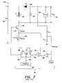
- FIG. 7is a circuit diagram illustrating an example of a current-mode regulator 58 based on the buck-boost converter configuration shown in FIG. 5 .
- additional details of the voltage regulation feedback control loop 46are shown to facilitate the discussion of input current limiting. It should be appreciated that the concepts discussed below in connection with the input current sensing and limiting features of the circuit of FIG. 7 may be similarly applied to the other types of conventional DC-DC converters discussed herein.
- the feedback control loop 46which controls the operation of the transistor switch 20 in the current-mode circuit of FIG. 7 differs from that shown in FIG. 1 in that the circuit of FIG. 7 additionally includes an input current sensing device 60 (i.e., the resistor R sense ) and a comparator 62 . Also, the pulse width modulator 36 used in the feedback control loop in the example of FIG. 7 is a D-type flip-flop with set and reset control. As shown in FIG.
- the flip-flop pulse width modulatoris arranged such that its “D” and “Clk” inputs are tied to ground, the oscillator 26 provides the pulse stream 42 to the “Set” input of the flip-flop (low activated, S ), the comparator 62 provides a signal 64 to the “Reset” input of the flip-flop (low activated, R ), and the flip-flop's “Q” output provides the pulse width modulated control signal 44 .
- the transistor switch 20when the transistor switch 20 is off or open, there is no current through the resistor R sense ; hence, the voltage at the inverting input of the comparator 62 is zero.
- the error signal 38 in this exampleis a positive voltage over some predetermined range that indicates the difference between the sampled output voltage V sample and V ref .
- the signal 64 output by the comparatoris a logic high signal (i.e., the reset input R of the flip-flop is not activated).
- the next low-going pulse of the pulse stream 42activates the flip-flop's set input S , thereby driving the flip-flop's Q output to a logic high state and turning the transistor switch 20 on.
- thiscauses the inductor current I L to increase, and with the switch closed this inductor current (I L(on) ) also passes through the resistor R sense , thereby developing a voltage V sense across this resistor.
- the signal 64 output by the comparator 62switches to a logic low state, thereby activating the flip-flop's reset input R and causing the Q output to go low (and the transistor switch 20 to turn off).
- the relationship between V sense and the error signal 38determines the duty cycle D of the transistor switch 20 ; specifically, if the voltage V sense exceeds the error signal 38 , the switch opens.
- the peak current I P through the inductormay be predetermined by selecting an appropriate value for the resistor R sense , given the expected range of the error signal 38 .
- the action of the comparator 62ensures that even in situations where changes in load requirements cause V sample to be substantially below V ref (resulting in a relatively higher magnitude error signal and a potentially greater duty cycle), the current I L(on) through the inductor ultimately may limit the duty cycle so that the inductor current does not exceed a predetermined peak current.
- this type of “current-mode” operationgenerally enhances the stability of the feedback control loop and reduces potentially damaging conditions in the DC-DC converter circuitry.
- power suppliesmay be configured to provide a regulated DC output voltage from an input AC line voltage (e.g., 120 V rms , 60 Hz).
- an input AC line voltagee.g. 120 V rms , 60 Hz.
- conventional “linear” power suppliestypically employ a substantial (relatively large and heavy) 60 Hz power transformer to reduce the input AC line voltage at approximately 120 V rms to some lower (and less dangerous) secondary AC voltage. This lower secondary AC voltage then is rectified (e.g., by a diode bridge rectifier) and filtered to provide an unregulated DC voltage.
- a linear regulatoris then employed to provide a predetermined regulated DC voltage output based on the unregulated DC voltage.
- an unregulated DC voltagemay be provided as an input to a DC-DC converter directly from a rectified and filtered AC line voltage.
- a DC-DC converterdirectly from a rectified and filtered AC line voltage.
- the unregulated DC input voltage to the convertermay be approximately 160 Volts DC (based on a rectified 120 V rms line voltage) or higher (up to approximately 400 Volts if power factor correction is employed, as discussed below in connection with FIGS. 9A and 9B ), which is potentially quite dangerous.
- DC-DC converters for such power supply arrangementstypically are configured with isolation features to address these issues so as to generally comport with appropriate safety standards.
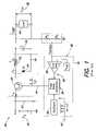
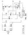
- FIG. 8is a circuit diagram illustrating an example of such a power supply 66 incorporating a DC-DC converter or switching regulator.
- the power supply 66receives as an input an AC line voltage 67 which is rectified by a bridge rectifier 68 and filtered by a capacitor 35 (C filter ) to provide an unregulated DC voltage as an input V in to the DC-DC converter portion 69 .
- the DC-DC converter portion 69is based on the inverting regulator (buck-boost) arrangement shown in FIG. 5 ; however, in FIG. 8 , the energy-storage inductor has been replaced with a high frequency transformer 72 to provide isolation between the unregulated high DC input voltage V in and the DC output voltage V out .
- Such a DC-DC converter arrangement incorporating a transformer rather than an inductorcommonly is referred to as a “flyback” converter.
- the “secondary side” of the converter portion 69i.e., the diode D 1 and the capacitor C
- the converterprovides a DC output voltage having the same polarity as the DC input voltage (note the opposing “dot” convention for the windings of the transformer 72 , indicating that the primary transformer winding is wound in the opposite direction of the secondary transformer winding).
- the DC-DC converter portion 69also includes an isolation element 70 (e.g., a second high-frequency transformer or optoisolator) in the voltage regulation feedback control loop to link the error signal from the error amplifier 28 to the modulator 36 (the error signal input to and output from the isolation element 70 is indicated by the reference numerals 38 A and 38 B).
- power for the oscillator/modulation circuitrygenerally may be derived from the primary side unregulated higher DC input voltage V in
- power for other elements of the feedback control loope.g., the reference voltage V ref , the error amplifier 28
- V refthe reference voltage
- V outthe secondary side regulated DC output voltage
- power for the components of the feedback loopmay in some cases be provided by an independent power source.
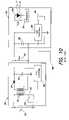
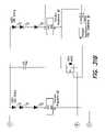
- FIG. 9is a circuit diagram illustrating yet another example of a power supply 74 incorporating a different type of DC-DC converter that provides input-output isolation.
- the DC-DC converter portion 75 of the power supply 74 shown in FIG. 9commonly is referred to as a “forward” converter, and is based on the step-down or “buck” converter discussed above in connection with FIG. 1 .
- the converter portion 75again includes a transformer 72 like the circuit of FIG. 8 , but also includes a secondary side inductor 76 and additional diode 77 (D 2 ) not present in the flyback converter shown in FIG. 8 (note that the diode D 2 , the inductor 76 and the capacitor 34 resemble the buck converter configuration illustrated in FIG. 1 ).
- the diode D 1ensures that only positive transformer secondary voltages are applied to the output circuit while diode D 2 provides a circulating path for current in the inductor 76 when the transformer voltage is zero or negative.
- both of the exemplary power supplies shown in FIGS. 8 and 9may be modified to incorporate current-mode features as discussed above in connection with FIG. 7 (i.e., to limit the current in the primary winding of the transformer 72 ).
- FIGS. 8 and 9include two isolation elements (e.g., the transformer 72 and the isolation element 70 ) as opposed to a single 60 Hz power transformer as in a linear power supply, the difference in size and weight between a switching power supply and a linear power supply is significant; the size of a transformer generally is determined by the core size, which decreases dramatically at the higher switching frequencies of the switching supply (on the order of 50 kHz to 100 kHz) as opposed to the line frequency (60 Hz). Also, switching supplies operate at significantly cooler temperatures as a result of their increased efficiency and lower heat dissipation as compared to linear supplies. As a result, switching power supplies are commonly utilized for many consumer electronics applications (e.g., computers and other electronic instruments and devices).
- Examples of commercial switching power supply packagesinclude small modular units, wall plug-ins, open-framed units, or enclosed units. Small modular units generally are used in moderately low-power applications from approximately 10 to 25 Watts. Wall plug-in supplies typically provide even less power, while open-framed or enclosed units may be configured to supply substantially more power (e.g., 500 to 1000 Watts or more). Examples of common regulated DC output voltages from commercially available switching power supplies include ⁇ 5V, ⁇ 12V, ⁇ 15V, and 24V.
- DC-DC convertersBecause of the switching nature of DC-DC converters, these apparatus generally draw current from a power source in short pulses (e.g., see I in FIG. 2 ). This condition may have some generally undesirable effects when DC-DC converters draw power from an AC power source (e.g., as in the arrangements of FIGS. 8 and 9 ).
- the input current ultimately drawn from the AC line voltageideally should have a sinusoidal wave shape and be in phase with the AC line voltage. This situation commonly is referred to as “unity power factor,” and generally results with purely resistive loads.
- the switching nature of the DC-DC converter and resulting pulsed current drawi.e., significantly non-sinusoidal current draw, however, causes these apparatus to have less than unity power factor, and thus less than optimum power efficiency (notwithstanding their improved efficiency over conventional linear supplies).
- the “apparent power” drawn from an AC power source by a load that is not a purely resistive loadis given by multiplying the RMS voltage applied to the load and the RMS current drawn by the load.
- This apparent powerreflects how much power the device appears to be drawings from the source.
- the actual power drawn by the loadmay be less than the apparent power, and the ratio of actual to apparent power is referred to as the load's “power factor” (the power factor traditionally is given by the cosine of the phase angle between applied voltage and current drawn).
- a device that draws an apparent power of 100 Volt-amps and has a 0.5 power factoractually consumes 50 Watts of power, not 100 Watts; stated differently, in this example, a device with a 0.5 power factor appears to require twice as much power from the source than it actually consumes.
- DC-DC converterscharacteristically have significantly less than unity power factor due to their switching nature and pulsed current draw. Additionally, if the DC-DC converter were to draw current from the AC line voltage with only intervening rectification and filtering, the pulsed non-sinusoidal current drawn by the DC-DC converter would place unusual stresses and introduce generally undesirable noise and harmonics on the AC line voltage (which may adversely affect the operation of other devices drawing power from the AC line voltage).
- some conventional switching power suppliesare equipped with, or used in conjunction with, power factor correction apparatus that are configured to address the issues noted above and provide for a more efficient provision of power from an AC power source.
- power factor correction apparatusgenerally operate to “smooth out” the pulsed current drawn by a DC-DC converter, thereby lowering its RMS value, reducing undesirable harmonics, improving the power factor, and reducing the chances of an AC mains circuit breaker tripping due to peak currents.
- a power factor correction apparatusis itself a type of switched power converter device, similar in construction to the various DC-DC converters discussed above, and disposed for example between an AC bridge rectifier and a DC-DC converter that ultimately provides power to a load.
- This type of power factor correction apparatusacts to precisely control its input current on an instantaneous basis so as to substantially match the waveform and phase of its input voltage (i.e., a rectified AC line voltage).
- the power factor correction apparatusmay be configured to monitor a rectified AC line voltage and utilize switching cycles to vary the amplitude of the input current waveform to bring it closer into phase with the rectified line voltage.
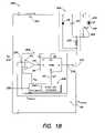
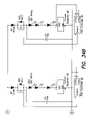
- FIG. 9Ais a circuit diagram generally illustrating such a conventional power factor correction apparatus 520 .
- the power factor correction apparatusis configured so as to receive as an input 65 the rectified AC line voltage V AC from the bridge rectifier 68 , and provide as an output the voltage V in that is then applied to a DC-DC converter portion of a power supply (e.g., with reference to FIGS. 8 and 9 , the power factor correction apparatus 520 would be disposed between the bridge rectifier 68 and the DC-DC converter portions 69 and 75 , respectively).
- a common example of a power factor correction apparatus 520is based on a boost converter topology (see FIG. 4 for an example of a DC-DC converter boost configuration) that includes an inductor L PFC , a switch SW PFC , a diode D PFC , and the filter capacitor 35 across which the voltage V in is generated.
- the power factor correction apparatus 520 of FIG. 9Aalso includes a power factor correction (PFC) controller 522 that monitors the rectified voltage V AC , the generated voltage V in provided as an output to the DC-DC converter portion, and a signal 71 (I sump ) representing the current I AC drawn by the apparatus 520 .
- the signal I sampmay be derived from a current sensing element 526 (e.g., a voltage across a resistor) in the path of the current I AC drawn by the apparatus.
- the PFC controller 522is configured to output a control signal 73 to control the switch 75 (SW PFC ) such that the current I AC has a waveform that substantially matches, and is in phase with, the rectified voltage V AC .
- the PFC controller 522 shown in FIG. 9Bimplements a control strategy based on two feedback loops, namely a voltage feedback loop and a current feedback loop. These feedback loops work together to manipulate the instantaneous current I AC drawn by the power factor correction apparatus based on a derived effective conductance G PFC for the power factor correction apparatus.
- a voltage feedback loop 524is implemented by comparing the voltage V in (provided as an output across the filter capacitor 35 ) to a reference voltage V refPFC representing a desired regulated value for the voltage V in . The comparison of these values generates an error voltage signal V e which is applied to an integrator/low pass filter having a cutoff frequency of approximately 10-20 Hz.
- This integrator/low pass filterimposes a relatively slow response time for the overall power factor control loop, which facilitates a higher power factor; namely, because the error voltage signal V e changes slowly compared to the line frequency (which is 50 or 60 Hz), adjustments to I AC due to changes in the voltage V in (e.g., caused by sudden and/or significant load demands) occur over multiple cycles of the line voltage rather than abruptly during any given cycle.
- the signal I* ACis compared to the signal I samp which represents the actual current I AC being drawn by the apparatus 520 .
- the comparison of these valuesgenerates a current error signal I e that serves as a control signal for a pulse width modulated (PWM) switch controller (e.g., similar to that discussed above in connection with FIG. 7 ).
- PWMpulse width modulated
- the PWM switch controllerin turn outputs a signal 73 to control the switch SW PFC so as to manipulate the actual current I AC being drawn (refer again to FIG. 9A ).
- Exemplary frequencies commonly used for the control signal 73 output by the PWM switch controller (and hence for the switch SW PFC )are on the order of approximately 100 kHz.
- the power factor correction apparatus 520provides as an output the regulated voltage V in across the capacitor 35 , from which current may be drawn as needed by a load coupled to V in (e.g., by a subsequent DC-DC converter portion of a power supply).
- a load coupled to V ine.g., by a subsequent DC-DC converter portion of a power supply.
- the instantaneous value of the voltage V inmay change dramatically; for example, in instances of sudden high load power requirements, energy reserves in the capacitor are drawn upon and V in may suddenly fall below the reference V refPFC .
- the voltage feedback loop 524attempts to adjust V in by causing the power factor correction apparatus to draw more current from the line voltage.
- a power factor correction apparatusmay not be required or even significantly effective.
- the power factor of the switching power supplyconventionally is considered to be not as important as in higher power applications; presumably, the power drawn by a small load comprises a relatively insignificant portion of the overall power available on a particular AC power circuit.
- power factor correctionmay be important for larger loads consuming relatively higher power, in which the input current to the switching power supply may approach the maximum available from the AC power source.
- a controlled predetermined poweris provided to a load without requiring any feedback information from the load (i.e., without monitoring load voltage and/or current). Furthermore, in one aspect of these embodiments, no regulation of load voltage and/or load current is required. In another aspect of such embodiments in which feedback is not required, isolation components typically employed between a DC output voltage of a DC-DC converter (e.g., the load supply voltage) and a source of power derived from an AC line voltage (e.g., a high DC voltage input to the DC-DC converter) in some cases may be eliminated, thereby reducing the number of required circuit components. In yet another aspect, eliminating the need for a feedback loop generally increases circuit speed and avoids potentially challenging issues relating to feedback circuit stability.
- This type of switching operationfacilitates the transfer of a predictable quantum of energy per switching cycle, and hence a predictable controlled power delivery to the light source.
- the discontinuous mode switching operation employed in this embodimentmay be similarly used in various feed-forward implementations for providing power to loads other than LED-based light sources (e.g., motors, actuators, relays, heating elements, etc.)
- a modified power factor correction apparatusis based on a DC-DC converter switching architecture (e.g., a boost converter), wherein control of the apparatus' switching operation is based on a predetermined desired load power and, more particularly, a total anticipated power draw from an AC power source.
- a DC-DC converter switching architecturee.g., a boost converter
- control of the apparatus' switching operationis based on a predetermined desired load power and, more particularly, a total anticipated power draw from an AC power source.
- the overall control loop response of the power factor correction apparatusmay be significantly improved, particularly in situations in which the load power traverses a wide range in a short time period (e.g., load full off to load full on, or vice versa).
- a more stable power factor correctionmay be realized, in which smaller circuit components may be employed based on more predictable expectations for signal values, thereby reducing the cost and/or size of the implemented circuits.
- a power factor correction apparatusas described immediately above may be used in combination with one or more feed-forward drivers to efficiently provide power from an AC power source to one or more of a variety of loads, including LED-based light sources.
- multiple apparatuseach including one or more loads, one or more power control apparatus (i.e., feed-forward drivers), and an optional conventional or modified power factor control apparatus, may be coupled to a distributed source of power (e.g., a distributed DC voltage or AC line voltage) in a network configuration.
- a distributed source of powere.g., a distributed DC voltage or AC line voltage
- the multiple apparatus coupled to the distributed voltagemay be configured as addressable devices so as to facilitate appropriate communication of load control information throughout the network.
- the load control informationmay be formatted for communication throughout the network in any of a variety of conventional communication protocols including, but not limited to, a DMX protocol.
- One embodimentis directed to an apparatus, comprising at least one first LED, and at least one first power controller to provide a first controllably variable predetermined power to the at least one first LED without requiring any feedback information associated with the at least one first LED.
- Another embodimentis directed to a method, comprising an act of providing a first controllably variable predetermined power to at least one first LED without requiring any feedback information associated with the at least one first LED.
- Another embodimentis directed to an apparatus, comprising at least one first LED, and at least one first power controller configured to provide a first controllably variable predetermined power to the at least one first LED.
- the at least one first power controllerincludes a first single switch, a DC supply voltage provides a power source to the apparatus, the at least one first power controller is configured to apply a first converted DC voltage across the at least one first LED, and the at least one first power controller is further configured to control the first single switch to facilitate a first conversion of the DC supply voltage to the first converted DC voltage and concurrently provide the first controllably variable predetermined power to the at least one first LED.
- Another embodimentis directed to a method, comprising an act of providing a first controllably variable predetermined power to at least one first LED, wherein a DC supply voltage provides a power source, wherein a first converted DC voltage is applied across the at least one first LED.
- the act of providing a first controllably variable predetermined powerfurther includes an act of controlling a first single switch to facilitate a first conversion of the DC supply voltage to the first converted DC voltage and concurrently provide the first controllably variable predetermined power to the at least one first LED.
- Another embodimentis directed to an apparatus, comprising at least one first LED configured to generate first radiation having a first spectrum, and a first feed-forward driver coupled to the at least one first LED and configured to controllably vary a first intensity of the first radiation without monitoring or regulating a first voltage or a first current provided to the at least one first LED.
- Another embodimentis directed to a method, comprising acts of generating first radiation having a first spectrum from at least one first LED, and controllably varying a first intensity of the first radiation without monitoring or regulating a first voltage or a first current provided to the at least one first LED.
- Another embodimentis directed to a network, comprising a distributed DC voltage to provide a power source to the network, and at least first and second apparatus coupled to the distributed DC voltage.
- Each of the first and second apparatusincludes at least one first LED configured to generate first radiation having a first spectrum, and a first feed-forward driver coupled to the at least one first LED and configured to control a first intensity of the first radiation without monitoring or regulating a first voltage or a first current provided to the at least one first LED.
- the networkfurther comprises at least one network controller, coupled to each of the first and second apparatus, to generate at least one radiation control signal that includes information representing the first intensity of the first radiation generated by each of the first and second apparatus.
- Another embodimentis directed to a method, comprising acts of: distributing a DC supply voltage to at least first and second apparatus to provide a power source; in each of the first and second apparatus, generating first radiation having a first spectrum from at least one first LED; transmitting to both the first and second apparatus at least one radiation control signal that includes information representing a first intensity of the first radiation generated by each of the first and second apparatus; and in each of the first and second apparatus, controlling the first intensity of the first radiation, in response to the at least one radiation control signal, without monitoring or regulating a first voltage or a first current provided to the at least one first LED.
- Another embodimentis directed to a network, comprising a distributed AC line voltage and at least first and second apparatus coupled to the distributed AC line voltage.
- Each of the first and second apparatusincludes at least one first LED configured to generate first radiation having a first spectrum, and a first feed-forward driver coupled to the at least one first LED and configured to control a first intensity of the first radiation without monitoring or regulating a first voltage or a first current provided to the at least one first LED.
- the networkfurther comprises at least one network controller, coupled to each of the first and second apparatus, to generate at least one radiation control signal that includes information representing the first intensity of the first radiation generated by each of the first and second apparatus.
- Another embodimentis directed to a method, comprising acts of: distributing an AC line voltage to at least first and second apparatus; in each of the first and second apparatus, generating first radiation having a first spectrum from at least one first LED; transmitting to both the first and second apparatus at least one radiation control signal that includes information representing a first intensity of the first radiation generated by each of the first and second apparatus; and in each of the first and second apparatus, controlling the first intensity of the first radiation, in response to the at least one radiation control signal, without monitoring or regulating a first voltage or a first current provided to the at least one first LED.
- Another embodimentis directed to an apparatus, comprising at least one energy transfer element to store input energy derived from a power source and to provide output energy to a load, at least one switch coupled to the at least one energy transfer element to control at least the input energy stored to the at least one energy transfer element, and at least one switch controller configured to receive at least one control signal representing a desired load power and control the at least one switch in response to the at least one control signal, wherein the at least one switch controller does not receive any feedback information relating to the load to control the at least one switch.
- Another embodimentis directed to a method, comprising acts of: storing input energy derived from a power source to at least one energy transfer element; providing output energy from the at least one energy transfer element to a load; controlling at least the input energy stored to the at least one energy transfer element via at least one switch coupled to the at least one energy transfer element; receiving at least one control signal representing a desired load power; and controlling the at least one switch in response to the at least one control signal without receiving any feedback information relating to the load.
- Another embodimentis directed to an apparatus, comprising at least one energy transfer element to store input energy derived from a power source and to provide output energy to a load, at least one switch coupled to the at least one energy transfer element to control at least the input energy stored to the at least one energy transfer element, and at least one switch controller configured to control the at least one switch, wherein the at least one switch controller is configured to control at least one of a frequency and a duty cycle of multiple switching operations of the at least one switch so as to provide a controllably variable predetermined power to the load.
- Another embodimentis directed to a method, comprising acts of: storing input energy derived from a power source to at least one energy transfer element; providing output energy from the at least one energy transfer element to a load; controlling at least the input energy stored to the at least one energy transfer element via at least one switch coupled to the at least one energy transfer element; and controlling at least one of a frequency and a duty cycle of multiple switching operations of the at least one switch so as to provide a controllably predetermined variable power to the load.
- Another embodimentis directed to an apparatus, comprising at least one energy transfer element to store input energy derived from a power source and to provide output energy to a load, at least one switch coupled to the at least one energy transfer element to control at least the input energy stored to the at least one energy transfer element, and at least one switch controller configured to control the at least one switch, wherein the at least one switch controller is configured to control the at least one switch based on at least one of a voltage output by the power source and a current drawn from the power source, and at least one control signal representing a desired load power, so as to provide a controllably variable predetermined power to the load.
- Another embodimentis directed to a method, comprising acts of: storing input energy derived from a power source to at least one energy transfer element; providing output energy from the at least one energy transfer element to a load; controlling at least the input energy stored to the at least one energy transfer element via at least one switch coupled to the at least one energy transfer element; and controlling the at least one switch based on at least one of a voltage output by the power source and a current drawn from the power source, and at least one control signal representing a desired load power, so as to provide a controllably predetermined variable power to the load.
- Another embodimentis directed to an apparatus, comprising at least one energy transfer element to store input energy derived from a power source and to provide output energy to a load, at least one switch coupled to the at least one energy transfer element to control at least the input energy stored to the at least one energy transfer element, and at least one switch controller configured to control the at least one switch to perform multiple switching operations in at least one time period, each switching operation transferring a predetermined quantum of the input energy to the at least one energy transfer element.
- the at least one switch controlleris configured to control the multiple switching operations so as to vary at least one of the predetermined quantum of the input energy for at least two switching operations in the at least one time period and a number of the multiple switching operations in the at least one time period, so as to provide a controllably variable power to the load.
- Another embodimentis directed to a method, comprising acts of: storing input energy derived from a power source to at least one energy transfer element; providing output energy from the at least one energy transfer element to a load; controlling at least the input energy stored to the at least one energy transfer element via at least one switch coupled to the at least one energy transfer element; and controlling the at least one switch to perform multiple switching operations in at least one time period, each switching operation transferring a controllably variable predetermined quantum of the input energy to the at least one energy transfer element.
- the act of controlling the at least one switchfurther comprises an act of controlling the multiple switching operations so as to vary at least one of the predetermined quantum of the input energy for at least two switching operations in the at least one time period and a number of the multiple switching operations in the at least one time period, so as to provide a controllably variable power to the load.
- Another embodimentis directed to a power factor correction apparatus, comprising at least one first switch, and at least one switch controller to control the at least one first switch based at least on a predetermined desired power to be provided to a load coupled to the power factor correction apparatus.
- Another embodimentis directed to a power factor correction method, comprising an act of controlling a current drawn from an AC power source based at least on a predetermined desired power to be provided to a load from the AC power source, so as to improve a power factor associated with the provision of actual power to the load.
- Another embodimentis directed to an apparatus, comprising at least one power factor correction switch, at least one power control switch, and at least one switch controller to control both the at least one power factor correction switch and the at least one power control switch based at least on a predetermined desired power to be provided to a load coupled to the apparatus.
- the term “LED”should be understood to include any electroluminescent diode or other type of carrier injection/junction-based system that is capable of generating radiation in response to an electric signal.
- the term LEDincludes, but is not limited to, various semiconductor-based structures that emit radiation in response to current, light emitting polymers, electroluminescent strips, and the like.
- LEDrefers to light emitting diodes of all types (including semi-conductor and organic light emitting diodes) that may be configured to generate radiation in one or more of the infrared spectrum, ultraviolet spectrum, and various portions of the visible spectrum (generally including radiation wavelengths from approximately 400 nanometers to approximately 700 nanometers).
- Some examples of LEDsinclude, but are not limited to, various types of infrared LEDs, ultraviolet LEDs, red LEDs, blue LEDs, green LEDs, yellow LEDs, amber LEDs, orange LEDs, and white LEDs (discussed further below). It also should be appreciated that LEDs may be configured to generate radiation having various bandwidths for a given spectrum (e.g., narrow bandwidth, broad bandwidth).
- an LED configured to generate essentially white lightmay include a number of dies which respectively emit different spectra of electroluminescence that, in combination, mix to form essentially white light.
- a white light LEDmay be associated with a phosphor material that converts electroluminescence having a first spectrum to a different second spectrum.
- electroluminescence having a relatively short wavelength and narrow bandwidth spectrum“pumps” the phosphor material, which in turn radiates longer wavelength radiation having a somewhat broader spectrum.
- an LEDdoes not limit the physical and/or electrical package type of an LED.
- an LEDmay refer to a single light emitting device having multiple dies that are configured to respectively emit different spectra of radiation (e.g., that may or may not be individually controllable).
- an LEDmay be associated with a phosphor that is considered as an integral part of the LED (e.g., some types of white LEDs).
- the term LEDmay refer to packaged LEDs, non-packaged LEDs, surface mount LEDs, chip-on-board LEDs, T-package mount LEDs, radial package LEDs, power package LEDs, LEDs including some type of encasement and/or optical element (e.g., a diffusing lens), etc.
- a given light sourceincluding an LED, may be configured to generate electromagnetic radiation within the visible spectrum, outside the visible spectrum, or a combination of both.
- the terms “light” and “radiation”are used interchangeably herein.
- the term “spectrum”should be understood to refer to any one or more frequencies (or wavelengths) of radiation produced by one or more light sources. Accordingly, the term “spectrum” refers to frequencies (or wavelengths) not only in the visible range, but also frequencies (or wavelengths) in the infrared, ultraviolet, and other areas of the overall electromagnetic spectrum.
- a given spectrummay have a relatively narrow bandwidth (essentially few frequency or wavelength components) or a relatively wide bandwidth (several frequency or wavelength components having various relative strengths). It should also be appreciated that a given spectrum may be the result of a mixing of two or more other spectra (e.g., mixing radiation respectively emitted from multiple light sources).
- coloris used interchangeably with the term “spectrum.”
- the term “color”generally is used to refer primarily to a property of radiation that is perceivable by an observer (although this usage is not intended to limit the scope of this term). Accordingly, the terms “different colors” implicitly refer to multiple spectra having different wavelength components and/or bandwidths. It also should be appreciated that the term “color” may be used in connection with both white and non-white light.
- one or more light sourcesmay be configured such that the radiation generated by the sources may be directly viewed by an observer (e.g., display), indirectly viewed (e.g., illumination), or used for other applications in which the radiation is not necessarily viewed by an observer (e.g., machine vision).
- an observere.g., display
- indirectly viewede.g., illumination
- other applicationse.g., machine vision
- controlleris used herein to describe various apparatus relating to the operation of one or more other devices.
- a controllercan be implemented in numerous ways, such as with dedicated hardware including various analog and/or digital circuitry, by employing one or more microprocessors or other programmable devices configured to execute predetermined algorithms (e.g., programmed using software or microcode) to perform the various functions discussed herein, or as a combination of dedicated hardware to perform some functions and programmed microprocessors and associated circuitry to perform other functions.
- processorgenerally refers to a controller that includes one or more microprocessors or other programmable devices.
- a controller or processormay be associated with one or more storage media (generically referred to herein as “memory,” e.g., volatile and non-volatile computer memory such as RAM, PROM, EPROM, and EEPROM, floppy disks, compact disks, optical disks, magnetic tape, etc.).
- the storage mediamay be encoded with one or more programs that, when executed on one or more processors/controllers, perform at least some of the functions discussed herein.
- Various storage mediamay be fixed within a processor/controller or may be transportable, such that the one or more programs stored thereon can be loaded into a processor/controller so as to implement various aspects of the present disclosure discussed herein.
- programor “computer program” are used herein in a generic sense to refer to any type of computer code (e.g., software or microcode) that can be employed to program one or more processors/controllers.
- addressableis used herein to refer to a device (e.g., a controller or processor that may be associated with one or more loads such as a lighting apparatus) that is configured to receive information (e.g., data) intended for multiple devices, including itself, and to selectively respond to particular information intended for it.
- informatione.g., data
- addressableoften is used in connection with a networked environment (or a “network,” discussed further below), in which multiple devices are coupled together via some communications medium or media.
- one or more devices coupled to a networkmay serve as a controller for one or more other devices coupled to the network (e.g., in a master/slave relationship).
- a networked environmentmay include one or more dedicated controllers that are configured to control one or more of the devices coupled to the network.
- multiple devices coupled to the networkeach may have access to data that is present on the communications medium or media; however, a given device may be “addressable” in that it is configured to selectively exchange data with (i.e., receive data from and/or transmit data to) the network, based, for example, on one or more particular identifiers (e.g., “addresses”) assigned to it.
- networkrefers to any interconnection of two or more devices (including controllers or processors) that facilitates the transport of information (e.g. for device control, data storage, data exchange, etc.) between any two or more devices and/or among multiple devices coupled to the network.
- networkssuitable for interconnecting multiple devices may include any of a variety of network topologies and employ any of a variety of communication protocols.
- any one connection between two devicesmay represent a dedicated connection between the two systems, or alternatively a non-dedicated connection.
- non-dedicated connectionmay carry information not necessarily intended for either of the two devices (e.g., an open network connection).
- various networks of devices as discussed hereinmay employ one or more wireless, wire/cable, and/or fiber optic links to facilitate information transport throughout the network.
- FIG. 1is a circuit diagram of a conventional step-down or “buck” type DC-DC converter
- FIG. 2is a diagram illustrating various operating signals associated with the DC-DC converter of FIG. 1 ;
- FIG. 3is a diagram particularly illustrating inductor current vs. applied voltage during two consecutive switching operations in the converter of FIG. 1 ;
- FIG. 4is a circuit diagram of a conventional step-up or “boost” type DC-DC converter
- FIG. 5is a circuit diagram of a conventional inverting or “buck-boost” type DC-DC converter
- FIG. 6is a circuit diagram of a conventional “CUK” type DC-DC converter
- FIG. 7is a circuit diagram of a buck-boost converter similar to that shown in FIG. 5 , configured for current-mode operation;
- FIG. 8is a circuit diagram of a conventional “flyback” type DC-DC converter
- FIG. 9is a circuit diagram of a conventional “forward” type DC-DC converter
- FIG. 9Ais a circuit diagram of a conventional power factor correction apparatus based on a boost converter topology
- FIG. 9Bis a diagram that conceptually illustrates the functionality of a power factor correction controller of the power factor correction apparatus shown in FIG. 9A ;
- FIG. 10is a diagram schematically showing an exemplary conventional arrangement of a DC-DC converter coupled to a load that is configured to modulate power delivered to one or more functional components of the load;
- FIG. 11is a diagram schematically showing another exemplary conventional arrangement of a DC-DC converter coupled to a load that is configured to modulate power delivered to one or more functional components of the load;
- FIG. 12is a block diagram illustrating a “feed-forward” power control apparatus based at least in part on a switching power supply configuration, according to one embodiment of the disclosure
- FIG. 13is a diagram showing some additional details of the power control apparatus of FIG. 12 , according to one embodiment of the disclosure.
- FIG. 14is an exemplary timing diagram for the apparatus of FIGS. 12 and 13 , according to one embodiment of the disclosure.
- FIG. 15is a circuit diagram illustrating a portion of the power control apparatus of FIGS. 12 and 13 according to one embodiment of the disclosure, in which the apparatus is controlled based in part on monitoring an inductor current drawn from a source of power and adjusting a duty cycle of a switching operation;
- FIG. 16is a circuit diagram illustrating a portion of the power control apparatus of FIGS. 12 and 13 according to another embodiment of the disclosure, in which the apparatus is controlled based in part on monitoring an input voltage to the apparatus and adjusting a duty cycle of a switching operation;
- FIG. 17is a circuit diagram illustrating a portion of a switch controller of the power control apparatus of FIGS. 12 and 13 according to another embodiment of the disclosure, in which the apparatus is controlled based on adjusting an effective frequency of a switching operation;
- FIG. 18is a diagram illustrating a power control apparatus according to another embodiment of the disclosure, in which both the duty cycle and effective switching frequency of a switching operation may be controlled to control power to a load;
- FIG. 19is a diagram illustrating a power control apparatus according to yet another embodiment of the disclosure, in which both the duty cycle and effective switching frequency of a switching operation may be controlled to control power to a load;
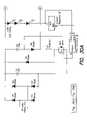
- FIG. 20is a circuit diagram illustrating a portion of a power control apparatus incorporating a tapped inductor, according to one embodiment of the disclosure
- FIG. 20Ais a circuit diagram illustrating the portion of the power control apparatus shown in FIG. 20 , with additional components to reduce residual stored energy, according to one embodiment of the disclosure;
- FIG. 21is a block diagram illustrating a lighting network based on multiple power control apparatus, according to one embodiment of the disclosure.
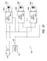
- FIG. 22is a diagram of a lighting apparatus incorporating multiple power control apparatus according to one embodiment of the disclosure.
- FIG. 22Ais a diagram of a lighting apparatus similar to that shown in FIG. 22 , with modified power factor correction control, according to one embodiment of the disclosure;
- FIG. 22Bis a diagram illustrating circuit generalities of a power factor correction apparatus of FIG. 22A and a conceptual functional block diagram of a portion of a processor dedicated to control of the power factor correction apparatus, according to one embodiment of the disclosure;
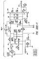
- FIG. 22Cis a diagram illustrating further circuit details of the power factor correction apparatus shown in FIGS. 22A and 22B , according to one embodiment of the present disclosure
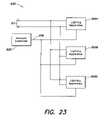
- FIG. 23is a block diagram illustrating a lighting network based on multiple lighting apparatus similar to that shown in FIG. 22 , according to one embodiment of the disclosure;
- FIG. 23Ais a block diagram illustrating an alternative lighting network based on multiple lighting apparatus similar to that shown in FIG. 22 , according to one embodiment of the disclosure;
- FIGS. 24A , 24 B, 24 C, 24 D and 24 Eare diagrams illustrating various views of housing configurations for the lighting apparatus of FIG. 22 , according to one embodiment of the disclosure;
- FIGS. 25-34are circuit diagrams illustrating a variety of power control apparatus configurations according to other embodiments of the disclosure.
- Applicantshave recognized and appreciated that for some applications and for some types of loads, the functions of providing appropriate power to the load and controlling some functionality associated with the load may be significantly streamlined, resulting in circuit implementations that have fewer components, higher overall power efficiencies, and smaller space requirements.
- a controlled predetermined poweris provided to a load without requiring any feedback information from the load (e.g., without monitoring and/or regulation of load voltage and current), thereby significantly reducing circuit complexity, number of components, size and efficiency.
- loadsin which one or more functional components of the load are controlled by modulating power to the functional components.
- functional componentsmay include, but are not limited to, motors or other actuators and motorized/movable components (e.g., relays, solenoids), temperature control components (e.g. heating/cooling elements) and at least some types of light sources.
- power modulation control techniquesthat may be employed in the load to control the functional components include, but are not limited to, pulse frequency modulation, pulse width modulation, and pulse number modulation (e.g., one-bit D/A conversion).
- one type of load of interest for a streamlined power supply/control configurationis a lighting apparatus including one or more light-emitting diode (LED) light sources whose perceived brightness may be varied based on modulated pulsed power delivery.
- LEDlight-emitting diode
- a switching power supply including a DC-DC converterprovides power via a regulated DC output voltage to an LED-based lighting apparatus.
- FIG. 10is a diagram illustrating such an exemplary conventional arrangement of a DC-DC converter 69 and an LED-based lighting apparatus serving as a load 40 .
- the lighting apparatusincludes one or more LEDs 100 and various other components configured to control the intensity of radiation generated by the LED(s).
- LEDs 100include one or more LEDs 100 and various other components configured to control the intensity of radiation generated by the LED(s).
- One example of such an apparatusis described in U.S. Pat. No. 6,016,038, issued Jan. 18, 2000, entitled “Multicolored LED Lighting Method and Apparatus,” which patent hereby is incorporated herein by reference.
- the DC-DC converter 69 of FIG. 10is shown as a flyback regulator (first discussed above in connection with FIG. 8 ), and serves as a portion of a power supply which draws power from an A.C. power source (i.e., an A.C. line voltage such as 120 Vrms/60 Hz). Accordingly, the DC-DC converter 69 includes a transformer 72 and other components to provide appropriate isolation between the unregulated DC input voltage 30 (V in ) which is derived from the A.C. line voltage, and the regulated DC output voltage 32 (V out ). It should be appreciated that the forward converter of FIG. 9 , as well as other DC-DC converter configurations including input-output isolation features, and/or power factor correction components, likewise could be employed in conventional arrangements similar to that illustrated in FIG. 10 .
- the switch 20 of the DC-DC converter 69is shown generically as a controllable “make-brake” circuit connection to indicate that various components may be utilized to implement the function of the switch 20 (e.g., BJTs, FETs, as well as other signal amplifier/switch driver circuitry that may be required). Additionally, the components of the converter's voltage regulation feedback loop (refer to FIGS. 1 and 7 ) are indicated collectively in FIG. 10 as a power supply controller 80 , which receives as an input a sample of the DC output voltage V out and provides as an output the control signal 44 that operates the switch 20 . As discussed above in connection with FIGS.
- the components of the power supply controller 80are configured to vary the duty cycle of the control signal 44 (and hence the on-off operation of the switch 20 ) so as to adjust the amount of energy transferred across the transformer in a given time period, thereby making adjustments to V out so that it is regulated at an essentially constant predetermined output voltage level.
- the lighting apparatus serving as the load 40 in the exemplary arrangement of FIG. 10includes one or more LEDs 100 controlled by an LED controller 82 .
- the apparatusmay include multiple LEDs which may be interconnected in any of a variety of serial, parallel, or serial-parallel arrangements such that the converter's regulated supply voltage V out provides an appropriate voltage to drive the LEDs (an LED typically has a low forward voltage on the order of 2 to 4 Volts, and multiple LEDs may be connected in serial/parallel arrangements such that a more commonly available supply output voltage V out , such as 12 Volts or 24 Volts, may be applied to the LED arrangement without damaging the LEDs).
- V outa more commonly available supply output voltage
- the unregulated DC input voltage V in provided to the DC-DC converter 69may be on the order of approximately 160 Volts or even significantly higher, and the converter may be configured to provide a regulated DC output or supply voltage V out of 12 Volts or 24 Volts, for example.
- a common anode of the one or more LEDs 100may be connected to the positive terminal of the regulated supply voltage V out .
- the load 40also may include one or more filter capacitors 88 to filter any residual ripple on the supply voltage V out .
- the intensity of radiation generated by the one or more LEDs 100is proportional to the average power delivered to the LED(s) over a given time period. Accordingly, one technique for varying the intensity of radiation generated by the one or more LEDs involves modulating the power delivered to the LED(s). To this end, the lighting apparatus also includes a current regulator 84 and a switch 90 in the current path of the LEDs between +V out and ground, as well as an LED controller 82 (which also may be powered via the regulated supply voltage V out ).
- the regulator 84 of the lighting apparatus/load 40 shown in FIG. 10generally is configured to define the maximum current I LED through the one or more LEDs 100 when the switch 90 is closed so as to complete the current path.
- the LED controller 82may be configured to control the switch 90 using a pulse width modulation technique so as to modulate the average power delivered to the LED(s) over time.
- the LED controlleris configured to repeatedly open and close the switch 90 , thereby energizing the one or more LEDs in a pulsed fashion, preferably at a frequency that is greater than that capable of being detected by the human eye (e.g., greater than approximately 100 Hz). In this manner, an observer of the light generated by the LED(s) does not perceive discrete on and off cycles (commonly referred to as a “flicker effect”), but instead the integrating function of the eye perceives essentially continuous illumination.
- the perceived brightness of the generated lightmay be varied.
- the LED controller 82may accomplish this by adjusting the duty cycle of the switch 90 (i.e., by increasing or decreasing the time the switch is on or closed during successive switching cycles).
- the LED controller 82may receive a control signal or control data 86 which specifies the switch's duty cycle at any given time, and hence the perceived brightness of observed light.
- the lighting apparatus/load 40may include one or more additional LEDs 100 A having a color different than that of the LED(s) 100 .
- the circuit arrangement of the LED(s) 100 Ais similar to that of the LED(s) 100 ; namely, a common anode of the LED(s) 100 A is connected to the positive terminal of V out , and a regulator 84 A is configured to define the maximum current I LED(A) through the LED(s) 100 A when a switch 90 A is closed so as to complete the current path.
- a regulator 84 Ais configured to define the maximum current I LED(A) through the LED(s) 100 A when a switch 90 A is closed so as to complete the current path.
- the LED controller 82is configured to also control the switch 90 A using a pulse width modulation technique so as to control the average power delivered to the LED(s) 100 A over time (and hence the perceived brightness of light generated by the LEDs 100 A), as discussed above in connection with FIG. 10 .
- the LED controller 82 shown in FIG. 11further may be configured to control the switches 90 and 90 A independently (e.g., based on one or more control signals or control data 86 ) so as to independently adjust the perceived brightness of the differently colored light respectively generated by the LED(s) 100 and the LED(s) 100 A.
- a variety of different perceivable colorsmay be generated by the lighting apparatus based on well-established color mixing principles.
- lighting apparatus similar to those shown in FIGS. 10 and 11may include LEDs having three or more different colors, wherein the respective intensities of radiation generated by differently-colored LEDs are controlled independently in a manner similar to that discussed above, so as to generate a wide variety of variable-color light.
- switching power suppliesgenerally are commercially available with only a few predetermined voltage output levels (e.g., typically 5V, ⁇ 12V, ⁇ 15V, 24V, etc.) and selected ranges of power output capabilities (in large part determined by various industry conventions).
- the limited choices of output voltage and output power rating of commercially available switching power suppliesmay result in a less than optimum matching between supply voltage/power rating, and particular voltage/power requirements of a given load.
- the regulated DC output voltages typically available in commercial power suppliesmay not be ideally suited for the particular load in question, thereby requiring some voltage or current adjustment/regulation circuitry to appropriately drive one or more functional components of the load.
- V outcommonly available regulated DC supply voltages V out of 12 Volts or 24 Volts driving an LED-based lighting apparatus
- significantly lower voltage LEDsneed to be particularly interconnected and arranged in the lighting apparatus, together with a current regulator, to ensure proper operation of the LED(s) without damage.
- the requirement of a regulator or similar adjustment circuitry based on a less than optimum supply voltage V outinevitably wastes power and space.
- a power supply that is significantly over-specifiedi.e., capable of providing power outputs significantly greater than P LOAD
- P LOADpower outputs significantly greater than P LOAD
- the aforementioned inefficiency issuesrelate at least in part to some degree of inflexibility of the DC-DC converter, with respect to potential voltage and/or power mismatches between the converter and the load, as well as potential power transmission losses between the converter and the load.
- various embodiments of the present disclosureare directed generally to methods and apparatus for providing and controlling power to at least some types of loads, wherein overall power efficiency typically is improved and functional redundancy of components is significantly reduced as compared to conventional arrangements.
- implementations of methods and apparatus according to various embodiments disclosed hereingenerally involve significantly streamlined circuits having fewer components, higher overall power efficiencies, and smaller space requirements.
- a controlled predetermined poweris provided to a load without requiring any monitoring of load voltage and/or load current (i.e., without any feedback from the load).
- isolation components typically employed between a lower DC load supply voltage and a source of power derived from an AC line voltagee.g., a high DC voltage input to a DC-DC converter
- eliminating the need for a feedback loopgenerally increases circuit speed and avoids potentially challenging issues relating to feedback circuit stability.
- One embodiment disclosed hereinis particularly directed to a “feed-forward” driver for an LED-based light source.
- the feed-forward driveraccording to this embodiment combines the functionality of a DC-DC converter and a light source controller, and is configured to control the intensity of light generated by the light source based on modulating the average power delivered to the light source in a given time period, without monitoring or regulating the voltage or current provided to the light source.
- the feed-forward driveris configured to store energy to and release energy from one or more energy transfer elements using a “discontinuous mode” switching operation. This type of switching operation, as discussed further below, facilitates the transfer of a predictable quantum of energy per switching cycle, and hence a predictable controlled power delivery to the light source.
- FIG. 12is a block diagram illustrating a “feed-forward” power control apparatus 200 based at least in part on a switching power supply configuration, according to one embodiment of the present disclosure.
- the terms “feed-forward” used in connection with the embodiment of FIG. 12refer to circuit configurations in which information associated with a load (e.g., a desired power to be drawn by the load, a desired voltage to be applied across the load, etc.) is known in advance and used to facilitate circuit operation.
- a controlled predetermined poweris provided to a load via a switched energy transfer method without requiring any feedback information from the load; i.e., there is no requirement to monitor load voltage and/or load current. Rather, a controlled predetermined power is provided to the load based on monitoring one or more parameters relating to the source of power provided to the power control apparatus (e.g., a voltage input or current drawn from a power source), as well as other control information or data known in advance relating to desired load parameters.
- the source of power provided to the power control apparatuse.g., a voltage input or current drawn from a power source
- the power control apparatus 200receives a DC input voltage 212 (V in ) and draws an input current 210 (I in ) from a source of power.
- the DC input voltage 212may be a regulated or unregulated DC voltage and may be derived, for example, from a rectified and filtered AC line voltage or another DC source of power, as discussed above in connection with the DC input voltage 30 shown in earlier figures.
- FIG. 12also shows that the power control apparatus 200 is configured such that the input current I in passes through an energy transfer arrangement 202 via the operation of a switch 214 .
- the switch 214in turn is controlled by a switch controller 204 , which is configured to control the switch 214 via a control signal 216 that is generated in response to one or more monitored power source parameters 206 (e.g., V in and/or I in ) as well as other control information or data 208 provided to the apparatus 200 .
- monitored power source parameters 206e.g., V in and/or I in
- operating power for the switch controller 204may be derived from the DC input voltage V in or another source of power.
- the switch 214performs a role substantially similar to that of the transistor switches 20 shown in earlier figures. Accordingly, one exemplary implementation of the switch 214 includes, but is not limited to, one or more transistors (e.g., BJTs, FETs) configured to operate as a saturated switch, together with other signal amplifier/switch driver circuitry that may be required to properly operate the transistors.
- the energy transfer arrangement 202 illustrated in FIG. 12generally represents one of several possible circuit arrangements configured to implement the general functionality of a DC-DC converter providing power to a load.
- the energy transfer arrangement 202may include various components configured to implement the general functionality of one of a buck converter, a boost converter, a buck-boost converter, a CUK converter, a flyback converter, and a forward converter (all of which were discussed above in connection with FIGS. 1 and 4 - 9 ), as well as other DC-DC converter arrangements not specifically discussed herein.
- the energy transfer arrangement 202is configured to provide a DC output voltage 222 (V out ) to a load 218 .
- V outDC output voltage
- the energy transfer arrangement 202 in the embodiment of FIG. 12is not configured to provide any information pertaining to the load (e.g., load voltage and/or load current) as feedback to affect the control of the switch 214 .
- FIG. 12The interconnection of the energy transfer arrangement 202 to other components of the power control apparatus 200 is shown generally in FIG. 12 to facilitate an introductory discussion of the operation of the power control apparatus. It should be appreciated, however, that a particular interconnection of components in a given implementation of the power control apparatus 200 may be dictated by the type of DC-DC converter employed in the energy transfer arrangement 202 . Some examples of particular arrangements are discussed in greater detail below, in connection with FIGS. 13 and 15 - 19 .
- the feed-forward power control apparatus 200may be configured to store energy to, and release energy from, one or more energy transfer elements of the energy transfer arrangement 202 using a “discontinuous mode” switching operation implemented by the switch controller 204 and the switch 214 .
- This type of switching operationfacilitates the transfer of a predictable quantum of energy per switching cycle, and hence a predictable controlled power delivery to the load 218 .
- the discontinuous mode switching operationis now discussed in greater detail, with reference initially to FIGS. 13 and 14 .
- FIG. 13is a diagram similar to FIG. 12 schematically illustrating additional details of an exemplary energy transfer arrangement 202 of the power control apparatus 200 according to one embodiment of the present disclosure.
- the energy transfer arrangementis shown as a buck-boost or inverting converter, including the inductor 220 as an energy transfer element having an inductance L, as well as other DC-DC converter circuitry that is configured to provide the DC output voltage 222 to the load 218 .
- FIG. 13is provided primarily for purposes of illustrating various concepts relating to discontinuous mode operation; however, power control apparatus according to the present disclosure are not limited to this particular configuration, and other configurations may be operated in discontinuous mode according to other embodiments.
- the current 210 (I in )flows through the inductor 220 with operation of the switch 214 , based on the voltage 212 (V in ) applied to the inductor.
- V involtage 212
- FIG. 14is an exemplary timing diagram showing two consecutive switching cycles 213 of the switch 214 shown in FIGS. 12 and 13 , according to one embodiment of the disclosure.
- FIG. 14shows a pulsed voltage 225 (V L ) applied across the inductor 220 based on the input voltage V in during consecutive on/off switching cycles of the switch 214 .
- V Lpulsed voltage
- the time during which the switch 214 is on or closedis indicated in FIG. 14 as t on
- t offthe time during which the switch is off or open
- the period T of a given switching cycle 213is given by t on +t off
- the frequency f of multiple switching cyclesis given by 1/T.
- FIG. 14superimposed on the pulsed voltage 225 applied across the inductor is the current 224 (I L ) through the inductor 220 .
- FIG. 14indicates that the inductor current I L reaches a maximum peak value I P .
- the timing diagram of FIG. 14is similar to that shown earlier in FIG. 3 , but differs from FIG. 3 in that the inductor current I L illustrated in FIG. 14 reflects a “discontinuous mode” switching operation rather than a continuous mode switching operation.
- the power control apparatusis configured such that the inductor current I L is zero; specifically, the inductance L of the inductor and the duty cycle of the switch 214 , as well as other components of the apparatus, are configured such that essentially all of the energy stored in the inductor during the time t on is transferred to the load in a time t 2 which is less than t off , thereby ensuring no current through the inductor at the beginning and end of each switching cycle (and no residual stored energy in the inductor's magnetic field).
- the period of time between the end of t 2 and the end of t offrepresents a discontinuity in the inductor current I L ; hence the term “discontinuous” mode
- W in1 2 ⁇ L ⁇ ( I P ) 2 .
- a quantum of energy W outequal to W in is transferred, during the time period t 2 ⁇ t off , from the inductor's magnetic field to the load while the switch 214 is opened for the period t off . With each successive switching cycle, a predictable quantum of energy is thusly transferred.
- the power to the loadmay be modulated by varying one or both of the switching frequency f and the peak inductor current I P , given the inductance L of the inductor.
- the peak inductor current I Pis determined by the duty cycle of the switch 214 (in particular, the time period t on ).
- one or both of the frequency and the duty cycle of the switch 214may be controlled to provide a predictable variable power to the load without any feedback information pertaining to the load.
- FIG. 15illustrates a portion of the feed-forward power control apparatus 200 shown in FIG. 13 , according to one embodiment of the present disclosure, in which the duty cycle of the switch 214 is controlled based in part on monitoring the inductor current I L when the switch 214 is on or closed (i.e., monitoring the current I in drawn by the power control apparatus).
- FIG. 15includes some features discussed above in connection with FIG. 7 regarding a conventional “current-mode” switching regulator.
- an input current sensing device 60illustrated as a resistor R sense , is employed to sample the inductor current I L when the switch 214 is on or closed (this essentially amounts to sensing the input current I in ).
- the switch controller 204includes a comparator 62 , a pulse width modulator 36 , and an oscillator 26 that provides to the pulse width modulator a pulse stream 42 having a frequency f.
- a comparator 62illustrated as a resistor R sense
- the switch controller 204includes a comparator 62 , a pulse width modulator 36 , and an oscillator 26 that provides to the pulse width modulator a pulse stream 42 having a frequency f.
- one exemplary implementation of the pulse width modulator 36is a D-type flip-flop with set and reset control, wherein the oscillator 26 provides the pulse stream 42 to the “Set” input of the flip-flop (low activated, S ), the comparator 62 provides a signal 64 to the “Reset” input of the flip-flop (low activated, R ), and the flip-flop's “Q” output provides a pulse width modulated control signal 216 to the switch 214 .
- the function of the pulse width modulator 36 and associated circuitry of the switch controller 204is similar to that discussed above in connection with FIG. 7 .
- the switch controller 204 in the embodiment of FIG. 15is configured to control the switch 214 based only on input information 208 representing the desired amount of power to be transferred to the load, and the monitored parameter 206 relating to the power provided to the power control apparatus 200 (i.e., the inductor current I L /input current I in ).
- the input information 208 representing the desired amount of power to be transferred to the loadmay be in the form of a voltage set point V sp .
- the monitored parameter 206may be a sensed voltage V sense relating to the inductor current I L as sampled via the resistor R sense (recall that the sampled inductor current I L in this example is identical to the input current I in ).
- the pulse width modulator 36adjusts the duty cycle of the control signal 216 , and hence the time period t on during which the switch 214 is closed, based on a comparison of the voltages V sp and V sense .
- the voltage V spessentially determines the peak inductor current I P at which the switch 214 opens during a given switching operation, thereby also determining the quantum of energy transferred during the switching operation. Accordingly, by varying the voltage V sp , the transferred quantum of energy in a given switching operation, and hence the power to the load, similarly may be varied.
- FIG. 16illustrates a portion of a feed-forward power control apparatus 200 based on the configuration of FIG. 13 according to yet another embodiment, in which the power to the load again may be adjusted by varying the duty cycle of the switching operation and holding the switching frequency f constant.
- the time period t onand hence the duty cycle of the switch 214 , is controlled based on monitoring the input voltage V in to the power control apparatus 200 , rather than by sampling the input current I in (via the inductor current I L ) as in FIG. 15 .
- the peak inductor current IPmay be expressed in terms of the input voltage V in , which in the embodiment of FIG. 16 appears across the inductor when the switch 214 is on or closed:
- I PV in ⁇ ⁇ t on L .
- the switch controller 204is configured to monitor the voltage V in (rather than sample the inductor current) as the monitored parameter 206 and receive as input information 208 some representation of the desired load power so as to determine the duty cycle of the switch 214 based on the relationship:
- FIG. 16illustrates that, according to one embodiment, the switch controller 204 may include an analog-to-digital converter 226 to monitor the voltage V in and provide a suitable digitized representation of the voltage to a processor 250 .
- the processor 250also receives the input information 208 representing the desired load power.
- the switch controller 204also includes the oscillator 26 providing a pulse train 42 at the frequency f.
- the processor 250is configured to generate the control signal 216 having a duty cycle based on a desired t on from equation (3) above by using the known circuit values for L and f, measuring V in , and using the input information 208 relating to the desired load power P.
- the power to the loadmay be adjusted by one or both of 1) adjusting the quantum of energy per transfer, as in the embodiments of FIGS. 15 and 16 , and 2) varying over time the number of transfers each having the same quantum of energy.
- circuits shown in FIGS. 15 and 16may be modified to establish a preset fixed quantum of energy per transfer. For example, this may be accomplished by fixing the voltage set point V sp in FIG. 15 , or the desired power input P in FIG. 16 , at some essentially constant value rather than having these parameters received as variable input information 208 (in some implementations in which the parameters V sp and P are essentially fixed, some degree of nominal adjustment of these parameters nonetheless may be facilitated, for example, via trim potentiometers and associated circuitry).
- the input information 208instead may represent a desired switching frequency for the switch 214 , rather than a desired on-time or duty cycle of the switch 214 .
- radiated noise resulting from high frequency switching operationsmay present practical limitations on the highest usable frequency f due to regulatory constraints (presently, a general range of switching frequencies f conventionally employed in many types of DC-DC converters includes, but is not limited to, frequencies from approximately 50 kHz-100 kHz).
- one load of interestincludes one or more LEDs, in which the perceived brightness of light generated by the LED(s) is controlled based on pulsed power delivery.
- the capacitor 34 shown in FIG. 13may have an appropriately-sized capacitance, or optionally may be removed from the energy transfer arrangement 202 , as the LED(s) can respond to instantaneous changes in the voltage V out .
- the LED(s) of such a loadare energized in a pulsed fashion at a frequency that is greater than that capable of being detected by the human eye (e.g., greater than approximately 100 Hz). so as to avoid a “flicker” effect.
- the “flicker frequency” of the human eyemay represent a lower limit for the switching frequency.
- the switching frequency fmay be directly modulated to vary power to a load according to equation (1)
- equation (2)another possibility for varying power can perhaps best be observed from equation (2), and relates to varying the number of fixed-quantum energy transfers over a time period that includes multiple periods T of an oscillator generating a reference pulse stream having a frequency f.
- This methodessentially represents a “pulse dropping” or “pulse number modulation” technique based on the concept of one-bit D/A conversion, and corresponds to varying an effective frequency f eff of the switching operation between some minimum and maximum value (based on the reference pulse stream frequency f) so as to vary power to the load.
- FIG. 17is a block diagram schematically illustrating a pulse generation controller 230 , which may be included as part of a switch controller 204 of a power control apparatus 200 , according to one embodiment of the present disclosure.
- the pulse generation controller 230may be employed to replace the oscillator 26 of the switch controllers 204 shown in either FIG. 15 or 16 , and the input information 208 may be used to control the pulse generation controller 230 rather than compared to a value representing one of the input voltage V in or the input current I in .
- the pulse generation controller 230 of FIG. 17is configured to facilitate control of power to the load via a pulse dropping or pulse number modulation technique, rather than controlling the quantum of energy per transfer via the duty cycle of the switch 214 (as in the embodiments shown in FIGS. 15 and 16 ).
- the pulse generation controller 230outputs a modified pulse stream 42 ′ having an effective frequency f eff that may be varied with respect to a reference oscillator frequency f.
- This modified pulse stream 42 ′is in turn used by a switch controller to control an effective frequency, rather than the duty cycle, of the control signal 216 that controls the switch 214 (e.g., the modified pulse stream 42 ′ may be provided as an input to a pulse width modulator similar to the modulator 36 shown in FIG. 15 , or a processor similar to the processor 228 shown in FIG. 16 , in place of the pulse stream 42 ).
- the switch controllermay be configured to establish a preset fixed quantum of transferred energy per switching cycle. With reference again to FIGS. 15 and 16 , this may be accomplished, for example, by fixing the voltage set point V sp in FIG. 15 , or the desired power input P in FIG. 16 , at some constant value rather than having these parameters received as variable input information 208 .
- the input information 208instead may represent a desired effective switching frequency f eff for the switch 214 , wherein the preset fixed values for V sp or P represent a maximum power P max to the load when the input information 208 calls for a maximum effective frequency f eff .
- the pulse generation controller 230includes an N-bit register 238 to store a digital value between zero and (2 N ⁇ 1) based on the input information 208 (the input information 208 may first be passed through an optional shift register 239 , discussed further below).
- the digital value stored in the N-bit register 238represents a desired effective switching frequency f eff in the form of a percentage of the reference frequency f, and is accordingly indicated in FIG. 17 as % f.
- the pulse generation controller 230also includes the oscillator 26 providing the pulse stream 42 at the reference frequency f.
- an N-bit accumulator 232receives as a “clock” input the pulse stream 42 , and is configured to load an N-bit digital input value 240 into the accumulator 232 with every pulse of the pulse stream 42 .
- the N-bit input value 240 loaded into the accumulatoris the sum of the previous value 234 stored in the accumulator, plus the digital value % f stored in the N-bit register 238 (based on the input information 208 ), as indicated by the adder 236 .
- the N-bit accumulatorhas a maximum digital value of (2 N ⁇ 1); hence, if the input value 240 exceeds (2 N ⁇ 1), the accumulator is configured to store the difference between the input value 240 and (2 N ⁇ 1), and output a carry signal 242 representing an overflow condition.
- the carry signalreturns to zero if the next pulse of the pulse stream 42 removes the overflow condition (i.e., if the next input value 240 loaded into the accumulator is less than (2 N ⁇ 1)).
- the carry signal 242 of the N-bit accumulator 232represents a modified pulse stream 42 ′, wherein the number of pulses in the modified pulse stream output by the accumulator in a given time period (# pulses out) is related to the number of pulses of the pulse stream 42 for the same time period (# pulses in) by:
- f effthere may be some practical lower limit on the effective frequency f eff depending on the type of load. For example, considering an exemplary load including one or more LEDs, switching frequencies significantly lower than approximately 100 Hz may result in an undesirable “flicker effect” in which the perceived brightness of the illumination generated by the LED(s) is no longer essentially continuous.
- the pulse generation controller 230 of FIG. 17should provide at least one pulse in the modified pulse stream 42 ′ (see equations (4) and (5) above).
- One issue that may arise in connection with controlling power to a load including one or more LEDsrelates to a somewhat non-linear relationship between applied average power to the LED(s) and a corresponding perceived brightness of the light generated by the LED(s).
- the perceived brightness of light generated by one or more LEDsgenerally changes more dramatically with changes in power at relatively low power levels, whereas changes in power at relatively higher power levels generally results in a somewhat less pronounced change in perceived brightness.
- another embodiment of the pulse generation controller 230 shown in FIG. 17is directed to enhancing the power resolution capability of the controller (i.e., reducing the minimum increment of power variation capable of being achieved by the controller) while at the same time essentially maintaining a predetermined ratio of minimum to maximum frequency for the effective switching frequency f eff .
- enhancing the power resolutiongreater control of power variation may be facilitated, which in some cases may be especially desirable (e.g., at lower load powers for loads such as LEDs).
- the number of bits N for the N-bit register 238 and the N-bit accumulator 232is selected such that the minimum to maximum frequency ratio (i.e., 1:2 N ) for the effective switching frequency f eff is less than a predetermined required minimum ratio.
- the power resolutionmay be enhanced (i.e., the minimum power increment may be reduced).
- the minimum value of % fneeds to be offset (i.e., increased) so as to ensure that the minimum effective frequency does not fall significantly below 100 Hz.
- the minimum effective frequency f effwould be approximately 1.5 Hz (i.e., 1/65,536 ⁇ 100 kHz), well below the minimum frequency to avoid an undesirable flicker effect.
- the minimum value for % fis offset so as to maintain the appropriate ratio of minimum to maximum frequency for the effective switching frequency f eff .
- the controller 230 of FIG. 17may include a shift register 239 to provide an offset to input information 208 .
- the optional shift register 239 of the pulse generation controller 230generally provides a degree of flexibility to the controller that facilitates enhanced power resolution, based on input information 208 that otherwise may not provide for a desired degree of power resolution.
- a system or device providing the input information 208 to the controller 230may be configured to include an offset in the input information, which may then be applied directly to the register 238 .
- both the duty cycle and switching frequency (or effective switching frequency) of the switching operationmay be varied, based on the concepts discussed above, to achieve a wide range of power control capability.
- FIG. 18is a diagram illustrating a power control apparatus 200 according to yet another embodiment of the present disclosure, in which both the duty cycle and effective switching frequency of the switch 214 may be controlled to control power to the load 218 .
- the loadis illustrated as a light source including one or more LEDs 100 .
- the LEDsmay be interconnected in any of a variety of serial, parallel, or serial/parallel arrangements.
- the light sourcemay include multiple same-color LEDs and/or LEDs of different colors.
- the power control apparatus 200 of FIG. 18is based on the configuration shown in FIG. 15 , in that the monitored parameter 206 provided to the switch controller 204 (which parameter relates to the power supplied to the power control apparatus) is a sensed voltage V sense representing the input current I in (via the inductor current I L as sampled by the resistor R sense when the switch 214 is on or closed).
- the energy transfer arrangement 202is illustrated as a buck converter configuration including the diode 24 , capacitor 34 , and inductor 220 (e.g., see FIG. 1 for an example of a buck converter configuration).
- the buck converter configurationis different from the buck-boost converter configuration shown in the energy transfer arrangement 202 of FIG. 13 , and is shown in FIG. 18 to again highlight that various converter configurations may be employed in the energy transfer arrangement 202 according to different embodiments of a power control apparatus 200 .
- the current I in drawn by the apparatus 200passes through the load 218 (e.g., the one or more LEDs 100 ) as well as the inductor 220 when the switch 214 is on or closed. In this sense, it should be appreciated that some power is provided to the load 218 during both of the time periods t on and t off of a given switching cycle.
- the load 218e.g., the one or more LEDs 100
- the switch controller 204employs a variety of features to facilitate control of both the duty cycle and the effective switching frequency of the switch 214 .
- the switch controller 204includes a processor 250 that receives the input information 208 representing a desired load power.
- the processor 250is configured to provide as outputs the voltage set point V sp (which ultimately determines the duty cycle of the switch 214 ) as well as the modified pulse stream 42 ′ having a frequency f eff (which determines the effective switching frequency of the switch 214 ).
- the processor 250is configured to implement the functions of the pulse generation controller 230 discussed above in connection with FIG.
- the other illustrated components of the switch controller 204namely the comparator 62 and the pulse width modulator 36 , function as discussed above in connection with FIG. 15 , based on the outputs V sp and the modified pulse stream 42 ′ provided by the processor 250 .
- the processor 250may be configured to process the input information 208 in any of a variety of manners; generally, the processor may be configured to vary one or both of the parameters V sp and f eff based on a desired load power represented by the input information 208 . This capability provides for a wide range of flexibility in controlling load power for different types of loads.
- the processormay be configured to fix the voltage V sp at a predetermined value, thereby fixing the switch's duty cycle and hence the quantum of energy transferred to the load in a given switching cycle. With V sp fixed, the processor may be configured to then control load power via adjustments to the effective switching frequency f eff (via changes to the modified pulse stream 42 ′).
- the processormay be configured to vary the voltage V sp while holding f eff constant at some appropriate predetermined value.
- the processormay be configured to vary both V sp and f eff .
- the foregoing exemplary technique of employing different control parameters to vary power to the load over different ranges of desired load powermay be particularly useful for controlling a load including one or more LEDs, wherein increased power resolution at low load powers generally is desirable.
- increased power resolution at low load powersgenerally is desirable.
- further reductions in load powermay be achieved via adjustments to V sp (to avoid a “flicker effect” at switching frequencies substantially lower than approximately 100 Hz).
- enhanced power resolution features discussed above in connection with FIG. 17also may be employed to facilitate more precise lower range load power control via the effective switching frequency f eff .
- the foregoingis intended merely to provide some examples of flexibly controlling power to a load via one or both of duty cycle and switching frequency, and it should be appreciated that various embodiments according to the present disclosure are not limited to these examples.
- the processor 250may be an addressable device so as to facilitate control of the power control apparatus 200 via a network.
- the input information 208may be provided to a number of different devices, including multiple power control apparatus with respective loads, wherein the input information 208 includes load power control information for the multiple power control apparatus.
- the processor 250 of a given apparatusmay be configured to be responsive to particular information/data (e.g., power control commands) that pertain to it (e.g., in some cases, as dictated by a particular identifier or address associated with the processor).
- the processor 250may process the information/data and control load power conditions accordingly (e.g., via one or both of V sp and f eff in FIG. 18 ).
- the processor 250 of a given power control apparatus 200may be configured to interpret input information 208 that is received in a DMX protocol (as discussed, for example, in U.S. Pat. No. 6,016,038), which is a lighting command protocol conventionally employed in the lighting industry for some programmable lighting applications.
- DMX protocola lighting command protocol conventionally employed in the lighting industry for some programmable lighting applications.
- power control apparatusaccording to various embodiments of the present disclosure are not limited in this respect, as they may be configured to be responsive to other types of communication protocols.
- FIG. 19is a diagram illustrating a power control apparatus 200 according to yet another embodiment of the present disclosure, in which both the duty cycle and effective switching frequency of the switch 214 may be controlled to control power to the load 218 .
- the loadis again illustrated as a light source including one or more LEDs 100 , coupled to an energy transfer arrangement 202 based on a buck converter configuration.
- FIG. 19it should be appreciated that these aspects of the apparatus shown in FIG. 19 are provided merely as examples, and that the embodiment of FIG. 19 is not limited in these respects.
- the power control apparatus 200 of FIG. 19is based on the configuration shown in FIG. 16 , in that the monitored parameter 206 provided to the switch controller 204 is the input voltage 212 (V in ).
- the processor 250 of the switch controller shown in FIG. 19may include an A/D converter 226 to monitor the voltage V in and provide a suitable digitized representation of this input voltage.
- the processor 250 in FIG. 19also may be configured to implement the function of the pulse generator controller 230 , and again receives as input information 208 some representation of the desired load power, in response to which the processor 250 controls the duty cycle (e.g., see equation (3) above) and/or effective switching frequency of the switch 214 via the control signal 216 .
- the power control apparatus 200may be configured to process the input information 208 in any of a variety of manners, as discussed above in connection with FIG. 18 , to flexibly control the duty cycle and/or effective switching frequency of the switch 214 over various ranges of desired load power.
- the processor 250 of FIG. 19may be an addressable device so as to facilitate control of the power control apparatus 200 via a network.
- the processor 250may be configured to interpret input information 208 that is received in a DMX protocol.
- one or more energy transfer elements (e.g., inductors, transformers) of an energy transfer arrangement 202may include a tapped inductor or a transformer with multiple windings having different numbers of turns to which an input voltage is applied and from which an output voltage is derived.
- Such componentsmay facilitate the implementation of a power control apparatus that effectively controls power to a load in situations where the DC input voltage V in and the DC output voltage V out of the power control apparatus are significantly different (i.e., when the input voltage is significantly greater or less than the output voltage).
- V out V inD (where D is the duty cycle of the switch).
- Dthe duty cycle of the switch.
- the relationship abovegenerally illustrates the premise that as the desired output voltage becomes significantly different than the available input voltage, in some instances the required duty cycle of the switch may become very short or very long as compared to the total period of a switching cycle.
- an extremely low duty cycleextreme low pulse time t on
- an extremely long duty cycleextreme short off time t off
- a tapped inductor or a transformer having windings with different numbers of turnsmay be employed in an energy transfer arrangement 202 , such that a turns ratio N of the inductor or transformer facilitates a more accurate control of energy transfer (the turns ratio N commonly is defined as the number of windings of a transformer or inductor to which an input voltage is applied, divided by the number of windings from which an output voltage is taken).
- the turns ratio N of the inductor or transformermay be selected such that the pulse time t on is increased relative to the time t off while essentially maintaining a desired input-output voltage relationship.
- larger values of Nincrease the current during the transfer of energy to the load and hence allow the stored energy to be transferred faster to the load.
- FIG. 20is a circuit diagram illustrating a portion of a power control apparatus having an energy transfer arrangement 202 that incorporates a tapped inductor 220 T, according to one embodiment of the present disclosure.
- the energy transfer arrangement 202 shown in FIG. 20is similar to the buck converter configuration illustrated in FIGS. 18 and 19 , but includes the tapped inductor 220 T rather than the inductor 220 .
- any of the other energy transfer arrangements discussed hereinmay be equipped with a tapped inductor or transformer having some non-unity turns ratio N, and that the exemplary buck converter configuration arrangement shown in FIG. 20 is provided primarily for purposes of illustration.
- the input voltage V inperiodically is applied across both the load 218 and all of the turns of the tapped inductor 220 T, whereas the output voltage V out is derived from only a portion of the total number of turns of the tapped inductor 220 T. Accordingly, the turns ratio N of the tapped inductor 220 T is greater than unity.
- An input-output voltage relationship for the energy transfer arrangement 202 of FIG. 20 employing the tapped inductor 220 Tmay be given generally by:
- the expected input voltage V inis on the order of 400 Volts
- a desired output voltage V outis on the order of 20 Volts
- the frequency f of the switching operationis 100 kHz
- the desired power provided to the loadnominally is on the order of approximately 10 to 15 Watts.
- the quantity t on +t 2may be chosen to be slightly less than the period T, for example, 0.9T.
- the resulting power P to the loadis approximately 14.5 Watts.
- the exemplary nominal value for load power given abovemay be varied by varying one or both of the frequency f and the time period t on .
- the foregoing exampleis provided primarily for purposes of generally illustrating an exemplary range of input and output voltage parameters and desired load power given some exemplary circuit values for one possible implementation.
- the inductance value L and turns ratio N of the tapped inductormay be selected to facilitate predictable transfer of a desired range of load powers given the expected input voltage, desired output voltage and general range of switching frequencies.
- one or more energy storage elementsmay not completely discharge their stored energy to the load during the t off time period of each switching cycle.
- this residual energymay be due primarily to a winding capacitance.
- Such residual energymay be observed as a “ringing” at the conclusion of a switching cycle, which represents the continual transfer of energy from the winding capacitance to the inductance and back again. In some instances, this residual energy may affect the precision with which power may be transferred to the load.
- this ringing effect due to residual energymay be reduced primarily by selecting inductors or transformers with a low winding capacitance. Any remaining residual energy further may be reduced, or even substantially eliminated, by providing a discharge path for the residual energy once the transfer of energy to the load is complete.
- a low impedancemay be appropriately placed across the inductor 220 T for a short time, so as to effectively discharge any residual energy.
- the power control apparatus 200 A, 200 B and 200 Care configured to control power delivered to respective LED-based loads 100 A, 100 B and 100 C based on the input information 208 .
- each of the LED-based loadsmay include one or more LEDs of a same color, and different loads may include different color LEDs (e.g., the load 100 A may include only one or more red LEDs, the load 100 B may include only one or more green LEDs, and the load 100 C may include only one or more blue LEDs).
- one or more of the LED-based loads 100 A, 100 B and 100 Cmay include only white LEDs, and two or more different LED based loads may include white LEDs that generate radiation having different respective spectra or color temperatures (e.g., the load 100 A may include one or more white LEDs that generate radiation having a first spectrum, and the load 100 B may include one or more white LEDs that generate radiation having a second spectrum different from the first spectrum).
- the respective loadsmay contain the same or different numbers of LEDs, and one or more of the loads may contain multiple LEDs interconnected in any of a variety of serial, parallel, or serial/parallel configurations.
- one or more of the loads 100 A, 100 B and 100 Cmay include multiple LEDs of mixed colors.
- the lighting network 420is shown in FIG. 21 as including three power control apparatus 200 A, 200 B and 200 C, it should be appreciated that the lighting network is not limited in this respect, as different numbers of power control apparatus and associated loads may be included in such a lighting network according to various embodiments. Additionally, in other embodiments, one or more loads other than LED-based loads may be employed in similar multi-load configurations based on the general arrangement of components in the network 420 .
- all of the power control apparatus forming the network 420may be configured to receive commonly distributed input information 208 that may be provided, for example, from one or more network controllers 425 .
- multiple power control apparatus forming the network 420may be configured with addressable processors, as discussed above in connection with FIGS. 18 and 19 , having respective unique identifiers (e.g., addresses) such that a given power control apparatus may be configured to be responsive to particular portions of the input information 208 (e.g., power control commands) that pertain to it.
- the network controller 425 and the processors of the respective power control apparatus forming the network 420may be configured to communicate the input information 208 using a DMX protocol.
- a given power control apparatus of the lighting network 420generally may be represented by the embodiment shown in FIG. 12 , and may incorporate any of a variety of energy transfer arrangements as well as various other features discussed above in connection with FIGS. 15-20 .
- the energy transfer arrangement of a given power control apparatus of FIG. 21may be based on any one of a number of DC-DC converter configurations, including those with or without isolation features.
- the DC-DC converter functionality implemented by the respective power control apparatus 200 A, 200 B and 200 Cfacilitate a network in which a relatively high DC input voltage V in (e.g., on the order of approximately 150 to 400 Volts DC) may be distributed to the power control apparatus forming the network 420 , which in turn each provides a significantly smaller output voltage V out (e.g., on the order of 20 Volts) to its associated LED-based load.
- V ine.g., on the order of approximately 150 to 400 Volts DC
- V oute.g., on the order of 20 Volts
- the lighting apparatusis not limited in this respect, as any number (i.e., one or more) of power control apparatus and associated loads may be included in a lighting apparatus according to various embodiments. Additionally, in other embodiments, one or more loads other than LED-based loads may be employed in similar multi-load configurations based on the general arrangement of components in the apparatus 500 .
- each power control apparatus 200 A, 200 B and 200 Creceives a common DC input voltage 212 (V in ) that may be provided by an optional power factor correction apparatus 520 . If the optional power factor correction apparatus is not employed, the DC input voltage 212 may be obtained across the filter capacitor 35 (C filter ) across the output of the bridge rectifier 68 coupled to the AC line voltage 67 (i.e., an AC power source), in a manner similar to that shown above in FIG. 8 .
- the power factor correction apparatus 520receives power from the output of the bridge rectifier 68 , and the filter capacitor 35 is employed in an output stage of the power factor correction apparatus (e.g., see FIG. 9A ).
- DC-DC converter switching devicessuch as the power control apparatus 200 A, 200 B, and 200 C generally draw current from a power source in short pulses.
- the input current ultimately drawn from the AC line voltageideally should have a sinusoidal wave shape and be in phase with the AC line voltage. This situation commonly is referred to as “unity power factor.”
- the switching nature of the power control apparatus and resulting pulsed current drawcauses these apparatus to have less than unity power factor, and thus less than optimum power efficiency.
- the pulsed current drawn by the apparatuswould place unusual stresses and introduce generally undesirable noise and harmonics on the AC line voltage.
- the power factor correction apparatus 520 shown in FIG. 22is configured to address these issues and provide for a more efficient provision of power to the power control apparatus 200 A-C from the AC line voltage 67 . It should be appreciated, however, that in some applications the power factor correction apparatus 520 may not be required, and that the lighting apparatus 500 may be implemented without power factor correction in other embodiments.
- a number of conventional integrated circuit power factor correction controllersmay be employed in a power factor correction apparatus in one exemplary implementation of the lighting apparatus of FIG. 22 , some examples of which include, but are not limited to, the Fairchild Semiconductor ML4821 PFC controller, the Linear Technology LT1248 or LT1249 controllers, and the ST Microelectronics L6561 controller.
- the lighting apparatus 500may include a processor 550 to receive input information 208 including power control information for one or more of the power control apparatus 200 A, 200 B and 200 C.
- the processor 550in turn is configured to provide control signals 208 A, 208 B and 208 C, based on the input information 208 , so as to independently control the respective power control apparatus 200 A, 200 B, and 200 C (and hence the intensity of light generated by the respective loads 100 A, 100 B and 100 C).
- the processor 550may be configured as an addressable device so as to facilitate control of the lighting apparatus 500 via a network.
- the processor 550may be configured to interpret input information 208 that is received in a DMX protocol.
- a given power control apparatus of the lighting apparatus 500generally may be represented by the embodiment shown in FIG. 12 , and may incorporate any of a variety of energy transfer arrangements as well as various other features discussed above in connection with FIGS. 15-20 .
- the energy transfer arrangement of a given power control apparatus of FIG. 22may be based on any one of a number of DC-DC converter configurations, including those with or without isolation features.
- DC-DC converter configurations not including isolation featuresmay be employed in the lighting apparatus 500 , even though power is ultimately being derived from an AC power source. Again, this feature in some cases facilitates a significantly streamlined realization (e.g., fewer components, higher power efficiency, smaller space requirements, etc.) of a lighting apparatus 500 according to various embodiments discussed herein.
- one or more functions performed by the various processors or other components of the switch controllers 204 illustrated in FIGS. 15-20may be performed by the processor 550 ; stated differently, the resources of the processor 550 may be shared amongst the power controllers 200 A, 200 B, and 200 C to move some of the functionality associated with their respective switch controllers to the processor 550 .
- each of the power control apparatus 200 A, 200 B and 200 Cmay be similar to that shown in FIG. 18 .
- the switch controller 204 of each power control apparatuswould not necessarily include the processor 250 shown in FIG. 18 ; rather, the functions performed by each of the processors 250 may be performed collectively by the processor 550 .
- each of the control signals 208 A, 208 B and 208 C output by the processor 550may include two signals, namely, a first signal representing the set point voltage V sp (to control duty cycle) and a second signal representing the modified pulse stream 42 ′ (to control effective switching frequency f eff ).
- the processor 550would be configured to process the input information 208 , which may include power control information for one or more of the power control apparatus 200 A, 200 B and 200 C, and appropriately provide a set point voltage V sp and modified pulse stream 42 ′ independently to each of the power control apparatus 200 A, 200 B and 200 C, as specified by the input information 208 .
- each of the power control apparatus 200 A, 200 B and 200 Cmay be similar to that shown in FIG. 19 .
- the functions of the switch controller 204 of each power control apparatusessentially may be completely relegated to the processor 550 .
- the processor 550may be configured to sample (e.g., via an internal A/D converter) the common input voltage V in (e.g, see the dashed connections 206 in FIG. 22 ), and the control signals 208 A, 208 B and 208 C output by the processor 550 may respectively serve as the control signals 216 that control the switches 214 in each of the power control apparatus 200 A, 200 B and 200 C.
- the processor 550further may be configured to independently generate the control signals 208 A, 208 B and 208 C so as to adjust one or both of the duty cycle and the effective switching frequency of each of the switches 214 to control power to the respective loads 100 A, 100 B and 100 C based on the input information 208 .
- the overall control loop response of conventional power factor correction apparatus(due primarily to the voltage feedback loop 524 shown in FIG. 9B ) is relatively slow (e.g., a bandwidth of approximately 10 to 20 Hz) compared to the line frequency (e.g., 50 or 60 Hz).
- the relatively slow response of a conventional power factor control loopis required to facilitate higher power factor by ensuring that any changes in the generated voltage V in (which in turn affect adjustments to the current I AC drawn from the line voltage) occur over multiple cycles of the line voltage rather than abruptly during any given cycle.
- conventional power factor correction apparatusare known for their potential instability and less than optimal performance in connection with line voltage or power draw transients.
- the processor 550 -A of this embodimentreceives as inputs the rectified line voltage 69 (V AC ) output by the bridge rectifier 68 , as well as a signal 71 (I samp ) representing the current I AC drawn by the power factor correction apparatus 520 -A (the derivation of the signal I samp is discussed further below in connection with FIGS. 22B and 22C ).
- the processor 550 -Aalso receives as inputs the voltage 212 (V in ) provided to the power control apparatus 200 A, 200 B and 200 C, and the input information 208 representing the respective desired load powers.
- the processor 550 -Ais configured to generate the control signals 208 A, 208 B and 208 C as discussed above in connection with FIG. 22 , as well as a power factor control signal 73 to control the power factor correction apparatus 520 -A.
- the processor 550 -A of FIG. 22Bis configured to perform a total power calculation 552 based in part on the input information 208 , which includes information relating to the desired load power for each of the loads 100 A, 100 B and 100 C at any given time. Accordingly, in one aspect of this embodiment, as part of the total power calculation the processor 550 -A adds together the respective desired load powers represented in the input information 208 . In another aspect, the processor additionally considers any power consumption and/or losses 556 in the respective power control apparatus themselves (indicated as “Miscellaneous Power” in FIG. 22B ); for example, each of the power control apparatus may include one or more IC power supplies to provide various bias voltages for the circuitry in each apparatus.
- each power control apparatusgenerally has an associated efficiency loss.
- This power consumption and/or loss 556may be calculated and/or estimated in advance based on the particular circuitry employed in the power control apparatus, and stored in memory for use by the processor in the total power calculation to provide the term P TOTAL .
- the processor 550 -Athen adds to the term P TOTAL another term corresponding to the output of the low pass filter that conditions the error signal V e in the voltage feedback loop 524 -A.
- the conditioned error signalserves as an adjustment or correction to the fed-forward total power term P TOTAL to provide an adjusted term P* TOTAL for use in a conductance calculation 554 .
- the processormay be configured to perform the conductance calculation 554 according to the following relations:
- the processor 550 -Amay be configured to sample the rectified line voltage V AC to thereby determine its peak, and then implement the above calculation based on the term P* TOTAL .
- the processor 550 -A shown in FIG. 22Bis then configured to implement a current feedback loop 528 -A in a manner similar to the discussed above in connection with FIG. 9B .
- the processor 550 -Ais configured to multiply the effective conductance G PFC by the monitored rectified line voltage V AC to generate a reference current signal I* AC representing the desired current to be drawn from the line voltage.
- This signal I* ACthus provides a reference or “set-point” input to the current control loop 528 -A, wherein I* AC is compared to the signal 71 (I samp ) (e.g., in a proportional-integral-derivative (PID) controller).
- I sampthe signal 71
- PIDproportional-integral-derivative
- the result of such a comparisonprovides a current error signal I e that controls a pulse width modulated (PWM) switch controller (e.g., similar to that discussed above in connection with FIG. 7 ).
- PWMpulse width modulated
- the PWM switch controllerin turn outputs the control signal 73 to control the switch SW PFC so as to manipulate the actual current I AC being drawn.
- FIG. 22Cis a diagram illustrating further circuit details of a power factor correction apparatus 520 -A, according to one embodiment of the present disclosure.
- a signal 65 ′(VACSENSE) is derived from the rectified line voltage 65 via a resistor divider network formed by R 49 , R 50 and R 51 , and is applied to the processor 550 -A as a signal representing the monitored rectified line voltage V AC .
- the signal 71 (I samp ) representing the actual current drawn by the apparatus 520 -Ais derived via current sensing elements 526 comprising the circuit components R 48 , R 29 , R 30 , C 21 and U 5 .
- the control signal 73 output by the processor 550 -A to control the switch SW PFCis applied first to a buffer amplifier U 11 B and then to the switch SW PFC as the signal 73 ′.
- the filter capacitance 35is provided in the circuit of FIG. 22C by three capacitors C 36 , C 37 and C 40 connected in parallel.
- a signal 212 ′(VDCSENSE) is derived from the DC voltage 212 (V in ) via a resistor divider network formed by R 47 , R 46 and R 52 , and is applied to the processor 550 -A as a signal representing the voltage 212 (V in ).
- the overall control loop response of the power factor correction apparatus 520 -A and the processor 550 -Ais significantly improved so as to reduce fluctuations in the voltage 212 (V in ) provided to the power control apparatus 200 A, 200 B, and 200 C, particularly in situations in which one or more desired load powers traverse a wide range in a short time period (e.g., load full off to load full on, or vice versa).
- V involtage 212
- FIG. 23is a block diagram illustrating yet another embodiment of the present disclosure, based on the lighting apparatus 500 of FIG. 22 or 22 A.
- multiple lighting apparatus 500 A, 500 B and 500 Csimilar to that shown in FIG. 22 or 22 A, may be coupled together to form a lighting network 620 .
- each lighting apparatusreceives operating power from an AC line voltage 67 and accordingly includes a bridge rectifier and may optionally include a power factor correction apparatus, as discussed above in connection with FIG. 22 or 22 A, 22 B and 22 C.
- multiple lighting apparatus forming the network 620may be configured to receive commonly distributed input information 208 that may be provided, for example, from one or more network controllers 625 .
- multiple lighting apparatus forming the network 620 shown in FIG. 23may have respective unique identifiers (e.g., addresses) such that a given lighting apparatus may be configured to be responsive to particular portions of the input information 208 (e.g., power control commands) that pertain to it.
- the configuration of the multiple lighting apparatus to each receive operating power in the form of an AC line voltage 67facilitates lighting network implementations that may include significant numbers of lighting apparatus distributed over substantial distances, while nonetheless ensuring an appreciably efficient use of power across the lighting network 620 .
- FIG. 23illustrates three lighting apparatus 500 A, 500 B and 500 C
- the network 620is not limited in this respect, as different numbers of lighting apparatus may be coupled together to form the network 620 .
- multiple lighting apparatus coupled to form a networkmay include neither a bridge rectifier nor a power factor correction apparatus; instead, a common bridge rectifier and optional power factor correction apparatus may be “shared” amongst multiple lighting apparatus of the network.
- FIG. 23Aillustrates such a network implementation, in which a common DC input voltage 212 provided by either a shared bridge rectifier 68 or power factor correction apparatus 520 serves as the power distribution medium and is thus shared amongst multiple lighting apparatus 500 A- 1 , 500 B- 1 and 500 C- 1 of the network. Again, each of the lighting apparatus 500 A- 1 , 500 B- 1 and 500 C- 1 differs from the lighting apparatus 500 shown in FIG.
- a modified power factor correction apparatusaccording to the present disclosure, similar to that discussed above in connection with FIGS. 22A , 22 B and 22 C, may be employed.
- the network controller 625may be configured to provide a control signal 73 to the power factor correction apparatus based on information known in advance relating to the anticipated power to be drawn by all of the loads on the network at any given time, which can be derived from the input information 208 . While not explicitly shown in FIG.
- the network controller in this configurationmay also be configured to monitor the rectified line voltage 65 (V AC ), the distributed voltage 212 , and some parameter relating to the current I AC drawn from the line voltage to provide the control signal 73 to the power factor correction apparatus, in a manner similar to that discussed above in connection with FIGS. 22A , 22 B and 22 C.
- FIGS. 24A through 24Eare diagrams illustrating various views of housing configurations for the lighting apparatus 500 of FIG. 22 or 22 A, according to one embodiment of the present disclosure.
- FIGS. 24A through 24Eillustrate an essentially linear housing 1402 for the lighting apparatus 500 , in which may be disposed the bridge rectifier 68 , the optional power factor correction apparatus 520 , the processor 550 , one or more power control apparatus 200 and associated LED-based load(s) 100 .
- the top of the housing 1402may include a slot 1408 into which the LEDs of the load(s) 100 are disposed.
- the housing 1402also may include a lens 1412 for protecting the LEDs 100 and/or shaping (e.g., diffusing) light generated by the LEDs.
- the housing 1402may include one or more connectors 1404 A and 1404 B through which the AC line voltage 67 and input information 208 are provided to the apparatus 500 .
- the connectors 1404 A and 1404 Bmay be configured in a complimentary (e.g., male/female) arrangement, such that a connector 1404 A of a first lighting apparatus may be electrically and mechanically coupled to a complimentary connector 1404 B of a second lighting apparatus, so as to facilitate electrical and mechanical coupling of multiple lighting apparatus (e.g., as discussed above in connection with FIG. 23 ).
- the housing 1402may include a cover 1414 (see FIG. 24B ) for covering one or more of the connectors 1404 A, 1404 B if the connector is not in use.
- one or more connectors 1404 A, 1404 B of the housing 1402may be configured so as to extend outwardly from the housing 1402 .
- the housing 1402may be configured such that one or more connectors 1404 A, 1404 B do not extend substantially beyond a perimeter edge of the housing, thereby facilitating multiple lighting apparatus 500 to be abutted against each other in a contiguous fashion.
- FIG. 25illustrates a circuit in which a switch controller obtains voltage feedback from an LED-based load via a current regulator.
- a switch controllerobtains voltage feedback from an LED-based load via a current regulator.
- two different LED-based loadsare driven via a single inductor, wherein one of the loads is driven at a higher current than the other load.
- again voltage feedbackis provided from each LED-based load via current regulators.
- the inductor L 1charges capacitor C 2 during transistor Q 1 A's on time, and the energy stored in L 1 is split between C 2 and C 3 during the off time.
- Transistor Q 2 Amay be further enabled to reduce current in load LED 2 .
- FIG. 27again two different LED-based loads are driven via a single inductor, wherein one of the loads is driven at a higher voltage than the other load.
- voltage feedbackis provided from each load via current regulators.
- controller # 2enables switch Q 2 A to divert power flow from LED string 1 and LED string 2 .
- the controllersmay alternate enabling string 1 and string 2 to achieve consistent power flow between strings in any desired ratio.
- three LED-based loadsare driven with a single inductor based on current regulator voltage feedback, wherein the load LED 1 is driven at a higher voltage than the loads LED 2 and LED 3 , which run at similar voltages.
- FIG. 29again three LED-based loads are driven with a single inductor based on current regulator voltage feedback in an arrangement similar to that shown in FIG. 28 ; however, in FIG. 29 , circuitry is included to regulate the minimum voltage of loads LED 2 or LED 3 without knowing in advance which is smaller.
- three or more LED stringsare driven with a single inductor based on current regulator voltage feedback, wherein the string LED 1 runs at a higher voltage than the other loads.
- three LED stringsare driven with a single inductor based on current regulator voltage feedback, wherein the strings LED 1 and LED 2 run at a higher voltage than the string LED 3 .
- one LED stringis driving with a single inductor based on current regulator voltage feedback, and incorporates modifications for a minimum regulating, PWM compatible current regulator.
- R 1supplies a little excess current which prevents reduction of voltage across C 2 when operated at zero duty cycle.
- R 1 's lower terminalmay optionally be connected so as to allow derivation of a supply voltage for the PSU controller.
- two or three LED stringsare driven with a single transformer, based on current regulator voltage feedback, wherein LED string one runs at a higher voltage than the other two LED strings.
- FIG. 34the order of the load, diode and transistor in each string is rearranged to illustrate an alternative implementation of the embodiment of FIG. 33 .
Landscapes
- Engineering & Computer Science (AREA)
- Power Engineering (AREA)
- Dc-Dc Converters (AREA)
- Circuit Arrangement For Electric Light Sources In General (AREA)
- Led Devices (AREA)
- Rectifiers (AREA)
- Direct Current Feeding And Distribution (AREA)
Abstract
Description
which simplifies to
where D is defined as the “duty cycle” of the transistor switch, or the proportion of time per switching cycle that the switch is on and allowing energy to be stored in the inductor. From the foregoing, it can be seen that the ratio of the output voltage to the input voltage is proportional to D; namely, by varying the duty cycle D of the switch in the circuit of
VAC=IACRPFC
or
GPFCVAC=IAC,
where GPFC=1/RPFCand represents an effective conductance of the power
Assuming a lossless transfer of energy, a quantum of energy Woutequal to Winis transferred, during the time period t2<toff, from the inductor's magnetic field to the load while the
where f=1/T is the switching frequency of the
P=(Quantum of energy per transfer)×(Number of transfers per time period). (2)
From this viewpoint, it may be appreciated that the power to the load may be adjusted by one or both of 1) adjusting the quantum of energy per transfer and 2) varying over time the number of transfers each having the same quantum of energy.
Using the foregoing relationships and the relationship for the power P transferred to the load given in equation (1) above, the power P transferred to the load also may be expressed in terms of the input voltage Vinby substituting for IP:
where, again, % f represents the digital value stored in the N-bit register238 (ranging from zero to 2N−1). As discussed above, according to one embodiment, this modified
Hence, by varying the parameter % f between zero and (2N−1), the power to the load similarly may be varied according to equation (1) above (where feffis substituted for f).
(where D is the duty cycle of the switch). As discussed earlier, other DC-DC converter configurations have somewhat similar relationships between voltage ratio and duty cycle. In any case, the relationship above generally illustrates the premise that as the desired output voltage becomes significantly different than the available input voltage, in some instances the required duty cycle of the switch may become very short or very long as compared to the total period of a switching cycle. In general, an extremely low duty cycle (extremely short pulse time ton) or an extremely long duty cycle (extremely short off time toff) may make it more difficult to accurately control the amount of energy transferred to the load with each switching cycle.
where T=1/f is the period of each switching cycle.
where the substitution for t2is obtained by setting T=20ton/3 in the second equation above. Recall from equation (3) that the time period tonalso may be expressed in terms of the inductance L of the inductor, the frequency f the desired power P and the input voltage Vin, according to:
From the above relationship, using the approximate value for tonof 1.35 microseconds, the frequency f=100 kHz, the input voltage Vin=400 Volts, and an exemplary inductance value L=1.0 milli-Henries for the tapped
Accordingly, to determine the effective conductance GPFC, the processor550-A may be configured to sample the rectified line voltage VACto thereby determine its peak, and then implement the above calculation based on the term P*TOTAL.
Claims (42)
Priority Applications (1)
| Application Number | Priority Date | Filing Date | Title |
|---|---|---|---|
| US11/079,904US7557521B2 (en) | 2004-03-15 | 2005-03-14 | LED power control methods and apparatus |
Applications Claiming Priority (2)
| Application Number | Priority Date | Filing Date | Title |
|---|---|---|---|
| US55331804P | 2004-03-15 | 2004-03-15 | |
| US11/079,904US7557521B2 (en) | 2004-03-15 | 2005-03-14 | LED power control methods and apparatus |
Publications (2)
| Publication Number | Publication Date |
|---|---|
| US20050213353A1 US20050213353A1 (en) | 2005-09-29 |
| US7557521B2true US7557521B2 (en) | 2009-07-07 |
Family
ID=34994257
Family Applications (7)
| Application Number | Title | Priority Date | Filing Date |
|---|---|---|---|
| US11/079,461Expired - LifetimeUS7459864B2 (en) | 2004-03-15 | 2005-03-14 | Power control methods and apparatus |
| US11/079,905Active2026-03-16US7358706B2 (en) | 2004-03-15 | 2005-03-14 | Power factor correction control methods and apparatus |
| US11/079,904Expired - LifetimeUS7557521B2 (en) | 2004-03-15 | 2005-03-14 | LED power control methods and apparatus |
| US11/079,450Expired - LifetimeUS7256554B2 (en) | 2004-03-15 | 2005-03-14 | LED power control methods and apparatus |
| US11/079,928Expired - LifetimeUS7233115B2 (en) | 2004-03-15 | 2005-03-14 | LED-based lighting network power control methods and apparatus |
| US11/079,448Active2026-12-21US7659673B2 (en) | 2004-03-15 | 2005-03-14 | Methods and apparatus for providing a controllably variable power to a load |
| US11/780,574Active2026-04-08US7737643B2 (en) | 2004-03-15 | 2007-07-20 | LED power control methods and apparatus |
Family Applications Before (2)
| Application Number | Title | Priority Date | Filing Date |
|---|---|---|---|
| US11/079,461Expired - LifetimeUS7459864B2 (en) | 2004-03-15 | 2005-03-14 | Power control methods and apparatus |
| US11/079,905Active2026-03-16US7358706B2 (en) | 2004-03-15 | 2005-03-14 | Power factor correction control methods and apparatus |
Family Applications After (4)
| Application Number | Title | Priority Date | Filing Date |
|---|---|---|---|
| US11/079,450Expired - LifetimeUS7256554B2 (en) | 2004-03-15 | 2005-03-14 | LED power control methods and apparatus |
| US11/079,928Expired - LifetimeUS7233115B2 (en) | 2004-03-15 | 2005-03-14 | LED-based lighting network power control methods and apparatus |
| US11/079,448Active2026-12-21US7659673B2 (en) | 2004-03-15 | 2005-03-14 | Methods and apparatus for providing a controllably variable power to a load |
| US11/780,574Active2026-04-08US7737643B2 (en) | 2004-03-15 | 2007-07-20 | LED power control methods and apparatus |
Country Status (10)
| Country | Link |
|---|---|
| US (7) | US7459864B2 (en) |
| EP (3) | EP3589081B1 (en) |
| JP (3) | JP5198057B2 (en) |
| KR (1) | KR101182674B1 (en) |
| AU (1) | AU2005222987B9 (en) |
| CA (2) | CA2559718C (en) |
| DK (1) | DK3589081T3 (en) |
| FI (1) | FI3589081T3 (en) |
| PL (1) | PL3589081T3 (en) |
| WO (1) | WO2005089309A2 (en) |
Cited By (104)
| Publication number | Priority date | Publication date | Assignee | Title |
|---|---|---|---|---|
| US20070159421A1 (en)* | 2006-01-10 | 2007-07-12 | Powerdsine, Ltd. | Secondary Side Post Regulation for LED Backlighting |
| US20080278092A1 (en)* | 2007-05-07 | 2008-11-13 | Philips Solid-State Lighting Solutions, Inc. | High power factor led-based lighting apparatus and methods |
| US20100013444A1 (en)* | 2006-03-10 | 2010-01-21 | George Young | Power converter |
| US20100072920A1 (en)* | 2008-09-24 | 2010-03-25 | Industrial Technology Research Institute | Drive system for illumination device |
| US20100102734A1 (en)* | 2006-11-03 | 2010-04-29 | Clipsal Australia Pty Ltd | Light emitting diode driver and method |
| US20100135089A1 (en)* | 2000-07-07 | 2010-06-03 | Mosaid Technologies Incorporated | Method and apparatus for synchronization of row and column access operations |
| US20100148586A1 (en)* | 2008-11-18 | 2010-06-17 | Klaus Bollmann | LED lighting controller |
| US20100171145A1 (en)* | 2004-07-08 | 2010-07-08 | Koninklijke Philips Electronics N.V. | Led package methods and systems |
| US20100204841A1 (en)* | 2007-09-07 | 2010-08-12 | Koninklijke Philips Electronics N.V. | Methods and apparatus for providing led-based spotlight illumination in stage lighting applications |
| US20100213857A1 (en)* | 2009-02-24 | 2010-08-26 | Suntec Enterprises | Method and appratus of driving LED and OLED devices |
| US20100328970A1 (en)* | 2008-02-19 | 2010-12-30 | Thales | Single-stage high-voltage power supply with high efficiency and low network distortion |
| US20110080110A1 (en)* | 2009-10-07 | 2011-04-07 | Lutron Electronics Co., Inc. | Load control device for a light-emitting diode light source |
| US20110090681A1 (en)* | 2009-10-19 | 2011-04-21 | Hobson Charles O | Housing for a LED Lighting System |
| US20110101868A1 (en)* | 2009-11-03 | 2011-05-05 | Weiss William J | Replaceable lighting unit with adjustable output intensity and optional capability for reporting usage information, and method of operating same |
| US20110234117A1 (en)* | 2010-03-26 | 2011-09-29 | Knapp Robert C | Solid State Device Controller |
| US8070325B2 (en) | 2006-04-24 | 2011-12-06 | Integrated Illumination Systems | LED light fixture |
| US20120007512A1 (en)* | 2010-07-12 | 2012-01-12 | Samsung Electro-Mechanics Co., Ltd. | Power supply device for driving light emitting diode |
| US8188879B2 (en) | 2007-05-24 | 2012-05-29 | Federal Law Enforcement Development Services, Inc. | LED light global positioning and routing communication system |
| US8188878B2 (en) | 2000-11-15 | 2012-05-29 | Federal Law Enforcement Development Services, Inc. | LED light communication system |
| US8243278B2 (en) | 2008-05-16 | 2012-08-14 | Integrated Illumination Systems, Inc. | Non-contact selection and control of lighting devices |
| US8278845B1 (en) | 2011-07-26 | 2012-10-02 | Hunter Industries, Inc. | Systems and methods for providing power and data to lighting devices |
| US8382332B2 (en) | 2010-10-11 | 2013-02-26 | Broan NuTone, LLC | Lighting and ventilating system and method |
| US8436553B2 (en) | 2007-01-26 | 2013-05-07 | Integrated Illumination Systems, Inc. | Tri-light |
| US8469542B2 (en) | 2004-05-18 | 2013-06-25 | II Thomas L. Zampini | Collimating and controlling light produced by light emitting diodes |
| US8471501B2 (en) | 2011-02-22 | 2013-06-25 | Solomon Systech Limited | Illumination brightness control apparatus and method |
| US8485696B2 (en) | 2010-10-11 | 2013-07-16 | Broan NuTone, LLC | Lighting and ventilating system and method |
| US8543505B2 (en) | 2011-01-14 | 2013-09-24 | Federal Law Enforcement Development Services, Inc. | Method of providing lumens and tracking of lumen consumption |
| US20130271032A1 (en)* | 2010-12-27 | 2013-10-17 | Inventronics (Hangzhou), Inc. | Device and system for load driving |
| US8567982B2 (en) | 2006-11-17 | 2013-10-29 | Integrated Illumination Systems, Inc. | Systems and methods of using a lighting system to enhance brand recognition |
| US8575851B1 (en) | 2007-11-30 | 2013-11-05 | Farhad Bahrehmand | Programmable LED driver |
| US8585245B2 (en) | 2009-04-23 | 2013-11-19 | Integrated Illumination Systems, Inc. | Systems and methods for sealing a lighting fixture |
| US20130330085A1 (en)* | 2012-06-12 | 2013-12-12 | Ricoh Company, Ltd. | Light device, communication unit and positional information management system |
| US8680787B2 (en) | 2011-03-15 | 2014-03-25 | Lutron Electronics Co., Inc. | Load control device for a light-emitting diode light source |
| US8742686B2 (en) | 2007-09-24 | 2014-06-03 | Integrated Illumination Systems, Inc. | Systems and methods for providing an OEM level networked lighting system |
| US8754585B1 (en)* | 2007-11-30 | 2014-06-17 | Farhad Bahrehmand | LED driver and integrated dimmer and switch |
| US20140203705A1 (en)* | 2013-01-21 | 2014-07-24 | Koito Manufacturing Co., Ltd. | Dc-dc converter and vehicular lamp |
| US8789980B1 (en) | 2007-11-13 | 2014-07-29 | Silescent Lighting Corporation | Light fixture assembly |
| US8803437B2 (en) | 2011-09-25 | 2014-08-12 | Wen-Hsiung Hsieh | Switching mode pulsed current supply for driving LEDS |
| US8810147B2 (en) | 2012-07-15 | 2014-08-19 | Wen-Hsiung Hsieh | Method and circuit for driving LEDs with a pulsed current |
| US8836243B2 (en) | 2009-10-08 | 2014-09-16 | Delos Living, Llc | LED lighting system |
| US8890773B1 (en) | 2009-04-01 | 2014-11-18 | Federal Law Enforcement Development Services, Inc. | Visible light transceiver glasses |
| TWI462637B (en)* | 2011-08-19 | 2014-11-21 | Delta Electronics Shanghai Co | Multi-channel led driver circuit |
| US8894437B2 (en) | 2012-07-19 | 2014-11-25 | Integrated Illumination Systems, Inc. | Systems and methods for connector enabling vertical removal |
| US8967832B2 (en) | 2010-10-11 | 2015-03-03 | Broan-Nutone Llc | Lighting and ventilating system and method |
| US9055630B1 (en) | 2011-07-21 | 2015-06-09 | Dale B. Stepps | Power control system and method for providing an optimal power level to a designated light assembly |
| US9066381B2 (en) | 2011-03-16 | 2015-06-23 | Integrated Illumination Systems, Inc. | System and method for low level dimming |
| US9066403B2 (en) | 2011-11-29 | 2015-06-23 | GE Lighting Solutions, LLC | LED lamp with half wave dimming |
| US9080760B1 (en) | 2007-11-13 | 2015-07-14 | Daryl Soderman | Light fixture assembly |
| US9100124B2 (en) | 2007-05-24 | 2015-08-04 | Federal Law Enforcement Development Services, Inc. | LED Light Fixture |
| US20150257216A1 (en)* | 2014-03-10 | 2015-09-10 | Cree, Inc. | Switched-mode converter control for lighting applications |
| US9155139B2 (en) | 2012-03-09 | 2015-10-06 | Rockwell Automation Technologies, Inc. | LED driver circuits and methods |
| US9192001B2 (en) | 2013-03-15 | 2015-11-17 | Ambionce Systems Llc. | Reactive power balancing current limited power supply for driving floating DC loads |
| US9258864B2 (en) | 2007-05-24 | 2016-02-09 | Federal Law Enforcement Development Services, Inc. | LED light control and management system |
| US9265112B2 (en) | 2013-03-13 | 2016-02-16 | Federal Law Enforcement Development Services, Inc. | LED light control and management system |
| US9294198B2 (en) | 2007-05-24 | 2016-03-22 | Federal Law Enforcement Development Services, Inc. | Pulsed light communication key |
| US9313849B2 (en) | 2013-01-23 | 2016-04-12 | Silescent Lighting Corporation | Dimming control system for solid state illumination source |
| US20160161103A1 (en)* | 2014-12-03 | 2016-06-09 | GE Lighting Solutions, LLC | Led lamps for retrofit on high wattage metal halide ballasts |
| US9380653B1 (en) | 2014-10-31 | 2016-06-28 | Dale Stepps | Driver assembly for solid state lighting |
| US9379578B2 (en) | 2012-11-19 | 2016-06-28 | Integrated Illumination Systems, Inc. | Systems and methods for multi-state power management |
| US9410688B1 (en) | 2014-05-09 | 2016-08-09 | Mark Sutherland | Heat dissipating assembly |
| US9414458B2 (en) | 2007-05-24 | 2016-08-09 | Federal Law Enforcement Development Services, Inc. | LED light control assembly and system |
| US9420665B2 (en) | 2012-12-28 | 2016-08-16 | Integration Illumination Systems, Inc. | Systems and methods for continuous adjustment of reference signal to control chip |
| US20160245849A1 (en)* | 2013-11-06 | 2016-08-25 | Zhejiang Shenghui Lighting Co.,Ltd | An electrical circuit and a method for measuring the power consumption of an led lighting device |
| US9455783B2 (en) | 2013-05-06 | 2016-09-27 | Federal Law Enforcement Development Services, Inc. | Network security and variable pulse wave form with continuous communication |
| US9475425B2 (en) | 2014-07-07 | 2016-10-25 | Valeo Vision | System for controlling the electrical power supply of a plurality of light sources using a multiphase converter |
| US9485814B2 (en) | 2013-01-04 | 2016-11-01 | Integrated Illumination Systems, Inc. | Systems and methods for a hysteresis based driver using a LED as a voltage reference |
| US9521725B2 (en) | 2011-07-26 | 2016-12-13 | Hunter Industries, Inc. | Systems and methods for providing power and data to lighting devices |
| US9609720B2 (en) | 2011-07-26 | 2017-03-28 | Hunter Industries, Inc. | Systems and methods for providing power and data to lighting devices |
| US20170127487A1 (en)* | 2005-04-08 | 2017-05-04 | Eldolab Holding B.V. | Methods and apparatuses for operating groups of high-power leds |
| US9715242B2 (en) | 2012-08-28 | 2017-07-25 | Delos Living Llc | Systems, methods and articles for enhancing wellness associated with habitable environments |
| US20170214317A1 (en)* | 2014-07-24 | 2017-07-27 | Robert Bosch Gmbh | Switching converter and method for converting an input voltage into an output voltage |
| US9974138B2 (en) | 2015-04-21 | 2018-05-15 | GE Lighting Solutions, LLC | Multi-channel lamp system and method with mixed spectrum |
| US10009973B1 (en)* | 2017-03-06 | 2018-06-26 | Usai, Llc | Redundant power for lighting system |
| US10030844B2 (en) | 2015-05-29 | 2018-07-24 | Integrated Illumination Systems, Inc. | Systems, methods and apparatus for illumination using asymmetrical optics |
| US10060599B2 (en) | 2015-05-29 | 2018-08-28 | Integrated Illumination Systems, Inc. | Systems, methods and apparatus for programmable light fixtures |
| US10159132B2 (en) | 2011-07-26 | 2018-12-18 | Hunter Industries, Inc. | Lighting system color control |
| US10228711B2 (en) | 2015-05-26 | 2019-03-12 | Hunter Industries, Inc. | Decoder systems and methods for irrigation control |
| US10448472B2 (en) | 2015-08-11 | 2019-10-15 | Federal Law Enforcement Development Services, Inc. | Function disabler device and system |
| US10482935B2 (en) | 2017-06-01 | 2019-11-19 | Samsung Electronics Co., Ltd. | Nonvolatile memory including duty correction circuit and storage device including the nonvolatile memory |
| US10599116B2 (en) | 2014-02-28 | 2020-03-24 | Delos Living Llc | Methods for enhancing wellness associated with habitable environments |
| US10655837B1 (en) | 2007-11-13 | 2020-05-19 | Silescent Lighting Corporation | Light fixture assembly having a heat conductive cover with sufficiently large surface area for improved heat dissipation |
| US10801714B1 (en) | 2019-10-03 | 2020-10-13 | CarJamz, Inc. | Lighting device |
| US10874003B2 (en) | 2011-07-26 | 2020-12-22 | Hunter Industries, Inc. | Systems and methods for providing power and data to devices |
| US10923226B2 (en) | 2015-01-13 | 2021-02-16 | Delos Living Llc | Systems, methods and articles for monitoring and enhancing human wellness |
| US10918030B2 (en) | 2015-05-26 | 2021-02-16 | Hunter Industries, Inc. | Decoder systems and methods for irrigation control |
| US11211538B1 (en) | 2020-12-23 | 2021-12-28 | Joseph L. Pikulski | Thermal management system for electrically-powered devices |
| US11257531B2 (en) | 2017-06-01 | 2022-02-22 | Samsung Electronics Co., Ltd. | Nonvolatile memory including duty correction circuit and storage device including the nonvolatile memory |
| US11265082B2 (en) | 2007-05-24 | 2022-03-01 | Federal Law Enforcement Development Services, Inc. | LED light control assembly and system |
| US11338107B2 (en) | 2016-08-24 | 2022-05-24 | Delos Living Llc | Systems, methods and articles for enhancing wellness associated with habitable environments |
| US11649934B2 (en) | 2014-09-28 | 2023-05-16 | Jiaxing Super Lighting Electric Appliance Co., Ltd | LED tube lamp |
| US11649977B2 (en) | 2018-09-14 | 2023-05-16 | Delos Living Llc | Systems and methods for air remediation |
| US11668481B2 (en) | 2017-08-30 | 2023-06-06 | Delos Living Llc | Systems, methods and articles for assessing and/or improving health and well-being |
| US11686457B2 (en) | 2014-09-28 | 2023-06-27 | Jiaxing Super Lighting Electric Appliance Co., Ltd | LED tube lamp |
| US11698170B2 (en) | 2015-03-10 | 2023-07-11 | Jiaxing Super Lighting Electric Appliance Co., Ltd. | LED tube lamp |
| US11783345B2 (en) | 2014-01-15 | 2023-10-10 | Federal Law Enforcement Development Services, Inc. | Cyber life electronic networking and commerce operating exchange |
| US11844163B2 (en) | 2019-02-26 | 2023-12-12 | Delos Living Llc | Method and apparatus for lighting in an office environment |
| US11841113B2 (en) | 2015-03-10 | 2023-12-12 | Jiaxing Super Lighting Electric Appliance Co., Ltd | LED lamp and its power source module |
| US11898898B2 (en) | 2019-03-25 | 2024-02-13 | Delos Living Llc | Systems and methods for acoustic monitoring |
| US11917740B2 (en) | 2011-07-26 | 2024-02-27 | Hunter Industries, Inc. | Systems and methods for providing power and data to devices |
| US12085263B2 (en) | 2014-09-28 | 2024-09-10 | Jiaxing Super Lighting Electric Appliance Co., Ltd | LED tube lamp |
| US12123556B2 (en) | 2021-01-27 | 2024-10-22 | Jiaxing Super Lighting Electric Appliance Co., Ltd | LED tube lamp |
| US12297996B2 (en) | 2023-02-16 | 2025-05-13 | Integrated Illumination Systems, Inc. | Cove light fixture with hidden integrated air return |
| US12372209B2 (en) | 2014-09-28 | 2025-07-29 | Jiaxing Super Lighting Electric Appliance Co., Ltd | LED tube lamp |
| US12416908B2 (en) | 2022-12-29 | 2025-09-16 | Integrated Illumination Systems, Inc. | Systems and methods for manufacturing light fixtures |
Families Citing this family (744)
| Publication number | Priority date | Publication date | Assignee | Title |
|---|---|---|---|---|
| US7139617B1 (en)* | 1999-07-14 | 2006-11-21 | Color Kinetics Incorporated | Systems and methods for authoring lighting sequences |
| US7385359B2 (en) | 1997-08-26 | 2008-06-10 | Philips Solid-State Lighting Solutions, Inc. | Information systems |
| US7233831B2 (en) | 1999-07-14 | 2007-06-19 | Color Kinetics Incorporated | Systems and methods for controlling programmable lighting systems |
| EP1224843A1 (en) | 1999-09-29 | 2002-07-24 | Color Kinetics Incorporated | Systems and methods for calibrating light output by light-emitting diodes |
| US20020176259A1 (en) | 1999-11-18 | 2002-11-28 | Ducharme Alfred D. | Systems and methods for converting illumination |
| US7637737B2 (en) | 1999-12-21 | 2009-12-29 | S.C. Johnson & Son, Inc. | Candle assembly with light emitting system |
| US7699603B2 (en) | 1999-12-21 | 2010-04-20 | S.C. Johnson & Son, Inc. | Multisensory candle assembly |
| US7049761B2 (en) | 2000-02-11 | 2006-05-23 | Altair Engineering, Inc. | Light tube and power supply circuit |
| US8093823B1 (en)* | 2000-02-11 | 2012-01-10 | Altair Engineering, Inc. | Light sources incorporating light emitting diodes |
| US7550935B2 (en)* | 2000-04-24 | 2009-06-23 | Philips Solid-State Lighting Solutions, Inc | Methods and apparatus for downloading lighting programs |
| US7642730B2 (en)* | 2000-04-24 | 2010-01-05 | Philips Solid-State Lighting Solutions, Inc. | Methods and apparatus for conveying information via color of light |
| US7502034B2 (en)* | 2003-11-20 | 2009-03-10 | Phillips Solid-State Lighting Solutions, Inc. | Light system manager |
| US20050275626A1 (en)* | 2000-06-21 | 2005-12-15 | Color Kinetics Incorporated | Entertainment lighting system |
| US7038399B2 (en) | 2001-03-13 | 2006-05-02 | Color Kinetics Incorporated | Methods and apparatus for providing power to lighting devices |
| US7364488B2 (en) | 2002-04-26 | 2008-04-29 | Philips Solid State Lighting Solutions, Inc. | Methods and apparatus for enhancing inflatable devices |
| US7358679B2 (en) | 2002-05-09 | 2008-04-15 | Philips Solid-State Lighting Solutions, Inc. | Dimmable LED-based MR16 lighting apparatus and methods |
| JP2005525897A (en) | 2002-05-13 | 2005-09-02 | エス.シー. ジョンソン アンド サン、インコーポレイテッド | Harmonious fragrance, light and sound generation |
| US7023543B2 (en) | 2002-08-01 | 2006-04-04 | Cunningham David W | Method for controlling the luminous flux spectrum of a lighting fixture |
| DK1535495T3 (en)* | 2002-08-28 | 2010-10-11 | Philips Solid State Lighting | Methods and systems for illumination of surroundings |
| DE10244665A1 (en)* | 2002-09-24 | 2004-04-01 | Ebm Werke Gmbh & Co. Kg | Circuit structure for electroplate-separated transmission of an analog input quantity uses a signal transmission component with voltage input/output to adapt voltage between input/output |
| DE10338272A1 (en)* | 2003-08-15 | 2005-03-17 | Atmel Germany Gmbh | Circuit arrangement and method for power supply |
| EP1704752A4 (en)* | 2003-12-11 | 2009-09-23 | Philips Solid State Lighting | Thermal management methods and apparatus for lighting devices |
| US10575376B2 (en) | 2004-02-25 | 2020-02-25 | Lynk Labs, Inc. | AC light emitting diode and AC LED drive methods and apparatus |
| US10506674B2 (en) | 2004-02-25 | 2019-12-10 | Lynk Labs, Inc. | AC light emitting diode and AC LED drive methods and apparatus |
| US10154551B2 (en) | 2004-02-25 | 2018-12-11 | Lynk Labs, Inc. | AC light emitting diode and AC LED drive methods and apparatus |
| US10091842B2 (en) | 2004-02-25 | 2018-10-02 | Lynk Labs, Inc. | AC light emitting diode and AC LED drive methods and apparatus |
| US10499465B2 (en) | 2004-02-25 | 2019-12-03 | Lynk Labs, Inc. | High frequency multi-voltage and multi-brightness LED lighting devices and systems and methods of using same |
| WO2011143510A1 (en)* | 2010-05-12 | 2011-11-17 | Lynk Labs, Inc. | Led lighting system |
| US20060221606A1 (en)* | 2004-03-15 | 2006-10-05 | Color Kinetics Incorporated | Led-based lighting retrofit subassembly apparatus |
| US7354172B2 (en) | 2004-03-15 | 2008-04-08 | Philips Solid-State Lighting Solutions, Inc. | Methods and apparatus for controlled lighting based on a reference gamut |
| US7515128B2 (en)* | 2004-03-15 | 2009-04-07 | Philips Solid-State Lighting Solutions, Inc. | Methods and apparatus for providing luminance compensation |
| EP3589081B1 (en) | 2004-03-15 | 2024-02-21 | Signify North America Corporation | Power control methods and apparatus |
| EP1754121A4 (en)* | 2004-03-15 | 2014-02-12 | Philips Solid State Lighting | METHODS AND SYSTEMS FOR PROVIDING LIGHTING SYSTEMS |
| CN1684348B (en)* | 2004-04-16 | 2010-10-20 | 深圳赛意法微电子有限公司 | Driver for control interface convenient for driver and convertor circuit matching use |
| US7248946B2 (en)* | 2004-05-11 | 2007-07-24 | Advanced Energy Conversion, Llc | Inverter control methodology for distributed generation sources connected to a utility grid |
| CN103746581B (en)* | 2004-05-17 | 2017-08-08 | 索尼株式会社 | Power-supply device and display device |
| US7332699B2 (en)* | 2004-07-23 | 2008-02-19 | Avago Technologies Ecbu Ip (Singapore) Pte Ltd | Feed-forward methods and apparatus for setting the light intensities of one or more LEDs |
| CA2579196C (en)* | 2004-09-10 | 2010-06-22 | Color Kinetics Incorporated | Lighting zone control methods and apparatus |
| US7542257B2 (en)* | 2004-09-10 | 2009-06-02 | Philips Solid-State Lighting Solutions, Inc. | Power control methods and apparatus for variable loads |
| KR101026248B1 (en)* | 2004-09-21 | 2011-03-31 | 페어차일드코리아반도체 주식회사 | Power factor correction circuit |
| US7471051B1 (en)* | 2004-09-24 | 2008-12-30 | Avatar Systems Llc | Advanced low voltage lighting system |
| JP4400880B2 (en)* | 2004-10-05 | 2010-01-20 | 株式会社小糸製作所 | Lighting control circuit for vehicular lamp |
| US7375472B2 (en)* | 2004-11-29 | 2008-05-20 | 02Micro International Limited | Highly efficient driving of photoflash diodes using low and fixed voltage drop-out current sink |
| JP2006164727A (en)* | 2004-12-07 | 2006-06-22 | Koito Mfg Co Ltd | Lighting control circuit for vehicular lamp |
| US7333027B2 (en)* | 2004-12-15 | 2008-02-19 | Lumination Llc | Power supply for LED signal |
| WO2006071628A2 (en)* | 2004-12-20 | 2006-07-06 | Color Kinetics Incorporated | Color management methods and apparatus for lighting |
| JP2006202602A (en)* | 2005-01-20 | 2006-08-03 | Sugatsune Ind Co Ltd | Variable color lighting device |
| EP1846936A4 (en)* | 2005-01-24 | 2011-08-10 | Philips Solid State Lighting | Methods and apparatus for providing workspace lighting and facilitating workspace customization |
| US8109981B2 (en) | 2005-01-25 | 2012-02-07 | Valam Corporation | Optical therapies and devices |
| WO2006093889A2 (en) | 2005-02-28 | 2006-09-08 | Color Kinetics Incorporated | Configurations and methods for embedding electronics or light emitters in manufactured materials |
| US7372883B2 (en)* | 2005-02-28 | 2008-05-13 | Infocus Corporation | Light emitting device driver circuit |
| US8543008B2 (en)* | 2005-03-01 | 2013-09-24 | Alexander I Soto | System and method for a subscriber powered network element |
| US7589340B2 (en) | 2005-03-31 | 2009-09-15 | S.C. Johnson & Son, Inc. | System for detecting a container or contents of the container |
| US7281811B2 (en) | 2005-03-31 | 2007-10-16 | S. C. Johnson & Son, Inc. | Multi-clarity lenses |
| US7643734B2 (en) | 2005-03-31 | 2010-01-05 | S.C. Johnson & Son, Inc. | Bottle eject mechanism |
| USD542400S1 (en) | 2005-03-31 | 2007-05-08 | S.C. Johnson & Son, Inc. | Diffuser |
| USD541922S1 (en) | 2005-03-31 | 2007-05-01 | S.C. Johnson & Son, Inc. | Diffuser |
| US20060250111A1 (en)* | 2005-05-05 | 2006-11-09 | Jen-Yen Yen | Multipurpose electric appliance control circuit assembly |
| US7269079B2 (en)* | 2005-05-16 | 2007-09-11 | Micron Technology, Inc. | Power circuits for reducing a number of power supply voltage taps required for sensing a resistive memory |
| KR100587022B1 (en)* | 2005-05-18 | 2006-06-08 | 삼성전기주식회사 | LED drive circuit with dimming circuit |
| US8061865B2 (en) | 2005-05-23 | 2011-11-22 | Philips Solid-State Lighting Solutions, Inc. | Methods and apparatus for providing lighting via a grid system of a suspended ceiling |
| US7766518B2 (en) | 2005-05-23 | 2010-08-03 | Philips Solid-State Lighting Solutions, Inc. | LED-based light-generating modules for socket engagement, and methods of assembling, installing and removing same |
| US7703951B2 (en) | 2005-05-23 | 2010-04-27 | Philips Solid-State Lighting Solutions, Inc. | Modular LED-based lighting fixtures having socket engagement features |
| USD562494S1 (en) | 2005-05-23 | 2008-02-19 | Philips Solid-State Lighting Solutions | Optical component |
| US7777427B2 (en) | 2005-06-06 | 2010-08-17 | Philips Solid-State Lighting Solutions, Inc. | Methods and apparatus for implementing power cycle control of lighting devices based on network protocols |
| US7573160B2 (en)* | 2005-07-20 | 2009-08-11 | General Electric Company | Methods and apparatus for controlling windfarms and windfarms controlled thereby |
| GB2429542B (en)* | 2005-08-25 | 2008-02-27 | Lights And Signals Ltd | Emulation circuit |
| JP2007080771A (en)* | 2005-09-16 | 2007-03-29 | Nec Lighting Ltd | Low voltage power supply circuit for lighting, lighting device, and low voltage power supply output method for lighting |
| CN101351949B (en)* | 2005-10-10 | 2012-12-12 | 科梅奇技术有限公司 | A power converter |
| WO2007049198A1 (en)* | 2005-10-27 | 2007-05-03 | Koninklijke Philips Electronics N.V. | A system for driving a constant current load |
| KR20080066937A (en)* | 2005-11-07 | 2008-07-17 | 로슨 랩스, 인크. | Power-Conversion Regulator with Power Feedback Loop |
| WO2007059440A2 (en)* | 2005-11-11 | 2007-05-24 | L & L Engineering Llc | Non-linear pwm controller for dc-to-dc converters |
| CN100576965C (en)* | 2005-11-11 | 2009-12-30 | 王际 | Led drive circuit and control method |
| US8395365B2 (en) | 2005-11-11 | 2013-03-12 | Maxim Integrated Products, Inc. | Non-linear PWM controller |
| JP4627252B2 (en)* | 2005-11-25 | 2011-02-09 | スタンレー電気株式会社 | Lighting fixture |
| TWI433588B (en) | 2005-12-13 | 2014-04-01 | Koninkl Philips Electronics Nv | Led lighting device |
| US20080297059A1 (en)* | 2005-12-29 | 2008-12-04 | Micha Nisani | Led Control Circuit and Method |
| US7619370B2 (en)* | 2006-01-03 | 2009-11-17 | Philips Solid-State Lighting Solutions, Inc. | Power allocation methods for lighting devices having multiple source spectrums, and apparatus employing same |
| WO2007088505A1 (en)* | 2006-01-31 | 2007-08-09 | Koninklijke Philips Electronics N.V. | Led driver circuit |
| US7852300B2 (en)* | 2006-02-06 | 2010-12-14 | Exclara, Inc. | Current regulator for multimode operation of solid state lighting |
| JP2009526365A (en)* | 2006-02-10 | 2009-07-16 | フィリップス ソリッド−ステート ライティング ソリューションズ インコーポレイテッド | Method and apparatus for high power factor controlled power supply using a single switching stage per load |
| DE102006011448B4 (en)* | 2006-03-13 | 2013-08-01 | Austriamicrosystems Ag | Circuit arrangement and method for providing a clock signal with an adjustable duty cycle |
| JP2007281424A (en)* | 2006-03-15 | 2007-10-25 | Casio Comput Co Ltd | Light emitting element driving apparatus, light emitting element driving method, and light emitting element driving program |
| US7439679B2 (en)* | 2006-03-16 | 2008-10-21 | Motorola, Inc. | Method and apparatus for illuminating light sources within an electronic device |
| US20070219600A1 (en)* | 2006-03-17 | 2007-09-20 | Michael Gertner | Devices and methods for targeted nasal phototherapy |
| TW200737066A (en)* | 2006-03-22 | 2007-10-01 | Beyond Innovation Tech Co Ltd | Driving circuit with protection module for back light module |
| JP4841282B2 (en)* | 2006-03-24 | 2011-12-21 | 富士通セミコンダクター株式会社 | Power supply device control circuit, power supply device, and control method therefor |
| US7649325B2 (en)* | 2006-04-03 | 2010-01-19 | Allegro Microsystems, Inc. | Methods and apparatus for switching regulator control |
| KR100679410B1 (en)* | 2006-04-04 | 2007-02-06 | 엘지.필립스 엘시디 주식회사 | Driving device of light emitting diode |
| US8710765B2 (en) | 2010-05-08 | 2014-04-29 | Robert Beland | LED illumination systems |
| EP1845755A3 (en)* | 2006-04-10 | 2014-04-02 | EMD Technologies, Inc. | Illumination systems |
| TW200740095A (en)* | 2006-04-11 | 2007-10-16 | Beyond Innovation Tech Co Ltd | DC-DC converter |
| DE102006034371B4 (en)* | 2006-04-21 | 2019-01-31 | Tridonic Ag | Operating circuit and operating method for light-emitting diodes |
| US7294978B1 (en)* | 2006-04-28 | 2007-11-13 | Hong Kong Applied Science And Technology Research Institute Co. Ltd. | Efficient lighting |
| US7586271B2 (en)* | 2006-04-28 | 2009-09-08 | Hong Kong Applied Science and Technology Research Institute Co. Ltd | Efficient lighting |
| US8228051B2 (en)* | 2006-05-02 | 2012-07-24 | International Rectifier Corporation | Switched mode power supply with frequency modulation control |
| US7543951B2 (en)* | 2006-05-03 | 2009-06-09 | Philips Solid-State Lighting Solutions, Inc. | Methods and apparatus for providing a luminous writing surface |
| US7658506B2 (en)* | 2006-05-12 | 2010-02-09 | Philips Solid-State Lighting Solutions, Inc. | Recessed cove lighting apparatus for architectural surfaces |
| EP1858301A1 (en)* | 2006-05-16 | 2007-11-21 | Patent-Treuhand-Gesellschaft für elektrische Glühlampen mbH | LED lighting system and method for producing a predetermined colour sequence |
| US8067896B2 (en)* | 2006-05-22 | 2011-11-29 | Exclara, Inc. | Digitally controlled current regulator for high power solid state lighting |
| USD566323S1 (en) | 2006-05-23 | 2008-04-08 | Philips Solid State Lighting Solutions, Inc. | Lighting apparatus frame |
| US7598682B2 (en)* | 2006-05-26 | 2009-10-06 | Nexxus Lighting, Inc. | Current regulator apparatus and methods |
| CN101573843B (en)* | 2006-05-31 | 2012-09-12 | 科锐公司 | Lighting device and method of lighting |
| US9705325B2 (en)* | 2006-06-01 | 2017-07-11 | Linear Technology Corporation | Controlling switching circuits to balance power or current drawn from multiple power supply inputs |
| JP2007323376A (en)* | 2006-06-01 | 2007-12-13 | Rohm Co Ltd | Power supply device and electric equipment equipped with the same |
| CN105323942A (en)* | 2006-06-02 | 2016-02-10 | 皇家飞利浦电子股份有限公司 | Lamp control circuit and method of driving lamp |
| WO2007141741A1 (en)* | 2006-06-08 | 2007-12-13 | Koninklijke Philips Electronics N.V. | Circuitry for dimming led illumination devices |
| TWI308731B (en)* | 2006-06-09 | 2009-04-11 | Htc Corp | Light driving device |
| CN101090595B (en)* | 2006-06-13 | 2014-09-10 | 宏达国际电子股份有限公司 | Light signal driver |
| US7609037B1 (en)* | 2006-06-23 | 2009-10-27 | Edward Herbert | “Natural modulation” for maximizing efficiency in power converters |
| WO2008001246A1 (en)* | 2006-06-26 | 2008-01-03 | Koninklijke Philips Electronics N.V. | Drive circuit for driving a load with constant current |
| US8111004B2 (en)* | 2006-06-27 | 2012-02-07 | Koninklijke Philips Electronics N.V. | Color navigation system |
| EP1874096A1 (en)* | 2006-06-29 | 2008-01-02 | Patent-Treuhand-Gesellschaft für elektrische Glühlampen mbH | Circuit for operating at least one LED and method for operating such a circuit |
| EP2047587A2 (en) | 2006-07-21 | 2009-04-15 | Philips Intellectual Property & Standards GmbH | Determining output voltage or current in an smps |
| JP2009545284A (en)* | 2006-07-21 | 2009-12-17 | コーニンクレッカ フィリップス エレクトロニクス エヌ ヴィ | Power supply with binary controller and binary controller |
| US7489855B2 (en)* | 2006-07-31 | 2009-02-10 | Infinson Technologies Ag | Systems and methods for driving a load |
| US8714441B2 (en) | 2006-08-22 | 2014-05-06 | Eye Ear It, Llc | Systems and apparatus for expressing multimedia presentations corresponding to print media |
| US7975928B2 (en) | 2006-08-22 | 2011-07-12 | Sean Elwell | Systems and apparatus for expressing multimedia presentations corresponding to print media |
| TW200812438A (en)* | 2006-08-30 | 2008-03-01 | Nat Univ Chung Cheng | Ripple-free drive circuit for LED backlights of LCD panel |
| TW200816870A (en)* | 2006-09-21 | 2008-04-01 | Beyond Innovation Tech Co Ltd | Circuit and method for driving light source |
| FR2906396A1 (en)* | 2006-09-26 | 2008-03-28 | Thomson Licensing Sas | ELECTROLUMINESCENT DIODE ELEMENT ASSEMBLY FOR BACKLIGHT DEVICE, BACKLIGHT DEVICE, AND BACKLIGHT SCREEN. |
| TW200816608A (en)* | 2006-09-26 | 2008-04-01 | Beyond Innovation Tech Co Ltd | DC/DC converter |
| TW200816127A (en)* | 2006-09-27 | 2008-04-01 | Beyond Innovation Tech Co Ltd | Lighting apparatus and driving circuit thereof |
| US20080088180A1 (en)* | 2006-10-13 | 2008-04-17 | Cash Audwin W | Method of load shedding to reduce the total power consumption of a load control system |
| US20080092075A1 (en)* | 2006-10-13 | 2008-04-17 | Joe Suresh Jacob | Method of building a database of a lighting control system |
| GB2443091B (en)* | 2006-10-19 | 2012-02-15 | Radiant Res Ltd | Improvements in or relating to lighting control systems |
| WO2008051464A1 (en) | 2006-10-19 | 2008-05-02 | Philips Solid-State Lighting Solutions | Networkable led-based lighting fixtures and methods for powering and controlling same |
| DE602007007804D1 (en) | 2006-11-10 | 2010-08-26 | Philips Solid State Lighting | METHOD AND DEVICE FOR CONTROLLING REAR-OPERATED LED |
| US8294441B2 (en)* | 2006-11-13 | 2012-10-23 | Decicon, Inc. | Fast low dropout voltage regulator circuit |
| RU2451431C2 (en)* | 2006-11-17 | 2012-05-20 | Конинклейке Филипс Электроникс Н.В. | Light panel for lighting control |
| US20080136796A1 (en)* | 2006-11-20 | 2008-06-12 | Philips Solid-State Lighting Solutions | Methods and apparatus for displaying images on a moving display unit |
| US8013474B2 (en)* | 2006-11-27 | 2011-09-06 | Xslent Energy Technologies, Llc | System and apparatuses with multiple power extractors coupled to different power sources |
| US7960870B2 (en)* | 2006-11-27 | 2011-06-14 | Xslent Energy Technologies, Llc | Power extractor for impedance matching |
| US9431828B2 (en) | 2006-11-27 | 2016-08-30 | Xslent Energy Technologies | Multi-source, multi-load systems with a power extractor |
| US8212399B2 (en)* | 2006-11-27 | 2012-07-03 | Xslent Energy Technologies, Llc | Power extractor with control loop |
| ES2691029T3 (en) | 2006-11-28 | 2018-11-23 | Hayward Industries, Inc. | Programmable underwater lighting system |
| CN101548579A (en) | 2006-12-04 | 2009-09-30 | Nxp股份有限公司 | Electronic device for driving light emitting diodes |
| WO2008073321A2 (en)* | 2006-12-07 | 2008-06-19 | Cooper Technologies Company | Modulation of covert airfield lighting fixtures |
| US8304931B2 (en) | 2006-12-18 | 2012-11-06 | Decicon, Inc. | Configurable power supply integrated circuit |
| GB0625942D0 (en)* | 2006-12-27 | 2007-02-07 | Nokia Corp | Switched mode power supply for a transmitter |
| US20080164826A1 (en)* | 2007-01-05 | 2008-07-10 | Color Kinetics Incorporated | Methods and apparatus for simulating resistive loads |
| WO2008084439A1 (en)* | 2007-01-10 | 2008-07-17 | Nxp B.V. | Power supply for led backlight |
| EP2127486B1 (en)* | 2007-02-26 | 2012-06-06 | Philips Intellectual Property & Standards GmbH | Driving a lighting device |
| KR101361517B1 (en) | 2007-02-26 | 2014-02-24 | 삼성전자 주식회사 | Backlight unit, liquid crystal display and control method of the same |
| JP4816508B2 (en)* | 2007-03-02 | 2011-11-16 | ヤマハ株式会社 | ΔΣ AD converter, class D amplifier, and DC-DC converter |
| US8410727B2 (en)* | 2007-03-08 | 2013-04-02 | Rohm Co., Ltd. | LED lighting device and driving method for the same |
| US8207678B1 (en)* | 2007-03-09 | 2012-06-26 | Barco, Inc. | LED lighting fixture |
| US8174204B2 (en) | 2007-03-12 | 2012-05-08 | Cirrus Logic, Inc. | Lighting system with power factor correction control data determined from a phase modulated signal |
| US8076920B1 (en) | 2007-03-12 | 2011-12-13 | Cirrus Logic, Inc. | Switching power converter and control system |
| US7288902B1 (en)* | 2007-03-12 | 2007-10-30 | Cirrus Logic, Inc. | Color variations in a dimmable lighting device with stable color temperature light sources |
| US20080224631A1 (en)* | 2007-03-12 | 2008-09-18 | Melanson John L | Color variations in a dimmable lighting device with stable color temperature light sources |
| US8723438B2 (en)* | 2007-03-12 | 2014-05-13 | Cirrus Logic, Inc. | Switch power converter control with spread spectrum based electromagnetic interference reduction |
| US7667408B2 (en)* | 2007-03-12 | 2010-02-23 | Cirrus Logic, Inc. | Lighting system with lighting dimmer output mapping |
| US8018171B1 (en) | 2007-03-12 | 2011-09-13 | Cirrus Logic, Inc. | Multi-function duty cycle modifier |
| EP2123128B1 (en)* | 2007-03-15 | 2013-06-05 | Philips Intellectual Property & Standards GmbH | Driver circuit for loads such as led, oled or laser diodes |
| US8154222B2 (en)* | 2007-03-27 | 2012-04-10 | Texas Instruments Incorporated | Pulse-width modulation current control with reduced transient time |
| JP4985024B2 (en)* | 2007-03-28 | 2012-07-25 | 富士ゼロックス株式会社 | Rotating body for powder conveyance and toner cartridge |
| KR20100016013A (en) | 2007-03-30 | 2010-02-12 | 홀딥 리미티드 | Improvements relating to lighting systems |
| US7554473B2 (en) | 2007-05-02 | 2009-06-30 | Cirrus Logic, Inc. | Control system using a nonlinear delta-sigma modulator with nonlinear process modeling |
| EP2247162B1 (en)* | 2007-06-15 | 2016-01-06 | Tridonic GmbH & Co KG | Apparatus for operating a light source, in particular LED |
| JP2009004156A (en)* | 2007-06-20 | 2009-01-08 | Sharp Corp | Light emitting element driving circuit for illumination and lighting apparatus including the same |
| DE102007028785A1 (en)* | 2007-06-22 | 2008-12-24 | Tridonicatco Gmbh & Co. Kg | Power factor correction filter, in particular for use in an electronic ballast for a light source |
| US8102127B2 (en) | 2007-06-24 | 2012-01-24 | Cirrus Logic, Inc. | Hybrid gas discharge lamp-LED lighting system |
| US8253353B2 (en)* | 2007-07-16 | 2012-08-28 | Koninklijke Philips Electronics N.V. | Driving a light source |
| US20110002114A1 (en)* | 2007-07-17 | 2011-01-06 | Koninklijke Philips Electronics N.V. | Led-based illumination system for heat-sensitive objects |
| CN101779522B (en)* | 2007-07-23 | 2014-11-19 | Nxp股份有限公司 | Led arrangement with bypass driving |
| DE102007034177B4 (en)* | 2007-07-23 | 2009-06-10 | Diehl Aerospace Gmbh | Method for dimming the light emitted by LED lights, in particular in the passenger cabin of a commercial aircraft |
| DE102007038892A1 (en) | 2007-08-17 | 2009-04-09 | Texas Instruments Deutschland Gmbh | High-speed LED driver |
| EP2181566A2 (en)* | 2007-08-24 | 2010-05-05 | Cirrus Logic, Inc. | Multi-led control |
| US11317495B2 (en) | 2007-10-06 | 2022-04-26 | Lynk Labs, Inc. | LED circuits and assemblies |
| US11297705B2 (en) | 2007-10-06 | 2022-04-05 | Lynk Labs, Inc. | Multi-voltage and multi-brightness LED lighting devices and methods of using same |
| WO2009048951A2 (en) | 2007-10-09 | 2009-04-16 | Philips Solid-State Lighting Solutions | Methods and apparatus for controlling respective load currents of multiple series-connected loads |
| US7839295B2 (en)* | 2007-10-09 | 2010-11-23 | Abl Ip Holding Llc | Extended life LED fixture |
| TWM342713U (en)* | 2007-10-19 | 2008-10-11 | Prodisc Technology Inc | Light-emitting device capable of adjusting color temperature and its control circuit structure |
| EP2213144A1 (en)* | 2007-10-26 | 2010-08-04 | Lighting Science Group Corporation | High efficiency light source with integrated ballast |
| DE102007052434A1 (en)* | 2007-11-02 | 2009-05-07 | Hella Kgaa Hueck & Co. | Method for dimming a light-emitting diode arrangement of a motor vehicle |
| TWM333604U (en)* | 2007-11-05 | 2008-06-01 | Channel Well Technology Co Ltd | Switching power supply system |
| AT517937B1 (en)* | 2007-11-06 | 2017-06-15 | Tridonic Gmbh & Co Kg | OPERATION OF LIGHTING DEVICES |
| US20090128921A1 (en)* | 2007-11-15 | 2009-05-21 | Philips Solid-State Lighting Solutions | Led collimator having spline surfaces and related methods |
| DE102007057312A1 (en)* | 2007-11-28 | 2009-06-04 | Tridonicatco Schweiz Ag | Active power factor correction, for example in an LED converter |
| US8118447B2 (en) | 2007-12-20 | 2012-02-21 | Altair Engineering, Inc. | LED lighting apparatus with swivel connection |
| US8322881B1 (en) | 2007-12-21 | 2012-12-04 | Appalachian Lighting Systems, Inc. | Lighting fixture |
| US7712918B2 (en) | 2007-12-21 | 2010-05-11 | Altair Engineering , Inc. | Light distribution using a light emitting diode assembly |
| WO2009081382A1 (en) | 2007-12-22 | 2009-07-02 | Philips Solid-State Lighting Solutions Inc. | Led-based luminaires for large-scale architectural illumination |
| TW200934294A (en)* | 2008-01-24 | 2009-08-01 | Everbright Optech Inc | Apparatus for controlling light emitting devices |
| US8022683B2 (en)* | 2008-01-30 | 2011-09-20 | Cirrus Logic, Inc. | Powering a power supply integrated circuit with sense current |
| US8576589B2 (en)* | 2008-01-30 | 2013-11-05 | Cirrus Logic, Inc. | Switch state controller with a sense current generated operating voltage |
| US8008898B2 (en)* | 2008-01-30 | 2011-08-30 | Cirrus Logic, Inc. | Switching regulator with boosted auxiliary winding supply |
| US7755525B2 (en)* | 2008-01-30 | 2010-07-13 | Cirrus Logic, Inc. | Delta sigma modulator with unavailable output values |
| US8502454B2 (en) | 2008-02-08 | 2013-08-06 | Innosys, Inc | Solid state semiconductor LED replacement for fluorescent lamps |
| US10334735B2 (en) | 2008-02-14 | 2019-06-25 | Metrospec Technology, L.L.C. | LED lighting systems and methods |
| US8007286B1 (en) | 2008-03-18 | 2011-08-30 | Metrospec Technology, Llc | Circuit boards interconnected by overlapping plated through holes portions |
| US8851356B1 (en) | 2008-02-14 | 2014-10-07 | Metrospec Technology, L.L.C. | Flexible circuit board interconnection and methods |
| US8143631B2 (en) | 2008-03-06 | 2012-03-27 | Metrospec Technology Llc | Layered structure for use with high power light emitting diode systems |
| US11266014B2 (en) | 2008-02-14 | 2022-03-01 | Metrospec Technology, L.L.C. | LED lighting systems and method |
| JP2009205846A (en)* | 2008-02-26 | 2009-09-10 | Koito Mfg Co Ltd | Vehicular lighting control device |
| EP2269269B1 (en) | 2008-03-20 | 2018-12-05 | Cooper Technologies Company | A conductive magnetic coupling system |
| US20090237959A1 (en)* | 2008-03-20 | 2009-09-24 | Eric Soenen | Digital Control of Power Converters |
| US8915609B1 (en) | 2008-03-20 | 2014-12-23 | Cooper Technologies Company | Systems, methods, and devices for providing a track light and portable light |
| JP4687735B2 (en)* | 2008-03-24 | 2011-05-25 | 東芝ライテック株式会社 | Power supply device and lighting fixture |
| US8014217B2 (en)* | 2008-03-24 | 2011-09-06 | Active-Semi, Inc. | Serially loading programming information into a PSR CC/CV controller integrated circuit |
| US7978558B2 (en)* | 2008-03-24 | 2011-07-12 | Active-Semi, Inc. | In-circuit programming of output voltage and output current characteristics of a PSR power supply |
| US7759881B1 (en) | 2008-03-31 | 2010-07-20 | Cirrus Logic, Inc. | LED lighting system with a multiple mode current control dimming strategy |
| US20090243578A1 (en)* | 2008-03-31 | 2009-10-01 | Riad Wahby | Power Supply with Digital Control Loop |
| US8410720B2 (en)* | 2008-04-07 | 2013-04-02 | Metrospec Technology, LLC. | Solid state lighting circuit and controls |
| US7915837B2 (en)* | 2008-04-08 | 2011-03-29 | Lumetric, Inc. | Modular programmable lighting ballast |
| CA2721486A1 (en) | 2008-04-14 | 2009-10-22 | Digital Lumens Incorporated | Modular lighting systems |
| US8841859B2 (en) | 2008-04-14 | 2014-09-23 | Digital Lumens Incorporated | LED lighting methods, apparatus, and systems including rules-based sensor data logging |
| US8610377B2 (en) | 2008-04-14 | 2013-12-17 | Digital Lumens, Incorporated | Methods, apparatus, and systems for prediction of lighting module performance |
| US8339069B2 (en) | 2008-04-14 | 2012-12-25 | Digital Lumens Incorporated | Power management unit with power metering |
| US8610376B2 (en) | 2008-04-14 | 2013-12-17 | Digital Lumens Incorporated | LED lighting methods, apparatus, and systems including historic sensor data logging |
| US8552664B2 (en) | 2008-04-14 | 2013-10-08 | Digital Lumens Incorporated | Power management unit with ballast interface |
| US20120235579A1 (en) | 2008-04-14 | 2012-09-20 | Digital Lumens, Incorporated | Methods, apparatus and systems for providing occupancy-based variable lighting |
| US8368321B2 (en) | 2008-04-14 | 2013-02-05 | Digital Lumens Incorporated | Power management unit with rules-based power consumption management |
| US8866408B2 (en) | 2008-04-14 | 2014-10-21 | Digital Lumens Incorporated | Methods, apparatus, and systems for automatic power adjustment based on energy demand information |
| US8531134B2 (en) | 2008-04-14 | 2013-09-10 | Digital Lumens Incorporated | LED-based lighting methods, apparatus, and systems employing LED light bars, occupancy sensing, local state machine, and time-based tracking of operational modes |
| US8754589B2 (en) | 2008-04-14 | 2014-06-17 | Digtial Lumens Incorporated | Power management unit with temperature protection |
| US8805550B2 (en) | 2008-04-14 | 2014-08-12 | Digital Lumens Incorporated | Power management unit with power source arbitration |
| US8823277B2 (en) | 2008-04-14 | 2014-09-02 | Digital Lumens Incorporated | Methods, systems, and apparatus for mapping a network of lighting fixtures with light module identification |
| US8373362B2 (en) | 2008-04-14 | 2013-02-12 | Digital Lumens Incorporated | Methods, systems, and apparatus for commissioning an LED lighting fixture with remote reporting |
| US8543249B2 (en) | 2008-04-14 | 2013-09-24 | Digital Lumens Incorporated | Power management unit with modular sensor bus |
| US10539311B2 (en) | 2008-04-14 | 2020-01-21 | Digital Lumens Incorporated | Sensor-based lighting methods, apparatus, and systems |
| WO2009134885A1 (en)* | 2008-04-29 | 2009-11-05 | Ivus Industries, Inc. | Wide voltage, high efficiency led driver circuit |
| US7952293B2 (en)* | 2008-04-30 | 2011-05-31 | Lsi Industries, Inc. | Power factor correction and driver circuits |
| US8432108B2 (en)* | 2008-04-30 | 2013-04-30 | Lsi Industries, Inc. | Solid state lighting, driver circuits, and related software |
| US8360599B2 (en) | 2008-05-23 | 2013-01-29 | Ilumisys, Inc. | Electric shock resistant L.E.D. based light |
| US7863831B2 (en)* | 2008-06-12 | 2011-01-04 | 3M Innovative Properties Company | AC illumination apparatus with amplitude partitioning |
| US20100262296A1 (en)* | 2008-06-25 | 2010-10-14 | HID Laboratories, Inc. | Lighting control system and method |
| US8143811B2 (en)* | 2008-06-25 | 2012-03-27 | Lumetric, Inc. | Lighting control system and method |
| US7976196B2 (en) | 2008-07-09 | 2011-07-12 | Altair Engineering, Inc. | Method of forming LED-based light and resulting LED-based light |
| CN102090145B (en) | 2008-07-09 | 2013-09-25 | Nxp股份有限公司 | Switched mode power converter and method of operation thereof |
| EP2988189B1 (en) | 2008-07-11 | 2020-09-02 | eldoLAB Holding B.V. | Power converter for an led assembly and lighting application |
| JP2010021109A (en) | 2008-07-14 | 2010-01-28 | Panasonic Electric Works Co Ltd | Lighting-up device, and backlight device |
| US8847719B2 (en)* | 2008-07-25 | 2014-09-30 | Cirrus Logic, Inc. | Transformer with split primary winding |
| US8344707B2 (en)* | 2008-07-25 | 2013-01-01 | Cirrus Logic, Inc. | Current sensing in a switching power converter |
| US8212491B2 (en)* | 2008-07-25 | 2012-07-03 | Cirrus Logic, Inc. | Switching power converter control with triac-based leading edge dimmer compatibility |
| WO2010013177A1 (en)* | 2008-07-29 | 2010-02-04 | Koninklijke Philips Electronics N.V. | Illumination device comprising multiple leds |
| US7946729B2 (en) | 2008-07-31 | 2011-05-24 | Altair Engineering, Inc. | Fluorescent tube replacement having longitudinally oriented LEDs |
| US9778068B2 (en)* | 2008-08-14 | 2017-10-03 | Simplure, Llc | Systems and methods for conditioning and controlling power usage |
| US8102679B2 (en)* | 2008-08-15 | 2012-01-24 | Infineon Technologies Ag | Utilization of a multifunctional pin to control a switched-mode power converter |
| US20100045376A1 (en)* | 2008-08-25 | 2010-02-25 | Eric Soenen | Class d amplifier control circuit and method |
| US9572208B2 (en)* | 2008-08-29 | 2017-02-14 | Philips Lighting Holding B.V. | LED lighting system with accurate current control |
| US20100052558A1 (en)* | 2008-08-29 | 2010-03-04 | Samsung Electronics Co., Ltd. | Backlight assembly, driving method thereof and display apparatus |
| US8487546B2 (en)* | 2008-08-29 | 2013-07-16 | Cirrus Logic, Inc. | LED lighting system with accurate current control |
| US8674626B2 (en) | 2008-09-02 | 2014-03-18 | Ilumisys, Inc. | LED lamp failure alerting system |
| US9509525B2 (en)* | 2008-09-05 | 2016-11-29 | Ketra, Inc. | Intelligent illumination device |
| US10210750B2 (en) | 2011-09-13 | 2019-02-19 | Lutron Electronics Co., Inc. | System and method of extending the communication range in a visible light communication system |
| US9276766B2 (en)* | 2008-09-05 | 2016-03-01 | Ketra, Inc. | Display calibration systems and related methods |
| US8886047B2 (en)* | 2008-09-05 | 2014-11-11 | Ketra, Inc. | Optical communication device, method and system |
| US8773336B2 (en) | 2008-09-05 | 2014-07-08 | Ketra, Inc. | Illumination devices and related systems and methods |
| US8456092B2 (en) | 2008-09-05 | 2013-06-04 | Ketra, Inc. | Broad spectrum light source calibration systems and related methods |
| USRE50468E1 (en) | 2008-09-05 | 2025-06-24 | Lutron Technology Company Llc | Intelligent illumination device |
| US8179787B2 (en)* | 2009-01-27 | 2012-05-15 | Smsc Holding S.A.R.L. | Fault tolerant network utilizing bi-directional point-to-point communications links between nodes |
| US8674913B2 (en) | 2008-09-05 | 2014-03-18 | Ketra, Inc. | LED transceiver front end circuitry and related methods |
| US8521035B2 (en)* | 2008-09-05 | 2013-08-27 | Ketra, Inc. | Systems and methods for visible light communication |
| US8471496B2 (en) | 2008-09-05 | 2013-06-25 | Ketra, Inc. | LED calibration systems and related methods |
| US8611057B2 (en)* | 2008-09-09 | 2013-12-17 | Inshore Holdings, Llc | LED module for sign channel letters and driving circuit |
| JP4600583B2 (en)* | 2008-09-10 | 2010-12-15 | 東芝ライテック株式会社 | Power supply device and light fixture having dimming function |
| US8256924B2 (en) | 2008-09-15 | 2012-09-04 | Ilumisys, Inc. | LED-based light having rapidly oscillating LEDs |
| CA2734757C (en)* | 2008-09-18 | 2015-05-05 | E Craftsmen Corporation | Configurable led driver/dimmer for solid state lighting applications |
| US8957601B2 (en) | 2008-09-18 | 2015-02-17 | Lumastream Canada Ulc | Configurable LED driver/dimmer for solid state lighting applications |
| US8175463B2 (en)* | 2008-09-24 | 2012-05-08 | Elbex Video Ltd. | Method and apparatus for connecting AC powered switches, current sensors and control devices via two way IR, fiber optic and light guide cables |
| US8179110B2 (en) | 2008-09-30 | 2012-05-15 | Cirrus Logic Inc. | Adjustable constant current source with continuous conduction mode (“CCM”) and discontinuous conduction mode (“DCM”) operation |
| US8222872B1 (en) | 2008-09-30 | 2012-07-17 | Cirrus Logic, Inc. | Switching power converter with selectable mode auxiliary power supply |
| WO2010041183A2 (en)* | 2008-10-10 | 2010-04-15 | Koninklijke Philips Electronics, N.V. | Methods and apparatus for controlling multiple light sources via a single regulator circuit to provide variable color and/or color temperature light |
| CN102227864B (en)* | 2008-10-13 | 2014-06-04 | 亚德诺半导体股份有限公司 | Multi-state dc-dc converters |
| WO2010045666A1 (en) | 2008-10-20 | 2010-04-29 | Tridonicatco Gmbh & Co Kg | Operating connection for light emitting diodes |
| US8901823B2 (en) | 2008-10-24 | 2014-12-02 | Ilumisys, Inc. | Light and light sensor |
| US8214084B2 (en) | 2008-10-24 | 2012-07-03 | Ilumisys, Inc. | Integration of LED lighting with building controls |
| US8653984B2 (en) | 2008-10-24 | 2014-02-18 | Ilumisys, Inc. | Integration of LED lighting control with emergency notification systems |
| US8324817B2 (en) | 2008-10-24 | 2012-12-04 | Ilumisys, Inc. | Light and light sensor |
| US8444292B2 (en) | 2008-10-24 | 2013-05-21 | Ilumisys, Inc. | End cap substitute for LED-based tube replacement light |
| US7938562B2 (en) | 2008-10-24 | 2011-05-10 | Altair Engineering, Inc. | Lighting including integral communication apparatus |
| US20100109550A1 (en)* | 2008-11-03 | 2010-05-06 | Muzahid Bin Huda | LED Dimming Techniques Using Spread Spectrum Modulation |
| DE102008055862A1 (en)* | 2008-11-05 | 2010-05-06 | Tridonicatco Gmbh & Co. Kg | Bulb operating device with potential separation |
| US20100117546A1 (en)* | 2008-11-10 | 2010-05-13 | Stone Tse Hung Liu | Led light-emitting device |
| DE102008057333A1 (en)* | 2008-11-14 | 2010-05-20 | Tridonicatco Gmbh & Co. Kg | Adaptive PFC for lamp load circuit, in particular load circuit with LED |
| KR101781399B1 (en) | 2008-11-17 | 2017-09-25 | 익스프레스 이미징 시스템즈, 엘엘씨 | Electronic control to regulate power for solid-state lighting and methods thereof |
| US9391544B2 (en) | 2008-11-18 | 2016-07-12 | Stmicroelectronics, Inc. | Asymmetrical driver |
| TWI362813B (en)* | 2008-11-24 | 2012-04-21 | Holtek Semiconductor Inc | Switch-mode power supply |
| US8203276B2 (en)* | 2008-11-28 | 2012-06-19 | Lightech Electronic Industries Ltd. | Phase controlled dimming LED driver system and method thereof |
| US9167641B2 (en)* | 2008-11-28 | 2015-10-20 | Lightech Electronic Industries Ltd. | Phase controlled dimming LED driver system and method thereof |
| CN101754513B (en)* | 2008-12-03 | 2013-07-24 | 德信科技股份有限公司 | Controllable Soft-Start and Soft-Off Circuit with Pulse Width Modulation Function |
| JP4487008B2 (en)* | 2008-12-03 | 2010-06-23 | シャープ株式会社 | Power supply |
| JP5475798B2 (en)* | 2008-12-04 | 2014-04-16 | コーニンクレッカ フィリップス エヌ ヴェ | Illumination apparatus and method for embedding a data signal in a luminance output using an AC drive light source |
| US8288954B2 (en) | 2008-12-07 | 2012-10-16 | Cirrus Logic, Inc. | Primary-side based control of secondary-side current for a transformer |
| US8692481B2 (en)* | 2008-12-10 | 2014-04-08 | Linear Technology Corporation | Dimmer-controlled LEDs using flyback converter with high power factor |
| US8089216B2 (en)* | 2008-12-10 | 2012-01-03 | Linear Technology Corporation | Linearity in LED dimmer control |
| US8405372B2 (en) | 2008-12-10 | 2013-03-26 | American Power Conversion Corporation | Method and apparatus for providing a power factor correction (PFC) compatible solution for nonsinusoidal uninterruptible power supply (UPS) |
| US8310172B2 (en)* | 2008-12-10 | 2012-11-13 | Linear Technology Corporation | Current ripple reduction circuit for LEDs |
| US8362707B2 (en) | 2008-12-12 | 2013-01-29 | Cirrus Logic, Inc. | Light emitting diode based lighting system with time division ambient light feedback response |
| US8299722B2 (en)* | 2008-12-12 | 2012-10-30 | Cirrus Logic, Inc. | Time division light output sensing and brightness adjustment for different spectra of light emitting diodes |
| DE102008064399A1 (en)* | 2008-12-22 | 2010-06-24 | Tridonicatco Gmbh & Co. Kg | Method and operating device for operating a light source with regulated current |
| US20100156314A1 (en)* | 2008-12-22 | 2010-06-24 | Grenergy Opto, Inc. | Light source driver circuit |
| KR20100074740A (en)* | 2008-12-24 | 2010-07-02 | 삼성전자주식회사 | Electronic apparatus and backlight unit for electronic apparatus |
| JP5721440B2 (en)* | 2008-12-26 | 2015-05-20 | 三菱電機株式会社 | LED lighting device and LED lighting device for headlamp |
| US8471509B2 (en)* | 2008-12-30 | 2013-06-25 | Stmicroelectronics, Inc. | Management of disk drive during power loss |
| US7994863B2 (en)* | 2008-12-31 | 2011-08-09 | Cirrus Logic, Inc. | Electronic system having common mode voltage range enhancement |
| DE102009009915A1 (en) | 2009-01-09 | 2010-07-15 | Tridonicatco Gmbh & Co. Kg | Procedure, control gear and lighting system |
| US8556452B2 (en) | 2009-01-15 | 2013-10-15 | Ilumisys, Inc. | LED lens |
| US8362710B2 (en) | 2009-01-21 | 2013-01-29 | Ilumisys, Inc. | Direct AC-to-DC converter for passive component minimization and universal operation of LED arrays |
| US8664880B2 (en) | 2009-01-21 | 2014-03-04 | Ilumisys, Inc. | Ballast/line detection circuit for fluorescent replacement lamps |
| US8674544B2 (en)* | 2009-01-26 | 2014-03-18 | Geneva Cleantech, Inc. | Methods and apparatus for power factor correction and reduction of distortion in and noise in a power supply delivery network |
| EP2389714B1 (en)* | 2009-01-26 | 2019-07-24 | Geneva Cleantech Inc. | Methods and apparatus for power factor correction and reduction of distortion in and noise in a power supply delivery network |
| JP4930522B2 (en)* | 2009-02-03 | 2012-05-16 | ソニー株式会社 | Power supply circuit and information processing apparatus |
| US7772904B1 (en) | 2009-02-16 | 2010-08-10 | Infineon Technologies Ag | Voltage level converter with mixed signal controller |
| US8207635B2 (en)* | 2009-02-20 | 2012-06-26 | Redwood Systems, Inc. | Digital switch communication |
| US8427300B2 (en)* | 2009-02-20 | 2013-04-23 | Redwood Systems, Inc. | Transmission of power and data with frequency modulation |
| US8248230B2 (en) | 2009-02-20 | 2012-08-21 | Redwood Systems, Inc. | Smart power device |
| KR101056289B1 (en)* | 2009-02-27 | 2011-08-11 | 삼성모바일디스플레이주식회사 | DC-DC converter and organic light emitting display device using the same |
| TW201034513A (en)* | 2009-03-11 | 2010-09-16 | ke-wei Zhou | Driver device for LED |
| US7908037B2 (en)* | 2009-03-27 | 2011-03-15 | General Electric Company | Pre-programmed energy management ballast or driver |
| US8148907B2 (en)* | 2009-04-11 | 2012-04-03 | Sadwick Laurence P | Dimmable power supply |
| US8954170B2 (en) | 2009-04-14 | 2015-02-10 | Digital Lumens Incorporated | Power management unit with multi-input arbitration |
| US8536802B2 (en) | 2009-04-14 | 2013-09-17 | Digital Lumens Incorporated | LED-based lighting methods, apparatus, and systems employing LED light bars, occupancy sensing, and local state machine |
| US8593135B2 (en) | 2009-04-14 | 2013-11-26 | Digital Lumens Incorporated | Low-cost power measurement circuit |
| DE112010001622A5 (en)* | 2009-04-14 | 2012-08-30 | Tridonic Ag | Power control of LED, by mean of the LED current and bidirectional counter |
| US8232857B1 (en)* | 2009-04-15 | 2012-07-31 | Triquint Semiconductor, Inc. | Flux-coupled transformer for power amplifier output matching |
| US8193725B2 (en)* | 2009-04-16 | 2012-06-05 | Chunghwa Picture Tubes, Ltd. | Voltage converter, backlight module control system and control method thereof |
| JP5515931B2 (en)* | 2009-04-24 | 2014-06-11 | 東芝ライテック株式会社 | Light emitting device and lighting device |
| US8482223B2 (en)* | 2009-04-30 | 2013-07-09 | Cirrus Logic, Inc. | Calibration of lamps |
| DE102009003852B4 (en)* | 2009-04-30 | 2013-05-16 | Lear Corporation Gmbh | DC converter |
| EP2249621B1 (en) | 2009-05-04 | 2014-04-30 | Civilight Shenzhen Semiconductor Lighting Co., Ltd | LED dimmer device adapted for use in dimmer |
| SE0950298A1 (en)* | 2009-05-04 | 2010-11-05 | Vadsbo Innovation Ab | Arrangement of electrical circuit |
| US20100295472A1 (en)* | 2009-05-06 | 2010-11-25 | Polar Semiconductor, Inc. | Power supply for floating loads |
| TWI495393B (en)* | 2009-05-09 | 2015-08-01 | Innosys Inc | Universal dimmer |
| JP2010267415A (en)* | 2009-05-12 | 2010-11-25 | Toshiba Lighting & Technology Corp | Lighting device |
| US8058750B2 (en)* | 2009-05-14 | 2011-11-15 | Redwood Systems, Inc. | Discharge cycle communication |
| US8330381B2 (en) | 2009-05-14 | 2012-12-11 | Ilumisys, Inc. | Electronic circuit for DC conversion of fluorescent lighting ballast |
| WO2010135575A2 (en) | 2009-05-20 | 2010-11-25 | Express Imaging Systems, Llc | Long-range motion detection for illumination control |
| US8299695B2 (en) | 2009-06-02 | 2012-10-30 | Ilumisys, Inc. | Screw-in LED bulb comprising a base having outwardly projecting nodes |
| US9252683B2 (en)* | 2009-06-18 | 2016-02-02 | Cirasys, Inc. | Tracking converters with input output linearization control |
| KR101344024B1 (en)* | 2009-06-18 | 2013-12-24 | 한국전자통신연구원 | Maximum power tracking device using orthogonal perturbation signal and maximum power tracking control method thereof |
| TWI397345B (en)* | 2009-06-19 | 2013-05-21 | Delta Electronics Inc | Power supply circuit for led |
| EP2446715A4 (en) | 2009-06-23 | 2013-09-11 | Ilumisys Inc | LIGHTING DEVICE WITH LEDS AND SWITCHING CURRENT CONTROL SYSTEM |
| US8963535B1 (en) | 2009-06-30 | 2015-02-24 | Cirrus Logic, Inc. | Switch controlled current sensing using a hall effect sensor |
| US8198874B2 (en) | 2009-06-30 | 2012-06-12 | Cirrus Logic, Inc. | Switching power converter with current sensing transformer auxiliary power supply |
| US8248145B2 (en)* | 2009-06-30 | 2012-08-21 | Cirrus Logic, Inc. | Cascode configured switching using at least one low breakdown voltage internal, integrated circuit switch to control at least one high breakdown voltage external switch |
| US8212493B2 (en)* | 2009-06-30 | 2012-07-03 | Cirrus Logic, Inc. | Low energy transfer mode for auxiliary power supply operation in a cascaded switching power converter |
| EP2290784A3 (en)* | 2009-07-02 | 2012-12-19 | STMicroelectronics Srl | Analogic MPPT circuit for photovoltaic power generation plant |
| ITPD20090189A1 (en)* | 2009-07-07 | 2011-01-08 | Awg Elettronica Srl | LED HEADLIGHT, PARTICULARLY FOR ROAD AND PUBLIC LIGHTING |
| US8536803B2 (en)* | 2009-07-16 | 2013-09-17 | Innosys, Inc | Fluorescent lamp power supply |
| EP2282590B1 (en)* | 2009-07-24 | 2017-11-15 | Stichting IMEC Nederland | Rf transmitter device and method for operating the same |
| TWI413331B (en)* | 2009-07-27 | 2013-10-21 | Fsp Technology Inc | Passive current balance driving apparatus |
| TWI400986B (en)* | 2009-08-05 | 2013-07-01 | Chunghwa Picture Tubes Ltd | Light emitting diode driving circuit |
| US9433046B2 (en) | 2011-01-21 | 2016-08-30 | Once Innovations, Inc. | Driving circuitry for LED lighting with reduced total harmonic distortion |
| DE102009037576B4 (en)* | 2009-08-14 | 2011-06-16 | Osram Gesellschaft mit beschränkter Haftung | Circuit arrangement and method for operating at least one LED |
| US8643308B2 (en)* | 2009-08-14 | 2014-02-04 | Once Innovations, Inc. | Spectral shift control for dimmable AC LED lighting |
| US8373363B2 (en) | 2009-08-14 | 2013-02-12 | Once Innovations, Inc. | Reduction of harmonic distortion for LED loads |
| US9232590B2 (en) | 2009-08-14 | 2016-01-05 | Once Innovations, Inc. | Driving circuitry for LED lighting with reduced total harmonic distortion |
| KR101677730B1 (en)* | 2009-08-14 | 2016-11-30 | 페어차일드코리아반도체 주식회사 | LED light emitting device |
| US9380665B2 (en) | 2009-08-14 | 2016-06-28 | Once Innovations, Inc. | Spectral shift control for dimmable AC LED lighting |
| JP2012023001A (en)* | 2009-08-21 | 2012-02-02 | Toshiba Lighting & Technology Corp | Lighting circuit and illumination device |
| US8358081B2 (en)* | 2009-08-21 | 2013-01-22 | Teledyne Technologies Incorporated | Lamp assembly |
| JP5333768B2 (en)* | 2009-09-04 | 2013-11-06 | 東芝ライテック株式会社 | LED lighting device and lighting device |
| JP5333769B2 (en)* | 2009-09-04 | 2013-11-06 | 東芝ライテック株式会社 | LED lighting device and lighting device |
| US8334662B2 (en) | 2009-09-11 | 2012-12-18 | Iwatt Inc. | Adaptive switch mode LED driver |
| JP5641180B2 (en)* | 2009-09-18 | 2014-12-17 | 東芝ライテック株式会社 | LED lighting device and lighting device |
| JP5647250B2 (en)* | 2009-09-18 | 2014-12-24 | コーニンクレッカ フィリップス エヌ ヴェ | Lighting device |
| CA2775511A1 (en) | 2009-09-28 | 2011-03-31 | Koninklijke Philips Electronics N.V. | Method and apparatus providing deep dimming of solid state lighting systems |
| WO2011039664A1 (en) | 2009-09-30 | 2011-04-07 | Koninklijke Philips Electronics N.V. | Rapid start-up circuit for solid state lighting system |
| US9155174B2 (en)* | 2009-09-30 | 2015-10-06 | Cirrus Logic, Inc. | Phase control dimming compatible lighting systems |
| US9178415B1 (en) | 2009-10-15 | 2015-11-03 | Cirrus Logic, Inc. | Inductor over-current protection using a volt-second value representing an input voltage to a switching power converter |
| DE102010010235B9 (en) | 2009-10-19 | 2013-04-18 | Exscitron Gmbh | Device for driving a plurality of LED strands |
| US20120274216A1 (en) | 2009-10-30 | 2012-11-01 | Koninklijke Philips Electronics, N.V. | Selectively activated rapid start/bleeder circuit for solid state lighting system |
| EP2497337B1 (en)* | 2009-11-05 | 2020-10-21 | eldoLAB Holding B.V. | Led driver for powering an led unit from a electronic transformer |
| US8654483B2 (en) | 2009-11-09 | 2014-02-18 | Cirrus Logic, Inc. | Power system having voltage-based monitoring for over current protection |
| US8536801B1 (en) | 2009-11-11 | 2013-09-17 | Universal Lighting Technologies, Inc. | System and method for individually modulating an array of light emitting devices |
| RU2529465C2 (en) | 2009-11-19 | 2014-09-27 | Конинклейке Филипс Электроникс, Н.В. | Method and hardware system for determination of phase angle of brightness control and selective determination of universal input voltage for solid-state lighting installations |
| JP5558086B2 (en)* | 2009-12-03 | 2014-07-23 | 新電元工業株式会社 | Constant current power supply |
| JP5420384B2 (en)* | 2009-12-03 | 2014-02-19 | 新電元工業株式会社 | Constant current power supply |
| US8937825B2 (en)* | 2009-12-10 | 2015-01-20 | Alfred E. Mann Foundation For Scientific Research | Timing controlled AC to DC converter |
| FR2954018B1 (en)* | 2009-12-16 | 2012-08-24 | St Microelectronics Tours Sas | MULTINIVEAL CUTTING FEEDING |
| JP5667761B2 (en)* | 2009-12-28 | 2015-02-12 | 株式会社東芝 | Switching power supply |
| US12279345B2 (en) | 2009-12-28 | 2025-04-15 | Lynk Labs, Inc. | Light emitting diode and LED drive apparatus |
| JP5532966B2 (en)* | 2010-01-29 | 2014-06-25 | ミツミ電機株式会社 | Smoothing current calculation device, smoothing current calculation method, battery monitoring module |
| US8098503B2 (en) | 2010-02-09 | 2012-01-17 | Power Integrations, Inc. | Method and apparatus to control a power converter having a low loop bandwidth |
| DE202010002655U1 (en)* | 2010-02-23 | 2011-09-02 | Zumtobel Lighting Gmbh | Arrangement for operating an LED light source |
| GB2478284B (en)* | 2010-03-01 | 2017-05-17 | Multiload Tech Ltd | Power supply apparatus |
| DE112011100734A5 (en)* | 2010-03-02 | 2013-09-26 | Em Microelectronic-Marin S.A. | Electrical device with a suppression capacitor circuit |
| US8300431B2 (en)* | 2010-03-05 | 2012-10-30 | Hong Kong Applied Science And Technology Research Institute Co., Ltd. | Constant-current control module using inverter filter multiplier for off-line current-mode primary-side sense isolated flyback converter |
| ES2664198T3 (en) | 2010-03-18 | 2018-04-18 | Philips Lighting Holding B.V. | Method and apparatus for increasing the dimming range of solid state lighting devices |
| DE102010031239A1 (en)* | 2010-03-19 | 2011-09-22 | Tridonic Ag | LED control with clocked constant current source |
| DE102010031244B4 (en)* | 2010-03-19 | 2023-01-12 | Tridonic Ag | Modular LED lighting system |
| US8369349B2 (en)* | 2010-03-25 | 2013-02-05 | Canon Kabushiki Kaisha | Network streaming over multiple physical interfaces using feedback information |
| US8717878B2 (en)* | 2010-03-25 | 2014-05-06 | Canon Kabushiki Kaisha | Providing feedback information when network streaming over multiple physical interfaces |
| TW201206248A (en)* | 2010-03-25 | 2012-02-01 | Koninkl Philips Electronics Nv | Method and apparatus for increasing dimming range of solid state lighting fixtures |
| CA2794512A1 (en) | 2010-03-26 | 2011-09-29 | David L. Simon | Led light tube with dual sided light distribution |
| US8540401B2 (en) | 2010-03-26 | 2013-09-24 | Ilumisys, Inc. | LED bulb with internal heat dissipating structures |
| CA2792940A1 (en) | 2010-03-26 | 2011-09-19 | Ilumisys, Inc. | Led light with thermoelectric generator |
| FR2958408B1 (en)* | 2010-04-01 | 2012-12-07 | Continental Automotive France | CURRENT MEASURING DEVICE AND METHOD FOR CONTROLLING AT LEAST TWO CASCADED ELECTRICAL EQUIPMENT |
| DE102010003797A1 (en)* | 2010-04-09 | 2011-10-13 | Tridonic Ag | Modular LED lighting system with emergency light function |
| ES2657847T3 (en) | 2010-04-14 | 2018-03-07 | Philips Lighting Holding B.V. | Method and apparatus for detecting the presence of dimmer and controlling the power delivered to the solid state lighting load |
| JP5645303B2 (en)* | 2010-04-20 | 2014-12-24 | 株式会社光波 | Remote control one converter power supply circuit |
| US8242766B2 (en) | 2010-04-20 | 2012-08-14 | Power Integrations, Inc. | Dimming control for a switching power supply |
| RU2555861C2 (en) | 2010-04-27 | 2015-07-10 | Конинклейке Филипс Электроникс Н.В. | Method and device for regulating light output range of solid-state lighting device based on maximum and minimum settings of dimmer |
| US20110267834A1 (en) | 2010-04-28 | 2011-11-03 | Hayward Industries, Inc. | Underwater Light Having A Sealed Polymer Housing and Method of Manufacture Therefor |
| DE102010018865B4 (en) | 2010-04-30 | 2015-11-26 | Austriamicrosystems Ag | Driver circuit for light-emitting diodes and methods |
| EP2387046B1 (en)* | 2010-05-11 | 2015-01-21 | Honeywell Technologies Sarl | Power driver and fail safe circuit for a gas valve |
| US9089024B2 (en) | 2010-05-11 | 2015-07-21 | Arkalumen Inc. | Methods and apparatus for changing a DC supply voltage applied to a lighting circuit |
| US9086435B2 (en) | 2011-05-10 | 2015-07-21 | Arkalumen Inc. | Circuits for sensing current levels within a lighting apparatus incorporating a voltage converter |
| EP2572556B1 (en)* | 2010-05-17 | 2018-09-19 | Philips Lighting Holding B.V. | Method and apparatus for detecting and correcting improper dimmer operation |
| CN101861022A (en)* | 2010-05-27 | 2010-10-13 | 上海北京大学微电子研究院 | LED driving power and starting method of power tube thereof |
| WO2011155295A1 (en)* | 2010-06-10 | 2011-12-15 | Semiconductor Energy Laboratory Co., Ltd. | Dc/dc converter, power supply circuit, and semiconductor device |
| WO2011163334A1 (en) | 2010-06-22 | 2011-12-29 | Express Imaging Systems, Llc | Solid state lighting device and method employing heat exchanger thermally coupled circuit board |
| JP4979796B2 (en)* | 2010-06-23 | 2012-07-18 | Tdkラムダ株式会社 | Load drive device |
| CN102300355B (en)* | 2010-06-25 | 2013-12-25 | 英飞特电子(杭州)股份有限公司 | Light emitting diode (LED) dimming system |
| US8375139B2 (en) | 2010-06-28 | 2013-02-12 | Canon Kabushiki Kaisha | Network streaming over multiple data communication channels using content feedback information |
| NL2004990C2 (en)* | 2010-06-28 | 2011-12-29 | Eldolab Holding Bv | Led driver and method of controlling an led assembly. |
| US20120007510A1 (en)* | 2010-07-07 | 2012-01-12 | Alex Horng | Control module with power supply detection and lamp utilizing the same |
| US8454193B2 (en) | 2010-07-08 | 2013-06-04 | Ilumisys, Inc. | Independent modules for LED fluorescent light tube replacement |
| CA2803267A1 (en) | 2010-07-12 | 2012-01-19 | Ilumisys, Inc. | Circuit board mount for led light tube |
| US9000744B2 (en) | 2010-07-21 | 2015-04-07 | Fairchild Korea Semiconductor Ltd. | Switch control device with zero-cross point estimation by edge detection, power supply device comprising the same, and switch control method with zero-cross point estimation by edge detection |
| US8634211B2 (en)* | 2010-07-21 | 2014-01-21 | Fairchild Korea Semiconductor Ltd. | Switch control device, power supply device comprising the same and switch control method |
| EP2595838A4 (en) | 2010-07-22 | 2015-03-11 | Independence Led Lighting Llc | Light engine device with direct to linear system driver |
| US20120026802A1 (en)* | 2010-07-30 | 2012-02-02 | Emanuele Confalonieri | Managed hybrid memory with adaptive power supply |
| US8536799B1 (en) | 2010-07-30 | 2013-09-17 | Cirrus Logic, Inc. | Dimmer detection |
| US8569972B2 (en) | 2010-08-17 | 2013-10-29 | Cirrus Logic, Inc. | Dimmer output emulation |
| US9173261B2 (en) | 2010-07-30 | 2015-10-27 | Wesley L. Mokry | Secondary-side alternating energy transfer control with inverted reference and LED-derived power supply |
| US8729811B2 (en) | 2010-07-30 | 2014-05-20 | Cirrus Logic, Inc. | Dimming multiple lighting devices by alternating energy transfer from a magnetic storage element |
| CN101951151B (en)* | 2010-08-05 | 2013-01-02 | 复旦大学 | Dual-mode fully-integrated high-frequency reduction voltage power supply with high light load efficiency |
| WO2012019649A1 (en) | 2010-08-12 | 2012-02-16 | Verigy (Singapore) Pte. Ltd. | Test apparatus for generating reference scan chain test data and test system |
| US9433047B2 (en) | 2010-08-23 | 2016-08-30 | Active-Semi, Inc. | Single inductor multiple LED string driver |
| TWI403877B (en)* | 2010-09-02 | 2013-08-01 | Chroma Ate Inc | A power module and a power supply with the power module |
| CN102387627B (en)* | 2010-09-03 | 2015-07-29 | 奥斯兰姆有限公司 | The method and apparatus of light-emitting diode driving and light modulation and illuminator |
| US8534901B2 (en) | 2010-09-13 | 2013-09-17 | Teledyne Reynolds, Inc. | Collimating waveguide apparatus and method |
| US8482268B2 (en)* | 2010-09-16 | 2013-07-09 | System General Corporation | Correction circuit of a switching-current sample for power converters in both CCM and DCM operation |
| JP2012089827A (en)* | 2010-09-22 | 2012-05-10 | Citizen Holdings Co Ltd | Led driving circuit |
| JP5427957B2 (en)* | 2010-09-28 | 2014-02-26 | 三菱電機株式会社 | Power converter |
| USRE49454E1 (en) | 2010-09-30 | 2023-03-07 | Lutron Technology Company Llc | Lighting control system |
| US9386668B2 (en) | 2010-09-30 | 2016-07-05 | Ketra, Inc. | Lighting control system |
| CN102448210A (en)* | 2010-09-30 | 2012-05-09 | 深圳茂硕电源科技股份有限公司 | Power supply system for centralized control of LED (light emitting diode) street lamps |
| US8384294B2 (en)* | 2010-10-05 | 2013-02-26 | Electronic Theatre Controls, Inc. | System and method for color creation and matching |
| ES2426033T3 (en)* | 2010-10-15 | 2013-10-18 | Thales Rail Signalling Solutions Gmbh | LED signal lamps with constant current operation |
| GB2484740A (en)* | 2010-10-23 | 2012-04-25 | Technelec Ltd | High efficiency power supply |
| EP2633227B1 (en) | 2010-10-29 | 2018-08-29 | iLumisys, Inc. | Mechanisms for reducing risk of shock during installation of light tube |
| US8760071B2 (en) | 2010-10-29 | 2014-06-24 | Abl Ip Holding Llc | Drive circuit for light emitting diode array based on a buck-boost topology |
| US8742676B2 (en) | 2010-10-29 | 2014-06-03 | Abl Ip Holding Llc | Drive circuit for light emitting diode array based on sepic or cuk topology |
| JP5890429B2 (en)* | 2010-11-03 | 2016-03-22 | コーニンクレッカ フィリップス エヌ ヴェKoninklijke Philips N.V. | Particularly, a driving device and a driving method for driving a load such as an LED unit. |
| EP3517839B1 (en) | 2010-11-04 | 2021-09-22 | Digital Lumens Incorporated | Method, apparatus, and system for occupancy sensing |
| TWI432080B (en)* | 2010-11-12 | 2014-03-21 | Au Optronics Corp | Power conversion circuit |
| JP2012124478A (en) | 2010-11-19 | 2012-06-28 | Semiconductor Energy Lab Co Ltd | Illuminating device |
| US8773031B2 (en) | 2010-11-22 | 2014-07-08 | Innosys, Inc. | Dimmable timer-based LED power supply |
| US8870415B2 (en) | 2010-12-09 | 2014-10-28 | Ilumisys, Inc. | LED fluorescent tube replacement light with reduced shock hazard |
| JP5853366B2 (en)* | 2010-12-24 | 2016-02-09 | 富士通株式会社 | Power supply device, information processing device |
| US8593123B2 (en)* | 2010-12-27 | 2013-11-26 | Analog Devices, Inc. | Switching voltage regulators with hysteretic control for enhanced mode-transition speed and stability |
| US8854319B1 (en) | 2011-01-07 | 2014-10-07 | Maxim Integrated Products, Inc. | Method and apparatus for generating piezoelectric transducer excitation waveforms using a boost converter |
| US9161406B2 (en)* | 2011-01-10 | 2015-10-13 | Eldolab Holding B.V. | LED driver and lighting application for wattage control |
| CN102076151A (en)* | 2011-01-10 | 2011-05-25 | 杭州矽力杰半导体技术有限公司 | A high-efficiency LED driving circuit and driving method |
| US8723450B2 (en) | 2011-01-12 | 2014-05-13 | Electronics Theatre Controls, Inc. | System and method for controlling the spectral content of an output of a light fixture |
| US8593074B2 (en) | 2011-01-12 | 2013-11-26 | Electronic Theater Controls, Inc. | Systems and methods for controlling an output of a light fixture |
| GB2491550A (en) | 2011-01-17 | 2012-12-12 | Radiant Res Ltd | A hybrid power control system using dynamic power regulation to increase the dimming dynamic range and power control of solid-state illumination systems |
| TWI422130B (en)* | 2011-01-26 | 2014-01-01 | Macroblock Inc | Adaptive bleeder circuit |
| US8441235B2 (en) | 2011-01-31 | 2013-05-14 | Taiwan Semiconductor Manufacturing Company, Ltd. | Battery charger digital control circuit and method |
| JP2012160328A (en)* | 2011-01-31 | 2012-08-23 | Panasonic Corp | Lighting apparatus |
| JP5599331B2 (en)* | 2011-01-31 | 2014-10-01 | パナソニック株式会社 | lighting equipment |
| DE102011004733A1 (en)* | 2011-02-25 | 2012-08-30 | Siemens Aktiengesellschaft | Submodule of a modular multistage converter |
| US8710752B2 (en) | 2011-03-03 | 2014-04-29 | Dialog Semiconductor Inc. | Adaptive switch mode LED system |
| CN102196635A (en)* | 2011-03-11 | 2011-09-21 | 苏州卓能微电子技术有限公司 | Opening method of output tube of LED drive integrated circuit |
| US8941308B2 (en) | 2011-03-16 | 2015-01-27 | Arkalumen Inc. | Lighting apparatus and methods for controlling lighting apparatus using ambient light levels |
| US8823289B2 (en) | 2011-03-24 | 2014-09-02 | Cirrus Logic, Inc. | Color coordination of electronic light sources with dimming and temperature responsiveness |
| US8912734B2 (en) | 2011-03-24 | 2014-12-16 | Cirrus Logic, Inc. | Color mixing of electronic light sources with correlation between phase-cut dimmer angle and predetermined black body radiation function |
| US8939604B2 (en) | 2011-03-25 | 2015-01-27 | Arkalumen Inc. | Modular LED strip lighting apparatus |
| US8901825B2 (en) | 2011-04-12 | 2014-12-02 | Express Imaging Systems, Llc | Apparatus and method of energy efficient illumination using received signals |
| US20120267953A1 (en)* | 2011-04-19 | 2012-10-25 | Doyle Kevin A | Apparatus and method for controlling and supplying power to electrical devices in high risk environments |
| US8441205B2 (en)* | 2011-05-05 | 2013-05-14 | Chicony Power Technology Co., Ltd. | Dimming apparatus transmitting control signals with AC power line |
| US9141101B2 (en)* | 2011-05-13 | 2015-09-22 | Lutron Electronics Co., Inc. | Wireless battery-powered remote control with glow-in-the-dark feature |
| JP2012243458A (en)* | 2011-05-17 | 2012-12-10 | Panasonic Corp | Lighting device and lighting fixture |
| WO2012172420A1 (en)* | 2011-06-17 | 2012-12-20 | Stevan Pokrajac | Light emitting diode driver circuit |
| US8749172B2 (en) | 2011-07-08 | 2014-06-10 | Ketra, Inc. | Luminance control for illumination devices |
| US9060400B2 (en) | 2011-07-12 | 2015-06-16 | Arkalumen Inc. | Control apparatus incorporating a voltage converter for controlling lighting apparatus |
| GB2492833A (en)* | 2011-07-14 | 2013-01-16 | Softkinetic Sensors Nv | LED boost converter driver circuit for Time Of Flight light sources |
| JP5898875B2 (en)* | 2011-07-22 | 2016-04-06 | ミネベア株式会社 | DC-DC converter |
| CN102915701B (en)* | 2011-08-04 | 2015-09-16 | 昂宝电子(上海)有限公司 | For the system and method for the currents match of LED channel |
| US20140239809A1 (en) | 2011-08-18 | 2014-08-28 | Lynk Labs, Inc. | Devices and systems having ac led circuits and methods of driving the same |
| TW201310879A (en)* | 2011-08-19 | 2013-03-01 | Ge Investment Co Ltd | Power converter and a dimmable solid-state lighting device with the power converter |
| US9072171B2 (en) | 2011-08-24 | 2015-06-30 | Ilumisys, Inc. | Circuit board mount for LED light |
| KR101229733B1 (en)* | 2011-08-24 | 2013-02-04 | 김근배 | Switching mode power supply for light emitting diode |
| US8710754B2 (en) | 2011-09-12 | 2014-04-29 | Juno Manufacturing Llc | Dimmable LED light fixture having adjustable color temperature |
| JP6173658B2 (en)* | 2011-09-21 | 2017-08-02 | 東芝ライテック株式会社 | Power supply device and lighting device |
| KR101232917B1 (en)* | 2011-09-28 | 2013-02-13 | 오텍캐리어 주식회사 | Method for controlling standby power of airconditioner |
| TWI445291B (en)* | 2011-10-12 | 2014-07-11 | Leadtrend Tech Corp | Methods and power controllers for primary side control |
| CN103843461B (en)* | 2011-10-12 | 2016-04-13 | Dialog半导体有限公司 | For the drive circuit of Solid-state light bulb assembly |
| BR112014008524A2 (en)* | 2011-10-14 | 2017-04-18 | Koninklijke Philips Nv | method of determining the amount of light generation from a solid state lighting unit, and, solid state lighting unit configured to connect to a dimmer in a dimmer circuit |
| CA2854784C (en) | 2011-11-03 | 2021-07-20 | Digital Lumens Incorporated | Methods, systems, and apparatus for intelligent lighting |
| US9660535B2 (en) | 2011-11-11 | 2017-05-23 | Microchip Technology Incorporated | Method and system to dynamically position a switch mode power supply output voltage |
| TW201320813A (en) | 2011-11-15 | 2013-05-16 | Ind Tech Res Inst | Light source apparatus and driving apparatus thereof |
| US8730383B2 (en) | 2011-11-30 | 2014-05-20 | Cognex Corporation | System and method for controlling illumination in a vision system |
| WO2013082609A1 (en) | 2011-12-02 | 2013-06-06 | Lynk Labs, Inc. | Color temperature controlled and low thd led lighting devices and systems and methods of driving the same |
| US9360198B2 (en)* | 2011-12-06 | 2016-06-07 | Express Imaging Systems, Llc | Adjustable output solid-state lighting device |
| US8710753B2 (en) | 2011-12-07 | 2014-04-29 | Dialog Semiconductor Inc. | High performance adaptive switched LED driver |
| US9653923B2 (en)* | 2011-12-12 | 2017-05-16 | Avago Technologies General Ip (Singapore) Pte. Ltd. | Resonant power management architectures |
| CN104106018B (en)* | 2011-12-13 | 2017-09-01 | 飞利浦照明控股有限公司 | Device for controlling an energy storage device |
| JP6143778B2 (en)* | 2011-12-13 | 2017-06-07 | フィリップス ライティング ホールディング ビー ヴィ | Equipment for controlling storage devices |
| US9374985B2 (en) | 2011-12-14 | 2016-06-28 | Once Innovations, Inc. | Method of manufacturing of a light emitting system with adjustable watt equivalence |
| DE102012206349A1 (en) | 2011-12-23 | 2013-06-27 | Tridonic Gmbh & Co Kg | Method and circuit arrangement for operating bulbs with load jump |
| AT13441U1 (en)* | 2011-12-23 | 2013-12-15 | Tridonic Gmbh & Co Kg | OPERATOR WITH POWER FACTOR CORRECTION |
| JP5910814B2 (en)* | 2011-12-26 | 2016-04-27 | 東芝ライテック株式会社 | Power converter |
| EP2798919B1 (en)* | 2011-12-28 | 2020-06-10 | LightLab Sweden AB | Power supply for a field emission light source |
| ES1076452Y (en)* | 2011-12-30 | 2012-06-07 | Guerrero Joaquin Carretero | POWER SUPPLY WITH REGULATION OF OUTPUT INTENSITY |
| KR101315937B1 (en) | 2011-12-30 | 2013-10-08 | 부경대학교 산학협력단 | LED Drive AC/DC Converter for minimizing Filter Capacitor |
| JP6021397B2 (en)* | 2012-02-13 | 2016-11-09 | 三菱電機株式会社 | Lighting system |
| US8987997B2 (en) | 2012-02-17 | 2015-03-24 | Innosys, Inc. | Dimming driver with stealer switch |
| CN202587472U (en)* | 2012-02-23 | 2012-12-05 | 甄钊伟 | LED lighting device and lighting network thereof based on PFM pulse frequency modulation |
| US20130223109A1 (en)* | 2012-02-24 | 2013-08-29 | Moxtek, Inc. | Small size power supply |
| US9497393B2 (en) | 2012-03-02 | 2016-11-15 | Express Imaging Systems, Llc | Systems and methods that employ object recognition |
| US9184518B2 (en) | 2012-03-02 | 2015-11-10 | Ilumisys, Inc. | Electrical connector header for an LED-based light |
| EP2829160B1 (en) | 2012-03-19 | 2021-04-21 | Digital Lumens Incorporated | Methods, systems, and apparatus for providing variable illumination |
| US8581513B1 (en) | 2012-04-20 | 2013-11-12 | Leilani Reinaso | Battery powered wireless DMX led lighting system |
| US9210751B2 (en) | 2012-05-01 | 2015-12-08 | Express Imaging Systems, Llc | Solid state lighting, drive circuit and method of driving same |
| US9204523B2 (en) | 2012-05-02 | 2015-12-01 | Express Imaging Systems, Llc | Remotely adjustable solid-state lamp |
| CN102655706B (en)* | 2012-05-04 | 2015-03-11 | 成都芯源系统有限公司 | Light emitting element driver, control circuit and control method thereof |
| US8581520B1 (en) | 2012-05-14 | 2013-11-12 | Usai, Llc | Lighting system having a dimming color simulating an incandescent light |
| US8742695B2 (en) | 2012-05-14 | 2014-06-03 | Usai, Llc | Lighting control system and method |
| US8456109B1 (en) | 2012-05-14 | 2013-06-04 | Usai, Llc | Lighting system having a dimming color simulating an incandescent light |
| DE102012209133A1 (en)* | 2012-05-31 | 2013-12-05 | Osram Gmbh | Circuit device for operating LED lamp, has control device connecting back on electrical output of secondary side depending on electrical variable of primary side such that control device actuates switch depending on determined output |
| JP6133412B2 (en)* | 2012-06-07 | 2017-05-24 | フィリップス ライティング ホールディング ビー ヴィ | Emergency lighting system and method |
| JP5363620B1 (en)* | 2012-06-18 | 2013-12-11 | シャープ株式会社 | LED driving device and television receiver |
| TWI500359B (en)* | 2012-06-29 | 2015-09-11 | Radiant Opto Electronics Corp | Lighting system, lighting fixture and its lighting control module |
| US9642201B2 (en) | 2012-06-29 | 2017-05-02 | Radiant Opto-Electronics Corporation | Lighting system |
| US9204503B1 (en) | 2012-07-03 | 2015-12-01 | Philips International, B.V. | Systems and methods for dimming multiple lighting devices by alternating transfer from a magnetic storage element |
| US9163794B2 (en) | 2012-07-06 | 2015-10-20 | Ilumisys, Inc. | Power supply assembly for LED-based light tube |
| US9271367B2 (en) | 2012-07-09 | 2016-02-23 | Ilumisys, Inc. | System and method for controlling operation of an LED-based light |
| US20140021790A1 (en)* | 2012-07-23 | 2014-01-23 | Cyber Power Systems Inc. | Method for controlling output waveforms of an uninterruptible power supply |
| DE102012212875B3 (en)* | 2012-07-23 | 2013-12-12 | Osram Gmbh | Buck converter for operating at least one LED |
| US9131552B2 (en) | 2012-07-25 | 2015-09-08 | Express Imaging Systems, Llc | Apparatus and method of operating a luminaire |
| US8665009B2 (en)* | 2012-07-31 | 2014-03-04 | Arm Limited | Integrated circuit and method for controlling load on the output from on-chip voltage generation circuitry |
| US8878509B2 (en)* | 2012-08-17 | 2014-11-04 | St-Ericsson Sa | Current-mode controller for step-down (buck) converter |
| US8896215B2 (en) | 2012-09-05 | 2014-11-25 | Express Imaging Systems, Llc | Apparatus and method for schedule based operation of a luminaire |
| US8680781B1 (en)* | 2012-09-07 | 2014-03-25 | Infineon Technologies Austria Ag | Circuit and method for driving LEDs |
| JP6145980B2 (en)* | 2012-09-14 | 2017-06-14 | 東芝ライテック株式会社 | Lighting device |
| US9204504B2 (en) | 2012-09-17 | 2015-12-01 | Energy Focus, Inc. | LED lamp system |
| DE102012108965B4 (en) | 2012-09-24 | 2014-08-14 | Exscitron Gmbh | Power source with improved dimming device |
| US9882497B2 (en)* | 2012-09-28 | 2018-01-30 | Microchip Technology Incorporated | Soft switching synchronous quasi resonant converter |
| US9255674B2 (en) | 2012-10-04 | 2016-02-09 | Once Innovations, Inc. | Method of manufacturing a light emitting diode lighting assembly |
| US9332606B2 (en)* | 2012-10-09 | 2016-05-03 | Nulsom Inc. | LED lighting control system |
| US20140103828A1 (en)* | 2012-10-15 | 2014-04-17 | Wen-Hsiung Hsieh | Methods and circuits for supplying a pulsed current to leds |
| US8896250B2 (en) | 2012-10-24 | 2014-11-25 | General Electric Company | Methods to avoid a single point of failure |
| EP2725695A1 (en)* | 2012-10-25 | 2014-04-30 | DELPHIN Technology AG | DC/DC converter with galvanic separation |
| CN104755613A (en)* | 2012-11-05 | 2015-07-01 | 奥斯兰姆施尔凡尼亚公司 | Driver for solid state light sources |
| US9301365B2 (en) | 2012-11-07 | 2016-03-29 | Express Imaging Systems, Llc | Luminaire with switch-mode converter power monitoring |
| TWI484860B (en)* | 2012-11-16 | 2015-05-11 | Beyond Innovation Tech Co Ltd | Load driving apparatus relating to light-emitting-diodes |
| WO2014085723A1 (en)* | 2012-11-30 | 2014-06-05 | Burkhart Scott C | Music synchronized light modulator |
| US9091741B2 (en)* | 2012-12-05 | 2015-07-28 | Nxp B.V. | Proportional-integral-derivative (PID) analog controller and a method for testing a PID analog controller of a DC/DC converter |
| US9661706B2 (en)* | 2012-12-27 | 2017-05-23 | Cree, Inc. | Low intensity dimming circuit for an LED lamp and method of controlling an LED |
| US9844113B2 (en) | 2013-01-25 | 2017-12-12 | Dialog Semiconductor Inc. | Adjusting color temperature in a dimmable LED lighting system |
| TWI541470B (en)* | 2013-02-07 | 2016-07-11 | Hep Tech Co Ltd | Dimmable light emitting diode lighting system |
| US9288873B2 (en) | 2013-02-13 | 2016-03-15 | Express Imaging Systems, Llc | Systems, methods, and apparatuses for using a high current switching device as a logic level sensor |
| KR20140105658A (en)* | 2013-02-22 | 2014-09-02 | 주식회사 하이딥 | Led lighting device using ballast |
| US9425687B2 (en) | 2013-03-11 | 2016-08-23 | Cree, Inc. | Methods of operating switched mode power supply circuits using adaptive filtering and related controller circuits |
| US9866117B2 (en)* | 2013-03-11 | 2018-01-09 | Cree, Inc. | Power supply with adaptive-controlled output voltage |
| EP2974537A1 (en)* | 2013-03-14 | 2016-01-20 | Koninklijke Philips N.V. | Current feedback for improving performance and consistency of led fixtures |
| US9285084B2 (en) | 2013-03-14 | 2016-03-15 | Ilumisys, Inc. | Diffusers for LED-based lights |
| EP2972902B1 (en) | 2013-03-15 | 2019-10-02 | Hayward Industries, Inc. | Modular pool/spa control system |
| DE102013204916A1 (en)* | 2013-03-20 | 2014-09-25 | Bayerische Motoren Werke Aktiengesellschaft | LED driver circuit for vehicle |
| EP2785147A1 (en)* | 2013-03-25 | 2014-10-01 | Dialog Semiconductor GmbH | Communication system using a magnetic coil and a transformer modulation |
| TWM461277U (en)* | 2013-03-27 | 2013-09-01 | Hep Tech Co Ltd | Multiple-specification mixing-use LED chip driving device |
| TWI523570B (en)* | 2013-03-27 | 2016-02-21 | Hep Tech Co Ltd | Multi - specification hybrid light - emitting diode driver method |
| JP6367310B2 (en)* | 2013-04-15 | 2018-08-01 | アジャンス スパシャル ユーロペエンヌ | Broadband envelope tracking high frequency power amplifier. |
| US9992841B2 (en) | 2013-04-19 | 2018-06-05 | Lutron Electronics Co., Inc. | Systems and methods for controlling color temperature |
| US9538603B2 (en) | 2013-04-19 | 2017-01-03 | Lutron Electronics Co., Inc. | Systems and methods for controlling color temperature |
| EP2992395B1 (en) | 2013-04-30 | 2018-03-07 | Digital Lumens Incorporated | Operating light emitting diodes at low temperature |
| AT13981U1 (en)* | 2013-04-30 | 2015-02-15 | Tridonic Gmbh & Co Kg | Operating circuit for LEDs |
| GB201309340D0 (en) | 2013-05-23 | 2013-07-10 | Led Lighting Consultants Ltd | Improvements relating to power adaptors |
| TWI505748B (en) | 2013-06-18 | 2015-10-21 | Univ Ishou | Light emitting diode driving circuit |
| US9466443B2 (en) | 2013-07-24 | 2016-10-11 | Express Imaging Systems, Llc | Photocontrol for luminaire consumes very low power |
| JP6000203B2 (en)* | 2013-07-26 | 2016-09-28 | オリジン電気株式会社 | Power supply device and electron beam drawing apparatus for electron beam generator |
| US9574714B2 (en) | 2013-07-29 | 2017-02-21 | Nordson Corporation | Adhesive melter and method having predictive maintenance for exhaust air filter |
| US9651632B1 (en) | 2013-08-20 | 2017-05-16 | Ketra, Inc. | Illumination device and temperature calibration method |
| USRE48955E1 (en) | 2013-08-20 | 2022-03-01 | Lutron Technology Company Llc | Interference-resistant compensation for illumination devices having multiple emitter modules |
| US9578724B1 (en) | 2013-08-20 | 2017-02-21 | Ketra, Inc. | Illumination device and method for avoiding flicker |
| USRE48956E1 (en) | 2013-08-20 | 2022-03-01 | Lutron Technology Company Llc | Interference-resistant compensation for illumination devices using multiple series of measurement intervals |
| US9360174B2 (en) | 2013-12-05 | 2016-06-07 | Ketra, Inc. | Linear LED illumination device with improved color mixing |
| US9155155B1 (en) | 2013-08-20 | 2015-10-06 | Ketra, Inc. | Overlapping measurement sequences for interference-resistant compensation in light emitting diode devices |
| US9345097B1 (en) | 2013-08-20 | 2016-05-17 | Ketra, Inc. | Interference-resistant compensation for illumination devices using multiple series of measurement intervals |
| US9332598B1 (en) | 2013-08-20 | 2016-05-03 | Ketra, Inc. | Interference-resistant compensation for illumination devices having multiple emitter modules |
| US9247605B1 (en) | 2013-08-20 | 2016-01-26 | Ketra, Inc. | Interference-resistant compensation for illumination devices |
| US9237620B1 (en) | 2013-08-20 | 2016-01-12 | Ketra, Inc. | Illumination device and temperature compensation method |
| US9769899B2 (en) | 2014-06-25 | 2017-09-19 | Ketra, Inc. | Illumination device and age compensation method |
| KR102151936B1 (en) | 2013-09-03 | 2020-09-04 | 삼성전자주식회사 | Light source driving apparatus, light source driving method, and display apparatus |
| CN104470039B (en)* | 2013-09-17 | 2017-03-22 | 欧普照明股份有限公司 | A kind of LED driver |
| US9736895B1 (en) | 2013-10-03 | 2017-08-15 | Ketra, Inc. | Color mixing optics for LED illumination device |
| WO2015051384A1 (en)* | 2013-10-05 | 2015-04-09 | Luxtech, Llc | Multiple input led driver |
| US9267650B2 (en) | 2013-10-09 | 2016-02-23 | Ilumisys, Inc. | Lens for an LED-based light |
| AU2014331746A1 (en) | 2013-10-10 | 2016-05-05 | Digital Lumens Incorporated | Methods, systems, and apparatus for intelligent lighting |
| CN105723803B (en) | 2013-11-04 | 2018-03-23 | 飞利浦照明控股有限公司 | Method for luminous light unit and for driving light unit |
| US9414449B2 (en) | 2013-11-18 | 2016-08-09 | Express Imaging Systems, Llc | High efficiency power controller for luminaire |
| US9148918B2 (en) | 2013-12-04 | 2015-09-29 | Infineon Technologies Ag | Feedforward circuit for fast analog dimming in LED drivers |
| US9146028B2 (en) | 2013-12-05 | 2015-09-29 | Ketra, Inc. | Linear LED illumination device with improved rotational hinge |
| GB201322022D0 (en) | 2013-12-12 | 2014-01-29 | Led Lighting Consultants Ltd | Improvements relating to power adaptors |
| TWI589180B (en)* | 2013-12-20 | 2017-06-21 | 致茂電子股份有限公司 | Light emitting driving method |
| CN106063381A (en) | 2014-01-22 | 2016-10-26 | 伊卢米斯公司 | LED-based light with addressed LEDs |
| US9185777B2 (en) | 2014-01-30 | 2015-11-10 | Express Imaging Systems, Llc | Ambient light control in solid state lamps and luminaires |
| US9247603B2 (en) | 2014-02-11 | 2016-01-26 | Once Innovations, Inc. | Shunt regulator for spectral shift controlled light source |
| CN104869686A (en)* | 2014-02-26 | 2015-08-26 | 欧司朗有限公司 | Driving circuit and illuminating device comprising same |
| KR101601549B1 (en)* | 2014-02-27 | 2016-03-08 | 단국대학교 산학협력단 | Method for battery charging control and apparatus therefor |
| CN103813596B (en)* | 2014-03-10 | 2016-02-24 | 杭州士兰微电子股份有限公司 | The method of LED drive circuit and reduction LED current ripple |
| US10015848B2 (en)* | 2014-03-14 | 2018-07-03 | Queen's University At Kingston | Primary side controlled LED driver with ripple cancellation |
| JP6266126B2 (en) | 2014-03-24 | 2018-01-24 | フィリップス ライティング ホールディング ビー ヴィ | Radio frequency (RF) control lamp for dimmers |
| US9078317B1 (en)* | 2014-04-04 | 2015-07-07 | Linear Technology Corporation | Floating output voltage boost regulator driving LEDs using a buck controller |
| US9618162B2 (en) | 2014-04-25 | 2017-04-11 | Cree, Inc. | LED lamp |
| US9510400B2 (en) | 2014-05-13 | 2016-11-29 | Ilumisys, Inc. | User input systems for an LED-based light |
| CN103987178B (en)* | 2014-05-28 | 2017-12-19 | 杭州士兰微电子股份有限公司 | LED driving methods, drive circuit and its output current ripple controller |
| US20150351202A1 (en)* | 2014-05-29 | 2015-12-03 | Technical Consumer Products, Inc. | Master-slave control arrangement for a lighting fixture |
| US9265116B2 (en)* | 2014-05-30 | 2016-02-16 | Technical Consumer Products, Inc. | Constant voltage and constant current driver circuit |
| US9380669B2 (en)* | 2014-06-06 | 2016-06-28 | Vastview Technology Inc. | Low flicker LED driving circuit with high power factor |
| US9271352B2 (en)* | 2014-06-12 | 2016-02-23 | Power Integrations, Inc. | Line ripple compensation for shimmerless LED driver |
| US10161786B2 (en) | 2014-06-25 | 2018-12-25 | Lutron Ketra, Llc | Emitter module for an LED illumination device |
| US9392663B2 (en) | 2014-06-25 | 2016-07-12 | Ketra, Inc. | Illumination device and method for controlling an illumination device over changes in drive current and temperature |
| US9736903B2 (en) | 2014-06-25 | 2017-08-15 | Ketra, Inc. | Illumination device and method for calibrating and controlling an illumination device comprising a phosphor converted LED |
| US9557214B2 (en) | 2014-06-25 | 2017-01-31 | Ketra, Inc. | Illumination device and method for calibrating an illumination device over changes in temperature, drive current, and time |
| FR3023427B1 (en)* | 2014-07-04 | 2016-07-15 | Valeo Vision | POWER SUPPLY-VOLTAGE LOWERING CONVERTER WITH PROTECTION CIRCUIT |
| US10531545B2 (en) | 2014-08-11 | 2020-01-07 | RAB Lighting Inc. | Commissioning a configurable user control device for a lighting control system |
| US9883567B2 (en) | 2014-08-11 | 2018-01-30 | RAB Lighting Inc. | Device indication and commissioning for a lighting control system |
| US10039174B2 (en) | 2014-08-11 | 2018-07-31 | RAB Lighting Inc. | Systems and methods for acknowledging broadcast messages in a wireless lighting control network |
| US10085328B2 (en) | 2014-08-11 | 2018-09-25 | RAB Lighting Inc. | Wireless lighting control systems and methods |
| TWI527497B (en)* | 2014-08-13 | 2016-03-21 | wen-qin Xiao | Light - emitting diode drive system and control module |
| US9510416B2 (en) | 2014-08-28 | 2016-11-29 | Ketra, Inc. | LED illumination device and method for accurately controlling the intensity and color point of the illumination device over time |
| US9392660B2 (en) | 2014-08-28 | 2016-07-12 | Ketra, Inc. | LED illumination device and calibration method for accurately characterizing the emission LEDs and photodetector(s) included within the LED illumination device |
| WO2016054085A1 (en) | 2014-09-30 | 2016-04-07 | Express Imaging Systems, Llc | Centralized control of area lighting hours of illumination |
| US9560710B2 (en) | 2014-10-22 | 2017-01-31 | Philips Lighting Holding B.V. | Light unit for emitting light and method for driving a light unit |
| US9445485B2 (en) | 2014-10-24 | 2016-09-13 | Express Imaging Systems, Llc | Detection and correction of faulty photo controls in outdoor luminaires |
| EP3016478B1 (en)* | 2014-10-29 | 2018-10-03 | Helvar Oy Ab | Joint control of output power in a multichannel LED driver |
| JP6497606B2 (en)* | 2014-11-20 | 2019-04-10 | パナソニックIpマネジメント株式会社 | Lighting device and lighting apparatus using the same |
| US9973084B2 (en)* | 2014-11-20 | 2018-05-15 | Infineon Technologies Austria Ag | Switching voltage regulator input power estimation |
| WO2016093767A1 (en)* | 2014-12-12 | 2016-06-16 | Switchtech Ab | Driving circuitry for a lighting arrangement |
| US9632120B2 (en)* | 2014-12-24 | 2017-04-25 | Infineon Technologies Austria Ag | System and method for measuring power in a power factor converter |
| US9237623B1 (en) | 2015-01-26 | 2016-01-12 | Ketra, Inc. | Illumination device and method for determining a maximum lumens that can be safely produced by the illumination device to achieve a target chromaticity |
| US9237612B1 (en) | 2015-01-26 | 2016-01-12 | Ketra, Inc. | Illumination device and method for determining a target lumens that can be safely produced by an illumination device at a present temperature |
| US9485813B1 (en) | 2015-01-26 | 2016-11-01 | Ketra, Inc. | Illumination device and method for avoiding an over-power or over-current condition in a power converter |
| US9462662B1 (en) | 2015-03-24 | 2016-10-04 | Express Imaging Systems, Llc | Low power photocontrol for luminaire |
| US9991791B2 (en) | 2015-03-30 | 2018-06-05 | Infineon Technologies Austria Ag | System and method for a switched-mode power supply |
| US10069414B2 (en) | 2015-04-01 | 2018-09-04 | Infineon Technologies Austria Ag | Switching voltage regulator input voltage and current sensing |
| US10502376B2 (en) | 2015-05-01 | 2019-12-10 | Hubbell Incorporated | Luminaire with independently controlled light output |
| CA2983117C (en)* | 2015-05-01 | 2021-12-21 | Hubbell Incorporated | Luminaire with independently controlled light output |
| US10568180B2 (en) | 2015-05-05 | 2020-02-18 | Arkalumen Inc. | Method and apparatus for controlling a lighting module having a plurality of LED groups |
| US9992829B2 (en) | 2015-05-05 | 2018-06-05 | Arkalumen Inc. | Control apparatus and system for coupling a lighting module to a constant current DC driver |
| US9775211B2 (en) | 2015-05-05 | 2017-09-26 | Arkalumen Inc. | Circuit and apparatus for controlling a constant current DC driver output |
| US9992836B2 (en) | 2015-05-05 | 2018-06-05 | Arkawmen Inc. | Method, system and apparatus for activating a lighting module using a buffer load module |
| US10225904B2 (en) | 2015-05-05 | 2019-03-05 | Arkalumen, Inc. | Method and apparatus for controlling a lighting module based on a constant current level from a power source |
| US10161568B2 (en) | 2015-06-01 | 2018-12-25 | Ilumisys, Inc. | LED-based light with canted outer walls |
| KR101862693B1 (en)* | 2015-07-20 | 2018-07-23 | 주식회사 일렉스코리아 | LED driving circuit for changing the colour temperature of LED Module |
| CN204929330U (en)* | 2015-07-27 | 2015-12-30 | 皇家飞利浦有限公司 | Emergency inverter and emergency lighting system |
| US9538612B1 (en) | 2015-09-03 | 2017-01-03 | Express Imaging Systems, Llc | Low power photocontrol for luminaire |
| FR3041208B1 (en)* | 2015-09-14 | 2020-02-07 | Valeo Vision | ELECTRIC DISTRIBUTED LIGHTING ARCHITECTURE FOR MOTOR VEHICLE |
| US9723691B2 (en)* | 2015-10-14 | 2017-08-01 | The Watt Stopper, Inc. | Methods and devices for auto-calibrating light dimmers |
| CN106793359B (en)* | 2015-11-19 | 2019-10-18 | 台达电子企业管理(上海)有限公司 | Dimming driving circuit and control method thereof |
| US10323832B2 (en) | 2015-12-15 | 2019-06-18 | Wangs Alliance Corporation | LED lighting methods and apparatus |
| US11686459B2 (en) | 2015-12-15 | 2023-06-27 | Wangs Alliance Corporation | LED lighting methods and apparatus |
| US10941924B2 (en) | 2015-12-15 | 2021-03-09 | Wangs Alliance Corporation | LED lighting methods and apparatus |
| ITUB20159821A1 (en)* | 2015-12-31 | 2017-07-01 | St Microelectronics Srl | ELECTRONIC CIRCUIT TO DRIVE LED STRINGS INCLUDING A PLURALITY OF ADJUSTMENT MODULES THAT OPERATE IN SEQUENCE |
| US9867245B2 (en) | 2015-12-31 | 2018-01-09 | Stmicroelectronics S.R.L. | Electronic circuit for driving LED strings so as to reduce the light flicker |
| US11720085B2 (en) | 2016-01-22 | 2023-08-08 | Hayward Industries, Inc. | Systems and methods for providing network connectivity and remote monitoring, optimization, and control of pool/spa equipment |
| US20170211285A1 (en) | 2016-01-22 | 2017-07-27 | Hayward Industries, Inc. | Systems and Methods for Providing Network Connectivity and Remote Monitoring, Optimization, and Control of Pool/Spa Equipment |
| US10239407B2 (en) | 2016-01-25 | 2019-03-26 | Ford Global Technologies, Llc | Variable carrier switching frequency control of variable voltage converter |
| US10108294B2 (en)* | 2016-01-26 | 2018-10-23 | Dialog Semiconductor Inc. | Switching power converter with history-based valley mode switching |
| US10757770B2 (en)* | 2016-02-12 | 2020-08-25 | O2Micro Inc | Light source driving circuits and light source module |
| WO2017153308A1 (en)* | 2016-03-07 | 2017-09-14 | Philips Lighting Holding B.V. | Lighting system |
| US10135331B2 (en) | 2016-03-08 | 2018-11-20 | Ledvance Llc | Power factor correction for LED drivers |
| US10149358B1 (en)* | 2016-03-14 | 2018-12-04 | Cooledge Lighting Inc. | Programmable control elements for illumination systems |
| DE102016205037A1 (en)* | 2016-03-24 | 2017-09-28 | Robert Bosch Gmbh | DC-DC converter and method for controlling a DC-DC converter |
| US10763740B2 (en) | 2016-04-15 | 2020-09-01 | Emerson Climate Technologies, Inc. | Switch off time control systems and methods |
| US10656026B2 (en) | 2016-04-15 | 2020-05-19 | Emerson Climate Technologies, Inc. | Temperature sensing circuit for transmitting data across isolation barrier |
| US10277115B2 (en) | 2016-04-15 | 2019-04-30 | Emerson Climate Technologies, Inc. | Filtering systems and methods for voltage control |
| US10305373B2 (en) | 2016-04-15 | 2019-05-28 | Emerson Climate Technologies, Inc. | Input reference signal generation systems and methods |
| US9933842B2 (en) | 2016-04-15 | 2018-04-03 | Emerson Climate Technologies, Inc. | Microcontroller architecture for power factor correction converter |
| US11387729B2 (en) | 2016-04-15 | 2022-07-12 | Emerson Climate Technologies, Inc. | Buck-converter-based drive circuits for driving motors of compressors and condenser fans |
| US10320322B2 (en) | 2016-04-15 | 2019-06-11 | Emerson Climate Technologies, Inc. | Switch actuation measurement circuit for voltage converter |
| US9924582B2 (en) | 2016-04-26 | 2018-03-20 | Express Imaging Systems, Llc | Luminaire dimming module uses 3 contact NEMA photocontrol socket |
| CN107347222B (en)* | 2016-05-04 | 2019-02-12 | 台达电子企业管理(上海)有限公司 | Dimming driving circuit and control method thereof |
| WO2017203666A1 (en) | 2016-05-26 | 2017-11-30 | 三菱電機株式会社 | Flyback power supply, inverter, and electric vehicle |
| US9985429B2 (en) | 2016-09-21 | 2018-05-29 | Express Imaging Systems, Llc | Inrush current limiter circuit |
| US10230296B2 (en) | 2016-09-21 | 2019-03-12 | Express Imaging Systems, Llc | Output ripple reduction for power converters |
| US10314125B2 (en) | 2016-09-30 | 2019-06-04 | Once Innovations, Inc. | Dimmable analog AC circuit |
| CA2983266A1 (en)* | 2016-10-19 | 2018-04-19 | Media Graph Depot Inc. | Signal-preserving power booster and related method |
| KR101756458B1 (en)* | 2017-01-06 | 2017-07-11 | 주식회사 금강에너텍 | A/d converter for led lighting device |
| US10389242B2 (en) | 2017-02-01 | 2019-08-20 | Infineon Technologies Austria Ag | Voltage and current sensing calibration for switching voltage regulators |
| CN106941746B (en)* | 2017-03-23 | 2019-03-12 | 东莞泛美光电有限公司 | The LED drive circuit of controllable leakage current |
| US10904992B2 (en) | 2017-04-03 | 2021-01-26 | Express Imaging Systems, Llc | Systems and methods for outdoor luminaire wireless control |
| US11375599B2 (en) | 2017-04-03 | 2022-06-28 | Express Imaging Systems, Llc | Systems and methods for outdoor luminaire wireless control |
| CN108934101B (en)* | 2017-05-25 | 2021-01-19 | 卡任特照明解决方案有限公司 | LED lamp |
| US11812525B2 (en) | 2017-06-27 | 2023-11-07 | Wangs Alliance Corporation | Methods and apparatus for controlling the current supplied to light emitting diodes |
| CN109219182B (en)* | 2017-07-06 | 2020-11-10 | 宁波灿祥光电有限公司 | Memory dimming circuit |
| US11079077B2 (en) | 2017-08-31 | 2021-08-03 | Lynk Labs, Inc. | LED lighting system and installation methods |
| CN107529254B (en)* | 2017-09-30 | 2024-01-26 | 上海晶丰明源半导体股份有限公司 | Switching device, and applicable LED driving system and driving method |
| US20200295559A1 (en)* | 2017-10-15 | 2020-09-17 | VoltServer, Inc. | Digital Power Distribution System with a Non-Linear Load |
| WO2019084193A1 (en) | 2017-10-25 | 2019-05-02 | Nicor, Inc. | Method and system for power supply control |
| CN109729614A (en)* | 2017-10-27 | 2019-05-07 | 凹凸电子(武汉)有限公司 | Controller, light source driving circuit and the method for controlling light source module |
| US10164374B1 (en) | 2017-10-31 | 2018-12-25 | Express Imaging Systems, Llc | Receptacle sockets for twist-lock connectors |
| US10097090B1 (en) | 2017-11-30 | 2018-10-09 | International Business Machines Corporation | Voltage control utilizing multiple PWM patterns |
| USD857979S1 (en) | 2018-03-05 | 2019-08-27 | Intellytech Llc | Foldable light emitting mat |
| KR102532036B1 (en)* | 2018-03-05 | 2023-05-15 | 삼성전자주식회사 | Display apparatus for controlling output voltage so that image is normally output |
| USD857980S1 (en) | 2018-04-05 | 2019-08-27 | Intellytech Llc | Foldable light emitting mat |
| CN108365740A (en)* | 2018-04-12 | 2018-08-03 | 华北电力大学(保定) | A kind of sharing control system of voltage-type resonance inverter parallel connection |
| WO2019220544A1 (en) | 2018-05-15 | 2019-11-21 | 三菱電機株式会社 | Power device drive apparatus, and manufacturing method for same |
| GB201808894D0 (en) | 2018-05-31 | 2018-07-18 | Micromass Ltd | Mass spectrometer |
| GB2602188B (en)* | 2018-05-31 | 2023-01-11 | Micromass Ltd | Mass spectrometer |
| GB201808936D0 (en) | 2018-05-31 | 2018-07-18 | Micromass Ltd | Bench-top time of flight mass spectrometer |
| GB201808932D0 (en) | 2018-05-31 | 2018-07-18 | Micromass Ltd | Bench-top time of flight mass spectrometer |
| GB201808893D0 (en) | 2018-05-31 | 2018-07-18 | Micromass Ltd | Bench-top time of flight mass spectrometer |
| GB201808949D0 (en) | 2018-05-31 | 2018-07-18 | Micromass Ltd | Bench-top time of flight mass spectrometer |
| GB201808892D0 (en) | 2018-05-31 | 2018-07-18 | Micromass Ltd | Mass spectrometer |
| GB201808890D0 (en) | 2018-05-31 | 2018-07-18 | Micromass Ltd | Bench-top time of flight mass spectrometer |
| WO2019229463A1 (en) | 2018-05-31 | 2019-12-05 | Micromass Uk Limited | Mass spectrometer having fragmentation region |
| GB201808912D0 (en) | 2018-05-31 | 2018-07-18 | Micromass Ltd | Bench-top time of flight mass spectrometer |
| US11272599B1 (en) | 2018-06-22 | 2022-03-08 | Lutron Technology Company Llc | Calibration procedure for a light-emitting diode light source |
| US20200008277A1 (en)* | 2018-06-29 | 2020-01-02 | Markus Zeigler | Switchable stabilization load at low dimming levels |
| US10849200B2 (en) | 2018-09-28 | 2020-11-24 | Metrospec Technology, L.L.C. | Solid state lighting circuit with current bias and method of controlling thereof |
| CN109195262B (en)* | 2018-10-08 | 2020-04-07 | 深圳市中州远光照明科技有限公司 | Feedback control's LED drive power supply |
| TWI669985B (en)* | 2018-10-12 | 2019-08-21 | 力林科技股份有限公司 | Light emitting diode driving device and light emitting diode backlight module |
| CA3116939C (en) | 2018-10-26 | 2023-08-15 | Mate. Llc | Inrush current limited ac/dc power converter apparatus and method |
| CN109618466B (en)* | 2019-01-21 | 2024-02-20 | 广东基地灯饰有限公司 | LED drive circuit based on power tube safety protection |
| US10547237B1 (en) | 2019-01-30 | 2020-01-28 | Mks Instruments, Inc. | Power converter control apparatus and method for high stability and power factor improvement in the presence of high source impedances |
| US11168876B2 (en) | 2019-03-06 | 2021-11-09 | Hayward Industries, Inc. | Underwater light having programmable controller and replaceable light-emitting diode (LED) assembly |
| WO2020181249A1 (en) | 2019-03-06 | 2020-09-10 | Hayward Industries, Inc. | Underwater light having a replaceable light-emitting diode (led) module and cord assembly |
| EP3713071A1 (en)* | 2019-03-21 | 2020-09-23 | Air Serenity | Power supply device for providing input voltages adapted to different types of electrical appliances |
| US11641129B2 (en) | 2019-03-22 | 2023-05-02 | Sotspor, Llc | DC to DC edge device |
| US10609797B1 (en)* | 2019-05-06 | 2020-03-31 | Karl S Jonsson | Constant current dimming of constant voltage loads |
| US10757791B1 (en) | 2019-05-06 | 2020-08-25 | Karl S Jonsson | Remote dimming of lighting |
| US11234304B2 (en) | 2019-05-24 | 2022-01-25 | Express Imaging Systems, Llc | Photocontroller to control operation of a luminaire having a dimming line |
| CN112068461B (en)* | 2019-06-11 | 2022-01-04 | 北京大瞬科技有限公司 | Controller, control circuit and method for controlling intelligent equipment by using control circuit |
| US11317497B2 (en) | 2019-06-20 | 2022-04-26 | Express Imaging Systems, Llc | Photocontroller and/or lamp with photocontrols to control operation of lamp |
| EP3757310A1 (en)* | 2019-06-28 | 2020-12-30 | Saint-Gobain Ecophon AB | Ceiling system |
| CN110426967B (en)* | 2019-08-07 | 2022-08-19 | 威胜集团有限公司 | Analog simulation method, device and storage medium for household load data |
| US11212887B2 (en) | 2019-11-04 | 2021-12-28 | Express Imaging Systems, Llc | Light having selectively adjustable sets of solid state light sources, circuit and method of operation thereof, to provide variable output characteristics |
| US12281783B2 (en) | 2019-12-31 | 2025-04-22 | Lumien Enterprise, Inc. | Electronic module group |
| CN110985903B (en) | 2019-12-31 | 2020-08-14 | 江苏舒适照明有限公司 | Lamp module |
| US11598517B2 (en) | 2019-12-31 | 2023-03-07 | Lumien Enterprise, Inc. | Electronic module group |
| KR102488174B1 (en)* | 2020-03-26 | 2023-01-16 | 광운대학교 산학협력단 | Neural network circuit using modified input signal |
| TWI706625B (en)* | 2020-04-09 | 2020-10-01 | 義隆電子股份有限公司 | Inductive electronic identification device and power supply compensation circuit of the same |
| CN111503556B (en) | 2020-04-23 | 2020-11-27 | 江苏舒适照明有限公司 | a spotlight structure |
| EP3908084A1 (en)* | 2020-05-06 | 2021-11-10 | Tridonic GmbH & Co. KG | A switched converter |
| TWI757794B (en)* | 2020-07-15 | 2022-03-11 | 群光電能科技股份有限公司 | Lamp group switching control device |
| US11812532B2 (en) | 2021-05-27 | 2023-11-07 | Wangs Alliance Corporation | Multiplexed segmented lighting lamina |
| CN113258753B (en)* | 2021-06-15 | 2021-10-01 | 深圳市永联科技股份有限公司 | Power supply unit, power supply device and power supply system |
| US12249470B2 (en)* | 2021-07-09 | 2025-03-11 | S&C Electric Company | Method and apparatus for energy harvesting from a current source |
| US12230950B2 (en) | 2021-07-29 | 2025-02-18 | Lumien Enterprise, Inc. | Junction box |
| CN114142752B (en)* | 2021-11-29 | 2023-11-24 | 厦门海索科技有限公司 | Power self-adaptive adjusting method of energy storage inverter power supply and computer readable storage medium |
| CN114142760B (en)* | 2021-12-15 | 2023-04-28 | 西南交通大学 | Discrete control method and device for three-phase full-bridge inverter |
| US11802682B1 (en) | 2022-08-29 | 2023-10-31 | Wangs Alliance Corporation | Modular articulating lighting |
| US12431817B2 (en)* | 2022-10-28 | 2025-09-30 | Richtek Technology Corporation | Flyback power converter and secondary side power supply circuit and control method thereof |
| US12439488B2 (en) | 2022-12-09 | 2025-10-07 | Express Imaging Systems, Llc | Field adjustable output for dimmable luminaires |
| FR3157779A1 (en)* | 2023-12-22 | 2025-06-27 | Valeo Vision | LIGHTING CIRCUIT FOR AUTOMOTIVE LIGHTING DEVICE AND AUTOMOTIVE LIGHTING DEVICE |
| US12292169B1 (en) | 2024-07-10 | 2025-05-06 | Wangs Alliance Corporation | Shadowless connector |
Citations (123)
| Publication number | Priority date | Publication date | Assignee | Title |
|---|---|---|---|---|
| US4536631A (en)* | 1979-07-05 | 1985-08-20 | Sanyo Electric Co., Ltd. | Induction heating cooking apparatus |
| US5640061A (en) | 1993-11-05 | 1997-06-17 | Vari-Lite, Inc. | Modular lamp power supply system |
| US5661645A (en)* | 1996-06-27 | 1997-08-26 | Hochstein; Peter A. | Power supply for light emitting diode array |
| US5786992A (en) | 1994-04-08 | 1998-07-28 | Vlt Corporation | Efficient power conversion |
| US5994869A (en) | 1997-12-05 | 1999-11-30 | General Electric Company | Power conversion circuit for a motor |
| US6016038A (en) | 1997-08-26 | 2000-01-18 | Color Kinetics, Inc. | Multicolored LED lighting method and apparatus |
| US6072280A (en) | 1998-08-28 | 2000-06-06 | Fiber Optic Designs, Inc. | Led light string employing series-parallel block coupling |
| US6091614A (en) | 1997-12-17 | 2000-07-18 | Ecolux Inc. | Voltage booster for enabling the power factor controller of a LED lamp upon low ac or dc supply |
| US6118259A (en) | 1998-04-29 | 2000-09-12 | U.S. Philips Corporation | Controlled current generator for operating light emitting diodes |
| US6147458A (en) | 1998-07-01 | 2000-11-14 | U.S. Philips Corporation | Circuit arrangement and signalling light provided with the circuit arrangement |
| US6150771A (en)* | 1997-06-11 | 2000-11-21 | Precision Solar Controls Inc. | Circuit for interfacing between a conventional traffic signal conflict monitor and light emitting diodes replacing a conventional incandescent bulb in the signal |
| US6154086A (en)* | 1999-08-13 | 2000-11-28 | Zilog, Inc. | Low ripple power distribution system |
| US6211626B1 (en) | 1997-08-26 | 2001-04-03 | Color Kinetics, Incorporated | Illumination components |
| US6259613B1 (en) | 1998-05-22 | 2001-07-10 | Samsung Electronics Co., Ltd. | Power factor correction (PFC) circuit |
| US6285139B1 (en) | 1999-12-23 | 2001-09-04 | Gelcore, Llc | Non-linear light-emitting load current control |
| US6292901B1 (en) | 1997-08-26 | 2001-09-18 | Color Kinetics Incorporated | Power/data protocol |
| US6304464B1 (en) | 1999-07-07 | 2001-10-16 | U.S. Philips Corporation | Flyback as LED driver |
| US6320330B1 (en) | 1999-01-22 | 2001-11-20 | Nokia Mobile Phones Ltd | Illuminating electronic device and illumination method |
| US20020038157A1 (en) | 2000-06-21 | 2002-03-28 | Dowling Kevin J. | Method and apparatus for controlling a lighting system in response to an audio input |
| US6369525B1 (en) | 2000-11-21 | 2002-04-09 | Philips Electronics North America | White light-emitting-diode lamp driver based on multiple output converter with output current mode control |
| US20020044066A1 (en) | 2000-07-27 | 2002-04-18 | Dowling Kevin J. | Lighting control using speech recognition |
| US20020048169A1 (en) | 1997-08-26 | 2002-04-25 | Dowling Kevin J. | Light-emitting diode based products |
| US6388429B1 (en) | 2000-03-09 | 2002-05-14 | Hengchun Mao | Controller for power factor corrector and method of operation thereof |
| US20020070688A1 (en) | 1997-08-26 | 2002-06-13 | Dowling Kevin J. | Light-emitting diode based products |
| US20020078221A1 (en) | 1999-07-14 | 2002-06-20 | Blackwell Michael K. | Method and apparatus for authoring and playing back lighting sequences |
| US20020074559A1 (en) | 1997-08-26 | 2002-06-20 | Dowling Kevin J. | Ultraviolet light emitting diode systems and methods |
| US20020106540A1 (en)* | 2001-01-24 | 2002-08-08 | Casio Computer Co., Ltd. | Power supply system, fuel pack constituting the system, and device driven by power generator and power supply system |
| US6441558B1 (en) | 2000-12-07 | 2002-08-27 | Koninklijke Philips Electronics N.V. | White LED luminary light control system |
| US20020130627A1 (en) | 1997-08-26 | 2002-09-19 | Morgan Frederick M. | Light sources for illumination of liquids |
| US6459919B1 (en) | 1997-08-26 | 2002-10-01 | Color Kinetics, Incorporated | Precision illumination methods and systems |
| US6461019B1 (en) | 1998-08-28 | 2002-10-08 | Fiber Optic Designs, Inc. | Preferred embodiment to LED light string |
| US20020145394A1 (en) | 2000-08-07 | 2002-10-10 | Frederick Morgan | Systems and methods for programming illumination devices |
| US20020145869A1 (en)* | 2001-04-04 | 2002-10-10 | Dowling Kevin J. | Indication systems and methods |
| US20020152045A1 (en) | 1997-08-26 | 2002-10-17 | Kevin Dowling | Information systems |
| US20020154525A1 (en) | 2001-02-22 | 2002-10-24 | Thomas Duerbaum | Circuit for converting AC voltage into DC voltage |
| US20020158583A1 (en) | 1997-08-26 | 2002-10-31 | Lys Ihor A. | Automotive information systems |
| US20020176259A1 (en) | 1999-11-18 | 2002-11-28 | Ducharme Alfred D. | Systems and methods for converting illumination |
| US6495964B1 (en) | 1998-12-18 | 2002-12-17 | Koninklijke Philips Electronics N.V. | LED luminaire with electrically adjusted color balance using photodetector |
| US20030011538A1 (en) | 1997-08-26 | 2003-01-16 | Lys Ihor A. | Linear lighting apparatus and methods |
| US6510995B2 (en)* | 2001-03-16 | 2003-01-28 | Koninklijke Philips Electronics N.V. | RGB LED based light driver using microprocessor controlled AC distributed power system |
| US20030028260A1 (en) | 1999-07-14 | 2003-02-06 | Blackwell Michael K. | Systems and methods for controlling programmable lighting systems |
| US6528954B1 (en) | 1997-08-26 | 2003-03-04 | Color Kinetics Incorporated | Smart light bulb |
| US6531854B2 (en) | 2001-03-30 | 2003-03-11 | Champion Microelectronic Corp. | Power factor correction circuit arrangement |
| US20030057884A1 (en) | 1997-12-17 | 2003-03-27 | Dowling Kevin J. | Systems and methods for digital entertainment |
| US20030057887A1 (en) | 1997-08-26 | 2003-03-27 | Dowling Kevin J. | Systems and methods of controlling light systems |
| US6548967B1 (en) | 1997-08-26 | 2003-04-15 | Color Kinetics, Inc. | Universal lighting network methods and systems |
| US20030072156A1 (en)* | 2001-09-07 | 2003-04-17 | Contrast Lighting Services, Inc. | Wide area lighting apparatus and effects system |
| US20030076281A1 (en) | 1997-08-26 | 2003-04-24 | Frederick Marshall Morgan | Diffuse illumination systems and methods |
| US20030085749A1 (en) | 2000-02-03 | 2003-05-08 | Koninklijke Philips Electronics N.V. | Supply assembly for a led lighting module |
| US6577080B2 (en) | 1997-08-26 | 2003-06-10 | Color Kinetics Incorporated | Lighting entertainment system |
| US20030107887A1 (en)* | 2000-06-27 | 2003-06-12 | Eberl Heinrich Alexander | Illuminating device with light emitting diodes (led), method of illumination and method for image recording with said led illumination device |
| US6586890B2 (en) | 2001-12-05 | 2003-07-01 | Koninklijke Philips Electronics N.V. | LED driver circuit with PWM output |
| US20030133292A1 (en) | 1999-11-18 | 2003-07-17 | Mueller George G. | Methods and apparatus for generating and modulating white light illumination conditions |
| US6608453B2 (en) | 1997-08-26 | 2003-08-19 | Color Kinetics Incorporated | Methods and apparatus for controlling devices in a networked lighting system |
| WO2003069958A1 (en) | 2002-02-14 | 2003-08-21 | Koninklijke Philips Electronics N.V. | Switching device for driving a led array |
| US6618031B1 (en)* | 1999-02-26 | 2003-09-09 | Three-Five Systems, Inc. | Method and apparatus for independent control of brightness and color balance in display and illumination systems |
| US20030169014A1 (en)* | 2002-03-06 | 2003-09-11 | Kadah Andrew S. | Universal energy regulating controller circuit |
| US6624597B2 (en) | 1997-08-26 | 2003-09-23 | Color Kinetics, Inc. | Systems and methods for providing illumination in machine vision systems |
| US20030189412A1 (en)* | 2002-04-08 | 2003-10-09 | Cunningham David W. | Lighting fixture for producing a beam of light having a controlled luminous flux spectrum |
| US6639198B2 (en) | 1999-11-03 | 2003-10-28 | Nexicor Llc | Hand held induction tool with energy delivery scheme |
| US20030222603A1 (en) | 2002-06-03 | 2003-12-04 | Systel Development & Industries Ltd | Multiple channel ballast and networkable topology and system including power line carrier applications |
| US6667583B2 (en)* | 2002-05-07 | 2003-12-23 | Supertex, Inc. | Method and apparatus for efficiently driving a low-voltage device from a wide-range input supply |
| US20040036006A1 (en) | 2002-02-19 | 2004-02-26 | Color Kinetics, Inc. | Methods and apparatus for camouflaging objects |
| US20040052076A1 (en) | 1997-08-26 | 2004-03-18 | Mueller George G. | Controlled lighting methods and apparatus |
| US6734639B2 (en) | 2001-08-15 | 2004-05-11 | Koninklijke Philips Electronics N.V. | Sample and hold method to achieve square-wave PWM current source for light emitting diode arrays |
| US20040090191A1 (en) | 1997-08-26 | 2004-05-13 | Color Kinetics, Incorporated | Multicolored led lighting method and apparatus |
| US20040090787A1 (en) | 2002-08-28 | 2004-05-13 | Color Kinetics, Inc. | Methods and systems for illuminating environments |
| US20040095185A1 (en) | 2002-07-10 | 2004-05-20 | Lumileds Lighting U.S., Llc | Circuit arrangement |
| US20040105261A1 (en) | 1997-12-17 | 2004-06-03 | Color Kinetics, Incorporated | Methods and apparatus for generating and modulating illumination conditions |
| US20040113568A1 (en) | 2000-09-01 | 2004-06-17 | Color Kinetics, Inc. | Systems and methods for providing illumination in machine vision systems |
| US20040116039A1 (en) | 2002-04-26 | 2004-06-17 | Mueller George G. | Methods and apparatus for enhancing inflatable devices |
| US20040130909A1 (en) | 2002-10-03 | 2004-07-08 | Color Kinetics Incorporated | Methods and apparatus for illuminating environments |
| WO2004057924A1 (en) | 2002-12-19 | 2004-07-08 | Koninklijke Philips Electronics N.V. | Leds driver |
| US6768047B2 (en) | 2002-06-13 | 2004-07-27 | Koninklijke Philips Electronics N.V. | Autonomous solid state lighting system |
| US20040145320A1 (en) | 2002-12-03 | 2004-07-29 | Lumileds Lighting U.S., Llc | Lighting arrangement |
| US6774584B2 (en) | 1997-08-26 | 2004-08-10 | Color Kinetics, Incorporated | Methods and apparatus for sensor responsive illumination of liquids |
| US20040155844A1 (en)* | 2003-02-07 | 2004-08-12 | Whelen Engineering Company, Inc. | LED driver circuits |
| US6777891B2 (en) | 1997-08-26 | 2004-08-17 | Color Kinetics, Incorporated | Methods and apparatus for controlling devices in a networked lighting system |
| US6781329B2 (en) | 1997-08-26 | 2004-08-24 | Color Kinetics Incorporated | Methods and apparatus for illumination of liquids |
| US6801003B2 (en) | 2001-03-13 | 2004-10-05 | Color Kinetics, Incorporated | Systems and methods for synchronizing lighting effects |
| US6807202B1 (en)* | 1999-03-19 | 2004-10-19 | Sensor Line-Gesellschaft Fuer Optoelektronische Sensoren Mbh | Process for stabilizing the optical output power of light-emitting diodes and laser diodes |
| US20040212320A1 (en) | 1997-08-26 | 2004-10-28 | Dowling Kevin J. | Systems and methods of generating control signals |
| US20040212993A1 (en) | 1997-08-26 | 2004-10-28 | Color Kinetics, Inc. | Methods and apparatus for controlling illumination |
| US20040212321A1 (en) | 2001-03-13 | 2004-10-28 | Lys Ihor A | Methods and apparatus for providing power to lighting devices |
| WO2004100614A1 (en) | 2003-05-07 | 2004-11-18 | Koninklijke Philips Electronics N.V. | Current control method and circuit for light emitting diodes |
| WO2004100612A1 (en) | 2003-05-07 | 2004-11-18 | Koninklijke Philips Electronics N.V. | Single driver for multiple light emitting diodes |
| US6836081B2 (en) | 1999-12-23 | 2004-12-28 | Stmicroelectronics, Inc. | LED driver circuit and method |
| US20040264193A1 (en)* | 2001-08-23 | 2004-12-30 | Yukiyasu Okumura | Color temperature-regulable led light |
| WO2005009086A1 (en) | 2003-07-16 | 2005-01-27 | Koninklijke Philips Electronics N.V. | Method and device for supplying power to leds |
| US6853150B2 (en) | 2001-12-28 | 2005-02-08 | Koninklijke Philips Electronics N.V. | Light emitting diode driver |
| US20050029527A1 (en) | 2003-08-05 | 2005-02-10 | Agilent Technologies, Inc. | LED drive circuit |
| US6858993B2 (en)* | 2003-06-20 | 2005-02-22 | World Innotel Co., Ltd. | Driving means for driving light sources in various illuminating pattern and luminous shoes applied thereof |
| US6869204B2 (en) | 1997-08-26 | 2005-03-22 | Color Kinetics Incorporated | Light fixtures for illumination of liquids |
| US6888529B2 (en) | 2000-12-12 | 2005-05-03 | Koninklijke Philips Electronics N.V. | Control and drive circuit arrangement for illumination performance enhancement with LED light sources |
| US6888383B1 (en) | 2003-09-08 | 2005-05-03 | National Semiconductor Corporation | Open loop LED driver system |
| US6888322B2 (en) | 1997-08-26 | 2005-05-03 | Color Kinetics Incorporated | Systems and methods for color changing device and enclosure |
| US20050099824A1 (en) | 2000-08-04 | 2005-05-12 | Color Kinetics, Inc. | Methods and systems for medical lighting |
| US6897624B2 (en) | 1997-08-26 | 2005-05-24 | Color Kinetics, Incorporated | Packaged information systems |
| US20050116667A1 (en) | 2001-09-17 | 2005-06-02 | Color Kinetics, Incorporated | Tile lighting methods and systems |
| US20050122065A1 (en) | 2003-12-05 | 2005-06-09 | Dialight Corporation | Dynamic color mixing LED device |
| US20050151489A1 (en) | 1997-08-26 | 2005-07-14 | Color Kinetics Incorporated | Marketplace illumination methods and apparatus |
| US20050156583A1 (en)* | 2004-01-16 | 2005-07-21 | Artur Nachamiev | Isolator for controlled power supply |
| US6922022B2 (en) | 2001-07-19 | 2005-07-26 | Lumileds Lighting U.S. Llc | LED switching arrangement for enhancing electromagnetic interference |
| US6930893B2 (en) | 2002-01-31 | 2005-08-16 | Vlt, Inc. | Factorized power architecture with point of load sine amplitude converters |
| US6930452B2 (en) | 2002-10-14 | 2005-08-16 | Lumileds Lighting U.S., Llc | Circuit arrangement |
| US6936978B2 (en) | 1997-08-26 | 2005-08-30 | Color Kinetics Incorporated | Methods and apparatus for remotely controlled illumination of liquids |
| US6940733B2 (en) | 2002-08-22 | 2005-09-06 | Supertex, Inc. | Optimal control of wide conversion ratio switching converters |
| US6943504B1 (en) | 2003-11-24 | 2005-09-13 | National Semiconductor Corporation | Open loop magnetic boost LED driver system and method |
| US20050213353A1 (en) | 2004-03-15 | 2005-09-29 | Color Kinetics Incorporated | LED power control methods and apparatus |
| US6965205B2 (en) | 1997-08-26 | 2005-11-15 | Color Kinetics Incorporated | Light emitting diode based products |
| US20050253533A1 (en) | 2002-05-09 | 2005-11-17 | Color Kinetics Incorporated | Dimmable LED-based MR16 lighting apparatus methods |
| US6967448B2 (en) | 1997-08-26 | 2005-11-22 | Color Kinetics, Incorporated | Methods and apparatus for controlling illumination |
| US6969954B2 (en) | 2000-08-07 | 2005-11-29 | Color Kinetics, Inc. | Automatic configuration systems and methods for lighting and other applications |
| US6975079B2 (en) | 1997-08-26 | 2005-12-13 | Color Kinetics Incorporated | Systems and methods for controlling illumination sources |
| US20050275626A1 (en) | 2000-06-21 | 2005-12-15 | Color Kinetics Incorporated | Entertainment lighting system |
| US20050276053A1 (en) | 2003-12-11 | 2005-12-15 | Color Kinetics, Incorporated | Thermal management methods and apparatus for lighting devices |
| US20060002110A1 (en) | 2004-03-15 | 2006-01-05 | Color Kinetics Incorporated | Methods and systems for providing lighting systems |
| US7012413B1 (en) | 2003-08-01 | 2006-03-14 | Tyco Electronics Power Systems, Inc. | Controller for a power factor corrector and method of regulating the power factor corrector |
| US7015654B1 (en) | 2001-11-16 | 2006-03-21 | Laughing Rabbit, Inc. | Light emitting diode driver circuit and method |
| US20060087298A1 (en) | 2003-05-06 | 2006-04-27 | Joel Turchi | Power factor correction circuit and method of varying switching frequency |
| US7042743B2 (en) | 2002-09-20 | 2006-05-09 | Stmicroelectronics S.R.L. | Power factor correction device for switching power supplies |
| US7202608B2 (en) | 2004-06-30 | 2007-04-10 | Tir Systems Ltd. | Switched constant current driving and control circuit |
| US7215086B2 (en) | 2004-04-23 | 2007-05-08 | Lighting Science Group Corporation | Electronic light generating element light bulb |
Family Cites Families (29)
| Publication number | Priority date | Publication date | Assignee | Title |
|---|---|---|---|---|
| US693767A (en)* | 1901-11-01 | 1902-02-18 | Almon V Wells | Loose-leaf ledger. |
| US4144478A (en)* | 1977-08-11 | 1979-03-13 | Esquire, Inc. | Lamp system take control dimming circuit |
| JPS5857071B2 (en)* | 1978-09-20 | 1983-12-17 | 横河電機株式会社 | DC/DC converter control method |
| JPS61198022A (en)* | 1985-02-28 | 1986-09-02 | Yokogawa Electric Corp | Display brightness control device |
| JPH0275197A (en)* | 1988-09-12 | 1990-03-14 | Oki Electric Ind Co Ltd | Luminance control circuit for light emitting display devices |
| US5245253A (en)* | 1989-09-21 | 1993-09-14 | Etta Industries | Electronic dimming methods for solid state electronic ballasts |
| JP3418392B2 (en)* | 1989-04-25 | 2003-06-23 | 松下電工株式会社 | Lighting load control device |
| JPH08308223A (en)* | 1995-05-11 | 1996-11-22 | Mitsubishi Electric Corp | DC power supply |
| JPH0974224A (en)* | 1995-09-05 | 1997-03-18 | Canon Inc | Lighting circuit |
| TW417074B (en)* | 1996-09-06 | 2001-01-01 | Matsushita Electric Industrial Co Ltd | Display device |
| JPH10326682A (en)* | 1997-05-27 | 1998-12-08 | Matsushita Electric Works Ltd | Discharge lamp lighting device |
| US6808383B1 (en)* | 1999-04-11 | 2004-10-26 | Tozai Corporation Co., Ltd. | Device for forming vessel body |
| JP3503542B2 (en)* | 1999-09-20 | 2004-03-08 | ウシオ電機株式会社 | External electrode type rare gas fluorescent lamp lighting device |
| JP2001101901A (en)* | 1999-09-30 | 2001-04-13 | Sanyo Electric Co Ltd | Portable light device |
| JP2001119940A (en)* | 1999-10-15 | 2001-04-27 | Sony Corp | Power factor improving converter circuit |
| DE10013207B4 (en)* | 2000-03-17 | 2014-03-13 | Tridonic Gmbh & Co Kg | Control of light emitting diodes (LEDs) |
| JP4239356B2 (en)* | 2000-03-31 | 2009-03-18 | パナソニック電工株式会社 | Discharge lamp lighting device |
| JP2001313424A (en)* | 2000-04-28 | 2001-11-09 | Toshiba Lighting & Technology Corp | LED driver |
| JP2002170694A (en)* | 2000-11-30 | 2002-06-14 | Nagano Japan Radio Co | Control method of fluorescent tube lighting device |
| US6634779B2 (en)* | 2001-01-09 | 2003-10-21 | Rpm Optoelectronics, Inc. | Method and apparatus for linear led lighting |
| GB2369730B (en) | 2001-08-30 | 2002-11-13 | Integrated Syst Tech Ltd | Illumination control system |
| JP2003151783A (en)* | 2001-11-13 | 2003-05-23 | Canon Inc | Lighting equipment |
| US7178971B2 (en)* | 2001-12-14 | 2007-02-20 | The University Of Hong Kong | High efficiency driver for color light emitting diodes (LED) |
| ES2451271T3 (en)* | 2001-12-19 | 2014-03-26 | Philips Solid-State Lighting Solutions, Inc. | Methods and controlled lighting apparatus |
| EP2203032A3 (en)* | 2002-02-06 | 2010-11-03 | Philips Solid-State Lighting Solutions, Inc. | Controlled lighting methods and apparatus |
| KR100420964B1 (en) | 2002-02-23 | 2004-03-02 | 학교법인 포항공과대학교 | Single-stage converter compensating power factor |
| JP2003317977A (en)* | 2002-04-26 | 2003-11-07 | ▲ぺ▼亨半導體股▲ふん▼有限公司 | Switch type light emission circuit |
| JP2004041494A (en)* | 2002-07-12 | 2004-02-12 | Takeya Co Ltd | Playground lighting system |
| JP2007005258A (en)* | 2005-06-27 | 2007-01-11 | Matsushita Electric Works Ltd | Lighting system |
- 2005
- 2005-03-14EPEP19187360.3Apatent/EP3589081B1/ennot_activeExpired - Lifetime
- 2005-03-14USUS11/079,461patent/US7459864B2/ennot_activeExpired - Lifetime
- 2005-03-14USUS11/079,905patent/US7358706B2/enactiveActive
- 2005-03-14USUS11/079,904patent/US7557521B2/ennot_activeExpired - Lifetime
- 2005-03-14JPJP2007504024Apatent/JP5198057B2/ennot_activeExpired - Lifetime
- 2005-03-14KRKR1020067021272Apatent/KR101182674B1/ennot_activeExpired - Lifetime
- 2005-03-14WOPCT/US2005/008542patent/WO2005089309A2/enactiveApplication Filing
- 2005-03-14PLPL19187360.3Tpatent/PL3589081T3/enunknown
- 2005-03-14FIFIEP19187360.3Tpatent/FI3589081T3/enactive
- 2005-03-14USUS11/079,450patent/US7256554B2/ennot_activeExpired - Lifetime
- 2005-03-14AUAU2005222987Apatent/AU2005222987B9/ennot_activeExpired
- 2005-03-14USUS11/079,928patent/US7233115B2/ennot_activeExpired - Lifetime
- 2005-03-14CACA2559718Apatent/CA2559718C/ennot_activeExpired - Lifetime
- 2005-03-14EPEP17156496.6Apatent/EP3223587A3/ennot_activeWithdrawn
- 2005-03-14CACA2730210Apatent/CA2730210C/ennot_activeExpired - Lifetime
- 2005-03-14DKDK19187360.3Tpatent/DK3589081T3/enactive
- 2005-03-14EPEP05725602.6Apatent/EP1731004B1/ennot_activeExpired - Lifetime
- 2005-03-14USUS11/079,448patent/US7659673B2/enactiveActive
- 2007
- 2007-07-20USUS11/780,574patent/US7737643B2/enactiveActive
- 2011
- 2011-04-12JPJP2011088313Apatent/JP5419918B2/ennot_activeExpired - Lifetime
- 2013
- 2013-10-02JPJP2013207551Apatent/JP5735073B2/ennot_activeExpired - Lifetime
Patent Citations (146)
| Publication number | Priority date | Publication date | Assignee | Title |
|---|---|---|---|---|
| US4536631A (en)* | 1979-07-05 | 1985-08-20 | Sanyo Electric Co., Ltd. | Induction heating cooking apparatus |
| US5640061A (en) | 1993-11-05 | 1997-06-17 | Vari-Lite, Inc. | Modular lamp power supply system |
| US5786992A (en) | 1994-04-08 | 1998-07-28 | Vlt Corporation | Efficient power conversion |
| US5661645A (en)* | 1996-06-27 | 1997-08-26 | Hochstein; Peter A. | Power supply for light emitting diode array |
| US6150771A (en)* | 1997-06-11 | 2000-11-21 | Precision Solar Controls Inc. | Circuit for interfacing between a conventional traffic signal conflict monitor and light emitting diodes replacing a conventional incandescent bulb in the signal |
| US20030222587A1 (en) | 1997-08-26 | 2003-12-04 | Color Kinetics, Inc. | Universal lighting network methods and systems |
| US6781329B2 (en) | 1997-08-26 | 2004-08-24 | Color Kinetics Incorporated | Methods and apparatus for illumination of liquids |
| US6777891B2 (en) | 1997-08-26 | 2004-08-17 | Color Kinetics, Incorporated | Methods and apparatus for controlling devices in a networked lighting system |
| US6788011B2 (en) | 1997-08-26 | 2004-09-07 | Color Kinetics, Incorporated | Multicolored LED lighting method and apparatus |
| US6774584B2 (en) | 1997-08-26 | 2004-08-10 | Color Kinetics, Incorporated | Methods and apparatus for sensor responsive illumination of liquids |
| US6016038A (en) | 1997-08-26 | 2000-01-18 | Color Kinetics, Inc. | Multicolored LED lighting method and apparatus |
| US6150774A (en) | 1997-08-26 | 2000-11-21 | Color Kinetics, Incorporated | Multicolored LED lighting method and apparatus |
| US20040178751A1 (en) | 1997-08-26 | 2004-09-16 | Color Kinetics, Incorporated | Multicolored lighting method and apparatus |
| US6166496A (en) | 1997-08-26 | 2000-12-26 | Color Kinetics Incorporated | Lighting entertainment system |
| US6211626B1 (en) | 1997-08-26 | 2001-04-03 | Color Kinetics, Incorporated | Illumination components |
| US6806659B1 (en) | 1997-08-26 | 2004-10-19 | Color Kinetics, Incorporated | Multicolored LED lighting method and apparatus |
| US20040212320A1 (en) | 1997-08-26 | 2004-10-28 | Dowling Kevin J. | Systems and methods of generating control signals |
| US6292901B1 (en) | 1997-08-26 | 2001-09-18 | Color Kinetics Incorporated | Power/data protocol |
| US20040212993A1 (en) | 1997-08-26 | 2004-10-28 | Color Kinetics, Inc. | Methods and apparatus for controlling illumination |
| US6869204B2 (en) | 1997-08-26 | 2005-03-22 | Color Kinetics Incorporated | Light fixtures for illumination of liquids |
| US6340868B1 (en) | 1997-08-26 | 2002-01-22 | Color Kinetics Incorporated | Illumination components |
| US20040090191A1 (en) | 1997-08-26 | 2004-05-13 | Color Kinetics, Incorporated | Multicolored led lighting method and apparatus |
| US6720745B2 (en) | 1997-08-26 | 2004-04-13 | Color Kinetics, Incorporated | Data delivery track |
| US6717376B2 (en) | 1997-08-26 | 2004-04-06 | Color Kinetics, Incorporated | Automotive information systems |
| US20020048169A1 (en) | 1997-08-26 | 2002-04-25 | Dowling Kevin J. | Light-emitting diode based products |
| US20040052076A1 (en) | 1997-08-26 | 2004-03-18 | Mueller George G. | Controlled lighting methods and apparatus |
| US20020070688A1 (en) | 1997-08-26 | 2002-06-13 | Dowling Kevin J. | Light-emitting diode based products |
| US6888322B2 (en) | 1997-08-26 | 2005-05-03 | Color Kinetics Incorporated | Systems and methods for color changing device and enclosure |
| US20020074559A1 (en) | 1997-08-26 | 2002-06-20 | Dowling Kevin J. | Ultraviolet light emitting diode systems and methods |
| US6897624B2 (en) | 1997-08-26 | 2005-05-24 | Color Kinetics, Incorporated | Packaged information systems |
| US20050151489A1 (en) | 1997-08-26 | 2005-07-14 | Color Kinetics Incorporated | Marketplace illumination methods and apparatus |
| US20020130627A1 (en) | 1997-08-26 | 2002-09-19 | Morgan Frederick M. | Light sources for illumination of liquids |
| US6459919B1 (en) | 1997-08-26 | 2002-10-01 | Color Kinetics, Incorporated | Precision illumination methods and systems |
| US6624597B2 (en) | 1997-08-26 | 2003-09-23 | Color Kinetics, Inc. | Systems and methods for providing illumination in machine vision systems |
| US6936978B2 (en) | 1997-08-26 | 2005-08-30 | Color Kinetics Incorporated | Methods and apparatus for remotely controlled illumination of liquids |
| US20050236998A1 (en) | 1997-08-26 | 2005-10-27 | Color Kinetics, Inc. | Light emitting diode based products |
| US20020152045A1 (en) | 1997-08-26 | 2002-10-17 | Kevin Dowling | Information systems |
| US6608453B2 (en) | 1997-08-26 | 2003-08-19 | Color Kinetics Incorporated | Methods and apparatus for controlling devices in a networked lighting system |
| US20020158583A1 (en) | 1997-08-26 | 2002-10-31 | Lys Ihor A. | Automotive information systems |
| US6965205B2 (en) | 1997-08-26 | 2005-11-15 | Color Kinetics Incorporated | Light emitting diode based products |
| US6577080B2 (en) | 1997-08-26 | 2003-06-10 | Color Kinetics Incorporated | Lighting entertainment system |
| US20030011538A1 (en) | 1997-08-26 | 2003-01-16 | Lys Ihor A. | Linear lighting apparatus and methods |
| US6975079B2 (en) | 1997-08-26 | 2005-12-13 | Color Kinetics Incorporated | Systems and methods for controlling illumination sources |
| US20030100837A1 (en) | 1997-08-26 | 2003-05-29 | Ihor Lys | Precision illumination methods and systems |
| US20030076281A1 (en) | 1997-08-26 | 2003-04-24 | Frederick Marshall Morgan | Diffuse illumination systems and methods |
| US6967448B2 (en) | 1997-08-26 | 2005-11-22 | Color Kinetics, Incorporated | Methods and apparatus for controlling illumination |
| US6528954B1 (en) | 1997-08-26 | 2003-03-04 | Color Kinetics Incorporated | Smart light bulb |
| US20030057887A1 (en) | 1997-08-26 | 2003-03-27 | Dowling Kevin J. | Systems and methods of controlling light systems |
| US6548967B1 (en) | 1997-08-26 | 2003-04-15 | Color Kinetics, Inc. | Universal lighting network methods and systems |
| US5994869A (en) | 1997-12-05 | 1999-11-30 | General Electric Company | Power conversion circuit for a motor |
| US20030057884A1 (en) | 1997-12-17 | 2003-03-27 | Dowling Kevin J. | Systems and methods for digital entertainment |
| US20040105261A1 (en) | 1997-12-17 | 2004-06-03 | Color Kinetics, Incorporated | Methods and apparatus for generating and modulating illumination conditions |
| US6091614A (en) | 1997-12-17 | 2000-07-18 | Ecolux Inc. | Voltage booster for enabling the power factor controller of a LED lamp upon low ac or dc supply |
| US6118259A (en) | 1998-04-29 | 2000-09-12 | U.S. Philips Corporation | Controlled current generator for operating light emitting diodes |
| US6259613B1 (en) | 1998-05-22 | 2001-07-10 | Samsung Electronics Co., Ltd. | Power factor correction (PFC) circuit |
| US6147458A (en) | 1998-07-01 | 2000-11-14 | U.S. Philips Corporation | Circuit arrangement and signalling light provided with the circuit arrangement |
| US6072280A (en) | 1998-08-28 | 2000-06-06 | Fiber Optic Designs, Inc. | Led light string employing series-parallel block coupling |
| US6461019B1 (en) | 1998-08-28 | 2002-10-08 | Fiber Optic Designs, Inc. | Preferred embodiment to LED light string |
| US6495964B1 (en) | 1998-12-18 | 2002-12-17 | Koninklijke Philips Electronics N.V. | LED luminaire with electrically adjusted color balance using photodetector |
| US6320330B1 (en) | 1999-01-22 | 2001-11-20 | Nokia Mobile Phones Ltd | Illuminating electronic device and illumination method |
| US6618031B1 (en)* | 1999-02-26 | 2003-09-09 | Three-Five Systems, Inc. | Method and apparatus for independent control of brightness and color balance in display and illumination systems |
| US6807202B1 (en)* | 1999-03-19 | 2004-10-19 | Sensor Line-Gesellschaft Fuer Optoelektronische Sensoren Mbh | Process for stabilizing the optical output power of light-emitting diodes and laser diodes |
| US6304464B1 (en) | 1999-07-07 | 2001-10-16 | U.S. Philips Corporation | Flyback as LED driver |
| US20020078221A1 (en) | 1999-07-14 | 2002-06-20 | Blackwell Michael K. | Method and apparatus for authoring and playing back lighting sequences |
| US20030028260A1 (en) | 1999-07-14 | 2003-02-06 | Blackwell Michael K. | Systems and methods for controlling programmable lighting systems |
| US6154086A (en)* | 1999-08-13 | 2000-11-28 | Zilog, Inc. | Low ripple power distribution system |
| US6639198B2 (en) | 1999-11-03 | 2003-10-28 | Nexicor Llc | Hand held induction tool with energy delivery scheme |
| US20030133292A1 (en) | 1999-11-18 | 2003-07-17 | Mueller George G. | Methods and apparatus for generating and modulating white light illumination conditions |
| US20020176259A1 (en) | 1999-11-18 | 2002-11-28 | Ducharme Alfred D. | Systems and methods for converting illumination |
| US6285139B1 (en) | 1999-12-23 | 2001-09-04 | Gelcore, Llc | Non-linear light-emitting load current control |
| US6836081B2 (en) | 1999-12-23 | 2004-12-28 | Stmicroelectronics, Inc. | LED driver circuit and method |
| US20030085749A1 (en) | 2000-02-03 | 2003-05-08 | Koninklijke Philips Electronics N.V. | Supply assembly for a led lighting module |
| US6388429B1 (en) | 2000-03-09 | 2002-05-14 | Hengchun Mao | Controller for power factor corrector and method of operation thereof |
| US20050275626A1 (en) | 2000-06-21 | 2005-12-15 | Color Kinetics Incorporated | Entertainment lighting system |
| US20020038157A1 (en) | 2000-06-21 | 2002-03-28 | Dowling Kevin J. | Method and apparatus for controlling a lighting system in response to an audio input |
| US20030107887A1 (en)* | 2000-06-27 | 2003-06-12 | Eberl Heinrich Alexander | Illuminating device with light emitting diodes (led), method of illumination and method for image recording with said led illumination device |
| US20020044066A1 (en) | 2000-07-27 | 2002-04-18 | Dowling Kevin J. | Lighting control using speech recognition |
| US20050099824A1 (en) | 2000-08-04 | 2005-05-12 | Color Kinetics, Inc. | Methods and systems for medical lighting |
| US6969954B2 (en) | 2000-08-07 | 2005-11-29 | Color Kinetics, Inc. | Automatic configuration systems and methods for lighting and other applications |
| US20020145394A1 (en) | 2000-08-07 | 2002-10-10 | Frederick Morgan | Systems and methods for programming illumination devices |
| US20040113568A1 (en) | 2000-09-01 | 2004-06-17 | Color Kinetics, Inc. | Systems and methods for providing illumination in machine vision systems |
| US6369525B1 (en) | 2000-11-21 | 2002-04-09 | Philips Electronics North America | White light-emitting-diode lamp driver based on multiple output converter with output current mode control |
| US6441558B1 (en) | 2000-12-07 | 2002-08-27 | Koninklijke Philips Electronics N.V. | White LED luminary light control system |
| US6888529B2 (en) | 2000-12-12 | 2005-05-03 | Koninklijke Philips Electronics N.V. | Control and drive circuit arrangement for illumination performance enhancement with LED light sources |
| US20020106540A1 (en)* | 2001-01-24 | 2002-08-08 | Casio Computer Co., Ltd. | Power supply system, fuel pack constituting the system, and device driven by power generator and power supply system |
| US20020154525A1 (en) | 2001-02-22 | 2002-10-24 | Thomas Duerbaum | Circuit for converting AC voltage into DC voltage |
| US7449847B2 (en)* | 2001-03-13 | 2008-11-11 | Philips Solid-State Lighting Solutions, Inc. | Systems and methods for synchronizing lighting effects |
| US6801003B2 (en) | 2001-03-13 | 2004-10-05 | Color Kinetics, Incorporated | Systems and methods for synchronizing lighting effects |
| US20040212321A1 (en) | 2001-03-13 | 2004-10-28 | Lys Ihor A | Methods and apparatus for providing power to lighting devices |
| US6510995B2 (en)* | 2001-03-16 | 2003-01-28 | Koninklijke Philips Electronics N.V. | RGB LED based light driver using microprocessor controlled AC distributed power system |
| US6531854B2 (en) | 2001-03-30 | 2003-03-11 | Champion Microelectronic Corp. | Power factor correction circuit arrangement |
| US20020145869A1 (en)* | 2001-04-04 | 2002-10-10 | Dowling Kevin J. | Indication systems and methods |
| US20050236029A1 (en) | 2001-04-04 | 2005-10-27 | Color Kinetics, Inc. | Indication systems and methods |
| US6883929B2 (en) | 2001-04-04 | 2005-04-26 | Color Kinetics, Inc. | Indication systems and methods |
| US6922022B2 (en) | 2001-07-19 | 2005-07-26 | Lumileds Lighting U.S. Llc | LED switching arrangement for enhancing electromagnetic interference |
| US6734639B2 (en) | 2001-08-15 | 2004-05-11 | Koninklijke Philips Electronics N.V. | Sample and hold method to achieve square-wave PWM current source for light emitting diode arrays |
| US20040264193A1 (en)* | 2001-08-23 | 2004-12-30 | Yukiyasu Okumura | Color temperature-regulable led light |
| US20030072156A1 (en)* | 2001-09-07 | 2003-04-17 | Contrast Lighting Services, Inc. | Wide area lighting apparatus and effects system |
| US20050116667A1 (en) | 2001-09-17 | 2005-06-02 | Color Kinetics, Incorporated | Tile lighting methods and systems |
| US7015654B1 (en) | 2001-11-16 | 2006-03-21 | Laughing Rabbit, Inc. | Light emitting diode driver circuit and method |
| US6586890B2 (en) | 2001-12-05 | 2003-07-01 | Koninklijke Philips Electronics N.V. | LED driver circuit with PWM output |
| US6853150B2 (en) | 2001-12-28 | 2005-02-08 | Koninklijke Philips Electronics N.V. | Light emitting diode driver |
| US6930893B2 (en) | 2002-01-31 | 2005-08-16 | Vlt, Inc. | Factorized power architecture with point of load sine amplitude converters |
| WO2003069958A1 (en) | 2002-02-14 | 2003-08-21 | Koninklijke Philips Electronics N.V. | Switching device for driving a led array |
| US20040036006A1 (en) | 2002-02-19 | 2004-02-26 | Color Kinetics, Inc. | Methods and apparatus for camouflaging objects |
| US20030169014A1 (en)* | 2002-03-06 | 2003-09-11 | Kadah Andrew S. | Universal energy regulating controller circuit |
| US20030189412A1 (en)* | 2002-04-08 | 2003-10-09 | Cunningham David W. | Lighting fixture for producing a beam of light having a controlled luminous flux spectrum |
| US20040116039A1 (en) | 2002-04-26 | 2004-06-17 | Mueller George G. | Methods and apparatus for enhancing inflatable devices |
| US6667583B2 (en)* | 2002-05-07 | 2003-12-23 | Supertex, Inc. | Method and apparatus for efficiently driving a low-voltage device from a wide-range input supply |
| US20050253533A1 (en) | 2002-05-09 | 2005-11-17 | Color Kinetics Incorporated | Dimmable LED-based MR16 lighting apparatus methods |
| US7009348B2 (en) | 2002-06-03 | 2006-03-07 | Systel Development & Industries Ltd. | Multiple channel ballast and networkable topology and system including power line carrier applications |
| US20030222603A1 (en) | 2002-06-03 | 2003-12-04 | Systel Development & Industries Ltd | Multiple channel ballast and networkable topology and system including power line carrier applications |
| US6768047B2 (en) | 2002-06-13 | 2004-07-27 | Koninklijke Philips Electronics N.V. | Autonomous solid state lighting system |
| US6933767B2 (en) | 2002-07-10 | 2005-08-23 | Lumileds Lighting U.S., Llc | Circuit arrangement |
| US20040095185A1 (en) | 2002-07-10 | 2004-05-20 | Lumileds Lighting U.S., Llc | Circuit arrangement |
| US6940733B2 (en) | 2002-08-22 | 2005-09-06 | Supertex, Inc. | Optimal control of wide conversion ratio switching converters |
| US20040090787A1 (en) | 2002-08-28 | 2004-05-13 | Color Kinetics, Inc. | Methods and systems for illuminating environments |
| US7042743B2 (en) | 2002-09-20 | 2006-05-09 | Stmicroelectronics S.R.L. | Power factor correction device for switching power supplies |
| US20040130909A1 (en) | 2002-10-03 | 2004-07-08 | Color Kinetics Incorporated | Methods and apparatus for illuminating environments |
| US6930452B2 (en) | 2002-10-14 | 2005-08-16 | Lumileds Lighting U.S., Llc | Circuit arrangement |
| US20040145320A1 (en) | 2002-12-03 | 2004-07-29 | Lumileds Lighting U.S., Llc | Lighting arrangement |
| US7030572B2 (en) | 2002-12-03 | 2006-04-18 | Lumileds Lighting U.S., Llc | Lighting arrangement |
| WO2004057924A1 (en) | 2002-12-19 | 2004-07-08 | Koninklijke Philips Electronics N.V. | Leds driver |
| US20040155844A1 (en)* | 2003-02-07 | 2004-08-12 | Whelen Engineering Company, Inc. | LED driver circuits |
| US20060087298A1 (en) | 2003-05-06 | 2006-04-27 | Joel Turchi | Power factor correction circuit and method of varying switching frequency |
| WO2004100614A1 (en) | 2003-05-07 | 2004-11-18 | Koninklijke Philips Electronics N.V. | Current control method and circuit for light emitting diodes |
| WO2004100612A1 (en) | 2003-05-07 | 2004-11-18 | Koninklijke Philips Electronics N.V. | Single driver for multiple light emitting diodes |
| US6858993B2 (en)* | 2003-06-20 | 2005-02-22 | World Innotel Co., Ltd. | Driving means for driving light sources in various illuminating pattern and luminous shoes applied thereof |
| WO2005009086A1 (en) | 2003-07-16 | 2005-01-27 | Koninklijke Philips Electronics N.V. | Method and device for supplying power to leds |
| US7012413B1 (en) | 2003-08-01 | 2006-03-14 | Tyco Electronics Power Systems, Inc. | Controller for a power factor corrector and method of regulating the power factor corrector |
| US20050029527A1 (en) | 2003-08-05 | 2005-02-10 | Agilent Technologies, Inc. | LED drive circuit |
| US6888383B1 (en) | 2003-09-08 | 2005-05-03 | National Semiconductor Corporation | Open loop LED driver system |
| US7071630B1 (en) | 2003-11-24 | 2006-07-04 | National Semiconductor Corporation | Closed loop magnetic boost LED driver system and method |
| US6943504B1 (en) | 2003-11-24 | 2005-09-13 | National Semiconductor Corporation | Open loop magnetic boost LED driver system and method |
| US20050122065A1 (en) | 2003-12-05 | 2005-06-09 | Dialight Corporation | Dynamic color mixing LED device |
| US20050276053A1 (en) | 2003-12-11 | 2005-12-15 | Color Kinetics, Incorporated | Thermal management methods and apparatus for lighting devices |
| US20050156583A1 (en)* | 2004-01-16 | 2005-07-21 | Artur Nachamiev | Isolator for controlled power supply |
| US20050218870A1 (en) | 2004-03-15 | 2005-10-06 | Color Kinetics Incorporated | Power control methods and apparatus |
| US20060002110A1 (en) | 2004-03-15 | 2006-01-05 | Color Kinetics Incorporated | Methods and systems for providing lighting systems |
| US20050218838A1 (en) | 2004-03-15 | 2005-10-06 | Color Kinetics Incorporated | LED-based lighting network power control methods and apparatus |
| US20050231133A1 (en) | 2004-03-15 | 2005-10-20 | Color Kinetics Incorporated | LED power control methods and apparatus |
| US20050213353A1 (en) | 2004-03-15 | 2005-09-29 | Color Kinetics Incorporated | LED power control methods and apparatus |
| US20050213352A1 (en) | 2004-03-15 | 2005-09-29 | Color Kinetics Incorporated | Power control methods and apparatus |
| US20050219872A1 (en) | 2004-03-15 | 2005-10-06 | Color Kinetics Incorporated | Power factor correction control methods and apparatus |
| US7215086B2 (en) | 2004-04-23 | 2007-05-08 | Lighting Science Group Corporation | Electronic light generating element light bulb |
| US7202608B2 (en) | 2004-06-30 | 2007-04-10 | Tir Systems Ltd. | Switched constant current driving and control circuit |
Non-Patent Citations (14)
| Title |
|---|
| Claims as Allowed from co-pending U.S. Appl. No. 11/079,450. |
| Claims as Allowed from co-pending U.S. Appl. No. 11/079,905. |
| Claims as Allowed from co-pending U.S. Appl. No. 11/079,928. |
| Notice of Allowance dated Feb. 8, 2007 from co-pending U.S. Appl. No. 11/079,928. |
| Notice of Allowance dated Jun. 22, 2007 from co-pending U.S. Appl. No. 11/079,450. |
| Notice of Allowance mailed Dec. 14, 2007 from co-pending U.S. Appl. No. 11/079,905. |
| Office Action dated Jun. 29, 2007 from co-pending U.S. Appl. No. 11/079,905. |
| Office Action dated May 30, 2007 from co-pending U.S. Appl. No. 11/079,904. |
| Office Action dated May 31, 2007 from co-pending U.S. Appl. No. 11/079,450. |
| Office Action dated Oct. 16, 2006 from co-pending U.S. Appl. No. 11/079,928. |
| Office Action dated Oct. 2, 2006 from co-pending U.S. Appl. No. 11/079,904. |
| Office Action dated Sep. 27, 2006 from co-pending U.S. Appl. No. 11/079,450. |
| Office Action mailed Apr. 7, 2008 from co-pending U.S. Appl. No. 11/079,448. |
| Office Action mailed Dec. 14, 2007 from co-pending U.S. Appl. No. 11/079,461. |
Cited By (207)
| Publication number | Priority date | Publication date | Assignee | Title |
|---|---|---|---|---|
| US20100135089A1 (en)* | 2000-07-07 | 2010-06-03 | Mosaid Technologies Incorporated | Method and apparatus for synchronization of row and column access operations |
| US8188878B2 (en) | 2000-11-15 | 2012-05-29 | Federal Law Enforcement Development Services, Inc. | LED light communication system |
| US8902076B2 (en) | 2000-11-15 | 2014-12-02 | Federal Law Enforcement Development Services, Inc. | LED light communication system |
| US9413457B2 (en) | 2000-11-15 | 2016-08-09 | Federal Law Enforcement Development Services, Inc. | LED light communication system |
| US8469542B2 (en) | 2004-05-18 | 2013-06-25 | II Thomas L. Zampini | Collimating and controlling light produced by light emitting diodes |
| US20100171145A1 (en)* | 2004-07-08 | 2010-07-08 | Koninklijke Philips Electronics N.V. | Led package methods and systems |
| US8080819B2 (en) | 2004-07-08 | 2011-12-20 | Philips Solid-State Lighting Solutions, Inc. | LED package methods and systems |
| US20170127487A1 (en)* | 2005-04-08 | 2017-05-04 | Eldolab Holding B.V. | Methods and apparatuses for operating groups of high-power leds |
| US9936546B2 (en)* | 2005-04-08 | 2018-04-03 | Eldolab Holding B.V. | Methods and apparatuses for operating groups of high-power LEDs |
| US20070159421A1 (en)* | 2006-01-10 | 2007-07-12 | Powerdsine, Ltd. | Secondary Side Post Regulation for LED Backlighting |
| US7923943B2 (en)* | 2006-01-10 | 2011-04-12 | Microsemi Corp.—Analog Mixed Signal Group Ltd. | Secondary side post regulation for LED backlighting |
| US8198873B2 (en)* | 2006-03-10 | 2012-06-12 | Texas Instruments (Cork) Limited | Power converter |
| US20100013444A1 (en)* | 2006-03-10 | 2010-01-21 | George Young | Power converter |
| US8070325B2 (en) | 2006-04-24 | 2011-12-06 | Integrated Illumination Systems | LED light fixture |
| US20100102734A1 (en)* | 2006-11-03 | 2010-04-29 | Clipsal Australia Pty Ltd | Light emitting diode driver and method |
| US8395328B2 (en)* | 2006-11-03 | 2013-03-12 | Clipsal Australia Pty Ltd | Light emitting diode driver and method |
| US8567982B2 (en) | 2006-11-17 | 2013-10-29 | Integrated Illumination Systems, Inc. | Systems and methods of using a lighting system to enhance brand recognition |
| US8436553B2 (en) | 2007-01-26 | 2013-05-07 | Integrated Illumination Systems, Inc. | Tri-light |
| US20080278092A1 (en)* | 2007-05-07 | 2008-11-13 | Philips Solid-State Lighting Solutions, Inc. | High power factor led-based lighting apparatus and methods |
| US10911144B2 (en) | 2007-05-24 | 2021-02-02 | Federal Law Enforcement Development Services, Inc. | LED light broad band over power line communication system |
| US9461748B2 (en) | 2007-05-24 | 2016-10-04 | Federal Law Enforcement Development Services, Inc. | LED light fixture |
| US10812186B2 (en) | 2007-05-24 | 2020-10-20 | Federal Law Enforcement Development Services, Inc. | LED light fixture |
| US8188879B2 (en) | 2007-05-24 | 2012-05-29 | Federal Law Enforcement Development Services, Inc. | LED light global positioning and routing communication system |
| US9100124B2 (en) | 2007-05-24 | 2015-08-04 | Federal Law Enforcement Development Services, Inc. | LED Light Fixture |
| US11201672B2 (en) | 2007-05-24 | 2021-12-14 | Federal Law Enforcement Development Services, Inc. | LED light fixture |
| US9246594B2 (en) | 2007-05-24 | 2016-01-26 | Federal Law Enforcement Development Services, Inc. | LED light dongle communication system |
| US9252883B2 (en) | 2007-05-24 | 2016-02-02 | Federal Law Enforcement Development Services, Inc. | LED light global positioning and routing communication system |
| US9258864B2 (en) | 2007-05-24 | 2016-02-09 | Federal Law Enforcement Development Services, Inc. | LED light control and management system |
| US8886045B2 (en) | 2007-05-24 | 2014-11-11 | Federal Law Enforcement Development Services, Inc. | LED light broad band over power line communication system |
| US9294198B2 (en) | 2007-05-24 | 2016-03-22 | Federal Law Enforcement Development Services, Inc. | Pulsed light communication key |
| US9363018B2 (en) | 2007-05-24 | 2016-06-07 | Federal Law Enforcement Development Services, Inc. | LED light interior room and building communication system |
| US8331790B2 (en) | 2007-05-24 | 2012-12-11 | Federal Law Enforcement Development Services, Inc. | LED light interior room and building communication system |
| US9413459B2 (en) | 2007-05-24 | 2016-08-09 | Federal Law Enforcement Development Services, Inc. | LED light dongle communication system |
| US9414458B2 (en) | 2007-05-24 | 2016-08-09 | Federal Law Enforcement Development Services, Inc. | LED light control assembly and system |
| US10374706B2 (en) | 2007-05-24 | 2019-08-06 | Federal Law Enforcement Development Services, Inc. | LED light broad band over power line communication system |
| US11265082B2 (en) | 2007-05-24 | 2022-03-01 | Federal Law Enforcement Development Services, Inc. | LED light control assembly and system |
| US10820391B2 (en) | 2007-05-24 | 2020-10-27 | Federal Law Enforcement Development Services, Inc. | LED light control assembly and system |
| US10250329B1 (en) | 2007-05-24 | 2019-04-02 | Federal Law Enforcement Development Services, Inc. | LED light fixture |
| US11664897B2 (en) | 2007-05-24 | 2023-05-30 | Federal Law Enforcement Development Services, Inc. | LED light fixture |
| US10050705B2 (en) | 2007-05-24 | 2018-08-14 | Federal Law Enforcement Development Services, Inc. | LED light interior room and building communication system |
| US10051714B2 (en) | 2007-05-24 | 2018-08-14 | Federal Law Enforcement Development Services, Inc. | LED light control assembly and system |
| US9967030B2 (en) | 2007-05-24 | 2018-05-08 | Federal Law Enforcement Development Services, Inc. | Building illumination apparatus with integrated communications, security and energy management |
| US11664895B2 (en) | 2007-05-24 | 2023-05-30 | Federal Law Enforcement Development Services, Inc. | LED light control assembly and system |
| US9768868B2 (en) | 2007-05-24 | 2017-09-19 | Federal Law Enforcement Development Services, Inc. | LED light dongle communication system |
| US9755743B2 (en) | 2007-05-24 | 2017-09-05 | Federal Law Enforcement Development Services, Inc. | LED light global positioning and routing communication system |
| US9660726B2 (en) | 2007-05-24 | 2017-05-23 | Federal Law Enforcement Development Services, Inc. | LED light broad band over power line communication system |
| US8744267B2 (en) | 2007-05-24 | 2014-06-03 | Federal Law Enforcement Development Services, Inc. | Building illumination apparatus with integrated communications, security and energy management |
| US8571411B2 (en) | 2007-05-24 | 2013-10-29 | Federal Law Enforcement Development Services, Inc. | LED light broad band over power line communication system |
| US9461740B2 (en) | 2007-05-24 | 2016-10-04 | Federal Law Enforcement Development Services, Inc. | Building illumination apparatus with integrated communications, security and energy management |
| US8687965B2 (en) | 2007-05-24 | 2014-04-01 | Federal Law Enforcement Development Services, Inc. | LED light dongle communication system |
| US9577760B2 (en) | 2007-05-24 | 2017-02-21 | Federal Law Enforcement Development Services, Inc. | Pulsed light communication key |
| US8593299B2 (en) | 2007-05-24 | 2013-11-26 | Federal Law Enforcement Development Services, Inc. | LED light global positioning and routing communication system |
| US20100204841A1 (en)* | 2007-09-07 | 2010-08-12 | Koninklijke Philips Electronics N.V. | Methods and apparatus for providing led-based spotlight illumination in stage lighting applications |
| US8742686B2 (en) | 2007-09-24 | 2014-06-03 | Integrated Illumination Systems, Inc. | Systems and methods for providing an OEM level networked lighting system |
| US8789980B1 (en) | 2007-11-13 | 2014-07-29 | Silescent Lighting Corporation | Light fixture assembly |
| US10655837B1 (en) | 2007-11-13 | 2020-05-19 | Silescent Lighting Corporation | Light fixture assembly having a heat conductive cover with sufficiently large surface area for improved heat dissipation |
| US9080760B1 (en) | 2007-11-13 | 2015-07-14 | Daryl Soderman | Light fixture assembly |
| US8575851B1 (en) | 2007-11-30 | 2013-11-05 | Farhad Bahrehmand | Programmable LED driver |
| US8754585B1 (en)* | 2007-11-30 | 2014-06-17 | Farhad Bahrehmand | LED driver and integrated dimmer and switch |
| US20100328970A1 (en)* | 2008-02-19 | 2010-12-30 | Thales | Single-stage high-voltage power supply with high efficiency and low network distortion |
| US8564979B2 (en)* | 2008-02-19 | 2013-10-22 | Thales | Single-stage high-voltage power supply with high efficiency and low network distortion |
| US8243278B2 (en) | 2008-05-16 | 2012-08-14 | Integrated Illumination Systems, Inc. | Non-contact selection and control of lighting devices |
| US8264172B2 (en) | 2008-05-16 | 2012-09-11 | Integrated Illumination Systems, Inc. | Cooperative communications with multiple master/slaves in a LED lighting network |
| US8255487B2 (en) | 2008-05-16 | 2012-08-28 | Integrated Illumination Systems, Inc. | Systems and methods for communicating in a lighting network |
| US20100072920A1 (en)* | 2008-09-24 | 2010-03-25 | Industrial Technology Research Institute | Drive system for illumination device |
| US8242706B2 (en)* | 2008-09-24 | 2012-08-14 | Industrial Technology Research Institute | Drive system for illumination device |
| US20100148586A1 (en)* | 2008-11-18 | 2010-06-17 | Klaus Bollmann | LED lighting controller |
| US8922058B2 (en)* | 2008-11-18 | 2014-12-30 | Ringdale, Inc. | LED lighting controller with cascading signaling |
| US20100213857A1 (en)* | 2009-02-24 | 2010-08-26 | Suntec Enterprises | Method and appratus of driving LED and OLED devices |
| US8228001B2 (en)* | 2009-02-24 | 2012-07-24 | Suntec Enterprises | Method and apparatus of driving LED and OLED devices |
| US10763909B2 (en) | 2009-04-01 | 2020-09-01 | Federal Law Enforcement Development Services, Inc. | Visible light communication transceiver glasses |
| US11424781B2 (en) | 2009-04-01 | 2022-08-23 | Federal Law Enforcement Development Services, Inc. | Visible light communication transceiver glasses |
| US8890773B1 (en) | 2009-04-01 | 2014-11-18 | Federal Law Enforcement Development Services, Inc. | Visible light transceiver glasses |
| US9654163B2 (en) | 2009-04-01 | 2017-05-16 | Federal Law Enforcement Development Services, Inc. | Visible light transceiver glasses |
| US10411746B2 (en) | 2009-04-01 | 2019-09-10 | Federal Law Enforcement Development Services, Inc. | Visible light communication transceiver glasses |
| US8585245B2 (en) | 2009-04-23 | 2013-11-19 | Integrated Illumination Systems, Inc. | Systems and methods for sealing a lighting fixture |
| US8810159B2 (en) | 2009-10-07 | 2014-08-19 | Lutron Electronics Co., Inc. | System and method for programming a configurable load control device |
| US8466628B2 (en) | 2009-10-07 | 2013-06-18 | Lutron Electronics Co., Inc. | Closed-loop load control circuit having a wide output range |
| US8664888B2 (en) | 2009-10-07 | 2014-03-04 | Lutron Electronics Co., Inc. | Power converter for a configurable light-emitting diode driver |
| US9035563B2 (en) | 2009-10-07 | 2015-05-19 | Lutron Electronics Co., Inc. | System and method for programming a configurable load control device |
| US8492988B2 (en) | 2009-10-07 | 2013-07-23 | Lutron Electronics Co., Inc. | Configurable load control device for light-emitting diode light sources |
| US20110080111A1 (en)* | 2009-10-07 | 2011-04-07 | Lutron Electronics Co., Inc. | Configurable load control device for light-emitting diode light sources |
| US20110080110A1 (en)* | 2009-10-07 | 2011-04-07 | Lutron Electronics Co., Inc. | Load control device for a light-emitting diode light source |
| US8492987B2 (en) | 2009-10-07 | 2013-07-23 | Lutron Electronics Co., Inc. | Load control device for a light-emitting diode light source |
| US8836243B2 (en) | 2009-10-08 | 2014-09-16 | Delos Living, Llc | LED lighting system |
| US9125257B2 (en) | 2009-10-08 | 2015-09-01 | Delos Living, Llc | LED lighting system |
| US11109466B2 (en) | 2009-10-08 | 2021-08-31 | Delos Living Llc | LED lighting system |
| US9392665B2 (en) | 2009-10-08 | 2016-07-12 | Delos Living, Llc | LED lighting system |
| US10477640B2 (en) | 2009-10-08 | 2019-11-12 | Delos Living Llc | LED lighting system |
| US9642209B2 (en) | 2009-10-08 | 2017-05-02 | Delos Living, Llc | LED lighting system |
| US10952297B2 (en) | 2009-10-08 | 2021-03-16 | Delos Living Llc | LED lighting system and method therefor |
| US20110089864A1 (en)* | 2009-10-19 | 2011-04-21 | Cory Wasniewski | Method and Apparatus for Controlling Power in a LED Lighting System |
| US20110090681A1 (en)* | 2009-10-19 | 2011-04-21 | Hobson Charles O | Housing for a LED Lighting System |
| US8334656B2 (en) | 2009-11-03 | 2012-12-18 | Msi, Llc | Replaceable lighting unit with adjustable output intensity and optional capability for reporting usage information, and method of operating same |
| WO2011056208A3 (en)* | 2009-11-03 | 2011-11-03 | Msi, Llc | Replaceable lighting unit with adjustable output intensity and optional capability for reporting usage information, and method of operating same |
| US20110101868A1 (en)* | 2009-11-03 | 2011-05-05 | Weiss William J | Replaceable lighting unit with adjustable output intensity and optional capability for reporting usage information, and method of operating same |
| US8354802B2 (en) | 2010-03-26 | 2013-01-15 | Bgbk, Llc | Solid state device controller |
| US20110234117A1 (en)* | 2010-03-26 | 2011-09-29 | Knapp Robert C | Solid State Device Controller |
| US8508157B2 (en)* | 2010-07-12 | 2013-08-13 | Samsung Electro-Mechanics Co., Ltd. | Power supply device for driving light emitting diode |
| US20120007512A1 (en)* | 2010-07-12 | 2012-01-12 | Samsung Electro-Mechanics Co., Ltd. | Power supply device for driving light emitting diode |
| US8485696B2 (en) | 2010-10-11 | 2013-07-16 | Broan NuTone, LLC | Lighting and ventilating system and method |
| US10345001B2 (en) | 2010-10-11 | 2019-07-09 | Broan-Nutone Llc | Lighting and ventilation system having plate with central aperture positioned over grille to define intake gap |
| US9605867B2 (en) | 2010-10-11 | 2017-03-28 | Broan-Nutone Llc | Lighting and ventilating system and method |
| US8967832B2 (en) | 2010-10-11 | 2015-03-03 | Broan-Nutone Llc | Lighting and ventilating system and method |
| US10344992B2 (en) | 2010-10-11 | 2019-07-09 | Broan-Nutone Llc | Lighting and ventilating system and method |
| US9004723B2 (en) | 2010-10-11 | 2015-04-14 | Broan-Nutone Llc | Lighting and ventilating system and method |
| US8382332B2 (en) | 2010-10-11 | 2013-02-26 | Broan NuTone, LLC | Lighting and ventilating system and method |
| US9215767B2 (en)* | 2010-12-27 | 2015-12-15 | Inventronics (Hangzhou), Inc. | Device and system for load driving |
| US20130271032A1 (en)* | 2010-12-27 | 2013-10-17 | Inventronics (Hangzhou), Inc. | Device and system for load driving |
| US8543505B2 (en) | 2011-01-14 | 2013-09-24 | Federal Law Enforcement Development Services, Inc. | Method of providing lumens and tracking of lumen consumption |
| US8751390B2 (en) | 2011-01-14 | 2014-06-10 | Federal Law Enforcement Development Services, Inc. | Method of providing lumens and tracking of lumen consumption |
| US8471501B2 (en) | 2011-02-22 | 2013-06-25 | Solomon Systech Limited | Illumination brightness control apparatus and method |
| US8680787B2 (en) | 2011-03-15 | 2014-03-25 | Lutron Electronics Co., Inc. | Load control device for a light-emitting diode light source |
| US9066381B2 (en) | 2011-03-16 | 2015-06-23 | Integrated Illumination Systems, Inc. | System and method for low level dimming |
| US9055630B1 (en) | 2011-07-21 | 2015-06-09 | Dale B. Stepps | Power control system and method for providing an optimal power level to a designated light assembly |
| US8710770B2 (en) | 2011-07-26 | 2014-04-29 | Hunter Industries, Inc. | Systems and methods for providing power and data to lighting devices |
| US11503694B2 (en) | 2011-07-26 | 2022-11-15 | Hunter Industries, Inc. | Systems and methods for providing power and data to devices |
| US9609720B2 (en) | 2011-07-26 | 2017-03-28 | Hunter Industries, Inc. | Systems and methods for providing power and data to lighting devices |
| US8278845B1 (en) | 2011-07-26 | 2012-10-02 | Hunter Industries, Inc. | Systems and methods for providing power and data to lighting devices |
| US9521725B2 (en) | 2011-07-26 | 2016-12-13 | Hunter Industries, Inc. | Systems and methods for providing power and data to lighting devices |
| US10874003B2 (en) | 2011-07-26 | 2020-12-22 | Hunter Industries, Inc. | Systems and methods for providing power and data to devices |
| US12302474B2 (en) | 2011-07-26 | 2025-05-13 | Hunter Industries, Inc. | Systems and methods for providing power and data to devices |
| US11917740B2 (en) | 2011-07-26 | 2024-02-27 | Hunter Industries, Inc. | Systems and methods for providing power and data to devices |
| US10375793B2 (en) | 2011-07-26 | 2019-08-06 | Hunter Industries, Inc. | Systems and methods for providing power and data to devices |
| US10159132B2 (en) | 2011-07-26 | 2018-12-18 | Hunter Industries, Inc. | Lighting system color control |
| TWI462637B (en)* | 2011-08-19 | 2014-11-21 | Delta Electronics Shanghai Co | Multi-channel led driver circuit |
| US8803437B2 (en) | 2011-09-25 | 2014-08-12 | Wen-Hsiung Hsieh | Switching mode pulsed current supply for driving LEDS |
| US9066403B2 (en) | 2011-11-29 | 2015-06-23 | GE Lighting Solutions, LLC | LED lamp with half wave dimming |
| US9155139B2 (en) | 2012-03-09 | 2015-10-06 | Rockwell Automation Technologies, Inc. | LED driver circuits and methods |
| US9301090B2 (en)* | 2012-06-12 | 2016-03-29 | Ricoh Company, Ltd. | Light device, communication unit and positional information management system |
| US20130330085A1 (en)* | 2012-06-12 | 2013-12-12 | Ricoh Company, Ltd. | Light device, communication unit and positional information management system |
| US8810147B2 (en) | 2012-07-15 | 2014-08-19 | Wen-Hsiung Hsieh | Method and circuit for driving LEDs with a pulsed current |
| US8894437B2 (en) | 2012-07-19 | 2014-11-25 | Integrated Illumination Systems, Inc. | Systems and methods for connector enabling vertical removal |
| US11587673B2 (en) | 2012-08-28 | 2023-02-21 | Delos Living Llc | Systems, methods and articles for enhancing wellness associated with habitable environments |
| US10691148B2 (en) | 2012-08-28 | 2020-06-23 | Delos Living Llc | Systems, methods and articles for enhancing wellness associated with habitable environments |
| US10928842B2 (en) | 2012-08-28 | 2021-02-23 | Delos Living Llc | Systems and methods for enhancing wellness associated with habitable environments |
| US10845829B2 (en) | 2012-08-28 | 2020-11-24 | Delos Living Llc | Systems, methods and articles for enhancing wellness associated with habitable environments |
| US9715242B2 (en) | 2012-08-28 | 2017-07-25 | Delos Living Llc | Systems, methods and articles for enhancing wellness associated with habitable environments |
| US9379578B2 (en) | 2012-11-19 | 2016-06-28 | Integrated Illumination Systems, Inc. | Systems and methods for multi-state power management |
| US9420665B2 (en) | 2012-12-28 | 2016-08-16 | Integration Illumination Systems, Inc. | Systems and methods for continuous adjustment of reference signal to control chip |
| US9578703B2 (en) | 2012-12-28 | 2017-02-21 | Integrated Illumination Systems, Inc. | Systems and methods for continuous adjustment of reference signal to control chip |
| US9485814B2 (en) | 2013-01-04 | 2016-11-01 | Integrated Illumination Systems, Inc. | Systems and methods for a hysteresis based driver using a LED as a voltage reference |
| US9096169B2 (en)* | 2013-01-21 | 2015-08-04 | Koito Manufacturing Co., Ltd. | DC-DC converter and vehicular lamp |
| US20140203705A1 (en)* | 2013-01-21 | 2014-07-24 | Koito Manufacturing Co., Ltd. | Dc-dc converter and vehicular lamp |
| US9313849B2 (en) | 2013-01-23 | 2016-04-12 | Silescent Lighting Corporation | Dimming control system for solid state illumination source |
| US9265112B2 (en) | 2013-03-13 | 2016-02-16 | Federal Law Enforcement Development Services, Inc. | LED light control and management system |
| US9655189B2 (en) | 2013-03-13 | 2017-05-16 | Federal Law Enforcement Development Services, Inc. | LED light control and management system |
| US9192001B2 (en) | 2013-03-15 | 2015-11-17 | Ambionce Systems Llc. | Reactive power balancing current limited power supply for driving floating DC loads |
| US9455783B2 (en) | 2013-05-06 | 2016-09-27 | Federal Law Enforcement Development Services, Inc. | Network security and variable pulse wave form with continuous communication |
| US11824586B2 (en) | 2013-05-06 | 2023-11-21 | Federal Law Enforcement Development Services, Inc. | Network security and variable pulse wave form with continuous communication |
| US11018774B2 (en) | 2013-05-06 | 2021-05-25 | Federal Law Enforcement Development Services, Inc. | Network security and variable pulse wave form with continuous communication |
| US11552712B2 (en) | 2013-05-06 | 2023-01-10 | Federal Law Enforcement Development Services, Inc. | Network security and variable pulse wave form with continuous communication |
| US10205530B2 (en) | 2013-05-06 | 2019-02-12 | Federal Law Enforcement Development Services, Inc. | Network security and variable pulse wave form with continuous communication |
| US9791483B2 (en)* | 2013-11-06 | 2017-10-17 | Zhejiang Shenghui Lighting Co., Ltd | Electrical circuit and a method for measuring the power consumption of an LED lighting device |
| US20160245849A1 (en)* | 2013-11-06 | 2016-08-25 | Zhejiang Shenghui Lighting Co.,Ltd | An electrical circuit and a method for measuring the power consumption of an led lighting device |
| US11783345B2 (en) | 2014-01-15 | 2023-10-10 | Federal Law Enforcement Development Services, Inc. | Cyber life electronic networking and commerce operating exchange |
| US10599116B2 (en) | 2014-02-28 | 2020-03-24 | Delos Living Llc | Methods for enhancing wellness associated with habitable environments |
| US10712722B2 (en) | 2014-02-28 | 2020-07-14 | Delos Living Llc | Systems and articles for enhancing wellness associated with habitable environments |
| US11763401B2 (en) | 2014-02-28 | 2023-09-19 | Delos Living Llc | Systems, methods and articles for enhancing wellness associated with habitable environments |
| US9681507B2 (en)* | 2014-03-10 | 2017-06-13 | Cree, Inc. | Switched-mode converter control for lighting applications |
| US20150257216A1 (en)* | 2014-03-10 | 2015-09-10 | Cree, Inc. | Switched-mode converter control for lighting applications |
| US9410688B1 (en) | 2014-05-09 | 2016-08-09 | Mark Sutherland | Heat dissipating assembly |
| US9475425B2 (en) | 2014-07-07 | 2016-10-25 | Valeo Vision | System for controlling the electrical power supply of a plurality of light sources using a multiphase converter |
| US10270335B2 (en)* | 2014-07-24 | 2019-04-23 | Robert Bosch Gmbh | Switching converter and method for converting an input voltage into an output voltage |
| US20170214317A1 (en)* | 2014-07-24 | 2017-07-27 | Robert Bosch Gmbh | Switching converter and method for converting an input voltage into an output voltage |
| US12085263B2 (en) | 2014-09-28 | 2024-09-10 | Jiaxing Super Lighting Electric Appliance Co., Ltd | LED tube lamp |
| US11686457B2 (en) | 2014-09-28 | 2023-06-27 | Jiaxing Super Lighting Electric Appliance Co., Ltd | LED tube lamp |
| US12372209B2 (en) | 2014-09-28 | 2025-07-29 | Jiaxing Super Lighting Electric Appliance Co., Ltd | LED tube lamp |
| US11649934B2 (en) | 2014-09-28 | 2023-05-16 | Jiaxing Super Lighting Electric Appliance Co., Ltd | LED tube lamp |
| US12173855B2 (en) | 2014-09-28 | 2024-12-24 | Jiaxing Super Lighting Electric Appliance Co., Ltd | LED tube lamp |
| US9380653B1 (en) | 2014-10-31 | 2016-06-28 | Dale Stepps | Driver assembly for solid state lighting |
| US9989240B2 (en)* | 2014-12-03 | 2018-06-05 | GE Lighting Solutions, LLC | LED lamps for retrofit on high wattage metal halide ballasts |
| US20160161103A1 (en)* | 2014-12-03 | 2016-06-09 | GE Lighting Solutions, LLC | Led lamps for retrofit on high wattage metal halide ballasts |
| US10923226B2 (en) | 2015-01-13 | 2021-02-16 | Delos Living Llc | Systems, methods and articles for monitoring and enhancing human wellness |
| US12092272B2 (en) | 2015-03-10 | 2024-09-17 | Jiaxing Super Lighting Electric Appliance Co., Ltd. | LED tube lamp |
| US11841113B2 (en) | 2015-03-10 | 2023-12-12 | Jiaxing Super Lighting Electric Appliance Co., Ltd | LED lamp and its power source module |
| US11698170B2 (en) | 2015-03-10 | 2023-07-11 | Jiaxing Super Lighting Electric Appliance Co., Ltd. | LED tube lamp |
| US9974138B2 (en) | 2015-04-21 | 2018-05-15 | GE Lighting Solutions, LLC | Multi-channel lamp system and method with mixed spectrum |
| US10228711B2 (en) | 2015-05-26 | 2019-03-12 | Hunter Industries, Inc. | Decoder systems and methods for irrigation control |
| US11229168B2 (en) | 2015-05-26 | 2022-01-25 | Hunter Industries, Inc. | Decoder systems and methods for irrigation control |
| US12346079B2 (en) | 2015-05-26 | 2025-07-01 | Hunter Industries, Inc. | Decoder systems and methods for irrigation control |
| US12029173B2 (en) | 2015-05-26 | 2024-07-09 | Hunter Industries, Inc. | Decoder systems and methods for irrigation control |
| US11771024B2 (en) | 2015-05-26 | 2023-10-03 | Hunter Industries, Inc. | Decoder systems and methods for irrigation control |
| US10918030B2 (en) | 2015-05-26 | 2021-02-16 | Hunter Industries, Inc. | Decoder systems and methods for irrigation control |
| US10060599B2 (en) | 2015-05-29 | 2018-08-28 | Integrated Illumination Systems, Inc. | Systems, methods and apparatus for programmable light fixtures |
| US10030844B2 (en) | 2015-05-29 | 2018-07-24 | Integrated Illumination Systems, Inc. | Systems, methods and apparatus for illumination using asymmetrical optics |
| US10584848B2 (en) | 2015-05-29 | 2020-03-10 | Integrated Illumination Systems, Inc. | Systems, methods and apparatus for programmable light fixtures |
| US11651680B2 (en) | 2015-08-11 | 2023-05-16 | Federal Law Enforcement Development Services, Inc. | Function disabler device and system |
| US11200794B2 (en) | 2015-08-11 | 2021-12-14 | Federal Law Enforcement Development Services, Inc. | Function disabler device and system |
| US10448472B2 (en) | 2015-08-11 | 2019-10-15 | Federal Law Enforcement Development Services, Inc. | Function disabler device and system |
| US10932337B2 (en) | 2015-08-11 | 2021-02-23 | Federal Law Enforcement Development Services, Inc. | Function disabler device and system |
| US11338107B2 (en) | 2016-08-24 | 2022-05-24 | Delos Living Llc | Systems, methods and articles for enhancing wellness associated with habitable environments |
| US10009973B1 (en)* | 2017-03-06 | 2018-06-26 | Usai, Llc | Redundant power for lighting system |
| US10482935B2 (en) | 2017-06-01 | 2019-11-19 | Samsung Electronics Co., Ltd. | Nonvolatile memory including duty correction circuit and storage device including the nonvolatile memory |
| US11257531B2 (en) | 2017-06-01 | 2022-02-22 | Samsung Electronics Co., Ltd. | Nonvolatile memory including duty correction circuit and storage device including the nonvolatile memory |
| US10937474B2 (en) | 2017-06-01 | 2021-03-02 | Samsung Electronics Co., Ltd. | Nonvolatile memory including duty correction circuit and storage device including the nonvolatile memory |
| US11668481B2 (en) | 2017-08-30 | 2023-06-06 | Delos Living Llc | Systems, methods and articles for assessing and/or improving health and well-being |
| US11649977B2 (en) | 2018-09-14 | 2023-05-16 | Delos Living Llc | Systems and methods for air remediation |
| US11844163B2 (en) | 2019-02-26 | 2023-12-12 | Delos Living Llc | Method and apparatus for lighting in an office environment |
| US11898898B2 (en) | 2019-03-25 | 2024-02-13 | Delos Living Llc | Systems and methods for acoustic monitoring |
| US10801714B1 (en) | 2019-10-03 | 2020-10-13 | CarJamz, Inc. | Lighting device |
| US11054127B2 (en) | 2019-10-03 | 2021-07-06 | CarJamz Com, Inc. | Lighting device |
| US11211538B1 (en) | 2020-12-23 | 2021-12-28 | Joseph L. Pikulski | Thermal management system for electrically-powered devices |
| US12123556B2 (en) | 2021-01-27 | 2024-10-22 | Jiaxing Super Lighting Electric Appliance Co., Ltd | LED tube lamp |
| US12416908B2 (en) | 2022-12-29 | 2025-09-16 | Integrated Illumination Systems, Inc. | Systems and methods for manufacturing light fixtures |
| US12297996B2 (en) | 2023-02-16 | 2025-05-13 | Integrated Illumination Systems, Inc. | Cove light fixture with hidden integrated air return |
| US12305850B2 (en) | 2023-02-16 | 2025-05-20 | Integrated Illumination Systems, Inc. | Cove light fixture with hidden integrated air return |
Also Published As
Similar Documents
| Publication | Publication Date | Title |
|---|---|---|
| US7557521B2 (en) | LED power control methods and apparatus | |
| US7542257B2 (en) | Power control methods and apparatus for variable loads | |
| JP2011188738A5 (en) | ||
| US8659237B2 (en) | Hybrid power control system | |
| US7511437B2 (en) | Methods and apparatus for high power factor controlled power delivery using a single switching stage per load | |
| CA3148546A1 (en) | Illumination control system |
Legal Events
| Date | Code | Title | Description |
|---|---|---|---|
| AS | Assignment | Owner name:COLOR KINETICS, INC., MASSACHUSETTS Free format text:ASSIGNMENT OF ASSIGNORS INTEREST;ASSIGNOR:LYS, IHOR A.;REEL/FRAME:016525/0747 Effective date:20050630 | |
| AS | Assignment | Owner name:PHILIPS SOLID-STATE LIGHTING SOLUTIONS, INC., DELA Free format text:CHANGE OF NAME;ASSIGNOR:COLOR KINETICS INCORPORATED;REEL/FRAME:021172/0250 Effective date:20070926 Owner name:PHILIPS SOLID-STATE LIGHTING SOLUTIONS, INC.,DELAW Free format text:CHANGE OF NAME;ASSIGNOR:COLOR KINETICS INCORPORATED;REEL/FRAME:021172/0250 Effective date:20070926 | |
| STCF | Information on status: patent grant | Free format text:PATENTED CASE | |
| FPAY | Fee payment | Year of fee payment:4 | |
| AS | Assignment | Owner name:PHILIPS LIGHTING NORTH AMERICA CORPORATION, NEW JE Free format text:CHANGE OF NAME;ASSIGNOR:PHILIPS SOLID-STATE LIGHTING SOLUTIONS, INC;REEL/FRAME:039428/0310 Effective date:20131220 | |
| FPAY | Fee payment | Year of fee payment:8 | |
| AS | Assignment | Owner name:SIGNIFY NORTH AMERICA CORPORATION, NETHERLANDS Free format text:CHANGE OF NAME;ASSIGNOR:PHILIPS LIGHTING NORTH AMERICA CORPORATION;REEL/FRAME:050836/0669 Effective date:20190128 | |
| MAFP | Maintenance fee payment | Free format text:PAYMENT OF MAINTENANCE FEE, 12TH YEAR, LARGE ENTITY (ORIGINAL EVENT CODE: M1553); ENTITY STATUS OF PATENT OWNER: LARGE ENTITY Year of fee payment:12 |