US7557332B2 - Driver circuit for driving a light source of an optical pointing device - Google Patents
Driver circuit for driving a light source of an optical pointing deviceDownload PDFInfo
- Publication number
- US7557332B2 US7557332B2US11/639,703US63970306AUS7557332B2US 7557332 B2US7557332 B2US 7557332B2US 63970306 AUS63970306 AUS 63970306AUS 7557332 B2US7557332 B2US 7557332B2
- Authority
- US
- United States
- Prior art keywords
- current
- transistor
- led
- voltage
- driver circuit
- Prior art date
- Legal status (The legal status is an assumption and is not a legal conclusion. Google has not performed a legal analysis and makes no representation as to the accuracy of the status listed.)
- Expired - Lifetime, expires
Links
Images


Classifications
- G—PHYSICS
- G06—COMPUTING OR CALCULATING; COUNTING
- G06F—ELECTRIC DIGITAL DATA PROCESSING
- G06F3/00—Input arrangements for transferring data to be processed into a form capable of being handled by the computer; Output arrangements for transferring data from processing unit to output unit, e.g. interface arrangements
- G06F3/01—Input arrangements or combined input and output arrangements for interaction between user and computer
- G06F3/03—Arrangements for converting the position or the displacement of a member into a coded form
- G06F3/033—Pointing devices displaced or positioned by the user, e.g. mice, trackballs, pens or joysticks; Accessories therefor
- G06F3/0354—Pointing devices displaced or positioned by the user, e.g. mice, trackballs, pens or joysticks; Accessories therefor with detection of 2D relative movements between the device, or an operating part thereof, and a plane or surface, e.g. 2D mice, trackballs, pens or pucks
- G06F3/03543—Mice or pucks
- G—PHYSICS
- G06—COMPUTING OR CALCULATING; COUNTING
- G06F—ELECTRIC DIGITAL DATA PROCESSING
- G06F3/00—Input arrangements for transferring data to be processed into a form capable of being handled by the computer; Output arrangements for transferring data from processing unit to output unit, e.g. interface arrangements
- G06F3/01—Input arrangements or combined input and output arrangements for interaction between user and computer
- G06F3/03—Arrangements for converting the position or the displacement of a member into a coded form
- G06F3/0304—Detection arrangements using opto-electronic means
- G06F3/0312—Detection arrangements using opto-electronic means for tracking the rotation of a spherical or circular member, e.g. optical rotary encoders used in mice or trackballs using a tracking ball or in mouse scroll wheels
Definitions
- This inventionrelates generally to devices for controlling a pointer on a display screen, and relates more particularly to a driver circuit for driving a light source of an optical pointing device.
- a hand operated pointing devicefor use with a computer and its display has become almost universal.
- One form of the various types of pointing devicesis the conventional (mechanical) mouse, used in conjunction with a cooperating mouse pad.
- Mechanical micetypically include a rubber-surfaced steel ball that rolls over the mouse pad as the mouse is moved. Interior to the mouse are rollers, or wheels, that contact the ball at its equator and convert its rotation into electrical signals representing orthogonal components of mouse motion. These electrical signals are coupled to a computer, where software responds to the signals to change by a ⁇ X and a ⁇ Y the displayed position of a pointer (cursor) in accordance with movement of the mouse.
- optical pointing devicesIn addition to mechanical types of pointing devices, such as a conventional mechanical mouse, optical pointing devices have also been developed. In one form of an optical pointing device, rather than using a moving mechanical element like a ball, relative movement between an imaging surface, such as a finger or a desktop, and photo detectors within the optical pointing device, is optically sensed and converted into movement information.
- an imaging surfacesuch as a finger or a desktop
- photo detectors within the optical pointing deviceis optically sensed and converted into movement information.
- Optical pointing devicestypically include a light source for illuminating a surface to be imaged.
- the light sourcesuch as a light emitting diode (LED)
- the LEDis typically turned on at a constant frequency based on the frame rate of the optical motion sensor.
- optical pointing devicesIt is desirable to tightly control the range of illumination of the light source of optical pointing devices over the manufacturing process, operating modes, and operating conditions. For example, if several thousand optical pointing devices of a particular model are manufactured, it is preferable that all of the devices provide a similar level of illumination. It is also desirable that the light output be tightly controlled during operating modes, such as during different power saving modes, and in transitioning between the various operating modes. Existing optical pointing devices do not provide such control over the level of illumination.
- the driver circuitfor driving a light source of an optical pointing device.
- the driver circuitincludes a first transistor coupled to the light source.
- the driver circuitincludes a controller coupled to the first transistor for monitoring a first current through the light source, comparing the first current to a reference current, and generating a control signal based on a result of the comparison, wherein the control signal causes the first transistor to change the first current.
- FIG. 1is a schematic diagram illustrating a prior art light source circuit for an optical pointing device.
- FIG. 2is a schematic diagram illustrating a prior art light source circuit for an optical pointing device, which includes a series resistor for tuning the LED current during production.
- FIG. 3is a block diagram illustrating major components of an optical pointing device according to one embodiment of the present invention.
- FIG. 4is a schematic diagram illustrating the LED driver circuit shown in block form in FIG. 3 according to one embodiment of the present invention.
- FIG. 5is a schematic diagram illustrating the LED driver circuit shown in block form in FIG. 3 according to another embodiment of the present invention.
- FIG. 1is a schematic diagram illustrating a prior art light source circuit 100 for an optical pointing device.
- Light source circuit 100includes current source 104 , light emitting diode (LED) 108 , and transistors 110 and 112 .
- transistors 110 and 112are metal-oxide-semiconductor field-effect transistors (MOSFET's). Bipolar junction transistors (BJT's) may also be used in some prior art light source circuits.
- Current source 104is connected to a control line 102 for receiving an on/off control signal.
- Current source 104is connected between a power supply 106 (V dd ) and the drain of transistor 110 .
- the drain of transistor 110is connected to the gate of transistor 110 and the gate of transistor 112 .
- the sources of transistors 110 and 112are connected to ground 114 .
- Transistors 110 and 112are connected in a current mirror configuration.
- LED 108is connected between the power supply 106 (V dd ) and the
- circuit 100is powered on and off by a controller (not shown) via control line 102 .
- current source 102provides a drive current (I drive ), which causes transistors 110 and 112 to turn on and begin conducting current.
- the current (I LED ) through LED 108causes the LED 108 to emit light.
- current source 102stops providing the drive current (I drive ), transistors 110 and 112 turn off, and the LED 108 stops emitting light.
- the LED forward voltage (V f )can vary in some products from between 50% and 98.5% of the power supply voltage (V dd ) over various conditions.
- the LED forward voltage (V f ) for the circuit 100 shown in FIG. 1is equal to the power supply voltage (V dd ) minus the voltage (V d ) at the drain of transistor 112 .
- the voltage (V d ) at the drain of transistor 112is equal to the power supply voltage (V dd ) minus the LED forward voltage (V f ).
- the transistor 112whether it is a MOS or bipolar device, operates in different regions depending upon the voltage (V d ) at the drain of transistor 112 .
- An LED 108 with high forward voltage (V f ) for a given LED current (I LED )will cause the voltage (V d ) at the drain of transistor 112 to be less than about 0.1 volts.
- V dthe voltage at the drain of transistor 112
- the transistor 112is pushed into an operating region where the drain to source current of the transistor 112 depends upon the drain to source voltage (V d ) of the transistor 112 .
- the LED current (I LED )is the same as the drain to source current of transistor 112 , the LED current (I LED ) decreases as the voltage (V d ) at the drain of transistor 112 decreases below about 0.1 volts.
- the circuit 100 shown in FIG. 1provides a fixed drive current (I drive ) and does not make any adjustment of the LED 108 current (I LED ) to account for LED 108 forward voltage (V f ) variation, or supply voltage (V dd ) variation.
- Another prior solutionis to use a resistor in series with the LED 108 to provide some control of the LED 108 current (I LED ), as described below with reference to FIG. 2 .
- FIG. 2is a schematic diagram illustrating a prior art light source circuit 200 for an optical pointing device, which includes a series resistor 202 for tuning the LED current during production.
- Light source circuit 200is the same as light source circuit 100 ( FIG. 1 ) with the exception that resistor 202 has been added in series between the LED 108 and the transistor 112 .
- the value for resistor 202is chosen during production to provide a desired level of LED current (I LED ).
- I LEDdesired level of LED current
- a problem with this approachis that the resistor 202 is not typically integrated with the rest of the circuit 200 . Resistor 202 could be integrated using a laser trim process, but such a process is expensive.
- resistor 202regardless of whether the resistor 202 is integrated or not, for lower power supply voltages (V dd ) there may not be enough “headroom” to use a resistor 202 . For example, for a supply voltage (V dd ) of 2.5 volts, and an LED forward voltage (V f ) of 2.4 volts at the desired current, only 0.1 volts remain for the transistor 112 . If a resistor 202 is added, the voltage drops even further. Also, the addition of a series resistor 202 provides a one time tuning function during production, but does not compensate for changes in operating conditions, such as changes in supply voltage (V dd ) or temperature, which occur after the product has been built.
- Another optionis to use fuses during production to change the size of the transistor 112 , and correspondingly provide a desired level of LED current (I LED )
- I LEDLED current
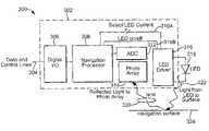
- FIG. 3is a block diagram illustrating major components of an optical pointing device 300 according to one embodiment of the present invention.
- Optical pointing device 300includes optical navigation integrated circuit (IC) 302 , light source 318 , and lens 320 .
- Optical navigation integrated circuit 302includes digital input/output circuitry 306 , navigation processor 308 , analog to digital converter (ADC) 312 , photo detector array (photo array) 314 , and LED driver circuit 316 .
- ADCanalog to digital converter
- light source 318emits light 322 onto navigation surface 324 , which is a desktop or other suitable surface, and reflected images are generated.
- light source 318includes one or more LED's, and is also referred to as LED 318 .
- Light source 318is controlled by LED driver circuit 316 , which is controlled by navigation processor 308 via control lines 310 A and 310 B.
- Control line 310 Bis used by navigation processor 308 to cause LED driver circuit 316 to be powered on and off, and correspondingly cause LED 318 to be powered on and off.
- Reflected light from surface 324is directed by lens 320 onto photo detector array 314 .
- Each photo detector in photo detector array 314provides a signal that varies in magnitude based upon the intensity of light incident on the photo detector.
- the signals from photo detector array 314are output to analog to digital converter 312 , which converts the signals into digital values of a suitable resolution (e.g., eight bits).
- the digital valuesrepresent a digital image or digital representation of the portion of the desktop or other navigation surface under optical pointing device 300 .
- the digital valuesare stored as frames within navigation processor 308 .
- the overall size of photo detector array 314is preferably large enough to receive an image having several features. Images of such spatial features produce translated patterns of pixel information as optical pointing device 300 moves over a surface. The number of photo detectors in array 314 and the frame rate at which their contents are captured and digitized cooperate to influence how fast optical pointing device 300 can be moved across a surface and still be tracked. Tracking is accomplished by navigation processor 308 by comparing a newly captured sample frame with a previously captured reference frame to ascertain the direction and amount of movement.
- the entire content of one of the framesis shifted by navigation processor 308 by a distance of one pixel successively in each of the eight directions allowed by a one pixel offset trial shift (one over, one over and one down, one down, one up, one up and one over, one over in the other direction, etc.). That adds up to eight trials. Also, since there might not have been any motion, a ninth trial “null shift” is also used. After each trial shift, those portions of the frames that overlap each other are subtracted by navigation processor 308 on a pixel by pixel basis, and the resulting differences are preferably squared and then summed to form a measure of similarity (correlation) within that region of overlap.
- trial shiftse.g., two over and one down
- the trial shift with the least difference (greatest correlation)can be taken as an indication of the motion between the two frames. That is, it provides raw movement information that may be scaled and or accumulated to provide movement information ( ⁇ X and ⁇ Y) of a convenient granularity and at a suitable rate of information exchange, which is output to a host device by digital input/output circuitry 306 on data and control lines 304 .
- Optical pointing device 300is also configured to receive data and control signals from a host device via data and control lines 304 .
- optical pointing device 300captures images at a particular frequency (e.g., 1500 frames per second), and navigation processor 308 uses control line 310 B to cause LED 318 to be pulsed on and off at the same frequency (e.g., 1500 pulses per second).
- a particular frequencye.g., 1500 frames per second
- navigation processor 308uses control line 310 B to cause LED 318 to be pulsed on and off at the same frequency (e.g., 1500 pulses per second).
- FIG. 4is a schematic diagram illustrating the LED driver circuit 316 shown in block form in FIG. 3 according to one embodiment of the present invention.
- the embodiment of LED driver circuit 316 shown in FIG. 4is identified by reference number “ 316 A.”
- Another embodiment of LED driver circuit 316is shown in FIG. 5 , is identified by reference number “ 316 B,” and is described below with reference to FIG. 5 .
- LED driver circuit 316 Aincludes drive circuit 430 and current monitor and control circuit 432 .
- Drive circuit 430includes current source 402 , and transistors 416 and 424 .
- Current monitor and control circuit 432includes current source 404 , transistor 418 , controller 410 , and current source 422 .
- transistors 418 and 424are matched transistors.
- transistors 416 , 418 , and 424are MOSFET's.
- circuit 316 Auses bipolar junction transistors.
- Current source 402is connected to control line 310 B for receiving an on/off control signal from navigation processor 308 ( FIG. 3 ), and is connected to control line 310 A for receiving a current selection signal from the navigation processor 308 .
- Current source 402is connected between a power supply 406 (V dd ) and the drain of transistor 416 .
- the drain of transistor 416is connected to the gate of transistor 416 , the gate of transistor 418 , and the gate of transistor 424 .
- the sources of transistors 416 , 418 , and 424are connected to ground 426 .
- Transistors 416 , 418 , and 424are connected in a current mirror configuration.
- Current source 404is connected to control line 310 A for receiving a current selection signal from the navigation processor 308 .
- Current source 404is connected between power supply 406 (V dd ) and the drain of transistor 418 .
- Controller 410includes a first input connected to the drain of transistor 424 via line 412 , and a second input connected to the drain of transistor 418 via line 414 .
- Controller 410includes an output connected to the current sources 404 and 422 via line 408 .
- Current source 422is connected between ground 426 and the line 420 connecting the gates of transistors 416 , 418 , and 424 .
- LED 318is connected between the power supply 406 (V dd ) and the drain of transistor 424 .
- circuit 316 Ais powered on and off by a navigation processor 308 via control line 310 B.
- current source 402provides a drive current (I drive ), which causes transistors 416 , 418 , and 424 to turn on and begin conducting current.
- Current source 404provides a bias current (I bias ).
- Current source 422provides a bleed current (I bleed ).
- the magnitude of the current provided by current sources 402 and 404is set by the navigation processor 308 via control line 310 A based on the desired level of current (I LED ) through the LED 318 .
- the navigation processor 308sets the bias current (I bias ) provided by current source 404 via control line 310 A to a first order, and the bias current (I bias ) provided by current source 404 is then adjusted to a second order by controller 410 as described in further detail below.
- the current (I LED ) through LED 318causes the LED 318 to emit light.
- current source 402stops providing the drive current (I drive ), transistors 416 , 418 , and 424 turn off, and the LED 318 stops emitting light.
- drive circuit 430 and current monitor and control circuit 432work in conjunction to drive the LED 318 with a current (I LED ) that is relatively constant regardless of the voltage (V d ) at the drain of the transistor 424 .
- the LED forward voltage (V f ) for the circuit 316 A shown in FIG. 3is equal to the power supply voltage (V dd ) minus the voltage (V d ) at the drain of transistor 424 .
- the voltage (V d ) at the drain of transistor 424is equal to the power supply voltage (V dd ) minus the LED forward voltage (V f ).
- controller 410monitors the gate (or base for a BJT) and the drain (or collector for a BJT) of transistor 424 , and uses that information to determine the current (I LED ) through the LED 318 . Controller 410 then compares the current (I LED ) through the LED 318 to a reference current, which is the current (I bias ) provided by current source 404 in the embodiment illustrated in FIG. 4 . In one embodiment, controller 410 compares the two currents (I LED and I bias ) by comparing the drain voltages (V dmirror and V d ) of transistors 418 and 424 .
- transistors 418 and 424have the gate node in common, when the drain voltages (V dmirror and V d ) of the two transistors 418 and 424 are equal, the current (I LED ) through the LED 318 will be proportional to the current (I bias ) provided by current source 404 .
- a deviation in the voltage (V d ) at the drain of transistor 424 from the voltage (V dmirror ) at the drain of transistor 418is an indication that the current (I LED ) through the LED 318 has deviated from being proportional to the current (I bias ) provided by current source 404 .
- Differences in the currents (I LED and I bias )may result from changes in the supply voltage (V dd ), temperature, or from choosing LED's with a range of forward voltages (V f ).
- the gate voltage (V g ) of transistor 424is indirectly sensed by controller 410 since the value of the gate voltage (V g ) of transistor 424 contributes to the drain voltages (V dmirror and V d ) of transistors 418 and 424 , which are directly sensed by controller 410 in the illustrated embodiment.
- Feedbackis used to adjust the gate (or base for a BJT) drive voltage (V g ) of transistor 424 to increase or decrease the current (I LED ) through the LED 318 until it matches the reference current (I bias ) provided by current source 404 .
- the feedback control loopwhich includes lines 408 , 412 , and 414 , and controller 410 , maintains the current (I LED ) through the LED 318 as proportional to the reference current (I bias ) provided by current source 404 over all operating conditions.
- navigation processor 308FIG. 3
- current monitor and control circuit 432adjusts the voltage (V g ) at the gate of transistor 424 to compensate for lower drain to source current of transistor 424 at lower drain voltages (V d ) of transistor 424 .
- controller 410senses the voltage (V d ) at the drain of transistor 424 and the voltage (V dmirror ) at the drain of transistor 418 , compares the two voltages (V d and V dmirror ) and attempts to equalize the two voltages (V d and V dmirror ).
- controller 410attempts to equalize the two voltages (V d and V dmirror ) by adjusting the voltage (V g ) at the gate of transistor 424 using a voltage control signal (V control ). Controller 410 outputs the voltage control signal (V control ) to current sources 404 and 422 via line 408 . Controller 410 causes current sources 404 and 422 to increase or decrease the amount of current being output using the voltage control signal (V control ).
- the voltage (V d ) at the drain of transistor 424may be below 0.1 volts, which pushes the transistor 424 into a region where the drain to source current (which is the same as the current (I LED ) through the LED 318 ) depends upon the drain to source voltage (V d ) of transistor 424 .
- the controller 410adjusts the voltage control signal (V control ) output on line 408 such that the current (I bleed ) provided by current source 422 is decreased, which increases the voltage (V g ) at the gate of transistor 424 .
- the increased voltage (V g ) at the gate of transistor 424acts to increase the drain to source current of transistor 424 , thereby compensating for the decrease in the drain to source current of transistor 424 that resulted from a drain voltage (V d ) of transistor 424 of less than 0.1 volts.
- the controller 410again acts to equalize the voltage (V d ) at the drain of transistor 424 and the voltage (V dmirror ) at the drain of transistor 418 .
- the controller 410adjusts the voltage control signal (V control ) output on line 408 to increase the current (I bleed ) provided by current source 422 , which decreases the voltage (V g ) at the gate of transistor 424 .
- the resulting decrease in the drain to source current of transistor 424offsets the increase in the drain to source current of transistor 424 resulting from the increase in the drain voltage (V d ) of transistor 424 .
- the voltage control signal (V control ) output by controller 410 on line 408is also provided to current source 404 to appropriately adjust the bias current (I bias ) provided by current source 404 in each of the above two cases (e.g., the case where the voltage (V d ) at the drain of transistor 424 is greater than 0.1 volts, or the case where the voltage (V d ) at the drain of transistor 424 is less than 0.1 volts) so that the voltage (V dmirror ) at the drain of transistor 418 can be effectively equalized to the voltage (V d ) at the drain of transistor 424 .
- the bias current (I bias ) provided by current source 404 and the bleed current (I bleed ) provided by current source 422are both controlled by the voltage control signal (V control ) output by the controller 410 on line 408 .
- the gain for controlling the bias current (I bias ) provided by current source 404is weaker than the gain for controlling the bleed current (I bleed ) provided by current source 422 , so that changes in the voltage (V d ) at the drain of transistor 424 will cause small changes in the bias current (I bias ) and larger changes in the bleed current (I bleed ).
- the voltage control signal (V control ) output by controller 410 on line 408is only used to control the bleed current (I bleed ) provided by current source 422 , and not the bias current (I bias ) provided by current source 404 , so that the bias current (I bias ) remains fixed.
- a purpose of the adjustment of the bias current (I bias ) provided by current source 404is to get the voltage (V dmirror ) at the drain of transistor 418 in the range near the voltage (V d ) at the drain of transistor 424 .
- the voltage (V dmirror ) at the drain of transistor 418 and the voltage (V d ) at the drain of transistor 424could end up being very far apart due to wafer processing variations, such as transistor mismatch.
- the adjustment of the bias current (I bias ) by the voltage control signal (V control ) output by controller 410helps to bring the voltage (V d mirror) at the drain of transistor 418 closer to an optimum starting point.
- the controller 410places the voltage (V dmirror ) at the drain of transistor 418 at a good starting point.
- the bleed current (I bleed ) provided by current source 422is adjusted by controller 410 to make the voltage (V d ) at the drain of transistor 424 equal to the voltage (V dmirror ) at the drain of transistor 418 .
- the controller 410makes small adjustments (i.e., low gain adjustments) to the bias current (I bias ) provided by current source 404 to bring the voltages (V d and V dmirror ) in range, and the controller 410 makes larger adjustments (i.e., higher gain adjustments) to the bleed current (I bleed ) provided by current source 422 to make the voltages (V d and V dmirror ) equal to each other.
- controller 410is a digital controller. In another form of the invention controller 410 is an analog controller. In one embodiment, the analog controller is an operational amplifier.
- FIG. 5is a schematic diagram illustrating the LED driver circuit 316 shown in block form in FIG. 3 according to another embodiment of the present invention, wherein the controller 410 is implemented with an operational amplifier (opamp) 502 .
- the LED driver circuit 316 B shown in FIG. 5is configured in the same manner as the circuit 316 A shown in FIG. 4 and functions in the same manner as described above with reference to FIG. 4 , but the controller 410 is shown in FIG. 5 as an operational amplifier 502 .
- optical pointing device 300( FIG. 3 ) is an optical mouse for a desktop personal computer, workstation, portable computer, or other device. In another embodiment, optical pointing device 300 is configured as an optical fingerprint sensing pointing device, or other pointing device.
- optical pointing device 300may be implemented in hardware, software, firmware, or any combination thereof.
- the implementationmay be via a microprocessor, programmable logic device, or state machine.
- Components of the present inventionmay reside in software on one or more computer-readable mediums.
- the term computer-readable medium as used hereinis defined to include any kind of memory, volatile or non-volatile, such as floppy disks, hard disks, CD-ROMs, flash memory, read-only memory (ROM), and random access memory.
- Embodiments of the present inventionprovide several advantages over prior art LED driver circuits.
- One embodiment of LED driver circuit 316provides tight control over the range of illumination of the LED 318 over various operating modes and operating conditions, and during transitions between various operating modes, such as sleep modes.
- One embodiment of LED driver circuit 316is completely integrated in an integrated circuit, and no external components, such as a series resistor used in some prior art driver circuits, need to be added by the customer after production.
- LED driver circuit 316according to one form of the invention also provides continual tuning or adjustment of the LED current after production and during normal operation, which provides an advantage over prior art LED driver circuits that may use a series resistor or fuses to provide a one time tuning function during production.
Landscapes
- Engineering & Computer Science (AREA)
- General Engineering & Computer Science (AREA)
- Theoretical Computer Science (AREA)
- Human Computer Interaction (AREA)
- Physics & Mathematics (AREA)
- General Physics & Mathematics (AREA)
- Led Devices (AREA)
Abstract
Description
Claims (5)
Priority Applications (1)
| Application Number | Priority Date | Filing Date | Title |
|---|---|---|---|
| US11/639,703US7557332B2 (en) | 2004-03-08 | 2006-12-15 | Driver circuit for driving a light source of an optical pointing device |
Applications Claiming Priority (2)
| Application Number | Priority Date | Filing Date | Title |
|---|---|---|---|
| US10/795,689US7170335B2 (en) | 2004-03-08 | 2004-03-08 | Driver circuit for driving a light source of an optical pointing device |
| US11/639,703US7557332B2 (en) | 2004-03-08 | 2006-12-15 | Driver circuit for driving a light source of an optical pointing device |
Related Parent Applications (2)
| Application Number | Title | Priority Date | Filing Date |
|---|---|---|---|
| US10/795,689DivisionUS7170335B2 (en) | 2004-03-08 | 2004-03-08 | Driver circuit for driving a light source of an optical pointing device |
| US12/481,235Continuation-In-PartUS7802426B2 (en) | 2008-04-09 | 2009-06-09 | System and method for rapid isothermal gas expansion and compression for energy storage |
Publications (2)
| Publication Number | Publication Date |
|---|---|
| US20070091067A1 US20070091067A1 (en) | 2007-04-26 |
| US7557332B2true US7557332B2 (en) | 2009-07-07 |
Family
ID=34912505
Family Applications (2)
| Application Number | Title | Priority Date | Filing Date |
|---|---|---|---|
| US10/795,689Expired - LifetimeUS7170335B2 (en) | 2004-03-08 | 2004-03-08 | Driver circuit for driving a light source of an optical pointing device |
| US11/639,703Expired - LifetimeUS7557332B2 (en) | 2004-03-08 | 2006-12-15 | Driver circuit for driving a light source of an optical pointing device |
Family Applications Before (1)
| Application Number | Title | Priority Date | Filing Date |
|---|---|---|---|
| US10/795,689Expired - LifetimeUS7170335B2 (en) | 2004-03-08 | 2004-03-08 | Driver circuit for driving a light source of an optical pointing device |
Country Status (1)
| Country | Link |
|---|---|
| US (2) | US7170335B2 (en) |
Cited By (2)
| Publication number | Priority date | Publication date | Assignee | Title |
|---|---|---|---|---|
| US20120068607A1 (en)* | 2010-09-17 | 2012-03-22 | Simplexgrinnell Lp | Supervision for a light display device |
| US20200091678A1 (en)* | 2018-09-18 | 2020-03-19 | Ampliphy Technologies Limited | Accurate current mirror circuit in low voltage headroom applied to laser drivers |
Families Citing this family (12)
| Publication number | Priority date | Publication date | Assignee | Title |
|---|---|---|---|---|
| US9019377B2 (en)* | 2007-02-13 | 2015-04-28 | Fujitsu Ten Limited | Drive recorder, drive recorder system, vehicle-mounted video recording apparatus, and vehicle-mounted video recording method |
| DE102007048243B3 (en)* | 2007-10-08 | 2009-04-30 | Texas Instruments Deutschland Gmbh | Advanced current mirror for LED driver applications |
| US8581810B2 (en)* | 2008-03-11 | 2013-11-12 | Atmel Corporation | Methods and circuits for self-calibrating controller |
| US8493300B2 (en)* | 2008-03-11 | 2013-07-23 | Atmel Corporation | Architecture and technique for inter-chip communication |
| US8378957B2 (en)* | 2008-04-28 | 2013-02-19 | Atmel Corporation | Methods and circuits for triode region detection |
| US8314572B2 (en)* | 2008-06-24 | 2012-11-20 | Atmel Corporation | Apparatus and methodology for enhancing efficiency of a power distribution system having power factor correction capability by using a self-calibrating controller |
| US8441199B2 (en)* | 2009-03-23 | 2013-05-14 | Atmel Corporation | Method and apparatus for an intelligent light emitting diode driver having power factor correction capability |
| US8416191B2 (en)* | 2009-09-30 | 2013-04-09 | Avago Technologies Ecbu Ip (Singapore) Pte. Ltd. | Large depth of field navigation input devices and methods |
| TW201133121A (en)* | 2010-03-31 | 2011-10-01 | Acer Inc | Projection device and projection light source control method thereof |
| CN103208252B (en)* | 2012-01-11 | 2017-05-24 | 深圳富泰宏精密工业有限公司 | Display screen light-emitting diode (LED) control circuit |
| WO2016135824A1 (en)* | 2015-02-23 | 2016-09-01 | 三菱電機株式会社 | Optical receiving device |
| US10178727B2 (en)* | 2015-02-27 | 2019-01-08 | Diodes Incorporated | Analog and digital dimming control for LED driver |
Citations (28)
| Publication number | Priority date | Publication date | Assignee | Title |
|---|---|---|---|---|
| US4967417A (en) | 1988-07-12 | 1990-10-30 | Canon Kabushiki Kaisha | Laser driving device provided with two reference signal sources, and optical information recording apparatus using the same device |
| US5134323A (en) | 1990-08-03 | 1992-07-28 | Congdon James E | Three terminal noninverting transistor switch |
| US5305337A (en) | 1991-03-15 | 1994-04-19 | Asahi Kogaku Kogyo Kabushiki Kaisha | Laser controller |
| US5802089A (en) | 1996-10-22 | 1998-09-01 | Maxim Integrated Products, Inc. | Laser diode driver having automatic power control with smooth enable function |
| US5936986A (en) | 1996-07-30 | 1999-08-10 | Bayer Corporation | Methods and apparatus for driving a laser diode |
| US5966395A (en) | 1996-11-29 | 1999-10-12 | Fuji Xerox Co., Ltd. | Semiconductor laser drive device and image recording device |
| US6265832B1 (en) | 1998-08-06 | 2001-07-24 | Mannesmann Vdo Ag | Driving circuit for light-emitting diodes |
| US6320890B1 (en) | 1999-01-29 | 2001-11-20 | Kabushiki Kaisha Toshiba | Laser driving circuit capable of stably controlling laser output |
| US20010043093A1 (en) | 2000-05-16 | 2001-11-22 | Shigeyuki Sakura | Led driving circuit and optical transmitting module |
| US6392215B1 (en) | 1999-09-20 | 2002-05-21 | International Business Machines Corporation | Laser diode driving circuit |
| US6408087B1 (en) | 1998-01-13 | 2002-06-18 | Stmicroelectronics, Inc. | Capacitive semiconductor user input device |
| US6496526B1 (en) | 2000-10-18 | 2002-12-17 | Xerox Corporation | Current switching driver with controlled bias and ON states |
| US20030039280A1 (en) | 2001-06-07 | 2003-02-27 | Joseph Mangano | Method and apparatus for driving laser diode sources |
| US6555966B2 (en) | 2001-05-25 | 2003-04-29 | Watt Stopper, Inc. | Closed loop lighting control system |
| US20030156609A1 (en) | 2002-02-15 | 2003-08-21 | Chia-Ming Tsai | Driving control circuit for ligth-emitting device |
| US6631218B2 (en) | 1998-03-18 | 2003-10-07 | Agilent Technologies, Inc. | CMOS digital optical navigation chip |
| US20030235062A1 (en) | 2002-06-20 | 2003-12-25 | Lajos Burgyan | High efficiency led driver |
| US6674269B1 (en) | 2002-09-23 | 2004-01-06 | Xerox Corporation | Light emitting diode driver and image forming device including the same |
| US6683490B2 (en) | 2001-10-25 | 2004-01-27 | Kabushiki Kaisha Toshiba | Temperature dependent constant-current generating circuit |
| US6744795B2 (en) | 2002-07-11 | 2004-06-01 | Intel Corporation | Laser driver circuit and system |
| US20040114649A1 (en) | 2002-12-16 | 2004-06-17 | Bhushan Asuri | Laser driver circuit and system |
| US6762636B1 (en) | 2001-12-11 | 2004-07-13 | Cypress Semiconductor Corp. | Circuit and method for adjusting duty cycle of a high speed, low swing output signal |
| US20040178778A1 (en) | 2002-12-10 | 2004-09-16 | Stmicroelectronics Pvt. Ltd. | Integrated low dropout linear voltage regulator with improved current limiting |
| US6797937B2 (en)* | 2001-07-24 | 2004-09-28 | Agilent Technologies, Inc. | System and method for reducing power consumption in an optical screen pointing device |
| US6826215B2 (en) | 2000-02-22 | 2004-11-30 | Yamaha Corporation | Laser diode driving circuit |
| US20040264526A1 (en) | 2003-05-06 | 2004-12-30 | Karl Schrodinger | Electrical circuit for a directly modulated semiconductor radiation source |
| US20050093488A1 (en) | 2003-10-28 | 2005-05-05 | Mao-Chi Hung | Method and apparatus for controlling driving current of illumination source in a display system |
| US6956408B2 (en) | 2003-10-02 | 2005-10-18 | Infineon Technologies Ag | Drive device for a light-emitting component |
- 2004
- 2004-03-08USUS10/795,689patent/US7170335B2/ennot_activeExpired - Lifetime
- 2006
- 2006-12-15USUS11/639,703patent/US7557332B2/ennot_activeExpired - Lifetime
Patent Citations (28)
| Publication number | Priority date | Publication date | Assignee | Title |
|---|---|---|---|---|
| US4967417A (en) | 1988-07-12 | 1990-10-30 | Canon Kabushiki Kaisha | Laser driving device provided with two reference signal sources, and optical information recording apparatus using the same device |
| US5134323A (en) | 1990-08-03 | 1992-07-28 | Congdon James E | Three terminal noninverting transistor switch |
| US5305337A (en) | 1991-03-15 | 1994-04-19 | Asahi Kogaku Kogyo Kabushiki Kaisha | Laser controller |
| US5936986A (en) | 1996-07-30 | 1999-08-10 | Bayer Corporation | Methods and apparatus for driving a laser diode |
| US5802089A (en) | 1996-10-22 | 1998-09-01 | Maxim Integrated Products, Inc. | Laser diode driver having automatic power control with smooth enable function |
| US5966395A (en) | 1996-11-29 | 1999-10-12 | Fuji Xerox Co., Ltd. | Semiconductor laser drive device and image recording device |
| US6408087B1 (en) | 1998-01-13 | 2002-06-18 | Stmicroelectronics, Inc. | Capacitive semiconductor user input device |
| US6631218B2 (en) | 1998-03-18 | 2003-10-07 | Agilent Technologies, Inc. | CMOS digital optical navigation chip |
| US6265832B1 (en) | 1998-08-06 | 2001-07-24 | Mannesmann Vdo Ag | Driving circuit for light-emitting diodes |
| US6320890B1 (en) | 1999-01-29 | 2001-11-20 | Kabushiki Kaisha Toshiba | Laser driving circuit capable of stably controlling laser output |
| US6392215B1 (en) | 1999-09-20 | 2002-05-21 | International Business Machines Corporation | Laser diode driving circuit |
| US6826215B2 (en) | 2000-02-22 | 2004-11-30 | Yamaha Corporation | Laser diode driving circuit |
| US20010043093A1 (en) | 2000-05-16 | 2001-11-22 | Shigeyuki Sakura | Led driving circuit and optical transmitting module |
| US6496526B1 (en) | 2000-10-18 | 2002-12-17 | Xerox Corporation | Current switching driver with controlled bias and ON states |
| US6555966B2 (en) | 2001-05-25 | 2003-04-29 | Watt Stopper, Inc. | Closed loop lighting control system |
| US20030039280A1 (en) | 2001-06-07 | 2003-02-27 | Joseph Mangano | Method and apparatus for driving laser diode sources |
| US6797937B2 (en)* | 2001-07-24 | 2004-09-28 | Agilent Technologies, Inc. | System and method for reducing power consumption in an optical screen pointing device |
| US6683490B2 (en) | 2001-10-25 | 2004-01-27 | Kabushiki Kaisha Toshiba | Temperature dependent constant-current generating circuit |
| US6762636B1 (en) | 2001-12-11 | 2004-07-13 | Cypress Semiconductor Corp. | Circuit and method for adjusting duty cycle of a high speed, low swing output signal |
| US20030156609A1 (en) | 2002-02-15 | 2003-08-21 | Chia-Ming Tsai | Driving control circuit for ligth-emitting device |
| US20030235062A1 (en) | 2002-06-20 | 2003-12-25 | Lajos Burgyan | High efficiency led driver |
| US6744795B2 (en) | 2002-07-11 | 2004-06-01 | Intel Corporation | Laser driver circuit and system |
| US6674269B1 (en) | 2002-09-23 | 2004-01-06 | Xerox Corporation | Light emitting diode driver and image forming device including the same |
| US20040178778A1 (en) | 2002-12-10 | 2004-09-16 | Stmicroelectronics Pvt. Ltd. | Integrated low dropout linear voltage regulator with improved current limiting |
| US20040114649A1 (en) | 2002-12-16 | 2004-06-17 | Bhushan Asuri | Laser driver circuit and system |
| US20040264526A1 (en) | 2003-05-06 | 2004-12-30 | Karl Schrodinger | Electrical circuit for a directly modulated semiconductor radiation source |
| US6956408B2 (en) | 2003-10-02 | 2005-10-18 | Infineon Technologies Ag | Drive device for a light-emitting component |
| US20050093488A1 (en) | 2003-10-28 | 2005-05-05 | Mao-Chi Hung | Method and apparatus for controlling driving current of illumination source in a display system |
Cited By (4)
| Publication number | Priority date | Publication date | Assignee | Title |
|---|---|---|---|---|
| US20120068607A1 (en)* | 2010-09-17 | 2012-03-22 | Simplexgrinnell Lp | Supervision for a light display device |
| US8614550B2 (en)* | 2010-09-17 | 2013-12-24 | Simplexgrinnell Lp | Supervision for a light display device |
| US20200091678A1 (en)* | 2018-09-18 | 2020-03-19 | Ampliphy Technologies Limited | Accurate current mirror circuit in low voltage headroom applied to laser drivers |
| US10756509B2 (en)* | 2018-09-18 | 2020-08-25 | Ampliphy Technologies Limited | Accurate current mirror circuit in low voltage headroom applied to laser drivers |
Also Published As
| Publication number | Publication date |
|---|---|
| US7170335B2 (en) | 2007-01-30 |
| US20050194915A1 (en) | 2005-09-08 |
| US20070091067A1 (en) | 2007-04-26 |
Similar Documents
| Publication | Publication Date | Title |
|---|---|---|
| US7557332B2 (en) | Driver circuit for driving a light source of an optical pointing device | |
| US7106285B2 (en) | Method and apparatus for controlling an active matrix display | |
| US7545350B2 (en) | Active-matrix organic electroluminescent display device | |
| US7317447B2 (en) | Pointing device with adaptive illumination level | |
| JP5096516B2 (en) | Optical sensing circuit, touch panel including the same, and driving method of optical sensing circuit | |
| KR100975870B1 (en) | Touch panel comprising an optical sensing circuit, its driving method and the optical sensing circuit | |
| US5144117A (en) | Illumination type optical recorded information reading device | |
| US8658958B2 (en) | Light sensing circuit having programmable current source and method thereof | |
| US7399953B2 (en) | Light source control in optical pointing device | |
| US5414280A (en) | Current driven voltage sensed laser drive (CDVS LDD) | |
| CN102122485B (en) | Display apparatus, light detection method and electronic apparatus | |
| US9341709B2 (en) | Image sensing device and focal plane array device using frequency conversion for real-time terahertz imaging | |
| JP4854410B2 (en) | Semiconductor device | |
| KR20080025897A (en) | Optical pointing device and power supply voltage supply semiconductor device for optical pointing | |
| KR20050031675A (en) | Temperature sensor for sensing current temperature and generating digital data corresponding to current temperature | |
| US7480320B2 (en) | Semiconductor laser driving device, semiconductor laser driving method, and image forming apparatus using semiconductor laser driving device | |
| WO2019091268A1 (en) | Electric signal detection module, drive method, pixel circuit and display apparatus | |
| US6392215B1 (en) | Laser diode driving circuit | |
| JP2008022412A (en) | Electronic circuit, electro-optical apparatus and electronic device comprising the same | |
| US7812834B2 (en) | DC stabilization circuit for organic electroluminescent display device and power supply using the same | |
| US20050264346A1 (en) | Generator for supplying reference voltage and reference current of stable level regardless of temperature variation | |
| JP3843666B2 (en) | Laser diode drive circuit and image recording apparatus | |
| KR20230118222A (en) | Display device and electronic apparatus including the same | |
| US10431623B2 (en) | Method applied to BJT pixel of image sensor apparatus and image sensor apparatus | |
| CN113449579B (en) | Image sensing method, system and circuit |
Legal Events
| Date | Code | Title | Description |
|---|---|---|---|
| STCF | Information on status: patent grant | Free format text:PATENTED CASE | |
| FPAY | Fee payment | Year of fee payment:4 | |
| AS | Assignment | Owner name:AVAGO TECHNOLOGIES GENERAL IP (SINGAPORE) PTE. LTD Free format text:MERGER;ASSIGNOR:AVAGO TECHNOLOGIES ECBU IP (SINGAPORE) PTE. LTD.;REEL/FRAME:030369/0528 Effective date:20121030 | |
| AS | Assignment | Owner name:DEUTSCHE BANK AG NEW YORK BRANCH, AS COLLATERAL AGENT, NEW YORK Free format text:PATENT SECURITY AGREEMENT;ASSIGNOR:AVAGO TECHNOLOGIES GENERAL IP (SINGAPORE) PTE. LTD.;REEL/FRAME:032851/0001 Effective date:20140506 Owner name:DEUTSCHE BANK AG NEW YORK BRANCH, AS COLLATERAL AG Free format text:PATENT SECURITY AGREEMENT;ASSIGNOR:AVAGO TECHNOLOGIES GENERAL IP (SINGAPORE) PTE. LTD.;REEL/FRAME:032851/0001 Effective date:20140506 | |
| AS | Assignment | Owner name:AVAGO TECHNOLOGIES GENERAL IP (SINGAPORE) PTE. LTD., SINGAPORE Free format text:TERMINATION AND RELEASE OF SECURITY INTEREST IN PATENT RIGHTS (RELEASES RF 032851-0001);ASSIGNOR:DEUTSCHE BANK AG NEW YORK BRANCH, AS COLLATERAL AGENT;REEL/FRAME:037689/0001 Effective date:20160201 Owner name:AVAGO TECHNOLOGIES GENERAL IP (SINGAPORE) PTE. LTD Free format text:TERMINATION AND RELEASE OF SECURITY INTEREST IN PATENT RIGHTS (RELEASES RF 032851-0001);ASSIGNOR:DEUTSCHE BANK AG NEW YORK BRANCH, AS COLLATERAL AGENT;REEL/FRAME:037689/0001 Effective date:20160201 | |
| AS | Assignment | Owner name:BANK OF AMERICA, N.A., AS COLLATERAL AGENT, NORTH CAROLINA Free format text:PATENT SECURITY AGREEMENT;ASSIGNOR:AVAGO TECHNOLOGIES GENERAL IP (SINGAPORE) PTE. LTD.;REEL/FRAME:037808/0001 Effective date:20160201 Owner name:BANK OF AMERICA, N.A., AS COLLATERAL AGENT, NORTH Free format text:PATENT SECURITY AGREEMENT;ASSIGNOR:AVAGO TECHNOLOGIES GENERAL IP (SINGAPORE) PTE. LTD.;REEL/FRAME:037808/0001 Effective date:20160201 | |
| AS | Assignment | Owner name:PIXART IMAGING INC., TAIWAN Free format text:ASSIGNMENT OF ASSIGNORS INTEREST;ASSIGNOR:AVAGO TECHNOLOGIES GENERAL IP (SINGAPORE) PTE. LTD.;REEL/FRAME:039788/0572 Effective date:20160805 | |
| AS | Assignment | Owner name:AVAGO TECHNOLOGIES GENERAL IP (SINGAPORE) PTE. LTD., SINGAPORE Free format text:TERMINATION AND RELEASE OF SECURITY INTEREST IN PATENTS;ASSIGNOR:BANK OF AMERICA, N.A., AS COLLATERAL AGENT;REEL/FRAME:039862/0129 Effective date:20160826 Owner name:AVAGO TECHNOLOGIES GENERAL IP (SINGAPORE) PTE. LTD Free format text:TERMINATION AND RELEASE OF SECURITY INTEREST IN PATENTS;ASSIGNOR:BANK OF AMERICA, N.A., AS COLLATERAL AGENT;REEL/FRAME:039862/0129 Effective date:20160826 | |
| FPAY | Fee payment | Year of fee payment:8 | |
| AS | Assignment | Owner name:AVAGO TECHNOLOGIES GENERAL IP (SINGAPORE) PTE. LTD., SINGAPORE Free format text:TERMINATION AND RELEASE OF SECURITY INTEREST IN PATENTS;ASSIGNOR:BANK OF AMERICA, N.A., AS COLLATERAL AGENT;REEL/FRAME:041710/0001 Effective date:20170119 Owner name:AVAGO TECHNOLOGIES GENERAL IP (SINGAPORE) PTE. LTD Free format text:TERMINATION AND RELEASE OF SECURITY INTEREST IN PATENTS;ASSIGNOR:BANK OF AMERICA, N.A., AS COLLATERAL AGENT;REEL/FRAME:041710/0001 Effective date:20170119 | |
| MAFP | Maintenance fee payment | Free format text:PAYMENT OF MAINTENANCE FEE, 12TH YEAR, LARGE ENTITY (ORIGINAL EVENT CODE: M1553); ENTITY STATUS OF PATENT OWNER: LARGE ENTITY Year of fee payment:12 |