US7556644B2 - Flexible stent - Google Patents
Flexible stentDownload PDFInfo
- Publication number
- US7556644B2 US7556644B2US11/749,306US74930607AUS7556644B2US 7556644 B2US7556644 B2US 7556644B2US 74930607 AUS74930607 AUS 74930607AUS 7556644 B2US7556644 B2US 7556644B2
- Authority
- US
- United States
- Prior art keywords
- helical
- strut
- stent
- elements
- axis
- Prior art date
- Legal status (The legal status is an assumption and is not a legal conclusion. Google has not performed a legal analysis and makes no representation as to the accuracy of the status listed.)
- Expired - Lifetime
Links
Images


Classifications
- A—HUMAN NECESSITIES
- A61—MEDICAL OR VETERINARY SCIENCE; HYGIENE
- A61F—FILTERS IMPLANTABLE INTO BLOOD VESSELS; PROSTHESES; DEVICES PROVIDING PATENCY TO, OR PREVENTING COLLAPSING OF, TUBULAR STRUCTURES OF THE BODY, e.g. STENTS; ORTHOPAEDIC, NURSING OR CONTRACEPTIVE DEVICES; FOMENTATION; TREATMENT OR PROTECTION OF EYES OR EARS; BANDAGES, DRESSINGS OR ABSORBENT PADS; FIRST-AID KITS
- A61F2/00—Filters implantable into blood vessels; Prostheses, i.e. artificial substitutes or replacements for parts of the body; Appliances for connecting them with the body; Devices providing patency to, or preventing collapsing of, tubular structures of the body, e.g. stents
- A61F2/82—Devices providing patency to, or preventing collapsing of, tubular structures of the body, e.g. stents
- A61F2/86—Stents in a form characterised by the wire-like elements; Stents in the form characterised by a net-like or mesh-like structure
- A61F2/88—Stents in a form characterised by the wire-like elements; Stents in the form characterised by a net-like or mesh-like structure the wire-like elements formed as helical or spiral coils
- A—HUMAN NECESSITIES
- A61—MEDICAL OR VETERINARY SCIENCE; HYGIENE
- A61F—FILTERS IMPLANTABLE INTO BLOOD VESSELS; PROSTHESES; DEVICES PROVIDING PATENCY TO, OR PREVENTING COLLAPSING OF, TUBULAR STRUCTURES OF THE BODY, e.g. STENTS; ORTHOPAEDIC, NURSING OR CONTRACEPTIVE DEVICES; FOMENTATION; TREATMENT OR PROTECTION OF EYES OR EARS; BANDAGES, DRESSINGS OR ABSORBENT PADS; FIRST-AID KITS
- A61F2/00—Filters implantable into blood vessels; Prostheses, i.e. artificial substitutes or replacements for parts of the body; Appliances for connecting them with the body; Devices providing patency to, or preventing collapsing of, tubular structures of the body, e.g. stents
- A61F2/02—Prostheses implantable into the body
- A61F2/04—Hollow or tubular parts of organs, e.g. bladders, tracheae, bronchi or bile ducts
- A61F2/06—Blood vessels
- A61F2/07—Stent-grafts
- A—HUMAN NECESSITIES
- A61—MEDICAL OR VETERINARY SCIENCE; HYGIENE
- A61F—FILTERS IMPLANTABLE INTO BLOOD VESSELS; PROSTHESES; DEVICES PROVIDING PATENCY TO, OR PREVENTING COLLAPSING OF, TUBULAR STRUCTURES OF THE BODY, e.g. STENTS; ORTHOPAEDIC, NURSING OR CONTRACEPTIVE DEVICES; FOMENTATION; TREATMENT OR PROTECTION OF EYES OR EARS; BANDAGES, DRESSINGS OR ABSORBENT PADS; FIRST-AID KITS
- A61F2/00—Filters implantable into blood vessels; Prostheses, i.e. artificial substitutes or replacements for parts of the body; Appliances for connecting them with the body; Devices providing patency to, or preventing collapsing of, tubular structures of the body, e.g. stents
- A61F2/82—Devices providing patency to, or preventing collapsing of, tubular structures of the body, e.g. stents
- A61F2/86—Stents in a form characterised by the wire-like elements; Stents in the form characterised by a net-like or mesh-like structure
- A61F2/90—Stents in a form characterised by the wire-like elements; Stents in the form characterised by a net-like or mesh-like structure characterised by a net-like or mesh-like structure
- A61F2/91—Stents in a form characterised by the wire-like elements; Stents in the form characterised by a net-like or mesh-like structure characterised by a net-like or mesh-like structure made from perforated sheets or tubes, e.g. perforated by laser cuts or etched holes
- A61F2/915—Stents in a form characterised by the wire-like elements; Stents in the form characterised by a net-like or mesh-like structure characterised by a net-like or mesh-like structure made from perforated sheets or tubes, e.g. perforated by laser cuts or etched holes with bands having a meander structure, adjacent bands being connected to each other
- A—HUMAN NECESSITIES
- A61—MEDICAL OR VETERINARY SCIENCE; HYGIENE
- A61F—FILTERS IMPLANTABLE INTO BLOOD VESSELS; PROSTHESES; DEVICES PROVIDING PATENCY TO, OR PREVENTING COLLAPSING OF, TUBULAR STRUCTURES OF THE BODY, e.g. STENTS; ORTHOPAEDIC, NURSING OR CONTRACEPTIVE DEVICES; FOMENTATION; TREATMENT OR PROTECTION OF EYES OR EARS; BANDAGES, DRESSINGS OR ABSORBENT PADS; FIRST-AID KITS
- A61F2/00—Filters implantable into blood vessels; Prostheses, i.e. artificial substitutes or replacements for parts of the body; Appliances for connecting them with the body; Devices providing patency to, or preventing collapsing of, tubular structures of the body, e.g. stents
- A61F2/95—Instruments specially adapted for placement or removal of stents or stent-grafts
- A61F2/962—Instruments specially adapted for placement or removal of stents or stent-grafts having an outer sleeve
- A61F2/966—Instruments specially adapted for placement or removal of stents or stent-grafts having an outer sleeve with relative longitudinal movement between outer sleeve and prosthesis, e.g. using a push rod
- A—HUMAN NECESSITIES
- A61—MEDICAL OR VETERINARY SCIENCE; HYGIENE
- A61F—FILTERS IMPLANTABLE INTO BLOOD VESSELS; PROSTHESES; DEVICES PROVIDING PATENCY TO, OR PREVENTING COLLAPSING OF, TUBULAR STRUCTURES OF THE BODY, e.g. STENTS; ORTHOPAEDIC, NURSING OR CONTRACEPTIVE DEVICES; FOMENTATION; TREATMENT OR PROTECTION OF EYES OR EARS; BANDAGES, DRESSINGS OR ABSORBENT PADS; FIRST-AID KITS
- A61F2/00—Filters implantable into blood vessels; Prostheses, i.e. artificial substitutes or replacements for parts of the body; Appliances for connecting them with the body; Devices providing patency to, or preventing collapsing of, tubular structures of the body, e.g. stents
- A61F2/82—Devices providing patency to, or preventing collapsing of, tubular structures of the body, e.g. stents
- A61F2/86—Stents in a form characterised by the wire-like elements; Stents in the form characterised by a net-like or mesh-like structure
- A61F2/90—Stents in a form characterised by the wire-like elements; Stents in the form characterised by a net-like or mesh-like structure characterised by a net-like or mesh-like structure
- A61F2/91—Stents in a form characterised by the wire-like elements; Stents in the form characterised by a net-like or mesh-like structure characterised by a net-like or mesh-like structure made from perforated sheets or tubes, e.g. perforated by laser cuts or etched holes
- A61F2/915—Stents in a form characterised by the wire-like elements; Stents in the form characterised by a net-like or mesh-like structure characterised by a net-like or mesh-like structure made from perforated sheets or tubes, e.g. perforated by laser cuts or etched holes with bands having a meander structure, adjacent bands being connected to each other
- A61F2002/91525—Stents in a form characterised by the wire-like elements; Stents in the form characterised by a net-like or mesh-like structure characterised by a net-like or mesh-like structure made from perforated sheets or tubes, e.g. perforated by laser cuts or etched holes with bands having a meander structure, adjacent bands being connected to each other within the whole structure different bands showing different meander characteristics, e.g. frequency or amplitude
- A—HUMAN NECESSITIES
- A61—MEDICAL OR VETERINARY SCIENCE; HYGIENE
- A61F—FILTERS IMPLANTABLE INTO BLOOD VESSELS; PROSTHESES; DEVICES PROVIDING PATENCY TO, OR PREVENTING COLLAPSING OF, TUBULAR STRUCTURES OF THE BODY, e.g. STENTS; ORTHOPAEDIC, NURSING OR CONTRACEPTIVE DEVICES; FOMENTATION; TREATMENT OR PROTECTION OF EYES OR EARS; BANDAGES, DRESSINGS OR ABSORBENT PADS; FIRST-AID KITS
- A61F2/00—Filters implantable into blood vessels; Prostheses, i.e. artificial substitutes or replacements for parts of the body; Appliances for connecting them with the body; Devices providing patency to, or preventing collapsing of, tubular structures of the body, e.g. stents
- A61F2/82—Devices providing patency to, or preventing collapsing of, tubular structures of the body, e.g. stents
- A61F2/86—Stents in a form characterised by the wire-like elements; Stents in the form characterised by a net-like or mesh-like structure
- A61F2/90—Stents in a form characterised by the wire-like elements; Stents in the form characterised by a net-like or mesh-like structure characterised by a net-like or mesh-like structure
- A61F2/91—Stents in a form characterised by the wire-like elements; Stents in the form characterised by a net-like or mesh-like structure characterised by a net-like or mesh-like structure made from perforated sheets or tubes, e.g. perforated by laser cuts or etched holes
- A61F2/915—Stents in a form characterised by the wire-like elements; Stents in the form characterised by a net-like or mesh-like structure characterised by a net-like or mesh-like structure made from perforated sheets or tubes, e.g. perforated by laser cuts or etched holes with bands having a meander structure, adjacent bands being connected to each other
- A61F2002/91533—Stents in a form characterised by the wire-like elements; Stents in the form characterised by a net-like or mesh-like structure characterised by a net-like or mesh-like structure made from perforated sheets or tubes, e.g. perforated by laser cuts or etched holes with bands having a meander structure, adjacent bands being connected to each other characterised by the phase between adjacent bands
- A—HUMAN NECESSITIES
- A61—MEDICAL OR VETERINARY SCIENCE; HYGIENE
- A61F—FILTERS IMPLANTABLE INTO BLOOD VESSELS; PROSTHESES; DEVICES PROVIDING PATENCY TO, OR PREVENTING COLLAPSING OF, TUBULAR STRUCTURES OF THE BODY, e.g. STENTS; ORTHOPAEDIC, NURSING OR CONTRACEPTIVE DEVICES; FOMENTATION; TREATMENT OR PROTECTION OF EYES OR EARS; BANDAGES, DRESSINGS OR ABSORBENT PADS; FIRST-AID KITS
- A61F2/00—Filters implantable into blood vessels; Prostheses, i.e. artificial substitutes or replacements for parts of the body; Appliances for connecting them with the body; Devices providing patency to, or preventing collapsing of, tubular structures of the body, e.g. stents
- A61F2/82—Devices providing patency to, or preventing collapsing of, tubular structures of the body, e.g. stents
- A61F2/86—Stents in a form characterised by the wire-like elements; Stents in the form characterised by a net-like or mesh-like structure
- A61F2/90—Stents in a form characterised by the wire-like elements; Stents in the form characterised by a net-like or mesh-like structure characterised by a net-like or mesh-like structure
- A61F2/91—Stents in a form characterised by the wire-like elements; Stents in the form characterised by a net-like or mesh-like structure characterised by a net-like or mesh-like structure made from perforated sheets or tubes, e.g. perforated by laser cuts or etched holes
- A61F2/915—Stents in a form characterised by the wire-like elements; Stents in the form characterised by a net-like or mesh-like structure characterised by a net-like or mesh-like structure made from perforated sheets or tubes, e.g. perforated by laser cuts or etched holes with bands having a meander structure, adjacent bands being connected to each other
- A61F2002/9155—Adjacent bands being connected to each other
- A61F2002/91558—Adjacent bands being connected to each other connected peak to peak
- A—HUMAN NECESSITIES
- A61—MEDICAL OR VETERINARY SCIENCE; HYGIENE
- A61F—FILTERS IMPLANTABLE INTO BLOOD VESSELS; PROSTHESES; DEVICES PROVIDING PATENCY TO, OR PREVENTING COLLAPSING OF, TUBULAR STRUCTURES OF THE BODY, e.g. STENTS; ORTHOPAEDIC, NURSING OR CONTRACEPTIVE DEVICES; FOMENTATION; TREATMENT OR PROTECTION OF EYES OR EARS; BANDAGES, DRESSINGS OR ABSORBENT PADS; FIRST-AID KITS
- A61F2230/00—Geometry of prostheses classified in groups A61F2/00 - A61F2/26 or A61F2/82 or A61F9/00 or A61F11/00 or subgroups thereof
- A61F2230/0002—Two-dimensional shapes, e.g. cross-sections
- A61F2230/0028—Shapes in the form of latin or greek characters
- A61F2230/0054—V-shaped
Definitions
- the present inventionrelates generally to expandable tubular structures capable of insertion into small spaces in living bodies and, more particularly, concerns a stent structure which is capable of substantial and repeated flexing at points along its length without mechanical failures and with no substantial changes in its geometry.
- a stentis a tubular structure that, in a radially compressed or crimped state, may be inserted into a confined space in a living body, such as an artery or other vessel. After insertion, the stent may be expanded radially to enlarge the space in which it is located. Stents are typically characterized as balloon-expanding (BX) or self-expanding (SX).
- BXballoon-expanding
- SXself-expanding
- a balloon-expanding stentrequires a balloon, which is usually part of a delivery system, to expand the stent from within and to dilate the vessel.
- a self expanding stentis designed, through choice of material, geometry, or manufacturing techniques, to expand from the crimped state to an expanded state once it is released into the intended vessel. In certain situations higher forces than the expanding force of the self expanding stent are required to dilate a diseased vessel. In this case, a balloon or similar device might be employed to aid the expansion
- Stentsare typically used in the treatment of vascular and non-vascular diseases. For instance, a crimped stent may be inserted into a clogged artery and then expanded to restore blood flow in the artery. Prior to release, the stent would typically be retained in its crimped state within a catheter and the like. Upon completion of the procedure, the stent is left inside the patient's artery in its expanded state. The health, and sometimes the life, of the patient depend upon the stent's ability to remain in its expanded state.
- stentsare flexible in their crimped state in order to facilitate the delivery of the stent, for example within an artery. Few are flexible after being deployed and expanded. Yet, after deployment, in certain applications, a stent may be subjected to substantial flexing or bending, axial compressions and repeated displacements at points along its length, for example, when stenting the superficial femoral artery. This can produce severe strain and fatigue, resulting in failure of the stent.
- stent-like structuresA similar problem exists with respect to stent-like structures.
- An examplewould be a stent-like structure used with other components in a catheter-based valve delivery system. Such a stent-like structure holds a valve which is placed in a vessel.
- a stent or a stent-like structureis constructed to have different types of tubular portions along its length.
- there are strut portions and helical portionswhere the strut portions are constructed primarily to provide radial expansion and radial strength, and the helical portions are constructed primarily to permit repeated flexing and axial compression and expansion.
- the flexing and axial compressionare likely to be required simultaneously, so the stent structure permits repeated and substantial flexing while in an axially compressed or expanded state, and it permits axial compression while in a flexed state.
- strut portionsare provided between helical portions or helical portions are provided between strut portions.
- the stentis self-expanding and strut portions and helical portions alternate along the length of the stent.
- the stentis preferably constructed so that, in the expanded state the helical portions permit axial compression or expansion of about 20% (preferably between 15% and 25%) and simultaneously permit bending with a minimum bending radius of about 13 mm (preferably between 10 mm and 16 mm).
- a helical portionis made of joining elements which extend helically about the axis of the stent between locations on two different strut portions.
- a joining elementis bi-directional, in that it extends first in one circumferential direction and then the other between the two locations and has a peak, and the circumferential distance of the peak from a location is more than approximately 15% (preferably between 10% and 20%) of the circumference of the stent when it is in its expanded state.
- helical portionsare constructed to permit axial compression or expansion of about 30% and simultaneously permit bending with a minimum bending radius of about 13 mm.
- a helical portionis made of joining elements which extend helically about the axis of the stent between points on two different strut portions which are spaced apart circumferentially by a distance which is more than approximately 25% (preferably 20% to 30%) of the circumference of the stent when it is in its expanded state.
- the stenthas a main body defined by an axial sequence of helical segments lying about the stent axis and each defining a complete turn of the helix.
- the two strut portions between which a helical portion extendsinclude adjacent helical segments.
- a helical portionis made of joining elements which extend helically about the axis of the stent between points on two strut portions which are spaced apart circumferentially by a distance which is more than approximately 25% (preferably between 20% and 30%) of the circumference of the stent when it is in its expanded state.
- the main bodymay include an elongated element extending generally helically about the stent axis and having a series of wave-like struts extending along its length.
- a joining elementis connected between struts on adjacent strut portions which are spaced apart circumferentially by a distance which is greater than approximately twice the circumferential extent of a strut.
- a helical portionis made of helical elements which extend helically about the axis of the stent between points on two different strut portions which are spaced apart circumferentially by a distance which is more than approximately 25% (e.g. 20% to 30%), preferably more than approximately 50% (e.g. 40% to 60%) of the circumference of the stent (which is equivalent to an extent of 90 degrees about the axis of the stent) when it is in its expanded state.
- a helical portionis made of helical elements which extend helically about the axis of the stent between locations on two different strut portions.
- a helical elementis bi-directional, in that it extends first in one circumferential direction and then the other between the two locations and has a peak.
- a stenthas a plurality of axially spaced strut portions defining generally tubular axial segments of the stent and constructed to be radially expandable.
- a helical portionis interposed axially between two strut portions, and the helical portion has a plurality of helical elements connected between circumferentially spaced locations on two strut portions.
- a helical elementextends helically between these locations, and at least part of the helical portion has a greater diameter than a strut portion when the stent is in an expanded state.
- at least part of the helical portionhas a smaller diameter than the strut portion when the strut is in an expanded state.
- the helical elementis wound at least 90 degrees between strut elements connected to the helical element. In another embodiment, the helical element is wound at least 360 degrees between strut elements connected to the helical element.
- stent graftsare formed of a biocompatible graft material covering the outside, inside or both the outside and inside of the stent.
- the stent graftcan have any embodiment of a stent structure of the present invention.
- Stent graft devicesare used, for example, in the treatment of aneurysms, dissections and tracheo-bronchial strictures.
- the stentcan also be coated with a polymer and/or drug eluting material as are known in the art.
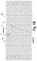
- FIG. 1Ais a plan view of a first embodiment of a stent in accordance with the present invention, the stent being shown in an unexpanded state;
- FIG. 1Bis a plan view of the first embodiment of a stent in accordance with the present invention, the stent being shown in a radially expanded state;
- FIG. 2is a plan view of a second embodiment of a stent in accordance with the present invention.
- FIG. 3is a plan view of a third embodiment of a stent in accordance with the present invention.
- FIG. 4is a plan view of a fourth embodiment of a stent in accordance with the present invention.
- FIG. 5is a sectional end view of a fifth embodiment of a stent in accordance with the present invention.
- FIG. 6is a lengthwise side outline view of the same embodiment as FIG. 5 ;
- FIG. 7Ais a plan view of another embodiment of a stent in accordance with the present invention.
- FIG. 7Bis a plan view of another embodiment of the stent in accordance with the present invention.
- FIG. 8is a sectional end view of another embodiment of the stent in accordance with the present invention.
- FIG. 9is a lengthwise side outline view of the embodiment shown in FIG. 8 ;
- FIG. 10Ais a sectional end view of an alternate embodiment of a stent in accordance with the present invention including graft material covering an outer surface of the stent;
- FIG. 10Bis a sectional end view of an alternate embodiment of a stent in accordance with the present invention including graft material covering an inner surface of the stent;
- FIG. 10Cis a sectional end view of an alternate embodiment of a stent in accordance with the present invention including graft material covering an outer surface and an inner surface of the stent;
- FIG. 11Ais a side view of an alternate embodiment of a stent in accordance with the present invention including graft material attached to the strut portion, the graft material covering the strut portion and the helical portion;
- FIG. 11Bis a side view of an alternate embodiment of a stent in accordance with the present invention including a plurality of sections of biocompatible graft material wherein a gap is provided between each of the sections of graft material;
- FIG. 11Cis a side view of an alternate embodiment of a stent in accordance with the present invention including a plurality of sections of a biocompatible graft material wherein the graft material of adjacent sections is overlapped;
- FIG. 11Dis a side view of an alternate embodiment of a stent in accordance with the present invention including a biocompatible graft material, the graft material having a bulge at the helical portions;
- FIG. 11Eis a side view of an alternate embodiment of a stent in accordance with the present invention including a biocompatible graft material, the graft material having a plurality of longitudinal openings over the helical portions;
- FIG. 11Fis a side view of an alternate embodiment of a stent in accordance with the present invention the graft material having a bulge at the helical portions and the graft material having a plurality of longitudinal openings over the helical portions;
- FIG. 11Gis a side view of an alternate embodiment of a stent in accordance with the present invention including a biocompatible graft material having a plurality of helical openings corresponding to a pitch of the helical elements;
- FIG. 11His a side view of an alternate embodiment of a stent in accordance with the present invention including a plurality of sections of biocompatible graft material each of the sections being attached to either the strut portion or the helical portion wherein a gap is provided between each of the sections of graft material;
- FIG. 11Jis a side view of an alternate embodiment of a stent in accordance with the present invention including a plurality of sections of biocompatible graft material, each of the sections being attached to either the strut portion or the helical portion wherein adjacent sections of graft material is overlapped;
- FIG. 12Ais a plan view of an alternate embodiment of a stent in an expanded state
- FIG. 12Bis a plan view of the stent of FIG. 12A in a crimped state such that the gap between helical elements is the same throughout the helical portions. Additionally, the length of the stent is the same in both the crimped and expanded state;
- FIG. 12Cis a plan view of the stent of FIG. 12A in a crimped state such that the gap between helical elements changes throughout the helical portion. Additionally, the stent is longer in the crimped state than the expanded state;
- FIG. 13is a plan view of an alternate embodiment of a stent in accordance with the present invention.
- Stent 10is made from a common material for self expanding stents, such as Nitinol nickel-titanium alloy (Ni/Ti), as is well known in the art.
- Ni/TiNitinol nickel-titanium alloy
- the stentis laser cut from tubing, for example, with a diameter of about 5 mm ( FIG. 1A ). It is then expanded and set to a diameter of about 8 mm ( FIG. 1B ), and for pre-deployment it would be crimped to a diameter appropriate for the application, for example about 3 mm.
- the present inventionis applicable to any type and size of stent.
- Stent 10is generally made up of strut portion 12 and helical portion 14 with axially aligned strut portion 12 alternating with helical portion 14 .
- strut portion 12is positioned at either end of stent 10 .
- Strut portion 12being radially expandable upon deployment.
- Each strut portion 12includes strut ring 16 having a pattern of wave-like strut elements 16 a that progresses circumferentially about the stent.
- Each strut element 16 ahas a width equal to the peak to peak distance around the stent and a length equal to the peak-to-peak distance along the length of the stent. It will be appreciated that strut ring 16 could be partially straightened (stretched vertically in FIG.
- the material of which stent 10 is madeis such that strut element 16 a will retain some wave-like shape in a radially expanded state.
- the stentwould be crimped and fitted into a catheter, and it would expand after the catheter is inserted into the vessel and the stent is advanced out of the catheter.
- Each helical portionis made up of a plurality of side-by-side helical elements 18 , each of which is helically wound about an axis of stent 10 .
- Helical portion 14is expandable radially upon deployment and compressible, expandable and bendable in a deployed state.
- Helical elements 18can be connected between opposed individual wave portions of strut element 16 a of different strut portions 12 .
- each helical element 18makes a complete rotation about the surface of stent 10 . However, they can make a partial rotation or more than one rotation.
- the helical portionis preferably constructed to permit repeated axial compression or expansion of about 20% (preferably between 15% and 25%) and simultaneously permit bending with a minimum bending radius of about 13 nm (preferably between 10 mm and 16 mm), all without failure.
- helical element 18is wound at least 90 degrees between strut elements 16 a connected to helical elements 18 .
- helical element 18is wound at least 360 degrees between strut elements 16 a connected to helical elements 18 .
- FIG. 2is a plan view of a second embodiment of stent 20 similar to stent 10 of FIG. 1 .
- the primary differencesare in the structure of strut portions 12 ′ and that there are right-handed and left-handed helical portions ( 14 R and 14 L, respectively).
- Each strut portion 12 ′comprises two adjacent strut rings 26 , 27 connected by short link 28 .
- the closely opposed peaks of strut elements 26 a , 27 aare connected by short link 28 , so that each strut portion 12 ′ has a double strut ring structure.
- twin or multiple strut ring strut portionsis that they offer increased radial stiffness over the single strut ring strut portion and can stabilize the strut portions so they are less affected by axial forces.
- a right-handed helical portion 14 Rthe elements 18 progress clockwise about the surface of stent 10 and, in a left-handed helical portion 14 L, they progress counterclockwise.
- Helical elements 18essentially float and permit relatively large displacements about and along the stent axis between the two strut ring portions at either end.
- the diameter of the stent at each helical portion 14 R, 14 Lis the same as the diameter of the stent at the strut portions 12 on either side. However, this need not be the case, as will become evident from additional embodiments discussed below.
- a benefit of using left-handed and right-handed helical portionsis that when the stent deploys the two portions rotate in opposite directions, maintaining the relative rotational positions of different axial portions of the stent.
- FIG. 3is another embodiment of stent 30 in accordance with the present invention. It is similar to stent 20 of FIG. 2 , except that helical portions 34 include helical element 38 which progresses bi-directionally (first counterclockwise and then clockwise) about the perimeter of stent 30 between connection locations on two different strut portions 12 ′. Helical element 38 is wound at least 90 degrees from a first strut portion 12 ′ to peak 35 and is wound 90 degrees from peak 35 to a second strut portion 12 ′ in order to maintain flexibility.
- the one-directional helical elements 18 of FIGS. 1A and 1Bcan allow adjacent strut portions to rotate relative to one another.
- the bi-directional helical elements 38limit the amount adjacent strut portions can rotate about the stent axis relative to one another but still provide axial and bending flexibility.
- FIG. 4is a plan view of a fourth embodiment of a stent in accordance with the present invention.
- stent 40has strut portions 12 ′ of FIG. 2 and the helical portions 14 L, 14 R ( FIG. 2 ) and helical portions 34 ( FIG. 3 ).
- the advantage of this constructionis that combining different types of helical elements allows a mix of properties as described herein, providing the opportunity for further optimization of overall stent performance for a given application.
- FIG. 5is a sectional view perpendicular to the axis of a fifth embodiment of stent 30 ′ in accordance with the present invention
- FIG. 6is a side outline view of the same embodiment.
- the stenthas the structure shown in FIG. 3 , except that helical portions 38 ′ have a larger diameter than strut portions 12 ′. In this construction the radial stiffness of the helical portions is increased, but to a lesser degree than the strut portions.
- the helical portionsmay not have as much outward force on a vessel as the strut portions when the strut is expanded.
- the geometry of FIG. 6will tend to force the helical portions to expand more than the strut portions, increasing the outward force of the helical portions, which equalizes the radial stiffness.
- Nitinol structureshave a biased stiffness, such that the force required to collapse the structure back towards the collapsed state is generally greater than the force that continues to dilate the diseased vessel when the stent is in its expanded state.
- a balloonis used to assist the expansion/dilation of the vessel.
- the biased stiffnessis enough to support the open vessel, but the outward force may not be enough to open the vessel (or it may take a longer period of time).
- a stent with the type of geometry shown in FIG. 5would therefore be a good expedient to use in conjunction with balloon assisted expansion, or other applications requiring additional expansive force.
- FIG. 7Ais a plan view of another embodiment of stent 40 B′ in accordance with the present invention.
- Stent 40 B′includes strut member 42 .
- Strut member 42progresses helically from one end of stent 40 B′ to the other.
- Strut member 42forms main body of stent 40 B′.
- each strut element 44 ais connected to a strut in a subsequent winding of strut member 42 by helical element 46 .
- helical element 46 of helical portion 45progresses helically less than one full rotation of 360 degrees about stent 40 B′.
- Helical element 46progresses in a direction opposite of the direction of which strut member 42 progresses helically about stent 40 B′.
- helical elements 46are axially abutted, forming a type of spring which permits a great deal of flexibility and axial expansion, while strut member 42 provides radial strength and retains the stent in its expanded condition.
- FIG. 7Bis a plan view of another embodiment of stent 40 C′ in accordance with the present invention.
- Stent 40 C′is similar to stent 40 W and includes strut member 42 .
- Strut member 42progresses helically from one end of stent 40 C′ to the other.
- Strut member 42forms main body of stent 40 C′.
- each strut element 44 ais connected to a strut in a subsequent winding of strut member 42 by helical element 47 .
- helical element 47progresses helically about stent 40 C′ in the same direction as strut member 42 progresses helically about stent 40 C′.
- Stent 40 C′includes transitional helical portions 49 and strut portions 48 at either end of stent 40 C′ to allow strut portion 48 to be provided at either end of stent 40 C′.
- Strut portion 48is wound about an axis of stent 40 C′.
- Strut portion 48has acute angle A 2 formed between a plan perpendicular to the axis of stent 40 C′ and a winding of strut portion 48 that is smaller than acute angle A 1 formed between the plane perpendicular to the axis of stent 40 C′ and the winding of strut member 42 .
- Transitional helical portion 49interconnects about one rotational winding or less of strut portion 48 .
- Strut portion 48is wound about an axis of stent 40 C′ having a number of windings less than about of the total number of windings of strut member 42 .
- the number of helical elements strut elements 50 in one rotation of a winding of strut portion 48is greater than the number of strut elements 44 a in one rotation of strut member 42 .
- Stents 40 B′ and 40 C′′have the advantage that the flexible helical elements are distributed more continuously along the length of the stent and may provide more continuous flexibility.
- stent 40 B′ or 40 C′are possible, depending upon the requirements of a particular design. For example, it might be desirable to connect fewer than all of strut elements 44 a in a particular winding to a subsequent winding, reducing the number of helical elements 46 . Helical elements 46 can extend for less or for any integer or non-integer multiple of a rotation.
- a stentcould also be made of a plurality of tubular sections each having the construction of stent 40 B′ or 40 C′ and joined lengthwise by another type of section.
- FIG. 8is a sectional view perpendicular to the axis of an embodiment of stent 20 ′ in accordance with the present invention
- FIG. 9is a side outline view of the same embodiment.
- the stenthas the structure shown in FIG. 1A , except that helical portions 14 ′ neck down to a smaller diameter than strut portions 12 ′. In this construction the helical portions will exert less force on the vessel wall than if the helical portions were the same diameter. Reducing the force the stent exerts on a vessel wall can reduce the amount of damage done to a vessel and provide a better performing stent.
- FIGS. 10A-10Care sectional views perpendicular to the axis of the stent in accordance with the present invention.
- Stent graft 60 , 70 and 80have a stent structure of the present invention of any of the embodiments described above with helical portions interposed between strut portions.
- biocompatible graft material 62covers outside 64 of stent graft 60 , as shown in FIG. 10A .
- biocompatible graft material 62covers inside 74 of stent 70 , as shown in FIG. 10B .
- graft material 62covers outside 64 and inside 74 of stent 80 , as shown in FIG. 10C .
- Graft material 62can be formed of any number of polymers or other biocompatible materials that have been woven or formed into a sheet or knitted surface. Alternatively, the stent can be coated with a polymer and/or drug eluting material as are known in the art.
- FIGS. 11A-11Jare side profile views of stent grafts including the features of the flexible stent structure of the present invention.
- Stent graft 100comprises a continuous covering of graft material 102 covering stent 10 , as shown in FIG. 11A .
- Graft material 102is attached to strut portions 12 .
- Graft material 102covers and is not attached to helical portions 14 .
- Stent graft 110comprises a plurality of sections 111 of graft material 112 covering the stent structure, as shown in FIG. 1B .
- Graft material 112is attached to strut portions 12 .
- Graft material 112covers at least a portion of helical portions 14 and is not attached to helical portions 14 .
- Gap 115is positioned between adjacent sections 111 of graft material 112 . Gap 115 will typically range in size between 0 (meaning no gap) and about 20% of the length of helical portion 14 .
- Stent graft 130comprises a continuous covering of graft material 132 , as shown in FIG. 11D .
- Graft material 132is attached to strut portions 12 .
- Graft material 132covers and is not attached to helical portions 14 .
- Graft material 132has bulge 133 at helical portions 14 .
- Stent graft 140comprises a continuous covering of graft material 142 , as shown in FIG. 11E .
- Graft material 142has a plurality of longitudinal openings 144 over helical portions 14 .
- Stent graft 150comprises a continuous covering of graft material 152 , as shown in FIG. 11F .
- Graft material 152has bulge 153 at helical portions 14 and has a plurality of longitudinal openings 154 over helical portions 14 .
- Stent graft 160comprises a continuous covering of graft material 162 , as shown in FIG. 11F .
- Graft material 162has helical openings 164 in helical portions 14 that correspond to the pitch and angle of helical portions 14 .
- Stent graft 170comprises a plurality of sections 171 of graft material 172 covering stent 10 , as shown in FIG. 11H .
- Sections 171can be attached to strut portions 12 or helical portions 14 .
- Gap 175is positioned between adjacent sections 171 of graft material 172 .
- Gap 175will typically range in size between 0 (meaning no gap) and about 20% of the length of helical portion 14 .
- Stent graft 180comprises a plurality of sections 181 of graft material 182 covering stent 10 , as shown in FIG. 11J .
- Sections 181can be attached to strut portions 12 or helical portions 14 .
- Sections 181 of graft material 182are positioned such that there is an overlap 185 between adjacent sections 181 of graft material 182 .
- Overlap 185will typically range in size between 0 (meaning no gap) and about 40% of the length of helical portion 14 .
- FIGS. 12A , 12 B and 12 Care plan views of stent 200 in accordance with the present invention.
- FIG. 12Ashows stent 200 in an expanded state with gap 202 between helical elements 18 .
- FIGS. 12B and 12Cshow stent 200 in two different compressed states.
- stent 200is compressed such that gap 212 between side-by-side helical elements 18 is about the same throughout helical portion 14 .
- the size of gap 212 between side-by-side helical elements 18can range between 0 and about the size of the gap 202 in the expanded state, for example, as shown in FIG. 12A . In other words, when the size of the gap is 0, there is no space between side-by-side helical elements 18 and side-by-side helical elements 18 contact one another.
- the helical elements of the stent shown in FIG. 12Bhave been wrapped around the stent a number of times such that in the crimped state the overall length 211 of the stent in the crimped state is the same as the overall length 201 of the stent in the expanded state shown in FIG. 12A , thereby eliminating foreshortening.
- stent 200is compressed such that helical element 18 is elongated and gap 222 between side-by-side helical elements 18 varies throughout the axial length of helical portion 14 .
- the size of gap 222 between adjacent helical elements 18can range between 0 and about the size of the gap 202 in the expanded state, for example, as shown in FIG. 12A .
- Helical elements 18are elongated elements without overlapping in the radial direction. In the deployed state, helical elements 18 are substantially parallel.
- Strut member 12 and helical elements 18define a cylinder having a constant diameter.
- the overall length 221 of the stent in the crimped stateis greater then the overall length 201 of the stent in the expanded state.
- helical elements 18are elongated elements separated in both the compressed and deployed state.
- Stent 200 in the compressed stateis longer than in the deployed state, as shown in FIG. 12A .
- the distance in the compressed stateis in the range of between zero and the distance between adjacent helical elements 18 in the deployed state.
- An additional methodcan be provided to crimp the stent such that the length of helical portions is shorter in the crimped state than in the expanded state. For example, if the stent of FIG. 12A were crimped similar to that shown in FIG. 12B , except no gap exists between side-by-side helical elements the stent would be have length 211 in the crimped state which is shorter than length 201 in the expanded state.
- a method of crimpingprovides a stent where the overall length is the same in the crimped and expanded state and there is no gap between helical elements in the crimped state.
- one preferred embodiment of the stentis to permit repeated axial compression or expansion of about 20% and simultaneously permit bending with a minimum bending radius of about 13 mm.
- One method to construct a stent of the present invention with a specific target for flexibilityis to vary the ratio between the sum of the gap space in the helical portion to the overall length. By increasing that ratio, the flexibility of the stent increases. This ratio will also be approximately the maximum axial compression the stent will allow. It will be appreciated that the maximum axial compression for safety may be limited by other factors such as strain in the helical elements.
- FIG. 13is a plan view of a stent 300 in accordance with the present invention.
- Stent 300is similar to other embodiments described above except it includes various configurations and various axial lengths of strut portions and various configurations and various axial lengths of helical portions.
- Strut portions 302 positioned at the outer most portion of stent 300includes long strut elements 301 .
- Long strut elements 301have length 311 .
- Length 311 of long strut element 301is greater than length 312 of strut portions 304 positioned at the inner portion of stent 300 .
- Long strut elements 301 provided on the ends of the stentmay be advantageous to provide better anchoring and provide an area for adjacent stents to overlap, but not impede the flexibility of the helical portion.
- the length of diseased arterymay be long, often longer than 10 cm. Multiple stents may be required to treat these long sections of diseased arteries.
- a common procedure in this caseis to overlap the adjacent stents so that the vessel being treated is covered.
- An advantage of the present inventionis that the elements that allow bending and axial flexibility (helical portion) are different than the elements that provide radial structure (strut portion) so that the strut portions on adjacent stents may overlap and not impede the movement of the helical portion and therefore the overall flexibility of the stent.
- Helical portion 303 that is adjacent to the strut portion 302comprises helical elements 18 that are connected to every strut element 301 of strut portion 302 .
- Helical portion 303can provide a high percentage of surface area for optimized delivery of a drug or other therapeutic agent.
- Strut portion 304is connected to helical portion 303 by helical element 18 at every strut element 16 a on side 320 of strut portion 304 and is connected to helical portion 309 at every other strut element 16 a on side 321 of strut portion 304 .
- Helical portion 309provides a lower percentage of surface area and greater flexibility than helical portion 303 . This type of configuration can provide a transition from a stiffer helical portion that has a high percentage of surface area to a more flexible helical portion.
- Helical portion 309has a higher ratio of the sum of gap lengths 323 to length 324 of helical portion 309 than the sum of gap lengths 325 to length 326 of helical portion 303 , so that helical portion 309 will generally have greater flexibility.
- Strut portion 306has half as many strut elements 305 as strut portions 302 or 304 and therefore generally has more open area compared to strut portion 302 or strut portion 304 .
- An advantage of a stent including a portion having a larger open area than other portions of the stentis that the larger open portion of the stent can be placed over an arterial bifurcation and not impede blood flow. Whereas the strut portion with a higher strut element density may impede blood flow.
- the stent structure of the present inventionnamely flexible helical portions flanked on either side by strut portions, provide an optimized structure where the strut portions stabilize a naturally unstable helical structure, and the helical portions provide net flexibility. There is substantial design optimization potential in combining various embodiments of the two portions.
- the flexible stents and stent grafts of the present inventionmay be placed within vessels using procedures well known in the art.
- the flexible stents and stent graftsmay be loaded into the proximal end of a catheter and advanced through the catheter and released at the desired site.
- the flexible stents and stent graftsmay be carried about the distal end of the catheter in a compressed state and released at the desired site.
- the flexible stents or stent graftsmay either be self-expanding or expanded by means such as an inflatable balloon segment of the catheter. After the stent(s) or stent graft(s) have been deposited at the desired intralumenal site, the catheter is withdrawn.
- the flexible stents and stent grafts of the present inventionmay be placed within body lumen such as vascular vessels or ducts of any mammal species including humans, without damaging the lumenal wall.
- the flexible stentcan be placed within a lesion or an aneurysm for treating the aneurysm.
- the flexible stentis placed in a super femoral artery upon insertion into the vessel, the flexible stent or stent grafts provides coverage of at least about 50% of the vessel.
- a stentcould be made with only right-handed or only left-handed helical portions, or the helical portions could have multiple reversals in winding direction rather than just one.
- the helical portionscould have any number of turns per unit length or a variable pitch, and the strut rings and/or helical portions could be of unequal length along the stent.
Landscapes
- Health & Medical Sciences (AREA)
- Engineering & Computer Science (AREA)
- Biomedical Technology (AREA)
- Heart & Thoracic Surgery (AREA)
- Life Sciences & Earth Sciences (AREA)
- Cardiology (AREA)
- Oral & Maxillofacial Surgery (AREA)
- Transplantation (AREA)
- Veterinary Medicine (AREA)
- Vascular Medicine (AREA)
- Public Health (AREA)
- Animal Behavior & Ethology (AREA)
- General Health & Medical Sciences (AREA)
- Optics & Photonics (AREA)
- Physics & Mathematics (AREA)
- Gastroenterology & Hepatology (AREA)
- Pulmonology (AREA)
- Prostheses (AREA)
- Media Introduction/Drainage Providing Device (AREA)
Abstract
Description
Claims (16)
Priority Applications (1)
| Application Number | Priority Date | Filing Date | Title |
|---|---|---|---|
| US11/749,306US7556644B2 (en) | 2005-04-04 | 2007-05-16 | Flexible stent |
Applications Claiming Priority (4)
| Application Number | Priority Date | Filing Date | Title |
|---|---|---|---|
| US66761305P | 2005-04-04 | 2005-04-04 | |
| US25022605A | 2005-10-14 | 2005-10-14 | |
| US11/397,987US7803180B2 (en) | 2005-04-04 | 2006-04-04 | Flexible stent |
| US11/749,306US7556644B2 (en) | 2005-04-04 | 2007-05-16 | Flexible stent |
Related Parent Applications (1)
| Application Number | Title | Priority Date | Filing Date |
|---|---|---|---|
| US11/397,987ContinuationUS7803180B2 (en) | 2005-04-04 | 2006-04-04 | Flexible stent |
Publications (2)
| Publication Number | Publication Date |
|---|---|
| US20070208416A1 US20070208416A1 (en) | 2007-09-06 |
| US7556644B2true US7556644B2 (en) | 2009-07-07 |
Family
ID=37074053
Family Applications (4)
| Application Number | Title | Priority Date | Filing Date |
|---|---|---|---|
| US11/397,987Active2029-02-07US7803180B2 (en) | 2005-04-04 | 2006-04-04 | Flexible stent |
| US11/749,306Expired - LifetimeUS7556644B2 (en) | 2005-04-04 | 2007-05-16 | Flexible stent |
| US12/884,514AbandonedUS20110029064A1 (en) | 2005-04-04 | 2010-09-17 | Flexible stent |
| US14/303,766Active2026-12-08US9592137B2 (en) | 2005-04-04 | 2014-06-13 | Flexible stent |
Family Applications Before (1)
| Application Number | Title | Priority Date | Filing Date |
|---|---|---|---|
| US11/397,987Active2029-02-07US7803180B2 (en) | 2005-04-04 | 2006-04-04 | Flexible stent |
Family Applications After (2)
| Application Number | Title | Priority Date | Filing Date |
|---|---|---|---|
| US12/884,514AbandonedUS20110029064A1 (en) | 2005-04-04 | 2010-09-17 | Flexible stent |
| US14/303,766Active2026-12-08US9592137B2 (en) | 2005-04-04 | 2014-06-13 | Flexible stent |
Country Status (9)
| Country | Link |
|---|---|
| US (4) | US7803180B2 (en) |
| EP (3) | EP2505166B1 (en) |
| JP (1) | JP5523700B2 (en) |
| CN (3) | CN102302390B (en) |
| AU (1) | AU2006231559B2 (en) |
| CA (1) | CA2610108C (en) |
| ES (1) | ES2764992T3 (en) |
| NZ (1) | NZ563119A (en) |
| WO (1) | WO2006108010A2 (en) |
Cited By (25)
| Publication number | Priority date | Publication date | Assignee | Title |
|---|---|---|---|---|
| US20100131048A1 (en)* | 2008-10-10 | 2010-05-27 | Reva Medical, Inc. | Expandable slide and lock stent |
| US7803180B2 (en) | 2005-04-04 | 2010-09-28 | Flexible Stenting Solutions, Inc. | Flexible stent |
| US20100286760A1 (en)* | 2009-04-24 | 2010-11-11 | Bradley Beach | Flexible devices |
| US20110093059A1 (en)* | 2009-10-20 | 2011-04-21 | Svelte Medical Systems, Inc. | Hybrid stent with helical connectors |
| US20120029622A1 (en)* | 2010-08-02 | 2012-02-02 | Baillargeon Brian P | Flexible helical stent having different helical regions |
| US8172894B2 (en) | 2007-01-26 | 2012-05-08 | Reva Medical, Inc. | Circumferentially nested expandable device |
| US20120245671A1 (en)* | 2011-03-25 | 2012-09-27 | Tyco Healthcare Group Lp | Vascular stent with improved vessel wall apposition |
| US8277500B2 (en) | 2004-12-17 | 2012-10-02 | Reva Medical, Inc. | Slide-and-lock stent |
| US8460363B2 (en) | 2007-11-30 | 2013-06-11 | Reva Medical, Inc. | Axially-radially nested expandable device |
| US8500794B2 (en) | 2007-08-02 | 2013-08-06 | Flexible Stenting Solutions, Inc. | Flexible stent |
| US8512394B2 (en) | 2004-07-21 | 2013-08-20 | Reva Medical Inc. | Balloon expandable crush-recoverable stent device |
| US8523936B2 (en) | 2010-04-10 | 2013-09-03 | Reva Medical, Inc. | Expandable slide and lock stent |
| US8617235B2 (en) | 2005-08-02 | 2013-12-31 | Reva Medical, Inc. | Axially nested slide and lock expandable device |
| US8864811B2 (en) | 2010-06-08 | 2014-10-21 | Veniti, Inc. | Bi-directional stent delivery system |
| US9149376B2 (en) | 2008-10-06 | 2015-10-06 | Cordis Corporation | Reconstrainable stent delivery system |
| US9149378B2 (en) | 2005-08-02 | 2015-10-06 | Reva Medical, Inc. | Axially nested slide and lock expandable device |
| US9233014B2 (en) | 2010-09-24 | 2016-01-12 | Veniti, Inc. | Stent with support braces |
| US9254205B2 (en) | 2012-09-27 | 2016-02-09 | Covidien Lp | Vascular stent with improved vessel wall apposition |
| US9301864B2 (en) | 2010-06-08 | 2016-04-05 | Veniti, Inc. | Bi-directional stent delivery system |
| US9408732B2 (en) | 2013-03-14 | 2016-08-09 | Reva Medical, Inc. | Reduced-profile slide and lock stent |
| US9566633B2 (en) | 2012-11-15 | 2017-02-14 | Vactronix Scientific, Inc. | Stents having a hybrid pattern and methods of manufacture |
| US9649211B2 (en) | 2009-11-04 | 2017-05-16 | Confluent Medical Technologies, Inc. | Alternating circumferential bridge stent design and methods for use thereof |
| US20170273810A1 (en)* | 2016-03-24 | 2017-09-28 | Covidien Lp | Vascular flow diversion |
| US10092427B2 (en) | 2009-11-04 | 2018-10-09 | Confluent Medical Technologies, Inc. | Alternating circumferential bridge stent design and methods for use thereof |
| US10117763B2 (en) | 2014-03-18 | 2018-11-06 | Boston Scientific Scimed, Inc. | Reduced granulation and inflammation stent design |
Families Citing this family (75)
| Publication number | Priority date | Publication date | Assignee | Title |
|---|---|---|---|---|
| US7887578B2 (en) | 1998-09-05 | 2011-02-15 | Abbott Laboratories Vascular Enterprises Limited | Stent having an expandable web structure |
| US6682554B2 (en) | 1998-09-05 | 2004-01-27 | Jomed Gmbh | Methods and apparatus for a stent having an expandable web structure |
| US6755856B2 (en) | 1998-09-05 | 2004-06-29 | Abbott Laboratories Vascular Enterprises Limited | Methods and apparatus for stenting comprising enhanced embolic protection, coupled with improved protection against restenosis and thrombus formation |
| US7815763B2 (en)* | 2001-09-28 | 2010-10-19 | Abbott Laboratories Vascular Enterprises Limited | Porous membranes for medical implants and methods of manufacture |
| US20040267349A1 (en) | 2003-06-27 | 2004-12-30 | Kobi Richter | Amorphous metal alloy medical devices |
| US8382821B2 (en) | 1998-12-03 | 2013-02-26 | Medinol Ltd. | Helical hybrid stent |
| EP1542616B1 (en) | 2002-09-20 | 2015-04-22 | Endologix, Inc. | Stent-graft with positioning anchor |
| US9039755B2 (en)* | 2003-06-27 | 2015-05-26 | Medinol Ltd. | Helical hybrid stent |
| US9155639B2 (en) | 2009-04-22 | 2015-10-13 | Medinol Ltd. | Helical hybrid stent |
| US8048145B2 (en) | 2004-07-22 | 2011-11-01 | Endologix, Inc. | Graft systems having filling structures supported by scaffolds and methods for their use |
| US8597716B2 (en)* | 2009-06-23 | 2013-12-03 | Abbott Cardiovascular Systems Inc. | Methods to increase fracture resistance of a drug-eluting medical device |
| US8961585B2 (en)* | 2005-04-25 | 2015-02-24 | Covidien Lp | Controlled fracture connections for stents |
| JP2009500121A (en) | 2005-07-07 | 2009-01-08 | ネリックス・インコーポレーテッド | System and method for treatment of an intraluminal aneurysm |
| US9017395B2 (en)* | 2007-03-09 | 2015-04-28 | Novostent Corporation | Vascular prosthesis and methods of use |
| US8002815B2 (en)* | 2007-03-09 | 2011-08-23 | Novostent Corporation | Delivery system and method for vascular prosthesis |
| US20080221658A1 (en)* | 2007-03-09 | 2008-09-11 | Novostent Corporation | Vascular prosthesis and methods of use |
| US8348994B2 (en)* | 2007-03-09 | 2013-01-08 | Novostent Corporation | Vascular prosthesis with alternating helical sections |
| US8016874B2 (en) | 2007-05-23 | 2011-09-13 | Abbott Laboratories Vascular Enterprises Limited | Flexible stent with elevated scaffolding properties |
| US8128679B2 (en) | 2007-05-23 | 2012-03-06 | Abbott Laboratories Vascular Enterprises Limited | Flexible stent with torque-absorbing connectors |
| US8920488B2 (en)* | 2007-12-20 | 2014-12-30 | Abbott Laboratories Vascular Enterprises Limited | Endoprosthesis having a stable architecture |
| US8337544B2 (en) | 2007-12-20 | 2012-12-25 | Abbott Laboratories Vascular Enterprises Limited | Endoprosthesis having flexible connectors |
| US7850726B2 (en) | 2007-12-20 | 2010-12-14 | Abbott Laboratories Vascular Enterprises Limited | Endoprosthesis having struts linked by foot extensions |
| EP2242454A1 (en)* | 2008-02-13 | 2010-10-27 | Nellix, Inc. | Graft endoframe having axially variable characteristics |
| EP2278939B1 (en) | 2008-04-25 | 2021-04-14 | Endologix LLC | Stent graft delivery system |
| US10716573B2 (en) | 2008-05-01 | 2020-07-21 | Aneuclose | Janjua aneurysm net with a resilient neck-bridging portion for occluding a cerebral aneurysm |
| US8974487B2 (en) | 2008-05-01 | 2015-03-10 | Aneuclose Llc | Aneurysm occlusion device |
| US10028747B2 (en) | 2008-05-01 | 2018-07-24 | Aneuclose Llc | Coils with a series of proximally-and-distally-connected loops for occluding a cerebral aneurysm |
| EP2299931B1 (en) | 2008-06-04 | 2020-01-08 | Endologix, Inc. | Sealing apparatus |
| CA2726452A1 (en)* | 2008-06-04 | 2009-12-30 | Nellix, Inc. | Docking apparatus and methods of use |
| US20150039072A1 (en)* | 2008-07-31 | 2015-02-05 | Bradley Beach | Flexible stent |
| CA2734493C (en)* | 2008-08-19 | 2016-09-27 | Tissuegen, Inc. | Self-expanding medical device |
| EP2352465B1 (en)* | 2008-08-27 | 2018-03-21 | Cook Medical Technologies LLC | Multi-section stent |
| US9149377B2 (en)* | 2008-10-10 | 2015-10-06 | Veryan Medical Ltd. | Stent suitable for deployment in a blood vessel |
| US20100137974A1 (en)* | 2008-12-02 | 2010-06-03 | Boston Scientific Scimed, Inc. | Stent with Graduated Stiffness |
| KR101810379B1 (en) | 2009-02-02 | 2017-12-20 | 코디스 코포레이션 | Flexible stent design |
| EP2429453B1 (en)* | 2009-05-14 | 2021-01-27 | Orbusneich Medical Pte. Ltd | Self-expanding stent with polygon transition zone |
| US9060889B2 (en)* | 2009-09-18 | 2015-06-23 | Medtronic Vascular, Inc. | Methods for forming an orthogonal end on a helical stent |
| US9358140B1 (en) | 2009-11-18 | 2016-06-07 | Aneuclose Llc | Stent with outer member to embolize an aneurysm |
| US8348987B2 (en)* | 2009-12-22 | 2013-01-08 | Cook Medical Technologies Llc | Balloon with scoring member |
| US20110276078A1 (en) | 2009-12-30 | 2011-11-10 | Nellix, Inc. | Filling structure for a graft system and methods of use |
| US8906057B2 (en) | 2010-01-04 | 2014-12-09 | Aneuclose Llc | Aneurysm embolization by rotational accumulation of mass |
| WO2011163236A2 (en) | 2010-06-21 | 2011-12-29 | Zorion Medical, Inc. | Bioabsorbable implants |
| US20120022578A1 (en)* | 2010-07-20 | 2012-01-26 | Cook Medical Technologies Llc | Frame-based vena cava filter |
| US8986369B2 (en) | 2010-12-01 | 2015-03-24 | Zorion Medical, Inc. | Magnesium-based absorbable implants |
| US8801768B2 (en) | 2011-01-21 | 2014-08-12 | Endologix, Inc. | Graft systems having semi-permeable filling structures and methods for their use |
| EP2693980B1 (en) | 2011-04-06 | 2022-07-13 | Endologix LLC | System for endovascular aneurysm treatment |
| US9138232B2 (en) | 2011-05-24 | 2015-09-22 | Aneuclose Llc | Aneurysm occlusion by rotational dispensation of mass |
| CN102335052A (en)* | 2011-07-15 | 2012-02-01 | 南京微创医学科技有限公司 | Anti-restenosis digestive tract stent |
| WO2013134560A1 (en)* | 2012-03-07 | 2013-09-12 | Orbusneich Medical, Inc. | Medical device for implantation into luminal structures |
| JP6220386B2 (en) | 2012-05-14 | 2017-10-25 | シー・アール・バード・インコーポレーテッドC R Bard Incorporated | Uniformly expandable stent |
| US20140114434A1 (en)* | 2012-10-22 | 2014-04-24 | Orbusneich Medical, Inc. | Medical device for implantation into luminal structures |
| USD723165S1 (en) | 2013-03-12 | 2015-02-24 | C. R. Bard, Inc. | Stent |
| BR112015022688B1 (en) | 2013-03-14 | 2020-10-06 | Endologix, Inc. | METHOD FOR FORMING A MATERIAL IN SITU THROUGH INCREASING THE VOLUME OF AN EXPANDABLE MEMBER OF A MEDICAL DEVICE |
| JP2016512751A (en) | 2013-03-14 | 2016-05-09 | パルマズ サイエンティフィック, インコーポレイテッドPalmaz Scientific, Inc. | Integrated medical device, method for manufacturing the same, and method for using the same |
| DE102013104062A1 (en) | 2013-04-22 | 2014-10-23 | Novatech Sa | stent |
| AU2014284216B2 (en) | 2013-06-21 | 2017-10-05 | Boston Scientific Scimed, Inc. | Stent with deflecting connector |
| JP5586742B1 (en)* | 2013-06-28 | 2014-09-10 | 株式会社World Medish | High flexibility stent |
| CN105705118B (en) | 2013-09-12 | 2018-03-30 | 波士顿科学国际有限公司 | Support with anti-displacement connector |
| US9980835B2 (en) | 2013-10-22 | 2018-05-29 | Orbusneich Medical Inc. | Medical device for implantation into luminal structures incorporating corrugated structural elements |
| JP5550028B1 (en)* | 2014-01-27 | 2014-07-16 | 株式会社World Medish | High flexibility stent |
| JP5695259B1 (en)* | 2014-02-19 | 2015-04-01 | 株式会社World Medish | High flexibility stent |
| USD888245S1 (en) | 2014-03-14 | 2020-06-23 | Vactronix Scientific, Llc | Stent device |
| WO2016054536A1 (en) | 2014-10-02 | 2016-04-07 | Boston Scientific Scimed, Inc. | Controlled ingrowth feature for antimigration |
| WO2016065086A1 (en) | 2014-10-22 | 2016-04-28 | Boston Scientific Scimed, Inc. | Stent with flexible hinge |
| WO2016073597A1 (en) | 2014-11-06 | 2016-05-12 | Boston Scientific Scimed, Inc. | Tracheal stent |
| US10299948B2 (en)* | 2014-11-26 | 2019-05-28 | W. L. Gore & Associates, Inc. | Balloon expandable endoprosthesis |
| CN104490500B (en)* | 2014-12-25 | 2017-01-18 | 周玉杰 | Chain type coronary stent suitable for coronary artery tortuosity angulation lesion |
| JP6734097B2 (en)* | 2015-03-31 | 2020-08-05 | 康宏 正林 | Highly flexible stent |
| US11628077B2 (en)* | 2016-10-31 | 2023-04-18 | Razmodics Llc | Post deployment radial force recovery of biodegradable scaffolds |
| US10342686B2 (en)* | 2017-08-10 | 2019-07-09 | Covidien Lp | Thin film mesh hybrid for treating vascular defects |
| CN109662820B (en)* | 2019-01-31 | 2023-06-16 | 深圳市科奕顿生物医疗科技有限公司 | A self-expanding stent and its preparation method and application |
| CN113413256B (en)* | 2019-01-31 | 2023-06-02 | 深圳市科奕顿生物医疗科技有限公司 | Self-expanding stent |
| WO2021146021A1 (en) | 2020-01-13 | 2021-07-22 | Boston Scientific Scimed, Inc. | Anti-migration stent |
| CN113017753A (en)* | 2021-02-26 | 2021-06-25 | 珠海通桥医疗科技有限公司 | Blood vessel support |
| US20250221834A1 (en)* | 2024-01-09 | 2025-07-10 | Route 92 Medical, Inc. | Systems and methods for treating vascular disease |
Citations (15)
| Publication number | Priority date | Publication date | Assignee | Title |
|---|---|---|---|---|
| US5449373A (en) | 1994-03-17 | 1995-09-12 | Medinol Ltd. | Articulated stent |
| US5545210A (en)* | 1994-09-22 | 1996-08-13 | Advanced Coronary Technology, Inc. | Method of implanting a permanent shape memory alloy stent |
| US5669932A (en)* | 1996-05-29 | 1997-09-23 | Isostent, Inc. | Means for accurately positioning an expandable stent |
| US5755781A (en)* | 1996-08-06 | 1998-05-26 | Iowa-India Investments Company Limited | Embodiments of multiple interconnected stents |
| US5810872A (en)* | 1997-03-14 | 1998-09-22 | Kanesaka; Nozomu | Flexible stent |
| US6042597A (en) | 1998-10-23 | 2000-03-28 | Scimed Life Systems, Inc. | Helical stent design |
| WO2000016718A1 (en) | 1998-09-21 | 2000-03-30 | Schmitz Rode Thomas | Tubular endoprosthesis |
| US6352552B1 (en)* | 2000-05-02 | 2002-03-05 | Scion Cardio-Vascular, Inc. | Stent |
| US20020082682A1 (en)* | 2000-12-19 | 2002-06-27 | Vascular Architects, Inc. | Biologically active agent delivery apparatus and method |
| US20030114920A1 (en)* | 1999-12-21 | 2003-06-19 | Caro Colin Gerald | Vascular stents |
| US20030195609A1 (en)* | 2002-04-10 | 2003-10-16 | Scimed Life Systems, Inc. | Hybrid stent |
| US6878162B2 (en)* | 2002-08-30 | 2005-04-12 | Edwards Lifesciences Ag | Helical stent having improved flexibility and expandability |
| US20060020322A1 (en)* | 2004-07-21 | 2006-01-26 | Alexander Leynov | Expandable framework with overlapping connectors |
| US7131993B2 (en)* | 2003-06-25 | 2006-11-07 | Boston Scientific Scimed, Inc. | Varying circumferential spanned connectors in a stent |
| US7169175B2 (en) | 2000-05-22 | 2007-01-30 | Orbusneich Medical, Inc. | Self-expanding stent |
Family Cites Families (250)
| Publication number | Priority date | Publication date | Assignee | Title |
|---|---|---|---|---|
| US4425908A (en) | 1981-10-22 | 1984-01-17 | Beth Israel Hospital | Blood clot filter |
| US4432132A (en)* | 1981-12-07 | 1984-02-21 | Bell Telephone Laboratories, Incorporated | Formation of sidewall oxide layers by reactive oxygen ion etching to define submicron features |
| US4665906A (en) | 1983-10-14 | 1987-05-19 | Raychem Corporation | Medical devices incorporating sim alloy elements |
| US5190546A (en) | 1983-10-14 | 1993-03-02 | Raychem Corporation | Medical devices incorporating SIM alloy elements |
| US5275622A (en) | 1983-12-09 | 1994-01-04 | Harrison Medical Technologies, Inc. | Endovascular grafting apparatus, system and method and devices for use therewith |
| US5102417A (en)* | 1985-11-07 | 1992-04-07 | Expandable Grafts Partnership | Expandable intraluminal graft, and method and apparatus for implanting an expandable intraluminal graft |
| US4813925A (en) | 1987-04-21 | 1989-03-21 | Medical Engineering Corporation | Spiral ureteral stent |
| US5133732A (en) | 1987-10-19 | 1992-07-28 | Medtronic, Inc. | Intravascular stent |
| US5266073A (en) | 1987-12-08 | 1993-11-30 | Wall W Henry | Angioplasty stent |
| IE73670B1 (en) | 1989-10-02 | 1997-07-02 | Medtronic Inc | Articulated stent |
| US5190540A (en) | 1990-06-08 | 1993-03-02 | Cardiovascular & Interventional Research Consultants, Inc. | Thermal balloon angioplasty |
| US5197978B1 (en) | 1991-04-26 | 1996-05-28 | Advanced Coronary Tech | Removable heat-recoverable tissue supporting device |
| FR2683449A1 (en)* | 1991-11-08 | 1993-05-14 | Cardon Alain | ENDOPROTHESIS FOR TRANSLUMINAL IMPLANTATION. |
| US5507767A (en) | 1992-01-15 | 1996-04-16 | Cook Incorporated | Spiral stent |
| US5683448A (en) | 1992-02-21 | 1997-11-04 | Boston Scientific Technology, Inc. | Intraluminal stent and graft |
| WO1995014500A1 (en) | 1992-05-01 | 1995-06-01 | Beth Israel Hospital | A stent |
| BR9405969A (en) | 1993-03-11 | 1996-02-06 | Medinol Ltd | Process of making a stent-type device from a wire stent-type device process to install a stent-type device and process of heating a nitinol-stent-type device |
| US5913897A (en) | 1993-09-16 | 1999-06-22 | Cordis Corporation | Endoprosthesis having multiple bridging junctions and procedure |
| GB2281865B (en) | 1993-09-16 | 1997-07-30 | Cordis Corp | Endoprosthesis having multiple laser welded junctions,method and procedure |
| US5989280A (en) | 1993-10-22 | 1999-11-23 | Scimed Lifesystems, Inc | Stent delivery apparatus and method |
| FR2714815B1 (en)* | 1994-01-10 | 1996-03-08 | Microfil Ind Sa | Elastic prosthesis to widen a duct, in particular a blood vessel. |
| US5733303A (en) | 1994-03-17 | 1998-03-31 | Medinol Ltd. | Flexible expandable stent |
| US5843120A (en) | 1994-03-17 | 1998-12-01 | Medinol Ltd. | Flexible-expandable stent |
| US6165210A (en) | 1994-04-01 | 2000-12-26 | Gore Enterprise Holdings, Inc. | Self-expandable helical intravascular stent and stent-graft |
| CA2157575C (en)* | 1994-04-01 | 2000-03-07 | Lilip Lau | Self-expandable stent and stent-graft and method of using them |
| ATE310839T1 (en)* | 1994-04-29 | 2005-12-15 | Scimed Life Systems Inc | STENT WITH COLLAGEN |
| US5824041A (en) | 1994-06-08 | 1998-10-20 | Medtronic, Inc. | Apparatus and methods for placement and repositioning of intraluminal prostheses |
| DE69528216T2 (en) | 1994-06-17 | 2003-04-17 | Terumo K.K., Tokio/Tokyo | Process for the production of a permanent stent |
| EP0794726A4 (en) | 1994-10-20 | 1998-01-07 | Instent Inc | Cystoscope delivery system |
| IL115756A0 (en)* | 1994-10-27 | 1996-01-19 | Medinol Ltd | Stent fabrication method |
| US5836964A (en) | 1996-10-30 | 1998-11-17 | Medinol Ltd. | Stent fabrication method |
| CA2301351C (en) | 1994-11-28 | 2002-01-22 | Advanced Cardiovascular Systems, Inc. | Method and apparatus for direct laser cutting of metal stents |
| US5591226A (en) | 1995-01-23 | 1997-01-07 | Schneider (Usa) Inc. | Percutaneous stent-graft and method for delivery thereof |
| DE69622231T2 (en) | 1995-03-01 | 2002-12-05 | Scimed Life Systems, Inc. | LENGTHFLEXIBLE AND EXPANDABLE STENT |
| US7204848B1 (en) | 1995-03-01 | 2007-04-17 | Boston Scientific Scimed, Inc. | Longitudinally flexible expandable stent |
| US6896696B2 (en) | 1998-11-20 | 2005-05-24 | Scimed Life Systems, Inc. | Flexible and expandable stent |
| US5591197A (en) | 1995-03-14 | 1997-01-07 | Advanced Cardiovascular Systems, Inc. | Expandable stent forming projecting barbs and method for deploying |
| DE69626108T2 (en) | 1995-04-14 | 2003-11-20 | Boston Scientific Ltd., St. Michael | STENTING DEVICE WITH ROLLING MEMBRANE |
| FI974063L (en)* | 1995-04-26 | 1997-12-19 | Medinol Ltd | Articulated expander |
| CN1140227C (en)* | 1995-04-26 | 2004-03-03 | 梅迪诺尔有限公司 | Articulated stent |
| US6602281B1 (en) | 1995-06-05 | 2003-08-05 | Avantec Vascular Corporation | Radially expansible vessel scaffold having beams and expansion joints |
| US5788707A (en) | 1995-06-07 | 1998-08-04 | Scimed Life Systems, Inc. | Pull back sleeve system with compression resistant inner shaft |
| US5776161A (en) | 1995-10-16 | 1998-07-07 | Instent, Inc. | Medical stents, apparatus and method for making same |
| AU7458596A (en) | 1995-10-20 | 1997-05-07 | Bandula Wijay | Vascular stent |
| US5913896A (en) | 1995-11-28 | 1999-06-22 | Medtronic, Inc. | Interwoven dual sinusoidal helix stent |
| AR005140A1 (en) | 1995-12-21 | 1999-04-14 | Cornell Res Foundation Inc | AN ISOLATED DNA MOLECULE THAT CODES A PROTEIN OR POLYPEPTIDE OF A VINE LEAF WINDING VIRUS, AN EXPRESSION SYSTEM, A GUEST CELL OR A TRANSGENIC RHYDOMA, INCLUDING SUCH MOLECULA DNA FROM MOLECULA TRANSPLANT, A METHOD FOR |
| EP1011889B1 (en) | 1996-01-30 | 2002-10-30 | Medtronic, Inc. | Articles for and methods of making stents |
| EP1066804B1 (en) | 1996-03-05 | 2004-07-14 | Evysio Medical Devices Ulc | Expandable stent |
| DE69725120T2 (en) | 1996-03-07 | 2004-07-08 | Med Institute, Inc., West Lafayette | SPREADABLE STENT |
| US6334871B1 (en) | 1996-03-13 | 2002-01-01 | Medtronic, Inc. | Radiopaque stent markers |
| IL117472A0 (en) | 1996-03-13 | 1996-07-23 | Instent Israel Ltd | Radiopaque stent markers |
| US5649949A (en) | 1996-03-14 | 1997-07-22 | Target Therapeutics, Inc. | Variable cross-section conical vasoocclusive coils |
| US5833699A (en) | 1996-04-10 | 1998-11-10 | Chuter; Timothy A. M. | Extending ribbon stent |
| FR2747301B1 (en) | 1996-04-10 | 1998-09-18 | Nycomed Lab Sa | IMPLANTABLE DEVICE FOR MAINTAINING OR RE-ESTABLISHING THE NORMAL PASSAGE SECTION OF A BODY DUCT, AS WELL AS A SYSTEM FOR ITS PLACEMENT |
| US6039756A (en) | 1996-04-26 | 2000-03-21 | Jang; G. David | Intravascular stent |
| US5954743A (en) | 1996-04-26 | 1999-09-21 | Jang; G. David | Intravascular stent |
| US5697971A (en) | 1996-06-11 | 1997-12-16 | Fischell; Robert E. | Multi-cell stent with cells having differing characteristics |
| DE19633901A1 (en)* | 1996-08-22 | 1998-02-26 | Thomas Prof Dr Med Ischinger | Vascular support in the form of a tube section-like support structure |
| US5807404A (en) | 1996-09-19 | 1998-09-15 | Medinol Ltd. | Stent with variable features to optimize support and method of making such stent |
| US6325826B1 (en) | 1998-01-14 | 2001-12-04 | Advanced Stent Technologies, Inc. | Extendible stent apparatus |
| US5776142A (en) | 1996-12-19 | 1998-07-07 | Medtronic, Inc. | Controllable stent delivery system and method |
| US6551350B1 (en) | 1996-12-23 | 2003-04-22 | Gore Enterprise Holdings, Inc. | Kink resistant bifurcated prosthesis |
| US5906759A (en)* | 1996-12-26 | 1999-05-25 | Medinol Ltd. | Stent forming apparatus with stent deforming blades |
| FR2758253B1 (en) | 1997-01-10 | 1999-04-02 | Nycomed Lab Sa | IMPLANTABLE DEVICE FOR THE TREATMENT OF A BODY DUCT |
| US5925061A (en) | 1997-01-13 | 1999-07-20 | Gore Enterprise Holdings, Inc. | Low profile vascular stent |
| US6241757B1 (en) | 1997-02-04 | 2001-06-05 | Solco Surgical Instrument Co., Ltd. | Stent for expanding body's lumen |
| US5827321A (en) | 1997-02-07 | 1998-10-27 | Cornerstone Devices, Inc. | Non-Foreshortening intraluminal prosthesis |
| ES2297092T3 (en) | 1997-02-11 | 2008-05-01 | Warsaw Orthopedic, Inc. | PREVIOUS CERVICAL PLATE OF UNIQUE BLOCK. |
| FR2760351B1 (en) | 1997-03-04 | 1999-05-28 | Bernard Glatt | HELICAL STENT FORMING DEVICE AND MANUFACTURING METHOD THEREOF |
| US5911732A (en) | 1997-03-10 | 1999-06-15 | Johnson & Johnson Interventional Systems, Co. | Articulated expandable intraluminal stent |
| US5792144A (en) | 1997-03-31 | 1998-08-11 | Cathco, Inc. | Stent delivery catheter system |
| US5718713A (en) | 1997-04-10 | 1998-02-17 | Global Therapeutics, Inc. | Surgical stent having a streamlined contour |
| US6273913B1 (en)* | 1997-04-18 | 2001-08-14 | Cordis Corporation | Modified stent useful for delivery of drugs along stent strut |
| US6033433A (en)* | 1997-04-25 | 2000-03-07 | Scimed Life Systems, Inc. | Stent configurations including spirals |
| US5741327A (en) | 1997-05-06 | 1998-04-21 | Global Therapeutics, Inc. | Surgical stent featuring radiopaque markers |
| DE29708879U1 (en) | 1997-05-20 | 1997-07-31 | Jomed Implantate GmbH, 72414 Rangendingen | Coronary stent |
| US5891192A (en) | 1997-05-22 | 1999-04-06 | The Regents Of The University Of California | Ion-implanted protein-coated intralumenal implants |
| BE1011180A6 (en) | 1997-05-27 | 1999-06-01 | Medicorp R & D Benelux Sa | Luminal endoprosthesis AUTO EXPANDABLE. |
| US5913895A (en) | 1997-06-02 | 1999-06-22 | Isostent, Inc. | Intravascular stent with enhanced rigidity strut members |
| EP0884029B1 (en) | 1997-06-13 | 2004-12-22 | Gary J. Becker | Expandable intraluminal endoprosthesis |
| EP0890346A1 (en) | 1997-06-13 | 1999-01-13 | Gary J. Becker | Expandable intraluminal endoprosthesis |
| US5843175A (en) | 1997-06-13 | 1998-12-01 | Global Therapeutics, Inc. | Enhanced flexibility surgical stent |
| FR2764794B1 (en) | 1997-06-20 | 1999-11-12 | Nycomed Lab Sa | EXPANDED TUBULAR DEVICE WITH VARIABLE THICKNESS |
| IL121316A (en) | 1997-07-15 | 2001-07-24 | Litana Ltd | Implantable medical device of shape memory alloy |
| US6340367B1 (en) | 1997-08-01 | 2002-01-22 | Boston Scientific Scimed, Inc. | Radiopaque markers and methods of using the same |
| US5824059A (en)* | 1997-08-05 | 1998-10-20 | Wijay; Bandula | Flexible stent |
| JP4292710B2 (en)* | 1997-09-24 | 2009-07-08 | エム イー ディ インスチィチュート インク | Radially expandable stent |
| NO311781B1 (en) | 1997-11-13 | 2002-01-28 | Medinol Ltd | Metal multilayer stents |
| US6156062A (en) | 1997-12-03 | 2000-12-05 | Ave Connaught | Helically wrapped interlocking stent |
| US6022374A (en) | 1997-12-16 | 2000-02-08 | Cardiovasc, Inc. | Expandable stent having radiopaque marker and method |
| US6626939B1 (en) | 1997-12-18 | 2003-09-30 | Boston Scientific Scimed, Inc. | Stent-graft with bioabsorbable structural support |
| US6190406B1 (en) | 1998-01-09 | 2001-02-20 | Nitinal Development Corporation | Intravascular stent having tapered struts |
| US6719779B2 (en) | 2000-11-07 | 2004-04-13 | Innercool Therapies, Inc. | Circulation set for temperature-controlled catheter and method of using the same |
| US6533807B2 (en) | 1998-02-05 | 2003-03-18 | Medtronic, Inc. | Radially-expandable stent and delivery system |
| US6676696B1 (en) | 1998-02-12 | 2004-01-13 | Thomas R. Marotta | Endovascular prosthesis |
| EP1065993B1 (en) | 1998-03-05 | 2010-08-11 | Boston Scientific Limited | Intraluminal stent |
| US6019778A (en) | 1998-03-13 | 2000-02-01 | Cordis Corporation | Delivery apparatus for a self-expanding stent |
| US7179289B2 (en) | 1998-03-30 | 2007-02-20 | Conor Medsystems, Inc. | Expandable medical device for delivery of beneficial agent |
| US6241762B1 (en)* | 1998-03-30 | 2001-06-05 | Conor Medsystems, Inc. | Expandable medical device with ductile hinges |
| US6264687B1 (en) | 1998-04-20 | 2001-07-24 | Cordis Corporation | Multi-laminate stent having superelastic articulated sections |
| US6168621B1 (en) | 1998-05-29 | 2001-01-02 | Scimed Life Systems, Inc. | Balloon expandable stent with a self-expanding portion |
| US6740113B2 (en) | 1998-05-29 | 2004-05-25 | Scimed Life Systems, Inc. | Balloon expandable stent with a self-expanding portion |
| AU756080B2 (en) | 1998-06-04 | 2003-01-02 | New York University | Endovascular thin film devices and methods for treating and preventing stroke |
| US6261319B1 (en) | 1998-07-08 | 2001-07-17 | Scimed Life Systems, Inc. | Stent |
| US5911754A (en)* | 1998-07-24 | 1999-06-15 | Uni-Cath Inc. | Flexible stent with effective strut and connector patterns |
| DE19839646A1 (en) | 1998-08-31 | 2000-03-09 | Jomed Implantate Gmbh | Stent |
| US6093194A (en) | 1998-09-14 | 2000-07-25 | Endocare, Inc. | Insertion device for stents and methods for use |
| US6544278B1 (en) | 1998-11-06 | 2003-04-08 | Scimed Life Systems, Inc. | Rolling membrane stent delivery system |
| US6059813A (en) | 1998-11-06 | 2000-05-09 | Scimed Life Systems, Inc. | Rolling membrane stent delivery system |
| CA2289169A1 (en) | 1998-11-11 | 2000-05-11 | Ogawa Spring Co., Ltd. | Stent, manufacturing method thereof and indwelling method thereof |
| DE69937415T2 (en)* | 1998-11-20 | 2008-02-14 | Boston Scientific Ltd., St. Michael | Longitudinally flexible and expandable stent |
| US6503270B1 (en) | 1998-12-03 | 2003-01-07 | Medinol Ltd. | Serpentine coiled ladder stent |
| US6355059B1 (en) | 1998-12-03 | 2002-03-12 | Medinol, Ltd. | Serpentine coiled ladder stent |
| SG75982A1 (en) | 1998-12-03 | 2000-10-24 | Medinol Ltd | Controlled detachment stents |
| US6743252B1 (en) | 1998-12-18 | 2004-06-01 | Cook Incorporated | Cannula stent |
| US6254609B1 (en) | 1999-01-11 | 2001-07-03 | Scimed Life Systems, Inc. | Self-expanding stent delivery system with two sheaths |
| EP1020166A1 (en) | 1999-01-12 | 2000-07-19 | Orbus Medical Technologies, Inc. | Expandable intraluminal endoprosthesis |
| US6632236B2 (en)* | 1999-03-12 | 2003-10-14 | Arteria Medical Science, Inc. | Catheter having radially expandable main body |
| US6287333B1 (en) | 1999-03-15 | 2001-09-11 | Angiodynamics, Inc. | Flexible stent |
| US6899730B1 (en) | 1999-04-15 | 2005-05-31 | Scimed Life Systems, Inc. | Catheter-stent device |
| US6860899B1 (en) | 1999-04-15 | 2005-03-01 | Boston Scientific Scimed, Inc. | Method for treating neurovascular aneurysms |
| US6730116B1 (en) | 1999-04-16 | 2004-05-04 | Medtronic, Inc. | Medical device for intraluminal endovascular stenting |
| US6273911B1 (en) | 1999-04-22 | 2001-08-14 | Advanced Cardiovascular Systems, Inc. | Variable strength stent |
| US6245101B1 (en)* | 1999-05-03 | 2001-06-12 | William J. Drasler | Intravascular hinge stent |
| US6673103B1 (en) | 1999-05-20 | 2004-01-06 | Scimed Life Systems, Inc. | Mesh and stent for increased flexibility |
| US6551351B2 (en)* | 1999-07-02 | 2003-04-22 | Scimed Life Systems | Spiral wound stent |
| US6485507B1 (en) | 1999-07-28 | 2002-11-26 | Scimed Life Systems | Multi-property nitinol by heat treatment |
| US6142987A (en) | 1999-08-03 | 2000-11-07 | Scimed Life Systems, Inc. | Guided filter with support wire and methods of use |
| US6302907B1 (en) | 1999-10-05 | 2001-10-16 | Scimed Life Systems, Inc. | Flexible endoluminal stent and process of manufacture |
| AU1084101A (en) | 1999-10-14 | 2001-04-23 | United Stenting, Inc. | Stents with multilayered struts |
| US6171328B1 (en) | 1999-11-09 | 2001-01-09 | Embol-X, Inc. | Intravascular catheter filter with interlocking petal design and methods of use |
| US6264671B1 (en) | 1999-11-15 | 2001-07-24 | Advanced Cardiovascular Systems, Inc. | Stent delivery catheter and method of use |
| US6585758B1 (en) | 1999-11-16 | 2003-07-01 | Scimed Life Systems, Inc. | Multi-section filamentary endoluminal stent |
| CN1186423C (en) | 1999-12-03 | 2005-01-26 | 中国科学院南京土壤研究所 | Process for preparing ammonia suppressing film of rice field |
| US6334866B1 (en) | 2000-01-14 | 2002-01-01 | William H. Wall | Stent device for performing endovascular repair of aneurysms |
| US6723119B2 (en) | 2000-03-01 | 2004-04-20 | Medinol Ltd. | Longitudinally flexible stent |
| US7758627B2 (en) | 2000-03-01 | 2010-07-20 | Medinol, Ltd. | Longitudinally flexible stent |
| US7828835B2 (en) | 2000-03-01 | 2010-11-09 | Medinol Ltd. | Longitudinally flexible stent |
| SG86458A1 (en) | 2000-03-01 | 2002-02-19 | Medinol Ltd | Longitudinally flexible stent |
| US6953476B1 (en) | 2000-03-27 | 2005-10-11 | Neovasc Medical Ltd. | Device and method for treating ischemic heart disease |
| US8236048B2 (en) | 2000-05-12 | 2012-08-07 | Cordis Corporation | Drug/drug delivery systems for the prevention and treatment of vascular disease |
| US6423091B1 (en) | 2000-05-16 | 2002-07-23 | Cordis Corporation | Helical stent having flat ends |
| AU2001275100A1 (en) | 2000-05-31 | 2001-12-11 | Courtney, Brian K. | Embolization protection system for vascular procedures |
| US8298257B2 (en) | 2000-06-29 | 2012-10-30 | Concentric Medical, Inc. | Systems, methods and devices for removing obstructions from a blood vessel |
| US6540775B1 (en) | 2000-06-30 | 2003-04-01 | Cordis Corporation | Ultraflexible open cell stent |
| US6969401B1 (en) | 2000-08-18 | 2005-11-29 | Marotta Thomas R | Endovascular prosthesis |
| US6565595B1 (en) | 2000-09-18 | 2003-05-20 | Scimed Life Systems, Inc. | Two component sleeves |
| US6607552B1 (en) | 2000-09-18 | 2003-08-19 | Scimed Life Systems, Inc. | Rolling socks |
| US6805898B1 (en) | 2000-09-28 | 2004-10-19 | Advanced Cardiovascular Systems, Inc. | Surface features of an implantable medical device |
| US6492615B1 (en) | 2000-10-12 | 2002-12-10 | Scimed Life Systems, Inc. | Laser polishing of medical devices |
| US7163552B2 (en) | 2000-10-13 | 2007-01-16 | Medtronic Vascular, Inc. | Stent delivery system with hydraulic deployment |
| US6663664B1 (en) | 2000-10-26 | 2003-12-16 | Advanced Cardiovascular Systems, Inc. | Self-expanding stent with time variable radial force |
| US6506211B1 (en) | 2000-11-13 | 2003-01-14 | Scimed Life Systems, Inc. | Stent designs |
| US6843802B1 (en) | 2000-11-16 | 2005-01-18 | Cordis Corporation | Delivery apparatus for a self expanding retractable stent |
| US6579308B1 (en) | 2000-11-28 | 2003-06-17 | Scimed Life Systems, Inc. | Stent devices with detachable distal or proximal wires |
| US6517567B2 (en) | 2000-11-30 | 2003-02-11 | Albert R. Bass, Jr. | Apparatus and method for pacifier withdrawal |
| JP4323102B2 (en) | 2001-01-15 | 2009-09-02 | テルモ株式会社 | Flexible stent |
| WO2002054989A2 (en)* | 2001-01-15 | 2002-07-18 | Terumo Corp | Stent |
| JP4727070B2 (en) | 2001-06-01 | 2011-07-20 | テルモ株式会社 | Stent |
| US7169165B2 (en) | 2001-01-16 | 2007-01-30 | Boston Scientific Scimed, Inc. | Rapid exchange sheath for deployment of medical devices and methods of use |
| US6899727B2 (en) | 2001-01-22 | 2005-05-31 | Gore Enterprise Holdings, Inc. | Deployment system for intraluminal devices |
| US6736839B2 (en) | 2001-02-01 | 2004-05-18 | Charles Cummings | Medical device delivery system |
| US6563080B2 (en) | 2001-02-15 | 2003-05-13 | Scimed Life Systems, Inc. | Laser cutting of stents and other medical devices |
| US6679911B2 (en)* | 2001-03-01 | 2004-01-20 | Cordis Corporation | Flexible stent |
| US6613077B2 (en) | 2001-03-27 | 2003-09-02 | Scimed Life Systems, Inc. | Stent with controlled expansion |
| GB0107910D0 (en) | 2001-03-29 | 2001-05-23 | Isis Innovation | Deployable stent |
| EP1245203B1 (en) | 2001-03-30 | 2006-03-08 | Terumo Kabushiki Kaisha | Stent |
| DE60237813D1 (en) | 2001-05-11 | 2010-11-11 | Epion Corp | METHOD FOR IMPROVING THE EFFECTIVENESS OF MEDICAL DEVICES BY MOUNTING MEDICAMENTS ON THE SURFACE |
| US6599314B2 (en) | 2001-06-08 | 2003-07-29 | Cordis Corporation | Apparatus and method for stenting a vessel using balloon-actuated stent with interlocking elements |
| US6612012B2 (en) | 2001-06-11 | 2003-09-02 | Cordis Neurovascular, Inc. | Method of manufacturing small profile medical devices |
| US6673106B2 (en) | 2001-06-14 | 2004-01-06 | Cordis Neurovascular, Inc. | Intravascular stent device |
| US6818013B2 (en) | 2001-06-14 | 2004-11-16 | Cordis Corporation | Intravascular stent device |
| US6796999B2 (en) | 2001-09-06 | 2004-09-28 | Medinol Ltd. | Self articulating stent |
| JP2005501651A (en) | 2001-09-10 | 2005-01-20 | メディノール リミテッド | Longitudinal flexible stent [Related application] This application is a continuation-in-part of application No. 09 / 864,389, filed on May 25, 2001, and is filed on February 28, 2001. No. 09 / 795,794, a continuation-in-part application, which is an application of application No. 09 / 516,753 filed on Mar. 1, 2000. Claims priority of provisional application 60 / 202,723 of monthly application. |
| US20030229390A1 (en) | 2001-09-17 | 2003-12-11 | Control Delivery Systems, Inc. | On-stent delivery of pyrimidines and purine analogs |
| US7175655B1 (en) | 2001-09-17 | 2007-02-13 | Endovascular Technologies, Inc. | Avoiding stress-induced martensitic transformation in nickel titanium alloys used in medical devices |
| JP3605388B2 (en) | 2001-10-16 | 2004-12-22 | 川澄化学工業株式会社 | Stent |
| US20050070992A1 (en) | 2001-11-28 | 2005-03-31 | Aptus Endosystems, Inc. | Prosthesis systems and methods sized and configured for the receipt and retention of fasteners |
| JP4331610B2 (en) | 2001-12-20 | 2009-09-16 | トリバスキュラー2,インコーポレイティド | Advanced endovascular graft |
| US7163553B2 (en) | 2001-12-28 | 2007-01-16 | Advanced Cardiovascular Systems, Inc. | Intravascular stent and method of use |
| US6981985B2 (en) | 2002-01-22 | 2006-01-03 | Boston Scientific Scimed, Inc. | Stent bumper struts |
| US7354450B2 (en)* | 2002-01-30 | 2008-04-08 | Boston Scientific Scimed, Inc. | Stent with wishbone connectors and serpentine bands |
| US7445629B2 (en) | 2002-01-31 | 2008-11-04 | Boston Scientific Scimed, Inc. | Medical device for delivering biologically active material |
| US7169170B2 (en) | 2002-02-22 | 2007-01-30 | Cordis Corporation | Self-expanding stent delivery system |
| US7052511B2 (en) | 2002-04-04 | 2006-05-30 | Scimed Life Systems, Inc. | Delivery system and method for deployment of foreshortening endoluminal devices |
| US20030204244A1 (en) | 2002-04-26 | 2003-10-30 | Stiger Mark L. | Aneurysm exclusion stent |
| DE10219014A1 (en) | 2002-04-27 | 2003-11-13 | Ruesch Willy Gmbh | Self-expanding stent for reinforcing and/or keeping open a hollow organ comprise two elastic tubular layers which bracket and positionally fix at least one helical filament |
| US7122048B2 (en) | 2002-05-03 | 2006-10-17 | Scimed Life Systems, Inc. | Hypotube endoluminal device |
| US7128756B2 (en) | 2002-05-08 | 2006-10-31 | Abbott Laboratories | Endoprosthesis having foot extensions |
| WO2003096935A1 (en) | 2002-05-16 | 2003-11-27 | Cook Incorporated | Flexible barb for anchoring a prosthesis |
| CA2678623C (en) | 2002-05-17 | 2011-07-19 | The Viking Corporation | Fire protection system |
| US6830638B2 (en) | 2002-05-24 | 2004-12-14 | Advanced Cardiovascular Systems, Inc. | Medical devices configured from deep drawn nickel-titanium alloys and nickel-titanium clad alloys and method of making the same |
| US20040002752A1 (en) | 2002-06-26 | 2004-01-01 | Scimed Life Systems, Inc. | Sacrificial anode stent system |
| US8080052B2 (en) | 2002-06-28 | 2011-12-20 | Cordis Corporation | Stent with diagonal flexible connecting links |
| US6761731B2 (en) | 2002-06-28 | 2004-07-13 | Cordis Corporation | Balloon-stent interaction to help reduce foreshortening |
| US6969402B2 (en) | 2002-07-26 | 2005-11-29 | Syntheon, Llc | Helical stent having flexible transition zone |
| DE60201905T2 (en) | 2002-09-09 | 2005-11-10 | Abbott Laboratories Vascular Enterprises Ltd. | System for introducing a self-expanding stent |
| US8444666B2 (en) | 2002-09-12 | 2013-05-21 | Cook Medical Technologies Llc | Retrievable filter |
| US7001422B2 (en) | 2002-09-23 | 2006-02-21 | Cordis Neurovascular, Inc | Expandable stent and delivery system |
| US7135038B1 (en) | 2002-09-30 | 2006-11-14 | Advanced Cardiovascular Systems, Inc. | Drug eluting stent |
| US7169172B2 (en) | 2002-11-01 | 2007-01-30 | Counter Clockwise, Inc. | Method and apparatus for caged stent delivery |
| US7169178B1 (en) | 2002-11-12 | 2007-01-30 | Advanced Cardiovascular Systems, Inc. | Stent with drug coating |
| US6923829B2 (en) | 2002-11-25 | 2005-08-02 | Advanced Bio Prosthetic Surfaces, Ltd. | Implantable expandable medical devices having regions of differential mechanical properties and methods of making same |
| US7678068B2 (en) | 2002-12-02 | 2010-03-16 | Gi Dynamics, Inc. | Atraumatic delivery devices |
| US7044965B1 (en) | 2002-12-13 | 2006-05-16 | Spielberg Theodore E | Therapeutic cellular stent |
| AU2003301005A1 (en) | 2002-12-16 | 2004-07-22 | The Regents Of The University Of Michigan | Assembly and planar structure for use therein which is expandable into a 3-d structure such as a stent and device for making the planar structure |
| DE10261822A1 (en)* | 2002-12-20 | 2004-07-01 | Biotronik Meß- und Therapiegeräte GmbH & Co. Ingenieurbüro Berlin | Helix bridge connection |
| US20050033410A1 (en) | 2002-12-24 | 2005-02-10 | Novostent Corporation | Vascular prothesis having flexible configuration |
| US20050165469A1 (en)* | 2002-12-24 | 2005-07-28 | Michael Hogendijk | Vascular prosthesis including torsional stabilizer and methods of use |
| US7846198B2 (en)* | 2002-12-24 | 2010-12-07 | Novostent Corporation | Vascular prosthesis and methods of use |
| US20040147998A1 (en) | 2003-01-24 | 2004-07-29 | Nolting John E. | Differentially coated stent |
| US7179286B2 (en)* | 2003-02-21 | 2007-02-20 | Boston Scientific Scimed, Inc. | Stent with stepped connectors |
| US7942920B2 (en) | 2003-02-25 | 2011-05-17 | Cordis Corporation | Stent with nested fingers for enhanced vessel coverage |
| US8083791B2 (en) | 2003-04-14 | 2011-12-27 | Tryton Medical, Inc. | Method of treating a lumenal bifurcation |
| US7591832B2 (en) | 2003-04-24 | 2009-09-22 | Medtronic, Inc. | Expandable guide sheath and apparatus with distal protection and methods for use |
| KR100561713B1 (en) | 2003-05-23 | 2006-03-20 | (주) 태웅메디칼 | Method for manufacturing a variable state stent and a variable state stent produced thereby |
| US7112216B2 (en)* | 2003-05-28 | 2006-09-26 | Boston Scientific Scimed, Inc. | Stent with tapered flexibility |
| US20040260384A1 (en) | 2003-06-17 | 2004-12-23 | Medtronic Ave | Superelastic coiled stent |
| US20040260377A1 (en) | 2003-06-17 | 2004-12-23 | Medinol, Ltd. | Shape memory alloy endoprosthesis delivery system |
| US6945990B2 (en) | 2003-08-16 | 2005-09-20 | Medtronic Vascular, Inc. | Double sheath deployment system |
| US20050080479A1 (en) | 2003-09-29 | 2005-04-14 | Feng James Q. | Expandable endovascular stent |
| US7060090B2 (en) | 2003-10-15 | 2006-06-13 | Medtronic Vascular, Inc. | Stent with increased longitudinal flexibility and scaffolding |
| US20050090888A1 (en) | 2003-10-28 | 2005-04-28 | Hines Richard A. | Pleated stent assembly |
| US7316711B2 (en) | 2003-10-29 | 2008-01-08 | Medtronic Vascular, Inc. | Intralumenal stent device for use in body lumens of various diameters |
| US20050096725A1 (en) | 2003-10-29 | 2005-05-05 | Pomeranz Mark L. | Expandable stent having removable slat members |
| US20050125025A1 (en) | 2003-12-05 | 2005-06-09 | Marcel Rioux | Styptic device |
| US7873400B2 (en) | 2003-12-10 | 2011-01-18 | Stryker Leibinger Gmbh & Co. Kg. | Adapter for surgical navigation trackers |
| US20050131530A1 (en) | 2003-12-15 | 2005-06-16 | Darack Ed E. | Endoluminal stent |
| WO2005063251A1 (en) | 2003-12-17 | 2005-07-14 | Pfizer Products Inc. | Modified stent useful for delivery of drugs along stent strut |
| US7243408B2 (en) | 2004-02-09 | 2007-07-17 | Boston Scientific Scimed, Inc. | Process method for attaching radio opaque markers to shape memory stent |
| US7766960B2 (en)* | 2004-04-30 | 2010-08-03 | Novostent Corporation | Delivery catheter that controls foreshortening of ribbon-type prostheses and methods of making and use |
| US7763064B2 (en) | 2004-06-08 | 2010-07-27 | Medinol, Ltd. | Stent having struts with reverse direction curvature |
| JP2006029900A (en) | 2004-07-14 | 2006-02-02 | Tdk Corp | Magnetic sensor for encoder |
| US8308789B2 (en) | 2004-07-16 | 2012-11-13 | W. L. Gore & Associates, Inc. | Deployment system for intraluminal devices |
| US7323008B2 (en) | 2004-08-09 | 2008-01-29 | Medtronic Vascular, Inc. | Flexible stent |
| US20060060266A1 (en) | 2004-09-01 | 2006-03-23 | Pst, Llc | Stent and method for manufacturing the stent |
| US20060074480A1 (en) | 2004-09-01 | 2006-04-06 | Pst, Llc | Stent and method for manufacturing the stent |
| US7018403B1 (en) | 2004-09-14 | 2006-03-28 | Advanced Cardiovascular Systems, Inc. | Inclined stent pattern for vulnerable plaque |
| US7914570B2 (en) | 2004-10-07 | 2011-03-29 | Boston Scientific Scimed, Inc. | Non-shortening helical stent |
| MX2007005168A (en) | 2004-10-26 | 2007-10-10 | Johnson & Johnson | Stent having phased hoop sections. |
| US20060173490A1 (en) | 2005-02-01 | 2006-08-03 | Boston Scientific Scimed, Inc. | Filter system and method |
| US7918880B2 (en) | 2005-02-16 | 2011-04-05 | Boston Scientific Scimed, Inc. | Self-expanding stent and delivery system |
| EP1861133B1 (en) | 2005-02-28 | 2012-11-21 | Spirus Medical Inc. | Rotate-to-advance catheterization system |
| JP5523700B2 (en)* | 2005-04-04 | 2014-06-18 | フレキシブル ステンティング ソリューションズ,インク. | Flexible stent |
| US20070055365A1 (en) | 2005-04-28 | 2007-03-08 | The Cleveland Clinic Foundation | Stent with integrated filter |
| US20070027522A1 (en) | 2005-06-14 | 2007-02-01 | Chang Jean C | Stent delivery and guidewire systems |
| US7637939B2 (en) | 2005-06-30 | 2009-12-29 | Boston Scientific Scimed, Inc. | Hybrid stent |
| US8956400B2 (en) | 2005-10-14 | 2015-02-17 | Flexible Stenting Solutions, Inc. | Helical stent |
| US7988723B2 (en)* | 2007-08-02 | 2011-08-02 | Flexible Stenting Solutions, Inc. | Flexible stent |
| EP2421470A4 (en)* | 2009-04-24 | 2016-03-30 | Flexible Stenting Solutions Inc | Flexible devices |
- 2006
- 2006-04-04JPJP2008505478Apatent/JP5523700B2/enactiveActive
- 2006-04-04USUS11/397,987patent/US7803180B2/enactiveActive
- 2006-04-04CNCN201110281152.XApatent/CN102302390B/enactiveActive
- 2006-04-04ESES06740521Tpatent/ES2764992T3/enactiveActive
- 2006-04-04EPEP12171358.0Apatent/EP2505166B1/enactiveActive
- 2006-04-04CACA2610108Apatent/CA2610108C/enactiveActive
- 2006-04-04EPEP19202499.0Apatent/EP3613387B1/enactiveActive
- 2006-04-04AUAU2006231559Apatent/AU2006231559B2/enactiveActive
- 2006-04-04CNCN201110281185.4Apatent/CN102309370B/enactiveActive
- 2006-04-04WOPCT/US2006/012579patent/WO2006108010A2/enactiveApplication Filing
- 2006-04-04CNCN200680011292.2Apatent/CN101484089B/enactiveActive
- 2006-04-04EPEP06740521.7Apatent/EP1871292B1/enactiveActive
- 2006-04-04NZNZ563119Apatent/NZ563119A/enunknown
- 2007
- 2007-05-16USUS11/749,306patent/US7556644B2/ennot_activeExpired - Lifetime
- 2010
- 2010-09-17USUS12/884,514patent/US20110029064A1/ennot_activeAbandoned
- 2014
- 2014-06-13USUS14/303,766patent/US9592137B2/enactiveActive
Patent Citations (15)
| Publication number | Priority date | Publication date | Assignee | Title |
|---|---|---|---|---|
| US5449373A (en) | 1994-03-17 | 1995-09-12 | Medinol Ltd. | Articulated stent |
| US5545210A (en)* | 1994-09-22 | 1996-08-13 | Advanced Coronary Technology, Inc. | Method of implanting a permanent shape memory alloy stent |
| US5669932A (en)* | 1996-05-29 | 1997-09-23 | Isostent, Inc. | Means for accurately positioning an expandable stent |
| US5755781A (en)* | 1996-08-06 | 1998-05-26 | Iowa-India Investments Company Limited | Embodiments of multiple interconnected stents |
| US5810872A (en)* | 1997-03-14 | 1998-09-22 | Kanesaka; Nozomu | Flexible stent |
| WO2000016718A1 (en) | 1998-09-21 | 2000-03-30 | Schmitz Rode Thomas | Tubular endoprosthesis |
| US6042597A (en) | 1998-10-23 | 2000-03-28 | Scimed Life Systems, Inc. | Helical stent design |
| US20030114920A1 (en)* | 1999-12-21 | 2003-06-19 | Caro Colin Gerald | Vascular stents |
| US6352552B1 (en)* | 2000-05-02 | 2002-03-05 | Scion Cardio-Vascular, Inc. | Stent |
| US7169175B2 (en) | 2000-05-22 | 2007-01-30 | Orbusneich Medical, Inc. | Self-expanding stent |
| US20020082682A1 (en)* | 2000-12-19 | 2002-06-27 | Vascular Architects, Inc. | Biologically active agent delivery apparatus and method |
| US20030195609A1 (en)* | 2002-04-10 | 2003-10-16 | Scimed Life Systems, Inc. | Hybrid stent |
| US6878162B2 (en)* | 2002-08-30 | 2005-04-12 | Edwards Lifesciences Ag | Helical stent having improved flexibility and expandability |
| US7131993B2 (en)* | 2003-06-25 | 2006-11-07 | Boston Scientific Scimed, Inc. | Varying circumferential spanned connectors in a stent |
| US20060020322A1 (en)* | 2004-07-21 | 2006-01-26 | Alexander Leynov | Expandable framework with overlapping connectors |
Cited By (47)
| Publication number | Priority date | Publication date | Assignee | Title |
|---|---|---|---|---|
| US8512394B2 (en) | 2004-07-21 | 2013-08-20 | Reva Medical Inc. | Balloon expandable crush-recoverable stent device |
| US8277500B2 (en) | 2004-12-17 | 2012-10-02 | Reva Medical, Inc. | Slide-and-lock stent |
| US7803180B2 (en) | 2005-04-04 | 2010-09-28 | Flexible Stenting Solutions, Inc. | Flexible stent |
| US9592137B2 (en)* | 2005-04-04 | 2017-03-14 | Flexible Stenting Solutions, Inc. | Flexible stent |
| US20110029064A1 (en)* | 2005-04-04 | 2011-02-03 | Janet Burpee | Flexible stent |
| US20140379066A1 (en)* | 2005-04-04 | 2014-12-25 | Flexible Stenting Solutions, Inc. | Flexible stent |
| US9149378B2 (en) | 2005-08-02 | 2015-10-06 | Reva Medical, Inc. | Axially nested slide and lock expandable device |
| US8617235B2 (en) | 2005-08-02 | 2013-12-31 | Reva Medical, Inc. | Axially nested slide and lock expandable device |
| US8540762B2 (en) | 2007-01-26 | 2013-09-24 | Reva Medical, Inc. | Circumferentially nested expandable device |
| US8172894B2 (en) | 2007-01-26 | 2012-05-08 | Reva Medical, Inc. | Circumferentially nested expandable device |
| US8500794B2 (en) | 2007-08-02 | 2013-08-06 | Flexible Stenting Solutions, Inc. | Flexible stent |
| US8460363B2 (en) | 2007-11-30 | 2013-06-11 | Reva Medical, Inc. | Axially-radially nested expandable device |
| US9314354B2 (en) | 2007-11-30 | 2016-04-19 | Reva Medical, Inc. | Axially-radially nested expandable device |
| US10010438B2 (en) | 2008-10-06 | 2018-07-03 | Flexible Stenting Solutions, Inc. | Reconstrainable stent delivery system |
| US9149376B2 (en) | 2008-10-06 | 2015-10-06 | Cordis Corporation | Reconstrainable stent delivery system |
| US20100131048A1 (en)* | 2008-10-10 | 2010-05-27 | Reva Medical, Inc. | Expandable slide and lock stent |
| US9066827B2 (en) | 2008-10-10 | 2015-06-30 | Reva Medical, Inc. | Expandable slide and lock stent |
| US8545547B2 (en) | 2008-10-10 | 2013-10-01 | Reva Medical Inc. | Expandable slide and lock stent |
| US7947071B2 (en)* | 2008-10-10 | 2011-05-24 | Reva Medical, Inc. | Expandable slide and lock stent |
| US20100286760A1 (en)* | 2009-04-24 | 2010-11-11 | Bradley Beach | Flexible devices |
| US8114149B2 (en) | 2009-10-20 | 2012-02-14 | Svelte Medical Systems, Inc. | Hybrid stent with helical connectors |
| US20110093059A1 (en)* | 2009-10-20 | 2011-04-21 | Svelte Medical Systems, Inc. | Hybrid stent with helical connectors |
| US10092427B2 (en) | 2009-11-04 | 2018-10-09 | Confluent Medical Technologies, Inc. | Alternating circumferential bridge stent design and methods for use thereof |
| US9649211B2 (en) | 2009-11-04 | 2017-05-16 | Confluent Medical Technologies, Inc. | Alternating circumferential bridge stent design and methods for use thereof |
| US10744012B2 (en) | 2009-11-04 | 2020-08-18 | Boston Scientific Scimed, Inc. | Alternating circumferential bridge stent design and methods for use thereof |
| US9452068B2 (en) | 2010-04-10 | 2016-09-27 | Reva Medical, Inc. | Expandable slide and lock stent |
| US8523936B2 (en) | 2010-04-10 | 2013-09-03 | Reva Medical, Inc. | Expandable slide and lock stent |
| US8864811B2 (en) | 2010-06-08 | 2014-10-21 | Veniti, Inc. | Bi-directional stent delivery system |
| US9301864B2 (en) | 2010-06-08 | 2016-04-05 | Veniti, Inc. | Bi-directional stent delivery system |
| US9314360B2 (en) | 2010-06-08 | 2016-04-19 | Veniti, Inc. | Bi-directional stent delivery system |
| US8961590B2 (en)* | 2010-08-02 | 2015-02-24 | Cordis Corporation | Flexible helical stent having different helical regions |
| US20120029622A1 (en)* | 2010-08-02 | 2012-02-02 | Baillargeon Brian P | Flexible helical stent having different helical regions |
| US9233014B2 (en) | 2010-09-24 | 2016-01-12 | Veniti, Inc. | Stent with support braces |
| US10959866B2 (en) | 2010-09-24 | 2021-03-30 | Boston Scientific Scimed, Inc. | Stent with support braces |
| US20120245671A1 (en)* | 2011-03-25 | 2012-09-27 | Tyco Healthcare Group Lp | Vascular stent with improved vessel wall apposition |
| US9750623B2 (en) | 2011-03-25 | 2017-09-05 | Covidien Lp | Vascular stent with improved vessel wall apposition |
| US9028540B2 (en)* | 2011-03-25 | 2015-05-12 | Covidien Lp | Vascular stent with improved vessel wall apposition |
| US9254205B2 (en) | 2012-09-27 | 2016-02-09 | Covidien Lp | Vascular stent with improved vessel wall apposition |
| US10271978B2 (en) | 2012-09-27 | 2019-04-30 | Covidien Lp | Releasable vascular device connection |
| US10433989B2 (en) | 2012-11-15 | 2019-10-08 | Vactronix Scientific, Llc | Stents having a hybrid pattern and methods of manufacture |
| USD887003S1 (en) | 2012-11-15 | 2020-06-09 | Vactronix Scientific, Llc | Hybrid patterned stent device |
| US9566633B2 (en) | 2012-11-15 | 2017-02-14 | Vactronix Scientific, Inc. | Stents having a hybrid pattern and methods of manufacture |
| US11701246B2 (en) | 2012-11-15 | 2023-07-18 | Vactronix Scientific, Llc. | Stents having a hybrid pattern and methods of manufacture |
| US12290458B2 (en) | 2012-11-15 | 2025-05-06 | Vactronix Scientific, Llc | Stents having a hybrid pattern and methods of manufacture |
| US9408732B2 (en) | 2013-03-14 | 2016-08-09 | Reva Medical, Inc. | Reduced-profile slide and lock stent |
| US10117763B2 (en) | 2014-03-18 | 2018-11-06 | Boston Scientific Scimed, Inc. | Reduced granulation and inflammation stent design |
| US20170273810A1 (en)* | 2016-03-24 | 2017-09-28 | Covidien Lp | Vascular flow diversion |
Also Published As
| Publication number | Publication date |
|---|---|
| CN101484089B (en) | 2015-11-25 |
| EP2505166B1 (en) | 2017-07-12 |
| EP3613387A1 (en) | 2020-02-26 |
| US20140379066A1 (en) | 2014-12-25 |
| JP2008544765A (en) | 2008-12-11 |
| AU2006231559B2 (en) | 2012-03-22 |
| US20110029064A1 (en) | 2011-02-03 |
| US7803180B2 (en) | 2010-09-28 |
| CN101484089A (en) | 2009-07-15 |
| EP2505166A1 (en) | 2012-10-03 |
| CA2610108C (en) | 2014-03-25 |
| EP3613387B1 (en) | 2023-01-11 |
| EP1871292B1 (en) | 2019-10-23 |
| HK1165257A1 (en) | 2012-10-05 |
| CA2610108A1 (en) | 2006-10-12 |
| US9592137B2 (en) | 2017-03-14 |
| CN102309370A (en) | 2012-01-11 |
| US20060247759A1 (en) | 2006-11-02 |
| JP5523700B2 (en) | 2014-06-18 |
| US20070208416A1 (en) | 2007-09-06 |
| CN102302390A (en) | 2012-01-04 |
| CN102302390B (en) | 2016-05-25 |
| EP1871292A4 (en) | 2010-03-31 |
| ES2764992T3 (en) | 2020-06-05 |
| WO2006108010A2 (en) | 2006-10-12 |
| WO2006108010A3 (en) | 2009-04-16 |
| NZ563119A (en) | 2011-02-25 |
| AU2006231559A1 (en) | 2006-10-12 |
| EP1871292A2 (en) | 2008-01-02 |
| CN102309370B (en) | 2015-04-15 |
Similar Documents
| Publication | Publication Date | Title |
|---|---|---|
| US7556644B2 (en) | Flexible stent | |
| US20150148887A1 (en) | Flexible devices | |
| US7988723B2 (en) | Flexible stent | |
| AU2012201649B2 (en) | Flexible stent | |
| AU2014201135B2 (en) | Flexible stent | |
| HK1111879A (en) | Flexible stent | |
| HK1111879B (en) | Flexible stent | |
| NZ588872A (en) | Self expanding flexible stent comprising a helical strut member and multiple helical elements | |
| AU2015255219A1 (en) | Flexible devices | |
| ES2937954T3 (en) | flexible stent | |
| MX2007012271A (en) | Flexible stent | |
| HK1165257B (en) | Flexible stent | |
| HK1167798B (en) | Flexible devices |
Legal Events
| Date | Code | Title | Description |
|---|---|---|---|
| AS | Assignment | Owner name:ADC TELECOMMUNICATIONS, INC., MINNESOTA Free format text:CORRECTIVE ASSIGNMENT TO CORRECT THE CORRECT THE EXECUTION DATE OF JOE HILL FROM 01/31/1997 TO 01/21/1997. PREVIOUSLY RECORDED ON REEL 022071 FRAME 0612;ASSIGNORS:DAPPER, MARK J.;GEILE, MICHAEL J.;HILL, TERRANCE J.;AND OTHERS;REEL/FRAME:022729/0305;SIGNING DATES FROM 19970121 TO 19970522 Owner name:ADC TELECOMMUNICATIONS, INC.,MINNESOTA Free format text:CORRECTIVE ASSIGNMENT TO CORRECT THE CORRECT THE EXECUTION DATE OF JOE HILL FROM 01/31/1997 TO 01/21/1997. PREVIOUSLY RECORDED ON REEL 022071 FRAME 0612. ASSIGNOR(S) HEREBY CONFIRMS THE EXECUTION DATE OF JOE HILL IS 01/21/1997.;ASSIGNORS:DAPPER, MARK J.;GEILE, MICHAEL J.;HILL, TERRANCE J.;AND OTHERS;SIGNING DATES FROM 19970121 TO 19970522;REEL/FRAME:022729/0305 Owner name:ADC TELECOMMUNICATIONS, INC., MINNESOTA Free format text:CORRECTIVE ASSIGNMENT TO CORRECT THE CORRECT THE EXECUTION DATE OF JOE HILL FROM 01/31/1997 TO 01/21/1997. PREVIOUSLY RECORDED ON REEL 022071 FRAME 0612. ASSIGNOR(S) HEREBY CONFIRMS THE EXECUTION DATE OF JOE HILL IS 01/21/1997.;ASSIGNORS:DAPPER, MARK J.;GEILE, MICHAEL J.;HILL, TERRANCE J.;AND OTHERS;SIGNING DATES FROM 19970121 TO 19970522;REEL/FRAME:022729/0305 | |
| AS | Assignment | Owner name:ADC TELECOMMUNICATIONS, INC., MINNESOTA Free format text:CORRECTIVE ASSIGNMENT TO CORRECT THE EXECUATION DATE OF JOE HALL FROM 01/31/1997 TO 01/21/1997 PREVIOUSLY RECORDED ON REEL 022071 FRAME 0612;ASSIGNORS:DAPPER, MARK J.;GEILE, MICHAEL J.;HILL, TERRANCE J.;AND OTHERS;REEL/FRAME:022762/0082;SIGNING DATES FROM 19970121 TO 19970522 Owner name:ADC TELECOMMUNICATIONS, INC.,MINNESOTA Free format text:CORRECTIVE ASSIGNMENT TO CORRECT THE EXECUATION DATE OF JOE HALL FROM 01/31/1997 TO 01/21/1997 PREVIOUSLY RECORDED ON REEL 022071 FRAME 0612. ASSIGNOR(S) HEREBY CONFIRMS THE EXECUTION DATE OF JOE HALL IS 01/21/1997;ASSIGNORS:DAPPER, MARK J.;GEILE, MICHAEL J.;HILL, TERRANCE J.;AND OTHERS;SIGNING DATES FROM 19970121 TO 19970522;REEL/FRAME:022762/0082 Owner name:ADC TELECOMMUNICATIONS, INC., MINNESOTA Free format text:CORRECTIVE ASSIGNMENT TO CORRECT THE EXECUATION DATE OF JOE HALL FROM 01/31/1997 TO 01/21/1997 PREVIOUSLY RECORDED ON REEL 022071 FRAME 0612. ASSIGNOR(S) HEREBY CONFIRMS THE EXECUTION DATE OF JOE HALL IS 01/21/1997;ASSIGNORS:DAPPER, MARK J.;GEILE, MICHAEL J.;HILL, TERRANCE J.;AND OTHERS;SIGNING DATES FROM 19970121 TO 19970522;REEL/FRAME:022762/0082 | |
| STCF | Information on status: patent grant | Free format text:PATENTED CASE | |
| FEPP | Fee payment procedure | Free format text:PAT HOLDER CLAIMS SMALL ENTITY STATUS, ENTITY STATUS SET TO SMALL (ORIGINAL EVENT CODE: LTOS); ENTITY STATUS OF PATENT OWNER: LARGE ENTITY | |
| FPAY | Fee payment | Year of fee payment:4 | |
| AS | Assignment | Owner name:FLEXIBLE STENTING SOLUTIONS, INC., NEW JERSEY Free format text:TO CORRECT AN ERROR PREVIOUSLY RECORDED AGAINST APPLICATION SERIAL NO. 11/749,306;ASSIGNOR:FLEXIBLE STENTING SOLUTIONS, INC.;REEL/FRAME:029817/0476 Effective date:20100824 Owner name:FLEXIBLE STENTING SOLUTIONS, INC., NEW JERSEY Free format text:ASSIGNMENT OF ASSIGNORS INTEREST;ASSIGNOR:BURPEE MATERIALS TECHNOLOGY, LLC;REEL/FRAME:029815/0751 Effective date:20100824 | |
| FEPP | Fee payment procedure | Free format text:PAT HOLDER NO LONGER CLAIMS SMALL ENTITY STATUS, ENTITY STATUS SET TO UNDISCOUNTED (ORIGINAL EVENT CODE: STOL); ENTITY STATUS OF PATENT OWNER: LARGE ENTITY | |
| FPAY | Fee payment | Year of fee payment:8 | |
| MAFP | Maintenance fee payment | Free format text:PAYMENT OF MAINTENANCE FEE, 12TH YEAR, LARGE ENTITY (ORIGINAL EVENT CODE: M1553); ENTITY STATUS OF PATENT OWNER: LARGE ENTITY Year of fee payment:12 | |
| AS | Assignment | Owner name:DEUTSCHE BANK AG NEW YORK BRANCH, AS COLLATERAL AGENT, NEW YORK Free format text:SECURITY INTEREST;ASSIGNORS:ACCESS CLOSURE, INC.;CORDIS US CORP.;REEL/FRAME:057292/0001 Effective date:20210802 |