US7556639B2 - Methods and apparatus for vertebral stabilization using sleeved springs - Google Patents
Methods and apparatus for vertebral stabilization using sleeved springsDownload PDFInfo
- Publication number
- US7556639B2 US7556639B2US11/325,104US32510406AUS7556639B2US 7556639 B2US7556639 B2US 7556639B2US 32510406 AUS32510406 AUS 32510406AUS 7556639 B2US7556639 B2US 7556639B2
- Authority
- US
- United States
- Prior art keywords
- sleeve
- spring element
- stabilization
- threaded bore
- operable
- Prior art date
- Legal status (The legal status is an assumption and is not a legal conclusion. Google has not performed a legal analysis and makes no representation as to the accuracy of the status listed.)
- Active, expires
Links
- 230000006641stabilisationEffects0.000titleclaimsabstractdescription67
- 238000011105stabilizationMethods0.000titleclaimsabstractdescription67
- 238000000034methodMethods0.000titleclaimsdescription14
- 210000000988bone and boneAnatomy0.000claimsabstractdescription72
- 241000722921Tulipa gesnerianaSpecies0.000claimsabstractdescription36
- 238000002513implantationMethods0.000claimsabstractdescription12
- 230000008878couplingEffects0.000claimsdescription41
- 238000010168coupling processMethods0.000claimsdescription41
- 238000005859coupling reactionMethods0.000claimsdescription41
- 230000004913activationEffects0.000claimsdescription6
- 230000000087stabilizing effectEffects0.000claimsdescription5
- 230000007246mechanismEffects0.000claimsdescription3
- 239000003381stabilizerSubstances0.000description22
- 230000004927fusionEffects0.000description16
- 238000001356surgical procedureMethods0.000description8
- 230000006835compressionEffects0.000description6
- 238000007906compressionMethods0.000description6
- 230000006837decompressionEffects0.000description6
- 208000008035Back PainDiseases0.000description5
- 230000008569processEffects0.000description5
- 239000007787solidSubstances0.000description5
- 208000002193PainDiseases0.000description4
- 238000013461designMethods0.000description4
- 239000004698PolyethyleneSubstances0.000description3
- 210000003484anatomyAnatomy0.000description3
- 208000037265diseases, disorders, signs and symptomsDiseases0.000description3
- 230000007774longtermEffects0.000description3
- -1polyethylenePolymers0.000description3
- 229920000573polyethylenePolymers0.000description3
- 206010023204Joint dislocationDiseases0.000description2
- 208000020307Spinal diseaseDiseases0.000description2
- 238000004873anchoringMethods0.000description2
- 238000005452bendingMethods0.000description2
- 230000008901benefitEffects0.000description2
- 230000002146bilateral effectEffects0.000description2
- 238000010276constructionMethods0.000description2
- 201000010099diseaseDiseases0.000description2
- 238000006073displacement reactionMethods0.000description2
- 230000000694effectsEffects0.000description2
- 238000007499fusion processingMethods0.000description2
- 239000000463materialSubstances0.000description2
- 230000002085persistent effectEffects0.000description2
- 239000004033plasticSubstances0.000description2
- 229920003023plasticPolymers0.000description2
- 208000011580syndromic diseaseDiseases0.000description2
- 210000001519tissueAnatomy0.000description2
- 102100020760Ferritin heavy chainHuman genes0.000description1
- 101001002987Homo sapiens Ferritin heavy chainProteins0.000description1
- 206010061246Intervertebral disc degenerationDiseases0.000description1
- 208000007103SpondylolisthesisDiseases0.000description1
- 229910000831SteelInorganic materials0.000description1
- 229910001069Ti alloyInorganic materials0.000description1
- RTAQQCXQSZGOHL-UHFFFAOYSA-NTitaniumChemical compound[Ti]RTAQQCXQSZGOHL-UHFFFAOYSA-N0.000description1
- 208000027418Wounds and injuryDiseases0.000description1
- WAIPAZQMEIHHTJ-UHFFFAOYSA-N[Cr].[Co]Chemical compound[Cr].[Co]WAIPAZQMEIHHTJ-UHFFFAOYSA-N0.000description1
- 230000005856abnormalityEffects0.000description1
- 230000002411adverseEffects0.000description1
- 230000001684chronic effectEffects0.000description1
- 239000002131composite materialSubstances0.000description1
- 238000007796conventional methodMethods0.000description1
- 230000006378damageEffects0.000description1
- 230000003247decreasing effectEffects0.000description1
- 230000003412degenerative effectEffects0.000description1
- 230000001419dependent effectEffects0.000description1
- 238000005516engineering processMethods0.000description1
- 230000036541healthEffects0.000description1
- 208000014674injuryDiseases0.000description1
- 230000000670limiting effectEffects0.000description1
- 210000004705lumbosacral regionAnatomy0.000description1
- 238000004519manufacturing processMethods0.000description1
- 229910001092metal group alloyInorganic materials0.000description1
- 238000012986modificationMethods0.000description1
- 230000004048modificationEffects0.000description1
- 210000005036nerveAnatomy0.000description1
- 208000015122neurodegenerative diseaseDiseases0.000description1
- 238000011017operating methodMethods0.000description1
- 230000036961partial effectEffects0.000description1
- 230000002980postoperative effectEffects0.000description1
- 230000002035prolonged effectEffects0.000description1
- 230000002829reductive effectEffects0.000description1
- 230000000452restraining effectEffects0.000description1
- 238000000926separation methodMethods0.000description1
- 125000006850spacer groupChemical group0.000description1
- 208000005198spinal stenosisDiseases0.000description1
- 239000010935stainless steelSubstances0.000description1
- 229910001220stainless steelInorganic materials0.000description1
- 239000010959steelSubstances0.000description1
- 230000001225therapeutic effectEffects0.000description1
- 210000000115thoracic cavityAnatomy0.000description1
- 238000013519translationMethods0.000description1
Images


Classifications
- A—HUMAN NECESSITIES
- A61—MEDICAL OR VETERINARY SCIENCE; HYGIENE
- A61B—DIAGNOSIS; SURGERY; IDENTIFICATION
- A61B17/00—Surgical instruments, devices or methods
- A61B17/56—Surgical instruments or methods for treatment of bones or joints; Devices specially adapted therefor
- A61B17/58—Surgical instruments or methods for treatment of bones or joints; Devices specially adapted therefor for osteosynthesis, e.g. bone plates, screws or setting implements
- A61B17/68—Internal fixation devices, including fasteners and spinal fixators, even if a part thereof projects from the skin
- A61B17/70—Spinal positioners or stabilisers, e.g. stabilisers comprising fluid filler in an implant
- A61B17/7001—Screws or hooks combined with longitudinal elements which do not contact vertebrae
- A61B17/7002—Longitudinal elements, e.g. rods
- A61B17/7019—Longitudinal elements having flexible parts, or parts connected together, such that after implantation the elements can move relative to each other
- A61B17/7026—Longitudinal elements having flexible parts, or parts connected together, such that after implantation the elements can move relative to each other with a part that is flexible due to its form
- A61B17/7028—Longitudinal elements having flexible parts, or parts connected together, such that after implantation the elements can move relative to each other with a part that is flexible due to its form the flexible part being a coil spring
- A—HUMAN NECESSITIES
- A61—MEDICAL OR VETERINARY SCIENCE; HYGIENE
- A61B—DIAGNOSIS; SURGERY; IDENTIFICATION
- A61B17/00—Surgical instruments, devices or methods
- A61B17/56—Surgical instruments or methods for treatment of bones or joints; Devices specially adapted therefor
- A61B17/58—Surgical instruments or methods for treatment of bones or joints; Devices specially adapted therefor for osteosynthesis, e.g. bone plates, screws or setting implements
- A61B17/68—Internal fixation devices, including fasteners and spinal fixators, even if a part thereof projects from the skin
- A61B17/70—Spinal positioners or stabilisers, e.g. stabilisers comprising fluid filler in an implant
- A61B17/7001—Screws or hooks combined with longitudinal elements which do not contact vertebrae
- A61B17/7032—Screws or hooks with U-shaped head or back through which longitudinal rods pass
- A—HUMAN NECESSITIES
- A61—MEDICAL OR VETERINARY SCIENCE; HYGIENE
- A61B—DIAGNOSIS; SURGERY; IDENTIFICATION
- A61B17/00—Surgical instruments, devices or methods
- A61B17/56—Surgical instruments or methods for treatment of bones or joints; Devices specially adapted therefor
- A61B17/58—Surgical instruments or methods for treatment of bones or joints; Devices specially adapted therefor for osteosynthesis, e.g. bone plates, screws or setting implements
- A61B17/68—Internal fixation devices, including fasteners and spinal fixators, even if a part thereof projects from the skin
- A61B17/70—Spinal positioners or stabilisers, e.g. stabilisers comprising fluid filler in an implant
- A61B17/7001—Screws or hooks combined with longitudinal elements which do not contact vertebrae
- A61B17/7044—Screws or hooks combined with longitudinal elements which do not contact vertebrae also having plates, staples or washers bearing on the vertebrae
- A—HUMAN NECESSITIES
- A61—MEDICAL OR VETERINARY SCIENCE; HYGIENE
- A61B—DIAGNOSIS; SURGERY; IDENTIFICATION
- A61B17/00—Surgical instruments, devices or methods
- A61B17/56—Surgical instruments or methods for treatment of bones or joints; Devices specially adapted therefor
- A61B17/58—Surgical instruments or methods for treatment of bones or joints; Devices specially adapted therefor for osteosynthesis, e.g. bone plates, screws or setting implements
- A61B17/68—Internal fixation devices, including fasteners and spinal fixators, even if a part thereof projects from the skin
- A61B17/70—Spinal positioners or stabilisers, e.g. stabilisers comprising fluid filler in an implant
- A61B17/7049—Connectors, not bearing on the vertebrae, for linking longitudinal elements together
- A61B17/705—Connectors, not bearing on the vertebrae, for linking longitudinal elements together for linking adjacent ends of longitudinal elements
- A—HUMAN NECESSITIES
- A61—MEDICAL OR VETERINARY SCIENCE; HYGIENE
- A61B—DIAGNOSIS; SURGERY; IDENTIFICATION
- A61B17/00—Surgical instruments, devices or methods
- A61B17/56—Surgical instruments or methods for treatment of bones or joints; Devices specially adapted therefor
- A61B17/58—Surgical instruments or methods for treatment of bones or joints; Devices specially adapted therefor for osteosynthesis, e.g. bone plates, screws or setting implements
- A61B17/68—Internal fixation devices, including fasteners and spinal fixators, even if a part thereof projects from the skin
- A61B17/70—Spinal positioners or stabilisers, e.g. stabilisers comprising fluid filler in an implant
- A61B17/7074—Tools specially adapted for spinal fixation operations other than for bone removal or filler handling
- A—HUMAN NECESSITIES
- A61—MEDICAL OR VETERINARY SCIENCE; HYGIENE
- A61B—DIAGNOSIS; SURGERY; IDENTIFICATION
- A61B17/00—Surgical instruments, devices or methods
- A61B17/28—Surgical forceps
- A61B17/2812—Surgical forceps with a single pivotal connection
- A—HUMAN NECESSITIES
- A61—MEDICAL OR VETERINARY SCIENCE; HYGIENE
- A61B—DIAGNOSIS; SURGERY; IDENTIFICATION
- A61B17/00—Surgical instruments, devices or methods
- A61B17/56—Surgical instruments or methods for treatment of bones or joints; Devices specially adapted therefor
- A61B17/58—Surgical instruments or methods for treatment of bones or joints; Devices specially adapted therefor for osteosynthesis, e.g. bone plates, screws or setting implements
- A61B17/68—Internal fixation devices, including fasteners and spinal fixators, even if a part thereof projects from the skin
- A61B17/70—Spinal positioners or stabilisers, e.g. stabilisers comprising fluid filler in an implant
- A61B17/7001—Screws or hooks combined with longitudinal elements which do not contact vertebrae
- A61B17/7002—Longitudinal elements, e.g. rods
- A61B17/7004—Longitudinal elements, e.g. rods with a cross-section which varies along its length
- A61B17/7007—Parts of the longitudinal elements, e.g. their ends, being specially adapted to fit around the screw or hook heads
Definitions
- the present inventionis directed to vertebral stabilization of a spine using springs.
- Degenerative spinal column diseasessuch as disc degenerative diseases (DDD), spinal stenosis, spondylolisthesis, and so on, need surgical operation if they do not take a turn for the better by conservative management.
- spinal decompressionis the first surgical procedure that is performed.
- the primary purpose of decompressionis to reduce pressure in the spinal canal and on nerve roots located therein by removing a certain tissue of the spinal column to reduce or eliminate the pressure and pain caused by the pressure. If the tissue of the spinal column is removed the pain is reduced but the spinal column is weakened. Therefore, fusion surgery (e.g., ALIF, PLIF or posterolateral fusion) is often necessary for spinal stability following the decompression procedure.
- fusiontakes additional time to achieve maximum stability and a spinal fixation device is typically used to support the spinal column until a desired level of fusion is achieved.
- a spinal fixation surgerycan sometimes be performed immediately following decompression, without performing the fusion procedure. The fixation surgery is performed in most cases because it provides immediate postoperative stability and, if fusion surgery has also been performed, it provides support of the spine until sufficient fusion and stability has been achieved.
- Conventional methods of spinal fixationutilize a rigid spinal fixation device to support an injured spinal part and prevent movement of the injured part.
- These conventional spinal fixation devicesinclude: fixing screws configured to be inserted into the spinal pedicle or sacral of the backbone to a predetermined depth and angle, rods or plates configured to be positioned adjacent to the injured spinal part, and coupling elements for connecting and coupling the rods or plates to the fixing screws such that the injured spinal part is supported and held in a relatively fixed position by the rods or plates.
- connection members of a rod or plate typeare mounted on the upper ends of at least one or more screws inserted into the spinal pedicle or sacral of the backbone.
- the entire disclosure of the ' 720 patentis hereby incorporated by reference.
- the connection unitssuch as the rods and plates, are used to stabilize the injured part of the spinal column which has been weakened by decompression.
- the connection unitsalso prevent further pain and injury to the patient by substantially restraining the movement of the spinal column.
- connection unitsprevent normal movement of the spinal column, after prolonged use, the spinal fixation device can cause ill effects, such as “junctional syndrome” (transitional syndrome) or “fusion disease” resulting in further complications and abnormalities associated with the spinal column.
- junctional syndrometransitional syndrome
- fusion diseaseresulting in further complications and abnormalities associated with the spinal column.
- the spinal fixation devicesdue to the high rigidity of the rods or plates used in conventional fixation devices, the patient's fixed joints are not allowed to move after the surgical operation, and the movement of the spinal joints located above or under the operated area is increased. Consequently, such spinal fixation devices cause decreased mobility of the patient and increased stress and instability to the spinal column joints adjacent to the operated area.
- the Graf bandis one example of a non-fusion fixation device that is applied after decompression without bone fusion.
- the Graf bandis composed of a polyethylene band and pedicle screws to couple the polyethylene band to the spinal vertebrae requiring stabilization.
- the primary purpose of the Graf bandis to prevent sagittal rotation (flexion instability) of the injured spinal parts.
- sagittal rotationflexion instability
- itis effective in selected cases but is not appropriate for cases that require greater stability and fixation. See, Kanayama et al, Journal of Neurosurgery 95(1 Suppl):5-10, 2001, Markwalder & Wenger, Acta Neurochrgica 145(3):209-14.).
- DynesysAnother non-fusion fixation device called “Dynesys” has been introduced, as disclosed in Stoll et al, European Spine Journal 11 Suppl 2:S170-8, 2002, Schmoelz et al, J of Spinal Disorder & Techniques 16(4):418-23, 2003.
- the Dynesys deviceis similar to the Graf band except it uses a polycarburethane spacer between the screws to maintain the distance between the heads of two corresponding pedicle screws and, hence, adjacent vertebrae in which the screws are fixed.
- Early reports by the inventors of the Dynesys deviceindicate it has been successful in many cases. However, it has not yet been determined whether the Dynesys device can maintain long-term stability with flexibility and durability in a controlled study. Because it has polyethylene components and interfaces, there is a risk of mechanical failure. Furthermore, due to the mechanical configuration of the device, the surgical technique required to attach the device to the spinal column is complex and complicated.
- U.S. Pat. Nos. 5,672,175; 5,282,863; and 4,748,260, and U.S. Patent Publication No. 2003/0083657disclose flexible spinal stabilization systems and methods using plastic, non-metallic rods and/or flexible elongate members. The entire disclosures of these patents/publication are hereby incorporated by reference. These devices are flexible but they are not well-suited for enduring long-term axial loading and stress. Additionally, the degree of desired flexibility versus rigidity may vary from patient to patient. The design of existing flexible fixation devices are not well suited to provide varying levels of flexibility to provide optimum results for each individual candidate. For example, U.S. Pat. No.
- 5,672,175discloses a flexible spinal fixation device which utilizes a spring element made of metal alloy and/or a composite material. Additionally, compression or extension springs are coiled around the rod for the purpose of providing de-rotation forces on the vertebrae in a desired direction.
- this patentis primarily concerned with providing a spinal fixation device that permits “relative longitudinal translational sliding movement along [the] vertical axis” of the spine and neither teaches nor suggests any particular designs of connection units (e.g., rods or plates) that can provide various flexibility characteristics.
- Prior spring elementssuch as that mentioned in U.S. Pat. No. 5,672,175 typically have solid construction with a relatively small diameter in order to provide a desired level of flexibility. Because they are typically very thin to provide suitable flexibility, such prior art rods are prone to mechanical failure and have been known to break after implantation in patients.
- U.S. Pat. Nos. 5,180,393; 5,672,175; 5733,284; and 6,835,205disclose the use of flexible springs (instead of rods) for stabilizing adjacent vertebrae of a spine.
- the entire disclosures of these patentsare hereby incorporated by reference.
- the means by which the springs disclosed in these patents are connected to the vertebraeare disadvantageous because they do not permit ease in changing the length of the spring.
- U.S. Pat. No. 5,180,393permits a cascade of spring elements, the resulting spring structure is not in axial alignment. Further, the length of each individual spring cannot be easily changed during the surgical procedure. Indeed, such appears to require adjustment during manufacture.
- the disclosed spring structures in these patentsdo not appear compatible with existing pedicle screws and tulip fixation designs. Thus, they each require specialized bone attachment devices.
- a stabilization element for implantation in a patientincludes: a spring element including a plurality of helical coils terminating at first and second ends; and at least one sleeve including at least one threaded bore sized and shaped to thread onto the helical coils of the spring element, the at least one sleeve being operable to engage a tulip of a bone anchor.
- An overall length of the stabilization elementis preferably adjustable by cutting off a section of the spring element.
- the sleevemay include at least one slot extending from the threaded bore through to an external surface of the sleeve, and the slot may extend longitudinally at least partially along a length of the sleeve.
- Activation of a coupling mechanism of the tulipis operable to cause an internal diameter of the threaded bore to reduce via the at least one slot such that one or more surfaces of the threaded bore clamps to the helical coils of the spring element.
- the at least one sleeveincludes a closed first end, where the threaded bore does not extend therethrough, and an open second end from which the threaded bore extends.
- one of the sleevesmay be operable to cap the first end of the spring element, and another of the sleeves may be operable to cap the second end of the spring element.
- the helical coils of the spring elementpreferably define a longitudinal hollow portion thereof.
- the at least one sleevemay include a post that extends from a bottom of the threaded bore and coaxially therewith, where a diameter of the post is sized and shaped to slide into the hollow portion of the spring element as the at least one sleeve is threaded thereon.
- the postis operable to provide a reactive force to compressive forces imposed on the spring element by one or more surfaces of the threaded bore as the tulip clamps the sleeve.
- a cross-section of the sleevehas a shape taken from the group consisting of rectangular, square, triangular, round, polygonal, any combination thereof, pentagonal, hexagonal, heptagonal, octagonal, nonagonal, decagonal, undecagonal, dodecagonal.
- a stabilization element for implantation in a patientincludes: at least one spring element including a plurality of helical coils terminating at first and second ends; and at least one intermediate sleeve including at least one threaded bore sized and shaped to thread onto the helical coils of the spring element, the at least one threaded bore opening at first and second opposing ends of the intermediate sleeve.
- the intermediate sleeveis preferably disposed between respective first and second ends of the at least one spring element, and the at least one sleeve is preferably operable to engage a tulip of a bone anchor.
- a stabilization element for implantation in a patientincludes: a spring element including a plurality of helical coils terminating at first and second ends; at least one sleeve including first and second opposing ends, and at least one threaded bore extending from the first end at least partially through the sleeve and being sized and shaped to thread onto the helical coils of first end of the spring element, the at least one sleeve being operable to engage a tulip of a bone anchor; and a rigid rod extending from the second end of the sleeve, the rod being sized and shaped to engage a further tulip of a further bone anchor.
- a stabilization element for implantation in a patientincludes: a spring element including a plurality of helical coils terminating at first and second ends; at least one sleeve including first and second opposing ends, and at least one threaded bore extending from the first end at least partially through the sleeve and being sized and shaped to thread onto the helical coils of first end of the spring element; and a coupling plate extending from the second end of the sleeve, the coupling plate including at least one aperture therethrough for receiving a bone screw to secure the coupling plate to a bone of the patient.
- the coupling platepreferably includes at least one elongate aperture to permit adjustment of the coupling plate relative to the bone screw.
- the coupling platemay be elongate and include a series of apertures.
- the coupling plateis long enough to span between adjacent vertebral bones of the patient.
- the coupling platemay be operable to rigidly stabilize the adjacent vertebral bones relative to one another when one or more bone screws are used through the apertures to fix respective ends of the coupling plate the respective vertebral bones.
- a stabilization element for implantation in a patientincludes: a spring element including a plurality of helical coils terminating at first and second ends; and at least one sleeve including at least one bore sized and shaped to slide onto the helical coils of the spring element, the at least one sleeve being operable to engage a tulip of a bone anchor.
- a tool for assembling a stabilization element for implantation in a patientincludes: a body; and an aperture within the body that is sized and shaped to receive a sleeve, wherein the sleeve includes at least one threaded bore sized and shaped to thread onto helical coils of a spring element, and the body, when turned, applies torsional force to the sleeve for threading the sleeve onto the spring element.
- a tool for assembling a stabilization element for implantation in a patientincludes: a clamp portion defining an interior surface; a pair of lever arms depending from the clamp portion, wherein the lever arms and the clamp portion cooperate to cause the interior surface of the clamp portion to collapse and grip a spring element of the stabilization element such that torsional forces may be applied to the spring element.
- a method for implanting a stabilization element in a patient to stabilize at least two vertebral bonesincludes: customizing a stabilization element by cutting a spring element thereof to a length, the spring element including a plurality of helical coils terminating at first and second ends; threading an end sleeve to at least one end of the spring element, the end sleeve including at least one threaded bore sized and shaped to thread onto the helical coils of the spring element; fixing a first bone anchor to one of the vertebral bones of the patient, the bone anchor including a coupling element at one end thereof operable to couple to the end sleeve of the stabilization element; and clamping the end sleeve of the stabilization element within the coupling element of the bone anchor to fix the end of the spring element to the vertebral bone of the patient.
- FIGS. 1A-1Billustrate posterior and side (or lateral) views, respectively, of an intervertebral stabilizer system in use in accordance with one or more embodiments of the present invention
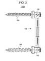
- FIG. 2illustrates a side view of some primary components of one of the intervertebral stabilizers of FIGS. 1A-1B in accordance with one or more embodiments of the present invention
- FIGS. 3A-3Billustrate a side exploded view, and a side assembled view ( FIG. 3B including a partial cross-sectional view of FIG. 3A ), respectively, of a stabilization element of the intervertebral stabilizer system of FIGS. 1A-1B or one or more further embodiments herein;
- FIG. 4illustrates a side, partially cross sectional view of a multilevel intervertebral stabilizer element in accordance with one or more further embodiments of the present invention
- FIGS. 5A-5Billustrate a side view and a cross-sectional view, respectively, of an intermediate sleeve that may be employed with the multilevel intervertebral stabilizer element of FIG. 4 (and/or other embodiments herein);
- FIGS. 6A-6Cillustrate a perspective view and a cross-sectional view, respectively, of alternative intermediate sleeves that may be employed with the multilevel intervertebral stabilizer element of FIG. 4 (and/or other embodiments herein);
- FIG. 7illustrates a perspective view of a further alternative embodiment of a sleeve element that may be employed in an alternative multilevel intervertebral stabilizer element configuration in accordance with one or more embodiments of the present invention
- FIG. 8illustrates a perspective view of a further alternative embodiment of a sleeve element that may be employed in an alternative intervertebral stabilizer element configuration in accordance with one or more embodiments of the present invention
- FIG. 9illustrates a perspective view of a further alternative embodiment of a sleeve element that may be employed in an alternative intervertebral stabilizer element configuration in accordance with one or more embodiments of the present invention
- FIG. 10illustrates a perspective view of an assembly device for use in holding a sleeve element when the sleeve element is coupled to a spring element in accordance with one or more embodiments of the present invention
- FIG. 11illustrates a perspective view of an assembly device for use in holding a spring element when a sleeve element is coupled to the spring element in accordance with one or more embodiments of the present invention.
- FIGS. 1A-Billustrate an embodiment of a spinal stabilizer system 100 in use in accordance with one or more aspects of the present invention.
- the system 100includes two stabilizing elements 100 A, 100 B (also referred to as dynamic stabilizers) that are designed for single level spinal stabilization, preferably from the posterior of the spine.
- the posterior stabilizer system 100is preferably used at the early to moderate stages of the spinal disc degeneration disease process to inhibit posterior disc, vertebral foramen, and inferior vertebral notch collapse with the minimal (semi-constrained) restriction of the vertebral body biological range of motion.
- the stabilizer system 100is preferably sized and shaped for bilateral use on a posterior aspect of the spine.
- the stabilizer 100provides stabilization with respect to adjacent vertebral bones 10 , 12 of the spine.
- the size and shape of the respective stabilizer elements 100 A, 100 Bmay be adapted to fit at any level of the spine, such as the cervical spine, thoracic spine, or lumbar spine.
- unilateral stabilizationis also contemplated and, thus, the system 100 may include a single stabilization element, for example, element 10 A.
- each stabilizer element 100 A, 100 B(element 100 A being shown by way of example) includes first and second anchoring elements 102 , such as pedicle screws, and a spring element 104 coupled to the screws 102 .
- anchoring elements 102need not be pedicle screws; indeed, any of the known techniques of coupling a conventional rod (e.g., a solid rod) may be employed without departing from the invention.
- postsmay be used.
- the stabilizer system 100may employ any pedicle screw system presently utilizing a solid fixation rod of any diameter.
- the depicted embodimentemploys an articulating tulip 106 coupled to each screw 102 that may be moved into various positions with respect to the screw 102 .
- the tulips 106are adapted to receive and clamp respective ends of the spring element 104 .
- the anchors 102secure the respective ends of the spring element 104 to respective portions of two adjacent vertebrae 10 , 12 in order to inhibit posterior disc collapse with minimum restriction of the inter-vertebral movement.
- the respective screws 102may be fixed to a respective articular process of each adjacent vertebrae 10 , 12 , a respective transverse process of each adjacent vertebrae, a respective pedicle of each adjacent vertebrae, or other suitable respective portions of the adjacent vertebrae 10 , 12 .
- the system 100is disposed bilaterally, where one stabilizer element 100 A or 100 B is disposed on each side of the spinous process and attached to respective adjacent vertebrae 10 , 12 in a posterior location as discussed above.
- the spring element 104preferably does not permit compression beyond a certain point at which the respective coils of the spring are in contact with one another. In one or more embodiments, no compressive movement may be allowed, i.e., when there is no distance between the respective coils of the spring and adjacent coils are in contact with one another.
- the dynamic stabilizers 100 A, 100 B located on each side of the spinous processinhibit posterior disc collapse.
- the spring element 104provides extension when tensile forces are applied, the dynamic stabilizers 100 A, 100 B do not substantially limit displacement, rotation, subluxation, flexion, extension, bending, or any combination thereof as between the adjacent vertebrae.
- the spring element 104includes an elongate coil spring 120 having first and second ends 122 , 124 , respectively.
- the first and second ends 122 , 124are utilized as fastening zones for coupling to the respective bone anchors 102 .
- the coil spring 120is preferably hollow all the way through from the first end 122 to the second end 124 , although alternative embodiments of the coil spring 120 may include an interrupted hollow portion therethrough.
- the cross-section of the coil spring 120may take on any shape, such as rectangular, square, triangular, hexagonal, octagonal, polygonal, or any combination thereof. It is preferred that the cross-section is round and the coil spring 120 is of a generally cylindrical configuration.
- a sleeve element 126 Ais preferably disposed at at least one of the first end 122 and the second end 124 of the coil spring 120 .
- the sleeve element 126 Ais preferably sized and shaped to engage the respective ends 122 , 124 by way of threads.
- the sleeve 126 Apreferably includes a threaded bore 128 A, where the threads are preferably of a size and pitch that substantially match the size and pitch of the coils of the coil spring 120 .
- the threadsmay be of another pitch (smaller or larger), so long as the coils of the coil spring 120 conform to the pitch as the sleeve 126 A is threaded onto the ends 122 , 124 thereof.
- the sleeve 126 Amay function as an end cap for the coil spring 120 ; indeed, the threaded bore 128 A does not pass completely through the sleeve 126 A. Thus, the coil spring 120 may bottom out against an end surface of the threaded bore 128 A.
- the sleeve 126 Apreferably includes at least one slot 130 extending from the threaded bore 128 A to a surface of the sleeve 126 A and also extending along at least a portion of the length of the sleeve 126 A.
- the ends 122 , 124 (including the sleeves 126 A) of the spring element 104may be received in the respective tulips 106 of the bone anchors 102 .
- the activation of the tulips 106 to clamp the sleeves 126 A of the spring element 104preferably applies compression forces on the sleeves 126 A and causes respective internal surfaces of the threaded bores 128 A to engage the respective coil springs 120 .
- the sleeve 126 Apreferably includes a post 129 that extends from the bottom of the threaded bore 128 A, and preferably coaxially therewith.
- the post 129is preferably sized and shaped to slide into the hollow portion of the coil spring 120 as the sleeve 126 A is threaded thereon.
- the post 129preferably provides a reactive force to the compressive forces imposed on the coil spring 120 by the threaded bore 128 A as the respective tulip 106 clamps the sleeve 126 A.
- thisprevents the coil spring 120 from collapsing or excessively deforming as compressive forces increase.
- the sleeve 126 A of the spring element 120is of a diameter suitable for reception in the tulip 106 of one of the bone anchors 102 .
- the diameter of the sleeve element 126 Ais preferably about 5 . 5 mm such that widely available bone anchors 102 and tulips 106 (e.g., those designed for conventional rigid rod stabilization/fixation) may be employed to engage the sleeve element 126 A without requiring specialized dimensioning of the tulip 106 .
- other standard diameters (if any) or non-standard diametersmay be employed.
- the cross-section of the sleeve 126 Amay take on any shape, such as rectangular, square, triangular, round, polygonal, or any combination thereof. It is preferred that the cross-section is polygonal, including multi-faceted surfaces to assist in good engagement with the respective tulip 106 .
- the polygonal cross-sectionmay be pentagonal, hexagonal, heptagonal, octagonal, nonagonal, decagonal, undecagonal, dodecagonal, etc.
- the illustrated dodecagonal cross-sectional shapeis preferred.
- the respective lengths of the coil spring 120 and the sleeve 126 Amay vary depending on the specific application of the stabilizer system 100 .
- coil springis approximately three times as long as each of the sleeve elements 126 A.
- the length of the coil spring 120may be customized by the surgeon by cutting same to a desired length (preferably during the operating procedure so that the length may be tailored to the anatomy of the patient).
- the ability to cut the coil spring 120 to lengthreduces inventory while providing significant flexibility in terms of varying a length of the spring element 104 to accommodate differing anatomical conditions.
- the stabilization spring element 104may be employed in single level stabilization and/or multilevel stabilization.
- one or more embodiments of the present inventioncontemplate multilevel spinal stabilization, again from the posterior of the spine.
- the illustrated multilevel spring element 204 A of FIG. 4includes a coil spring 120 , a pair of sleeves 126 A (acting as end caps), and at least one intermediate sleeve 126 B.
- the coil spring 120 of the multi-level embodiment illustrated in FIG. 4would likely be substantially longer than the coil spring 120 of the single level embodiment of FIG. 3B .
- the entirety of the bilateral (or unilateral) stabilization system employing the spring element 204 Ais not shown.
- any number of intermediate sleeves 126 Bmay be employed to achieve stabilization of any number of vertebral levels.
- two-level stabilizationis contemplated.
- the sleeve 126 Bis preferably sized and shaped to thread to an intermediate position on the coil spring 120 between the respective ends 122 , 124 , thereof.
- the sleeve 126 Bpreferably includes a threaded bore 128 B that extends entirely through the sleeve 126 B.
- the threadsare preferably of a size and pitch that substantially match the size and pitch of the coils of the coil spring 120 , or cause the coils of the coil spring 120 to conform as the sleeve is threaded.
- the coil spring 120may be turned through the threaded bore 128 B such that the sleeve 126 B attains any longitudinal intermediate position along the spring 120 .
- the surgeonmay customize the length of the spring element 204 A (e.g., by adjusting the length of the coil spring 120 ) and the position of the sleeve 126 B thereon in order to accommodate the particularities of the patient's anatomy, such as vertebral bone positions.
- the sleeve 126 Balso preferably includes at least one slot 130 extending from the threaded bore 128 B to a surface of the sleeve 126 B and also extending along at least a portion of the length of the sleeve 126 B.
- the activation of the tulip 106 to clamp the sleeve 126 B of the spring element 204 Apreferably applies compression forces on the sleeve 126 B and causes respective internal surfaces of the threaded bore 128 B to engage the coil spring 120 .
- the sleeve 126 Bis preferably of a diameter suitable for reception in the tulip 106 of the respective bone anchor 102 , such as about 5.5 mm to avoid the need for specialized tulip designs—although any diameter may also be employed.
- the cross-section of the sleeve 126 Bmay also take on any shape, such as rectangular, square, triangular, round, polygonal, or any combination thereof, although, like the sleeve 126 A, the cross-section is preferably polygonal, such as dodecagonal.
- an alternative embodimentcontemplates the use of a pair of coil springs 120 coupled together at a single sleeve element 126 B.
- one coil spring 120is threaded into one end of the threaded bore 128 B and the other coil spring 120 is threaded into the opposite end of the threaded bore 128 B.
- the respective the coil springs 120may bottom out against one another, preferably near a central position within the threaded bore 128 B.
- an alternative spring element 204 Bmay be employed to achieve multilevel stabilization.
- the spring element 204 Buses one or more intermediate sleeves 126 C as opposed to the intermediate sleeve(s) 126 B.
- one intermediate sleeve 126 Cis employed for two-level stabilization.
- the intermediate sleeve 126 Cincludes a pair of oppositely directed threaded bores 128 C, 128 D.
- the respective bores 128 C, 128 Dextend from an intermediately disposed separation element, such as a wall 132 .
- the threadsare preferably of a size and pitch that substantially match the size and pitch of the coils of the coil spring 120 , or cause the coils of the coil spring 120 to conform as the sleeve is threaded.
- a pair of coil springs 120is preferably employed, one coil spring 120 A being threaded into the threaded bore 128 C and the other coil spring 120 D being threaded into the threaded bore 128 D.
- the respective coil springs 120 A, 120 Bmay bottom out against the opposing end surfaces of the wall 132 .
- the sleeve 126 Calso preferably includes at least one slot 130 A extending from at least one (and preferably both) of the threaded bore 128 C, 128 D to a surface of the sleeve 126 C. As best seen in FIG. 6A , it is preferred that a plurality of such slots 130 A extend along the length of the sleeve 126 C, toward respective ends thereof.
- the activation of the respective tulip 106 (not shown) to clamp the sleeve 126 C of the spring element 204 BApreferably applies compression forces on the sleeve 126 C and causes respective internal surfaces of the threaded bores 128 C, 128 D to engage the coil springs 120 A, 120 B.
- the sleeve 126 Cpreferably includes at least one post 129 that extends from the wall 132 of one or both of the threaded bores 128 C, 128 D.
- the post 129preferably extends coaxially within the threaded bore 128 C and/or 128 D. It is most preferred that respective posts 129 A, 129 B extend from respective sides of the wall 132 , coaxially within the respective threaded bores 128 C, 128 D.
- Each post 129 A, 129 Bis preferably sized and shaped to slide into the hollow portion of the associated coil spring 120 A, 120 B as the sleeve 126 C is threaded thereon.
- each post 129preferably provides a reactive force to the compressive forces imposed on the coil springs 120 A, 120 B by the threaded bores 128 C, 128 D as the tulip 106 clamps the sleeve 126 C.
- the sleeve 126 Cis preferably of a diameter suitable for reception in the tulip 106 of the respective bone anchor 102 , such as about 5.5 mm to avoid the need for specialized tulip designs—although any diameter may also be employed.
- the cross-section of the sleeve 126 Cmay also take on any shape, such as rectangular, square, triangular, round, polygonal, or any combination thereof, although, like the sleeve 126 A, the cross-section is preferably polygonal, such as dodecagonal.
- Additional levels of stabilizationmay be achieved by cascading respective coil springs 120 using one or more of the intermediate sleeves 126 C.
- FIG. 6Calternative intermediate sleeves 126 D and 126 E, and alternative end sleeve 126 F are illustrated. Any of the intermediate sleeves and/or end sleeves of the embodiments herein may be substituted with the sleeves of FIG. 6C in accordance with further aspects of the present invention.
- the sleeves 126 D, 126 E, and 126 Finclude non-threaded (e.g., smooth or rough) bores 127 as opposed to the threaded bores 128 of the other embodiments herein. While the intermediate sleeve 126 D includes a through bore 127 , the intermediate sleeve 126 E includes respective bores 127 A, 127 B extending from a central wall 132 .
- the bores 127are preferably of a size that substantially matches the size of the coils of the coil spring 120 , or cause the coils of the coil spring 120 to conform as the sleeve is pressed or slid onto the coil spring 120 .
- the respective coil springs 120 A, 120 Bmay bottom out against one another (if sleeve 126 D is employed) or against the opposing end surfaces of the wall 132 (if sleeve 126 E is employed).
- the sleeve 126 D, 126 E, and 126 Falso preferably includes at least one slot 130 extending from at least one (and preferably both) of the bore 127 to a surface of the sleeve 126 . It is preferred that a plurality of such slots 130 extend along the length of the sleeve 126 , toward respective ends thereof.
- the activation of the respective tulip 106 (not shown) to clamp the sleeve 126 of the spring elemente.g., similar to spring element 204 B
- the sleeve 126 Epreferably includes at least one post 129 that extends from the wall 132 of one or both of the bores 127 A, 127 B.
- the post 129preferably extends coaxially within the bore 127 A and/or 127 B. It is most preferred that respective posts 129 A, 129 B extend from respective sides of the wall 132 , coaxially within the respective bores 127 A, 127 B.
- Each post 129 A, 129 Bis preferably sized and shaped to slide into the hollow portion of the associated coil spring 120 A, 120 B as the sleeve 126 E is slid thereon.
- each post 129preferably provides a reactive force to the compressive forces imposed on the coil springs 120 A, 120 B by the bores 127 A, 127 B as the tulip 106 clamps the sleeve 126 E.
- one or more embodiments of the present inventionmay employ a spring element 304 A, which includes a combination of a sleeve element 126 A and a relatively rigid rod 140 (such as a solid rod).
- a spring element 304 Awhich includes a combination of a sleeve element 126 A and a relatively rigid rod 140 (such as a solid rod).
- a relatively rigid rod 140such as a solid rod.
- Multilevel stabilizationmay be readily achieved by threading a coil spring 120 into the sleeve element 126 A.
- the resulting spring element 304 Aincludes a rigid section (via the rod 140 ) and a flexible section (via the coil spring 120 ).
- the rod 140may provide a rigid stabilization at one or more levels (dependent on the length of the rod 140 ), while the coil spring 120 may provide dynamic stabilization at the next level (and/or subsequent levels depending on the length of the coil spring 120 ). Additional levels of stabilization may be achieved by cascading respective coil springs 120 and/or rods 140 using one or more of the sleeve embodiments described herein.
- one or more embodiments of the present inventionmay employ a spring element 404 A, which includes one or more sleeve elements 126 A, one or more coupling plates 150 , and at least one coil spring 120 .
- the coupling plate 150is connected, at an end 152 thereof, to an end of a sleeve element, such as the sleeve element 126 A.
- a sleeve elementsuch as the sleeve element 126 A.
- any of the other sleeve element embodimentsmay also be employed.
- the plate 150includes an aperture 154 therethrough for receiving a bone screw (not shown). The aperture is preferably elongate to permit some adjustment in the position of the plate 150 relative to the bone screw.
- a conventional bone screwis employed that includes a beveled head to engage a chamfer 156 of the aperture 154 .
- the bone screwis operable to fix the sleeve 126 A and one end of the spring element 404 A to the vertebral bone.
- Another bone screwmay be used to fix the other coupling plate 150 of the spring element 404 A to an adjacent vertebral bone.
- the illustrated embodiment of the spring element 404 Ais for single level stabilization. Multilevel stabilization may readily be achieved using one or more intermediate sleeves (e.g., sleeves 126 B, 126 C) and one or more coil springs 120 and/or rods 140 .
- the spring element 404 Amay employ a coupling plate 160 as an alternative to the coupling plate 150 of FIG. 8 .
- the coupling plate 160includes a plurality of apertures 162 disposed in a linear arrangement therealong. The surgeon may select one or more of the apertures 162 for use in securing the coupling plate 160 to the vertebral bone based on the anatomy of the patient.
- a conventional bone screwis preferably employed (which may include a beveled head) to engage a chamfer 164 of the aperture 162 and secure the plate 160 to the bone. If desired, the surgeon may cut the coupling plate 160 to a custom size for the patient. Similar to the discussion of the spring element 404 A of FIG.
- the spring element 404 Aemploys one or more coupling plates 160 , single level stabilization or multilevel stabilization may be achieved using the appropriate sleeves, coil springs, and/or rods.
- the coupling plate 160may be used for rigid stabilization of a level by using same to span an intervertebral space.
- the coupling plate 160may be fastened to adjacent vertebral bones by way of apertures 162 on either end of the plate 160 .
- the spring element 204 A( FIG. 4 ) may be assembled using the sleeve wrench 500 of FIG. 10 and the spring holder 550 of FIG. 11 .
- the sleeve wrenchincludes a central aperture 502 sized and shaped to slideably receive a sleeve 126 (which may be any of the sleeve embodiments herein).
- the aperture 502preferably includes a faceted inner surface that complements the contour of the sleeve 126 .
- the aperture 502 of the wrench 500preferably includes a corresponding contour, although it need not be of exactly the same contour as the sleeve 126 .
- the overall shape of the wrench 500is preferably of generally flat-circular construction such that the surgeon (or an assistant) may easily grasp same and turn the sleeve 126 onto the coil spring 120 .
- the wrench 500includes a plurality of relief cuts or impressions 504 to assist in grasping same.
- the wrench 500may alternatively or additionally include knurling or the like.
- the spring holder 550is preferably operable to clamp the coil spring 120 such that it does not turn when the sleeve 126 is being threaded thereon.
- the spring holder 550preferably includes a pair of actuators 552 , such as in the form of lever arms that communicate with a clamp element 554 .
- the coil spring 120is preferably slid into or otherwise placed into the clamp element 554 . As the actuators 552 are pressed toward one another, an interior surface of the clamp element 554 collapses, thereby gripping the coil spring 120 .
- the components discussed aboveare formed from CP Titanium or Titanium Alloy, Stainless Steel, Cobalt Chromium Alloy, Plastics and/or other biologically acceptable materials.
- the tools of FIGS. 10 and 11may be formed from non-biologically acceptable materials, such as steel.
- the portions of the devicemay be produced in the range of sizes and length adequate to the requirements.
Landscapes
- Health & Medical Sciences (AREA)
- Orthopedic Medicine & Surgery (AREA)
- Neurology (AREA)
- Life Sciences & Earth Sciences (AREA)
- Surgery (AREA)
- Heart & Thoracic Surgery (AREA)
- Engineering & Computer Science (AREA)
- Biomedical Technology (AREA)
- Nuclear Medicine, Radiotherapy & Molecular Imaging (AREA)
- Medical Informatics (AREA)
- Molecular Biology (AREA)
- Animal Behavior & Ethology (AREA)
- General Health & Medical Sciences (AREA)
- Public Health (AREA)
- Veterinary Medicine (AREA)
- Surgical Instruments (AREA)
- Prostheses (AREA)
Abstract
Description
- posterior disc collapse inhibited with minimal restriction of the vertebral body biological ROM;
- minimum pre-determined distance between bone anchors (or any attachment points) maintained without limiting displacement, rotation, subluxation, flexion, extension, bending or any combination thereof;
- locking mechanism accommodating any existing screw system presently used for solid rod fixation;
- hybrid multilevel system configurations permitted;
- controlled system flexibility permitted;
- cross-section can be circular, square, rectangular, polygonal and any combination thereof; and
- rigidity in specific direction controlled.
Claims (16)
Priority Applications (2)
| Application Number | Priority Date | Filing Date | Title |
|---|---|---|---|
| US11/325,104US7556639B2 (en) | 2005-03-03 | 2006-01-04 | Methods and apparatus for vertebral stabilization using sleeved springs |
| PCT/US2006/001698WO2006096240A2 (en) | 2005-03-03 | 2006-01-19 | Methods and apparatus for vertebral stabilization using sleeved springs |
Applications Claiming Priority (2)
| Application Number | Priority Date | Filing Date | Title |
|---|---|---|---|
| US65836505P | 2005-03-03 | 2005-03-03 | |
| US11/325,104US7556639B2 (en) | 2005-03-03 | 2006-01-04 | Methods and apparatus for vertebral stabilization using sleeved springs |
Publications (2)
| Publication Number | Publication Date |
|---|---|
| US20060229612A1 US20060229612A1 (en) | 2006-10-12 |
| US7556639B2true US7556639B2 (en) | 2009-07-07 |
Family
ID=36953787
Family Applications (1)
| Application Number | Title | Priority Date | Filing Date |
|---|---|---|---|
| US11/325,104Active2027-02-13US7556639B2 (en) | 2005-03-03 | 2006-01-04 | Methods and apparatus for vertebral stabilization using sleeved springs |
Country Status (2)
| Country | Link |
|---|---|
| US (1) | US7556639B2 (en) |
| WO (1) | WO2006096240A2 (en) |
Cited By (57)
| Publication number | Priority date | Publication date | Assignee | Title |
|---|---|---|---|---|
| US20050124991A1 (en)* | 2003-12-05 | 2005-06-09 | Tae-Ahn Jahng | Method and apparatus for flexible fixation of a spine |
| US20050177157A1 (en)* | 2003-09-24 | 2005-08-11 | N Spine, Inc. | Method and apparatus for flexible fixation of a spine |
| US20070118122A1 (en)* | 2005-11-18 | 2007-05-24 | Life Spine, Llc | Dynamic spinal stabilization device and systems |
| US20070233095A1 (en)* | 2004-10-07 | 2007-10-04 | Schlaepfer Fridolin J | Device for dynamic stabilization of bones or bone fragments |
| US20080045951A1 (en)* | 2006-08-16 | 2008-02-21 | Depuy Spine, Inc. | Modular multi-level spine stabilization system and method |
| US20080234746A1 (en)* | 2003-09-24 | 2008-09-25 | N Spine, Inc. | Spinal stabilization device |
| US20090054932A1 (en)* | 2007-08-23 | 2009-02-26 | Butler Michael S | Resilient Spinal Rod System With Controllable Angulation |
| US7815665B2 (en) | 2003-09-24 | 2010-10-19 | N Spine, Inc. | Adjustable spinal stabilization system |
| US7815663B2 (en) | 2006-01-27 | 2010-10-19 | Warsaw Orthopedic, Inc. | Vertebral rods and methods of use |
| US20100318130A1 (en)* | 2007-12-15 | 2010-12-16 | Parlato Brian D | Flexible rod assembly for spinal fixation |
| US20110015678A1 (en)* | 2004-11-23 | 2011-01-20 | Jackson Roger P | Spinal fixation tool set and method |
| US8066739B2 (en) | 2004-02-27 | 2011-11-29 | Jackson Roger P | Tool system for dynamic spinal implants |
| US20110313459A1 (en)* | 2003-05-02 | 2011-12-22 | Yale University | Dynamic Spine Stabilizer |
| US8092500B2 (en) | 2007-05-01 | 2012-01-10 | Jackson Roger P | Dynamic stabilization connecting member with floating core, compression spacer and over-mold |
| US8100915B2 (en) | 2004-02-27 | 2012-01-24 | Jackson Roger P | Orthopedic implant rod reduction tool set and method |
| US8105368B2 (en) | 2005-09-30 | 2012-01-31 | Jackson Roger P | Dynamic stabilization connecting member with slitted core and outer sleeve |
| US8118840B2 (en) | 2009-02-27 | 2012-02-21 | Warsaw Orthopedic, Inc. | Vertebral rod and related method of manufacture |
| US20120184994A1 (en)* | 2006-02-03 | 2012-07-19 | Thomas Zehnder | Vertebral column implant |
| US8353932B2 (en) | 2005-09-30 | 2013-01-15 | Jackson Roger P | Polyaxial bone anchor assembly with one-piece closure, pressure insert and plastic elongate member |
| US8366745B2 (en) | 2007-05-01 | 2013-02-05 | Jackson Roger P | Dynamic stabilization assembly having pre-compressed spacers with differential displacements |
| US8394133B2 (en) | 2004-02-27 | 2013-03-12 | Roger P. Jackson | Dynamic fixation assemblies with inner core and outer coil-like member |
| US8475498B2 (en) | 2007-01-18 | 2013-07-02 | Roger P. Jackson | Dynamic stabilization connecting member with cord connection |
| US8545538B2 (en) | 2005-12-19 | 2013-10-01 | M. Samy Abdou | Devices and methods for inter-vertebral orthopedic device placement |
| US8556938B2 (en) | 2009-06-15 | 2013-10-15 | Roger P. Jackson | Polyaxial bone anchor with non-pivotable retainer and pop-on shank, some with friction fit |
| US8591515B2 (en) | 2004-11-23 | 2013-11-26 | Roger P. Jackson | Spinal fixation tool set and method |
| US8591560B2 (en) | 2005-09-30 | 2013-11-26 | Roger P. Jackson | Dynamic stabilization connecting member with elastic core and outer sleeve |
| US8623057B2 (en) | 2003-09-24 | 2014-01-07 | DePuy Synthes Products, LLC | Spinal stabilization device |
| US8641734B2 (en) | 2009-02-13 | 2014-02-04 | DePuy Synthes Products, LLC | Dual spring posterior dynamic stabilization device with elongation limiting elastomers |
| US8845649B2 (en) | 2004-09-24 | 2014-09-30 | Roger P. Jackson | Spinal fixation tool set and method for rod reduction and fastener insertion |
| US8979904B2 (en) | 2007-05-01 | 2015-03-17 | Roger P Jackson | Connecting member with tensioned cord, low profile rigid sleeve and spacer with torsion control |
| US8992576B2 (en) | 2008-12-17 | 2015-03-31 | DePuy Synthes Products, LLC | Posterior spine dynamic stabilizer |
| US9011494B2 (en) | 2009-09-24 | 2015-04-21 | Warsaw Orthopedic, Inc. | Composite vertebral rod system and methods of use |
| US9050139B2 (en) | 2004-02-27 | 2015-06-09 | Roger P. Jackson | Orthopedic implant rod reduction tool set and method |
| US9216039B2 (en) | 2004-02-27 | 2015-12-22 | Roger P. Jackson | Dynamic spinal stabilization assemblies, tool set and method |
| US9216041B2 (en) | 2009-06-15 | 2015-12-22 | Roger P. Jackson | Spinal connecting members with tensioned cords and rigid sleeves for engaging compression inserts |
| US9232968B2 (en) | 2007-12-19 | 2016-01-12 | DePuy Synthes Products, Inc. | Polymeric pedicle rods and methods of manufacturing |
| US9320543B2 (en) | 2009-06-25 | 2016-04-26 | DePuy Synthes Products, Inc. | Posterior dynamic stabilization device having a mobile anchor |
| US9445844B2 (en) | 2010-03-24 | 2016-09-20 | DePuy Synthes Products, Inc. | Composite material posterior dynamic stabilization spring rod |
| US9451989B2 (en) | 2007-01-18 | 2016-09-27 | Roger P Jackson | Dynamic stabilization members with elastic and inelastic sections |
| US9743957B2 (en) | 2004-11-10 | 2017-08-29 | Roger P. Jackson | Polyaxial bone screw with shank articulation pressure insert and method |
| US10039578B2 (en) | 2003-12-16 | 2018-08-07 | DePuy Synthes Products, Inc. | Methods and devices for minimally invasive spinal fixation element placement |
| US10258382B2 (en) | 2007-01-18 | 2019-04-16 | Roger P. Jackson | Rod-cord dynamic connection assemblies with slidable bone anchor attachment members along the cord |
| US10299839B2 (en) | 2003-12-16 | 2019-05-28 | Medos International Sárl | Percutaneous access devices and bone anchor assemblies |
| US10383660B2 (en) | 2007-05-01 | 2019-08-20 | Roger P. Jackson | Soft stabilization assemblies with pretensioned cords |
| US10543107B2 (en) | 2009-12-07 | 2020-01-28 | Samy Abdou | Devices and methods for minimally invasive spinal stabilization and instrumentation |
| US10548740B1 (en) | 2016-10-25 | 2020-02-04 | Samy Abdou | Devices and methods for vertebral bone realignment |
| US10575961B1 (en) | 2011-09-23 | 2020-03-03 | Samy Abdou | Spinal fixation devices and methods of use |
| US10695105B2 (en) | 2012-08-28 | 2020-06-30 | Samy Abdou | Spinal fixation devices and methods of use |
| US10729469B2 (en) | 2006-01-09 | 2020-08-04 | Roger P. Jackson | Flexible spinal stabilization assembly with spacer having off-axis core member |
| US10857003B1 (en) | 2015-10-14 | 2020-12-08 | Samy Abdou | Devices and methods for vertebral stabilization |
| US10918498B2 (en) | 2004-11-24 | 2021-02-16 | Samy Abdou | Devices and methods for inter-vertebral orthopedic device placement |
| US10973648B1 (en) | 2016-10-25 | 2021-04-13 | Samy Abdou | Devices and methods for vertebral bone realignment |
| US11006982B2 (en) | 2012-02-22 | 2021-05-18 | Samy Abdou | Spinous process fixation devices and methods of use |
| US11173040B2 (en) | 2012-10-22 | 2021-11-16 | Cogent Spine, LLC | Devices and methods for spinal stabilization and instrumentation |
| US11179248B2 (en) | 2018-10-02 | 2021-11-23 | Samy Abdou | Devices and methods for spinal implantation |
| US11419642B2 (en) | 2003-12-16 | 2022-08-23 | Medos International Sarl | Percutaneous access devices and bone anchor assemblies |
| US12110722B2 (en) | 2019-06-28 | 2024-10-08 | Magna Closures Inc. | Counterbalance mechanism with optional watershield, kicker spring, friction bearing, and fail safe spring retention mechanism |
Families Citing this family (76)
| Publication number | Priority date | Publication date | Assignee | Title |
|---|---|---|---|---|
| FR2812185B1 (en) | 2000-07-25 | 2003-02-28 | Spine Next Sa | SEMI-RIGID CONNECTION PIECE FOR RACHIS STABILIZATION |
| US7833250B2 (en) | 2004-11-10 | 2010-11-16 | Jackson Roger P | Polyaxial bone screw with helically wound capture connection |
| US8876868B2 (en) | 2002-09-06 | 2014-11-04 | Roger P. Jackson | Helical guide and advancement flange with radially loaded lip |
| WO2006052796A2 (en) | 2004-11-10 | 2006-05-18 | Jackson Roger P | Helical guide and advancement flange with break-off extensions |
| US7713287B2 (en)* | 2003-05-02 | 2010-05-11 | Applied Spine Technologies, Inc. | Dynamic spine stabilizer |
| US7377923B2 (en) | 2003-05-22 | 2008-05-27 | Alphatec Spine, Inc. | Variable angle spinal screw assembly |
| US8926670B2 (en) | 2003-06-18 | 2015-01-06 | Roger P. Jackson | Polyaxial bone screw assembly |
| US8366753B2 (en) | 2003-06-18 | 2013-02-05 | Jackson Roger P | Polyaxial bone screw assembly with fixed retaining structure |
| US7967850B2 (en) | 2003-06-18 | 2011-06-28 | Jackson Roger P | Polyaxial bone anchor with helical capture connection, insert and dual locking assembly |
| US7588590B2 (en) | 2003-12-10 | 2009-09-15 | Facet Solutions, Inc | Spinal facet implant with spherical implant apposition surface and bone bed and methods of use |
| US8562649B2 (en) | 2004-02-17 | 2013-10-22 | Gmedelaware 2 Llc | System and method for multiple level facet joint arthroplasty and fusion |
| US8333789B2 (en) | 2007-01-10 | 2012-12-18 | Gmedelaware 2 Llc | Facet joint replacement |
| US11241261B2 (en) | 2005-09-30 | 2022-02-08 | Roger P Jackson | Apparatus and method for soft spinal stabilization using a tensionable cord and releasable end structure |
| US7507242B2 (en) | 2004-06-02 | 2009-03-24 | Facet Solutions | Surgical measurement and resection framework |
| US8926672B2 (en) | 2004-11-10 | 2015-01-06 | Roger P. Jackson | Splay control closure for open bone anchor |
| US9168069B2 (en) | 2009-06-15 | 2015-10-27 | Roger P. Jackson | Polyaxial bone anchor with pop-on shank and winged insert with lower skirt for engaging a friction fit retainer |
| US8444681B2 (en) | 2009-06-15 | 2013-05-21 | Roger P. Jackson | Polyaxial bone anchor with pop-on shank, friction fit retainer and winged insert |
| US9980753B2 (en) | 2009-06-15 | 2018-05-29 | Roger P Jackson | pivotal anchor with snap-in-place insert having rotation blocking extensions |
| WO2006057837A1 (en) | 2004-11-23 | 2006-06-01 | Jackson Roger P | Spinal fixation tool attachment structure |
| WO2006066053A1 (en)* | 2004-12-15 | 2006-06-22 | Stryker Spine | Spinal rods having segments of different elastic properties and methods of using them |
| EP1719468A1 (en)* | 2004-12-17 | 2006-11-08 | Zimmer GmbH | Intervertebral stabilization system |
| US10076361B2 (en) | 2005-02-22 | 2018-09-18 | Roger P. Jackson | Polyaxial bone screw with spherical capture, compression and alignment and retention structures |
| US7901437B2 (en) | 2007-01-26 | 2011-03-08 | Jackson Roger P | Dynamic stabilization member with molded connection |
| US20060264937A1 (en)* | 2005-05-04 | 2006-11-23 | White Patrick M | Mobile spine stabilization device |
| US7811309B2 (en)* | 2005-07-26 | 2010-10-12 | Applied Spine Technologies, Inc. | Dynamic spine stabilization device with travel-limiting functionality |
| US7713288B2 (en)* | 2005-08-03 | 2010-05-11 | Applied Spine Technologies, Inc. | Spring junction and assembly methods for spinal device |
| DE602005007223D1 (en)* | 2005-08-24 | 2008-07-10 | Biedermann Motech Gmbh | Rod-shaped element for use in spine or trauma surgery and stabilization device with such an element |
| US20070093814A1 (en)* | 2005-10-11 | 2007-04-26 | Callahan Ronald Ii | Dynamic spinal stabilization systems |
| US20070093813A1 (en)* | 2005-10-11 | 2007-04-26 | Callahan Ronald Ii | Dynamic spinal stabilizer |
| US20070093815A1 (en)* | 2005-10-11 | 2007-04-26 | Callahan Ronald Ii | Dynamic spinal stabilizer |
| US7682376B2 (en) | 2006-01-27 | 2010-03-23 | Warsaw Orthopedic, Inc. | Interspinous devices and methods of use |
| US7578849B2 (en) | 2006-01-27 | 2009-08-25 | Warsaw Orthopedic, Inc. | Intervertebral implants and methods of use |
| US20070270821A1 (en)* | 2006-04-28 | 2007-11-22 | Sdgi Holdings, Inc. | Vertebral stabilizer |
| WO2008003047A2 (en) | 2006-06-28 | 2008-01-03 | Synthes (U.S.A.) | Dynamic fixation system |
| US8435268B2 (en)* | 2007-01-19 | 2013-05-07 | Reduction Technologies, Inc. | Systems, devices and methods for the correction of spinal deformities |
| US20080195153A1 (en)* | 2007-02-08 | 2008-08-14 | Matthew Thompson | Dynamic spinal deformity correction |
| US8926667B2 (en)* | 2007-02-09 | 2015-01-06 | Transcendental Spine, Llc | Connector |
| US8012177B2 (en) | 2007-02-12 | 2011-09-06 | Jackson Roger P | Dynamic stabilization assembly with frusto-conical connection |
| US9138263B2 (en)* | 2007-02-14 | 2015-09-22 | William R. Krause | Flexible spine components |
| CA2690038C (en) | 2007-05-31 | 2012-11-27 | Roger P. Jackson | Dynamic stabilization connecting member with pre-tensioned solid core |
| FR2930886A1 (en)* | 2007-07-24 | 2009-11-13 | Henry Graf | EXTRA-DISCAL ASSEMBLY FOR INTERNETEBRAL PROTHERMAL STABILIZATION |
| US8080038B2 (en)* | 2007-08-17 | 2011-12-20 | Jmea Corporation | Dynamic stabilization device for spine |
| US20090088782A1 (en)* | 2007-09-28 | 2009-04-02 | Missoum Moumene | Flexible Spinal Rod With Elastomeric Jacket |
| US20090093820A1 (en)* | 2007-10-09 | 2009-04-09 | Warsaw Orthopedic, Inc. | Adjustable spinal stabilization systems |
| EP2047810B1 (en)* | 2007-10-11 | 2011-09-28 | BIEDERMANN MOTECH GmbH | Modular rod system for spinal stabilization |
| US20090099608A1 (en)* | 2007-10-12 | 2009-04-16 | Aesculap Implant Systems, Inc. | Rod assembly for dynamic posterior stabilization |
| US8911477B2 (en) | 2007-10-23 | 2014-12-16 | Roger P. Jackson | Dynamic stabilization member with end plate support and cable core extension |
| KR100837108B1 (en)* | 2008-01-11 | 2008-06-11 | 최길운 | Flexible Rod for Spinal Fixation |
| US20090326582A1 (en)* | 2008-04-10 | 2009-12-31 | Marcus Songer | Dynamic Rod |
| US8034083B2 (en)* | 2008-05-01 | 2011-10-11 | Custom Spine, Inc. | Artificial ligament assembly |
| DE602008004213D1 (en)* | 2008-05-06 | 2011-02-10 | Biedermann Motech Gmbh | Rod-shaped implant, in particular for the dynamic stabilization of the spine |
| US9017384B2 (en)* | 2008-05-13 | 2015-04-28 | Stryker Spine | Composite spinal rod |
| US8043340B1 (en)* | 2008-06-09 | 2011-10-25 | Melvin Law | Dynamic spinal stabilization system |
| AU2010260521C1 (en) | 2008-08-01 | 2013-08-01 | Roger P. Jackson | Longitudinal connecting member with sleeved tensioned cords |
| TWI463967B (en)* | 2009-01-08 | 2014-12-11 | Spinal fixation system | |
| EP2440145A4 (en)* | 2009-06-08 | 2013-12-11 | Reduction Technologies Inc | Systems, methods and devices for correcting spinal deformities |
| US9668771B2 (en) | 2009-06-15 | 2017-06-06 | Roger P Jackson | Soft stabilization assemblies with off-set connector |
| US8998959B2 (en) | 2009-06-15 | 2015-04-07 | Roger P Jackson | Polyaxial bone anchors with pop-on shank, fully constrained friction fit retainer and lock and release insert |
| US11229457B2 (en) | 2009-06-15 | 2022-01-25 | Roger P. Jackson | Pivotal bone anchor assembly with insert tool deployment |
| CN103826560A (en) | 2009-06-15 | 2014-05-28 | 罗杰.P.杰克逊 | Polyaxial Bone Anchor with Socket Stem and Winged Inserts with Friction Fit Compression Collars |
| US20110009906A1 (en)* | 2009-07-13 | 2011-01-13 | Zimmer Spine, Inc. | Vertebral stabilization transition connector |
| US8870923B2 (en)* | 2009-11-06 | 2014-10-28 | Marc E. Richelsoph | Rod to rod connector with load sharing |
| AU2011324058A1 (en) | 2010-11-02 | 2013-06-20 | Roger P. Jackson | Polyaxial bone anchor with pop-on shank and pivotable retainer |
| US9039765B2 (en)* | 2011-01-21 | 2015-05-26 | Warsaw Orhtopedic, Inc. | Implant system and method for stabilization of a sacro-iliac joint |
| JP5865479B2 (en) | 2011-03-24 | 2016-02-17 | ロジャー・ピー・ジャクソン | Multiaxial bone anchor with compound joint and pop-mounted shank |
| EP2887892A1 (en)* | 2012-08-21 | 2015-07-01 | Montavon, Lorraine | Spring and device for stabilizing human or animal bones |
| US8911478B2 (en) | 2012-11-21 | 2014-12-16 | Roger P. Jackson | Splay control closure for open bone anchor |
| US10058354B2 (en) | 2013-01-28 | 2018-08-28 | Roger P. Jackson | Pivotal bone anchor assembly with frictional shank head seating surfaces |
| US8852239B2 (en) | 2013-02-15 | 2014-10-07 | Roger P Jackson | Sagittal angle screw with integral shank and receiver |
| US9700435B2 (en) | 2013-03-14 | 2017-07-11 | Warsaw Orthopedic, Inc. | Surgical delivery system and method |
| US9566092B2 (en) | 2013-10-29 | 2017-02-14 | Roger P. Jackson | Cervical bone anchor with collet retainer and outer locking sleeve |
| US9717533B2 (en) | 2013-12-12 | 2017-08-01 | Roger P. Jackson | Bone anchor closure pivot-splay control flange form guide and advancement structure |
| US9451993B2 (en) | 2014-01-09 | 2016-09-27 | Roger P. Jackson | Bi-radial pop-on cervical bone anchor |
| US10064658B2 (en) | 2014-06-04 | 2018-09-04 | Roger P. Jackson | Polyaxial bone anchor with insert guides |
| US9597119B2 (en) | 2014-06-04 | 2017-03-21 | Roger P. Jackson | Polyaxial bone anchor with polymer sleeve |
| US10945763B2 (en)* | 2018-05-31 | 2021-03-16 | Texas Scottish Rite Hospital For Children | Orthopedic spring hinge system and methods thereof |
Citations (27)
| Publication number | Priority date | Publication date | Assignee | Title |
|---|---|---|---|---|
| US4733657A (en)* | 1984-04-16 | 1988-03-29 | Patrick Kluger | Apparatus for aligning a spinal column having damaged vertebrae |
| US5180393A (en) | 1990-09-21 | 1993-01-19 | Polyclinique De Bourgogne & Les Hortensiad | Artificial ligament for the spine |
| WO1996031167A1 (en)* | 1995-04-05 | 1996-10-10 | Chauvin Jean Luc | Device for straightening and supporting a backbone |
| US5672175A (en) | 1993-08-27 | 1997-09-30 | Martin; Jean Raymond | Dynamic implanted spinal orthosis and operative procedure for fitting |
| US5733284A (en) | 1993-08-27 | 1998-03-31 | Paulette Fairant | Device for anchoring spinal instrumentation on a vertebra |
| EP1080692A1 (en)* | 1999-09-03 | 2001-03-07 | Bone & Joint Research S.A. | Flexible connection for bone anchor means |
| US6293949B1 (en) | 2000-03-01 | 2001-09-25 | Sdgi Holdings, Inc. | Superelastic spinal stabilization system and method |
| FR2806615A1 (en)* | 2000-03-21 | 2001-09-28 | Cremascolli Ortho S A | Vertebral fracture reducing apparatus has fixings shaped to receive cylindrical components holding linking rods |
| US20020026194A1 (en) | 1999-04-16 | 2002-02-28 | Morrison Matthew M. | Multi-axial bone anchor system |
| GB2382304A (en) | 2001-10-10 | 2003-05-28 | Dilip Kumar Sengupta | An assembly for soft stabilisation of vertebral bodies of the spine |
| US20030109880A1 (en) | 2001-08-01 | 2003-06-12 | Showa Ika Kohgyo Co., Ltd. | Bone connector |
| US20030220643A1 (en)* | 2002-05-24 | 2003-11-27 | Ferree Bret A. | Devices to prevent spinal extension |
| US20040002708A1 (en) | 2002-05-08 | 2004-01-01 | Stephen Ritland | Dynamic fixation device and method of use |
| US20040049190A1 (en) | 2002-08-09 | 2004-03-11 | Biedermann Motech Gmbh | Dynamic stabilization device for bones, in particular for vertebrae |
| US20040236329A1 (en) | 2003-05-02 | 2004-11-25 | Panjabi Manohar M. | Dynamic spine stabilizer |
| US20040236327A1 (en) | 2003-05-23 | 2004-11-25 | Paul David C. | Spine stabilization system |
| US6835205B2 (en) | 2000-04-04 | 2004-12-28 | Spinalabs, Llc | Devices and methods for the treatment of spinal disorders |
| US20040267260A1 (en) | 2003-06-16 | 2004-12-30 | Thomas Mack | Implant for correction and stabilization of the spinal column |
| US20050033295A1 (en) | 2003-08-08 | 2005-02-10 | Paul Wisnewski | Implants formed of shape memory polymeric material for spinal fixation |
| DE10348329B3 (en) | 2003-10-17 | 2005-02-17 | Biedermann Motech Gmbh | Rod-shaped element used in spinal column and accident surgery for connecting two bone-anchoring elements comprises a rigid section and an elastic section that are made in one piece |
| US20050056979A1 (en) | 2001-12-07 | 2005-03-17 | Mathys Medizinaltechnik Ag | Damping element and device for stabilisation of adjacent vertebral bodies |
| US20050065516A1 (en) | 2003-09-24 | 2005-03-24 | Tae-Ahn Jahng | Method and apparatus for flexible fixation of a spine |
| US20050149020A1 (en) | 2003-12-05 | 2005-07-07 | Tae-Ahn Jahng | Method and apparatus for flexible fixation of a spine |
| US20050154390A1 (en)* | 2003-11-07 | 2005-07-14 | Lutz Biedermann | Stabilization device for bones comprising a spring element and manufacturing method for said spring element |
| US20050203519A1 (en) | 2004-03-09 | 2005-09-15 | Jurgen Harms | Rod-like element for application in spinal or trauma surgery, and stabilization device with such a rod-like element |
| DE102004018621A1 (en)* | 2004-04-16 | 2005-11-10 | Biedermann Motech Gmbh | Elastic element e.g. for stabilizing device for bones and method of fabrication of such an elastic element, has a cylindrical body with two ends and flexible section between ends and section is made from two coil springs |
| US20060142758A1 (en)* | 2002-09-11 | 2006-06-29 | Dominique Petit | Linking element for dynamically stabilizing a spinal fixing system and spinal fixing system comprising same |
- 2006
- 2006-01-04USUS11/325,104patent/US7556639B2/enactiveActive
- 2006-01-19WOPCT/US2006/001698patent/WO2006096240A2/enactiveApplication Filing
Patent Citations (32)
| Publication number | Priority date | Publication date | Assignee | Title |
|---|---|---|---|---|
| US4733657A (en)* | 1984-04-16 | 1988-03-29 | Patrick Kluger | Apparatus for aligning a spinal column having damaged vertebrae |
| US5180393A (en) | 1990-09-21 | 1993-01-19 | Polyclinique De Bourgogne & Les Hortensiad | Artificial ligament for the spine |
| US5672175A (en) | 1993-08-27 | 1997-09-30 | Martin; Jean Raymond | Dynamic implanted spinal orthosis and operative procedure for fitting |
| US5733284A (en) | 1993-08-27 | 1998-03-31 | Paulette Fairant | Device for anchoring spinal instrumentation on a vertebra |
| WO1996031167A1 (en)* | 1995-04-05 | 1996-10-10 | Chauvin Jean Luc | Device for straightening and supporting a backbone |
| US20020026194A1 (en) | 1999-04-16 | 2002-02-28 | Morrison Matthew M. | Multi-axial bone anchor system |
| EP1080692A1 (en)* | 1999-09-03 | 2001-03-07 | Bone & Joint Research S.A. | Flexible connection for bone anchor means |
| US6293949B1 (en) | 2000-03-01 | 2001-09-25 | Sdgi Holdings, Inc. | Superelastic spinal stabilization system and method |
| FR2806615A1 (en)* | 2000-03-21 | 2001-09-28 | Cremascolli Ortho S A | Vertebral fracture reducing apparatus has fixings shaped to receive cylindrical components holding linking rods |
| US6835205B2 (en) | 2000-04-04 | 2004-12-28 | Spinalabs, Llc | Devices and methods for the treatment of spinal disorders |
| US20050049708A1 (en) | 2000-04-04 | 2005-03-03 | Atkinson Robert E. | Devices and methods for the treatment of spinal disorders |
| US20030109880A1 (en) | 2001-08-01 | 2003-06-12 | Showa Ika Kohgyo Co., Ltd. | Bone connector |
| GB2382304A (en) | 2001-10-10 | 2003-05-28 | Dilip Kumar Sengupta | An assembly for soft stabilisation of vertebral bodies of the spine |
| US20050065514A1 (en) | 2001-12-07 | 2005-03-24 | Armin Studer | Damping element |
| US20050056979A1 (en) | 2001-12-07 | 2005-03-17 | Mathys Medizinaltechnik Ag | Damping element and device for stabilisation of adjacent vertebral bodies |
| US20040002708A1 (en) | 2002-05-08 | 2004-01-01 | Stephen Ritland | Dynamic fixation device and method of use |
| US20030220643A1 (en)* | 2002-05-24 | 2003-11-27 | Ferree Bret A. | Devices to prevent spinal extension |
| US20040049190A1 (en) | 2002-08-09 | 2004-03-11 | Biedermann Motech Gmbh | Dynamic stabilization device for bones, in particular for vertebrae |
| US20060142758A1 (en)* | 2002-09-11 | 2006-06-29 | Dominique Petit | Linking element for dynamically stabilizing a spinal fixing system and spinal fixing system comprising same |
| US20040236329A1 (en) | 2003-05-02 | 2004-11-25 | Panjabi Manohar M. | Dynamic spine stabilizer |
| US20040236327A1 (en) | 2003-05-23 | 2004-11-25 | Paul David C. | Spine stabilization system |
| US6989011B2 (en) | 2003-05-23 | 2006-01-24 | Globus Medical, Inc. | Spine stabilization system |
| US20040267260A1 (en) | 2003-06-16 | 2004-12-30 | Thomas Mack | Implant for correction and stabilization of the spinal column |
| US20050033295A1 (en) | 2003-08-08 | 2005-02-10 | Paul Wisnewski | Implants formed of shape memory polymeric material for spinal fixation |
| US20050065516A1 (en) | 2003-09-24 | 2005-03-24 | Tae-Ahn Jahng | Method and apparatus for flexible fixation of a spine |
| US20050065515A1 (en) | 2003-09-24 | 2005-03-24 | Tae-Ahn Jahng | Marking and guidance method and system for flexible fixation of a spine |
| DE10348329B3 (en) | 2003-10-17 | 2005-02-17 | Biedermann Motech Gmbh | Rod-shaped element used in spinal column and accident surgery for connecting two bone-anchoring elements comprises a rigid section and an elastic section that are made in one piece |
| US20050085815A1 (en) | 2003-10-17 | 2005-04-21 | Biedermann Motech Gmbh | Rod-shaped implant element for application in spine surgery or trauma surgery, stabilization apparatus comprising said rod-shaped implant element, and production method for the rod-shaped implant element |
| US20050154390A1 (en)* | 2003-11-07 | 2005-07-14 | Lutz Biedermann | Stabilization device for bones comprising a spring element and manufacturing method for said spring element |
| US20050149020A1 (en) | 2003-12-05 | 2005-07-07 | Tae-Ahn Jahng | Method and apparatus for flexible fixation of a spine |
| US20050203519A1 (en) | 2004-03-09 | 2005-09-15 | Jurgen Harms | Rod-like element for application in spinal or trauma surgery, and stabilization device with such a rod-like element |
| DE102004018621A1 (en)* | 2004-04-16 | 2005-11-10 | Biedermann Motech Gmbh | Elastic element e.g. for stabilizing device for bones and method of fabrication of such an elastic element, has a cylindrical body with two ends and flexible section between ends and section is made from two coil springs |
Non-Patent Citations (5)
| Title |
|---|
| International Preliminary Report on Patentability for International Application PCT/US2006001698. |
| Kanayama et al, Journal of Neurosurgery 95(1 Suppl):5-10, 2001. |
| Markwalder & Wenger, Acta Neurochrgica 145(3):209-14. |
| Schmoelz et al, J of spinal disorder & techniques 16(4):418-23, 2003. |
| Stoll et al, European Spine Journal 11 Suppl 2:S170-8, 2002. |
Cited By (107)
| Publication number | Priority date | Publication date | Assignee | Title |
|---|---|---|---|---|
| US9655651B2 (en) | 2003-05-02 | 2017-05-23 | Yale University | Dynamic spine stabilizer |
| US20110313459A1 (en)* | 2003-05-02 | 2011-12-22 | Yale University | Dynamic Spine Stabilizer |
| US9034016B2 (en)* | 2003-05-02 | 2015-05-19 | Yale University | Dynamic spine stabilizer |
| US8979900B2 (en) | 2003-09-24 | 2015-03-17 | DePuy Synthes Products, LLC | Spinal stabilization device |
| US20050177157A1 (en)* | 2003-09-24 | 2005-08-11 | N Spine, Inc. | Method and apparatus for flexible fixation of a spine |
| US8623057B2 (en) | 2003-09-24 | 2014-01-07 | DePuy Synthes Products, LLC | Spinal stabilization device |
| US20080234746A1 (en)* | 2003-09-24 | 2008-09-25 | N Spine, Inc. | Spinal stabilization device |
| US7993370B2 (en) | 2003-09-24 | 2011-08-09 | N Spine, Inc. | Method and apparatus for flexible fixation of a spine |
| US7988710B2 (en) | 2003-09-24 | 2011-08-02 | N Spine, Inc. | Spinal stabilization device |
| US8968366B2 (en) | 2003-09-24 | 2015-03-03 | DePuy Synthes Products, LLC | Method and apparatus for flexible fixation of a spine |
| US7815665B2 (en) | 2003-09-24 | 2010-10-19 | N Spine, Inc. | Adjustable spinal stabilization system |
| US20050124991A1 (en)* | 2003-12-05 | 2005-06-09 | Tae-Ahn Jahng | Method and apparatus for flexible fixation of a spine |
| US7763052B2 (en) | 2003-12-05 | 2010-07-27 | N Spine, Inc. | Method and apparatus for flexible fixation of a spine |
| US11426216B2 (en) | 2003-12-16 | 2022-08-30 | DePuy Synthes Products, Inc. | Methods and devices for minimally invasive spinal fixation element placement |
| US10299839B2 (en) | 2003-12-16 | 2019-05-28 | Medos International Sárl | Percutaneous access devices and bone anchor assemblies |
| US11419642B2 (en) | 2003-12-16 | 2022-08-23 | Medos International Sarl | Percutaneous access devices and bone anchor assemblies |
| US10039578B2 (en) | 2003-12-16 | 2018-08-07 | DePuy Synthes Products, Inc. | Methods and devices for minimally invasive spinal fixation element placement |
| US8894657B2 (en) | 2004-02-27 | 2014-11-25 | Roger P. Jackson | Tool system for dynamic spinal implants |
| US9055978B2 (en) | 2004-02-27 | 2015-06-16 | Roger P. Jackson | Orthopedic implant rod reduction tool set and method |
| US8066739B2 (en) | 2004-02-27 | 2011-11-29 | Jackson Roger P | Tool system for dynamic spinal implants |
| US9216039B2 (en) | 2004-02-27 | 2015-12-22 | Roger P. Jackson | Dynamic spinal stabilization assemblies, tool set and method |
| US9050139B2 (en) | 2004-02-27 | 2015-06-09 | Roger P. Jackson | Orthopedic implant rod reduction tool set and method |
| US8100915B2 (en) | 2004-02-27 | 2012-01-24 | Jackson Roger P | Orthopedic implant rod reduction tool set and method |
| US8292892B2 (en) | 2004-02-27 | 2012-10-23 | Jackson Roger P | Orthopedic implant rod reduction tool set and method |
| US9918751B2 (en) | 2004-02-27 | 2018-03-20 | Roger P. Jackson | Tool system for dynamic spinal implants |
| US8162948B2 (en) | 2004-02-27 | 2012-04-24 | Jackson Roger P | Orthopedic implant rod reduction tool set and method |
| US8394133B2 (en) | 2004-02-27 | 2013-03-12 | Roger P. Jackson | Dynamic fixation assemblies with inner core and outer coil-like member |
| US8377067B2 (en) | 2004-02-27 | 2013-02-19 | Roger P. Jackson | Orthopedic implant rod reduction tool set and method |
| US8845649B2 (en) | 2004-09-24 | 2014-09-30 | Roger P. Jackson | Spinal fixation tool set and method for rod reduction and fastener insertion |
| US20110087290A1 (en)* | 2004-10-07 | 2011-04-14 | Fridolin Johannes Schlaepfer | Device for dynamic stabilization of bones or bone fragments |
| US7867256B2 (en) | 2004-10-07 | 2011-01-11 | Synthes Usa, Llc | Device for dynamic stabilization of bones or bone fragments |
| US20070233095A1 (en)* | 2004-10-07 | 2007-10-04 | Schlaepfer Fridolin J | Device for dynamic stabilization of bones or bone fragments |
| US9743957B2 (en) | 2004-11-10 | 2017-08-29 | Roger P. Jackson | Polyaxial bone screw with shank articulation pressure insert and method |
| US20110015678A1 (en)* | 2004-11-23 | 2011-01-20 | Jackson Roger P | Spinal fixation tool set and method |
| US10039577B2 (en) | 2004-11-23 | 2018-08-07 | Roger P Jackson | Bone anchor receiver with horizontal radiused tool attachment structures and parallel planar outer surfaces |
| US9211150B2 (en) | 2004-11-23 | 2015-12-15 | Roger P. Jackson | Spinal fixation tool set and method |
| US8152810B2 (en) | 2004-11-23 | 2012-04-10 | Jackson Roger P | Spinal fixation tool set and method |
| US9629669B2 (en) | 2004-11-23 | 2017-04-25 | Roger P. Jackson | Spinal fixation tool set and method |
| US8591515B2 (en) | 2004-11-23 | 2013-11-26 | Roger P. Jackson | Spinal fixation tool set and method |
| US8273089B2 (en) | 2004-11-23 | 2012-09-25 | Jackson Roger P | Spinal fixation tool set and method |
| US11389214B2 (en) | 2004-11-23 | 2022-07-19 | Roger P. Jackson | Spinal fixation tool set and method |
| US11096799B2 (en) | 2004-11-24 | 2021-08-24 | Samy Abdou | Devices and methods for inter-vertebral orthopedic device placement |
| US11992423B2 (en) | 2004-11-24 | 2024-05-28 | Samy Abdou | Devices and methods for inter-vertebral orthopedic device placement |
| US10918498B2 (en) | 2004-11-24 | 2021-02-16 | Samy Abdou | Devices and methods for inter-vertebral orthopedic device placement |
| US8105368B2 (en) | 2005-09-30 | 2012-01-31 | Jackson Roger P | Dynamic stabilization connecting member with slitted core and outer sleeve |
| US8353932B2 (en) | 2005-09-30 | 2013-01-15 | Jackson Roger P | Polyaxial bone anchor assembly with one-piece closure, pressure insert and plastic elongate member |
| US8696711B2 (en) | 2005-09-30 | 2014-04-15 | Roger P. Jackson | Polyaxial bone anchor assembly with one-piece closure, pressure insert and plastic elongate member |
| US8613760B2 (en) | 2005-09-30 | 2013-12-24 | Roger P. Jackson | Dynamic stabilization connecting member with slitted core and outer sleeve |
| US8591560B2 (en) | 2005-09-30 | 2013-11-26 | Roger P. Jackson | Dynamic stabilization connecting member with elastic core and outer sleeve |
| US20070118122A1 (en)* | 2005-11-18 | 2007-05-24 | Life Spine, Llc | Dynamic spinal stabilization device and systems |
| US8221467B2 (en)* | 2005-11-18 | 2012-07-17 | Life Spine, Inc. | Dynamic spinal stabilization device and systems |
| US8545538B2 (en) | 2005-12-19 | 2013-10-01 | M. Samy Abdou | Devices and methods for inter-vertebral orthopedic device placement |
| US10729469B2 (en) | 2006-01-09 | 2020-08-04 | Roger P. Jackson | Flexible spinal stabilization assembly with spacer having off-axis core member |
| US20110022092A1 (en)* | 2006-01-27 | 2011-01-27 | Warsaw Orthopedic, Inc. | Vertebral rods and methods of use |
| US9144439B2 (en) | 2006-01-27 | 2015-09-29 | Warsaw Orthopedic, Inc. | Vertebral rods and methods of use |
| US7815663B2 (en) | 2006-01-27 | 2010-10-19 | Warsaw Orthopedic, Inc. | Vertebral rods and methods of use |
| US8414619B2 (en) | 2006-01-27 | 2013-04-09 | Warsaw Orthopedic, Inc. | Vertebral rods and methods of use |
| US20120184994A1 (en)* | 2006-02-03 | 2012-07-19 | Thomas Zehnder | Vertebral column implant |
| US20110022095A1 (en)* | 2006-08-16 | 2011-01-27 | Depuy Spine, Inc. | Modular Multi-Level Spine Stabilization System and Method |
| US20080045951A1 (en)* | 2006-08-16 | 2008-02-21 | Depuy Spine, Inc. | Modular multi-level spine stabilization system and method |
| US7806913B2 (en)* | 2006-08-16 | 2010-10-05 | Depuy Spine, Inc. | Modular multi-level spine stabilization system and method |
| US8486112B2 (en) | 2006-08-16 | 2013-07-16 | DePuy Synthes Products, LLC | Modular multi-level spine stabilization system and method |
| US8814909B2 (en) | 2006-08-16 | 2014-08-26 | DePuy Synthes Products, LLC | Modular multi-level spine stabilization system and method |
| US8475498B2 (en) | 2007-01-18 | 2013-07-02 | Roger P. Jackson | Dynamic stabilization connecting member with cord connection |
| US10258382B2 (en) | 2007-01-18 | 2019-04-16 | Roger P. Jackson | Rod-cord dynamic connection assemblies with slidable bone anchor attachment members along the cord |
| US9451989B2 (en) | 2007-01-18 | 2016-09-27 | Roger P Jackson | Dynamic stabilization members with elastic and inelastic sections |
| US8979904B2 (en) | 2007-05-01 | 2015-03-17 | Roger P Jackson | Connecting member with tensioned cord, low profile rigid sleeve and spacer with torsion control |
| US8092500B2 (en) | 2007-05-01 | 2012-01-10 | Jackson Roger P | Dynamic stabilization connecting member with floating core, compression spacer and over-mold |
| US8366745B2 (en) | 2007-05-01 | 2013-02-05 | Jackson Roger P | Dynamic stabilization assembly having pre-compressed spacers with differential displacements |
| US10383660B2 (en) | 2007-05-01 | 2019-08-20 | Roger P. Jackson | Soft stabilization assemblies with pretensioned cords |
| US20090054932A1 (en)* | 2007-08-23 | 2009-02-26 | Butler Michael S | Resilient Spinal Rod System With Controllable Angulation |
| US8172879B2 (en) | 2007-08-23 | 2012-05-08 | Life Spine, Inc. | Resilient spinal rod system with controllable angulation |
| US20100318130A1 (en)* | 2007-12-15 | 2010-12-16 | Parlato Brian D | Flexible rod assembly for spinal fixation |
| US9232968B2 (en) | 2007-12-19 | 2016-01-12 | DePuy Synthes Products, Inc. | Polymeric pedicle rods and methods of manufacturing |
| US8992576B2 (en) | 2008-12-17 | 2015-03-31 | DePuy Synthes Products, LLC | Posterior spine dynamic stabilizer |
| US8641734B2 (en) | 2009-02-13 | 2014-02-04 | DePuy Synthes Products, LLC | Dual spring posterior dynamic stabilization device with elongation limiting elastomers |
| US8118840B2 (en) | 2009-02-27 | 2012-02-21 | Warsaw Orthopedic, Inc. | Vertebral rod and related method of manufacture |
| US9216041B2 (en) | 2009-06-15 | 2015-12-22 | Roger P. Jackson | Spinal connecting members with tensioned cords and rigid sleeves for engaging compression inserts |
| US8556938B2 (en) | 2009-06-15 | 2013-10-15 | Roger P. Jackson | Polyaxial bone anchor with non-pivotable retainer and pop-on shank, some with friction fit |
| US9320543B2 (en) | 2009-06-25 | 2016-04-26 | DePuy Synthes Products, Inc. | Posterior dynamic stabilization device having a mobile anchor |
| US9011494B2 (en) | 2009-09-24 | 2015-04-21 | Warsaw Orthopedic, Inc. | Composite vertebral rod system and methods of use |
| US10857004B2 (en) | 2009-12-07 | 2020-12-08 | Samy Abdou | Devices and methods for minimally invasive spinal stabilization and instrumentation |
| US11918486B2 (en) | 2009-12-07 | 2024-03-05 | Samy Abdou | Devices and methods for minimally invasive spinal stabilization and instrumentation |
| US10610380B2 (en) | 2009-12-07 | 2020-04-07 | Samy Abdou | Devices and methods for minimally invasive spinal stabilization and instrumentation |
| US10945861B2 (en) | 2009-12-07 | 2021-03-16 | Samy Abdou | Devices and methods for minimally invasive spinal stabilization and instrumentation |
| US10543107B2 (en) | 2009-12-07 | 2020-01-28 | Samy Abdou | Devices and methods for minimally invasive spinal stabilization and instrumentation |
| US9445844B2 (en) | 2010-03-24 | 2016-09-20 | DePuy Synthes Products, Inc. | Composite material posterior dynamic stabilization spring rod |
| US10575961B1 (en) | 2011-09-23 | 2020-03-03 | Samy Abdou | Spinal fixation devices and methods of use |
| US11517449B2 (en) | 2011-09-23 | 2022-12-06 | Samy Abdou | Spinal fixation devices and methods of use |
| US12167973B2 (en) | 2011-09-23 | 2024-12-17 | Samy Abdou | Spinal fixation devices and methods of use |
| US11324608B2 (en) | 2011-09-23 | 2022-05-10 | Samy Abdou | Spinal fixation devices and methods of use |
| US11006982B2 (en) | 2012-02-22 | 2021-05-18 | Samy Abdou | Spinous process fixation devices and methods of use |
| US11839413B2 (en) | 2012-02-22 | 2023-12-12 | Samy Abdou | Spinous process fixation devices and methods of use |
| US10695105B2 (en) | 2012-08-28 | 2020-06-30 | Samy Abdou | Spinal fixation devices and methods of use |
| US11559336B2 (en) | 2012-08-28 | 2023-01-24 | Samy Abdou | Spinal fixation devices and methods of use |
| US11173040B2 (en) | 2012-10-22 | 2021-11-16 | Cogent Spine, LLC | Devices and methods for spinal stabilization and instrumentation |
| US11918483B2 (en) | 2012-10-22 | 2024-03-05 | Cogent Spine Llc | Devices and methods for spinal stabilization and instrumentation |
| US10857003B1 (en) | 2015-10-14 | 2020-12-08 | Samy Abdou | Devices and methods for vertebral stabilization |
| US11246718B2 (en) | 2015-10-14 | 2022-02-15 | Samy Abdou | Devices and methods for vertebral stabilization |
| US10744000B1 (en) | 2016-10-25 | 2020-08-18 | Samy Abdou | Devices and methods for vertebral bone realignment |
| US11058548B1 (en) | 2016-10-25 | 2021-07-13 | Samy Abdou | Devices and methods for vertebral bone realignment |
| US11752008B1 (en) | 2016-10-25 | 2023-09-12 | Samy Abdou | Devices and methods for vertebral bone realignment |
| US10973648B1 (en) | 2016-10-25 | 2021-04-13 | Samy Abdou | Devices and methods for vertebral bone realignment |
| US11259935B1 (en) | 2016-10-25 | 2022-03-01 | Samy Abdou | Devices and methods for vertebral bone realignment |
| US10548740B1 (en) | 2016-10-25 | 2020-02-04 | Samy Abdou | Devices and methods for vertebral bone realignment |
| US11179248B2 (en) | 2018-10-02 | 2021-11-23 | Samy Abdou | Devices and methods for spinal implantation |
| US12110722B2 (en) | 2019-06-28 | 2024-10-08 | Magna Closures Inc. | Counterbalance mechanism with optional watershield, kicker spring, friction bearing, and fail safe spring retention mechanism |
Also Published As
| Publication number | Publication date |
|---|---|
| WO2006096240A2 (en) | 2006-09-14 |
| WO2006096240A3 (en) | 2007-11-15 |
| US20060229612A1 (en) | 2006-10-12 |
Similar Documents
| Publication | Publication Date | Title |
|---|---|---|
| US7556639B2 (en) | Methods and apparatus for vertebral stabilization using sleeved springs | |
| US20060212033A1 (en) | Vertebral stabilization using flexible rods | |
| US9949762B2 (en) | Apparatus and method for dynamic vertebral stabilization | |
| EP1800614B1 (en) | Dynamic stabilization device for bones or vertebrae | |
| US7717941B2 (en) | Linking element for dynamically stabilizing a spinal fixing system and spinal fixing system comprising same | |
| US7967848B2 (en) | Spring-loaded dynamic pedicle screw assembly | |
| EP2323574B1 (en) | Interspinous spacer assembly | |
| US8845690B2 (en) | Variable tension spine fixation rod | |
| US9844400B2 (en) | Instrument and method for provisionally locking a polyaxial screw | |
| US8357181B2 (en) | Intervertebral prosthetic device for spinal stabilization and method of implanting same | |
| CA2516791C (en) | Adjustable rod and connector device and method of use | |
| US9011498B2 (en) | Devices and methods for correcting spinal deformities | |
| US20080065073A1 (en) | Offset dynamic motion spinal stabilization system | |
| US20070233068A1 (en) | Intervertebral prosthetic assembly for spinal stabilization and method of implanting same | |
| US20110106168A1 (en) | Laminoplasty Rod System | |
| US9186182B2 (en) | Spinal stabilization system | |
| EP2542168B1 (en) | Dynamic vertebral construct | |
| US10327818B2 (en) | Method and apparatus for the treatment of scoliosis |
Legal Events
| Date | Code | Title | Description |
|---|---|---|---|
| AS | Assignment | Owner name:ACCIN CORPORATION, NEW JERSEY Free format text:ASSIGNMENT OF ASSIGNORS INTEREST;ASSIGNORS:ROTHMAN, RICHARD H.;ZUBOK, RAFAIL;KVITNITSKY, MIKHAIL;REEL/FRAME:017443/0736;SIGNING DATES FROM 20051221 TO 20051227 | |
| AS | Assignment | Owner name:ACCELERATED INNOVATION, LLC,NEW JERSEY Free format text:ASSIGNMENT OF ASSIGNORS INTEREST;ASSIGNOR:ACCIN CORPORATION;REEL/FRAME:019397/0064 Effective date:20070511 Owner name:ACCELERATED INNOVATION, LLC, NEW JERSEY Free format text:ASSIGNMENT OF ASSIGNORS INTEREST;ASSIGNOR:ACCIN CORPORATION;REEL/FRAME:019397/0064 Effective date:20070511 | |
| STCF | Information on status: patent grant | Free format text:PATENTED CASE | |
| AS | Assignment | Owner name:CARDO MEDICAL, LLC, CALIFORNIA Free format text:MERGER;ASSIGNOR:ACCELERATED INNOVATION, LLC;REEL/FRAME:026061/0450 Effective date:20081224 | |
| AS | Assignment | Owner name:ALTUS PARTNERS, LLC, PENNSYLVANIA Free format text:ASSIGNMENT OF ASSIGNORS INTEREST;ASSIGNOR:CARDO MEDICAL, LLC, A DELAWARE LIMITED LIABILITY COMPANY;REEL/FRAME:026091/0765 Effective date:20110404 | |
| FPAY | Fee payment | Year of fee payment:4 | |
| FPAY | Fee payment | Year of fee payment:8 | |
| MAFP | Maintenance fee payment | Free format text:PAYMENT OF MAINTENANCE FEE, 12TH YR, SMALL ENTITY (ORIGINAL EVENT CODE: M2553); ENTITY STATUS OF PATENT OWNER: SMALL ENTITY Year of fee payment:12 |