US7556301B2 - Dynamically deconstructable armrest for automotive vehicle - Google Patents
Dynamically deconstructable armrest for automotive vehicleDownload PDFInfo
- Publication number
- US7556301B2 US7556301B2US11/308,467US30846706AUS7556301B2US 7556301 B2US7556301 B2US 7556301B2US 30846706 AUS30846706 AUS 30846706AUS 7556301 B2US7556301 B2US 7556301B2
- Authority
- US
- United States
- Prior art keywords
- armrest
- contact member
- dynamically
- deconstructable
- arm contact
- Prior art date
- Legal status (The legal status is an assumption and is not a legal conclusion. Google has not performed a legal analysis and makes no representation as to the accuracy of the status listed.)
- Expired - Fee Related, expires
Links
- 239000002991molded plasticSubstances0.000claims1
- 210000000115thoracic cavityAnatomy0.000description5
- 230000008859changeEffects0.000description4
- 230000008901benefitEffects0.000description3
- 238000010276constructionMethods0.000description3
- 239000000463materialSubstances0.000description3
- 239000004033plasticSubstances0.000description2
- 229920003023plasticPolymers0.000description2
- 239000004743PolypropyleneSubstances0.000description1
- 238000010521absorption reactionMethods0.000description1
- 230000004308accommodationEffects0.000description1
- 239000004676acrylonitrile butadiene styreneSubstances0.000description1
- 230000006978adaptationEffects0.000description1
- 239000000853adhesiveSubstances0.000description1
- 230000001070adhesive effectEffects0.000description1
- 230000004075alterationEffects0.000description1
- 238000005452bendingMethods0.000description1
- 238000006073displacement reactionMethods0.000description1
- 230000000694effectsEffects0.000description1
- 230000003116impacting effectEffects0.000description1
- 230000013011matingEffects0.000description1
- 230000004048modificationEffects0.000description1
- 238000012986modificationMethods0.000description1
- -1polypropylenePolymers0.000description1
- 229920001155polypropylenePolymers0.000description1
- 230000004044responseEffects0.000description1
- 230000000717retained effectEffects0.000description1
- 238000009966trimmingMethods0.000description1
- 125000000391vinyl groupChemical group[H]C([*])=C([H])[H]0.000description1
- 229920002554vinyl polymerPolymers0.000description1
Images


Classifications
- B—PERFORMING OPERATIONS; TRANSPORTING
- B60—VEHICLES IN GENERAL
- B60N—SEATS SPECIALLY ADAPTED FOR VEHICLES; VEHICLE PASSENGER ACCOMMODATION NOT OTHERWISE PROVIDED FOR
- B60N2/00—Seats specially adapted for vehicles; Arrangement or mounting of seats in vehicles
- B60N2/24—Seats specially adapted for vehicles; Arrangement or mounting of seats in vehicles for particular purposes or particular vehicles
- B60N2/42—Seats specially adapted for vehicles; Arrangement or mounting of seats in vehicles for particular purposes or particular vehicles the seat constructed to protect the occupant from the effect of abnormal g-forces, e.g. crash or safety seats
- B60N2/427—Seats or parts thereof displaced during a crash
- B60N2/42709—Seats or parts thereof displaced during a crash involving residual deformation or fracture of the structure
- B—PERFORMING OPERATIONS; TRANSPORTING
- B60—VEHICLES IN GENERAL
- B60N—SEATS SPECIALLY ADAPTED FOR VEHICLES; VEHICLE PASSENGER ACCOMMODATION NOT OTHERWISE PROVIDED FOR
- B60N2/00—Seats specially adapted for vehicles; Arrangement or mounting of seats in vehicles
- B60N2/24—Seats specially adapted for vehicles; Arrangement or mounting of seats in vehicles for particular purposes or particular vehicles
- B60N2/42—Seats specially adapted for vehicles; Arrangement or mounting of seats in vehicles for particular purposes or particular vehicles the seat constructed to protect the occupant from the effect of abnormal g-forces, e.g. crash or safety seats
- B60N2/4207—Seats specially adapted for vehicles; Arrangement or mounting of seats in vehicles for particular purposes or particular vehicles the seat constructed to protect the occupant from the effect of abnormal g-forces, e.g. crash or safety seats characterised by the direction of the g-forces
- B60N2/4235—Seats specially adapted for vehicles; Arrangement or mounting of seats in vehicles for particular purposes or particular vehicles the seat constructed to protect the occupant from the effect of abnormal g-forces, e.g. crash or safety seats characterised by the direction of the g-forces transversal
- B—PERFORMING OPERATIONS; TRANSPORTING
- B60—VEHICLES IN GENERAL
- B60N—SEATS SPECIALLY ADAPTED FOR VEHICLES; VEHICLE PASSENGER ACCOMMODATION NOT OTHERWISE PROVIDED FOR
- B60N2/00—Seats specially adapted for vehicles; Arrangement or mounting of seats in vehicles
- B60N2/75—Arm-rests
- B60N2/78—Arm-rests post or panel mounted
Definitions
- the present inventionrelates to a vehicular armrest which deforms in a controlled manner as a result of a geometry change caused by compressive force during an impact event.
- U.S. Pat. No. 6,742,830discloses a vehicle door having at least two deformable areas, including an armrest which is caused to change its shape by bending the material of the armrest during a side impact. This construction suffers from the problem that an armrest which has sufficient strength to function properly during normal usage of the vehicle will not usually prove to be a sufficiently accommodating structure to present a softer surface to a motorist during an impact event.
- 6,568,743which is assigned to the assignee of the present invention, illustrates an armrest which is mechanically pulled down into a door trim panel in the result of an impact against the door. It is noted that the system of the '743 patent requires an impact upon a certain region of the outer portion of the door to achieve the motion of pulling the armrest downwardly, and although providing some accommodation to the motorist, its effectiveness is circumscribed by this actuation requirement.
- An armrest systemis dynamically deconstructable inasmuch as an impact directed against the armrest, and having a magnitude in excess of a predetermined threshold value, will cause the armrest to change geometry as a portion of the armrest is expelled from alignment with its mating portion, so as to modulate the energy input into a motorist during an impact event.
- a dynamically deconstructable armrest for an automotive vehicleincludes a mounting base, a plurality of walls extending from the mounting base and defining a cavity, and an arm contact member inserted into the cavity such that a compressive force directed against at least one of the walls, and having a magnitude in excess of a predetermined threshold value, will cause a portion of the arm contact member to become expelled from the cavity, so as to deconstruct the armrest.
- the mounting basemay be incorporated either within a door trim panel, or within a center storage console of a vehicle, or within other vehicular structures upon which an armrest is mounted.
- a coverextends over the arm contact member and the plurality of walls.
- the arm contact memberwhich is preferably a plug fit within the cavity defined by the armrest walls, may either end at the top of the walls or may extend externally of the walls. If the arm contact member extends externally of the walls, the dynamic compressive force direct against at least one of the side walls will cause the armrest to disengage from an exterior portion of the sidewalls. In this manner, the armrest will be dynamically deconstructed.
- a dynamic compressive force directed against at least one of the side walls of the armrest and having a magnitude in excess of a predetermined threshold valuewill cause at least a portion of the arm contact member, or insert, to deform and to move translationally from the cavity such that the compressive strength of the armrest will be reduced.
- the arm contact memberis generally frustum-shaped and matches a frustum-shaped cavity formed within the armrest base by a plurality of upstanding walls. This wedge-shaped construction causes the arm contact member to be moved translationally or to squirm from its installed position in response to a compressive load directed against the side of the armrest, such as the load imposed upon the thoracic region of a motorist during an impact event is lessened.
- an automotive armrestwill have sufficient strength to exhibit robust performance during normal operation of the vehicle, while at the same time providing a more compliant structure in an event of an impact causing a motorist to contact the armrest.
- FIG. 1is a rear elevation, partially in section, of an occupant seated within a vehicle adjacent to the present inventive armrest system.
- FIG. 2is a perspective view of a portion of an armrest according to the present invention.
- FIG. 2Ais a sectional view of a portion of a variant of an armrest shown in FIGS. 1 and 2 .
- FIGS. 3 , 4 and 5illustrate the sequential deconstruction of an armrest according to the present invention as the armrest is impacted by the occupant of FIG. 1 .
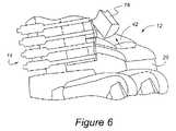
- FIG. 6is similar to FIG. 5 , but shows an occupant of a vehicle impacting a center console having an armrest according to the present invention.
- FIG. 1vehicle occupant 10 is seated upon a seat cushion, 20 .
- Occupant 10has arm 16 , which is poised in FIG. 1 to be placed upon armrest assembly 12 . More precisely, occupant arm 16 is poised to be placed upon arm contact member 42 , which extends generally horizontally at the upper surface of armrest assembly 12 .
- Armrest assembly 12is mounted to a mounting base, which, in the case of FIG. 1 , is door trim panel 22 .
- armrest 12is mounted to a center storage console, 26 .
- Occupant 10has a thoracic region, 14 , which may contact armrest 12 during certain side-directed impact events.
- vehicle door 24is shown as being an impacted by a pendulum type of test device, 28 , which causes deformation of door 24 including trim panel 22 , with the impact ultimately resulting in a contact between thoracic region 14 of occupant 10 and armrest assembly 12 .
- FIGS. 2 and 2 aillustrate the structural attributes of armrest 12 which cause its dynamic deconstruction during an impact event.
- Inner wall 30 and outer wall 34define a cavity, 40 , which, although having a generally rectangular configuration, is frustum-shaped, which gives armrest surface 42 the illustrated plug shape.
- This plug shapecauses a ramping effect when armrest 12 is impacted by a force, (F), directed as shown in FIG. 2 .
- the walls 30 and 34cause the arm contact member 42 to be locally extruded or expelled from cavity 40 . Once, arm contact member 42 has become only slightly misaligned with walls 30 and 34 , the force/deflection curve in the direction F of FIG.
- arm contact surface 42has two portions, 42 a which depend over inner wall 30 and outer wall 34 , as an alternate structure for trimming the interface between arm contact member 42 and walls 30 and 34 .
- cover 46in which may be constructed of plastics, such as vinyl or other materials, is applied over the upper surfaces of armrest 12 in order to conceal the joint between arm contact member 42 and walls 30 and 34 .
- Walls 30 , 34 and arm contact member 42are preferably formed from plastic material such as polypropylene or acrylonitrile butadiene styrene (ABS).
- Contact member 42is preferably a tight, wedge fit within cavity 40 . It is further preferable that member 42 be retained within cavity 40 without the use of adhesives or ultrasonic bonding.
- FIGS. 3-5illustrate the sequential engagement of thoracic region 14 of occupant 10 with armrest 12 during an impact event, accompanied by the deconstruction of armrest 12 .
- arm contact member 42is shown as being dislocated slightly from inner wall 30 and outer wall 34 , while still contacting end wall 38 .
- FIG. 4it is noted that arm contact member 42 has become expelled to a greater degree from cavity 40 and, inner wall 30 has become deformed as well.
- end wall 38 , inner wall 30 , and outer wall 34are all deformed, as is arm contact member 42 , which has become even more dislocated translationally from its original position within cavity 40 .
- FIG. 6occupant 10 is shown as contacting center console 26 , having an armrest 12 according to the present invention. Armrest 12 is shown as during one of the initial stages of deconstruction similar to those illustrated in FIG. 3 . The mechanics of deconstruction of the embodiment shown in FIG. 6 are similar to those illustrated in FIGS. 3-5 .
Landscapes
- Engineering & Computer Science (AREA)
- Aviation & Aerospace Engineering (AREA)
- Transportation (AREA)
- Mechanical Engineering (AREA)
- Vehicle Interior And Exterior Ornaments, Soundproofing, And Insulation (AREA)
- Passenger Equipment (AREA)
- Seats For Vehicles (AREA)
- Body Structure For Vehicles (AREA)
- Vehicle Step Arrangements And Article Storage (AREA)
Abstract
Description
Claims (4)
Priority Applications (3)
| Application Number | Priority Date | Filing Date | Title |
|---|---|---|---|
| US11/308,467US7556301B2 (en) | 2006-03-28 | 2006-03-28 | Dynamically deconstructable armrest for automotive vehicle |
| CN2007100869356ACN101054071B (en) | 2006-03-28 | 2007-03-22 | Dynamically deconstructable armrest for automotive vehicle |
| EP07104718AEP1839939A3 (en) | 2006-03-28 | 2007-03-22 | An armrest assembly for a motor vehicle |
Applications Claiming Priority (1)
| Application Number | Priority Date | Filing Date | Title |
|---|---|---|---|
| US11/308,467US7556301B2 (en) | 2006-03-28 | 2006-03-28 | Dynamically deconstructable armrest for automotive vehicle |
Publications (2)
| Publication Number | Publication Date |
|---|---|
| US20070228757A1 US20070228757A1 (en) | 2007-10-04 |
| US7556301B2true US7556301B2 (en) | 2009-07-07 |
Family
ID=38261677
Family Applications (1)
| Application Number | Title | Priority Date | Filing Date |
|---|---|---|---|
| US11/308,467Expired - Fee RelatedUS7556301B2 (en) | 2006-03-28 | 2006-03-28 | Dynamically deconstructable armrest for automotive vehicle |
Country Status (3)
| Country | Link |
|---|---|
| US (1) | US7556301B2 (en) |
| EP (1) | EP1839939A3 (en) |
| CN (1) | CN101054071B (en) |
Cited By (3)
| Publication number | Priority date | Publication date | Assignee | Title |
|---|---|---|---|---|
| US20080272614A1 (en)* | 2007-05-04 | 2008-11-06 | Ford Global Technologies, Llc | Deformable pull cup arrangement and method of assembly |
| US9233660B1 (en) | 2014-09-24 | 2016-01-12 | Ford Global Technologies, Llc | Armrest assembly including movable core |
| US9238484B2 (en)* | 2014-05-05 | 2016-01-19 | Ford Global Technologies, Llc | Integrated lateral load-transmittal system |
Families Citing this family (2)
| Publication number | Priority date | Publication date | Assignee | Title |
|---|---|---|---|---|
| US9610873B2 (en)* | 2014-04-25 | 2017-04-04 | Ford Global Technologies, Llc | Fully collapsing armrest insert with tunable tensioning elements |
| US10065547B2 (en)* | 2016-09-21 | 2018-09-04 | Ford Global Technologies Llc | Armrest support bridge |
Citations (26)
| Publication number | Priority date | Publication date | Assignee | Title |
|---|---|---|---|---|
| US3428357A (en)* | 1967-12-22 | 1969-02-18 | Arthur M Lueck | Vehicle arm rest |
| US3623768A (en) | 1970-08-05 | 1971-11-30 | Stanford Research Inst | Vehicular safety seat |
| US5395135A (en) | 1992-11-02 | 1995-03-07 | Ford Motor Company | Energy absorbing vehicle door and side panels |
| US5482344A (en) | 1994-12-23 | 1996-01-09 | Ford Motor Company | Deployable vehicle door trim panel |
| US5527084A (en)* | 1995-01-30 | 1996-06-18 | Ceats | Collapsible arm rest, door interior trim panel and arm rest support assembly |
| US5603548A (en) | 1995-10-16 | 1997-02-18 | General Motors Corporation | Push-out vehicle side door |
| US5730458A (en) | 1995-08-18 | 1998-03-24 | Daewoo Electronics Co., Ltd. | Side impact protector with airbag module |
| US5803415A (en)* | 1996-01-11 | 1998-09-08 | Nissan Motor Co., Ltd. | Arm rest device for vehicles |
| US5951094A (en)* | 1995-12-28 | 1999-09-14 | Nissan Motor Co., Ltd. | Arm rest for a vehicle |
| US5967594A (en)* | 1998-05-26 | 1999-10-19 | Ford Global Technologies, Inc. | Vehicle door structure and armrest |
| US6217119B1 (en) | 1999-10-21 | 2001-04-17 | Paccar Inc | Extendable armrest assembly for a seat |
| US6248205B1 (en)* | 1998-09-09 | 2001-06-19 | Leon Plastics, Inc. | Method of fabricating an armrest |
| JP2002046520A (en) | 2000-08-04 | 2002-02-12 | Kasai Kogyo Co Ltd | Armrest for door trim |
| US6568743B1 (en)* | 2002-08-07 | 2003-05-27 | Ford Global Technologies, Inc. | Active armrest for side impact protection |
| DE10211656C1 (en) | 2002-03-15 | 2003-07-17 | Johnson Contr Interiors Gmbh | Interior fitting for a vehicle, e.g. an arm rest, has a carrier structure with hard elasticity bonded to a section of soft elasticity e.g. a foam cushion, where the bonding openings are wholly filled and sealed |
| US6742830B2 (en) | 2001-05-16 | 2004-06-01 | Sai Automotive Sal Gmbh | Shock-absorbent lining element for the interior of a vehicle |
| US20040178660A1 (en)* | 2003-02-19 | 2004-09-16 | Dry Alan G. | Method of forming a vehicle component |
| US6890012B2 (en)* | 2003-06-06 | 2005-05-10 | Seeber Ag & Co. Kg | Foldable cover supported on a bearing |
| US6893077B1 (en)* | 2004-03-18 | 2005-05-17 | Toyota Technical Center Usa, Inc. | Door trim panel having deformable armrest |
| US20050194828A1 (en) | 2003-12-15 | 2005-09-08 | Be Aerospace, Inc. | Vehicle seating with shared armrests |
| US6955391B1 (en) | 2003-01-14 | 2005-10-18 | Ford Global Technologies, Llc | Deployable trim for side impact system in automobiles |
| US6983967B2 (en)* | 2002-08-12 | 2006-01-10 | Leon Plastics, Inc. | Armrest with side impact resistance feature |
| US7070221B2 (en)* | 2004-03-08 | 2006-07-04 | Lear Corporation | Automotive interior trim component with soft feel |
| US7104590B2 (en)* | 2004-07-01 | 2006-09-12 | Lear Corporation | Vehicle trim panel with integral nibbed armrest |
| US7121611B2 (en)* | 2003-07-29 | 2006-10-17 | Mazda Motor Corporation | Armrest structure for vehicle |
| US7144067B2 (en)* | 2003-12-17 | 2006-12-05 | Itw Automotive Products Gmbh & Co. Kg | Arm rest for a door paneling of an automobile |
- 2006
- 2006-03-28USUS11/308,467patent/US7556301B2/ennot_activeExpired - Fee Related
- 2007
- 2007-03-22CNCN2007100869356Apatent/CN101054071B/ennot_activeExpired - Fee Related
- 2007-03-22EPEP07104718Apatent/EP1839939A3/ennot_activeCeased
Patent Citations (27)
| Publication number | Priority date | Publication date | Assignee | Title |
|---|---|---|---|---|
| US3428357A (en)* | 1967-12-22 | 1969-02-18 | Arthur M Lueck | Vehicle arm rest |
| US3623768A (en) | 1970-08-05 | 1971-11-30 | Stanford Research Inst | Vehicular safety seat |
| US5395135A (en) | 1992-11-02 | 1995-03-07 | Ford Motor Company | Energy absorbing vehicle door and side panels |
| US5482344A (en) | 1994-12-23 | 1996-01-09 | Ford Motor Company | Deployable vehicle door trim panel |
| US5527084A (en)* | 1995-01-30 | 1996-06-18 | Ceats | Collapsible arm rest, door interior trim panel and arm rest support assembly |
| US5730458A (en) | 1995-08-18 | 1998-03-24 | Daewoo Electronics Co., Ltd. | Side impact protector with airbag module |
| US5603548A (en) | 1995-10-16 | 1997-02-18 | General Motors Corporation | Push-out vehicle side door |
| US5951094A (en)* | 1995-12-28 | 1999-09-14 | Nissan Motor Co., Ltd. | Arm rest for a vehicle |
| US5803415A (en)* | 1996-01-11 | 1998-09-08 | Nissan Motor Co., Ltd. | Arm rest device for vehicles |
| US5967594A (en)* | 1998-05-26 | 1999-10-19 | Ford Global Technologies, Inc. | Vehicle door structure and armrest |
| US6248205B1 (en)* | 1998-09-09 | 2001-06-19 | Leon Plastics, Inc. | Method of fabricating an armrest |
| US6217119B1 (en) | 1999-10-21 | 2001-04-17 | Paccar Inc | Extendable armrest assembly for a seat |
| JP2002046520A (en) | 2000-08-04 | 2002-02-12 | Kasai Kogyo Co Ltd | Armrest for door trim |
| US6742830B2 (en) | 2001-05-16 | 2004-06-01 | Sai Automotive Sal Gmbh | Shock-absorbent lining element for the interior of a vehicle |
| DE10211656C1 (en) | 2002-03-15 | 2003-07-17 | Johnson Contr Interiors Gmbh | Interior fitting for a vehicle, e.g. an arm rest, has a carrier structure with hard elasticity bonded to a section of soft elasticity e.g. a foam cushion, where the bonding openings are wholly filled and sealed |
| US6568743B1 (en)* | 2002-08-07 | 2003-05-27 | Ford Global Technologies, Inc. | Active armrest for side impact protection |
| US6983967B2 (en)* | 2002-08-12 | 2006-01-10 | Leon Plastics, Inc. | Armrest with side impact resistance feature |
| US6955391B1 (en) | 2003-01-14 | 2005-10-18 | Ford Global Technologies, Llc | Deployable trim for side impact system in automobiles |
| US20040178660A1 (en)* | 2003-02-19 | 2004-09-16 | Dry Alan G. | Method of forming a vehicle component |
| US6899363B2 (en)* | 2003-02-19 | 2005-05-31 | Lear Corporation | Method of forming a vehicle component |
| US6890012B2 (en)* | 2003-06-06 | 2005-05-10 | Seeber Ag & Co. Kg | Foldable cover supported on a bearing |
| US7121611B2 (en)* | 2003-07-29 | 2006-10-17 | Mazda Motor Corporation | Armrest structure for vehicle |
| US20050194828A1 (en) | 2003-12-15 | 2005-09-08 | Be Aerospace, Inc. | Vehicle seating with shared armrests |
| US7144067B2 (en)* | 2003-12-17 | 2006-12-05 | Itw Automotive Products Gmbh & Co. Kg | Arm rest for a door paneling of an automobile |
| US7070221B2 (en)* | 2004-03-08 | 2006-07-04 | Lear Corporation | Automotive interior trim component with soft feel |
| US6893077B1 (en)* | 2004-03-18 | 2005-05-17 | Toyota Technical Center Usa, Inc. | Door trim panel having deformable armrest |
| US7104590B2 (en)* | 2004-07-01 | 2006-09-12 | Lear Corporation | Vehicle trim panel with integral nibbed armrest |
Cited By (6)
| Publication number | Priority date | Publication date | Assignee | Title |
|---|---|---|---|---|
| US20080272614A1 (en)* | 2007-05-04 | 2008-11-06 | Ford Global Technologies, Llc | Deformable pull cup arrangement and method of assembly |
| US7789455B2 (en)* | 2007-05-04 | 2010-09-07 | Ford Global Technologies, Llc | Deformable pull cup arrangement and method of assembly |
| US9238484B2 (en)* | 2014-05-05 | 2016-01-19 | Ford Global Technologies, Llc | Integrated lateral load-transmittal system |
| US20160075219A1 (en)* | 2014-05-05 | 2016-03-17 | Ford Global Technologies, Llc | Integrated lateral load-transmittal system |
| US9676257B2 (en)* | 2014-05-05 | 2017-06-13 | Ford Global Technologies, Llc | Integrated lateral load-transmittal system |
| US9233660B1 (en) | 2014-09-24 | 2016-01-12 | Ford Global Technologies, Llc | Armrest assembly including movable core |
Also Published As
| Publication number | Publication date |
|---|---|
| US20070228757A1 (en) | 2007-10-04 |
| CN101054071B (en) | 2013-05-08 |
| CN101054071A (en) | 2007-10-17 |
| EP1839939A3 (en) | 2009-04-08 |
| EP1839939A2 (en) | 2007-10-03 |
Similar Documents
| Publication | Publication Date | Title |
|---|---|---|
| US7556301B2 (en) | Dynamically deconstructable armrest for automotive vehicle | |
| US8152218B2 (en) | Integral pelvic impact energy-absorbing pre-crush protective construction for vehicle door | |
| US6733064B2 (en) | Impact absorbing assembly for vehicle interior systems and seat backs | |
| US7789455B2 (en) | Deformable pull cup arrangement and method of assembly | |
| CA2514243A1 (en) | Bumper beam with interference-fit energy absorber | |
| US20040262889A1 (en) | Cover and housing structure for an airbag module | |
| JPH10297345A (en) | Automotive footrest | |
| JP2007537091A (en) | Stop support for the front hood of an automobile | |
| JP2001146177A (en) | Assembly structure for cowl louver | |
| JP2000131157A (en) | Pressure sensor | |
| EP0912370B1 (en) | Sound insulating layer with integral rib structure | |
| JP3121950B2 (en) | Clip mounting seat | |
| JPH08276808A (en) | Collision sound generation preventive structure at vehicle's interior trim member butting section and assembling method | |
| JP4793668B2 (en) | Cowl louver assembly structure | |
| JP3997425B2 (en) | Vehicle footrest device | |
| JPH09150699A (en) | Passenger airbag device for automobile | |
| JP2001151160A (en) | Bumper rubber | |
| JP2004175284A (en) | Vehicle side part energy absorption structure | |
| JP3891475B2 (en) | Shock absorbing structure in automotive interior parts | |
| CN212765998U (en) | A blotter and vehicle for vehicle glove box | |
| JP2004034936A (en) | Car interior parts | |
| JPH0530984Y2 (en) | ||
| JPH0731432U (en) | Interior parts for automobiles | |
| JPH07232556A (en) | Interior trim for vehicle | |
| JP2532512Y2 (en) | Car pillar garnish |
Legal Events
| Date | Code | Title | Description |
|---|---|---|---|
| AS | Assignment | Owner name:FORD MOTOR COMPANY, MICHIGAN Free format text:ASSIGNMENT OF ASSIGNORS INTEREST;ASSIGNORS:GOVIND, SHRINIVAS;MARIYAPPA, NAGARAJ;REEL/FRAME:017376/0434;SIGNING DATES FROM 20060308 TO 20060310 | |
| AS | Assignment | Owner name:FORD GLOBAL TECHNOLOGIES, LLC, MICHIGAN Free format text:ASSIGNMENT OF ASSIGNORS INTEREST;ASSIGNOR:FORD MOTOR COMPANY;REEL/FRAME:017408/0517 Effective date:20060403 | |
| FEPP | Fee payment procedure | Free format text:PAYOR NUMBER ASSIGNED (ORIGINAL EVENT CODE: ASPN); ENTITY STATUS OF PATENT OWNER: LARGE ENTITY | |
| STCF | Information on status: patent grant | Free format text:PATENTED CASE | |
| FPAY | Fee payment | Year of fee payment:4 | |
| FPAY | Fee payment | Year of fee payment:8 | |
| FEPP | Fee payment procedure | Free format text:MAINTENANCE FEE REMINDER MAILED (ORIGINAL EVENT CODE: REM.); ENTITY STATUS OF PATENT OWNER: LARGE ENTITY | |
| LAPS | Lapse for failure to pay maintenance fees | Free format text:PATENT EXPIRED FOR FAILURE TO PAY MAINTENANCE FEES (ORIGINAL EVENT CODE: EXP.); ENTITY STATUS OF PATENT OWNER: LARGE ENTITY | |
| STCH | Information on status: patent discontinuation | Free format text:PATENT EXPIRED DUE TO NONPAYMENT OF MAINTENANCE FEES UNDER 37 CFR 1.362 | |
| FP | Lapsed due to failure to pay maintenance fee | Effective date:20210707 |