US7555187B2 - Large effective area fiber - Google Patents
Large effective area fiberDownload PDFInfo
- Publication number
- US7555187B2 US7555187B2US12/151,171US15117108AUS7555187B2US 7555187 B2US7555187 B2US 7555187B2US 15117108 AUS15117108 AUS 15117108AUS 7555187 B2US7555187 B2US 7555187B2
- Authority
- US
- United States
- Prior art keywords
- annular region
- radius
- core
- less
- 3min
- Prior art date
- Legal status (The legal status is an assumption and is not a legal conclusion. Google has not performed a legal analysis and makes no representation as to the accuracy of the status listed.)
- Active
Links
Images
Classifications
- G—PHYSICS
- G02—OPTICS
- G02B—OPTICAL ELEMENTS, SYSTEMS OR APPARATUS
- G02B6/00—Light guides; Structural details of arrangements comprising light guides and other optical elements, e.g. couplings
- G02B6/02—Optical fibres with cladding with or without a coating
- G02B6/036—Optical fibres with cladding with or without a coating core or cladding comprising multiple layers
- G02B6/03616—Optical fibres characterised both by the number of different refractive index layers around the central core segment, i.e. around the innermost high index core layer, and their relative refractive index difference
- G02B6/03638—Optical fibres characterised both by the number of different refractive index layers around the central core segment, i.e. around the innermost high index core layer, and their relative refractive index difference having 3 layers only
- G02B6/0365—Optical fibres characterised both by the number of different refractive index layers around the central core segment, i.e. around the innermost high index core layer, and their relative refractive index difference having 3 layers only arranged - - +
- G—PHYSICS
- G02—OPTICS
- G02B—OPTICAL ELEMENTS, SYSTEMS OR APPARATUS
- G02B6/00—Light guides; Structural details of arrangements comprising light guides and other optical elements, e.g. couplings
- G02B6/02—Optical fibres with cladding with or without a coating
- G02B6/02004—Optical fibres with cladding with or without a coating characterised by the core effective area or mode field radius
- G02B6/02009—Large effective area or mode field radius, e.g. to reduce nonlinear effects in single mode fibres
- G02B6/02014—Effective area greater than 60 square microns in the C band, i.e. 1530-1565 nm
- G02B6/02019—Effective area greater than 90 square microns in the C band, i.e. 1530-1565 nm
Definitions
- the present inventionrelates generally to optical fiber, and particularly optical fibers which have large effective area and low bend loss at 1550 nm.
- Optical amplifier technology and wavelength division multiplexing techniquesare typically required in telecommunication systems that provide high power transmissions for long distances.
- the definition of high power and long distancesis meaningful only in the context of a particular telecommunication system wherein a bit rate, a bit error rate, a multiplexing scheme, and perhaps optical amplifiers are specified.
- high poweris an optical power greater than about 10 mW.
- single power levels of 1 mW or lessare still sensitive to non-linear effects, so that the effective area is still an important consideration in such lower power systems.
- an optical waveguide fiber having a large effective area (A eff )reduces non-linear optical effects, including self-phase modulation, four-wave-mixing, cross-phase modulation, and non-linear scattering processes, all of which can cause degradation of signals in high powered systems.
- an increase in effective area of an optical waveguide fibertypically results in an increase in macrobending induced losses which attenuate signal transmission through a fiber.
- the macrobending lossesbecome increasingly significant over long (e.g., 100 km, or more) distances (or spacing between regenerators, amplifiers, transmitters and/or receivers.
- an optical fibercomprises: a glass core extending from a centerline to a radius R 1 wherein R 1 is greater than about 5 ⁇ m; a glass cladding surrounding and in contact with the core; wherein the core and the cladding provide a fiber with cable cutoff less than 1500 nm, and an effective area at 1550 nm greater than 95 ⁇ m 2 and bend loss of ⁇ 0.7 dB/turn on a 20 mm diameter mandrel.
- the effective area at 1550 nmis greater than 110 ⁇ m 2 and in some embodiments the effective area at 1550 nm is greater than 115 ⁇ m 2 .
- the claddingcontains an annular region of silica based glass with at least 10 (and more preferably at least 50) randomly dispersed closed holes situated therein, and (i) mean distance between the holes is less than 5000 nm, and (ii) at least 80% of the holes have a maximum cross-sectional dimension Di of less than 1000 nm.
- the bend loss at 1550 nmis less than 0.5 dB/turn, less than 0.25 dB/turn, and more preferably less than 0.1 dB/turn, on a 20 mm diameter mandrel. In some exemplary embodiments the bend loss at 1550 nm is less than 0.08 dB/turn, and an in some exemplary embodiments the bend loss than 0.06 dB/turn on a 20 mm diameter mandrel.
- the corecomprises a maximum relative refractive index, ⁇ 1MAX , relative to the third annular region, and wherein ⁇ 1MAX is greater than about 0.1% and less than about 0.3%;
- first annular regionhas a maximum refractive index delta ⁇ 2MAX (r) less than about 0.025% and greater than about ⁇ 0.025%;
- the second annular regioncomprises:
- the core and the claddingprovide a fiber with cable cutoff less than 1500 nm, and an effective area at 1550 nm greater than 110 ⁇ m 2 .
- the optical fiberhas an effective area at 1550 nm greater than 125 ⁇ m 2 .
- the optical fiberhas an effective area at 1550 nm greater than 135 dm 2 .
- the second annular regioncomprises silica glass having a dopant selected from the group consisting of germanium, aluminum, phosphorus, titanium, boron, and fluorine.
- the second annular regioncomprises silica glass with a plurality of closed holes, the holes being either empty (vacuum) or gas filled, wherein the holes provide internal reflection of light, thereby providing wave guiding to light traveling along the core.
- Such holescan provide an effective refractive index which is low, e.g. compared to pure silica.
- the corecomprises a maximum relative refractive index, ⁇ 1MAX , relative to the third annular region, and wherein ⁇ 1MAX is greater than about 0.1% and less than about 0.3%;
- first annular regionhas a maximum refractive index delta ⁇ 2MAX (r) less than about 0.025% and greater than about ⁇ 0.025%;
- the second annular regioncomprises:
- the core and the claddingprovide a fiber with cable cutoff less than 1500 nm, and an effective area at 1550 nm greater than 95 ⁇ m 2 .
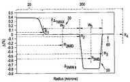
- FIG. 1shows a relative refractive index profile of an embodiment of an optical waveguide fiber as disclosed herein.
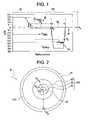
- FIG. 2is a schematic cross-sectional view of an embodiment of an optical waveguide fiber as disclosed herein.
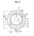
- FIG. 3is a schematic cross-sectional view of another embodiment of an optical waveguide according to the present invention.
- the “refractive index profile”is the relationship between refractive index or relative refractive index and waveguide fiber radius.
- the relative refractive indexis represented by ⁇ and its values are given in units of “%”, unless otherwise specified.
- the relative index percentis negative and is referred to as having a depressed region or depressed index, and the minimum relative refractive index is calculated at the point at which the relative index is most negative unless otherwise specified.
- the refractive index of a regionis greater than the average refractive index of the cladding region, the relative index percent is positive and the region can be said to be raised or to have a positive index.
- An “updopant”is herein considered to be a dopant which has a propensity to raise the refractive index relative to pure undoped SiO 2 .
- a “downdopant”is herein considered to be a dopant which has a propensity to lower the refractive index relative to pure undoped SiO 2 .
- Chromatic dispersionherein referred to as “dispersion” unless otherwise noted, of a waveguide fiber is the sum of the material dispersion, the waveguide dispersion, and the inter-modal dispersion. In the case of single mode waveguide fibers the inter-modal dispersion is zero. Dispersion slope is the rate of change of dispersion with respect to wavelength.
- effective areaor “A eff ” refers to optical effective area at a wavelength of 1550 nm unless otherwise noted.
- the bend resistance of a waveguide fibercan be gauged by induced attenuation under prescribed test conditions, for example by deploying or wrapping the fiber around a mandrel of a prescribed diameter.
- the theoretical fiber cutoff wavelength, or “theoretical fiber cutoff”, or “theoretical cutoff”, for a given mode,is the wavelength above which guided light cannot propagate in that mode.
- a mathematical definitioncan be found in Single Mode Fiber Optics, Jeun Subscribe, pp. 39-44, Marcel Dekker, New York, 1990 wherein the theoretical fiber cutoff is described as the wavelength at which the mode propagation constant becomes equal to the plane wave propagation constant in the outer cladding. This theoretical wavelength is appropriate for an infinitely long, perfectly straight fiber that has no diameter variations.
- the actual fiber cutoffcan be measured by the standard 2 m fiber cutoff test, FOTP-80 (EIA-TIA-455-80), to yield the “fiber cutoff wavelength”, also known as the “2 m fiber cutoff” or “measured cutoff”.
- FOTP-80standard test is performed to either strip out the higher order modes using a controlled amount of bending, or to normalize the spectral response of the fiber to that of a multimode fiber.
- the cabled cutoff wavelength, or “cabled cutoff”is even lower than the measured fiber cutoff due to higher levels of bending and mechanical pressure in the cable environment.
- the actual cabled conditioncan be approximated by the cabled cutoff test described in the EIA-445 Fiber Optic Test Procedures, which are part of the EIA-TIA Fiber Optics Standards, that is, the Electronics Industry Alliance-Telecommunications Industry Association Fiber Optics Standards, more commonly known as FOTP's. Cabled cutoff measurement is described in EIA-455-170 Cable Cutoff Wavelength of Single-mode Fiber by Transmitted Power, or “FOTP-170”. By cable cutoff as used herein, we mean the value obtained using the approximated test.
- optical properties(such as dispersion, dispersion slope, etc.) are reported for the LP01 mode. Unless otherwise noted herein, a wavelength of 1550 nm is the reference wavelength.
- the optical fiber 10 disclosed hereincomprises a core 20 and a cladding layer (or cladding) 200 surrounding and directly adjacent the core.
- the core 20has a refractive index profile, ⁇ Core (r).
- the cladding 200has a refractive index profile, ⁇ CLAD (r).
- the cladding 200comprises a region of pure silica surrounded by region containing random air holes situated within Si based glass.
- the corecomprises silica doped with germanium, i.e. germania doped silica.
- Dopants other than germanium, singly or in combination,may be employed within the core, and particularly at or near the centerline, of the optical fiber disclosed herein to obtain the desired refractive index and density.
- the refractive index profile of the optical fiber 10 disclosed hereinis non-negative from the centerline to the inner radius R 2 of the annular region 30 .
- the optical fiber 10contains no index-decreasing dopants in the core 20 .
- optical waveguide fibers 10comprise: a core 20 extending radially outwardly from the centerline to a central segment outer radius, R 1 (preferably >5 ⁇ m), and having a relative refractive index profile, ⁇ 1 (r) in %, with a maximum relative refractive index percent, ⁇ 1MAX (preferably ⁇ 0.3% and greater than 0.1%); and, a cladding 200 surrounding and directly adjacent, i.e. in direct contact with, the core 20 .
- R 1is defined to occur at the radius where ⁇ 1 (r) first reaches +0.05%. That is, core 20 ends and the annular region 30 starts where the relative refractive index first reaches +0.05% (going outward radially) at a radius R 1 , and region 30 is defined to end at a radius R 2 where the relative refractive index ⁇ 2 (r) first reaches ⁇ 0.05%, going outward radially.
- the second annular region 50begins at R 2 and ends at R 3 for this group of embodiments.
- R 3is defined to occur where the relative refractive index ⁇ 3 (r) reaches the value of ⁇ 0.05% (going outward radially), after ⁇ 3 (r) has dipped to at least ⁇ 0.05%.
- the width W 3 of the second annular region 50is R 3 ⁇ R 2 and its midpoint is R 3MID is (R 2 +R 3 )/2.
- more than 90% of the core 20has a positive relative refractive index, and in some embodiments ⁇ 1 (r) is positive for all radii from 0 to R 1 .
- ⁇ 3 (r)is negative for all radii from R 2 to R 3 .
- ⁇ CLAD (r)0% for all radii greater than 30 ⁇ m.
- Cladding 200extends to a radius, R 4 , which is also the outermost periphery of the glass part of the optical fiber. Also, ⁇ 1MAX > ⁇ 2MAX > ⁇ 3MIN , and ⁇ 2MIN > ⁇ 3MIN .
- the second annular region 50comprises silica glass having at least one dopant selected from the group consisting of germanium, aluminum, phosphorus, titanium, boron, and fluorine.
- the second annular region 50comprises silica based glass (either pure silica, or silica doped with for example, germanium, aluminum, phosphorus, titanium, boron, and fluorine) with a plurality of closed randomly dispersed holes 16 A, the holes 16 A being either empty (vacuum) or gas (e.g. argon, or air) filled.
- Such holescan provide an effective refractive index which is low, e.g. compared to pure silica.
- the fiber core region 20(with a step index, n 1 ,) is surrounded by the first annular region 30 (with an index, n 2 ), which is situated adjacent to and is surrounded by the second annular region 50 having radial width, w 3 , which is further surrounded by a third annular region 60 (with an index, n 4 , and a radial width, w 4 ), which can optionally be surrounded by one or more polymer coatings 65 .
- the relative percent index of refraction ( ⁇ n %) in second annular region 50fluctuates between ⁇ 28% (index of void filled gas relative to that of silica) and that of the glass surrounding the holes (in this example it is silica, with the relative % index of refraction ⁇ n 5 of about 0%).
- a typical average relative refractive index percent ⁇ n ave of the second annular region 50will be between ⁇ 2% and ⁇ 3%, relative to pure silica glass, depending on the dopants present in the glass surrounding the holes. That is, the index second annular region 50 fluctuates, and in the example of FIG. 3 , the width of the gas filled holes, and/or the glass filled spacing S v between the gas filled holes is randomly distributed and/or are not equal to one another.
- the holesare non-periodic. It is preferable that the mean distance between the holes is less than 5000 nm, more preferably less than 2000 nm, even more preferably less than 1000 nm, for example 750 nm, 500 nm, 400 nm, 300 nm, 200 nm or 100 nm. Preferably, at least 80%, and more preferably at least 90% of the holes have a maximum cross-sectional dimension Di of less than 1000 nm, preferably less than 500 nm. Even more preferably, the mean diameter of the holes is less than 1000 nm, more preferably less than 500 nm, and even more preferably less than 300 nm.
- the holes 16 Aare closed (surrounded by solid material) and are non-periodic. That is, the holes 16 A may have the same size, or may be of different sizes. The distances between holes may be uniform (i.e., the same), or may be different.
- the second annular region 50contains at least 10 holes, more preferably at least 50 holes, even more preferably at least 100 holes and most preferably at least 200 holes.
- the core 20has a profile volume, V 1 , defined herein as:
- the second annular region 50has a profile volume, V 3 , defined herein as:
- ,is greater than 20%- ⁇ m 2 .
- ⁇ 0.5%we mean ⁇ is more negative than ⁇ 0.5%.
- W 2>2 ⁇ 3R 1 , in some embodiments W 2 >R 1 , and in some embodiments, W 2 >2R 1 . In some embodiments W 2 >5 ⁇ m.
- W 2may be at least: 5.5 ⁇ m, 8 ⁇ m, or even greater than 10 ⁇ m. Preferably, 10 ⁇ m ⁇ W 2 ⁇ 16 ⁇ m.
- R 2>8 ⁇ m, more preferably >12 ⁇ m and, in some embodiments, equal to or greater than about 15.0 ⁇ m, for example R 2 ⁇ 20 ⁇ m.
- W 2is between about 3 ⁇ m and 18 ⁇ m, and in some embodiments, W 2 is between about 7 ⁇ m and 15 ⁇ m.
- R 3>11.0 ⁇ m, and in some embodiments 11.5 ⁇ m ⁇ R 3 ⁇ 30.0 ⁇ m, for example, R 3 is about 12 ⁇ m, 13 ⁇ m, 15 ⁇ m or 20 ⁇ m.
- W 3>1.0 ⁇ m, in some embodiments W 3 >2.0 ⁇ m, for example 2.0 ⁇ W 3 ⁇ 10.0 ⁇ m. In some embodiments W 3 is less than 6.0 ⁇ m, and in some embodiments 3.0 ⁇ W 3 ⁇ 9.0 ⁇ m, and in some embodiments 3.0 ⁇ W 3 ⁇ 7.0 ⁇ m. Also in some embodiments, ⁇ 3MIN is less than ⁇ 0.35%, and in some other embodiments, less than ⁇ 0.5%.
- R 4>50 ⁇ m. In some embodiments, R 4 ⁇ 55 ⁇ m. In other embodiments, R 4 ⁇ 60 ⁇ m. In some embodiments, 60 ⁇ m ⁇ R 4 ⁇ 90 ⁇ m. For example, R 4 may be 62.5 ⁇ m, 70 ⁇ m, 75 ⁇ m, 80 ⁇ m, or 85 ⁇ m.
- the central segment of the core 20may comprise a relative refractive index profile having a so-called centerline dip which may occur as a result of one or more optical fiber manufacturing techniques.
- the optical fiber disclosed hereinprovides: a mode field diameter at 1550 nm is greater than 11 ⁇ m, and in some embodiments, between 11 ⁇ m and 15 ⁇ m, more preferably between 12.5 ⁇ m and 14.5 ⁇ m.
- the effective area at 1550 nmis greater than 110 ⁇ m 2 , more preferably greater than 115 ⁇ m 2 , more preferably greater than 125 ⁇ m 2 , even more preferably greater than 135 ⁇ m 2 , and in some embodiments greater than 145 ⁇ m 2 .
- Tables 1-2list characteristics of illustrative examples 1-7.
- the refractive index profiles of Examples 1-7are similar to the fibers of FIGS. 1-3 , with the following respective values. Note that in these examples ⁇ 2 % is about 0.0 (silica).
- the exemplary optical fibershave effective area (Aeff) of 95 ⁇ m 2 to 180 ⁇ m 2 (at 1550 nm) and/or MFD between about 11 ⁇ m and 15 ⁇ m. These fibers also have chromatic dispersion values between about 17 ps/nm/km and about 21 ps/nm/km at 1550 nm, and dispersion slope between 0.05 ps/nm 2 /km and 0.07 ps/nm 2 /km.
- the kappa value, defined as the ratio of the dispersion to the dispersion slope,is preferably between 290 and 330 nm, more preferably between 300 and 320 nm.
- the optical effective areais over 110 ⁇ m 2 and in other embodiments greater than 120 ⁇ m 2 .
- a few exemplary fibershave been shown in Table 1 and Table 2, with their profile parameters specified in Table 1 and optical properties shown in Table 2. They have effective areas between about 110 ⁇ m 2 and 155 ⁇ m 2 at 1550 nm and MFDs between 11.4 ⁇ m and 14.2 ⁇ m and dispersion slopes between 0.06 ps/nm 2 /km and 0.065 ps/nm 2 /km.
- One advantage of the designis that the cable cutoff wavelength for the core is preferably lower than 1450 nm, more preferably lower than 1400 nm, even more preferably lower than 1350 nm.
- the bending lossesmay be minimized by choosing: (i) the proper location of the second annular region and (ii) proper values of the volume of the second annular region 50 , which volume is defined as the product of the cross sectional area of the second annular region's sectional area and the absolute value of delta ⁇ 3min in percent.
- the volume of the second annular region 50affects actual the fiber and cable cutoff wavelengths. To have a cable cutoff wavelength less than 1500 nm, it is preferable that the absolute value of the volume
- the cable cutoff wavelengthmay be greater than the theoretical cutoff or even longer than 1550 nm.
- the theoretical cutoff wavelength for the coreis below 1500 nm, this kind of fiber can be still used in the single mode fiber systems operating in the 1550 nm window by using a standard single mode fiber launching and receiving technique to ensure single mode operation.
- second annular region 50can be formed either by down doping (e.g. by use of Fluorine dopant) or by having a plurality of gas filed holes (e.g. air filled holes) imbedded in the second annular fiber region 50 .
- the bending performance calculated in Table 2is based on the use of the effective refractive index in the second annular region. Therefore, bending properties are applicable to both types of optical fiber (i.e., fiber that is Fluorine doped, or that has air holes in the region 50 ). Bending performance is an important property of optical fibers. In a conventional large area fiber (with Aeff greater than about 95 ⁇ m 2 or larger) the bending performance degrades dramatically as the optical effective area increases.
- optical fibers according to the embodiments of present inventionexhibit very small bend loss even when their effective areas exceed 100 ⁇ m 2 , or 110 ⁇ m 2 , 112 ⁇ m 2 , 115 ⁇ m 2 or more.
- Optical fibers according to the present inventionfor example fibers disclosed in Table 1 and 2, exhibit superior bend loss resistance, both in terms of macrobend and macrobend in a level comparable or better than conventional fibers with known and acceptable bending performance such as SMF-28e®.
- the bending losses of the measured reference SMF-28e® fiber at 1550 nmare 2.9 dB/turn at 15 mm bending diameter, 0.58 dB/turn at 20 mm bending diameter and 0.02 dB/turn at 30 mm bending diameter.
- the SMF-28e® fiberhas an effective area of about 83 ⁇ m 2 .
- optical fiber of the present invention optical fiberhave bending losses at 1550 nm of no more than 0.7 dB/turn, preferably no more than 0.50 dB/turn and preferably less than 0.4 dB/turn and even more preferably less than 0.35 dB/turn at 20 mm bending diameter; and/or less than 0.01 dB/turn at 30 mm bending diameter.
- optical fiber of the present invention optical fiberhave bending losses at 1550 nm of no greater than about 0.25 dB/turn, preferably less than 0.20 dB/turn, more preferably less than 0.1 dB/turn, at 20 mm bending diameter, and/or no greater than 0.008 dB/turn at 30 mm bending diameter.
- optical fiber of the present invention optical fiberhave bending losses at 1550 nm of no greater than about 0.05 and preferably less than 0.03 dB/turn at 20 mm bending diameter and/or no greater than 0.006 dB/turn at 30 mm bending diameter. Some embodiments of the optical fiber of the present invention optical fiber have bending losses at 1550 nm of no greater than about 0.01 dB/turn at 20 mm bending diameter and/or no greater than 0.003 dB/turn at 30 mm bending diameter.
- the bending performancecan be also optimized by changing the location and the volume of the second annular region 50 .
- fiber 3(Tables 1 and 2) has better bending performance than reference fiber SMF-28e® at 20 mm bending diameter at 1550 nm and worse bending performance at 30 mm bending diameter at 1550 nm.
- fiber 4Tables 1 and 2
- the improvement of the bending performance in fiber 4 over fiber 3is due to both the more optimized location of the second annular region, (further away from the core), and the larger absolute volume of the second annular region.
- Moving the second annular region closer to the center of the corecan have the effect of increasing the dispersion and slope.
- the choice of the location of the second annular region 50is influenced by a few factors, including the fiber dispersion, dispersion slope and the bending performance (i.e., low bend induced loss).
- the parameters of second annular region 50are chosen to yield satisfactory bending performance.
- bending induced lossis minimized by increasing the volume of the second annular region 50 .
- Tables 1 and Table 2demonstrate that the increase the volume of the second annular region improves bending performance (i.e., lowers bend induced losses). More specifically, Table 2 shows that even fibers with much larger optical effective area than SMF-28e® (e.g., fibers 5, 6 and 7) have better bending performance than SMF-28e® fiber (which has a much smaller optical effective area at 1550 nm). However, when the volume of the second annular region is too large, it may trap light inside, making the fiber multimoded. In this case, because the core is still single moded, we can still use a single mode launch technique to ensure single mode operation.
- SMF-28e®e.g., fibers 5, 6 and 7
- single mode launch techniquewe mean that the optical signal is launched into the transmission fiber through a standard single mode fiber and another single mode fiber is used to couple of the output end of the transmission fiber to the receiver.
- the standard single mode and transmission fibersare sufficiently well-aligned to yield splice losses less than 0.5 dB, more preferably less than 0.3 dB.
- the second annular section of Fiber 8is comprised of silica glass doped with fluorine and has minimum relative refractive index of ⁇ 0.47 with respect to the silica outer cladding.
- the second annular section of Fiber 9is comprised of silica glass with a plurality of closed holes filled with Argon gas. Fiber 8 and Fiber 9 have rounded step index core with maximum refractive indices of 0.19 and 0.28%, respectively.
- the profile volume of the core, V 1is greater than 5.0%- ⁇ m 2 and less than 9.0%- ⁇ m 2 , and in some embodiments, V 1 is between 6.50%- ⁇ m 2 and 7.5%- ⁇ m 2 .
- the core 20 of the optical fiber 10 shown in FIGS. 1 , 2 and 3has a refractive index profile having either a step shape, or a rounded step shape or an alpha shape with the alpha taking a finite value.
- the core 20could have other values of ⁇ 1 , or the core could have a profile shape other than an alpha profile, such as a multi-segmented core.
- the optical fibers disclosed hereinhave low water content, and preferably are low water peak optical fibers, i.e. having an attenuation curve which exhibits a relatively low, or no, water peak in a particular wavelength region, especially in the E-band.
Landscapes
- Physics & Mathematics (AREA)
- General Physics & Mathematics (AREA)
- Optics & Photonics (AREA)
- Optical Fibers, Optical Fiber Cores, And Optical Fiber Bundles (AREA)
- Glass Compositions (AREA)
Abstract
Description
This application claims the benefit of U.S. Provisional Application No. 60/927,989 filed May 7, 2007, entitled “Large Effective Area Fiber”.
1. Field of the Invention
The present invention relates generally to optical fiber, and particularly optical fibers which have large effective area and low bend loss at 1550 nm.
2. Technical Background
Optical amplifier technology and wavelength division multiplexing techniques are typically required in telecommunication systems that provide high power transmissions for long distances. The definition of high power and long distances is meaningful only in the context of a particular telecommunication system wherein a bit rate, a bit error rate, a multiplexing scheme, and perhaps optical amplifiers are specified. There are additional factors, known to those skilled in the art, which have impacted upon the definition of high power and long distance. However, for most purposes, high power is an optical power greater than about 10 mW. In some applications, single power levels of 1 mW or less are still sensitive to non-linear effects, so that the effective area is still an important consideration in such lower power systems.
Generally, an optical waveguide fiber having a large effective area (Aeff) reduces non-linear optical effects, including self-phase modulation, four-wave-mixing, cross-phase modulation, and non-linear scattering processes, all of which can cause degradation of signals in high powered systems.
On the other hand, an increase in effective area of an optical waveguide fiber typically results in an increase in macrobending induced losses which attenuate signal transmission through a fiber. The macrobending losses become increasingly significant over long (e.g., 100 km, or more) distances (or spacing between regenerators, amplifiers, transmitters and/or receivers. Unfortunately, the larger the effective area of a conventional optical fiber is, the higher the macrobend induced losses tend to be.
Communication systems which typically require one gigabyte per second, and higher, transmission rates, together with regenerators spacing in excess of 100 km, typically make use of optical amplifier technology and/or wavelength division multiplexing techniques. Thus, waveguide fiber manufacturers have designed waveguides which are less susceptible to non-linear effects induced by higher power signals or by four wave mixing, which can occur in multiplexing systems.
According to one aspect of the present invention an optical fiber comprises: a glass core extending from a centerline to a radius R1wherein R1is greater than about 5 μm; a glass cladding surrounding and in contact with the core; wherein the core and the cladding provide a fiber with cable cutoff less than 1500 nm, and an effective area at 1550 nm greater than 95 μm2and bend loss of ≦0.7 dB/turn on a 20 mm diameter mandrel. In some embodiments the effective area at 1550 nm is greater than 110 μm2and in some embodiments the effective area at 1550 nm is greater than 115 μm2. Preferably the cladding contains an annular region of silica based glass with at least 10 (and more preferably at least 50) randomly dispersed closed holes situated therein, and (i) mean distance between the holes is less than 5000 nm, and (ii) at least 80% of the holes have a maximum cross-sectional dimension Di of less than 1000 nm. Preferably the bend loss at 1550 nm is less than 0.5 dB/turn, less than 0.25 dB/turn, and more preferably less than 0.1 dB/turn, on a 20 mm diameter mandrel. In some exemplary embodiments the bend loss at 1550 nm is less than 0.08 dB/turn, and an in some exemplary embodiments the bend loss than 0.06 dB/turn on a 20 mm diameter mandrel.
According to one exemplary embodiment of the present invention an optical fiber comprises:
- a glass core extending from a centerline to a radius R1wherein R1is greater than about 5 μm;
- a glass cladding surrounding and in contact with the core, the cladding comprising: (i) a first annular region extending from the radius R1to a radius R2, the first annular region comprising a radial width, W2=R2−R1, (ii) a second annular region extending from the radius R2to a radius R3, and comprising a radial width, W3=R3−R2, and (iii) a third annular region surrounding the second annular region and extending from the radius R3to an outermost glass radius R4;
wherein the core comprises a maximum relative refractive index, Δ1MAX, relative to the third annular region, and wherein Δ1MAXis greater than about 0.1% and less than about 0.3%;
wherein the first annular region has a maximum refractive index delta Δ2MAX(r) less than about 0.025% and greater than about −0.025%;
wherein the second annular region comprises:
- a minimum relative refractive index, Δ3MIN, relative to the third annular region;
wherein Δ1MAX>Δ2MAX>Δ3MIN, and Δ3MIN<0; and
wherein the core and the cladding provide a fiber with cable cutoff less than 1500 nm, and an effective area at 1550 nm greater than 110 μm2. In some exemplary embodiments the optical fiber has an effective area at 1550 nm greater than 125 μm2. In some exemplary embodiments the optical fiber has an effective area at 1550 nm greater than 135 dm2.
In one set of embodiments, the second annular region comprises silica glass having a dopant selected from the group consisting of germanium, aluminum, phosphorus, titanium, boron, and fluorine.
In another set of embodiments, the second annular region comprises silica glass with a plurality of closed holes, the holes being either empty (vacuum) or gas filled, wherein the holes provide internal reflection of light, thereby providing wave guiding to light traveling along the core. Such holes can provide an effective refractive index which is low, e.g. compared to pure silica.
According to one exemplary embodiment an optical fiber comprises:
a glass core extending from a centerline to a radius R1wherein R1is greater than about 5 μm and a glass cladding surrounding and in contact with the core, the cladding comprising: (i) a first annular region extending from R1to a radius R2, the first annular region comprising a radial width, W2=R2−R1, (ii) a second annular region extending from R2to a radius R3, and comprising a radial width, W3=R3−R2, and (iii) a third annular region surrounding the second annular region and extending from the radius R3to an outermost glass radius R4;
wherein the core comprises a maximum relative refractive index, Δ1MAX, relative to the third annular region, and wherein Δ1MAXis greater than about 0.1% and less than about 0.3%;
wherein the first annular region has a maximum refractive index delta Δ2MAX(r) less than about 0.025% and greater than about −0.025%;
wherein the second annular region comprises:
- a minimum relative refractive index, Δ3MIN, relative to the third annular region; wherein Δ1MAX>Δ2MAX>Δ3MIN, and Δ3MIN<0, and includes silica based glass with at least 10 randomly dispersed closed holes situated therein, and (i) mean distance between the holes is less than 5000 nm, and (ii) at least 80% of the holes have a maximum cross-sectional dimension Di of less than 1000 nm; and
wherein the core and the cladding provide a fiber with cable cutoff less than 1500 nm, and an effective area at 1550 nm greater than 95 μm2.
Reference will now be made in detail to the present preferred embodiments of the invention, examples of which are illustrated in the accompanying drawings.
Additional features and advantages of the invention will be set forth in the detailed description which follows and will be apparent to those skilled in the art from the description or recognized by practicing the invention as described in the following description together with the claims and appended drawings.
The “refractive index profile” is the relationship between refractive index or relative refractive index and waveguide fiber radius.
The “relative refractive index percent” is defined as Δ %=100×(ni2−nc2)/2ni2, where niis the maximum refractive index in region i, unless otherwise specified, and ncis the average refractive index of the third annular region60 (outer region) of the cladding. As used herein, the relative refractive index is represented by Δ and its values are given in units of “%”, unless otherwise specified. In cases where the refractive index of a region is less than the average refractive index of the thirdannular region 60, the relative index percent is negative and is referred to as having a depressed region or depressed index, and the minimum relative refractive index is calculated at the point at which the relative index is most negative unless otherwise specified. In cases where the refractive index of a region is greater than the average refractive index of the cladding region, the relative index percent is positive and the region can be said to be raised or to have a positive index. An “updopant” is herein considered to be a dopant which has a propensity to raise the refractive index relative to pure undoped SiO2. A “downdopant” is herein considered to be a dopant which has a propensity to lower the refractive index relative to pure undoped SiO2.
“Chromatic dispersion”, herein referred to as “dispersion” unless otherwise noted, of a waveguide fiber is the sum of the material dispersion, the waveguide dispersion, and the inter-modal dispersion. In the case of single mode waveguide fibers the inter-modal dispersion is zero. Dispersion slope is the rate of change of dispersion with respect to wavelength.
“Effective area” is defined as:
Aeff=2π(∫f2r dr)2/(∫f4r dr),
where the integration limits are 0 to ∞, and f is the transverse component of the electric field associated with light propagated in the waveguide. As used herein, “effective area” or “Aeff” refers to optical effective area at a wavelength of 1550 nm unless otherwise noted.
The term “α-profile” or “alpha profile” refers to a relative refractive index profile, expressed in terms of Δ(r) which is in units of “%”, where r is radius, which follows the equation,
Δ(r)=Δ(r0)(1−[|r−r0|/(r1−r0)]α),
where r0is the point at which Δ(r) is maximum, r1is the point at which Δ(r) % is zero, and r is in the range ri≦r≦rf, where Δ is defined above, riis the initial point of the α-profile, rfis the final point of the α-profile, and α is an exponent which is a real number.
The mode field diameter (MFD) is measured using the Peterman II method wherein, 2w=MFD, and w2=(2∫f2r dr/∫[df/dr]2r dr), the integral limits being 0 to ∞.
The bend resistance of a waveguide fiber can be gauged by induced attenuation under prescribed test conditions, for example by deploying or wrapping the fiber around a mandrel of a prescribed diameter.
The theoretical fiber cutoff wavelength, or “theoretical fiber cutoff”, or “theoretical cutoff”, for a given mode, is the wavelength above which guided light cannot propagate in that mode. A mathematical definition can be found in Single Mode Fiber Optics, Jeunhomme, pp. 39-44, Marcel Dekker, New York, 1990 wherein the theoretical fiber cutoff is described as the wavelength at which the mode propagation constant becomes equal to the plane wave propagation constant in the outer cladding. This theoretical wavelength is appropriate for an infinitely long, perfectly straight fiber that has no diameter variations.
The actual fiber cutoff can be measured by the standard 2 m fiber cutoff test, FOTP-80 (EIA-TIA-455-80), to yield the “fiber cutoff wavelength”, also known as the “2 m fiber cutoff” or “measured cutoff”. The FOTP-80 standard test is performed to either strip out the higher order modes using a controlled amount of bending, or to normalize the spectral response of the fiber to that of a multimode fiber.
The cabled cutoff wavelength, or “cabled cutoff” is even lower than the measured fiber cutoff due to higher levels of bending and mechanical pressure in the cable environment. The actual cabled condition can be approximated by the cabled cutoff test described in the EIA-445 Fiber Optic Test Procedures, which are part of the EIA-TIA Fiber Optics Standards, that is, the Electronics Industry Alliance-Telecommunications Industry Association Fiber Optics Standards, more commonly known as FOTP's. Cabled cutoff measurement is described in EIA-455-170 Cable Cutoff Wavelength of Single-mode Fiber by Transmitted Power, or “FOTP-170”. By cable cutoff as used herein, we mean the value obtained using the approximated test.
Unless otherwise noted herein, optical properties (such as dispersion, dispersion slope, etc.) are reported for the LP01 mode. Unless otherwise noted herein, a wavelength of 1550 nm is the reference wavelength.
Referring toFIGS. 1-3 , theoptical fiber 10 disclosed herein comprises acore 20 and a cladding layer (or cladding)200 surrounding and directly adjacent the core. Thecore 20 has a refractive index profile, ΔCore(r). Thecladding 200 has a refractive index profile, ΔCLAD(r). In some embodiments, thecladding 200 comprises a region of pure silica surrounded by region containing random air holes situated within Si based glass.
In some embodiments, the core comprises silica doped with germanium, i.e. germania doped silica. Dopants other than germanium, singly or in combination, may be employed within the core, and particularly at or near the centerline, of the optical fiber disclosed herein to obtain the desired refractive index and density.
In some embodiments, the refractive index profile of theoptical fiber 10 disclosed herein is non-negative from the centerline to the inner radius R2of theannular region 30. In some embodiments, theoptical fiber 10 contains no index-decreasing dopants in thecore 20.
Referring toFIGS. 1 and 2 optical waveguide fibers 10 are disclosed herein which comprise: a core20 extending radially outwardly from the centerline to a central segment outer radius, R1(preferably >5 μm), and having a relative refractive index profile, Δ1(r) in %, with a maximum relative refractive index percent, Δ1MAX(preferably ≦0.3% and greater than 0.1%); and, acladding 200 surrounding and directly adjacent, i.e. in direct contact with, thecore 20. Cladding200 comprises: a firstannular region 30 surrounding thecore 20 and directly adjacent thereto, extending radially outwardly to a secondannular region 50 and characterized by radius R2, thisregion 30 having a width W2(W2=R2−R1), and a relative refractive index profile, Δ2(r) in %, with a maximum relative refractive index percent, Δ2MAX, in % (where Δ2MAXis preferably less than about 0.025% and preferably greater than about −0.025%), a minimum relative refractive index percent, Δ2MIN, in %; a secondannular region 50surrounding region 30 and directly adjacent thereto, and extending radially outwardly from R2to an radius R3, theregion 50 having a width W3, and having a relative refractive index profile, Δ3(r) in percent (%), with a minimum relative refractive index percent, Δ3MIN, in % (preferably Δ3MIN≦−0.3%), wherein Δ1MAX>0>Δ3MIN; and a thirdannular region 60 surrounding theregion 50 and directly adjacent thereto and having a relative refractive index percent, Δ4(r) in %. R1is defined to occur at the radius where Δ1(r) first reaches +0.05%. That is,core 20 ends and theannular region 30 starts where the relative refractive index first reaches +0.05% (going outward radially) at a radius R1, andregion 30 is defined to end at a radius R2where the relative refractive index Δ2(r) first reaches −0.05%, going outward radially. The secondannular region 50 begins at R2and ends at R3for this group of embodiments. R3is defined to occur where the relative refractive index Δ3(r) reaches the value of −0.05% (going outward radially), after Δ3(r) has dipped to at least −0.05%. The width W3of the secondannular region 50 is R3−R2and its midpoint is R3MIDis (R2+R3)/2. In some embodiments, more than 90% of thecore 20 has a positive relative refractive index, and in some embodiments Δ1(r) is positive for all radii from 0 to R1. In some embodiments, |Δ2(r)|<0.025% and |Δ2max−Δ2min|<0.05% for more than 50% of the radial width of the firstannular region 30, and in other embodiments |Δ2(r)|<0.01% for more than 50% of the radial width of the firstannular region 30. Δ3(r) is negative for all radii from R2to R3. Preferably, ΔCLAD(r)=0% for all radii greater than 30 μm. Cladding200 extends to a radius, R4, which is also the outermost periphery of the glass part of the optical fiber. Also, Δ1MAX>Δ2MAX>Δ3MIN, and Δ2MIN>Δ3MIN.
In one set of embodiments, depicted inFIGS. 1 and 2 , the secondannular region 50 comprises silica glass having at least one dopant selected from the group consisting of germanium, aluminum, phosphorus, titanium, boron, and fluorine. In another set of embodimentsFIG. 3 ), the secondannular region 50 comprises silica based glass (either pure silica, or silica doped with for example, germanium, aluminum, phosphorus, titanium, boron, and fluorine) with a plurality of closed randomly dispersed holes16A, the holes16A being either empty (vacuum) or gas (e.g. argon, or air) filled. Such holes can provide an effective refractive index which is low, e.g. compared to pure silica.
More specifically, referring toFIG. 3 , the fiber core region20 (with a step index, n1,) is surrounded by the first annular region30 (with an index, n2), which is situated adjacent to and is surrounded by the secondannular region 50 having radial width, w3, which is further surrounded by a third annular region60 (with an index, n4, and a radial width, w4), which can optionally be surrounded by one ormore polymer coatings 65. The relative percent index of refraction (Δn %) in secondannular region 50 fluctuates between −28% (index of void filled gas relative to that of silica) and that of the glass surrounding the holes (in this example it is silica, with the relative % index of refraction Δn5of about 0%). A typical average relative refractive index percent Δnaveof the secondannular region 50 will be between −2% and −3%, relative to pure silica glass, depending on the dopants present in the glass surrounding the holes. That is, the index secondannular region 50 fluctuates, and in the example ofFIG. 3 , the width of the gas filled holes, and/or the glass filled spacing Svbetween the gas filled holes is randomly distributed and/or are not equal to one another. That is, the holes are non-periodic. It is preferable that the mean distance between the holes is less than 5000 nm, more preferably less than 2000 nm, even more preferably less than 1000 nm, for example 750 nm, 500 nm, 400 nm, 300 nm, 200 nm or 100 nm. Preferably, at least 80%, and more preferably at least 90% of the holes have a maximum cross-sectional dimension Di of less than 1000 nm, preferably less than 500 nm. Even more preferably, the mean diameter of the holes is less than 1000 nm, more preferably less than 500 nm, and even more preferably less than 300 nm. The holes16A are closed (surrounded by solid material) and are non-periodic. That is, the holes16A may have the same size, or may be of different sizes. The distances between holes may be uniform (i.e., the same), or may be different. Preferably the secondannular region 50 contains at least 10 holes, more preferably at least 50 holes, even more preferably at least 100 holes and most preferably at least 200 holes.
Thecore 20 has a profile volume, V1, defined herein as:
The secondannular region 50 has a profile volume, V3, defined herein as:
Preferably, Δ1MAX<0.3%, Δ2MIN>−0.05%, Δ2MAX<0.05%, Δ3MIN<−0.3%, 0.1<R1/R2<0.6, and the absolute magnitude of the profile volume of the second annular region, |V3|, is greater than 20%-μm2. Preferably, Δ3MIN<−0.3%, More preferably, Δ3MIN<−0.45%, and even more preferably ≦−0.7%. When we say, for example, Δ<−0.5%, we mean Δ is more negative than −0.5%. Preferably 0.15<R1/R2<0.5. In some embodiments, 0.2<R1/R2≦0.4, for example R1/R2=0.25, 0.28, 0.3, 0.33, 0.35, 0.38, or 0.4. In other embodiments, 0.3<R1/R2≦0.4.
In some embodiments W2>⅔R1, in some embodiments W2>R1, and in some embodiments, W2>2R1. In some embodiments W2>5 μm. For example, W2may be at least: 5.5 μm, 8 μm, or even greater than 10 μm. Preferably, 10 μm<W2<16 μm.
In some embodiments, 20%-μm2<|V3|<250%-μm2. In some embodiments, 30%-μm2<|V3|<240%-μm2. In some embodiments, 40%-μm2<|V3|<221%-μm2, for example |V3| is 50%-μm2, 60%-μm2, 70%-μm2, 80%-μm2, 90%-μm2, 100%-μm2, 110%-μm2, 120%-μm2, 130%-μm2, 140%-μm2, 150-μm2, or 160-μm2.
In some embodiments, 0.1%<Δ1MAX<0.3%, preferably 0.17%<Δ1MAX<0.28%, or more preferably 0.17%<Δ1MAX<0.25%.
Preferably, 7.2≧R1≧5.0 μm, more preferably 7.0≧R1≧5.3.
Preferably, R2>8 μm, more preferably >12 μm and, in some embodiments, equal to or greater than about 15.0 μm, for example R2≧20 μm. In some embodiments W2is between about 3 μm and 18 μm, and in some embodiments, W2is between about 7 μm and 15 μm.
Preferably, R3>11.0 μm, and in some embodiments 11.5 μm<R3<30.0 μm, for example, R3is about 12 μm, 13 μm, 15 μm or 20 μm.
In some embodiments W3>1.0 μm, in some embodiments W3>2.0 μm, for example 2.0<W3<10.0 μm. In some embodiments W3is less than 6.0 μm, and in some embodiments 3.0≦W3≦9.0 μm, and in some embodiments 3.0≦W3≦7.0 μm. Also in some embodiments, Δ3MINis less than −0.35%, and in some other embodiments, less than −0.5%.
Preferably, R4>50 μm. In some embodiments, R4≧55 μm. In other embodiments, R4≧60 μm. In some embodiments, 60 μm≦R4≦90 μm. For example, R4may be 62.5 μm, 70 μm, 75 μm, 80 μm, or 85 μm.
In some embodiments, the central segment of the core20 may comprise a relative refractive index profile having a so-called centerline dip which may occur as a result of one or more optical fiber manufacturing techniques. For example, the central segment may have a local minimum in the refractive index profile at radii less than 1 μm, wherein higher values for the relative refractive index (including the maximum relative refractive index for the core segment) occur at radii greater than r=0 μm.
Preferably, the optical fiber disclosed herein provides: a mode field diameter at 1550 nm is greater than 11 μm, and in some embodiments, between 11 μm and 15 μm, more preferably between 12.5 μm and 14.5 μm. Preferably, the effective area at 1550 nm is greater than 110 μm2, more preferably greater than 115 μm2, more preferably greater than 125 μm2, even more preferably greater than 135 μm2, and in some embodiments greater than 145 μm2.
Tables 1-2 list characteristics of illustrative examples 1-7. The refractive index profiles of Examples 1-7 are similar to the fibers ofFIGS. 1-3 , with the following respective values. Note that in these examples Δ2% is about 0.0 (silica).
| TABLE 1 |
| The fiber parameters of several |
| Examples |
| Fiber |
| 1 | Fiber 2 | Fiber 3 | Fiber 4 | Fiber 5 | Fiber 6 | Fiber 7 |
| Δ1MAX(%) | 0.295 | 0.270 | 0.243 | 0.243 | 0.220 | 0.200 | 0.190 |
| R1 (μm) | 5.45 | 5.50 | 5.92 | 5.92 | 5.53 | 6.09 | 6.78 |
| Core Alpha | 9.0 | 20.0 | 7.0 | 7.0 | 100.0 | 7.0 | 8.0 |
| V1 (%-μm2) | 7.17 | 8.15 | 6.62 | 6.62 | 6.58 | 6.35 | 6.99 |
| R2 (μm) | 18.0 | 16.0 | 12.1 | 19.0 | 20.0 | 19.0 | 21.0 |
| R1/R2 | 0.30 | 0.34 | 0.49 | 0.31 | 0.28 | 0.32 | 0.32 |
| R2MID (μm) | 11.73 | 10.75 | 9.01 | 12.46 | 12.76 | 12.55 | 13.89 |
| W2 (μm) | 12.55 | 10.50 | 6.18 | 13.08 | 14.47 | 12.91 | 14.22 |
| W3 (μm) | 3.0 | 3.5 | 2.4 | 4.0 | 4.5 | 6.0 | 6.5 |
| Δ3MIN(%) | −0.50 | −0.50 | −0.50 | −0.50 | −0.50 | −0.70 | −0.70 |
| R3MID | 19.50 | 17.75 | 13.30 | 21.00 | 22.25 | 22.00 | 24.25 |
| |V3| (μm2%) | 58.5 | 62.1 | 31.9 | 84.0 | 100.1 | 184.8 | 220.7 |
| TABLE 2 |
| The properties of several exemplary fibers. |
| Fiber |
| 1 | Fiber 2 | Fiber 3 | Fiber 4 | Fiber 5 | Fiber 6 | Fiber 7 |
| MFD in microns, | 11.40 | 11.92 | 12.2 | 12.52 | 12.98 | 13.615 | 14.196 |
| at 1550 nm | |||||||
| Aeff at 1550 nm | 100.50 | 110.5 | 116.05 | 119.84 | 130.04 | 140.67 | 155.04 |
| (μm2) | |||||||
| Dispersion at | 18.63 | 19.08 | 20.25 | 18.82 | 19.14 | 18.931 | 19.77 |
| 1550 nm | |||||||
| (ps/nm/km) | |||||||
| Slope at 1550 nm | 0.060 | 0.060 | 0.064 | 0.061 | 0.061 | 0.063 | 0.062 |
| (ps/nm2/km) | |||||||
| Kappa at 1550 nm | 309 | 318 | 316 | 307 | 313 | 302 | 317 |
| (nm) | |||||||
| Relative Bend | 0.03 | 0.04 | 0.56 | 0.08 | 0.10 | 0.01 | 0.01 |
| Loss at 20 mm | |||||||
| Diameter at | |||||||
| 1550 nm | |||||||
| Relative Bend | 0.02 | 0.10 | 4.07 | 0.25 | 0.22 | 0.04 | 0.01 |
| Loss at 1550 | |||||||
| 30 mm Diameter | |||||||
| Theoretical Cutoff | 1379 | 1443 | 1353 | 1353 | 1361 | 1263 | 1391 |
| of Core (nm) | |||||||
Relative Bend Loss values are calculated relative to those of SMF-28e® fiber.
According to the exemplary embodiments of the present invention the exemplary optical fibers have effective area (Aeff) of 95 μm2to 180 μm2(at 1550 nm) and/or MFD between about 11 μm and 15 μm. These fibers also have chromatic dispersion values between about 17 ps/nm/km and about 21 ps/nm/km at 1550 nm, and dispersion slope between 0.05 ps/nm2/km and 0.07 ps/nm2/km. The kappa value, defined as the ratio of the dispersion to the dispersion slope, is preferably between 290 and 330 nm, more preferably between 300 and 320 nm. In some preferred embodiments, the optical effective area is over 110 μm2and in other embodiments greater than 120 μm2. A few exemplary fibers have been shown in Table 1 and Table 2, with their profile parameters specified in Table 1 and optical properties shown in Table 2. They have effective areas between about 110 μm2and 155 μm2at 1550 nm and MFDs between 11.4 μm and 14.2 μm and dispersion slopes between 0.06 ps/nm2/km and 0.065 ps/nm2/km. One advantage of the design is that the cable cutoff wavelength for the core is preferably lower than 1450 nm, more preferably lower than 1400 nm, even more preferably lower than 1350 nm.
The bending losses may be minimized by choosing: (i) the proper location of the second annular region and (ii) proper values of the volume of the secondannular region 50, which volume is defined as the product of the cross sectional area of the second annular region's sectional area and the absolute value of delta Δ3minin percent. The volume of the secondannular region 50 affects actual the fiber and cable cutoff wavelengths. To have a cable cutoff wavelength less than 1500 nm, it is preferable that the absolute value of the volume |V3| of the secondannular region 50 be less than about 80%-μm2. This condition yields a cable cutoff that is approximately equal to the theoretical cutoff of the core. If the volume |V3| of the second annular region is greater than about 80%-μm2, the cable cutoff wavelength may be greater than the theoretical cutoff or even longer than 1550 nm. However, because the theoretical cutoff wavelength for the core is below 1500 nm, this kind of fiber can be still used in the single mode fiber systems operating in the 1550 nm window by using a standard single mode fiber launching and receiving technique to ensure single mode operation.
As discussed above, secondannular region 50 can be formed either by down doping (e.g. by use of Fluorine dopant) or by having a plurality of gas filed holes (e.g. air filled holes) imbedded in the secondannular fiber region 50. The bending performance calculated in Table 2 is based on the use of the effective refractive index in the second annular region. Therefore, bending properties are applicable to both types of optical fiber (i.e., fiber that is Fluorine doped, or that has air holes in the region50). Bending performance is an important property of optical fibers. In a conventional large area fiber (with Aeff greater than about 95 μm2or larger) the bending performance degrades dramatically as the optical effective area increases. However, optical fibers according to the embodiments of present invention exhibit very small bend loss even when their effective areas exceed 100 μm2, or 110 μm2, 112 μm2, 115 μm2or more. Optical fibers according to the present invention, for example fibers disclosed in Table 1 and 2, exhibit superior bend loss resistance, both in terms of macrobend and macrobend in a level comparable or better than conventional fibers with known and acceptable bending performance such as SMF-28e®.
In order to predict the macrobending performance of the fibers, we have used finite element method to model the bending properties of the optical waveguide. The predicted modeling results were compared to the bending properties of fibers with known and measured bending performance. Although the numerical modeling results in some cases are not exactly the same as the measured bending results, the numerical modeling gives accurate relative results when compared to other (different) fibers and/or at different bending diameters. Therefore, we have chosen to calculate the bending performance relative to a well known fiber with measured bending results, such as SMF-28e® fiber. (See Table 2.) The bending losses of the measured reference SMF-28e® fiber at 1550 nm are 2.9 dB/turn at 15 mm bending diameter, 0.58 dB/turn at 20 mm bending diameter and 0.02 dB/turn at 30 mm bending diameter. The SMF-28e® fiber has an effective area of about 83 μm2.
Some embodiments of the optical fiber of the present invention optical fiber have bending losses at 1550 nm of no more than 0.7 dB/turn, preferably no more than 0.50 dB/turn and preferably less than 0.4 dB/turn and even more preferably less than 0.35 dB/turn at 20 mm bending diameter; and/or less than 0.01 dB/turn at 30 mm bending diameter. Some embodiments of the optical fiber of the present invention optical fiber have bending losses at 1550 nm of no greater than about 0.25 dB/turn, preferably less than 0.20 dB/turn, more preferably less than 0.1 dB/turn, at 20 mm bending diameter, and/or no greater than 0.008 dB/turn at 30 mm bending diameter. Some embodiments of the optical fiber of the present invention optical fiber have bending losses at 1550 nm of no greater than about 0.05 and preferably less than 0.03 dB/turn at 20 mm bending diameter and/or no greater than 0.006 dB/turn at 30 mm bending diameter. Some embodiments of the optical fiber of the present invention optical fiber have bending losses at 1550 nm of no greater than about 0.01 dB/turn at 20 mm bending diameter and/or no greater than 0.003 dB/turn at 30 mm bending diameter.
The bending performance can be also optimized by changing the location and the volume of the secondannular region 50. For example, fiber 3 (Tables 1 and 2) has better bending performance than reference fiber SMF-28e® at 20 mm bending diameter at 1550 nm and worse bending performance at 30 mm bending diameter at 1550 nm. By changing the parameters of the second annular region while keeping the same core parameters, we show a much improved fiber in terms of bending (fiber 4, Tables 1 and 2). The improvement of the bending performance in fiber 4 over fiber 3 is due to both the more optimized location of the second annular region, (further away from the core), and the larger absolute volume of the second annular region. Moving the second annular region closer to the center of the core can have the effect of increasing the dispersion and slope. The choice of the location of the secondannular region 50 is influenced by a few factors, including the fiber dispersion, dispersion slope and the bending performance (i.e., low bend induced loss). For each fiber in Table 1 and 2 with a specified optical effective area (Aeff at 1550 nm greater than 95 μm2and preferably greater than 110 μm2, and more preferably greater than 115 μm2), the parameters of secondannular region 50 are chosen to yield satisfactory bending performance. In addition to choosing the proper location of the second annular region, bending induced loss is minimized by increasing the volume of the secondannular region 50. Tables 1 and Table 2 demonstrate that the increase the volume of the second annular region improves bending performance (i.e., lowers bend induced losses). More specifically, Table 2 shows that even fibers with much larger optical effective area than SMF-28e® (e.g., fibers 5, 6 and 7) have better bending performance than SMF-28e® fiber (which has a much smaller optical effective area at 1550 nm). However, when the volume of the second annular region is too large, it may trap light inside, making the fiber multimoded. In this case, because the core is still single moded, we can still use a single mode launch technique to ensure single mode operation. By single mode launch technique, we mean that the optical signal is launched into the transmission fiber through a standard single mode fiber and another single mode fiber is used to couple of the output end of the transmission fiber to the receiver. Preferably the standard single mode and transmission fibers are sufficiently well-aligned to yield splice losses less than 0.5 dB, more preferably less than 0.3 dB.
We have fabricated two fibers which exemplify the present invention, Fiber 8 and Fiber 9, with the properties given in Tables 3 and 4. The second annular section of Fiber 8 is comprised of silica glass doped with fluorine and has minimum relative refractive index of −0.47 with respect to the silica outer cladding. The second annular section of Fiber 9 is comprised of silica glass with a plurality of closed holes filled with Argon gas. Fiber 8 and Fiber 9 have rounded step index core with maximum refractive indices of 0.19 and 0.28%, respectively.
| TABLE 3 | |||
| Fiber 8 | Fiber 9 | ||
| Δ1MAX(%) | 0.19 | 0.28 | ||
| Δ2(%) | 0 | 0 | ||
| R1 (μm) | 7.0 | 6.1 | ||
| V1 (%-μm2) | 7.7 | 8.5 | ||
| R2 (μm) | 13.6 | 11.1 | ||
| R1/R2 | 0.51 | 0.55 | ||
| R2MID(μm) | 10.3 | 8.6 | ||
| W2 m) | 6.6 | 5.0 | ||
| W3(μm) | 5.1 | 3.5 | ||
| R3MID | 16.15 | 12.9 | ||
| |V3| (μm2%) | 62 | 103 | ||
| TABLE 4 |
| Measured optical properties of two fabricated embodiments |
| Examples | Fiber 8 | Fiber 9 |
| MFD in microns (μm), at 1550 nm | 14.6 | 11.5 |
| Aeff (μm2)at 1550 nm | 167 | 105 |
| Attenuation at 1550 nm (dB/km) | 0.212 | 0.204 |
| Dispersion at 1550 nm (ps/nm/km) | 20.5 | 19.05 |
| Slope at 1550 nm (ps/nm2/km) | 0.064 | 0.064 |
| Kappa at 1550 nm (nm) | 318 | 298 |
| 1 turn around 10 mm diameter mandrel, | 3.78 | 0.28 |
| macrobend at 1550 nm (dB) | ||
| 1 turn around 15 mm diameter mandrel, | 1.23 | 0.026 |
| macrobend at 1550 nm (dB) | ||
| 1 turn around 20 mm diameter mandrel, | 0.61 | 0.005 |
| macrobend at 1550 nm (dB) | ||
| Cable Cutoff (nm) | 1250 | 1414 |
We have also found that a higher core volume generally not only tends to increase the size of the mode field, but also raises the LP11 theoretical cutoff wavelength, and therefore tends to raise the 2 m fiber cutoff wavelength. In some embodiments, the profile volume of the core, V1, is greater than 5.0%-μm2and less than 9.0%-μm2, and in some embodiments, V1is between 6.50%-μm2and 7.5%-μm2.
Thecore 20 of theoptical fiber 10 shown inFIGS. 1 ,2 and3 has a refractive index profile having either a step shape, or a rounded step shape or an alpha shape with the alpha taking a finite value. However, thecore 20 could have other values of α1, or the core could have a profile shape other than an alpha profile, such as a multi-segmented core.
Preferably, the optical fibers disclosed herein have low water content, and preferably are low water peak optical fibers, i.e. having an attenuation curve which exhibits a relatively low, or no, water peak in a particular wavelength region, especially in the E-band.
Methods of producing low water peak optical fiber can be found in U.S. Pat. Nos. 6,477,305, 6,904,772, and PCT Application Publication No. WO01/47822.
It is to be understood that the foregoing description is exemplary of the invention only and is intended to provide an overview for the understanding of the nature and character of the invention as it is defined by the claims. The accompanying drawings are included to provide a further understanding of the invention and are incorporated and constitute part of this specification. The drawings illustrate various features and embodiments of the invention which, together with their description, serve to explain the principals and operation of the invention. It will become apparent to those skilled in the art that various modifications to the preferred embodiment of the invention as described herein can be made without departing from the spirit or scope of the invention as defined by the appended claims.
Claims (26)
1. An optical fiber comprising:
a glass core extending from a centerline to a radius R1wherein R1is greater than about 5 μm; a glass cladding surrounding and in contact with the core,
wherein the core and the cladding provide a fiber with cable cutoff less than 1500 nm, and an effective area at 1550 nm greater than 110 μm2and bend loss of ≦0.7 dB/turn on a 20 mm diameter mandrel and, wherein
(i) the cladding comprises:
a first annular region extending from the radius R1to a radius R2, the first annular region comprising a radial width, W2=R2−R1,
a second annular region extending from the radius R2to a radius R3, and comprising a radial width, W3=R3−R2, and
a third annular region surrounding the second annular region and extending from the radius R3to an outermost glass radius R4; and
(ii) the core comprises a maximum relative refractive index, Δ1MAX, relative to the third annular region;
wherein the first annular region has a refractive index delta Δ2(r);
wherein the second annular region comprises:
a minimum relative refractive index, Δ3MIN, relative to the third annular region;
wherein Δ1MAX>Δ2MAX>Δ3MIN, Δ2MIN>Δ3MIN, and Δ3MIN<0 wherein Δ1MAXis greater than about 0.1% and less than about 0.3%; and Δ2(r), is less than about 0.025%, and wherein Δ3MIN, relative to the third annular region, is less than about −0.1%.
2. The optical fiber ofclaim 1 , wherein Δ3MIN, relative to the third annular region, is less than about −0.3%.
3. The optical fiber ofclaim 1 wherein the second annular region comprises a profile volume, V3, equal to:
wherein |V3| is at least 20%-μm2.
4. An optical fiber comprising:
a glass core extending from a centerline to a radius R1wherein R1is greater than about 5 μm; a glass cladding surrounding and in contact with the core,
wherein the core and the cladding provide a fiber with cable cutoff less than 1500 nm, and an effective area at 1550 nm greater than 110 μm2and bend loss of ≦0.7 dB/turn on a 20 mm diameter mandrel and, wherein
(i) the cladding comprises:
a first annular region extending from the radius R1to a radius R2, the first annular region comprising a radial width, W2=R2−R1,
a second annular region extending from the radius R2to a radius R3, and comprising a radial width, W3=R3−R2, and
a third annular region surrounding the second annular region and extending from the radius R3to an outermost glass radius R4; and
(ii) the core comprises a maximum relative refractive index, Δ1MAX, relative to the third annular region;
wherein the first annular region has a refractive index delta Δ2(r);
wherein the second annular region comprises:
a minimum relative refractive index, Δ3MIN, relative to the third annular region;
wherein Δ1MAX>Δ2MAX>Δ3MIN, Δ2MIN>Δ3MIN, and Δ3MIN<0, wherein said second annular region comprises silica based glass with a plurality of closed randomly dispersed holes situated therein.
5. The optical fiber ofclaim 4 , wherein said second annular region comprises silica based glass with at least 50 closed randomly dispersed holes situated therein, and (i) mean distance between the holes is less than 5000 nm, and (ii) at least 80% of the holes have a maximum cross-sectional dimension Di of less than 1000 nm.
6. The optical fiber ofclaim 2 , wherein the core in combination with the cladding provide a bend loss at 1550 nm wavelength of less than 0.25 dB/turn on a 20 mm diameter mandrel.
7. The optical fiber ofclaim 2 , wherein the core in combination with the cladding provide a bend loss at 1550 nm wavelength of less than 0.10 dB/turn on a 20 mm diameter mandrel.
8. The optical fiber ofclaim 3 wherein 20%-μm2<|V3|<80%-μm2.
9. The optical fiber ofclaim 2 , wherein R2>10 μm.
10. An optical fiber comprising:
a glass core extending from a centerline to a radius R1wherein R1is greater than about 5 μm; a glass cladding surrounding and in contact with the core,
wherein the core and the cladding provide a fiber with cable cutoff less than 1500 nm, and an effective area at 1550 nm greater than 110 μm2and bend loss of ≦0.7 dB/turn on a 20 mm diameter mandrel and, wherein
(i) the cladding comprises:
a first annular region extending from the radius R1to a radius R2, the first annular region comprising a radial width, W2=R2−R1,
a second annular region extending from the radius R2to a radius R3, and comprising a radial width, W3=R3−R2, and
a third annular region surrounding the second annular region and extending from the radius R3to an outermost glass radius R4; and
(ii) the core comprises a maximum relative refractive index, Δ1MAX, relative to the third annular region;
wherein the first annular region has a refractive index delta Δ2(r);
wherein the second annular region comprises:
a minimum relative refractive index, Δ3MIN, relative to the third annular region;
wherein Δ1MAX>Δ2MAX>Δ3MIN, Δ2MIN>Δ3MIN, and Δ3MIN<0, wherein said effective area is at least 125 μm2.
11. The optical fiber ofclaim 10 wherein said effective area is at least 135 μm2.
12. An optical fiber comprising:
a glass core extending from a centerline to a radius R1wherein R1is greater than about 5 μm; a glass cladding surrounding and in contact with the core,
wherein the core and the cladding provide a fiber with cable cutoff less than 1500 nm, and an effective area at 1550 nm greater than 110 μm2and bend loss of ≦0.7 dB/turn on a 20 mm diameter mandrel and, wherein
(i) the cladding comprises:
a first annular region extending from the radius R1to a radius R2, the first annular region comprising a radial width, W2=R2−R1.
a second annular region extending from the radius R2to a radius R3, and comprising a radial width, W3=R3−R2, and
a third annular region surrounding the second annular region and extending from the radius R3to an outermost glass radius R4; and
(ii) the core comprises a maximum relative refractive index, Δ1MAX, relative to the third annular region;
wherein the first annular region has a refractive index delta Δ2(r);
wherein the second annular region comprises:
a minimum relative refractive index, Δ3MIN, relative to the third annular region;
wherein Δ1MAX>Δ2MAX>Δ3MIN, Δ2MIN>Δ3MIN, and Δ3MIN<0, wherein Δ1MAXis greater than about 0.1% and less than about 0.3%; and Δ2(r), is less than about 0.025%, and wherein W3is between 1 μm and 10 μm.
13. The optical fiber ofclaim 2 , wherein R1/R2is between about 0.3 and 0.4.
14. An optical fiber comprising:
a glass core extending from a centerline to a radius R1wherein R1is greater than about 5 μm;
a glass cladding surrounding and in contact with the core, the cladding comprising:
a first annular region extending from R1to a radius R2, the first annular region comprising a radial width, W2=R2−R1.
a second annular region extending from R2to a radius R3, and comprising a radial width, W3=R3−R2, and
a third annular region surrounding the second annular region and extending from the radius R3to an outermost glass radius R4;
wherein the core comprises a maximum relative refractive index, Δ1MAX, relative to the third annular region, and wherein Δ1MAXis greater than about 0.1% and less than about 0.3%;
wherein the first annular region has a refractive index delta Δ2(r) is less than about 0.025%;
wherein the second annular region comprises:
a minimum relative refractive index, Δ3MIN, relative to the third annular region;
wherein Δ1MAX>Δ2MAX>Δ3MIN, Δ2MIN>Δ3MINand Δ3MIN<0, and includes silica based glass with at least 10 randomly dispersed closed holes situated therein, and (i) mean distance between the holes is less than 5000 nm, and (ii) at least 80% of the holes have a maximum cross-sectional dimension Di of less than 1000 nm; and
wherein the core and the cladding provide a fiber with cable cutoff less than 1500 nm, and an effective area at 1550 nm greater than 95 μm2and bend loss of no more than 0.5 dB/turn on a 20 mm diameter mandrel.
15. The optical fiber ofclaim 14 wherein said second annular region includes at least 50 randomly dispersed closed holes situated therein.
16. The opticai fiber ofclaim 14 wherein R2>12 μm and W3is 2 μm to 10 μm.
17. The optical fiber ofclaim 14 wherein the core and the cladding provide a fiber with cable cutoff less than 1450 nm.
18. The optical fiber ofclaim 14 wherein the bend loss of said fiber is less than 0.25 dB/turn at 20 mm bending diameter and less than 0.01 dB/turn at 30 mm bending diameter.
19. An optical fiber comprising:
a glass core extending from a centerline to a radius R1wherein R1is greater than about 5 μm;
a glass cladding surrounding and in contact with the core, the cladding comprising:
a first annular region extending from R1to a radius R2, the first annular region comprising a radial width, W2=R2−R1,
a second annular region extending from R2to a radius R3, and comprising a radial width, W3=R3−R2, and
a third annular region surrounding the second annular region and extending from the radius R3to an outermost glass radius R4;
wherein the core comprises a maximum relative refractive index, Δ1MAX, relative to the third annular region, and wherein Δ1MAXis greater than about 0.1% and less than about 0.3%;
wherein the first annular region has a refractive index delta Δ2(r) is less than about 0.025% and larger than about −0.025%;
wherein the second annular region comprises:
a minimum relative refractive index, Δ3MIN, relative to the third annular region;
wherein Δ1MAX>Δ2MAX>Δ3MIN, and Δ2MIN>Δ3MINand Δ3MIN<−0.1%, and
wherein the core and the cladding provide a fiber with cable cutoff less than 1500 nm, and an effective area at 1550 nm greater than 95 μm2and bend loss of no more than 0.7 dB/turn on a 20 mm diameter mandrel.
20. The optical fiber ofclaim 19 wherein said second annular region comprises at least one of: i) fluorine; ii) closed randomly dispersed holes.
21. The optical fiber ofclaim 19 wherein said fiber has a dispersion of 21 ps/nm/km or less at a wavelength of 1550 nm.
22. The optical fiber ofclaim 19 wherein said fiber has Δ1MAXof greater than 0.17% and less than 0.28%.
23. The optical fiber ofclaim 19 , wherein said effective area at 1550 nm is greater than 125 μm2.
24. The optical fiber ofclaim 23 wherein said effective area at 1550 nm is not greater than 167 μm2.
25. The optical fiber ofclaim 19 , wherein the ratio of the R1to the radius R2is: 0.2<R1/R2<0.4.
26. The optical fiber ofclaim 4 , wherein said effective area at 1550 nm is greater than 125 μm2.
Priority Applications (1)
| Application Number | Priority Date | Filing Date | Title |
|---|---|---|---|
| US12/151,171US7555187B2 (en) | 2007-05-07 | 2008-05-05 | Large effective area fiber |
Applications Claiming Priority (2)
| Application Number | Priority Date | Filing Date | Title |
|---|---|---|---|
| US92798907P | 2007-05-07 | 2007-05-07 | |
| US12/151,171US7555187B2 (en) | 2007-05-07 | 2008-05-05 | Large effective area fiber |
Publications (2)
| Publication Number | Publication Date |
|---|---|
| US20080279517A1 US20080279517A1 (en) | 2008-11-13 |
| US7555187B2true US7555187B2 (en) | 2009-06-30 |
Family
ID=39683814
Family Applications (1)
| Application Number | Title | Priority Date | Filing Date |
|---|---|---|---|
| US12/151,171ActiveUS7555187B2 (en) | 2007-05-07 | 2008-05-05 | Large effective area fiber |
Country Status (5)
| Country | Link |
|---|---|
| US (1) | US7555187B2 (en) |
| EP (1) | EP2145219B1 (en) |
| JP (2) | JP2010527033A (en) |
| CN (1) | CN101688946A (en) |
| WO (2) | WO2008136918A2 (en) |
Cited By (202)
| Publication number | Priority date | Publication date | Assignee | Title |
|---|---|---|---|---|
| US20090279835A1 (en)* | 2008-05-06 | 2009-11-12 | Draka Comteq B.V. | Single-Mode Optical Fiber Having Reduced Bending Losses |
| US20100067858A1 (en)* | 2008-09-17 | 2010-03-18 | Jinkee Kim | Bandwidth-maintaining multimode optical fibers |
| US20100092140A1 (en)* | 2007-11-09 | 2010-04-15 | Draka Comteq, B.V. | Optical-Fiber Loose Tube Cables |
| US20100092138A1 (en)* | 2007-11-09 | 2010-04-15 | Draka Comteq, B.V. | ADSS Cables with High-Performance Optical Fiber |
| US20100166373A1 (en)* | 2008-02-22 | 2010-07-01 | Tetsuya Nakanishi | Optical fiber and optical cable |
| US20100189397A1 (en)* | 2009-01-23 | 2010-07-29 | Draka Comteq, B.V. | Single-Mode Optical Fiber |
| US20100247048A1 (en)* | 2007-11-19 | 2010-09-30 | Mitsubishi Cable Industries, Ltd. | Optical fiber and method for fabricating the same |
| US20110069932A1 (en)* | 2007-11-09 | 2011-03-24 | Draka Comteq, B.V. | High-Fiber-Density Optical-Fiber Cable |
| US20110091171A1 (en)* | 2009-10-19 | 2011-04-21 | Draka Comteq B.V. | Optical-Fiber Cable Having High Fiber Count and High Fiber Density |
| US20110188826A1 (en)* | 2010-02-01 | 2011-08-04 | Draka Comteq B.V. | Non-Zero Dispersion Shifted Optical Fiber Having a Large Effective Area |
| US20110188823A1 (en)* | 2010-02-01 | 2011-08-04 | Draka Comteq B.V. | Non-Zero Dispersion Shifted Optical Fiber Having a Short Cutoff Wavelength |
| US8031997B2 (en) | 2007-11-09 | 2011-10-04 | Draka Comteq, B.V. | Reduced-diameter, easy-access loose tube cable |
| US8041168B2 (en) | 2007-11-09 | 2011-10-18 | Draka Comteq, B.V. | Reduced-diameter ribbon cables with high-performance optical fiber |
| US8081853B2 (en) | 2007-11-09 | 2011-12-20 | Draka Comteq, B.V. | Single-fiber drop cables for MDU deployments |
| WO2012010212A1 (en) | 2010-07-23 | 2012-01-26 | Prysmian S.P.A. | Bend-resistant single-mode optical fibre |
| US8145027B2 (en) | 2007-11-09 | 2012-03-27 | Draka Comteq, B.V. | Microbend-resistant optical fiber |
| US8145026B2 (en) | 2007-11-09 | 2012-03-27 | Draka Comteq, B.V. | Reduced-size flat drop cable |
| US20120106909A1 (en)* | 2010-10-29 | 2012-05-03 | Scott Robertson Bickham | Large effective area optical fiber with low bend loss |
| US20120251062A1 (en)* | 2011-03-29 | 2012-10-04 | Draka Comteq, B.V. | Multimode Optical Fiber |
| EP2562571A2 (en) | 2011-08-25 | 2013-02-27 | Sumitomo Electric Industries, Ltd. | Optical fiber |
| US20130071079A1 (en)* | 2011-09-21 | 2013-03-21 | Ofs Fitel, Llc | Optimized Ultra Large Area Optical Fibers |
| US8600206B2 (en) | 2008-11-07 | 2013-12-03 | Draka Comteq, B.V. | Reduced-diameter optical fiber |
| US8670643B2 (en) | 2011-05-18 | 2014-03-11 | Corning Incorporated | Large effective area optical fibers |
| US8687932B2 (en) | 2011-09-21 | 2014-04-01 | Ofs Fitel, Llc | Optimized ultra large area optical fibers |
| US8731357B2 (en) | 2011-09-23 | 2014-05-20 | Sumitomo Electric Industries, Ltd. | Optical fiber |
| US8768129B2 (en) | 2011-09-21 | 2014-07-01 | Ofs Fitel, Llc | Optimized ultra large area optical fibers |
| US8867879B2 (en) | 2010-07-02 | 2014-10-21 | Draka Comteq, B.V. | Single-mode optical fiber |
| US9002164B2 (en) | 2013-02-28 | 2015-04-07 | Fujikura Ltd. | Optical fiber and method of manufacturing the same |
| US9020316B2 (en) | 2013-02-28 | 2015-04-28 | Corning Incorporated | Low attenuation optical fibers with an F-graded index core |
| US20150168643A1 (en)* | 2012-09-05 | 2015-06-18 | Ofs Fitel, Llc | Multiple lp-mode fiber designs for mode-division multiplexing |
| US9119127B1 (en) | 2012-12-05 | 2015-08-25 | At&T Intellectual Property I, Lp | Backhaul link for distributed antenna system |
| US9154966B2 (en) | 2013-11-06 | 2015-10-06 | At&T Intellectual Property I, Lp | Surface-wave communications and methods thereof |
| US9209902B2 (en) | 2013-12-10 | 2015-12-08 | At&T Intellectual Property I, L.P. | Quasi-optical coupler |
| US9312919B1 (en) | 2014-10-21 | 2016-04-12 | At&T Intellectual Property I, Lp | Transmission device with impairment compensation and methods for use therewith |
| US9461706B1 (en) | 2015-07-31 | 2016-10-04 | At&T Intellectual Property I, Lp | Method and apparatus for exchanging communication signals |
| US9490869B1 (en) | 2015-05-14 | 2016-11-08 | At&T Intellectual Property I, L.P. | Transmission medium having multiple cores and methods for use therewith |
| US9503189B2 (en) | 2014-10-10 | 2016-11-22 | At&T Intellectual Property I, L.P. | Method and apparatus for arranging communication sessions in a communication system |
| US9509415B1 (en) | 2015-06-25 | 2016-11-29 | At&T Intellectual Property I, L.P. | Methods and apparatus for inducing a fundamental wave mode on a transmission medium |
| US9520945B2 (en) | 2014-10-21 | 2016-12-13 | At&T Intellectual Property I, L.P. | Apparatus for providing communication services and methods thereof |
| US9525210B2 (en) | 2014-10-21 | 2016-12-20 | At&T Intellectual Property I, L.P. | Guided-wave transmission device with non-fundamental mode propagation and methods for use therewith |
| US9525524B2 (en) | 2013-05-31 | 2016-12-20 | At&T Intellectual Property I, L.P. | Remote distributed antenna system |
| US9531427B2 (en) | 2014-11-20 | 2016-12-27 | At&T Intellectual Property I, L.P. | Transmission device with mode division multiplexing and methods for use therewith |
| US9564947B2 (en) | 2014-10-21 | 2017-02-07 | At&T Intellectual Property I, L.P. | Guided-wave transmission device with diversity and methods for use therewith |
| US9577306B2 (en) | 2014-10-21 | 2017-02-21 | At&T Intellectual Property I, L.P. | Guided-wave transmission device and methods for use therewith |
| US9608692B2 (en) | 2015-06-11 | 2017-03-28 | At&T Intellectual Property I, L.P. | Repeater and methods for use therewith |
| US9608740B2 (en) | 2015-07-15 | 2017-03-28 | At&T Intellectual Property I, L.P. | Method and apparatus for launching a wave mode that mitigates interference |
| US9615269B2 (en) | 2014-10-02 | 2017-04-04 | At&T Intellectual Property I, L.P. | Method and apparatus that provides fault tolerance in a communication network |
| US9628854B2 (en) | 2014-09-29 | 2017-04-18 | At&T Intellectual Property I, L.P. | Method and apparatus for distributing content in a communication network |
| US9628116B2 (en) | 2015-07-14 | 2017-04-18 | At&T Intellectual Property I, L.P. | Apparatus and methods for transmitting wireless signals |
| US9640850B2 (en) | 2015-06-25 | 2017-05-02 | At&T Intellectual Property I, L.P. | Methods and apparatus for inducing a non-fundamental wave mode on a transmission medium |
| US9653770B2 (en) | 2014-10-21 | 2017-05-16 | At&T Intellectual Property I, L.P. | Guided wave coupler, coupling module and methods for use therewith |
| US9654173B2 (en) | 2014-11-20 | 2017-05-16 | At&T Intellectual Property I, L.P. | Apparatus for powering a communication device and methods thereof |
| US9667317B2 (en) | 2015-06-15 | 2017-05-30 | At&T Intellectual Property I, L.P. | Method and apparatus for providing security using network traffic adjustments |
| US9671552B2 (en)* | 2012-09-05 | 2017-06-06 | Ofs Fitel, Llc | 9 LP-mode fiber designs for mode-division multiplexing |
| US9680670B2 (en) | 2014-11-20 | 2017-06-13 | At&T Intellectual Property I, L.P. | Transmission device with channel equalization and control and methods for use therewith |
| US9685992B2 (en) | 2014-10-03 | 2017-06-20 | At&T Intellectual Property I, L.P. | Circuit panel network and methods thereof |
| US9692101B2 (en) | 2014-08-26 | 2017-06-27 | At&T Intellectual Property I, L.P. | Guided wave couplers for coupling electromagnetic waves between a waveguide surface and a surface of a wire |
| US9705571B2 (en) | 2015-09-16 | 2017-07-11 | At&T Intellectual Property I, L.P. | Method and apparatus for use with a radio distributed antenna system |
| US9705561B2 (en) | 2015-04-24 | 2017-07-11 | At&T Intellectual Property I, L.P. | Directional coupling device and methods for use therewith |
| US9722318B2 (en) | 2015-07-14 | 2017-08-01 | At&T Intellectual Property I, L.P. | Method and apparatus for coupling an antenna to a device |
| US9729197B2 (en) | 2015-10-01 | 2017-08-08 | At&T Intellectual Property I, L.P. | Method and apparatus for communicating network management traffic over a network |
| US9735833B2 (en) | 2015-07-31 | 2017-08-15 | At&T Intellectual Property I, L.P. | Method and apparatus for communications management in a neighborhood network |
| US9742462B2 (en) | 2014-12-04 | 2017-08-22 | At&T Intellectual Property I, L.P. | Transmission medium and communication interfaces and methods for use therewith |
| US9749013B2 (en) | 2015-03-17 | 2017-08-29 | At&T Intellectual Property I, L.P. | Method and apparatus for reducing attenuation of electromagnetic waves guided by a transmission medium |
| US9749053B2 (en) | 2015-07-23 | 2017-08-29 | At&T Intellectual Property I, L.P. | Node device, repeater and methods for use therewith |
| US9748626B2 (en) | 2015-05-14 | 2017-08-29 | At&T Intellectual Property I, L.P. | Plurality of cables having different cross-sectional shapes which are bundled together to form a transmission medium |
| US9755697B2 (en) | 2014-09-15 | 2017-09-05 | At&T Intellectual Property I, L.P. | Method and apparatus for sensing a condition in a transmission medium of electromagnetic waves |
| US9762289B2 (en) | 2014-10-14 | 2017-09-12 | At&T Intellectual Property I, L.P. | Method and apparatus for transmitting or receiving signals in a transportation system |
| US9769128B2 (en) | 2015-09-28 | 2017-09-19 | At&T Intellectual Property I, L.P. | Method and apparatus for encryption of communications over a network |
| US9769020B2 (en) | 2014-10-21 | 2017-09-19 | At&T Intellectual Property I, L.P. | Method and apparatus for responding to events affecting communications in a communication network |
| US9780834B2 (en) | 2014-10-21 | 2017-10-03 | At&T Intellectual Property I, L.P. | Method and apparatus for transmitting electromagnetic waves |
| US9793954B2 (en) | 2015-04-28 | 2017-10-17 | At&T Intellectual Property I, L.P. | Magnetic coupling device and methods for use therewith |
| US9793951B2 (en) | 2015-07-15 | 2017-10-17 | At&T Intellectual Property I, L.P. | Method and apparatus for launching a wave mode that mitigates interference |
| US9793955B2 (en) | 2015-04-24 | 2017-10-17 | At&T Intellectual Property I, Lp | Passive electrical coupling device and methods for use therewith |
| US9800327B2 (en) | 2014-11-20 | 2017-10-24 | At&T Intellectual Property I, L.P. | Apparatus for controlling operations of a communication device and methods thereof |
| US9820146B2 (en) | 2015-06-12 | 2017-11-14 | At&T Intellectual Property I, L.P. | Method and apparatus for authentication and identity management of communicating devices |
| US9838896B1 (en) | 2016-12-09 | 2017-12-05 | At&T Intellectual Property I, L.P. | Method and apparatus for assessing network coverage |
| US9836957B2 (en) | 2015-07-14 | 2017-12-05 | At&T Intellectual Property I, L.P. | Method and apparatus for communicating with premises equipment |
| US9847566B2 (en) | 2015-07-14 | 2017-12-19 | At&T Intellectual Property I, L.P. | Method and apparatus for adjusting a field of a signal to mitigate interference |
| US9847850B2 (en) | 2014-10-14 | 2017-12-19 | At&T Intellectual Property I, L.P. | Method and apparatus for adjusting a mode of communication in a communication network |
| US9853342B2 (en) | 2015-07-14 | 2017-12-26 | At&T Intellectual Property I, L.P. | Dielectric transmission medium connector and methods for use therewith |
| US9860075B1 (en) | 2016-08-26 | 2018-01-02 | At&T Intellectual Property I, L.P. | Method and communication node for broadband distribution |
| US9866309B2 (en) | 2015-06-03 | 2018-01-09 | At&T Intellectual Property I, Lp | Host node device and methods for use therewith |
| US9865911B2 (en) | 2015-06-25 | 2018-01-09 | At&T Intellectual Property I, L.P. | Waveguide system for slot radiating first electromagnetic waves that are combined into a non-fundamental wave mode second electromagnetic wave on a transmission medium |
| US9871283B2 (en) | 2015-07-23 | 2018-01-16 | At&T Intellectual Property I, Lp | Transmission medium having a dielectric core comprised of plural members connected by a ball and socket configuration |
| US9871282B2 (en) | 2015-05-14 | 2018-01-16 | At&T Intellectual Property I, L.P. | At least one transmission medium having a dielectric surface that is covered at least in part by a second dielectric |
| US9876264B2 (en) | 2015-10-02 | 2018-01-23 | At&T Intellectual Property I, Lp | Communication system, guided wave switch and methods for use therewith |
| US9876570B2 (en) | 2015-02-20 | 2018-01-23 | At&T Intellectual Property I, Lp | Guided-wave transmission device with non-fundamental mode propagation and methods for use therewith |
| US9876605B1 (en) | 2016-10-21 | 2018-01-23 | At&T Intellectual Property I, L.P. | Launcher and coupling system to support desired guided wave mode |
| US9882277B2 (en) | 2015-10-02 | 2018-01-30 | At&T Intellectual Property I, Lp | Communication device and antenna assembly with actuated gimbal mount |
| US9882257B2 (en) | 2015-07-14 | 2018-01-30 | At&T Intellectual Property I, L.P. | Method and apparatus for launching a wave mode that mitigates interference |
| US9893795B1 (en) | 2016-12-07 | 2018-02-13 | At&T Intellectual Property I, Lp | Method and repeater for broadband distribution |
| US9906269B2 (en) | 2014-09-17 | 2018-02-27 | At&T Intellectual Property I, L.P. | Monitoring and mitigating conditions in a communication network |
| US9904535B2 (en) | 2015-09-14 | 2018-02-27 | At&T Intellectual Property I, L.P. | Method and apparatus for distributing software |
| US9913139B2 (en) | 2015-06-09 | 2018-03-06 | At&T Intellectual Property I, L.P. | Signal fingerprinting for authentication of communicating devices |
| US9912382B2 (en) | 2015-06-03 | 2018-03-06 | At&T Intellectual Property I, Lp | Network termination and methods for use therewith |
| US9912419B1 (en) | 2016-08-24 | 2018-03-06 | At&T Intellectual Property I, L.P. | Method and apparatus for managing a fault in a distributed antenna system |
| US9912027B2 (en) | 2015-07-23 | 2018-03-06 | At&T Intellectual Property I, L.P. | Method and apparatus for exchanging communication signals |
| US9911020B1 (en) | 2016-12-08 | 2018-03-06 | At&T Intellectual Property I, L.P. | Method and apparatus for tracking via a radio frequency identification device |
| US9917341B2 (en) | 2015-05-27 | 2018-03-13 | At&T Intellectual Property I, L.P. | Apparatus and method for launching electromagnetic waves and for modifying radial dimensions of the propagating electromagnetic waves |
| US9927517B1 (en) | 2016-12-06 | 2018-03-27 | At&T Intellectual Property I, L.P. | Apparatus and methods for sensing rainfall |
| US9948354B2 (en) | 2015-04-28 | 2018-04-17 | At&T Intellectual Property I, L.P. | Magnetic coupling device with reflective plate and methods for use therewith |
| US9948333B2 (en) | 2015-07-23 | 2018-04-17 | At&T Intellectual Property I, L.P. | Method and apparatus for wireless communications to mitigate interference |
| US9954287B2 (en) | 2014-11-20 | 2018-04-24 | At&T Intellectual Property I, L.P. | Apparatus for converting wireless signals and electromagnetic waves and methods thereof |
| US9967173B2 (en) | 2015-07-31 | 2018-05-08 | At&T Intellectual Property I, L.P. | Method and apparatus for authentication and identity management of communicating devices |
| US9973940B1 (en) | 2017-02-27 | 2018-05-15 | At&T Intellectual Property I, L.P. | Apparatus and methods for dynamic impedance matching of a guided wave launcher |
| US9991580B2 (en) | 2016-10-21 | 2018-06-05 | At&T Intellectual Property I, L.P. | Launcher and coupling system for guided wave mode cancellation |
| US9999038B2 (en) | 2013-05-31 | 2018-06-12 | At&T Intellectual Property I, L.P. | Remote distributed antenna system |
| US9997819B2 (en) | 2015-06-09 | 2018-06-12 | At&T Intellectual Property I, L.P. | Transmission medium and method for facilitating propagation of electromagnetic waves via a core |
| US9998870B1 (en) | 2016-12-08 | 2018-06-12 | At&T Intellectual Property I, L.P. | Method and apparatus for proximity sensing |
| US9995873B2 (en) | 2016-07-29 | 2018-06-12 | Corning Incorporated | Single-mode large effective area optical fibers |
| US10009063B2 (en) | 2015-09-16 | 2018-06-26 | At&T Intellectual Property I, L.P. | Method and apparatus for use with a radio distributed antenna system having an out-of-band reference signal |
| US10009067B2 (en) | 2014-12-04 | 2018-06-26 | At&T Intellectual Property I, L.P. | Method and apparatus for configuring a communication interface |
| US10009901B2 (en) | 2015-09-16 | 2018-06-26 | At&T Intellectual Property I, L.P. | Method, apparatus, and computer-readable storage medium for managing utilization of wireless resources between base stations |
| US10009065B2 (en) | 2012-12-05 | 2018-06-26 | At&T Intellectual Property I, L.P. | Backhaul link for distributed antenna system |
| US10020844B2 (en) | 2016-12-06 | 2018-07-10 | T&T Intellectual Property I, L.P. | Method and apparatus for broadcast communication via guided waves |
| US10020587B2 (en) | 2015-07-31 | 2018-07-10 | At&T Intellectual Property I, L.P. | Radial antenna and methods for use therewith |
| US10027397B2 (en) | 2016-12-07 | 2018-07-17 | At&T Intellectual Property I, L.P. | Distributed antenna system and methods for use therewith |
| US10033107B2 (en) | 2015-07-14 | 2018-07-24 | At&T Intellectual Property I, L.P. | Method and apparatus for coupling an antenna to a device |
| US10033108B2 (en) | 2015-07-14 | 2018-07-24 | At&T Intellectual Property I, L.P. | Apparatus and methods for generating an electromagnetic wave having a wave mode that mitigates interference |
| US10044409B2 (en) | 2015-07-14 | 2018-08-07 | At&T Intellectual Property I, L.P. | Transmission medium and methods for use therewith |
| US10051629B2 (en) | 2015-09-16 | 2018-08-14 | At&T Intellectual Property I, L.P. | Method and apparatus for use with a radio distributed antenna system having an in-band reference signal |
| US10051483B2 (en) | 2015-10-16 | 2018-08-14 | At&T Intellectual Property I, L.P. | Method and apparatus for directing wireless signals |
| US10069535B2 (en) | 2016-12-08 | 2018-09-04 | At&T Intellectual Property I, L.P. | Apparatus and methods for launching electromagnetic waves having a certain electric field structure |
| US10074890B2 (en) | 2015-10-02 | 2018-09-11 | At&T Intellectual Property I, L.P. | Communication device and antenna with integrated light assembly |
| US10079661B2 (en) | 2015-09-16 | 2018-09-18 | At&T Intellectual Property I, L.P. | Method and apparatus for use with a radio distributed antenna system having a clock reference |
| US10090594B2 (en) | 2016-11-23 | 2018-10-02 | At&T Intellectual Property I, L.P. | Antenna system having structural configurations for assembly |
| US10090606B2 (en) | 2015-07-15 | 2018-10-02 | At&T Intellectual Property I, L.P. | Antenna system with dielectric array and methods for use therewith |
| US10103801B2 (en) | 2015-06-03 | 2018-10-16 | At&T Intellectual Property I, L.P. | Host node device and methods for use therewith |
| US10103422B2 (en) | 2016-12-08 | 2018-10-16 | At&T Intellectual Property I, L.P. | Method and apparatus for mounting network devices |
| US10135145B2 (en) | 2016-12-06 | 2018-11-20 | At&T Intellectual Property I, L.P. | Apparatus and methods for generating an electromagnetic wave along a transmission medium |
| US10135147B2 (en) | 2016-10-18 | 2018-11-20 | At&T Intellectual Property I, L.P. | Apparatus and methods for launching guided waves via an antenna |
| US10135146B2 (en) | 2016-10-18 | 2018-11-20 | At&T Intellectual Property I, L.P. | Apparatus and methods for launching guided waves via circuits |
| US10136434B2 (en) | 2015-09-16 | 2018-11-20 | At&T Intellectual Property I, L.P. | Method and apparatus for use with a radio distributed antenna system having an ultra-wideband control channel |
| US10139820B2 (en) | 2016-12-07 | 2018-11-27 | At&T Intellectual Property I, L.P. | Method and apparatus for deploying equipment of a communication system |
| US10142086B2 (en) | 2015-06-11 | 2018-11-27 | At&T Intellectual Property I, L.P. | Repeater and methods for use therewith |
| US10144036B2 (en) | 2015-01-30 | 2018-12-04 | At&T Intellectual Property I, L.P. | Method and apparatus for mitigating interference affecting a propagation of electromagnetic waves guided by a transmission medium |
| US10148016B2 (en) | 2015-07-14 | 2018-12-04 | At&T Intellectual Property I, L.P. | Apparatus and methods for communicating utilizing an antenna array |
| US10154493B2 (en) | 2015-06-03 | 2018-12-11 | At&T Intellectual Property I, L.P. | Network termination and methods for use therewith |
| US10170840B2 (en) | 2015-07-14 | 2019-01-01 | At&T Intellectual Property I, L.P. | Apparatus and methods for sending or receiving electromagnetic signals |
| US10168695B2 (en) | 2016-12-07 | 2019-01-01 | At&T Intellectual Property I, L.P. | Method and apparatus for controlling an unmanned aircraft |
| US10178445B2 (en) | 2016-11-23 | 2019-01-08 | At&T Intellectual Property I, L.P. | Methods, devices, and systems for load balancing between a plurality of waveguides |
| US10205655B2 (en) | 2015-07-14 | 2019-02-12 | At&T Intellectual Property I, L.P. | Apparatus and methods for communicating utilizing an antenna array and multiple communication paths |
| US10225025B2 (en) | 2016-11-03 | 2019-03-05 | At&T Intellectual Property I, L.P. | Method and apparatus for detecting a fault in a communication system |
| US10224634B2 (en) | 2016-11-03 | 2019-03-05 | At&T Intellectual Property I, L.P. | Methods and apparatus for adjusting an operational characteristic of an antenna |
| US10243784B2 (en) | 2014-11-20 | 2019-03-26 | At&T Intellectual Property I, L.P. | System for generating topology information and methods thereof |
| US10243270B2 (en) | 2016-12-07 | 2019-03-26 | At&T Intellectual Property I, L.P. | Beam adaptive multi-feed dielectric antenna system and methods for use therewith |
| US10264586B2 (en) | 2016-12-09 | 2019-04-16 | At&T Mobility Ii Llc | Cloud-based packet controller and methods for use therewith |
| US10291311B2 (en) | 2016-09-09 | 2019-05-14 | At&T Intellectual Property I, L.P. | Method and apparatus for mitigating a fault in a distributed antenna system |
| US10291334B2 (en) | 2016-11-03 | 2019-05-14 | At&T Intellectual Property I, L.P. | System for detecting a fault in a communication system |
| US10295733B2 (en) | 2013-12-20 | 2019-05-21 | Draka Comteq B.V. | Single mode fibre with a trapezoid core, showing reduced losses |
| US10298293B2 (en) | 2017-03-13 | 2019-05-21 | At&T Intellectual Property I, L.P. | Apparatus of communication utilizing wireless network devices |
| US10305190B2 (en) | 2016-12-01 | 2019-05-28 | At&T Intellectual Property I, L.P. | Reflecting dielectric antenna system and methods for use therewith |
| US10312567B2 (en) | 2016-10-26 | 2019-06-04 | At&T Intellectual Property I, L.P. | Launcher with planar strip antenna and methods for use therewith |
| US10320586B2 (en) | 2015-07-14 | 2019-06-11 | At&T Intellectual Property I, L.P. | Apparatus and methods for generating non-interfering electromagnetic waves on an insulated transmission medium |
| US10326494B2 (en) | 2016-12-06 | 2019-06-18 | At&T Intellectual Property I, L.P. | Apparatus for measurement de-embedding and methods for use therewith |
| US10326689B2 (en) | 2016-12-08 | 2019-06-18 | At&T Intellectual Property I, L.P. | Method and system for providing alternative communication paths |
| US10340603B2 (en) | 2016-11-23 | 2019-07-02 | At&T Intellectual Property I, L.P. | Antenna system having shielded structural configurations for assembly |
| US10340573B2 (en) | 2016-10-26 | 2019-07-02 | At&T Intellectual Property I, L.P. | Launcher with cylindrical coupling device and methods for use therewith |
| US10340983B2 (en) | 2016-12-09 | 2019-07-02 | At&T Intellectual Property I, L.P. | Method and apparatus for surveying remote sites via guided wave communications |
| US10341142B2 (en) | 2015-07-14 | 2019-07-02 | At&T Intellectual Property I, L.P. | Apparatus and methods for generating non-interfering electromagnetic waves on an uninsulated conductor |
| US10340601B2 (en) | 2016-11-23 | 2019-07-02 | At&T Intellectual Property I, L.P. | Multi-antenna system and methods for use therewith |
| US10340600B2 (en) | 2016-10-18 | 2019-07-02 | At&T Intellectual Property I, L.P. | Apparatus and methods for launching guided waves via plural waveguide systems |
| US10348391B2 (en) | 2015-06-03 | 2019-07-09 | At&T Intellectual Property I, L.P. | Client node device with frequency conversion and methods for use therewith |
| US10355367B2 (en) | 2015-10-16 | 2019-07-16 | At&T Intellectual Property I, L.P. | Antenna structure for exchanging wireless signals |
| US10359749B2 (en) | 2016-12-07 | 2019-07-23 | At&T Intellectual Property I, L.P. | Method and apparatus for utilities management via guided wave communication |
| US10361489B2 (en) | 2016-12-01 | 2019-07-23 | At&T Intellectual Property I, L.P. | Dielectric dish antenna system and methods for use therewith |
| US10374316B2 (en) | 2016-10-21 | 2019-08-06 | At&T Intellectual Property I, L.P. | System and dielectric antenna with non-uniform dielectric |
| US10382976B2 (en) | 2016-12-06 | 2019-08-13 | At&T Intellectual Property I, L.P. | Method and apparatus for managing wireless communications based on communication paths and network device positions |
| US10389029B2 (en) | 2016-12-07 | 2019-08-20 | At&T Intellectual Property I, L.P. | Multi-feed dielectric antenna system with core selection and methods for use therewith |
| US10389037B2 (en) | 2016-12-08 | 2019-08-20 | At&T Intellectual Property I, L.P. | Apparatus and methods for selecting sections of an antenna array and use therewith |
| US10396887B2 (en) | 2015-06-03 | 2019-08-27 | At&T Intellectual Property I, L.P. | Client node device and methods for use therewith |
| US10411356B2 (en) | 2016-12-08 | 2019-09-10 | At&T Intellectual Property I, L.P. | Apparatus and methods for selectively targeting communication devices with an antenna array |
| US10439675B2 (en) | 2016-12-06 | 2019-10-08 | At&T Intellectual Property I, L.P. | Method and apparatus for repeating guided wave communication signals |
| US10446936B2 (en) | 2016-12-07 | 2019-10-15 | At&T Intellectual Property I, L.P. | Multi-feed dielectric antenna system and methods for use therewith |
| US10498044B2 (en) | 2016-11-03 | 2019-12-03 | At&T Intellectual Property I, L.P. | Apparatus for configuring a surface of an antenna |
| US10530505B2 (en) | 2016-12-08 | 2020-01-07 | At&T Intellectual Property I, L.P. | Apparatus and methods for launching electromagnetic waves along a transmission medium |
| US10535928B2 (en) | 2016-11-23 | 2020-01-14 | At&T Intellectual Property I, L.P. | Antenna system and methods for use therewith |
| US10547348B2 (en) | 2016-12-07 | 2020-01-28 | At&T Intellectual Property I, L.P. | Method and apparatus for switching transmission mediums in a communication system |
| US10601494B2 (en) | 2016-12-08 | 2020-03-24 | At&T Intellectual Property I, L.P. | Dual-band communication device and method for use therewith |
| US10637149B2 (en) | 2016-12-06 | 2020-04-28 | At&T Intellectual Property I, L.P. | Injection molded dielectric antenna and methods for use therewith |
| US10650940B2 (en) | 2015-05-15 | 2020-05-12 | At&T Intellectual Property I, L.P. | Transmission medium having a conductive material and methods for use therewith |
| US10665942B2 (en) | 2015-10-16 | 2020-05-26 | At&T Intellectual Property I, L.P. | Method and apparatus for adjusting wireless communications |
| US10679767B2 (en) | 2015-05-15 | 2020-06-09 | At&T Intellectual Property I, L.P. | Transmission medium having a conductive material and methods for use therewith |
| US10694379B2 (en) | 2016-12-06 | 2020-06-23 | At&T Intellectual Property I, L.P. | Waveguide system with device-based authentication and methods for use therewith |
| US10727599B2 (en) | 2016-12-06 | 2020-07-28 | At&T Intellectual Property I, L.P. | Launcher with slot antenna and methods for use therewith |
| US10755542B2 (en) | 2016-12-06 | 2020-08-25 | At&T Intellectual Property I, L.P. | Method and apparatus for surveillance via guided wave communication |
| US10777873B2 (en) | 2016-12-08 | 2020-09-15 | At&T Intellectual Property I, L.P. | Method and apparatus for mounting network devices |
| US10784670B2 (en) | 2015-07-23 | 2020-09-22 | At&T Intellectual Property I, L.P. | Antenna support for aligning an antenna |
| US10811767B2 (en) | 2016-10-21 | 2020-10-20 | At&T Intellectual Property I, L.P. | System and dielectric antenna with convex dielectric radome |
| US10819035B2 (en) | 2016-12-06 | 2020-10-27 | At&T Intellectual Property I, L.P. | Launcher with helical antenna and methods for use therewith |
| US10916969B2 (en) | 2016-12-08 | 2021-02-09 | At&T Intellectual Property I, L.P. | Method and apparatus for providing power using an inductive coupling |
| US10938108B2 (en) | 2016-12-08 | 2021-03-02 | At&T Intellectual Property I, L.P. | Frequency selective multi-feed dielectric antenna system and methods for use therewith |
| US10962708B2 (en) | 2017-12-21 | 2021-03-30 | Draka Comteq France | Bending-loss insensitive single mode fibre, with a shallow trench, and corresponding optical system |
| US11032819B2 (en) | 2016-09-15 | 2021-06-08 | At&T Intellectual Property I, L.P. | Method and apparatus for use with a radio distributed antenna system having a control channel reference signal |
| US11130701B2 (en) | 2016-09-30 | 2021-09-28 | Corning Incorporated | Apparatuses and methods for laser processing transparent workpieces using non-axisymmetric beam spots |
| US11150403B2 (en)* | 2013-04-15 | 2021-10-19 | Corning Incorporated | Low diameter optical fiber |
| US11148225B2 (en) | 2013-12-17 | 2021-10-19 | Corning Incorporated | Method for rapid laser drilling of holes in glass and products made therefrom |
| US11345625B2 (en) | 2013-01-15 | 2022-05-31 | Corning Laser Technologies GmbH | Method and device for the laser-based machining of sheet-like substrates |
| US11542190B2 (en) | 2016-10-24 | 2023-01-03 | Corning Incorporated | Substrate processing station for laser-based machining of sheet-like glass substrates |
| US11556039B2 (en) | 2013-12-17 | 2023-01-17 | Corning Incorporated | Electrochromic coated glass articles and methods for laser processing the same |
| US11697178B2 (en) | 2014-07-08 | 2023-07-11 | Corning Incorporated | Methods and apparatuses for laser processing materials |
Families Citing this family (16)
| Publication number | Priority date | Publication date | Assignee | Title |
|---|---|---|---|---|
| US8081854B2 (en)* | 2008-12-19 | 2011-12-20 | Sehf-Korea Co., Ltd. | Low bend loss optical fiber |
| EP2388629A4 (en) | 2009-01-19 | 2014-09-03 | Sumitomo Electric Industries | OPTICAL FIBER WITH MULTIPLE SOULS |
| EP2209029B1 (en) | 2009-01-19 | 2015-03-11 | Sumitomo Electric Industries, Ltd. | Optical fiber |
| FR2941540B1 (en)* | 2009-01-27 | 2011-05-06 | Draka Comteq France | MONOMODE OPTICAL FIBER HAVING ENHANCED EFFECTIVE SURFACE |
| US8315495B2 (en)* | 2009-01-30 | 2012-11-20 | Corning Incorporated | Large effective area fiber with Ge-free core |
| US8218929B2 (en)* | 2009-02-26 | 2012-07-10 | Corning Incorporated | Large effective area low attenuation optical fiber |
| FR2951282B1 (en) | 2009-10-13 | 2012-06-15 | Draka Comteq France | OPTICAL FIBER MONOMODE WITH TRANCHEE ENTERREE |
| US8467649B2 (en)* | 2009-11-30 | 2013-06-18 | Corning Incorporated | Large effective area fiber |
| US8542969B2 (en)* | 2010-02-26 | 2013-09-24 | Corning Incorporated | Low bend loss optical fiber |
| US8385703B2 (en)* | 2010-03-02 | 2013-02-26 | Corning Incorporated | High numerical aperture multimode optical fiber |
| CN102823159A (en)* | 2010-03-26 | 2012-12-12 | 康宁股份有限公司 | Low nonlinearity long haul optical transmission system |
| JP5416059B2 (en)* | 2010-09-03 | 2014-02-12 | 古河電気工業株式会社 | Optical fiber |
| JP5697157B2 (en)* | 2011-10-18 | 2015-04-08 | 日本電信電話株式会社 | Core expansion single mode optical fiber and optical transmission system |
| JP6124778B2 (en)* | 2012-12-28 | 2017-05-10 | 信越化学工業株式会社 | Optical fiber, silica glass preform for optical fiber, and method of manufacturing optical fiber |
| CN109416435B (en)* | 2016-05-25 | 2020-06-12 | 康宁光电通信有限责任公司 | Low bending loss optical fiber cable with high fiber density |
| WO2021025858A1 (en) | 2019-08-07 | 2021-02-11 | Corning Incorporated | Single mode optical fiber with low bend loss at small and large bend diameters |
Citations (21)
| Publication number | Priority date | Publication date | Assignee | Title |
|---|---|---|---|---|
| US5155792A (en)* | 1991-06-27 | 1992-10-13 | Hughes Aircraft Company | Low index of refraction optical fiber with tubular core and/or cladding |
| WO2001047822A1 (en) | 1999-12-28 | 2001-07-05 | Corning Incorporated | Low water peak optical waveguide and method of manufacturing same |
| US6335995B1 (en) | 1996-12-27 | 2002-01-01 | Sumitomo Electric Industries Ltd. | Dispersion-shifted fiber |
| US6418258B1 (en)* | 2000-06-09 | 2002-07-09 | Gazillion Bits, Inc. | Microstructured optical fiber with improved transmission efficiency and durability |
| US6477305B1 (en) | 1999-04-26 | 2002-11-05 | Corning Incorporated | Low water peak optical waveguide and method of manufacturing same |
| US20020186941A1 (en)* | 2001-04-27 | 2002-12-12 | Lucas Hsu | Positive dispersion optical fiber having large effective area |
| US6801699B1 (en) | 2001-11-15 | 2004-10-05 | Corning Incorporated | High capacity optical waveguide fiber |
| EP1477831A1 (en) | 2003-05-12 | 2004-11-17 | FITEL USA CORPORATION (a Delaware Corporation) | Super-large-effective-area (SLA) optical fiber and communication system incorporating the same |
| US6904772B2 (en) | 2000-12-22 | 2005-06-14 | Corning Incorporated | Method of making a glass preform for low water peak optical fiber |
| US20050244120A1 (en)* | 2004-04-29 | 2005-11-03 | Mishra Snigdharaj K | Low attenuation large effective area optical fiber |
| US20060120678A1 (en) | 2004-12-02 | 2006-06-08 | Manyam Upendra H | Optical fiber with micro-structured cladding |
| US7139458B2 (en) | 2004-01-20 | 2006-11-21 | Corning Incorporated | Double clad rare earth doped fiber |
| US20070098339A1 (en) | 2002-12-19 | 2007-05-03 | Bringuier Anne G | Dry fiber optic cables and assemblies |
| US7272289B2 (en) | 2005-09-30 | 2007-09-18 | Corning Incorporated | Low bend loss optical fiber |
| US20070258686A1 (en)* | 2006-05-03 | 2007-11-08 | Draka Comteq B.V. | Chromatic Dispersion Compensating Fiber |
| US7313312B2 (en) | 2004-02-20 | 2007-12-25 | Corning Incorporated | Optical fiber and method for making such fiber |
| US20080056654A1 (en) | 2006-08-31 | 2008-03-06 | Scott Robertson Bickham | Low bend loss single mode optical fiber |
| US20080056658A1 (en) | 2006-08-31 | 2008-03-06 | Scott Robertson Bickham | Low bend loss optical fiber with deep depressed ring |
| US7433566B2 (en) | 2006-06-30 | 2008-10-07 | Corning Incorporated | Low bend loss optical fiber with high modulus coating |
| EP1978383A1 (en) | 2007-04-06 | 2008-10-08 | Draka Comteq B.V. | Transmission optical fiber having large effective area |
| US7450806B2 (en) | 2005-11-08 | 2008-11-11 | Corning Incorporated | Microstructured optical fibers and methods |
Family Cites Families (2)
| Publication number | Priority date | Publication date | Assignee | Title |
|---|---|---|---|---|
| KR100820926B1 (en)* | 2003-04-11 | 2008-04-10 | 가부시키가이샤후지쿠라 | Optical fiber |
| US7444838B2 (en)* | 2003-10-30 | 2008-11-04 | Virginia Tech Intellectual Properties, Inc. | Holey optical fiber with random pattern of holes and method for making same |
- 2008
- 2008-04-22WOPCT/US2008/005157patent/WO2008136918A2/enactiveApplication Filing
- 2008-05-05USUS12/151,171patent/US7555187B2/enactiveActive
- 2008-05-06CNCN200880023289Apatent/CN101688946A/enactivePending
- 2008-05-06JPJP2010507432Apatent/JP2010527033A/enactivePending
- 2008-05-06EPEP08767587.2Apatent/EP2145219B1/ennot_activeNot-in-force
- 2008-05-06WOPCT/US2008/005795patent/WO2008137150A1/enactiveApplication Filing
- 2014
- 2014-07-04JPJP2014138568Apatent/JP5925842B2/ennot_activeExpired - Fee Related
Patent Citations (23)
| Publication number | Priority date | Publication date | Assignee | Title |
|---|---|---|---|---|
| US5155792A (en)* | 1991-06-27 | 1992-10-13 | Hughes Aircraft Company | Low index of refraction optical fiber with tubular core and/or cladding |
| US6335995B1 (en) | 1996-12-27 | 2002-01-01 | Sumitomo Electric Industries Ltd. | Dispersion-shifted fiber |
| US6477305B1 (en) | 1999-04-26 | 2002-11-05 | Corning Incorporated | Low water peak optical waveguide and method of manufacturing same |
| WO2001047822A1 (en) | 1999-12-28 | 2001-07-05 | Corning Incorporated | Low water peak optical waveguide and method of manufacturing same |
| US6418258B1 (en)* | 2000-06-09 | 2002-07-09 | Gazillion Bits, Inc. | Microstructured optical fiber with improved transmission efficiency and durability |
| US6904772B2 (en) | 2000-12-22 | 2005-06-14 | Corning Incorporated | Method of making a glass preform for low water peak optical fiber |
| US20020186941A1 (en)* | 2001-04-27 | 2002-12-12 | Lucas Hsu | Positive dispersion optical fiber having large effective area |
| US6801699B1 (en) | 2001-11-15 | 2004-10-05 | Corning Incorporated | High capacity optical waveguide fiber |
| US20070098339A1 (en) | 2002-12-19 | 2007-05-03 | Bringuier Anne G | Dry fiber optic cables and assemblies |
| EP1477831A1 (en) | 2003-05-12 | 2004-11-17 | FITEL USA CORPORATION (a Delaware Corporation) | Super-large-effective-area (SLA) optical fiber and communication system incorporating the same |
| US6904218B2 (en) | 2003-05-12 | 2005-06-07 | Fitel U.S.A. Corporation | Super-large-effective-area (SLA) optical fiber and communication system incorporating the same |
| US7139458B2 (en) | 2004-01-20 | 2006-11-21 | Corning Incorporated | Double clad rare earth doped fiber |
| US7313312B2 (en) | 2004-02-20 | 2007-12-25 | Corning Incorporated | Optical fiber and method for making such fiber |
| US20050244120A1 (en)* | 2004-04-29 | 2005-11-03 | Mishra Snigdharaj K | Low attenuation large effective area optical fiber |
| US20060120678A1 (en) | 2004-12-02 | 2006-06-08 | Manyam Upendra H | Optical fiber with micro-structured cladding |
| US7272289B2 (en) | 2005-09-30 | 2007-09-18 | Corning Incorporated | Low bend loss optical fiber |
| US7450806B2 (en) | 2005-11-08 | 2008-11-11 | Corning Incorporated | Microstructured optical fibers and methods |
| US20070258686A1 (en)* | 2006-05-03 | 2007-11-08 | Draka Comteq B.V. | Chromatic Dispersion Compensating Fiber |
| US7433566B2 (en) | 2006-06-30 | 2008-10-07 | Corning Incorporated | Low bend loss optical fiber with high modulus coating |
| US20080056654A1 (en) | 2006-08-31 | 2008-03-06 | Scott Robertson Bickham | Low bend loss single mode optical fiber |
| US20080056658A1 (en) | 2006-08-31 | 2008-03-06 | Scott Robertson Bickham | Low bend loss optical fiber with deep depressed ring |
| US7450807B2 (en) | 2006-08-31 | 2008-11-11 | Corning Incorporated | Low bend loss optical fiber with deep depressed ring |
| EP1978383A1 (en) | 2007-04-06 | 2008-10-08 | Draka Comteq B.V. | Transmission optical fiber having large effective area |
Non-Patent Citations (1)
| Title |
|---|
| "Single-Mode Fiber Optics", Principles and Applications; Second Edition, Revised and Expanded; Luc B. Jeunhomme, Photonetics; p. 39-44. |
Cited By (285)
| Publication number | Priority date | Publication date | Assignee | Title |
|---|---|---|---|---|
| US8145027B2 (en) | 2007-11-09 | 2012-03-27 | Draka Comteq, B.V. | Microbend-resistant optical fiber |
| US8041168B2 (en) | 2007-11-09 | 2011-10-18 | Draka Comteq, B.V. | Reduced-diameter ribbon cables with high-performance optical fiber |
| US20100092140A1 (en)* | 2007-11-09 | 2010-04-15 | Draka Comteq, B.V. | Optical-Fiber Loose Tube Cables |
| US20100092138A1 (en)* | 2007-11-09 | 2010-04-15 | Draka Comteq, B.V. | ADSS Cables with High-Performance Optical Fiber |
| US8041167B2 (en) | 2007-11-09 | 2011-10-18 | Draka Comteq, B.V. | Optical-fiber loose tube cables |
| US8265442B2 (en) | 2007-11-09 | 2012-09-11 | Draka Comteq, B.V. | Microbend-resistant optical fiber |
| US8145026B2 (en) | 2007-11-09 | 2012-03-27 | Draka Comteq, B.V. | Reduced-size flat drop cable |
| US8031997B2 (en) | 2007-11-09 | 2011-10-04 | Draka Comteq, B.V. | Reduced-diameter, easy-access loose tube cable |
| US20110069932A1 (en)* | 2007-11-09 | 2011-03-24 | Draka Comteq, B.V. | High-Fiber-Density Optical-Fiber Cable |
| US8467650B2 (en) | 2007-11-09 | 2013-06-18 | Draka Comteq, B.V. | High-fiber-density optical-fiber cable |
| US8385705B2 (en) | 2007-11-09 | 2013-02-26 | Draka Comteq, B.V. | Microbend-resistant optical fiber |
| US8081853B2 (en) | 2007-11-09 | 2011-12-20 | Draka Comteq, B.V. | Single-fiber drop cables for MDU deployments |
| US8165439B2 (en) | 2007-11-09 | 2012-04-24 | Draka Comteq, B.V. | ADSS cables with high-performance optical fiber |
| US20100247048A1 (en)* | 2007-11-19 | 2010-09-30 | Mitsubishi Cable Industries, Ltd. | Optical fiber and method for fabricating the same |
| US8396340B2 (en)* | 2007-11-19 | 2013-03-12 | Mitsubishi Cable Industries, Ltd. | Optical fiber and method for fabricating the same |
| US20100166373A1 (en)* | 2008-02-22 | 2010-07-01 | Tetsuya Nakanishi | Optical fiber and optical cable |
| US20110222824A1 (en)* | 2008-02-22 | 2011-09-15 | Sumitomo Electric Industries | Optical fiber and optical cable |
| US8081855B2 (en) | 2008-02-22 | 2011-12-20 | Sumitomo Electric Industries, Ltd. | Optical fiber and optical cable |
| US8081856B2 (en) | 2008-02-22 | 2011-12-20 | Sumitomo Electric Industries, Ltd. | Optical fiber and optical cable |
| US8249407B2 (en) | 2008-02-22 | 2012-08-21 | Sumitomo Electric Industries, Ltd. | Optical fiber and optical cable |
| US8301001B2 (en) | 2008-02-22 | 2012-10-30 | Sumitomo Electric Industries, Ltd. | Optical cable and optical transmission system |
| US8145025B2 (en) | 2008-05-06 | 2012-03-27 | Draka Comteq, B.V. | Single-mode optical fiber having reduced bending losses |
| US8131125B2 (en) | 2008-05-06 | 2012-03-06 | Draka Comteq, B.V. | Bend-insensitive single-mode optical fiber |
| US20090279835A1 (en)* | 2008-05-06 | 2009-11-12 | Draka Comteq B.V. | Single-Mode Optical Fiber Having Reduced Bending Losses |
| US8428414B2 (en) | 2008-05-06 | 2013-04-23 | Draka Comteq, B.V. | Single-mode optical fiber having reduced bending losses |
| US7889960B2 (en) | 2008-05-06 | 2011-02-15 | Draka Comteq B.V. | Bend-insensitive single-mode optical fiber |
| US20100067858A1 (en)* | 2008-09-17 | 2010-03-18 | Jinkee Kim | Bandwidth-maintaining multimode optical fibers |
| US8520994B2 (en)* | 2008-09-17 | 2013-08-27 | Ofs Fitel, Llc | Bandwidth-maintaining multimode optical fibers |
| US9244220B2 (en) | 2008-11-07 | 2016-01-26 | Drake Comteq, B.V. | Reduced-diameter optical fiber |
| US8600206B2 (en) | 2008-11-07 | 2013-12-03 | Draka Comteq, B.V. | Reduced-diameter optical fiber |
| US20100189397A1 (en)* | 2009-01-23 | 2010-07-29 | Draka Comteq, B.V. | Single-Mode Optical Fiber |
| US8520995B2 (en) | 2009-01-23 | 2013-08-27 | Draka Comteq, B.V. | Single-mode optical fiber |
| US8805143B2 (en) | 2009-10-19 | 2014-08-12 | Draka Comteq, B.V. | Optical-fiber cable having high fiber count and high fiber density |
| US20110091171A1 (en)* | 2009-10-19 | 2011-04-21 | Draka Comteq B.V. | Optical-Fiber Cable Having High Fiber Count and High Fiber Density |
| US20110188826A1 (en)* | 2010-02-01 | 2011-08-04 | Draka Comteq B.V. | Non-Zero Dispersion Shifted Optical Fiber Having a Large Effective Area |
| US20110188823A1 (en)* | 2010-02-01 | 2011-08-04 | Draka Comteq B.V. | Non-Zero Dispersion Shifted Optical Fiber Having a Short Cutoff Wavelength |
| US8676015B2 (en) | 2010-02-01 | 2014-03-18 | Draka Comteq, B.V. | Non-zero dispersion shifted optical fiber having a short cutoff wavelength |
| US8983260B2 (en) | 2010-02-01 | 2015-03-17 | Draka Comteq, B.V. | Non-zero dispersion shifted optical fiber having a large effective area |
| US8867879B2 (en) | 2010-07-02 | 2014-10-21 | Draka Comteq, B.V. | Single-mode optical fiber |
| WO2012010212A1 (en) | 2010-07-23 | 2012-01-26 | Prysmian S.P.A. | Bend-resistant single-mode optical fibre |
| US9069114B2 (en) | 2010-07-23 | 2015-06-30 | Prysmian S.P.A. | Bend-resistant single-mode optical fibre |
| US8538219B2 (en)* | 2010-10-29 | 2013-09-17 | Corning Incorporated | Large effective area optical fiber with low bend loss |
| US20120106909A1 (en)* | 2010-10-29 | 2012-05-03 | Scott Robertson Bickham | Large effective area optical fiber with low bend loss |
| US20120251062A1 (en)* | 2011-03-29 | 2012-10-04 | Draka Comteq, B.V. | Multimode Optical Fiber |
| US8639079B2 (en)* | 2011-03-29 | 2014-01-28 | Draka Comteq, B.V. | Multimode optical fiber |
| US8670643B2 (en) | 2011-05-18 | 2014-03-11 | Corning Incorporated | Large effective area optical fibers |
| EP2562571A2 (en) | 2011-08-25 | 2013-02-27 | Sumitomo Electric Industries, Ltd. | Optical fiber |
| US8768129B2 (en) | 2011-09-21 | 2014-07-01 | Ofs Fitel, Llc | Optimized ultra large area optical fibers |
| US8718431B2 (en)* | 2011-09-21 | 2014-05-06 | Ofs Fitel, Llc | Optimized ultra large area optical fibers |
| US8687932B2 (en) | 2011-09-21 | 2014-04-01 | Ofs Fitel, Llc | Optimized ultra large area optical fibers |
| US20130071079A1 (en)* | 2011-09-21 | 2013-03-21 | Ofs Fitel, Llc | Optimized Ultra Large Area Optical Fibers |
| US8731357B2 (en) | 2011-09-23 | 2014-05-20 | Sumitomo Electric Industries, Ltd. | Optical fiber |
| US9709731B2 (en)* | 2012-09-05 | 2017-07-18 | Ofs Fitel, Llc | Multiple LP-mode fiber designs for mode-division multiplexing |
| US20150168643A1 (en)* | 2012-09-05 | 2015-06-18 | Ofs Fitel, Llc | Multiple lp-mode fiber designs for mode-division multiplexing |
| US9671552B2 (en)* | 2012-09-05 | 2017-06-06 | Ofs Fitel, Llc | 9 LP-mode fiber designs for mode-division multiplexing |
| US10194437B2 (en) | 2012-12-05 | 2019-01-29 | At&T Intellectual Property I, L.P. | Backhaul link for distributed antenna system |
| US9119127B1 (en) | 2012-12-05 | 2015-08-25 | At&T Intellectual Property I, Lp | Backhaul link for distributed antenna system |
| US9788326B2 (en) | 2012-12-05 | 2017-10-10 | At&T Intellectual Property I, L.P. | Backhaul link for distributed antenna system |
| US10009065B2 (en) | 2012-12-05 | 2018-06-26 | At&T Intellectual Property I, L.P. | Backhaul link for distributed antenna system |
| US9699785B2 (en) | 2012-12-05 | 2017-07-04 | At&T Intellectual Property I, L.P. | Backhaul link for distributed antenna system |
| US11345625B2 (en) | 2013-01-15 | 2022-05-31 | Corning Laser Technologies GmbH | Method and device for the laser-based machining of sheet-like substrates |
| US9002164B2 (en) | 2013-02-28 | 2015-04-07 | Fujikura Ltd. | Optical fiber and method of manufacturing the same |
| US9020316B2 (en) | 2013-02-28 | 2015-04-28 | Corning Incorporated | Low attenuation optical fibers with an F-graded index core |
| US11150403B2 (en)* | 2013-04-15 | 2021-10-19 | Corning Incorporated | Low diameter optical fiber |
| US9999038B2 (en) | 2013-05-31 | 2018-06-12 | At&T Intellectual Property I, L.P. | Remote distributed antenna system |
| US9525524B2 (en) | 2013-05-31 | 2016-12-20 | At&T Intellectual Property I, L.P. | Remote distributed antenna system |
| US10051630B2 (en) | 2013-05-31 | 2018-08-14 | At&T Intellectual Property I, L.P. | Remote distributed antenna system |
| US10091787B2 (en) | 2013-05-31 | 2018-10-02 | At&T Intellectual Property I, L.P. | Remote distributed antenna system |
| US9930668B2 (en) | 2013-05-31 | 2018-03-27 | At&T Intellectual Property I, L.P. | Remote distributed antenna system |
| US9661505B2 (en) | 2013-11-06 | 2017-05-23 | At&T Intellectual Property I, L.P. | Surface-wave communications and methods thereof |
| US9467870B2 (en) | 2013-11-06 | 2016-10-11 | At&T Intellectual Property I, L.P. | Surface-wave communications and methods thereof |
| US9674711B2 (en) | 2013-11-06 | 2017-06-06 | At&T Intellectual Property I, L.P. | Surface-wave communications and methods thereof |
| US9154966B2 (en) | 2013-11-06 | 2015-10-06 | At&T Intellectual Property I, Lp | Surface-wave communications and methods thereof |
| US9209902B2 (en) | 2013-12-10 | 2015-12-08 | At&T Intellectual Property I, L.P. | Quasi-optical coupler |
| US9794003B2 (en) | 2013-12-10 | 2017-10-17 | At&T Intellectual Property I, L.P. | Quasi-optical coupler |
| US9876584B2 (en) | 2013-12-10 | 2018-01-23 | At&T Intellectual Property I, L.P. | Quasi-optical coupler |
| US9479266B2 (en) | 2013-12-10 | 2016-10-25 | At&T Intellectual Property I, L.P. | Quasi-optical coupler |
| US11148225B2 (en) | 2013-12-17 | 2021-10-19 | Corning Incorporated | Method for rapid laser drilling of holes in glass and products made therefrom |
| US11556039B2 (en) | 2013-12-17 | 2023-01-17 | Corning Incorporated | Electrochromic coated glass articles and methods for laser processing the same |
| US10295733B2 (en) | 2013-12-20 | 2019-05-21 | Draka Comteq B.V. | Single mode fibre with a trapezoid core, showing reduced losses |
| US11697178B2 (en) | 2014-07-08 | 2023-07-11 | Corning Incorporated | Methods and apparatuses for laser processing materials |
| US9692101B2 (en) | 2014-08-26 | 2017-06-27 | At&T Intellectual Property I, L.P. | Guided wave couplers for coupling electromagnetic waves between a waveguide surface and a surface of a wire |
| US10096881B2 (en) | 2014-08-26 | 2018-10-09 | At&T Intellectual Property I, L.P. | Guided wave couplers for coupling electromagnetic waves to an outer surface of a transmission medium |
| US9768833B2 (en) | 2014-09-15 | 2017-09-19 | At&T Intellectual Property I, L.P. | Method and apparatus for sensing a condition in a transmission medium of electromagnetic waves |
| US9755697B2 (en) | 2014-09-15 | 2017-09-05 | At&T Intellectual Property I, L.P. | Method and apparatus for sensing a condition in a transmission medium of electromagnetic waves |
| US10063280B2 (en) | 2014-09-17 | 2018-08-28 | At&T Intellectual Property I, L.P. | Monitoring and mitigating conditions in a communication network |
| US9906269B2 (en) | 2014-09-17 | 2018-02-27 | At&T Intellectual Property I, L.P. | Monitoring and mitigating conditions in a communication network |
| US9628854B2 (en) | 2014-09-29 | 2017-04-18 | At&T Intellectual Property I, L.P. | Method and apparatus for distributing content in a communication network |
| US9998932B2 (en) | 2014-10-02 | 2018-06-12 | At&T Intellectual Property I, L.P. | Method and apparatus that provides fault tolerance in a communication network |
| US9615269B2 (en) | 2014-10-02 | 2017-04-04 | At&T Intellectual Property I, L.P. | Method and apparatus that provides fault tolerance in a communication network |
| US9973416B2 (en) | 2014-10-02 | 2018-05-15 | At&T Intellectual Property I, L.P. | Method and apparatus that provides fault tolerance in a communication network |
| US9685992B2 (en) | 2014-10-03 | 2017-06-20 | At&T Intellectual Property I, L.P. | Circuit panel network and methods thereof |
| US9866276B2 (en) | 2014-10-10 | 2018-01-09 | At&T Intellectual Property I, L.P. | Method and apparatus for arranging communication sessions in a communication system |
| US9503189B2 (en) | 2014-10-10 | 2016-11-22 | At&T Intellectual Property I, L.P. | Method and apparatus for arranging communication sessions in a communication system |
| US9973299B2 (en) | 2014-10-14 | 2018-05-15 | At&T Intellectual Property I, L.P. | Method and apparatus for adjusting a mode of communication in a communication network |
| US9847850B2 (en) | 2014-10-14 | 2017-12-19 | At&T Intellectual Property I, L.P. | Method and apparatus for adjusting a mode of communication in a communication network |
| US9762289B2 (en) | 2014-10-14 | 2017-09-12 | At&T Intellectual Property I, L.P. | Method and apparatus for transmitting or receiving signals in a transportation system |
| US9769020B2 (en) | 2014-10-21 | 2017-09-19 | At&T Intellectual Property I, L.P. | Method and apparatus for responding to events affecting communications in a communication network |
| US9577306B2 (en) | 2014-10-21 | 2017-02-21 | At&T Intellectual Property I, L.P. | Guided-wave transmission device and methods for use therewith |
| US9912033B2 (en) | 2014-10-21 | 2018-03-06 | At&T Intellectual Property I, Lp | Guided wave coupler, coupling module and methods for use therewith |
| US9948355B2 (en) | 2014-10-21 | 2018-04-17 | At&T Intellectual Property I, L.P. | Apparatus for providing communication services and methods thereof |
| US9871558B2 (en) | 2014-10-21 | 2018-01-16 | At&T Intellectual Property I, L.P. | Guided-wave transmission device and methods for use therewith |
| US9520945B2 (en) | 2014-10-21 | 2016-12-13 | At&T Intellectual Property I, L.P. | Apparatus for providing communication services and methods thereof |
| US9564947B2 (en) | 2014-10-21 | 2017-02-07 | At&T Intellectual Property I, L.P. | Guided-wave transmission device with diversity and methods for use therewith |
| US9571209B2 (en) | 2014-10-21 | 2017-02-14 | At&T Intellectual Property I, L.P. | Transmission device with impairment compensation and methods for use therewith |
| US9653770B2 (en) | 2014-10-21 | 2017-05-16 | At&T Intellectual Property I, L.P. | Guided wave coupler, coupling module and methods for use therewith |
| US9627768B2 (en) | 2014-10-21 | 2017-04-18 | At&T Intellectual Property I, L.P. | Guided-wave transmission device with non-fundamental mode propagation and methods for use therewith |
| US9876587B2 (en) | 2014-10-21 | 2018-01-23 | At&T Intellectual Property I, L.P. | Transmission device with impairment compensation and methods for use therewith |
| US9960808B2 (en) | 2014-10-21 | 2018-05-01 | At&T Intellectual Property I, L.P. | Guided-wave transmission device and methods for use therewith |
| US9705610B2 (en) | 2014-10-21 | 2017-07-11 | At&T Intellectual Property I, L.P. | Transmission device with impairment compensation and methods for use therewith |
| US9525210B2 (en) | 2014-10-21 | 2016-12-20 | At&T Intellectual Property I, L.P. | Guided-wave transmission device with non-fundamental mode propagation and methods for use therewith |
| US9780834B2 (en) | 2014-10-21 | 2017-10-03 | At&T Intellectual Property I, L.P. | Method and apparatus for transmitting electromagnetic waves |
| US9954286B2 (en) | 2014-10-21 | 2018-04-24 | At&T Intellectual Property I, L.P. | Guided-wave transmission device with non-fundamental mode propagation and methods for use therewith |
| US9312919B1 (en) | 2014-10-21 | 2016-04-12 | At&T Intellectual Property I, Lp | Transmission device with impairment compensation and methods for use therewith |
| US9577307B2 (en) | 2014-10-21 | 2017-02-21 | At&T Intellectual Property I, L.P. | Guided-wave transmission device and methods for use therewith |
| US9596001B2 (en) | 2014-10-21 | 2017-03-14 | At&T Intellectual Property I, L.P. | Apparatus for providing communication services and methods thereof |
| US9742521B2 (en) | 2014-11-20 | 2017-08-22 | At&T Intellectual Property I, L.P. | Transmission device with mode division multiplexing and methods for use therewith |
| US9800327B2 (en) | 2014-11-20 | 2017-10-24 | At&T Intellectual Property I, L.P. | Apparatus for controlling operations of a communication device and methods thereof |
| US9531427B2 (en) | 2014-11-20 | 2016-12-27 | At&T Intellectual Property I, L.P. | Transmission device with mode division multiplexing and methods for use therewith |
| US9680670B2 (en) | 2014-11-20 | 2017-06-13 | At&T Intellectual Property I, L.P. | Transmission device with channel equalization and control and methods for use therewith |
| US10243784B2 (en) | 2014-11-20 | 2019-03-26 | At&T Intellectual Property I, L.P. | System for generating topology information and methods thereof |
| US9712350B2 (en) | 2014-11-20 | 2017-07-18 | At&T Intellectual Property I, L.P. | Transmission device with channel equalization and control and methods for use therewith |
| US9954287B2 (en) | 2014-11-20 | 2018-04-24 | At&T Intellectual Property I, L.P. | Apparatus for converting wireless signals and electromagnetic waves and methods thereof |
| US9749083B2 (en) | 2014-11-20 | 2017-08-29 | At&T Intellectual Property I, L.P. | Transmission device with mode division multiplexing and methods for use therewith |
| US9654173B2 (en) | 2014-11-20 | 2017-05-16 | At&T Intellectual Property I, L.P. | Apparatus for powering a communication device and methods thereof |
| US9544006B2 (en) | 2014-11-20 | 2017-01-10 | At&T Intellectual Property I, L.P. | Transmission device with mode division multiplexing and methods for use therewith |
| US9742462B2 (en) | 2014-12-04 | 2017-08-22 | At&T Intellectual Property I, L.P. | Transmission medium and communication interfaces and methods for use therewith |
| US10009067B2 (en) | 2014-12-04 | 2018-06-26 | At&T Intellectual Property I, L.P. | Method and apparatus for configuring a communication interface |
| US10144036B2 (en) | 2015-01-30 | 2018-12-04 | At&T Intellectual Property I, L.P. | Method and apparatus for mitigating interference affecting a propagation of electromagnetic waves guided by a transmission medium |
| US9876571B2 (en) | 2015-02-20 | 2018-01-23 | At&T Intellectual Property I, Lp | Guided-wave transmission device with non-fundamental mode propagation and methods for use therewith |
| US9876570B2 (en) | 2015-02-20 | 2018-01-23 | At&T Intellectual Property I, Lp | Guided-wave transmission device with non-fundamental mode propagation and methods for use therewith |
| US9749013B2 (en) | 2015-03-17 | 2017-08-29 | At&T Intellectual Property I, L.P. | Method and apparatus for reducing attenuation of electromagnetic waves guided by a transmission medium |
| US9831912B2 (en) | 2015-04-24 | 2017-11-28 | At&T Intellectual Property I, Lp | Directional coupling device and methods for use therewith |
| US9793955B2 (en) | 2015-04-24 | 2017-10-17 | At&T Intellectual Property I, Lp | Passive electrical coupling device and methods for use therewith |
| US9705561B2 (en) | 2015-04-24 | 2017-07-11 | At&T Intellectual Property I, L.P. | Directional coupling device and methods for use therewith |
| US10224981B2 (en) | 2015-04-24 | 2019-03-05 | At&T Intellectual Property I, Lp | Passive electrical coupling device and methods for use therewith |
| US9948354B2 (en) | 2015-04-28 | 2018-04-17 | At&T Intellectual Property I, L.P. | Magnetic coupling device with reflective plate and methods for use therewith |
| US9793954B2 (en) | 2015-04-28 | 2017-10-17 | At&T Intellectual Property I, L.P. | Magnetic coupling device and methods for use therewith |
| US9490869B1 (en) | 2015-05-14 | 2016-11-08 | At&T Intellectual Property I, L.P. | Transmission medium having multiple cores and methods for use therewith |
| US9871282B2 (en) | 2015-05-14 | 2018-01-16 | At&T Intellectual Property I, L.P. | At least one transmission medium having a dielectric surface that is covered at least in part by a second dielectric |
| US9748626B2 (en) | 2015-05-14 | 2017-08-29 | At&T Intellectual Property I, L.P. | Plurality of cables having different cross-sectional shapes which are bundled together to form a transmission medium |
| US9887447B2 (en) | 2015-05-14 | 2018-02-06 | At&T Intellectual Property I, L.P. | Transmission medium having multiple cores and methods for use therewith |
| US10679767B2 (en) | 2015-05-15 | 2020-06-09 | At&T Intellectual Property I, L.P. | Transmission medium having a conductive material and methods for use therewith |
| US10650940B2 (en) | 2015-05-15 | 2020-05-12 | At&T Intellectual Property I, L.P. | Transmission medium having a conductive material and methods for use therewith |
| US9917341B2 (en) | 2015-05-27 | 2018-03-13 | At&T Intellectual Property I, L.P. | Apparatus and method for launching electromagnetic waves and for modifying radial dimensions of the propagating electromagnetic waves |
| US10396887B2 (en) | 2015-06-03 | 2019-08-27 | At&T Intellectual Property I, L.P. | Client node device and methods for use therewith |
| US9935703B2 (en) | 2015-06-03 | 2018-04-03 | At&T Intellectual Property I, L.P. | Host node device and methods for use therewith |
| US9967002B2 (en) | 2015-06-03 | 2018-05-08 | At&T Intellectual I, Lp | Network termination and methods for use therewith |
| US10797781B2 (en) | 2015-06-03 | 2020-10-06 | At&T Intellectual Property I, L.P. | Client node device and methods for use therewith |
| US9912382B2 (en) | 2015-06-03 | 2018-03-06 | At&T Intellectual Property I, Lp | Network termination and methods for use therewith |
| US10348391B2 (en) | 2015-06-03 | 2019-07-09 | At&T Intellectual Property I, L.P. | Client node device with frequency conversion and methods for use therewith |
| US9866309B2 (en) | 2015-06-03 | 2018-01-09 | At&T Intellectual Property I, Lp | Host node device and methods for use therewith |
| US10812174B2 (en) | 2015-06-03 | 2020-10-20 | At&T Intellectual Property I, L.P. | Client node device and methods for use therewith |
| US10050697B2 (en) | 2015-06-03 | 2018-08-14 | At&T Intellectual Property I, L.P. | Host node device and methods for use therewith |
| US9912381B2 (en) | 2015-06-03 | 2018-03-06 | At&T Intellectual Property I, Lp | Network termination and methods for use therewith |
| US10154493B2 (en) | 2015-06-03 | 2018-12-11 | At&T Intellectual Property I, L.P. | Network termination and methods for use therewith |
| US10103801B2 (en) | 2015-06-03 | 2018-10-16 | At&T Intellectual Property I, L.P. | Host node device and methods for use therewith |
| US9997819B2 (en) | 2015-06-09 | 2018-06-12 | At&T Intellectual Property I, L.P. | Transmission medium and method for facilitating propagation of electromagnetic waves via a core |
| US9913139B2 (en) | 2015-06-09 | 2018-03-06 | At&T Intellectual Property I, L.P. | Signal fingerprinting for authentication of communicating devices |
| US10142086B2 (en) | 2015-06-11 | 2018-11-27 | At&T Intellectual Property I, L.P. | Repeater and methods for use therewith |
| US10142010B2 (en) | 2015-06-11 | 2018-11-27 | At&T Intellectual Property I, L.P. | Repeater and methods for use therewith |
| US10027398B2 (en) | 2015-06-11 | 2018-07-17 | At&T Intellectual Property I, Lp | Repeater and methods for use therewith |
| US9608692B2 (en) | 2015-06-11 | 2017-03-28 | At&T Intellectual Property I, L.P. | Repeater and methods for use therewith |
| US9820146B2 (en) | 2015-06-12 | 2017-11-14 | At&T Intellectual Property I, L.P. | Method and apparatus for authentication and identity management of communicating devices |
| US9667317B2 (en) | 2015-06-15 | 2017-05-30 | At&T Intellectual Property I, L.P. | Method and apparatus for providing security using network traffic adjustments |
| US9787412B2 (en) | 2015-06-25 | 2017-10-10 | At&T Intellectual Property I, L.P. | Methods and apparatus for inducing a fundamental wave mode on a transmission medium |
| US10090601B2 (en) | 2015-06-25 | 2018-10-02 | At&T Intellectual Property I, L.P. | Waveguide system and methods for inducing a non-fundamental wave mode on a transmission medium |
| US9640850B2 (en) | 2015-06-25 | 2017-05-02 | At&T Intellectual Property I, L.P. | Methods and apparatus for inducing a non-fundamental wave mode on a transmission medium |
| US10069185B2 (en) | 2015-06-25 | 2018-09-04 | At&T Intellectual Property I, L.P. | Methods and apparatus for inducing a non-fundamental wave mode on a transmission medium |
| US9865911B2 (en) | 2015-06-25 | 2018-01-09 | At&T Intellectual Property I, L.P. | Waveguide system for slot radiating first electromagnetic waves that are combined into a non-fundamental wave mode second electromagnetic wave on a transmission medium |
| US9509415B1 (en) | 2015-06-25 | 2016-11-29 | At&T Intellectual Property I, L.P. | Methods and apparatus for inducing a fundamental wave mode on a transmission medium |
| US9882657B2 (en) | 2015-06-25 | 2018-01-30 | At&T Intellectual Property I, L.P. | Methods and apparatus for inducing a fundamental wave mode on a transmission medium |
| US9853342B2 (en) | 2015-07-14 | 2017-12-26 | At&T Intellectual Property I, L.P. | Dielectric transmission medium connector and methods for use therewith |
| US10033108B2 (en) | 2015-07-14 | 2018-07-24 | At&T Intellectual Property I, L.P. | Apparatus and methods for generating an electromagnetic wave having a wave mode that mitigates interference |
| US9847566B2 (en) | 2015-07-14 | 2017-12-19 | At&T Intellectual Property I, L.P. | Method and apparatus for adjusting a field of a signal to mitigate interference |
| US9929755B2 (en) | 2015-07-14 | 2018-03-27 | At&T Intellectual Property I, L.P. | Method and apparatus for coupling an antenna to a device |
| US10320586B2 (en) | 2015-07-14 | 2019-06-11 | At&T Intellectual Property I, L.P. | Apparatus and methods for generating non-interfering electromagnetic waves on an insulated transmission medium |
| US9722318B2 (en) | 2015-07-14 | 2017-08-01 | At&T Intellectual Property I, L.P. | Method and apparatus for coupling an antenna to a device |
| US10205655B2 (en) | 2015-07-14 | 2019-02-12 | At&T Intellectual Property I, L.P. | Apparatus and methods for communicating utilizing an antenna array and multiple communication paths |
| US9947982B2 (en) | 2015-07-14 | 2018-04-17 | At&T Intellectual Property I, Lp | Dielectric transmission medium connector and methods for use therewith |
| US10170840B2 (en) | 2015-07-14 | 2019-01-01 | At&T Intellectual Property I, L.P. | Apparatus and methods for sending or receiving electromagnetic signals |
| US9836957B2 (en) | 2015-07-14 | 2017-12-05 | At&T Intellectual Property I, L.P. | Method and apparatus for communicating with premises equipment |
| US10341142B2 (en) | 2015-07-14 | 2019-07-02 | At&T Intellectual Property I, L.P. | Apparatus and methods for generating non-interfering electromagnetic waves on an uninsulated conductor |
| US10148016B2 (en) | 2015-07-14 | 2018-12-04 | At&T Intellectual Property I, L.P. | Apparatus and methods for communicating utilizing an antenna array |
| US9628116B2 (en) | 2015-07-14 | 2017-04-18 | At&T Intellectual Property I, L.P. | Apparatus and methods for transmitting wireless signals |
| US10044409B2 (en) | 2015-07-14 | 2018-08-07 | At&T Intellectual Property I, L.P. | Transmission medium and methods for use therewith |
| US10033107B2 (en) | 2015-07-14 | 2018-07-24 | At&T Intellectual Property I, L.P. | Method and apparatus for coupling an antenna to a device |
| US9882257B2 (en) | 2015-07-14 | 2018-01-30 | At&T Intellectual Property I, L.P. | Method and apparatus for launching a wave mode that mitigates interference |
| US10090606B2 (en) | 2015-07-15 | 2018-10-02 | At&T Intellectual Property I, L.P. | Antenna system with dielectric array and methods for use therewith |
| US9793951B2 (en) | 2015-07-15 | 2017-10-17 | At&T Intellectual Property I, L.P. | Method and apparatus for launching a wave mode that mitigates interference |
| US9608740B2 (en) | 2015-07-15 | 2017-03-28 | At&T Intellectual Property I, L.P. | Method and apparatus for launching a wave mode that mitigates interference |
| US9948333B2 (en) | 2015-07-23 | 2018-04-17 | At&T Intellectual Property I, L.P. | Method and apparatus for wireless communications to mitigate interference |
| US10784670B2 (en) | 2015-07-23 | 2020-09-22 | At&T Intellectual Property I, L.P. | Antenna support for aligning an antenna |
| US9871283B2 (en) | 2015-07-23 | 2018-01-16 | At&T Intellectual Property I, Lp | Transmission medium having a dielectric core comprised of plural members connected by a ball and socket configuration |
| US9806818B2 (en) | 2015-07-23 | 2017-10-31 | At&T Intellectual Property I, Lp | Node device, repeater and methods for use therewith |
| US9749053B2 (en) | 2015-07-23 | 2017-08-29 | At&T Intellectual Property I, L.P. | Node device, repeater and methods for use therewith |
| US9912027B2 (en) | 2015-07-23 | 2018-03-06 | At&T Intellectual Property I, L.P. | Method and apparatus for exchanging communication signals |
| US10074886B2 (en) | 2015-07-23 | 2018-09-11 | At&T Intellectual Property I, L.P. | Dielectric transmission medium comprising a plurality of rigid dielectric members coupled together in a ball and socket configuration |
| US9735833B2 (en) | 2015-07-31 | 2017-08-15 | At&T Intellectual Property I, L.P. | Method and apparatus for communications management in a neighborhood network |
| US10020587B2 (en) | 2015-07-31 | 2018-07-10 | At&T Intellectual Property I, L.P. | Radial antenna and methods for use therewith |
| US9967173B2 (en) | 2015-07-31 | 2018-05-08 | At&T Intellectual Property I, L.P. | Method and apparatus for authentication and identity management of communicating devices |
| US9461706B1 (en) | 2015-07-31 | 2016-10-04 | At&T Intellectual Property I, Lp | Method and apparatus for exchanging communication signals |
| US9838078B2 (en) | 2015-07-31 | 2017-12-05 | At&T Intellectual Property I, L.P. | Method and apparatus for exchanging communication signals |
| US9904535B2 (en) | 2015-09-14 | 2018-02-27 | At&T Intellectual Property I, L.P. | Method and apparatus for distributing software |
| US9705571B2 (en) | 2015-09-16 | 2017-07-11 | At&T Intellectual Property I, L.P. | Method and apparatus for use with a radio distributed antenna system |
| US10051629B2 (en) | 2015-09-16 | 2018-08-14 | At&T Intellectual Property I, L.P. | Method and apparatus for use with a radio distributed antenna system having an in-band reference signal |
| US10225842B2 (en) | 2015-09-16 | 2019-03-05 | At&T Intellectual Property I, L.P. | Method, device and storage medium for communications using a modulated signal and a reference signal |
| US10009063B2 (en) | 2015-09-16 | 2018-06-26 | At&T Intellectual Property I, L.P. | Method and apparatus for use with a radio distributed antenna system having an out-of-band reference signal |
| US10349418B2 (en) | 2015-09-16 | 2019-07-09 | At&T Intellectual Property I, L.P. | Method and apparatus for managing utilization of wireless resources via use of a reference signal to reduce distortion |
| US10136434B2 (en) | 2015-09-16 | 2018-11-20 | At&T Intellectual Property I, L.P. | Method and apparatus for use with a radio distributed antenna system having an ultra-wideband control channel |
| US10079661B2 (en) | 2015-09-16 | 2018-09-18 | At&T Intellectual Property I, L.P. | Method and apparatus for use with a radio distributed antenna system having a clock reference |
| US10009901B2 (en) | 2015-09-16 | 2018-06-26 | At&T Intellectual Property I, L.P. | Method, apparatus, and computer-readable storage medium for managing utilization of wireless resources between base stations |
| US9769128B2 (en) | 2015-09-28 | 2017-09-19 | At&T Intellectual Property I, L.P. | Method and apparatus for encryption of communications over a network |
| US9729197B2 (en) | 2015-10-01 | 2017-08-08 | At&T Intellectual Property I, L.P. | Method and apparatus for communicating network management traffic over a network |
| US9882277B2 (en) | 2015-10-02 | 2018-01-30 | At&T Intellectual Property I, Lp | Communication device and antenna assembly with actuated gimbal mount |
| US9876264B2 (en) | 2015-10-02 | 2018-01-23 | At&T Intellectual Property I, Lp | Communication system, guided wave switch and methods for use therewith |
| US10074890B2 (en) | 2015-10-02 | 2018-09-11 | At&T Intellectual Property I, L.P. | Communication device and antenna with integrated light assembly |
| US10665942B2 (en) | 2015-10-16 | 2020-05-26 | At&T Intellectual Property I, L.P. | Method and apparatus for adjusting wireless communications |
| US10051483B2 (en) | 2015-10-16 | 2018-08-14 | At&T Intellectual Property I, L.P. | Method and apparatus for directing wireless signals |
| US10355367B2 (en) | 2015-10-16 | 2019-07-16 | At&T Intellectual Property I, L.P. | Antenna structure for exchanging wireless signals |
| US9995873B2 (en) | 2016-07-29 | 2018-06-12 | Corning Incorporated | Single-mode large effective area optical fibers |
| US9912419B1 (en) | 2016-08-24 | 2018-03-06 | At&T Intellectual Property I, L.P. | Method and apparatus for managing a fault in a distributed antenna system |
| US9860075B1 (en) | 2016-08-26 | 2018-01-02 | At&T Intellectual Property I, L.P. | Method and communication node for broadband distribution |
| US10291311B2 (en) | 2016-09-09 | 2019-05-14 | At&T Intellectual Property I, L.P. | Method and apparatus for mitigating a fault in a distributed antenna system |
| US11032819B2 (en) | 2016-09-15 | 2021-06-08 | At&T Intellectual Property I, L.P. | Method and apparatus for use with a radio distributed antenna system having a control channel reference signal |
| US11130701B2 (en) | 2016-09-30 | 2021-09-28 | Corning Incorporated | Apparatuses and methods for laser processing transparent workpieces using non-axisymmetric beam spots |
| US10135146B2 (en) | 2016-10-18 | 2018-11-20 | At&T Intellectual Property I, L.P. | Apparatus and methods for launching guided waves via circuits |
| US10340600B2 (en) | 2016-10-18 | 2019-07-02 | At&T Intellectual Property I, L.P. | Apparatus and methods for launching guided waves via plural waveguide systems |
| US10135147B2 (en) | 2016-10-18 | 2018-11-20 | At&T Intellectual Property I, L.P. | Apparatus and methods for launching guided waves via an antenna |
| US10374316B2 (en) | 2016-10-21 | 2019-08-06 | At&T Intellectual Property I, L.P. | System and dielectric antenna with non-uniform dielectric |
| US9876605B1 (en) | 2016-10-21 | 2018-01-23 | At&T Intellectual Property I, L.P. | Launcher and coupling system to support desired guided wave mode |
| US10811767B2 (en) | 2016-10-21 | 2020-10-20 | At&T Intellectual Property I, L.P. | System and dielectric antenna with convex dielectric radome |
| US9991580B2 (en) | 2016-10-21 | 2018-06-05 | At&T Intellectual Property I, L.P. | Launcher and coupling system for guided wave mode cancellation |
| US11542190B2 (en) | 2016-10-24 | 2023-01-03 | Corning Incorporated | Substrate processing station for laser-based machining of sheet-like glass substrates |
| US10340573B2 (en) | 2016-10-26 | 2019-07-02 | At&T Intellectual Property I, L.P. | Launcher with cylindrical coupling device and methods for use therewith |
| US10312567B2 (en) | 2016-10-26 | 2019-06-04 | At&T Intellectual Property I, L.P. | Launcher with planar strip antenna and methods for use therewith |
| US10225025B2 (en) | 2016-11-03 | 2019-03-05 | At&T Intellectual Property I, L.P. | Method and apparatus for detecting a fault in a communication system |
| US10291334B2 (en) | 2016-11-03 | 2019-05-14 | At&T Intellectual Property I, L.P. | System for detecting a fault in a communication system |
| US10498044B2 (en) | 2016-11-03 | 2019-12-03 | At&T Intellectual Property I, L.P. | Apparatus for configuring a surface of an antenna |
| US10224634B2 (en) | 2016-11-03 | 2019-03-05 | At&T Intellectual Property I, L.P. | Methods and apparatus for adjusting an operational characteristic of an antenna |
| US10090594B2 (en) | 2016-11-23 | 2018-10-02 | At&T Intellectual Property I, L.P. | Antenna system having structural configurations for assembly |
| US10178445B2 (en) | 2016-11-23 | 2019-01-08 | At&T Intellectual Property I, L.P. | Methods, devices, and systems for load balancing between a plurality of waveguides |
| US10340603B2 (en) | 2016-11-23 | 2019-07-02 | At&T Intellectual Property I, L.P. | Antenna system having shielded structural configurations for assembly |
| US10340601B2 (en) | 2016-11-23 | 2019-07-02 | At&T Intellectual Property I, L.P. | Multi-antenna system and methods for use therewith |
| US10535928B2 (en) | 2016-11-23 | 2020-01-14 | At&T Intellectual Property I, L.P. | Antenna system and methods for use therewith |
| US10361489B2 (en) | 2016-12-01 | 2019-07-23 | At&T Intellectual Property I, L.P. | Dielectric dish antenna system and methods for use therewith |
| US10305190B2 (en) | 2016-12-01 | 2019-05-28 | At&T Intellectual Property I, L.P. | Reflecting dielectric antenna system and methods for use therewith |
| US10637149B2 (en) | 2016-12-06 | 2020-04-28 | At&T Intellectual Property I, L.P. | Injection molded dielectric antenna and methods for use therewith |
| US10819035B2 (en) | 2016-12-06 | 2020-10-27 | At&T Intellectual Property I, L.P. | Launcher with helical antenna and methods for use therewith |
| US10382976B2 (en) | 2016-12-06 | 2019-08-13 | At&T Intellectual Property I, L.P. | Method and apparatus for managing wireless communications based on communication paths and network device positions |
| US10727599B2 (en) | 2016-12-06 | 2020-07-28 | At&T Intellectual Property I, L.P. | Launcher with slot antenna and methods for use therewith |
| US10694379B2 (en) | 2016-12-06 | 2020-06-23 | At&T Intellectual Property I, L.P. | Waveguide system with device-based authentication and methods for use therewith |
| US10755542B2 (en) | 2016-12-06 | 2020-08-25 | At&T Intellectual Property I, L.P. | Method and apparatus for surveillance via guided wave communication |
| US10020844B2 (en) | 2016-12-06 | 2018-07-10 | T&T Intellectual Property I, L.P. | Method and apparatus for broadcast communication via guided waves |
| US10439675B2 (en) | 2016-12-06 | 2019-10-08 | At&T Intellectual Property I, L.P. | Method and apparatus for repeating guided wave communication signals |
| US9927517B1 (en) | 2016-12-06 | 2018-03-27 | At&T Intellectual Property I, L.P. | Apparatus and methods for sensing rainfall |
| US10326494B2 (en) | 2016-12-06 | 2019-06-18 | At&T Intellectual Property I, L.P. | Apparatus for measurement de-embedding and methods for use therewith |
| US10135145B2 (en) | 2016-12-06 | 2018-11-20 | At&T Intellectual Property I, L.P. | Apparatus and methods for generating an electromagnetic wave along a transmission medium |
| US10359749B2 (en) | 2016-12-07 | 2019-07-23 | At&T Intellectual Property I, L.P. | Method and apparatus for utilities management via guided wave communication |
| US10547348B2 (en) | 2016-12-07 | 2020-01-28 | At&T Intellectual Property I, L.P. | Method and apparatus for switching transmission mediums in a communication system |
| US10243270B2 (en) | 2016-12-07 | 2019-03-26 | At&T Intellectual Property I, L.P. | Beam adaptive multi-feed dielectric antenna system and methods for use therewith |
| US10027397B2 (en) | 2016-12-07 | 2018-07-17 | At&T Intellectual Property I, L.P. | Distributed antenna system and methods for use therewith |
| US10446936B2 (en) | 2016-12-07 | 2019-10-15 | At&T Intellectual Property I, L.P. | Multi-feed dielectric antenna system and methods for use therewith |
| US10139820B2 (en) | 2016-12-07 | 2018-11-27 | At&T Intellectual Property I, L.P. | Method and apparatus for deploying equipment of a communication system |
| US10168695B2 (en) | 2016-12-07 | 2019-01-01 | At&T Intellectual Property I, L.P. | Method and apparatus for controlling an unmanned aircraft |
| US9893795B1 (en) | 2016-12-07 | 2018-02-13 | At&T Intellectual Property I, Lp | Method and repeater for broadband distribution |
| US10389029B2 (en) | 2016-12-07 | 2019-08-20 | At&T Intellectual Property I, L.P. | Multi-feed dielectric antenna system with core selection and methods for use therewith |
| US10530505B2 (en) | 2016-12-08 | 2020-01-07 | At&T Intellectual Property I, L.P. | Apparatus and methods for launching electromagnetic waves along a transmission medium |
| US10411356B2 (en) | 2016-12-08 | 2019-09-10 | At&T Intellectual Property I, L.P. | Apparatus and methods for selectively targeting communication devices with an antenna array |
| US9911020B1 (en) | 2016-12-08 | 2018-03-06 | At&T Intellectual Property I, L.P. | Method and apparatus for tracking via a radio frequency identification device |
| US10389037B2 (en) | 2016-12-08 | 2019-08-20 | At&T Intellectual Property I, L.P. | Apparatus and methods for selecting sections of an antenna array and use therewith |
| US10601494B2 (en) | 2016-12-08 | 2020-03-24 | At&T Intellectual Property I, L.P. | Dual-band communication device and method for use therewith |
| US10103422B2 (en) | 2016-12-08 | 2018-10-16 | At&T Intellectual Property I, L.P. | Method and apparatus for mounting network devices |
| US9998870B1 (en) | 2016-12-08 | 2018-06-12 | At&T Intellectual Property I, L.P. | Method and apparatus for proximity sensing |
| US10916969B2 (en) | 2016-12-08 | 2021-02-09 | At&T Intellectual Property I, L.P. | Method and apparatus for providing power using an inductive coupling |
| US10938108B2 (en) | 2016-12-08 | 2021-03-02 | At&T Intellectual Property I, L.P. | Frequency selective multi-feed dielectric antenna system and methods for use therewith |
| US10777873B2 (en) | 2016-12-08 | 2020-09-15 | At&T Intellectual Property I, L.P. | Method and apparatus for mounting network devices |
| US10326689B2 (en) | 2016-12-08 | 2019-06-18 | At&T Intellectual Property I, L.P. | Method and system for providing alternative communication paths |
| US10069535B2 (en) | 2016-12-08 | 2018-09-04 | At&T Intellectual Property I, L.P. | Apparatus and methods for launching electromagnetic waves having a certain electric field structure |
| US10264586B2 (en) | 2016-12-09 | 2019-04-16 | At&T Mobility Ii Llc | Cloud-based packet controller and methods for use therewith |
| US10340983B2 (en) | 2016-12-09 | 2019-07-02 | At&T Intellectual Property I, L.P. | Method and apparatus for surveying remote sites via guided wave communications |
| US9838896B1 (en) | 2016-12-09 | 2017-12-05 | At&T Intellectual Property I, L.P. | Method and apparatus for assessing network coverage |
| US9973940B1 (en) | 2017-02-27 | 2018-05-15 | At&T Intellectual Property I, L.P. | Apparatus and methods for dynamic impedance matching of a guided wave launcher |
| US10298293B2 (en) | 2017-03-13 | 2019-05-21 | At&T Intellectual Property I, L.P. | Apparatus of communication utilizing wireless network devices |
| US10962708B2 (en) | 2017-12-21 | 2021-03-30 | Draka Comteq France | Bending-loss insensitive single mode fibre, with a shallow trench, and corresponding optical system |
Also Published As
| Publication number | Publication date |
|---|---|
| WO2008136918A2 (en) | 2008-11-13 |
| WO2008137150A1 (en) | 2008-11-13 |
| US20080279517A1 (en) | 2008-11-13 |
| EP2145219A1 (en) | 2010-01-20 |
| JP2014222354A (en) | 2014-11-27 |
| JP5925842B2 (en) | 2016-05-25 |
| JP2010527033A (en) | 2010-08-05 |
| EP2145219B1 (en) | 2019-03-27 |
| CN101688946A (en) | 2010-03-31 |
| WO2008136918A3 (en) | 2008-12-31 |
Similar Documents
| Publication | Publication Date | Title |
|---|---|---|
| US7555187B2 (en) | Large effective area fiber | |
| US8218929B2 (en) | Large effective area low attenuation optical fiber | |
| US7603015B2 (en) | Optical fiber with large effective area | |
| US8971682B2 (en) | Few mode optical fibers | |
| US7676129B1 (en) | Bend-insensitive fiber with two-segment core | |
| US7526169B2 (en) | Low bend loss quasi-single-mode optical fiber and optical fiber line | |
| US8315495B2 (en) | Large effective area fiber with Ge-free core | |
| US7450807B2 (en) | Low bend loss optical fiber with deep depressed ring | |
| US7620282B2 (en) | Low bend loss single mode optical fiber | |
| US8542969B2 (en) | Low bend loss optical fiber | |
| JP6071030B2 (en) | Large effective area fiber with Ge-free core | |
| US7929818B1 (en) | Large effective area fiber with graded index GE-free core | |
| US8538219B2 (en) | Large effective area optical fiber with low bend loss | |
| US8670643B2 (en) | Large effective area optical fibers | |
| US7853110B2 (en) | Large effective area optical fiber | |
| US20100027951A1 (en) | Low bend loss single mode optical fiber | |
| US8467649B2 (en) | Large effective area fiber | |
| KR20140097337A (en) | Low bend loss optical fiber | |
| US7570857B1 (en) | Low bend loss dispersion slope compensating optical fiber |
Legal Events
| Date | Code | Title | Description |
|---|---|---|---|
| AS | Assignment | Owner name:CORNING INCORPORATED, NEW YORK Free format text:ASSIGNMENT OF ASSIGNORS INTEREST;ASSIGNORS:BICKMAN SCOTT ROBERTSON;BOOKBINDER DANA CRAIG;CHEN XIN;AND OTHERS;REEL/FRAME:020956/0696;SIGNING DATES FROM 20080424 TO 20080502 | |
| STCF | Information on status: patent grant | Free format text:PATENTED CASE | |
| FPAY | Fee payment | Year of fee payment:4 | |
| FPAY | Fee payment | Year of fee payment:8 | |
| MAFP | Maintenance fee payment | Free format text:PAYMENT OF MAINTENANCE FEE, 12TH YEAR, LARGE ENTITY (ORIGINAL EVENT CODE: M1553); ENTITY STATUS OF PATENT OWNER: LARGE ENTITY Year of fee payment:12 |