US7554732B2 - Wavefront coded imaging systems - Google Patents
Wavefront coded imaging systemsDownload PDFInfo
- Publication number
- US7554732B2 US7554732B2US11/511,023US51102306AUS7554732B2US 7554732 B2US7554732 B2US 7554732B2US 51102306 AUS51102306 AUS 51102306AUS 7554732 B2US7554732 B2US 7554732B2
- Authority
- US
- United States
- Prior art keywords
- lens
- wavefront coding
- coding element
- transfer function
- modulation transfer
- Prior art date
- Legal status (The legal status is an assumption and is not a legal conclusion. Google has not performed a legal analysis and makes no representation as to the accuracy of the status listed.)
- Expired - Lifetime, expires
Links
- 238000003384imaging methodMethods0.000titleclaimsabstractdescription37
- 230000004075alterationEffects0.000claimsabstractdescription39
- 238000012545processingMethods0.000description21
- 230000003287optical effectEffects0.000description19
- 238000012805post-processingMethods0.000description18
- 238000001914filtrationMethods0.000description13
- 229920013655poly(bisphenol-A sulfone)Polymers0.000description10
- 238000005286illuminationMethods0.000description8
- 239000000463materialSubstances0.000description6
- XUIMIQQOPSSXEZ-UHFFFAOYSA-NSiliconChemical compound[Si]XUIMIQQOPSSXEZ-UHFFFAOYSA-N0.000description5
- 230000000694effectsEffects0.000description5
- 238000000034methodMethods0.000description5
- 229910052710siliconInorganic materials0.000description5
- 239000010703siliconSubstances0.000description5
- 229920003229poly(methyl methacrylate)Polymers0.000description4
- 239000004926polymethyl methacrylateSubstances0.000description4
- 229910052732germaniumInorganic materials0.000description3
- GNPVGFCGXDBREM-UHFFFAOYSA-Ngermanium atomChemical compound[Ge]GNPVGFCGXDBREM-UHFFFAOYSA-N0.000description3
- NIXOWILDQLNWCW-UHFFFAOYSA-Nacrylic acid groupChemical groupC(C=C)(=O)ONIXOWILDQLNWCW-UHFFFAOYSA-N0.000description2
- 238000007792additionMethods0.000description2
- 230000035945sensitivityEffects0.000description2
- XAGFODPZIPBFFR-UHFFFAOYSA-NaluminiumChemical compound[Al]XAGFODPZIPBFFR-UHFFFAOYSA-N0.000description1
- 229910052782aluminiumInorganic materials0.000description1
- 201000009310astigmatismDiseases0.000description1
- 230000015572biosynthetic processEffects0.000description1
- 239000006059cover glassSubstances0.000description1
- 230000007613environmental effectEffects0.000description1
- 238000004519manufacturing processMethods0.000description1
- 238000007781pre-processingMethods0.000description1
Images


Classifications
- G—PHYSICS
- G02—OPTICS
- G02B—OPTICAL ELEMENTS, SYSTEMS OR APPARATUS
- G02B27/00—Optical systems or apparatus not provided for by any of the groups G02B1/00 - G02B26/00, G02B30/00
- G02B27/0025—Optical systems or apparatus not provided for by any of the groups G02B1/00 - G02B26/00, G02B30/00 for optical correction, e.g. distorsion, aberration
- G—PHYSICS
- G02—OPTICS
- G02B—OPTICAL ELEMENTS, SYSTEMS OR APPARATUS
- G02B27/00—Optical systems or apparatus not provided for by any of the groups G02B1/00 - G02B26/00, G02B30/00
- G02B27/0012—Optical design, e.g. procedures, algorithms, optimisation routines
- G—PHYSICS
- G02—OPTICS
- G02B—OPTICAL ELEMENTS, SYSTEMS OR APPARATUS
- G02B27/00—Optical systems or apparatus not provided for by any of the groups G02B1/00 - G02B26/00, G02B30/00
- G02B27/42—Diffraction optics, i.e. systems including a diffractive element being designed for providing a diffractive effect
- G02B27/46—Systems using spatial filters
- G—PHYSICS
- G02—OPTICS
- G02B—OPTICAL ELEMENTS, SYSTEMS OR APPARATUS
- G02B5/00—Optical elements other than lenses
Definitions
- Traditional optical designis based on the premise that the only major components of the imaging system are the optics and detector.
- the detectorcan be analog (e.g. film) or a digital detector (e.g., CCD, CMOS, etc.).
- Traditional image processing techniques performed on an imageare performed after the image is formed. Examples of traditional image processing include edge sharpening and color filter array (CFA) color interpolation.
- Traditional opticsare therefore designed to form images at the detector that are sharp and clear over a range of field angles, illumination wavelengths, temperatures, and focus positions. Consequently, a trade off is made between forming good images, which requires optical designs that are larger, heavier, and contain more optical elements than are desirable, and modifying the design in order to reduce size, weight, or the number of optical elements, which results in loss of image quality.
- Wavefront Coding systemsshare the task of image formation between optics and digital processing. Instead of the imaging system being primarily composed of optics and the detector, Wavefront Coding imaging systems are composed of optics, the detector, and processing of the detected image.
- the detectorcan in general be analog, such as film, or a digital detector. Since processing of the detected image is an integral part of the total system, the optics of Wavefront Coded imaging systems do not need to form sharp and clear images at the plane of the detector. It is only the images after processing that need to be sharp and clear.
- Wavefront Codingin general, corrects for known or unknown amounts of “misfocus-like” aberrations. These aberrations include misfocus, spherical aberration, petzval curvature, astigmatism, and chromatic aberration. System sensitivities to environmental parameters such as temperature and pressure induced aberrations, and mechanical focus related aberrations from fabrication error, assembly error, drift, wear, etc., are also reduced with Wavefront Coding. Optical designs based on Wavefront Coding can reduce the effects of these aberrations and result in simpler designs that produce good images.
- Optical system designs according to the present inventionare improved in that they have the characteristic that the transverse ray intercept curves are substantially straight lines.
- the transverse ray intercept curves for wavefront coded systemsneed not have a near zero slope; the slope, which indicates misfocus, may be substantial, because wavefront coding allows the effects due to misfocus to be removed.
- the transverse ray intercept curvesshould vary mainly in slope over wavelength, field angles, temperature, etc., but need not be exactly straight lines; some ripple is acceptable. With wavefront coding optical surfaces and post processing, good images can be produced.
- a singlet imaging system for imaging an object onto a detectorincludes a lens configured for producing transverse ray intercept curves which are substantially straight, sloped lines.
- a wavefront coding elementis formed on a surface of the lens and configured such that a modulation transfer function of the lens and wavefront coding element, combined, exhibits reduced variation, over a range of spatial frequencies and caused, at least in part, by aberrations of the lens, as compared to a modulation transfer function of the lens alone, without the wavefront coding element.
- a post processoris configured for generating an improved modulation transfer function, over the range of spatial frequencies, as compared to the modulation transfer function of the lens and the wavefront coding element.
- Another embodimentis an improved imaging system for imaging an object onto a detector, the imaging system including a lens configured for producing transverse ray intercept curves that are substantially straight, sloped lines.
- the improvementincludes a wavefront coding element formed on a surface of the lens and configured such that a modulation transfer function of the lens and the wavefront coding element, combined, exhibits reduced variation, over a range of spatial frequencies and caused, at least in part, by aberrations of the lens, as compared to a modulation transfer function of the lens alone, without the wavefront coding element.
- the improvementalso includes a post-processor configured for generating an improved modulation transfer function, over the range of spatial frequencies, as compared to the modulation transfer function of a combination of the lens and the wavefront coding element.
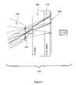
- FIG. 1shows a single-lens miniature imaging system according to the present invention.
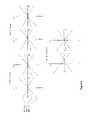
- FIG. 2illustrates a series of transverse ray intercept curves illustrating aberrations at various wavelengths for the system of FIG. 1 with wavefront coding removed.
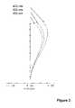
- FIG. 3illustrates distortion curves for the system of FIG. 1 with wavefront coding removed.
- FIG. 4illustrates modulation transfer functions (MTF) for the system of FIG. 1 with wavefront coding removed.
- MTFmodulation transfer functions
- FIG. 5illustrates MTFs for the system of FIG. 1 with wavefront coding, but without post processing.
- FIG. 6illustrates MTFs for the system of FIG. 1 with wavefront coding, before and after filtering.
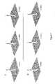
- FIGS. 7 a and 7 billustrate sampled point spread functions (PSF) for the system of FIG. 1 with wavefront coding and after filtering for two object distances.
- PSFsampled point spread functions
- FIG. 8shows a low cost microscope objective according to the present invention.
- FIG. 9illustrates a series of transverse ray intercept curves illustrating aberrations at various wavelengths for the system of FIG. 8 with wavefront coding removed.
- FIG. 10illustrates MTFs for the system of FIG. 8 with wavefront coding, without wavefront coding, and with wavefront coding and filtering.
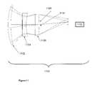
- FIG. 11shows a passive athermalized IR imaging system according to the present invention.
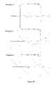
- FIG. 12illustrates a series of transverse ray intercept curves illustrating aberrations at various wavelengths for the system of FIG. 11 without wavefront coding.
- FIG. 13illustrates MTFs for the system of FIG. 11 without wavefront coding.
- FIG. 14illustrates MTFs for the system of FIG. 11 with wavefront coding, with and without filtering.
- FIG. 15 aillustrates transverse ray intercept curves as typically implemented in traditional imaging systems.
- FIG. 15 bshows MTFs for the system of FIG. 15 a.
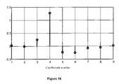
- FIG. 16illustrates an example of a one dimensional separable filter for use as a post processing element in the present invention.
- FIG. 17illustrates the magnitude of the transfer function of the filter of FIG. 16 .
- FIG. 1shows a single-lens miniature imaging system 100 according to the present invention.
- Lens 102includes wavefront coding element 104 formed on its second surface.
- Detector 106is preceded by an infrared (IR) filter 108 and cover glass 110 .
- Post processing filter 112performs processing on the images captured by detector 106 .
- the examplary single-lens imaging system (singlet) 100is designed to meet the following specifications:
- the exemplary singlet 100without Wavefront Coding element 104 , was designed so that the aberrations that are not corrected by the optical surfaces, namely petzval curvature and axial chromatic aberration, are a type of misfocus.
- petzval curvatureis a type of misfocus with field angle
- axial chromatic aberrationis misfocus with illumination wavelength.
- the effect of these aberrationscould hypothetically be corrected within small regions of the image plane by changing the focus position.
- the resulting MTFs and PSFswill be insensitive to the focus-like aberrations.
- the MTFs and PSFswill not be the same as an ideal in-focus MTF or PSF from a traditional imaging system. Image processing is required to restore the spatial character of the image and produce a sharp and clear image.
- the parameter r nis a normalized radius value.
- This particular Wavefront Coding surfaceis rectangularly separable and allows for fast software processing.
- Other forms of Wavefront Coding surfacesare nonseparable and are the sum of rectangularly separable forms.
- Wavefront Coding surface for singlet 100 in this exampleis placed at the stop surface (e.g., Wavefront Coding element 104 ) and has the parameterized equation:
- FIGS. 2-4illustrate the performance of system 100 with wavefront coding element 104 removed, in order to illustrate design requirements and performance.
- FIG. 5illustrates the performance of system 100 with wavefront coding element 104 in place, but without post processing filter 112 .
- FIG. 6illustrates the performance improvement with post processing 112 .
- FIGS. 7 a and 7 bshow PSFs for system 100 with both wavefront coding and post processing.
- FIG. 2illustrates a series of transverse ray intercept curves illustrating aberrations at various wavelengths, for the system of FIG. 1 with wavefront coding element 104 removed for illustrative purposes. Curves are shown for system 100 at half field angles of 0°, 10°, 20° and 25° off axis, and for illumination wavelengths of 450 nm, 550 nm, and 650 nm. A slope of zero indicates an in-focus condition. Thus on-axis rays are nearly in focus. But, for off axis field angles, the slopes of the transverse ray intercept curves increase dramatically.
- FIG. 15 aillustrates traditional transverse ray plots. These plots are taken from “Practical Computer Aided Lens Design”, Gregory Hallick Smith, William Bell, Inc., Richmond 1998. Note that the plot for near on axis rays do look similar to straight horizontal lines, and thus produce an in focus image.
- FIG. 15 bwhich shows associated MTFs for this system. The MTFs for near on axis rays are good. But as the rays move further off axis, the plots in FIG. 15 a quickly deviate from being straight lines. Their associated MTFs in 15 b also quickly degrade.
- the transverse ray intercept curves of FIG. 2are essentially straight lines, both on and off axis. This is a deliberate design goal, because the use of wavefront coding element 104 and post processing filter 112 can bring the captured images into focus, so long as the curves without wavefront coding are essentially straight lines through the origin, even if the lines are significantly sloped. The effect of the slope is removed by adding wavefront coding and post processing.
- the aberration petzval curvaturegives rise to transverse ray intercept curves, with slopes that are a function of field angle.
- Axial chromatic aberrationgives rise to ray intercept curves with slopes that are a function of illumination wavelength. From FIG. 2 , both of these features are part of the transverse ray intercept curves in this examplary design.
- FIG. 3illustrates distortion curves for system 100 of FIG. 1 , with wavefront coding element 104 removed.
- the distortionis less than 0.2%. If distortion was large enough then additional digital processing might be required to reposition image points into a non-distorted image.
- Table 1lists the optical prescription of this lens, again without the Wavefront Coding surface. Units are in mm, and the total length is 4.1 mm. Aspheric terms describe rotationally symmetric forms of r order with order equal to 4, 6, 8, etc.
- FIG. 4illustrates MTFs for system 100 of FIG. 1 , without wavefront coding element 104 .
- These MTFscorrespond to the transverse ray aberration curves of FIG. 2 .
- the MTFsare for half field angles 0, 15, and 25 degrees with wavelengths of 550 nm.
- the MTFsinclude the pixel MTF due to the Bayer color filter array detector with six micron pixels and 100% fill factor.
- the on-axis MTFis essentially diffraction limited.
- the large drop in MTF off-axisis due to the large amount of petzval curvature that is unavoidable in traditional single lens designs with a large field of view.
- This singlet without wavefront coding 104does not meet the MTF specification of greater than 40% modulation at 40 lp/mm for all field angles. But, due to its design for Wavefront Coding, modifying the second surface with a Wavefront Coding surface on element 104 will lead to acceptable MTF modulation values when combined with digital processing. By changing the wavefront coding element 104 either more or less sensitivity to misfocus aberrations can be formed.
- FIG. 5illustrates MTFs for system 100 of FIG. 1 with wavefront coding element 104 in place but without post processing filter 112 .
- the systemis focused at infinity.
- the half field angles shownare 0, 15, and 25 degrees.
- the wavelengthis 550 nm.
- These MTFshave very little variation with field angle due to the addition of the Wavefront Coding surface, as compared to FIG. 4 .
- Pixel MTF due to the Bayer CFAhas again been included.
- the Bayer CFA with 6 ⁇ m 100% fill factor pixelshas a Nyquist spatial frequency of about 42 lp/mm. Note that there are purposely no zeros in the MTFs below the detector's Nyquist spatial frequency.
- FIG. 6illustrates MTFs for system 100 of FIG. 1 , with wavefront coding element 104 and after processing filter 112 .
- Applying a single digital filter in processing block 112gives the optical/digital MTFs shown in FIG. 6 .
- the MTFs before filteringare as shown in FIG. 5 .
- the MTFs after processing filter 112 at the spatial frequency of 40 lp/mmare all above 40% as specified by the design specifications.
- the level of the MTFs after processingcould further be increased beyond that of the traditional diffraction-limited case, but possibly at the expense of a lower signal to noise ratio of the final image.
- FIGS. 7 a and 7 billustrate sampled two-dimensional PSFs for system 100 of FIG. 1 , with wavefront coding element 104 and after processing filter 112 .
- FIG. 7 ashows the processed PSFs when the object is at infinity.
- FIG. 7 bshows the processed PSFs when the object is at 30 cm. These PSFs are for 550 nm wavelength and half field angles of 0, 15, and 25 degrees. After filtering, these PSFs have nearly ideal shapes. This singlet 100 when combined with wavefront coding and digital filtering thus easily meets the system specifications.
- processing filter 112is a rectangularly separable digital filter. Rectangularly separable filters are more computationally efficient (counting the number of multiplications and additions) than full 2D kernel filters. Separable filtering consists of filtering each row of the image with the 1D row filter and forming an intermediate image. The columns of the intermediate image are then filtered with the 1D column filter to provide the final in-focus image.
- the separable filter used for this exemplary singlethas the same filters for rows and columns.
- FIG. 16illustrates an example of a one dimensional separable filter as used as processing filter 112 .
- Coefficientsare represented as real values, but can be quantified into integer values for fixed point computations.
- the sum of the filter coefficientsequals approximately 1.
- the coefficientswere determined with a least squares algorithm by minimizing the squared difference between the filtered wavefront coded optical transfer functions (OTF) and a desired MTF with a value greater than 40% at 40 lp/mm.
- the width of the filtered PSFs of FIGS. 7 a and 7 bare also minimized with the least squares algorithm. Changes in the filtered PSFs are minimized in regions away from their central peaks.
- FIG. 17illustrates the magnitude of the transfer function of the filter of FIG. 16 .
- the zero spatial frequency valueis 1.
- Wavefront coding microscope objective 800is designed to meet the following objectives:
- the depth of field of traditional microscope objectivesis described by the numerical aperture (NA) and the imaging wavelength.
- the wavefront coding objectivecan have a depth of field that is independent of the NA of the objective.
- the depth of fieldcan be large enough to introduce prospective distortion to the final images. Regions of the object that are farther from the objective will appear smaller than regions of the object closer to the objective. Both near and far regions can image clearly with a large depth of field. Since the depth of field of traditional objectives is small, prospective distortion is not common with traditional objectives, especially with high NA. Prospective distortion can be reduced or eliminated by designing wavefront coding objectives that are telecentric. In telecentric imaging systems the magnification of the object is independent of the distance to the object.
- FIG. 9illustrates a series of transverse ray intercept curves illustrating aberrations at various wavelengths, for system 800 of FIG. 8 , with wavefront coding element 806 removed.
- the ray intercept curves of FIG. 9describe the performance of the system at wavelengths 450 nm, 550 nm and 650 nm for the image field heights of on-axis 0.0 mm, 1.2 mm and 2.8 mm. Full scale is +/ ⁇ 100 microns. Notice that each of these ray intercept curves vary mainly in slope, as required by the present invention (e.g., the shape of the curves are essentially the same when the slope components of the curves are not considered). While these plots are not quite as close to perfectly straight lines as those in FIG. 2 , they can still be considered to be sloped substantially straight lines.
- Wavefront coding element 806is placed at aperture stop 804 , and is given by the rectangularly separable form of:
- FIG. 10illustrates MTFs for system 800 of FIG. 8 with wavefront coding, without wavefront coding, and with both wavefront coding and post processing filtering, for illumination at 450 nm.
- Image field heightsare 0.0 mm, 1.2 mm and 2.8 mm.
- FIG. 11shows a passive athermalized IR imaging system 1100 according to the present invention.
- Lens 1102is composed of silicon.
- Lens 1104is composed of germanium.
- Lens 1106is composed of silicon.
- the aperture stop 1108is at the back surface of lens 1106 .
- Wavefront coding surface 1110is on the back surface of lens 1106 (at aperture stop 1108 ).
- Processing block 1112processes the image.
- Table 4gives the optical prescription of system 1100 .
- the Wavefront Coding surface for IR system 100 of this examplehas the parameterized equation:
- FIG. 12illustrates a series of transverse ray intercept curves illustrating aberrations at various wavelengths, for system 1100 of FIG. 11 , with wavefront coding element 1110 removed.
- the ray intercept curves of FIG. 11describe the performance of system 1100 at a wavelength of 10 microns, on axis field points for ambient temperatures of +20° C., ⁇ 20° C., and +70° C. Full scale is +/ ⁇ 100 microns. Again these plots can be considered to be substantially straight lines. While they have more “wiggle” than the plots of FIGS. 2 and 9 , in each case, if the plot were fitted to the closest straight line, the wiggles would not stray far from the line.
- FIG. 13illustrates on-axis MTF curves for system 1100 without wavefront coding at three temperatures (+20°, ⁇ 20° and +70°). Performance is nearly diffraction limited at +20°, but drops dramatically with changes in temperature.
- FIG. 14illustrates MTFs for system 1100 of FIG. 11 , with wavefront coding, both with and without filtering by processing block 1112 .
- the illumination wavelengthis 10 microns.
- the MTFs without filteringare significantly different from diffraction limited MTFs, but vary little with temperature. Thus, processing block 1112 is able to correct the images.
- the MTFs after filteringare near diffraction limited for all three temperatures (+20°, ⁇ 20° and +70°). Filtered MTFs extend only to the Nyquist frequency of the 20 micron detector, or 25 lp/mm.
- One preferred way to define what constitutes a transverse ray intercept curve that is a “substantially straight line”is to look at the MTFs over the entire useful range of the system with wavefront coding applied. These curves must be very close to each other, in order for the post processing to be able to move all MTFs to the desired performance level. Compare the MTFs of FIG. 4 (e.g., no wavefront coding) to those of FIG. 5 (e.g., wavefront coding). The FIG. 5 MTF curves are very close together. In FIG. 6 , post processing has moved the MTFs to an acceptable level. More sophisticated post processing could improve the MTFs much further, to nearly diffraction limited performance, so long as the preprocessing curves are close enough together. Post processing could not accomplish this goal with the curves of FIG. 4 , because they are not close together.
- FIG. 10also illustrates this concept.
- the MTF curves without wavefront codingdo not track each other.
- the curves with wavefront codingare close together.
- the curves with wavefront coding after post processingare very good.
- the MTF curves without wavefront codingare far apart, but the MTF curves with wavefront coding (e.g., FIG. 14 ) are close enough together that the post processing curves are nearly diffraction limited.
- a lower level of performancemay be acceptable, and consequently the deviation of the transverse ray intercept curves from a straight line may be larger.
- a fast lenssay F/2
- the diffraction limited MTF for the optical systemwould extend to 1000 lp/mm, but the highest spatial frequency that could be measured by the detector would be only 50 lp/mm.
- aberrations that alter the highest spatial frequencies of the opticsare of no consequence, because they will not be measured by the detector.
- transverse ray intercept curvesmay have noticeable deviations from a straight line (corresponding to the higher spatial frequencies)
- the transverse ray intercept curvesare still “substantially straight lines” according to our definition, because the MTFs with wavefront coding are close together.
- the MTFs under considerationare those that correspond to the useful range of the particular system being considered.
Landscapes
- Physics & Mathematics (AREA)
- General Physics & Mathematics (AREA)
- Optics & Photonics (AREA)
- Lenses (AREA)
- Studio Devices (AREA)
Abstract
Description
This patent application is a continuation of commonly-owned and U.S. patent application Ser. No. 11/192,572, filed 29 Jul. 2005, now U.S. Pat. No. 7,106,510, which is a continuation of U.S. patent application Ser. No. 10/407,708, filed Apr. 4, 2003, now U.S. Pat. No. 6,940,649, which is a continuation of U.S. patent application Ser. No. 09/747,788, now abandoned, filed Dec. 22, 2000. This patent application is also a continuation-in-part of commonly-owned and U.S. patent application Ser. No. 09/070,969, filed May 1, 1998, now U.S. Pat. No. 7,218,448, which is a continuation-in-part of U.S. patent application Ser. No. 08/823,894, filed Mar. 17, 1997, now U.S. Pat. No. 5,748,371, issued May 5, 1998, which is a continuation of U.S. patent application Ser. No. 08/384,257, filed Feb. 3, 1995, now abandoned. Each of the above-mentioned patents and patent applications are incorporated herein by reference. U.S. patent application Ser. No. 09/875,435, filed Jun. 6, 2001, now U.S. Pat. No. 6,525,302, U.S. patent application Ser. No. 09/875,766, filed Jun. 6, 2001, and U.S. patent application Ser. No. 09/766,325 filed Jan. 19, 2001, now U.S. Pat. No. 6,873,733, issued Mar. 29, 2005 are each incorporated herein by reference.
Traditional optical design is based on the premise that the only major components of the imaging system are the optics and detector. The detector can be analog (e.g. film) or a digital detector (e.g., CCD, CMOS, etc.). Traditional image processing techniques performed on an image are performed after the image is formed. Examples of traditional image processing include edge sharpening and color filter array (CFA) color interpolation. Traditional optics are therefore designed to form images at the detector that are sharp and clear over a range of field angles, illumination wavelengths, temperatures, and focus positions. Consequently, a trade off is made between forming good images, which requires optical designs that are larger, heavier, and contain more optical elements than are desirable, and modifying the design in order to reduce size, weight, or the number of optical elements, which results in loss of image quality.
A need remains in the art for improved optical designs which produce good images with systems that are smaller, lighter, and contain fewer elements than those based on traditional optics.
Optical design based on Wavefront Coding enables systems such that they can be smaller, lighter, and contain fewer optical elements than those based on traditional optics. Wavefront Coding systems share the task of image formation between optics and digital processing. Instead of the imaging system being primarily composed of optics and the detector, Wavefront Coding imaging systems are composed of optics, the detector, and processing of the detected image. The detector can in general be analog, such as film, or a digital detector. Since processing of the detected image is an integral part of the total system, the optics of Wavefront Coded imaging systems do not need to form sharp and clear images at the plane of the detector. It is only the images after processing that need to be sharp and clear.
Wavefront Coding, in general, corrects for known or unknown amounts of “misfocus-like” aberrations. These aberrations include misfocus, spherical aberration, petzval curvature, astigmatism, and chromatic aberration. System sensitivities to environmental parameters such as temperature and pressure induced aberrations, and mechanical focus related aberrations from fabrication error, assembly error, drift, wear, etc., are also reduced with Wavefront Coding. Optical designs based on Wavefront Coding can reduce the effects of these aberrations and result in simpler designs that produce good images.
Optical system designs according to the present invention are improved in that they have the characteristic that the transverse ray intercept curves are substantially straight lines. Unlike traditional optical designs, the transverse ray intercept curves for wavefront coded systems need not have a near zero slope; the slope, which indicates misfocus, may be substantial, because wavefront coding allows the effects due to misfocus to be removed. In actual systems, the transverse ray intercept curves should vary mainly in slope over wavelength, field angles, temperature, etc., but need not be exactly straight lines; some ripple is acceptable. With wavefront coding optical surfaces and post processing, good images can be produced.
In one embodiment, a singlet imaging system for imaging an object onto a detector includes a lens configured for producing transverse ray intercept curves which are substantially straight, sloped lines. A wavefront coding element is formed on a surface of the lens and configured such that a modulation transfer function of the lens and wavefront coding element, combined, exhibits reduced variation, over a range of spatial frequencies and caused, at least in part, by aberrations of the lens, as compared to a modulation transfer function of the lens alone, without the wavefront coding element. A post processor is configured for generating an improved modulation transfer function, over the range of spatial frequencies, as compared to the modulation transfer function of the lens and the wavefront coding element.
Another embodiment is an improved imaging system for imaging an object onto a detector, the imaging system including a lens configured for producing transverse ray intercept curves that are substantially straight, sloped lines. The improvement includes a wavefront coding element formed on a surface of the lens and configured such that a modulation transfer function of the lens and the wavefront coding element, combined, exhibits reduced variation, over a range of spatial frequencies and caused, at least in part, by aberrations of the lens, as compared to a modulation transfer function of the lens alone, without the wavefront coding element. The improvement also includes a post-processor configured for generating an improved modulation transfer function, over the range of spatial frequencies, as compared to the modulation transfer function of a combination of the lens and the wavefront coding element.
The examplary single-lens imaging system (singlet)100 is designed to meet the following specifications:
- f=2.5 mm
- F/#=2.6
- Length<4.5 mm
- Material: Polymethylmethacrylate (PMMA)
- FOV=50°
- Focus: ∞−30 cm
- pixel size=6 μm
- Bayer CFA/100% fill factor
- MTF>40% at 40 1p/mm.
Theexemplary singlet 100, withoutWavefront Coding element 104, was designed so that the aberrations that are not corrected by the optical surfaces, namely petzval curvature and axial chromatic aberration, are a type of misfocus. Specifically, petzval curvature is a type of misfocus with field angle, and axial chromatic aberration is misfocus with illumination wavelength. The effect of these aberrations could hypothetically be corrected within small regions of the image plane by changing the focus position. By adding a Wavefront Coding surface, the resulting MTFs and PSFs will be insensitive to the focus-like aberrations. However, the MTFs and PSFs will not be the same as an ideal in-focus MTF or PSF from a traditional imaging system. Image processing is required to restore the spatial character of the image and produce a sharp and clear image.
The form of the Wavefront Coding surface used in this example is
where the sum is over the index i. Sign(x)=−1 for x<0, +1 for x≧0.
The parameter rnis a normalized radius value. This particular Wavefront Coding surface is rectangularly separable and allows for fast software processing. Other forms of Wavefront Coding surfaces are nonseparable and are the sum of rectangularly separable forms. One non-separable form is defined as:
S(r,θ)=Σαir60i cos(biθ+φi), (Eq. 2)
where the sum is again over the subscript i.
S(r,θ)=Σαir60
where the sum is again over the subscript i.
There are an infinite number of Wavefront Coding surface forms. The Wavefront Coding surface forsinglet 100 in this example is placed at the stop surface (e.g., Wavefront Coding element104) and has the parameterized equation:
- and the parameter values for i=1, 2, 3 are:
- a1=17.4171, b1=2.9911
- a2=10.8895, b2=6
- a3=3.8845, b3=20.1909
- rn=0.459.
- a1=17.4171, b1=2.9911
- and the parameter values for i=1, 2, 3 are:
There are numerous traditional methods of designing lenses. Most methods try to balance aberrations in order to improve the off-axis imaging at the expense of on-axis imaging or system simplicity. Traditional design methodologies do not attempt to make the transverse ray intercept curves straight lines. Instead, the traditional goal is to try to minimize the distance of a substantial portion of the transverse ray intercept curves from the horizontal axis. In most traditional systems the ray intercept curves are very different from straight lines, but in general lie closer to the horizontal axis than the off-axis curves shown inFIG. 2 . In other words, in traditional systems the variation from a straight horizontal line is mainly in the straightness of the line, rather than in its slope.
The transverse ray intercept curves ofFIG. 2 are essentially straight lines, both on and off axis. This is a deliberate design goal, because the use ofwavefront coding element 104 and postprocessing filter 112 can bring the captured images into focus, so long as the curves without wavefront coding are essentially straight lines through the origin, even if the lines are significantly sloped. The effect of the slope is removed by adding wavefront coding and post processing.
The aberration petzval curvature gives rise to transverse ray intercept curves, with slopes that are a function of field angle. Axial chromatic aberration gives rise to ray intercept curves with slopes that are a function of illumination wavelength. FromFIG. 2 , both of these features are part of the transverse ray intercept curves in this examplary design.
| TABLE 1 | |||||
| Surface | Radius | Thickness | Material | Diameter | |
| Inf | Inf | 0 | |||
| 1 | 2.077 | 1.7133 | 2 | ||
| Stop | −2.236 | 0.6498 | 1.4 | ||
| 3 | Inf | 1.1 | BK7 | 3.4 | |
| 4 | Inf | 0.55 | BK7 | 3.4 | |
| Img | 0.1 | 3.4 | |||
| Surface | Conic | 4th Asph. | 6th Asph. | 8th Asph. | |
| 0 | |||||
| 1 | −1.299 | −.000375 | −.010932 | −.00603 | |
| Stop | −3.140 | −.01049 | |||
| 3 | 0 | ||||
| 4 | 0 | ||||
| Img | |||||
In one preferred embodiment, processingfilter 112 is a rectangularly separable digital filter. Rectangularly separable filters are more computationally efficient (counting the number of multiplications and additions) than full 2D kernel filters. Separable filtering consists of filtering each row of the image with the 1D row filter and forming an intermediate image. The columns of the intermediate image are then filtered with the 1D column filter to provide the final in-focus image. The separable filter used for this exemplary singlet has the same filters for rows and columns.
Wavefrontcoding microscope objective 800 is designed to meet the following objectives:
- magnification=10×
- N.A.=0.15
- Distortion<1%
- 7 micron square pixels with 100% fill factor
- VGA grayscale detector
- Optical material: PMMA.
The depth of field of traditional microscope objectives is described by the numerical aperture (NA) and the imaging wavelength. The wavefront coding objective can have a depth of field that is independent of the NA of the objective. The depth of field can be large enough to introduce prospective distortion to the final images. Regions of the object that are farther from the objective will appear smaller than regions of the object closer to the objective. Both near and far regions can image clearly with a large depth of field. Since the depth of field of traditional objectives is small, prospective distortion is not common with traditional objectives, especially with high NA. Prospective distortion can be reduced or eliminated by designing wavefront coding objectives that are telecentric. In telecentric imaging systems the magnification of the object is independent of the distance to the object.
The major aberration apparent in this design is axial chromatic aberration, with a smaller amount of petzval curvature and lateral chromatic aberration. Without Wavefront Coding this lens would image poorly in white light, although it might produce a reasonable image in a single color. Tables 2 and 3 give the optical prescription for this system. Table 3 gives rotationally symmetric aspheric terms for the system.
| TABLE 2 | |||||
| Radius | |||||
| Surface | of curv | Thickness | Material | Diameter | Conic |
| Obj | Inf | 2.45906 | 0.6357861 | 0 | |
| 1 | 1.973107 | 1.415926 | Acrylic | 1.2 | −1.680295 |
| 2 | −2.882275 | 0.7648311 | 1.2 | −1.029351 | |
| Stop | Inf | 0.1 | Acrylic | 0.841 | 0 |
| 4 | Inf | 25.83517 | 0.841 | 0 | |
| Img | 6.173922 | ||||
| TABLE 3 | ||||||
| Surface | 4th | 6th | 8th | 10th | 12th | 14th |
| 1 | 0.013191 | −0.22886 | 0.139609 | −0.250285 | −0.18807 | 0.193763 |
| 2 | −0.008797 | 0.017236 | 0.007808 | −0.223224 | 0.160689 | −0.274339 |
| Stop | −0.018549 | −0.010249 | −0.303999 | 1.369745 | 11.245778 | −59.7839958 |
- and the parameter values for i=1, 2 are:
- a1=1.486852, b1=3.0
- a2=3.221235, b2=10.0
- rn=0.419.
- and the parameter values for i=1, 2 are:
Design goals are as follows:
- F/2
- f=100 mm
- 3 deg half field of view
- Illumination wavelength=10 microns
- 20 micron square pixels, 100% fill factor
Silicon & germanium optics
- Aluminum mounts
- Temperature range of −20° C. to +70° C.
Combined constraints of low F/#, inexpensive mounting material, and wide operating temperature make this design very difficult for traditional optics. Table 4 gives the optical prescription ofsystem 1100.
| TABLE 4 | |||||
| Radius | |||||
| Surface | of curv | Thickness | Material | Diameter | Conic |
| Obj | Inf | Inf | 0.6357861 | 0 | |
| 1 | 58.6656 | 5.707297 | 60 | 0 | |
| 2 | 100.9934 | 22.39862 | 57.6 | 0 | |
| 3 | 447.046 | 8.000028 | Germanium | 32.4 | 0 |
| 4 | 50.88434 | 17.54754 | 32.4 | 0 | |
| 5 | 455.597 | 7.999977 | Silicon | 29.5 | 0 |
| Stop | −115.6064 | 57.9967 | 29.5 | 0 | |
| Img | 6.173922 | ||||
The Wavefront Coding surface forIR system 100 of this example has the parameterized equation:
- and the parameter values for i=1, 2 are:
- a1=16.196742, b1=3.172720
- a2=−311.005659, b2=20.033486
- rn=18.314428.
- and the parameter values for i=1, 2 are:
One preferred way to define what constitutes a transverse ray intercept curve that is a “substantially straight line” is to look at the MTFs over the entire useful range of the system with wavefront coding applied. These curves must be very close to each other, in order for the post processing to be able to move all MTFs to the desired performance level. Compare the MTFs ofFIG. 4 (e.g., no wavefront coding) to those ofFIG. 5 (e.g., wavefront coding). TheFIG. 5 MTF curves are very close together. InFIG. 6 , post processing has moved the MTFs to an acceptable level. More sophisticated post processing could improve the MTFs much further, to nearly diffraction limited performance, so long as the preprocessing curves are close enough together. Post processing could not accomplish this goal with the curves ofFIG. 4 , because they are not close together.
InFIGS. 13 and 14 , the MTF curves without wavefront coding (e.g.,FIG. 13 ) are far apart, but the MTF curves with wavefront coding (e.g.,FIG. 14 ) are close enough together that the post processing curves are nearly diffraction limited.
InFIG. 13 , it can be seen that the on-axis MTF (at +20° C., meaning essentially no temperature related misfocus) is essentially diffraction limited. This is the best case traditional MTF for this system. The MTFs at other temperatures, though, have greatly reduced performance due to temperature related effects.
Now consider the upper set of MTFs ofFIG. 14 , with wavefront coding and after processing. The MTFs are nearly identical. Thus the associated transverse ray intercept curves can be considered to be substantially straight lines, since they are close enough to straight to give essentially ideal MTFs.
For other systems, a lower level of performance may be acceptable, and consequently the deviation of the transverse ray intercept curves from a straight line may be larger. Such a situation would result if a fast lens (say F/2) is used with a digital detector, with, for example, 10 micron pixels. In 500 nm illumination, the diffraction limited MTF for the optical system would extend to 1000 lp/mm, but the highest spatial frequency that could be measured by the detector would be only 50 lp/mm. Thus, aberrations that alter the highest spatial frequencies of the optics are of no consequence, because they will not be measured by the detector. Note that while the transverse ray intercept curves may have noticeable deviations from a straight line (corresponding to the higher spatial frequencies), the transverse ray intercept curves are still “substantially straight lines” according to our definition, because the MTFs with wavefront coding are close together. The MTFs under consideration are those that correspond to the useful range of the particular system being considered.
Compare the MTFs ofFIGS. 6 ,10, and14 with wavefront coding (e.g., useful range MTFs for embodiments of the present invention) with the MTFs resulting from traditional design ofFIG. 15 b. These traditional MTFs are quite far apart, so post processing could never give adequate performance. These curves are generally 50% or more apart, whereas the wavefront coding curves inFIGS. 6 ,10, and14, are within an average of 20% of each other over the useful range of the system, and, in the case ofFIG. 10 , are within an average of 10% of each other over the useful range of the system.
The major aberration apparent in the design ofFIG. 11 is temperature related misfocus. Without Wavefront Coding, this lens would image poorly over a range of temperatures.
Claims (18)
1. A singlet imaging system for imaging an object onto a detector, comprising:
a lens configured for producing transverse ray intercept curves which are substantially straight, sloped lines;
a wavefront coding element formed on a surface of the lens and configured such that a modulation transfer function of the lens and wavefront coding element, combined, exhibits reduced variation, over a range of spatial frequencies and caused, at least in part, by aberrations of the lens, as compared to a modulation transfer function of the lens alone, without the wavefront coding element; and
a post processor configured for generating an improved modulation transfer function, over the range of spatial frequencies, as compared to the modulation transfer function of the lens and the wavefront coding element.
2. The singlet imaging system ofclaim 1 , wherein the post processor includes a digital filter.
3. The singlet imaging system ofclaim 2 , wherein the digital filter includes a separable filter.
4. The singlet imaging system ofclaim 1 , wherein the wavefront coding element is formed on a surface of the lens furthest from the object.
5. The singlet imaging system ofclaim 1 , said lens including a front surface defining a lens length between said front surface and said detector, the lens length being less than 5 mm.
6. The singlet imaging system ofclaim 1 , wherein the wavefront coding element forms one of a rectangularly separable surface, a non-separable surface, and a surface having a sum of rectangularly separable forms.
7. The singlet imaging system ofclaim 1 , wherein the lens is configured to transmit in an infrared wavelength range, and wherein the aberrations include temperature induced misfocus aberrations.
8. The singlet imaging system ofclaim 1 , wherein the wavefront coding element is formed on a surface of the lens nearest to the object.
9. The singlet imaging system ofclaim 1 , wherein the wavefront coding element is further configured such that the modulation transfer function of the lens and wavefront coding element exhibits the reduced variation over a field of view of at least approximately fifty degrees.
10. The singlet imaging system ofclaim 1 , wherein the lens provides a magnification greater than one, and wherein the aberrations include at least one of chromatic aberration, petzval curvature and field curvature.
11. In an imaging system for imaging an object onto a detector, the imaging system including a lens configured for producing transverse ray intercept curves that are substantially straight, sloped lines, an improvement comprising:
a wavefront coding element formed on a surface of the lens and configured such that a modulation transfer function of the lens and the wavefront coding element, combined, exhibits reduced variation, over a range of spatial frequencies and caused, at least in part, by aberrations of the lens, as compared to a modulation transfer function of the lens alone, without the wavefront coding element; and
a post-processor configured for generating an improved modulation transfer function, over the range of spatial frequencies, as compared to the modulation transfer function of the lens and the wavefront coding element.
12. In the system ofclaim 11 , the further improvement wherein the post processor includes a digital filter.
13. In the system ofclaim 12 , the further improvement wherein the digital filter includes a separable filter.
14. In the system ofclaim 11 , the further improvement wherein the wavefront coding element is fonned on a surface of the lens furthest from the object.
15. In the system ofclaim 11 , the further improvement wherein the lens includes a front surface defining a lens length between the front surface and the detector, the lens length being less than 5 mm.
16. In the system ofclaim 11 , the further improvement wherein the wavefront coding element includes a selected one of a rectangularly separable surface, a non-separable surface, and a surface having a sum of rectangularly separable forms.
17. In the system ofclaim 11 , the further improvement wherein the wavefront coding element is further configured such that the modulation transfer function of the lens and the wavefront coding element, combined, exhibits the reduced variation over a field of view of at least approximately 50 degrees.
18. In the system ofclaim 11 , the further improvement wherein the lens provides a magnification greater than one, and wherein the aberrations include at least one of chromatic aberration, petzval curvature and field curvature.
Priority Applications (1)
| Application Number | Priority Date | Filing Date | Title |
|---|---|---|---|
| US11/511,023US7554732B2 (en) | 1995-02-03 | 2006-08-28 | Wavefront coded imaging systems |
Applications Claiming Priority (7)
| Application Number | Priority Date | Filing Date | Title |
|---|---|---|---|
| US38425795A | 1995-02-03 | 1995-02-03 | |
| US08/823,894US5748371A (en) | 1995-02-03 | 1997-03-17 | Extended depth of field optical systems |
| US09/070,969US7218448B1 (en) | 1997-03-17 | 1998-05-01 | Extended depth of field optical systems |
| US09/747,788US20020118457A1 (en) | 2000-12-22 | 2000-12-22 | Wavefront coded imaging systems |
| US10/407,708US6940649B2 (en) | 1995-02-03 | 2003-04-04 | Wavefront coded imaging systems |
| US11/192,572US7106510B2 (en) | 1995-02-03 | 2005-07-29 | Wavefront coded imaging systems |
| US11/511,023US7554732B2 (en) | 1995-02-03 | 2006-08-28 | Wavefront coded imaging systems |
Related Parent Applications (2)
| Application Number | Title | Priority Date | Filing Date |
|---|---|---|---|
| US09/070,969Continuation-In-PartUS7218448B1 (en) | 1995-02-03 | 1998-05-01 | Extended depth of field optical systems |
| US11/192,572ContinuationUS7106510B2 (en) | 1995-02-03 | 2005-07-29 | Wavefront coded imaging systems |
Related Child Applications (1)
| Application Number | Title | Priority Date | Filing Date |
|---|---|---|---|
| US10/407,708ContinuationUS6940649B2 (en) | 1995-02-03 | 2003-04-04 | Wavefront coded imaging systems |
Publications (2)
| Publication Number | Publication Date |
|---|---|
| US20070076296A1 US20070076296A1 (en) | 2007-04-05 |
| US7554732B2true US7554732B2 (en) | 2009-06-30 |
Family
ID=25006641
Family Applications (5)
| Application Number | Title | Priority Date | Filing Date |
|---|---|---|---|
| US09/747,788AbandonedUS20020118457A1 (en) | 1995-02-03 | 2000-12-22 | Wavefront coded imaging systems |
| US10/407,708Expired - LifetimeUS6940649B2 (en) | 1995-02-03 | 2003-04-04 | Wavefront coded imaging systems |
| US11/192,572Expired - LifetimeUS7106510B2 (en) | 1995-02-03 | 2005-07-29 | Wavefront coded imaging systems |
| US11/511,022Expired - LifetimeUS7554731B2 (en) | 1995-02-03 | 2006-08-28 | Wavefront coded imaging systems |
| US11/511,023Expired - LifetimeUS7554732B2 (en) | 1995-02-03 | 2006-08-28 | Wavefront coded imaging systems |
Family Applications Before (4)
| Application Number | Title | Priority Date | Filing Date |
|---|---|---|---|
| US09/747,788AbandonedUS20020118457A1 (en) | 1995-02-03 | 2000-12-22 | Wavefront coded imaging systems |
| US10/407,708Expired - LifetimeUS6940649B2 (en) | 1995-02-03 | 2003-04-04 | Wavefront coded imaging systems |
| US11/192,572Expired - LifetimeUS7106510B2 (en) | 1995-02-03 | 2005-07-29 | Wavefront coded imaging systems |
| US11/511,022Expired - LifetimeUS7554731B2 (en) | 1995-02-03 | 2006-08-28 | Wavefront coded imaging systems |
Country Status (4)
| Country | Link |
|---|---|
| US (5) | US20020118457A1 (en) |
| EP (1) | EP1346251A2 (en) |
| AU (1) | AU2002219861A1 (en) |
| WO (1) | WO2002052331A2 (en) |
Cited By (4)
| Publication number | Priority date | Publication date | Assignee | Title |
|---|---|---|---|---|
| US20070252975A1 (en)* | 2006-04-28 | 2007-11-01 | Chao-Wen Liang | Phase shifting grating-slit test for optical surface reconstruction |
| US20090018465A1 (en)* | 2006-01-06 | 2009-01-15 | Phonak Ag | Method and system for reconstructing the three-dimensional shape of the surface of at least a portion of an ear canal and/or of a concha |
| US20090109535A1 (en)* | 1995-02-03 | 2009-04-30 | Cathey Jr Wade Thomas | Extended Depth Of Field Optical Systems |
| US20100328502A1 (en)* | 2009-06-30 | 2010-12-30 | Kabushiki Kaisha Toshiba | Image processing device, image processing method, and imaging apparatus |
Families Citing this family (96)
| Publication number | Priority date | Publication date | Assignee | Title |
|---|---|---|---|---|
| US20020195548A1 (en)* | 2001-06-06 | 2002-12-26 | Dowski Edward Raymond | Wavefront coding interference contrast imaging systems |
| US20020118457A1 (en) | 2000-12-22 | 2002-08-29 | Dowski Edward Raymond | Wavefront coded imaging systems |
| US6879412B1 (en)* | 2000-08-10 | 2005-04-12 | Mustek Systems Inc. | Method for optimizing the best resolution of an optical scanning system and apparatus for the same |
| US6707603B2 (en)* | 2001-06-28 | 2004-03-16 | Raytheon Company | Apparatus and method to distort an optical beam to avoid ionization at an intermediate focus |
| JP4249627B2 (en) | 2001-12-18 | 2009-04-02 | ザ ユニバーシティ オブ ロチェスター | Imaging to obtain an extended focal length using a multifocal aspheric lens |
| JP3791777B2 (en)* | 2001-12-28 | 2006-06-28 | オリンパス株式会社 | Electronic endoscope |
| WO2003073153A1 (en)* | 2002-02-27 | 2003-09-04 | Cdm Optics, Inc. | Optimized image processing for wavefront coded imaging systems |
| US8717456B2 (en) | 2002-02-27 | 2014-05-06 | Omnivision Technologies, Inc. | Optical imaging systems and methods utilizing nonlinear and/or spatially varying image processing |
| US7031054B2 (en)* | 2002-10-09 | 2006-04-18 | The Regent Of The University Of Colorado | Methods and systems for reducing depth of field of hybrid imaging systems |
| ATE549855T1 (en)* | 2003-01-16 | 2012-03-15 | Digitaloptics Corp Internat | METHOD FOR PRODUCING AN OPTICAL SYSTEM INCLUDING A PROCESSOR FOR ELECTRONIC IMAGE ENHANCEMENT |
| US7773316B2 (en)* | 2003-01-16 | 2010-08-10 | Tessera International, Inc. | Optics for an extended depth of field |
| US8294999B2 (en) | 2003-01-16 | 2012-10-23 | DigitalOptics Corporation International | Optics for an extended depth of field |
| US20070236573A1 (en)* | 2006-03-31 | 2007-10-11 | D-Blur Technologies Ltd. | Combined design of optical and image processing elements |
| EP1672912B1 (en) | 2003-01-16 | 2012-03-14 | DigitalOptics Corporation International | Method for producing an optical system including an electronic image enhancement processor |
| US7180673B2 (en)* | 2003-03-28 | 2007-02-20 | Cdm Optics, Inc. | Mechanically-adjustable optical phase filters for modifying depth of field, aberration-tolerance, anti-aliasing in optical systems |
| US7260251B2 (en)* | 2003-03-31 | 2007-08-21 | Cdm Optics, Inc. | Systems and methods for minimizing aberrating effects in imaging systems |
| CN100508074C (en) | 2003-05-30 | 2009-07-01 | Cdm光学有限公司 | Lithography systems and methods with extended depth of focus |
| US8254714B2 (en)* | 2003-09-16 | 2012-08-28 | Wake Forest University | Methods and systems for designing electromagnetic wave filters and electromagnetic wave filters designed using same |
| WO2005054927A2 (en)* | 2003-12-01 | 2005-06-16 | Cdm Optics, Inc. | System and method for optimizing optical and digital system designs |
| US7944467B2 (en)* | 2003-12-01 | 2011-05-17 | Omnivision Technologies, Inc. | Task-based imaging systems |
| US7336430B2 (en)* | 2004-09-03 | 2008-02-26 | Micron Technology, Inc. | Extended depth of field using a multi-focal length lens with a controlled range of spherical aberration and a centrally obscured aperture |
| WO2007011375A1 (en)* | 2004-09-13 | 2007-01-25 | Cdm Optics, Inc. | Iris image capture devices and associated systems |
| WO2006055094A1 (en) | 2004-09-14 | 2006-05-26 | Cdm Optics, Inc. | Low height imaging system and associated methods |
| US20060269150A1 (en)* | 2005-05-25 | 2006-11-30 | Omnivision Technologies, Inc. | Multi-matrix depth of field image sensor |
| US7616841B2 (en) | 2005-06-17 | 2009-11-10 | Ricoh Co., Ltd. | End-to-end design of electro-optic imaging systems |
| WO2007001025A1 (en)* | 2005-06-29 | 2007-01-04 | Kyocera Corporation | Biometric recognition system |
| JP4712631B2 (en)* | 2005-07-28 | 2011-06-29 | 京セラ株式会社 | Imaging device |
| KR100691268B1 (en)* | 2005-08-02 | 2007-03-12 | 삼성전기주식회사 | Optical system and image processing method for processing images using PSF |
| KR20080035689A (en)* | 2005-08-11 | 2008-04-23 | 글로벌 바이오닉 옵틱스 피티와이 엘티디 | Optical lens system |
| WO2008008084A2 (en)* | 2005-09-19 | 2008-01-17 | Cdm Optics, Inc. | Task-based imaging systems |
| US20070081224A1 (en)* | 2005-10-07 | 2007-04-12 | Robinson M D | Joint optics and image processing adjustment of electro-optic imaging systems |
| WO2007046205A1 (en)* | 2005-10-18 | 2007-04-26 | Kyocera Corporation | Image pickup apparatus and image processing method |
| US20070093993A1 (en)* | 2005-10-20 | 2007-04-26 | Stork David G | End-to-end design of electro-optic imaging systems using backwards ray tracing from the detector to the source |
| US20100066809A1 (en)* | 2006-02-15 | 2010-03-18 | Cdm Optics, Inc. | Deployable Image Sensor |
| KR101301448B1 (en)* | 2006-03-06 | 2013-08-28 | 옴니비젼 씨디엠 옵틱스 인코퍼레이티드 | ZOOM LENS SYSTEMS and METHOD FOR USE THEREOF |
| US20070239417A1 (en)* | 2006-03-31 | 2007-10-11 | D-Blur Technologies Ltd. | Camera performance simulation |
| US20070236574A1 (en)* | 2006-03-31 | 2007-10-11 | D-Blur Technologies Ltd. | Digital filtering with noise gain limit |
| EP2008242B1 (en) | 2006-04-03 | 2011-06-08 | OmniVision CDM Optics, Inc. | Optical imaging systems and methods utilizing nonlinear and/or spatially varying image processing |
| US8514303B2 (en)* | 2006-04-03 | 2013-08-20 | Omnivision Technologies, Inc. | Advanced imaging systems and methods utilizing nonlinear and/or spatially varying image processing |
| EP2016454A1 (en)* | 2006-05-09 | 2009-01-21 | Omnivision Cdm Optics, Inc. | Aberration-tolerant far infrared imaging system |
| US7692709B2 (en)* | 2006-05-12 | 2010-04-06 | Ricoh Co., Ltd. | End-to-end design of electro-optic imaging systems with adjustable optical cutoff frequency |
| US7889264B2 (en)* | 2006-05-12 | 2011-02-15 | Ricoh Co., Ltd. | End-to-end design of superresolution electro-optic imaging systems |
| JP2007322560A (en)* | 2006-05-30 | 2007-12-13 | Kyocera Corp | Imaging device, manufacturing apparatus and manufacturing method thereof |
| US7924341B2 (en)* | 2006-06-05 | 2011-04-12 | Ricoh Co., Ltd. | Optical subsystem with descriptors of its image quality |
| JP4749959B2 (en)* | 2006-07-05 | 2011-08-17 | 京セラ株式会社 | Imaging device, manufacturing apparatus and manufacturing method thereof |
| JP2008048293A (en)* | 2006-08-18 | 2008-02-28 | Kyocera Corp | Imaging device and method for manufacturing the same |
| WO2008087486A2 (en)* | 2006-09-14 | 2008-07-24 | Tessera Technologies Hungary Kft. | Imaging system with improved image quality and associated methods |
| EP2069851A4 (en)* | 2006-09-14 | 2010-02-24 | Tessera Tech Hungary Kft | IMAGING SYSTEM WITH ASSOUPLY ASSEMBLED TOLERANCES AND ASSOCIATED METHODS |
| JP4749984B2 (en)* | 2006-09-25 | 2011-08-17 | 京セラ株式会社 | Imaging device, manufacturing apparatus and manufacturing method thereof |
| JP4749985B2 (en)* | 2006-09-28 | 2011-08-17 | 京セラ株式会社 | Imaging device, manufacturing apparatus and manufacturing method thereof |
| JP5188397B2 (en)* | 2006-12-27 | 2013-04-24 | 京セラ株式会社 | Imaging apparatus and information code reading apparatus |
| US8567678B2 (en)* | 2007-01-30 | 2013-10-29 | Kyocera Corporation | Imaging device, method of production of imaging device, and information code-reading device |
| US8199246B2 (en)* | 2007-05-30 | 2012-06-12 | Fujifilm Corporation | Image capturing apparatus, image capturing method, and computer readable media |
| JP2009010730A (en)* | 2007-06-28 | 2009-01-15 | Kyocera Corp | Image processing method and imaging apparatus using the image processing method |
| FR2919733B1 (en)* | 2007-08-03 | 2010-04-09 | Dxo Labs | OPTICAL SYSTEM HAVING A DEVICE FOR INCREASING ITS FIELD DEPTH |
| JP2009041968A (en)* | 2007-08-07 | 2009-02-26 | Fujinon Corp | Method and device for evaluating lens on premise of restoration processing, and correction optical system for evaluation |
| JP4844979B2 (en)* | 2007-08-30 | 2011-12-28 | 京セラ株式会社 | Image processing method and imaging apparatus using the image processing method |
| US8077401B2 (en)* | 2007-10-03 | 2011-12-13 | Ricoh Co., Ltd. | Catadioptric imaging system |
| JP2009122514A (en)* | 2007-11-16 | 2009-06-04 | Fujinon Corp | Imaging system, imaging apparatus having the imaging system, portable terminal apparatus, onboard apparatus, medical apparatus, and method of manufacturing the imaging system |
| JP4813446B2 (en)* | 2007-11-16 | 2011-11-09 | 富士フイルム株式会社 | IMAGING SYSTEM, IMAGING DEVICE EQUIPPED WITH THIS IMAGING SYSTEM, PORTABLE TERMINAL DEVICE, IN-VEHICLE DEVICE, MEDICAL DEVICE, AND METHOD FOR PRODUCING IMAGING SYSTEM |
| JP4813447B2 (en) | 2007-11-16 | 2011-11-09 | 富士フイルム株式会社 | IMAGING SYSTEM, IMAGING DEVICE EQUIPPED WITH THIS IMAGING SYSTEM, PORTABLE TERMINAL DEVICE, IN-VEHICLE DEVICE, AND MEDICAL DEVICE |
| WO2009069752A1 (en)* | 2007-11-29 | 2009-06-04 | Kyocera Corporation | Imaging device and electronic apparatus |
| US8077247B2 (en) | 2007-12-07 | 2011-12-13 | Fujinon Corporation | Imaging system, imaging apparatus, portable terminal apparatus, onboard apparatus, medical apparatus and method of manufacturing the imaging system |
| US8111318B2 (en)* | 2007-12-07 | 2012-02-07 | Fujinon Corporation | Imaging system, imaging apparatus, portable terminal apparatus, onboard apparatus, medical apparatus and method of manufacturing the imaging system |
| EP2891918A1 (en)* | 2008-02-29 | 2015-07-08 | Global Bionic Optics Pty Ltd. | Single-lens extended depth-of-field imaging systems |
| US9865043B2 (en) | 2008-03-26 | 2018-01-09 | Ricoh Company, Ltd. | Adaptive image acquisition and display using multi-focal display |
| US8897595B2 (en) | 2008-03-26 | 2014-11-25 | Ricoh Co., Ltd. | Adaptive image acquisition for multiframe reconstruction |
| US9866826B2 (en) | 2014-11-25 | 2018-01-09 | Ricoh Company, Ltd. | Content-adaptive multi-focal display |
| US8363129B2 (en)* | 2008-06-27 | 2013-01-29 | Kyocera Corporation | Imaging device with aberration control and method therefor |
| JP4658162B2 (en)* | 2008-06-27 | 2011-03-23 | 京セラ株式会社 | Imaging apparatus and electronic apparatus |
| US7948550B2 (en)* | 2008-06-27 | 2011-05-24 | Ricoh Co., Ltd. | Electro-optic imaging system with aberrated triplet lens compensated by digital image processing |
| US8248684B2 (en)* | 2008-08-26 | 2012-08-21 | Ricoh Co., Ltd. | Control of adaptive optics based on post-processing metrics |
| US8502877B2 (en) | 2008-08-28 | 2013-08-06 | Kyocera Corporation | Image pickup apparatus electronic device and image aberration control method |
| JP4743553B2 (en)* | 2008-09-29 | 2011-08-10 | 京セラ株式会社 | Lens unit, imaging device, and electronic device |
| TWI399524B (en)* | 2009-02-20 | 2013-06-21 | Ind Tech Res Inst | Method and apparatus for extracting scenery depth imformation |
| US8928892B2 (en)* | 2009-03-04 | 2015-01-06 | Elie Meimoun | Wavefront analysis inspection apparatus and method |
| EP2228677A1 (en)* | 2009-03-09 | 2010-09-15 | Global Bionic Optics Pty Ltd. | Extended depth-of-field surveillance imaging system |
| US8121439B2 (en)* | 2009-05-22 | 2012-02-21 | Ricoh Co., Ltd. | End-to-end design of electro-optic imaging systems using the nonequidistant discrete Fourier transform |
| WO2011019283A1 (en) | 2009-08-14 | 2011-02-17 | Akkolens International B.V. | Optics with simultaneous variable correction of aberrations |
| CN102804030A (en) | 2010-02-17 | 2012-11-28 | 爱克透镜国际公司 | Adjustable chiral ophthalmic lens |
| WO2011111102A1 (en)* | 2010-03-10 | 2011-09-15 | 富士通株式会社 | Biometric authentication device and biometric authentication method |
| CN102845052B (en)* | 2010-04-21 | 2015-06-24 | 富士通株式会社 | Image pickup apparatus and image pickup method |
| US8416334B2 (en) | 2010-04-27 | 2013-04-09 | Fm-Assets Pty Ltd. | Thick single-lens extended depth-of-field imaging systems |
| US8558873B2 (en) | 2010-06-16 | 2013-10-15 | Microsoft Corporation | Use of wavefront coding to create a depth image |
| US8687040B2 (en) | 2010-11-01 | 2014-04-01 | Omnivision Technologies, Inc. | Optical device with electrically variable extended depth of field |
| US8949078B2 (en) | 2011-03-04 | 2015-02-03 | Ricoh Co., Ltd. | Filter modules for aperture-coded, multiplexed imaging systems |
| CN103460108B (en)* | 2011-03-31 | 2015-08-12 | 富士胶片株式会社 | Focus expansion optical system and EDoF camera system |
| US9219866B2 (en) | 2013-01-07 | 2015-12-22 | Ricoh Co., Ltd. | Dynamic adjustment of multimode lightfield imaging system using exposure condition and filter position |
| JP6017347B2 (en) | 2013-02-27 | 2016-10-26 | 株式会社豊田中央研究所 | Code reader |
| US9581798B2 (en) | 2013-07-22 | 2017-02-28 | Fundacio Institut De Ciencies Fotoniques | Light sheet-based imaging device with extended depth of field |
| US9030580B2 (en) | 2013-09-28 | 2015-05-12 | Ricoh Company, Ltd. | Color filter modules for plenoptic XYZ imaging systems |
| CN104352214B (en)* | 2014-11-13 | 2016-03-30 | 中国科学院光电技术研究所 | Wavefront modulation dark field self-adaptive optics retina imager |
| US9864205B2 (en) | 2014-11-25 | 2018-01-09 | Ricoh Company, Ltd. | Multifocal display |
| EP3538941B1 (en) | 2016-11-10 | 2025-04-23 | The Trustees of Columbia University in the City of New York | Rapid high-resolution imaging methods for large samples |
| CN107272158A (en)* | 2017-07-20 | 2017-10-20 | 瑞声声学科技(苏州)有限公司 | Pick-up lens |
| US11209633B2 (en)* | 2018-02-26 | 2021-12-28 | Fotonation Limited | Iris image acquisition system |
Citations (113)
| Publication number | Priority date | Publication date | Assignee | Title |
|---|---|---|---|---|
| US2959105A (en) | 1958-07-24 | 1960-11-08 | Canon Camera Co | Phase noise filter and its application to photography and photolithography |
| US3054898A (en) | 1960-03-14 | 1962-09-18 | Servo Corp Of America | Infrared ranging system |
| US3305294A (en) | 1964-12-03 | 1967-02-21 | Optical Res & Dev Corp | Two-element variable-power spherical lens |
| US3583790A (en) | 1968-11-07 | 1971-06-08 | Polaroid Corp | Variable power, analytic function, optical component in the form of a pair of laterally adjustable plates having shaped surfaces, and optical systems including such components |
| US3614310A (en) | 1970-03-02 | 1971-10-19 | Zenith Radio Corp | Electrooptical apparatus employing a hollow beam for translating an image of an object |
| US3856400A (en) | 1972-03-06 | 1974-12-24 | Leitz Ernst Gmbh | Apparatus for no-contact measurement having a multi-colored grating |
| US3873958A (en) | 1973-12-26 | 1975-03-25 | Us Navy | Acoustic beam former |
| US4062619A (en) | 1975-03-25 | 1977-12-13 | Robert Hoffman | Variable background intensity apparatus for imaging systems |
| US4082431A (en) | 1975-04-22 | 1978-04-04 | Minnesota Mining And Manufacturing Company | Image processing system using incoherent radiation and spatial filter hologram |
| US4174885A (en) | 1978-01-16 | 1979-11-20 | General Motors Corporation | Filter rotator for coherent optical correlation system |
| US4178090A (en) | 1974-10-21 | 1979-12-11 | Marks Alvin M | 3-Dimensional camera device |
| US4255014A (en) | 1977-07-20 | 1981-03-10 | Research Corporation | Edge enhancement of phase phenomena |
| US4275454A (en) | 1978-12-01 | 1981-06-23 | Environmental Research Institute Of Michigan | Optical system phase error compensator |
| US4276620A (en) | 1978-10-27 | 1981-06-30 | Geosource Inc. | Method and apparatus for obtaining a composite field response _to a variable source array using weighting coefficients |
| US4308521A (en) | 1979-02-12 | 1981-12-29 | The United States Of America As Represented By The Secretary Of The Air Force | Multiple-invariant space-variant optical processing |
| US4349277A (en) | 1980-06-11 | 1982-09-14 | General Electric Company | Non-contact measurement of surface profile |
| US4466067A (en) | 1981-04-03 | 1984-08-14 | State Of Oregon | Multi-detector intensity interferometer and method for processing incoherent radiation signals |
| US4480896A (en) | 1981-01-16 | 1984-11-06 | Minolta Camera Kabushiki Kaisha | Optical filter suitable for portrait photography |
| US4573191A (en) | 1983-03-31 | 1986-02-25 | Tokyo Shibaura Denki Kabushiki Kaisha | Stereoscopic vision system |
| US4575193A (en) | 1984-04-06 | 1986-03-11 | Eastman Kodak Company | Optical spatial frequency filter |
| US4580882A (en) | 1983-04-21 | 1986-04-08 | Benjamin Nuchman | Continuously variable contact lens |
| US4589770A (en) | 1982-10-25 | 1986-05-20 | The Boeing Company | Electro-optical ranging apparatus having scanning circuitry and servoloop processor for resolving separation of images on photoelectric detector arrays |
| US4642112A (en) | 1981-04-29 | 1987-02-10 | Pilkington P.E. Limited | Artificial eye lenses |
| US4650292A (en) | 1983-12-28 | 1987-03-17 | Polaroid Corporation | Analytic function optical component |
| US4655565A (en) | 1984-02-23 | 1987-04-07 | Pilkington P.E. Limited | Ophthalmic lenses with diffractive power |
| US4725881A (en) | 1984-05-19 | 1988-02-16 | Robert Bosch Gmbh | Method for increasing the resolution of a color television camera with three mutually-shifted solid-state image sensors |
| US4734702A (en) | 1986-02-25 | 1988-03-29 | Litton Systems, Inc. | Passive ranging method and apparatus |
| US4794550A (en) | 1986-10-15 | 1988-12-27 | Eastman Kodak Company | Extended-range moire contouring |
| US4804249A (en) | 1986-12-24 | 1989-02-14 | Honeywell Inc. | Optical filter for incoherent imaging systems |
| US4825263A (en) | 1987-06-02 | 1989-04-25 | University Of Medicine & Dentistry Of New Jersey | Optical method and apparatus for determining three-dimensional changes in facial contours |
| US4827125A (en) | 1987-04-29 | 1989-05-02 | The United States Of America As Represented By The Secretary Of The Department Of Health And Human Services | Confocal scanning laser microscope having no moving parts |
| US4843631A (en) | 1985-12-20 | 1989-06-27 | Dietmar Steinpichler | Pattern recognition process |
| US4936661A (en) | 1987-07-23 | 1990-06-26 | Opcon Associates, Inc. | Zoom lens with short back focal length |
| US4964707A (en) | 1988-12-05 | 1990-10-23 | Olympus Optical Co., Ltd. | Differential interference microscope |
| US4989959A (en) | 1989-06-12 | 1991-02-05 | Polaroid Corporation | Anti-aliasing optical system with pyramidal transparent structure |
| US5003166A (en) | 1989-11-07 | 1991-03-26 | Massachusetts Institute Of Technology | Multidimensional range mapping with pattern projection and cross correlation |
| US5076687A (en) | 1990-08-28 | 1991-12-31 | Massachusetts Institute Of Technology | Optical ranging apparatus |
| US5102223A (en) | 1988-03-31 | 1992-04-07 | Nkk Corporation | Method and apparatus for measuring a three-dimensional curved surface shape |
| US5128874A (en) | 1990-01-02 | 1992-07-07 | Honeywell Inc. | Inertial navigation sensor integrated obstacle detection system |
| US5142413A (en) | 1991-01-28 | 1992-08-25 | Kelly Shawn L | Optical phase-only spatial filter |
| US5165063A (en) | 1987-06-26 | 1992-11-17 | Battelle-Institut E.V. | Device for measuring distances using an optical element of large chromatic aberration |
| US5166818A (en) | 1991-03-11 | 1992-11-24 | Bell Communications Research, Inc. | Optical pulse-shaping device and method, and optical communications station and method |
| US5193124A (en) | 1989-06-29 | 1993-03-09 | The Research Foundation Of State University Of New York | Computational methods and electronic camera apparatus for determining distance of objects, rapid autofocusing, and obtaining improved focus images |
| US5218471A (en) | 1987-09-21 | 1993-06-08 | Massachusetts Institute Of Technology | High-efficiency, multilevel, diffractive optical elements |
| US5243351A (en) | 1992-06-25 | 1993-09-07 | Hughes Aircraft Company | Full aperture image synthesis using rotating strip aperture image measurements |
| US5248876A (en) | 1992-04-21 | 1993-09-28 | International Business Machines Corporation | Tandem linear scanning confocal imaging system with focal volumes at different heights |
| US5260727A (en) | 1990-10-22 | 1993-11-09 | Oksman Henry C | Wide depth of focus intraocular and contact lenses |
| US5270861A (en) | 1991-12-13 | 1993-12-14 | Eastman Kodak Company | Zoom lens system for use in a compact camera |
| US5270825A (en) | 1989-10-12 | 1993-12-14 | Olympus Optical Co., Ltd. | Imaging optical system having a moire elimination effect |
| US5270867A (en) | 1991-12-13 | 1993-12-14 | Eastman Kodak Company | Compact zoom lens having a weak front lens group |
| US5280388A (en) | 1990-04-27 | 1994-01-18 | Matsushita Electric Industrial Co., Ltd. | Wavelength selective phase grating optical low-pass filter |
| US5299275A (en) | 1993-03-31 | 1994-03-29 | Eastman Kodak Company | Optical fiber filter for reducing artifacts in imaging apparatus |
| US5301241A (en) | 1990-03-06 | 1994-04-05 | Crosfield Electronics Limited | Image compression method and apparatus employing principal component analysis |
| US5307175A (en) | 1992-03-27 | 1994-04-26 | Xerox Corporation | Optical image defocus correction |
| US5317394A (en) | 1992-04-30 | 1994-05-31 | Westinghouse Electric Corp. | Distributed aperture imaging and tracking system |
| US5337181A (en) | 1992-08-27 | 1994-08-09 | Kelly Shawn L | Optical spatial filter |
| EP0618473A2 (en) | 1993-03-31 | 1994-10-05 | Kuraray Co., Ltd. | Video device utilizing a two-dimensional diffraction grating |
| GB2278750A (en) | 1993-06-02 | 1994-12-07 | Motion Media Techn Ltd | Optical spatial filtering with electronic image compression |
| US5426521A (en) | 1991-12-24 | 1995-06-20 | Research Development Corporation Of Japan | Aberration correction method and aberration correction apparatus |
| US5438366A (en) | 1993-03-31 | 1995-08-01 | Eastman Kodak Company | Aspherical blur filter for reducing artifacts in imaging apparatus |
| US5442394A (en) | 1991-02-26 | 1995-08-15 | Samsung Electronics Co., Ltd. | Method for improving the resolution of three CCD camera and apparatus thereof |
| US5444574A (en) | 1991-09-19 | 1995-08-22 | Olympus Optical Co., Ltd. | Electronic image pickup apparatus equipped with means for eliminating moire |
| US5465147A (en) | 1991-04-29 | 1995-11-07 | Massachusetts Institute Of Technology | Method and apparatus for acquiring images using a ccd detector array and no transverse scanner |
| US5473473A (en) | 1993-12-20 | 1995-12-05 | Eastman Kodak Company | Two element plastic zoom camera lens |
| US5476515A (en) | 1991-08-06 | 1995-12-19 | Autogenesis Technologies, Inc. | Method of making intraocular lenses with injectable collagen-based compositions |
| US5521695A (en) | 1993-06-25 | 1996-05-28 | The Regents Of The University Of Colorado | Range estimation apparatus and method |
| US5532742A (en) | 1992-07-22 | 1996-07-02 | Matsushita Electric Industrial Co., Ltd. | Image pickup apparatus with horizontal line interpolation function having three image pickup units shifted in vertical phase from one another |
| WO1996024085A1 (en) | 1995-02-03 | 1996-08-08 | The Regents Of The University Of Colorado | Extended depth of field optical systems |
| US5555129A (en) | 1993-04-27 | 1996-09-10 | Olympus Optical Co., Ltd. | Optical low pass filter |
| US5565668A (en) | 1991-11-01 | 1996-10-15 | Spectra-Physics Scanning Systems, Inc. | Multiple focus optical system for data reading applications |
| US5568197A (en) | 1991-04-08 | 1996-10-22 | Canon Kabushiki Kaisha | Camera apparatus having an optical low-pass filter |
| US5572359A (en) | 1993-07-15 | 1996-11-05 | Nikon Corporation | Differential interference microscope apparatus and an observing method using the same apparatus |
| US5610684A (en) | 1994-02-17 | 1997-03-11 | Nikon Corporation | Projection exposure apparatus |
| US5640206A (en) | 1994-05-31 | 1997-06-17 | Victor Company Of Japan, Ltd. | Imaging apparatus including offset pixels for generating vertical high frequency component |
| EP0759573A3 (en) | 1995-08-17 | 1997-08-13 | Eastman Kodak Co | Wavelength-selective phase-type optical low-antialiasing filter and fabrication methods |
| US5706139A (en) | 1995-10-17 | 1998-01-06 | Kelly; Shawn L. | High fidelity optical system for electronic imaging |
| EP0584769B1 (en) | 1992-08-28 | 1998-01-28 | Matsushita Electric Industrial Co., Ltd. | Two-dimensional optical low-pass filter |
| US5751475A (en) | 1993-12-17 | 1998-05-12 | Olympus Optical Co., Ltd. | Phase contrast microscope |
| US5756981A (en) | 1992-02-27 | 1998-05-26 | Symbol Technologies, Inc. | Optical scanner for reading and decoding one- and-two-dimensional symbologies at variable depths of field including memory efficient high speed image processing means and high accuracy image analysis means |
| EP0531926B1 (en) | 1991-09-10 | 1998-12-16 | Matsushita Electric Industrial Co., Ltd. | Wavelength-selective phasegrating optical low-pass filter |
| US5969853A (en) | 1996-09-19 | 1999-10-19 | Olympus Optical Co., Ltd. | Optical microscope which has optical modulation elements |
| US5969855A (en) | 1995-10-13 | 1999-10-19 | Olympus Optical Co., Ltd. | Microscope apparatus |
| WO1999057599A1 (en) | 1998-05-01 | 1999-11-11 | University Technology Corporation | Extended depth of field optical systems |
| US6021005A (en) | 1998-01-09 | 2000-02-01 | University Technology Corporation | Anti-aliasing apparatus and methods for optical imaging |
| US6025873A (en) | 1994-04-07 | 2000-02-15 | Olympus Optical Co., Ltd. | Endoscope system provided with low-pass filter for moire removal |
| EP0791846A3 (en) | 1996-02-23 | 2000-03-01 | Canon Kabushiki Kaisha | Optical low-pass filter and optical apparatus having the same |
| US6034814A (en) | 1998-02-02 | 2000-03-07 | Nikon Corporation | Differential interference microscope |
| US6037579A (en) | 1997-11-13 | 2000-03-14 | Biophotonics Information Laboratories, Ltd. | Optical interferometer employing multiple detectors to detect spatially distorted wavefront in imaging of scattering media |
| JP2000098301A (en) | 1998-09-21 | 2000-04-07 | Olympus Optical Co Ltd | Optical system with enlarged depth of field |
| US6069738A (en) | 1998-05-27 | 2000-05-30 | University Technology Corporation | Apparatus and methods for extending depth of field in image projection systems |
| US6091548A (en) | 1997-10-01 | 2000-07-18 | Raytheon Company | Optical system with two-stage aberration correction |
| US6097856A (en) | 1998-07-10 | 2000-08-01 | Welch Allyn, Inc. | Apparatus and method for reducing imaging errors in imaging systems having an extended depth of field |
| WO2000052513A1 (en) | 1999-03-01 | 2000-09-08 | Piezosystem Jena Präzisionsjustierelemente Gmbh | Optical switching matrix arrangement |
| US6121603A (en) | 1997-12-01 | 2000-09-19 | Hang; Zhijiang | Optical confocal device having a common light directing means |
| US6128127A (en) | 1996-12-05 | 2000-10-03 | Olympus Optical Company, Ltd. | Differential interference contrast microscope and microscopic image processing system using the same |
| US6133986A (en) | 1996-02-28 | 2000-10-17 | Johnson; Kenneth C. | Microlens scanner for microlithography and wide-field confocal microscopy |
| US6172723B1 (en) | 1997-11-10 | 2001-01-09 | Canon Kabushiki Kaisha | Reflection type LCD pixel having outer low reflectivity region surrounding high reflectivity region upon which microlens light is focussed |
| US6172799B1 (en) | 1999-06-30 | 2001-01-09 | Intel Corporation | Three channel acousto-optical devices |
| US6208451B1 (en) | 1999-02-23 | 2001-03-27 | Seiko Epson Corporation | Polarization conversion system, illumination system, and projector |
| US6218679B1 (en) | 1993-12-01 | 2001-04-17 | Matsushita Electric Industrial Co., Ltd. | Display panel and display device using the same |
| US6219113B1 (en) | 1996-12-17 | 2001-04-17 | Matsushita Electric Industrial Co., Ltd. | Method and apparatus for driving an active matrix display panel |
| US6248988B1 (en) | 1998-05-05 | 2001-06-19 | Kla-Tencor Corporation | Conventional and confocal multi-spot scanning optical microscope |
| US6285345B1 (en) | 1996-04-19 | 2001-09-04 | The Secretary Of State For Defence In Her Britannic Majesty's Government Of The United Kingdom Of Great Britain And Northern Ireland | Liquid crystal display |
| US6288382B1 (en) | 1998-12-17 | 2001-09-11 | Takaoka Electric Mfg. Co., Ltd. | Micro-scanning multislit confocal image acquisition apparatus |
| US6337472B1 (en) | 1998-10-19 | 2002-01-08 | The University Of Texas System Board Of Regents | Light imaging microscope having spatially resolved images |
| WO2002052331A2 (en) | 2000-12-22 | 2002-07-04 | The Regents Of The University Of Colorado | Wavefront coded imaging systems |
| US6525302B2 (en) | 2001-06-06 | 2003-02-25 | The Regents Of The University Of Colorado | Wavefront coding phase contrast imaging systems |
| US6536898B1 (en) | 2000-09-15 | 2003-03-25 | The Regents Of The University Of Colorado | Extended depth of field optics for human vision |
| EP0742466B1 (en) | 1995-05-04 | 2003-07-30 | JOHNSON & JOHNSON VISION PRODUCTS, INC. | Concentric ring single vision lens designs |
| US20030173502A1 (en) | 1995-02-03 | 2003-09-18 | Dowski Edward Raymond | Wavefront coding interference contrast imaging systems |
| US20040145808A1 (en) | 1995-02-03 | 2004-07-29 | Cathey Wade Thomas | Extended depth of field optical systems |
| US6873733B2 (en) | 2001-01-19 | 2005-03-29 | The Regents Of The University Of Colorado | Combined wavefront coding and amplitude contrast imaging systems |
| EP0981245B1 (en) | 1998-08-20 | 2006-01-11 | Canon Kabushiki Kaisha | Solid-state image sensing apparatus including sensor cells for focus measurement and / or cells for photometry |
Family Cites Families (4)
| Publication number | Priority date | Publication date | Assignee | Title |
|---|---|---|---|---|
| US2443351A (en)* | 1946-02-23 | 1948-06-15 | Infilce Inc | Time duration pulse telemetering system |
| JPS60247611A (en)* | 1984-05-24 | 1985-12-07 | Toshiba Corp | Optical head |
| JP2000333076A (en)* | 1999-05-19 | 2000-11-30 | Asahi Optical Co Ltd | Flare component removal method for digital camera |
| EP1297687A1 (en)* | 2000-06-23 | 2003-04-02 | Koninklijke Philips Electronics N.V. | Image sensor signal defect correction |
- 2000
- 2000-12-22USUS09/747,788patent/US20020118457A1/ennot_activeAbandoned
- 2001
- 2001-11-14AUAU2002219861Apatent/AU2002219861A1/ennot_activeAbandoned
- 2001-11-14WOPCT/US2001/044159patent/WO2002052331A2/ennot_activeApplication Discontinuation
- 2001-11-14EPEP01272457Apatent/EP1346251A2/ennot_activeWithdrawn
- 2003
- 2003-04-04USUS10/407,708patent/US6940649B2/ennot_activeExpired - Lifetime
- 2005
- 2005-07-29USUS11/192,572patent/US7106510B2/ennot_activeExpired - Lifetime
- 2006
- 2006-08-28USUS11/511,022patent/US7554731B2/ennot_activeExpired - Lifetime
- 2006-08-28USUS11/511,023patent/US7554732B2/ennot_activeExpired - Lifetime
Patent Citations (117)
| Publication number | Priority date | Publication date | Assignee | Title |
|---|---|---|---|---|
| US2959105A (en) | 1958-07-24 | 1960-11-08 | Canon Camera Co | Phase noise filter and its application to photography and photolithography |
| US3054898A (en) | 1960-03-14 | 1962-09-18 | Servo Corp Of America | Infrared ranging system |
| US3305294A (en) | 1964-12-03 | 1967-02-21 | Optical Res & Dev Corp | Two-element variable-power spherical lens |
| US3583790A (en) | 1968-11-07 | 1971-06-08 | Polaroid Corp | Variable power, analytic function, optical component in the form of a pair of laterally adjustable plates having shaped surfaces, and optical systems including such components |
| US3614310A (en) | 1970-03-02 | 1971-10-19 | Zenith Radio Corp | Electrooptical apparatus employing a hollow beam for translating an image of an object |
| US3856400A (en) | 1972-03-06 | 1974-12-24 | Leitz Ernst Gmbh | Apparatus for no-contact measurement having a multi-colored grating |
| US3873958A (en) | 1973-12-26 | 1975-03-25 | Us Navy | Acoustic beam former |
| US4178090A (en) | 1974-10-21 | 1979-12-11 | Marks Alvin M | 3-Dimensional camera device |
| US4062619A (en) | 1975-03-25 | 1977-12-13 | Robert Hoffman | Variable background intensity apparatus for imaging systems |
| US4082431A (en) | 1975-04-22 | 1978-04-04 | Minnesota Mining And Manufacturing Company | Image processing system using incoherent radiation and spatial filter hologram |
| US4255014A (en) | 1977-07-20 | 1981-03-10 | Research Corporation | Edge enhancement of phase phenomena |
| US4174885A (en) | 1978-01-16 | 1979-11-20 | General Motors Corporation | Filter rotator for coherent optical correlation system |
| US4276620A (en) | 1978-10-27 | 1981-06-30 | Geosource Inc. | Method and apparatus for obtaining a composite field response _to a variable source array using weighting coefficients |
| US4275454A (en) | 1978-12-01 | 1981-06-23 | Environmental Research Institute Of Michigan | Optical system phase error compensator |
| US4308521A (en) | 1979-02-12 | 1981-12-29 | The United States Of America As Represented By The Secretary Of The Air Force | Multiple-invariant space-variant optical processing |
| US4349277A (en) | 1980-06-11 | 1982-09-14 | General Electric Company | Non-contact measurement of surface profile |
| US4480896A (en) | 1981-01-16 | 1984-11-06 | Minolta Camera Kabushiki Kaisha | Optical filter suitable for portrait photography |
| US4466067A (en) | 1981-04-03 | 1984-08-14 | State Of Oregon | Multi-detector intensity interferometer and method for processing incoherent radiation signals |
| US4642112A (en) | 1981-04-29 | 1987-02-10 | Pilkington P.E. Limited | Artificial eye lenses |
| US4589770A (en) | 1982-10-25 | 1986-05-20 | The Boeing Company | Electro-optical ranging apparatus having scanning circuitry and servoloop processor for resolving separation of images on photoelectric detector arrays |
| US4573191A (en) | 1983-03-31 | 1986-02-25 | Tokyo Shibaura Denki Kabushiki Kaisha | Stereoscopic vision system |
| US4580882A (en) | 1983-04-21 | 1986-04-08 | Benjamin Nuchman | Continuously variable contact lens |
| US4650292A (en) | 1983-12-28 | 1987-03-17 | Polaroid Corporation | Analytic function optical component |
| US4655565A (en) | 1984-02-23 | 1987-04-07 | Pilkington P.E. Limited | Ophthalmic lenses with diffractive power |
| US4575193A (en) | 1984-04-06 | 1986-03-11 | Eastman Kodak Company | Optical spatial frequency filter |
| US4725881A (en) | 1984-05-19 | 1988-02-16 | Robert Bosch Gmbh | Method for increasing the resolution of a color television camera with three mutually-shifted solid-state image sensors |
| US4843631A (en) | 1985-12-20 | 1989-06-27 | Dietmar Steinpichler | Pattern recognition process |
| US4734702A (en) | 1986-02-25 | 1988-03-29 | Litton Systems, Inc. | Passive ranging method and apparatus |
| US4794550A (en) | 1986-10-15 | 1988-12-27 | Eastman Kodak Company | Extended-range moire contouring |
| US4804249A (en) | 1986-12-24 | 1989-02-14 | Honeywell Inc. | Optical filter for incoherent imaging systems |
| US4827125A (en) | 1987-04-29 | 1989-05-02 | The United States Of America As Represented By The Secretary Of The Department Of Health And Human Services | Confocal scanning laser microscope having no moving parts |
| US4825263A (en) | 1987-06-02 | 1989-04-25 | University Of Medicine & Dentistry Of New Jersey | Optical method and apparatus for determining three-dimensional changes in facial contours |
| US5165063A (en) | 1987-06-26 | 1992-11-17 | Battelle-Institut E.V. | Device for measuring distances using an optical element of large chromatic aberration |
| US4936661A (en) | 1987-07-23 | 1990-06-26 | Opcon Associates, Inc. | Zoom lens with short back focal length |
| US5218471A (en) | 1987-09-21 | 1993-06-08 | Massachusetts Institute Of Technology | High-efficiency, multilevel, diffractive optical elements |
| US5102223A (en) | 1988-03-31 | 1992-04-07 | Nkk Corporation | Method and apparatus for measuring a three-dimensional curved surface shape |
| US4964707A (en) | 1988-12-05 | 1990-10-23 | Olympus Optical Co., Ltd. | Differential interference microscope |
| US4989959A (en) | 1989-06-12 | 1991-02-05 | Polaroid Corporation | Anti-aliasing optical system with pyramidal transparent structure |
| US5193124A (en) | 1989-06-29 | 1993-03-09 | The Research Foundation Of State University Of New York | Computational methods and electronic camera apparatus for determining distance of objects, rapid autofocusing, and obtaining improved focus images |
| US5270825A (en) | 1989-10-12 | 1993-12-14 | Olympus Optical Co., Ltd. | Imaging optical system having a moire elimination effect |
| US5003166A (en) | 1989-11-07 | 1991-03-26 | Massachusetts Institute Of Technology | Multidimensional range mapping with pattern projection and cross correlation |
| US5128874A (en) | 1990-01-02 | 1992-07-07 | Honeywell Inc. | Inertial navigation sensor integrated obstacle detection system |
| US5301241A (en) | 1990-03-06 | 1994-04-05 | Crosfield Electronics Limited | Image compression method and apparatus employing principal component analysis |
| US5280388A (en) | 1990-04-27 | 1994-01-18 | Matsushita Electric Industrial Co., Ltd. | Wavelength selective phase grating optical low-pass filter |
| US5076687A (en) | 1990-08-28 | 1991-12-31 | Massachusetts Institute Of Technology | Optical ranging apparatus |
| US5260727A (en) | 1990-10-22 | 1993-11-09 | Oksman Henry C | Wide depth of focus intraocular and contact lenses |
| US5142413A (en) | 1991-01-28 | 1992-08-25 | Kelly Shawn L | Optical phase-only spatial filter |
| US5442394A (en) | 1991-02-26 | 1995-08-15 | Samsung Electronics Co., Ltd. | Method for improving the resolution of three CCD camera and apparatus thereof |
| US5166818A (en) | 1991-03-11 | 1992-11-24 | Bell Communications Research, Inc. | Optical pulse-shaping device and method, and optical communications station and method |
| US5568197A (en) | 1991-04-08 | 1996-10-22 | Canon Kabushiki Kaisha | Camera apparatus having an optical low-pass filter |
| US5465147A (en) | 1991-04-29 | 1995-11-07 | Massachusetts Institute Of Technology | Method and apparatus for acquiring images using a ccd detector array and no transverse scanner |
| US5476515A (en) | 1991-08-06 | 1995-12-19 | Autogenesis Technologies, Inc. | Method of making intraocular lenses with injectable collagen-based compositions |
| EP0531926B1 (en) | 1991-09-10 | 1998-12-16 | Matsushita Electric Industrial Co., Ltd. | Wavelength-selective phasegrating optical low-pass filter |
| US5444574A (en) | 1991-09-19 | 1995-08-22 | Olympus Optical Co., Ltd. | Electronic image pickup apparatus equipped with means for eliminating moire |
| US5565668A (en) | 1991-11-01 | 1996-10-15 | Spectra-Physics Scanning Systems, Inc. | Multiple focus optical system for data reading applications |
| US5270867A (en) | 1991-12-13 | 1993-12-14 | Eastman Kodak Company | Compact zoom lens having a weak front lens group |
| US5270861A (en) | 1991-12-13 | 1993-12-14 | Eastman Kodak Company | Zoom lens system for use in a compact camera |
| US5426521A (en) | 1991-12-24 | 1995-06-20 | Research Development Corporation Of Japan | Aberration correction method and aberration correction apparatus |
| US5756981A (en) | 1992-02-27 | 1998-05-26 | Symbol Technologies, Inc. | Optical scanner for reading and decoding one- and-two-dimensional symbologies at variable depths of field including memory efficient high speed image processing means and high accuracy image analysis means |
| US5307175A (en) | 1992-03-27 | 1994-04-26 | Xerox Corporation | Optical image defocus correction |
| US5248876A (en) | 1992-04-21 | 1993-09-28 | International Business Machines Corporation | Tandem linear scanning confocal imaging system with focal volumes at different heights |
| US5317394A (en) | 1992-04-30 | 1994-05-31 | Westinghouse Electric Corp. | Distributed aperture imaging and tracking system |
| US5243351A (en) | 1992-06-25 | 1993-09-07 | Hughes Aircraft Company | Full aperture image synthesis using rotating strip aperture image measurements |
| US5532742A (en) | 1992-07-22 | 1996-07-02 | Matsushita Electric Industrial Co., Ltd. | Image pickup apparatus with horizontal line interpolation function having three image pickup units shifted in vertical phase from one another |
| US5337181A (en) | 1992-08-27 | 1994-08-09 | Kelly Shawn L | Optical spatial filter |
| EP0584769B1 (en) | 1992-08-28 | 1998-01-28 | Matsushita Electric Industrial Co., Ltd. | Two-dimensional optical low-pass filter |
| US5438366A (en) | 1993-03-31 | 1995-08-01 | Eastman Kodak Company | Aspherical blur filter for reducing artifacts in imaging apparatus |
| US5299275A (en) | 1993-03-31 | 1994-03-29 | Eastman Kodak Company | Optical fiber filter for reducing artifacts in imaging apparatus |
| EP0618473A2 (en) | 1993-03-31 | 1994-10-05 | Kuraray Co., Ltd. | Video device utilizing a two-dimensional diffraction grating |
| US5555129A (en) | 1993-04-27 | 1996-09-10 | Olympus Optical Co., Ltd. | Optical low pass filter |
| GB2278750A (en) | 1993-06-02 | 1994-12-07 | Motion Media Techn Ltd | Optical spatial filtering with electronic image compression |
| US5521695A (en) | 1993-06-25 | 1996-05-28 | The Regents Of The University Of Colorado | Range estimation apparatus and method |
| US5572359A (en) | 1993-07-15 | 1996-11-05 | Nikon Corporation | Differential interference microscope apparatus and an observing method using the same apparatus |
| US6218679B1 (en) | 1993-12-01 | 2001-04-17 | Matsushita Electric Industrial Co., Ltd. | Display panel and display device using the same |
| US5751475A (en) | 1993-12-17 | 1998-05-12 | Olympus Optical Co., Ltd. | Phase contrast microscope |
| US5473473A (en) | 1993-12-20 | 1995-12-05 | Eastman Kodak Company | Two element plastic zoom camera lens |
| US5610684A (en) | 1994-02-17 | 1997-03-11 | Nikon Corporation | Projection exposure apparatus |
| US6025873A (en) | 1994-04-07 | 2000-02-15 | Olympus Optical Co., Ltd. | Endoscope system provided with low-pass filter for moire removal |
| US5640206A (en) | 1994-05-31 | 1997-06-17 | Victor Company Of Japan, Ltd. | Imaging apparatus including offset pixels for generating vertical high frequency component |
| US20040145808A1 (en) | 1995-02-03 | 2004-07-29 | Cathey Wade Thomas | Extended depth of field optical systems |
| US5748371A (en) | 1995-02-03 | 1998-05-05 | The Regents Of The University Of Colorado | Extended depth of field optical systems |
| US20030173502A1 (en) | 1995-02-03 | 2003-09-18 | Dowski Edward Raymond | Wavefront coding interference contrast imaging systems |
| US20050264886A1 (en) | 1995-02-03 | 2005-12-01 | Dowski Edward R Jr | Wavefront coded imaging systems |
| US6940649B2 (en) | 1995-02-03 | 2005-09-06 | The Regents Of The University Of Colorado | Wavefront coded imaging systems |
| WO1996024085A1 (en) | 1995-02-03 | 1996-08-08 | The Regents Of The University Of Colorado | Extended depth of field optical systems |
| EP0742466B1 (en) | 1995-05-04 | 2003-07-30 | JOHNSON & JOHNSON VISION PRODUCTS, INC. | Concentric ring single vision lens designs |
| EP0759573A3 (en) | 1995-08-17 | 1997-08-13 | Eastman Kodak Co | Wavelength-selective phase-type optical low-antialiasing filter and fabrication methods |
| US5969855A (en) | 1995-10-13 | 1999-10-19 | Olympus Optical Co., Ltd. | Microscope apparatus |
| US5706139A (en) | 1995-10-17 | 1998-01-06 | Kelly; Shawn L. | High fidelity optical system for electronic imaging |
| EP0791846A3 (en) | 1996-02-23 | 2000-03-01 | Canon Kabushiki Kaisha | Optical low-pass filter and optical apparatus having the same |
| US6144493A (en) | 1996-02-23 | 2000-11-07 | Canon Kabushiki Kaisha | Optical low-pass filter and optical apparatus having the same |
| US6133986A (en) | 1996-02-28 | 2000-10-17 | Johnson; Kenneth C. | Microlens scanner for microlithography and wide-field confocal microscopy |
| US6285345B1 (en) | 1996-04-19 | 2001-09-04 | The Secretary Of State For Defence In Her Britannic Majesty's Government Of The United Kingdom Of Great Britain And Northern Ireland | Liquid crystal display |
| US5969853A (en) | 1996-09-19 | 1999-10-19 | Olympus Optical Co., Ltd. | Optical microscope which has optical modulation elements |
| US6128127A (en) | 1996-12-05 | 2000-10-03 | Olympus Optical Company, Ltd. | Differential interference contrast microscope and microscopic image processing system using the same |
| US6219113B1 (en) | 1996-12-17 | 2001-04-17 | Matsushita Electric Industrial Co., Ltd. | Method and apparatus for driving an active matrix display panel |
| US6091548A (en) | 1997-10-01 | 2000-07-18 | Raytheon Company | Optical system with two-stage aberration correction |
| US6172723B1 (en) | 1997-11-10 | 2001-01-09 | Canon Kabushiki Kaisha | Reflection type LCD pixel having outer low reflectivity region surrounding high reflectivity region upon which microlens light is focussed |
| US6037579A (en) | 1997-11-13 | 2000-03-14 | Biophotonics Information Laboratories, Ltd. | Optical interferometer employing multiple detectors to detect spatially distorted wavefront in imaging of scattering media |
| US6121603A (en) | 1997-12-01 | 2000-09-19 | Hang; Zhijiang | Optical confocal device having a common light directing means |
| US6021005A (en) | 1998-01-09 | 2000-02-01 | University Technology Corporation | Anti-aliasing apparatus and methods for optical imaging |
| US6034814A (en) | 1998-02-02 | 2000-03-07 | Nikon Corporation | Differential interference microscope |
| WO1999057599A1 (en) | 1998-05-01 | 1999-11-11 | University Technology Corporation | Extended depth of field optical systems |
| US6248988B1 (en) | 1998-05-05 | 2001-06-19 | Kla-Tencor Corporation | Conventional and confocal multi-spot scanning optical microscope |
| US6069738A (en) | 1998-05-27 | 2000-05-30 | University Technology Corporation | Apparatus and methods for extending depth of field in image projection systems |
| US6097856A (en) | 1998-07-10 | 2000-08-01 | Welch Allyn, Inc. | Apparatus and method for reducing imaging errors in imaging systems having an extended depth of field |
| EP0981245B1 (en) | 1998-08-20 | 2006-01-11 | Canon Kabushiki Kaisha | Solid-state image sensing apparatus including sensor cells for focus measurement and / or cells for photometry |
| JP2000098301A (en) | 1998-09-21 | 2000-04-07 | Olympus Optical Co Ltd | Optical system with enlarged depth of field |
| US6337472B1 (en) | 1998-10-19 | 2002-01-08 | The University Of Texas System Board Of Regents | Light imaging microscope having spatially resolved images |
| US6288382B1 (en) | 1998-12-17 | 2001-09-11 | Takaoka Electric Mfg. Co., Ltd. | Micro-scanning multislit confocal image acquisition apparatus |
| US6208451B1 (en) | 1999-02-23 | 2001-03-27 | Seiko Epson Corporation | Polarization conversion system, illumination system, and projector |
| WO2000052513A1 (en) | 1999-03-01 | 2000-09-08 | Piezosystem Jena Präzisionsjustierelemente Gmbh | Optical switching matrix arrangement |
| US6172799B1 (en) | 1999-06-30 | 2001-01-09 | Intel Corporation | Three channel acousto-optical devices |
| US6536898B1 (en) | 2000-09-15 | 2003-03-25 | The Regents Of The University Of Colorado | Extended depth of field optics for human vision |
| WO2002052331A2 (en) | 2000-12-22 | 2002-07-04 | The Regents Of The University Of Colorado | Wavefront coded imaging systems |
| US6873733B2 (en) | 2001-01-19 | 2005-03-29 | The Regents Of The University Of Colorado | Combined wavefront coding and amplitude contrast imaging systems |
| US6525302B2 (en) | 2001-06-06 | 2003-02-25 | The Regents Of The University Of Colorado | Wavefront coding phase contrast imaging systems |
Non-Patent Citations (89)
| Title |
|---|
| Abstract of JP 60247611 A, published Jul. 12, 1985 (Toshiba KK), Patent Abstract of Japan, May 6, 1986, vol. 010, No. 119 (p-435), 1 page. |
| Barnard, K. J., et al. "Nonmechanical microscanning using optical space-fed phased arrays", Optical Engineering, vol. 33, No. 9, p. 3063-3071, Sep. 1994. |
| Bartelt, J., et al., "Misfocus tolerance seen by simple inspection of the ambiguity function", Applied Optics, vol. 23, No. 16, p. 2693-2696, Aug. 15, 1984. |
| Bradburn, S, et al., Realizations of Focus Invariance in Optical/Digital Systems with Wavefront Coding, Imaging Systems Laboratory, Optoelectronic Computing Systems Center, University of Colorado, Department of Electrical and Computer Engineering, 1997, 22 pages. |
| Bradburn, S., et al., Realizations of focus invariance in optical-digital systems with wave-front coding, Applied Optics, vol. 36, No. 35, Dec. 10, 1997, pp. 9157-9166. |
| Cathey W.T. & Dowski E.R., A New Paradigm for Imaging Systems, University of Colorado and CDM Optics, Inc., 2001, 4 pages. |
| Cathey, W. T. et al., "Image gathering and processing for enhanced resolution", J. Opt. Soc. Am. A, vol. 1, No. 3, p. 241-250, Mar. 1984. |
| Cathey, W.T. & Davis, W.C. "Imaging system with range to each pixel", J Opt. Soc. Am A, vol. 3, No. 9, p. 1537-1542, Sep. 1986. |
| Chen, Q.S. & Weinhous, M.S. "Sub-pixel shift with fourier transformation to achieve efficient and high quality image interpolation", SPIE, vol. 2, No. 3661, p. 728-736, Feb. 1999. |
| Chi, W. & George, N., "Electronic imaging using a logarithmic asphere", Optics Letters, vol. 26, No. 12, p. 875-877, Jun. 15, 2001. |
| Cogswell C.J. & Sheppard, C.J.R. "Confocal differential interference contrast (DIC) microscopy: including a theoretical analysis of conventional and confocal DIC imaging", Journal of Microscopy, vol. 165, part 1, p. 81-101, Jan. 1992. |
| Cogswell, C.J. et al. "Quantitative DIC microscopy using a geometric phase shifter", SPIE, vol. 2984, p. 72-81, 1997. |
| Dowski et al., Wavefront Coding: jointly optimized optical and digital imaging systems, Aerosense II, IR Imaging, 2000, CDM Optics, 7 pages. |
| Dowski, E. & Johnson, G., Wavefront Coding(TM), CDM Optics, Inc., 1999, 43 pages. |
| Dowski, E. & Johnson, G., Wavefront Coding™, CDM Optics, Inc., 1999, 43 pages. |
| Dowski, E.R. & Cathey, W.T., Extended Depth of Focus and Aberration Control, University of Colorado, Department of Electrical and Computer Engineering, 2001, 3 pages. |
| Dowski, E.R. & Johnson, G.E., Wavefront Coding: A Modern Method of Achieving High Performance and/or Low Cost Imaging Systems, CDM Optics, Inc., Presented at SPIE Annual Meeting, Denver, CO, Aug. 1999, 9 pages. |
| Dowski, E.R. Jr, & Cathey, W.T. "Extended depth of field through wave-front coding", Applied Optics, vol. 34, No. 11, p. 1859-1866, Apr. 10, 1995. |
| Dowski, E.R. Jr., & Cathey, W.T. "Single lens single-image incoherent passive-ranging systems", Applied Optics, vol. 33, No. 29, p. 6762-6773, Oct. 10, 1994. |
| Dowski, E.R., A New Optics Paradigm: Generalized Aspheric Optics with Specialized Digital Post Processing, CDM Optics, Inc., 1999, 30 pages. |
| Dowski, E.R., Cathey, W.T., Control of Aberrations in Optical/Digital Imaging Systems, CDM Optics and University of Colorado respectively, 1998, 11 pages. |
| European Application No. EP01272457.1; selected pages from File History, Jul. 22, 2003 through Sep. 15, 2006; 25 pages. |
| Fitzgerrell, A.R., et al., Defocus transfer function for circularly symmetric pupils, Applied Optics, vol. 36, No. 23, Aug. 10, 1997, pp. 5796-5804. |
| Fukano, T. "Geometrical cross-sectional imaging by a heterodyne wavelength-scanning interference confocal microscope", Optics Letters, vol. 25, No. 8, p. 548-550, Apr. 15, 2000. |
| Grievenkamp, J. E. "Color dependent optical prefilter for the suppression of aliasing artifacts", Applied Optics, vol. 29, No. 5, p. 676-684, Feb. 10, 1990. |
| Hausler, G., "A method to increase the depth of focus by two step image processing", Optical Communications, vol. 6, No. 1, p. 38-42, Sep. 1972. |
| Hausler, G., and E. Korner, "Imaging with expanded depth of focus", Zeiss Inform, Oberkochen, 29, No. 98E, p. 9-13 (1986/1987). |
| Hecht, E., Optics, Second Edition, 1987, pp. 177-181. |
| Indebetouw, G. & Bai, H. "Imaging with Fresnel zone pupil masks: extended depth of field", Applied Optics, vol. 23, No. 23, p. 4299-4302, Dec. 1, 1984. |
| International Search Report PCT/US96/01514, publication No. WO 96/24085, entitled, "Extended Depth of Field Optical Systems," May 20, 1996; 2 pages. |
| International Search Report received in PCT/US01/26126, international filing date Aug. 20, 2001, Completion Date Jun. 24, 2003, 3 pages. |
| Johnson, G. E. et al. "Passive ranging through wave-front coding: information and application", Applied Optics, vol. 39, No. 11, p. 1700-1710, Apr. 10, 2000. |
| Kawakita, M., et al. "Axi-version camera: a three-dimension camera", In Three-dimensional Image Capture and Applications III, Brian D. Corner, Joseph H. Nurre, Editors, Proceedings of SPIE, vol. 3958, p. 61-70, 2000. |
| Kermisch, D. "Partially coherent image processing by laser scanning", Journal of the Optical Society of America, vol. 65, No. 8, p. 887-891, Aug. 1975. |
| Kermisch, D. "Principle of equivalence between scanning and conventional optical imaging systems", J. Opt. Soc. Am, vol. 67, No. 10, p. 1357-1360, Oct. 1977. |
| Kubo, S. et al. "Preferred sharpness of photographic color images", Journal of Imaging Science, vol. 29, No. 6, p. 213-215, Nov./Dec. 1985. |
| Marks, D.L., et al. "Three-dimensional tomography using a cubic-phase plate extended depth-of-field system", Optics Letters, vol. 24, No. 4, p. 253-255, Feb. 15, 1999. |
| McCrickerd, J.T. "Coherent processing and depth of focus of annular aperture imagery", Applied Optics, vol. 10, No. 10, p. 2226-2230, Oct. 1971. |
| Mino, M. & Okano, Y. "Improvement in the OTF of a defocused optical system through the use of shade apertures", Applied Optics, vol. 10, No. 10, p. 2219-2225, Oct. 1971. |
| Ojeda-Castaneda, J. & Berriel-Valdos, L.R. "Zone plate for arbitrarily high focal depth", Applied Optics, vol. 29, No. 7, p. 994-997, Mar. 1, 1990. |
| Ojeda-Castaneda, J., & Berriel-Valdos, L.R. "Arbitrarily high focal depth with finite apertures", Optics Letters, vol. 13, No. 3, p. 183-185, Mar. 1988. |
| Ojeda-Castaneda, J., & Diaz, A. "High focal depth by quasibifocus", vol. 27, No. 20, p. 4163-4165, Oct. 15, 1988. |
| Ojeda-Castaneda, J., et al. "Arbitrarily high focal depth with a quasioptimum real and positive transmittance apodizer", Applied Optics, vol. 28, No. 13, p. 2666-2670, Jul. 1, 1989. |
| Ojeda-Castaneda, J., et al., "Ambiguity function as a design tool for high focal depth", Applied Optics, vol. 27, No. 4, p. 790-795, Feb. 15, 1988. |
| Ojeda-Castaneda, J., et al., "Annular apodizers for low sensitivity to defocus and to spherical aberration", Optics Letters, vol. 11, No. 8, p. 487-489, Aug. 1986. |
| Ojeda-Castaneda, J., et al., "Apodization of annular apertures: Strehl ratio", Applied Optics, vol. 27, No. 24, p. 5140-5145, Dec. 15, 1988. |
| Ojeda-Castaneda, J., et al., "High focal depth by apodization and digital restoration", Applied Optics, vol. 27, No. 12, p. 2583-2586, Jun. 15, 1988. |
| Ojeda-Castaneda, J., et al., "Spatial filter for increasing the depth of focus", Optics Letters, vol. 20, No. 11, p. 530-522, Nov. 1985. |
| O'Shea, D C. & Harrigan, M.E., "Chapter 33, Aberration Curves in Lens Design", Handbook of Optics, vol. 1, 1995, pp. 33.1-33.5 McGraw-Hill, New York. |
| Patent Abstracts of Japan; JP200033076; Asahi Optical. |
| PCT/US01/44159 International Preliminary Examination Report, Apr. 29, 2003; 6 pages. |
| PCT/US01/44159 International Search Report, Aug. 1, 2002; 3 pages. |
| PCT/US99/09546 International Search Report mailed Sep. 20, 1999; 3 pages. |
| Pieper, R.J. & Korpel, A. "Image processing for extended depth of field", Applied Optics, vol. 22, No. 10, p. 1449-1453, May 15, 1983. |
| Poon, Ting-Chung & Motamedi, M., "Optical/digital incoherent image processing for extended depth of field", Applied Optics, vol. 26, No. 21, Nov. 1, 1987, pp. 4612-4615. |
| Prischepa, I. A. & Dowski, E.R., Wavefront Coding Optical System Design, CDM Optics, Inc., Integrated Computational Imaging Systems (ICIS) 2001 paper, 6 pages. |
| Prischepa, I.A., Dowski, E.R., Wavefront Coded Zoom Lens System, CDM Optics, Inc., 2001, Proceedings of SPIE vol. 4487, 11 pages. |
| Schmitt, J.M. et al., "An optical coherence microscope with enhanced resolving power in thick tissue", Optics Communications, vol. 142, p. 203-207, Oct. 15, 1997. |
| Shatalin, S.V., et al. "Polarization contrast imaging of thin films in scanning microscopy", Optics Communications, vol. 116, p. 291-299, May 1, 1995. |
| Sherif, S.S. "A logarithmic phase filter to extend the depth of field of incoherent hybrid imaging systems", Applied Optics, in press. |
| Sirat, G.Y. "Conoscopic holography, I. Basic principles and physical basis", J. Opt. Soc. Am. A, vol. 9, No. 1, p. 70-90, Jan. 1992. |
| Tucker, S.C. et al. "Extended depth of field and aberration control for inexpensive digital microscope systems", Optics Express, vol. 4, No. 11, p. 467-474, May 24, 1999. |
| U.S. Appl. No. 08/384,257 Interview Summary mailed Dec. 4, 1996; 8 pages. |
| U.S. Appl. No. 08/384,257 Notice of Allowance mailed Dec. 17, 1996; 1 page. |
| U.S. Appl. No. 08/384,257 Office Action mailed May 17, 1996; 8 pages. |
| U.S. Appl. No. 08/384,257 Response to Office Action filed Sep. 13, 1996; 29 pages. |
| U.S. Appl. No. 08/834,257 Notice of Abandonment mailed Jun. 6, 1997; 1 page. |
| U.S. Appl. No. 09/070,969 Selected pages from Image File Wrapper, Nov. 20, 1998 through May 21, 2008, 503 pages. |
| U.S. Appl. No. 09/610,675 Notice of Abandonment mailed May 9, 2003; 2 pages. |
| U.S. Appl. No. 09/875,766 Office Action dated Jul. 31, 2002; 11 pages. |
| U.S. Appl. No. 09/910,675 Letter to Examiner filed Dec. 11, 2001; 2 pages. |
| U.S. Appl. No. 09/910,675 Office Action mailed Sep. 11, 2002; 12 pages. |
| U.S. Appl. No. 09/910,675 Response to Office Action filed Feb. 11, 2003; 2 pages. |
| U.S. Appl. No. 10/355,761 Selected pages from Image File Wrapper, Feb. 23, 2005 through Jul. 3, 2007, 59 pages. |
| U.S. Appl. No. 10/364,552 Selected pages from Image File Wrapper, Feb. 24, 2003 through May 3, 2005, 64 pages. |
| U.S. Appl. No. 10/407,708 Selected pages from Image File Wrapper, Jul. 14, 2003 through Jun. 13, 2005, 74 pages. |
| U.S. Appl. No. 10/758,740 Selected pages from Image File Wrapper, Nov. 5, 2004 through Jun. 12, 2008, 417 pages. |
| U.S. Appl. No. 11/192,572 Selected pages from Image File Wrapper; Oct. 6, 2005 through Aug. 21, 2007, 61 pages. |
| Van Der Gracht, J. et al. "Aspheric optical elements for extended depth of field imaging," SPIE, 1995, pp. 279-288, vol. 2537. |
| Van Der Gracht, J. et al. "Broadband behavior of an optical-digital focus-invariant system", Optics Letters, vol. 21, No. 13, p. 919-921, Jul. 1, 1996. |
| Varamit, C. & Indebetouw G., "Imaging properties of defocused partitioned pupils", J. Opt. Soc. Am. A, vol. 2, No. 6, p. 799-802, Jun. 1985. |
| Veldkamp, W. et al. "Binary Optics", Scientific American, May 1, 1992, vol. 266, No. 5, pp. 50-55. |
| Wach, H.B., et al. "Control of chromatic focal shift through wave-front coding", Applied Optics, vol. 37, No. 23, p. 5359-5367, Aug. 10, 1998. |
| Wach, Hans B., et al.; Control of Chromatic Aberration Through Wave-front Coding, University of Colorado, Imaging Systems Laboratory, 1997, 13 pages. |
| Wang, H. & Gan, F. "High focal depth with a pure-phase apodizer", Applied Optics, vol. 40, No. 31, p. 5658-5662, Nov. 1, 2001. |
| Wang, H. & Gan, F. "Phase-shifting apodizers for increasing focal depth", Applied Optics, vol. 41, No. 25, p. 5263-5268, Sep. 1, 2002. |
| Wei, H. and Binnie, T.D. "High-resolution image reconstruction for multiple low-resolution images", 7th International Conference on Image Processing and Its Applications, Pub. # 465, vol. 2 p. 596-600 (1999). |
| Welford, W.T. "Use of annular apertures to increase focal depth", Journal of the Optical Society of America, vol. 50, No. 8, p. 749-753, Aug. 1960. |
| Wust, C. & Capson, D.W., "Surface profile measurement using color fringe projection", Machine Vision and Applications, vol. 4, p. 193-203, 1991. |
Cited By (8)
| Publication number | Priority date | Publication date | Assignee | Title |
|---|---|---|---|---|
| US20090109535A1 (en)* | 1995-02-03 | 2009-04-30 | Cathey Jr Wade Thomas | Extended Depth Of Field Optical Systems |
| US8004762B2 (en)* | 1995-02-03 | 2011-08-23 | The Regents Of The University Of Colorado, A Body Corporate | Extended depth of field optical systems |
| US20090018465A1 (en)* | 2006-01-06 | 2009-01-15 | Phonak Ag | Method and system for reconstructing the three-dimensional shape of the surface of at least a portion of an ear canal and/or of a concha |
| US8328731B2 (en)* | 2006-01-06 | 2012-12-11 | Phonak Ag | Method and system for reconstructing the three-dimensional shape of the surface of at least a portion of an ear canal and/or of a concha |
| US20070252975A1 (en)* | 2006-04-28 | 2007-11-01 | Chao-Wen Liang | Phase shifting grating-slit test for optical surface reconstruction |
| US7626708B2 (en)* | 2006-04-28 | 2009-12-01 | Chao-Wen Liang | Phase shifting grating-slit test for optical surface reconstruction |
| US20100328502A1 (en)* | 2009-06-30 | 2010-12-30 | Kabushiki Kaisha Toshiba | Image processing device, image processing method, and imaging apparatus |
| US8237829B2 (en)* | 2009-06-30 | 2012-08-07 | Kabushiki Kaisha Toshiba | Image processing device, image processing method, and imaging apparatus |
Also Published As
| Publication number | Publication date |
|---|---|
| US7106510B2 (en) | 2006-09-12 |
| US6940649B2 (en) | 2005-09-06 |
| AU2002219861A1 (en) | 2002-07-08 |
| US20050264886A1 (en) | 2005-12-01 |
| EP1346251A2 (en) | 2003-09-24 |
| US20070076296A1 (en) | 2007-04-05 |
| US7554731B2 (en) | 2009-06-30 |
| US20060291058A1 (en) | 2006-12-28 |
| US20020118457A1 (en) | 2002-08-29 |
| WO2002052331A3 (en) | 2002-10-10 |
| WO2002052331A2 (en) | 2002-07-04 |
| US20040004766A1 (en) | 2004-01-08 |
Similar Documents
| Publication | Publication Date | Title |
|---|---|---|
| US7554732B2 (en) | Wavefront coded imaging systems | |
| CN110488456B (en) | Optical lens system and imaging system | |
| US6911638B2 (en) | Wavefront coding zoom lens imaging systems | |
| KR100506516B1 (en) | Lenses for electronic imaging systems | |
| CN107589523B (en) | Optical imaging system | |
| US20030057353A1 (en) | Wavefront coding zoom lens imaging systems | |
| US6525302B2 (en) | Wavefront coding phase contrast imaging systems | |
| US20220196973A1 (en) | Optical imaging system, image capturing unit and electronic device | |
| CN107132642B (en) | Optical imaging system | |
| US7453653B2 (en) | Low height imaging system and associated methods | |
| US20230314774A1 (en) | Optical lens assembly comprising seven lenses of -++--+- or +++--+- refractive powers, image capturing unit and electronic device | |
| CN109031628A (en) | Optical imagery eyeglass group | |
| CN107621683A (en) | Optical imaging lens | |
| US11036032B2 (en) | Wide-angle imaging lens having lenses of −++−+ refractive powers | |
| US20110096400A1 (en) | Double image pickup optical system and image pickup apparatus provided therewith | |
| JP2002244031A (en) | Wide-angle lens | |
| CN107436485A (en) | Optical imaging system | |
| CN107121756A (en) | Optical imaging system | |
| CN110488470A (en) | Optical lens | |
| CN107238911A (en) | Optical imaging lens | |
| CN118011597B (en) | Optical lens | |
| CN116819732B (en) | Optical system, camera module and electronic equipment | |
| CN116577915B (en) | optical lens | |
| US10948690B2 (en) | Photographing optical lens assembly, image capturing unit and electronic device | |
| US7002757B2 (en) | Single-focus lens for electronic still cameras |
Legal Events
| Date | Code | Title | Description |
|---|---|---|---|
| STCF | Information on status: patent grant | Free format text:PATENTED CASE | |
| AS | Assignment | Owner name:UNIVERSITY TECHNOLOGY CORPORATION,COLORADO Free format text:ASSIGNMENT OF ASSIGNORS INTEREST;ASSIGNORS:CATHEY, WADE THOMAS, JR.;DOWSKI, EDWARD RAYMOND, JR.;REEL/FRAME:024329/0087 Effective date:19980501 Owner name:THE REGENTS OF THE UNIVERSITY OF COLORADO, A BODY Free format text:ASSIGNMENT OF ASSIGNORS INTEREST;ASSIGNOR:UNIVERSITY TECHNOLOGY CORPORATION;REEL/FRAME:024329/0097 Effective date:20020722 | |
| REMI | Maintenance fee reminder mailed | ||
| FPAY | Fee payment | Year of fee payment:4 | |
| SULP | Surcharge for late payment | ||
| FPAY | Fee payment | Year of fee payment:8 | |
| SULP | Surcharge for late payment | Year of fee payment:7 | |
| MAFP | Maintenance fee payment | Free format text:PAYMENT OF MAINTENANCE FEE, 12TH YEAR, LARGE ENTITY (ORIGINAL EVENT CODE: M1553); ENTITY STATUS OF PATENT OWNER: LARGE ENTITY Year of fee payment:12 |