US7554493B1 - Folded monopole antenna for implanted medical device - Google Patents
Folded monopole antenna for implanted medical deviceDownload PDFInfo
- Publication number
- US7554493B1 US7554493B1US10/615,081US61508103AUS7554493B1US 7554493 B1US7554493 B1US 7554493B1US 61508103 AUS61508103 AUS 61508103AUS 7554493 B1US7554493 B1US 7554493B1
- Authority
- US
- United States
- Prior art keywords
- antenna
- housing
- medical device
- dielectric
- implantable medical
- Prior art date
- Legal status (The legal status is an assumption and is not a legal conclusion. Google has not performed a legal analysis and makes no representation as to the accuracy of the status listed.)
- Expired - Fee Related, expires
Links
- 230000005404monopoleEffects0.000titleclaimsabstractdescription36
- 229910052751metalInorganic materials0.000claimsabstractdescription38
- 239000002184metalSubstances0.000claimsabstractdescription38
- 239000004593EpoxySubstances0.000claimsabstractdescription20
- 239000004020conductorSubstances0.000claimsabstractdescription11
- 230000005540biological transmissionEffects0.000claimsdescription29
- 230000000638stimulationEffects0.000claimsdescription15
- 238000004891communicationMethods0.000claimsdescription5
- 210000000278spinal cordAnatomy0.000claimsdescription5
- 238000000926separation methodMethods0.000claimsdescription4
- RYGMFSIKBFXOCR-UHFFFAOYSA-NCopperChemical compound[Cu]RYGMFSIKBFXOCR-UHFFFAOYSA-N0.000claimsdescription3
- RTAQQCXQSZGOHL-UHFFFAOYSA-NTitaniumChemical compound[Ti]RTAQQCXQSZGOHL-UHFFFAOYSA-N0.000claimsdescription2
- 239000010936titaniumSubstances0.000claimsdescription2
- 229910052719titaniumInorganic materials0.000claimsdescription2
- BASFCYQUMIYNBI-UHFFFAOYSA-NplatinumChemical compound[Pt]BASFCYQUMIYNBI-UHFFFAOYSA-N0.000claims2
- 229910052802copperInorganic materials0.000claims1
- 239000010949copperSubstances0.000claims1
- PCHJSUWPFVWCPO-UHFFFAOYSA-NgoldChemical compound[Au]PCHJSUWPFVWCPO-UHFFFAOYSA-N0.000claims1
- 229910052737goldInorganic materials0.000claims1
- 239000010931goldSubstances0.000claims1
- 229910052697platinumInorganic materials0.000claims1
- 210000001519tissueAnatomy0.000description17
- 238000012360testing methodMethods0.000description14
- 238000013461designMethods0.000description12
- 230000000747cardiac effectEffects0.000description5
- 210000003205muscleAnatomy0.000description5
- 235000008429breadNutrition0.000description4
- 238000010586diagramMethods0.000description4
- 230000008901benefitEffects0.000description3
- 238000001514detection methodMethods0.000description3
- 239000007943implantSubstances0.000description3
- 210000003491skinAnatomy0.000description3
- 210000001015abdomenAnatomy0.000description2
- 230000008859changeEffects0.000description2
- 239000003814drugSubstances0.000description2
- 229940079593drugDrugs0.000description2
- 210000003195fasciaAnatomy0.000description2
- 230000006870functionEffects0.000description2
- 238000002513implantationMethods0.000description2
- 238000001802infusionMethods0.000description2
- 239000000463materialSubstances0.000description2
- 238000012545processingMethods0.000description2
- 230000005855radiationEffects0.000description2
- 230000009467reductionEffects0.000description2
- 230000001105regulatory effectEffects0.000description2
- 239000012890simulated body fluidSubstances0.000description2
- 238000004513sizingMethods0.000description2
- 238000012546transferMethods0.000description2
- 208000004404Intractable PainDiseases0.000description1
- 208000002193PainDiseases0.000description1
- 230000002411adverseEffects0.000description1
- 230000002051biphasic effectEffects0.000description1
- 210000004556brainAnatomy0.000description1
- 210000003109clavicleAnatomy0.000description1
- 230000007812deficiencyEffects0.000description1
- 230000001419dependent effectEffects0.000description1
- 238000011161developmentMethods0.000description1
- 239000003989dielectric materialSubstances0.000description1
- 238000005265energy consumptionMethods0.000description1
- 238000005516engineering processMethods0.000description1
- WABPQHHGFIMREM-UHFFFAOYSA-Nlead(0)Chemical compound[Pb]WABPQHHGFIMREM-UHFFFAOYSA-N0.000description1
- 230000007774longtermEffects0.000description1
- 238000000034methodMethods0.000description1
- 238000012986modificationMethods0.000description1
- 230000004048modificationEffects0.000description1
- 210000005036nerveAnatomy0.000description1
- 230000010363phase shiftEffects0.000description1
- 230000008569processEffects0.000description1
- 230000004044responseEffects0.000description1
- 230000035945sensitivityEffects0.000description1
- 238000001228spectrumMethods0.000description1
- 230000004936stimulating effectEffects0.000description1
- 239000000758substrateSubstances0.000description1
- 238000002560therapeutic procedureMethods0.000description1
Images


Classifications
- H—ELECTRICITY
- H01—ELECTRIC ELEMENTS
- H01Q—ANTENNAS, i.e. RADIO AERIALS
- H01Q9/00—Electrically-short antennas having dimensions not more than twice the operating wavelength and consisting of conductive active radiating elements
- H01Q9/04—Resonant antennas
- H01Q9/30—Resonant antennas with feed to end of elongated active element, e.g. unipole
- H01Q9/42—Resonant antennas with feed to end of elongated active element, e.g. unipole with folded element, the folded parts being spaced apart a small fraction of the operating wavelength
- A—HUMAN NECESSITIES
- A61—MEDICAL OR VETERINARY SCIENCE; HYGIENE
- A61N—ELECTROTHERAPY; MAGNETOTHERAPY; RADIATION THERAPY; ULTRASOUND THERAPY
- A61N1/00—Electrotherapy; Circuits therefor
- A61N1/18—Applying electric currents by contact electrodes
- A61N1/32—Applying electric currents by contact electrodes alternating or intermittent currents
- A61N1/36—Applying electric currents by contact electrodes alternating or intermittent currents for stimulation
- A61N1/372—Arrangements in connection with the implantation of stimulators
- A61N1/37211—Means for communicating with stimulators
- A61N1/37217—Means for communicating with stimulators characterised by the communication link, e.g. acoustic or tactile
- A61N1/37223—Circuits for electromagnetic coupling
- A61N1/37229—Shape or location of the implanted or external antenna
- H—ELECTRICITY
- H01—ELECTRIC ELEMENTS
- H01Q—ANTENNAS, i.e. RADIO AERIALS
- H01Q1/00—Details of, or arrangements associated with, antennas
- H01Q1/27—Adaptation for use in or on movable bodies
- H01Q1/273—Adaptation for carrying or wearing by persons or animals
Definitions
- the present inventionrelates to implantable medical devices and, more particularly, to RF telemetry antennas used in such devices.
- Radio frequency transmissionsare commonly employed to communicate with an implantable medical device.
- a conventional RF telemetry transmission systemgenerates low amplitude magnetic fields by oscillating current in an LC circuit.
- An RF telemetry antennacan transmit these signals and a receiving RF telemetry antenna can capture these same signals as induced currents within the receiving antenna.
- an implantable medical devicehas an antenna which can receive and transmit RF transmission signals.
- a separate external deviceincorporates an antenna which can receive and transmit RF transmission signals from and to the medical device.
- the external devicemay be a “programmer” which can transmit (down-link) and receive (up-link) analog and digital data to and from an implantable medical device.
- the term “programmer”will be used hereinafter to refer to any external device which can provide and control down-link and/or up-link telemetry transmissions with the implantable medical device.
- the up-linked datais provided from a register or memory within the implantable device.
- down-linked datacan be stored in a register or memory in the implantable device.
- Analog data which can be up-linkedinclude values for battery voltage, sampled intracardiac electrocardiogram amplitudes, sensor output signals, pacing pulse amplitudes, energy consumption, pulse-width and pacing lead impedance.
- Digital data which can be transmittedinclude statistics related to performance, event markers, current values of programmable parameters, implant data, and patient and device identifier codes. These analog and digital data may be telemetered from many kinds of implantable medical devices, including implantable cardiac pacemakers, cardioverter-defibrillators, drug infusion pumps, cardiac and other physiologic monitors, nerve and muscle stimulators, deep brain stimulators, cochlear implants and artificial hearts.
- RF antennasare common in the non-medical arts as provided in the following U.S. Pat. Nos. 5,912,648; 6,008,762; 6,054,955; 6,133,890; 6,218,992 B1; 6,259,418 B1; 6,285,336 B1; 6,317,099 B1; and 6,342,857 B1.
- Use of an RF telemetry antenna in an implantable medical devicepresents unique challenges because such a device is implanted in body tissue and the antenna must fit on or inside the compact housing of the medical device.
- housing of an implantable medical devicewhich housing is typically a conductive metal such as titanium.
- This metal housingaffects the choice of antenna topology.
- the presence of a metal housingcan adversely attenuate the radiated RF field and severely limit the operable distance for effective data transfer between the programmer and the implanted medical device to as short as a few inches.
- the medical deviceis placed in surrounding body tissues which can change the RF characteristics of the antenna.
- Medical devicescan be implanted in various parts of the body. For example, cardiac pacemakers can be implanted close to the clavicle and near the surface of the skin. Other devices, such as spinal cord stimulators, may be implanted in the abdomen under a thick layer of muscle, fascia and skin. These interposing body tissues can change the effective wavelength of the RF signals received by an antenna in the implanted device.
- Body tissuesare conductive dielectric materials, i.e., they have relatively high dielectric constants ( ⁇ r ) and exhibit conductivity ( ⁇ ) which results in significant signal losses.
- the conductivity of muscle tissueis between about 0.05 and 1.4 S/m.
- the dielectric constantcan provide a measure of the reduction of the wavelength within a tissue.
- the dielectric constant of muscle tissuein the UHF band
- the dielectric constant of airis about 1. Since the wavelength is reduced in body tissue, the electrical length of the antenna is effectively increased.
- the dielectric constants and conductivities of different tissuesalso vary with the frequency of the RF transmission signal. Increasing the frequency of the transmission signal increases the signal propagation loss. The losses owing to tissue conductivity are balanced to some extent by an efficiency gained from the wavelength reduction in the tissue.
- the antenna design(and the telemetry system) can only operate in a very narrow bandwidth, data transmission may not be reliable in clinical use.
- a broader bandwidthenables information to be transmitted more quickly and with greater reliability.
- the assigned bandwidth between 402 and 405 MHzis divided into 10 channels in 300 KHz increments. Transmitting over many channels using one antenna provides greater flexibility for the telemetry system. To take full advantage of all channels available, it is desirable to have an antenna which is able to receive and send transmissions over the full frequency range of 402 to 405 MHz.
- a monopole antennahas a conductor material which has a free end and an end which is electrically connected. This antenna should have a length which is one-quarter of a wavelength ( ⁇ ) long and, as is, this antenna is not practical for use in an implantable medical device.
- a monopole that is shorter than ⁇ /4will not resonate at the desired frequency of around 403 MHZ and will require extra circuit components to tune the antenna to achieve the desired resonance frequency. The use of extra tuning components will result in loss of needed battery power.
- a number of other antenna designshave been made or proposed to solve the design constraints of implantable antennas.
- a conventional exampleis a loop antenna which is used in commercially available medical devices.
- a loop antennahas two ends, each end having an electrical connection. While a loop antenna is advantageously compact and can be designed to work in a medical device, there are drawbacks inherent to this design. For example, the design suffers from a relatively low efficiency, a small operating range and a narrow bandwidth. As a result, extra power-consuming circuitry may be necessary to compensate for these deficiencies.
- an RF telemetry antennauses the elongated wire conductor of one or more medical leads extending away from the implanted medical device.
- the medical leadis a cardiac lead used to deliver electrical stimulation energy to the heart from an implantable pulse generator (IPG) and to conduct electrical heart signals back to a sense amplifier within the IPG.
- IPGimplantable pulse generator
- the conductor wire of the medical leadcan operate as a far field radiator to a more remotely located programmer RF telemetry antenna.
- a microstrip antenna designis disclosed in U.S. Pat. No. 5,861,019.
- the antennais formed on or within the exterior surface of an implantable device housing.
- the microstrip patchis formed of an electrically conductive radiator patch that is laminated upon one side of a dielectric substrate layer.
- the present inventionaddresses the above and other needs by overcoming the disadvantages enumerated above, and also allows an additional degree of freedom in scaling the level of the detected signal.
- An improved RF telemetry antenna systemcomprising a folded monopole antenna which is electrically coupled to a metal pad located on an internal circuit board. This metal pad is coupled to a transceiver circuit for receiving and transmitting signals. There is a circuit ground which is coupled to a second metal pad and which is further coupled to the metal housing portion.
- the metal housing portionacts as an antenna ground plane which effectively lengthens the antenna by lengthening the current path.
- the antennacan be constructed of a wire or thin conductive strip that is conformable inside a biocompatible, dielectric portion of the housing.
- the antennacan be designed to self-resonate at the desired frequency of about 403.5 MHz and may be tunable by sizing the length of the wire or conductive strip within a dielectric housing.
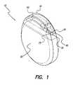
- FIG. 1is a perspective view of the implantable stimulation device showing the antenna system of the present invention
- FIG. 2is a front view of the stimulation device of FIG. 1 , showing the antenna system of the present invention
- FIG. 3is a left side view of the stimulation device of FIG. 1 , showing a left side view of the antenna system of the present invention
- FIG. 4is a top view of the stimulation device of FIG. 1 , showing the top view of the antenna system of the present invention
- FIG. 5is a schematic, block diagram of the antenna system of the present invention.
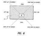
- FIG. 6is a diagram showing the various directional placements of a test receiving antenna relative to a test transmitting antenna which is located in a simulated body.
- a self-resonating, folded monopole antenna system for use in an implantable medical deviceis disclosed herein.
- the antennais intended to be used with a programmer transceiver to down-link data to the medical device or up-link telemetered data from the medical device to the programmer.
- the metal portion of the device housingis employed as a ground plane of the antenna.
- the monopole antennais folded once to conform to the periphery of the epoxy portion of the housing.
- a preferred embodiment of the antennawill be discussed in the context of use within an implantable spinal cord stimulator that is used to treat intractable pain and is intended to be implanted in a patient's abdomen.
- FIG. 1shows, in accordance with the present invention, a perspective view of an exemplary embodiment of an RF telemetry system which comprises a folded monopole antenna 60 within an implantable spinal cord stimulator 10 .
- the housingmay be comprised of two parts, a metal portion 20 and an epoxy portion 30 .
- the metal housing portion 20 of the implanted deviceis approximately a partial elliptical cylinder, having the following dimensions: a 55 millimeter major axis, a 45 millimeter minor axis and a 9 millimeter thickness.
- the metal portion of the housingdeviates from an elliptical cylinder in that a portion of the elliptical cylinder is replaced by an epoxy portion 30 .
- the epoxy portionhas openings 40 and 50 to permit stimulation leads (not shown) to be inserted through the epoxy and coupled to lead connections, which are electrically connected to stimulation circuits inside the stimulator.
- the stimulatoris preferably flat and thin to facilitate implantation under fascia, muscle and skin. All exterior edges of the stimulator are rounded to eliminate sharp edges.
- the antenna 60is shown as a thin conductive wire which can be easily conformed into a desired shape.
- the antenna shownhas a free end 65 and a connection end 75 .
- the antennacan be shaped as two separate arcs that are in planes that are substantially parallel to each other. It will be appreciated that, in addition to the conductor in the form of a wire, the conductor may be any suitable conformable, elongate configuration including a thin conductor strip having a definable first end and second end.
- the wire antennaas shown in FIG. 1 , runs along the curved outer edge within the epoxy housing 30 to maximize the separation between the metal housing and the antenna. This separation helps reduce RF transmission reception distortion and interference from the metal housing. Because the free end 65 of the antenna is not electrically connected, the antenna is effectively a folded monopole having one electrical connection at connection end 75 .
- the stimulator 10may contain a microprocessor and an electrical circuit designed to deliver stimulation pulses through the connected leads and may include sense amplifiers which can detect the lead and tissue impedance.
- the circuitmay further include memory registers or RAMS for storing a variety of programmed operating modes and parameters to shape the stimulation pulse regime. Some of these parameters include pulse-width, frequency of stimulation, monopolar or bipolar electrode configuration, pulse amplitude envelopes, and uniphasic or biphasic stimulation.
- the devicemay also collect data pertaining to patient condition.
- FIG. 2shows, in accordance with the invention, a front view of the stimulator 10 , and a folded monopole antenna 60 , within the epoxy portion 30 .
- FIGS. 3 and 4provide a left side view and top view, respectively, of the stimulator 10 showing the conformal shape of the folded antenna 60 inside the epoxy portion 30 .
- the antennahas a shape that includes two arcs which arcs are connected together on one end of each arc. It can be seen that the antenna is thereby folded in a manner to provide the longest antenna length and maximum possible separation between the antenna and the metal portion of the housing in order to minimize interference.
- FIG. 5shows a schematic block diagram of the folded monopole RF antenna system of the present invention.
- the folded monopole antenna 60has free end 65 and connection end 75 which, in the embodiment shown, is coupled to metal connection pad 67 on the internal printed circuit board 68 .
- This metal pad 67is further connected to a receiver/transmitter circuitry 69 .
- the receiver circuitsenses, amplifies and processes induced currents captured by the antenna 60 and the transmitter circuit can transmit signals back to a programmer via the same antenna.
- the receiver and transmitter circuitrycan only operate one at time. Software programming may be employed to control a switch which turns one circuit on and the other circuit off during a particular time interval. Both the receiver and transmitter circuits are connected to a common circuit ground.
- connection pad 66is also electrically connected to the metal housing acting as a ground plane.
- the metal housingas a ground plane increases the effective length of the antenna and beneficially shapes the RF radiation pattern of the antenna.
- the second metal pad 66may be alternatively attached on the inside or outside surface of the metal housing, instead of the internal printed circuit board.
- the resonant frequency of the antennadepends on the dielectric values of the epoxy and body tissue, as well as the actual length of the conductor wire within the epoxy.
- the epoxyis used to insulate the antenna from the body tissue and, as such, the epoxy must be biocompatible for long-term implantation.
- the epoxy chosenshould have a relatively high dielectric constant and exhibit low signal losses. Taking into account the choice of epoxy and the intended placement in the body, a desired resonant frequency of the antenna can be obtained by varying the length of the antenna.
- the above-described antennahas been fabricated and its properties have been measured.
- the antennaused a 78 mm long copper wire of 20 AWG. One end of the antenna was attached to the metal case and the entire antenna was embedded within an epoxy having ⁇ r ⁇ 3.6.
- the antenna's measured input impedance in airwas 18-j176. In simulated body fluids the measured input impedance was 18-j11. When pressed against the body, the antenna provided an input impedance of 19-j9 which was comparable to the results obtained in simulated body fluids.
- FIG. 6shows a diagram of a test set-up for a directional detection test in which a simulated spinal cord stimulator is implanted into the back of a patient.
- a pair of commercially available Chipcon CC1000 demonstration bread boards operating at a transmission frequency of 433 MHzwas used to determine the detection distances of a test folded monopole antenna relative to variable positions of a test transmission antenna.
- the test, folded monopole antennawas attached to the transmitter, while on the other bread board, a helical (stub) monopole antenna was attached to an external transreceiver.
- a phantom gelwas concocted to simulate the RF transmission attenuation properties of the tissue.
- the monopole antenna and batterywere connected to the test bread board and these were placed inside a polybag which, in turn, was immersed in the gel material simulating body tissue.
- the test antenna system 70was located in the simulated body tissue 71 towards the back of the simulated body.
- the transmitter outputwas set to ⁇ 15 dBm, the maximum power that would be permitted with an ideal antenna under the MICS regulation.
- the receiver RSSIreceived signal strength indicator
- An LED indicatorwas installed to illuminate at just above the detectable level for a 10 kbytes/sec FSK signal and a second LED indicator was set to illuminate at approximately 20 dB above the threshold. This threshold level was used to determine the effective frequency range. The results showed that the resonating characteristics of the antenna placed in the phantom tissue varied little between 403 and 433 MHz.
- the measured ranges for detectable transmission distance as a function of position relative to the transmitting antennaare shown in Table 1. As shown in FIG. 6 the receiving antenna was placed at various locations relative to the test transmitting antenna 70 .
- the detectable rangewas at a minimum at the front of the simulated body, as expected, since the signal travels through the simulated body to reach the receiver. Although the detectable range was at a minimum in front of the simulated body, the effective transmission distance, nevertheless, extended to a respectable 91 inches. A maximum detectable distance was achieved at the back and along the back 45° lines.
- the antennawas not impedance matched with the front-end RF circuitry of the demonstration board during the test, which may have caused loss of efficiency.
- the front end RF circuitrycan be easily designed to match the 20 ohm resistance of the antenna.
- the improved, folded monopole antennais a compact structure which does not need a separate tuning component, as this antenna is self-resonating around the frequency range centered around 403.5 MHz. Because the antenna system of the present invention requires no additional circuitry to tune the resonance frequency, scarce battery power is conserved. The antenna system achieves sufficient gain to communicate with an external transmitting antenna up to a distance of 91 inches.
Landscapes
- Health & Medical Sciences (AREA)
- Physics & Mathematics (AREA)
- Nuclear Medicine, Radiotherapy & Molecular Imaging (AREA)
- Acoustics & Sound (AREA)
- Engineering & Computer Science (AREA)
- Biomedical Technology (AREA)
- Electromagnetism (AREA)
- Radiology & Medical Imaging (AREA)
- Life Sciences & Earth Sciences (AREA)
- Animal Behavior & Ethology (AREA)
- General Health & Medical Sciences (AREA)
- Public Health (AREA)
- Veterinary Medicine (AREA)
- Electrotherapy Devices (AREA)
Abstract
Description
| TABLE 1 |
| Detection range test using a folded monopole antenna attached to a |
| transmitter and immersed in a phantom gel. A helical stub monopole |
| was the receiving antenna and the transmitter power was set at −15 dBm. |
| Position of External Receiver Rela- | Detectable Transmission Distance |
| tive to the Implantable Stimulator | (sensitivity ≈ −90 dBm) |
| Front of simulated body | 91 | in |
| Back of simulated body | 269 | in |
| Side of simulated body | 194 | in |
| Front of simulated body at 45° | 118 | in |
| Back of simulated body at 45° | 211 | in |
Claims (28)
Priority Applications (2)
| Application Number | Priority Date | Filing Date | Title |
|---|---|---|---|
| US10/615,081US7554493B1 (en) | 2002-07-08 | 2003-07-08 | Folded monopole antenna for implanted medical device |
| US12/469,810US20090240309A1 (en) | 2002-07-08 | 2009-05-21 | Folded Antenna For Implanted Medical Device |
Applications Claiming Priority (2)
| Application Number | Priority Date | Filing Date | Title |
|---|---|---|---|
| US39489102P | 2002-07-08 | 2002-07-08 | |
| US10/615,081US7554493B1 (en) | 2002-07-08 | 2003-07-08 | Folded monopole antenna for implanted medical device |
Related Child Applications (1)
| Application Number | Title | Priority Date | Filing Date |
|---|---|---|---|
| US12/469,810ContinuationUS20090240309A1 (en) | 2002-07-08 | 2009-05-21 | Folded Antenna For Implanted Medical Device |
Publications (1)
| Publication Number | Publication Date |
|---|---|
| US7554493B1true US7554493B1 (en) | 2009-06-30 |
Family
ID=40793534
Family Applications (2)
| Application Number | Title | Priority Date | Filing Date |
|---|---|---|---|
| US10/615,081Expired - Fee RelatedUS7554493B1 (en) | 2002-07-08 | 2003-07-08 | Folded monopole antenna for implanted medical device |
| US12/469,810AbandonedUS20090240309A1 (en) | 2002-07-08 | 2009-05-21 | Folded Antenna For Implanted Medical Device |
Family Applications After (1)
| Application Number | Title | Priority Date | Filing Date |
|---|---|---|---|
| US12/469,810AbandonedUS20090240309A1 (en) | 2002-07-08 | 2009-05-21 | Folded Antenna For Implanted Medical Device |
Country Status (1)
| Country | Link |
|---|---|
| US (2) | US7554493B1 (en) |
Cited By (48)
| Publication number | Priority date | Publication date | Assignee | Title |
|---|---|---|---|---|
| US20090240309A1 (en)* | 2002-07-08 | 2009-09-24 | Boston Scientific Neuromodulation Corporation | Folded Antenna For Implanted Medical Device |
| US20100019985A1 (en)* | 2008-07-24 | 2010-01-28 | Jacob Bashyam | Header with integral antenna for implantable medical devices |
| US20100082080A1 (en)* | 2008-09-30 | 2010-04-01 | Medtronic, Inc. | Telemetry antenna for an implantable medical device |
| US20100168565A1 (en)* | 2007-01-04 | 2010-07-01 | Sense A/S | System for measuring blood pressure in an artery |
| US20110022100A1 (en)* | 2009-07-21 | 2011-01-27 | Boston Scientific Neuromodulation Corporation | Multi-port modular connector for implantable electrical stimulation systems and methods of making and using |
| US20110112612A1 (en)* | 2009-11-11 | 2011-05-12 | Boston Scientific Neuromodulation Corporation | Using the Case of an Implantable Medical Device to Broaden Communication Bandwidth |
| WO2011111008A1 (en)* | 2010-03-11 | 2011-09-15 | Ecole Polytechnique Federale De Lausanne (Epfl) | Telemetry system for sensing applications in lossy media |
| US20120001812A1 (en)* | 2010-06-30 | 2012-01-05 | Medtronic, Inc. | Implantable medical device antenna |
| WO2012018546A1 (en)* | 2010-08-02 | 2012-02-09 | Spinal Modulation, Inc. | Neurostimulation programmers with improved rf antenna radiation patterns |
| US20120130206A1 (en)* | 2010-11-23 | 2012-05-24 | Sasidhar Vajha | Modular antenna for implantable medical device |
| US8849415B2 (en) | 2006-07-31 | 2014-09-30 | Boston Scientific Neuromodulation Corporation | Multi-channel connector for brain stimulation system |
| US8903497B2 (en) | 2010-09-30 | 2014-12-02 | Medtronic, Inc. | Conformal antenna for implantable medical device and implantable medical device with such antenna |
| US8929986B2 (en) | 2011-11-04 | 2015-01-06 | Nevro Corporation | Medical device communication and charging assemblies for use with implantable signal generators, and associated systems and methods |
| US9044616B2 (en) | 2010-07-01 | 2015-06-02 | Boston Scientific Neuromodulation Corporation | Charging system for an implantable medical device employing magnetic and electric fields |
| US9089712B2 (en) | 2011-04-29 | 2015-07-28 | Cyberonics, Inc. | Implantable medical device without antenna feedthrough |
| USD736383S1 (en) | 2012-11-05 | 2015-08-11 | Nevro Corporation | Implantable signal generator |
| CN105140630A (en)* | 2015-10-08 | 2015-12-09 | 邝嘉豪 | Implanted detector for medical treatment |
| US9240630B2 (en) | 2011-04-29 | 2016-01-19 | Cyberonics, Inc. | Antenna shield for an implantable medical device |
| US9259582B2 (en) | 2011-04-29 | 2016-02-16 | Cyberonics, Inc. | Slot antenna for an implantable device |
| US9265958B2 (en) | 2011-04-29 | 2016-02-23 | Cyberonics, Inc. | Implantable medical device antenna |
| EP3028740A1 (en) | 2014-12-05 | 2016-06-08 | BIOTRONIK SE & Co. KG | Antenna for an implantable medical device |
| US20160174842A1 (en)* | 2014-12-17 | 2016-06-23 | Elwha Llc | Epidermal electronics systems having radio frequency antennas systems and methods |
| US9387331B2 (en) | 2013-10-08 | 2016-07-12 | Medtronic, Inc. | Implantable medical devices having hollow cap cofire ceramic structures and methods of fabricating the same |
| US9425516B2 (en) | 2012-07-06 | 2016-08-23 | The Ohio State University | Compact dual band GNSS antenna design |
| US9502754B2 (en) | 2014-01-24 | 2016-11-22 | Medtronic, Inc. | Implantable medical devices having cofire ceramic modules and methods of fabricating the same |
| US9837704B2 (en) | 2013-03-14 | 2017-12-05 | Neuropace, Inc. | Anatomically compliant antenna for implantable medical device |
| US20180042552A1 (en)* | 2016-08-10 | 2018-02-15 | Pacesetter, Inc. | Antenna for an Implantable Cardiac Monitoring Devie |
| US9956394B2 (en) | 2015-09-10 | 2018-05-01 | Boston Scientific Neuromodulation Corporation | Connectors for electrical stimulation systems and methods of making and using |
| US10029105B2 (en) | 2013-06-07 | 2018-07-24 | Cardiac Pacemakers, Inc. | Antennas for implantable medical devices |
| US10201713B2 (en) | 2016-06-20 | 2019-02-12 | Boston Scientific Neuromodulation Corporation | Threaded connector assembly and methods of making and using the same |
| US10220215B2 (en) | 2016-03-29 | 2019-03-05 | Boston Scientific Neuromodulation Corporation | Far-field short-range radio-frequency antenna on the side of an implantable medical device case |
| US10307602B2 (en) | 2016-07-08 | 2019-06-04 | Boston Scientific Neuromodulation Corporation | Threaded connector assembly and methods of making and using the same |
| US10342983B2 (en) | 2016-01-14 | 2019-07-09 | Boston Scientific Neuromodulation Corporation | Systems and methods for making and using connector contact arrays for electrical stimulation systems |
| US10543374B2 (en) | 2016-09-30 | 2020-01-28 | Boston Scientific Neuromodulation Corporation | Connector assemblies with bending limiters for electrical stimulation systems and methods of making and using same |
| US10603499B2 (en) | 2017-04-07 | 2020-03-31 | Boston Scientific Neuromodulation Corporation | Tapered implantable lead and connector interface and methods of making and using |
| US10639485B2 (en) | 2017-09-15 | 2020-05-05 | Boston Scientific Neuromodulation Corporation | Actuatable lead connector for an operating room cable assembly and methods of making and using |
| CN111262009A (en)* | 2020-03-18 | 2020-06-09 | 苏州无双医疗设备有限公司 | An antenna and implantable medical device |
| US10814136B2 (en) | 2017-02-28 | 2020-10-27 | Boston Scientific Neuromodulation Corporation | Toolless connector for latching stimulation leads and methods of making and using |
| US10869634B2 (en) | 2016-05-13 | 2020-12-22 | Pacesetter, Inc. | Method for manufacturing implantable device header with embedded sensor and antenna |
| US10905871B2 (en) | 2017-01-27 | 2021-02-02 | Boston Scientific Neuromodulation Corporation | Lead assemblies with arrangements to confirm alignment between terminals and contacts |
| US10918873B2 (en) | 2017-07-25 | 2021-02-16 | Boston Scientific Neuromodulation Corporation | Systems and methods for making and using an enhanced connector of an electrical stimulation system |
| US11045656B2 (en) | 2017-09-15 | 2021-06-29 | Boston Scientific Neuromodulation Corporation | Biased lead connector for operating room cable assembly and methods of making and using |
| US11052259B2 (en) | 2018-05-11 | 2021-07-06 | Boston Scientific Neuromodulation Corporation | Connector assembly for an electrical stimulation system and methods of making and using |
| US11103712B2 (en) | 2018-01-16 | 2021-08-31 | Boston Scientific Neuromodulation Corporation | Connector assemblies with novel spacers for electrical stimulation systems and methods of making and using same |
| US11139603B2 (en) | 2017-10-03 | 2021-10-05 | Boston Scientific Neuromodulation Corporation | Connectors with spring contacts for electrical stimulation systems and methods of making and using same |
| US11357992B2 (en) | 2019-05-03 | 2022-06-14 | Boston Scientific Neuromodulation Corporation | Connector assembly for an electrical stimulation system and methods of making and using |
| US11844881B2 (en) | 2018-05-17 | 2023-12-19 | The Curators Of The University Of Missouri | Composite material with high dielectric constant and use in biocompatible devices |
| US12343547B2 (en) | 2021-08-19 | 2025-07-01 | Boston Scientific Neuromodulation Corporation | Connectors for an electrical stimulation system and methods of making and using |
Families Citing this family (2)
| Publication number | Priority date | Publication date | Assignee | Title |
|---|---|---|---|---|
| EP2150313B1 (en)* | 2007-04-24 | 2013-06-19 | St. Jude Medical AB | Container for storing an implantable medical device, and a method for packaging such a device |
| AU2020293073B2 (en)* | 2019-06-14 | 2023-07-27 | Boston Scientific Neuromodulation Corporation | Implantable medical device without a wire-wound coil configured to receive wireless power from an external charger |
Citations (18)
| Publication number | Priority date | Publication date | Assignee | Title |
|---|---|---|---|---|
| US4681111A (en) | 1985-04-05 | 1987-07-21 | Siemens-Pacesetter, Inc. | Analog and digital telemetry system for an implantable device |
| US5058581A (en) | 1990-02-20 | 1991-10-22 | Siemens-Pacesetter, Inc. | Telemetry apparatus and method for implantable tissue stimulator |
| US5562713A (en) | 1995-01-18 | 1996-10-08 | Pacesetter, Inc. | Bidirectional telemetry apparatus and method for implantable device |
| US5861019A (en) | 1997-07-25 | 1999-01-19 | Medtronic Inc. | Implantable medical device microstrip telemetry antenna |
| US5912648A (en) | 1996-11-07 | 1999-06-15 | Motorola, Inc. | Compact patch antenna |
| US6008762A (en) | 1997-03-31 | 1999-12-28 | Qualcomm Incorporated | Folded quarter-wave patch antenna |
| US6054955A (en) | 1993-08-23 | 2000-04-25 | Apple Computer, Inc. | Folded monopole antenna for use with portable communications devices |
| US6133890A (en) | 1999-03-02 | 2000-10-17 | Damiani; Sylvio Mauro | Self-resonant folded unipole antenna |
| US6147652A (en)* | 1997-09-19 | 2000-11-14 | Kabushiki Kaisha Toshiba | Antenna apparatus |
| US6218992B1 (en) | 2000-02-24 | 2001-04-17 | Ericsson Inc. | Compact, broadband inverted-F antennas with conductive elements and wireless communicators incorporating same |
| US6240317B1 (en)* | 1999-04-30 | 2001-05-29 | Medtronic, Inc. | Telemetry system for implantable medical devices |
| US6259418B1 (en) | 2000-01-20 | 2001-07-10 | 3Com Corp. | Modified monopole antenna |
| US6285336B1 (en) | 1999-11-03 | 2001-09-04 | Andrew Corporation | Folded dipole antenna |
| US6317099B1 (en) | 2000-01-10 | 2001-11-13 | Andrew Corporation | Folded dipole antenna |
| EP1166820A2 (en) | 2000-06-19 | 2002-01-02 | Medtronic, Inc. | Implantable medical device with external recharging coil |
| US6342857B1 (en) | 2000-09-01 | 2002-01-29 | Auden Techno Corp. | Broadband circuit shorted resonant patch antenna |
| US6379300B1 (en) | 1999-10-08 | 2002-04-30 | Medtronic, Inc. | Telemtry system for implantable medical devices |
| US6456256B1 (en)* | 2001-08-03 | 2002-09-24 | Cardiac Pacemakers, Inc. | Circumferential antenna for an implantable medical device |
Family Cites Families (13)
| Publication number | Priority date | Publication date | Assignee | Title |
|---|---|---|---|---|
| US4127110A (en)* | 1976-05-24 | 1978-11-28 | Huntington Institute Of Applied Medical Research | Implantable pressure transducer |
| US5342408A (en)* | 1993-01-07 | 1994-08-30 | Incontrol, Inc. | Telemetry system for an implantable cardiac device |
| DE29711698U1 (en)* | 1997-07-03 | 1997-09-04 | Dosch & Amand GmbH & Co. KG, 81927 München | Communication plug-in card |
| US5995052A (en)* | 1998-05-15 | 1999-11-30 | Ericsson Inc. | Flip open antenna for a communication device |
| FI19992267A7 (en)* | 1999-10-20 | 2001-06-11 | Nokia Mobile Phones Ltd | Expansion card for wireless communication and its antenna structure |
| US7309262B2 (en)* | 2000-06-20 | 2007-12-18 | Medtronic, Inc. | Connector assembly for an implantable medical device and process for making |
| US7089059B1 (en)* | 2000-11-03 | 2006-08-08 | Pless Benjamin D | Predicting susceptibility to neurological dysfunction based on measured neural electrophysiology |
| US6603432B2 (en)* | 2001-02-23 | 2003-08-05 | Tyco Electronics Logistics Ag | Low profile dual-band conformal antenna |
| US7554493B1 (en)* | 2002-07-08 | 2009-06-30 | Boston Scientific Neuromodulation Corporation | Folded monopole antenna for implanted medical device |
| US6664931B1 (en)* | 2002-07-23 | 2003-12-16 | Motorola, Inc. | Multi-frequency slot antenna apparatus |
| US7289855B2 (en)* | 2004-06-09 | 2007-10-30 | Medtronic, Inc. | Implantable medical device package antenna |
| US20070060955A1 (en)* | 2004-06-10 | 2007-03-15 | Ndi Medical, Llc | Implantable pulse generator systems and methods for providing functional and/or therapeutic stimulation of muscles and/or nerves and/or central nervous system tissue |
| US20060122665A1 (en)* | 2004-12-02 | 2006-06-08 | David Nghiem | Compact conformal antenna for an implanted medical device telemetry system |
- 2003
- 2003-07-08USUS10/615,081patent/US7554493B1/ennot_activeExpired - Fee Related
- 2009
- 2009-05-21USUS12/469,810patent/US20090240309A1/ennot_activeAbandoned
Patent Citations (18)
| Publication number | Priority date | Publication date | Assignee | Title |
|---|---|---|---|---|
| US4681111A (en) | 1985-04-05 | 1987-07-21 | Siemens-Pacesetter, Inc. | Analog and digital telemetry system for an implantable device |
| US5058581A (en) | 1990-02-20 | 1991-10-22 | Siemens-Pacesetter, Inc. | Telemetry apparatus and method for implantable tissue stimulator |
| US6054955A (en) | 1993-08-23 | 2000-04-25 | Apple Computer, Inc. | Folded monopole antenna for use with portable communications devices |
| US5562713A (en) | 1995-01-18 | 1996-10-08 | Pacesetter, Inc. | Bidirectional telemetry apparatus and method for implantable device |
| US5912648A (en) | 1996-11-07 | 1999-06-15 | Motorola, Inc. | Compact patch antenna |
| US6008762A (en) | 1997-03-31 | 1999-12-28 | Qualcomm Incorporated | Folded quarter-wave patch antenna |
| US5861019A (en) | 1997-07-25 | 1999-01-19 | Medtronic Inc. | Implantable medical device microstrip telemetry antenna |
| US6147652A (en)* | 1997-09-19 | 2000-11-14 | Kabushiki Kaisha Toshiba | Antenna apparatus |
| US6133890A (en) | 1999-03-02 | 2000-10-17 | Damiani; Sylvio Mauro | Self-resonant folded unipole antenna |
| US6240317B1 (en)* | 1999-04-30 | 2001-05-29 | Medtronic, Inc. | Telemetry system for implantable medical devices |
| US6379300B1 (en) | 1999-10-08 | 2002-04-30 | Medtronic, Inc. | Telemtry system for implantable medical devices |
| US6285336B1 (en) | 1999-11-03 | 2001-09-04 | Andrew Corporation | Folded dipole antenna |
| US6317099B1 (en) | 2000-01-10 | 2001-11-13 | Andrew Corporation | Folded dipole antenna |
| US6259418B1 (en) | 2000-01-20 | 2001-07-10 | 3Com Corp. | Modified monopole antenna |
| US6218992B1 (en) | 2000-02-24 | 2001-04-17 | Ericsson Inc. | Compact, broadband inverted-F antennas with conductive elements and wireless communicators incorporating same |
| EP1166820A2 (en) | 2000-06-19 | 2002-01-02 | Medtronic, Inc. | Implantable medical device with external recharging coil |
| US6342857B1 (en) | 2000-09-01 | 2002-01-29 | Auden Techno Corp. | Broadband circuit shorted resonant patch antenna |
| US6456256B1 (en)* | 2001-08-03 | 2002-09-24 | Cardiac Pacemakers, Inc. | Circumferential antenna for an implantable medical device |
Cited By (72)
| Publication number | Priority date | Publication date | Assignee | Title |
|---|---|---|---|---|
| US20090240309A1 (en)* | 2002-07-08 | 2009-09-24 | Boston Scientific Neuromodulation Corporation | Folded Antenna For Implanted Medical Device |
| US8849415B2 (en) | 2006-07-31 | 2014-09-30 | Boston Scientific Neuromodulation Corporation | Multi-channel connector for brain stimulation system |
| US20100168565A1 (en)* | 2007-01-04 | 2010-07-01 | Sense A/S | System for measuring blood pressure in an artery |
| US20100019985A1 (en)* | 2008-07-24 | 2010-01-28 | Jacob Bashyam | Header with integral antenna for implantable medical devices |
| US8219204B2 (en) | 2008-09-30 | 2012-07-10 | Medtronic, Inc. | Telemetry antenna for an implantable medical device |
| US20100082080A1 (en)* | 2008-09-30 | 2010-04-01 | Medtronic, Inc. | Telemetry antenna for an implantable medical device |
| US20110022100A1 (en)* | 2009-07-21 | 2011-01-27 | Boston Scientific Neuromodulation Corporation | Multi-port modular connector for implantable electrical stimulation systems and methods of making and using |
| US8600507B2 (en) | 2009-07-21 | 2013-12-03 | Boston Scientific Neuromodulation Corporation | Multi-port modular connector for implantable electrical stimulation systems and methods of making and using |
| US20110112612A1 (en)* | 2009-11-11 | 2011-05-12 | Boston Scientific Neuromodulation Corporation | Using the Case of an Implantable Medical Device to Broaden Communication Bandwidth |
| US8457756B2 (en) | 2009-11-11 | 2013-06-04 | Boston Scientific Neuromodulation Corporation | Using the case of an implantable medical device to broaden communication bandwidth |
| US9061159B2 (en) | 2009-11-11 | 2015-06-23 | Boston Scientific Neuromodulation Corporation | Using the case of an implantable medical device to broaden communication bandwidth |
| WO2011111008A1 (en)* | 2010-03-11 | 2011-09-15 | Ecole Polytechnique Federale De Lausanne (Epfl) | Telemetry system for sensing applications in lossy media |
| US20120001812A1 (en)* | 2010-06-30 | 2012-01-05 | Medtronic, Inc. | Implantable medical device antenna |
| US8620449B2 (en)* | 2010-06-30 | 2013-12-31 | Medtronic, Inc. | Implantable medical device antenna |
| US9211416B2 (en) | 2010-07-01 | 2015-12-15 | Boston Scientific Neuromodulation Corporation | Charging system for an implantable medical device employing magnetic and electric fields |
| US9044616B2 (en) | 2010-07-01 | 2015-06-02 | Boston Scientific Neuromodulation Corporation | Charging system for an implantable medical device employing magnetic and electric fields |
| US9427591B2 (en) | 2010-07-01 | 2016-08-30 | Boston Scientific Neuromodulation Corporation | Charging system for an implantable medical device employing magnetic and electric fields |
| US9265957B2 (en) | 2010-07-01 | 2016-02-23 | Boston Scientific Neuromodulation Corporation | Implantable medical device and charging system employing electric fields |
| US9750945B2 (en) | 2010-08-02 | 2017-09-05 | St. Jude Medical Luxembourg Holdings SMI S.A.R.L. | Neurostimulation programmers with improved RF antenna radiation patterns |
| WO2012018546A1 (en)* | 2010-08-02 | 2012-02-09 | Spinal Modulation, Inc. | Neurostimulation programmers with improved rf antenna radiation patterns |
| US8903497B2 (en) | 2010-09-30 | 2014-12-02 | Medtronic, Inc. | Conformal antenna for implantable medical device and implantable medical device with such antenna |
| US9579509B2 (en)* | 2010-11-23 | 2017-02-28 | Cardiac Pacemakers, Inc. | Modular antenna for implantable medical device |
| US10099059B2 (en)* | 2010-11-23 | 2018-10-16 | Cardiac Pacemakers, Inc. | Modular antenna for implantable medical device |
| US20150357704A1 (en)* | 2010-11-23 | 2015-12-10 | Cardiac Pacemakers, Inc. | Modular antenna for implantable medical device |
| US10004908B2 (en) | 2010-11-23 | 2018-06-26 | Cardiac Pacemakers, Inc. | Folded antennas for implantable medical devices |
| US20120130206A1 (en)* | 2010-11-23 | 2012-05-24 | Sasidhar Vajha | Modular antenna for implantable medical device |
| US9240630B2 (en) | 2011-04-29 | 2016-01-19 | Cyberonics, Inc. | Antenna shield for an implantable medical device |
| US9265958B2 (en) | 2011-04-29 | 2016-02-23 | Cyberonics, Inc. | Implantable medical device antenna |
| US9259582B2 (en) | 2011-04-29 | 2016-02-16 | Cyberonics, Inc. | Slot antenna for an implantable device |
| US9089712B2 (en) | 2011-04-29 | 2015-07-28 | Cyberonics, Inc. | Implantable medical device without antenna feedthrough |
| US12377271B2 (en) | 2011-11-04 | 2025-08-05 | Nevro Corp. | Medical device communication and charging assemblies for use with implantable signal generators, and associated systems and methods |
| US10918866B2 (en) | 2011-11-04 | 2021-02-16 | Nevro Corp. | Medical device communication and charging assemblies for use with implantable signal generators, and associated systems and methods |
| US9776002B2 (en) | 2011-11-04 | 2017-10-03 | Nevro Corp. | Medical device communication and charging assemblies for use with implantable signal generators, and associated systems and methods |
| US8929986B2 (en) | 2011-11-04 | 2015-01-06 | Nevro Corporation | Medical device communication and charging assemblies for use with implantable signal generators, and associated systems and methods |
| US9425516B2 (en) | 2012-07-06 | 2016-08-23 | The Ohio State University | Compact dual band GNSS antenna design |
| USD736383S1 (en) | 2012-11-05 | 2015-08-11 | Nevro Corporation | Implantable signal generator |
| USD736930S1 (en) | 2012-11-05 | 2015-08-18 | Nevro Corporation | Implantable signal generator |
| US10193217B2 (en) | 2013-03-14 | 2019-01-29 | Neuropace, Inc. | Anatomically compliant antenna for implantable medical device |
| US10014571B2 (en) | 2013-03-14 | 2018-07-03 | Neuropace, Inc. | Anatomically compliant antenna for implantable medical device |
| US9837704B2 (en) | 2013-03-14 | 2017-12-05 | Neuropace, Inc. | Anatomically compliant antenna for implantable medical device |
| US10029105B2 (en) | 2013-06-07 | 2018-07-24 | Cardiac Pacemakers, Inc. | Antennas for implantable medical devices |
| US9387331B2 (en) | 2013-10-08 | 2016-07-12 | Medtronic, Inc. | Implantable medical devices having hollow cap cofire ceramic structures and methods of fabricating the same |
| US9387332B2 (en) | 2013-10-08 | 2016-07-12 | Medtronic, Inc. | Implantable medical devices having hollow sleeve cofire ceramic structures and methods of fabricating the same |
| US9502754B2 (en) | 2014-01-24 | 2016-11-22 | Medtronic, Inc. | Implantable medical devices having cofire ceramic modules and methods of fabricating the same |
| US9905916B2 (en) | 2014-12-05 | 2018-02-27 | Biotronik Se & Co. Kg | Antenna and implantable medical device |
| EP3028740A1 (en) | 2014-12-05 | 2016-06-08 | BIOTRONIK SE & Co. KG | Antenna for an implantable medical device |
| US20160174842A1 (en)* | 2014-12-17 | 2016-06-23 | Elwha Llc | Epidermal electronics systems having radio frequency antennas systems and methods |
| US9956394B2 (en) | 2015-09-10 | 2018-05-01 | Boston Scientific Neuromodulation Corporation | Connectors for electrical stimulation systems and methods of making and using |
| CN105140630A (en)* | 2015-10-08 | 2015-12-09 | 邝嘉豪 | Implanted detector for medical treatment |
| US10342983B2 (en) | 2016-01-14 | 2019-07-09 | Boston Scientific Neuromodulation Corporation | Systems and methods for making and using connector contact arrays for electrical stimulation systems |
| US10220215B2 (en) | 2016-03-29 | 2019-03-05 | Boston Scientific Neuromodulation Corporation | Far-field short-range radio-frequency antenna on the side of an implantable medical device case |
| US10869634B2 (en) | 2016-05-13 | 2020-12-22 | Pacesetter, Inc. | Method for manufacturing implantable device header with embedded sensor and antenna |
| US10201713B2 (en) | 2016-06-20 | 2019-02-12 | Boston Scientific Neuromodulation Corporation | Threaded connector assembly and methods of making and using the same |
| US10307602B2 (en) | 2016-07-08 | 2019-06-04 | Boston Scientific Neuromodulation Corporation | Threaded connector assembly and methods of making and using the same |
| US10779767B2 (en)* | 2016-08-10 | 2020-09-22 | Pacesetter, Inc. | Antenna for an implantable cardiac monitoring device |
| US20180042552A1 (en)* | 2016-08-10 | 2018-02-15 | Pacesetter, Inc. | Antenna for an Implantable Cardiac Monitoring Devie |
| US10543374B2 (en) | 2016-09-30 | 2020-01-28 | Boston Scientific Neuromodulation Corporation | Connector assemblies with bending limiters for electrical stimulation systems and methods of making and using same |
| US10905871B2 (en) | 2017-01-27 | 2021-02-02 | Boston Scientific Neuromodulation Corporation | Lead assemblies with arrangements to confirm alignment between terminals and contacts |
| US10814136B2 (en) | 2017-02-28 | 2020-10-27 | Boston Scientific Neuromodulation Corporation | Toolless connector for latching stimulation leads and methods of making and using |
| US10603499B2 (en) | 2017-04-07 | 2020-03-31 | Boston Scientific Neuromodulation Corporation | Tapered implantable lead and connector interface and methods of making and using |
| US10918873B2 (en) | 2017-07-25 | 2021-02-16 | Boston Scientific Neuromodulation Corporation | Systems and methods for making and using an enhanced connector of an electrical stimulation system |
| US10639485B2 (en) | 2017-09-15 | 2020-05-05 | Boston Scientific Neuromodulation Corporation | Actuatable lead connector for an operating room cable assembly and methods of making and using |
| US11045656B2 (en) | 2017-09-15 | 2021-06-29 | Boston Scientific Neuromodulation Corporation | Biased lead connector for operating room cable assembly and methods of making and using |
| US11951317B2 (en) | 2017-09-15 | 2024-04-09 | Boston Scientific Neuromodulation Corporation | Biased lead connector for operating room cable assembly and methods of making and using |
| US11139603B2 (en) | 2017-10-03 | 2021-10-05 | Boston Scientific Neuromodulation Corporation | Connectors with spring contacts for electrical stimulation systems and methods of making and using same |
| US11103712B2 (en) | 2018-01-16 | 2021-08-31 | Boston Scientific Neuromodulation Corporation | Connector assemblies with novel spacers for electrical stimulation systems and methods of making and using same |
| US11052259B2 (en) | 2018-05-11 | 2021-07-06 | Boston Scientific Neuromodulation Corporation | Connector assembly for an electrical stimulation system and methods of making and using |
| US11844881B2 (en) | 2018-05-17 | 2023-12-19 | The Curators Of The University Of Missouri | Composite material with high dielectric constant and use in biocompatible devices |
| US11357992B2 (en) | 2019-05-03 | 2022-06-14 | Boston Scientific Neuromodulation Corporation | Connector assembly for an electrical stimulation system and methods of making and using |
| US11612755B2 (en) | 2019-05-03 | 2023-03-28 | Boston Scientific Neuromodulation Corporation | Connector assembly for an electrical stimulation system and methods of making and using |
| CN111262009A (en)* | 2020-03-18 | 2020-06-09 | 苏州无双医疗设备有限公司 | An antenna and implantable medical device |
| US12343547B2 (en) | 2021-08-19 | 2025-07-01 | Boston Scientific Neuromodulation Corporation | Connectors for an electrical stimulation system and methods of making and using |
Also Published As
| Publication number | Publication date |
|---|---|
| US20090240309A1 (en) | 2009-09-24 |
Similar Documents
| Publication | Publication Date | Title |
|---|---|---|
| US7554493B1 (en) | Folded monopole antenna for implanted medical device | |
| US6614406B2 (en) | Circumferential antenna for an implantable medical device | |
| US7047076B1 (en) | Inverted-F antenna configuration for an implantable medical device | |
| US8301261B2 (en) | Implanted antenna and radio communications link | |
| US20080021522A1 (en) | Telemetry antennas for implantable medical devices | |
| US7467014B2 (en) | Compact and conformal telemetry antennas for implantable medical devices | |
| US8588924B2 (en) | Loaded RF antenna for implantable device | |
| US6708065B2 (en) | Antenna for an implantable medical device | |
| US7720544B2 (en) | Systems for enabling telemetry in an implantable medical device | |
| US7016733B2 (en) | Telemetry antenna for an implantable medical device | |
| US6574510B2 (en) | Telemetry apparatus and method for an implantable medical device | |
| US7313441B2 (en) | Split-can dipole antenna for an implantable medical device | |
| US8369961B2 (en) | Multi-antenna for an implantable medical device | |
| US7319901B2 (en) | Optional telemetry antenna for implantable medical devices | |
| US20030216793A1 (en) | Implantable antenna for use with an implantable medical device | |
| AU2004240245A1 (en) | An implanted antenna and radio communications link |
Legal Events
| Date | Code | Title | Description |
|---|---|---|---|
| AS | Assignment | Owner name:ADVANCED BIONICS CORPORATION, CALIFORNIA Free format text:ASSIGNMENT OF ASSIGNORS INTEREST;ASSIGNOR:RAHMAN, M. MIZANUR;REEL/FRAME:015140/0284 Effective date:20040914 | |
| AS | Assignment | Owner name:BOSTON SCIENTIFIC NEUROMODULATION CORPORATION, CAL Free format text:CHANGE OF NAME;ASSIGNOR:ADVANCED BIONICS CORPORATION;REEL/FRAME:020296/0477 Effective date:20071116 Owner name:BOSTON SCIENTIFIC NEUROMODULATION CORPORATION, CALIFORNIA Free format text:CHANGE OF NAME;ASSIGNOR:ADVANCED BIONICS CORPORATION;REEL/FRAME:020296/0477 Effective date:20071116 Owner name:BOSTON SCIENTIFIC NEUROMODULATION CORPORATION,CALI Free format text:CHANGE OF NAME;ASSIGNOR:ADVANCED BIONICS CORPORATION;REEL/FRAME:020296/0477 Effective date:20071116 | |
| FEPP | Fee payment procedure | Free format text:PAYOR NUMBER ASSIGNED (ORIGINAL EVENT CODE: ASPN); ENTITY STATUS OF PATENT OWNER: LARGE ENTITY Free format text:PAYER NUMBER DE-ASSIGNED (ORIGINAL EVENT CODE: RMPN); ENTITY STATUS OF PATENT OWNER: LARGE ENTITY | |
| STCF | Information on status: patent grant | Free format text:PATENTED CASE | |
| FPAY | Fee payment | Year of fee payment:4 | |
| FPAY | Fee payment | Year of fee payment:8 | |
| FEPP | Fee payment procedure | Free format text:MAINTENANCE FEE REMINDER MAILED (ORIGINAL EVENT CODE: REM.); ENTITY STATUS OF PATENT OWNER: LARGE ENTITY | |
| LAPS | Lapse for failure to pay maintenance fees | Free format text:PATENT EXPIRED FOR FAILURE TO PAY MAINTENANCE FEES (ORIGINAL EVENT CODE: EXP.); ENTITY STATUS OF PATENT OWNER: LARGE ENTITY | |
| STCH | Information on status: patent discontinuation | Free format text:PATENT EXPIRED DUE TO NONPAYMENT OF MAINTENANCE FEES UNDER 37 CFR 1.362 | |
| FP | Lapsed due to failure to pay maintenance fee | Effective date:20210630 |