US7554316B2 - Controlling inductive power transfer systems - Google Patents
Controlling inductive power transfer systemsDownload PDFInfo
- Publication number
- US7554316B2 US7554316B2US11/569,029US56902905AUS7554316B2US 7554316 B2US7554316 B2US 7554316B2US 56902905 AUS56902905 AUS 56902905AUS 7554316 B2US7554316 B2US 7554316B2
- Authority
- US
- United States
- Prior art keywords
- unit
- primary
- secondary device
- primary unit
- operable
- Prior art date
- Legal status (The legal status is an assumption and is not a legal conclusion. Google has not performed a legal analysis and makes no representation as to the accuracy of the status listed.)
- Active, expires
Links
Images


Classifications
- H—ELECTRICITY
- H02—GENERATION; CONVERSION OR DISTRIBUTION OF ELECTRIC POWER
- H02H—EMERGENCY PROTECTIVE CIRCUIT ARRANGEMENTS
- H02H3/00—Emergency protective circuit arrangements for automatic disconnection directly responsive to an undesired change from normal electric working condition with or without subsequent reconnection ; integrated protection
- H02H3/12—Emergency protective circuit arrangements for automatic disconnection directly responsive to an undesired change from normal electric working condition with or without subsequent reconnection ; integrated protection responsive to underload or no-load
- H—ELECTRICITY
- H02—GENERATION; CONVERSION OR DISTRIBUTION OF ELECTRIC POWER
- H02J—CIRCUIT ARRANGEMENTS OR SYSTEMS FOR SUPPLYING OR DISTRIBUTING ELECTRIC POWER; SYSTEMS FOR STORING ELECTRIC ENERGY
- H02J7/00—Circuit arrangements for charging or depolarising batteries or for supplying loads from batteries
- H02J7/0029—Circuit arrangements for charging or depolarising batteries or for supplying loads from batteries with safety or protection devices or circuits
- H02J7/00302—Overcharge protection
- H—ELECTRICITY
- H02—GENERATION; CONVERSION OR DISTRIBUTION OF ELECTRIC POWER
- H02H—EMERGENCY PROTECTIVE CIRCUIT ARRANGEMENTS
- H02H3/00—Emergency protective circuit arrangements for automatic disconnection directly responsive to an undesired change from normal electric working condition with or without subsequent reconnection ; integrated protection
- H02H3/44—Emergency protective circuit arrangements for automatic disconnection directly responsive to an undesired change from normal electric working condition with or without subsequent reconnection ; integrated protection responsive to the rate of change of electrical quantities
- H02J5/005—
- H—ELECTRICITY
- H02—GENERATION; CONVERSION OR DISTRIBUTION OF ELECTRIC POWER
- H02J—CIRCUIT ARRANGEMENTS OR SYSTEMS FOR SUPPLYING OR DISTRIBUTING ELECTRIC POWER; SYSTEMS FOR STORING ELECTRIC ENERGY
- H02J50/00—Circuit arrangements or systems for wireless supply or distribution of electric power
- H02J50/10—Circuit arrangements or systems for wireless supply or distribution of electric power using inductive coupling
- H02J50/12—Circuit arrangements or systems for wireless supply or distribution of electric power using inductive coupling of the resonant type
- H—ELECTRICITY
- H02—GENERATION; CONVERSION OR DISTRIBUTION OF ELECTRIC POWER
- H02J—CIRCUIT ARRANGEMENTS OR SYSTEMS FOR SUPPLYING OR DISTRIBUTING ELECTRIC POWER; SYSTEMS FOR STORING ELECTRIC ENERGY
- H02J50/00—Circuit arrangements or systems for wireless supply or distribution of electric power
- H02J50/40—Circuit arrangements or systems for wireless supply or distribution of electric power using two or more transmitting or receiving devices
- H—ELECTRICITY
- H02—GENERATION; CONVERSION OR DISTRIBUTION OF ELECTRIC POWER
- H02J—CIRCUIT ARRANGEMENTS OR SYSTEMS FOR SUPPLYING OR DISTRIBUTING ELECTRIC POWER; SYSTEMS FOR STORING ELECTRIC ENERGY
- H02J50/00—Circuit arrangements or systems for wireless supply or distribution of electric power
- H02J50/60—Circuit arrangements or systems for wireless supply or distribution of electric power responsive to the presence of foreign objects, e.g. detection of living beings
- H—ELECTRICITY
- H02—GENERATION; CONVERSION OR DISTRIBUTION OF ELECTRIC POWER
- H02J—CIRCUIT ARRANGEMENTS OR SYSTEMS FOR SUPPLYING OR DISTRIBUTING ELECTRIC POWER; SYSTEMS FOR STORING ELECTRIC ENERGY
- H02J50/00—Circuit arrangements or systems for wireless supply or distribution of electric power
- H02J50/80—Circuit arrangements or systems for wireless supply or distribution of electric power involving the exchange of data, concerning supply or distribution of electric power, between transmitting devices and receiving devices
- H—ELECTRICITY
- H02—GENERATION; CONVERSION OR DISTRIBUTION OF ELECTRIC POWER
- H02J—CIRCUIT ARRANGEMENTS OR SYSTEMS FOR SUPPLYING OR DISTRIBUTING ELECTRIC POWER; SYSTEMS FOR STORING ELECTRIC ENERGY
- H02J7/00—Circuit arrangements for charging or depolarising batteries or for supplying loads from batteries
- H02J7/0029—Circuit arrangements for charging or depolarising batteries or for supplying loads from batteries with safety or protection devices or circuits
- H—ELECTRICITY
- H04—ELECTRIC COMMUNICATION TECHNIQUE
- H04B—TRANSMISSION
- H04B5/00—Near-field transmission systems, e.g. inductive or capacitive transmission systems
- H04B5/70—Near-field transmission systems, e.g. inductive or capacitive transmission systems specially adapted for specific purposes
- H04B5/79—Near-field transmission systems, e.g. inductive or capacitive transmission systems specially adapted for specific purposes for data transfer in combination with power transfer
Definitions
- the present inventionrelates to controlling inductive power transfer systems for use, for example, to power portable electrical or electronic devices.
- Inductive power transfer systems suitable for powering portable devicesmay consist of two parts:
- the secondary devicesupplies the transferred power to an external load
- the secondary devicemay be carried in or by a host object which includes the load.
- the host objectmay be a portable electrical or electronic device having a rechargeable battery or cell.
- the loadmay be a battery charger circuit for charging the battery or cell.
- the secondary devicemay be incorporated in such a rechargeable cell or battery, together with a suitable battery charger circuit.
- a class of such an inductive power transfer systemsis described in our United Kingdom patent publication GB-A-2388716.
- a notable characteristic of this class of systemsis the physically “open” nature of the magnetic system of the primary unit—a significant part of the magnetic path is through air. This is necessary in order that the primary unit can supply power to different shapes and sizes of secondary device, and to multiple secondary devices simultaneously.
- Another example of such an “open” systemis described in GB-A-2389720.
- a first problemis that the primary unit cannot be 100% efficient. For example, switching losses in the electronics and I 2 R losses in the primary coil dissipate power even when there is no secondary device present, or when no secondary devices that are present require charge. This wastes energy. Preferably the primary unit should enter a low-power “standby mode” in this situation.
- a second problem in such systemsis that it is not possible to mechanically prevent foreign objects from being placed into proximity with the primary coil, coupling to the coil. Foreign objects made of metal will have eddy-currents induced therein. These eddy currents tend to act to exclude the flux, but because the material has resistance, the flowing eddy currents will suffer I 2 R losses which will cause heating of the object. There are two particular cases where this heating may be significant:
- parasitic loadssuch foreign objects that cause power drain are termed “parasitic loads”.
- the primary unitshould enter a “shutdown mode” when parasitic loads are present, to avoid heating them.
- Solutions to the first problem, of not wasting power when no secondary device requires chargeinclude:
- an inductive power transfer systemcomprising a primary unit, having a primary coil and electrical drive means connected to the primary coil for applying electrical drive signals thereto so as to generate an electromagnetic field, and the system also comprising at least one secondary device, separable from the primary unit and having a secondary coil adapted to couple with said field when the secondary device is in proximity to the primary unit so that power can be transferred inductively from the primary unit to the secondary device without direct electrical conductive contacts therebetween, wherein the primary unit further comprises: control means operable to cause a circuit including said primary coil to operate, during a measurement period, in an undriven resonating condition in which the application of said drive signals to said primary coil by said electrical drive means is suspended so that energy stored in said circuit decays over a course of said period; and decay measurement means operable to take one or more measures of such energy decay during said period; said control means being further operable, in dependence upon said one or more energy decay measures, to control the electrical drive means so as to restrict or stop inductive power transfer
- Such a systemis advantageous because it can address either or both the standby problem and the parasitic load detection problem listed above, in a robust and cost-effective manner, and is particularly advantageous in systems which may have multiple secondary devices present in different charge states, and/or whose open magnetic nature makes it easy for parasitic objects to couple to the primary coil.
- ring-downwill be used to mean causing the circuit (“resonant tank”) including the primary coil to operate in this undriven resonating condition.
- the or one energy decay measureis a measure of a rate of such energy decay.
- the rate of energy decayis a measure of the rate at which energy is being removed from the resonant tank.
- the control meansmay employ the energy decay measures to detect when a substantial parasitic load is present in proximity to said primary unit, and restrict or stop inductive power transfer from the primary unit following the detection of such a substantial parasitic load. For example, the energy decay rate may be compared with a shutdown threshold, and if the rate exceeds the threshold the power transfer is shut down.
- control meansmay employ the energy decay measures to detect when there is no secondary device present in proximity to the primary unit, and restrict or stop inductive power transfer from the primary unit when no such secondary device is detected.
- control meansmay employ first compensation information relating to a load imposed on the primary unit by losses in the primary unit itself so as to compensate for said losses of said primary unit. This prevents the detection from being affected by the inefficiencies in the primary coil itself and any other components of the resonant tank, as mentioned above.
- the primary unitmay further comprise calibration means for deriving part or all of the first compensation information from measurements taken by the primary unit when it is effectively in electromagnetic isolation.
- the secondary devicemay suffer magnetic losses intrinsic to its construction, for example in magnetic core material, and other metal used in its construction.
- These so-called “friendly parasitics”will be accounted for by the primary unit as a further parasitic loss, and if they sum to more than the threshold, the control means will shut the primary unit down. This may be avoided by providing a method of communicating the friendly parasitics of a device to the primary unit so that they may be accounted for and added to the shutdown threshold.
- said control meansmay employ second compensation information relating to a parasitic load imposed on the primary unit by the secondary device so as to compensate for the parasitic load of the secondary device.
- the or each secondary deviceis operable to communicate its second compensation information directly to the primary unit or to communicate to the primary unit other information from which the primary unit can derive the second compensation information.
- the secondary devicemay modulate a dummy load to communicate this other information, and the primary unit may derive the second compensation information by measuring the dummy load modulation.
- One way of doing thisis to have a feedback resistor, whose value is proportional to the value of the friendly parasitics of the secondary device, which can be switched across the secondary coil, creating a dummy parasitic load. If this feedback resistor is always applied during certain ring-downs (for example during the third ring-down of a set), the primary unit can then measure the sum of the incremental loads resulting from the feedback resistors in each secondary device present (whether its load is drawing power or not) and adjust its threshold accordingly. As described below, the same feedback resistor may be used as a binary on/off signalling means to control standby mode.
- Part or all of the first compensation information and/or part or all of the second compensation informationmay be information stored in the primary unit during manufacture and/or testing of the primary unit.
- the systemmay have information varying means for varying one or both of the first and second compensation information when one or more operating conditions (for example, temperature) of the primary unit vary.
- the decay measurement meansmay take one or more first such energy decay measures in a first such measurement period and take one or more second such energy decay measures in a second measurement period.
- the secondary devicemay comprise decay varying means which cause the secondary device to consume more energy in the first measurement period than in the second measurement period.
- the control means in said primary unitcan then employ the first and second energy decay measures to detect when a secondary device of the system is present in proximity to the primary unit. For example, if the control means detects a substantial difference between the first energy measures and the second energy measures, it may conclude that a secondary device must be present.
- the decay varying meansmay cause the secondary device to impose a first dummy load on the primary unit in the first measurement period and to impose a second dummy load, different from the first dummy load, on said primary unit in the second measurement period.
- One of the first and second dummy loadsmay be zero.
- the secondary devicemay apply an additional dummy (or “feedback”) load only during some ring-downs and not during others, or only during some part of the ring-down but not others. This may be done for example by switching the feedback resistor mentioned above across the secondary coil, creating a dummy parasitic load, as measured by the primary unit, which varies with time. In contrast, true parasitic loads (for example a piece of steel) will appear to be a constant parasitic load. If the primary unit control means takes similar load measurements between different ring-downs, or different parts of the same ring-down, it may put the drive means into a power-saving “standby” mode. This mode will be entered when no valid secondary device is present.
- the decay varying meansmay be disabled when an actual load of the secondary device requires no power. If the secondary device only presents a time-varying load during ring-down when it requires power, then the primary unit will enter a standby mode even when there are secondary devices present, if they don't require power.
- a difference between the first dummy load and the second dummy loadmay be set in dependence upon said parasitic load imposed on said primary unit by said secondary device. This is a convenient way to communicate the second compensation information to the primary unit.
- the secondary devicemay be adapted to supply the power it receives inductively from the primary unit to an actual load external to the secondary device.
- the loadmay be physically separable from the rest of the secondary device, for example it may be connected by a removable plug and socket arrangement.
- the secondary devicewill generally include its own circuitry which will need some of the received power too. In some cases the load could be internal to the secondary device.
- the secondary devicepreferably comprises a storage means for storing energy received from the primary unit.
- the storage meanswhere provided, supplies stored energy to the actual load and/or circuitry of the secondary device when the circuit is operating in the undriven resonating condition. This is not essential in all embodiments. Any load which can cope with short power reductions or interruptions will not require the storage means.
- the secondary devicemay comprise load isolation means operable during the measurement period to prevent the supply to an actual load of the secondary device of any of the power being received inductively by the secondary device from the primary unit.
- load isolation meansoperable during the measurement period to prevent the supply to an actual load of the secondary device of any of the power being received inductively by the secondary device from the primary unit.
- the control meansmay cause the circuit to operate in the undriven resonating condition during a series of intermittent probing periods.
- the decay measurement meanstakes one or more such energy decay measures during each said probing period.
- the control meansemploy the energy decay measures taken during the probing periods to determine when to end the restricted or stopped state. For example, the control means may periodically allow the drive to run for a short while in order to conduct a ring-down to measure the parasitic load and, if it is now below a threshold, resume the drive.
- control meansmay maintain that state until the primary unit is reset by a user of the primary unit.
- the primary unitmay change the amplitude, frequency or phase of its drive.
- the primary unitmay comprise synchronising means operable to transmit a predetermined synchronising signal to the secondary device to synchronise operation of the secondary device with that of the primary unit.
- the synchronising meansmay send the predetermined synchronising signal prior to causing the circuit to operate in said undriven resonating condition.
- the primary unitmay further comprise snubber means.
- the synchronising meansmay switch the snubber means into the circuit after suspending the application of electrical drive signals to said primary coil, so as to send the synchronising signal to the secondary device. In this way the primary coil is stopped very quickly by switching in the snubber, which provides a very easily detectable synchronising signal.
- the storage means (e.g. capacitor) of the secondary devicemay be of significant size and cost if it is to provide sufficient capacity to supply the load during a ring-down. Therefore it is advantageous for the ring-down to occur as quickly as possible. Measuring fewer cycles of the primary coil is one way to achieve this. This will reduce the accuracy of the system but this may be compensated for by averaging the results of several ring-downs.
- the primary unitmay further comprise resonant frequency increasing means for temporarily increasing a resonant frequency of the circuit during operation thereof in the undriven resonating condition. This is another way to shorten the ring-down time, because by increasing the resonant frequency of the primary coil during a ring-down, more cycles occur in less time.
- the control meanspreferably cause the electrical drive means to resume application of the drive signals to the primary coil in phase with any residual resonating energy within the circuit. After a ring-down is complete, the primary unit must resume normal operation as quickly as possible to prevent the secondary device storage means from discharging to the point where the supply to the load becomes inadequate. Restarting the drive to the primary coil in-phase with any residual resonating energy within the primary coil can ensure that the coil returns to nominal operating conditions as quickly as possible.
- the control meansmay cause the electrical drive means to temporarily boost the electrical drive signals prior to causing the circuit to operate in the undriven resonating condition. This can enhance the hold-up of the secondary device storage means, for any given such means, keeping the size and cost of such means to a minimum.
- the control meansmay cause a boost in the current in the primary coil for one or more cycles, thus temporarily raising the voltage in the secondary device storage means. This stores more energy in that means, enabling it to power the load for longer during ring-down.
- the control meansmay measure a natural resonant frequency of the circuit during the measurement period and employ the measured frequency to compensate for an influence of changes in the natural resonant frequency on the energy decay measures. Because the resonant tank is not being actively driven during ring-down, the primary coil resonates at the natural resonant frequency of the system. Measuring the natural resonant frequency during ring-down allows a calculation of the inductance to be made, leading to a direct calculation of total power loss. The inductance may change due to the presence of secondary devices and/or parasitic loads.
- the control meansmay cause the circuit to operate in the undriven resonating condition during a series of different such measurement periods.
- the decay measurement meansmay take one or more such energy decay measures in each said measurement period.
- the control meanscan then employ the energy decay measures taken in two or more different measurement periods to control said electrical drive means.
- the control meanscan employ an average of the energy decay measures taken in different measurement periods.
- Two or more successive measurement periodsmay be part of the same ring-down. This can give fast results. Alternatively, there may be just one measurement period in each ring-down. This gives slower results but it is possible to resume application of drive signals to the primary coil between measurement periods, making the power interruption to the secondary devices shorter. Also, the circuit conditions can be replicated at the start of each measurement period. The duration of each ring-down is preferably short compared to an interval between successive ring-downs.
- the primary coilmay not driven continuously. It may, for example, be driven in pulses, for example in a pulse-width-modulated manner. In such systems, a partial “ring-down” is effectively happening whenever the primary coil is not being actively driven, perhaps once or more per cycle. Measurement of the natural resonant frequency and decay of the primary coil during these un-driven periods can provide the same functionality as that from the multiple-cycle ring-downs described above.
- the secondary devicemay have a timing means capable of changing the behaviour of the secondary device over time.
- the timing meansmay detect when a second ring-down has happened shortly after a first ring-down, and, for example, switch in a conditional dummy (feedback) load only on such a shortly-following second ring-down. This may be useful for example in making interactions between the primary unit and secondary device more deterministic. For example such a means could be used to make the standby detection scheme described above more reliable.
- the primary unitmay average several “first ring downs”, and separately average several “second ring-downs”, to improve the accuracy of measurement.
- the inventioncan operate even in systems which have more than one primary coil.
- An exampleis systems which allow complete freedom of position or orientation of the secondary device by having two orthogonal coils, driven in quadrature, as in GB-A-2388716.
- the coilscan be tested alternately.
- both coilsare halted, but then only the first coil is allowed to ring-down while the second coil is held in a halted state to prevent it from affecting the measurements on the first coil.
- the first coilis held halted while the second coil is allowed to ring-down.
- the primary unitmay have first and second such primary coils.
- a first such electrical drive meansis connected to the first primary coil for applying electrical drive signals thereto so as to generate a first electromagnetic field
- a second such electrical drive meansis connected to the second primary coil for applying electrical drive signals thereto so as to generate a second electromagnetic field.
- the control meanscauses the second electrical drive means to suspend application of electrical drive signals to the second primary coil whilst a first such circuit including the first primary coil is in the undriven resonating condition and the decay measurement means are taking one or more such measures of energy decay in the first circuit.
- control meanscauses the first electrical drive means to suspend application of electrical drive signals to the first primary coil whilst a second such circuit including said second primary coil is in the undriven resonating condition and the decay measurement means are taking one or more such measures of energy decay in the second circuit.
- the operating conditions of the primary unit after the ring-down is completeare likely to be identical to those before the ring-down started. If the primary unit contains any control loops (for example to maintain the strength of the magnetic flux), these control loops may be frozen during the ring-down, so that they do not respond to the ring-down and can resume normal operation immediately.
- At least one secondary devicemay be carried in or by an object requiring power.
- the secondary devicecan receive power inductively from the primary unit when the object carrying the secondary device is placed on or in proximity to the primary unit.
- the objectmay be a portable electrical or electronic device, for example a mobile communication device.
- the systemmay have an “open” construction with a power transfer surface, the field generated by said primary unit being distributed over a power transfer area of the surface such that, when such a secondary device is placed on or in proximity to the power transfer area, the device can receive power inductively from the primary unit.
- the power transfer areamay be large enough that two or more such secondary devices can be placed on or in proximity to the power transfer area to receive power simultaneously from the primary unit.
- a primary unitfor use in an inductive power transfer system, the primary unit comprising: a primary coil; electrical drive means connected to said primary coil for applying electrical drive signals thereto so as to generate an electromagnetic field; control means operable to cause a circuit including said primary coil to operate, during a measurement period, in an undriven resonating condition in which the application of said drive signals to said primary coil by said electrical drive means is suspended so that energy stored in said circuit decays over the course of said period; and decay measurement means operable to take one or more measures of such energy decay during said period; said control means being further operable, in dependence upon said one or more energy decay measures, to control the electrical drive means so as to restrict or stop inductive power transfer from the primary unit.
- a secondary devicefor use in an inductive power transfer system that comprises a primary unit which generates an electromagnetic field, the secondary device comprising: a secondary coil adapted to couple with said field generated by said primary unit when the secondary device is in proximity to the primary unit so that power can be received inductively by the secondary device from the primary unit without direct electrical conductive contacts therebetween; load connection means, connected to said secondary coil and adapted to be connected when the secondary device is in use to a load requiring power from the primary unit, for supplying such inductively-received power to the load; and communication means operable to communicate to the primary unit information relating to a parasitic load imposed on the primary unit by the secondary device.
- the communication meansmay communicate the information by imposing a dummy load on said primary unit.
- the communication meansmay impose a first dummy load on the primary unit at a first time and a second dummy load, different from the first dummy load, at a second time, a difference between the first and second dummy loads being set in dependence upon the parasitic load.
- One of the first and second dummy loadsmay be zero.
- the communication meansmay set a time period in which a dummy load is imposed on the primary unit in dependence upon the parasitic load imposed on the primary unit by the secondary device.
- the primary unitcan then measure the duration of the period to obtain information relating to the parasitic load.
- a portable electrical or electronic devicecomprising: a load which at least at times requires power from said primary unit; and a secondary device embodying the aforesaid third aspect of the present invention, said load connection means of said secondary device being connected to said load for supplying such inductively-received power to the load at said times.
- a method of controlling inductive power transfer in an inductive power transfer systemcomprising a primary unit, having a primary coil to which electrical drive signals are applied to generate an electromagnetic field, and also comprising at least one secondary device, separable from the primary unit and having a secondary coil adapted to couple with said field when the secondary device is in proximity to the primary unit so that power can be transferred inductively from the primary unit to the secondary device without direct electrical conductive contacts therebetween, which method comprises: causing a circuit including said primary coil to operate, during a measurement period, in an undriven resonating condition in which the application of said drive signals to said primary coil is suspended so that energy stored in the circuit decays over the course of said period; taking one or more measures of such energy decay during said period; and restricting or stopping inductive power transfer from the primary unit in dependence upon said one or more energy decay measures.
- FIG. 1is a block diagram showing parts of an inductive power transfer system embodying the present invention
- FIGS. 2(A) and (B)show example waveforms generated in the FIG. 1 system
- FIG. 3is a graph illustrating how energy decays in different parts of the system of
- FIG. 1is a diagrammatic representation of FIG. 1 ;
- FIG. 4is a block diagram showing parts of an inductive power transfer system according to a preferred embodiment of the present invention.
- FIG. 5shows different operating states of a circuit in the FIG. 4 system when the circuit is in an undriven resonating condition
- FIG. 6is a graph illustrating a variation over time of current flowing through a primary coil in each of the FIG. 5 states
- FIG. 7is a diagram illustrating waveforms generated in operation of the FIG. 4 system
- FIG. 8is a diagram for illustrating different modes of operation in the FIG. 4 system.
- FIGS. 9(A) to (E)illustrate the conditions under which the modes of FIG. 8 are selected in the FIG. 4 system.
- FIG. 1illustrates parts of an inductive power transfer system embodying the present invention.
- the system 1comprises a primary unit 10 and at least one secondary device 30 .
- the primary unit 10has a primary coil 12 and an electrical drive unit 14 connected to the primary coil 12 for applying electrical drive signals thereto so as to generate an electromagnetic field.
- the primary unitmay have any suitable form but one preferred form is a flat platform having a power transfer surface on or in proximity to which each secondary device can be placed.
- the fieldmay be distributed over a power transfer area of the surface, as described in GB-A-2388716.
- the secondary device 30is separable from the primary unit 10 and has a secondary coil 32 which couples with the electromagnetic field generated by the primary unit when the secondary device is in proximity to the primary unit. In this way, power can be transferred inductively from the primary unit to the secondary device without direct electrical conductive contacts therebetween.
- the primary and secondary coilscan have any suitable forms, but may for example be copper wire wound around a high-permeability former such as ferrite or amorphous metal.
- the secondary deviceis usually connected to an external load (not shown) and supplies the inductively-received power to the external load.
- the secondary devicemay be carried in or by an object requiring power such as a portable electrical or electronic device or a rechargeable battery or cell. Further information regarding designs of secondary device and the objects which can be powered using the secondary devices can be found in GB-A-2388716.
- the primary unit 10 in the FIG. 1 systemalso comprises a control unit 16 and a decay measurement unit 18 .
- the control unitcauses a circuit (referred to hereinafter as a “resonant tank”) including the primary coil to operate in an undriven resonating condition during a measurement period.
- a resonant tankincluding the primary coil to operate in an undriven resonating condition during a measurement period.
- ring-downthe application of electrical drive signals to the primary coil by the electrical drive unit 14 is suspended so that energy stored in the resonant tank decays over the course of the measurement period.
- a resonant tankis formed by a circuit comprising at least an inductor and a capacitor.
- the resonant tankstores electrical energy. When brought into the undriven resonating condition, the stored electrical energy flows or oscillates within the tank at a natural resonant frequency of the tank.
- the resonant tankincludes not only the electrical circuit within the primary unit of which the primary coil is a part, but also the electrical circuit(s) within the at least one secondary units, which is or are coupled to the primary coil via the magnetic circuit formed by the primary and secondary coil(s).
- the primary coilmay be made resonant with a capacitor in series or parallel, or both series and parallel, and/or may be resonant due to its self-capacitance. It may or may not be driven at its resonant frequency in normal operation, but once a ring-down occurs will naturally oscillate at its resonant frequency.
- FIGS. 2(A) and 2(B)show two possible examples of energy decay during a ring-down. If the losses are small ( FIG. 2(A) ) then during a ring-down the energy in the resonant tank will decay slowly. Conversely if the losses are large ( FIG. 2(B) ) then during a ring-down the energy in the resonant tank will decay rapidly.
- the decay measurement unit 18takes one or more measures of the energy decay in the resonant tank during the measurement period.
- the decay measurement unit 18may take the energy decay measures in any suitable way, for example by measuring the voltage across, or current through, the primary coil or by measuring some other quantity associated with the primary coil, for example the magnetic flux generated thereby.
- the measurementmay be taken over part of a cycle, or over one or more cycles.
- the measuremay be, for example, the ratio of one peak to a subsequent peak. Alternatively, the measure may be derived by curve-fitting several data points.
- the measureis a rate of energy decay in the resonant tank in one preferred embodiment.
- the control unit 16controls the electrical drive unit 14 so as to restrict or stop inductive power transfer from the primary unit in dependence upon the energy decay measures produced by the decay measurement unit 18 .
- the energy decay measuresmay be used by the control unit to restrict or stop inductive power transfer from the primary unit following the detection of certain conditions.
- control unit 16may enter a shutdown mode in which the drive to the primary coil is reduced or stopped, preventing heating of the parasitic load.
- Another such conditionis when no secondary device of the system is present in the vicinity of the primary unit. Another such condition is when there is at least one secondary device present but none of the devices has a load currently requiring power. A load does not require power, for example, when turned off or when, in the case of a rechargeable battery or cell, the battery or cell is fully charged. Under both these conditions the control unit 16 may enter a standby mode in which the drive to the primary coil is reduced or stopped, preventing unnecessary power consumption in the primary unit.
- the method used in the present inventionis quick and accurate. This accuracy is due at least to the following aspects:
- FIG. 4shows parts of an inductive power transfer system according to a preferred embodiment of the present invention.
- the system 1has a primary unit 10 and a secondary device 30 .
- FIG. 4also shows a parasitic load 500 on the primary unit, caused for example by a foreign object placed in the vicinity of the primary unit.
- the secondary device 30in this case is assumed to be carried in or by a host object such as a portable electrical or electronic device. As explained hereinbefore the secondary device and/or host object also inevitably impose a “friendly” parasitic load 501 on the primary unit.
- the primary unit 10comprises a primary coil 12 , an electrical drive unit 14 , a control unit 16 and a decay measurement unit 18 .
- the electrical drive unit 14 in this embodimenthas a conventional half bridge configuration in which a first switch 20 is connected between a first power supply line of the primary unit and an output node of the electrical drive unit, and a second switch 21 is connected between the output node and a second power supply line of the primary unit.
- the first and second switches 20 and 21may, for example, be field-effect transistors (FETs).
- the electrical drive unit 14also comprises a drive controller 19 which applies control signals to the switches 21 and 22 to turn them on and off.
- the drive controller 19has a control input connected to an output of the control unit 16
- the output node of the electrical drive unit 14is connected via a capacitor 17 to one side of the primary coil 12 .
- the control unit 16is a microprocessor in this embodiment.
- an ASICcould be used to implement the control unit 16 , as well as some or all of the other circuit elements of the primary unit.
- the decay measurement unit 18 in this embodimentcomprises a resistor 25 which has a first node connected to one side of a switch 28 and a second node connected to the second power supply line.
- the resistor 25is a low-value resistor.
- the decay measurement unit 18further comprises an operational amplifier 26 having an input connected to the first node of the resistor 25 .
- the decay measurement unit 18also comprises an analog-to-digital converter (ADC) 27 connected to an output of the operational amplifier 26 . An output of the ADC 27 is connected to a measurement input of the control unit 16 .
- ADCanalog-to-digital converter
- the other side of the switch 28is connected to the other side of the primary coil 12 .
- a snubber unit 22is connected in parallel with the switch 28 .
- the snubber unit 22comprises a capacitor 23 and a resistor 24 connected in series with one another.
- the primary unit 10further comprises a calibration unit 29 in this embodiment.
- the calibration unit 29stores first compensation information about the losses in the primary unit (e.g. electrical or magnetic losses). By design, at manufacture, and/or periodically thereafter, the losses in the primary unit may be calibrated and stored within the calibration unit 29 .
- the calibration unitsupplies the stored information to the control unit 16 to enable the control unit 16 to subtract the losses from the total measurement, thus calculating a number for the loss due to parasitic loads alone.
- This calibration unit 29may vary the first compensation information to cope with variable losses in the primary unit, for example losses which vary with temperature.
- the secondary device 30comprises a secondary coil 32 , a rectifier 34 , a secondary control unit 36 , a dummy load switch 38 , a dummy load 40 , a load switch 42 , a storage unit 44 and an actual load 46 .
- the dummy load switch 38 and the load switch 42may each be an FET, for example.
- the dummy load 40is, for example, a resistor.
- the storage unit 44is a capacitor in this embodiment but an inductor could be used instead.
- the actual load 46is external to the secondary device in this embodiment and is part of the host object. It could be a battery charge controller for a Lithium-ion cell.
- the host object incorporating the secondary device 30is placed on or in proximity to the primary unit 10 .
- the drive controller 19applies control signals to the switches 20 and 21 alternately, so that electrical drive signals are applied to the primary coil 12 via the capacitor 17 .
- the switch 28is closed.
- the primary coil 12 , capacitor 17 , switch 28 and resistor 25 and parts of the secondary device 30together form a resonant tank.
- the resonant tankis preferably driven by the electrical drive unit 14 at or near resonance so as to maximise power transfer to the secondary device, but this is not essential in the present invention. In its driven condition, the resonant tank could be driven at some frequency other than its resonant frequency.
- the primary coil 12In the operating mode, the primary coil 12 generates an electromagnetic field in the vicinity of the primary unit.
- the secondary coil 32couples with this field and an alternating current is induced in the coil by the field.
- the dummy load switch 38is open and the load switch 42 is closed.
- the alternating current induced in the secondary coil 32is rectified by the rectifier 34 and the rectified current is supplied via the load switch 42 to the storage unit 44 and the actual load 46 . In this way, power is transferred inductively from the primary unit to the secondary device 30 and from there to the load.
- the storage unit 44stores energy in the operating mode.
- each ring-down of a serieshas a sequence of three states as shown in FIG. 5 .
- the systemhas a normal state in which the control unit 16 causes the electrical drive unit 14 to apply drive signals to the primary coil 12 to cause it to oscillate. It will be appreciated that in the operating mode as described above, the system is in this state for almost all the time.
- the next stateis a “snub” state.
- the application of drive signals to the primary coil 12 by the electrical drive unit 14is suspended under the control of the control unit 16 .
- the drive controller 19closes the switch 21 .
- the control unit 16also opens the switch 28 at a time when most of the energy in the resonant tank resides in the capacitor 17 .
- the opening of the switch 28brings the snubber unit 22 in series with the resonant tank.
- the snubber unit 22quickly dissipates any energy which remains in the primary coil 12 , stopping it from resonating within one cycle or so. Most of the energy stored in the resonant tank is left in the capacitor 17 .
- the sudden cessation of cyclesis detected by the secondary control unit 36 in the secondary device 30 .
- the secondary control unit 36opens the load switch 42 .
- the systemthen enters the decay state from the snub state.
- the control unit 16closes the switch 28 , removing the snubber unit 22 from the resonant tank, and thus allowing the energy in capacitor 17 to flow again within the resonant tank.
- the resonant tankoperates in an undriven resonating condition. Energy stored in the resonant tank decays over the course of time in the decay state.
- the decay measurement unit 18measures the energy decay in the resonant tank by measuring the current flowing through the primary coil 12 . The same current flows through the resistor 25 and generates a voltage at the first node of that resistor. This voltage is buffered by the operational amplifier 26 and converted into a digital signal by the ADC 27 . The resulting digital signal is applied to the measurement input of the control unit 16 .
- the secondary deviceuses the storage unit 44 to store energy from the primary unit during normal operation. During the decay state, the energy stored in the storage unit 44 of the secondary device gradually decays as energy is delivered to the load. Provided that the storage unit has sufficient capacity, and is sufficiently well-charged before ring-down commences, the storage unit can deliver continuous power to the secondary device load throughout the ring-down, so the actual load 46 is not interrupted.
- a solid line 411shows the decay of energy in the primary coil 12 and a dotted line 410 represents the decay of energy in the storage unit 44 of the secondary device during the decay state.
- the secondary device loadwill not take any power from the primary coil, and will thus be “invisible” to the primary unit, during the decay state. This is possible in this embodiment because the rectifier 34 between the secondary coil and the storage unit allows current to flow only from the former to the latter. It can be arranged in other ways that the secondary device load will not take any power from the primary coil during the ring-down.
- the decay measurementwill not include losses due to power supplied to the secondary load, i.e. will only measure losses in the primary unit and losses due to parasitic loads.
- FIG. 6shows how the current flowing through the primary coil 12 varies in the normal, snub and decay states which occur during a ring-down.
- the digital signals representing the current flowing in the primary coil within a measurement periodare received and processed within the control unit 16 to calculate a measure of the rate of energy decay in the resonant tank.
- Ethe energy
- Lthe inductance
- Îthe peak current
- Cthe capacitance
- ⁇ circumflex over (V) ⁇the peak voltage
- the energy stored in the resonant tank of the primary at any given momentcan be calculated if the inductance and peak current are known, or if the capacitance and peak voltage are known, or combinations thereof.
- the capacitanceis known by design
- the peak current and voltagecan be measured by suitable circuitry, and the inductance can be deduced by observing the natural resonant frequency during ring-down and applying the formula:
- the rate of decay of energy (and thus the loss) from the resonant tankcan be calculated by measuring E 1 at time T 1 and E 2 at another time T 2 and calculating
- the control unit 16employs the first compensation information stored in the calibration unit 29 when processing the digital signals to measure the energy decay rate. In this way, the control unit 16 compensates for the losses arising in the primary unit itself.
- the behaviour of the primary unit and the secondary deviceis slightly different in each of the three ring-downs of a series.
- the secondary control unit 36has the dummy load switch 38 open so that the dummy load 40 is not connected to the secondary coil 32 .
- the energy decay measure produced during the first ring-downis a measure of the energy decay due to any parasitic loads 500 from foreign objects in the vicinity of the primary unit and any parasitic load 501 imposed by losses in the secondary device and/or its host object.
- the secondary control unit 36selectively closes the dummy load switch 38 .
- the secondary control unit 36decides whether to have the dummy load switch 38 open or closed during the second ring-down based on the power requirement of the actual load 46 . If the load 46 does not require any power at the present time, for example, because it has a rechargeable battery which is presently fully charged, then the dummy load switch 38 is kept open during the second ring-down. If, on the other hand, the load 46 does require power at the present time, then the dummy load switch 38 is closed so that the dummy load 40 is connected to the primary coil 32 .
- the control unit 16produces another measure of the energy decay rate during a measurement period within the second ring-down. If the energy decay rate during the second ring-down is substantially different from the energy decay rate during the first ring-down, the control unit 16 detects that a secondary device requiring power may be present in the vicinity of the primary unit.
- the secondary control unit 36always closes the dummy load switch 38 so that the dummy load 40 is connected to the secondary coil 32 .
- Another measure of the energy decay rateis taken by the control unit 16 in the primary unit.
- the energy decay rateis a measure of the sum of the parasitic loads 500 , the parasitic load 501 of the secondary device and/or host object, and the dummy load 40 .
- the control unitcalculates the value of the total of the dummy loads 40 in all of the secondary devices present in the vicinity of the primary unit.
- Each dummy load 40 in a secondary device 30 in the system of this embodimentis set to a particular value (at manufacture or during calibration or testing) so that the value represents the parasitic load 501 imposed by the secondary device concerned and/or by its host object.
- the total dummy load for all secondary devices presentcan be used by the control unit 16 as second compensation information to compensate for the parasitic loads 501 of the secondary devices present. For example, if the control unit 16 detects that a substantial parasitic load 500 is present in the vicinity of the primary unit when the energy decay rate exceeds some threshold, the threshold may be increased by an amount dependent on the total parasitic load 501 of all the secondary devices present, so that the detection of parasitic loads 500 from foreign objects is not influenced by the number of secondary devices present.
- a system embodying the present inventionis capable of measuring loads imposed on the primary unit sensitively, for example to within 50 mW or so. With this degree of sensitivity, it is possible to ensure that very little power is coupled into parasitic loads 500 such as foreign objects.
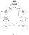
- FIG. 8is a diagram illustrating the different modes of operation in the FIG. 4 system and the conditions for switching between these different modes.
- the three modes of operationare an operating mode, a shutdown mode and a standby mode.
- the primary unitIn the operating mode, the primary unit is in the normal state (driven condition) most of the time, but periodically does a series of three ring-downs as described above. If the result of the ring-downs is that no secondary device requires power, the primary unit goes into a standby mode. If the result of the ring-downs is that a significant parasitic load 500 is present, the primary unit goes into a shutdown mode.
- the electrical drive unit 14In the standby mode, the electrical drive unit 14 is stopped for most of the time, thus consuming little power. Periodically the primary unit enters the normal state then does a series of ring-downs in respective probing periods, to check whether it should enter either the operating mode or the shutdown mode. Otherwise it remains in the standby mode.
- the shutdown modeis functionally identical to standby mode. However, the two modes may be distinguished by some user-interface feature such as an LED to prompt the user to remove any substantial parasitic load 500 .
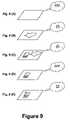
- FIGS. 9(A) to 9(E)illustrate the conditions under which the modes of FIG. 8 are selected in the FIG. 4 system.
- FIG. 9(A)there is no secondary device present in the vicinity of the primary unit. In this case, the primary unit is in the standby mode.
- FIG. 9(B)no secondary device is present but a substantial parasitic load is present in the vicinity of the primary unit. In this case, the primary unit is in the shutdown mode.
- FIG. 9(C)a secondary device and a substantial parasitic load are both present at the same time in the vicinity of the primary unit. In this case, the primary unit is in the shutdown mode.
- FIG. 9(A)there is no secondary device present in the vicinity of the primary unit. In this case, the primary unit is in the standby mode.
- FIG. 9(B)no secondary device is present but a substantial parasitic load is present in the vicinity of the primary unit. In this case, the primary unit is in the shutdown mode.
- FIG. 9(C)a secondary device and a substantial parasit
- a secondary deviceis present in the vicinity of the primary unit, but the load connected to the secondary device does not need any power at the current time. In this case, the primary unit is in the standby mode. Finally, in FIG. 9(E) a secondary device is present and its load needs power to charge or operate. Thus, the primary unit is in the operating mode.
Landscapes
- Engineering & Computer Science (AREA)
- Power Engineering (AREA)
- Computer Networks & Wireless Communication (AREA)
- Signal Processing (AREA)
- Charge And Discharge Circuits For Batteries Or The Like (AREA)
- General Induction Heating (AREA)
- Inverter Devices (AREA)
- Control Of Direct Current Motors (AREA)
- Electric Propulsion And Braking For Vehicles (AREA)
- Emergency Protection Circuit Devices (AREA)
Abstract
Description
- A primary unit having at least one primary coil, through which it drives an alternating current, creating a time-varying magnetic flux.
- A secondary device, separable from the primary unit, containing a secondary coil. When the secondary coil is placed in proximity to the time-varying flux created by the primary coil, the varying flux induces an alternating current in the secondary coil, and thus power may be transferred inductively from the primary unit to the secondary device.
- If the resistance of any metal is high, for example if it is impure or thin.
- If the material is ferromagnetic, for example steel. Such materials have high permeability, encouraging a high flux density within the material, causing large eddy currents and therefore large e2R losses.
- In EP0533247 and U.S. Pat. No. 6,118,249 the secondary device modulates its inductive load during charging, causing a corresponding variation in the power taken from the primary unit. This indicates to the primary unit that it should stay out of the standby state.
- In EP1022840 the primary unit varies the frequency of its drive, and thus the coupling factor to a tuned secondary unit. If the secondary unit is not taking power, there is no difference in the power taken as the frequency is swept and thus the primary unit goes into a standby state.
- In U.S. Pat. No. 5,536,979 the primary unit simply measures the power flowing in the primary coil, and enters a pulsing standby state if this is below a threshold.
- In U.S. Pat. No. 5,896,278 the primary unit contains detecting coils which have power coupled back into them according to the position of the secondary device. If the device is not present the primary unit enters a standby mode.
- In U.S. Pat. No. 5,952,814 the secondary device has a mechanical protrusion which fits a slot in the primary unit, activating it.
- In U.S. Pat. No. 6,028,413 the primary unit drives two coils, and there are a corresponding two power receiving secondary coils in the secondary unit. The primary unit measures the power delivered from each primary coil and enters standby mode if it is below a threshold.
- As mentioned above, in EP1022840 the primary unit varies the frequency of its drive. In this system, the secondary device is tuned, so this frequency variation will result in a variation of the power taken from the primary unit. If the load is instead a piece of metal, then varying the frequency will not have as much effect and the primary unit will enter a shutdown state.
- As mentioned above, in U.S. Pat. No. 5,952,814 a key in the secondary device activates the primary unit. The assumption is that if a secondary device is present then this will physically exclude any foreign objects.
- As mentioned above, in U.S. Pat. No. 6,028,413 the primary unit supplies power to the secondary device by driving two primary coils. If the amount of power supplied by the two coils is different, the primary unit assumes that the load is not a valid secondary device and enters shutdown mode.
- Energy coupled into the secondary coil of any secondary device present. This energy may be stored in a storage unit of the secondary device (if provided) and/or delivered to a load connected to the secondary device.
- Losses to any parasitic loads (foreign objects other than valid secondary devices) present.
- Other losses in the primary unit or any secondary devices/host objects present. These other losses include inefficiencies in the primary coil itself and any other components of the resonant tank (e.g. I2R losses in the copper of the coil or effective series resistance of any resonating capacitor). They also include any magnetic losses in the primary and secondary units, for example magnetic hysteretic loop losses in any cores associated with the primary unit and/or secondary device.
- Energy coupled into the secondary coil of any secondary device present. This energy may be stored in a storage unit of the secondary device and/or delivered to a load connected to the secondary device.
- Losses to any parasitic loads (foreign objects) present.
- Other losses in the primary unit or any secondary devices/host objects present. These other losses include inefficiencies in the primary coil itself and any other components of the resonant tank (e.g. I2R losses in the copper of the coil or effective series resistance of any resonating capacitor). They also include any magnetic losses in the primary and secondary units, for example magnetic hysteretic loop losses in any cores associated with the primary unit and/or secondary device.
- The drive electronics may be inactive and largely out of circuit during the ring-down, therefore their noise and tolerances do not affect the measurement accuracy.
- Since the method directly measures power taken, it is very hard to “trick”—it works reliably regardless of how power is being taken out, in contrast to other indirect techniques such as measuring inductance shift which make assumptions between the quality they measure and the parasitic load, which may not always be true.
where E is the energy, L the inductance, Î is the peak current, C is the capacitance and {circumflex over (V)} is the peak voltage.
Claims (37)
Priority Applications (6)
| Application Number | Priority Date | Filing Date | Title |
|---|---|---|---|
| US12/366,842US7868587B2 (en) | 2004-05-11 | 2009-02-06 | Controlling inductive power transfer systems |
| US12/885,445US8035340B2 (en) | 2004-05-11 | 2010-09-18 | Controlling inductive power transfer systems |
| US13/196,298US8610400B2 (en) | 2004-05-11 | 2011-08-02 | Controlling inductive power transfer systems |
| US14/082,979US9544022B2 (en) | 2004-05-11 | 2013-11-18 | Controlling inductive power transfer systems |
| US15/370,770US10158255B2 (en) | 2004-05-11 | 2016-12-06 | Controlling inductive power transfer systems |
| US16/221,922US10673281B2 (en) | 2004-05-11 | 2018-12-17 | Controlling inductive power transfer systems |
Applications Claiming Priority (3)
| Application Number | Priority Date | Filing Date | Title |
|---|---|---|---|
| GB0410503.7 | 2004-05-11 | ||
| GB0410503AGB2414120B (en) | 2004-05-11 | 2004-05-11 | Controlling inductive power transfer systems |
| PCT/GB2005/001833WO2005109598A1 (en) | 2004-05-11 | 2005-05-11 | Controlling inductive power transfer systems |
Related Parent Applications (1)
| Application Number | Title | Priority Date | Filing Date |
|---|---|---|---|
| PCT/GB2005/001833A-371-Of-InternationalWO2005109598A1 (en) | 2004-05-11 | 2005-05-11 | Controlling inductive power transfer systems |
Related Child Applications (1)
| Application Number | Title | Priority Date | Filing Date |
|---|---|---|---|
| US12/366,842DivisionUS7868587B2 (en) | 2004-05-11 | 2009-02-06 | Controlling inductive power transfer systems |
Publications (2)
| Publication Number | Publication Date |
|---|---|
| US20070216392A1 US20070216392A1 (en) | 2007-09-20 |
| US7554316B2true US7554316B2 (en) | 2009-06-30 |
Family
ID=32526836
Family Applications (7)
| Application Number | Title | Priority Date | Filing Date |
|---|---|---|---|
| US11/569,029Active2026-04-22US7554316B2 (en) | 2004-05-11 | 2005-05-11 | Controlling inductive power transfer systems |
| US12/366,842Expired - LifetimeUS7868587B2 (en) | 2004-05-11 | 2009-02-06 | Controlling inductive power transfer systems |
| US12/885,445Expired - LifetimeUS8035340B2 (en) | 2004-05-11 | 2010-09-18 | Controlling inductive power transfer systems |
| US13/196,298Active2025-12-16US8610400B2 (en) | 2004-05-11 | 2011-08-02 | Controlling inductive power transfer systems |
| US14/082,979Active2026-09-27US9544022B2 (en) | 2004-05-11 | 2013-11-18 | Controlling inductive power transfer systems |
| US15/370,770Active2025-10-21US10158255B2 (en) | 2004-05-11 | 2016-12-06 | Controlling inductive power transfer systems |
| US16/221,922Expired - LifetimeUS10673281B2 (en) | 2004-05-11 | 2018-12-17 | Controlling inductive power transfer systems |
Family Applications After (6)
| Application Number | Title | Priority Date | Filing Date |
|---|---|---|---|
| US12/366,842Expired - LifetimeUS7868587B2 (en) | 2004-05-11 | 2009-02-06 | Controlling inductive power transfer systems |
| US12/885,445Expired - LifetimeUS8035340B2 (en) | 2004-05-11 | 2010-09-18 | Controlling inductive power transfer systems |
| US13/196,298Active2025-12-16US8610400B2 (en) | 2004-05-11 | 2011-08-02 | Controlling inductive power transfer systems |
| US14/082,979Active2026-09-27US9544022B2 (en) | 2004-05-11 | 2013-11-18 | Controlling inductive power transfer systems |
| US15/370,770Active2025-10-21US10158255B2 (en) | 2004-05-11 | 2016-12-06 | Controlling inductive power transfer systems |
| US16/221,922Expired - LifetimeUS10673281B2 (en) | 2004-05-11 | 2018-12-17 | Controlling inductive power transfer systems |
Country Status (11)
| Country | Link |
|---|---|
| US (7) | US7554316B2 (en) |
| EP (3) | EP2375532B1 (en) |
| JP (2) | JP4741583B2 (en) |
| KR (2) | KR101237105B1 (en) |
| CN (4) | CN100479292C (en) |
| AT (1) | ATE450915T1 (en) |
| DE (1) | DE602005018045D1 (en) |
| ES (1) | ES2702986T3 (en) |
| GB (2) | GB2414120B (en) |
| PL (1) | PL2375532T3 (en) |
| WO (1) | WO2005109598A1 (en) |
Cited By (165)
| Publication number | Priority date | Publication date | Assignee | Title |
|---|---|---|---|---|
| US20070178945A1 (en)* | 2006-01-18 | 2007-08-02 | Cook Nigel P | Method and system for powering an electronic device via a wireless link |
| US20070182367A1 (en)* | 2006-01-31 | 2007-08-09 | Afshin Partovi | Inductive power source and charging system |
| US20080197713A1 (en)* | 2007-02-20 | 2008-08-21 | Seiko Epson Corporation | Power transmission control device, power transmission device, electronic instrument, and non-contact power transmission system |
| US20080197711A1 (en)* | 2007-02-20 | 2008-08-21 | Sony Ericsson Mobile Communications Japan, Inc. | Electronic device |
| US20090045772A1 (en)* | 2007-06-11 | 2009-02-19 | Nigelpower, Llc | Wireless Power System and Proximity Effects |
| US20090212628A1 (en)* | 1999-06-21 | 2009-08-27 | Access Business Group International Llc | System and method for inductive power supply control using remote device power requirements |
| US20090273242A1 (en)* | 2008-05-05 | 2009-11-05 | Nigelpower, Llc | Wireless Delivery of power to a Fixed-Geometry power part |
| US20090284245A1 (en)* | 2008-05-13 | 2009-11-19 | Qualcomm Incorporated | Wireless power transfer for appliances and equipments |
| US20090322280A1 (en)* | 2008-06-25 | 2009-12-31 | Seiko Epson Corporation | Power transmission control device, power transmission device, power receiving control device, power receiving device, and electronic apparatus |
| US20100014207A1 (en)* | 2007-03-06 | 2010-01-21 | Giesecke & Devrlent Gmbh | Device for actuating an actuator |
| US20100186618A1 (en)* | 2009-01-23 | 2010-07-29 | Magnemotion, Inc. | Transport system powered by short block linear synchronous motors |
| US20100201533A1 (en)* | 2009-02-10 | 2010-08-12 | Qualcomm Incorporated | Conveying device information relating to wireless charging |
| US20100201189A1 (en)* | 2008-05-13 | 2010-08-12 | Qualcomm Incorporated | Wireless power transfer for vehicles |
| US20100244584A1 (en)* | 2007-10-09 | 2010-09-30 | Powermat Ltd. | Inductive power providing system having moving outlets |
| US20100259110A1 (en)* | 2008-09-27 | 2010-10-14 | Kurs Andre B | Resonator optimizations for wireless energy transfer |
| US20110043048A1 (en)* | 2008-09-27 | 2011-02-24 | Aristeidis Karalis | Wireless energy transfer using object positioning for low loss |
| US20110095618A1 (en)* | 2008-09-27 | 2011-04-28 | Schatz David A | Wireless energy transfer using repeater resonators |
| US20110101783A1 (en)* | 2008-07-28 | 2011-05-05 | Eveready Battery Company, Inc. | Electrical Power Distribution System and Method Thereof |
| US20110109262A1 (en)* | 2009-11-06 | 2011-05-12 | Toyota Motor Engineering & Manufacturing North America, Inc. | Wireless energy transfer antennas and energy charging systems |
| US7948208B2 (en) | 2006-06-01 | 2011-05-24 | Mojo Mobility, Inc. | Power source, charging system, and inductive receiver for mobile devices |
| US20110173865A1 (en)* | 2010-01-15 | 2011-07-21 | Colt Canada Corporation | Rail for inductively powering firearm accessories |
| US8061864B2 (en) | 2009-05-12 | 2011-11-22 | Kimball International, Inc. | Furniture with wireless power |
| US8169185B2 (en) | 2006-01-31 | 2012-05-01 | Mojo Mobility, Inc. | System and method for inductive charging of portable devices |
| US20120146576A1 (en)* | 2010-06-11 | 2012-06-14 | Mojo Mobility, Inc. | System for wireless power transfer that supports interoperability, and multi-pole magnets for use therewith |
| US20120153739A1 (en)* | 2010-12-21 | 2012-06-21 | Cooper Emily B | Range adaptation mechanism for wireless power transfer |
| US8373514B2 (en) | 2007-10-11 | 2013-02-12 | Qualcomm Incorporated | Wireless power transfer using magneto mechanical systems |
| US8378523B2 (en)* | 2007-03-02 | 2013-02-19 | Qualcomm Incorporated | Transmitters and receivers for wireless energy transfer |
| US8378522B2 (en) | 2007-03-02 | 2013-02-19 | Qualcomm, Incorporated | Maximizing power yield from wireless power magnetic resonators |
| US8482157B2 (en) | 2007-03-02 | 2013-07-09 | Qualcomm Incorporated | Increasing the Q factor of a resonator |
| US8614561B2 (en) | 2008-03-07 | 2013-12-24 | Canon Kabushiki Kaisha | Charging apparatus |
| US8618696B2 (en) | 2008-09-27 | 2013-12-31 | Witricity Corporation | Wireless energy transfer systems |
| US8629578B2 (en) | 2008-09-27 | 2014-01-14 | Witricity Corporation | Wireless energy transfer systems |
| US8629576B2 (en) | 2008-03-28 | 2014-01-14 | Qualcomm Incorporated | Tuning and gain control in electro-magnetic power systems |
| US8643326B2 (en) | 2008-09-27 | 2014-02-04 | Witricity Corporation | Tunable wireless energy transfer systems |
| WO2014026278A1 (en)* | 2012-08-16 | 2014-02-20 | Colt Canada Corporation | Apparatus and method for powering and networking a rail of a firearm |
| US8667452B2 (en) | 2011-11-04 | 2014-03-04 | Witricity Corporation | Wireless energy transfer modeling tool |
| US8669676B2 (en) | 2008-09-27 | 2014-03-11 | Witricity Corporation | Wireless energy transfer across variable distances using field shaping with magnetic materials to improve the coupling factor |
| US20140084857A1 (en)* | 2012-09-27 | 2014-03-27 | ConvenientPower HK Ltd. | Methods And Systems For Detecting Foreign Objects In A Wireless Charging System |
| US8692412B2 (en) | 2008-09-27 | 2014-04-08 | Witricity Corporation | Temperature compensation in a wireless transfer system |
| US8716903B2 (en) | 2008-09-27 | 2014-05-06 | Witricity Corporation | Low AC resistance conductor designs |
| US8723366B2 (en) | 2008-09-27 | 2014-05-13 | Witricity Corporation | Wireless energy transfer resonator enclosures |
| US8725330B2 (en) | 2010-06-02 | 2014-05-13 | Bryan Marc Failing | Increasing vehicle security |
| US8772973B2 (en) | 2008-09-27 | 2014-07-08 | Witricity Corporation | Integrated resonator-shield structures |
| US8805530B2 (en) | 2007-06-01 | 2014-08-12 | Witricity Corporation | Power generation for implantable devices |
| US8847548B2 (en) | 2008-09-27 | 2014-09-30 | Witricity Corporation | Wireless energy transfer for implantable devices |
| US8863669B2 (en) | 2011-06-07 | 2014-10-21 | Magnemotion, Inc. | Versatile control of a linear synchronous motor propulsion system |
| US20140312688A1 (en)* | 2007-03-22 | 2014-10-23 | Powermat Technologies, Ltd. | Efficiency monitor for inductive power transmission |
| US8901779B2 (en) | 2008-09-27 | 2014-12-02 | Witricity Corporation | Wireless energy transfer with resonator arrays for medical applications |
| US8901778B2 (en) | 2008-09-27 | 2014-12-02 | Witricity Corporation | Wireless energy transfer with variable size resonators for implanted medical devices |
| US8907531B2 (en) | 2008-09-27 | 2014-12-09 | Witricity Corporation | Wireless energy transfer with variable size resonators for medical applications |
| US8912687B2 (en) | 2008-09-27 | 2014-12-16 | Witricity Corporation | Secure wireless energy transfer for vehicle applications |
| US8922066B2 (en) | 2008-09-27 | 2014-12-30 | Witricity Corporation | Wireless energy transfer with multi resonator arrays for vehicle applications |
| US8928276B2 (en) | 2008-09-27 | 2015-01-06 | Witricity Corporation | Integrated repeaters for cell phone applications |
| US8933594B2 (en) | 2008-09-27 | 2015-01-13 | Witricity Corporation | Wireless energy transfer for vehicles |
| US8937408B2 (en) | 2008-09-27 | 2015-01-20 | Witricity Corporation | Wireless energy transfer for medical applications |
| US20150020427A1 (en) | 2010-01-15 | 2015-01-22 | David Walter Compton | Apparatus and method for powering and networking a rail of a firearm |
| US8946938B2 (en) | 2008-09-27 | 2015-02-03 | Witricity Corporation | Safety systems for wireless energy transfer in vehicle applications |
| US8947186B2 (en) | 2008-09-27 | 2015-02-03 | Witricity Corporation | Wireless energy transfer resonator thermal management |
| US8957549B2 (en) | 2008-09-27 | 2015-02-17 | Witricity Corporation | Tunable wireless energy transfer for in-vehicle applications |
| US8963488B2 (en) | 2008-09-27 | 2015-02-24 | Witricity Corporation | Position insensitive wireless charging |
| US8967051B2 (en) | 2009-01-23 | 2015-03-03 | Magnemotion, Inc. | Transport system powered by short block linear synchronous motors and switching mechanism |
| US20150091523A1 (en)* | 2013-10-02 | 2015-04-02 | Mediatek Singapore Pte. Ltd. | Wireless charger system that has variable power / adaptive load modulation |
| US9035499B2 (en) | 2008-09-27 | 2015-05-19 | Witricity Corporation | Wireless energy transfer for photovoltaic panels |
| US9032880B2 (en) | 2009-01-23 | 2015-05-19 | Magnemotion, Inc. | Transport system powered by short block linear synchronous motors and switching mechanism |
| US9065423B2 (en) | 2008-09-27 | 2015-06-23 | Witricity Corporation | Wireless energy distribution system |
| US9093853B2 (en) | 2008-09-27 | 2015-07-28 | Witricity Corporation | Flexible resonator attachment |
| US9106083B2 (en) | 2011-01-18 | 2015-08-11 | Mojo Mobility, Inc. | Systems and method for positioning freedom, and support of different voltages, protocols, and power levels in a wireless power system |
| US9105959B2 (en) | 2008-09-27 | 2015-08-11 | Witricity Corporation | Resonator enclosure |
| US9106203B2 (en) | 2008-09-27 | 2015-08-11 | Witricity Corporation | Secure wireless energy transfer in medical applications |
| US9124308B2 (en) | 2009-05-12 | 2015-09-01 | Kimball International, Inc. | Furniture with wireless power |
| US9130602B2 (en) | 2006-01-18 | 2015-09-08 | Qualcomm Incorporated | Method and apparatus for delivering energy to an electrical or electronic device via a wireless link |
| US9160203B2 (en) | 2008-09-27 | 2015-10-13 | Witricity Corporation | Wireless powered television |
| US9184595B2 (en) | 2008-09-27 | 2015-11-10 | Witricity Corporation | Wireless energy transfer in lossy environments |
| US9246336B2 (en) | 2008-09-27 | 2016-01-26 | Witricity Corporation | Resonator optimizations for wireless energy transfer |
| US9287607B2 (en) | 2012-07-31 | 2016-03-15 | Witricity Corporation | Resonator fine tuning |
| US9306635B2 (en) | 2012-01-26 | 2016-04-05 | Witricity Corporation | Wireless energy transfer with reduced fields |
| US9312924B2 (en) | 2009-02-10 | 2016-04-12 | Qualcomm Incorporated | Systems and methods relating to multi-dimensional wireless charging |
| US9318257B2 (en) | 2011-10-18 | 2016-04-19 | Witricity Corporation | Wireless energy transfer for packaging |
| US9318922B2 (en) | 2008-09-27 | 2016-04-19 | Witricity Corporation | Mechanically removable wireless power vehicle seat assembly |
| US9343922B2 (en) | 2012-06-27 | 2016-05-17 | Witricity Corporation | Wireless energy transfer for rechargeable batteries |
| US9356659B2 (en) | 2011-01-18 | 2016-05-31 | Mojo Mobility, Inc. | Chargers and methods for wireless power transfer |
| US9369182B2 (en) | 2008-09-27 | 2016-06-14 | Witricity Corporation | Wireless energy transfer using variable size resonators and system monitoring |
| US9384885B2 (en) | 2011-08-04 | 2016-07-05 | Witricity Corporation | Tunable wireless power architectures |
| US9396867B2 (en) | 2008-09-27 | 2016-07-19 | Witricity Corporation | Integrated resonator-shield structures |
| US9404954B2 (en) | 2012-10-19 | 2016-08-02 | Witricity Corporation | Foreign object detection in wireless energy transfer systems |
| US9421388B2 (en) | 2007-06-01 | 2016-08-23 | Witricity Corporation | Power generation for implantable devices |
| US9442172B2 (en) | 2011-09-09 | 2016-09-13 | Witricity Corporation | Foreign object detection in wireless energy transfer systems |
| US9444520B2 (en) | 2008-09-27 | 2016-09-13 | Witricity Corporation | Wireless energy transfer converters |
| US9449757B2 (en) | 2012-11-16 | 2016-09-20 | Witricity Corporation | Systems and methods for wireless power system with improved performance and/or ease of use |
| US9496732B2 (en) | 2011-01-18 | 2016-11-15 | Mojo Mobility, Inc. | Systems and methods for wireless power transfer |
| US9515494B2 (en) | 2008-09-27 | 2016-12-06 | Witricity Corporation | Wireless power system including impedance matching network |
| US20160372934A1 (en)* | 2015-06-18 | 2016-12-22 | STMicroelectronics (Grand Ouest) SAS | Method for managing contactless power transfer from a transmitter to a receiver, and corresponding transmitter |
| US9544683B2 (en) | 2008-09-27 | 2017-01-10 | Witricity Corporation | Wirelessly powered audio devices |
| US9583953B2 (en) | 2009-02-10 | 2017-02-28 | Qualcomm Incorporated | Wireless power transfer for portable enclosures |
| US9595378B2 (en) | 2012-09-19 | 2017-03-14 | Witricity Corporation | Resonator enclosure |
| US9602168B2 (en) | 2010-08-31 | 2017-03-21 | Witricity Corporation | Communication in wireless energy transfer systems |
| US9601266B2 (en) | 2008-09-27 | 2017-03-21 | Witricity Corporation | Multiple connected resonators with a single electronic circuit |
| US9601267B2 (en) | 2013-07-03 | 2017-03-21 | Qualcomm Incorporated | Wireless power transmitter with a plurality of magnetic oscillators |
| US9601270B2 (en) | 2008-09-27 | 2017-03-21 | Witricity Corporation | Low AC resistance conductor designs |
| US9623763B2 (en) | 2011-05-26 | 2017-04-18 | Conductix—Wampfler Gmbh | Method for detecting an electrically conductive foreign body in a region of a device for inductively transmitting electrical energy and device for inductively transmitting electrical energy |
| US9642219B2 (en) | 2014-06-05 | 2017-05-02 | Steelcase Inc. | Environment optimization for space based on presence and activities |
| US9694702B2 (en) | 2012-09-11 | 2017-07-04 | Bombardier Transportation Gmbh | Circuit arrangement and method of operating a circuit arrangement |
| US9722447B2 (en) | 2012-03-21 | 2017-08-01 | Mojo Mobility, Inc. | System and method for charging or powering devices, such as robots, electric vehicles, or other mobile devices or equipment |
| US9744858B2 (en) | 2008-09-27 | 2017-08-29 | Witricity Corporation | System for wireless energy distribution in a vehicle |
| US9754718B2 (en) | 2008-09-27 | 2017-09-05 | Witricity Corporation | Resonator arrays for wireless energy transfer |
| US9774086B2 (en) | 2007-03-02 | 2017-09-26 | Qualcomm Incorporated | Wireless power apparatus and methods |
| US9780573B2 (en) | 2014-02-03 | 2017-10-03 | Witricity Corporation | Wirelessly charged battery system |
| US9802507B2 (en) | 2013-09-21 | 2017-10-31 | Magnemotion, Inc. | Linear motor transport for packaging and other uses |
| US9837860B2 (en) | 2014-05-05 | 2017-12-05 | Witricity Corporation | Wireless power transmission systems for elevators |
| US9837846B2 (en) | 2013-04-12 | 2017-12-05 | Mojo Mobility, Inc. | System and method for powering or charging receivers or devices having small surface areas or volumes |
| US9842687B2 (en) | 2014-04-17 | 2017-12-12 | Witricity Corporation | Wireless power transfer systems with shaped magnetic components |
| US9843217B2 (en) | 2015-01-05 | 2017-12-12 | Witricity Corporation | Wireless energy transfer for wearables |
| US9842688B2 (en) | 2014-07-08 | 2017-12-12 | Witricity Corporation | Resonator balancing in wireless power transfer systems |
| US9852388B1 (en) | 2014-10-03 | 2017-12-26 | Steelcase, Inc. | Method and system for locating resources and communicating within an enterprise |
| US9857821B2 (en) | 2013-08-14 | 2018-01-02 | Witricity Corporation | Wireless power transfer frequency adjustment |
| US9891023B2 (en) | 2010-01-15 | 2018-02-13 | Colt Canada Ip Holding Partnership | Apparatus and method for inductively powering and networking a rail of a firearm |
| US9892849B2 (en) | 2014-04-17 | 2018-02-13 | Witricity Corporation | Wireless power transfer systems with shield openings |
| US20180069422A1 (en)* | 2005-03-03 | 2018-03-08 | Sony Corporation | System, apparatus and method for supplying electric power, apparatus and method for receiving electric power, storage medium and program |
| US9921726B1 (en) | 2016-06-03 | 2018-03-20 | Steelcase Inc. | Smart workstation method and system |
| US9929721B2 (en) | 2015-10-14 | 2018-03-27 | Witricity Corporation | Phase and amplitude detection in wireless energy transfer systems |
| US9948145B2 (en) | 2011-07-08 | 2018-04-17 | Witricity Corporation | Wireless power transfer for a seat-vest-helmet system |
| US9954375B2 (en) | 2014-06-20 | 2018-04-24 | Witricity Corporation | Wireless power transfer systems for surfaces |
| US9955318B1 (en) | 2014-06-05 | 2018-04-24 | Steelcase Inc. | Space guidance and management system and method |
| US9952266B2 (en) | 2014-02-14 | 2018-04-24 | Witricity Corporation | Object detection for wireless energy transfer systems |
| US20180191200A1 (en)* | 2007-12-21 | 2018-07-05 | Philips Ip Ventures B.V. | Inductive power transfer |
| US10018744B2 (en) | 2014-05-07 | 2018-07-10 | Witricity Corporation | Foreign object detection in wireless energy transfer systems |
| US10063104B2 (en) | 2016-02-08 | 2018-08-28 | Witricity Corporation | PWM capacitor control |
| US10063110B2 (en) | 2015-10-19 | 2018-08-28 | Witricity Corporation | Foreign object detection in wireless energy transfer systems |
| US10075019B2 (en) | 2015-11-20 | 2018-09-11 | Witricity Corporation | Voltage source isolation in wireless power transfer systems |
| US10115520B2 (en) | 2011-01-18 | 2018-10-30 | Mojo Mobility, Inc. | Systems and method for wireless power transfer |
| US10141788B2 (en) | 2015-10-22 | 2018-11-27 | Witricity Corporation | Dynamic tuning in wireless energy transfer systems |
| US10161752B1 (en) | 2014-10-03 | 2018-12-25 | Steelcase Inc. | Method and system for locating resources and communicating within an enterprise |
| US10248899B2 (en) | 2015-10-06 | 2019-04-02 | Witricity Corporation | RFID tag and transponder detection in wireless energy transfer systems |
| US10263473B2 (en) | 2016-02-02 | 2019-04-16 | Witricity Corporation | Controlling wireless power transfer systems |
| US10264213B1 (en) | 2016-12-15 | 2019-04-16 | Steelcase Inc. | Content amplification system and method |
| US10337834B2 (en) | 2010-01-15 | 2019-07-02 | Colt Canada Ip Holding Partnership | Networked battle system or firearm |
| US10353664B2 (en) | 2014-03-07 | 2019-07-16 | Steelcase Inc. | Method and system for facilitating collaboration sessions |
| US10424976B2 (en) | 2011-09-12 | 2019-09-24 | Witricity Corporation | Reconfigurable control architectures and algorithms for electric vehicle wireless energy transfer systems |
| US10433646B1 (en) | 2014-06-06 | 2019-10-08 | Steelcaase Inc. | Microclimate control systems and methods |
| US10470010B2 (en) | 2010-01-15 | 2019-11-05 | Colt Canada Ip Holding Partnership | Networked battle system or firearm |
| US10477619B2 (en) | 2010-01-15 | 2019-11-12 | Colt Canada Ip Holding Partnership | Networked battle system or firearm |
| US10477618B2 (en) | 2010-01-15 | 2019-11-12 | Colt Canada Ip Holding Partnership | Networked battle system or firearm |
| US10574091B2 (en) | 2014-07-08 | 2020-02-25 | Witricity Corporation | Enclosures for high power wireless power transfer systems |
| US20200099256A1 (en)* | 2016-12-16 | 2020-03-26 | General Electric Company | Calibration device and method for determining an optimal operating frequency of a power transfer system |
| US10614694B1 (en) | 2014-06-06 | 2020-04-07 | Steelcase Inc. | Powered furniture assembly |
| US10720797B2 (en)* | 2017-05-26 | 2020-07-21 | California Institute Of Technology | Method and apparatus for dynamic RF lens focusing and tracking of wireless power recovery unit |
| US10733371B1 (en) | 2015-06-02 | 2020-08-04 | Steelcase Inc. | Template based content preparation system for use with a plurality of space types |
| US11004597B2 (en)* | 2013-05-16 | 2021-05-11 | Sony Corporation | Detection apparatus, power supply system, and method of controlling detection apparatus |
| US11031818B2 (en) | 2017-06-29 | 2021-06-08 | Witricity Corporation | Protection and control of wireless power systems |
| US11095164B2 (en) | 2014-08-19 | 2021-08-17 | California Institute Of Technology | Wireless power transfer |
| US11114895B2 (en) | 2007-01-29 | 2021-09-07 | Powermat Technologies, Ltd. | Pinless power coupling |
| EP3879671A1 (en) | 2020-03-10 | 2021-09-15 | Koninklijke Philips N.V. | Wireless power transfer |
| US11146113B2 (en) | 2013-11-22 | 2021-10-12 | California Institute Of Technology | Generator unit for wireless power transfer |
| US11201500B2 (en) | 2006-01-31 | 2021-12-14 | Mojo Mobility, Inc. | Efficiencies and flexibilities in inductive (wireless) charging |
| US11211975B2 (en) | 2008-05-07 | 2021-12-28 | Mojo Mobility, Inc. | Contextually aware charging of mobile devices |
| US11321643B1 (en) | 2014-03-07 | 2022-05-03 | Steelcase Inc. | Method and system for facilitating collaboration sessions |
| US11329511B2 (en) | 2006-06-01 | 2022-05-10 | Mojo Mobility Inc. | Power source, charging system, and inductive receiver for mobile devices |
| US11398747B2 (en) | 2011-01-18 | 2022-07-26 | Mojo Mobility, Inc. | Inductive powering and/or charging with more than one power level and/or frequency |
| US11444485B2 (en) | 2019-02-05 | 2022-09-13 | Mojo Mobility, Inc. | Inductive charging system with charging electronics physically separated from charging coil |
| US11502552B2 (en) | 2012-11-09 | 2022-11-15 | California Institute Of Technology | Smart RF lensing: efficient, dynamic and mobile wireless power transfer |
| US11616520B2 (en) | 2012-11-09 | 2023-03-28 | California Institute Of Technology | RF receiver |
| US11744376B2 (en) | 2014-06-06 | 2023-09-05 | Steelcase Inc. | Microclimate control systems and methods |
| US11843260B2 (en) | 2012-11-09 | 2023-12-12 | California Institute Of Technology | Generator unit for wireless power transfer |
| US11984739B1 (en) | 2020-07-31 | 2024-05-14 | Steelcase Inc. | Remote power systems, apparatus and methods |
| US12118178B1 (en) | 2020-04-08 | 2024-10-15 | Steelcase Inc. | Wayfinding services method and apparatus |
Families Citing this family (212)
| Publication number | Priority date | Publication date | Assignee | Title |
|---|---|---|---|---|
| GB2414120B (en) | 2004-05-11 | 2008-04-02 | Splashpower Ltd | Controlling inductive power transfer systems |
| NZ540927A (en)* | 2005-06-22 | 2008-03-28 | Traffic Electronics Ltd | Communication system for inductive power transfer system |
| US7825543B2 (en) | 2005-07-12 | 2010-11-02 | Massachusetts Institute Of Technology | Wireless energy transfer |
| CN101860089B (en) | 2005-07-12 | 2013-02-06 | 麻省理工学院 | wireless non-radiative energy transfer |
| US7514899B2 (en) | 2005-11-18 | 2009-04-07 | Avago Technologies Ecbu Ip (Singapore) Pte. Ltd. | Method and apparatus for optical wireless charging |
| US7989986B2 (en)* | 2006-03-23 | 2011-08-02 | Access Business Group International Llc | Inductive power supply with device identification |
| US8004235B2 (en) | 2006-09-29 | 2011-08-23 | Access Business Group International Llc | System and method for inductively charging a battery |
| US8099140B2 (en)* | 2006-11-24 | 2012-01-17 | Semiconductor Energy Laboratory Co., Ltd. | Wireless power supply system and wireless power supply method |
| US8195340B1 (en)* | 2006-12-18 | 2012-06-05 | Sprint Communications Company L.P. | Data center emergency power management |
| JP4600470B2 (en)* | 2007-02-20 | 2010-12-15 | セイコーエプソン株式会社 | Power transmission control device, power transmission device, electronic device, and non-contact power transmission system |
| KR102128564B1 (en)* | 2007-05-10 | 2020-07-01 | 오클랜드 유니서비시즈 리미티드 | Multi power sourced electric vehicle |
| JP4743173B2 (en)* | 2007-06-29 | 2011-08-10 | セイコーエプソン株式会社 | Power transmission control device, power transmission device, non-contact power transmission system, and electronic device |
| JP2009027781A (en) | 2007-07-17 | 2009-02-05 | Seiko Epson Corp | Power reception controller, power receiver, contactless power transmitting system, charge controller, battery device, and electronic equipment |
| KR101502248B1 (en) | 2007-09-19 | 2015-03-12 | 퀄컴 인코포레이티드 | Maximizing power yield from wireless power magnetic resonators |
| US8729734B2 (en) | 2007-11-16 | 2014-05-20 | Qualcomm Incorporated | Wireless power bridge |
| WO2010036279A1 (en)* | 2007-11-28 | 2010-04-01 | Qualcomm Incorporated | Wireless power range increase using parasitic antennas |
| WO2009069844A1 (en)* | 2007-11-30 | 2009-06-04 | Chun-Kil Jung | Multiple non-contact charging system of wireless power transmision and control method thereof |
| JP5544705B2 (en)* | 2008-01-09 | 2014-07-09 | セイコーエプソン株式会社 | Power transmission control device, power transmission device, non-contact power transmission system, electronic device, and power transmission control method |
| JP5556002B2 (en)* | 2008-01-09 | 2014-07-23 | セイコーエプソン株式会社 | Power transmission control device, power transmission device, non-contact power transmission system, and electronic device |
| EP2083407B1 (en)* | 2008-01-25 | 2012-05-16 | Pepperl + Fuchs GmbH | Device and method for contact-free energy and data transfer |
| KR100976161B1 (en) | 2008-02-20 | 2010-08-16 | 정춘길 | Contactless charging system and its charging control method |
| JP2011514129A (en) | 2008-02-22 | 2011-04-28 | アクセス ビジネス グループ インターナショナル リミテッド ライアビリティ カンパニー | Induction power supply system with battery type detection function |
| CN102084442B (en)* | 2008-03-17 | 2013-12-04 | 鲍尔马特技术有限公司 | Inductive transmission system |
| US9337902B2 (en)* | 2008-03-17 | 2016-05-10 | Powermat Technologies Ltd. | System and method for providing wireless power transfer functionality to an electrical device |
| US9024581B2 (en) | 2008-05-21 | 2015-05-05 | James W. McGinley | Charger plug with improved package |
| US11979201B2 (en) | 2008-07-02 | 2024-05-07 | Powermat Technologies Ltd. | System and method for coded communication signals regulating inductive power transmissions |
| US8981598B2 (en)* | 2008-07-02 | 2015-03-17 | Powermat Technologies Ltd. | Energy efficient inductive power transmission system and method |
| US8278784B2 (en)* | 2008-07-28 | 2012-10-02 | Qualcomm Incorporated | Wireless power transmission for electronic devices |
| JP5241381B2 (en)* | 2008-08-25 | 2013-07-17 | 株式会社日立製作所 | Power receiver |
| JP4911148B2 (en)* | 2008-09-02 | 2012-04-04 | ソニー株式会社 | Contactless power supply |
| US8471410B2 (en) | 2008-09-27 | 2013-06-25 | Witricity Corporation | Wireless energy transfer over distance using field shaping to improve the coupling factor |
| US8476788B2 (en) | 2008-09-27 | 2013-07-02 | Witricity Corporation | Wireless energy transfer with high-Q resonators using field shaping to improve K |
| US8304935B2 (en) | 2008-09-27 | 2012-11-06 | Witricity Corporation | Wireless energy transfer using field shaping to reduce loss |
| US8587153B2 (en) | 2008-09-27 | 2013-11-19 | Witricity Corporation | Wireless energy transfer using high Q resonators for lighting applications |
| US8461722B2 (en) | 2008-09-27 | 2013-06-11 | Witricity Corporation | Wireless energy transfer using conducting surfaces to shape field and improve K |
| US8466583B2 (en) | 2008-09-27 | 2013-06-18 | Witricity Corporation | Tunable wireless energy transfer for outdoor lighting applications |
| US8324759B2 (en) | 2008-09-27 | 2012-12-04 | Witricity Corporation | Wireless energy transfer using magnetic materials to shape field and reduce loss |
| US8441154B2 (en) | 2008-09-27 | 2013-05-14 | Witricity Corporation | Multi-resonator wireless energy transfer for exterior lighting |
| US8587155B2 (en) | 2008-09-27 | 2013-11-19 | Witricity Corporation | Wireless energy transfer using repeater resonators |
| US8552592B2 (en) | 2008-09-27 | 2013-10-08 | Witricity Corporation | Wireless energy transfer with feedback control for lighting applications |
| US8487480B1 (en) | 2008-09-27 | 2013-07-16 | Witricity Corporation | Wireless energy transfer resonator kit |
| EP3179640A1 (en) | 2008-09-27 | 2017-06-14 | WiTricity Corporation | Wireless energy transfer systems |
| US8461720B2 (en) | 2008-09-27 | 2013-06-11 | Witricity Corporation | Wireless energy transfer using conducting surfaces to shape fields and reduce loss |
| US8686598B2 (en) | 2008-09-27 | 2014-04-01 | Witricity Corporation | Wireless energy transfer for supplying power and heat to a device |
| US8692410B2 (en) | 2008-09-27 | 2014-04-08 | Witricity Corporation | Wireless energy transfer with frequency hopping |
| US8362651B2 (en) | 2008-10-01 | 2013-01-29 | Massachusetts Institute Of Technology | Efficient near-field wireless energy transfer using adiabatic system variations |
| WO2010037166A1 (en)* | 2008-10-03 | 2010-04-08 | Bluechiip Pty Ltd | Ringup/ ringdown interrogation of rfid tags |
| JP5258521B2 (en) | 2008-11-14 | 2013-08-07 | トヨタ自動車株式会社 | Power supply system |
| US9178376B2 (en) | 2008-12-12 | 2015-11-03 | Hanrim Postech Co., Ltd. | Non-contact charging station with power transmission planar spiral core, non-contact power-receiving apparatus, and method for controlling the same |
| CN101919139B (en) | 2008-12-12 | 2014-08-20 | 翰林Postech株式会社 | Non-contact power transmission equipment |
| US20100201310A1 (en)* | 2009-02-06 | 2010-08-12 | Broadcom Corporation | Wireless power transfer system |
| US8427100B2 (en)* | 2009-02-06 | 2013-04-23 | Broadcom Corporation | Increasing efficiency of wireless power transfer |
| US8427330B2 (en)* | 2009-02-06 | 2013-04-23 | Broadcom Corporation | Efficiency indicator for increasing efficiency of wireless power transfer |
| JP2010183814A (en)* | 2009-02-09 | 2010-08-19 | Toyota Industries Corp | Non-contact power transmitter |
| US9240824B2 (en) | 2009-02-13 | 2016-01-19 | Qualcomm Incorporated | Wireless power and wireless communication for electronic devices |
| JP4849142B2 (en)* | 2009-02-27 | 2012-01-11 | ソニー株式会社 | Power supply device and power transmission system |
| EP2406865A2 (en)* | 2009-03-12 | 2012-01-18 | Powermat Ltd | System and method for controlling inductive power to multiple modules |
| RU2548367C2 (en)* | 2009-07-13 | 2015-04-20 | Конинклейке Филипс Электроникс Н.В. | Energy inductive transmission |
| EP2454119A2 (en)* | 2009-07-15 | 2012-05-23 | Conductix-Wampfler AG | System for inductively charging vehicles, comprising an electronic positioning aid |
| US9312728B2 (en)* | 2009-08-24 | 2016-04-12 | Access Business Group International Llc | Physical and virtual identification in a wireless power network |
| FI20095973A0 (en) | 2009-09-22 | 2009-09-22 | Powerkiss Oy | Inductive power supply |
| US20110164471A1 (en)* | 2010-01-05 | 2011-07-07 | Access Business Group International Llc | Integrated wireless power system |
| GB2490074B (en)* | 2010-02-08 | 2014-02-19 | Access Business Group Int Llc | Input parasitic metal detection |
| US9106086B2 (en)* | 2010-03-11 | 2015-08-11 | Qualcomm Incorporated | Detection and protection of devices within a wireless power system |
| US9413197B2 (en) | 2010-05-31 | 2016-08-09 | Fu Da Tong Technology Co., Ltd. | Inductive power supply system and intruding metal detection method thereof |
| TWI473381B (en)* | 2011-09-20 | 2015-02-11 | Fu Da Tong Technology Co Ltd | Induction power supply system and intruding metal detection method thereof |
| JP2012016125A (en)* | 2010-06-30 | 2012-01-19 | Panasonic Electric Works Co Ltd | Non-contact power supply system and metal foreign matter detection device for non-contact power supply system |
| CN102959823B (en)* | 2010-07-02 | 2015-08-19 | 皇家飞利浦电子股份有限公司 | Induction type electric power supply system |
| EP2591535A2 (en)* | 2010-07-07 | 2013-05-15 | Robert Bosch GmbH | Foreign object detection in inductive coupled wireless power transfer environment using thermal sensors |
| US9853478B2 (en) | 2010-07-28 | 2017-12-26 | Qualcomm Incorporated | Low power detection of wireless power devices |
| EP2415961A1 (en)* | 2010-08-03 | 2012-02-08 | Vetco Gray Controls Limited | Supplying power to underwater devices |
| JP2012055086A (en)* | 2010-09-01 | 2012-03-15 | Hitachi Maxell Energy Ltd | Charging unit and electric apparatus including the same |
| US9294153B2 (en)* | 2010-09-23 | 2016-03-22 | Texas Instruments Incorporated | Systems and methods of wireless power transfer with interference detection |
| US9219378B2 (en) | 2010-11-01 | 2015-12-22 | Qualcomm Incorporated | Wireless charging of devices |
| CN103229194B (en)* | 2010-11-29 | 2016-08-17 | 富士通株式会社 | Portable set and feed system |
| JP5152446B2 (en)* | 2010-12-01 | 2013-02-27 | トヨタ自動車株式会社 | Non-contact power supply equipment |
| US8983374B2 (en) | 2010-12-13 | 2015-03-17 | Qualcomm Incorporated | Receiver for near field communication and wireless power functionalities |
| CN102570623A (en)* | 2010-12-27 | 2012-07-11 | 佛山市顺德区顺达电脑厂有限公司 | Wireless power supply control device and method |
| EP2689512B1 (en) | 2011-03-21 | 2016-11-30 | Koninklijke Philips N.V. | Calculating power loss for inductive power transmission |
| KR101397624B1 (en)* | 2011-03-23 | 2014-05-22 | 주식회사 한림포스텍 | Method for controlling power transmission in wireless power transmission apparatus and wireless power transmission apparatus thereof |
| US20120244969A1 (en) | 2011-03-25 | 2012-09-27 | May Patents Ltd. | System and Method for a Motion Sensing Device |
| KR101765128B1 (en) | 2011-05-12 | 2017-08-14 | 삼성전자주식회사 | Method and apparatus for avoiding noise in no contact charging system |
| US9000620B2 (en) | 2011-05-31 | 2015-04-07 | Samsung Electronics Co., Ltd. | Apparatus and method of dividing wireless power in wireless resonant power transmission system |
| KR101950309B1 (en) | 2011-06-07 | 2019-02-21 | 삼성전자주식회사 | Method for controlling wireless power of receiver in wireless power transmitting/receiving system and the receiver |
| JP5703988B2 (en)* | 2011-06-17 | 2015-04-22 | トヨタ自動車株式会社 | Power receiving device, power transmitting device, vehicle, and non-contact power feeding system |
| DE102011105063B4 (en)* | 2011-06-21 | 2023-09-21 | Airbus Operations Gmbh | Detection of a foreign body in an inductive transmission path |
| WO2013019124A1 (en)* | 2011-07-19 | 2013-02-07 | Auckland Uniservices Limited | Double conductor single phase inductive power transfer tracks |
| JP5840886B2 (en) | 2011-07-25 | 2016-01-06 | ソニー株式会社 | Detection device, power reception device, power transmission device, non-contact power transmission system, and detection method |
| JP5699848B2 (en)* | 2011-08-08 | 2015-04-15 | 株式会社デンソー | Power supply management device |
| WO2013032129A1 (en)* | 2011-08-26 | 2013-03-07 | Lg Innotek Co., Ltd. | Wireless power transmitter and wireless power transmission method |
| US20160072327A1 (en)* | 2011-09-03 | 2016-03-10 | Vieira Systems Inc. | Dock for Portable Electronic Devices |
| JP5940784B2 (en)* | 2011-09-09 | 2016-06-29 | 国立大学法人埼玉大学 | Non-contact power feeding device for moving objects |
| US9252846B2 (en) | 2011-09-09 | 2016-02-02 | Qualcomm Incorporated | Systems and methods for detecting and identifying a wireless power device |
| JP2013070580A (en)* | 2011-09-26 | 2013-04-18 | Sony Corp | Power receiving device, power transmitting device, wireless power transfer system, and wireless power transfer method |
| CN103858357B (en)* | 2011-09-30 | 2016-10-05 | 皇家飞利浦有限公司 | Wireless inductive power transfer |
| KR101933462B1 (en) | 2011-10-19 | 2019-01-02 | 삼성전자주식회사 | Wireless power receiver for controlling magnitude of wireless power |
| CN103891098B (en)* | 2011-10-25 | 2016-08-24 | 金宣燮 | Contactless charging system and contactless charging method |
| JP5838768B2 (en)* | 2011-11-30 | 2016-01-06 | ソニー株式会社 | Sensing device, power receiving device, non-contact power transmission system, and sensing method |
| US9041254B2 (en)* | 2011-12-14 | 2015-05-26 | Linear Technology Corporation | Primary unit control of resonant inductive power transfer system for optimum efficiency |
| US9537324B2 (en) | 2011-12-14 | 2017-01-03 | Fleetwood Group, Inc. | Audience response system with batteryless response units |
| KR101254092B1 (en)* | 2011-12-21 | 2013-04-12 | 주식회사 스파콘 | Apparatus for detecting signals and wireless power transmission apparatus having the same |
| WO2013102908A1 (en)* | 2012-01-08 | 2013-07-11 | Powermat Technologies Ltd | System and method for providing and controlling inductive power charging |
| TWI565248B (en) | 2012-01-08 | 2017-01-01 | 通路實業集團國際公司 | Interference mitigation for multiple inductive systems |
| JP2013158188A (en)* | 2012-01-31 | 2013-08-15 | Equos Research Co Ltd | Power transmission system |
| KR101988009B1 (en) | 2012-03-23 | 2019-06-11 | 삼성전자주식회사 | Wireless power transmission system and method that controls resonance frequency and increases coupling efficiency |
| JP5966538B2 (en)* | 2012-04-10 | 2016-08-10 | ソニー株式会社 | Power receiving device, power receiving device control method, and power feeding system |
| JP5757269B2 (en)* | 2012-04-12 | 2015-07-29 | 株式会社デンソー | Non-contact power feeding device |
| US8818523B2 (en) | 2012-04-25 | 2014-08-26 | Medtronic, Inc. | Recharge of an implantable device in the presence of other conductive objects |
| CN108173350B (en) | 2012-05-02 | 2021-06-15 | 苹果公司 | Inductive power transmitter and method for detecting and identifying receiver |
| WO2013164831A1 (en) | 2012-05-03 | 2013-11-07 | Powermat Technologies Ltd. | System and method for triggering power transfer across an inductive power coupling and non resonant transmission |
| US10250083B2 (en) | 2012-05-20 | 2019-04-02 | Philips Ip Ventures B.V. | System and method for communication in wireless power supply systems |
| US9536656B2 (en) | 2012-05-21 | 2017-01-03 | Texas Instruments Incorporated | Systems and methods of reduction of parasitic losses in a wireless power system |
| US10084350B2 (en)* | 2012-05-29 | 2018-09-25 | Pioneer Corporation | Wireless power transmission system and method |
| JP5915904B2 (en)* | 2012-06-22 | 2016-05-11 | ソニー株式会社 | Processing apparatus, processing method, and program |
| DE102012210897A1 (en) | 2012-06-26 | 2014-01-02 | Robert Bosch Gmbh | Object recognition for an energy transmission system |
| KR102074475B1 (en)* | 2012-07-10 | 2020-02-06 | 지이 하이브리드 테크놀로지스, 엘엘씨 | Apparatus and method for detecting foreign object in wireless power transmitting system |
| KR101962667B1 (en) | 2012-07-12 | 2019-03-27 | 삼성전자주식회사 | Wireless power transmitter, wireless power receiver and method for controlling each thereof |
| US20140035525A1 (en)* | 2012-07-31 | 2014-02-06 | Electric Transportation Engineering Corp., dba ECOtality North America | System to control when electricity is provided to an inductive load and method of providing and using the same |
| DE102012214199A1 (en) | 2012-08-09 | 2014-04-03 | Bayerische Motoren Werke Aktiengesellschaft | Device and method for positioning by triangulation |
| US9154189B2 (en) | 2012-08-17 | 2015-10-06 | Qualcomm Incorporated | Wireless power system with capacitive proximity sensing |
| US10173539B2 (en) | 2012-08-31 | 2019-01-08 | Siemens Aktiengesellschaft | Battery charging system and method for cableless charging of a battery with voltage and current sensors on both the primary and secondary sides and a DC-DC converter on the primary side involved in an efficiency calibration power loop |
| EP2909917B1 (en)* | 2012-10-16 | 2020-11-11 | Koninklijke Philips N.V. | Wireless inductive power transfer |
| KR20210096686A (en) | 2012-11-05 | 2021-08-05 | 애플 인크. | Inductively coupled power transfer systems |
| DE102012112959A1 (en)* | 2012-12-21 | 2014-06-26 | Robert Bosch Gmbh | Induction charging device |
| RU2656613C2 (en)* | 2013-01-11 | 2018-06-06 | Конинклейке Филипс Н.В. | Wireless inductive power transfer |
| WO2014112784A1 (en) | 2013-01-15 | 2014-07-24 | Samsung Electronics Co., Ltd. | Wireless power transmitter, wireless power receiver, and control methods thereof |
| KR101809295B1 (en)* | 2013-01-15 | 2018-01-18 | 삼성전자주식회사 | Wireless power transmitter and wireless power receiver and method for controlling each thereof |
| KR102051682B1 (en)* | 2013-03-15 | 2019-12-03 | 지이 하이브리드 테크놀로지스, 엘엘씨 | Apparatus and method for detecting foreign object in wireless power transmitting system |
| JP6092678B2 (en)* | 2013-03-25 | 2017-03-08 | 日立マクセル株式会社 | Non-contact power transmission system |
| GB2512855A (en) | 2013-04-09 | 2014-10-15 | Bombardier Transp Gmbh | Receiving device for receiving a magnetic field and for producing electric energy by magnetic induction |
| GB2512862A (en) | 2013-04-09 | 2014-10-15 | Bombardier Transp Gmbh | Receiving device with coil of electric line for receiving a magnetic field and for producing electric energy by magnetic induction |
| US10020794B2 (en)* | 2013-04-23 | 2018-07-10 | Panasonic Intellectual Property Management Co., Ltd. | Wireless power transmitter apparatus having power transmitter apparatus and power reception apparatus supplied with electric power energy via space |
| HUE041440T2 (en)* | 2013-05-28 | 2019-05-28 | Friwo Geraetebau Gmbh | Inductive power transmission device |
| CN105264744B (en)* | 2013-06-05 | 2018-03-06 | 三星电子株式会社 | Wireless power receiving unit and method of generating load change for detecting same in wireless charging |
| DE102013211386B4 (en)* | 2013-06-18 | 2016-09-01 | Infineon Technologies Ag | Power semiconductor module with a power electronic circuit and an arrangement for measuring and transmitting measured data |
| US10020684B2 (en) | 2013-07-19 | 2018-07-10 | Intel Corporation | Apparatus, system and method of multiple device wireless power transfer |
| US10008874B2 (en) | 2013-07-19 | 2018-06-26 | Intel Corporation | Apparatus, system and method of wireless power transfer |
| WO2015015495A1 (en)* | 2013-07-30 | 2015-02-05 | Powermat Technologies Ltd. | Efficiency monitor for inductive power transmission |
| RU2649907C2 (en)* | 2013-08-07 | 2018-04-05 | Конинклейке Филипс Н.В. | Wireless inductive power transfer |
| US9929601B2 (en) | 2013-08-23 | 2018-03-27 | Qualcomm Incorporated | Apparatus and method for lost power detection |
| DE202014011252U1 (en) | 2013-08-28 | 2018-11-06 | Sony Corporation | Power feeding device, power receiving device and power feeding system |
| US9882437B2 (en) | 2013-08-28 | 2018-01-30 | Sony Corporation | Power feeding apparatus, power receiving apparatus, power feeding system, and method of controlling power feeding |
| JP6387222B2 (en) | 2013-08-28 | 2018-09-05 | ソニー株式会社 | Power feeding device, power receiving device, power feeding system, and method for controlling power feeding device |
| US10097041B2 (en) | 2013-10-31 | 2018-10-09 | Lg Electronics Inc. | Wireless power transmission device and control method therefor |
| KR101667725B1 (en)* | 2013-11-21 | 2016-10-20 | 엘지전자 주식회사 | Wireless power transmitter and method for controlling the same |
| US9391470B2 (en) | 2013-11-06 | 2016-07-12 | Blackberry Limited | Energy transfer optimization by detecting and mitigating magnetic saturation in wireless charging with foreign object detection |
| KR102118407B1 (en)* | 2013-11-19 | 2020-06-03 | 삼성전자주식회사 | Method for distributing of wireless charging power for multiple wireless power receiver |
| KR102005563B1 (en)* | 2013-11-22 | 2019-07-30 | 지이 하이브리드 테크놀로지스, 엘엘씨 | Apparatus and method for detecting foreign object in wireless power transmitting system |
| CN103618608B (en)* | 2013-12-02 | 2017-06-06 | 西南交通大学 | A kind of wireless power supply system multi-load validity decision method |
| JP2015159667A (en) | 2014-02-24 | 2015-09-03 | キヤノン株式会社 | power supply device |
| EP3123587B1 (en) | 2014-03-25 | 2018-06-06 | Koninklijke Philips N.V. | Wireless inductive power transfer |
| US9939539B2 (en)* | 2014-04-04 | 2018-04-10 | Texas Instruments Incorporated | Wireless power receiver and/or foreign object detection by a wireless power transmitter |
| DE102014207253B4 (en)* | 2014-04-15 | 2019-03-28 | Siemens Aktiengesellschaft | Device for checking the presence of an electrically conductive body and charging device for inductively charging an electric vehicle |
| EP3158621A4 (en)* | 2014-06-20 | 2017-07-12 | PowerbyProxi Limited | Foreign object detection in inductive power transfer field |
| WO2016002839A1 (en)* | 2014-07-03 | 2016-01-07 | 株式会社Ihi | Power-receiving device, contactless power supply system, and power-feeding device |
| JP6708123B2 (en) | 2014-07-09 | 2020-06-10 | ソニー株式会社 | Power receiving device, power feeding device, and electronic device |
| EP3180835A4 (en) | 2014-08-12 | 2017-09-13 | PowerbyProxi Limited | System and method for power transfer |
| WO2016091764A1 (en)* | 2014-12-11 | 2016-06-16 | Koninklijke Philips N.V. | Wireless inductive power transfer |
| SE541339C2 (en)* | 2014-12-19 | 2019-07-16 | Nok9 Ip Ab | A mobile device tester for precise inductive power measurement and a calibration unit therefor |
| ZA201509303B (en)* | 2014-12-22 | 2022-12-21 | Schneider Electric Australia Pty Ltd | Switch assembly, system and method |
| JP6405253B2 (en) | 2015-01-28 | 2018-10-17 | ローム株式会社 | Contactless power supply system |
| EP3266092B1 (en) | 2015-03-04 | 2020-06-03 | Apple Inc. | Inductive power transmitter |
| CN107529346B (en)* | 2015-04-02 | 2021-03-02 | 苹果公司 | Inductive power transmitter |
| DE102015108241A1 (en)* | 2015-05-26 | 2016-12-01 | Hauni Maschinenbau Gmbh | Device for conveying, testing and / or processing a rod-shaped article of the tobacco-processing industry |
| DE102015212947A1 (en)* | 2015-07-10 | 2017-01-12 | Siemens Aktiengesellschaft | Device for checking the presence of an electrically conductive body and the charging arrangement including the device |
| CN105071643A (en)* | 2015-07-27 | 2015-11-18 | 焦作华飞电子电器股份有限公司 | Wireless power supply method for high-voltage isolated SCR and IGBT driver |
| CN108012575B (en)* | 2015-09-03 | 2021-11-23 | 皇家飞利浦有限公司 | Device for wireless transmission of data and power |
| US10199881B2 (en) | 2015-10-23 | 2019-02-05 | Mediatek Inc. | Robust foreign objects detection |
| JP6487121B2 (en)* | 2015-11-02 | 2019-03-20 | コーニンクレッカ フィリップス エヌ ヴェKoninklijke Philips N.V. | Wireless inductive power transmission |
| WO2017080865A1 (en)* | 2015-11-09 | 2017-05-18 | Koninklijke Philips N.V. | Wireless inductive power transfer |
| US11689856B2 (en) | 2015-11-19 | 2023-06-27 | The Lovesac Company | Electronic furniture systems with integrated induction charger |
| KR102130791B1 (en)* | 2015-11-19 | 2020-07-06 | 애플 인크. | Induction power transmitter |
| CN106891748B (en)* | 2015-12-18 | 2019-02-26 | 比亚迪股份有限公司 | Electric vehicle and its on-board charger and control method of on-board charger |
| CN106891744B (en)* | 2015-12-18 | 2019-11-08 | 比亚迪股份有限公司 | Electric vehicle and its on-board charger and control method of on-board charger |
| CN106891745B (en)* | 2015-12-18 | 2019-11-05 | 比亚迪股份有限公司 | The control method of electric car and its onboard charger and onboard charger |
| DE102016203937A1 (en)* | 2016-03-10 | 2017-09-14 | Robert Bosch Gmbh | Method for an inductive energy transfer |
| WO2017176128A1 (en) | 2016-04-04 | 2017-10-12 | Powerbyproxi Limited | Inductive power transmitter |
| WO2017204663A1 (en) | 2016-05-25 | 2017-11-30 | Powerbyproxi Limited | A coil arrangement |
| WO2017209630A1 (en) | 2016-06-01 | 2017-12-07 | Powerbyproxi Limited | A powered joint with wireless transfer |
| CN107257168A (en)* | 2016-11-18 | 2017-10-17 | 深圳市无为智能科技有限公司 | A kind of one-to-many wireless charging method and system |
| KR101925308B1 (en)* | 2016-12-23 | 2018-12-05 | 엘지이노텍 주식회사 | Wireless power transmitter and thereof operation method |
| CN106549509B (en)* | 2017-01-22 | 2023-03-14 | 桂林电子科技大学 | Magnetic coupling resonant wireless energy transmission device and method |
| CN110506451B (en)* | 2017-04-05 | 2022-08-26 | 昕诺飞控股有限公司 | LED lighting driver and driving method |
| WO2019074378A1 (en)* | 2017-04-10 | 2019-04-18 | Auckland Uniservices Limited | Current distribution and thermal regulation in inductive power transfer coupling structures |
| US11246202B2 (en)* | 2017-04-14 | 2022-02-08 | Signify Holding B.V. | LED lighting driver and drive method |
| JP6927113B2 (en)* | 2018-03-27 | 2021-08-25 | オムロン株式会社 | Non-contact power supply device |
| EP3553917B1 (en) | 2018-04-09 | 2021-09-01 | NXP USA, Inc. | A power transmitter unit |
| EP3553918B1 (en) | 2018-04-09 | 2020-11-25 | NXP USA, Inc. | A power transmitter unit |
| CN108551184A (en)* | 2018-04-24 | 2018-09-18 | 深圳市全智芯科技有限公司 | Wireless charging method, storage medium, energy storage device and wireless charging device |
| EP3570410A1 (en)* | 2018-05-16 | 2019-11-20 | Koninklijke Philips N.V. | Wireless power transfer detecting foreign objects |
| EP3818620A4 (en) | 2018-07-19 | 2022-03-23 | MediaTek Singapore Pte. Ltd. | DETECTION OF FOREIGN OBJECTS IN WIRELESS POWER TRANSMISSION SYSTEMS |
| CN110945745B (en) | 2018-07-19 | 2023-09-01 | 联发科技(新加坡)私人有限公司 | Foreign object detection in a wireless power transfer system |
| CN109274164A (en)* | 2018-09-12 | 2019-01-25 | 北京有感科技有限责任公司 | Wireless charging system and method |
| PH12021551663A1 (en)* | 2018-12-12 | 2022-05-02 | Westcharge Private Ltd | An improved system and method for wireless power charging |
| TWI694670B (en)* | 2019-02-15 | 2020-05-21 | 群光電能科技股份有限公司 | Resonant power convertor |
| KR102099666B1 (en)* | 2019-03-19 | 2020-04-10 | 오영준 | Energy efficiency improvement device based on the resonance transfer of electromagnetic wave generated by electric coil |
| US11342793B2 (en)* | 2019-07-23 | 2022-05-24 | Aira, Inc. | Detection of device removal from a surface of a multi-coil wireless charging device |
| KR102211665B1 (en)* | 2019-07-24 | 2021-02-03 | 지이 하이브리드 테크놀로지스, 엘엘씨 | Apparatus and method for detecting foreign object in wireless power transmitting system |
| CN110289702B (en)* | 2019-07-26 | 2020-09-11 | 青岛帕沃思智能科技有限公司 | Wireless power supply device and control method thereof |
| JP7645235B2 (en)* | 2019-08-07 | 2025-03-13 | ストライカー・コーポレイション | Foreign object detection for wireless charging systems |
| KR102801291B1 (en)* | 2019-09-10 | 2025-04-30 | 삼성전자주식회사 | Electronic device for providing wireless charging function and operating method thereof |
| KR102806193B1 (en)* | 2019-09-10 | 2025-05-13 | 삼성전자주식회사 | Electronic device for providing wireless charging function and operating method thereof |
| US11159056B2 (en)* | 2019-09-12 | 2021-10-26 | Spark Connected LLC | Wireless power receiver circuit and method |
| KR102136667B1 (en)* | 2020-01-30 | 2020-07-24 | 지이 하이브리드 테크놀로지스, 엘엘씨 | Apparatus and method for detecting foreign object in wireless power transmitting system |
| KR102822543B1 (en) | 2020-02-27 | 2025-06-18 | 엘지전자 주식회사 | Wireless power transmission apparatus capable of induction heating and the control method thereof |
| KR102835207B1 (en) | 2020-02-27 | 2025-07-16 | 엘지전자 주식회사 | Wireless power transmission apparatus capable of induction heating and the control method thereof |
| RU199452U1 (en)* | 2020-05-15 | 2020-09-02 | Общество с ограниченной ответственностью НАУЧНО-ТЕХНИЧЕСКИЙ ЦЕНТР «ТОР-ТЕХНО» | Power transmission device |
| CN214544865U (en) | 2021-05-17 | 2021-10-29 | 深圳市子轩光电子科技有限公司 | A kind of induction series switch control system |
| WO2022264878A1 (en)* | 2021-06-15 | 2022-12-22 | キヤノン株式会社 | Power transmitting device, power receiving device, control method, and program |
| BR112023025824A2 (en)* | 2021-06-15 | 2024-02-27 | Canon Kk | ENERGY TRANSMISSION APPARATUS, ENERGY RECEIVING APPARATUS, CONTROL METHOD, AND STORAGE MEDIUM |
| KR102756543B1 (en) | 2022-09-02 | 2025-01-21 | 현대모비스 주식회사 | Apparatus for self calibration in isolated communication and method thereof |
| KR20250084144A (en)* | 2022-09-30 | 2025-06-10 | 도쿄엘렉트론가부시키가이샤 | Plasma processing device |
Citations (45)
| Publication number | Priority date | Publication date | Assignee | Title |
|---|---|---|---|---|
| US3938018A (en) | 1974-09-16 | 1976-02-10 | Dahl Ernest A | Induction charging system |
| US4218648A (en) | 1978-12-19 | 1980-08-19 | Sansum Victor H | Arrangement for reducing no-load current in an energized transformer |
| US4654573A (en) | 1985-05-17 | 1987-03-31 | Flexible Manufacturing Systems, Inc. | Power transfer device |
| US4942352A (en) | 1988-09-09 | 1990-07-17 | Toppan Moore Co., Ltd. | Non-contacting power supplying system |
| US5070293A (en) | 1989-03-02 | 1991-12-03 | Nippon Soken, Inc. | Electric power transmitting device with inductive coupling |
| US5216402A (en) | 1992-01-22 | 1993-06-01 | Hughes Aircraft Company | Separable inductive coupler |
| US5323099A (en) | 1992-01-22 | 1994-06-21 | Hughes Aircraft Company | Wall/ceiling mounted inductive charger |
| US5367242A (en) | 1991-09-20 | 1994-11-22 | Ericsson Radio Systems B.V. | System for charging a rechargeable battery of a portable unit in a rack |
| US5455466A (en) | 1993-07-29 | 1995-10-03 | Dell Usa, L.P. | Inductive coupling system for power and data transfer |
| US5536979A (en) | 1994-06-30 | 1996-07-16 | Mceachern; Alexander | Charger for hand-held rechargeable electric apparatus with switch for reduced magnetic field |
| US5550452A (en) | 1993-07-26 | 1996-08-27 | Nintendo Co., Ltd. | Induction charging apparatus |
| US5619078A (en) | 1992-05-10 | 1997-04-08 | Boys; John T. | Primary inductive pathway |
| US5734254A (en) | 1996-12-06 | 1998-03-31 | Hewlett-Packard Company | Battery pack and charging system for a portable electronic device |
| US5793624A (en) | 1996-06-05 | 1998-08-11 | Hydro-Quebec | Apparatus and method for charging a DC battery |
| FR2767767A1 (en) | 1997-08-29 | 1999-03-05 | Siemens Ag | ANTI-THEFT SYSTEM FOR A MOTOR VEHICLE |
| EP0905856A1 (en) | 1997-02-03 | 1999-03-31 | Sony Corporation | Equipment and method for transmitting electric power |
| US5896278A (en) | 1997-03-26 | 1999-04-20 | Matsushita Electric Works, Ltd. | Non-contact electric power transmission apparatus |
| US5949155A (en) | 1996-06-25 | 1999-09-07 | Matsushita Electric Works, Ltd. | Non-contact electric power transmission device |
| US5952814A (en) | 1996-11-20 | 1999-09-14 | U.S. Philips Corporation | Induction charging apparatus and an electronic device |
| US5991170A (en) | 1998-02-03 | 1999-11-23 | Sony Corporation | Equipment and method for transmitting electric power |
| US6028413A (en) | 1997-09-19 | 2000-02-22 | Perdix Oy | Charging device for batteries in a mobile electrical device |
| US6057668A (en) | 1998-09-17 | 2000-05-02 | Shi-Ming Chen | Battery charging device for mobile phone |
| EP1022840A2 (en) | 1999-01-20 | 2000-07-26 | Perdix Oy | Controller for an inductive battery charger |
| US6118249A (en) | 1998-08-19 | 2000-09-12 | Perdix Oy | Charger with inductive power transmission for batteries in a mobile electrical device |
| US6184651B1 (en) | 2000-03-20 | 2001-02-06 | Motorola, Inc. | Contactless battery charger with wireless control link |
| US6263247B1 (en) | 1998-06-09 | 2001-07-17 | North Carolina State University | System and method for powering, controlling, and communicating with multiple inductively-powered devices |
| US6301128B1 (en) | 2000-02-09 | 2001-10-09 | Delta Electronics, Inc. | Contactless electrical energy transmission system |
| US6364735B1 (en) | 1999-08-13 | 2002-04-02 | Bill Goodman Consulting Llc | RF identification system for use in toys |
| WO2002037641A1 (en) | 2000-11-06 | 2002-05-10 | Josuya Technology Corp. | Noncontact charger for a portable device |
| US6459218B2 (en) | 1994-07-13 | 2002-10-01 | Auckland Uniservices Limited | Inductively powered lamp unit |
| US20020154518A1 (en) | 2001-04-20 | 2002-10-24 | Reinhold Elferich | System for wireless transmission of electrical power, a garment, a system of garments and method for the transmission of signals and/or electrical energy |
| US20030080824A1 (en) | 2001-10-26 | 2003-05-01 | Applied Materials, Inc. | Distributed load transmission line matching network |
| GB2388716A (en) | 2002-05-13 | 2003-11-19 | Splashpower Ltd | Contactless power transfer area |
| US20030227364A1 (en) | 2002-06-11 | 2003-12-11 | Koniklijke Philips Electronics N.V. | Power transforming apparatus with multiple parallel-connected transformers |
| GB2389720A (en) | 2002-06-10 | 2003-12-17 | Univ City Hong Kong | Planar inductive battery charger |
| US20040067411A1 (en) | 2002-10-03 | 2004-04-08 | Lisanke Robert John | Adding in-device battery charging capability to battery-powered devices |
| US6721540B1 (en) | 1999-03-19 | 2004-04-13 | Seiko Epson Corporation | Electronic device |
| US6750560B1 (en) | 2000-07-14 | 2004-06-15 | Yamatake Corporation | Electromagnetically coupled device |
| US20040145342A1 (en)* | 2003-01-28 | 2004-07-29 | Lyon Geoff M. | Adaptive charger system and method |
| US20050007067A1 (en) | 1999-06-21 | 2005-01-13 | Baarman David W. | Vehicle interface |
| US20050068019A1 (en) | 2003-09-30 | 2005-03-31 | Sharp Kabushiki Kaisha | Power supply system |
| WO2005031944A1 (en) | 2003-09-29 | 2005-04-07 | Auckland Uniservices Limited | Inductively powered power transfer system with one or more independently controllable loads |
| US7049885B2 (en) | 2002-07-29 | 2006-05-23 | Sharp Kabushiki Kaisha | Volume adjustment device, digital amplifier, and digital signal reproducing device |
| US20070228833A1 (en)* | 2004-05-11 | 2007-10-04 | Stevens Michael C | Controlling Inductive Power Transfer Systems |
| US20090012655A1 (en)* | 2007-07-05 | 2009-01-08 | Baxter International Inc. | Dialysis fluid heating algorithms |
Family Cites Families (22)
| Publication number | Priority date | Publication date | Assignee | Title |
|---|---|---|---|---|
| JPH0731064A (en)* | 1993-07-06 | 1995-01-31 | Tdk Corp | Non-contact type charger |
| JP3484251B2 (en)* | 1995-02-06 | 2004-01-06 | 本田技研工業株式会社 | Battery charging control device for electric vehicles |
| US5726573A (en)* | 1995-09-15 | 1998-03-10 | International Business Machines Corporation | Test circuit for back-up battery with protection during test mode |
| JPH09103037A (en) | 1995-10-05 | 1997-04-15 | Nippon Ido Tsushin Kk | Power supply device, power supply device and power supply system |
| US5726473A (en) | 1996-06-17 | 1998-03-10 | Mitsubishi Denki Kabushiki Kaisha | Semiconductor device minimizing hot carrier generation |
| US5821728A (en)* | 1996-07-22 | 1998-10-13 | Schwind; John P. | Armature induction charging of moving electric vehicle batteries |
| JPH10215530A (en) | 1997-01-28 | 1998-08-11 | Matsushita Electric Works Ltd | Non-contact power transmission device |
| AU3046297A (en)* | 1997-06-16 | 1999-01-04 | Yehuda Binder | Battery substitute pack |
| DE19741279A1 (en) | 1997-09-19 | 1999-03-25 | Salcomp Oy | Induction battery charging device for portable equipment |
| JP3247328B2 (en) | 1997-12-09 | 2002-01-15 | 浩 坂本 | Non-contact power transmission device |
| JP2000295796A (en) | 1999-04-02 | 2000-10-20 | Tokin Corp | Contactless power supply |
| US7212414B2 (en) | 1999-06-21 | 2007-05-01 | Access Business Group International, Llc | Adaptive inductive power supply |
| JP3507759B2 (en)* | 2000-03-27 | 2004-03-15 | シャープ株式会社 | Non-contact power and signal transmission device |
| JP2001275282A (en)* | 2000-03-28 | 2001-10-05 | Sharp Corp | Non-contact power and signal transmission device |
| JP3507764B2 (en)* | 2000-04-24 | 2004-03-15 | シャープ株式会社 | Electrical equipment |
| JP2003011734A (en) | 2001-04-26 | 2003-01-15 | Denso Corp | Vehicle electrical equipment mounting structure |
| JP2003264934A (en)* | 2002-03-08 | 2003-09-19 | Denso Wave Inc | Non-contact charging system, charger, and charged equipment |
| GB2398176B (en) | 2002-05-13 | 2006-03-08 | Zap Wireless Technologies Ltd | Improvements relating to contact-less power transfer |
| TW200419966A (en)* | 2002-08-12 | 2004-10-01 | Mobilewise Inc | Enhanced RF wireless adaptive power provisioning system for small devices |
| GB2414120B (en)* | 2004-05-11 | 2008-04-02 | Splashpower Ltd | Controlling inductive power transfer systems |
| JP2009027781A (en) | 2007-07-17 | 2009-02-05 | Seiko Epson Corp | Power reception controller, power receiver, contactless power transmitting system, charge controller, battery device, and electronic equipment |
| US8884468B2 (en) | 2007-12-21 | 2014-11-11 | Access Business Group International Llc | Circuitry for inductive power transfer |
- 2004
- 2004-05-11GBGB0410503Apatent/GB2414120B/ennot_activeExpired - Lifetime
- 2005
- 2005-02-10GBGB0502775Apatent/GB0502775D0/ennot_activeCeased
- 2005-05-11CNCNB2005800153129Apatent/CN100479292C/ennot_activeExpired - Lifetime
- 2005-05-11ESES11171797Tpatent/ES2702986T3/ennot_activeExpired - Lifetime
- 2005-05-11CNCN2009100095496Apatent/CN101488676B/ennot_activeExpired - Lifetime
- 2005-05-11CNCN200910009550.9Apatent/CN101488677B/ennot_activeExpired - Lifetime
- 2005-05-11CNCN2008101496314Apatent/CN101414765B/ennot_activeExpired - Lifetime
- 2005-05-11KRKR1020107010511Apatent/KR101237105B1/ennot_activeExpired - Lifetime
- 2005-05-11PLPL11171797Tpatent/PL2375532T3/enunknown
- 2005-05-11WOPCT/GB2005/001833patent/WO2005109598A1/enactiveApplication Filing
- 2005-05-11USUS11/569,029patent/US7554316B2/enactiveActive
- 2005-05-11JPJP2007512341Apatent/JP4741583B2/ennot_activeExpired - Lifetime
- 2005-05-11ATAT05744253Tpatent/ATE450915T1/ennot_activeIP Right Cessation
- 2005-05-11DEDE602005018045Tpatent/DE602005018045D1/denot_activeExpired - Lifetime
- 2005-05-11EPEP11171797.1Apatent/EP2375532B1/ennot_activeExpired - Lifetime
- 2005-05-11EPEP11171799.7Apatent/EP2372863B1/ennot_activeExpired - Lifetime
- 2005-05-11KRKR1020127029501Apatent/KR101276956B1/ennot_activeExpired - Lifetime
- 2005-05-11EPEP09174504.2Apatent/EP2148404B1/ennot_activeExpired - Lifetime
- 2009
- 2009-02-06USUS12/366,842patent/US7868587B2/ennot_activeExpired - Lifetime
- 2010
- 2010-09-18USUS12/885,445patent/US8035340B2/ennot_activeExpired - Lifetime
- 2010-10-07JPJP2010227369Apatent/JP5069780B2/ennot_activeExpired - Lifetime
- 2011
- 2011-08-02USUS13/196,298patent/US8610400B2/enactiveActive
- 2013
- 2013-11-18USUS14/082,979patent/US9544022B2/enactiveActive
- 2016
- 2016-12-06USUS15/370,770patent/US10158255B2/enactiveActive
- 2018
- 2018-12-17USUS16/221,922patent/US10673281B2/ennot_activeExpired - Lifetime
Patent Citations (45)
| Publication number | Priority date | Publication date | Assignee | Title |
|---|---|---|---|---|
| US3938018A (en) | 1974-09-16 | 1976-02-10 | Dahl Ernest A | Induction charging system |
| US4218648A (en) | 1978-12-19 | 1980-08-19 | Sansum Victor H | Arrangement for reducing no-load current in an energized transformer |
| US4654573A (en) | 1985-05-17 | 1987-03-31 | Flexible Manufacturing Systems, Inc. | Power transfer device |
| US4942352A (en) | 1988-09-09 | 1990-07-17 | Toppan Moore Co., Ltd. | Non-contacting power supplying system |
| US5070293A (en) | 1989-03-02 | 1991-12-03 | Nippon Soken, Inc. | Electric power transmitting device with inductive coupling |
| US5367242A (en) | 1991-09-20 | 1994-11-22 | Ericsson Radio Systems B.V. | System for charging a rechargeable battery of a portable unit in a rack |
| US5323099A (en) | 1992-01-22 | 1994-06-21 | Hughes Aircraft Company | Wall/ceiling mounted inductive charger |
| US5216402A (en) | 1992-01-22 | 1993-06-01 | Hughes Aircraft Company | Separable inductive coupler |
| US5619078A (en) | 1992-05-10 | 1997-04-08 | Boys; John T. | Primary inductive pathway |
| US5550452A (en) | 1993-07-26 | 1996-08-27 | Nintendo Co., Ltd. | Induction charging apparatus |
| US5455466A (en) | 1993-07-29 | 1995-10-03 | Dell Usa, L.P. | Inductive coupling system for power and data transfer |
| US5536979A (en) | 1994-06-30 | 1996-07-16 | Mceachern; Alexander | Charger for hand-held rechargeable electric apparatus with switch for reduced magnetic field |
| US6459218B2 (en) | 1994-07-13 | 2002-10-01 | Auckland Uniservices Limited | Inductively powered lamp unit |
| US5793624A (en) | 1996-06-05 | 1998-08-11 | Hydro-Quebec | Apparatus and method for charging a DC battery |
| US5949155A (en) | 1996-06-25 | 1999-09-07 | Matsushita Electric Works, Ltd. | Non-contact electric power transmission device |
| US5952814A (en) | 1996-11-20 | 1999-09-14 | U.S. Philips Corporation | Induction charging apparatus and an electronic device |
| US5734254A (en) | 1996-12-06 | 1998-03-31 | Hewlett-Packard Company | Battery pack and charging system for a portable electronic device |
| EP0905856A1 (en) | 1997-02-03 | 1999-03-31 | Sony Corporation | Equipment and method for transmitting electric power |
| US5896278A (en) | 1997-03-26 | 1999-04-20 | Matsushita Electric Works, Ltd. | Non-contact electric power transmission apparatus |
| FR2767767A1 (en) | 1997-08-29 | 1999-03-05 | Siemens Ag | ANTI-THEFT SYSTEM FOR A MOTOR VEHICLE |
| US6028413A (en) | 1997-09-19 | 2000-02-22 | Perdix Oy | Charging device for batteries in a mobile electrical device |
| US5991170A (en) | 1998-02-03 | 1999-11-23 | Sony Corporation | Equipment and method for transmitting electric power |
| US6263247B1 (en) | 1998-06-09 | 2001-07-17 | North Carolina State University | System and method for powering, controlling, and communicating with multiple inductively-powered devices |
| US6118249A (en) | 1998-08-19 | 2000-09-12 | Perdix Oy | Charger with inductive power transmission for batteries in a mobile electrical device |
| US6057668A (en) | 1998-09-17 | 2000-05-02 | Shi-Ming Chen | Battery charging device for mobile phone |
| EP1022840A2 (en) | 1999-01-20 | 2000-07-26 | Perdix Oy | Controller for an inductive battery charger |
| US6721540B1 (en) | 1999-03-19 | 2004-04-13 | Seiko Epson Corporation | Electronic device |
| US20050007067A1 (en) | 1999-06-21 | 2005-01-13 | Baarman David W. | Vehicle interface |
| US6364735B1 (en) | 1999-08-13 | 2002-04-02 | Bill Goodman Consulting Llc | RF identification system for use in toys |
| US6301128B1 (en) | 2000-02-09 | 2001-10-09 | Delta Electronics, Inc. | Contactless electrical energy transmission system |
| US6184651B1 (en) | 2000-03-20 | 2001-02-06 | Motorola, Inc. | Contactless battery charger with wireless control link |
| US6750560B1 (en) | 2000-07-14 | 2004-06-15 | Yamatake Corporation | Electromagnetically coupled device |
| WO2002037641A1 (en) | 2000-11-06 | 2002-05-10 | Josuya Technology Corp. | Noncontact charger for a portable device |
| US20020154518A1 (en) | 2001-04-20 | 2002-10-24 | Reinhold Elferich | System for wireless transmission of electrical power, a garment, a system of garments and method for the transmission of signals and/or electrical energy |
| US20030080824A1 (en) | 2001-10-26 | 2003-05-01 | Applied Materials, Inc. | Distributed load transmission line matching network |
| GB2388716A (en) | 2002-05-13 | 2003-11-19 | Splashpower Ltd | Contactless power transfer area |
| GB2389720A (en) | 2002-06-10 | 2003-12-17 | Univ City Hong Kong | Planar inductive battery charger |
| US20030227364A1 (en) | 2002-06-11 | 2003-12-11 | Koniklijke Philips Electronics N.V. | Power transforming apparatus with multiple parallel-connected transformers |
| US7049885B2 (en) | 2002-07-29 | 2006-05-23 | Sharp Kabushiki Kaisha | Volume adjustment device, digital amplifier, and digital signal reproducing device |
| US20040067411A1 (en) | 2002-10-03 | 2004-04-08 | Lisanke Robert John | Adding in-device battery charging capability to battery-powered devices |
| US20040145342A1 (en)* | 2003-01-28 | 2004-07-29 | Lyon Geoff M. | Adaptive charger system and method |
| WO2005031944A1 (en) | 2003-09-29 | 2005-04-07 | Auckland Uniservices Limited | Inductively powered power transfer system with one or more independently controllable loads |
| US20050068019A1 (en) | 2003-09-30 | 2005-03-31 | Sharp Kabushiki Kaisha | Power supply system |
| US20070228833A1 (en)* | 2004-05-11 | 2007-10-04 | Stevens Michael C | Controlling Inductive Power Transfer Systems |
| US20090012655A1 (en)* | 2007-07-05 | 2009-01-08 | Baxter International Inc. | Dialysis fluid heating algorithms |
Cited By (377)
| Publication number | Priority date | Publication date | Assignee | Title |
|---|---|---|---|---|
| US7953369B2 (en)* | 1999-06-21 | 2011-05-31 | Access Business Group International Llc | System and method for inductive power supply control using remote device power requirements |
| US20090212628A1 (en)* | 1999-06-21 | 2009-08-27 | Access Business Group International Llc | System and method for inductive power supply control using remote device power requirements |
| US11095154B2 (en) | 2005-03-03 | 2021-08-17 | Sony Corporation | System, apparatus and method for supplying electric power, apparatus and method for receiving electric power, storage medium and program |
| US20180069422A1 (en)* | 2005-03-03 | 2018-03-08 | Sony Corporation | System, apparatus and method for supplying electric power, apparatus and method for receiving electric power, storage medium and program |
| US10559978B2 (en)* | 2005-03-03 | 2020-02-11 | Sony Corporation | System, apparatus and method for supplying electric power, apparatus and method for receiving electric power |
| US11936217B2 (en) | 2005-03-03 | 2024-03-19 | Sony Group Corporation | System, apparatus and method for supplying electric power, apparatus and method for receiving electric power, storage medium and program |
| US11095155B2 (en) | 2005-03-03 | 2021-08-17 | Sony Corporation | System, apparatus and method for supplying electric power, apparatus and method for receiving electric power, storage medium and program |
| US20070178945A1 (en)* | 2006-01-18 | 2007-08-02 | Cook Nigel P | Method and system for powering an electronic device via a wireless link |
| US20110050166A1 (en)* | 2006-01-18 | 2011-03-03 | Qualcomm Incorporated | Method and system for powering an electronic device via a wireless link |
| US8447234B2 (en) | 2006-01-18 | 2013-05-21 | Qualcomm Incorporated | Method and system for powering an electronic device via a wireless link |
| US9130602B2 (en) | 2006-01-18 | 2015-09-08 | Qualcomm Incorporated | Method and apparatus for delivering energy to an electrical or electronic device via a wireless link |
| US11201500B2 (en) | 2006-01-31 | 2021-12-14 | Mojo Mobility, Inc. | Efficiencies and flexibilities in inductive (wireless) charging |
| US11316371B1 (en) | 2006-01-31 | 2022-04-26 | Mojo Mobility, Inc. | System and method for inductive charging of portable devices |
| US11349315B2 (en) | 2006-01-31 | 2022-05-31 | Mojo Mobility, Inc. | System and method for inductive charging of portable devices |
| US11569685B2 (en) | 2006-01-31 | 2023-01-31 | Mojo Mobility Inc. | System and method for inductive charging of portable devices |
| US11462942B2 (en) | 2006-01-31 | 2022-10-04 | Mojo Mobility, Inc. | Efficiencies and method flexibilities in inductive (wireless) charging |
| US11411433B2 (en) | 2006-01-31 | 2022-08-09 | Mojo Mobility, Inc. | Multi-coil system for inductive charging of portable devices at different power levels |
| US7952322B2 (en) | 2006-01-31 | 2011-05-31 | Mojo Mobility, Inc. | Inductive power source and charging system |
| US8629654B2 (en) | 2006-01-31 | 2014-01-14 | Mojo Mobility, Inc. | System and method for inductive charging of portable devices |
| US11404909B2 (en) | 2006-01-31 | 2022-08-02 | Mojo Mobillity Inc. | Systems for inductive charging of portable devices that include a frequency-dependent shield for reduction of electromagnetic interference and heat during inductive charging |
| US9276437B2 (en) | 2006-01-31 | 2016-03-01 | Mojo Mobility, Inc. | System and method that provides efficiency and flexiblity in inductive charging |
| US9577440B2 (en) | 2006-01-31 | 2017-02-21 | Mojo Mobility, Inc. | Inductive power source and charging system |
| US12027873B2 (en) | 2006-01-31 | 2024-07-02 | Mojo Mobility Inc. | System and method for inductive charging of portable devices |
| US12040625B2 (en) | 2006-01-31 | 2024-07-16 | Mojo Mobility Inc. | System and method for inductive charging of portable devices |
| US8169185B2 (en) | 2006-01-31 | 2012-05-01 | Mojo Mobility, Inc. | System and method for inductive charging of portable devices |
| US8947047B2 (en) | 2006-01-31 | 2015-02-03 | Mojo Mobility, Inc. | Efficiency and flexibility in inductive charging |
| US11342792B2 (en) | 2006-01-31 | 2022-05-24 | Mojo Mobility, Inc. | System and method for inductive charging of portable devices |
| US9793721B2 (en) | 2006-01-31 | 2017-10-17 | Mojo Mobility, Inc. | Distributed charging of mobile devices |
| US20070182367A1 (en)* | 2006-01-31 | 2007-08-09 | Afshin Partovi | Inductive power source and charging system |
| US11601017B2 (en) | 2006-06-01 | 2023-03-07 | Mojo Mobility Inc. | Power source, charging system, and inductive receiver for mobile devices |
| US7948208B2 (en) | 2006-06-01 | 2011-05-24 | Mojo Mobility, Inc. | Power source, charging system, and inductive receiver for mobile devices |
| US11329511B2 (en) | 2006-06-01 | 2022-05-10 | Mojo Mobility Inc. | Power source, charging system, and inductive receiver for mobile devices |
| US8629652B2 (en) | 2006-06-01 | 2014-01-14 | Mojo Mobility, Inc. | Power source, charging system, and inductive receiver for mobile devices |
| US11121580B2 (en) | 2006-06-01 | 2021-09-14 | Mojo Mobility, Inc. | Power source, charging system, and inductive receiver for mobile devices |
| US9461501B2 (en) | 2006-06-01 | 2016-10-04 | Mojo Mobility, Inc. | Power source, charging system, and inductive receiver for mobile devices |
| US11611240B2 (en) | 2007-01-29 | 2023-03-21 | Powermat Technologies Ltd. | Pinless power coupling |
| US11437852B2 (en) | 2007-01-29 | 2022-09-06 | Powermat Technologies Ltd. | Pinless power coupling |
| US12308656B2 (en) | 2007-01-29 | 2025-05-20 | Powermat Technologies Ltd. | Pinless power coupling |
| US11881717B2 (en) | 2007-01-29 | 2024-01-23 | Powermat Technologies Ltd. | Pinless power coupling |
| US11114895B2 (en) | 2007-01-29 | 2021-09-07 | Powermat Technologies, Ltd. | Pinless power coupling |
| US7999417B2 (en)* | 2007-02-20 | 2011-08-16 | Sony Ericsson Mobile Communications Japan, Inc. | Electronic device |
| US20080197711A1 (en)* | 2007-02-20 | 2008-08-21 | Sony Ericsson Mobile Communications Japan, Inc. | Electronic device |
| US8060011B2 (en)* | 2007-02-20 | 2011-11-15 | Seiko Epson Corporation | Power transmission control device, power transmission device, electronic instrument, and non-contact power transmission system |
| US20080197713A1 (en)* | 2007-02-20 | 2008-08-21 | Seiko Epson Corporation | Power transmission control device, power transmission device, electronic instrument, and non-contact power transmission system |
| US9774086B2 (en) | 2007-03-02 | 2017-09-26 | Qualcomm Incorporated | Wireless power apparatus and methods |
| US8378522B2 (en) | 2007-03-02 | 2013-02-19 | Qualcomm, Incorporated | Maximizing power yield from wireless power magnetic resonators |
| US8378523B2 (en)* | 2007-03-02 | 2013-02-19 | Qualcomm Incorporated | Transmitters and receivers for wireless energy transfer |
| US8482157B2 (en) | 2007-03-02 | 2013-07-09 | Qualcomm Incorporated | Increasing the Q factor of a resonator |
| US20100014207A1 (en)* | 2007-03-06 | 2010-01-21 | Giesecke & Devrlent Gmbh | Device for actuating an actuator |
| US8358232B2 (en)* | 2007-03-06 | 2013-01-22 | Giesecke & Devrient Gmbh | Device for actuating an actuator |
| US9362049B2 (en)* | 2007-03-22 | 2016-06-07 | Powermat Technologies Ltd. | Efficiency monitor for inductive power transmission |
| US10742076B2 (en) | 2007-03-22 | 2020-08-11 | Samsung Electronics Co., Ltd. | Inductive power outlet locator |
| US20140312688A1 (en)* | 2007-03-22 | 2014-10-23 | Powermat Technologies, Ltd. | Efficiency monitor for inductive power transmission |
| US9943697B2 (en) | 2007-06-01 | 2018-04-17 | Witricity Corporation | Power generation for implantable devices |
| US10420951B2 (en) | 2007-06-01 | 2019-09-24 | Witricity Corporation | Power generation for implantable devices |
| US10348136B2 (en) | 2007-06-01 | 2019-07-09 | Witricity Corporation | Wireless power harvesting and transmission with heterogeneous signals |
| US9421388B2 (en) | 2007-06-01 | 2016-08-23 | Witricity Corporation | Power generation for implantable devices |
| US9843230B2 (en) | 2007-06-01 | 2017-12-12 | Witricity Corporation | Wireless power harvesting and transmission with heterogeneous signals |
| US9318898B2 (en) | 2007-06-01 | 2016-04-19 | Witricity Corporation | Wireless power harvesting and transmission with heterogeneous signals |
| US8805530B2 (en) | 2007-06-01 | 2014-08-12 | Witricity Corporation | Power generation for implantable devices |
| US9101777B2 (en) | 2007-06-01 | 2015-08-11 | Witricity Corporation | Wireless power harvesting and transmission with heterogeneous signals |
| US9095729B2 (en) | 2007-06-01 | 2015-08-04 | Witricity Corporation | Wireless power harvesting and transmission with heterogeneous signals |
| US20090045772A1 (en)* | 2007-06-11 | 2009-02-19 | Nigelpower, Llc | Wireless Power System and Proximity Effects |
| US9124120B2 (en) | 2007-06-11 | 2015-09-01 | Qualcomm Incorporated | Wireless power system and proximity effects |
| US20100244584A1 (en)* | 2007-10-09 | 2010-09-30 | Powermat Ltd. | Inductive power providing system having moving outlets |
| US8283812B2 (en)* | 2007-10-09 | 2012-10-09 | Powermat Technologies, Ltd. | Inductive power providing system having moving outlets |
| US8373514B2 (en) | 2007-10-11 | 2013-02-12 | Qualcomm Incorporated | Wireless power transfer using magneto mechanical systems |
| US10763699B2 (en)* | 2007-12-21 | 2020-09-01 | Philips Ip Ventures B.V. | Inductive power transfer |
| US20180191200A1 (en)* | 2007-12-21 | 2018-07-05 | Philips Ip Ventures B.V. | Inductive power transfer |
| US8614561B2 (en) | 2008-03-07 | 2013-12-24 | Canon Kabushiki Kaisha | Charging apparatus |
| US8629576B2 (en) | 2008-03-28 | 2014-01-14 | Qualcomm Incorporated | Tuning and gain control in electro-magnetic power systems |
| US20090273242A1 (en)* | 2008-05-05 | 2009-11-05 | Nigelpower, Llc | Wireless Delivery of power to a Fixed-Geometry power part |
| US11211975B2 (en) | 2008-05-07 | 2021-12-28 | Mojo Mobility, Inc. | Contextually aware charging of mobile devices |
| US11606119B2 (en) | 2008-05-07 | 2023-03-14 | Mojo Mobility Inc. | Metal layer for inductive power transfer |
| US20100201189A1 (en)* | 2008-05-13 | 2010-08-12 | Qualcomm Incorporated | Wireless power transfer for vehicles |
| US9130407B2 (en) | 2008-05-13 | 2015-09-08 | Qualcomm Incorporated | Signaling charging in wireless power environment |
| US9236771B2 (en) | 2008-05-13 | 2016-01-12 | Qualcomm Incorporated | Method and apparatus for adaptive tuning of wireless power transfer |
| US20090286475A1 (en)* | 2008-05-13 | 2009-11-19 | Qualcomm Incorporated | Signaling charging in wireless power environment |
| US20090286470A1 (en)* | 2008-05-13 | 2009-11-19 | Qualcomm Incorporated | Repeaters for enhancement of wireless power transfer |
| US9190875B2 (en) | 2008-05-13 | 2015-11-17 | Qualcomm Incorporated | Method and apparatus with negative resistance in wireless power transfers |
| US8878393B2 (en) | 2008-05-13 | 2014-11-04 | Qualcomm Incorporated | Wireless power transfer for vehicles |
| US8892035B2 (en) | 2008-05-13 | 2014-11-18 | Qualcomm Incorporated | Repeaters for enhancement of wireless power transfer |
| US20090286476A1 (en)* | 2008-05-13 | 2009-11-19 | Qualcomm Incorporated | Reverse link signaling via receive antenna impedance modulation |
| US20090284220A1 (en)* | 2008-05-13 | 2009-11-19 | Qualcomm Incorporated | Method and apparatus for adaptive tuning of wireless power transfer |
| US9184632B2 (en) | 2008-05-13 | 2015-11-10 | Qualcomm Incorporated | Wireless power transfer for furnishings and building elements |
| US9178387B2 (en) | 2008-05-13 | 2015-11-03 | Qualcomm Incorporated | Receive antenna for wireless power transfer |
| US20090284369A1 (en)* | 2008-05-13 | 2009-11-19 | Qualcomm Incorporated | Transmit power control for a wireless charging system |
| US20090284082A1 (en)* | 2008-05-13 | 2009-11-19 | Qualcomm Incorporated | Method and apparatus with negative resistance in wireless power transfers |
| US20090284218A1 (en)* | 2008-05-13 | 2009-11-19 | Qualcomm Incorporated | Method and apparatus for an enlarged wireless charging area |
| US20090284227A1 (en)* | 2008-05-13 | 2009-11-19 | Qualcomm Incorporated | Receive antenna for wireless power transfer |
| US9991747B2 (en) | 2008-05-13 | 2018-06-05 | Qualcomm Incorporated | Signaling charging in wireless power environment |
| US20090284245A1 (en)* | 2008-05-13 | 2009-11-19 | Qualcomm Incorporated | Wireless power transfer for appliances and equipments |
| US8629650B2 (en) | 2008-05-13 | 2014-01-14 | Qualcomm Incorporated | Wireless power transfer using multiple transmit antennas |
| US8611815B2 (en) | 2008-05-13 | 2013-12-17 | Qualcomm Incorporated | Repeaters for enhancement of wireless power transfer |
| US8487478B2 (en)* | 2008-05-13 | 2013-07-16 | Qualcomm Incorporated | Wireless power transfer for appliances and equipments |
| US20100201202A1 (en)* | 2008-05-13 | 2010-08-12 | Qualcomm Incorporated | Wireless power transfer for furnishings and building elements |
| US8965461B2 (en) | 2008-05-13 | 2015-02-24 | Qualcomm Incorporated | Reverse link signaling via receive antenna impedance modulation |
| US9954399B2 (en) | 2008-05-13 | 2018-04-24 | Qualcomm Incorporated | Reverse link signaling via receive antenna impedance modulation |
| US8222860B2 (en) | 2008-06-25 | 2012-07-17 | Seiko Epson Corporation | Power transmission control device, power transmission device, power receiving control device, power receiving device, and electronic apparatus |
| US20090322280A1 (en)* | 2008-06-25 | 2009-12-31 | Seiko Epson Corporation | Power transmission control device, power transmission device, power receiving control device, power receiving device, and electronic apparatus |
| US20110101783A1 (en)* | 2008-07-28 | 2011-05-05 | Eveready Battery Company, Inc. | Electrical Power Distribution System and Method Thereof |
| US11958370B2 (en) | 2008-09-27 | 2024-04-16 | Witricity Corporation | Wireless power system modules |
| US9444520B2 (en) | 2008-09-27 | 2016-09-13 | Witricity Corporation | Wireless energy transfer converters |
| US9065423B2 (en) | 2008-09-27 | 2015-06-23 | Witricity Corporation | Wireless energy distribution system |
| US9093853B2 (en) | 2008-09-27 | 2015-07-28 | Witricity Corporation | Flexible resonator attachment |
| US8963488B2 (en) | 2008-09-27 | 2015-02-24 | Witricity Corporation | Position insensitive wireless charging |
| US8957549B2 (en) | 2008-09-27 | 2015-02-17 | Witricity Corporation | Tunable wireless energy transfer for in-vehicle applications |
| US8947186B2 (en) | 2008-09-27 | 2015-02-03 | Witricity Corporation | Wireless energy transfer resonator thermal management |
| US9105959B2 (en) | 2008-09-27 | 2015-08-11 | Witricity Corporation | Resonator enclosure |
| US9106203B2 (en) | 2008-09-27 | 2015-08-11 | Witricity Corporation | Secure wireless energy transfer in medical applications |
| US8946938B2 (en) | 2008-09-27 | 2015-02-03 | Witricity Corporation | Safety systems for wireless energy transfer in vehicle applications |
| US8937408B2 (en) | 2008-09-27 | 2015-01-20 | Witricity Corporation | Wireless energy transfer for medical applications |
| US8933594B2 (en) | 2008-09-27 | 2015-01-13 | Witricity Corporation | Wireless energy transfer for vehicles |
| US8928276B2 (en) | 2008-09-27 | 2015-01-06 | Witricity Corporation | Integrated repeaters for cell phone applications |
| US8922066B2 (en) | 2008-09-27 | 2014-12-30 | Witricity Corporation | Wireless energy transfer with multi resonator arrays for vehicle applications |
| US8912687B2 (en) | 2008-09-27 | 2014-12-16 | Witricity Corporation | Secure wireless energy transfer for vehicle applications |
| US20100259110A1 (en)* | 2008-09-27 | 2010-10-14 | Kurs Andre B | Resonator optimizations for wireless energy transfer |
| US8907531B2 (en) | 2008-09-27 | 2014-12-09 | Witricity Corporation | Wireless energy transfer with variable size resonators for medical applications |
| US9160203B2 (en) | 2008-09-27 | 2015-10-13 | Witricity Corporation | Wireless powered television |
| US11114897B2 (en) | 2008-09-27 | 2021-09-07 | Witricity Corporation | Wireless power transmission system enabling bidirectional energy flow |
| US8901778B2 (en) | 2008-09-27 | 2014-12-02 | Witricity Corporation | Wireless energy transfer with variable size resonators for implanted medical devices |
| US11114896B2 (en) | 2008-09-27 | 2021-09-07 | Witricity Corporation | Wireless power system modules |
| US8901779B2 (en) | 2008-09-27 | 2014-12-02 | Witricity Corporation | Wireless energy transfer with resonator arrays for medical applications |
| US9184595B2 (en) | 2008-09-27 | 2015-11-10 | Witricity Corporation | Wireless energy transfer in lossy environments |
| US11479132B2 (en) | 2008-09-27 | 2022-10-25 | Witricity Corporation | Wireless power transmission system enabling bidirectional energy flow |
| US20110043048A1 (en)* | 2008-09-27 | 2011-02-24 | Aristeidis Karalis | Wireless energy transfer using object positioning for low loss |
| US20110095618A1 (en)* | 2008-09-27 | 2011-04-28 | Schatz David A | Wireless energy transfer using repeater resonators |
| US9246336B2 (en) | 2008-09-27 | 2016-01-26 | Witricity Corporation | Resonator optimizations for wireless energy transfer |
| US8847548B2 (en) | 2008-09-27 | 2014-09-30 | Witricity Corporation | Wireless energy transfer for implantable devices |
| US8772973B2 (en) | 2008-09-27 | 2014-07-08 | Witricity Corporation | Integrated resonator-shield structures |
| US8729737B2 (en) | 2008-09-27 | 2014-05-20 | Witricity Corporation | Wireless energy transfer using repeater resonators |
| US9806541B2 (en) | 2008-09-27 | 2017-10-31 | Witricity Corporation | Flexible resonator attachment |
| US8723366B2 (en) | 2008-09-27 | 2014-05-13 | Witricity Corporation | Wireless energy transfer resonator enclosures |
| US8716903B2 (en) | 2008-09-27 | 2014-05-06 | Witricity Corporation | Low AC resistance conductor designs |
| US9318922B2 (en) | 2008-09-27 | 2016-04-19 | Witricity Corporation | Mechanically removable wireless power vehicle seat assembly |
| US8692412B2 (en) | 2008-09-27 | 2014-04-08 | Witricity Corporation | Temperature compensation in a wireless transfer system |
| US12263743B2 (en) | 2008-09-27 | 2025-04-01 | Witricity Corporation | Wireless power system modules |
| US8669676B2 (en) | 2008-09-27 | 2014-03-11 | Witricity Corporation | Wireless energy transfer across variable distances using field shaping with magnetic materials to improve the coupling factor |
| US8643326B2 (en) | 2008-09-27 | 2014-02-04 | Witricity Corporation | Tunable wireless energy transfer systems |
| US9369182B2 (en) | 2008-09-27 | 2016-06-14 | Witricity Corporation | Wireless energy transfer using variable size resonators and system monitoring |
| US10673282B2 (en) | 2008-09-27 | 2020-06-02 | Witricity Corporation | Tunable wireless energy transfer systems |
| US9396867B2 (en) | 2008-09-27 | 2016-07-19 | Witricity Corporation | Integrated resonator-shield structures |
| US8629578B2 (en) | 2008-09-27 | 2014-01-14 | Witricity Corporation | Wireless energy transfer systems |
| US10559980B2 (en) | 2008-09-27 | 2020-02-11 | Witricity Corporation | Signaling in wireless power systems |
| US8618696B2 (en) | 2008-09-27 | 2013-12-31 | Witricity Corporation | Wireless energy transfer systems |
| US10536034B2 (en) | 2008-09-27 | 2020-01-14 | Witricity Corporation | Wireless energy transfer resonator thermal management |
| US9035499B2 (en) | 2008-09-27 | 2015-05-19 | Witricity Corporation | Wireless energy transfer for photovoltaic panels |
| US10446317B2 (en) | 2008-09-27 | 2019-10-15 | Witricity Corporation | Object and motion detection in wireless power transfer systems |
| US10084348B2 (en) | 2008-09-27 | 2018-09-25 | Witricity Corporation | Wireless energy transfer for implantable devices |
| US9780605B2 (en) | 2008-09-27 | 2017-10-03 | Witricity Corporation | Wireless power system with associated impedance matching network |
| US9754718B2 (en) | 2008-09-27 | 2017-09-05 | Witricity Corporation | Resonator arrays for wireless energy transfer |
| US10410789B2 (en) | 2008-09-27 | 2019-09-10 | Witricity Corporation | Integrated resonator-shield structures |
| US9496719B2 (en) | 2008-09-27 | 2016-11-15 | Witricity Corporation | Wireless energy transfer for implantable devices |
| US9515495B2 (en) | 2008-09-27 | 2016-12-06 | Witricity Corporation | Wireless energy transfer in lossy environments |
| US9515494B2 (en) | 2008-09-27 | 2016-12-06 | Witricity Corporation | Wireless power system including impedance matching network |
| US8461721B2 (en)* | 2008-09-27 | 2013-06-11 | Witricity Corporation | Wireless energy transfer using object positioning for low loss |
| US9544683B2 (en) | 2008-09-27 | 2017-01-10 | Witricity Corporation | Wirelessly powered audio devices |
| US9577436B2 (en) | 2008-09-27 | 2017-02-21 | Witricity Corporation | Wireless energy transfer for implantable devices |
| US9744858B2 (en) | 2008-09-27 | 2017-08-29 | Witricity Corporation | System for wireless energy distribution in a vehicle |
| US9843228B2 (en) | 2008-09-27 | 2017-12-12 | Witricity Corporation | Impedance matching in wireless power systems |
| US9584189B2 (en) | 2008-09-27 | 2017-02-28 | Witricity Corporation | Wireless energy transfer using variable size resonators and system monitoring |
| US9748039B2 (en) | 2008-09-27 | 2017-08-29 | Witricity Corporation | Wireless energy transfer resonator thermal management |
| US9596005B2 (en) | 2008-09-27 | 2017-03-14 | Witricity Corporation | Wireless energy transfer using variable size resonators and systems monitoring |
| US10340745B2 (en) | 2008-09-27 | 2019-07-02 | Witricity Corporation | Wireless power sources and devices |
| US10300800B2 (en) | 2008-09-27 | 2019-05-28 | Witricity Corporation | Shielding in vehicle wireless power systems |
| US9601266B2 (en) | 2008-09-27 | 2017-03-21 | Witricity Corporation | Multiple connected resonators with a single electronic circuit |
| US10264352B2 (en) | 2008-09-27 | 2019-04-16 | Witricity Corporation | Wirelessly powered audio devices |
| US9601270B2 (en) | 2008-09-27 | 2017-03-21 | Witricity Corporation | Low AC resistance conductor designs |
| US10230243B2 (en) | 2008-09-27 | 2019-03-12 | Witricity Corporation | Flexible resonator attachment |
| US10218224B2 (en) | 2008-09-27 | 2019-02-26 | Witricity Corporation | Tunable wireless energy transfer systems |
| US9662161B2 (en) | 2008-09-27 | 2017-05-30 | Witricity Corporation | Wireless energy transfer for medical applications |
| US9698607B2 (en) | 2008-09-27 | 2017-07-04 | Witricity Corporation | Secure wireless energy transfer |
| US9742204B2 (en) | 2008-09-27 | 2017-08-22 | Witricity Corporation | Wireless energy transfer in lossy environments |
| US10097011B2 (en) | 2008-09-27 | 2018-10-09 | Witricity Corporation | Wireless energy transfer for photovoltaic panels |
| US9711991B2 (en) | 2008-09-27 | 2017-07-18 | Witricity Corporation | Wireless energy transfer converters |
| US8616134B2 (en) | 2009-01-23 | 2013-12-31 | Magnemotion, Inc. | Transport system powered by short block linear synchronous motors |
| US10112777B2 (en) | 2009-01-23 | 2018-10-30 | Magnemotion, Inc. | Transport system powered by short block linear synchronous motors |
| US20100186618A1 (en)* | 2009-01-23 | 2010-07-29 | Magnemotion, Inc. | Transport system powered by short block linear synchronous motors |
| US8967051B2 (en) | 2009-01-23 | 2015-03-03 | Magnemotion, Inc. | Transport system powered by short block linear synchronous motors and switching mechanism |
| US9032880B2 (en) | 2009-01-23 | 2015-05-19 | Magnemotion, Inc. | Transport system powered by short block linear synchronous motors and switching mechanism |
| US9346371B2 (en) | 2009-01-23 | 2016-05-24 | Magnemotion, Inc. | Transport system powered by short block linear synchronous motors |
| US9771000B2 (en) | 2009-01-23 | 2017-09-26 | Magnemotion, Inc. | Short block linear synchronous motors and switching mechanisms |
| US9312924B2 (en) | 2009-02-10 | 2016-04-12 | Qualcomm Incorporated | Systems and methods relating to multi-dimensional wireless charging |
| US8854224B2 (en) | 2009-02-10 | 2014-10-07 | Qualcomm Incorporated | Conveying device information relating to wireless charging |
| US20100201533A1 (en)* | 2009-02-10 | 2010-08-12 | Qualcomm Incorporated | Conveying device information relating to wireless charging |
| US9583953B2 (en) | 2009-02-10 | 2017-02-28 | Qualcomm Incorporated | Wireless power transfer for portable enclosures |
| US9124308B2 (en) | 2009-05-12 | 2015-09-01 | Kimball International, Inc. | Furniture with wireless power |
| US8262244B2 (en) | 2009-05-12 | 2012-09-11 | Kimball International, Inc. | Furniture with wireless power |
| US8061864B2 (en) | 2009-05-12 | 2011-11-22 | Kimball International, Inc. | Furniture with wireless power |
| US9572424B2 (en) | 2009-05-12 | 2017-02-21 | Kimball International, Inc. | Furniture with wireless power |
| US20110109262A1 (en)* | 2009-11-06 | 2011-05-12 | Toyota Motor Engineering & Manufacturing North America, Inc. | Wireless energy transfer antennas and energy charging systems |
| US9701211B2 (en) | 2009-11-06 | 2017-07-11 | Toyota Motor Engineering & Manufacturing North America, Inc. | Wireless energy transfer antennas and energy charging systems |
| US8466660B2 (en) | 2009-11-06 | 2013-06-18 | Toyota Motor Engg. & Mfg. North America, Inc. | Wireless energy transfer antennas and energy charging systems |
| US9823043B2 (en) | 2010-01-15 | 2017-11-21 | Colt Canada Ip Holding Partnership | Rail for inductively powering firearm accessories |
| US10470010B2 (en) | 2010-01-15 | 2019-11-05 | Colt Canada Ip Holding Partnership | Networked battle system or firearm |
| US10477618B2 (en) | 2010-01-15 | 2019-11-12 | Colt Canada Ip Holding Partnership | Networked battle system or firearm |
| US10337834B2 (en) | 2010-01-15 | 2019-07-02 | Colt Canada Ip Holding Partnership | Networked battle system or firearm |
| US10477619B2 (en) | 2010-01-15 | 2019-11-12 | Colt Canada Ip Holding Partnership | Networked battle system or firearm |
| US20110173865A1 (en)* | 2010-01-15 | 2011-07-21 | Colt Canada Corporation | Rail for inductively powering firearm accessories |
| US10060705B2 (en) | 2010-01-15 | 2018-08-28 | Colt Canada Ip Holding Partnership | Apparatus and method for powering and networking a rail of a firearm |
| US9879941B2 (en) | 2010-01-15 | 2018-01-30 | Colt Canada Corporation | Method and system for providing power and data to firearm accessories |
| US9891023B2 (en) | 2010-01-15 | 2018-02-13 | Colt Canada Ip Holding Partnership | Apparatus and method for inductively powering and networking a rail of a firearm |
| US20150020427A1 (en) | 2010-01-15 | 2015-01-22 | David Walter Compton | Apparatus and method for powering and networking a rail of a firearm |
| US9897411B2 (en) | 2010-01-15 | 2018-02-20 | Colt Canada Ip Holding Partnership | Apparatus and method for powering and networking a rail of a firearm |
| US9921028B2 (en) | 2010-01-15 | 2018-03-20 | Colt Canada Ip Holding Partnership | Apparatus and method for powering and networking a rail of a firearm |
| US8725330B2 (en) | 2010-06-02 | 2014-05-13 | Bryan Marc Failing | Increasing vehicle security |
| US9393878B1 (en) | 2010-06-02 | 2016-07-19 | Bryan Marc Failing | Energy transfer with vehicles |
| US10124691B1 (en) | 2010-06-02 | 2018-11-13 | Bryan Marc Failing | Energy transfer with vehicles |
| US11186192B1 (en) | 2010-06-02 | 2021-11-30 | Bryan Marc Failing | Improving energy transfer with vehicles |
| US9114719B1 (en) | 2010-06-02 | 2015-08-25 | Bryan Marc Failing | Increasing vehicle security |
| US8841881B2 (en) | 2010-06-02 | 2014-09-23 | Bryan Marc Failing | Energy transfer with vehicles |
| US20150130412A1 (en)* | 2010-06-11 | 2015-05-14 | Mojo Mobility, Inc. | Intelligent initiation of inductive charging process |
| US12293872B2 (en) | 2010-06-11 | 2025-05-06 | Mojo Mobility Inc. | Magnetic structure with multiple opposing poles on a surface for use with magnetically sensitive components |
| US20120146576A1 (en)* | 2010-06-11 | 2012-06-14 | Mojo Mobility, Inc. | System for wireless power transfer that supports interoperability, and multi-pole magnets for use therewith |
| US12278045B2 (en) | 2010-06-11 | 2025-04-15 | Mojo Mobility Inc. | Magnet with multiple opposing poles on a surface for use with magnetically sensitive components |
| US20190372406A1 (en)* | 2010-06-11 | 2019-12-05 | Mojo Mobility, Inc. | Intelligent initiation of inductive charging |
| US8896264B2 (en)* | 2010-06-11 | 2014-11-25 | Mojo Mobility, Inc. | Inductive charging with support for multiple charging protocols |
| US8901881B2 (en)* | 2010-06-11 | 2014-12-02 | Mojo Mobility, Inc. | Intelligent initiation of inductive charging process |
| US8890470B2 (en)* | 2010-06-11 | 2014-11-18 | Mojo Mobility, Inc. | System for wireless power transfer that supports interoperability, and multi-pole magnets for use therewith |
| US10714986B2 (en)* | 2010-06-11 | 2020-07-14 | Mojo Mobility, Inc. | Intelligent initiation of inductive charging process |
| US20130099735A1 (en)* | 2010-06-11 | 2013-04-25 | Mojo Mobility, Inc. | Inductive charging with support for multiple charging protocols |
| US11283306B2 (en)* | 2010-06-11 | 2022-03-22 | Mojo Mobility, Inc. | Magnet with multiple opposing poles on a surface for use with magnetically sensitive components |
| US20130093389A1 (en)* | 2010-06-11 | 2013-04-18 | Mojo Mobility, Inc. | Intelligent initiation of inductive charging process |
| US12400779B1 (en) | 2010-06-11 | 2025-08-26 | Mojo Mobility Inc. | Magnetic structure for inductive charging |
| US9602168B2 (en) | 2010-08-31 | 2017-03-21 | Witricity Corporation | Communication in wireless energy transfer systems |
| US20120153739A1 (en)* | 2010-12-21 | 2012-06-21 | Cooper Emily B | Range adaptation mechanism for wireless power transfer |
| US11398747B2 (en) | 2011-01-18 | 2022-07-26 | Mojo Mobility, Inc. | Inductive powering and/or charging with more than one power level and/or frequency |
| US10115520B2 (en) | 2011-01-18 | 2018-10-30 | Mojo Mobility, Inc. | Systems and method for wireless power transfer |
| US9178369B2 (en) | 2011-01-18 | 2015-11-03 | Mojo Mobility, Inc. | Systems and methods for providing positioning freedom, and support of different voltages, protocols, and power levels in a wireless power system |
| US9496732B2 (en) | 2011-01-18 | 2016-11-15 | Mojo Mobility, Inc. | Systems and methods for wireless power transfer |
| US12046414B2 (en) | 2011-01-18 | 2024-07-23 | Mojo Mobility Inc. | Powering and/or charging with more than one protocol |
| US9356659B2 (en) | 2011-01-18 | 2016-05-31 | Mojo Mobility, Inc. | Chargers and methods for wireless power transfer |
| US9106083B2 (en) | 2011-01-18 | 2015-08-11 | Mojo Mobility, Inc. | Systems and method for positioning freedom, and support of different voltages, protocols, and power levels in a wireless power system |
| US9112364B2 (en) | 2011-01-18 | 2015-08-18 | Mojo Mobility, Inc. | Multi-dimensional inductive charger and applications thereof |
| US9112362B2 (en) | 2011-01-18 | 2015-08-18 | Mojo Mobility, Inc. | Methods for improved transfer efficiency in a multi-dimensional inductive charger |
| US9112363B2 (en) | 2011-01-18 | 2015-08-18 | Mojo Mobility, Inc. | Intelligent charging of multiple electric or electronic devices with a multi-dimensional inductive charger |
| US9623763B2 (en) | 2011-05-26 | 2017-04-18 | Conductix—Wampfler Gmbh | Method for detecting an electrically conductive foreign body in a region of a device for inductively transmitting electrical energy and device for inductively transmitting electrical energy |
| US8863669B2 (en) | 2011-06-07 | 2014-10-21 | Magnemotion, Inc. | Versatile control of a linear synchronous motor propulsion system |
| US9948145B2 (en) | 2011-07-08 | 2018-04-17 | Witricity Corporation | Wireless power transfer for a seat-vest-helmet system |
| US9384885B2 (en) | 2011-08-04 | 2016-07-05 | Witricity Corporation | Tunable wireless power architectures |
| US10734842B2 (en) | 2011-08-04 | 2020-08-04 | Witricity Corporation | Tunable wireless power architectures |
| US11621585B2 (en) | 2011-08-04 | 2023-04-04 | Witricity Corporation | Tunable wireless power architectures |
| US9787141B2 (en) | 2011-08-04 | 2017-10-10 | Witricity Corporation | Tunable wireless power architectures |
| US9442172B2 (en) | 2011-09-09 | 2016-09-13 | Witricity Corporation | Foreign object detection in wireless energy transfer systems |
| US10778047B2 (en) | 2011-09-09 | 2020-09-15 | Witricity Corporation | Foreign object detection in wireless energy transfer systems |
| US10027184B2 (en) | 2011-09-09 | 2018-07-17 | Witricity Corporation | Foreign object detection in wireless energy transfer systems |
| US10424976B2 (en) | 2011-09-12 | 2019-09-24 | Witricity Corporation | Reconfigurable control architectures and algorithms for electric vehicle wireless energy transfer systems |
| US11097618B2 (en) | 2011-09-12 | 2021-08-24 | Witricity Corporation | Reconfigurable control architectures and algorithms for electric vehicle wireless energy transfer systems |
| US9318257B2 (en) | 2011-10-18 | 2016-04-19 | Witricity Corporation | Wireless energy transfer for packaging |
| US8667452B2 (en) | 2011-11-04 | 2014-03-04 | Witricity Corporation | Wireless energy transfer modeling tool |
| US8875086B2 (en) | 2011-11-04 | 2014-10-28 | Witricity Corporation | Wireless energy transfer modeling tool |
| US9306635B2 (en) | 2012-01-26 | 2016-04-05 | Witricity Corporation | Wireless energy transfer with reduced fields |
| US9722447B2 (en) | 2012-03-21 | 2017-08-01 | Mojo Mobility, Inc. | System and method for charging or powering devices, such as robots, electric vehicles, or other mobile devices or equipment |
| US9343922B2 (en) | 2012-06-27 | 2016-05-17 | Witricity Corporation | Wireless energy transfer for rechargeable batteries |
| US10158251B2 (en) | 2012-06-27 | 2018-12-18 | Witricity Corporation | Wireless energy transfer for rechargeable batteries |
| US9287607B2 (en) | 2012-07-31 | 2016-03-15 | Witricity Corporation | Resonator fine tuning |
| WO2014026278A1 (en)* | 2012-08-16 | 2014-02-20 | Colt Canada Corporation | Apparatus and method for powering and networking a rail of a firearm |
| US9694702B2 (en) | 2012-09-11 | 2017-07-04 | Bombardier Transportation Gmbh | Circuit arrangement and method of operating a circuit arrangement |
| US9595378B2 (en) | 2012-09-19 | 2017-03-14 | Witricity Corporation | Resonator enclosure |
| US10305332B2 (en)* | 2012-09-27 | 2019-05-28 | ConvenientPower HK Ltd. | Methods and systems for detecting foreign objects in a wireless charging system |
| US20180331584A1 (en)* | 2012-09-27 | 2018-11-15 | ConvenientPower HK Ltd. | Methods and Systems for Detecting Foreign Objects in a Wireless Charging System |
| US20140084857A1 (en)* | 2012-09-27 | 2014-03-27 | ConvenientPower HK Ltd. | Methods And Systems For Detecting Foreign Objects In A Wireless Charging System |
| US9178361B2 (en)* | 2012-09-27 | 2015-11-03 | ConvenientPower, Ltd. | Methods and systems for detecting foreign objects in a wireless charging system |
| US10044233B2 (en)* | 2012-09-27 | 2018-08-07 | ConvenientPower HK Ltd. | Methods and systems for detecting foreign objects in a wireless charging system |
| US9825486B2 (en) | 2012-09-27 | 2017-11-21 | ConvenientPower HK Ltd. | Methods and systems for detecting foreign objects in a wireless charging system |
| US9465064B2 (en) | 2012-10-19 | 2016-10-11 | Witricity Corporation | Foreign object detection in wireless energy transfer systems |
| US10211681B2 (en) | 2012-10-19 | 2019-02-19 | Witricity Corporation | Foreign object detection in wireless energy transfer systems |
| US9404954B2 (en) | 2012-10-19 | 2016-08-02 | Witricity Corporation | Foreign object detection in wireless energy transfer systems |
| US10686337B2 (en) | 2012-10-19 | 2020-06-16 | Witricity Corporation | Foreign object detection in wireless energy transfer systems |
| US11843260B2 (en) | 2012-11-09 | 2023-12-12 | California Institute Of Technology | Generator unit for wireless power transfer |
| US11502552B2 (en) | 2012-11-09 | 2022-11-15 | California Institute Of Technology | Smart RF lensing: efficient, dynamic and mobile wireless power transfer |
| US11616520B2 (en) | 2012-11-09 | 2023-03-28 | California Institute Of Technology | RF receiver |
| US11616402B2 (en) | 2012-11-09 | 2023-03-28 | California Institute Of Technology | Smart RF lensing: efficient, dynamic and mobile wireless power transfer |
| US12283827B2 (en) | 2012-11-09 | 2025-04-22 | California Institute Of Technology | RF receiver |
| US11616401B2 (en) | 2012-11-09 | 2023-03-28 | California Institute Of Technology | Smart RF lensing: efficient, dynamic and mobile wireless power transfer |
| US9449757B2 (en) | 2012-11-16 | 2016-09-20 | Witricity Corporation | Systems and methods for wireless power system with improved performance and/or ease of use |
| US9842684B2 (en) | 2012-11-16 | 2017-12-12 | Witricity Corporation | Systems and methods for wireless power system with improved performance and/or ease of use |
| US10186372B2 (en) | 2012-11-16 | 2019-01-22 | Witricity Corporation | Systems and methods for wireless power system with improved performance and/or ease of use |
| US11114886B2 (en) | 2013-04-12 | 2021-09-07 | Mojo Mobility, Inc. | Powering or charging small-volume or small-surface receivers or devices |
| US11292349B2 (en) | 2013-04-12 | 2022-04-05 | Mojo Mobility Inc. | System and method for powering or charging receivers or devices having small surface areas or volumes |
| US9837846B2 (en) | 2013-04-12 | 2017-12-05 | Mojo Mobility, Inc. | System and method for powering or charging receivers or devices having small surface areas or volumes |
| US11929202B2 (en) | 2013-04-12 | 2024-03-12 | Mojo Mobility Inc. | System and method for powering or charging receivers or devices having small surface areas or volumes |
| US11004597B2 (en)* | 2013-05-16 | 2021-05-11 | Sony Corporation | Detection apparatus, power supply system, and method of controlling detection apparatus |
| US9601267B2 (en) | 2013-07-03 | 2017-03-21 | Qualcomm Incorporated | Wireless power transmitter with a plurality of magnetic oscillators |
| US11112814B2 (en) | 2013-08-14 | 2021-09-07 | Witricity Corporation | Impedance adjustment in wireless power transmission systems and methods |
| US11720133B2 (en) | 2013-08-14 | 2023-08-08 | Witricity Corporation | Impedance adjustment in wireless power transmission systems and methods |
| US9857821B2 (en) | 2013-08-14 | 2018-01-02 | Witricity Corporation | Wireless power transfer frequency adjustment |
| US9802507B2 (en) | 2013-09-21 | 2017-10-31 | Magnemotion, Inc. | Linear motor transport for packaging and other uses |
| US20150091523A1 (en)* | 2013-10-02 | 2015-04-02 | Mediatek Singapore Pte. Ltd. | Wireless charger system that has variable power / adaptive load modulation |
| US11146113B2 (en) | 2013-11-22 | 2021-10-12 | California Institute Of Technology | Generator unit for wireless power transfer |
| US9780573B2 (en) | 2014-02-03 | 2017-10-03 | Witricity Corporation | Wirelessly charged battery system |
| US9952266B2 (en) | 2014-02-14 | 2018-04-24 | Witricity Corporation | Object detection for wireless energy transfer systems |
| US12001976B1 (en) | 2014-03-07 | 2024-06-04 | Steelcase Inc. | Method and system for facilitating collaboration sessions |
| US11150859B2 (en) | 2014-03-07 | 2021-10-19 | Steelcase Inc. | Method and system for facilitating collaboration sessions |
| US11321643B1 (en) | 2014-03-07 | 2022-05-03 | Steelcase Inc. | Method and system for facilitating collaboration sessions |
| US10353664B2 (en) | 2014-03-07 | 2019-07-16 | Steelcase Inc. | Method and system for facilitating collaboration sessions |
| US9842687B2 (en) | 2014-04-17 | 2017-12-12 | Witricity Corporation | Wireless power transfer systems with shaped magnetic components |
| US10186373B2 (en) | 2014-04-17 | 2019-01-22 | Witricity Corporation | Wireless power transfer systems with shield openings |
| US9892849B2 (en) | 2014-04-17 | 2018-02-13 | Witricity Corporation | Wireless power transfer systems with shield openings |
| US9837860B2 (en) | 2014-05-05 | 2017-12-05 | Witricity Corporation | Wireless power transmission systems for elevators |
| US10018744B2 (en) | 2014-05-07 | 2018-07-10 | Witricity Corporation | Foreign object detection in wireless energy transfer systems |
| US10371848B2 (en) | 2014-05-07 | 2019-08-06 | Witricity Corporation | Foreign object detection in wireless energy transfer systems |
| US9642219B2 (en) | 2014-06-05 | 2017-05-02 | Steelcase Inc. | Environment optimization for space based on presence and activities |
| US10057963B2 (en) | 2014-06-05 | 2018-08-21 | Steelcase Inc. | Environment optimization for space based on presence and activities |
| US10225707B1 (en) | 2014-06-05 | 2019-03-05 | Steelcase Inc. | Space guidance and management system and method |
| US10561006B2 (en) | 2014-06-05 | 2020-02-11 | Steelcase Inc. | Environment optimization for space based on presence and activities |
| US11979959B1 (en) | 2014-06-05 | 2024-05-07 | Steelcase Inc. | Environment optimization for space based on presence and activities |
| US11402216B1 (en) | 2014-06-05 | 2022-08-02 | Steelcase Inc. | Space guidance and management system and method |
| US11402217B1 (en) | 2014-06-05 | 2022-08-02 | Steelcase Inc. | Space guidance and management system and method |
| US12375874B1 (en) | 2014-06-05 | 2025-07-29 | Steelcase Inc. | Space guidance and management system and method |
| US11085771B1 (en) | 2014-06-05 | 2021-08-10 | Steelcase Inc. | Space guidance and management system and method |
| US11212898B2 (en) | 2014-06-05 | 2021-12-28 | Steelcase Inc. | Environment optimization for space based on presence and activities |
| US12324072B2 (en) | 2014-06-05 | 2025-06-03 | Steelcase Inc. | Environment optimization for space based on presence and activities |
| US11280619B1 (en) | 2014-06-05 | 2022-03-22 | Steelcase Inc. | Space guidance and management system and method |
| US9955318B1 (en) | 2014-06-05 | 2018-04-24 | Steelcase Inc. | Space guidance and management system and method |
| US11307037B1 (en) | 2014-06-05 | 2022-04-19 | Steelcase Inc. | Space guidance and management system and method |
| US11744376B2 (en) | 2014-06-06 | 2023-09-05 | Steelcase Inc. | Microclimate control systems and methods |
| US10433646B1 (en) | 2014-06-06 | 2019-10-08 | Steelcaase Inc. | Microclimate control systems and methods |
| US10614694B1 (en) | 2014-06-06 | 2020-04-07 | Steelcase Inc. | Powered furniture assembly |
| US10923921B2 (en) | 2014-06-20 | 2021-02-16 | Witricity Corporation | Wireless power transfer systems for surfaces |
| US9954375B2 (en) | 2014-06-20 | 2018-04-24 | Witricity Corporation | Wireless power transfer systems for surfaces |
| US11637458B2 (en) | 2014-06-20 | 2023-04-25 | Witricity Corporation | Wireless power transfer systems for surfaces |
| US9842688B2 (en) | 2014-07-08 | 2017-12-12 | Witricity Corporation | Resonator balancing in wireless power transfer systems |
| US10574091B2 (en) | 2014-07-08 | 2020-02-25 | Witricity Corporation | Enclosures for high power wireless power transfer systems |
| US11095164B2 (en) | 2014-08-19 | 2021-08-17 | California Institute Of Technology | Wireless power transfer |
| US11687854B1 (en) | 2014-10-03 | 2023-06-27 | Steelcase Inc. | Method and system for locating resources and communicating within an enterprise |
| US11143510B1 (en) | 2014-10-03 | 2021-10-12 | Steelcase Inc. | Method and system for locating resources and communicating within an enterprise |
| US11713969B1 (en) | 2014-10-03 | 2023-08-01 | Steelcase Inc. | Method and system for locating resources and communicating within an enterprise |
| US10161752B1 (en) | 2014-10-03 | 2018-12-25 | Steelcase Inc. | Method and system for locating resources and communicating within an enterprise |
| US11168987B2 (en) | 2014-10-03 | 2021-11-09 | Steelcase Inc. | Method and system for locating resources and communicating within an enterprise |
| US10970662B2 (en) | 2014-10-03 | 2021-04-06 | Steelcase Inc. | Method and system for locating resources and communicating within an enterprise |
| US9852388B1 (en) | 2014-10-03 | 2017-12-26 | Steelcase, Inc. | Method and system for locating resources and communicating within an enterprise |
| US10121113B1 (en) | 2014-10-03 | 2018-11-06 | Steelcase Inc. | Method and system for locating resources and communicating within an enterprise |
| US9843217B2 (en) | 2015-01-05 | 2017-12-12 | Witricity Corporation | Wireless energy transfer for wearables |
| US11100282B1 (en) | 2015-06-02 | 2021-08-24 | Steelcase Inc. | Template based content preparation system for use with a plurality of space types |
| US10733371B1 (en) | 2015-06-02 | 2020-08-04 | Steelcase Inc. | Template based content preparation system for use with a plurality of space types |
| US20160372934A1 (en)* | 2015-06-18 | 2016-12-22 | STMicroelectronics (Grand Ouest) SAS | Method for managing contactless power transfer from a transmitter to a receiver, and corresponding transmitter |
| US9991722B2 (en)* | 2015-06-18 | 2018-06-05 | STMicroelectronics (Grand Ouest) SAS | Method for managing contactless power transfer from a transmitter to a receiver, and corresponding transmitter |
| US10248899B2 (en) | 2015-10-06 | 2019-04-02 | Witricity Corporation | RFID tag and transponder detection in wireless energy transfer systems |
| US9929721B2 (en) | 2015-10-14 | 2018-03-27 | Witricity Corporation | Phase and amplitude detection in wireless energy transfer systems |
| US10063110B2 (en) | 2015-10-19 | 2018-08-28 | Witricity Corporation | Foreign object detection in wireless energy transfer systems |
| US10141788B2 (en) | 2015-10-22 | 2018-11-27 | Witricity Corporation | Dynamic tuning in wireless energy transfer systems |
| US10651689B2 (en) | 2015-10-22 | 2020-05-12 | Witricity Corporation | Dynamic tuning in wireless energy transfer systems |
| US10651688B2 (en) | 2015-10-22 | 2020-05-12 | Witricity Corporation | Dynamic tuning in wireless energy transfer systems |
| US10075019B2 (en) | 2015-11-20 | 2018-09-11 | Witricity Corporation | Voltage source isolation in wireless power transfer systems |
| US10263473B2 (en) | 2016-02-02 | 2019-04-16 | Witricity Corporation | Controlling wireless power transfer systems |
| US10637292B2 (en) | 2016-02-02 | 2020-04-28 | Witricity Corporation | Controlling wireless power transfer systems |
| US11807115B2 (en) | 2016-02-08 | 2023-11-07 | Witricity Corporation | PWM capacitor control |
| US10913368B2 (en) | 2016-02-08 | 2021-02-09 | Witricity Corporation | PWM capacitor control |
| US10063104B2 (en) | 2016-02-08 | 2018-08-28 | Witricity Corporation | PWM capacitor control |
| US10459611B1 (en) | 2016-06-03 | 2019-10-29 | Steelcase Inc. | Smart workstation method and system |
| US11956838B1 (en) | 2016-06-03 | 2024-04-09 | Steelcase Inc. | Smart workstation method and system |
| US9921726B1 (en) | 2016-06-03 | 2018-03-20 | Steelcase Inc. | Smart workstation method and system |
| US11690111B1 (en) | 2016-06-03 | 2023-06-27 | Steelcase Inc. | Smart workstation method and system |
| US11330647B2 (en) | 2016-06-03 | 2022-05-10 | Steelcase Inc. | Smart workstation method and system |
| US12213191B1 (en) | 2016-06-03 | 2025-01-28 | Steelcase Inc. | Smart workstation method and system |
| US10638090B1 (en) | 2016-12-15 | 2020-04-28 | Steelcase Inc. | Content amplification system and method |
| US11190731B1 (en) | 2016-12-15 | 2021-11-30 | Steelcase Inc. | Content amplification system and method |
| US10264213B1 (en) | 2016-12-15 | 2019-04-16 | Steelcase Inc. | Content amplification system and method |
| US11652957B1 (en) | 2016-12-15 | 2023-05-16 | Steelcase Inc. | Content amplification system and method |
| US12231810B1 (en) | 2016-12-15 | 2025-02-18 | Steelcase Inc. | Content amplification system and method |
| US10897598B1 (en) | 2016-12-15 | 2021-01-19 | Steelcase Inc. | Content amplification system and method |
| US20200099256A1 (en)* | 2016-12-16 | 2020-03-26 | General Electric Company | Calibration device and method for determining an optimal operating frequency of a power transfer system |
| US11018533B2 (en)* | 2016-12-16 | 2021-05-25 | General Electric Company | Calibration device and method for determining an optimal operating frequency of a power transfer system |
| US10720797B2 (en)* | 2017-05-26 | 2020-07-21 | California Institute Of Technology | Method and apparatus for dynamic RF lens focusing and tracking of wireless power recovery unit |
| US11637452B2 (en) | 2017-06-29 | 2023-04-25 | Witricity Corporation | Protection and control of wireless power systems |
| US11588351B2 (en) | 2017-06-29 | 2023-02-21 | Witricity Corporation | Protection and control of wireless power systems |
| US11031818B2 (en) | 2017-06-29 | 2021-06-08 | Witricity Corporation | Protection and control of wireless power systems |
| US11043848B2 (en) | 2017-06-29 | 2021-06-22 | Witricity Corporation | Protection and control of wireless power systems |
| US11811238B2 (en) | 2019-02-05 | 2023-11-07 | Mojo Mobility Inc. | Inductive charging system with charging electronics physically separated from charging coil |
| US11444485B2 (en) | 2019-02-05 | 2022-09-13 | Mojo Mobility, Inc. | Inductive charging system with charging electronics physically separated from charging coil |
| US12212157B2 (en) | 2020-03-10 | 2025-01-28 | Koninklijke Philips N.V. | Wireless power transfer |
| WO2021180526A1 (en) | 2020-03-10 | 2021-09-16 | Koninklijke Philips N.V. | Wireless power transfer |
| EP3879671A1 (en) | 2020-03-10 | 2021-09-15 | Koninklijke Philips N.V. | Wireless power transfer |
| US12118178B1 (en) | 2020-04-08 | 2024-10-15 | Steelcase Inc. | Wayfinding services method and apparatus |
| US11984739B1 (en) | 2020-07-31 | 2024-05-14 | Steelcase Inc. | Remote power systems, apparatus and methods |
| US12341360B1 (en) | 2020-07-31 | 2025-06-24 | Steelcase Inc. | Remote power systems, apparatus and methods |
Also Published As
Similar Documents
| Publication | Publication Date | Title |
|---|---|---|
| US10673281B2 (en) | Controlling inductive power transfer systems | |
| US10804751B2 (en) | Controlling inductive power transfer systems | |
| HK1163376B (en) | Controlling inductive power transfer systems | |
| HK1163375B (en) | Controlling inductive power transfer systems | |
| HK1133957B (en) | Controlling inductive power transfer systems and methods | |
| HK1163376A (en) | Controlling inductive power transfer systems | |
| HK1134864B (en) | Controlling inductive power transfer systems | |
| HK1136906B (en) | Controlling inductive power transfer systems |
Legal Events
| Date | Code | Title | Description |
|---|---|---|---|
| AS | Assignment | Owner name:SPLASHPOWER LIMITED, UNITED KINGDOM Free format text:ASSIGNMENT OF ASSIGNORS INTEREST;ASSIGNORS:STEVENS, MICHAEL C.;KNILL, ALEXANDER C.;DUNTON, JOHN R.;REEL/FRAME:020830/0135;SIGNING DATES FROM 20050621 TO 20050627 | |
| AS | Assignment | Owner name:AMWAY (EUROPE) LIMITED, ENGLAND Free format text:ASSIGNMENT OF ASSIGNORS INTEREST;ASSIGNOR:SPLASHPOWER LIMITED;REEL/FRAME:021096/0768 Effective date:20080430 | |
| AS | Assignment | Owner name:ACCESS BUSINESS GROUP INTERNATIONAL LLC, MICHIGAN Free format text:ASSIGNMENT OF ASSIGNORS INTEREST;ASSIGNOR:AMWAY (EUROPE) LIMITED;REEL/FRAME:022562/0617 Effective date:20081230 | |
| STCF | Information on status: patent grant | Free format text:PATENTED CASE | |
| FPAY | Fee payment | Year of fee payment:4 | |
| FPAY | Fee payment | Year of fee payment:8 | |
| AS | Assignment | Owner name:PHILIPS IP VENTURES B.V., NETHERLANDS Free format text:ASSIGNMENT OF ASSIGNORS INTEREST;ASSIGNOR:ACCESS BUSINESS GROUP INTERNATIONAL LLC;REEL/FRAME:045644/0810 Effective date:20171020 | |
| MAFP | Maintenance fee payment | Free format text:PAYMENT OF MAINTENANCE FEE, 12TH YEAR, LARGE ENTITY (ORIGINAL EVENT CODE: M1553); ENTITY STATUS OF PATENT OWNER: LARGE ENTITY Year of fee payment:12 |