US7554289B2 - Apparatus and method for the power management of operatively connected batteries respectively on a handheld electronic device and a holder for the handheld electronic device - Google Patents
Apparatus and method for the power management of operatively connected batteries respectively on a handheld electronic device and a holder for the handheld electronic deviceDownload PDFInfo
- Publication number
- US7554289B2 US7554289B2US11/556,547US55654706AUS7554289B2US 7554289 B2US7554289 B2US 7554289B2US 55654706 AUS55654706 AUS 55654706AUS 7554289 B2US7554289 B2US 7554289B2
- Authority
- US
- United States
- Prior art keywords
- battery
- electronic device
- handheld electronic
- charge
- holder
- Prior art date
- Legal status (The legal status is an assumption and is not a legal conclusion. Google has not performed a legal analysis and makes no representation as to the accuracy of the status listed.)
- Active, expires
Links
- 238000000034methodMethods0.000titleclaimsdescription10
- 238000010586diagramMethods0.000description8
- 230000004048modificationEffects0.000description6
- 238000012986modificationMethods0.000description6
- 229910001416lithium ionInorganic materials0.000description4
- 235000014676Phragmites communisNutrition0.000description3
- WHXSMMKQMYFTQS-UHFFFAOYSA-NLithiumChemical compound[Li]WHXSMMKQMYFTQS-UHFFFAOYSA-N0.000description2
- 238000007599dischargingMethods0.000description2
- 238000005516engineering processMethods0.000description2
- 229910052744lithiumInorganic materials0.000description2
- 229920000642polymerPolymers0.000description2
- 230000009471actionEffects0.000description1
- 230000005540biological transmissionEffects0.000description1
- 230000001413cellular effectEffects0.000description1
- 238000006243chemical reactionMethods0.000description1
- 238000004891communicationMethods0.000description1
- 230000007423decreaseEffects0.000description1
- 230000003247decreasing effectEffects0.000description1
- 238000004146energy storageMethods0.000description1
- 230000006872improvementEffects0.000description1
- 238000003780insertionMethods0.000description1
- 230000037431insertionEffects0.000description1
- 239000010985leatherSubstances0.000description1
- 230000013011matingEffects0.000description1
- 230000007246mechanismEffects0.000description1
- 238000003032molecular dockingMethods0.000description1
- 239000013589supplementSubstances0.000description1
- 230000001502supplementing effectEffects0.000description1
- 238000012546transferMethods0.000description1
Images


Classifications
- H—ELECTRICITY
- H01—ELECTRIC ELEMENTS
- H01M—PROCESSES OR MEANS, e.g. BATTERIES, FOR THE DIRECT CONVERSION OF CHEMICAL ENERGY INTO ELECTRICAL ENERGY
- H01M10/00—Secondary cells; Manufacture thereof
- H01M10/42—Methods or arrangements for servicing or maintenance of secondary cells or secondary half-cells
- H01M10/44—Methods for charging or discharging
- H01M10/441—Methods for charging or discharging for several batteries or cells simultaneously or sequentially
- H—ELECTRICITY
- H01—ELECTRIC ELEMENTS
- H01M—PROCESSES OR MEANS, e.g. BATTERIES, FOR THE DIRECT CONVERSION OF CHEMICAL ENERGY INTO ELECTRICAL ENERGY
- H01M10/00—Secondary cells; Manufacture thereof
- H01M10/42—Methods or arrangements for servicing or maintenance of secondary cells or secondary half-cells
- H01M10/46—Accumulators structurally combined with charging apparatus
- H—ELECTRICITY
- H02—GENERATION; CONVERSION OR DISTRIBUTION OF ELECTRIC POWER
- H02J—CIRCUIT ARRANGEMENTS OR SYSTEMS FOR SUPPLYING OR DISTRIBUTING ELECTRIC POWER; SYSTEMS FOR STORING ELECTRIC ENERGY
- H02J7/00—Circuit arrangements for charging or depolarising batteries or for supplying loads from batteries
- H02J7/0042—Circuit arrangements for charging or depolarising batteries or for supplying loads from batteries characterised by the mechanical construction
- H02J7/0044—Circuit arrangements for charging or depolarising batteries or for supplying loads from batteries characterised by the mechanical construction specially adapted for holding portable devices containing batteries
- H—ELECTRICITY
- H02—GENERATION; CONVERSION OR DISTRIBUTION OF ELECTRIC POWER
- H02J—CIRCUIT ARRANGEMENTS OR SYSTEMS FOR SUPPLYING OR DISTRIBUTING ELECTRIC POWER; SYSTEMS FOR STORING ELECTRIC ENERGY
- H02J7/00—Circuit arrangements for charging or depolarising batteries or for supplying loads from batteries
- H02J7/34—Parallel operation in networks using both storage and other DC sources, e.g. providing buffering
- H02J7/342—The other DC source being a battery actively interacting with the first one, i.e. battery to battery charging
- H—ELECTRICITY
- H01—ELECTRIC ELEMENTS
- H01M—PROCESSES OR MEANS, e.g. BATTERIES, FOR THE DIRECT CONVERSION OF CHEMICAL ENERGY INTO ELECTRICAL ENERGY
- H01M10/00—Secondary cells; Manufacture thereof
- H01M10/42—Methods or arrangements for servicing or maintenance of secondary cells or secondary half-cells
- H01M10/44—Methods for charging or discharging
- H01M10/446—Initial charging measures
- H—ELECTRICITY
- H02—GENERATION; CONVERSION OR DISTRIBUTION OF ELECTRIC POWER
- H02J—CIRCUIT ARRANGEMENTS OR SYSTEMS FOR SUPPLYING OR DISTRIBUTING ELECTRIC POWER; SYSTEMS FOR STORING ELECTRIC ENERGY
- H02J7/00—Circuit arrangements for charging or depolarising batteries or for supplying loads from batteries
- H02J7/0069—Charging or discharging for charge maintenance, battery initiation or rejuvenation
- Y—GENERAL TAGGING OF NEW TECHNOLOGICAL DEVELOPMENTS; GENERAL TAGGING OF CROSS-SECTIONAL TECHNOLOGIES SPANNING OVER SEVERAL SECTIONS OF THE IPC; TECHNICAL SUBJECTS COVERED BY FORMER USPC CROSS-REFERENCE ART COLLECTIONS [XRACs] AND DIGESTS
- Y02—TECHNOLOGIES OR APPLICATIONS FOR MITIGATION OR ADAPTATION AGAINST CLIMATE CHANGE
- Y02E—REDUCTION OF GREENHOUSE GAS [GHG] EMISSIONS, RELATED TO ENERGY GENERATION, TRANSMISSION OR DISTRIBUTION
- Y02E60/00—Enabling technologies; Technologies with a potential or indirect contribution to GHG emissions mitigation
- Y02E60/10—Energy storage using batteries
Definitions
- This device and methodrelate generally to handheld electronic devices and, more particularly, to an electronic device having an on board battery that shares charge with a second battery in a holster.
- the device and method described hereinalso relate to a method of sharing charge between a battery on a handheld electronic device and a second battery in a holster for holding the handheld electronic device.
- handheld electronic devicesNumerous types of handheld electronic devices are known. Examples of such handheld electronic devices include, for instance, personal data assistants (PDAs), handheld computers, two-way pagers, cellular telephones, and the like. Such handheld electronic devices are generally intended to be portable and thus are small and battery powered. While some handheld electronic devices include a wireless communication capability, other handheld electronic devices are stand alone devices that do not communicate with other devices.
- PDAspersonal data assistants
- handheld computerstwo-way pagers
- cellular telephonesand the like.
- Such handheld electronic devicesare generally intended to be portable and thus are small and battery powered. While some handheld electronic devices include a wireless communication capability, other handheld electronic devices are stand alone devices that do not communicate with other devices.
- a battery of a handheld electronic devicetypically constitutes a significant portion of the weight of the handheld electronic device. While it is often desirable to reduce the weight and shrink the form factor of a handheld electronic device, it is nevertheless necessary to provide sufficient battery power and capacity to enable the handheld electronic device to function properly for an appropriate duration of time. Power consumption can be of particular importance in handheld electronic devices having a wireless capability that complies with GPRS/GSM operating guide lines, since a power amplifier of such a handheld electronic device can have a peak current requirement of up to about 2.5 amperes during transmission bursts.
- FIG. 1is an isometric view of an improved electronic device in accordance with the embodiments described herein that includes an improved handheld electronic device and an improved holder;
- FIG. 2is an exploded isometric view of the improved electronic device of FIG. 1 ;
- FIG. 3is an isometric view of an improved electronic device in accordance with another embodiment described herein;
- FIG. 4is a block diagram of the electronic device of FIG. 1 ;
- FIG. 5is a block diagram of the electronic device in accordance with another embodiment described herein;
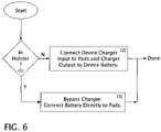
- FIG. 6is a logic flow chart of the operation of the handheld electronic device described herein;
- FIG. 7is a block circuit diagram of the charging circuit of the handheld electronic device described herein;
- FIG. 8is a logic flow chart of the circuitry of the holder of the device described herein;
- FIG. 9is a block circuit diagram of the holder charging circuit of the device described herein.
- FIGS. 1 and 2An improved electronic device 4 is indicated generally in FIGS. 1 and 2 .
- the electronic device 4includes an improved handheld electronic device 8 and an improved holder 12 .
- the holder 12cooperates with the handheld electronic device 8 , as will be set forth in greater detail below. Examples of handheld electronic devices are disclosed in U.S. Pat. Nos. 6,452,588 and 6,489,950.
- the handheld electronic device 8includes a housing 16 , a display 20 , a processor 24 , a keyboard 28 , and a first battery 32 .
- the processor 24can be any of a wide variety of processors, such as, without limitation, a microprocessor ( ⁇ P).
- the processor 24is operable to receive inputs from the keyboard 28 and to provide processed output to the display 20 .
- the first battery 32provides power to the processor 24 and the display 20 .
- the handheld electronic device 8additionally includes a plurality of contacts 36 that are disposed on the housing 16 and are electrically connected with the battery 32 .
- the holder or holster 12includes a housing 40 formed with a cavity 44 , a first charging apparatus 48 , a second battery 52 and a second charging apparatus 56 (shown in FIG. 4 ).
- the first charging apparatus 48 and the second charging apparatus 56are both electrically connected with the second battery 52 .
- the holder 12additionally includes a plurality of second contacts 60 ( FIG. 4 ) disposed on the housing 40 within the cavity 44 and, in the embodiment depicted in FIGS. 1 and 2 , includes a power cord 64 that is electrically connectable with a suitable external power source 68 ( FIG. 4 ) which, in the present example, is a 110 volt AC power source, though, as will be appreciated in the art, the external power source 68 may also be a USB port.
- the second contacts 60are electrically connectable with the first contacts 36 of the handheld electronic device 8 .
- the housing 40includes an opening 72 formed therein that enables the user to gain access to the keyboard 28 and observe the display 20 when the handheld device 8 is received in a first orientation ( FIG. 1 ) in the housing 40 .
- the embodiments described hereinaddress the limited battery life of handheld devices by supplementing the charge stored in the handheld battery 32 with charge stored in an additional battery 52 built into the holder or holster 12 through the built in charging contacts 36 of the handheld electronic device 8 and the built in mating charging contacts 60 of the holder 12 .
- the embodiments described hereinalso do away with the problem of a user charging and carrying two separate batteries by effectively hiding the second battery 52 within an accessory, in this case the holster 12 .
- New flexible battery technologieswill allow the secondary battery to be built into plastic holsters or be woven into leather holsters.
- the embodiments described hereininclude a second battery 52 sealed within the holster or holder 12 to provide additional charge to the primary handheld battery 32 through the charge contacts 36 and 60 should the primary battery 32 fall below a preset charge level.
- an algorithmwhich controls the charging and discharging of the secondary battery 52 without the use of charging port 64 on the holster 12 .
- the object of this embodimentis to have a battery 52 in the holster 12 that will act to supplement the device battery 32 , thereby increasing the apparent operating time of the device.
- the holster battery 52should be thin so as not to make the holster 12 bulky.
- Li-polymer cellssatisfy this criterior. They can be made very thin, and yet have a very large area (for increased energy storage capacity), and they are quite flexible. Secondly, the modifications to the device should be minimal. Thirdly, the brunt of the cost of the modification should be borne by the holster side 12 so as not to saddle those users that don't want to bear the cost of this improvement. Fourthly, the holster battery 52 should meet all safety requirements.
- the secondary battery 52would be a fraction of the size of the primary battery 32 , i.e. about 30%. This will, in most instances, permit a user to obtain an additional day or two of use before the handheld electronic device has to be recharged from an external source. It is known that longer battery life improves the user's experience. Unfortunately, improving the technology of the battery or providing a replaceable battery increases the device cost. On the other hand, providing a higher capacity battery would increase the weight and size factors. While optimize software decreases device consumption it is effective up to a certain point.
- the secondary battery 52 in the holster 12is at least approximately 1 ⁇ 3 larger than the operational battery 32 in the electronic handheld device 8 so that a smaller operational battery 32 with a size and capacity of a about 1 ⁇ 3 of the current battery can be used.
- the operational battery 32is installed on the handheld electronic device 8 to maintain it while the user is effectively working.
- the supplementary or secondary battery 52is integrated in the holster 12 while the device 8 is in the holster 12 it would consume power from the supplementary battery 52 through power connectors 36 and 60 located in the bottom or back of the handheld electronic device 8 .
- the operational battery 32would be charged at the same time through these same contacts 36 and 60 .
- the average deviceis in its holster approximately 95% of the time so the capacity of the operational battery that is residing on the device does not need to be as high.
- the battery residing on the holstercan be extended in capacity since its weight would not contribute to the handheld devices weight under this arrangement. If you take the battery out of a handheld electronic device such as the BlackBerry device and hold the device in your hand it feels surprisingly light.
- the BlackBerry deviceitself weighs 136 grams. The battery adds an additional 26 grams to the weight. Thus, in this embodiment the weight can be minimized while extending the battery life.
- the userwould need to charge only the holster.
- the battery 32 residing on the handheld electronic device 8would charge itself from the holsters battery 52 .
- the battery 32 on the handheld electronic device 8does not need to be removable.
- the battery 52 on the holster 12is discharged and the user wants to get her/his device working right away then he/she just takes another holster—a procedure much easier then changing the battery (and the device wont even be restarted). In this way an effective removable battery is achieved in a more cost effective and user friendly way.
- the overall battery life of the devicecan be improved and the weight of the device can be decreased. Whether the larger of the two batteries 32 and 52 is incorporated in the holder 12 or handheld device 8 will depend on the nature of the handheld device and the relative times the device is situated in and out of the holder 12 .
- the primary battery 32 on the handheld electronic device 8may be used to charge the holster battery 52 each time the handheld electronic device 8 is placed within its holster.
- a preselected amount of chargefor example 100 mAhr (about 10% of the capacity of a typical handheld battery is transferred from the handheld electronic device 8 to the holster battery 52 each time the handheld electronic device 8 is placed within the holster 12 , to conserve power in the handheld electronic device 8 .
- the handheld electronic device 8may be separately charged from an external source, for example, when it is placed in a docking station.
- the charge algorithm for the electronic device 4is as follows:
- FIGS. 6 and 7respectively show the logic and circuitry modifications that are applied to the handheld electronic device 8 to implement this embodiment. From FIG. 6 it can be appreciated that the device detects whether it is holstered or not. This is readily done with handheld electronic devices 8 such as a BlackBerry by the use of a magnetic reed switch inside the device that detects a magnetic field generated by a small permanent magnet inside the holster. When the handheld electronic device 8 is in the holster 12 , the battery terminals 36 are made directly accessible to the electronic device “charging” pads 60 . Otherwise the device charging pads act just as they would normally and that is to be normal charging pads, such as for cradle charging. The logic for this operation is illustrated in FIG.
- FIG. 7a block diagram of the battery charging circuit for the handheld electronic device 8 is shown in FIG. 7 .
- the charging pads 36are connected directly to the battery 32 through a protection circuit module 76 which is an integral part of the battery pack 32 .
- the protection circuit module 76protects the battery on the handheld device 8 from overcharging.
- the reed switch 72is low, that is position B the handheld electronic device 8 battery charger 48 is interposed between the charging pads 36 and the battery pack 32 .
- the circuit diagram in FIG. 9implements the flow diagram illustrated in FIG. 8 .
- Switch SW 1 and SW 2perform the DC-DC converter/charger input/output reversing functions and are respectively connected to the input and the output of DC-DC converter/charger 78 .
- Comparators COMP 1 and COMP 2detect the state of the handheld electronic device battery 32 . When the voltage is above the lower threshold level as inputed from the voltage divider circuit R 2 , R 3 and R 4 , COMP 2 outputs high. When the voltage is above the upper threshold, that is in this example 3.8 V, COMP 1 turns high. In between, COMP 1 will be low and COMP 2 will be high. There cannot be a case where COMP 1 is high and COMP 2 is low.
- COMP 1when the battery is near full COMP 1 will be high and COMP 2 will be high enabling gate 84 to provide a high input to the SW 3 switch input 88 .
- the high inputcloses the SW 3 switch and delivers a high output to the control input terminal of SW 1 and SW 2 which moves both switches to connect terminal A so that the handheld electronic device 8 charges the holster battery 52 .
- the output of COMP 1When the handheld electronic device battery 32 is in its mid range, identified in Paragraph 2 immediately above, the output of COMP 1 will be low and the output of COMP 2 will be high providing a low output from the gate 84 to the control input terminal 88 of switch SW 3 .
- the low inputopens the switch and opens circuits both SW 1 and SW 2 to the NO position and no charge sharing occurs.
Landscapes
- Engineering & Computer Science (AREA)
- Manufacturing & Machinery (AREA)
- Chemical & Material Sciences (AREA)
- Chemical Kinetics & Catalysis (AREA)
- Electrochemistry (AREA)
- General Chemical & Material Sciences (AREA)
- Power Engineering (AREA)
- Charge And Discharge Circuits For Batteries Or The Like (AREA)
- Power Sources (AREA)
- Secondary Cells (AREA)
Abstract
Description
- 1. If a fully charged
handheld device 8 is placed in theholster 12 with a dischargedsecondary battery 52, thehandheld device 8 will allow theholster battery 52 to trickle charge thehandheld battery 32 through thecharge contacts primary battery 32. Trickle charging is defined as charging at a small portion of the maximum specified charge rate for a particular battery. Each time a fully charged device is inserted within theholster 12, a preset amount of charge is transferred from theprimary battery 32 to the secondary battery under conditions where the secondary battery is to be charged. If the user does not recharge the handheld before theprimary battery 32 fully discharges, theholster battery 52 will return the battery charge before theprimary battery 32 is fully discharged. - 2. Alternatively, the algorithm allows the
battery 52 in theholster 12 to be charged when theelectronic device 4 is attached to a USB port or 110 volt external source and charge both theprimary battery 32 and thesecondary battery 52 while the handheldelectronic device 8 is in theholster 12. The charge states set forth in theabove Paragraph 1 and thisParagraph 2 may be set in a settings menu on the handheldelectronic device 8. - 3. After several full charge insertions of the handheld
electronic device 8 into theholder 12, without drain of theprimary battery 32 below a set level, which is preferably, substantially equal to the full charge level of the primary battery, thesecondary battery 52 will contain a full charge and will no longer take charge from a fully chargedprimary battery 32. - 4. During travel, or when the user is away from a charge source for an extended period, and the handheld battery reaches a preset highly discharged level, such as one bar on the screen, the handheld
electronic device 8 can request charge from thesecondary battery 52 to partially recharge thebattery 32 on the handheldelectronic device 8. In this event, with a reasonable efficiency of transfer of energy, the user may gain upwards of one or two days of use.
- 1. If a fully charged
- 1. The circuit in the
holder 12 determines if the handheldelectronic device battery 32 can provide some charge to charge up theholster battery 52. This is primarily done by measuring the voltage of the handheldelectronic device battery 32. If it is high enough (that is around 3.8 V+, meaning that the device battery is itself fully charged), then this condition is TRUE. In this case an internal (to the holster12) DC-DC converter/charger is used to leak off some charge to charge up the holster battery Up to 10% of the device battery's charge is a reasonable amount to be leaked off for this purpose. The DC-DC converter is needed because most chargers need a somewhat higher voltage at their inputs than what they will provide at their outputs. So, to fully charge up a Li-Ion or Lithium polymer battery to 4.2 V, typical chargers need at least 5.0 V. Since the power source itself is a Li-Ion battery, there is a need for a DC-DC conversion to boost up the charger input. - 2. If the
handheld device battery 32 is in between fully charged and near empty (between approximately 3.8 V to 3.4 V) then the handheldelectronic device 8 can neither provide charge to the holster, nor does it need a boost from the holster and thepads 60 are disconnected from thebattery 32. In this case the battery may have reached this stage from the stage described inParagraph 1 above, or it may already be in this state at the moment when it was holstered. In the first case, this stage provides a mechanism to stop charging in accordance withParagraph 1 immediately above without having theholster 12 immediately switch back and forth between that set forth inParagraph 1 above and that provided inParagraph 3 immediately below. - 3. If the handheld
electronic device battery 32 is very low, then theholster battery 52 will give back some of its charge. Theholster battery 52 itself should not give back so much of its charge that it drains itself beyond its limits. This is accomplished through the protection circuit module (PCM) which prevents theholster battery 52 from over discharging and short circuits, etc. If the holster battery has enough charge, then the direction of the DC-DC converter/charger is changed, and theholster battery 52 charges thedevice battery 32, until the latter reaches the threshold set forth inParagraph 2 immediately above. In this case the charging will stop.
- 1. The circuit in the
| TABLE 1 | |||||
| State | Comp1 | Comp2 | SW3 | SW3 | Action |
| Near Full | High | High | High | High | Device charges |
| holster | |||||
| Mid | Low | High | X | Low | No charge |
| sharing | |||||
| Near | Low | Low | Low | High | Holster charges |
| Empty | device | ||||
The X in the Table means that no output is provided since the switch SW3 under those circumstances is open circuited. Accordingly, the apparatus of this embodiment allows a holster to effectively “steal” small of amounts of charged over time from a fully charged handheld electronic device, and hold it in reserve until required by a user, at the very low end of the primary battery charge cycle, for an additional day or two of use. The device described herein also can reduce the weight of the handheld electronic device without compromising the battery capacity.
Claims (12)
Priority Applications (3)
| Application Number | Priority Date | Filing Date | Title |
|---|---|---|---|
| US11/556,547US7554289B2 (en) | 2006-11-03 | 2006-11-03 | Apparatus and method for the power management of operatively connected batteries respectively on a handheld electronic device and a holder for the handheld electronic device |
| US12/470,717US7847514B2 (en) | 2006-11-03 | 2009-05-22 | Apparatus and method for the power management of operatively connected batteries respectively on a handheld electronic device and a holder for the handheld electronic device |
| US12/911,793US7986123B2 (en) | 2006-11-03 | 2010-10-26 | Apparatus and method for the power management of operatively connected batteries respectively on a handheld electronic device and a holder for the handheld electronic device |
Applications Claiming Priority (1)
| Application Number | Priority Date | Filing Date | Title |
|---|---|---|---|
| US11/556,547US7554289B2 (en) | 2006-11-03 | 2006-11-03 | Apparatus and method for the power management of operatively connected batteries respectively on a handheld electronic device and a holder for the handheld electronic device |
Related Child Applications (1)
| Application Number | Title | Priority Date | Filing Date |
|---|---|---|---|
| US12/470,717ContinuationUS7847514B2 (en) | 2006-11-03 | 2009-05-22 | Apparatus and method for the power management of operatively connected batteries respectively on a handheld electronic device and a holder for the handheld electronic device |
Publications (2)
| Publication Number | Publication Date |
|---|---|
| US20080106232A1 US20080106232A1 (en) | 2008-05-08 |
| US7554289B2true US7554289B2 (en) | 2009-06-30 |
Family
ID=39359171
Family Applications (3)
| Application Number | Title | Priority Date | Filing Date |
|---|---|---|---|
| US11/556,547Active2027-07-05US7554289B2 (en) | 2006-11-03 | 2006-11-03 | Apparatus and method for the power management of operatively connected batteries respectively on a handheld electronic device and a holder for the handheld electronic device |
| US12/470,717ActiveUS7847514B2 (en) | 2006-11-03 | 2009-05-22 | Apparatus and method for the power management of operatively connected batteries respectively on a handheld electronic device and a holder for the handheld electronic device |
| US12/911,793ActiveUS7986123B2 (en) | 2006-11-03 | 2010-10-26 | Apparatus and method for the power management of operatively connected batteries respectively on a handheld electronic device and a holder for the handheld electronic device |
Family Applications After (2)
| Application Number | Title | Priority Date | Filing Date |
|---|---|---|---|
| US12/470,717ActiveUS7847514B2 (en) | 2006-11-03 | 2009-05-22 | Apparatus and method for the power management of operatively connected batteries respectively on a handheld electronic device and a holder for the handheld electronic device |
| US12/911,793ActiveUS7986123B2 (en) | 2006-11-03 | 2010-10-26 | Apparatus and method for the power management of operatively connected batteries respectively on a handheld electronic device and a holder for the handheld electronic device |
Country Status (1)
| Country | Link |
|---|---|
| US (3) | US7554289B2 (en) |
Cited By (8)
| Publication number | Priority date | Publication date | Assignee | Title |
|---|---|---|---|---|
| US20090278490A1 (en)* | 2006-11-03 | 2009-11-12 | Research In Motion Limited | Apparatus and method for the power management of operatively connected batteries respectively on a handheld electronic device and a holder for the handheld electronic device |
| US20120088555A1 (en)* | 2010-10-12 | 2012-04-12 | Jianzhong Hu | Wireless charging equipment for mobile phones |
| US20140217989A1 (en)* | 2011-09-02 | 2014-08-07 | Nec Corporation | Battery control system, battery controller, battery control method, and recording medium |
| US10170738B2 (en) | 2008-01-18 | 2019-01-01 | Mophie Inc. | Battery pack for mobile devices |
| US10516431B2 (en) | 2017-11-21 | 2019-12-24 | Mophie Inc. | Mobile device case for receiving wireless signals |
| US11394233B2 (en)* | 2017-02-07 | 2022-07-19 | Charging Energy Partner Gmbh | Device and method for charging a terminal device |
| USD1000555S1 (en)* | 2019-10-16 | 2023-10-03 | Alfio Bucceri | Electronic device holder |
| USD1062602S1 (en)* | 2023-06-12 | 2025-02-18 | Andrew J. Olson | Magnetic battery storage device |
Families Citing this family (32)
| Publication number | Priority date | Publication date | Assignee | Title |
|---|---|---|---|---|
| JP2008131707A (en)* | 2006-11-20 | 2008-06-05 | Nec Tokin Corp | Charger for cellular phone |
| US8368346B2 (en)* | 2007-03-26 | 2013-02-05 | The Gillette Company | Portable energy storage and charging device |
| KR101354798B1 (en)* | 2007-04-03 | 2014-01-23 | 삼성전자주식회사 | Apparatus and method for sensing attachment or detachment of battery in mobile terminal |
| US20080315516A1 (en)* | 2007-06-21 | 2008-12-25 | John Lindel Willis | Card Viewing Device |
| US8037331B2 (en) | 2008-04-28 | 2011-10-11 | Dell Products L.P. | Energy efficient method to wake host system for charging battery powered portable devices via bus powered external i/o ports |
| WO2010094815A1 (en)* | 2009-02-20 | 2010-08-26 | Francisco Lorenzo Esteban Azpiroz | Charger for mobile devices |
| USD613685S1 (en)* | 2009-05-28 | 2010-04-13 | Samsung Electronics Co., Ltd. | Internet wireless phone recharger |
| CN102025001B (en)* | 2009-09-21 | 2013-07-31 | 联想(北京)有限公司 | Terminal and charging and power supplying method thereof |
| JP4783454B2 (en)* | 2009-11-30 | 2011-09-28 | 株式会社東芝 | Power supply device, system, and charge / discharge control method |
| CN101882701B (en)* | 2010-06-25 | 2013-09-11 | 中兴通讯股份有限公司 | Charging method and system |
| US8204551B2 (en)* | 2010-10-19 | 2012-06-19 | Chih Hsing Lee | Attachable battery pack for intelligent cell phone |
| TWI434122B (en)* | 2011-01-21 | 2014-04-11 | Delta Electronics Inc | A magnetic fix structure apply on a projection device |
| US20130038269A1 (en)* | 2011-08-10 | 2013-02-14 | Steven Stilts | Handheld mobile electrical assembly |
| US8710794B2 (en)* | 2011-10-07 | 2014-04-29 | Raytheon Company | Method and apparatus for a battery docking connector having reserve power for hot battery swap |
| WO2013130124A1 (en)* | 2012-02-29 | 2013-09-06 | Deka Products Limited Partnership | System and method for powering a device |
| USD709505S1 (en)* | 2012-04-23 | 2014-07-22 | Samsung Electronics Co., Ltd. | Docking station |
| US9007017B2 (en) | 2012-04-23 | 2015-04-14 | Google Technology Holdings LLC | Intelligent battery management method and device |
| USD716287S1 (en) | 2012-11-03 | 2014-10-28 | Manuel Santiago Ambriz | Handheld electronic device holder |
| US9337661B2 (en)* | 2012-12-27 | 2016-05-10 | Intel Corporation | Power management system and method |
| JP6288913B2 (en)* | 2012-12-28 | 2018-03-07 | キヤノン株式会社 | Electronic device and program |
| CN104114227B (en)* | 2013-02-13 | 2016-08-03 | 韩国哈贝任医学美容仪器有限公司 | Portable High Frequency Therapeutic Device with Built-in Battery |
| JP6060768B2 (en)* | 2013-03-27 | 2017-01-18 | 富士通株式会社 | Terminal device, charging device, terminal support device, terminal charging system, charging method, and charging program |
| CN104142710A (en)* | 2013-05-10 | 2014-11-12 | 深圳富泰宏精密工业有限公司 | Tablet computer protection case and tablet computer protection system applying same |
| WO2015027331A1 (en)* | 2013-08-31 | 2015-03-05 | Claude Cloutier | Holder for an electronic device |
| US20150354763A1 (en)* | 2014-06-09 | 2015-12-10 | Phillip Lanier | Recharging Flashlight Holster |
| US9780588B2 (en)* | 2015-06-26 | 2017-10-03 | Intel Corporation | Electronic device to be directly charged by a charging device |
| KR102512986B1 (en) | 2015-11-17 | 2023-03-22 | 삼성전자주식회사 | Electronic system and electronic device |
| US20170207639A1 (en)* | 2016-01-15 | 2017-07-20 | Ranch Systems Llc | Virtual battery comprising individually managed energy storage units |
| TWI597916B (en)* | 2016-08-05 | 2017-09-01 | 緯創資通股份有限公司 | Charging Circuit and Electronic Device |
| CN111162571B (en)* | 2018-11-08 | 2022-03-11 | Oppo广东移动通信有限公司 | A charging circuit and electronic equipment |
| JP7368711B2 (en)* | 2019-10-18 | 2023-10-25 | アイコム株式会社 | Charging holder for electronic devices |
| US12113373B2 (en)* | 2020-12-17 | 2024-10-08 | Apple Inc. | Wireless power system with charging alerts |
Citations (18)
| Publication number | Priority date | Publication date | Assignee | Title |
|---|---|---|---|---|
| EP0274279A2 (en) | 1987-01-08 | 1988-07-13 | Nec Corporation | Holding structure for a paging receiver having extra functions |
| US5353017A (en) | 1991-08-06 | 1994-10-04 | Matsushita Electric Industrial Co., Ltd. | Call selective receiver built in with vibrator |
| US5551079A (en) | 1992-04-30 | 1996-08-27 | Silcom Research Limited | Radio pager holster assembly |
| US5914585A (en) | 1996-02-20 | 1999-06-22 | Norand Corporation | Power sharing in computing systems with a plurality of electronic devices |
| WO1999053621A1 (en) | 1998-04-14 | 1999-10-21 | Qualcomm Incorporated | Method and system for interfacing a wireless communication device with an accessory |
| US6184654B1 (en) | 1998-07-28 | 2001-02-06 | Double-Time Battery Corporation | Wearable docking-holster system, with energy management, to support portable electronic devices |
| GB2352887A (en) | 1999-06-17 | 2001-02-07 | Vtech Communications Ltd | Cordless phone with battery backup |
| US20030030412A1 (en) | 2001-08-10 | 2003-02-13 | Seiko Epson Corporation | Power control circuit, electronic instrument, and charging method |
| US20030155887A1 (en) | 2002-02-15 | 2003-08-21 | Bourilkov Jordan T. | Hybrid power supply |
| GB2386267A (en) | 2002-03-05 | 2003-09-10 | Nec Technologies | Holster with battery for portable equipment |
| US20030178967A1 (en) | 2002-03-21 | 2003-09-25 | Khatri Nizam Issa | Apparatus and method for the power management of operatively connected modular devices |
| US20030197485A1 (en)* | 2002-04-22 | 2003-10-23 | Michael Miller | Battery adapter |
| DE10305477A1 (en) | 2003-02-11 | 2004-08-26 | Kastriot Merlaku | Mobile phone has a power output for supplying external devices and or charging their batteries from its own battery, a connection for an external battery and an integral torch |
| EP1569315A1 (en) | 2004-02-26 | 2005-08-31 | Research In Motion Limited | Method and apparatus for a dual battery configuration of a hendheld device and holder |
| US20050189913A1 (en) | 2004-02-26 | 2005-09-01 | Vitanov Kamen B. | Electronic device including handheld electronic device with dual battery configuration, and associated method |
| EP1600907A1 (en) | 2004-05-27 | 2005-11-30 | Research In Motion Limited | Handheld electronic device including vibrator having different vibration intensities and method for vibrating a handheld electronic device |
| JP2006260183A (en) | 2005-03-17 | 2006-09-28 | Canon Inc | E-mail terminal device |
| US20060226805A1 (en) | 2005-04-11 | 2006-10-12 | Tsung-I Yu | Mobile battery-charging container |
Family Cites Families (1)
| Publication number | Priority date | Publication date | Assignee | Title |
|---|---|---|---|---|
| US7554289B2 (en)* | 2006-11-03 | 2009-06-30 | Research In Motion Limited | Apparatus and method for the power management of operatively connected batteries respectively on a handheld electronic device and a holder for the handheld electronic device |
- 2006
- 2006-11-03USUS11/556,547patent/US7554289B2/enactiveActive
- 2009
- 2009-05-22USUS12/470,717patent/US7847514B2/enactiveActive
- 2010
- 2010-10-26USUS12/911,793patent/US7986123B2/enactiveActive
Patent Citations (18)
| Publication number | Priority date | Publication date | Assignee | Title |
|---|---|---|---|---|
| EP0274279A2 (en) | 1987-01-08 | 1988-07-13 | Nec Corporation | Holding structure for a paging receiver having extra functions |
| US5353017A (en) | 1991-08-06 | 1994-10-04 | Matsushita Electric Industrial Co., Ltd. | Call selective receiver built in with vibrator |
| US5551079A (en) | 1992-04-30 | 1996-08-27 | Silcom Research Limited | Radio pager holster assembly |
| US5914585A (en) | 1996-02-20 | 1999-06-22 | Norand Corporation | Power sharing in computing systems with a plurality of electronic devices |
| WO1999053621A1 (en) | 1998-04-14 | 1999-10-21 | Qualcomm Incorporated | Method and system for interfacing a wireless communication device with an accessory |
| US6184654B1 (en) | 1998-07-28 | 2001-02-06 | Double-Time Battery Corporation | Wearable docking-holster system, with energy management, to support portable electronic devices |
| GB2352887A (en) | 1999-06-17 | 2001-02-07 | Vtech Communications Ltd | Cordless phone with battery backup |
| US20030030412A1 (en) | 2001-08-10 | 2003-02-13 | Seiko Epson Corporation | Power control circuit, electronic instrument, and charging method |
| US20030155887A1 (en) | 2002-02-15 | 2003-08-21 | Bourilkov Jordan T. | Hybrid power supply |
| GB2386267A (en) | 2002-03-05 | 2003-09-10 | Nec Technologies | Holster with battery for portable equipment |
| US20030178967A1 (en) | 2002-03-21 | 2003-09-25 | Khatri Nizam Issa | Apparatus and method for the power management of operatively connected modular devices |
| US20030197485A1 (en)* | 2002-04-22 | 2003-10-23 | Michael Miller | Battery adapter |
| DE10305477A1 (en) | 2003-02-11 | 2004-08-26 | Kastriot Merlaku | Mobile phone has a power output for supplying external devices and or charging their batteries from its own battery, a connection for an external battery and an integral torch |
| EP1569315A1 (en) | 2004-02-26 | 2005-08-31 | Research In Motion Limited | Method and apparatus for a dual battery configuration of a hendheld device and holder |
| US20050189913A1 (en) | 2004-02-26 | 2005-09-01 | Vitanov Kamen B. | Electronic device including handheld electronic device with dual battery configuration, and associated method |
| EP1600907A1 (en) | 2004-05-27 | 2005-11-30 | Research In Motion Limited | Handheld electronic device including vibrator having different vibration intensities and method for vibrating a handheld electronic device |
| JP2006260183A (en) | 2005-03-17 | 2006-09-28 | Canon Inc | E-mail terminal device |
| US20060226805A1 (en) | 2005-04-11 | 2006-10-12 | Tsung-I Yu | Mobile battery-charging container |
Cited By (12)
| Publication number | Priority date | Publication date | Assignee | Title |
|---|---|---|---|---|
| US20090278490A1 (en)* | 2006-11-03 | 2009-11-12 | Research In Motion Limited | Apparatus and method for the power management of operatively connected batteries respectively on a handheld electronic device and a holder for the handheld electronic device |
| US7847514B2 (en)* | 2006-11-03 | 2010-12-07 | Research In Motion Limited | Apparatus and method for the power management of operatively connected batteries respectively on a handheld electronic device and a holder for the handheld electronic device |
| US20110037426A1 (en)* | 2006-11-03 | 2011-02-17 | Research In Motion Limited | Apparatus and method for the power management of operatively connected batteries respectively on a handheld electronic device and a holder for the handheld electronic device |
| US7986123B2 (en) | 2006-11-03 | 2011-07-26 | Research In Motion Limited | Apparatus and method for the power management of operatively connected batteries respectively on a handheld electronic device and a holder for the handheld electronic device |
| US10170738B2 (en) | 2008-01-18 | 2019-01-01 | Mophie Inc. | Battery pack for mobile devices |
| US10559788B2 (en) | 2008-01-18 | 2020-02-11 | Mophie Inc. | Battery pack for mobile devices |
| US20120088555A1 (en)* | 2010-10-12 | 2012-04-12 | Jianzhong Hu | Wireless charging equipment for mobile phones |
| US20140217989A1 (en)* | 2011-09-02 | 2014-08-07 | Nec Corporation | Battery control system, battery controller, battery control method, and recording medium |
| US11394233B2 (en)* | 2017-02-07 | 2022-07-19 | Charging Energy Partner Gmbh | Device and method for charging a terminal device |
| US10516431B2 (en) | 2017-11-21 | 2019-12-24 | Mophie Inc. | Mobile device case for receiving wireless signals |
| USD1000555S1 (en)* | 2019-10-16 | 2023-10-03 | Alfio Bucceri | Electronic device holder |
| USD1062602S1 (en)* | 2023-06-12 | 2025-02-18 | Andrew J. Olson | Magnetic battery storage device |
Also Published As
| Publication number | Publication date |
|---|---|
| US7986123B2 (en) | 2011-07-26 |
| US7847514B2 (en) | 2010-12-07 |
| US20090278490A1 (en) | 2009-11-12 |
| US20080106232A1 (en) | 2008-05-08 |
| US20110037426A1 (en) | 2011-02-17 |
Similar Documents
| Publication | Publication Date | Title |
|---|---|---|
| US7554289B2 (en) | Apparatus and method for the power management of operatively connected batteries respectively on a handheld electronic device and a holder for the handheld electronic device | |
| US8179093B2 (en) | Handheld electronic device with holster having a notification device | |
| ES2278602T3 (en) | RECHARGEABLE BATTERY PACKAGES. | |
| US7479759B2 (en) | Electronic device including handheld electronic device with dual battery configuration, and associated method | |
| US20090115367A1 (en) | Portable battery DC charger | |
| US20080284370A1 (en) | Portable Battery Operated Power Supply | |
| EP1610438A2 (en) | Mobile charger | |
| CA2640903C (en) | Electronic device, including handheld electronic device with intelligent holster | |
| US7248902B2 (en) | Multi-mode power supply device of wireless earphone | |
| CN209948723U (en) | Fast wireless portable power source that fills with two-way function of charging | |
| CA2498080C (en) | Electronic device including handheld electronic device with dual battery configuration, and associated method | |
| CA2609864C (en) | Electronic device, including handheld electronic device, with dual battery configuration and associated method | |
| US20060250108A1 (en) | Supplemental battery for a portable electronic device | |
| CN214754601U (en) | Energy storage data line | |
| WO2008007965A1 (en) | Battery recharging and supporting device | |
| KR20080004844U (en) | Portable Cradle Charger for Mobile Devices | |
| JP2006141187A (en) | Power tank | |
| KR200274609Y1 (en) | Cellular phone battery equipped with recharger using solar cell panel | |
| KR20060050084A (en) | Mobile phone and battery charger | |
| CN113271809B (en) | Power screen protector | |
| WO2007035103A1 (en) | Rechargeable back-up battery device | |
| KR20170138120A (en) | Supplementary battery for Bluetooth mobile phone | |
| HK1079346A (en) | Method and apparatus for a dual battery configuration of a hendheld device and holder | |
| KR20020034126A (en) | Cellular phone battery equipped with recharger using solar cell panel |
Legal Events
| Date | Code | Title | Description |
|---|---|---|---|
| AS | Assignment | Owner name:RESEARCH IN MOTION LIMITED, ONTARIO Free format text:ASSIGNMENT OF ASSIGNORS INTEREST;ASSIGNORS:IDZIK, JACEK S.;LITINGTUN, SIONG;REEL/FRAME:018507/0439 Effective date:20061102 | |
| STCF | Information on status: patent grant | Free format text:PATENTED CASE | |
| FPAY | Fee payment | Year of fee payment:4 | |
| AS | Assignment | Owner name:BLACKBERRY LIMITED, ONTARIO Free format text:CHANGE OF NAME;ASSIGNOR:RESEARCH IN MOTION LIMITED;REEL/FRAME:037861/0215 Effective date:20130709 | |
| FPAY | Fee payment | Year of fee payment:8 | |
| MAFP | Maintenance fee payment | Free format text:PAYMENT OF MAINTENANCE FEE, 12TH YEAR, LARGE ENTITY (ORIGINAL EVENT CODE: M1553); ENTITY STATUS OF PATENT OWNER: LARGE ENTITY Year of fee payment:12 | |
| AS | Assignment | Owner name:MALIKIE INNOVATIONS LIMITED, IRELAND Free format text:ASSIGNMENT OF ASSIGNORS INTEREST;ASSIGNOR:BLACKBERRY LIMITED;REEL/FRAME:064104/0103 Effective date:20230511 | |
| AS | Assignment | Owner name:MALIKIE INNOVATIONS LIMITED, IRELAND Free format text:NUNC PRO TUNC ASSIGNMENT;ASSIGNOR:BLACKBERRY LIMITED;REEL/FRAME:064269/0001 Effective date:20230511 |