US7553305B2 - Push-pull wire anchor - Google Patents
Push-pull wire anchorDownload PDFInfo
- Publication number
- US7553305B2 US7553305B2US11/149,079US14907905AUS7553305B2US 7553305 B2US7553305 B2US 7553305B2US 14907905 AUS14907905 AUS 14907905AUS 7553305 B2US7553305 B2US 7553305B2
- Authority
- US
- United States
- Prior art keywords
- flexible element
- skirt
- deflectable
- catheter
- distal end
- Prior art date
- Legal status (The legal status is an assumption and is not a legal conclusion. Google has not performed a legal analysis and makes no representation as to the accuracy of the status listed.)
- Active, expires
Links
- 0C1CC*CC1Chemical compoundC1CC*CC10.000description1
- WJLOWVJIIAEJCY-UHFFFAOYSA-NC=[O]CCCN=OChemical compoundC=[O]CCCN=OWJLOWVJIIAEJCY-UHFFFAOYSA-N0.000description1
- YEJFTVJRCUPIOV-UHFFFAOYSA-NCCC1CNC1Chemical compoundCCC1CNC1YEJFTVJRCUPIOV-UHFFFAOYSA-N0.000description1
Images


Classifications
- A—HUMAN NECESSITIES
- A61—MEDICAL OR VETERINARY SCIENCE; HYGIENE
- A61M—DEVICES FOR INTRODUCING MEDIA INTO, OR ONTO, THE BODY; DEVICES FOR TRANSDUCING BODY MEDIA OR FOR TAKING MEDIA FROM THE BODY; DEVICES FOR PRODUCING OR ENDING SLEEP OR STUPOR
- A61M25/00—Catheters; Hollow probes
- A61M25/01—Introducing, guiding, advancing, emplacing or holding catheters
- A61M25/0105—Steering means as part of the catheter or advancing means; Markers for positioning
- A61M25/0133—Tip steering devices
- A61M25/0147—Tip steering devices with movable mechanical means, e.g. pull wires
- A61M2025/015—Details of the distal fixation of the movable mechanical means
- Y—GENERAL TAGGING OF NEW TECHNOLOGICAL DEVELOPMENTS; GENERAL TAGGING OF CROSS-SECTIONAL TECHNOLOGIES SPANNING OVER SEVERAL SECTIONS OF THE IPC; TECHNICAL SUBJECTS COVERED BY FORMER USPC CROSS-REFERENCE ART COLLECTIONS [XRACs] AND DIGESTS
- Y10—TECHNICAL SUBJECTS COVERED BY FORMER USPC
- Y10T—TECHNICAL SUBJECTS COVERED BY FORMER US CLASSIFICATION
- Y10T29/00—Metal working
- Y10T29/49—Method of mechanical manufacture
- Y10T29/49826—Assembling or joining
- Y10T29/49906—Metal deforming with nonmetallic bonding
- Y—GENERAL TAGGING OF NEW TECHNOLOGICAL DEVELOPMENTS; GENERAL TAGGING OF CROSS-SECTIONAL TECHNOLOGIES SPANNING OVER SEVERAL SECTIONS OF THE IPC; TECHNICAL SUBJECTS COVERED BY FORMER USPC CROSS-REFERENCE ART COLLECTIONS [XRACs] AND DIGESTS
- Y10—TECHNICAL SUBJECTS COVERED BY FORMER USPC
- Y10T—TECHNICAL SUBJECTS COVERED BY FORMER US CLASSIFICATION
- Y10T29/00—Metal working
- Y10T29/49—Method of mechanical manufacture
- Y10T29/49826—Assembling or joining
- Y10T29/49908—Joining by deforming
- Y10T29/49925—Inward deformation of aperture or hollow body wall
Definitions
- fracturing the wireprevents transmission of pushing and pulling forces to the deflectable distal end portion.
- Failure of the push-pull wirecan complicate a medical procedure. For instance, the catheter must be withdrawn through curving vasculature, possibly in a deflected position created prior to fracture of the push-pull wire. The deflected catheter can snag within the vasculature and complicate the extraction. Further, the catheter must be exchanged with another deflectable catheter and the vasculature traversed again to complete the medical procedure.
- a push-pull wire anchorthat overcomes the shortcomings of previous designs. What is further needed is a push-pull wire anchor that substantially prevents fracture of the push-pull wire and puncturing of a catheter by a fractured push-pull wire.
- the tension strength and compression strength of the flexible element and the at least one skirtare at least as strong as the encapsulant tension strength and compression strength.
- the skirtincludes at least one recess (e.g., holes, corrugations, grooves or the like) dimensioned and configured to receive the encapsulant, in yet another option.
- At least one weldcouples the flexible element distal portion to the deflectable distal end portion, and the at least one weld is distal to the at least one skirt.
- the at least one skirtincludes a flared portion.
- the flared portionincludes at least one recess (e.g., hole, corrugation or the like) optionally.
- At least one of the skirt and the flexible element distal portioninclude at least one projection. At least one of the skirt and the distal portion include at least one recess sized and shaped to receive the at least one projection, optionally. In yet another option, the at least one projection extends from the skirt and engages against the flexible element distal portion substantially immobilizing the at least one skirt relative to the flexible element. In still another option, the skirt includes knurling, brazing dots or the like.
- a method for making a deflectable catheterincludes positioning a flexible element along a catheter liner. A distal portion of the flexible element extends along at least a portion of a deflectable distal end portion of the catheter liner. At least one skirt is coupled to the distal portion, and the at least one skirt extends at least part way around the flexible element distal portion. The method further includes positioning an encapsulant around at least the flexible element distal portion and the deflectable distal end portion. The encapsulant is squeezed around the flexible element distal portion and the skirt, and the encapsulant forms at least a portion of a sidewall of the deflectable distal end portion and at least the skirt is within the sidewall. The encapsulant is adapted to transmit pushing and pulling forces from the at least one skirt to the deflectable distal end portion. The tension strength and compression strength of the flexible element and the at least one skirt are at least as strong as the encapsulant tension strength and compression strength.
- the methodincludes substantially preventing a puncture of the encapsulant by the flexible element (e.g., the encapsulant grasps the skirt and the skirt is coupled to the flexible element).
- a marker bandis coupled substantially adjacent to the deflectable distal end portion. The marker band is distal relative to the skirt. The flexible element distal portion is welded to the marker band.
- the methodincludes, in yet another option, substantially preventing fracture of the flexible element adjacent to the marker band.
- the skirtincludes a clamp, and the clamp is deformed to grasp the flexible element distal portion.
- the clampis crimped at a plurality of points along the clamp, optionally.
- the methodincludes, in yet another option, engaging a projection extending from at least one of the skirt and the flexible element distal portion against the other of the skirt and the distal portion.
- engaging the projectionincludes seating the projection within at least one recess sized and shaped to receive the projection, wherein the recess is formed in at least one of the skirt and the flexible element distal portion.
- the methodincludes deforming at least one of the flexible element and the skirt with the projection to form the recess.
- the above described catheterallows for deflection of a deflectable distal end portion while substantially preventing fracture of a flexible element.
- Pushing and pulling forces from the flexible elementare transmitted through the skirt to the encapsulant and the catheter liner at the deflectable distal end portion of the catheter.
- the skirt anchored in the encapsulantfacilitates deflection of the deflectable distal end portion through transmission of the pushing and pulling forces.
- the skirtis integral to the flexible element distal portion.
- the skirt and the flexible elementare disposed along the catheter body proximal to a marker band used to see the tip of the catheter body during procedures (e.g., with fluoroscopy). Proximally positioning the skirt provides additional space to include features, for instance flush openings and the like, positioned between the skirt and marker band.
- the flexible element and the skirthave tension and compression strengths at least as great as the tension and compression strengths of the encapsulant to substantially reduce fracture of the flexible element.
- the catheter bodyis adapted to fail before failure of the flexible element and the skirt, and puncturing of the catheter body is thereby substantially prevented by a fractured element.
- the skirtis coupled to the flexible element distal portion without a weld. Fracturing of the flexible element is thereby substantially reduced because stress is not applied to a weakened annealed region.
- the skirtis localized around the flexible element without extending remotely around the deflectable distal end portion. The skirt thus provides improved strength and durability against failure through shearing.
- the skirtis localized substantially adjacent to the flexible element pushing and pulling forces are not distributed around the catheter body. The deflectable distal end portion thus experiences an improved deflection response with the concentrated pushing and pulling of the flexible element.
- the skirtcooperates with the marker band coupled to the flexible element distal portion.
- the marker bandis coupled to the flexible element distally relative to the skirt.
- the skirtacts as a supplementary anchor and distributes pushing and pulling forces between the marker band and itself. Fracturing of the flexible element adjacent to the marker band (e.g., the annealed region near a weld) is substantially reduced because the pushing and pulling forces are distributed between the skirt and the marker band.
- the skirt embedded in the encapsulantacts to substantially immobilize the fractured flexible element and substantially prevent puncturing of the catheter body.
- the skirtfacilitates continued use of the catheter with a fractured flexible element because the skirt continues to function as an anchor and transmits pushing and pulling forces to the deflectable distal end portion.
- the encapsulantis squeezed around the catheter liner to easily form an outer surface and sidewall of the catheter body and grasp the skirt.
- the skirtis in the sidewall and thereby provides a larger moment to the deflectable distal end portion because it is positioned remotely from the center of the catheter body.
- the encapsulantflows around the skirt and, when hardened, transmits tension and compression forces to the deflectable distal end portion while also acting as the outer surface of the catheter body. Complex manufacturing procedures including drilling and/or forming a pocket for an anchor and injecting an adhesive over the anchor are thereby avoided.
- the skirtis retained along the catheter body and the distal end therefore does not house the skirt and/or the flexible element in a hard tip.
- the distal end of the catheter bodythereby has a soft atraumatic tip.
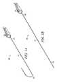
- FIG. 1Ais a perspective view of one example of a catheter in a first deflected position.
- FIG. 1Bis a perspective view of the catheter in a non-deflected position.
- FIG. 1Cis a perspective view of the catheter in a second deflected position.
- FIG. 2is a perspective view of one example of the deflectable distal end portion.
- FIG. 3is a cross-sectional view of one example of a catheter assembly.
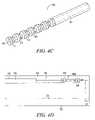
- FIG. 4Ais a partial sectional view of another example of a catheter assembly.
- FIG. 4Bis a partial sectional view of another example of a catheter assembly.
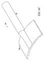
- FIG. 4Cis a perspective view of one example of an anchor.
- FIG. 4Dis a partial sectional view of another example of a catheter assembly.
- FIG. 5Ais a perspective view of another example of an anchor.
- FIG. 5Bis a perspective view of yet another example of an anchor.
- FIG. 6is a cross-sectional view of yet another example of a catheter assembly.
- FIG. 7is a cross-sectional view of still another example of a catheter assembly.
- FIG. 8Ais a perspective view of one example of a catheter assembly.
- FIG. 8Bis a perspective view of one example of an anchor.
- FIG. 8Cis a perspective view of another example of an anchor.
- FIG. 8Dis a perspective view of yet another example of an anchor.
- FIG. 9is a cross-sectional view of one example of a catheter assembly.
- FIG. 10is a cross-sectional view of another example of a catheter assembly.
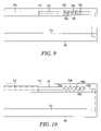
- FIG. 11is a partial sectional view of another example of the deflectable distal end portion.
- FIG. 12is a block diagram illustrating one example of a method for making a catheter assembly.
- FIGS. 1A , B, Cillustrate a deflectable catheter assembly 100 , where FIG. 1A illustrates the deflectable catheter assembly 100 in one articulated position, and FIG. 1C illustrates the catheter assembly in another articulated orientation.
- FIG. 1Billustrates the deflectable catheter assembly 100 in an unarticulated position.
- the deflectable catheter assembly 100includes a catheter body 110 and a handle assembly 150 that houses actuating mechanisms for deflecting the catheter body 110 .
- the handle assembly 150allows for the selectable deflection of a deflectable distal end portion 102 of the catheter body 110 into any number of disparate orientations.
- One example of the handle assembly 150is described in co-pending application Ser. No.
- the actuating mechanismincludes a wheel 104 .
- the wheel 104is rotated to deflect the deflectable distal end portion 102 into the orientations shown in FIGS. 1A , C.
- the handle assembly 150includes a slide, knob, pull ring or the like to facilitate deflection of the deflectable distal end portion 102 .
- the catheter body 110includes a flexible element 200 , for instance a push-pull wire or the like.
- the flexible element 200is constructed with, but is not limited to steel, polymers or the like.
- the flexible element 200is coupled between the actuating mechanisms in the handle assembly 150 ( FIG. 1 ) and the deflectable distal end portion 102 .
- FIGS. 1A , Cwhen tension or compression is applied to the flexible element 200 (e.g., using the wheel 104 ), corresponding pushing or pulling forces are experienced by the deflectable distal end portion 102 causing the deflectable distal end portion 102 to curve in predetermined directions.
- the distal end portion 102is deflected, in one option, to traverse vasculature with the catheter assembly 100 .
- the catheter body 110includes an elongate tubular construction that is flexible yet substantially non-compressible along its length.
- the deflectable catheter body 110extends from a proximal end 106 to the deflectable distal end portion 102 .
- the deflectable distal end portion 102in one option, is adapted to be disposed within a patient.
- the handle assembly 150containing the actuator mechanism coupled to the flexible element 200 ( FIG. 2 ) and the wheel 104 .
- the distal end portion 102is deflected to traverse various branch vessels with the catheter assembly 100 ( FIGS. 1A and 1C ).
- FIG. 2illustrates a partial cut-away of one example of the deflectable distal end portion 102 of the catheter body 110 shown in FIGS. 1A , B, C.
- the catheter body 110includes a catheter liner 202 having a catheter lumen 204 extending therein (e.g., the catheter liner 202 defines the catheter lumen 204 ).
- the catheter lumen 204is sized and shaped to receive a variety of instruments, fluids or the like. In one option, the catheter lumen 204 extends through the catheter body 110 to the handle assembly 150 ( FIG. 1 ).
- the distal end of the catheter liner 202forms at least a portion of the deflectable distal end portion 102 .
- the catheter liner 202includes, but is not limited to, flexible materials with sufficient strength and wear resistance for use in the catheter assembly 100 .
- the catheter liner 202includes a polymer such as polytetrafluoroethylene used under the trademark TEFLON® registered to E.I. Du Pont De Nemours and Company.
- a flexible element duct 206is positioned along the catheter liner 202 , in one option.
- the flexible element duct 206is substantially parallel to the catheter liner 202 and extends along at least a portion of the catheter liner 202 , in another option.
- the flexible element duct 206extends from an intermediate portion 207 of the catheter body 110 (e.g., proximal to the deflectable distal end portion 102 ) toward the proximal end 106 adjacent to the handle assembly 150 ( FIGS. 1A , B, C).
- the distal end 208 of the flexible element duct 206is proximal to a distal tip 210 of the catheter body 110 .
- the flexible element duct 206includes an actuator lumen sized and shaped to receive the flexible element 200 (e.g., the flexible element duct 206 defines the actuator lumen).
- the flexible element 200is slidably coupled with the flexible element duct 206 to facilitate transmission of pushing and pulling forces for deflection of the deflectable distal end portion 102 .
- a distal portion 201 of the flexible element 200extends from the distal end 208 of the flexible element duct 206 toward the distal tip 210 of the catheter body 110 .
- the flexible element distal portion 201extends from the distal end 208 of the duct 206 toward a marker band 212 .
- the marker band 212extends around the catheter liner 202 .
- the marker band 212is coupled to the catheter liner 202 with crimping, adhesives, overmolding or the like.
- the marker band 212is fluoroscopic in still another option, facilitating viewing of the deflectable catheter distal end portion 102 during procedures (e.g., when the catheter body 110 is within vasculature).
- the flexible element distal portion 201is optionally coupled to the marker band 212 .
- the distal portion 201 and the marker band 212are coupled together with, but not limited to, welds, adhesives, mechanical fasteners or the like.
- the catheter liner 202 , flexible element duct 206 , flexible element 200 , and the marker band 212are surrounded by an encapsulant 214 .
- the encapsulant 214includes a biocompatible metal, polymer and the like.
- the encapsulant 214includes a poly-ether-block amide compound such as PEBAX® a trademark registered to the Atofina Corporation.
- the components of the catheter body 110are encapsulated with the encapsulant 214 , optionally, by heating the encapsulant to a molten state and squeezing it around catheter liner 202 , flexible element duct 206 , flexible element 200 and the marker band 212 .
- the encapsulant 214flows around the components, grasps them, and solidifies when cooled to form the catheter body 110 .
- the encapsulant 214forms a sidewall 215 and at least a portion of an outer surface 217 of the catheter body 110 surrounding the catheter lumen 204 .
- At least the flexible element duct 206 and the flexible element 200are contained within the encapsulant 214 and outside of the catheter lumen 204 .
- the encapsulant 214forms the outer surface 217 of at least a portion of the deflectable distal end portion 102 , optionally.
- the encapsulantprovides a smooth outer surface 217 and is easily positioned around the catheter body 110 (e.g., heated and squeezed around the catheter body 110 ). Complex manufacturing procedures including drilling and/or forming a pocket for an anchor and injecting an adhesive over the anchor are thereby avoided.
- the encapsulant 214is squeezed around the catheter liner 202 and the other components with shrink tubing 216 .
- the shrink tubing 216contracts when exposed to heat and squeezes the molten encapsulant 214 around the catheter liner 202 and the other components.
- the shrink tubing 216ensures the encapsulant 214 provides a smooth consistent cross-sectional geometry for the catheter body 110 .
- the shrink tubing 216is constructed with, but not limited to, polymers, such as Fluoro Ethylene Propylene.
- the shrink tubing 216is split and removed from the catheter body 110 after the encapsulant 214 has solidified. As shown in FIG. 2 , the shrink tubing 216 remains coupled around the encapsulant 214 .
- the catheter body 110includes a stiffening member embedded within the encapsulant, such as a braided member 218 .
- the braided member 218includes a stainless steel braid.
- the stiffening memberfacilitates rotation of the deflectable distal end portion 102 from the proximal end 106 . Additionally the stiffening member also assists in preventing the catheter body 110 from collapsing.
- the stiffening memberextends from the proximal end 106 to the deflectable distal end portion 102 .
- the stiffening memberextends form the proximal end 106 to the intermediate portion 207 of the catheter body 110 , in yet another option. In this option, at least a portion of the deflectable distal end portion 102 is free of the stiffening member thereby enhancing the deflection capability of the distal end portion 102 .
- FIG. 2illustrates one example of an anchor, such as a skirt 220 disposed around the distal portion 201 of the flexible element 200 .
- the skirt 220is a separate feature from the marker band 212 .
- the skirt 220is proximal relative to the marker band 212 .
- the skirt 220in one option, is integral to the flexible element 200 .
- the skirt 220is coupled to the flexible element 200 , for example by crimping, disposing projections within recesses, overmolding or the like.
- the skirt 220is thereby substantially immobilized along the flexible element 200 .
- the skirt 220partially extends around the flexible element distal portion 201 .
- the skirt 220extends around the flexible element distal portion 201 approximately 180 degrees.
- the skirt 220extends further (e.g., all the way) or less around the flexible element distal portion 201 .
- the skirt 220provides a larger profile along the flexible element 200 than the element 200 itself.
- the profile of the skirt 220allows the encapsulant 214 to grasp the skirt 220 and thereby easily couple with the flexible element distal portion 201 to allow transmission of pushing and pulling forces to the deflectable distal end portion 102 .
- the skirt 220anchors the flexible element distal portion 201 within the encapsulant 214 . Pushing and pulling forces are thereby transmitted from the skirt 220 through the encapsulant 214 and to the catheter liner 202 facilitating deflection of the deflectable distal end portion 102 .
- the encapsulant 214forms the outer surface 217 of at least a portion of the deflectable distal end portion 102 , optionally.
- the encapsulant 214forms the sidewall 215 of the deflectable distal end portion 102 and the skirt 220 is retained within the sidewall 215 and adjacent to the outer surface 217 . Positioning the skirt 220 within the sidewall 215 and adjacent to the outer surface 217 allows for an increased moment to be applied for deflection of the deflectable distal end portion 102 because the skirt 220 and the flexible element distal portion 201 are positioned remotely from the longitudinal center of the catheter body 110 . Additionally, in still another option, the skirt 220 is fully encapsulated to further enhance transmission of pushing and pulling forces to the deflectable distal end portion 102 . Further, the skirt 220 is retained along the catheter body 110 , in an option, thereby allowing the distal tip 210 to have an atraumatic (i.e., deformable) surface for engaging with vasculature and organs.
- atraumatici.e., deformable
- the skirt 220includes, optionally, additional features (e.g., knurling, projections, grooves, or the like) to further enhance the engagement of the skirt 220 with the encapsulant 214 .
- additional featurese.g., knurling, projections, grooves, or the like
- the skirt 220is coupled to the catheter liner 202 with adhesives, mechanical fasteners, or the like, thereby facilitating transmission of pushing and pulling forces to the deflectable distal end portion 102 .
- the encapsulantgrasps the skirt 220 , the marker band 212 and the catheter liner 202 .
- the pushing and pulling forces from the flexible element 200are transmitted in part from the skirt 220 to the encapsulant 214 and the catheter liner 202 to deflect the catheter body 110 .
- pushing and pulling forcesare transmitted from the flexible element 200 to the marker band 212 , and from the marker band 212 to the encapsulant 214 and the catheter liner 202 .
- the skirt 220acts as a supplementary anchor to the marker band 202 and distributes the pushing and pulling forces between the skirt 220 and the marker band 212 .
- the skirt 220is proximal relative to the marker band 212 , the skirt 220 substantially prevents puncturing of the catheter body 110 with a fractured flexible element 200 that fails near the marker band 212 (e.g., where the element 200 is annealed adjacent a weld or other means of coupling between the element 200 and the marker band 212 ).
- the skirt 220transmits pushing forces to the deflectable distal end portion 102 and substantially prevents longitudinal movement of the fractured flexible element 200 that could otherwise puncture the catheter body 110 and cause injury to surrounding vasculature. Additionally, the skirt 220 allows for at least limited deflection of the catheter body 110 after fracture, facilitating completion of a procedure or removal of the catheter body 110 from vasculature. Moreover, the skirt 220 provides a profile that is localized around the flexible element 200 to minimize shearing stresses on the skirt 220 and enhance the lifespan of the skirt 220 while facilitating deflection of the deflectable distal end portion 102 and immobilization of a fractured flexible element.
- FIG. 3shows one example of the skirt 220 coupled along the flexible element distal portion 201 .
- the skirt 220is at least partially surrounded by the encapsulant 214 and substantially immobilized in the encapsulant 214 . Similar to the example shown in FIG. 2 , the skirt 220 cooperates with the encapsulant 214 to couple the flexible element distal portion 201 to the deflectable distal end portion 102 .
- the marker band 212is encapsulated as well, but not otherwise coupled to the flexible element 200 .
- the skirt 220is a separate feature from the marker band 212 , and relatively proximal to the band 212 . Pushing and pulling forces are thereby transmitted through the skirt 220 to the encapsulant 214 to deflect the distal end portion 102 as shown in FIGS. 1A , C.
- the skirt 220shown in FIG. 3 , is constructed with a deformable material, for instance metals, such as steel, aluminum or the like.
- the skirt 220acts as a clamp and is deformed around the flexible element distal portion 201 by crimping.
- the skirt 220includes a crimped portion 300 that engages against the flexible element distal portion 201 and couples the skirt 220 to the distal portion 201 .
- Crimping the skirt 220 to the distal portion 201substantially immobilizes the skirt 220 relative to the flexible element 200 .
- Crimping the skirt 220 around the flexible element distal portion 201substantially reduces the likelihood of fracturing the flexible element 200 with pushing and pulling forces.
- the skirt 220is not coupled to the flexible element 200 with a weld or other means, and therefore there is no weakened annealed region along the flexible element 200 .
- the strength of the flexible element 200e.g., tensile and compression strengths
- the skirt 220 and the flexible element 200have tension and compression strengths at least as great as the tension and compression strengths of the encapsulant 214 and thereby substantially reduce fracture of the flexible element 200 .
- the catheter body 110( FIGS. 1A-C and 2 ) is adapted to fail before failure of the flexible element 200 and the skirt 220 , thereby substantially preventing puncture of the catheter body 110 by a fractured flexible element 200 .
- the skirt 220includes metals, polymers and the like.
- the skirt 220is coupled to the flexible element distal portion 201 with adhesives, overmolding and the like.
- the skirt 220includes projections 302 , for instance non-crimped segments of the skirt 220 , sized and shaped to extend from the flexible element distal portion 201 .
- the projections 302are securely grasped by the encapsulant 214 and anchored therein to firmly couple the skirt 220 and the flexible element 200 to the deflectable distal end portion 102 .
- the encapsulant 214fills a space defined by the projections 302 to firmly anchor the skirt within the encapsulant.
- the projections 302form a flared conical geometry extending away from the crimped portion 300 of the skirt 220 that receives the encapsulant therein.
- Pushing and pulling forcesare transmitted from the flexible element 200 to the skirt 220 and the projections 302 are securely grasped by the encapsulant 214 .
- the pushing and pulling forcesare transmitted from the skirt 220 and the projections 302 through the encapsulant 214 to the deflectable distal end portion 102 .
- the skirt 220thereby pushes and pulls the deflectable distal end portion 102 to deflect the distal end portion 102 as desired.
- FIGS. 4A , B, Dillustrate examples of skirts 400 A, B, D coupled around the flexible element distal portion 201 extending outside the flexible element duct 206 .
- the skirts 400 A, B, Dare integral to the flexible element distal portion 201 .
- the skirts 400 A, B, Care coupled to the distal portion 201 of the flexible element 200 by crimping, adhesives, overmolding or the like. Where the skirts 400 A, B, D are crimped along the flexible element distal portion 201 , the skirts 400 A, B, D are crimped in a similar manner as skirt 220 ( FIG. 2 ).
- the skirt 400 A shown in FIG. 4Ahas an outer surface 402 including surface roughening, texturing, features or the like, such as knurling 404 .
- the knurling 404provides additional features for the encapsulant 214 to grasp and firmly anchor the skirt 400 A to the deflectable distal end portion 102 .
- the knurling 404assists in substantially immobilizing the skirt 400 A within the encapsulant 214 . Pushing and pulling forces are thereby readily transmitted through the skirt 400 A to deflect the distal end portion 102 through the encapsulant 214 .
- the knurling 404enhances the immobilization of the skirt 400 A and assists in substantially preventing a fractured flexible element 200 from puncturing the catheter body 110 ( FIG. 1 ).
- the knurling 404is formed along the skirt 400 A by molding, crimping, or the like.
- the knurling 404 along the skirt 400 Ais formed with a crimping tool having a working surface with corresponding recesses.
- the skirt outer surface 402assumes a configuration corresponding to the crimping tool (i.e., the knurling 404 is in a pattern corresponding to the recesses).
- the knurling 404is formed on the skirt 400 A without crimping the skirt 400 A to the flexible element distal portion 201 .
- the skirt 400 Ais crimped around the distal portion 201 after forming the knurling 404 .
- the skirt 400 Ais adhered, overmolded or the like to couple the skirt 400 A to the distal portion 201 , in yet another option.
- the knurling 404is formed on the skirt 400 A and the skirt is crimped around the distal portion 201 in one step, optionally.
- FIG. 4Billustrates a skirt 400 B similar in some respects the skirt 400 A shown in FIG. 4A .
- Skirt 400 Bincludes ridges 406 formed along the outer surface 402 of the skirt 400 B.
- the ridges 406provide additional features for the encapsulant 214 to grasp and firmly anchor the skirt 400 B to the deflectable distal end portion 102 .
- the ridges 406enhance the immobilization of the skirt 400 B and assist in substantially preventing a fractured flexible element from puncturing the catheter body 110 (See FIG. 2 ).
- the ridges 406are formed along the skirt 400 B by molding, crimping, or the like.
- the skirt 400 Bis crimped adhered, overmolded or the like to couple the skirt 400 B to the flexible element 200 .
- FIG. 4Cillustrates a skirt 400 C including recesses, for instance, corrugations 410 .
- the corrugations 410provide features for the encapsulant 214 ( FIG. 2 ) to flow into and enhance the grasp of the encapsulant on the skirt 400 C.
- the encapsulant 214 and the skirt 400 Ccooperate to anchor the flexible element distal portion 201 ( FIG. 2 ) in the deflectable distal end portion 102 ( FIG. 2 ).
- the skirt 400 Cin one option, has an annular shape as shown in FIG. 4C and the corrugations 410 extend around the annular perimeter of the skirt 400 C.
- the corrugations 410facilitate transmission of pushing and pulling forces through the skirt 400 C to the encapsulant 214 to deflect the distal end portion 102 .
- the skirt 400 Cis stamped, in one option, to create the corrugations 410 .
- the skirt 400 Cis formed with the corrugations 410 prior to crimping the skirt 400 C to the flexible element distal portion 201 ( FIG. 2 ).
- the skirt 400 Cincludes a flexible element lumen 412 .
- the flexible element distal portion 201is inserted into a non-corrugated portion 412 of the skirt 400 C and the non-corrugated portion 412 is crimped to couple the skirt 400 C with the distal portion 201 .
- the flexible element distal portion 201is inserted into the flexible element lumen 412 and the skirt 400 C is stamped to form the corrugations 410 and couple the skirt 400 C to the flexible element distal portion 201 .
- the flexible element distal portion 201extends through the skirt 400 C and is welded to the marker band 212 ( FIG. 2 ).
- the corrugations 410increase the immobilization of the skirt 400 C and substantially prevent fracturing of the flexible element 200 ( FIG. 2 ).
- the skirt 400 Cprevents a fractured flexible element 200 from puncturing the catheter body 110 .
- FIG. 4Dillustrates a skirt 400 D.
- the outer surface 402 of the skirt 400 Dincludes recesses 408 .
- the recesses 408provide additional features for the encapsulant 214 to flow into and firmly anchor the skirt 400 D to the deflectable distal end portion 102 .
- the recesses 408thereby enhance transmission of pushing and pulling forces through the skirt 400 D to deflect the distal end portion 102 .
- the recesses 408increase the immobilization of the skirt 400 D and substantially prevent a fractured flexible element from puncturing the catheter body 110 ( FIG. 2 ).
- the recesses 408include openings extending through the skirt 400 D.
- the recesses 408are formed along the skirt 400 D by molding, crimping, stamping, drilling, etching, or the like.
- the recesses 408 along the skirt 400 Dare formed with a crimping tool having a working surface with bosses corresponding to the pattern of the recesses 408 .
- the skirt outer surface 402assumes a configuration corresponding to the crimping tool (i.e., the recesses 408 are in a pattern corresponding to the bosses).
- the skirt 400 Dis crimped to form the recesses 408 and couple the skirt 400 D to the flexible element distal portion 201 .
- skirt 400 Dis crimped to form the recesses 408 and crimped again to couple the skirt 400 D to the flexible element 200 .
- the skirt 400 Dis adhered, overmolded or the like to couple the skirt 400 D to the flexible element 200 .
- FIGS. 5A , Bshow examples of skirts 500 A, B including recesses 502 dimensioned and configured to receive encapsulant 214 ( FIG. 2 ).
- the encapsulant 214flows into the recesses 502 and immobilizes the skirt 500 A within the encapsulant 214 .
- the recesses 502allow the encapsulant 214 to grasp the skirt 500 A and facilitate transmission of pushing and pulling forces to the deflectable distal end portion 102 .
- the recesses 502are formed by drilling holes in a pattern along a portion of the skirt 500 A.
- the recesses 502are formed by stamping, etching or the like. As shown in FIG. 5B , additional recesses 502 are formed in the skirt 500 B. The larger number of recesses 502 allow for additional penetration of the encapsulant 214 ( FIG. 2 ) and enhance the immobilization of the skirt 500 B.
- the skirt 500 Ais coupled to the flexible element distal portion 201 ( FIG. 2 ) by inserting the flexible element distal portion 201 at least partially through a flexible element lumen 506 .
- a portion 504 of the skirt 500 Awhich does not have recesses, is crimped around the flexible element distal portion 201 . Crimping the portion 504 provides a strong coupling between the skirt 500 A and the flexible element distal portion 201 .
- the entire skirt 500 Ais crimped around the flexible element distal portion 201 .
- the skirt 500 Ais coupled with the flexible element distal portion 201 so the portion 504 is proximal relative to the recesses 502 and the distal tip 210 of the catheter body 110 ( FIG. 1 ), optionally.
- the skirt 500 Ais coupled so the recesses 502 are proximal relative to the distal tip 210 and the non-recessed portion 504 .
- the skirt 500 Bshown in FIG. 5B , is coupled to the flexible element distal portion 201 in a similar manner as described above.
- the skirts 500 A, Bare constructed with, but not limited to metals, in one option.
- the skirts 500 A, Binclude stainless steel.
- FIG. 6shows another example of a skirt 600 embedded within the encapsulant 214 .
- the deflectable distal end portion 102includes the distal portion 201 of the flexible element 200 extending from the flexible element duct 206 .
- the skirt 600is coupled along the flexible element distal portion 201 .
- the flexible element distal portion 201is not coupled with the marker band 212 .
- the distal portion 201is coupled to the marker band 212 ( FIG. 2 ), for instance, with a weld.
- the skirt 600acts as a clamp and is deformable.
- the skirt 600includes, but is not limited to, metals such as steel, aluminum or the like.
- the skirt 600extends part way around the distal portion 201 of the flexible element 200 .
- the skirt 600extends fully around the distal portion 201 , in yet another option.
- the skirt 600Prior to coupling the skirt 600 with the flexible element distal portion 201 , the skirt 600 has an inner surface 602 sized and shaped to fit around the flexible element 200 and allow positioning of the skirt 600 along the element 200 .
- the inner surface 602has a substantially cylindrical geometry prior to coupling of the skirt 600 to the flexible element 200 .
- the skirt 600is positioned along the flexible element distal portion 201 and deformed (e.g., crimped) to engage against the distal portion 201 .
- the skirt 600is thereby substantially immobilized along the flexible element 200 .
- the skirt 600is deformed at a discrete point to create at least one projection, such as spur 604 .
- the skirt 600is deformed to include four spurs 604 .
- the spurs 604engage the inner surface 602 of the skirt 600 with the flexible element distal portion 201 .
- the flexible element distal portion 201includes projections and the inner surface 602 of the skirt 600 is crimped over the projections to couple the skirt to the distal portion 201 .
- the spurs 604extend into the flexible element 200 and deform the flexible element 600 to define corresponding recesses sized and shaped to receive the spurs 604 .
- the spurs 604extend between individual filars of the flexible element 200 (e.g., a wire with a plurality of steel filars).
- the spurs 604immobilize the skirt 600 along the flexible element 200 without substantially weakening the flexible element 200 .
- the spurs 604allow the skirt 600 to have a substantially enlarged uncrimped profile while only a small portion of the skirt 600 is narrowed to form the spurs 600 .
- the skirt 600When coupled to the flexible element 200 with the spurs 604 , the skirt 600 has a larger profile and improved anchoring within the encapsulant 214 .
- the skirt 600includes additional features, such as knurling, ridges, recesses or the like, as previously described. These additional features provide an even larger profile for the encapsulant 214 to grasp and anchor the skirt 600 , further enhancing transmission of pushing and pulling to the deflectable distal end portion 102 .
- the skirt 600substantially prevents puncturing of the catheter body 110 if the flexible element 200 fractures adjacent to the marker band 212 .
- FIG. 7shows yet another example of a skirt 700 coupled along the distal portion 201 of the flexible element 200 .
- the flexible element distal portion 201is free of welds and is not coupled with the marker band 212 .
- the flexible element distal portion 201is coupled to the marker band 212 (See FIG. 2 ) distally relative to the skirt 700 .
- the distal portion 201is optionally welded to the marker band 212 .
- the skirt 700acts as a clamp and is deformable to engage against the flexible element distal portion 201 .
- the skirt 700includes, but is not limited to, metals such as steel, aluminum or the like.
- the skirt 700is overmolded around the flexible element distal portion 201 to couple the skirt 700 to the flexible element 200 .
- the skirt 700includes, for instance, but is not limited to metals, polymers or the like.
- the skirt 700extends part way around the flexible element distal portion 201 .
- the skirt 700extends fully around the distal portion 201 , in another option.
- the skirt 700includes projections 702 sized and shaped to fit within recesses 704 formed in the flexible element distal portion 201 .
- the ends of the skirt 700are crimped to form the projections 702 .
- the projections 702engage the distal portion 201 and form the recesses 704 .
- the recesses 704are pre-formed in the flexible element distal portion 201 and the projections 702 are positioned within the recesses 704 to engage the skirt 700 to the distal portion 201 .
- the recessesare formed, optionally, by deformation of the flexible element, etching, drilling or the like.
- the skirt 700includes recesses and the flexible element distal portion 201 includes projections sized and shaped to fit within the recesses.
- the skirt 700When coupled to the flexible element distal portion 201 , the skirt 700 is substantially immobilized along the flexible element 200 .
- the skirt 700provides an enlarged profile for the flexible element distal portion 201 and facilitates grasping of the flexible element 200 by the encapsulant 214 .
- the skirt 700includes additional features, such as knurling, ridges, recess or the like, as described above. Additional features present an even larger profile for the encapsulant 214 to anchor the skirt 700 , further enhancing transmission of pushing and pulling to the deflectable distal end portion 102 through the encapsulant 214 .
- the skirt 700substantially prevents puncturing of the catheter body 110 if the flexible element 200 fractures adjacent to the marker band 212 .
- FIG. 8Ashows one example of the deflectable distal end portion 102 including a skirt 800 A having a flared portion 802 A (e.g., a paddle geometry).
- FIGS. 8B , C, Dshow additional examples of skirts 800 B, C, D with flared portions 802 B, C, D having different geometries.
- Each of the flared portions 802 A-Dprovide a large profile for the encapsulant 214 ( FIG. 8A ) to grasp and immobilize the skirts 800 A-D.
- the skirts 800 A-Dprovide improved transmission of pushing and pulling forces to the deflectable distal end portion 102 .
- the flexible element distal portion 201is coupled to a marker band 212 ( FIG.
- the skirts 800 A-Dsubstantially immobilize the flexible element distal portion 201 to prevent puncturing of the catheter body 110 if the flexible element 200 fractures adjacent to the marker band 212 .
- the flared portions 802 A-Dare located distally relative to the flexible element distal portion 201 .
- the flared portions 802 A-Dare coincident with the flexible element distal portion 201 , for instance the tip of the distal portion is disposed within one of the flared portions 802 A-D.
- the skirt 800 Aincludes a flared portion 802 A and a proximal portion 804 .
- the flared portion 802 Aprovides a wide and flat profile extending outside of the profile of the proximal portion 804 to facilitate grasping by the encapsulant 214 .
- the flared portion 802 Ais formed, in one option, by stamping the skirt 800 A in the region distal to the proximal portion 804 . In another option, the flared portion 802 A is formed by molding, machining or the like.
- the skirt 800 Ais optionally stamped with a die that defines the geometry of the flared portion 802 A. Other examples of flared portions are shown in FIGS. 8B , C, D.
- the flared portion 802 B( FIG.
- the skirt 800 Cis formed with a die that projects the flared portion 802 B away from the proximal portion 804 with a curved geometry.
- the curved geometrycomplements the rounded geometry of the deflectable distal end portion 102 .
- the skirt 800 Cis stamped with a die that projects the flared portion 802 C further away from the proximal portion 804 than the flared portion 802 B of skirt 800 B.
- the flared portions 802 B, Cremain substantially adjacent to the proximal portion 804 to substantially minimize shearing of the flared portions 802 B, C.
- the skirts 800 A-Dare constructed with, but not limited to, deformable materials such as metals that maintain the geometries of the flared portions 802 A-D.
- the skirts 800 A-Dinclude stainless steel.
- the flared portion 802 Dis formed with a die that projects the flared portion 802 D away from the proximal portion 804 and also forms at least one recess, such as corrugation 806 .
- the corrugation 806defines a non-annular feature for the flared portion 802 D.
- the profile of the flared portion 802 D including the added feature of the corrugation 806enhances immobilization of the skirt 800 D within the encapsulant ( FIG. 8A ).
- the flared portion 802 D having the corrugation 806transmits pushing and pulling forces to the deflectable distal end portion 102 ( FIG. 8A ).
- the proximal portion 804in one option, extends substantially around the flexible element distal portion 201 and is crimped around the distal portion 201 to couple the skirt 800 A with the flexible element 200 .
- the proximal portion 804extends part way around the flexible element distal portion 201 and is crimped to couple the skirt 800 A with the flexible element 200 .
- the proximal portions 804 of the skirts 800 B, C, Dare crimped to couple the skirts with the flexible element 200 , optionally.
- the skirts 800 A-Dare coupled with the flexible element with other means including, but not limited to, adhesives, molding or the like.
- a deflectable distal end portion 102 including a skirt 900 integral to the flexible element distal portion 201is shown in FIG. 9 .
- the skirt 900includes features, such as knurling 902 , provided to anchor the flexible element distal portion 201 within the encapsulant 214 .
- the knurling 902extends around the distal portion 201 .
- the knurling 902extends part way around the distal portion 201 .
- the knurling 902includes brazing dots formed with metals such as aluminum, copper and the like.
- the brazing dotsare applied to the flexible element distal portion 201 by melting the brazing material and applying it as dots.
- the brazing dotscool and solidify to form the knurling 902 .
- the flexible element 200is molded, crimped or the like to form the knurling 902 . Crimping the flexible element 200 compresses the element in one dimension while widening the element 200 in another dimension.
- the skirt 900provides an enlarged profile for the flexible element distal portion 201 and facilitates grasping of the flexible element 200 by the encapsulant 214 .
- the skirt 900provides improved transmission of pushing and pulling forces to the deflectable distal end portion 102 through the encapsulant 214 .
- the skirt 900substantially prevents puncturing of the catheter body 110 if the flexible element 200 fractures adjacent to the marker band 212 .
- FIG. 10illustrates another example of a deflectable distal end portion 102 including a skirt 1000 integral to the flexible element distal portion 201 .
- the skirt 1000includes features, such as recesses 1002 , provided to receive the encapsulant 214 and thereby anchor the flexible element distal portion 201 within the encapsulant 214 .
- the skirt 1000further includes flaring 1004 disposed between the recesses 1002 to improve the anchoring of the skirt 1000 within the encapsulant 214 .
- the recesses 1002 and/or flaring 1004extend part way around the distal portion 201 .
- the recesses 1002 and/or flaring 1004extend all the way around the flexible element distal portion 201 , in another option.
- the recesses 1002 and flaring 1004are formed, in one option, by crimping and deforming the flexible element distal portion 201 .
- the recesses 1002are formed by crimping, molding, etching or the like along the flexible element 200 .
- the flaring 1004is formed, in another option, by pulling the flexible element distal portion 201 radially to increase the circumference around the distal portion 201 .
- the flexible element 200includes multiple filars (e.g., steel filars), radially pulling on the element 200 pulls at least some of the filars outward to form the flaring 1004 .
- the flaring 1004is formed as the flexible element 200 is longitudinally compressed along a portion of its length corresponding to the skirt 1000 . The compression bows out the filars of the flexible element 200 to form the flaring 1004 .
- the flaring 1004 and/or recesses 1002are formed alone without the other of the flaring 1004 or the recesses 1002 .
- the skirt 1000provides an enlarged profile for the flexible element distal portion 201 and facilitates grasping of the flexible element 200 by the encapsulant 214 .
- the flaring 1004 and the recesses 1002anchor the flexible element distal portion 201 within the encapsulant 214 to provide improved transmission of pushing and pulling forces to the deflectable distal end portion 102 .
- the skirt 1000substantially prevents longitudinal movement of the flexible element distal portion 201 within the catheter body 110 , for instance, if the flexible element 200 fractures adjacent to the marker band 212 . Puncturing of the catheter body 110 is thereby substantially prevented by anchoring the skirt 1000 within the encapsulant of the deflectable distal end portion 102 .
- FIG. 11shows a partial cut-away of another example of a deflectable distal end portion 1100 of the catheter body 110 shown in FIGS. 1A , B, C.
- the deflectable distal end portion 1100is similar in some respects to the deflectable distal end portion 102 shown in FIG. 2 .
- the catheter body 110includes a catheter liner 202 having a catheter lumen 204 extending therein.
- the distal end of the catheter liner 202forms at least a portion of the deflectable distal end portion 1100 .
- a flexible element duct 206is positioned along the catheter liner 202 , in one option. As shown in FIG.
- the flexible element duct 206extends from an intermediate portion 207 of the catheter body 110 (e.g., proximal to the deflectable distal end portion 102 ) toward the proximal end 106 adjacent to the handle assembly 150 ( FIGS. 1A , B, C).
- the distal end 208 of the flexible element duct 206is proximal to a distal tip 210 of the catheter body 110 .
- the flexible element duct 206includes an actuator lumen sized and shaped to receive the flexible element 200 (e.g., the flexible element duct 206 defines the actuator lumen).
- the flexible element 200is slidably coupled with the flexible element duct 206 to facilitate transmission of pushing and pulling forces for deflection of the deflectable distal end portion 102 .
- a distal portion 201 of the flexible element 200extends from the distal end 208 of the flexible element duct 206 toward the distal tip 210 of the catheter body 110 .
- the flexible element distal portion 201extends from the distal end 208 of the duct 206 toward a marker band 212 .
- the marker band 212extends around the catheter liner 202 .
- the marker band 212is coupled to the catheter liner 202 with crimping, adhesives, overmolding or the like.
- the marker band 212is fluoroscopic in still another option, facilitating viewing of the deflectable distal end portion 1100 during procedures (e.g., when the catheter body 110 is within vasculature).
- the catheter liner 202 , flexible element duct 206 , flexible element 200 , and the marker band 212are surrounded by the encapsulant 214 .
- the encapsulant 214grasps the components and immobilizes them with respect to the catheter body 110 .
- the encapsulant 214forms the sidewall 215 and at least a portion of the outer surface 217 of the catheter body 110 surrounding the catheter lumen 204 .
- At least the flexible element duct 206 and the flexible element 200are contained within the encapsulant 214 and outside of the catheter lumen 204 .
- the skirt 220is disposed around the distal portion 201 of the flexible element 200 .
- the skirt 220is grasped by the encapsulant 214 to transmit pushing and pulling forces from the flexible element 200 to the deflectable distal end portion 1100 (described above).
- the skirt 220is a separate feature from the marker band 212 .
- the skirt 220as shown in FIG. 11 , is proximal to the marker band 212 and separated from the marker band 212 by a space, such as gap 1102 . Because the flexible element distal portion 201 is not coupled with the marker band 212 the skirt 220 and the distal portion 201 are spaced a predetermined distance from the marker band 212 .
- the gap 1102in one option, thereby contains features sandwiched between the skirt 220 and the marker band 212 .
- the featuresinclude, but are not limited to, instruments (e.g., for measuring temperature, pressure and the like), electrodes, openings, such as flush openings 1104 and the like.
- the flush openings 1104are adapted to discharge fluid, including, but not limited to, saline, contrast media and the like.
- the flush openings 1104help to prevent blood clots that form around the catheter body 110 , clear out air before procedures and inject contrast media (e.g., for fluoroscopy). Because the gap 1102 is variable, combinations of features are located in the gap 1102 , in another option.
- the actuator of the handle assembly 150e.g., the wheel 104 , slide, knob, pull ring and the like
- the actuator of the handle assembly 150is moved to deflect the deflectable distal end portion 102 from a neutral position ( FIG. 1B ) to disparate deflected orientations, such as the orientations shown in FIGS. 1A , C.
- the flexible element 200is pushed and/or pulled by the actuating mechanisms in the handle assembly 150 to deflect the distal end portion 102 .
- the pushing and pulling forcesare transmitted along the flexible element 200 to the flexible element distal portion 201 .
- the distal portion 201in one option, is coupled to the deflectable distal end portion 102 at the marker band 212 and by encapsulating the skirt 220 within the encapsulant 214 .
- the pushing and pulling forcesare transmitted to the catheter liner 202 and the encapsulant 214 by the skirt 220 and the marker band 212 .
- the pushing and pulling forces transmitted by the marker band 212 and the skirt 220deflect the deflectable distal end portion 102 into a desired orientation (e.g., the orientations shown in FIGS. 1A , C).
- skirts 400 A-D, 500 A, B, 600 , 700 and 800 A-D, 900 and 1000are used in a similar manner during operation of the catheter assembly 100 .
- multiple skirtsare used along the flexible element distal portion 201 .
- the skirt 220operates to distribute the pushing and pulling stresses away from the marker band 212 and thereby substantially reduce fracturing of the flexible element distal portion 201 adjacent to the marker band 212 , for instance at an annealed region near a weld. Additionally, the skirt 220 and the flexible element 200 have tension and compression strengths equal to or greater than the corresponding tension and compression strengths of the encapsulant 214 . Fracture of the flexible element 200 is thereby substantially reduced and the catheter body 110 ( FIGS. 1A-C and 2 ) is adapted to fail before failure of the element 200 and the skirt 220 , thereby substantially preventing puncturing of the catheter body 110 with a fractured element.
- the skirt 220substantially immobilizes the distal portion 201 and prevents it from puncturing the catheter body 110 .
- a skirt including several featurese.g., knurling, corrugations, flaring or the like
- the skirt with multiple featuresenhances immobilization of a fractured flexible element 200 to further prevent puncturing of the catheter body 110 .
- the skirt 220is used with a flexible element distal portion 201 that is not coupled with the marker band 212 .
- the pushing and pulling forces provided by the flexible element 200are transmitted to the deflectable distal end portion 102 through the skirt 220 anchored within the encapsulant 214 .
- the pushing and pulling forces transmitted through the skirt 220operate to deflect the distal end portion 102 into desired orientations, for example, the orientations shown in FIGS. 1A , C. Because the skirt is coupled to the flexible element 200 without welding the element 200 experiences no stresses at an annealed region and the risk of fracturing the flexible element 200 is substantially reduced.
- the skirt 220 and the flexible element 200have tension and compression strengths at least as great as the tension and compression strengths of the encapsulant 214 and thereby substantially reduce fracture of the flexible element 200 .
- the catheter body 110( FIGS. 1A-C and 2 ) is adapted to fail before failure of the flexible element 200 and the skirt 220 , and thereby substantially prevent the puncturing of the catheter body 110 by a fractured element.
- skirts 400 A-D, 500 A, B, 600 , 700 , 800 A-D, 900 and 1000are used in a similar manner to skirt 220 during operation of the catheter assembly 100 .
- multiple skirtsare used along the flexible element distal portion 201 .
- a skirt including several featurese.g., knurling, corrugations, flaring or the like is coupled with the flexible element distal portion 201 to enhance anchoring of the distal portion 201 within the encapsulant 214 .
- FIG. 12is a block diagram illustrating one example of a method 1200 for making a catheter body.
- a flexible elementis positioned along a catheter liner.
- a distal portion of the flexible elementextends along at least a portion of a deflectable distal end portion of the catheter liner.
- at least one skirtis coupled to the flexible element distal portion, and the at least one skirt extends at least part way around the flexible element distal portion.
- the flexible element distal portion proximal to the at least one skirtis free of annealing (e.g., annealing caused by welds).
- an encapsulant(e.g., PEBAX) is positioned around at least the flexible element distal portion and the deflectable distal end portion.
- the encapsulantis squeezed around the flexible element distal portion and the skirt.
- the encapsulantforms at least a portion of a sidewall of the deflectable distal end portion and at least the skirt is within the sidewall.
- the encapsulantis adapted to transmit pushing and pulling forces from the at least one skirt to the deflectable distal end portion.
- the tension strength and compression strength of the flexible element and the at least one skirtare at least as strong as the encapsulant tension strength and compression strength.
- the encapsulantis adapted to fail before the flexible element and the at least one skirt.
- the method 1200includes substantially preventing a puncture of the encapsulant by the flexible element, for instance, by anchoring the skirt within the encapsulant.
- a marker bandis included in the deflectable distal end portion.
- the skirt and the flexible element distal portionare positioned proximal to the marker band.
- the flexible element distal portion and the skirtare spaced proximally from the marker band, optionally, because the flexible element is not coupled to the marker band.
- Features, such as flushing portsare formed in the space between the skirt and the marker band, in yet another option.
- the marker bandis coupled to the flexible element distal portion with a weld substantially adjacent to the deflectable distal end portion, in yet another option.
- the method 1200includes, optionally, substantially preventing fracture of the flexible element adjacent to the marker band (e.g., at an annealed or weakened region).
- the method 1200includes flaring (e.g., by stamping) at least one of the flexible element distal portion and the at least one skirt.
- the skirtincludes a clamp, and the method 1200 includes deforming the skirt and the skirt grasps the flexible element distal portion. Deforming the skirt includes, optionally, crimping the clamp at a plurality of points along the clamp.
- the method 1200includes engaging a projection extending from at least one of the skirt and the flexible element distal portion against the other of the skirt and the distal portion. Engaging the projection includes seating the projection within at least one recess sized and shaped to receive the projection, in still yet another option. The recess is formed in at least one of the skirt and the flexible element distal portion.
- engaging the projectionincludes using the projection to deform at least one of the flexible element and the skirt.
- the projectiongrasps the flexible element by deforming at least a portion of flexible element.
- the method 1200includes forming at least one recess (e.g., holes, corrugations, or the like) in the skirt.
- the at least one recessreceives the encapsulant and thereby securely anchors the skirt and the flexible element distal portion in the encapsulant.
- the skirt and the flexible element distal portionare integral and the recesses are formed in the flexible element distal portion, in yet another option.
- the above described catheterallows for deflection of a deflectable distal end portion while substantially preventing fracture of a flexible element.
- Pushing and pulling forces from the flexible elementare transmitted through the skirt to the encapsulant and the catheter liner at the deflectable distal end portion of the catheter.
- the skirt anchored in the encapsulantfacilitates deflection of the deflectable distal end portion through transmission of the pushing and pulling forces.
- the skirtis integral to the flexible element distal portion.
- the skirt and the flexible elementare disposed along the catheter body proximal to a marker band used to see the tip of the catheter body during procedures (e.g., with fluoroscopy). Proximally positioning the skirt provides additional space to include features, for instance flush openings and the like, positioned between the skirt and marker band.
- the flexible element and the skirthave tension and compression strengths at least as great as the tension and compression strengths of the encapsulant to substantially reduce fracture of the flexible element.
- the catheter bodyis adapted to fail before failure of the flexible element and the skirt, and puncturing of the catheter body is thereby substantially prevented by a fractured element.
- the skirtis coupled to the flexible element distal portion without a weld. Fracturing of the flexible element is thereby substantially reduced because stress is not applied to a weakened annealed region.
- the skirtis localized around the flexible element without extending remotely around the deflectable distal end portion. The skirt thus provides improved strength and durability against failure through shearing.
- the skirtis localized substantially adjacent to the flexible element pushing and pulling forces are not distributed around the catheter body. The deflectable distal end portion thus experiences an improved deflection response with the concentrated pushing and pulling of the flexible element.
- the skirtcooperates with the marker band coupled to the flexible element distal portion.
- the marker bandis coupled to the flexible element distally relative to the skirt.
- the skirtacts as a supplementary anchor and distributes pushing and pulling forces between the marker band and itself. Fracturing of the flexible element adjacent to the marker band (e.g., the annealed region near a weld) is substantially reduced because the pushing and pulling forces are distributed between the skirt and the marker band.
- the skirt embedded in the encapsulantacts to substantially immobilize the fractured flexible element and substantially prevent puncturing of the catheter body.
- the skirtfacilitates continued use of the catheter with a fractured flexible element because the skirt continues to function as an anchor and transmits pushing and pulling forces to the deflectable distal end portion.
- the encapsulantis squeezed around the catheter liner to easily form an outer surface and sidewall of the catheter body and grasp the skirt.
- the skirtis in the sidewall and thereby provides a larger moment to the deflectable distal end portion because it is positioned remotely from the center of the catheter body.
- the encapsulantflows around the skirt and, when hardened, transmits tension and compression forces to the deflectable distal end portion while also acting as the outer surface of the catheter body. Complex manufacturing procedures including drilling and/or forming a pocket for an anchor and injecting an adhesive over the anchor are thereby avoided.
- the skirtis retained along the catheter body and the distal end therefore does not house the skirt and/or the flexible element in a hard tip.
- the distal end of the catheter bodythereby has a soft atraumatic tip.
Landscapes
- Health & Medical Sciences (AREA)
- Life Sciences & Earth Sciences (AREA)
- Engineering & Computer Science (AREA)
- Anesthesiology (AREA)
- Biophysics (AREA)
- Pulmonology (AREA)
- Mechanical Engineering (AREA)
- Biomedical Technology (AREA)
- Heart & Thoracic Surgery (AREA)
- Hematology (AREA)
- Animal Behavior & Ethology (AREA)
- General Health & Medical Sciences (AREA)
- Public Health (AREA)
- Veterinary Medicine (AREA)
- Media Introduction/Drainage Providing Device (AREA)
Abstract
Description
Claims (28)
Priority Applications (6)
| Application Number | Priority Date | Filing Date | Title |
|---|---|---|---|
| US11/149,079US7553305B2 (en) | 2005-06-09 | 2005-06-09 | Push-pull wire anchor |
| EP06772732AEP1896108B1 (en) | 2005-06-09 | 2006-06-09 | Catheter with Push/Pull wire anchor |
| CA2610586ACA2610586C (en) | 2005-06-09 | 2006-06-09 | Push/pull wire anchor |
| PCT/US2006/022531WO2006135774A1 (en) | 2005-06-09 | 2006-06-09 | Push/pull wire anchor |
| US12/479,193US8056207B2 (en) | 2005-06-09 | 2009-06-05 | Push/pull wire anchor |
| US13/270,576US8540697B2 (en) | 2005-06-09 | 2011-10-11 | Push/pull wire anchor |
Applications Claiming Priority (1)
| Application Number | Priority Date | Filing Date | Title |
|---|---|---|---|
| US11/149,079US7553305B2 (en) | 2005-06-09 | 2005-06-09 | Push-pull wire anchor |
Related Child Applications (1)
| Application Number | Title | Priority Date | Filing Date |
|---|---|---|---|
| US12/479,193ContinuationUS8056207B2 (en) | 2005-06-09 | 2009-06-05 | Push/pull wire anchor |
Publications (2)
| Publication Number | Publication Date |
|---|---|
| US20070005008A1 US20070005008A1 (en) | 2007-01-04 |
| US7553305B2true US7553305B2 (en) | 2009-06-30 |
Family
ID=37012011
Family Applications (3)
| Application Number | Title | Priority Date | Filing Date |
|---|---|---|---|
| US11/149,079Active2027-04-19US7553305B2 (en) | 2005-06-09 | 2005-06-09 | Push-pull wire anchor |
| US12/479,193Expired - Fee RelatedUS8056207B2 (en) | 2005-06-09 | 2009-06-05 | Push/pull wire anchor |
| US13/270,576Expired - LifetimeUS8540697B2 (en) | 2005-06-09 | 2011-10-11 | Push/pull wire anchor |
Family Applications After (2)
| Application Number | Title | Priority Date | Filing Date |
|---|---|---|---|
| US12/479,193Expired - Fee RelatedUS8056207B2 (en) | 2005-06-09 | 2009-06-05 | Push/pull wire anchor |
| US13/270,576Expired - LifetimeUS8540697B2 (en) | 2005-06-09 | 2011-10-11 | Push/pull wire anchor |
Country Status (4)
| Country | Link |
|---|---|
| US (3) | US7553305B2 (en) |
| EP (1) | EP1896108B1 (en) |
| CA (1) | CA2610586C (en) |
| WO (1) | WO2006135774A1 (en) |
Cited By (21)
| Publication number | Priority date | Publication date | Assignee | Title |
|---|---|---|---|---|
| US20090235511A1 (en)* | 2005-06-09 | 2009-09-24 | Enpath Medical, Inc. | Push/pull wire anchor |
| WO2015096740A1 (en) | 2013-12-27 | 2015-07-02 | 先健科技(深圳)有限公司 | Adjustable bent sheath tube |
| US9242088B2 (en) | 2013-11-22 | 2016-01-26 | Simon Fraser University | Apparatus and methods for assisted breathing by transvascular nerve stimulation |
| US10039920B1 (en) | 2017-08-02 | 2018-08-07 | Lungpacer Medical, Inc. | Systems and methods for intravascular catheter positioning and/or nerve stimulation |
| US10293164B2 (en) | 2017-05-26 | 2019-05-21 | Lungpacer Medical Inc. | Apparatus and methods for assisted breathing by transvascular nerve stimulation |
| US10391314B2 (en) | 2014-01-21 | 2019-08-27 | Lungpacer Medical Inc. | Systems and related methods for optimization of multi-electrode nerve pacing |
| US10406367B2 (en) | 2012-06-21 | 2019-09-10 | Lungpacer Medical Inc. | Transvascular diaphragm pacing system and methods of use |
| US10463835B2 (en) | 2016-07-28 | 2019-11-05 | Cook Medical Technologies Llc | Distal wire securement in steerable catheter |
| US10512772B2 (en) | 2012-03-05 | 2019-12-24 | Lungpacer Medical Inc. | Transvascular nerve stimulation apparatus and methods |
| US10561843B2 (en) | 2007-01-29 | 2020-02-18 | Lungpacer Medical, Inc. | Transvascular nerve stimulation apparatus and methods |
| EP3725252A1 (en) | 2019-04-19 | 2020-10-21 | Lake Region Manufacturing, Inc. | Ablation catheter with fiber bragg grating strain sensors |
| EP3747354A1 (en) | 2019-06-07 | 2020-12-09 | Lake Region Manufacturing, Inc. | Basket-type ep catheter with electrode polling for sequential electrode sampling |
| US10940308B2 (en) | 2017-08-04 | 2021-03-09 | Lungpacer Medical Inc. | Systems and methods for trans-esophageal sympathetic ganglion recruitment |
| US10987511B2 (en) | 2018-11-08 | 2021-04-27 | Lungpacer Medical Inc. | Stimulation systems and related user interfaces |
| US11357979B2 (en) | 2019-05-16 | 2022-06-14 | Lungpacer Medical Inc. | Systems and methods for sensing and stimulation |
| US11517716B2 (en)* | 2018-12-29 | 2022-12-06 | Biosense Webster (Israel) Ltd. | Puller wire t-bar for medical catheter |
| US11585706B2 (en) | 2020-10-14 | 2023-02-21 | Lake Region Manufacturing, Inc. | Guidewire with fiber Bragg grating strain sensors |
| US11771900B2 (en) | 2019-06-12 | 2023-10-03 | Lungpacer Medical Inc. | Circuitry for medical stimulation systems |
| US11883658B2 (en) | 2017-06-30 | 2024-01-30 | Lungpacer Medical Inc. | Devices and methods for prevention, moderation, and/or treatment of cognitive injury |
| US12029903B2 (en) | 2017-12-11 | 2024-07-09 | Lungpacer Medical Inc. | Systems and methods for strengthening a respiratory muscle |
| US12232770B2 (en) | 2020-09-15 | 2025-02-25 | Medtronic, Inc. | Deflectable delivery system for implant delivery |
Families Citing this family (27)
| Publication number | Priority date | Publication date | Assignee | Title |
|---|---|---|---|---|
| GB0512319D0 (en) | 2005-06-16 | 2005-07-27 | Angiomed Ag | Catheter device variable pusher |
| US20080091169A1 (en)* | 2006-05-16 | 2008-04-17 | Wayne Heideman | Steerable catheter using flat pull wires and having torque transfer layer made of braided flat wires |
| US20080234660A2 (en)* | 2006-05-16 | 2008-09-25 | Sarah Cumming | Steerable Catheter Using Flat Pull Wires and Method of Making Same |
| EP2397108B1 (en) | 2006-09-08 | 2013-08-07 | Edwards Lifesciences Corporation | Apparatus for treating a defective heart valve |
| JP5635997B2 (en)* | 2008-12-03 | 2014-12-03 | アンジオメト・ゲーエムベーハー・ウント・コンパニー・メディツィンテクニク・カーゲー | Telescopic catheter |
| WO2013190475A2 (en) | 2012-06-19 | 2013-12-27 | Baylis Medical Company Inc. | Steerable medical device handle |
| US9993283B2 (en) | 2012-10-02 | 2018-06-12 | Covidien Lp | Selectively deformable ablation device |
| US9174023B2 (en) | 2013-01-07 | 2015-11-03 | Biosense Webster (Israel) Ltd. | Unidirectional catheter control handle with tensioning control |
| US9849268B2 (en) | 2013-02-06 | 2017-12-26 | Biosense Webster (Israel), Ltd. | Catheter having flat beam deflection tip with fiber puller members |
| JP6149431B2 (en)* | 2013-03-08 | 2017-06-21 | 住友ベークライト株式会社 | MEDICAL DEVICE, CATHETER AND METHOD FOR PRODUCING MEDICAL DEVICE |
| US10661057B2 (en) | 2013-12-20 | 2020-05-26 | Baylis Medical Company Inc. | Steerable medical device handle |
| DE102014225939A1 (en)* | 2014-12-15 | 2016-06-16 | Raumedic Ag | Hose system for medical use |
| WO2016114981A1 (en)* | 2015-01-12 | 2016-07-21 | Intuitive Surgical Operations, Inc. | Devices, systems, and methods for anchoring actuation wires to a steerable instrument |
| US11357953B2 (en) | 2016-12-22 | 2022-06-14 | Baylis Medical Company Inc. | Feedback mechanisms for a steerable medical device |
| US10279147B2 (en) | 2017-06-02 | 2019-05-07 | Centerline Medical, LLC | Articulation device having increased visibility |
| US12156979B2 (en)* | 2018-05-21 | 2024-12-03 | St. Jude Medical, Cardiology Division, Inc. | Deflectable catheter shaft with pullwire anchor feature |
| US11446145B2 (en)* | 2019-07-25 | 2022-09-20 | Medtronic, Inc. | Delivery device having a capsule for delivering a prosthesis and a pull wire for steering the capsule |
| US10821267B1 (en) | 2019-08-14 | 2020-11-03 | Vasoinnovations Inc. | Apparatus and method for advancing catheters or other medical devices through a lumen |
| US12048820B2 (en) | 2019-08-14 | 2024-07-30 | Vasoinnovations Inc. | Apparatus and method for advancing catheters or other medical devices through a lumen |
| US10792469B1 (en) | 2019-08-14 | 2020-10-06 | Vasoinnovations Inc. | Devices, systems, and methods for delivering catheters or other medical devices to locations within a patients body |
| US10773059B1 (en) | 2019-08-14 | 2020-09-15 | Vasoinnovations, Inc. | Apparatus and method for advancing catheters or other medical devices through a lumen |
| US10828470B1 (en) | 2019-08-14 | 2020-11-10 | Vasoinnovations Inc. | Apparatus and method for advancing catheters or other medical devices through a lumen |
| US11471650B2 (en) | 2019-09-20 | 2022-10-18 | Biosense Webster (Israel) Ltd. | Mechanism for manipulating a puller wire |
| EP3831437B1 (en)* | 2019-12-06 | 2024-11-20 | Basecamp Vascular | Anchoring elements for a steerable device and assembly method thereof |
| CN115023189B (en)* | 2019-12-13 | 2025-01-28 | Tau医疗公司 | Interval Crossing System |
| US11890432B2 (en)* | 2020-06-08 | 2024-02-06 | Oscor Inc. | Shaped pull wire for deflectable vascular catheter sheath |
| US20230061168A1 (en)* | 2021-08-29 | 2023-03-02 | DePuy Synthes Products, Inc. | Annealing of Discrete Sections of a Reinforcement Layer to Modulate Stiffness of a Catheter |
Citations (68)
| Publication number | Priority date | Publication date | Assignee | Title |
|---|---|---|---|---|
| US4586923A (en) | 1984-06-25 | 1986-05-06 | Cordis Corporation | Curving tip catheter |
| US4886067A (en) | 1989-01-03 | 1989-12-12 | C. R. Bard, Inc. | Steerable guidewire with soft adjustable tip |
| US4898577A (en) | 1988-09-28 | 1990-02-06 | Advanced Cardiovascular Systems, Inc. | Guiding cathether with controllable distal tip |
| US4921482A (en) | 1989-01-09 | 1990-05-01 | Hammerslag Julius G | Steerable angioplasty device |
| US4964409A (en) | 1989-05-11 | 1990-10-23 | Advanced Cardiovascular Systems, Inc. | Flexible hollow guiding member with means for fluid communication therethrough |
| US4998916A (en) | 1989-01-09 | 1991-03-12 | Hammerslag Julius G | Steerable medical device |
| US5108368A (en) | 1990-01-04 | 1992-04-28 | Pilot Cardiovascular System, Inc. | Steerable medical device |
| US5190050A (en) | 1991-11-08 | 1993-03-02 | Electro-Catheter Corporation | Tip deflectable steerable catheter |
| US5195968A (en) | 1990-02-02 | 1993-03-23 | Ingemar Lundquist | Catheter steering mechanism |
| US5199950A (en) | 1990-12-07 | 1993-04-06 | Willy Rusch Ag | Medical instrument |
| US5203772A (en) | 1989-01-09 | 1993-04-20 | Pilot Cardiovascular Systems, Inc. | Steerable medical device |
| US5254088A (en) | 1990-02-02 | 1993-10-19 | Ep Technologies, Inc. | Catheter steering mechanism |
| US5299580A (en) | 1992-10-09 | 1994-04-05 | Scimed Life Systems, Inc. | Guidewire with safety ribbon with substantially axially symmetric flexibility |
| US5308324A (en) | 1989-01-09 | 1994-05-03 | Pilot Cardiovascular Systems, Inc. | Steerable medical device |
| USRE34695E (en) | 1986-04-25 | 1994-08-16 | Advanced Cardiovascular Systems, Inc. | Torsionally stabilized guide wire with outer jacket |
| US5345937A (en) | 1991-02-15 | 1994-09-13 | Raychem Corporation | Steerable cannula |
| US5358478A (en) | 1990-02-02 | 1994-10-25 | Ep Technologies, Inc. | Catheter steering assembly providing asymmetric left and right curve configurations |
| US5358479A (en) | 1993-12-06 | 1994-10-25 | Electro-Catheter Corporation | Multiform twistable tip deflectable catheter |
| US5368564A (en) | 1992-12-23 | 1994-11-29 | Angeion Corporation | Steerable catheter |
| US5372587A (en) | 1989-01-09 | 1994-12-13 | Pilot Cariovascular Systems, Inc. | Steerable medical device |
| US5391146A (en) | 1993-06-24 | 1995-02-21 | Conceptus, Inc. | Mechanism for manipulating the distal end of a biomedical device |
| US5399164A (en) | 1992-11-02 | 1995-03-21 | Catheter Imaging Systems | Catheter having a multiple durometer |
| US5480382A (en) | 1989-01-09 | 1996-01-02 | Pilot Cardiovascular Systems, Inc. | Steerable medical device |
| JPH08112245A (en) | 1994-10-18 | 1996-05-07 | Terumo Corp | Catheter tube |
| US5545200A (en) | 1993-07-20 | 1996-08-13 | Medtronic Cardiorhythm | Steerable electrophysiology catheter |
| US5562619A (en) | 1993-08-19 | 1996-10-08 | Boston Scientific Corporation | Deflectable catheter |
| US5579779A (en) | 1992-08-12 | 1996-12-03 | Scimed Life Systems, Inc. | Shaft movement control apparatus |
| US5662606A (en) | 1993-03-12 | 1997-09-02 | Heart Rhythm Technologies, Inc. | Catheter for electrophysiological procedures |
| US5676653A (en) | 1995-06-27 | 1997-10-14 | Arrow International Investment Corp. | Kink-resistant steerable catheter assembly |
| EP0815895A1 (en) | 1996-06-03 | 1998-01-07 | Terumo Kabushiki Kaisha | Tubular medical device |
| US5779646A (en) | 1995-02-28 | 1998-07-14 | E.P. Technologies Inc. | Deflectable biopsy catheter |
| US5830155A (en) | 1995-10-27 | 1998-11-03 | Cordis Corporation | Guidewire assembly |
| US5891088A (en) | 1990-02-02 | 1999-04-06 | Ep Technologies, Inc. | Catheter steering assembly providing asymmetric left and right curve configurations |
| US5893885A (en) | 1996-11-01 | 1999-04-13 | Cordis Webster, Inc. | Multi-electrode ablation catheter |
| US5897529A (en) | 1997-09-05 | 1999-04-27 | Cordis Webster, Inc. | Steerable deflectable catheter having improved flexibility |
| US6004291A (en) | 1988-02-29 | 1999-12-21 | Scimed Life Systems, Inc. | Intravascular catheter with distal guide wire lumen and transition |
| US6064905A (en) | 1998-06-18 | 2000-05-16 | Cordis Webster, Inc. | Multi-element tip electrode mapping catheter |
| US6066125A (en) | 1997-09-05 | 2000-05-23 | Cordis Webster, Inc. | Omni-directional steerable catheter |
| EP1038545A2 (en) | 1999-03-22 | 2000-09-27 | Cordis Webster, Inc. | Multi-directional steerable catheters and control handles |
| US6146355A (en) | 1996-12-30 | 2000-11-14 | Myelotec, Inc. | Steerable catheter |
| US6198974B1 (en) | 1998-08-14 | 2001-03-06 | Cordis Webster, Inc. | Bi-directional steerable catheter |
| US6203507B1 (en) | 1999-03-03 | 2001-03-20 | Cordis Webster, Inc. | Deflectable catheter with ergonomic handle |
| US6251092B1 (en) | 1997-12-30 | 2001-06-26 | Medtronic, Inc. | Deflectable guiding catheter |
| WO2001078825A2 (en) | 2000-04-13 | 2001-10-25 | Boston Scientific Limited | Steerable device for introducing diagnostic and therapeutic apparatus into the body |
| US6355016B1 (en) | 1997-03-06 | 2002-03-12 | Medtronic Percusurge, Inc. | Catheter core wire |
| US6375629B1 (en) | 1998-02-19 | 2002-04-23 | Medtronic Percusurge, Inc. | Core wire with shapeable tip |
| EP1205208A1 (en) | 2000-11-10 | 2002-05-15 | Biosense Webster, Inc. | Deflectable catheter with modifiable handle |
| US6402719B1 (en) | 1997-09-05 | 2002-06-11 | Cordis Webster, Inc. | Steerable DMR catheter with infusion tube |
| US20020165534A1 (en) | 2001-05-02 | 2002-11-07 | Hayzelden Robert C. | Steerable catheter with torque transfer system |
| US6530897B2 (en) | 2000-04-28 | 2003-03-11 | Mahase Nardeo | Steerable medical catheter with bendable encapsulated metal spring tip fused to polymeric shaft |
| US6544215B1 (en) | 1998-10-02 | 2003-04-08 | Scimed Life Systems, Inc. | Steerable device for introducing diagnostic and therapeutic apparatus into the body |
| US20030109861A1 (en) | 2001-04-12 | 2003-06-12 | Jin Shimada | Steerable sheath catheters |
| US6582536B2 (en) | 2000-04-24 | 2003-06-24 | Biotran Corporation Inc. | Process for producing steerable sheath catheters |
| US20030135199A1 (en) | 2000-12-22 | 2003-07-17 | Rosenman Daniel C. | Drug delivery catheters that attach to tissue and methods for their use |
| US6602242B1 (en)* | 1997-12-01 | 2003-08-05 | Biosense Webster, Inc. | Irrigated tip catheter |
| US6607496B1 (en) | 2000-09-12 | 2003-08-19 | Medtronic, Inc. | Steerable stylet with enhanced torsional transfer strength |
| US6616628B2 (en) | 2001-11-16 | 2003-09-09 | Cardiac Pacemakers, Inc. | Steerable catheter with a longitudinally adjustable curved core |
| US20030181827A1 (en) | 2002-03-22 | 2003-09-25 | Hikmat Hojeibane | Guidewire with deflectable tip |
| US20030187389A1 (en) | 2002-03-29 | 2003-10-02 | Scimed Life Systems, Inc. | Center support for steerable electrophysiology catheter |
| US20030233058A1 (en) | 2002-06-13 | 2003-12-18 | Ewers Richard C. | Shape lockable apparatus and method for advancing an instrument through unsupported anatomy |
| US20030236492A1 (en)* | 2002-06-25 | 2003-12-25 | Medamicus, Inc. | Catheter assembly with side wall exit lumen and method therefor |
| US20030236493A1 (en) | 2002-06-25 | 2003-12-25 | Medamicus, Inc. | Articulating handle for a deflectable catheter and method therefor |
| US6706010B1 (en) | 1997-10-08 | 2004-03-16 | Kaneka Corporation | Balloon catheter and method of production thereof |
| US20040097819A1 (en) | 2002-11-15 | 2004-05-20 | Duarte Maria J. | Telescoping catheter |
| US20040116848A1 (en) | 2002-12-16 | 2004-06-17 | Gardeski Kenneth C. | Multi-Lumen steerable catheter |
| US6783521B2 (en) | 1999-03-03 | 2004-08-31 | Cordis Webster, Inc. | Deflectable catheter |
| US6976979B2 (en)* | 2002-10-31 | 2005-12-20 | Medtronic, Inc. | Malleable cannula |
| WO2006135774A1 (en) | 2005-06-09 | 2006-12-21 | Enpath Medical, Inc. | Push/pull wire anchor |
Family Cites Families (4)
| Publication number | Priority date | Publication date | Assignee | Title |
|---|---|---|---|---|
| US6565599B1 (en)* | 2000-12-28 | 2003-05-20 | Advanced Cardiovascular Systems, Inc. | Hybrid stent |
| US7763012B2 (en)* | 2003-09-02 | 2010-07-27 | St. Jude Medical, Cardiology Division, Inc. | Devices and methods for crossing a chronic total occlusion |
| US7591813B2 (en)* | 2003-10-01 | 2009-09-22 | Micrus Endovascular Corporation | Long nose manipulatable catheter |
| US7497853B2 (en)* | 2005-05-05 | 2009-03-03 | Enpath Medical Inc. | Deflectable catheter steering and locking system |
- 2005
- 2005-06-09USUS11/149,079patent/US7553305B2/enactiveActive
- 2006
- 2006-06-09CACA2610586Apatent/CA2610586C/enactiveActive
- 2006-06-09WOPCT/US2006/022531patent/WO2006135774A1/enactiveApplication Filing
- 2006-06-09EPEP06772732Apatent/EP1896108B1/ennot_activeCeased
- 2009
- 2009-06-05USUS12/479,193patent/US8056207B2/ennot_activeExpired - Fee Related
- 2011
- 2011-10-11USUS13/270,576patent/US8540697B2/ennot_activeExpired - Lifetime
Patent Citations (78)
| Publication number | Priority date | Publication date | Assignee | Title |
|---|---|---|---|---|
| US4586923A (en) | 1984-06-25 | 1986-05-06 | Cordis Corporation | Curving tip catheter |
| USRE34695E (en) | 1986-04-25 | 1994-08-16 | Advanced Cardiovascular Systems, Inc. | Torsionally stabilized guide wire with outer jacket |
| US6004291A (en) | 1988-02-29 | 1999-12-21 | Scimed Life Systems, Inc. | Intravascular catheter with distal guide wire lumen and transition |
| US4898577A (en) | 1988-09-28 | 1990-02-06 | Advanced Cardiovascular Systems, Inc. | Guiding cathether with controllable distal tip |
| US4886067A (en) | 1989-01-03 | 1989-12-12 | C. R. Bard, Inc. | Steerable guidewire with soft adjustable tip |
| US5480382A (en) | 1989-01-09 | 1996-01-02 | Pilot Cardiovascular Systems, Inc. | Steerable medical device |
| US4998916A (en) | 1989-01-09 | 1991-03-12 | Hammerslag Julius G | Steerable medical device |
| US5308324A (en) | 1989-01-09 | 1994-05-03 | Pilot Cardiovascular Systems, Inc. | Steerable medical device |
| US5203772A (en) | 1989-01-09 | 1993-04-20 | Pilot Cardiovascular Systems, Inc. | Steerable medical device |
| US5372587A (en) | 1989-01-09 | 1994-12-13 | Pilot Cariovascular Systems, Inc. | Steerable medical device |
| US4921482A (en) | 1989-01-09 | 1990-05-01 | Hammerslag Julius G | Steerable angioplasty device |
| US4964409A (en) | 1989-05-11 | 1990-10-23 | Advanced Cardiovascular Systems, Inc. | Flexible hollow guiding member with means for fluid communication therethrough |
| US5108368A (en) | 1990-01-04 | 1992-04-28 | Pilot Cardiovascular System, Inc. | Steerable medical device |
| US5195968A (en) | 1990-02-02 | 1993-03-23 | Ingemar Lundquist | Catheter steering mechanism |
| US5531686A (en) | 1990-02-02 | 1996-07-02 | Ep Technologies, Inc. | Catheter steering mechanism |
| US5891088A (en) | 1990-02-02 | 1999-04-06 | Ep Technologies, Inc. | Catheter steering assembly providing asymmetric left and right curve configurations |
| US5336182A (en) | 1990-02-02 | 1994-08-09 | Ep Technologies, Inc. | Catheter steering mechanism |
| US5358478A (en) | 1990-02-02 | 1994-10-25 | Ep Technologies, Inc. | Catheter steering assembly providing asymmetric left and right curve configurations |
| US5395327A (en) | 1990-02-02 | 1995-03-07 | Ep Technologies, Inc. | Catheter steering mechanism |
| US5254088A (en) | 1990-02-02 | 1993-10-19 | Ep Technologies, Inc. | Catheter steering mechanism |
| US5199950A (en) | 1990-12-07 | 1993-04-06 | Willy Rusch Ag | Medical instrument |
| US5345937A (en) | 1991-02-15 | 1994-09-13 | Raychem Corporation | Steerable cannula |
| US5190050A (en) | 1991-11-08 | 1993-03-02 | Electro-Catheter Corporation | Tip deflectable steerable catheter |
| US5579779A (en) | 1992-08-12 | 1996-12-03 | Scimed Life Systems, Inc. | Shaft movement control apparatus |
| US5299580A (en) | 1992-10-09 | 1994-04-05 | Scimed Life Systems, Inc. | Guidewire with safety ribbon with substantially axially symmetric flexibility |
| US5399164A (en) | 1992-11-02 | 1995-03-21 | Catheter Imaging Systems | Catheter having a multiple durometer |
| US5368564A (en) | 1992-12-23 | 1994-11-29 | Angeion Corporation | Steerable catheter |
| US5662606A (en) | 1993-03-12 | 1997-09-02 | Heart Rhythm Technologies, Inc. | Catheter for electrophysiological procedures |
| US5391146A (en) | 1993-06-24 | 1995-02-21 | Conceptus, Inc. | Mechanism for manipulating the distal end of a biomedical device |
| US5545200A (en) | 1993-07-20 | 1996-08-13 | Medtronic Cardiorhythm | Steerable electrophysiology catheter |
| US5562619A (en) | 1993-08-19 | 1996-10-08 | Boston Scientific Corporation | Deflectable catheter |
| US5358479A (en) | 1993-12-06 | 1994-10-25 | Electro-Catheter Corporation | Multiform twistable tip deflectable catheter |
| JPH08112245A (en) | 1994-10-18 | 1996-05-07 | Terumo Corp | Catheter tube |
| US5957863A (en) | 1995-02-28 | 1999-09-28 | Boston Scientific Corporation | Deflectable biopsy catheter |
| US5779646A (en) | 1995-02-28 | 1998-07-14 | E.P. Technologies Inc. | Deflectable biopsy catheter |
| US5676653A (en) | 1995-06-27 | 1997-10-14 | Arrow International Investment Corp. | Kink-resistant steerable catheter assembly |
| US5830155A (en) | 1995-10-27 | 1998-11-03 | Cordis Corporation | Guidewire assembly |
| EP0815895A1 (en) | 1996-06-03 | 1998-01-07 | Terumo Kabushiki Kaisha | Tubular medical device |
| US6398776B1 (en)* | 1996-06-03 | 2002-06-04 | Terumo Kabushiki Kaisha | Tubular medical device |
| US5893885A (en) | 1996-11-01 | 1999-04-13 | Cordis Webster, Inc. | Multi-electrode ablation catheter |
| US6146355A (en) | 1996-12-30 | 2000-11-14 | Myelotec, Inc. | Steerable catheter |
| US6669670B1 (en) | 1997-03-06 | 2003-12-30 | Medtronic Ave, Inc. | Catheter core wire |
| US6355016B1 (en) | 1997-03-06 | 2002-03-12 | Medtronic Percusurge, Inc. | Catheter core wire |
| US6123699A (en) | 1997-09-05 | 2000-09-26 | Cordis Webster, Inc. | Omni-directional steerable catheter |
| US6066125A (en) | 1997-09-05 | 2000-05-23 | Cordis Webster, Inc. | Omni-directional steerable catheter |
| US6500167B1 (en) | 1997-09-05 | 2002-12-31 | Biosense Webster, Inc. | Omni-directional steerable catheter |
| US5897529A (en) | 1997-09-05 | 1999-04-27 | Cordis Webster, Inc. | Steerable deflectable catheter having improved flexibility |
| US6402719B1 (en) | 1997-09-05 | 2002-06-11 | Cordis Webster, Inc. | Steerable DMR catheter with infusion tube |
| US6706010B1 (en) | 1997-10-08 | 2004-03-16 | Kaneka Corporation | Balloon catheter and method of production thereof |
| US6602242B1 (en)* | 1997-12-01 | 2003-08-05 | Biosense Webster, Inc. | Irrigated tip catheter |
| US6251092B1 (en) | 1997-12-30 | 2001-06-26 | Medtronic, Inc. | Deflectable guiding catheter |
| US6375629B1 (en) | 1998-02-19 | 2002-04-23 | Medtronic Percusurge, Inc. | Core wire with shapeable tip |
| US6064905A (en) | 1998-06-18 | 2000-05-16 | Cordis Webster, Inc. | Multi-element tip electrode mapping catheter |
| US6198974B1 (en) | 1998-08-14 | 2001-03-06 | Cordis Webster, Inc. | Bi-directional steerable catheter |
| US6544215B1 (en) | 1998-10-02 | 2003-04-08 | Scimed Life Systems, Inc. | Steerable device for introducing diagnostic and therapeutic apparatus into the body |
| US20030135156A1 (en) | 1998-10-02 | 2003-07-17 | Bencini Robert F. | Steerable device for introducing diagnostic and therapeutic apparatus into the body |
| US6783521B2 (en) | 1999-03-03 | 2004-08-31 | Cordis Webster, Inc. | Deflectable catheter |
| US6203507B1 (en) | 1999-03-03 | 2001-03-20 | Cordis Webster, Inc. | Deflectable catheter with ergonomic handle |
| EP1038545A2 (en) | 1999-03-22 | 2000-09-27 | Cordis Webster, Inc. | Multi-directional steerable catheters and control handles |
| WO2001078825A2 (en) | 2000-04-13 | 2001-10-25 | Boston Scientific Limited | Steerable device for introducing diagnostic and therapeutic apparatus into the body |
| US6582536B2 (en) | 2000-04-24 | 2003-06-24 | Biotran Corporation Inc. | Process for producing steerable sheath catheters |
| US6530897B2 (en) | 2000-04-28 | 2003-03-11 | Mahase Nardeo | Steerable medical catheter with bendable encapsulated metal spring tip fused to polymeric shaft |
| US6607496B1 (en) | 2000-09-12 | 2003-08-19 | Medtronic, Inc. | Steerable stylet with enhanced torsional transfer strength |
| EP1205208A1 (en) | 2000-11-10 | 2002-05-15 | Biosense Webster, Inc. | Deflectable catheter with modifiable handle |
| US6571131B1 (en) | 2000-11-10 | 2003-05-27 | Biosense Webster, Inc. | Deflectable catheter with modifiable handle |
| US20030135199A1 (en) | 2000-12-22 | 2003-07-17 | Rosenman Daniel C. | Drug delivery catheters that attach to tissue and methods for their use |
| US20030109861A1 (en) | 2001-04-12 | 2003-06-12 | Jin Shimada | Steerable sheath catheters |
| US20020165534A1 (en) | 2001-05-02 | 2002-11-07 | Hayzelden Robert C. | Steerable catheter with torque transfer system |
| US6616628B2 (en) | 2001-11-16 | 2003-09-09 | Cardiac Pacemakers, Inc. | Steerable catheter with a longitudinally adjustable curved core |
| US20030181827A1 (en) | 2002-03-22 | 2003-09-25 | Hikmat Hojeibane | Guidewire with deflectable tip |
| US20030187389A1 (en) | 2002-03-29 | 2003-10-02 | Scimed Life Systems, Inc. | Center support for steerable electrophysiology catheter |
| US20030233058A1 (en) | 2002-06-13 | 2003-12-18 | Ewers Richard C. | Shape lockable apparatus and method for advancing an instrument through unsupported anatomy |
| US20030236493A1 (en) | 2002-06-25 | 2003-12-25 | Medamicus, Inc. | Articulating handle for a deflectable catheter and method therefor |
| US20030236492A1 (en)* | 2002-06-25 | 2003-12-25 | Medamicus, Inc. | Catheter assembly with side wall exit lumen and method therefor |
| US6976979B2 (en)* | 2002-10-31 | 2005-12-20 | Medtronic, Inc. | Malleable cannula |
| US20040097819A1 (en) | 2002-11-15 | 2004-05-20 | Duarte Maria J. | Telescoping catheter |
| US20040116848A1 (en) | 2002-12-16 | 2004-06-17 | Gardeski Kenneth C. | Multi-Lumen steerable catheter |
| WO2006135774A1 (en) | 2005-06-09 | 2006-12-21 | Enpath Medical, Inc. | Push/pull wire anchor |
Non-Patent Citations (2)
| Title |
|---|
| "European Application Serial No. 06772732.1, Office Action mailed Apr. 7, 2008"; 4 pages. |
| "International Search Report for corresponding PCT Application No. PCT/US2006/022531", (Oct. 5, 2006), 5 pgs. |
Cited By (51)
| Publication number | Priority date | Publication date | Assignee | Title |
|---|---|---|---|---|
| US20090235511A1 (en)* | 2005-06-09 | 2009-09-24 | Enpath Medical, Inc. | Push/pull wire anchor |
| US8056207B2 (en)* | 2005-06-09 | 2011-11-15 | Greatbatch Ltd. | Push/pull wire anchor |
| US20120053569A1 (en)* | 2005-06-09 | 2012-03-01 | Greatbatch Ltd. | Push/Pull Wire Anchor |
| US8540697B2 (en)* | 2005-06-09 | 2013-09-24 | Greatbatch Ltd. | Push/pull wire anchor |
| US10765867B2 (en) | 2007-01-29 | 2020-09-08 | Lungpacer Medical Inc. | Transvascular nerve stimulation apparatus and methods |
| US10864374B2 (en) | 2007-01-29 | 2020-12-15 | Lungpacer Medical Inc. | Transvascular nerve stimulation apparatus and methods |
| US10792499B2 (en) | 2007-01-29 | 2020-10-06 | Lungpacer Medical Inc. | Transvascular nerve stimulation apparatus and methods |
| US10561843B2 (en) | 2007-01-29 | 2020-02-18 | Lungpacer Medical, Inc. | Transvascular nerve stimulation apparatus and methods |
| US12268877B2 (en) | 2007-01-29 | 2025-04-08 | Lungpacer Medical Inc. | Transvascular nerve stimulation apparatus and methods |
| US11027130B2 (en) | 2007-01-29 | 2021-06-08 | Lungpacer Medical Inc. | Transvascular nerve stimulation apparatus and methods |
| US11369787B2 (en) | 2012-03-05 | 2022-06-28 | Lungpacer Medical Inc. | Transvascular nerve stimulation apparatus and methods |
| US10512772B2 (en) | 2012-03-05 | 2019-12-24 | Lungpacer Medical Inc. | Transvascular nerve stimulation apparatus and methods |
| US11357985B2 (en) | 2012-06-21 | 2022-06-14 | Lungpacer Medical Inc. | Transvascular diaphragm pacing systems and methods of use |
| US10589097B2 (en) | 2012-06-21 | 2020-03-17 | Lungpacer Medical Inc. | Transvascular diaphragm pacing systems and methods of use |
| US10406367B2 (en) | 2012-06-21 | 2019-09-10 | Lungpacer Medical Inc. | Transvascular diaphragm pacing system and methods of use |
| US10561844B2 (en) | 2012-06-21 | 2020-02-18 | Lungpacer Medical Inc. | Diaphragm pacing systems and methods of use |
| US9242088B2 (en) | 2013-11-22 | 2016-01-26 | Simon Fraser University | Apparatus and methods for assisted breathing by transvascular nerve stimulation |
| US11707619B2 (en) | 2013-11-22 | 2023-07-25 | Lungpacer Medical Inc. | Apparatus and methods for assisted breathing by transvascular nerve stimulation |
| US12239838B2 (en) | 2013-11-22 | 2025-03-04 | Lungpacer Medical Inc. | Apparatus and methods for assisted breathing by transvascular nerve stimulation |
| US10035017B2 (en) | 2013-11-22 | 2018-07-31 | Lungpacer Medical, Inc. | Apparatus and methods for assisted breathing by transvascular nerve stimulation |
| US9931504B2 (en) | 2013-11-22 | 2018-04-03 | Lungpacer Medical, Inc. | Apparatus and methods for assisted breathing by transvascular nerve stimulation |
| US9545511B2 (en) | 2013-11-22 | 2017-01-17 | Simon Fraser University | Apparatus and methods for assisted breathing by transvascular nerve stimulation |
| WO2015096740A1 (en) | 2013-12-27 | 2015-07-02 | 先健科技(深圳)有限公司 | Adjustable bent sheath tube |
| US12172020B2 (en) | 2014-01-21 | 2024-12-24 | Lungpacer Medical Inc. | Systems and related methods for optimization of multi-electrode nerve pacing |
| US10391314B2 (en) | 2014-01-21 | 2019-08-27 | Lungpacer Medical Inc. | Systems and related methods for optimization of multi-electrode nerve pacing |
| US11311730B2 (en) | 2014-01-21 | 2022-04-26 | Lungpacer Medical Inc. | Systems and related methods for optimization of multi-electrode nerve pacing |
| US10463835B2 (en) | 2016-07-28 | 2019-11-05 | Cook Medical Technologies Llc | Distal wire securement in steerable catheter |
| US10293164B2 (en) | 2017-05-26 | 2019-05-21 | Lungpacer Medical Inc. | Apparatus and methods for assisted breathing by transvascular nerve stimulation |
| US12029901B2 (en) | 2017-06-30 | 2024-07-09 | Lungpacer Medical Inc. | Devices and methods for prevention, moderation, and/or treatment of cognitive injury |
| US11883658B2 (en) | 2017-06-30 | 2024-01-30 | Lungpacer Medical Inc. | Devices and methods for prevention, moderation, and/or treatment of cognitive injury |
| US10926087B2 (en) | 2017-08-02 | 2021-02-23 | Lungpacer Medical Inc. | Systems and methods for intravascular catheter positioning and/or nerve stimulation |
| US10039920B1 (en) | 2017-08-02 | 2018-08-07 | Lungpacer Medical, Inc. | Systems and methods for intravascular catheter positioning and/or nerve stimulation |
| US11090489B2 (en) | 2017-08-02 | 2021-08-17 | Lungpacer Medical, Inc. | Systems and methods for intravascular catheter positioning and/or nerve stimulation |
| US10195429B1 (en) | 2017-08-02 | 2019-02-05 | Lungpacer Medical Inc. | Systems and methods for intravascular catheter positioning and/or nerve stimulation |
| US12029902B2 (en) | 2017-08-02 | 2024-07-09 | Lungpacer Medical Inc. | Intravascular catheter methods |
| US10940308B2 (en) | 2017-08-04 | 2021-03-09 | Lungpacer Medical Inc. | Systems and methods for trans-esophageal sympathetic ganglion recruitment |
| US11944810B2 (en) | 2017-08-04 | 2024-04-02 | Lungpacer Medical Inc. | Systems and methods for trans-esophageal sympathetic ganglion recruitment |
| US12029903B2 (en) | 2017-12-11 | 2024-07-09 | Lungpacer Medical Inc. | Systems and methods for strengthening a respiratory muscle |
| US11890462B2 (en) | 2018-11-08 | 2024-02-06 | Lungpacer Medical Inc. | Stimulation systems and related user interfaces |
| US11717673B2 (en) | 2018-11-08 | 2023-08-08 | Lungpacer Medical Inc. | Stimulation systems and related user interfaces |
| US10987511B2 (en) | 2018-11-08 | 2021-04-27 | Lungpacer Medical Inc. | Stimulation systems and related user interfaces |
| US11717648B2 (en) | 2018-12-29 | 2023-08-08 | Biosense Webster (Israel) Ltd. | Puller wire t-bar for medical catheter |
| US11517716B2 (en)* | 2018-12-29 | 2022-12-06 | Biosense Webster (Israel) Ltd. | Puller wire t-bar for medical catheter |
| US11357570B2 (en) | 2019-04-19 | 2022-06-14 | Lake Region Manufacturing, Inc. | Ablation catheter with fiber Bragg grating strain sensors |
| EP3725252A1 (en) | 2019-04-19 | 2020-10-21 | Lake Region Manufacturing, Inc. | Ablation catheter with fiber bragg grating strain sensors |
| US11357979B2 (en) | 2019-05-16 | 2022-06-14 | Lungpacer Medical Inc. | Systems and methods for sensing and stimulation |
| EP3747354A1 (en) | 2019-06-07 | 2020-12-09 | Lake Region Manufacturing, Inc. | Basket-type ep catheter with electrode polling for sequential electrode sampling |
| US11771900B2 (en) | 2019-06-12 | 2023-10-03 | Lungpacer Medical Inc. | Circuitry for medical stimulation systems |
| US12403312B2 (en) | 2019-06-12 | 2025-09-02 | Lungpacer Medical Inc. | Circuitry for medical stimulation systems |
| US12232770B2 (en) | 2020-09-15 | 2025-02-25 | Medtronic, Inc. | Deflectable delivery system for implant delivery |
| US11585706B2 (en) | 2020-10-14 | 2023-02-21 | Lake Region Manufacturing, Inc. | Guidewire with fiber Bragg grating strain sensors |
Also Published As
| Publication number | Publication date |
|---|---|
| WO2006135774A1 (en) | 2006-12-21 |
| CA2610586C (en) | 2013-04-09 |
| CA2610586A1 (en) | 2006-12-21 |
| EP1896108B1 (en) | 2012-12-19 |
| US20090235511A1 (en) | 2009-09-24 |
| US8540697B2 (en) | 2013-09-24 |
| US20120053569A1 (en) | 2012-03-01 |
| EP1896108A1 (en) | 2008-03-12 |
| US20070005008A1 (en) | 2007-01-04 |
| US8056207B2 (en) | 2011-11-15 |
| WO2006135774A9 (en) | 2007-02-22 |
Similar Documents
| Publication | Publication Date | Title |
|---|---|---|
| US7553305B2 (en) | Push-pull wire anchor | |
| US7955298B2 (en) | Defined deflection structure | |
| CA2628417C (en) | Reinforced catheter with articulated distal tip | |
| EP3088034B1 (en) | Adjustable bent sheath tube | |
| EP2956197B1 (en) | Steerable medical device having multiple curve profiles | |
| EP2117636B1 (en) | Catheter employing shape memory alloy shaping wire or pull wire and method of its manufacture | |
| US7645283B2 (en) | Retrieval basket with releasable tip | |
| EP2275163B1 (en) | Deflectable catheter with a high modulus fiber puller element | |
| JP4267163B2 (en) | Deflectable catheter | |
| US20030040740A1 (en) | Cryogenic catheter with deflectable tip | |
| US20080086854A1 (en) | Articulated Elements And Methods For Use | |
| JP2015515337A (en) | Steerable lumen punch | |
| AU2002323328A1 (en) | Cryogenic catheter with deflectable tip | |
| KR20050014667A (en) | Articulating catheter for cryoablation with reduced diameter section | |
| US12048545B2 (en) | Apparatus and method for connecting elements in medical devices | |
| US8864685B2 (en) | Wire guide having two safety wires | |
| US20210196931A1 (en) | Delivery device for medical tubular body | |
| CN115430006B (en) | Medical delivery member and preparation method thereof | |
| CA2581115C (en) | Defined deflection structure |
Legal Events
| Date | Code | Title | Description |
|---|---|---|---|
| AS | Assignment | Owner name:ENPATH MEDICAL, INC., MINNESOTA Free format text:ASSIGNMENT OF ASSIGNORS INTEREST;ASSIGNORS:HONEBRINK, BRIAN;FISCHER, BRIAN;REEL/FRAME:016804/0064 Effective date:20050726 | |
| AS | Assignment | Owner name:QUAN EMERTEQ CORP., MINNESOTA Free format text:ASSIGNMENT OF ASSIGNORS INTEREST;ASSIGNOR:ENPATH MEDICAL, INC.;REEL/FRAME:020617/0788 Effective date:20080310 | |
| FEPP | Fee payment procedure | Free format text:PAYOR NUMBER ASSIGNED (ORIGINAL EVENT CODE: ASPN); ENTITY STATUS OF PATENT OWNER: LARGE ENTITY | |
| AS | Assignment | Owner name:GREATBATCH LTD.,NEW YORK Free format text:ASSIGNMENT OF ASSIGNORS INTEREST;ASSIGNOR:QUAN EMERTEQ CORP.;REEL/FRAME:022063/0692 Effective date:20081230 Owner name:GREATBATCH LTD., NEW YORK Free format text:ASSIGNMENT OF ASSIGNORS INTEREST;ASSIGNOR:QUAN EMERTEQ CORP.;REEL/FRAME:022063/0692 Effective date:20081230 | |
| STCF | Information on status: patent grant | Free format text:PATENTED CASE | |
| CC | Certificate of correction | ||
| AS | Assignment | Owner name:MANUFACTURERS AND TRADERS TRUST COMPANY, AS ADMINI Free format text:SECURITY AGREEMENT;ASSIGNOR:GREATBATCH LTD.;REEL/FRAME:026539/0217 Effective date:20110624 | |
| FPAY | Fee payment | Year of fee payment:4 | |
| AS | Assignment | Owner name:MANUFACTURERS AND TRADERS TRUST COMPANY, NEW YORK Free format text:SECURITY INTEREST;ASSIGNORS:GREATBATCH, INC.;GREATBATCH LTD.;ELECTROCHEM SOLUTIONS, INC.;AND OTHERS;REEL/FRAME:036980/0482 Effective date:20151027 | |
| FPAY | Fee payment | Year of fee payment:8 | |
| MAFP | Maintenance fee payment | Free format text:PAYMENT OF MAINTENANCE FEE, 12TH YEAR, LARGE ENTITY (ORIGINAL EVENT CODE: M1553); ENTITY STATUS OF PATENT OWNER: LARGE ENTITY Year of fee payment:12 | |
| AS | Assignment | Owner name:WELLS FARGO BANK, NATIONAL ASSOCIATION, AS ADMINISTRATIVE AGENT, VIRGINIA Free format text:SECURITY INTEREST;ASSIGNORS:GREATBATCH LTD.;ELECTROCHEM SOLUTIONS, INC.;LAKE REGION MEDICAL, INC.;AND OTHERS;REEL/FRAME:057468/0056 Effective date:20210902 | |
| AS | Assignment | Owner name:GREATBATCH LTD., NEW YORK Free format text:RELEASE BY SECURED PARTY;ASSIGNOR:MANUFACTURERS AND TRADERS TRUST COMPANY;REEL/FRAME:058224/0204 Effective date:20210903 | |
| AS | Assignment | Owner name:MICRO POWER ELECTRONICS, INC., NEW YORK Free format text:RELEASE BY SECURED PARTY;ASSIGNOR:MANUFACTURERS AND TRADERS TRUST COMPANY (AS ADMINISTRATIVE AGENT);REEL/FRAME:060938/0069 Effective date:20210903 Owner name:PRECIMED INC., NEW YORK Free format text:RELEASE BY SECURED PARTY;ASSIGNOR:MANUFACTURERS AND TRADERS TRUST COMPANY (AS ADMINISTRATIVE AGENT);REEL/FRAME:060938/0069 Effective date:20210903 Owner name:GREATBATCH-GLOBE TOOL, INC., NEW YORK Free format text:RELEASE BY SECURED PARTY;ASSIGNOR:MANUFACTURERS AND TRADERS TRUST COMPANY (AS ADMINISTRATIVE AGENT);REEL/FRAME:060938/0069 Effective date:20210903 Owner name:NEURONEXUS TECHNOLOGIES, INC., NEW YORK Free format text:RELEASE BY SECURED PARTY;ASSIGNOR:MANUFACTURERS AND TRADERS TRUST COMPANY (AS ADMINISTRATIVE AGENT);REEL/FRAME:060938/0069 Effective date:20210903 Owner name:ELECTROCHEM SOLUTIONS, INC., NEW YORK Free format text:RELEASE BY SECURED PARTY;ASSIGNOR:MANUFACTURERS AND TRADERS TRUST COMPANY (AS ADMINISTRATIVE AGENT);REEL/FRAME:060938/0069 Effective date:20210903 Owner name:GREATBATCH LTD., NEW YORK Free format text:RELEASE BY SECURED PARTY;ASSIGNOR:MANUFACTURERS AND TRADERS TRUST COMPANY (AS ADMINISTRATIVE AGENT);REEL/FRAME:060938/0069 Effective date:20210903 Owner name:GREATBATCH, INC., NEW YORK Free format text:RELEASE BY SECURED PARTY;ASSIGNOR:MANUFACTURERS AND TRADERS TRUST COMPANY (AS ADMINISTRATIVE AGENT);REEL/FRAME:060938/0069 Effective date:20210903 | |
| AS | Assignment | Owner name:MICRO POWER ELECTRONICS, INC., NEW YORK Free format text:RELEASE BY SECURED PARTY;ASSIGNOR:MANUFACTURERS AND TRADERS TRUST COMPANY (AS ADMINISTRATIVE AGENT);REEL/FRAME:061659/0858 Effective date:20210903 Owner name:PRECIMED INC., NEW YORK Free format text:RELEASE BY SECURED PARTY;ASSIGNOR:MANUFACTURERS AND TRADERS TRUST COMPANY (AS ADMINISTRATIVE AGENT);REEL/FRAME:061659/0858 Effective date:20210903 Owner name:GREATBATCH-GLOBE TOOL, INC., NEW YORK Free format text:RELEASE BY SECURED PARTY;ASSIGNOR:MANUFACTURERS AND TRADERS TRUST COMPANY (AS ADMINISTRATIVE AGENT);REEL/FRAME:061659/0858 Effective date:20210903 Owner name:NEURONEXUS TECHNOLOGIES, INC., NEW YORK Free format text:RELEASE BY SECURED PARTY;ASSIGNOR:MANUFACTURERS AND TRADERS TRUST COMPANY (AS ADMINISTRATIVE AGENT);REEL/FRAME:061659/0858 Effective date:20210903 Owner name:ELECTROCHEM SOLUTIONS, INC., NEW YORK Free format text:RELEASE BY SECURED PARTY;ASSIGNOR:MANUFACTURERS AND TRADERS TRUST COMPANY (AS ADMINISTRATIVE AGENT);REEL/FRAME:061659/0858 Effective date:20210903 Owner name:GREATBATCH LTD., NEW YORK Free format text:RELEASE BY SECURED PARTY;ASSIGNOR:MANUFACTURERS AND TRADERS TRUST COMPANY (AS ADMINISTRATIVE AGENT);REEL/FRAME:061659/0858 Effective date:20210903 Owner name:GREATBATCH, INC., NEW YORK Free format text:RELEASE BY SECURED PARTY;ASSIGNOR:MANUFACTURERS AND TRADERS TRUST COMPANY (AS ADMINISTRATIVE AGENT);REEL/FRAME:061659/0858 Effective date:20210903 |