US7552923B2 - Simple and inexpensive high capacity output catch tray for document production machines - Google Patents
Simple and inexpensive high capacity output catch tray for document production machinesDownload PDFInfo
- Publication number
- US7552923B2 US7552923B2US12/115,480US11548008AUS7552923B2US 7552923 B2US7552923 B2US 7552923B2US 11548008 AUS11548008 AUS 11548008AUS 7552923 B2US7552923 B2US 7552923B2
- Authority
- US
- United States
- Prior art keywords
- stack
- output
- catch tray
- tray
- sheets
- Prior art date
- Legal status (The legal status is an assumption and is not a legal conclusion. Google has not performed a legal analysis and makes no representation as to the accuracy of the status listed.)
- Expired - Lifetime
Links
Images


Classifications
- B—PERFORMING OPERATIONS; TRANSPORTING
- B65—CONVEYING; PACKING; STORING; HANDLING THIN OR FILAMENTARY MATERIAL
- B65H—HANDLING THIN OR FILAMENTARY MATERIAL, e.g. SHEETS, WEBS, CABLES
- B65H31/00—Pile receivers
- B65H31/04—Pile receivers with movable end support arranged to recede as pile accumulates
- B65H31/08—Pile receivers with movable end support arranged to recede as pile accumulates the articles being piled one above another
- B65H31/10—Pile receivers with movable end support arranged to recede as pile accumulates the articles being piled one above another and applied at the top of the pile
- B—PERFORMING OPERATIONS; TRANSPORTING
- B65—CONVEYING; PACKING; STORING; HANDLING THIN OR FILAMENTARY MATERIAL
- B65H—HANDLING THIN OR FILAMENTARY MATERIAL, e.g. SHEETS, WEBS, CABLES
- B65H31/00—Pile receivers
- B65H31/04—Pile receivers with movable end support arranged to recede as pile accumulates
- B65H31/12—Devices relieving the weight of the pile or permitting or effecting movement of the pile end support during piling
- B65H31/14—Springs
- B—PERFORMING OPERATIONS; TRANSPORTING
- B65—CONVEYING; PACKING; STORING; HANDLING THIN OR FILAMENTARY MATERIAL
- B65H—HANDLING THIN OR FILAMENTARY MATERIAL, e.g. SHEETS, WEBS, CABLES
- B65H2403/00—Power transmission; Driving means
- B65H2403/90—Machine drive
- B65H2403/94—Other features of machine drive
- B65H2403/946—Means for restitution of accumulated energy, e.g. flywheel, spring
- B—PERFORMING OPERATIONS; TRANSPORTING
- B65—CONVEYING; PACKING; STORING; HANDLING THIN OR FILAMENTARY MATERIAL
- B65H—HANDLING THIN OR FILAMENTARY MATERIAL, e.g. SHEETS, WEBS, CABLES
- B65H2701/00—Handled material; Storage means
- B65H2701/10—Handled articles or webs
- B65H2701/17—Nature of material
- B65H2701/176—Cardboard
- B65H2701/1762—Corrugated
- B—PERFORMING OPERATIONS; TRANSPORTING
- B65—CONVEYING; PACKING; STORING; HANDLING THIN OR FILAMENTARY MATERIAL
- B65H—HANDLING THIN OR FILAMENTARY MATERIAL, e.g. SHEETS, WEBS, CABLES
- B65H2801/00—Application field
- B65H2801/03—Image reproduction devices
- B65H2801/06—Office-type machines, e.g. photocopiers
Definitions
- This inventionrelates to a document reproduction apparatus and in particular to a simple and inexpensive high-capacity output catch tray for document production devices such as copiers, printers and fax machines.
- outputted sheetsare usually ejected into an output tray from above one side thereof.
- Normal output stackingis by ejecting sheets or sets of sheets from above one side of the top sheet of the stack of sheets onto which that additional ejected sheet or set of sheets must also stack.
- sheets or setsare ejected generally horizontally (or slightly uphill initially) and continue to move horizontally primarily by inertia. That is, sheets or sets in the process of being stacked are not typically effectively controlled or guided once they are released into the output tray. The sheets or sets fall by gravity into the tray to settle onto the top of the stack. However, such settling is resisted by the relatively high air resistance of the sheet or set to movement in that direction. Yet, for high volume copiers stacking must be done at high speed, so a long settling time is undesirable. Thus, a long drop onto the stack is undesirable.
- Stackingis made even more difficult where there are variations in thickness, material, weight and condition (such as curls) of the sheets.
- the ejection trajectory and stackingshould thus accommodate the varying aerodynamic characteristics of such various rapidly moving sheets or sets.
- a fast moving sheet or setcan act as a variable airfoil to aerodynamically affect the rise or fall of the lead edge of the sheet as it is ejected. This airfoil effect can be strongly affected by curls induced in the sheet, by fusing, color printing, etc. Therefore, an upward trajectory output angle and substantial release height is often provided, well above the top of the stack.
- Scatter within a stackcauses at least four problems.
- Second, misaligned sheets or setstend to incur damage such as bending, folding, abrasion or tearing of sheet edges out of alignment with the overall stack edge.
- Third, a substantial stack within which individual sheets are not well aligned to each otheris more difficult for an operator to grasp and remove from the stacker.
- Fourth, a misaligned stackis not easily loaded into a box or other transporting container of corresponding dimensions.
- a tray elevator or vertically repositionable sheet output portis therefore normally provided to maintain a relatively constant relationship of sheet output elevation to top of stack elevation for high capacity output trays.
- Sheet “knock down” or settling assistance systemsare known, but add cost and complexity and can undesirably prematurely deflect down the lead edge of the ejected sheet. Also, such “knock down” systems can interfere with sheet stack removal or loading and can be damaged thereby. Also, stacking systems should desirably provide relatively “open” trays, which will not interfere with open operator access to the output stacking tray or bin, for ease of removal of the sheet stack therein.
- the first approachuses multiple receipt trays, bins or mailboxes (for simplicity, collectively referred to as “trays).
- the traysmay be vertically or horizontally repositionable relative to a fixed output port, or the copier output port may be vertically or horizontally repositionable relative to a fixed tray or trays, or some combination of movable trays and moveable output port may be employed.
- the individual traysgenerally have limited capacities requiring either additional control for tray switching, system shutdown or additional operator intervention.
- “Uphill” stackingdesirably lends itself to stacking alignment at an inboard side of the output tray, that is, at the side adjacent the copier. It automatically slows down the ejected sheets, due to their initial “uphill” movement. The sheets then reverse their movement to slide back down against an upstanding wall or edge adjacent to but underlying the output port. Incoming sheets thus do not get caught on the edge of the stack in the tray, so long as subsequent sheets or sets enter above the top of the stack, which of course grows in length/height as the copy job progresses.
- Prior artdoes not provide for a high capacity single output tray which can quickly and easily be configured to provide uphill, horizontal or downhill output stacking without the use of a tray elevator or vertically repositionable sheet output port.
- the stacking alignment surfaceis normally a fixed vertical surface which does not move relative to the copier and its output port, and not an integral upstanding side of the tray itself, as in a sorter bin or other conventional stacking tray. That is, the alignment surface against which the ejected sheets or sets are aligned is typically the vertical surface of the side of the machine or the stacking tray elevator itself, against which the sheets or sets may align as they stack.
- such a fixed alignment surfaceaddresses the problem that if, instead, a conventional alignment side wall integral (and substantially perpendicular to) the stacking tray were provided (moving therewith), that alignment wall require a height equal to the full elevator travel range of the output tray. Otherwise, sheets or sets stacked higher than that alignment wall would slide off the stack. In the empty, fully raised position of such an output tray, such a fixed height alignment side wall would unacceptably extend well above the top of the machine, and/or block the sheet entrance to the tray if located on that side of the tray for “uphill” stacking.
- the first incoming sheetswould be required to drop a substantial distance before coming to rest on the top of the stack or tray.
- This large drop distancetends to increase the number of stacking problems noted above, such as sheets or sets coming to rest in an orientation other than flat against the top of the stack, and/or substantial scatter within the stack.
- the present inventionprovides a simple, high capacity, adjustable, sheet stacking output tray suitable for connection to both large, high volume copiers and to smaller, less expensive ones, which is capable of automatically maintaining the top of stack height within an acceptable range relative to the sheet output port, without external power source or control, where precise stack height control is not required.
- the various adjustments in output tray angle, stack angle, effective spring rate, total weight capacity, and total stack height permitted by the inventionallow a user to customize and optimize the invention for numerous applications.
- the inventionthus uniquely provides for maximum upgrade-ability, downgrade-ability and compatibility between various sizes, types and brands of document production devices.
- the present inventionis concerned with a simple, inexpensive high capacity output catch tray.
- the disclosed output trayautomatically increases in capacity as the stack of copies in it accumulates, without external power source or control.
- the inventionachieves these advantages by the use of trampoline-type arrangement that suspends a stack support platform by springs around its perimeter from a frame removably attached to the copier. As copies accumulate on the platform the weight of the copies causes the springs stretch and increases the capacity of the output tray.
- the springsact as energy-storing biasing elements which return the platform to its unloaded position when the stack of copies is removed from the tray, and may also act as variable length alignment surfaces to keep the accumulating stack neat and square.
- the springshave a relatively smooth outer surface such as is provided by telescoping cylindrical sleeves around metallic coil springs, elastic cords or bands, or bungee cords, to keep the sides of the stack straight and prevent the sheets from binding or rubbing as the stack increases in length, thereby minimizing lift or creep of the sheets relative to the platform and alignment surface, but other commonly known biasing devices such as weights and pulleys, could be used alone or in combination with springs.
- the inventionprovides improved output stacking of multiple printed sheets, such as multiple sets or jobs of flimsy copy sheets sequentially outputted by a copier, with overall stack alignment for subsequent handling, particularly for large stacks, at relatively low cost, and without sacrificing desired stacking and alignment orientations. Further so disclosed is a stacking system with a variable length alignment surface coupled to a vertically movable stack support platform.
- the inventionhas particular utility and application for high capacity stacking of pre-collated copy output sheet sets from a copier, which may include a compiler and finisher, where such output may require stacking relatively large numbers of completed copies in a relatively high stack.
- stacked copiesmay be individual sheets or sets which may be unfinished, or may be stapled, glued, bound, or otherwise finished and/or offset.
- the inventionfurther provides a high capacity output tray for stacking substantial quantities of the output from a copier on a stack support platform optionally providing an inclined stacking surface at a substantial angle from the horizontal for receiving and aligning sheets against an upright stack edge alignment surface.
- this stack edge alignment surfaceis automatically varied in length below the copier output port and above the stack support platform in coordination with the change in stack length/height supported by the platform.
- the inventionovercomes the above and other problems and limitations of prior art, without requiring an externally powered tray elevator or variable height output port, yet without sacrificing the desired output and stacking positions for the ejected sheets or sets.
- the copiermay operate in a single mode producing simple stacks, or may operate in multiple modes with stacks, unstapled sets and/or stapled sets, the sets and stacks being offset in the catch tray.
- the copiercan be made to temporarily halt when the top of the stack reaches a specified height relative to the sheet output port to avoid spilling or jamming, then resume operation and continue to do so as the output tray is emptied until the job in process is either completed or canceled.
- FIG. 1Ais an isometric view of a simple “trampoline-style” high capacity output tray with springs configured to stack sheets vertically;
- FIG. 1Bis a cutaway side view of the same simple “trampoline-style” high capacity stacking output tray, showing a relatively small stack of outputted sheets stacked vertically;
- FIG. 1Cis a cutaway side view of the same simple “trampoline-style” high capacity stacking output tray, showing a relatively large stack of outputted sheets which has displaced the stack support platform vertically downward while maintaining the top of stack elevation within an acceptable range relative to the copier output port;
- FIG. 1Dis a side view of the same simple “trampoline-style” high capacity stacking output tray, showing an angled brace from the frame to the side of the document production machine for supporting the weight of large stacks of outputted sheets;
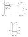
- FIG. 1Eis a side view of the same simple “trampoline-style” high capacity stacking output tray, showing a leg brace from the frame to the floor near the side of the document production machine for supporting the weight of relatively larger stacks of outputted sheets, and also showing a travel limiter to keep the stack support platform from moving too far down and over-extending the springs;
- FIG. 1Fis a side view of a simple “trampoline-style” high capacity stacking output tray with a large frame extending down to the floor on all sides of the stack, where part of the frame adjacent the document production machine also functions as a guide track to guide and stabilize the stack support platform as it moves downward, for supporting the weight of extremely large stacks of outputted sheets;
- FIG. 2shows an isometric view of an alternative simple “trampoline-style” high capacity stacking output tray with springs configured both to stack sheets vertically and to facilitate operator access for sheet removal;
- FIG. 3Ashows an isometric view of a wedge-shaped shim which can be positioned on the output tray to obtain either “uphill” or “downhill” stacking, depending on its orientation, or removed entirely to obtain flat stacking;
- FIG. 3Bshows uphill stacking accomplished by placing the low side of the shim toward the side of the output tray adjacent the copier and below the copier output port;
- FIG. 3Cshows downhill stacking accomplished by placing the high side of the shim toward the side of the output tray away from the copier and opposite the copier output port;
- FIG. 4shows a variable length stack edge alignment surface comprised of a wide belt which unrolls from the top of the output tray support frame in “windowshade” style to provide a smooth alignment surface which does not move relative to the stack;
- FIG. 5shows an alternative variable length stack edge alignment surface comprised of a wide belt which moves over a roller at the top of the output tray support frame, where one end of the belt is attached to the stack support platform and the other end of the belt is attached to a spring connected to the frame;
- FIG. 6shows an alternative simple, high capacity output tray where the biasing element is a telescoping cylinder that compresses as sheets are stacked on the stack support platform.
- the present inventionis not limited to the specific embodiments illustrated herein.
- the specific exemplary embodiments disclosedshow a high-capacity stacking output tray that moves vertically downward, with either a flat or an inclined stacking surface at a selected stacking angle to the horizontal.
- angle adjustment devicessuch as variable length braces or wedges attached to the frame, it is possible to obtain substantially non-vertical downward movement of the output tray while maintaining the output tray surface at substantially a right angle to the direction of movement, thereby optimizing the alignment and square stacking capacity of the system.
- FIG. 1shows a simple “trampoline-style” high capacity stacking output catch tray 100 with springs as biasing elements 120 connecting a frame 110 to a stack support platform 130 , wherein the springs 120 are configured to catch and accumulate a vertical stack of sheets or sets output by a document production machine such as a copier, printer, or fax machine.
- the frame 110defines a rectangular opening somewhat larger than the approximate size of the sheets to be caught and stacked.
- coupling devices known in the art as hooks 115used to couple the frame 110 to the copier.
- the springs 120connect the frame 110 to the stack support platform 130 , the proximal ends 121 of the springs 120 being coupled to the frame 110 and the distal ends 122 of the springs 120 being coupled to and about the perimeter of a rectangular stack support platform 130 of approximately the size of the sheets to be stacked.
- the stack support platform 130is thereby suspended from the frame 110 by means of the springs 120 and is free to move downward in an approximately vertical direction in response to the weight of an accumulating stack of sheets or sets output by the copier.
- the rectangular dimensions of the frame 110 and stack support platform 130may be varied, according to the dimensions of the sheets to be stacked, where relatively precise alignment of the stack edge is sought.
- a single large traymay suffice for all of the sizes of paper or documents which a particular copier is capable of producing.
- a traycan be dimensioned to closely fit the stack in one direction but be relatively looser in another, for instance to allow for lateral offsetting of sets or jobs.
- the frame 110may be constructed in such a manner as to allow the lengths of its sides to be adjusted in the field by an operator, so that a single output tray 100 can be configured to define a plurality of differently dimensioned rectangles, according to the precise dimensions of the sheets to be stacked and other factors such as offsetting. The same may be provided with respect to the stack support platform 130 .
- the springs 120are arranged so as to provide triangulation and lateral stability to the stack support platform 130 , although the springs 120 could be configured so as to hang straight down or in some other arrangement. Additionally, one or more dampening devices in the nature of shock absorbers may be provided to further reduce swaying and resonant motion of the stack in response to cyclic rhythms or movements induced by operation of the copier.
- the output tray 100When or before the output tray 100 reaches maximum capacity it is partially or completely emptied by an operator, reducing or eliminating the weight of the stack and allowing the springs 120 to reposition the stack support platform 130 upward to maintain either the unloaded stack support platform 130 or the top of the stack at an elevation within an acceptable range 170 relative to the elevation of the copier output port.
- one or more portions of the frame 110 on the side opposite the copier output portare higher than the output port to provide a backstop 111 , so that sheets ejected at an angle substantially upward of horizontal will not fly over the frame 110 but will instead strike the backstop 111 and be captured.
- coiled metallic springs 120numerous alternative energy-storing biasing elements may be provided such as springs of various configurations (coiled, leaf, torsion bar), elastic cords or bands made of rubber or elastomers, bungee cords, pressurized piston-cylinder devices, weights, and/or pulleys, alone or in combination with each other.
- the springs 120stretch in response to the weight of the stack accumulating on top of the stack support platform 130 , allowing the stack support platform 130 to move downward and accommodate a stack of increasing length while maintaining the elevation of the top of the accumulating stack within a desirable range 170 relative to the copier output port. Since the weight of the stack increases linearly with the length of the stack, springs are particularly well-suited for use as biasing elements because they can easily be fashioned to have an inherently linearly increasing spring rate which is directly proportionate to the vertical linear movement of the stack support platform 130 . Elastic cords or bands are specifically preferred for use as springs 120 because they can easily be fashioned with a relatively smooth exterior surface which is less likely than other types of springs to catch or bind the edges of sheets or stacks in the output tray 100 .
- the energy storing capacity of the springs 120provides assistance to an operator when lifting sheets and/or stacks to remove them from the output tray 100 .
- the springs 120stretch under the weight of the stack accumulating on top of the stack support platform 130 , the springs 120 simultaneously act as variable length alignment surfaces 140 to produce a substantially aligned, straight stack, without the need for an additional component to provide an alignment surface.
- there is some relative motion between the surface of the springs 120 as they stretch, and the edges of sheets or sets accumulating in the stacksuch relative motion is far less than would occur with an alignment surface which was fixed in relation to the movement of the stack support platform 130 as in prior art.
- the relatively smooth exterior surface of the preferred elastic cords or bands as springs 120further reduces friction, binding, lifting and creeping, thereby additionally facilitating the aligning and straightening action of the springs 120 .
- sufficient capacityis provided by the output tray 100 so that constant monitoring or attention by an operator will not be required, and an interval of at least several minutes will elapse between occasions when an operator must reduce or remove the stack of sheets and/or sets accumulated in the output tray 100 .
- one or more simple detectors and/or switches of types well known in the artcan be added to provide signals to the copier or an operator to warn when maximum capacity of the output tray 100 is being approached or has been reached, and additionally if desired to cause the copier to cease output until the stack in the output tray 100 is removed or at least reduced.
- variation in stack height capacity, weight capacity, and range of acceptable stack height relative to the copier output portare accommodated by various combinations of springs 120 of different lengths and effective spring rates, and/or by additional mounting points on the frame 110 and stack support platform 130 to accommodate different numbers, sizes and arrangements of springs 120 .
- further adjustabilitycan be added by various devices known in the art, such as screw adjusters which move the mounting points of the springs 120 to vary their tension or pre-load.
- the frame 110may be entirely supported by and suspended from the hooks 115 coupled to the copier, in combination with cantilevered forces against the side of the copier, friction and the moment of inertia generated by the weight of the output tray 100 and the stack it contains, as depicted in most of the figures.
- additional weight bearing capacity for large stacksis provided by at least one angled brace 112 in the nature of a knee brace, the upper end of which is attached to the frame 110 and the lower end of which rests against the side of the copier.
- FIG. 1Dadditional weight bearing capacity for large stacks is provided by at least one angled brace 112 in the nature of a knee brace, the upper end of which is attached to the frame 110 and the lower end of which rests against the side of the copier.
- increased additional weight bearing capacityis provided by a leg 113 , the upper end of which is attached to the frame 110 and the lower end of which rests upon a floor or other horizontal surface adjacent the copier.
- extreme weight bearing capacityis provided by enlarging the frame 110 so that its lower portion rests directly upon a floor or other horizontal surface adjacent the copier.
- an adjustable travel limiter 114may be provided to contact the underside of the stack support platform 130 and prevent further downward movement of the stack support platform 130 , as depicted in FIG. 1E and FIG. 1F .
- a guide track 116may be provided to guide and stabilize the stack platform 130 as it moves downward under the weight of an extremely large stack.
- the guide track 116is an integral part of a large frame 110 , thereby minimizing complexity and number of parts.
- the guide track 116may be a detachable component available as an upgrade for frames 110 of various sizes.
- the hooks 115can be fashioned in various ways to provide maximum compatibility with different sizes, types, models and brands of copiers. Such ways include interchangeable frames with integral hooks of a desired configuration, or frames with detachable hooks which can be changed according to the configuration required for coupling to a particular copier.
- FIG. 2a preferred embodiment is shown of the frame 110 and springs 120 defining a lengthwise opening in one side of the output tray 100 to facilitate operator access for removal of sheets and/or sets from the output tray 100 .
- the access opening shown in FIG. 2is on the side of frame 110 opposite the sheet output port, but may be configured to be on any of the three sides not adjacent the copier.
- a simple wedge-shaped stack support platform angle adjusting shim 131is shown.
- the shim 131is rectangular.
- the shim 131fits through the frame 110 and rests on top of the stack support platform 130 , and is otherwise dimensioned to be compatible with the size of sheets and/or sets to be accumulated in the output tray 100 .
- one side of the shim 131is substantially higher than the other so that when the shim 131 is placed on top of the stack support platform 130 , either uphill or downhill stacking can be provided according to the orientation of the shim 131 .
- the shim 131is not employed and sheets or sets output by the copier rest directly on top of the stack support platform 130 .
- uphill stackingis accomplished by placing the low side of the shim 131 towards the side of the output tray 100 adjacent the copier and below the copier output port.
- Downhill stackingis accomplished by reversing the orientation of the shim 131 so that the high side is below the output port and adjacent the copier, as shown in FIG. 3C .
- the shim 131can be maintained in position by mechanical interlock with the springs 120 and their mounting points on the stack support platform 130 , the weight of the stack resting on the shim 131 , other fastening means commonly known in the art such as velcro, single- or double-sided tape, glue, screws, clips, etc., or various combinations thereof.
- FIG. 4shows a side view of a variable length stack edge alignment surface 140 comprised of a belt-like flexible sheet or membrane which unrolls from the top of the output tray support frame 110 in “windowshade” style to provide a smooth alignment surface which does not move relative to the stack.
- a single stack edge alignment surface 140is utilized, being approximately the width of the side of the frame 110 from which it unrolls, but in alternative embodiments two or more “belts” of narrower width may be employed.
- the material of the variable length stack alignment surface 140is flexible enough to be rolled or curved, the number and arrangement of the springs 120 provide sufficient lateral and longitudinal support so that the material is not deformed beyond a range acceptable for a desired stack edge alignment tolerance.
- a single roll of such material for a variable length stack edge alignment surface 140may be provided, on the side of the frame 110 adjacent the copier.
- the roll of flexible material for the stack edge alignment surface 140is positioned sufficiently below the copier output port so as not to interfere with ejected sheets and/or sets, but not so low as to allow sheets and/or sets at the top of the stack to slide out of the output tray 100 .
- the rollmay be located on any one side of the frame 110 , or an additional roll or rolls may be located on any two or three or on all four sides of the frame 110 .
- the length of the stack edge alignment surface 140is determined according to the maximum desired stack height or output capacity of the output tray 100 , and will vary according to particular applications.
- variable length stack edge alignment surface 140is attached to and wrapped around a roller 141 located adjacent a top edge of the frame 110 , and the other end is attached to the stack support platform 130 .
- the “windowshade” style variable length stack edge alignment surface 140unrolls and re-rolls onto the roller 141 according to the upward and downward movement of the stack support platform 130 responsive to the height and weight of the stack in the output tray 100 .
- the spring 120may be separate from a roller rewind spring 142 provided keep the variable length stack edge alignment surface 140 taught and to cause it to roll back around the roller 141 when the stack support platform 130 rises after being unloaded.
- the functionality of some of the springs 120could be incorporated into a roller rewind spring 142 and some of the springs 120 eliminated.
- FIG. 5shows an alternative variable length stack edge alignment surface 140 that moves over a roller 141 located adjacent a top edge of the frame 110 , where one end of the variable length stack edge alignment surface 140 is attached to the stack support platform 130 and the other end is attached to a spring 120 , which in turn is attached to the frame 110 .
- FIG. 6shows an alternative simple, high capacity output tray 100 where the biasing element is a telescoping cylinder 124 that compresses as sheets are stacked on the stack support platform 130 .
- the top of upper end of the cylinder 124contacts the underside of the stack support platform 130 , while the lower end of the cylinder 124 rests on the floor.
- the cylinder 124is sealed and capable of being pressurized either in the manner of a sealed “air spring” or hydraulically with the addition of a reservoir and pump.
- the cylinder 124may be pre-pressurized or “pre-loaded” if desired, so that it will not begin to compress until a desired minimum stack weight is reached. Alternatively, the cylinder 124 may be essentially un-pressurized until compressed as sheets accumulate on the stack support platform 130 .
- the inventionhas general applicability to various fields of use relating to document production machines.
- the inventionmay be used for printers, whether stand-alone or networked, fax machines, or any other type of device which outputs sheets or sets of sheets of relatively thin, flexible material.
Landscapes
- Engineering & Computer Science (AREA)
- Mechanical Engineering (AREA)
- Pile Receivers (AREA)
Abstract
Description
Claims (9)
Priority Applications (1)
| Application Number | Priority Date | Filing Date | Title |
|---|---|---|---|
| US12/115,480US7552923B2 (en) | 2000-09-14 | 2008-05-05 | Simple and inexpensive high capacity output catch tray for document production machines |
Applications Claiming Priority (5)
| Application Number | Priority Date | Filing Date | Title |
|---|---|---|---|
| US09/661,968US6572293B1 (en) | 2000-09-14 | 2000-09-14 | Simple and inexpensive high-capacity output catch tray for document production machines |
| US10/404,942US6832865B2 (en) | 2000-09-14 | 2003-03-31 | Simple and inexpensive high-capacity output catch tray for document production machines |
| US10/983,431US7204484B2 (en) | 2000-09-14 | 2004-11-08 | Simple and inexpensive high-capacity output catch tray for document production machines |
| US11/557,762US7367559B2 (en) | 2000-09-14 | 2006-11-08 | Simple and inexpensive high-capacity output catch tray for document production machines |
| US12/115,480US7552923B2 (en) | 2000-09-14 | 2008-05-05 | Simple and inexpensive high capacity output catch tray for document production machines |
Related Parent Applications (1)
| Application Number | Title | Priority Date | Filing Date |
|---|---|---|---|
| US11/557,762ContinuationUS7367559B2 (en) | 2000-09-14 | 2006-11-08 | Simple and inexpensive high-capacity output catch tray for document production machines |
Publications (2)
| Publication Number | Publication Date |
|---|---|
| US20080211170A1 US20080211170A1 (en) | 2008-09-04 |
| US7552923B2true US7552923B2 (en) | 2009-06-30 |
Family
ID=24655835
Family Applications (5)
| Application Number | Title | Priority Date | Filing Date |
|---|---|---|---|
| US09/661,968Expired - LifetimeUS6572293B1 (en) | 2000-09-14 | 2000-09-14 | Simple and inexpensive high-capacity output catch tray for document production machines |
| US10/404,942Expired - LifetimeUS6832865B2 (en) | 2000-09-14 | 2003-03-31 | Simple and inexpensive high-capacity output catch tray for document production machines |
| US10/983,431Expired - LifetimeUS7204484B2 (en) | 2000-09-14 | 2004-11-08 | Simple and inexpensive high-capacity output catch tray for document production machines |
| US11/557,762Expired - LifetimeUS7367559B2 (en) | 2000-09-14 | 2006-11-08 | Simple and inexpensive high-capacity output catch tray for document production machines |
| US12/115,480Expired - LifetimeUS7552923B2 (en) | 2000-09-14 | 2008-05-05 | Simple and inexpensive high capacity output catch tray for document production machines |
Family Applications Before (4)
| Application Number | Title | Priority Date | Filing Date |
|---|---|---|---|
| US09/661,968Expired - LifetimeUS6572293B1 (en) | 2000-09-14 | 2000-09-14 | Simple and inexpensive high-capacity output catch tray for document production machines |
| US10/404,942Expired - LifetimeUS6832865B2 (en) | 2000-09-14 | 2003-03-31 | Simple and inexpensive high-capacity output catch tray for document production machines |
| US10/983,431Expired - LifetimeUS7204484B2 (en) | 2000-09-14 | 2004-11-08 | Simple and inexpensive high-capacity output catch tray for document production machines |
| US11/557,762Expired - LifetimeUS7367559B2 (en) | 2000-09-14 | 2006-11-08 | Simple and inexpensive high-capacity output catch tray for document production machines |
Country Status (5)
| Country | Link |
|---|---|
| US (5) | US6572293B1 (en) |
| EP (1) | EP1324938B1 (en) |
| AU (2) | AU2001287069B2 (en) |
| DE (1) | DE60115488T2 (en) |
| WO (1) | WO2002022481A2 (en) |
Cited By (1)
| Publication number | Priority date | Publication date | Assignee | Title |
|---|---|---|---|---|
| US20080000393A1 (en)* | 2003-11-20 | 2008-01-03 | Pacific Bin Corporation | Self-adjusting goods display system and method |
Families Citing this family (17)
| Publication number | Priority date | Publication date | Assignee | Title |
|---|---|---|---|---|
| US6572293B1 (en)* | 2000-09-14 | 2003-06-03 | Electronics For Imaging, Inc. | Simple and inexpensive high-capacity output catch tray for document production machines |
| US6934506B1 (en)* | 2004-05-27 | 2005-08-23 | Robert S. Collaco | Accessory for recycling paper |
| EP1977298B1 (en)* | 2006-01-12 | 2011-10-26 | The Gorman-Rupp Company | Air release valve |
| US20080055089A1 (en)* | 2006-08-30 | 2008-03-06 | Intermec Ip Corp. | Adhesive thermo printable label with RFID flap antenna for metallic surfaces |
| TWI321122B (en)* | 2006-12-15 | 2010-03-01 | Lite On Technology Corp | Paper-feeding mechanism capable of adjusting skew print medium |
| SI22566A (en)* | 2007-06-21 | 2008-12-31 | Vinko Kunc | Insulated interface with a capacitance barrier including a differentiating circuit and signal transmission procedure by way of such an insulated interface |
| US7631864B1 (en) | 2008-12-17 | 2009-12-15 | Xerox Corporation | Catch tray for document production device |
| US9821944B1 (en)* | 2013-06-17 | 2017-11-21 | Amazon Technologies, Inc. | Package deceleration and protection systems |
| JP7072343B2 (en)* | 2015-10-16 | 2022-05-20 | セイコーエプソン株式会社 | Media ejector and image reader |
| CN105236193A (en)* | 2015-10-18 | 2016-01-13 | 常州纳捷机电科技有限公司 | Paper slot of plotting instrument |
| US9968189B2 (en) | 2015-12-04 | 2018-05-15 | Penco Products, Inc. | Storage system employing removable, automatically adjustable platform and removable, automatically adjustable platform employable with said storage system |
| JP2019531844A (en) | 2016-08-08 | 2019-11-07 | ロイス ニューカムRoyce NEWCOMB | Secure package delivery and collection system |
| US12016478B2 (en) | 2016-08-08 | 2024-06-25 | Royce Newcomb | Secure package delivery and pick-up system |
| WO2019226176A1 (en)* | 2018-05-25 | 2019-11-28 | Hewlett-Packard Development Company, L.P. | Media catchers |
| WO2021091568A1 (en)* | 2019-11-08 | 2021-05-14 | Hewlett-Packard Development Company, L.P. | Output tray |
| US10758763B1 (en)* | 2019-05-21 | 2020-09-01 | Samuel Chen | Accessory structure trampoline |
| JP2024160790A (en)* | 2023-05-02 | 2024-11-15 | 株式会社リコー | Seat storage device |
Citations (49)
| Publication number | Priority date | Publication date | Assignee | Title |
|---|---|---|---|---|
| US1694638A (en)* | 1927-05-28 | 1928-12-11 | John Toman | Attachment for printing presses |
| US1928923A (en)* | 1930-08-20 | 1933-10-03 | Goss Printing Press Co Ltd | Delivery mechanism for printing presses |
| GB494101A (en) | 1937-04-19 | 1938-10-19 | British Tabulating Mach Co Ltd | Improvements in or relating to mechanism for stacking cards or sheets |
| US3046010A (en)* | 1960-02-04 | 1962-07-24 | Eureka Specialty Printing Co | Stacker apparatus |
| US3137499A (en)* | 1962-11-20 | 1964-06-16 | Burroughs Corp | Document stacking device |
| US3149836A (en)* | 1962-04-25 | 1964-09-22 | Sperry Rand Corp | Unloadable document stacking mechanism |
| US3655186A (en)* | 1970-12-14 | 1972-04-11 | Ardac Inc | Stacker for paper currency |
| US3889824A (en)* | 1972-11-28 | 1975-06-17 | Masson Scott Thrissell Eng Ltd | Apparatus for ejecting stacks of articles from containers |
| US3907281A (en)* | 1974-03-15 | 1975-09-23 | George R Hall Inc | Paper catcher device |
| US4310160A (en)* | 1979-09-10 | 1982-01-12 | Leo Willette | Card shuffling device |
| US4329046A (en)* | 1979-10-30 | 1982-05-11 | Xerox Corporation | Method for operating a reproduction machine with unlimited catch tray for multimode operation |
| US4357127A (en)* | 1978-10-17 | 1982-11-02 | Avedko, B.V. | Apparatus for the stacking of objects |
| US4624452A (en)* | 1985-08-19 | 1986-11-25 | Pulskamp Nicholas R | Board inserter for printing press |
| US4667953A (en)* | 1985-08-28 | 1987-05-26 | Mitsubishi Jukogyo Kabushiki Kaisha | Sheet stacker |
| US4718657A (en)* | 1983-12-01 | 1988-01-12 | Delphax Systems | Paper stacker |
| US4946152A (en)* | 1987-09-04 | 1990-08-07 | Minolta Camera Kabushiki Kaisha | Sorter-finisher |
| US4980780A (en)* | 1988-08-29 | 1990-12-25 | Ricoh Company, Ltd. | Image forming system |
| US4989853A (en)* | 1988-11-28 | 1991-02-05 | Xerox Corporation | Apparatus for offsetting sheets |
| US4990967A (en)* | 1989-08-21 | 1991-02-05 | International Business Machines Corporation | Copying method and apparatus |
| US5048983A (en) | 1989-05-26 | 1991-09-17 | Kentek Information Systems, Inc. | Electrographic typewriter |
| DE4020730A1 (en) | 1990-06-29 | 1992-01-09 | Krause Biagosch Gmbh | Mechanical re-stacking for sheets of paper - removes each topmost sheet from delivery unit before forming new stack |
| US5126786A (en) | 1988-10-29 | 1992-06-30 | Ricoh Company, Ltd. | Image forming system |
| US5253757A (en) | 1992-05-12 | 1993-10-19 | Ball State University | Drawing receptacle for use with computer printers |
| US5273274A (en) | 1992-09-04 | 1993-12-28 | Xerox Corporation | Sheet feeding system with lateral registration and method for registering sheets |
| US5284336A (en) | 1992-08-28 | 1994-02-08 | Bell & Howell Phillipsburg Company | Slidable, lowerable, and removable bin tray |
| US5305996A (en) | 1991-11-13 | 1994-04-26 | Fujitsu Limited | Paper hopper |
| US5318401A (en) | 1992-05-26 | 1994-06-07 | Xerox Corporation | Stacking tray system with nonvertically receding elevator yielding square stacks |
| US5332210A (en) | 1992-11-18 | 1994-07-26 | Pitney Bowes Inc. | Variable size envelope drop stacker having means for assuring envelope sealing |
| US5346203A (en) | 1993-08-30 | 1994-09-13 | Xerox Corporation | High capacity sheet stacking system with variable height input and stacking registration |
| US5431530A (en) | 1992-03-13 | 1995-07-11 | Matsushita Electric Industrial Co., Ltd. | Apparatus for transferring and stocking lead plates for storage batteries |
| US5547178A (en) | 1995-02-23 | 1996-08-20 | Xerox Corporation | Printer mailbox split jobs overflow banner sheet indicator system |
| US5551686A (en) | 1995-02-23 | 1996-09-03 | Xerox Corporation | Printing and mailbox system for shared users with bins almost full sensing |
| US5594536A (en) | 1994-12-16 | 1997-01-14 | Fuji Xerox Co., Ltd. | Reliable transfer film attachment structure |
| US5599009A (en) | 1995-10-05 | 1997-02-04 | Xerox Corporation | Stacking height estimation correction system |
| US5603492A (en) | 1996-01-11 | 1997-02-18 | Xerox Corporation | Sheet stacking bin fullness control system |
| US5609333A (en) | 1995-10-05 | 1997-03-11 | Xerox Corporation | Sheet stack height control system |
| EP0768266A1 (en) | 1995-10-05 | 1997-04-16 | Xerox Corporation | Sheet stacking bin fullness control system |
| US5628042A (en) | 1994-01-20 | 1997-05-06 | Xerox Corporation | Solenoid controlled sheet registration mechanism |
| US5697761A (en) | 1996-01-11 | 1997-12-16 | Xerox Corporation | Mailbox bin job set extractor |
| US5704609A (en) | 1995-12-07 | 1998-01-06 | Xerox Corporation | Integrated inter-mailbox modules bypass transport and purge tray system |
| US5823529A (en) | 1995-10-05 | 1998-10-20 | Xerox Corporation | Single stack height sensor for plural sheet stacking bins system |
| US5832358A (en) | 1997-09-02 | 1998-11-03 | Xerox Corporation | Unscheduled set ejection method in a finisher |
| US5884123A (en) | 1997-11-14 | 1999-03-16 | Xerox Corporation | Compact reproduction machine having separately framed mutually aligning modules |
| US5924808A (en) | 1998-06-29 | 1999-07-20 | Sides, Ii; William R. | Paper catching tray for electronic printers and other devices |
| DE19907444A1 (en) | 1998-03-23 | 1999-09-30 | Heidelberger Druckmasch Ag | Appliance for lifting and lowering stacked sheets in sheet-processing machine |
| US6000770A (en) | 1999-01-15 | 1999-12-14 | Frich; Mark R. | Library book bin with a vertically adjustable floor |
| US6035973A (en) | 1995-03-09 | 2000-03-14 | Ergonomics Specialists | Device for and method of vertically adjusting parts in a bin |
| US6206365B1 (en) | 1997-11-14 | 2001-03-27 | Sharp Kabushiki Kaisha | Sheet receiving apparatus for sorting and stacking sheets on a tray with friction-free horizontal reciprocation |
| US6572293B1 (en)* | 2000-09-14 | 2003-06-03 | Electronics For Imaging, Inc. | Simple and inexpensive high-capacity output catch tray for document production machines |
Family Cites Families (5)
| Publication number | Priority date | Publication date | Assignee | Title |
|---|---|---|---|---|
| US1894638A (en)* | 1930-03-18 | 1933-01-17 | American Thermos Bottle Co | Method of regulating the cooling effect of a refrigerant |
| US4310180A (en)* | 1977-05-18 | 1982-01-12 | Burroughs Corporation | Protected document and method of making same |
| US5828670A (en)* | 1995-06-06 | 1998-10-27 | Symmetricom, Inc. | Distribution of synchronization in a synchronous optical environment |
| US6470032B2 (en)* | 2001-03-20 | 2002-10-22 | Alloptic, Inc. | System and method for synchronizing telecom-related clocks in ethernet-based passive optical access network |
| EP1595349B1 (en)* | 2003-02-20 | 2008-10-29 | Zarlink Semiconductor Inc. | Alignment of clocks over multiple packet networks |
- 2000
- 2000-09-14USUS09/661,968patent/US6572293B1/ennot_activeExpired - Lifetime
- 2001
- 2001-09-04AUAU2001287069Apatent/AU2001287069B2/ennot_activeCeased
- 2001-09-04AUAU8706901Apatent/AU8706901A/enactivePending
- 2001-09-04WOPCT/US2001/027463patent/WO2002022481A2/enactiveIP Right Grant
- 2001-09-04EPEP01966566Apatent/EP1324938B1/ennot_activeExpired - Lifetime
- 2001-09-04DEDE60115488Tpatent/DE60115488T2/ennot_activeExpired - Fee Related
- 2003
- 2003-03-31USUS10/404,942patent/US6832865B2/ennot_activeExpired - Lifetime
- 2004
- 2004-11-08USUS10/983,431patent/US7204484B2/ennot_activeExpired - Lifetime
- 2006
- 2006-11-08USUS11/557,762patent/US7367559B2/ennot_activeExpired - Lifetime
- 2008
- 2008-05-05USUS12/115,480patent/US7552923B2/ennot_activeExpired - Lifetime
Patent Citations (53)
| Publication number | Priority date | Publication date | Assignee | Title |
|---|---|---|---|---|
| US1694638A (en)* | 1927-05-28 | 1928-12-11 | John Toman | Attachment for printing presses |
| US1928923A (en)* | 1930-08-20 | 1933-10-03 | Goss Printing Press Co Ltd | Delivery mechanism for printing presses |
| GB494101A (en) | 1937-04-19 | 1938-10-19 | British Tabulating Mach Co Ltd | Improvements in or relating to mechanism for stacking cards or sheets |
| US3046010A (en)* | 1960-02-04 | 1962-07-24 | Eureka Specialty Printing Co | Stacker apparatus |
| US3149836A (en)* | 1962-04-25 | 1964-09-22 | Sperry Rand Corp | Unloadable document stacking mechanism |
| US3137499A (en)* | 1962-11-20 | 1964-06-16 | Burroughs Corp | Document stacking device |
| US3655186A (en)* | 1970-12-14 | 1972-04-11 | Ardac Inc | Stacker for paper currency |
| US3889824A (en)* | 1972-11-28 | 1975-06-17 | Masson Scott Thrissell Eng Ltd | Apparatus for ejecting stacks of articles from containers |
| US3907281A (en)* | 1974-03-15 | 1975-09-23 | George R Hall Inc | Paper catcher device |
| US4357127A (en)* | 1978-10-17 | 1982-11-02 | Avedko, B.V. | Apparatus for the stacking of objects |
| US4310160A (en)* | 1979-09-10 | 1982-01-12 | Leo Willette | Card shuffling device |
| US4329046A (en)* | 1979-10-30 | 1982-05-11 | Xerox Corporation | Method for operating a reproduction machine with unlimited catch tray for multimode operation |
| US4718657A (en)* | 1983-12-01 | 1988-01-12 | Delphax Systems | Paper stacker |
| US4624452A (en)* | 1985-08-19 | 1986-11-25 | Pulskamp Nicholas R | Board inserter for printing press |
| US4667953A (en)* | 1985-08-28 | 1987-05-26 | Mitsubishi Jukogyo Kabushiki Kaisha | Sheet stacker |
| US4946152A (en)* | 1987-09-04 | 1990-08-07 | Minolta Camera Kabushiki Kaisha | Sorter-finisher |
| US4980780A (en)* | 1988-08-29 | 1990-12-25 | Ricoh Company, Ltd. | Image forming system |
| US5126786A (en) | 1988-10-29 | 1992-06-30 | Ricoh Company, Ltd. | Image forming system |
| US4989853A (en)* | 1988-11-28 | 1991-02-05 | Xerox Corporation | Apparatus for offsetting sheets |
| US5048983A (en) | 1989-05-26 | 1991-09-17 | Kentek Information Systems, Inc. | Electrographic typewriter |
| US4990967A (en)* | 1989-08-21 | 1991-02-05 | International Business Machines Corporation | Copying method and apparatus |
| DE4020730A1 (en) | 1990-06-29 | 1992-01-09 | Krause Biagosch Gmbh | Mechanical re-stacking for sheets of paper - removes each topmost sheet from delivery unit before forming new stack |
| US5305996A (en) | 1991-11-13 | 1994-04-26 | Fujitsu Limited | Paper hopper |
| US5431530A (en) | 1992-03-13 | 1995-07-11 | Matsushita Electric Industrial Co., Ltd. | Apparatus for transferring and stocking lead plates for storage batteries |
| US5253757A (en) | 1992-05-12 | 1993-10-19 | Ball State University | Drawing receptacle for use with computer printers |
| US5318401A (en) | 1992-05-26 | 1994-06-07 | Xerox Corporation | Stacking tray system with nonvertically receding elevator yielding square stacks |
| US5284336A (en) | 1992-08-28 | 1994-02-08 | Bell & Howell Phillipsburg Company | Slidable, lowerable, and removable bin tray |
| US5273274A (en) | 1992-09-04 | 1993-12-28 | Xerox Corporation | Sheet feeding system with lateral registration and method for registering sheets |
| US5332210A (en) | 1992-11-18 | 1994-07-26 | Pitney Bowes Inc. | Variable size envelope drop stacker having means for assuring envelope sealing |
| US5346203A (en) | 1993-08-30 | 1994-09-13 | Xerox Corporation | High capacity sheet stacking system with variable height input and stacking registration |
| US5628042A (en) | 1994-01-20 | 1997-05-06 | Xerox Corporation | Solenoid controlled sheet registration mechanism |
| US5594536A (en) | 1994-12-16 | 1997-01-14 | Fuji Xerox Co., Ltd. | Reliable transfer film attachment structure |
| US5551686A (en) | 1995-02-23 | 1996-09-03 | Xerox Corporation | Printing and mailbox system for shared users with bins almost full sensing |
| US5547178A (en) | 1995-02-23 | 1996-08-20 | Xerox Corporation | Printer mailbox split jobs overflow banner sheet indicator system |
| US6035973A (en) | 1995-03-09 | 2000-03-14 | Ergonomics Specialists | Device for and method of vertically adjusting parts in a bin |
| EP0768264A1 (en) | 1995-10-05 | 1997-04-16 | Xerox Corporation | Stacking height estimation correction system |
| US5599009A (en) | 1995-10-05 | 1997-02-04 | Xerox Corporation | Stacking height estimation correction system |
| US5609333A (en) | 1995-10-05 | 1997-03-11 | Xerox Corporation | Sheet stack height control system |
| US5823529A (en) | 1995-10-05 | 1998-10-20 | Xerox Corporation | Single stack height sensor for plural sheet stacking bins system |
| EP0768266A1 (en) | 1995-10-05 | 1997-04-16 | Xerox Corporation | Sheet stacking bin fullness control system |
| US5704609A (en) | 1995-12-07 | 1998-01-06 | Xerox Corporation | Integrated inter-mailbox modules bypass transport and purge tray system |
| US5603492A (en) | 1996-01-11 | 1997-02-18 | Xerox Corporation | Sheet stacking bin fullness control system |
| US5697761A (en) | 1996-01-11 | 1997-12-16 | Xerox Corporation | Mailbox bin job set extractor |
| US5832358A (en) | 1997-09-02 | 1998-11-03 | Xerox Corporation | Unscheduled set ejection method in a finisher |
| US6206365B1 (en) | 1997-11-14 | 2001-03-27 | Sharp Kabushiki Kaisha | Sheet receiving apparatus for sorting and stacking sheets on a tray with friction-free horizontal reciprocation |
| US5884123A (en) | 1997-11-14 | 1999-03-16 | Xerox Corporation | Compact reproduction machine having separately framed mutually aligning modules |
| DE19907444A1 (en) | 1998-03-23 | 1999-09-30 | Heidelberger Druckmasch Ag | Appliance for lifting and lowering stacked sheets in sheet-processing machine |
| US5924808A (en) | 1998-06-29 | 1999-07-20 | Sides, Ii; William R. | Paper catching tray for electronic printers and other devices |
| US6000770A (en) | 1999-01-15 | 1999-12-14 | Frich; Mark R. | Library book bin with a vertically adjustable floor |
| US6572293B1 (en)* | 2000-09-14 | 2003-06-03 | Electronics For Imaging, Inc. | Simple and inexpensive high-capacity output catch tray for document production machines |
| US6832865B2 (en)* | 2000-09-14 | 2004-12-21 | Electronics For Imaging, Inc. | Simple and inexpensive high-capacity output catch tray for document production machines |
| US7204484B2 (en)* | 2000-09-14 | 2007-04-17 | Electronics For Imaging, Inc. | Simple and inexpensive high-capacity output catch tray for document production machines |
| US7367559B2 (en)* | 2000-09-14 | 2008-05-06 | Electronics For Imaging, Inc. | Simple and inexpensive high-capacity output catch tray for document production machines |
Non-Patent Citations (1)
| Title |
|---|
| Mazzarelli, et al.; "Paper Stacker"; Aug. 1, 1980; IBM Technical Disclosure Bulletin, p. 1125, vol. 23, No. 3. |
Cited By (1)
| Publication number | Priority date | Publication date | Assignee | Title |
|---|---|---|---|---|
| US20080000393A1 (en)* | 2003-11-20 | 2008-01-03 | Pacific Bin Corporation | Self-adjusting goods display system and method |
Also Published As
| Publication number | Publication date |
|---|---|
| US6572293B1 (en) | 2003-06-03 |
| US7204484B2 (en) | 2007-04-17 |
| WO2002022481A3 (en) | 2002-05-10 |
| US6832865B2 (en) | 2004-12-21 |
| US7367559B2 (en) | 2008-05-06 |
| US20030185614A1 (en) | 2003-10-02 |
| DE60115488D1 (en) | 2006-01-05 |
| AU2001287069B2 (en) | 2005-06-02 |
| WO2002022481A2 (en) | 2002-03-21 |
| AU8706901A (en) | 2002-03-26 |
| US20050062221A1 (en) | 2005-03-24 |
| US20080211170A1 (en) | 2008-09-04 |
| EP1324938A2 (en) | 2003-07-09 |
| DE60115488T2 (en) | 2006-07-27 |
| EP1324938B1 (en) | 2005-11-30 |
| US20070085264A1 (en) | 2007-04-19 |
Similar Documents
| Publication | Publication Date | Title |
|---|---|---|
| US7552923B2 (en) | Simple and inexpensive high capacity output catch tray for document production machines | |
| AU2001287069A1 (en) | High-Capacity output catch tray for document production machines | |
| US5346203A (en) | High capacity sheet stacking system with variable height input and stacking registration | |
| US5318401A (en) | Stacking tray system with nonvertically receding elevator yielding square stacks | |
| CA1240717A (en) | Paper stacker | |
| JP3043401B2 (en) | Document output device having device for preventing disorder | |
| DE69203484T2 (en) | Unit, provided with an alignment edge, to suppress the sheet compression when stacking. | |
| US5443249A (en) | In-bin stapling system with interactive registration wall | |
| DE69203485T2 (en) | Sheet guide plate with automatically maintained distance to the sheet stack. | |
| US6378864B1 (en) | Stacker | |
| US6209865B1 (en) | Method and apparatus for improved stacking quality in a device that effects one or more of media to an output storage location | |
| CA2076784C (en) | Sheet stacking apparatus | |
| US5152515A (en) | Variable trajectory document restacking system | |
| JPH0422826B2 (en) | ||
| US5921406A (en) | Passive paper stacker | |
| JP3561082B2 (en) | Sheet distribution device with stapler | |
| CN101284612B (en) | Paper loading machine, paper folding device and paper clearing system | |
| JPH03152058A (en) | Paper post-processing device | |
| JP3371117B2 (en) | Paper ejection processing device | |
| JPH0867407A (en) | Paper aligning device | |
| JP2020152524A (en) | Sheet stacking device and image forming device | |
| JPH061521A (en) | Sheet material post-processing equipment | |
| JPH0834557A (en) | Paper ejection device | |
| JPH03193395A (en) | paper handling device | |
| JPH09301615A (en) | Sheet distribution device |
Legal Events
| Date | Code | Title | Description |
|---|---|---|---|
| STCF | Information on status: patent grant | Free format text:PATENTED CASE | |
| REMI | Maintenance fee reminder mailed | ||
| FPAY | Fee payment | Year of fee payment:4 | |
| SULP | Surcharge for late payment | ||
| FPAY | Fee payment | Year of fee payment:8 | |
| AS | Assignment | Owner name:CITIBANK, N.A., AS ADMINISTRATIVE AGENT, TEXAS Free format text:GRANT OF SECURITY INTEREST IN PATENTS;ASSIGNOR:ELECTRONICS FOR IMAGING, INC.;REEL/FRAME:048002/0135 Effective date:20190102 | |
| AS | Assignment | Owner name:ROYAL BANK OF CANADA, CANADA Free format text:SECURITY INTEREST;ASSIGNOR:ELECTRONICS FOR IMAGING, INC.;REEL/FRAME:049840/0799 Effective date:20190723 Owner name:ELECTRONICS FOR IMAGING, INC., CALIFORNIA Free format text:RELEASE OF SECURITY INTEREST IN PATENTS;ASSIGNOR:CITIBANK, N.A., AS ADMINISTRATIVE AGENT;REEL/FRAME:049840/0316 Effective date:20190723 Owner name:DEUTSCHE BANK TRUST COMPANY AMERICAS, NEW YORK Free format text:SECOND LIEN SECURITY INTEREST IN PATENT RIGHTS;ASSIGNOR:ELECTRONICS FOR IMAGING, INC.;REEL/FRAME:049841/0115 Effective date:20190723 | |
| MAFP | Maintenance fee payment | Free format text:PAYMENT OF MAINTENANCE FEE, 12TH YEAR, LARGE ENTITY (ORIGINAL EVENT CODE: M1553); ENTITY STATUS OF PATENT OWNER: LARGE ENTITY Year of fee payment:12 | |
| AS | Assignment | Owner name:FIERY, LLC, CALIFORNIA Free format text:ASSIGNMENT OF ASSIGNORS INTEREST;ASSIGNOR:ELECTRONICS FOR IMAGING, INC.;REEL/FRAME:061132/0471 Effective date:20211230 | |
| AS | Assignment | Owner name:ELECTRONICS FOR IMAGING, INC., NEW HAMPSHIRE Free format text:RELEASE BY SECURED PARTY;ASSIGNOR:DEUTSCHE BANK TRUST COMPANY AMERICAS, AS AGENT;REEL/FRAME:066793/0001 Effective date:20240307 | |
| AS | Assignment | Owner name:CERBERUS BUSINESS FINANCE AGENCY, LLC, NEW YORK Free format text:SECURITY INTEREST;ASSIGNORS:ELECTRONICS FOR IMAGING, INC.;FIERY, LLC;REEL/FRAME:066794/0315 Effective date:20240312 | |
| AS | Assignment | Owner name:ROYAL BANK OF CANADA, CANADA Free format text:SECURITY INTEREST;ASSIGNOR:FIERY, LLC;REEL/FRAME:066797/0464 Effective date:20240314 | |
| AS | Assignment | Owner name:FIERY, LLC, CALIFORNIA Free format text:RELEASE OF PATENT SECURITY INTEREST;ASSIGNOR:CERBERUS BUSINESS FINANCE AGENCY, LLC;REEL/FRAME:069477/0479 Effective date:20241202 Owner name:ELECTRONICS FOR IMAGING, INC., CALIFORNIA Free format text:RELEASE OF PATENT SECURITY INTEREST;ASSIGNOR:CERBERUS BUSINESS FINANCE AGENCY, LLC;REEL/FRAME:069477/0479 Effective date:20241202 | |
| AS | Assignment | Owner name:FIERY, LLC, CALIFORNIA Free format text:RELEASE BY SECURED PARTY;ASSIGNOR:ROYAL BANK OF CANADA, AS COLLATERAL AGENT;REEL/FRAME:069546/0649 Effective date:20241202 | |
| AS | Assignment | Owner name:GLAS USA LLC (SUCCESSOR COLLATERAL AGENT), NEW JERSEY Free format text:ASSIGNMENT OF SECURITY INTEREST IN PATENTS;ASSIGNOR:ROYAL BANK OF CANADA (RESIGNING COLLATERAL AGENT);REEL/FRAME:070097/0810 Effective date:20250131 |