US7552506B2 - Filter assembly for vacuum cleaner - Google Patents
Filter assembly for vacuum cleanerDownload PDFInfo
- Publication number
- US7552506B2 US7552506B2US10/788,296US78829604AUS7552506B2US 7552506 B2US7552506 B2US 7552506B2US 78829604 AUS78829604 AUS 78829604AUS 7552506 B2US7552506 B2US 7552506B2
- Authority
- US
- United States
- Prior art keywords
- filter
- air
- case
- primary
- assembly
- Prior art date
- Legal status (The legal status is an assumption and is not a legal conclusion. Google has not performed a legal analysis and makes no representation as to the accuracy of the status listed.)
- Expired - Fee Related, expires
Links
Images


Classifications
- A—HUMAN NECESSITIES
- A47—FURNITURE; DOMESTIC ARTICLES OR APPLIANCES; COFFEE MILLS; SPICE MILLS; SUCTION CLEANERS IN GENERAL
- A47L—DOMESTIC WASHING OR CLEANING; SUCTION CLEANERS IN GENERAL
- A47L9/00—Details or accessories of suction cleaners, e.g. mechanical means for controlling the suction or for effecting pulsating action; Storing devices specially adapted to suction cleaners or parts thereof; Carrying-vehicles specially adapted for suction cleaners
- A47L9/10—Filters; Dust separators; Dust removal; Automatic exchange of filters
- A47L9/12—Dry filters
- A47L9/127—Dry filters tube- or sleeve-shaped
- A—HUMAN NECESSITIES
- A47—FURNITURE; DOMESTIC ARTICLES OR APPLIANCES; COFFEE MILLS; SPICE MILLS; SUCTION CLEANERS IN GENERAL
- A47L—DOMESTIC WASHING OR CLEANING; SUCTION CLEANERS IN GENERAL
- A47L9/00—Details or accessories of suction cleaners, e.g. mechanical means for controlling the suction or for effecting pulsating action; Storing devices specially adapted to suction cleaners or parts thereof; Carrying-vehicles specially adapted for suction cleaners
- A47L9/10—Filters; Dust separators; Dust removal; Automatic exchange of filters
- A47L9/16—Arrangement or disposition of cyclones or other devices with centrifugal action
- A47L9/1658—Construction of outlets
- A47L9/1666—Construction of outlets with filtering means
- B—PERFORMING OPERATIONS; TRANSPORTING
- B01—PHYSICAL OR CHEMICAL PROCESSES OR APPARATUS IN GENERAL
- B01D—SEPARATION
- B01D50/00—Combinations of methods or devices for separating particles from gases or vapours
- B01D50/20—Combinations of devices covered by groups B01D45/00 and B01D46/00
- Y—GENERAL TAGGING OF NEW TECHNOLOGICAL DEVELOPMENTS; GENERAL TAGGING OF CROSS-SECTIONAL TECHNOLOGIES SPANNING OVER SEVERAL SECTIONS OF THE IPC; TECHNICAL SUBJECTS COVERED BY FORMER USPC CROSS-REFERENCE ART COLLECTIONS [XRACs] AND DIGESTS
- Y10—TECHNICAL SUBJECTS COVERED BY FORMER USPC
- Y10S—TECHNICAL SUBJECTS COVERED BY FORMER USPC CROSS-REFERENCE ART COLLECTIONS [XRACs] AND DIGESTS
- Y10S55/00—Gas separation
- Y10S55/03—Vacuum cleaner
Definitions
- the present inventionrelates to a vacuum cleaner, and more particularly, to a vacuum cleaner having an improved inner filter structure for a dust collecting unit thereof.
- a vacuum cleaneris an apparatus which sucks air containing foreign materials using a vacuum pressure generated by a vacuum motor installed in a main body of the vacuum cleaner, filters out foreign materials such as the dust and dirt in the main body, and then collects and discharges the dust and dirt.
- a cyclonic vacuum cleanerwhich has recently been widely used is designed to filter out dust and dirt in such a manner that relatively heavy dust and dirt are moved outward by a centrifugal force in air flow swirling at a high speed and collected in a specific dust collecting chamber, whereas fine dust and dirt which are not filtered out by the cyclonic method are filtered by a filter such as a pleated filter.
- FIG. 1shows a vacuum cleaner for performing a general cyclonic filtering process.
- the vacuum cleanercomprises a main body 10 in which a suction means for sucking air in a room is installed, a flexible connection tube 24 which is connected to the main body 10 to communicate with the interior of the main body, a variable length extension tube 22 which is connected to an end of the connection tube 24 to communicate with the interior of the connection tube, and a suction nozzle 21 for sucking the air containing foreign materials from a floor by means of a suction force generated in the main body 10 .
- a dust collecting unit 11which is detachably mounted to a rear side of the main body.
- the dust collecting unit 11causes the air sucked from the suction nozzle 21 to be introduced therein and then the dust and dirt in the air to be collected in a cyclonic fashion.
- a discharge portion 19for discharging the air, from which the foreign materials are filtered out through the dust collecting unit 11 , to the atmosphere.
- a pair of wheels 18 for traveling the main body 10 on the floorare rotatably installed on a lower surface of the main body 10 .
- a power cord 16 for supplying the vacuum cleaner with electric poweris installed at another side of the main body 10 .
- the power cord 16can be wound around a cord reel (not shown) in the main body and stored in the main body.
- the dust collecting unit 11includes a grip 12 for allowing a user to hold the unit when it is rearward mounted to or demounted from the main body 10 . Further, a handle 14 , which the user can grip when intending to carry the vacuum cleaner, is installed at a top surface of the main body 10 .
- an additional fine filter(not shown) can be mounted as a secondary dust collecting means for filtering out fine dust and dirt which remain after a primary cyclonic dust collecting process has been performed.
- an additional fine filter(not shown) can be mounted as a secondary dust collecting means for filtering out fine dust and dirt which remain after a primary cyclonic dust collecting process has been performed.
- an object of the present inventionis to provide a filter assembly for a vacuum cleaner, capable of easily removing dust and dirt accumulated in a filter during in the process of filtering the fine dust contained in air.
- Another object of the present inventionis to provide a filter assembly for a vacuum cleaner of which a fine filter can be semi-permanently used.
- a filter assembly for a vacuum cleanercomprising a primary filter for filtering out fine dust contained in air from which relatively large dust has been separated in a cyclonic manner, a filter case with the primary filter attached to an outer periphery thereof and a plurality of air vent holes formed on the outer periphery thereof, and a secondary filter mounted into the filter case for filtering out again fine dust contained in the air which has passed through the primary filter.
- a filter assembly for a vacuum cleanercomprising a primary filter for filtering out fine dust and dirt contained in sucked air, a filter case with the primary filter attached to an outer periphery thereof and a plurality of air vent holes formed on the outer periphery thereof, a secondary filter mounted into the filter case for filtering out again fine dust contained in the air which has passed through the primary filter, wherein the secondary filter is a pleated filter made of a flexible material.
- a filter assembly for a vacuum cleanercomprising a primary filter for filtering out fine dust and dirt contained in sucked air, a filter case with the primary filter attached to an outer periphery thereof and a plurality of air vent holes formed on the outer periphery thereof, a secondary filter mounted into the filter case for filtering out again fine dust contained in the air which has passed through the primary filter, wherein the filter case is provided with a closed surface, through which the air does not pass, at a portion of the outer periphery.
- a dust collecting unit for a vacuum cleanercomprising a dust collecting casing in which an air inlet and an air outlet are formed, and a filter assembly which is mounted to the dust collecting casing and includes a primary filter for filtering out fine dust and dirt contained in sucked air and a secondary filter for filtering out again fine dust contained in air which has passed through the primary filter.
- the filter assembly of the present inventionso constructed, there are advantages in that the filter cleaning operation can be quickly and conveniently performed and life of the filter can be prolonged.
- FIG. 1is a perspective view of a vacuum cleaner for performing a general cyclonic filtering function
- FIG. 2is a front perspective view of a dust collecting unit for a cyclonic vacuum cleaner according to the present invention
- FIG. 3is an exploded perspective view of the dust collecting unit for the cyclonic vacuum cleaner according to the present invention.
- FIG. 4is an exploded perspective view of a filter assembly for the vacuum cleaner according to an embodiment of the present invention.
- FIG. 5is a perspective view of a preferred embodiment of the filter assembly according to the present invention.
- FIG. 6is an exploded perspective view of a filter assembly for the vacuum cleaner according to another embodiment of the present invention.
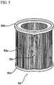
- FIG. 7is a perspective view showing a modified shape of a filter case according to the present invention.
- FIG. 2is a front perspective view of a dust collecting unit of a cyclonic vacuum cleaner according to the present invention
- FIG. 3is an exploded perspective view of the dust collecting unit of the cyclonic vacuum cleaner according to the present invention.
- the vacuum cleaner of the present inventioncomprises a cover 30 for covering an upper end of the dust collecting unit 11 to protect inner parts and hermetically sealing the unit to prevent sucked air from leaking out, a filter assembly 40 installed downward from the cover 30 around an outlet 31 formed near the center of the cover, and a dust collecting casing 80 attached to a bottom side of the cover 30 .
- the outlet 31through which clean air with dust and dirt filtered out from the air sucked in the dust collecting casing 80 is discharged.
- the filter assembly 40in which a fine filtering structure is implemented is positioned below the outlet 31 to filter out fine particles.
- the filter assembly 40is cylindrical and is formed with the fine filtering structure on an outer periphery thereof. The air flowing into the filter assembly 40 is filtrated by the filter assembly 40 and then discharged to the outside through the outlet 31 .
- the dust collecting casing 80comprises an inlet 71 through which air is introduced from the main body of the vacuum cleaner into the dust collecting unit, a cylindrical dust separation chamber 70 in which the air sucked through the inlet 71 swirls by a centrifugal force and the dust and dirt are separated from the air by their own weight, and a main dust collecting chamber 50 which is defined in the dust separation chamber 70 below a dust separating plate 73 SO that the dust and dirt dropped by their own weight are accumulated in the dust collecting chamber through a predetermined opening 74 .
- the filter assembly 40comprises a filter casing 41 with a plurality of holes formed on an outer periphery thereof and a large air discharge opening formed at an upper end thereof, a pleated filter 42 mounted into the filter casing 41 , and a filter cover 43 which is attached to the upper end of the filter casing 41 to allow the filter casing 41 to be fixed to a bottom surface of the cover 30 .
- the filter assembly 40will be operated in such a manner that fine dust is filtered out by the pleated filter 42 after relatively large dust has been filtered out while the air containing the dust swirls in the dust separating chamber 70 , and the clean air from which the fine dust has been separated by the pleated filter 42 is discharged to the outside through the outlet 31 .
- FIG. 4is an exploded perspective view of the filter assembly for a vacuum cleaner according to a preferred embodiment of the present invention.
- the filter assembly 40comprises a cylindrical filter case 81 with a plurality of air vent holes formed on an outer periphery thereof, a fine filter 82 attached to the outer periphery of the filter case 81 , a pleated filter 83 mounted into the filter case 81 , and a filter cover 84 attached to an upper end of the filter case 81 .
- a lower end of the filter case 81is closed whereas the upper end thereof is opened to allow air to be discharged to the outside.
- the positions of air vent holes and air discharge opening of the filter casing 81may vary according to a specific shape of the dust collecting unit for filtering out the relative large dust.
- the fine filter 82is a mesh filter for finely filtering out the fine dust after the relatively large dust has been filtered out by the cyclonic operation.
- the dust to be filteredgenerally adheres to an outer surface of the fine filter 82 .
- the fine filter 82may be attached either to the whole outer periphery of the filter case 81 or to only specific regions of the filter case using the adhesive in order to prevent the fine holes thereof from being blocked while the fine filter 82 is mounted to the filter case 81 .
- the fine filter 82 and the pleated filter 83function as primary and secondary filters, respectively.
- the filter assembly with the two filterscan provide the dust collecting unit with a dual filtering function in addition to the cyclonic dust collection function.
- the pleated filter 83can be fitted and securely seated into the filter case 81 , and it can also easily detach from the filter case 81 when a user wishes to remove the dust and dirt therefrom.
- the filter cover 84is used to attach the filter assembly 40 to the dust collecting unit 11 .
- a specific shape, structure and arrangement of the filter cover 84can vary according to a specific structure and shape of the dust collecting unit.
- the relatively large dustis filtered by a cyclonic swirling phenomenon generated in the dust collecting unit, and then, only fine dust remains in the air.
- Such fine dustis first filtered by the fine filter 82 . That is, the fine dust contained in the air is first filtered out to a nearly perfect level.
- the fine dust that has not yet been filtered by the fine filter 82is perfectly filtered by the pleated filter 83 and then discharged through the opening formed at the upper end of the filter assembly 40 .
- the fine filter 82can be more easily cleaned as compared with in the prior art.
- FIG. 5shows a preferred example of the pleated filter.
- the pleated filter 83comprises pleated portions 83 a that are closely pleated several times to increase a surface area to be contacted with the dust, and flexible fixing portions 83 b for fixing upper and lower ends of the pleated portions 83 a.
- the pleated portions 83 abe generally made of a vulcanized fiber etc. so that it can be prevented from being easily deformed by a suction force of a motor (not shown) and can also be washed with water for its semi-permanent use.
- the flexible fixing portions 83 bare made of rubber or urethane such that their shapes can be flexibly changed in accordance with an external pressure.
- the flexible fixing portions 83 bare attached to the upper and lower ends of the pleated portions 83 a, respectively, so that the pleated portions 83 a can be maintained to their specific shapes. Desired regions of the pleated portions 83 a may become relatively widened by modifying the flexible fixing portions 83 b according to a desired shape as shown in this figure.
- the desired regions of the pleated portions 83 acan be widened by the flexible fixing portions 83 b, the dust held between the widened pleated portions 83 c can be easily removed using a brush, etc.
- FIG. 6is an exploded perspective view of a filter assembly for a vacuum cleaner according to another preferred embodiment of the present invention.
- the filter assembly of this embodimentis identical with the aforementioned embodiment in many respects. That is, a fine filter 92 , a filter case 91 and a filter cover 94 of this embodiment are the same as those of the aforementioned embodiment, except that the pleated filter 83 is replaced with a porous filter 93 in this embodiment.
- a porous filter 93sponge or the like may be used.
- the porous filter 93is generally made of a resin in which a plurality of holes are formed to filter out the dust.
- the fine dust and dirt that has not yet been filtered by the fine filter 92can also be perfectly filtered by the porous filter 93 .
- any shapes of secondary filterscan be used in the filter assembly regardless of the kinds thereof.
- the fine dust and dirt adhering to the surface of the fine filter 92can be easily cleaned or washed, and the life of the porous filter 93 can also be prolonged since a large amount of the dust and dirt is not accumulated in the porous filter 93 due to the fine filter 92 .
- FIG. 7is a perspective view showing a modified example of the filter case 81 or 91 .
- Any one of the filter cases 81 and 91is installed at the center of the dust collecting casing 80 , and the air sucked from the inlet 71 swirls around the filter case in a cyclonic manner.
- a portion of the filter caseis formed with a closed structure through which air does not pass. That is, a plurality of openings 81 b serving as air vent holes are formed at a portion of the outer periphery of the filter case, whereas a closed surface 81 a with no openings is formed at the other portion of the outer periphery of the filter case.
- the filter case so constructedis installed such that the flow of air introduced from the inlet 71 of the dust collecting casing 80 is directed to the closed surface 81 a, it is possible to prevent the introduced air from directly flowing into the filter assembly 40 without the cyclonic dust collection during the swirling process of the introduced air. Therefore, dust collection efficiency of the vacuum cleaner can be further maximized.
- the present inventioncan be applied to various types of the vacuum cleaners, and particularly, to the cyclonic vacuum cleaner so that convenience of use can be further improved.
- the present inventionthere is an advantage in that it is possible to easily remove the dust and dirt accumulated in the filter assembly during the process of filtering the fine dust contained in the air. Further, the expected life span of the filter assembly can be more prolonged because the fine filter can be used semi-permanently. Furthermore, the cleaning efficiency of the vacuum cleaner can also be improved due to the dual filtering function in addition to the cyclonic dust collection of the dust collection unit.
Landscapes
- Engineering & Computer Science (AREA)
- Mechanical Engineering (AREA)
- Chemical & Material Sciences (AREA)
- Chemical Kinetics & Catalysis (AREA)
- Filters For Electric Vacuum Cleaners (AREA)
Abstract
Description
Claims (17)
Applications Claiming Priority (4)
| Application Number | Priority Date | Filing Date | Title |
|---|---|---|---|
| KR1020030046281AKR100562112B1 (en) | 2003-07-09 | 2003-07-09 | Filter structure of vacuum cleaner |
| KR2003-0046281 | 2003-07-09 | ||
| KR2003-0052184 | 2003-07-29 | ||
| KR1020030052184AKR100587096B1 (en) | 2003-07-29 | 2003-07-29 | Dust collection unit of vacuum cleaner |
Publications (2)
| Publication Number | Publication Date |
|---|---|
| US20050005390A1 US20050005390A1 (en) | 2005-01-13 |
| US7552506B2true US7552506B2 (en) | 2009-06-30 |
Family
ID=33455699
Family Applications (1)
| Application Number | Title | Priority Date | Filing Date |
|---|---|---|---|
| US10/788,296Expired - Fee RelatedUS7552506B2 (en) | 2003-07-09 | 2004-03-01 | Filter assembly for vacuum cleaner |
Country Status (6)
| Country | Link |
|---|---|
| US (1) | US7552506B2 (en) |
| EP (1) | EP1495708B1 (en) |
| JP (1) | JP4520184B2 (en) |
| DE (2) | DE04013152T1 (en) |
| ES (1) | ES2234457T3 (en) |
| RU (1) | RU2262287C1 (en) |
Cited By (6)
| Publication number | Priority date | Publication date | Assignee | Title |
|---|---|---|---|---|
| US20130160232A1 (en)* | 2011-12-22 | 2013-06-27 | Dyson Technology Limited | Vacuum cleaner |
| US20140373306A1 (en)* | 2008-12-08 | 2014-12-25 | Emerson Electric Co. | Slide out drum with filter for a wet/dry vacuum appliance |
| US10238253B2 (en) | 2012-08-08 | 2019-03-26 | Bissell Homecare, Inc. | Solid fragrance carrier and method of use in a vacuum cleaner |
| US10368706B1 (en) | 2018-07-17 | 2019-08-06 | Shop Vac Corporation | Vacuum filter having annular catch |
| US11376541B2 (en) | 2016-12-15 | 2022-07-05 | Cummins Filtration Ip, Inc. | Tetrahedral filter media |
| US11439943B2 (en) | 2016-10-20 | 2022-09-13 | Cummins Filtration Ip, Inc. | Interrupted, directional emboss of flat sheet |
Families Citing this family (15)
| Publication number | Priority date | Publication date | Assignee | Title |
|---|---|---|---|---|
| SE0300355D0 (en) | 2003-02-10 | 2003-02-10 | Electrolux Ab | Hand held vacuum cleaner |
| ATE438456T1 (en) | 2004-08-16 | 2009-08-15 | Lg Electronics Inc | FILTER UNIT OF AN AIR CONDITIONER |
| US20070209334A1 (en)* | 2006-03-10 | 2007-09-13 | Gbd Corp. | Vacuum cleaner with a removable screen |
| SE0600668L (en)* | 2006-03-24 | 2007-10-23 | Electrolux Abp | Handheld vacuum cleaner |
| SE531125C2 (en)* | 2007-01-19 | 2008-12-23 | Electrolux Ab | Improvements in air flow losses in a vacuum cleaner |
| WO2007117197A1 (en)* | 2006-04-10 | 2007-10-18 | Aktiebolaget Electrolux | A vacuum cleaner |
| US20080040883A1 (en)* | 2006-04-10 | 2008-02-21 | Jonas Beskow | Air Flow Losses in a Vacuum Cleaners |
| EP2007264B1 (en) | 2006-04-10 | 2019-03-13 | Aktiebolaget Electrolux | Vacuum cleaner with filter cleaning means |
| CN101588743B (en)* | 2007-01-23 | 2013-04-10 | 伊莱克斯公司 | vacuum cleaner head |
| US20090100809A1 (en)* | 2007-10-23 | 2009-04-23 | Baldwin Jr Donald W | Filter assembly for removing particulates in an exhaust gas in a fuel engine |
| DE102009055090B4 (en)* | 2009-12-21 | 2012-01-26 | Bernhard Ringler Apparate-Bau Gmbh | Device for the extraction of powdery or dusty material |
| JP4932025B2 (en)* | 2010-10-15 | 2012-05-16 | シャープ株式会社 | Vacuum cleaner |
| US11672395B2 (en)* | 2021-01-06 | 2023-06-13 | Omachron Intellectual Property Inc. | Surface cleaning apparatus |
| KR102327196B1 (en)* | 2018-05-03 | 2021-11-17 | 엘지전자 주식회사 | Cleaner |
| PT119127A (en)* | 2023-12-12 | 2025-06-12 | Cespu Cooperativa De Ensino Superior Politecnico E Univ Crl | MOBILE APPLICATION FOR USE IN TUTORING AND MENTORING NETWORKS |
Citations (35)
| Publication number | Priority date | Publication date | Assignee | Title |
|---|---|---|---|---|
| US2784801A (en)* | 1954-05-27 | 1957-03-12 | Theodore G Lunde | Combined air cleaner and vent |
| US3189179A (en)* | 1962-07-18 | 1965-06-15 | Gen Motors Corp | Replaceable filter cartridge for a dry cleaner |
| US3423909A (en)* | 1967-09-28 | 1969-01-28 | Novo Ind Corp | Air cleaner with improved filter element assembly |
| US3552553A (en) | 1967-10-06 | 1971-01-05 | Torite Enterprises Inc | Dual media filtration cartridge |
| GB1436391A (en) | 1972-09-05 | 1976-05-19 | Mitsubishi Electric Corp | Electric suction cleaner |
| US4032457A (en)* | 1975-06-04 | 1977-06-28 | Fibredyne, Inc. | Plural stage filter cartridge wherein at least one stage comprises pulverized particulate material |
| JPS5279370A (en) | 1975-12-25 | 1977-07-04 | Matsushita Electric Ind Co Ltd | Dust collecting device |
| US4303426A (en)* | 1980-03-14 | 1981-12-01 | Robert Battis | Automobile air filter having replaceable and readily disposable filter element |
| US4314832A (en)* | 1980-07-24 | 1982-02-09 | Donaldson Company, Inc. | Air cleaner with cartridge suspension |
| US4726825A (en) | 1985-02-22 | 1988-02-23 | Gpac, Inc. | Disposable HEPA filtration device |
| US4838903A (en) | 1987-05-20 | 1989-06-13 | Ceco Filters, Inc. | Multi-phase thick-bed filter |
| RU2050825C1 (en) | 1993-04-20 | 1995-12-27 | Акционерное общество "Уралэлектротяжмаш" | Dust collector for the vacuum cleaner |
| JPH0871316A (en) | 1994-09-02 | 1996-03-19 | Human Techno Kk | Filter element and filter |
| US5762669A (en) | 1990-10-19 | 1998-06-09 | Donaldson Company, Inc. | Filtration arrangement |
| US5972063A (en)* | 1995-04-21 | 1999-10-26 | Donaldson Company, Inc. | Air filtration arrangement and method |
| EP0983743A2 (en) | 1998-08-31 | 2000-03-08 | Shop Vac Corporation | Dual filter assembly for a vacuum cleaner |
| JP2000167314A (en) | 1998-12-10 | 2000-06-20 | Yamashin Kogyo Kk | Filter element |
| US6289553B1 (en) | 1997-12-17 | 2001-09-18 | Notetry Limited | Vacuum cleaner |
| JP2001269297A (en) | 2000-03-24 | 2001-10-02 | Sharp Corp | Electric vacuum cleaner |
| US6341404B1 (en) | 2000-01-13 | 2002-01-29 | Royal Appliance Mfg. Co. | Upright vacuum cleaner with cyclonic airflow pathway |
| EP1181886A2 (en) | 2000-08-19 | 2002-02-27 | Lg Electronics Inc. | Cyclone dust collector and vacuum cleaner using such dust collector |
| US20020095741A1 (en)* | 2001-01-22 | 2002-07-25 | Mineyuki Inoue | Cyclonic vacuum cleaner |
| JP2002253455A (en) | 2002-02-12 | 2002-09-10 | Twinbird Corp | Cyclone type cleaner |
| JP2002331208A (en) | 2001-05-09 | 2002-11-19 | Konan Tokushu Sangyo Kk | Filter device for EDM |
| US6484350B2 (en)* | 1999-12-08 | 2002-11-26 | Shell Electric Mfg. (Holdings) Co. Ltd. | Bagless canister vacuum cleaner |
| US20020194695A1 (en) | 2001-01-12 | 2002-12-26 | Royal Appliance Mfg. Co. | Vacuum cleaner with noise suppression features |
| AU758164B1 (en) | 2000-12-13 | 2003-03-20 | Lg Electronics Inc. | Filter mounting device for vacuum cleaner |
| US6558453B2 (en)* | 2000-01-14 | 2003-05-06 | White Consolidated Industries, Inc. | Bagless dustcup |
| US20030084536A1 (en)* | 2001-11-06 | 2003-05-08 | Billy Yung | Bagless vacuum cleaner with improved dirt removal system |
| EP1323370A2 (en) | 2001-12-18 | 2003-07-02 | SANYO ELECTRIC Co., Ltd. | Vacuum cleaner |
| US20040074041A1 (en)* | 2002-10-11 | 2004-04-22 | Overvaag Chad D. | Bagless dust box for vacuum cleaner |
| US20040093684A1 (en)* | 2002-11-15 | 2004-05-20 | Lg Electronics Inc. | Dust and dirt collecting unit for vacuum cleaner |
| US6913635B2 (en)* | 2002-11-22 | 2005-07-05 | Samsung Gwangju Electronics Co. Ltd | Dust collecting filter of vacuum cleaner and vacuum cleaner having the same |
| US7115150B2 (en)* | 2000-09-05 | 2006-10-03 | Donaldson Company, Inc. | Mist filtration arrangement utilizing fine fiber layer in contact with media having a pleated construction and floor filter method |
| US7135051B2 (en)* | 2003-06-05 | 2006-11-14 | Baldinger Russell L | Dirt cup filter with pre-filtration cap |
- 2004
- 2004-03-01USUS10/788,296patent/US7552506B2/ennot_activeExpired - Fee Related
- 2004-03-09JPJP2004065907Apatent/JP4520184B2/ennot_activeExpired - Fee Related
- 2004-03-23RURU2004108668/12Apatent/RU2262287C1/ennot_activeIP Right Cessation
- 2004-06-03ESES04013152Tpatent/ES2234457T3/ennot_activeExpired - Lifetime
- 2004-06-03DEDE04013152Tpatent/DE04013152T1/enactivePending
- 2004-06-03EPEP04013152Apatent/EP1495708B1/ennot_activeExpired - Lifetime
- 2004-06-03DEDE602004018710Tpatent/DE602004018710D1/ennot_activeExpired - Fee Related
Patent Citations (36)
| Publication number | Priority date | Publication date | Assignee | Title |
|---|---|---|---|---|
| US2784801A (en)* | 1954-05-27 | 1957-03-12 | Theodore G Lunde | Combined air cleaner and vent |
| US3189179A (en)* | 1962-07-18 | 1965-06-15 | Gen Motors Corp | Replaceable filter cartridge for a dry cleaner |
| US3423909A (en)* | 1967-09-28 | 1969-01-28 | Novo Ind Corp | Air cleaner with improved filter element assembly |
| US3552553A (en) | 1967-10-06 | 1971-01-05 | Torite Enterprises Inc | Dual media filtration cartridge |
| GB1436391A (en) | 1972-09-05 | 1976-05-19 | Mitsubishi Electric Corp | Electric suction cleaner |
| US4032457A (en)* | 1975-06-04 | 1977-06-28 | Fibredyne, Inc. | Plural stage filter cartridge wherein at least one stage comprises pulverized particulate material |
| JPS5279370A (en) | 1975-12-25 | 1977-07-04 | Matsushita Electric Ind Co Ltd | Dust collecting device |
| US4303426A (en)* | 1980-03-14 | 1981-12-01 | Robert Battis | Automobile air filter having replaceable and readily disposable filter element |
| US4314832A (en)* | 1980-07-24 | 1982-02-09 | Donaldson Company, Inc. | Air cleaner with cartridge suspension |
| US4726825A (en) | 1985-02-22 | 1988-02-23 | Gpac, Inc. | Disposable HEPA filtration device |
| US4838903A (en) | 1987-05-20 | 1989-06-13 | Ceco Filters, Inc. | Multi-phase thick-bed filter |
| US5762669A (en) | 1990-10-19 | 1998-06-09 | Donaldson Company, Inc. | Filtration arrangement |
| RU2050825C1 (en) | 1993-04-20 | 1995-12-27 | Акционерное общество "Уралэлектротяжмаш" | Dust collector for the vacuum cleaner |
| JPH0871316A (en) | 1994-09-02 | 1996-03-19 | Human Techno Kk | Filter element and filter |
| US5972063A (en)* | 1995-04-21 | 1999-10-26 | Donaldson Company, Inc. | Air filtration arrangement and method |
| US6289553B1 (en) | 1997-12-17 | 2001-09-18 | Notetry Limited | Vacuum cleaner |
| EP0983743A2 (en) | 1998-08-31 | 2000-03-08 | Shop Vac Corporation | Dual filter assembly for a vacuum cleaner |
| JP2000167314A (en) | 1998-12-10 | 2000-06-20 | Yamashin Kogyo Kk | Filter element |
| US6484350B2 (en)* | 1999-12-08 | 2002-11-26 | Shell Electric Mfg. (Holdings) Co. Ltd. | Bagless canister vacuum cleaner |
| USRE39473E1 (en)* | 2000-01-13 | 2007-01-23 | Royal Appliance Mfg. Co. | Upright vacuum cleaner with cyclonic airflow pathway |
| US6341404B1 (en) | 2000-01-13 | 2002-01-29 | Royal Appliance Mfg. Co. | Upright vacuum cleaner with cyclonic airflow pathway |
| US6558453B2 (en)* | 2000-01-14 | 2003-05-06 | White Consolidated Industries, Inc. | Bagless dustcup |
| JP2001269297A (en) | 2000-03-24 | 2001-10-02 | Sharp Corp | Electric vacuum cleaner |
| EP1181886A2 (en) | 2000-08-19 | 2002-02-27 | Lg Electronics Inc. | Cyclone dust collector and vacuum cleaner using such dust collector |
| US7115150B2 (en)* | 2000-09-05 | 2006-10-03 | Donaldson Company, Inc. | Mist filtration arrangement utilizing fine fiber layer in contact with media having a pleated construction and floor filter method |
| AU758164B1 (en) | 2000-12-13 | 2003-03-20 | Lg Electronics Inc. | Filter mounting device for vacuum cleaner |
| US20020194695A1 (en) | 2001-01-12 | 2002-12-26 | Royal Appliance Mfg. Co. | Vacuum cleaner with noise suppression features |
| US20020095741A1 (en)* | 2001-01-22 | 2002-07-25 | Mineyuki Inoue | Cyclonic vacuum cleaner |
| JP2002331208A (en) | 2001-05-09 | 2002-11-19 | Konan Tokushu Sangyo Kk | Filter device for EDM |
| US20030084536A1 (en)* | 2001-11-06 | 2003-05-08 | Billy Yung | Bagless vacuum cleaner with improved dirt removal system |
| EP1323370A2 (en) | 2001-12-18 | 2003-07-02 | SANYO ELECTRIC Co., Ltd. | Vacuum cleaner |
| JP2002253455A (en) | 2002-02-12 | 2002-09-10 | Twinbird Corp | Cyclone type cleaner |
| US20040074041A1 (en)* | 2002-10-11 | 2004-04-22 | Overvaag Chad D. | Bagless dust box for vacuum cleaner |
| US20040093684A1 (en)* | 2002-11-15 | 2004-05-20 | Lg Electronics Inc. | Dust and dirt collecting unit for vacuum cleaner |
| US6913635B2 (en)* | 2002-11-22 | 2005-07-05 | Samsung Gwangju Electronics Co. Ltd | Dust collecting filter of vacuum cleaner and vacuum cleaner having the same |
| US7135051B2 (en)* | 2003-06-05 | 2006-11-14 | Baldinger Russell L | Dirt cup filter with pre-filtration cap |
Cited By (14)
| Publication number | Priority date | Publication date | Assignee | Title |
|---|---|---|---|---|
| US20140373306A1 (en)* | 2008-12-08 | 2014-12-25 | Emerson Electric Co. | Slide out drum with filter for a wet/dry vacuum appliance |
| US9572465B2 (en)* | 2008-12-08 | 2017-02-21 | Emerson Electric Co. | Slide out drum with filter for a wet/dry vacuum appliance |
| US10660495B2 (en) | 2011-12-22 | 2020-05-26 | Dyson Technology Limited | Vacuum cleaner |
| US9211046B2 (en)* | 2011-12-22 | 2015-12-15 | Dyson Technology Limited | Vacuum cleaner |
| US20160051106A1 (en)* | 2011-12-22 | 2016-02-25 | Dyson Technology Limited | Vacuum cleaner |
| US9788697B2 (en)* | 2011-12-22 | 2017-10-17 | Dyson Technology Limited | Vacuum cleaner |
| US20130160232A1 (en)* | 2011-12-22 | 2013-06-27 | Dyson Technology Limited | Vacuum cleaner |
| US10238253B2 (en) | 2012-08-08 | 2019-03-26 | Bissell Homecare, Inc. | Solid fragrance carrier and method of use in a vacuum cleaner |
| US10702109B2 (en) | 2012-08-08 | 2020-07-07 | Bissell Inc. | Solid fragrance carrier and method of use in a vacuum cleaner |
| US11439943B2 (en) | 2016-10-20 | 2022-09-13 | Cummins Filtration Ip, Inc. | Interrupted, directional emboss of flat sheet |
| US11865488B2 (en) | 2016-10-20 | 2024-01-09 | Cummins Filtration Ip, Inc. | Interrupted, directional emboss of flat sheet |
| US11376541B2 (en) | 2016-12-15 | 2022-07-05 | Cummins Filtration Ip, Inc. | Tetrahedral filter media |
| US10368706B1 (en) | 2018-07-17 | 2019-08-06 | Shop Vac Corporation | Vacuum filter having annular catch |
| US11304579B2 (en) | 2018-07-17 | 2022-04-19 | Shop Vac Corporation | Vacuum filter having annular catch |
Also Published As
| Publication number | Publication date |
|---|---|
| ES2234457T3 (en) | 2009-05-01 |
| EP1495708B1 (en) | 2008-12-31 |
| DE602004018710D1 (en) | 2009-02-12 |
| EP1495708A3 (en) | 2006-06-07 |
| EP1495708A2 (en) | 2005-01-12 |
| RU2262287C1 (en) | 2005-10-20 |
| DE04013152T1 (en) | 2005-06-23 |
| ES2234457T1 (en) | 2005-07-01 |
| JP2005028101A (en) | 2005-02-03 |
| US20050005390A1 (en) | 2005-01-13 |
| JP4520184B2 (en) | 2010-08-04 |
Similar Documents
| Publication | Publication Date | Title |
|---|---|---|
| US7552506B2 (en) | Filter assembly for vacuum cleaner | |
| EP2351504B1 (en) | Upright vacuum cleaner with cyclonic airflow | |
| KR100485705B1 (en) | Dust collecting container for vacuum cleaner | |
| US7086119B2 (en) | Dust collecting unit of vacuum cleaner | |
| KR200377056Y1 (en) | Dust and dirt collecting unit for vacuum cleaner | |
| GB2395448A (en) | A reusable dust collecting filter | |
| EP2034875A2 (en) | Single stage cyclone vacuum cleaner | |
| CA2466823C (en) | Dust collecting apparatus for a vacuum cleaner having two cyclone chambers | |
| US20040098826A1 (en) | Dust collecting filter for vacuum cleaner and vacuum cleaner having the same | |
| WO2007146444A9 (en) | Filter cleaning system for a vacuum cleaner | |
| US20060277712A1 (en) | Vacuum cleaner | |
| US20040064912A1 (en) | Dust and dirt collecting unit for vacuum cleaner | |
| KR100562112B1 (en) | Filter structure of vacuum cleaner | |
| WO2020262599A1 (en) | Electric vacuum cleaner | |
| KR200344457Y1 (en) | a vacuum cleaner for a vehicle | |
| KR20060022954A (en) | Vacuum cleaner | |
| KR20060022955A (en) | Vacuum cleaner | |
| KR100587096B1 (en) | Dust collection unit of vacuum cleaner | |
| KR20040080093A (en) | Exhausting filter structure for vacuum cleaner | |
| KR200291449Y1 (en) | Filtering device for vacuum cleaner | |
| KR20050119740A (en) | A dust collector for vacuum cleaner | |
| KR20050119741A (en) | A dust collector for vacuum cleaner | |
| KR20060018603A (en) | Vacuum cleaner |
Legal Events
| Date | Code | Title | Description |
|---|---|---|---|
| AS | Assignment | Owner name:LG ELECTRONICS INC., KOREA, REPUBLIC OF Free format text:ASSIGNMENT OF ASSIGNORS INTEREST;ASSIGNORS:LEE, YUN-SEOK;JEONG, HOI-KIL;REEL/FRAME:015030/0782 Effective date:20040224 | |
| AS | Assignment | Owner name:LG ELECTRONICS INC., KOREA, REPUBLIC OF Free format text:ASSIGNMENT OF ASSIGNORS INTEREST;ASSIGNOR:LEE, JAE-GEUN;REEL/FRAME:018415/0091 Effective date:20060908 | |
| FEPP | Fee payment procedure | Free format text:PAYOR NUMBER ASSIGNED (ORIGINAL EVENT CODE: ASPN); ENTITY STATUS OF PATENT OWNER: LARGE ENTITY | |
| STCF | Information on status: patent grant | Free format text:PATENTED CASE | |
| FEPP | Fee payment procedure | Free format text:PAYER NUMBER DE-ASSIGNED (ORIGINAL EVENT CODE: RMPN); ENTITY STATUS OF PATENT OWNER: LARGE ENTITY Free format text:PAYOR NUMBER ASSIGNED (ORIGINAL EVENT CODE: ASPN); ENTITY STATUS OF PATENT OWNER: LARGE ENTITY | |
| FPAY | Fee payment | Year of fee payment:4 | |
| FPAY | Fee payment | Year of fee payment:8 | |
| FEPP | Fee payment procedure | Free format text:MAINTENANCE FEE REMINDER MAILED (ORIGINAL EVENT CODE: REM.); ENTITY STATUS OF PATENT OWNER: LARGE ENTITY | |
| LAPS | Lapse for failure to pay maintenance fees | Free format text:PATENT EXPIRED FOR FAILURE TO PAY MAINTENANCE FEES (ORIGINAL EVENT CODE: EXP.); ENTITY STATUS OF PATENT OWNER: LARGE ENTITY | |
| STCH | Information on status: patent discontinuation | Free format text:PATENT EXPIRED DUE TO NONPAYMENT OF MAINTENANCE FEES UNDER 37 CFR 1.362 | |
| FP | Lapsed due to failure to pay maintenance fee | Effective date:20210630 |