US7550012B2 - Stent for implantation - Google Patents
Stent for implantationDownload PDFInfo
- Publication number
- US7550012B2 US7550012B2US11/218,210US21821005AUS7550012B2US 7550012 B2US7550012 B2US 7550012B2US 21821005 AUS21821005 AUS 21821005AUS 7550012 B2US7550012 B2US 7550012B2
- Authority
- US
- United States
- Prior art keywords
- stent
- wire
- coating
- rod
- catheter
- Prior art date
- Legal status (The legal status is an assumption and is not a legal conclusion. Google has not performed a legal analysis and makes no representation as to the accuracy of the status listed.)
- Active, expires
Links
- 238000002513implantationMethods0.000titleclaimsdescription9
- 238000000034methodMethods0.000claimsabstractdescription47
- 238000000576coating methodMethods0.000claimsdescription24
- 210000000626ureterAnatomy0.000claimsdescription23
- 239000011248coating agentSubstances0.000claimsdescription21
- 239000003814drugSubstances0.000claimsdescription15
- 229940079593drugDrugs0.000claimsdescription15
- 239000012530fluidSubstances0.000claimsdescription14
- HTTJABKRGRZYRN-UHFFFAOYSA-NHeparinChemical compoundOC1C(NC(=O)C)C(O)OC(COS(O)(=O)=O)C1OC1C(OS(O)(=O)=O)C(O)C(OC2C(C(OS(O)(=O)=O)C(OC3C(C(O)C(O)C(O3)C(O)=O)OS(O)(=O)=O)C(CO)O2)NS(O)(=O)=O)C(C(O)=O)O1HTTJABKRGRZYRN-UHFFFAOYSA-N0.000claimsdescription8
- 229960002897heparinDrugs0.000claimsdescription8
- 229920000669heparinPolymers0.000claimsdescription8
- 239000000463materialSubstances0.000claimsdescription7
- 230000000845anti-microbial effectEffects0.000claimsdescription5
- 239000004599antimicrobialSubstances0.000claimsdescription5
- 239000000730antalgic agentSubstances0.000claimsdescription3
- 229910000619316 stainless steelInorganic materials0.000claimsdescription2
- RTAQQCXQSZGOHL-UHFFFAOYSA-NTitaniumChemical compound[Ti]RTAQQCXQSZGOHL-UHFFFAOYSA-N0.000claimsdescription2
- 239000003193general anesthetic agentSubstances0.000claimsdescription2
- 229910000856hastalloyInorganic materials0.000claimsdescription2
- 229910001119inconels 625Inorganic materials0.000claimsdescription2
- 229910052719titaniumInorganic materials0.000claimsdescription2
- 239000010936titaniumSubstances0.000claimsdescription2
- 238000004804windingMethods0.000claimsdescription2
- 230000000202analgesic effectEffects0.000claims3
- 230000003444anaesthetic effectEffects0.000claims2
- 150000001875compoundsChemical class0.000claims2
- 230000002440hepatic effectEffects0.000abstractdescription2
- 238000002324minimally invasive surgeryMethods0.000abstractdescription2
- 230000002792vascularEffects0.000abstractdescription2
- 210000003445biliary tractAnatomy0.000abstract1
- 210000001035gastrointestinal tractAnatomy0.000abstract1
- 210000003734kidneyAnatomy0.000description12
- -1e.g.Substances0.000description8
- 210000003708urethraAnatomy0.000description7
- 230000006835compressionEffects0.000description5
- 238000007906compressionMethods0.000description5
- 230000009977dual effectEffects0.000description4
- 150000003839saltsChemical class0.000description4
- 210000002700urineAnatomy0.000description4
- YMWUJEATGCHHMB-UHFFFAOYSA-NDichloromethaneChemical compoundClCClYMWUJEATGCHHMB-UHFFFAOYSA-N0.000description3
- XYYVYLMBEZUESM-UHFFFAOYSA-NdihydrocodeineNatural productsC1C(N(CCC234)C)C2C=CC(=O)C3OC2=C4C1=CC=C2OCXYYVYLMBEZUESM-UHFFFAOYSA-N0.000description3
- 229920002313fluoropolymerPolymers0.000description3
- 239000004811fluoropolymerSubstances0.000description3
- 238000003780insertionMethods0.000description3
- 230000037431insertionEffects0.000description3
- 230000007774longtermEffects0.000description3
- DYKFCLLONBREIL-KVUCHLLUSA-NminocyclineChemical compoundC([C@H]1C2)C3=C(N(C)C)C=CC(O)=C3C(=O)C1=C(O)[C@@]1(O)[C@@H]2[C@H](N(C)C)C(O)=C(C(N)=O)C1=ODYKFCLLONBREIL-KVUCHLLUSA-N0.000description3
- 229960004023minocyclineDrugs0.000description3
- 239000000203mixtureSubstances0.000description3
- 229940021182non-steroidal anti-inflammatory drugDrugs0.000description3
- 229920003023plasticPolymers0.000description3
- 239000004033plasticSubstances0.000description3
- 229920001343polytetrafluoroethylenePolymers0.000description3
- 239000004810polytetrafluoroethyleneSubstances0.000description3
- JQXXHWHPUNPDRT-WLSIYKJHSA-NrifampicinChemical compoundO([C@](C1=O)(C)O/C=C/[C@@H]([C@H]([C@@H](OC(C)=O)[C@H](C)[C@H](O)[C@H](C)[C@@H](O)[C@@H](C)\C=C\C=C(C)/C(=O)NC=2C(O)=C3C([O-])=C4C)C)OC)C4=C1C3=C(O)C=2\C=N\N1CC[NH+](C)CC1JQXXHWHPUNPDRT-WLSIYKJHSA-N0.000description3
- 229960001225rifampicinDrugs0.000description3
- 238000002560therapeutic procedureMethods0.000description3
- BSYNRYMUTXBXSQ-UHFFFAOYSA-NAspirinChemical compoundCC(=O)OC1=CC=CC=C1C(O)=OBSYNRYMUTXBXSQ-UHFFFAOYSA-N0.000description2
- AOJJSUZBOXZQNB-TZSSRYMLSA-NDoxorubicinChemical compoundO([C@H]1C[C@@](O)(CC=2C(O)=C3C(=O)C=4C=CC=C(C=4C(=O)C3=C(O)C=21)OC)C(=O)CO)[C@H]1C[C@H](N)[C@H](O)[C@H](C)O1AOJJSUZBOXZQNB-TZSSRYMLSA-N0.000description2
- 208000031481Pathologic ConstrictionDiseases0.000description2
- KAESVJOAVNADME-UHFFFAOYSA-NPyrroleChemical compoundC=1C=CNC=1KAESVJOAVNADME-UHFFFAOYSA-N0.000description2
- XEFQLINVKFYRCS-UHFFFAOYSA-NTriclosanChemical compoundOC1=CC(Cl)=CC=C1OC1=CC=C(Cl)C=C1ClXEFQLINVKFYRCS-UHFFFAOYSA-N0.000description2
- 208000027418Wounds and injuryDiseases0.000description2
- 229960001138acetylsalicylic acidDrugs0.000description2
- 239000002253acidSubstances0.000description2
- 239000000853adhesiveSubstances0.000description2
- 230000001070adhesive effectEffects0.000description2
- 229910045601alloyInorganic materials0.000description2
- 239000000956alloySubstances0.000description2
- 229940035676analgesicsDrugs0.000description2
- 210000000941bileAnatomy0.000description2
- 210000000013bile ductAnatomy0.000description2
- 238000005219brazingMethods0.000description2
- OROGSEYTTFOCAN-DNJOTXNNSA-NcodeineChemical compoundC([C@H]1[C@H](N(CC[C@@]112)C)C3)=C[C@H](O)[C@@H]1OC1=C2C3=CC=C1OCOROGSEYTTFOCAN-DNJOTXNNSA-N0.000description2
- UREBDLICKHMUKA-CXSFZGCWSA-NdexamethasoneChemical compoundC1CC2=CC(=O)C=C[C@]2(C)[C@]2(F)[C@@H]1[C@@H]1C[C@@H](C)[C@@](C(=O)CO)(O)[C@@]1(C)C[C@@H]2OUREBDLICKHMUKA-CXSFZGCWSA-N0.000description2
- 238000002405diagnostic procedureMethods0.000description2
- 230000000916dilatatory effectEffects0.000description2
- OROGSEYTTFOCAN-UHFFFAOYSA-NhydrocodoneNatural productsC1C(N(CCC234)C)C2C=CC(O)C3OC2=C4C1=CC=C2OCOROGSEYTTFOCAN-UHFFFAOYSA-N0.000description2
- CGIGDMFJXJATDK-UHFFFAOYSA-NindomethacinChemical compoundCC1=C(CC(O)=O)C2=CC(OC)=CC=C2N1C(=O)C1=CC=C(Cl)C=C1CGIGDMFJXJATDK-UHFFFAOYSA-N0.000description2
- BQJCRHHNABKAKU-KBQPJGBKSA-NmorphineChemical compoundO([C@H]1[C@H](C=C[C@H]23)O)C4=C5[C@@]12CCN(C)[C@@H]3CC5=CC=C4OBQJCRHHNABKAKU-KBQPJGBKSA-N0.000description2
- 229920000642polymerPolymers0.000description2
- WVYADZUPLLSGPU-UHFFFAOYSA-NsalsalateChemical compoundOC(=O)C1=CC=CC=C1OC(=O)C1=CC=CC=C1OWVYADZUPLLSGPU-UHFFFAOYSA-N0.000description2
- SQGYOTSLMSWVJD-UHFFFAOYSA-Nsilver(1+) nitrateChemical compound[Ag+].[O-]N(=O)=OSQGYOTSLMSWVJD-UHFFFAOYSA-N0.000description2
- 229960003500triclosanDrugs0.000description2
- 230000002485urinary effectEffects0.000description2
- SOHAVULMGIITDH-ZXPSTKSJSA-N(1S,9R,14E)-14-(1H-imidazol-5-ylmethylidene)-2,11-dimethoxy-9-(2-methylbut-3-en-2-yl)-2,13,16-triazatetracyclo[7.7.0.01,13.03,8]hexadeca-3,5,7,10-tetraene-12,15-dioneChemical compoundC([C@]1(C2=CC=CC=C2N([C@@]21NC1=O)OC)C(C)(C)C=C)=C(OC)C(=O)N2\C1=C\C1=CNC=N1SOHAVULMGIITDH-ZXPSTKSJSA-N0.000description1
- DQJCDTNMLBYVAY-ZXXIYAEKSA-N(2S,5R,10R,13R)-16-{[(2R,3S,4R,5R)-3-{[(2S,3R,4R,5S,6R)-3-acetamido-4,5-dihydroxy-6-(hydroxymethyl)oxan-2-yl]oxy}-5-(ethylamino)-6-hydroxy-2-(hydroxymethyl)oxan-4-yl]oxy}-5-(4-aminobutyl)-10-carbamoyl-2,13-dimethyl-4,7,12,15-tetraoxo-3,6,11,14-tetraazaheptadecan-1-oic acidChemical compoundNCCCC[C@H](C(=O)N[C@@H](C)C(O)=O)NC(=O)CC[C@H](C(N)=O)NC(=O)[C@@H](C)NC(=O)C(C)O[C@@H]1[C@@H](NCC)C(O)O[C@H](CO)[C@H]1O[C@H]1[C@H](NC(C)=O)[C@@H](O)[C@H](O)[C@@H](CO)O1DQJCDTNMLBYVAY-ZXXIYAEKSA-N0.000description1
- RDJGLLICXDHJDY-NSHDSACASA-N(2s)-2-(3-phenoxyphenyl)propanoic acidChemical compoundOC(=O)[C@@H](C)C1=CC=CC(OC=2C=CC=CC=2)=C1RDJGLLICXDHJDY-NSHDSACASA-N0.000description1
- TVYLLZQTGLZFBW-ZBFHGGJFSA-N(R,R)-tramadolChemical compoundCOC1=CC=CC([C@]2(O)[C@H](CCCC2)CN(C)C)=C1TVYLLZQTGLZFBW-ZBFHGGJFSA-N0.000description1
- WUOACPNHFRMFPN-SECBINFHSA-N(S)-(-)-alpha-terpineolChemical compoundCC1=CC[C@@H](C(C)(C)O)CC1WUOACPNHFRMFPN-SECBINFHSA-N0.000description1
- ZKMNUMMKYBVTFN-HNNXBMFYSA-N(S)-ropivacaineChemical compoundCCCN1CCCC[C@H]1C(=O)NC1=C(C)C=CC=C1CZKMNUMMKYBVTFN-HNNXBMFYSA-N0.000description1
- LEBVLXFERQHONN-UHFFFAOYSA-N1-butyl-N-(2,6-dimethylphenyl)piperidine-2-carboxamideChemical compoundCCCCN1CCCCC1C(=O)NC1=C(C)C=CC=C1CLEBVLXFERQHONN-UHFFFAOYSA-N0.000description1
- KFGWEMFTDGCYSK-UHFFFAOYSA-N3-methyl-1,2-thiazole 1-oxideChemical compoundCC=1C=CS(=O)N=1KFGWEMFTDGCYSK-UHFFFAOYSA-N0.000description1
- OJFZXRZZXBFEAP-UHFFFAOYSA-N5-chloro-1,6-dimethylcyclohexa-2,4-dien-1-olChemical compoundClC=1C(C(C=CC1)(C)O)COJFZXRZZXBFEAP-UHFFFAOYSA-N0.000description1
- USSIQXCVUWKGNF-UHFFFAOYSA-N6-(dimethylamino)-4,4-diphenylheptan-3-oneChemical compoundC=1C=CC=CC=1C(CC(C)N(C)C)(C(=O)CC)C1=CC=CC=C1USSIQXCVUWKGNF-UHFFFAOYSA-N0.000description1
- ZCYVEMRRCGMTRW-UHFFFAOYSA-N7553-56-2Chemical compound[I]ZCYVEMRRCGMTRW-UHFFFAOYSA-N0.000description1
- GSDSWSVVBLHKDQ-UHFFFAOYSA-N9-fluoro-3-methyl-10-(4-methylpiperazin-1-yl)-7-oxo-2,3-dihydro-7H-[1,4]oxazino[2,3,4-ij]quinoline-6-carboxylic acidChemical compoundFC1=CC(C(C(C(O)=O)=C2)=O)=C3N2C(C)COC3=C1N1CCN(C)CC1GSDSWSVVBLHKDQ-UHFFFAOYSA-N0.000description1
- RZVAJINKPMORJF-UHFFFAOYSA-NAcetaminophenChemical compoundCC(=O)NC1=CC=C(O)C=C1RZVAJINKPMORJF-UHFFFAOYSA-N0.000description1
- 241000894006BacteriaSpecies0.000description1
- 229940123208BiguanideDrugs0.000description1
- 206010005003Bladder cancerDiseases0.000description1
- 229930186147CephalosporinNatural products0.000description1
- 206010008342Cervix carcinomaDiseases0.000description1
- GHXZTYHSJHQHIJ-UHFFFAOYSA-NChlorhexidineChemical compoundC=1C=C(Cl)C=CC=1NC(N)=NC(N)=NCCCCCCN=C(N)N=C(N)NC1=CC=C(Cl)C=C1GHXZTYHSJHQHIJ-UHFFFAOYSA-N0.000description1
- 206010009944Colon cancerDiseases0.000description1
- 108010049047EchinocandinsProteins0.000description1
- 206010014733Endometrial cancerDiseases0.000description1
- 206010014759Endometrial neoplasmDiseases0.000description1
- 102000009025EndorphinsHuman genes0.000description1
- 108010049140EndorphinsProteins0.000description1
- JOYRKODLDBILNP-UHFFFAOYSA-NEthyl urethaneChemical compoundCCOC(N)=OJOYRKODLDBILNP-UHFFFAOYSA-N0.000description1
- IECPWNUMDGFDKC-UHFFFAOYSA-NFusicsaeureNatural productsC12C(O)CC3C(=C(CCC=C(C)C)C(O)=O)C(OC(C)=O)CC3(C)C1(C)CCC1C2(C)CCC(O)C1CIECPWNUMDGFDKC-UHFFFAOYSA-N0.000description1
- 108010015899GlycopeptidesProteins0.000description1
- 102000002068GlycopeptidesHuman genes0.000description1
- 229910052689HolmiumInorganic materials0.000description1
- HEFNNWSXXWATRW-UHFFFAOYSA-NIbuprofenChemical compoundCC(C)CC1=CC=C(C(C)C(O)=O)C=C1HEFNNWSXXWATRW-UHFFFAOYSA-N0.000description1
- 206010061218InflammationDiseases0.000description1
- NNJVILVZKWQKPM-UHFFFAOYSA-NLidocaineChemical compoundCCN(CC)CC(=O)NC1=C(C)C=CC=C1CNNJVILVZKWQKPM-UHFFFAOYSA-N0.000description1
- 108010028921LipopeptidesProteins0.000description1
- SBDNJUWAMKYJOX-UHFFFAOYSA-NMeclofenamic AcidChemical compoundCC1=CC=C(Cl)C(NC=2C(=CC=CC=2)C(O)=O)=C1ClSBDNJUWAMKYJOX-UHFFFAOYSA-N0.000description1
- ZRVUJXDFFKFLMG-UHFFFAOYSA-NMeloxicamChemical compoundOC=1C2=CC=CC=C2S(=O)(=O)N(C)C=1C(=O)NC1=NC=C(C)S1ZRVUJXDFFKFLMG-UHFFFAOYSA-N0.000description1
- XADCESSVHJOZHK-UHFFFAOYSA-NMeperidineChemical compoundC=1C=CC=CC=1C1(C(=O)OCC)CCN(C)CC1XADCESSVHJOZHK-UHFFFAOYSA-N0.000description1
- IDBPHNDTYPBSNI-UHFFFAOYSA-NN-(1-(2-(4-Ethyl-5-oxo-2-tetrazolin-1-yl)ethyl)-4-(methoxymethyl)-4-piperidyl)propionanilideChemical compoundC1CN(CCN2C(N(CC)N=N2)=O)CCC1(COC)N(C(=O)CC)C1=CC=CC=C1IDBPHNDTYPBSNI-UHFFFAOYSA-N0.000description1
- BLXXJMDCKKHMKV-UHFFFAOYSA-NNabumetoneChemical compoundC1=C(CCC(C)=O)C=CC2=CC(OC)=CC=C21BLXXJMDCKKHMKV-UHFFFAOYSA-N0.000description1
- CMWTZPSULFXXJA-UHFFFAOYSA-NNaproxenNatural productsC1=C(C(C)C(O)=O)C=CC2=CC(OC)=CC=C21CMWTZPSULFXXJA-UHFFFAOYSA-N0.000description1
- 206010028980NeoplasmDiseases0.000description1
- 206010033128Ovarian cancerDiseases0.000description1
- 206010061535Ovarian neoplasmDiseases0.000description1
- SOHAVULMGIITDH-UHFFFAOYSA-NOxalineNatural productsO=C1NC23N(OC)C4=CC=CC=C4C3(C(C)(C)C=C)C=C(OC)C(=O)N2C1=CC1=CN=CN1SOHAVULMGIITDH-UHFFFAOYSA-N0.000description1
- BRUQQQPBMZOVGD-XFKAJCMBSA-NOxycodoneChemical compoundO=C([C@@H]1O2)CC[C@@]3(O)[C@H]4CC5=CC=C(OC)C2=C5[C@@]13CCN4CBRUQQQPBMZOVGD-XFKAJCMBSA-N0.000description1
- UQCNKQCJZOAFTQ-ISWURRPUSA-NOxymorphoneChemical compoundO([C@H]1C(CC[C@]23O)=O)C4=C5[C@@]12CCN(C)[C@@H]3CC5=CC=C4OUQCNKQCJZOAFTQ-ISWURRPUSA-N0.000description1
- 229930182555PenicillinNatural products0.000description1
- JGSARLDLIJGVTE-MBNYWOFBSA-NPenicillin GChemical compoundN([C@H]1[C@H]2SC([C@@H](N2C1=O)C(O)=O)(C)C)C(=O)CC1=CC=CC=C1JGSARLDLIJGVTE-MBNYWOFBSA-N0.000description1
- 229930189077RifamycinNatural products0.000description1
- BQCADISMDOOEFD-UHFFFAOYSA-NSilverChemical compound[Ag]BQCADISMDOOEFD-UHFFFAOYSA-N0.000description1
- 108010034396StreptograminsProteins0.000description1
- 208000007097Urinary Bladder NeoplasmsDiseases0.000description1
- 208000006105Uterine Cervical NeoplasmsDiseases0.000description1
- FPVRUILUEYSIMD-RPRRAYFGSA-N[(8s,9r,10s,11s,13s,14s,16r,17r)-9-fluoro-11-hydroxy-17-(2-hydroxyacetyl)-10,13,16-trimethyl-3-oxo-6,7,8,11,12,14,15,16-octahydrocyclopenta[a]phenanthren-17-yl] acetateChemical compoundC1CC2=CC(=O)C=C[C@]2(C)[C@]2(F)[C@@H]1[C@@H]1C[C@@H](C)[C@@](C(=O)CO)(OC(C)=O)[C@@]1(C)C[C@@H]2OFPVRUILUEYSIMD-RPRRAYFGSA-N0.000description1
- 150000001298alcoholsChemical class0.000description1
- 150000001299aldehydesChemical class0.000description1
- 229960001391alfentanilDrugs0.000description1
- OVKDFILSBMEKLT-UHFFFAOYSA-Nalpha-TerpineolNatural productsCC(=C)C1(O)CCC(C)=CC1OVKDFILSBMEKLT-UHFFFAOYSA-N0.000description1
- 229940088601alpha-terpineolDrugs0.000description1
- 229940126575aminoglycosideDrugs0.000description1
- 229940035674anestheticsDrugs0.000description1
- 229940045799anthracyclines and related substanceDrugs0.000description1
- 239000003242anti bacterial agentSubstances0.000description1
- 230000009286beneficial effectEffects0.000description1
- KQNZLOUWXSAZGD-UHFFFAOYSA-NbenzylperoxymethylbenzeneChemical compoundC=1C=CC=CC=1COOCC1=CC=CC=C1KQNZLOUWXSAZGD-UHFFFAOYSA-N0.000description1
- 230000003115biocidal effectEffects0.000description1
- 210000004204blood vesselAnatomy0.000description1
- 210000001124body fluidAnatomy0.000description1
- 239000010839body fluidSubstances0.000description1
- 229960003150bupivacaineDrugs0.000description1
- RMRJXGBAOAMLHD-IHFGGWKQSA-NbuprenorphineChemical compoundC([C@]12[C@H]3OC=4C(O)=CC=C(C2=4)C[C@@H]2[C@]11CC[C@]3([C@H](C1)[C@](C)(O)C(C)(C)C)OC)CN2CC1CC1RMRJXGBAOAMLHD-IHFGGWKQSA-N0.000description1
- 229960001736buprenorphineDrugs0.000description1
- 201000011510cancerDiseases0.000description1
- 150000001735carboxylic acidsChemical class0.000description1
- YDSDEBIZUNNPOB-UHFFFAOYSA-NcarfentanilChemical compoundC1CN(CCC=2C=CC=CC=2)CCC1(C(=O)OC)N(C(=O)CC)C1=CC=CC=C1YDSDEBIZUNNPOB-UHFFFAOYSA-N0.000description1
- 229950004689carfentanilDrugs0.000description1
- 229960000590celecoxibDrugs0.000description1
- RZEKVGVHFLEQIL-UHFFFAOYSA-NcelecoxibChemical compoundC1=CC(C)=CC=C1C1=CC(C(F)(F)F)=NN1C1=CC=C(S(N)(=O)=O)C=C1RZEKVGVHFLEQIL-UHFFFAOYSA-N0.000description1
- 229940124587cephalosporinDrugs0.000description1
- 150000001780cephalosporinsChemical class0.000description1
- 201000010881cervical cancerDiseases0.000description1
- 229960001927cetylpyridinium chlorideDrugs0.000description1
- YMKDRGPMQRFJGP-UHFFFAOYSA-Mcetylpyridinium chlorideChemical compound[Cl-].CCCCCCCCCCCCCCCC[N+]1=CC=CC=C1YMKDRGPMQRFJGP-UHFFFAOYSA-M0.000description1
- WIIZWVCIJKGZOK-RKDXNWHRSA-NchloramphenicolChemical compoundClC(Cl)C(=O)N[C@H](CO)[C@H](O)C1=CC=C([N+]([O-])=O)C=C1WIIZWVCIJKGZOK-RKDXNWHRSA-N0.000description1
- 229960005091chloramphenicolDrugs0.000description1
- 229960003260chlorhexidineDrugs0.000description1
- OEYIOHPDSNJKLS-UHFFFAOYSA-NcholineChemical compoundC[N+](C)(C)CCOOEYIOHPDSNJKLS-UHFFFAOYSA-N0.000description1
- 229960001231cholineDrugs0.000description1
- 229960004126codeineDrugs0.000description1
- XYYVYLMBEZUESM-CMKMFDCUSA-NcodeinoneChemical compoundC([C@H]1[C@H](N(CC[C@@]112)C)C3)=CC(=O)[C@@H]1OC1=C2C3=CC=C1OCXYYVYLMBEZUESM-CMKMFDCUSA-N0.000description1
- 208000029742colonic neoplasmDiseases0.000description1
- 230000007797corrosionEffects0.000description1
- 238000005260corrosionMethods0.000description1
- 238000001514detection methodMethods0.000description1
- 229960003657dexamethasone acetateDrugs0.000description1
- 229960002344dexamethasone sodium phosphateDrugs0.000description1
- PLCQGRYPOISRTQ-FCJDYXGNSA-Ldexamethasone sodium phosphateChemical compound[Na+].[Na+].C1CC2=CC(=O)C=C[C@]2(C)[C@]2(F)[C@@H]1[C@@H]1C[C@@H](C)[C@@](C(=O)COP([O-])([O-])=O)(O)[C@@]1(C)C[C@@H]2OPLCQGRYPOISRTQ-FCJDYXGNSA-L0.000description1
- 229960004193dextropropoxypheneDrugs0.000description1
- XLMALTXPSGQGBX-GCJKJVERSA-NdextropropoxypheneChemical compoundC([C@](OC(=O)CC)([C@H](C)CN(C)C)C=1C=CC=CC=1)C1=CC=CC=C1XLMALTXPSGQGBX-GCJKJVERSA-N0.000description1
- 229960001259diclofenacDrugs0.000description1
- DCOPUUMXTXDBNB-UHFFFAOYSA-NdiclofenacChemical compoundOC(=O)CC1=CC=CC=C1NC1=C(Cl)C=CC=C1ClDCOPUUMXTXDBNB-UHFFFAOYSA-N0.000description1
- HUPFGZXOMWLGNK-UHFFFAOYSA-NdiflunisalChemical compoundC1=C(O)C(C(=O)O)=CC(C=2C(=CC(F)=CC=2)F)=C1HUPFGZXOMWLGNK-UHFFFAOYSA-N0.000description1
- 229960000616diflunisalDrugs0.000description1
- RBOXVHNMENFORY-DNJOTXNNSA-NdihydrocodeineChemical compoundC([C@H]1[C@H](N(CC[C@@]112)C)C3)C[C@H](O)[C@@H]1OC1=C2C3=CC=C1OCRBOXVHNMENFORY-DNJOTXNNSA-N0.000description1
- 229960000920dihydrocodeineDrugs0.000description1
- 239000012153distilled waterSubstances0.000description1
- 229960004679doxorubicinDrugs0.000description1
- 210000003238esophagusAnatomy0.000description1
- VJJPUSNTGOMMGY-MRVIYFEKSA-NetoposideChemical compoundCOC1=C(O)C(OC)=CC([C@@H]2C3=CC=4OCOC=4C=C3[C@@H](O[C@H]3[C@@H]([C@@H](O)[C@@H]4O[C@H](C)OC[C@H]4O3)O)[C@@H]3[C@@H]2C(OC3)=O)=C1VJJPUSNTGOMMGY-MRVIYFEKSA-N0.000description1
- 229960005420etoposideDrugs0.000description1
- 238000001125extrusionMethods0.000description1
- 210000001105femoral arteryAnatomy0.000description1
- 229960001419fenoprofenDrugs0.000description1
- 229960002428fentanylDrugs0.000description1
- IVLVTNPOHDFFCJ-UHFFFAOYSA-Nfentanyl citrateChemical compoundOC(=O)CC(O)(C(O)=O)CC(O)=O.C=1C=CC=CC=1N(C(=O)CC)C(CC1)CCN1CCC1=CC=CC=C1IVLVTNPOHDFFCJ-UHFFFAOYSA-N0.000description1
- 150000005699fluoropyrimidinesChemical class0.000description1
- 229960002390flurbiprofenDrugs0.000description1
- SYTBZMRGLBWNTM-UHFFFAOYSA-NflurbiprofenChemical compoundFC1=CC(C(C(O)=O)C)=CC=C1C1=CC=CC=C1SYTBZMRGLBWNTM-UHFFFAOYSA-N0.000description1
- 239000012634fragmentSubstances0.000description1
- 229940048400fucidinDrugs0.000description1
- 230000002496gastric effectEffects0.000description1
- ACGUYXCXAPNIKK-UHFFFAOYSA-NhexachloropheneChemical compoundOC1=C(Cl)C=C(Cl)C(Cl)=C1CC1=C(O)C(Cl)=CC(Cl)=C1ClACGUYXCXAPNIKK-UHFFFAOYSA-N0.000description1
- 229960004068hexachloropheneDrugs0.000description1
- 235000010299hexamethylene tetramineNutrition0.000description1
- VKYKSIONXSXAKP-UHFFFAOYSA-NhexamethylenetetramineChemical compoundC1N(C2)CN3CN1CN2C3VKYKSIONXSXAKP-UHFFFAOYSA-N0.000description1
- KJZYNXUDTRRSPN-UHFFFAOYSA-Nholmium atomChemical compound[Ho]KJZYNXUDTRRSPN-UHFFFAOYSA-N0.000description1
- LLPOLZWFYMWNKH-CMKMFDCUSA-NhydrocodoneChemical compoundC([C@H]1[C@H](N(CC[C@@]112)C)C3)CC(=O)[C@@H]1OC1=C2C3=CC=C1OCLLPOLZWFYMWNKH-CMKMFDCUSA-N0.000description1
- 229960000240hydrocodoneDrugs0.000description1
- WVLOADHCBXTIJK-YNHQPCIGSA-NhydromorphoneChemical compoundO([C@H]1C(CC[C@H]23)=O)C4=C5[C@@]12CCN(C)[C@@H]3CC5=CC=C4OWVLOADHCBXTIJK-YNHQPCIGSA-N0.000description1
- 229960001410hydromorphoneDrugs0.000description1
- 229960001680ibuprofenDrugs0.000description1
- 229960000905indomethacinDrugs0.000description1
- 230000004054inflammatory processEffects0.000description1
- 238000001802infusionMethods0.000description1
- 208000014674injuryDiseases0.000description1
- 210000000936intestineAnatomy0.000description1
- 239000011630iodineSubstances0.000description1
- 229910052740iodineInorganic materials0.000description1
- 239000003835ketolide antibiotic agentSubstances0.000description1
- DKYWVDODHFEZIM-UHFFFAOYSA-NketoprofenChemical compoundOC(=O)C(C)C1=CC=CC(C(=O)C=2C=CC=CC=2)=C1DKYWVDODHFEZIM-UHFFFAOYSA-N0.000description1
- 229960000991ketoprofenDrugs0.000description1
- 229960004194lidocaineDrugs0.000description1
- 239000003589local anesthetic agentSubstances0.000description1
- 229960005015local anestheticsDrugs0.000description1
- 239000003120macrolide antibiotic agentSubstances0.000description1
- FQXXSQDCDRQNQE-UHFFFAOYSA-Nmarkiertes ThebainNatural productsCOC1=CC=C2C(N(CC3)C)CC4=CC=C(OC)C5=C4C23C1O5FQXXSQDCDRQNQE-UHFFFAOYSA-N0.000description1
- 230000013011matingEffects0.000description1
- 229940013798meclofenamateDrugs0.000description1
- 238000002483medicationMethods0.000description1
- 229960001929meloxicamDrugs0.000description1
- 229910052751metalInorganic materials0.000description1
- 239000002184metalSubstances0.000description1
- 229910001092metal group alloyInorganic materials0.000description1
- 229960001797methadoneDrugs0.000description1
- 229960004011methenamineDrugs0.000description1
- 230000000813microbial effectEffects0.000description1
- 229960001156mitoxantroneDrugs0.000description1
- KKZJGLLVHKMTCM-UHFFFAOYSA-NmitoxantroneChemical compoundO=C1C2=C(O)C=CC(O)=C2C(=O)C2=C1C(NCCNCCO)=CC=C2NCCNCCOKKZJGLLVHKMTCM-UHFFFAOYSA-N0.000description1
- 229960005181morphineDrugs0.000description1
- PFBSOANQDDTNGJ-YNHQPCIGSA-NmorphinoneChemical compoundO([C@H]1C(C=C[C@H]23)=O)C4=C5[C@@]12CCN(C)[C@@H]3CC5=CC=C4OPFBSOANQDDTNGJ-YNHQPCIGSA-N0.000description1
- 210000000214mouthAnatomy0.000description1
- 229960004270nabumetoneDrugs0.000description1
- 229960002009naproxenDrugs0.000description1
- CMWTZPSULFXXJA-VIFPVBQESA-NnaproxenChemical compoundC1=C([C@H](C)C(O)=O)C=CC2=CC(OC)=CC=C21CMWTZPSULFXXJA-VIFPVBQESA-N0.000description1
- 230000003533narcotic effectEffects0.000description1
- 238000012273nephrostomyMethods0.000description1
- 229960000564nitrofurantoinDrugs0.000description1
- NXFQHRVNIOXGAQ-YCRREMRBSA-NnitrofurantoinChemical compoundO1C([N+](=O)[O-])=CC=C1\C=N\N1C(=O)NC(=O)C1NXFQHRVNIOXGAQ-YCRREMRBSA-N0.000description1
- 239000000041non-steroidal anti-inflammatory agentSubstances0.000description1
- 229960001699ofloxacinDrugs0.000description1
- 229940005483opioid analgesicsDrugs0.000description1
- OFPXSFXSNFPTHF-UHFFFAOYSA-NoxaprozinChemical compoundO1C(CCC(=O)O)=NC(C=2C=CC=CC=2)=C1C1=CC=CC=C1OFPXSFXSNFPTHF-UHFFFAOYSA-N0.000description1
- 229960002739oxaprozinDrugs0.000description1
- 229960002085oxycodoneDrugs0.000description1
- 229960005118oxymorphoneDrugs0.000description1
- 229960005489paracetamolDrugs0.000description1
- 230000037361pathwayEffects0.000description1
- 229940049954penicillinDrugs0.000description1
- 229960000482pethidineDrugs0.000description1
- 229950004354phosphorylcholineDrugs0.000description1
- PYJNAPOPMIJKJZ-UHFFFAOYSA-Nphosphorylcholine chlorideChemical compound[Cl-].C[N+](C)(C)CCOP(O)(O)=OPYJNAPOPMIJKJZ-UHFFFAOYSA-N0.000description1
- 229960002702piroxicamDrugs0.000description1
- QYSPLQLAKJAUJT-UHFFFAOYSA-NpiroxicamChemical compoundOC=1C2=CC=CC=C2S(=O)(=O)N(C)C=1C(=O)NC1=CC=CC=N1QYSPLQLAKJAUJT-UHFFFAOYSA-N0.000description1
- 238000005498polishingMethods0.000description1
- 150000004291polyenesChemical class0.000description1
- 229920001296polysiloxanePolymers0.000description1
- 229920002635polyurethanePolymers0.000description1
- 239000004814polyurethaneSubstances0.000description1
- 229920000915polyvinyl chloridePolymers0.000description1
- 239000004800polyvinyl chlorideSubstances0.000description1
- 230000003449preventive effectEffects0.000description1
- 230000001681protective effectEffects0.000description1
- LISFMEBWQUVKPJ-UHFFFAOYSA-Nquinolin-2-olChemical compoundC1=CC=C2NC(=O)C=CC2=C1LISFMEBWQUVKPJ-UHFFFAOYSA-N0.000description1
- 230000002787reinforcementEffects0.000description1
- 229960003292rifamycinDrugs0.000description1
- HJYYPODYNSCCOU-ODRIEIDWSA-Nrifamycin SVChemical compoundOC1=C(C(O)=C2C)C3=C(O)C=C1NC(=O)\C(C)=C/C=C/[C@H](C)[C@H](O)[C@@H](C)[C@@H](O)[C@@H](C)[C@H](OC(C)=O)[C@H](C)[C@@H](OC)\C=C\O[C@@]1(C)OC2=C3C1=OHJYYPODYNSCCOU-ODRIEIDWSA-N0.000description1
- 229960000371rofecoxibDrugs0.000description1
- RZJQGNCSTQAWON-UHFFFAOYSA-NrofecoxibChemical compoundC1=CC(S(=O)(=O)C)=CC=C1C1=C(C=2C=CC=CC=2)C(=O)OC1RZJQGNCSTQAWON-UHFFFAOYSA-N0.000description1
- 229960001549ropivacaineDrugs0.000description1
- 229960000953salsalateDrugs0.000description1
- 238000007789sealingMethods0.000description1
- 229910052709silverInorganic materials0.000description1
- 239000004332silverSubstances0.000description1
- 229910001961silver nitrateInorganic materials0.000description1
- 229960001516silver nitrateDrugs0.000description1
- 229960003600silver sulfadiazineDrugs0.000description1
- UEJSSZHHYBHCEL-UHFFFAOYSA-Nsilver(1+) sulfadiazinateChemical compound[Ag+].C1=CC(N)=CC=C1S(=O)(=O)[N-]C1=NC=CC=N1UEJSSZHHYBHCEL-UHFFFAOYSA-N0.000description1
- HJHVQCXHVMGZNC-JCJNLNMISA-Msodium;(2z)-2-[(3r,4s,5s,8s,9s,10s,11r,13r,14s,16s)-16-acetyloxy-3,11-dihydroxy-4,8,10,14-tetramethyl-2,3,4,5,6,7,9,11,12,13,15,16-dodecahydro-1h-cyclopenta[a]phenanthren-17-ylidene]-6-methylhept-5-enoateChemical compound[Na+].O[C@@H]([C@@H]12)C[C@H]3\C(=C(/CCC=C(C)C)C([O-])=O)[C@@H](OC(C)=O)C[C@]3(C)[C@@]2(C)CC[C@@H]2[C@]1(C)CC[C@@H](O)[C@H]2CHJHVQCXHVMGZNC-JCJNLNMISA-M0.000description1
- 238000005476solderingMethods0.000description1
- 210000002784stomachAnatomy0.000description1
- 229960004739sufentanilDrugs0.000description1
- GGCSSNBKKAUURC-UHFFFAOYSA-NsufentanilChemical compoundC1CN(CCC=2SC=CC=2)CCC1(COC)N(C(=O)CC)C1=CC=CC=C1GGCSSNBKKAUURC-UHFFFAOYSA-N0.000description1
- 229940124530sulfonamideDrugs0.000description1
- 150000003456sulfonamidesChemical class0.000description1
- MLKXDPUZXIRXEP-MFOYZWKCSA-NsulindacChemical compoundCC1=C(CC(O)=O)C2=CC(F)=CC=C2\C1=C/C1=CC=C(S(C)=O)C=C1MLKXDPUZXIRXEP-MFOYZWKCSA-N0.000description1
- 229960000894sulindacDrugs0.000description1
- 230000003746surface roughnessEffects0.000description1
- 230000002459sustained effectEffects0.000description1
- 230000008961swellingEffects0.000description1
- 229930003945thebaineNatural products0.000description1
- FQXXSQDCDRQNQE-VMDGZTHMSA-NthebaineChemical compoundC([C@@H](N(CC1)C)C2=CC=C3OC)C4=CC=C(OC)C5=C4[C@@]21[C@H]3O5FQXXSQDCDRQNQE-VMDGZTHMSA-N0.000description1
- 230000001225therapeutic effectEffects0.000description1
- 229960001017tolmetinDrugs0.000description1
- UPSPUYADGBWSHF-UHFFFAOYSA-NtolmetinChemical compoundC1=CC(C)=CC=C1C(=O)C1=CC=C(CC(O)=O)N1CUPSPUYADGBWSHF-UHFFFAOYSA-N0.000description1
- 229960004380tramadolDrugs0.000description1
- TVYLLZQTGLZFBW-GOEBONIOSA-NtramadolNatural productsCOC1=CC=CC([C@@]2(O)[C@@H](CCCC2)CN(C)C)=C1TVYLLZQTGLZFBW-GOEBONIOSA-N0.000description1
- LLPOLZWFYMWNKH-UHFFFAOYSA-Ntrans-dihydrocodeinoneNatural productsC1C(N(CCC234)C)C2CCC(=O)C3OC2=C4C1=CC=C2OCLLPOLZWFYMWNKH-UHFFFAOYSA-N0.000description1
- 230000008733traumaEffects0.000description1
- 230000000472traumatic effectEffects0.000description1
- IEDVJHCEMCRBQM-UHFFFAOYSA-NtrimethoprimChemical compoundCOC1=C(OC)C(OC)=CC(CC=2C(=NC(N)=NC=2)N)=C1IEDVJHCEMCRBQM-UHFFFAOYSA-N0.000description1
- 229960001082trimethoprimDrugs0.000description1
- 201000005112urinary bladder cancerDiseases0.000description1
- 210000001635urinary tractAnatomy0.000description1
- 229960002004valdecoxibDrugs0.000description1
- LNPDTQAFDNKSHK-UHFFFAOYSA-NvaldecoxibChemical compoundCC=1ON=C(C=2C=CC=CC=2)C=1C1=CC=C(S(N)(=O)=O)C=C1LNPDTQAFDNKSHK-UHFFFAOYSA-N0.000description1
- 238000012800visualizationMethods0.000description1
- XLYOFNOQVPJJNP-UHFFFAOYSA-NwaterChemical compoundOXLYOFNOQVPJJNP-UHFFFAOYSA-N0.000description1
- 238000003466weldingMethods0.000description1
- 150000003952β-lactamsChemical class0.000description1
Images


Classifications
- A—HUMAN NECESSITIES
- A61—MEDICAL OR VETERINARY SCIENCE; HYGIENE
- A61M—DEVICES FOR INTRODUCING MEDIA INTO, OR ONTO, THE BODY; DEVICES FOR TRANSDUCING BODY MEDIA OR FOR TAKING MEDIA FROM THE BODY; DEVICES FOR PRODUCING OR ENDING SLEEP OR STUPOR
- A61M27/00—Drainage appliance for wounds or the like, i.e. wound drains, implanted drains
- A61M27/002—Implant devices for drainage of body fluids from one part of the body to another
- A61M27/008—Implant devices for drainage of body fluids from one part of the body to another pre-shaped, for use in the urethral or ureteral tract
Definitions
- the technical field of the inventionis implantable medical devices, and in particular a stent useful for urinary drainage.
- Minimally-invasive surgeryhas evolved to a point where procedures that were unimaginable a few years ago are now routinely performed on a daily basis. Even in these procedures, however, there is room for improvement.
- One exampleis the removal of stones and calculi from kidneys and ureters, to the great relief of many suffering patients.
- these stepsinclude placing a relatively narrow guidewire through a urethra and a bladder, and then through the ureter and into the kidney.
- a catheteris run along the guidewire, dilating the body passages (the urethra and the ureter) as it moves down the guidewire.
- a ureteral access sheathis guided along and down the guidewire and the catheter. The access sheath also dilates the body passages as it moves from outside the body, through the urethra, and into the ureter, down to the desired location, and into or very near the kidney.
- the physicianmay then remove calculi and stones through the access sheath, using a grasper, a retrieval basket or other device.
- the access sheathprotects the ureter from repeated passage of the retrieval device while the stones or calculi are removed.
- a ureteral stentmay be placed into the ureter through the access sheath, using the catheter or a pushing tube to position the stent. The stent is used to retain patency of the ureteral lumen and to continue normal urinary drainage.
- the guidewiremay need to be very long in order for the physician to control passage first of the catheter and then of the access sheath to the desired location within the patient's body.
- Very long guidewiresare not standard, and it may require two people to handle such a guide wire so that it does not drape onto the floor. The surgeon may decide he or she needs a guidewire with a stiffness different from the one provided with the particular kit in order to negotiate the pathway.
- a substitute stiffer guidewiremay not be readily available in non-standard lengths.
- the guidewireneeds to be as long as the combination of both the catheter and the access sheath.
- a long guidewireleads to two problems, including a greater tendency to kink, and a need for greater skill on the part of the physician to maneuver the guidewire while placing the guidewire itself, the catheter, and the sheath.
- ureteral stentsAnother problem that is encountered with ureteral stents occurs in cancer patients, where a growth may apply radial compression to a ureter. Such compression can make fluid flow difficult.
- a typical polymeric, relatively soft pig-tail stentmay not have sufficient radial strength to resist compression by a cancerous or other growth.
- a stronger, sturdier ureteral stentis needed to resist radial compression and allow for continued drainage from the kidney to the bladder.
- a urethral stent or cathetermay also be helpful to ensure drainage from the bladder. What is needed is a better way to dilate the body passages in order to place the access sheaths and stents.
- kits for placing a stentincludes a wire guide, a catheter securable to an access sheath, the catheter further comprising a connector at a proximal end of the catheter, and a stent for placing in a body passage of a patient through the access sheath.
- the stentcomprises a hollow coiled wire with an internal lumen, the internal lumen communicating outside the coiled wire through small spaces between adjacent coils, and wherein the stent further comprises a distal end with a distal pigtail portion and a proximal end with a proximal pigtail portion, each pigtail portion comprising an end-cap, the end caps secured to the wire and joined to an internal rod.
- the stentincludes a hollow coiled wire having an internal lumen, the internal lumen communicating outside the coiled wire through small spaces between adjacent coils, the coiled wire further comprising a distal pigtail portion and a proximal pigtail portion.
- the stentalso includes a distal cap on a distal end and a proximal cap on a proximal end of the coiled wire, the caps secured to the wire and also secured with a rod between the caps.
- Another embodimentis a method of preparing a stent suitable for implantation.
- the methodincludes steps of winding a wire coil, inserting a rod into the wound coil, attaching at least one end cap to the coil or to the rod, and electropolishing the stent.
- kit and stents according to the present inventionof which only a few are described herein.
- the accompanying drawings and descriptionsare meant to be illustrative rather than limiting.
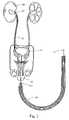
- FIG. 1is an illustration of a present technique for ureteral stent placement
- FIG. 2is an illustration of a technique for dual dilatation
- FIG. 3is a cross-sectional view of a first embodiment of a kit according to the present invention.
- FIGS. 3 a and 3 bdepict a catheter and a sheath useful in kit embodiments
- FIG. 4depicts a pigtail ureteral stent
- FIGS. 5 , 5 a and 5 bdepict a ureteral stent useful in kit embodiments
- FIG. 5 cdepicts a second embodiment of a stent
- FIG. 6depicts a stricture in a body lumen.
- FIGS. 1 and 2illustrate the differences in technique between a present method for ureteral stent placement and a new method of coaxial dual dilatation.
- a physiciandesires to perform a procedure upon a kidney 10 .
- a guidewire 14is advanced through a urethra 13 , a bladder 12 , and a ureter 11 to the kidney on which the procedure is to be performed.
- the wire guideis placed, and a ureteral stent 15 is guided along the guidewire, extending as far as desired, typically into the kidney by means of a pushing tube 18 that is also placed along the guidewire as shown.
- the physicianplaces the stent by passing first the guidewire, and then passing the ureteral stent and the pushing tube over the guidewire.
- the urethramay be dilated separately to accommodate an instrument such as a cystoscope to aid the surgeon.
- the guidewireis typically between 0.018 to 0.038 inches in diameter (about 0.46 mm to 0.97 mm).
- the cathetermay be 4-8 Fr.
- the ureteral stentmay be used for patency of the ureteral lumen.
- a very long wire guidewas needed to extend the length of the both the catheter and the access sheath, where the access sheath is capable of extending to the ureteropelvic junction. This may lead to kinking and may also lead to difficulty in the physician controlling the wire guide as he or she must control the entire length of the wire guide while sequentially running the catheter and the access sheath down the wire guide.
- FIG. 2An improved method is illustrated in FIG. 2 .
- a physicianplaces a wire guide 17 through a urethra 13 , a bladder 12 , and a ureter 11 into a kidney 10 .
- a catheter 19 secured to an access sheath 16is guided along the wire guide, the catheter and access sheath combination coaxially “dual dilating” at least the proximal portion of the ureter.
- This coaxial dilatation procedureenables the physician to use a shorter wire guide, e.g., using a 145 or 150 cm wire guide rather than a wire guide that may have to be 220 cm or even longer, perhaps 250-260 cm.
- the access sheath and the catheterare advanced to the desired location, e.g., into the calices of a kidney.
- the cathetermay then be removed and replaced by a stent.
- the stentis then implanted by a surgeon pushing on a stent positioner, such as a catheter or other pushing device of appropriate diameter and length.
- the sheathis then retracted while the positioner or other device is used to keep the stent in place.
- a physicianmay use a nephrostomy method, in which the access sheath and catheter are advanced through a person's skin to reach the calices of the kidney directly. If a path to a bile duct is needed, the physician may access the bile duct through an endoscope via the mouth, esophagus, stomach and intestines, or via laparoscopic methods directly through the skin (percutaneous). If vascular access is desired, a physician may access the blood vessel through an opening, such as an opening manufactured in the femoral artery.
- the kitincludes a wire guide 31 , which may be shorter than a wire guide used for a sequential procedure as described above.
- a wire guide with a length of about 145-150 cmis preferred, but other lengths may be used.
- a catheter 32is included, the catheter preferably having a proximal end 32 a with a flared tip 32 b , and a soft rounded/tapered non-traumatic tip 32 c for protection of the patient.
- Materials for the catheterare typically plastic or elastomeric materials, e.g., PVC, PTFE, polyurethane, silicone, and urethane, but any medically acceptable materials may be used.
- Catheters suitable for this useare preferably about 50-85 cm long.
- the tipis flared for ease in securing to connectors and in sealing with connectors so that the catheter may deliver a fluid, such as a radiopaque fluid for diagnostic procedures or for visualization purposes.
- the cathetermay have a hydrophilic coating 32 d on at least part of its outer surface.
- the proximal portionmay also have one or more marking bands 32 e to assist the physician in deploying the stent.
- Catheter 32may interface with one or more connectors 36 for mating with syringe adapter 37 (such as a female Luer lock adapter) so that a syringe (not shown) can inject the radiopaque fluid.
- Connector 36may include a male Luer lock fitting 36 a on a distal end of connector 36 and internal threads 36 b on its proximal end.
- Male Luer lock connection 36 amay be used to connect first connector 36 to second connector 35 .
- Threads 36 bmay interface with matching external threads 37 a of syringe adapter 37 for delivery of a fluid through lumen 37 b .
- Flared end 32 b of the catheterhelps to seal the connection between connector 36 , catheter 32 , and syringe 37 .
- Luer lock and threaded connections depicted and describedare preferred, other connectors may be used instead.
- quick-release connectorscould be used to secure the catheter or sheath to their proximal fittings.
- Access sheath 33includes a proximal portion 33 a and an end portion with a flared tip 33 b .
- the access sheathalso includes a distal end 33 c , preferably atraumatic, soft and rounded or tapered for ease of introduction into the patient.
- Distal end 33 c of the access sheathis also preferably more highly radiopaque than the remainder of the access sheath, so that the end may be observed with x-ray or fluoroscopic detection means during the implantation procedure.
- Flared tip 33 bhelps to seal an interface between access sheath 32 and connector 34 .
- Access sheathsare preferably are made from low friction polymers (e.g.
- PTFE, FEP etc.with reasonable radial compressive strength—wire reinforcement can be added to the sheath for extra radial strength.
- Suitable access sheaths sold under the name of Check-Flo® II Introducer sheaths sold by Cook Incorporated, Ind.may be used.
- Flexor® sheaths available from Cook Urological Incorporated of Spencer, Ind.may be used. In this application the sheath is typically 70 cm long so to extend from the urethral meatus to the ureteropelvic junction.
- the access sheathis generally just slightly larger in inner diameter than the outer diameter of the catheter, e.g. 0.5 Fr. If catheter 32 , as shown in FIG.
- the cathetermay be used as a stent positioner, with the physician simply butting the distal end of the catheter against the proximal end of the stent so that the positioner can be used to push the stent into position.
- Connector 34may include internal threads 34 a for connecting to Luer lock connector 35 having female Luer lock connection 35 b . While Luer lock connections and connectors are preferred, other connectors and other types of medically-acceptable connectors may be used. At least a distal portion of sheath 33 may also include a hydrophilic coating 38 .
- connection 34may be temporarily joined to connector 35 with an adhesive.
- Other methodsmay also be used, such as securely tightening connectors 34 , 35 together.
- Joining the female Luer lock connection 35 b to male Luer lock connection 36 areliably secures access sheath 32 to catheter 33 for insertion or for removal.
- catheter 32By breaking the connection between connectors 35 , 36 after insertion, catheter 32 may be removed and the access sheath may be used for other purposes. These other purposes may include diagnostic purposes, such as insertion of an endoscope, or therapeutic procedures, such as breaking up stones or calculi, using a holmium laser or other type of lithotripter.
- a grasper or basketmay then be inserted into the working channel of the endoscope to remove the fragments.
- connectors 36 , 37may also be temporarily joined with an adhesive to prevent easily breaking the connection. By adhering connector pairs 34 , 35 and 36 , 37 , it is easier for the surgeon to make and break the Luer lock connection between connectors 35 , 36 .
- the cathetermay be longer than the access sheath, and may extend slightly further distally than the access sheath. Nevertheless, the sheath and the catheter are substantially coaxial, i.e., catheter 32 runs the entire length of access sheath 33 . Substantially coaxial means that substantially the length of one of the sheath and the catheter is coaxial with the other of the sheath and the catheter during the procedure for implanting a stent or other device into a human or mammalian body.
- the access sheathmay also be used to place a ureteral stent when the above diagnostic or therapeutic procedures are completed. No matter how gentle the procedures described above, there is a chance of some amount of trauma to the ureter during the procedures. Accordingly, it may be prudent to place a stent into the ureter to maintain patency of the ureteral lumen.
- Ureteral stentsmay be of the “double pigtail” variety, such as those available from Cook Urological Incorporated, Spencer, Ind.
- FIG. 4depicts one such stent 40 .
- These ureteral stentsare typically available in sizes of 4 Fr to 8 Fr and may be placed into a ureter using a wire guide and the procedure described above.
- FIG. 6depicts one such case.
- ureter 70is constrained from its normal width 73 into a narrower path 71 along part of its length by a constricting body mass 72 .
- An examplewould be a cancerous growth near the ureter that would cause compression on the ureter, e.g., colon cancer, bladder cancer, ovarian cancer, endometrial cancer, cervical cancer, and the like.
- a stent with greater radial strengthmay be needed in order to maintain its lumen and allow drainage of urine through the ureter.
- a stent made from material that is more resistant to deformationmay be needed.
- the stentmust be removable without significant deformation or resistance.
- Stent 50is made from coiled wire along its length 51 and at both distal and proximal ends 52 , 53 , which may be substantially the same or may be different.
- the coilsshould be closely spaced so that they touch, but still allow fluid, such as urine or bile, to flow through the coils.
- the coilsshould also be spaced closely enough so that no tissue ingrowth occurs.
- Materials used in these stentsare preferably biocompatible and corrosion-resistant.
- the wireis preferably made from alloys with minimal or low magnetic properties to avoid interference with diagnostic equipment, such as MRI machines. Alloys such as MP35N, MP 159, Astroloy M, Inconel 625, 316 stainless steel, 35N LT, Biodur 108, pure titanium, and Hastelloy S are preferred.
- An inner wire 57extends throughout the length of the stent and is secured to both ends 52 , 53 , such as by welding, brazing or swaging to a tip 54 on each end.
- the tips and the wireare preferably made from the same metallic alloy as the coil.
- the tipsmay be formed into a molten domed mass from the coiled wire and the inner wire during the joining process. It is important that both ends be atraumatic to the patient.
- the coils 55have small gaps 56 between them so that urine may soak or leak into the stent in the kidney area or anywhere along the ureter and may leak out of the coils in the ureter or bladder area.
- the internal wireis helpful in preventing unraveling or extension of the coils, especially when the stent is being removed.
- the portion of the stent between the pigtailsis preferably about 20 cm to about 32 cm long. Other lengths may be used.
- stent embodimentsshould be highly polished, preferably electro-polished.
- electro-polishingthe article to be polished is placed into an electrolytic bath, but instead of being plated, the current is reversed. Asperities, tiny projections of metal on the surface of the stent coils, are vulnerable to this process, and are removed without changing the dimensions or temper of the stent.
- This highly polished surfaceis believed to be resistant to the bacteria responsible for encrustation because there are fewer sites of surface roughness suitable for adherence.
- the wire 55 used for the outer coilsis preferably coated, such as with a fluoropolymer or other protective, lubricious coating 58 before it is wound into a coil. It is preferred that the entire coil length be coated, while preserving the small gaps between the coil-turns of the stent for functioning of the stent drainage mechanism.
- a layer 59 of a preventive or other medicationmay be applied over coating 58 , such as a layer containing heparin or other drug. Heparin tends to resist encrustation with long-term implantation of urinary tract medical devices. Heparin or other drug-containing coatings are preferably applied after the coil is wound.
- Fluoropolymers such as PTFEhelp to enable the bonding of certain drugs, such as heparin, to the surface of the coils and are therefore desirable in stents intended for long-term implantation.
- Other drugs useful for discouraging encrustationinclude heparin, covalent heparin, dexamethazone, dexamethasone sodium phosphate, dexamethasone acetate and other dexamethasone derivatives, triclosan, silver nitrate, ofloxacin, ciproflaxin, phosphorylcholine and triemethoprim.
- the wire for coilingis coated, as by extrusion, with a fluoropolymer or other lubricious polymer or plastic material, and is then wound into a coiled stent, complete with end caps and a coated internal wire.
- the stentis then immersed into a solution of heparin, and a partial vacuum is applied to the vessel containing the solution.
- a vacuum10 Torr or less for a time period of about one minute to one hour, depending on the amount of coating desired.
- the stentsare then rinsed in distilled water and dried before being packaged.
- FIG. 5 cAnother embodiment of a stent with greater radial strength is depicted in FIG. 5 c .
- a narrow hollow cannula 64extends between the distal and proximal ends of the stent 60 .
- Stent 60includes metallic ends 61 which include an orifice 63 to accommodate cannula 64 .
- the stentincludes a hollow outer coil 62 for greater radial strength.
- Cannula lumen 65may be used to enable placement by a wire guide, and also may act as a lumen for drainage of body fluids, such as urine or bile.
- Fluid connector 66may be attached to a proximal end of the cannula for connection for fluid drainage or for infusion of diagnostic or therapeutic fluids.
- the fluid connectormay be attached by threads, by soldering or brazing, by or by any convenient method.
- one or more additional medications or drugsmay be placed on the surface of the stent in order to assist in patient care and comfort.
- an antimicrobial drugsuch as a combination of rifampin and minocycline, may help to reduce inflammation and microbial activity in the vicinity of the stent.
- Antimicrobial coatings applied to the stentmay include the following drugs, or their salts or derivatives: rifampin, minocycline, a mixture of rifampin and minocycline, a non-steroidal anti-inflammatory agent, a penicillin, a cephalosporin, a carbepenem, a beta-lactam, an antibiotic, an aminoglycoside, a macrolide, a lincosamide, a glycopeptide, a tetracyline, a chloramphenicol, a quinolone, a fucidin, a sulfonamide, a trimethoprim, a rifamycin, an oxaline, a streptogramin, a lipopeptide, a ketolide, a polyene, an azole, an echinocandin, alpha-terpineol, methylisothiazolone, cetylpyridinium chloride, chloroxyleneo
- antimicrobialsare anthracyclines, such as doxorubicin or mitoxantrone, fluoropyrimidines such as 5-fluoroacil, and also podophylotoxins, such as etoposide.
- anthracyclinessuch as doxorubicin or mitoxantrone
- fluoropyrimidinessuch as 5-fluoroacil
- podophylotoxinssuch as etoposide.
- the salts and the derivatives of all of theseare meant to be included as examples of antimicrobial drugs.
- Analgesicssuch as aspirin or other non-steroidal anti-inflammatory drugs, may also be applied to the surface to reduce pain and swelling upon implantation of the stent.
- These drugs or their salts or derivativesmay include aspirin and non-steroidal anti-inflammatory drugs, including naproxen, choline, diflunisal, salsalate, fenoprofen, flurbiprofen, ketoprofen, ibuprofen, oxaprozin, diclofenac, indomethacin, sulindac, acetoaminophen, tolmetin, meloxicam, piroxicam, meclofenamate, mefanimic acid, nabumetone, etodelac, keterolac, celecoxib, valdecoxib and rofecoxib, mixtures thereof, and derivatives thereof.
- analgesics or anestheticsthat may be coated onto the surface of the stent include opioids, synthetic drugs with narcotic properties, and local anesthetics to include at least paracetamol, bupivacaine, ropivacaine, lidocaine, and novacaine.alfentanil, buprenorphine, carfentanil, codeine, codeinone, dextropropoxyphene, dihydrocodeine, endorphin, fentanyl, hydrocodone, hydromorphone, methadone, morphine, morphinone, oxycodone, oxymorphone, pethidine, remifantanil, sulfentanil, thebaine, and tramadol, mixtures thereof, and derivatives thereof.
- any of these drugs and coatingsare preferably applied in a time-release manner so that the beneficial effect of the drug is sustained over a period of at least several weeks or months. This may be especially helpful in the case where a stent or catheter will remain in place for a considerable length of time.
- While the present stentis highly useful for drainage of the kidneys, similar stents may be used in other hollow parts of the body. These may include procedures, hepatic drainage, gastro-intestinal drainage, and so on, for drainage of other body cavities. It is intended that the foregoing detailed description be regarded as illustrative rather than limiting, and that it be understood that it is the following claims, including all equivalents, that are intended to define the spirit and scope of this invention.
Landscapes
- Health & Medical Sciences (AREA)
- Urology & Nephrology (AREA)
- Ophthalmology & Optometry (AREA)
- Otolaryngology (AREA)
- Engineering & Computer Science (AREA)
- Anesthesiology (AREA)
- Biomedical Technology (AREA)
- Heart & Thoracic Surgery (AREA)
- Hematology (AREA)
- Life Sciences & Earth Sciences (AREA)
- Animal Behavior & Ethology (AREA)
- General Health & Medical Sciences (AREA)
- Public Health (AREA)
- Veterinary Medicine (AREA)
- Media Introduction/Drainage Providing Device (AREA)
- Prostheses (AREA)
Abstract
Description
Claims (19)
Priority Applications (9)
| Application Number | Priority Date | Filing Date | Title |
|---|---|---|---|
| US11/218,210US7550012B2 (en) | 2005-08-31 | 2005-08-31 | Stent for implantation |
| AT06802662TATE514448T1 (en) | 2005-08-31 | 2006-08-30 | CATHETER FOR IMPLANTATION OF STENTS |
| EP06802662AEP1942971B1 (en) | 2005-08-31 | 2006-08-30 | Catheter for implantation of Stents |
| DK06802662.4TDK1942971T3 (en) | 2005-08-31 | 2006-08-30 | Catheter for implantation of stents |
| AU2006284819AAU2006284819B2 (en) | 2005-08-31 | 2006-08-30 | Coaxial dilatation method for stent implantation |
| CA2621223ACA2621223C (en) | 2005-08-31 | 2006-08-30 | Coaxial dilatation method for stent implantation |
| JP2008529254AJP5226515B2 (en) | 2005-08-31 | 2006-08-30 | Access kit |
| PCT/US2006/033944WO2007027830A1 (en) | 2005-08-31 | 2006-08-30 | Coaxial dilatation method for stent implantation |
| US11/748,323US7789915B2 (en) | 2005-08-31 | 2007-05-14 | Stent for implantation |
Applications Claiming Priority (1)
| Application Number | Priority Date | Filing Date | Title |
|---|---|---|---|
| US11/218,210US7550012B2 (en) | 2005-08-31 | 2005-08-31 | Stent for implantation |
Related Parent Applications (1)
| Application Number | Title | Priority Date | Filing Date |
|---|---|---|---|
| US11/513,445Continuation-In-PartUS20070050006A1 (en) | 2005-08-31 | 2006-08-30 | Coaxial dilatation method for stent implantation |
Related Child Applications (1)
| Application Number | Title | Priority Date | Filing Date |
|---|---|---|---|
| US11/748,323Continuation-In-PartUS7789915B2 (en) | 2005-08-31 | 2007-05-14 | Stent for implantation |
Publications (2)
| Publication Number | Publication Date |
|---|---|
| US20070078446A1 US20070078446A1 (en) | 2007-04-05 |
| US7550012B2true US7550012B2 (en) | 2009-06-23 |
Family
ID=37902815
Family Applications (1)
| Application Number | Title | Priority Date | Filing Date |
|---|---|---|---|
| US11/218,210Active2027-06-05US7550012B2 (en) | 2005-08-31 | 2005-08-31 | Stent for implantation |
Country Status (1)
| Country | Link |
|---|---|
| US (1) | US7550012B2 (en) |
Cited By (14)
| Publication number | Priority date | Publication date | Assignee | Title |
|---|---|---|---|---|
| US20080108824A1 (en)* | 2006-09-28 | 2008-05-08 | Med Institute, Inc | Medical Devices Incorporating a Bioactive and Methods of Preparing Such Devices |
| US20090030363A1 (en)* | 2002-10-30 | 2009-01-29 | Gellman Barry N | Linearly expandable ureteral stent |
| EP2745804A1 (en) | 2012-12-19 | 2014-06-25 | Cook Medical Technologies LLC | Flexible stent and delivery system |
| EP2749310A1 (en) | 2012-12-28 | 2014-07-02 | Cook Medical Technologies LLC | Ureteral endoluminal device |
| US8900620B2 (en) | 2005-10-13 | 2014-12-02 | DePuy Synthes Products, LLC | Drug-impregnated encasement |
| US20150005864A1 (en)* | 2013-06-28 | 2015-01-01 | Gadelius Medical, K. K. | Stent kit |
| US9033956B2 (en) | 2011-09-06 | 2015-05-19 | Cook Medical Technologies Llc | Electrically charged medical device |
| US9108017B2 (en) | 2011-03-22 | 2015-08-18 | Applied Medical Resources Corporation | Method of making tubing have drainage holes |
| US9254203B2 (en) | 2012-08-20 | 2016-02-09 | Boston Scientific Scimed, Inc. | Delivery device |
| US9381683B2 (en) | 2011-12-28 | 2016-07-05 | DePuy Synthes Products, Inc. | Films and methods of manufacture |
| US9763814B2 (en) | 2014-10-24 | 2017-09-19 | Cook Medical Technologies Llc | Elongate medical device |
| US9877854B2 (en) | 2014-05-21 | 2018-01-30 | Boston Scientific Scimed, Inc. | Stent delivery system |
| US10500304B2 (en) | 2013-06-21 | 2019-12-10 | DePuy Synthes Products, Inc. | Films and methods of manufacture |
| US11039914B2 (en) | 2018-10-22 | 2021-06-22 | Sevro Technologies Llc | Variable length stent |
Families Citing this family (29)
| Publication number | Priority date | Publication date | Assignee | Title |
|---|---|---|---|---|
| US7349971B2 (en)* | 2004-02-05 | 2008-03-25 | Scenera Technologies, Llc | System for transmitting data utilizing multiple communication applications simultaneously in response to user request without specifying recipient's communication information |
| US7789915B2 (en)* | 2005-08-31 | 2010-09-07 | Vance Products Incorporated | Stent for implantation |
| US20070050006A1 (en)* | 2005-08-31 | 2007-03-01 | Cook Ireland Limited | Coaxial dilatation method for stent implantation |
| US8425459B2 (en) | 2006-11-20 | 2013-04-23 | Lutonix, Inc. | Medical device rapid drug releasing coatings comprising a therapeutic agent and a contrast agent |
| US9737640B2 (en) | 2006-11-20 | 2017-08-22 | Lutonix, Inc. | Drug releasing coatings for medical devices |
| US20080276935A1 (en) | 2006-11-20 | 2008-11-13 | Lixiao Wang | Treatment of asthma and chronic obstructive pulmonary disease with anti-proliferate and anti-inflammatory drugs |
| US9700704B2 (en) | 2006-11-20 | 2017-07-11 | Lutonix, Inc. | Drug releasing coatings for balloon catheters |
| US8414910B2 (en) | 2006-11-20 | 2013-04-09 | Lutonix, Inc. | Drug releasing coatings for medical devices |
| US8414526B2 (en)* | 2006-11-20 | 2013-04-09 | Lutonix, Inc. | Medical device rapid drug releasing coatings comprising oils, fatty acids, and/or lipids |
| US8998846B2 (en) | 2006-11-20 | 2015-04-07 | Lutonix, Inc. | Drug releasing coatings for balloon catheters |
| US8414525B2 (en) | 2006-11-20 | 2013-04-09 | Lutonix, Inc. | Drug releasing coatings for medical devices |
| US20080175887A1 (en) | 2006-11-20 | 2008-07-24 | Lixiao Wang | Treatment of Asthma and Chronic Obstructive Pulmonary Disease With Anti-proliferate and Anti-inflammatory Drugs |
| JP2008305262A (en)* | 2007-06-08 | 2008-12-18 | Konica Minolta Business Technologies Inc | Printer introduction method in server and thin client environment |
| US20090105719A1 (en)* | 2007-10-19 | 2009-04-23 | Vance Products Incorporated, D/B/A Cook Urological Incorporated | Precision stent positioner |
| WO2009154834A2 (en)* | 2008-03-27 | 2009-12-23 | Boston Scientific Scimed, Inc. | Ureteral stents for release of urologically beneficial agents |
| WO2010024898A2 (en) | 2008-08-29 | 2010-03-04 | Lutonix, Inc. | Methods and apparatuses for coating balloon catheters |
| US9198968B2 (en) | 2008-09-15 | 2015-12-01 | The Spectranetics Corporation | Local delivery of water-soluble or water-insoluble therapeutic agents to the surface of body lumens |
| US8114429B2 (en) | 2008-09-15 | 2012-02-14 | Cv Ingenuity Corp. | Local delivery of water-soluble or water-insoluble therapeutic agents to the surface of body lumens |
| US9387312B2 (en) | 2008-09-15 | 2016-07-12 | Brightwater Medical, Inc. | Convertible nephroureteral catheter |
| US8257722B2 (en) | 2008-09-15 | 2012-09-04 | Cv Ingenuity Corp. | Local delivery of water-soluble or water-insoluble therapeutic agents to the surface of body lumens |
| US9956100B2 (en) | 2009-09-15 | 2018-05-01 | Brightwater Medical, Inc. | Systems and methods for coupling and decoupling a catheter |
| US10349958B2 (en)* | 2012-03-27 | 2019-07-16 | Cook Medical Technologies Llc | Lithotripsy probes and methods for performing lithotripsy |
| US9956385B2 (en)* | 2012-06-28 | 2018-05-01 | The Spectranetics Corporation | Post-processing of a medical device to control morphology and mechanical properties |
| US8956340B2 (en)* | 2012-12-13 | 2015-02-17 | University Of South Florida | Urethral catheter assembly with a guide wire |
| WO2015108609A1 (en)* | 2014-01-20 | 2015-07-23 | Brightwater Medical, Inc. | Convertible nephroureteral catheter |
| US10525171B2 (en) | 2014-01-24 | 2020-01-07 | The Spectranetics Corporation | Coatings for medical devices |
| US20180126129A1 (en)* | 2014-07-21 | 2018-05-10 | Stentorium Ltd | Implantable Stent |
| EP3936088A1 (en) | 2014-08-12 | 2022-01-12 | Merit Medical Systems, Inc. | Systems and methods for coupling and decoupling a catheter |
| US12226327B2 (en) | 2020-04-15 | 2025-02-18 | Merit Medical Systems, Inc. | Systems and methods for coupling and decoupling a catheter |
Citations (37)
| Publication number | Priority date | Publication date | Assignee | Title |
|---|---|---|---|---|
| US2264988A (en) | 1940-07-31 | 1941-12-02 | Westinghouse Electric & Mfg Co | Mounting of bimetallic elements |
| US4713049A (en) | 1986-08-05 | 1987-12-15 | Medical Engineering Corporation | Ureteral stent kit |
| US4813925A (en) | 1987-04-21 | 1989-03-21 | Medical Engineering Corporation | Spiral ureteral stent |
| US4913683A (en) | 1988-07-05 | 1990-04-03 | Medical Engineering Corporation | Infusion stent system |
| EP0365269A1 (en) | 1988-10-17 | 1990-04-25 | VANCE PRODUCTS INCORPORATED d/b/a COOK UROLOGICAL INCORPORATED | Indwelling ureteral stent placement apparatus |
| US4931037A (en) | 1988-10-13 | 1990-06-05 | International Medical, Inc. | In-dwelling ureteral stent and injection stent assembly, and method of using same |
| US4930496A (en) | 1988-07-22 | 1990-06-05 | Vance Products, Inc. | Method and device for removing a stone from a ureter using extracorporeal shock wave lithotripsy |
| US5334185A (en) | 1991-06-28 | 1994-08-02 | Giesy Consultants, Inc. | End-to-end instrument placement apparatus |
| US5441516A (en) | 1994-03-03 | 1995-08-15 | Scimed Lifesystems Inc. | Temporary stent |
| US5554189A (en) | 1994-02-25 | 1996-09-10 | De La Torre; Fernando I. | Ureteral prosthesis |
| US5582619A (en) | 1995-06-30 | 1996-12-10 | Target Therapeutics, Inc. | Stretch resistant vaso-occlusive coils |
| CA2264988A1 (en) | 1998-03-10 | 1999-09-10 | Cordis Corporation | Embolic coil deployment system with improved embolic coil |
| US6033413A (en) | 1998-04-20 | 2000-03-07 | Endocare, Inc. | Stent delivery system |
| US6264611B1 (en)* | 1998-11-25 | 2001-07-24 | Ball Semiconductor, Inc. | Monitor for interventional procedures |
| US20010018574A1 (en) | 1997-08-14 | 2001-08-30 | Scimed Life Systems, Inc. | Drainage catheter delivery system |
| US6332892B1 (en)* | 1999-03-02 | 2001-12-25 | Scimed Life Systems, Inc. | Medical device with one or more helical coils |
| US20020183852A1 (en) | 2001-06-01 | 2002-12-05 | Mcweeney John O. | Compressible ureteral stent for comfort |
| US6589262B1 (en) | 2000-03-31 | 2003-07-08 | Medamicus, Inc. | Locking catheter introducing system |
| WO2003079930A1 (en) | 2002-03-18 | 2003-10-02 | Scimed Life Systems, Inc. | Expandable ureteral stent |
| US6652536B2 (en)* | 2000-09-29 | 2003-11-25 | Primus Medical, Inc. | Snare with anti-skewing |
| US20040078088A1 (en) | 2002-10-22 | 2004-04-22 | Scimed Life Systems | Male urethral stent device |
| US20040087886A1 (en)* | 2002-10-30 | 2004-05-06 | Scimed Life Systems, Inc. | Linearly expandable ureteral stent |
| US6736839B2 (en) | 2001-02-01 | 2004-05-18 | Charles Cummings | Medical device delivery system |
| US6746489B2 (en) | 1998-08-31 | 2004-06-08 | Wilson-Cook Medical Incorporated | Prosthesis having a sleeve valve |
| US20040127918A1 (en) | 1995-06-07 | 2004-07-01 | Conceptus, Inc. | Contraceptive transcervical fallopian tube occlusion devices and methods |
| US6770101B2 (en) | 2001-10-09 | 2004-08-03 | Scimed Life Systems, Inc. | Prostatic stent and delivery system |
| US20040181186A1 (en) | 2003-03-13 | 2004-09-16 | Scimed Life Systems, Inc. | Medical device |
| US20050234388A1 (en)* | 2004-03-23 | 2005-10-20 | Ray Amos | Agent eluting stent and catheter |
| US20050240278A1 (en)* | 2004-04-26 | 2005-10-27 | Peter Aliski | Stent improvements |
| US7044981B2 (en)* | 2003-01-22 | 2006-05-16 | Boston Scientific Scimed, Inc. | Ureteral stent configured for improved patient comfort and aftercare |
| US20070021840A1 (en) | 2005-07-20 | 2007-01-25 | Jorge Lopera | Temporal stricture expander |
| US20070078511A1 (en) | 2005-09-30 | 2007-04-05 | Boston Scientific Scimed, Inc. | Hybrid bifurcated stent |
| US20070276466A1 (en)* | 2005-08-31 | 2007-11-29 | Vance Products Inc., D/B/A/ Cook Urological Inc. | Stent for implantation |
| US20080086215A1 (en)* | 2001-04-02 | 2008-04-10 | St Pierre Ernest J | Medical Stent and Related Methods |
| US20080133025A1 (en)* | 2003-03-10 | 2008-06-05 | Daignault Kenneth J | Medical stent |
| US20080183299A1 (en)* | 2005-06-21 | 2008-07-31 | Vance Products Inc., D/B/A/ Cook Urological Inc. | Ureteral stent with axial and radial variability |
| US20080208083A1 (en)* | 2006-04-28 | 2008-08-28 | Bryant Lin | System and method to counter material deposition on devices in the urinary tract |
Family Cites Families (8)
| Publication number | Priority date | Publication date | Assignee | Title |
|---|---|---|---|---|
| US127918A (en)* | 1872-06-11 | Improvement in tail-nets for horses | ||
| US878511A (en)* | 1907-07-29 | 1908-02-11 | Us Fastener Company | Fastener. |
| US5690666A (en)* | 1992-11-18 | 1997-11-25 | Target Therapeutics, Inc. | Ultrasoft embolism coils and process for using them |
| ATE295127T1 (en)* | 1994-03-03 | 2005-05-15 | Boston Scient Ltd | DEVICE FOR DETECTING THE DIVISION OF A VASS OCCLUSION DEVICE |
| US6096034A (en)* | 1996-07-26 | 2000-08-01 | Target Therapeutics, Inc. | Aneurysm closure device assembly |
| US6395021B1 (en)* | 1997-02-26 | 2002-05-28 | Applied Medical Resources Corporation | Ureteral stent system apparatus and method |
| US6280457B1 (en)* | 1999-06-04 | 2001-08-28 | Scimed Life Systems, Inc. | Polymer covered vaso-occlusive devices and methods of producing such devices |
| US6921390B2 (en)* | 2001-07-23 | 2005-07-26 | Boston Scientific Scimed, Inc. | Long-term indwelling medical devices containing slow-releasing antimicrobial agents and having a surfactant surface |
- 2005
- 2005-08-31USUS11/218,210patent/US7550012B2/enactiveActive
Patent Citations (42)
| Publication number | Priority date | Publication date | Assignee | Title |
|---|---|---|---|---|
| US2264988A (en) | 1940-07-31 | 1941-12-02 | Westinghouse Electric & Mfg Co | Mounting of bimetallic elements |
| US4713049A (en) | 1986-08-05 | 1987-12-15 | Medical Engineering Corporation | Ureteral stent kit |
| US4813925A (en) | 1987-04-21 | 1989-03-21 | Medical Engineering Corporation | Spiral ureteral stent |
| US4913683A (en) | 1988-07-05 | 1990-04-03 | Medical Engineering Corporation | Infusion stent system |
| US4930496A (en) | 1988-07-22 | 1990-06-05 | Vance Products, Inc. | Method and device for removing a stone from a ureter using extracorporeal shock wave lithotripsy |
| US4931037A (en) | 1988-10-13 | 1990-06-05 | International Medical, Inc. | In-dwelling ureteral stent and injection stent assembly, and method of using same |
| EP0365269A1 (en) | 1988-10-17 | 1990-04-25 | VANCE PRODUCTS INCORPORATED d/b/a COOK UROLOGICAL INCORPORATED | Indwelling ureteral stent placement apparatus |
| US4957479A (en) | 1988-10-17 | 1990-09-18 | Vance Products Incorporated | Indwelling ureteral stent placement apparatus |
| EP0365269B1 (en) | 1988-10-17 | 1994-03-16 | VANCE PRODUCTS INCORPORATED d/b/a COOK UROLOGICAL INCORPORATED | Indwelling ureteral stent placement apparatus |
| US5334185A (en) | 1991-06-28 | 1994-08-02 | Giesy Consultants, Inc. | End-to-end instrument placement apparatus |
| US5554189A (en) | 1994-02-25 | 1996-09-10 | De La Torre; Fernando I. | Ureteral prosthesis |
| US5441516A (en) | 1994-03-03 | 1995-08-15 | Scimed Lifesystems Inc. | Temporary stent |
| US20040127918A1 (en) | 1995-06-07 | 2004-07-01 | Conceptus, Inc. | Contraceptive transcervical fallopian tube occlusion devices and methods |
| US5582619A (en) | 1995-06-30 | 1996-12-10 | Target Therapeutics, Inc. | Stretch resistant vaso-occlusive coils |
| US20010018574A1 (en) | 1997-08-14 | 2001-08-30 | Scimed Life Systems, Inc. | Drainage catheter delivery system |
| CA2264988A1 (en) | 1998-03-10 | 1999-09-10 | Cordis Corporation | Embolic coil deployment system with improved embolic coil |
| US6033413A (en) | 1998-04-20 | 2000-03-07 | Endocare, Inc. | Stent delivery system |
| US6746489B2 (en) | 1998-08-31 | 2004-06-08 | Wilson-Cook Medical Incorporated | Prosthesis having a sleeve valve |
| US6264611B1 (en)* | 1998-11-25 | 2001-07-24 | Ball Semiconductor, Inc. | Monitor for interventional procedures |
| US6332892B1 (en)* | 1999-03-02 | 2001-12-25 | Scimed Life Systems, Inc. | Medical device with one or more helical coils |
| US6589262B1 (en) | 2000-03-31 | 2003-07-08 | Medamicus, Inc. | Locking catheter introducing system |
| US6652536B2 (en)* | 2000-09-29 | 2003-11-25 | Primus Medical, Inc. | Snare with anti-skewing |
| US6736839B2 (en) | 2001-02-01 | 2004-05-18 | Charles Cummings | Medical device delivery system |
| US20080086215A1 (en)* | 2001-04-02 | 2008-04-10 | St Pierre Ernest J | Medical Stent and Related Methods |
| US6887215B2 (en) | 2001-06-01 | 2005-05-03 | Boston Scientific Scimed, Inc. | Compressible ureteral stent for comfort |
| US20020183852A1 (en) | 2001-06-01 | 2002-12-05 | Mcweeney John O. | Compressible ureteral stent for comfort |
| US6770101B2 (en) | 2001-10-09 | 2004-08-03 | Scimed Life Systems, Inc. | Prostatic stent and delivery system |
| WO2003079930A1 (en) | 2002-03-18 | 2003-10-02 | Scimed Life Systems, Inc. | Expandable ureteral stent |
| US6685744B2 (en) | 2002-03-18 | 2004-02-03 | Scimed Life Systems, Inc. | Expandable ureteral stent |
| US6733536B1 (en)* | 2002-10-22 | 2004-05-11 | Scimed Life Systems | Male urethral stent device |
| US20040078088A1 (en) | 2002-10-22 | 2004-04-22 | Scimed Life Systems | Male urethral stent device |
| US20040087886A1 (en)* | 2002-10-30 | 2004-05-06 | Scimed Life Systems, Inc. | Linearly expandable ureteral stent |
| US7044981B2 (en)* | 2003-01-22 | 2006-05-16 | Boston Scientific Scimed, Inc. | Ureteral stent configured for improved patient comfort and aftercare |
| US20080133025A1 (en)* | 2003-03-10 | 2008-06-05 | Daignault Kenneth J | Medical stent |
| US20040181186A1 (en) | 2003-03-13 | 2004-09-16 | Scimed Life Systems, Inc. | Medical device |
| US20050234388A1 (en)* | 2004-03-23 | 2005-10-20 | Ray Amos | Agent eluting stent and catheter |
| US20050240278A1 (en)* | 2004-04-26 | 2005-10-27 | Peter Aliski | Stent improvements |
| US20080183299A1 (en)* | 2005-06-21 | 2008-07-31 | Vance Products Inc., D/B/A/ Cook Urological Inc. | Ureteral stent with axial and radial variability |
| US20070021840A1 (en) | 2005-07-20 | 2007-01-25 | Jorge Lopera | Temporal stricture expander |
| US20070276466A1 (en)* | 2005-08-31 | 2007-11-29 | Vance Products Inc., D/B/A/ Cook Urological Inc. | Stent for implantation |
| US20070078511A1 (en) | 2005-09-30 | 2007-04-05 | Boston Scientific Scimed, Inc. | Hybrid bifurcated stent |
| US20080208083A1 (en)* | 2006-04-28 | 2008-08-28 | Bryant Lin | System and method to counter material deposition on devices in the urinary tract |
Non-Patent Citations (5)
| Title |
|---|
| Canadian Intellectual Property Office Examiner's Report dated Aug. 20, 2007 (4 pages). |
| International Preliminary Examination Report dated Mar. 13, 2008 for related PCT application PCT/US2006/33944. |
| International Search Report from PCT application No. PCT/US2006/033944 dated Jan. 12, 2007 (4 pages). |
| Office Action dated Dec. 26, 2008 for U.S. Appl. No. 11/513,445. |
| Office Action dated Jan. 22, 2009 for related U.S. Appl. No. 11/748,323. |
Cited By (27)
| Publication number | Priority date | Publication date | Assignee | Title |
|---|---|---|---|---|
| US9060888B2 (en) | 2002-10-30 | 2015-06-23 | Boston Scientific Scimed, Inc. | Method of disposing a linearly expandable ureteral stent within a patient |
| US10201441B2 (en) | 2002-10-30 | 2019-02-12 | Boston Scientific Scimed, Inc. | Linearly expandable ureteral stent |
| US20100072659A1 (en)* | 2002-10-30 | 2010-03-25 | Gellman Barry N | Methods of Manufacturing Linearly Expandable Ureteral Stents |
| US20100076574A1 (en)* | 2002-10-30 | 2010-03-25 | Gellman Barry N | Linearly Expandable Ureteral Stent |
| US8007702B2 (en) | 2002-10-30 | 2011-08-30 | Boston Scientific Scimed, Inc. | Methods of manufacturing linearly expandable ureteral stents |
| US8241548B2 (en) | 2002-10-30 | 2012-08-14 | Boston Scientific Scimed, Inc. | Methods of manufacturing linearly expandable ureteral stents |
| US8568643B2 (en) | 2002-10-30 | 2013-10-29 | Boston Scientific Scimed, Inc. | Methods of manufacturing linearly expandable ureteral stents |
| US20090030363A1 (en)* | 2002-10-30 | 2009-01-29 | Gellman Barry N | Linearly expandable ureteral stent |
| US8900620B2 (en) | 2005-10-13 | 2014-12-02 | DePuy Synthes Products, LLC | Drug-impregnated encasement |
| US10814112B2 (en) | 2005-10-13 | 2020-10-27 | DePuy Synthes Products, Inc. | Drug-impregnated encasement |
| US9579260B2 (en) | 2005-10-13 | 2017-02-28 | DePuy Synthes Products, Inc. | Drug-impregnated encasement |
| US20080108824A1 (en)* | 2006-09-28 | 2008-05-08 | Med Institute, Inc | Medical Devices Incorporating a Bioactive and Methods of Preparing Such Devices |
| US9108017B2 (en) | 2011-03-22 | 2015-08-18 | Applied Medical Resources Corporation | Method of making tubing have drainage holes |
| US9033956B2 (en) | 2011-09-06 | 2015-05-19 | Cook Medical Technologies Llc | Electrically charged medical device |
| US9381102B2 (en) | 2011-09-06 | 2016-07-05 | Cook Medical Technologies Llc | Electrically charged medical device |
| US10617653B2 (en) | 2011-12-28 | 2020-04-14 | DePuy Synthes Products, Inc. | Films and methods of manufacture |
| US9381683B2 (en) | 2011-12-28 | 2016-07-05 | DePuy Synthes Products, Inc. | Films and methods of manufacture |
| US9254203B2 (en) | 2012-08-20 | 2016-02-09 | Boston Scientific Scimed, Inc. | Delivery device |
| EP2745804A1 (en) | 2012-12-19 | 2014-06-25 | Cook Medical Technologies LLC | Flexible stent and delivery system |
| EP2749310A1 (en) | 2012-12-28 | 2014-07-02 | Cook Medical Technologies LLC | Ureteral endoluminal device |
| US10500304B2 (en) | 2013-06-21 | 2019-12-10 | DePuy Synthes Products, Inc. | Films and methods of manufacture |
| US9844652B2 (en)* | 2013-06-28 | 2017-12-19 | Gadelius Medical, K.K. | Stent kit |
| US20150005864A1 (en)* | 2013-06-28 | 2015-01-01 | Gadelius Medical, K. K. | Stent kit |
| US9877854B2 (en) | 2014-05-21 | 2018-01-30 | Boston Scientific Scimed, Inc. | Stent delivery system |
| US9763814B2 (en) | 2014-10-24 | 2017-09-19 | Cook Medical Technologies Llc | Elongate medical device |
| US11039914B2 (en) | 2018-10-22 | 2021-06-22 | Sevro Technologies Llc | Variable length stent |
| US12350140B2 (en) | 2018-10-22 | 2025-07-08 | Sevro Technologies Llc | Variable length stent |
Also Published As
| Publication number | Publication date |
|---|---|
| US20070078446A1 (en) | 2007-04-05 |
Similar Documents
| Publication | Publication Date | Title |
|---|---|---|
| US7550012B2 (en) | Stent for implantation | |
| CA2621223C (en) | Coaxial dilatation method for stent implantation | |
| US7789915B2 (en) | Stent for implantation | |
| US20070050006A1 (en) | Coaxial dilatation method for stent implantation | |
| JP7743402B2 (en) | Device for the treatment of benign prostatic hyperplasia and associated lower urinary tract symptoms - Patent Application 20070122997 | |
| US9539127B2 (en) | Ureteral endoluminal abrasion device | |
| EP3045201B1 (en) | Ureteral stent with sideports | |
| US8747428B2 (en) | Carotid sheath with entry and tracking rapid exchange dilators and method of use | |
| US20090105719A1 (en) | Precision stent positioner | |
| EP2609892B1 (en) | Ureteral stent | |
| EP2633828B1 (en) | Introducer assembly | |
| US20070161967A1 (en) | Implantable medical device with pharmacologically active ingredient | |
| US8328760B2 (en) | Occlusion resistant catheter | |
| CN103209730A (en) | Catheter cannula with anchoring elements, catheter including thereof, and/or catheterization method using thereof | |
| CA2517702C (en) | Stent for implantation | |
| TW202400089A (en) | Systems and methods for the endovascular treatment of hydrocephalus and elevated intracranial pressure |
Legal Events
| Date | Code | Title | Description |
|---|---|---|---|
| AS | Assignment | Owner name:COOK INCORPORATED, INDIANA Free format text:ASSIGNMENT OF ASSIGNORS INTEREST;ASSIGNOR:LAVELLE, SHAY;REEL/FRAME:016951/0604 Effective date:20050829 Owner name:COOK IRELAND LIMITED, IRELAND Free format text:ASSIGNMENT OF ASSIGNORS INTEREST;ASSIGNOR:LAVELLE, SHAY;REEL/FRAME:016951/0604 Effective date:20050829 | |
| AS | Assignment | Owner name:VANCE PRODUCTS INCORPORATED, D/B/A COOK UROLOGICAL Free format text:ASSIGNMENT OF ASSIGNORS INTEREST;ASSIGNOR:COOK INCORPORATED;REEL/FRAME:019499/0259 Effective date:20070514 | |
| STCF | Information on status: patent grant | Free format text:PATENTED CASE | |
| AS | Assignment | Owner name:COOK MEDICAL TECHNOLOGIES LLC, INDIANA Free format text:ASSIGNMENT OF ASSIGNORS INTEREST;ASSIGNOR:COOK IRELAND, LTD.;REEL/FRAME:026232/0876 Effective date:20110316 | |
| AS | Assignment | Owner name:COOK MEDICAL TECHNOLOGIES LLC, INDIANA Free format text:ASSIGNMENT OF ASSIGNORS INTEREST;ASSIGNORS:COOK INCORPORATED;WILSON-COOK MEDICAL INCORPORATED;VANCE PRODUCTS INCORPORATED;AND OTHERS;SIGNING DATES FROM 20110315 TO 20110322;REEL/FRAME:026287/0923 | |
| FPAY | Fee payment | Year of fee payment:4 | |
| FPAY | Fee payment | Year of fee payment:8 | |
| MAFP | Maintenance fee payment | Free format text:PAYMENT OF MAINTENANCE FEE, 12TH YEAR, LARGE ENTITY (ORIGINAL EVENT CODE: M1553); ENTITY STATUS OF PATENT OWNER: LARGE ENTITY Year of fee payment:12 | |
| AS | Assignment | Owner name:WILMINGTON TRUST, NATIONAL ASSOCIATION, AS COLLATERAL AGENT, DELAWARE Free format text:SECURITY INTEREST;ASSIGNOR:COOK MEDICAL TECHNOLOGIES LLC;REEL/FRAME:066700/0277 Effective date:20240227 |