US7549988B2 - Hybrid lesion formation apparatus, systems and methods - Google Patents
Hybrid lesion formation apparatus, systems and methodsDownload PDFInfo
- Publication number
- US7549988B2 US7549988B2US10/930,073US93007304AUS7549988B2US 7549988 B2US7549988 B2US 7549988B2US 93007304 AUS93007304 AUS 93007304AUS 7549988 B2US7549988 B2US 7549988B2
- Authority
- US
- United States
- Prior art keywords
- energy transmission
- clamp
- transmission device
- tissue coagulation
- probe
- Prior art date
- Legal status (The legal status is an assumption and is not a legal conclusion. Google has not performed a legal analysis and makes no representation as to the accuracy of the status listed.)
- Expired - Fee Related, expires
Links
Images


Classifications
- A—HUMAN NECESSITIES
- A61—MEDICAL OR VETERINARY SCIENCE; HYGIENE
- A61B—DIAGNOSIS; SURGERY; IDENTIFICATION
- A61B18/00—Surgical instruments, devices or methods for transferring non-mechanical forms of energy to or from the body
- A61B18/04—Surgical instruments, devices or methods for transferring non-mechanical forms of energy to or from the body by heating
- A61B18/12—Surgical instruments, devices or methods for transferring non-mechanical forms of energy to or from the body by heating by passing a current through the tissue to be heated, e.g. high-frequency current
- A61B18/14—Probes or electrodes therefor
- A61B18/148—Probes or electrodes therefor having a short, rigid shaft for accessing the inner body transcutaneously, e.g. for neurosurgery or arthroscopy
- A—HUMAN NECESSITIES
- A61—MEDICAL OR VETERINARY SCIENCE; HYGIENE
- A61B—DIAGNOSIS; SURGERY; IDENTIFICATION
- A61B18/00—Surgical instruments, devices or methods for transferring non-mechanical forms of energy to or from the body
- A61B18/04—Surgical instruments, devices or methods for transferring non-mechanical forms of energy to or from the body by heating
- A61B18/12—Surgical instruments, devices or methods for transferring non-mechanical forms of energy to or from the body by heating by passing a current through the tissue to be heated, e.g. high-frequency current
- A61B18/14—Probes or electrodes therefor
- A61B18/1442—Probes having pivoting end effectors, e.g. forceps
- A—HUMAN NECESSITIES
- A61—MEDICAL OR VETERINARY SCIENCE; HYGIENE
- A61B—DIAGNOSIS; SURGERY; IDENTIFICATION
- A61B18/00—Surgical instruments, devices or methods for transferring non-mechanical forms of energy to or from the body
- A61B2018/00053—Mechanical features of the instrument of device
- A61B2018/00107—Coatings on the energy applicator
- A61B2018/00125—Coatings on the energy applicator with nanostructure
- A—HUMAN NECESSITIES
- A61—MEDICAL OR VETERINARY SCIENCE; HYGIENE
- A61B—DIAGNOSIS; SURGERY; IDENTIFICATION
- A61B18/00—Surgical instruments, devices or methods for transferring non-mechanical forms of energy to or from the body
- A61B18/04—Surgical instruments, devices or methods for transferring non-mechanical forms of energy to or from the body by heating
- A61B18/12—Surgical instruments, devices or methods for transferring non-mechanical forms of energy to or from the body by heating by passing a current through the tissue to be heated, e.g. high-frequency current
- A61B18/14—Probes or electrodes therefor
- A61B2018/1495—Electrodes being detachable from a support structure
Definitions
- the present inventionsrelate generally to devices for performing therapeutic operations on body tissue.
- Electromagnetic radio frequency (“RF”)may, for example, be used to heat and eventually kill (i.e. “ablate”) tissue to form a lesion.
- RFElectromagnetic radio frequency
- tissue coagulationoccurs and it is the coagulation that kills the tissue.
- references to the ablation of soft tissueare necessarily references to soft tissue coagulation.
- tissue coagulationis the process of cross-linking proteins in tissue to cause the tissue to jell. In soft tissue, it is the fluid within the tissue cell membranes that jells to kill the cells, thereby killing the tissue.
- the tissue coagulation energyis typically supplied by an electrosurgical unit (“ESU”) during the therapeutic procedure. More specifically, after an electrophysiology catheter, surgical probe or clamp has been connected to the ESU, and the electrodes or other energy transmission elements on the catheter, surgical probe or clamp have been positioned adjacent to the target tissue, energy from the ESU is transmitted through the energy transmission elements to the tissue to from a lesion.
- ESUelectrosurgical unit
- the amount of power required to coagulate tissueranges from 5 to 150 W.
- Some electrophysiology proceduresrequire the use of more than one electrophysiology device.
- One example of such a procedureinvolves the formation of therapeutic lesions to the treat cardiac conditions such as atrial fibrillation.
- a clampmay be used to create a first transmural epicardial lesion around the right pulmonary vein pair and a second transmural epicardial lesion around the left pulmonary vein pair.
- a surgical probemay be used to create a linear transmural epicardial lesion between the right and left pulmonary vein pairs.
- a linear transmural lesion that extends from the lesion between the right and left pulmonary vein pairs to the left atrial appendagemay also be created.
- the present inventorshave determined that conventional lesion formation devices are susceptible to improvement. For example, the present inventors have determined that the aforementioned procedure is inconvenient because it requires the surgical staff to disconnect the clamp from the ESU and connect the surgical probe to the ESU during the procedure. The inconvenience is compounded in those instances where the ESU resets and performs a diagnostic procedure each time a device is connected thereto. The present inventors have also determined that there may be more efficient and cost effective ways, in terms of materials, manufacturing, sterilization, shipping, etc., to provide physicians with the capabilities of two separate devices, such as the aforementioned separate clamp and surgical probe.
- An apparatus in accordance with one invention hereinincludes a probe component including at least one energy transmission device and an electrical connector operably connected to the at least one energy transmission device and a clamp component including at least one energy transmission device operably connected to the probe component electrical connector.
- a lesion formation apparatus in accordance with one invention hereinincludes a tissue coagulation probe including an energy transmission device carried, a bipolar tissue coagulation device including first and second energy transmission devices, a first connector that facilitates connection of the energy transmission device on the tissue coagulation probe and the first energy transmission device on the bipolar tissue coagulation device to a power output port, and a second connector that connects the second energy transmission device on the bipolar tissue coagulation device to a power return port.
- a system in accordance with one invention hereinincludes a source of tissue coagulation energy and a lesion formation apparatus including a probe component and a clamp component.
- a method in accordance with one invention hereinincludes the step of simultaneously connecting a tissue coagulation probe and a clamp-based tissue coagulation device to the same power output port on a source of tissue coagulation energy.
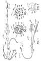
- FIG. 1is a plan view of a hybrid lesion formation apparatus in accordance with a preferred embodiment of a present invention.
- FIG. 2is a section view taken along line 2 - 2 in FIG. 1 .
- FIG. 3is a section view taken along line 3 - 3 in FIG. 1 .
- FIG. 4is an end view of the handle illustrated in FIG. 1 .
- FIG. 5is a plan view of a clamp in accordance with a preferred embodiment of a present invention.
- FIG. 6is a section view taken along line 6 - 6 in FIG. 5 .
- FIG. 7is a top view of a portion of the clamp illustrated in FIG. 5 .
- FIG. 8is a plan view of a clamp component in accordance with a preferred embodiment of a present invention.
- FIG. 9is a side, partial section view of a portion of the clamp component illustrated in FIG. 8 .
- FIG. 10is a side, partial section view of a portion of the clamp component illustrated in FIG. 8 .
- FIG. 11is a section view taken along line 11 - 11 in FIG. 9 .
- FIG. 12is a section view taken along line 12 - 12 in FIG. 10 .
- FIG. 13is a perspective view of a surgical system in accordance with a preferred embodiment of a present invention.
- FIG. 14is a plan view of a hybrid lesion formation apparatus in accordance with a preferred embodiment of a present invention.
- This specificationdiscloses a number of structures, mainly in the context of cardiac treatment, because the structures are well suited for use with myocardial tissue. Nevertheless, it should be appreciated that the structures are applicable for use in therapies involving other types of soft tissue. For example, various aspects of the present inventions have applications in procedures concerning other regions of the body such as the prostate, liver, brain, gall bladder, uterus, breasts, lungs, and other solid organs.
- a hybrid lesion formation apparatus in accordance with one embodiment of a present inventionis generally represented by reference numeral 10 in FIG. 1 .
- the exemplary embodimentincludes a surgical probe component 100 and a clamp component 200 .
- the clamp component 200 in the exemplary embodimentis adapted to be removably secured to a clamp so as to convert a conventional clamp into a electrophysiology device that may be used to form lesions in the manner discussed in greater detail below.
- the clamp componentmay include the clamp itself.
- the surgical probe component 100 and clamp component 200preferably share a common electrical connector which may be used to connect the hybrid lesion formation apparatus 10 to an electrosurgical unit (“ESU”) in the manner described below with reference to FIG. 13 .
- ESUelectrosurgical unit
- a surgical probe component 100 and a clamp component 200 in a single devicefacilitates the use of a single handle (and associated electrical connectors).
- a conventional surgical system including a surgical probe and a clampwould have two handles.
- the use of a single handle (and associated electrical connectors)allows the physician to avoid the inconveniences associated with disconnecting one device from an ESU and connecting another during a surgical procedure.
- the sterilization, packaging and shipment of the present hybrid lesion formation apparatusmay also be accomplished in a manner that is more efficient than the sterilization, packaging and shipment of separate devices.
- the surgical probe component 100 in the exemplary implementationincludes a relatively short shaft 102 , a handle 104 that is secured to the shaft, and one or more electrodes 106 or other energy transmission devices on the distal portion of the shaft.
- a strain relief element 107may also be provided.
- the shaft 102is preferably, although not necessarily, about 13 cm to 51 cm in length, and most preferably about 20 cm to 30 cm in length.
- the shaft 102is also preferably relatively stiff. In other words, the shaft 102 is rigid, malleable, or somewhat flexible. A rigid shaft cannot be bent.
- a malleable shaftis a shaft that can be readily bent by the physician to a desired shape, without springing back when released, so that it will remain in that shape during the surgical procedure.
- the stiffness of a malleable shaftmust be low enough to allow the shaft to be bent, but high enough to resist bending when the forces associated with a surgical procedure are applied to the shaft.
- a somewhat flexible shaftwill bend and spring back when released.
- the force required to bend the shaftmust be substantial.
- the shaft 102consists of a proximal portion 108 , including a malleable hypotube 110 and a non-conductive outer polymer coating 112 , and distal portion 114 , including a malleable mandrel 116 and a multi-lumen electrically non-conductive outer structure 118 .
- the proximal portion 108will typically be about 15 to 40 cm in length, while the distal portion will typically be about 6 to 15 cm in length.
- the proximal end of the malleable mandrel 116is secured to the inner surface of the distal end of the hypotube 110 by, for example, soldering, spot welding or adhesives.
- the distal end of the malleable mandrel 116is secured to a tip member 120 .
- the exemplary tip member 120is provided with a suture aperture 121 (or a suture groove). If desired, physicians may pass a suture through the aperture 121 (or around a suture groove) and use the suture to pull the shaft 102 around a body structure.
- the handle 104is configured to be gripped by the physician and used to press the shaft distal portion 114 and electrodes 106 against tissue.
- the exemplary handle 104is also about 7 to 18 cm in length and about 2 to 5 cm around its perimeter (measured perpendicularly to the longitudinal axis), which is suitable for gripping by the physician.
- the exemplary surgical probe component 100is a fluid cooled surgical probe and, as illustrated in FIG. 3 , the electrically non-conductive outer structure 118 includes fluid inlet and outlet lumens 122 and 124 , power and signal wire lumens 126 and 128 , a central lumen 130 for the mandrel 116 .
- the tip member 120includes a connection lumen (not shown) that connects the inlet lumen 122 to the outlet lumen 124 , as well as a pair of plugs (not shown) to seal the power and signal wire lumens 126 and 128 .
- Heat from the electrodes 106is transferred through the outer structure 118 to fluid that is flowing through the inlet and outlet lumens 122 and 124 .
- the material used to form the outer structure 118should be relatively high in thermal conductivity.
- “relatively high” thermal conductivityis at least about 1 W/m ⁇ K and preferably ranges from about 1 to about 10 W/m ⁇ K.
- Suitable electrically non-conductive, thermally conductive thermoplastics for the outer structure 118include flexible thermoplastic polymer materials, such as nylon or polyurethane, which are filled with a filler that promotes heat transfer. Suitable fillers include graphite, aluminum, tungsten and ceramic powders. Another suitable filler is Carborundum CarboThermTM boron nitride powder manufactured by Saint-Gobain in Cavaillon, France.
- heat transfermay be promoted by minimizing the thickness of the electrically non-conductive material between the lumens 122 and 124 and the electrodes 106 and by maximizing the cross-sectional area of the inlet and outlet lumens.
- the thickness of the outer wall 132 between the electrodes 106 and the inlet and outlet lumens 122 and 124will be about 0.08 mm to about 0.36 mm. It should be noted that when the outer wall thickness is about 0.02 mm or less, materials with less than “relatively high” thermal conductivities, such as Pebax® material and polyurethane, may also be used for the outer structure 118 .
- Suitable materials for the malleable hypotube 110include annealed stainless steel, while the suitable material for the mandrel 116 includes annealed stainless steel and beryllium copper.
- fluidmay be supplied to the surgical probe component 100 by way of an infusion tube 134 , which is connected to the inlet lumen 122 .
- the infusion tube 134extends through an aperture 135 in the handle 104 and is provided with stop-cock, which may be connected to a fluid supply and control apparatus 300 in the manner described below with reference to FIG. 13 .
- a ventilation tube 136is connected to the outlet lumen 124 and extends through an aperture 137 in the handle 104 .
- the ventilation tube 136also includes a stopcock that may be connected to the fluid supply and control apparatus.
- the electrodes 106 in the exemplary probe component 100 illustrated in FIGS. 1-4are electrically coupled to individual power wires 138 that pass from the power wire lumen 126 , and through a power wire tube 140 , to an electrical connector 141 that is associated with a slot 142 in the handle 104 .
- Suitable electrical connectorsinclude PC boards, edge card connectors, subminiature D connectors, ribbon cable connectors, and pin and socket connectors.
- a plurality of temperature sensors 144such as thermocouples or thermistors, may be located on, under, abutting the longitudinal end edges of, or in between, the electrodes 106 .
- a reference thermocouple(not shown) may also be provided.
- temperature sensors 144are located at both longitudinal ends of each electrode 106 .
- the temperature sensors 144are connected to the electrical connector 141 by signal wires 146 , which pass through the signal wire lumen 128 and a signal wire tube 148 .
- the temperature sensors 144are also located within a linear channel 150 that is formed in the non-conductive outer structure 118 .
- the linear channel 150insures that the temperature sensors will all face in the same direction (e.g. facing tissue) and be arranged in linear fashion.
- the number of electrodes carried on the shaft distal portion 114will typically depend upon the number of power connections available on the ESU and common electrical connector 141 (e.g. a PC board) as well as the number and purpose of the electrodes carried by the clamp component 200 .
- the clamp component 200includes two electrodes that are used to transmit energy and one that is used to return energy when operating in a bipolar mode, as is discussed below with reference to FIGS. 8-12 .
- the probe component 100will include five spaced electrodes 106 .
- the spaced electrodes 106are preferably in the form of wound, spiral closed coils.
- the coilsare made of electrically conducting material, like copper alloy, platinum, or stainless steel, or compositions such as drawn-filled tubing (e.g. a copper core with a platinum jacket).
- the electrically conducting material of the coilscan be further coated with platinum-iridium or gold to improve its conduction properties and biocompatibility.
- Preferred coil electrodesare disclosed in U.S. Pat. Nos. 5,797,905 and 6,245,068.
- the electrodes 106may be in the form of solid rings of conductive material, like platinum, or can comprise a conductive material, like platinum-iridium or gold, coated upon the device using conventional coating techniques or an ion beam assisted deposition (IBAD) process. For better adherence, an undercoating of nickel, silver or titanium can be applied.
- the electrodescan also be in the form of helical ribbons.
- the electrodescan also be formed with a conductive ink compound that is pad printed onto a non-conductive tubular body.
- a preferred conductive ink compoundis a silver-based flexible adhesive conductive ink (polyurethane binder), however other metal-based adhesive conductive inks such as platinum-based, gold-based, copper-based, etc., may also be used to form electrodes. Such inks are more flexible than epoxy-based inks. Open coil electrodes may also be employed. Still other types of electrodes are formed from electroless plated copper on a polyimide film or tubular substrate. Gold, nickel or silver should be plated over the copper for electrochemical stability and improved biocompatibility. The plating can be applied in continuous form (up to about 1-2 cm in length at most) or can be applied in a pattern that is designed to improve current density distributions and/or electrode flexing characteristics. Temperature sensors (e.g. thermocouples) may be incorporated into the electrode structure by placing the temperature sensors in a channel in the polyimide film or tubular substrate and then plating over them.
- Temperature sensorse.g. thermocouples
- the exemplary flexible electrodes 106are preferably about 4 mm to about 20 mm in length.
- the electrodesare 12.5 mm in length with 1 mm to 3 mm spacing, which will result in the creation of continuous lesion patterns in tissue when coagulation energy is applied simultaneously to adjacent electrodes.
- the length of the each electrodecan vary from about 2 mm to about 10 mm. Using multiple rigid electrodes longer than about 10 mm each adversely effects the overall flexibility of the device, while electrodes having lengths of less than about 2 mm do not consistently form the desired continuous lesion patterns.
- the exemplary surgical probe component 100is an internally cooled, fluid cooled surgical probe, the present inventions are not limited to such probes.
- Other exemplary surgical probesinclude, for example, externally cooled, fluid cooled surgical probes such as those illustrated in U.S. patent application Pub. No. 2003/0014048, which is entitled “Fluid Cooled Apparatus for Supporting Diagnostic and Therapeutic Elements in Contact with Tissue” and non-cooled surgical probes such as those illustrated in U.S. Pat. No. 6,645,200.
- the exemplary surgical probe component 100may also be replaced with a catheter component in those instances where percutaneous access (e.g. access through the femoral vein to a chamber within the heart) is desired. Suitable catheters are disclosed in U.S. Pat. Nos. 6,013,052, 6,203,525, 6,214,002 and 6,241,754.
- the U.S. patents and published applications mentioned in this paragraphare incorporated herein by reference.
- the exemplary clamp component 200 illustrated in FIG. 1is configured such that it may be removably secured to a clamp.
- clampincludes, but is not limited to, clamps, clips, forceps, hemostats, and any other surgical device that includes a pair of opposable clamp members that hold tissue, at least one of which is movable relative to the other.
- the clamp membersare connected to a scissors-like arrangement including a pair of handle supporting arms that are pivotably connected to one another. The clamp members are secured to one end of the arms and the handles are secured to the other end.
- Certain clamps that are particularly useful in minimally invasive proceduresalso include a pair of handles and a pair of clamp members.
- clamp members and handlesare not mounted on the opposite ends of the same arm. Instead, the handles are carried by one end of an elongate housing and the clamp members are carried by the other. A suitable mechanical linkage located within the housing causes the clamp members to move relative to one another in response to movement of the handles.
- the clamp membersmay be linear or have a predefined curvature that is optimized for a particular surgical procedure or portion thereof.
- the clamp membersmay also be rigid or malleable.
- the clamp 202includes a pair of rigid arms 204 and 206 that are pivotably connected to one another by a pin 208 .
- the proximal ends of the arms 204 and 206are respectively connected to a pair of handle members 210 and 212 , while the distal ends are respectively connected to a pair of clamp members 214 and 216 .
- the clamp members 214 and 216may be rigid or malleable and, if rigid, may be linear or have a pre-shaped curvature.
- a locking device 218locks the clamp in the closed orientation, and prevents the clamp members 214 and 216 from coming any closer to one another than is illustrated in FIG.
- the clamp 202is also configured for use with a pair of soft, deformable inserts (not shown) that may be removably carried by the clamp members 214 and 216 and allow the clamp to firmly grip a bodily structure without damaging the structure.
- the clamp members 214 and 216each include a slot 220 ( FIGS. 6 and 7 ) that is provided with a sloped inlet area 222 and the inserts include mating structures that are removably friction fit within the slots.
- the exemplary clamp component 200may be mounted on the clamp members in place of the inserts.
- the clamp component 200 in the exemplary hybrid lesion formation apparatus 10 illustrated in FIG. 1includes a first energy transmission device 224 that may be connected to one of the clamp members 214 and 216 ( FIGS. 5 and 13 ) and a second energy transmission device 226 that may be connected to the other.
- the energy transmission devices 224 and 226are respectively carried on support structures 228 and 230 , which are connected to a cable 232 by a molded junction 234 .
- the cable 232enters the handle 104 and, preferably, enters the handle just proximally of the strain relief element 107 .
- the exemplary clamp component 200is configured so as to be especially useful in a bipolar mode wherein the first energy transmission device 224 will transmit energy through tissue to the second energy transmission device 226 .
- the first energy transmission device 224includes a pair of electrodes 236 and 238 that may be independently controlled, while the second energy transmission device 226 includes a single electrode 240 .
- Such an arrangementprovides for higher fidelity control of the overall region that is transmitting energy and a gap free, constant potential region on the return side.
- the first and second energy transmission devices 224 and 226 in the illustrated embodiment illustrated in FIGS. 8-12are also provided with respective mounting devices 242 that may be used to mount the clamp component 200 in general, and the energy transmission devices in particular, on the clamp 202 .
- the exemplary clamp componentis configured such that the electrodes 236 and 238 will be parallel to, and relatively close to one another (i.e. a spacing of about 1-10 mm), the electrode 240 when the clamp 202 is in the closed orientation. Such an arrangement will allow the clamp component 200 to grip a bodily structure without cutting through the structure.
- each mounting device 242includes a base member 246 that has a groove 248 which is configured to receive the support structure 228 and electrodes 236 and 238 (or support structure 230 and electrode 240 ). About 20% of the electrode surface (i.e. about 75° of the 360° circumference) is exposed in the illustrated embodiment. Adhesive may be used to hold the support structures and electrodes in place.
- the mounting devicealso includes a connector 250 that is configured to removably mate with the clamp slot 220 ( FIGS. 6 and 7 ).
- the exemplary connector 250is provided with a relatively thin portion 252 and a relatively wide portion 254 , which may consist of a plurality of spaced members (as shown) or an elongate unitary structure, in order to correspond to the shape of the slot 220 .
- the exemplary energy transmission devices 224 and 226may also include a wettable fluid retention element 256 that is saturated with ionic fluid (such as saline) prior to use.
- ionic fluidsuch as saline
- Suitable materials for the fluid retention elements 256include biocompatible fabrics commonly used for vascular patches (such as woven Dacron®), open cell foam materials, hydrogels, nanoporous balloon materials (with very slow fluid delivery to the surface), and hydrophilic nanoporous materials.
- the effective electrical resistivity of the fluid retention element 256 when wetted with 0.9% saline (normal saline)should range from about 1 ⁇ -cm to about 2000 ⁇ -cm.
- a preferred resistivity for epicardial and endocardial proceduresis about 1000 ⁇ -cm.
- one or both of the fluid retention elementsmay be removed so that the electrodes contact the tissue directly.
- the electrodes 236 and 238 in the exemplary clamp component illustrated in FIGS. 8-12are connected to power wires 258 , while the electrode 240 is connected to a power wire 260 .
- the power wires 258 and 260extend through the support structures 228 and 230 , respectively, as well as the cable 232 , and into the handle 104 .
- the power wires 258are connected to the electrical connector 141 ( FIGS. 1 and 4 ) that is associated with the slot 142 in the handle 104 .
- the electrodes 236 and 238 and associated power wires 258 from the clamp component 200are connected to the same electrical connector as the power wires 138 from the probe component 100 .
- the power wire 260extends through a cable 266 ( FIG. 1 ), which enters the proximal end of the handle 104 through an aperture 267 , to a connector 268 so that the electrode 240 may be connected to one of the power return ports 340 on the ESU 322 ( FIG. 13 ).
- a plurality of temperature sensors 262may be located on, under, abutting the longitudinal end edges of, or in between, the electrodes 236 and 238 .
- a reference thermocouple(not shown) may also be provided.
- temperature sensors 262are located at both longitudinal ends of each of the electrodes 236 and 238 .
- the temperature sensors 262are connected to the electrical connector 141 by signal wires 264 , which pass through the support structure 228 and cable 232 .
- the signal wires 264 from the clamp component 200are connected to the same electrical connector 141 (a PC board in the exemplary embodiment) as the signal wires 146 from the probe component 100 .
- the temperature sensors 262are also located within a linear channel 263 that is formed in the support structure 228 . The linear channel insures that the temperature sensors will all face in the same direction (e.g. facing tissue) and be arranged in linear fashion.
- the support structures 228 and 230are flexible tubular structures which have an outer diameter that is, depending on the diameter of the electrodes 236 , 238 and 240 , typically between about 1.5 mm and about 3 mm.
- Suitable support structure materialsinclude, for example, flexible biocompatible thermoplastic tubing such as unbraided Pebax® material, polyethylene, or polyurethane tubing.
- the mounting devices 242are preferably formed from polyurethane.
- the length of the mounting devices 242will vary according to the intended application. In the area of cardiovascular treatments, it is anticipated that suitable lengths will range from, but are not limited to, about 4 cm to about 10 cm. In the exemplary implementation, the base members 242 are about 6 cm in length.
- FIG. 13A tissue coagulation system 1000 in accordance with one embodiment of a present invention is illustrated in FIG. 13 .
- the exemplary system 1000includes the hybrid lesion formation apparatus 10 , a fluid supply and control apparatus 300 and a power supply and control apparatus 320 .
- the clamp component 200is mounted on the clamp 202 to form a clamp-based tissue coagulation device.
- the fluid supply and control apparatus 300which may be used to supply cooling fluid to the surgical probe component 100 , includes housing 302 , a fluid outlet port 304 , and a fluid inlet port 306 .
- the fluid outlet port 304may be coupled to the stopcock or other connector associated with the infusion tube 134 (and, therefore, to the inlet lumen 122 ) by a connector tube 308
- the fluid inlet port 306may be coupled to the stopcock or other connector associated with the ventilation tube 136 (and, therefore, to the outlet lumen 124 ) by a connector tube 310 .
- An infusion pump capable of variable flow ratesis one example of a suitable fluid supply and control apparatus.
- the cooling fluidis not limited to any particular fluid.
- the fluidwill be a low or electrically non-conductive fluid such as sterile water or 0.9% saline solution in those instances where the fluid will not be used to transmit current to tissue.
- a suitable fluid inlet temperatureis about 0 to 25° C. and the fluid supply and control apparatus 300 may be provided with a suitable cooling system, if desired, to bring the temperature of the fluid down to the desired level.
- a suitable constant fluid flow rateis about 5 ml/min to about 20 ml/min.
- the power supply and control apparatus 320includes an electrosurgical unit (“ESU”) 322 that supplies and controls RF power.
- ESUelectrosurgical unit
- a suitable ESUis the Model 4810A ESU sold by Boston Scientific Corporation of Natick, Mass., which is capable of supplying and controlling power on an electrode-by-electrode basis. This is sometimes referred to as “multi-channel control.”
- powerwill be controlled as a function of the temperature at each electrode in order to insure that tissue is coagulated without over-heating and causing coagulum and charring.
- temperature at the electrodes 106 on the surgical probe component 100 , as well as the electrodes 236 and 238 on the clamp component 200is measured by the aforementioned temperatures sensors 144 and 262 .
- the respective temperatures at each electrode 106 , 236 and 238may be determined by measuring impedance at each electrode.
- control channels 1 and 2may be used for the clamp component electrodes 236 and 238 and control channels 3 - 7 may be used for the five probe component electrodes 106 .
- the ESU 322transmits energy to the electrodes 106 , 236 and 238 by way of a cable 324 .
- the cable 324includes a connector 326 , which may be connected to the electrical connector 141 in the probe handle 104 , and a connector 328 , which may be connected to a power output port 330 on the ESU 322 .
- Tissue coagulation energy emitted by the electrodes 106is returned to the ESU 322 through an indifferent electrode 334 that is externally attached to the skin of the patient with a patch, or one or more electrodes (not shown) that are positioned in the blood pool, and a cable 336 .
- the cable 336includes a connector 338 that may be connected to one of the power return ports 340 on the ESU 322 .
- tissue coagulation energy emitted by the electrode 236 and 238 on the energy transmission device 224is returned to the ESU 322 by way of the electrode 240 on the energy transmission device 226 , the power wires 260 and the cable 266 .
- the cable 326is connected to the other ESU power return port 340 by the connector 268 .
- the ESU power output port 330 and corresponding connector 328have different configurations than the power return port 340 and corresponding connectors 268 and 338 in order to prevent improper connections.
- the exemplary tissue coagulation system 1000 illustrated in FIG. 13may be used to form a variety of lesions in a variety of anatomical structures.
- the tissue coagulation system 1000may be used in the following manner to form lesions in myocardial tissue to cure atrial fibrillation.
- the clamp 202may be used to position the clamp component energy transmission devices 224 and 226 on left atrial tissue adjacent to opposite sides of the right pulmonary vein pair.
- the clamp members 214 and 216may then be brought into a completely closed orientation or, depending on the tissue structure, a slightly open orientation so long as the pulmonary veins are firmly held.
- the ESU 322is used to supply coagulation energy to the electrodes 236 and 238 , and energy is returned to the ESU by way of the electrode 240 .
- the surgical probe component 100 of the hybrid lesion formation apparatus 10may then be used, if necessary, to touch up the lesions formed by the clamp component 200 . As noted above, this may be accomplished without disconnecting the clamp component 200 from the ESU 322 and then connecting surgical probe component 100 to the ESU because both components share the electrical connector 141 in the handle 104 . Tissue coagulation energy from the ESU 322 will be supplied to one, some or all of the electrodes 106 and returned to the ESU by way of the indifferent electrode 334 .
- the surgical probe component 100may also be used to create a linear transmural epicardial lesion between the right and left pulmonary vein pairs and/or a linear transmural lesion that extends from the lesion between the right and left pulmonary vein pairs to the left atrial appendage.
- the electrical connector 141may be located at the end of a cable that extends outwardly from the handle, instead of within the handle, so that the cable 324 may be eliminated.
- the clamp component 200 a in the exemplary hybrid lesion formation apparatus 10 awhich is otherwise identical to the hybrid lesion formation apparatus 10 , is provided with tissue stimulation (or “pacing”) electrodes 239 and 241 on the energy transmission devices 224 a and 226 a.
- the tissue stimulation electrodes 239 and 241are carried on the ends of the support structures 228 and 230 .
- the tissue stimulation electrodes 239 and 241are also connected to signal lines 243 and 245 , which extend through the support structures 228 and 230 and cable 232 , as well as through the proximal end of the handle 104 , to connectors 247 and 249 .
- This allows the tissue stimulation electrodes 239 and 241to be connected to a conventional pacing apparatus, such as the Medtronic Model Nos. 5330 and 5388 external pulse generators, or to an ECG machine that is capable of monitoring and recording electrical impulses.
- the tissue stimulation electrodes 239 and 241may then be used to supply a bipolar pacing pulse (e.g. about 20 mA) on the side opposite the left atrium of a lesion formed with the hybrid lesion formation apparatus 10 a.
- a bipolar pacing pulsee.g. about 20 mA
- the physiciancan determine whether or not a therapeutic lesion (or “complete block”) has been formed by observing the left atrium. If the pacing pulse is able to cross the lesion, the heart will beat faster (e.g. 120 beats/minute). This may be determined by observation or by use of an ECG machine that is monitoring the heart. Here, additional coagulation will be required to complete the lesion.
- the failure to stimulate the heart from the side of the lesion opposite the left atriumis, on the other hand, indicative of the formation of a therapeutic lesion.
- the stimulation energybe applied to a number of tissue areas on the side of the lesion opposite the left atrium to reduce the possibility of false negatives.
- the tissue stimulation electrodes 239 and 241may be used to monitor tissue within the region that was intended to be isolated. In the context of pulmonary vein isolation, for example, the tissue stimulation electrodes 239 and 241 may be placed in contact with viable tissue on the pulmonary vein side of the lesion.
- tissue stimulation electrodesas well as the manner in which they may be employed in conjunction with a clamp based device, is provided in U.S. application Ser. No. 10/727,143, which is entitled “Surgical Methods And Apparatus For Forming Lesions In Tissue And Confirming Whether A Therapeutic Lesion Has Been Formed” and incorporated herein by reference.
Landscapes
- Health & Medical Sciences (AREA)
- Surgery (AREA)
- Engineering & Computer Science (AREA)
- Life Sciences & Earth Sciences (AREA)
- Heart & Thoracic Surgery (AREA)
- Biomedical Technology (AREA)
- Nuclear Medicine, Radiotherapy & Molecular Imaging (AREA)
- Otolaryngology (AREA)
- Neurology (AREA)
- Neurosurgery (AREA)
- Physics & Mathematics (AREA)
- Plasma & Fusion (AREA)
- Medical Informatics (AREA)
- Molecular Biology (AREA)
- Animal Behavior & Ethology (AREA)
- General Health & Medical Sciences (AREA)
- Public Health (AREA)
- Veterinary Medicine (AREA)
- Surgical Instruments (AREA)
Abstract
Description
Claims (47)
Priority Applications (5)
| Application Number | Priority Date | Filing Date | Title |
|---|---|---|---|
| US10/930,073US7549988B2 (en) | 2004-08-30 | 2004-08-30 | Hybrid lesion formation apparatus, systems and methods |
| PCT/US2005/028515WO2006026105A1 (en) | 2004-08-30 | 2005-08-08 | Hybrid lesion formation apparatus, systems and methods |
| JP2007529910AJP4771551B2 (en) | 2004-08-30 | 2005-08-08 | Hybrid damage forming apparatus, system and method |
| CA002577097ACA2577097A1 (en) | 2004-08-30 | 2005-08-08 | Hybrid lesion formation apparatus, systems and methods |
| EP05784208AEP1788965A1 (en) | 2004-08-30 | 2005-08-08 | Hybrid lesion formation apparatus, systems and methods |
Applications Claiming Priority (1)
| Application Number | Priority Date | Filing Date | Title |
|---|---|---|---|
| US10/930,073US7549988B2 (en) | 2004-08-30 | 2004-08-30 | Hybrid lesion formation apparatus, systems and methods |
Publications (2)
| Publication Number | Publication Date |
|---|---|
| US20060047277A1 US20060047277A1 (en) | 2006-03-02 |
| US7549988B2true US7549988B2 (en) | 2009-06-23 |
Family
ID=35335665
Family Applications (1)
| Application Number | Title | Priority Date | Filing Date |
|---|---|---|---|
| US10/930,073Expired - Fee RelatedUS7549988B2 (en) | 2004-08-30 | 2004-08-30 | Hybrid lesion formation apparatus, systems and methods |
Country Status (5)
| Country | Link |
|---|---|
| US (1) | US7549988B2 (en) |
| EP (1) | EP1788965A1 (en) |
| JP (1) | JP4771551B2 (en) |
| CA (1) | CA2577097A1 (en) |
| WO (1) | WO2006026105A1 (en) |
Cited By (35)
| Publication number | Priority date | Publication date | Assignee | Title |
|---|---|---|---|---|
| EP0527735A4 (en)* | 1990-05-08 | 1993-09-15 | Commonwealth Scientific & Industrial Research Organisation ( C.S.I.R.O. ) | Cholesterol removal |
| US8945015B2 (en) | 2012-01-31 | 2015-02-03 | Koninklijke Philips N.V. | Ablation probe with fluid-based acoustic coupling for ultrasonic tissue imaging and treatment |
| US9089340B2 (en) | 2010-12-30 | 2015-07-28 | Boston Scientific Scimed, Inc. | Ultrasound guided tissue ablation |
| US9241687B2 (en) | 2011-06-01 | 2016-01-26 | Boston Scientific Scimed Inc. | Ablation probe with ultrasonic imaging capabilities |
| US9241761B2 (en) | 2011-12-28 | 2016-01-26 | Koninklijke Philips N.V. | Ablation probe with ultrasonic imaging capability |
| US9393072B2 (en) | 2009-06-30 | 2016-07-19 | Boston Scientific Scimed, Inc. | Map and ablate open irrigated hybrid catheter |
| US9463064B2 (en) | 2011-09-14 | 2016-10-11 | Boston Scientific Scimed Inc. | Ablation device with multiple ablation modes |
| US9603659B2 (en) | 2011-09-14 | 2017-03-28 | Boston Scientific Scimed Inc. | Ablation device with ionically conductive balloon |
| US9743854B2 (en) | 2014-12-18 | 2017-08-29 | Boston Scientific Scimed, Inc. | Real-time morphology analysis for lesion assessment |
| US9757191B2 (en) | 2012-01-10 | 2017-09-12 | Boston Scientific Scimed, Inc. | Electrophysiology system and methods |
| US9795435B2 (en) | 2015-05-22 | 2017-10-24 | Covidien Lp | Surgical instruments and methods for performing tonsillectomy, adenoidectomy, and other surgical procedures |
| US9918781B2 (en) | 2015-05-22 | 2018-03-20 | Covidien Lp | Surgical instruments and methods for performing tonsillectomy, adenoidectomy, and other surgical procedures |
| US9918780B2 (en) | 2015-05-22 | 2018-03-20 | Covidien Lp | Surgical instruments and methods for performing tonsillectomy, adenoidectomy, and other surgical procedures |
| US10098689B2 (en) | 2016-02-24 | 2018-10-16 | Covidien Lp | Methods of manufacturing jaw members of surgical forceps |
| US10219818B2 (en) | 2015-07-24 | 2019-03-05 | Covidien Lp | Shaft-based surgical forceps and method of manufacturing the same |
| US10492852B2 (en) | 2017-02-27 | 2019-12-03 | Covidien Lp | Wire guide for surgical instruments and surgical instruments including a wire guide |
| US10524684B2 (en) | 2014-10-13 | 2020-01-07 | Boston Scientific Scimed Inc | Tissue diagnosis and treatment using mini-electrodes |
| US10603105B2 (en) | 2014-10-24 | 2020-03-31 | Boston Scientific Scimed Inc | Medical devices with a flexible electrode assembly coupled to an ablation tip |
| US10624662B2 (en) | 2015-05-22 | 2020-04-21 | Covidien Lp | Surgical instruments and methods for performing tonsillectomy, adenoidectomy, and other surgical procedures |
| US10639093B2 (en) | 2016-12-01 | 2020-05-05 | Covidien Lp | Surgical instrument including a wire guide |
| US10828084B2 (en) | 2015-05-22 | 2020-11-10 | Covidien Lp | Surgical instruments and methods for performing tonsillectomy, adenoidectomy, and other surgical procedures |
| US11007003B2 (en) | 2016-11-17 | 2021-05-18 | Covidien Lp | Surgical instruments and methods of manufacturing surgical instruments for performing tonsillectomy, adenoidectomy, and other surgical procedures |
| US11026710B2 (en) | 2019-01-10 | 2021-06-08 | Covidien Lp | Surgical instruments and methods of manufacturing surgical instruments for performing tonsillectomy, adenoidectomy, and other surgical procedures |
| US11123133B2 (en) | 2018-04-24 | 2021-09-21 | Covidien Lp | Method of reprocessing a surgical instrument |
| US11259864B2 (en) | 2019-06-06 | 2022-03-01 | Covidien Lp | Surgical instrument with enhanced trigger |
| US11272947B2 (en) | 2016-11-17 | 2022-03-15 | Covidien Lp | Surgical instruments for performing tonsillectomy, adenoidectomy, and other surgical procedures |
| US11331140B2 (en) | 2016-05-19 | 2022-05-17 | Aqua Heart, Inc. | Heated vapor ablation systems and methods for treating cardiac conditions |
| US11517319B2 (en) | 2017-09-23 | 2022-12-06 | Universität Zürich | Medical occluder device |
| US11589920B2 (en) | 2008-10-06 | 2023-02-28 | Santa Anna Tech Llc | Catheter with a double balloon structure to generate and apply an ablative zone to tissue |
| US11684416B2 (en) | 2009-02-11 | 2023-06-27 | Boston Scientific Scimed, Inc. | Insulated ablation catheter devices and methods of use |
| US11877790B2 (en) | 2020-01-07 | 2024-01-23 | Covidien Lp | Surgical forceps having jaw members |
| US11944315B2 (en) | 2019-09-26 | 2024-04-02 | Universität Zürich | Left atrial appendage occlusion devices |
| US12053230B2 (en) | 2020-01-07 | 2024-08-06 | Covidien Lp | Surgical forceps having jaw members |
| US12364537B2 (en) | 2016-05-02 | 2025-07-22 | Santa Anna Tech Llc | Catheter with a double balloon structure to generate and apply a heated ablative zone to tissue |
| US12402885B2 (en) | 2017-09-23 | 2025-09-02 | Universität Zürich | Medical occlusion device |
Families Citing this family (12)
| Publication number | Priority date | Publication date | Assignee | Title |
|---|---|---|---|---|
| US7674258B2 (en)* | 2002-09-24 | 2010-03-09 | Endoscopic Technologies, Inc. (ESTECH, Inc.) | Electrophysiology electrode having multiple power connections and electrophysiology devices including the same |
| US6932816B2 (en)* | 2002-02-19 | 2005-08-23 | Boston Scientific Scimed, Inc. | Apparatus for converting a clamp into an electrophysiology device |
| US7357800B2 (en)* | 2003-02-14 | 2008-04-15 | Boston Scientific Scimed, Inc. | Power supply and control apparatus and electrophysiology systems including the same |
| US20050119653A1 (en)* | 2003-12-02 | 2005-06-02 | Swanson David K. | Surgical methods and apparatus for forming lesions in tissue and confirming whether a therapeutic lesion has been formed |
| US7549988B2 (en) | 2004-08-30 | 2009-06-23 | Boston Scientific Scimed, Inc. | Hybrid lesion formation apparatus, systems and methods |
| US7862561B2 (en)* | 2005-01-08 | 2011-01-04 | Boston Scientific Scimed, Inc. | Clamp based lesion formation apparatus with variable spacing structures |
| US7727231B2 (en)* | 2005-01-08 | 2010-06-01 | Boston Scientific Scimed, Inc. | Apparatus and methods for forming lesions in tissue and applying stimulation energy to tissue in which lesions are formed |
| US7776033B2 (en)* | 2005-01-08 | 2010-08-17 | Boston Scientific Scimed, Inc. | Wettable structures including conductive fibers and apparatus including the same |
| US7892228B2 (en)* | 2005-02-25 | 2011-02-22 | Boston Scientific Scimed, Inc. | Dual mode lesion formation apparatus, systems and methods |
| US7862562B2 (en)* | 2005-02-25 | 2011-01-04 | Boston Scientific Scimed, Inc. | Wrap based lesion formation apparatus and methods configured to protect non-target tissue |
| US8016822B2 (en) | 2005-05-28 | 2011-09-13 | Boston Scientific Scimed, Inc. | Fluid injecting devices and methods and apparatus for maintaining contact between fluid injecting devices and tissue |
| EP2603155A4 (en)* | 2010-08-13 | 2017-05-03 | Cathrx Ltd | A catheter electrical connector assembly |
Citations (96)
| Publication number | Priority date | Publication date | Assignee | Title |
|---|---|---|---|---|
| US4011872A (en) | 1974-04-01 | 1977-03-15 | Olympus Optical Co., Ltd. | Electrical apparatus for treating affected part in a coeloma |
| US4685459A (en) | 1985-03-27 | 1987-08-11 | Fischer Met Gmbh | Device for bipolar high-frequency coagulation of biological tissue |
| DE4116970A1 (en) | 1991-05-24 | 1992-11-26 | Heidmueller Harald | SURGICAL INSTRUMENT WITH INTERCHANGEABLE HANDLE |
| US5190541A (en)* | 1990-10-17 | 1993-03-02 | Boston Scientific Corporation | Surgical instrument and method |
| US5342359A (en)* | 1993-02-05 | 1994-08-30 | Everest Medical Corporation | Bipolar coagulation device |
| US5364395A (en)* | 1993-05-14 | 1994-11-15 | West Jr Hugh S | Arthroscopic surgical instrument with cauterizing capability |
| US5398683A (en) | 1991-05-24 | 1995-03-21 | Ep Technologies, Inc. | Combination monophasic action potential/ablation catheter and high-performance filter system |
| US5450846A (en) | 1993-01-08 | 1995-09-19 | Goldreyer; Bruce N. | Method for spatially specific electrophysiological sensing for mapping, pacing and ablating human myocardium and a catheter for the same |
| EP0694291A1 (en) | 1994-07-28 | 1996-01-31 | Ethicon Endo-Surgery, Inc. | Method and apparatus for electrosurgically treating tissue |
| US5545193A (en) | 1993-10-15 | 1996-08-13 | Ep Technologies, Inc. | Helically wound radio-frequency emitting electrodes for creating lesions in body tissue |
| US5546682A (en) | 1994-10-05 | 1996-08-20 | Skerry; Eric | Sediment relocation machine |
| US5575810A (en) | 1993-10-15 | 1996-11-19 | Ep Technologies, Inc. | Composite structures and methods for ablating tissue to form complex lesion patterns in the treatment of cardiac conditions and the like |
| US5582609A (en) | 1993-10-14 | 1996-12-10 | Ep Technologies, Inc. | Systems and methods for forming large lesions in body tissue using curvilinear electrode elements |
| US5630426A (en) | 1995-03-03 | 1997-05-20 | Neovision Corporation | Apparatus and method for characterization and treatment of tumors |
| US5637090A (en) | 1993-10-15 | 1997-06-10 | Ep Technologies, Inc. | Multiple electrode element for mapping and ablating heart tissue |
| US5673695A (en) | 1995-08-02 | 1997-10-07 | Ep Technologies, Inc. | Methods for locating and ablating accessory pathways in the heart |
| US5697882A (en) | 1992-01-07 | 1997-12-16 | Arthrocare Corporation | System and method for electrosurgical cutting and ablation |
| US5755715A (en) | 1991-11-08 | 1998-05-26 | Ep Technologies, Inc. | Tissue heating and ablation systems and methods using time-variable set point temperature curves for monitoring and control |
| US5755760A (en) | 1996-03-11 | 1998-05-26 | Medtronic, Inc. | Deflectable catheter |
| US5782899A (en) | 1992-06-05 | 1998-07-21 | Cardiac Pathways Corporation | Endocardial mapping and ablation system utilizing a separately controlled ablation catheter and method |
| US5788688A (en) | 1992-11-05 | 1998-08-04 | Bauer Laboratories, Inc. | Surgeon's command and control |
| EP0856291A2 (en) | 1997-02-04 | 1998-08-05 | Medtronic, Inc. | Systems and methods for tissue mapping and ablation |
| US5797905A (en) | 1994-08-08 | 1998-08-25 | E. P. Technologies Inc. | Flexible tissue ablation elements for making long lesions |
| US5824005A (en) | 1995-08-22 | 1998-10-20 | Board Of Regents, The University Of Texas System | Maneuverable electrophysiology catheter for percutaneous or intraoperative ablation of cardiac arrhythmias |
| US5837001A (en) | 1995-12-08 | 1998-11-17 | C. R. Bard | Radio frequency energy delivery system for multipolar electrode catheters |
| US5904681A (en)* | 1997-02-10 | 1999-05-18 | Hugh S. West, Jr. | Endoscopic surgical instrument with ability to selectively remove different tissue with mechanical and electrical energy |
| US5938694A (en) | 1993-11-10 | 1999-08-17 | Medtronic Cardiorhythm | Electrode array catheter |
| US5944718A (en)* | 1996-03-12 | 1999-08-31 | Ethicon Endo-Surgery, Inc. | Electrosurgical instrument end effector |
| US5961513A (en) | 1996-01-19 | 1999-10-05 | Ep Technologies, Inc. | Tissue heating and ablation systems and methods using porous electrode structures |
| US5971983A (en) | 1997-05-09 | 1999-10-26 | The Regents Of The University Of California | Tissue ablation device and method of use |
| US5980519A (en) | 1996-07-30 | 1999-11-09 | Symbiosis Corporation | Electrocautery probe with variable morphology electrode |
| US6004269A (en) | 1993-07-01 | 1999-12-21 | Boston Scientific Corporation | Catheters for imaging, sensing electrical potentials, and ablating tissue |
| US6010500A (en) | 1997-07-21 | 2000-01-04 | Cardiac Pathways Corporation | Telescoping apparatus and method for linear lesion ablation |
| US6017358A (en)* | 1997-05-01 | 2000-01-25 | Inbae Yoon | Surgical instrument with multiple rotatably mounted offset end effectors |
| US6023638A (en) | 1995-07-28 | 2000-02-08 | Scimed Life Systems, Inc. | System and method for conducting electrophysiological testing using high-voltage energy pulses to stun tissue |
| US6050996A (en) | 1997-11-12 | 2000-04-18 | Sherwood Services Ag | Bipolar electrosurgical instrument with replaceable electrodes |
| US6056747A (en) | 1997-08-04 | 2000-05-02 | Gynecare, Inc. | Apparatus and method for treatment of body tissues |
| US6063080A (en) | 1996-05-16 | 2000-05-16 | Cordis Webster, Inc. | Linear catheter ablation system |
| US6096037A (en) | 1997-07-29 | 2000-08-01 | Medtronic, Inc. | Tissue sealing electrosurgery device and methods of sealing tissue |
| US6115626A (en) | 1998-03-26 | 2000-09-05 | Scimed Life Systems, Inc. | Systems and methods using annotated images for controlling the use of diagnostic or therapeutic instruments in instruments in interior body regions |
| US6113596A (en) | 1996-12-30 | 2000-09-05 | Enable Medical Corporation | Combination monopolar-bipolar electrosurgical instrument system, instrument and cable |
| US6142994A (en) | 1994-10-07 | 2000-11-07 | Ep Technologies, Inc. | Surgical method and apparatus for positioning a diagnostic a therapeutic element within the body |
| US6171305B1 (en) | 1998-05-05 | 2001-01-09 | Cardiac Pacemakers, Inc. | RF ablation apparatus and method having high output impedance drivers |
| US6183468B1 (en) | 1998-09-10 | 2001-02-06 | Scimed Life Systems, Inc. | Systems and methods for controlling power in an electrosurgical probe |
| US6190381B1 (en) | 1995-06-07 | 2001-02-20 | Arthrocare Corporation | Methods for tissue resection, ablation and aspiration |
| US6224593B1 (en) | 1999-01-13 | 2001-05-01 | Sherwood Services Ag | Tissue sealing using microwaves |
| US20010001314A1 (en) | 1997-06-13 | 2001-05-17 | Arthrocare Corporation | Electrosurgical systems and methods for recanalization of occluded body lumens |
| US6237605B1 (en)* | 1996-10-22 | 2001-05-29 | Epicor, Inc. | Methods of epicardial ablation |
| US6245068B1 (en) | 1994-08-08 | 2001-06-12 | Scimed Life Systems, Inc. | Resilient radiopaque electrophysiology electrodes and probes including the same |
| US6267761B1 (en)* | 1997-09-09 | 2001-07-31 | Sherwood Services Ag | Apparatus and method for sealing and cutting tissue |
| US6273887B1 (en) | 1998-01-23 | 2001-08-14 | Olympus Optical Co., Ltd. | High-frequency treatment tool |
| US6277117B1 (en) | 1998-10-23 | 2001-08-21 | Sherwood Services Ag | Open vessel sealing forceps with disposable electrodes |
| EP1125549A2 (en) | 2000-02-18 | 2001-08-22 | Biosense, Inc. | Catheter for generating an electrical map of a chamber of the heart |
| US6286512B1 (en) | 1997-12-30 | 2001-09-11 | Cardiodyne, Inc. | Electrosurgical device and procedure for forming a channel within tissue |
| US20010025177A1 (en) | 1992-01-07 | 2001-09-27 | Jean Woloszko | Apparatus and methods for electrosurgical ablation and resection of target tissue |
| WO2001072234A1 (en) | 2000-03-24 | 2001-10-04 | Boston Scientific Limited | Loop structure for positioning a diagnostic or therapeutic element on the epicardium or other organ surface |
| US6308104B1 (en) | 1996-02-20 | 2001-10-23 | Cardiothoracic Systems, Inc. | Method and apparatus for using vagus nerve stimulation in surgery |
| US6311692B1 (en) | 1996-10-22 | 2001-11-06 | Epicor, Inc. | Apparatus and method for diagnosis and therapy of electrophysiological disease |
| US6312425B1 (en) | 1998-05-05 | 2001-11-06 | Cardiac Pacemakers, Inc. | RF ablation catheter tip electrode with multiple thermal sensors |
| US6325797B1 (en) | 1999-04-05 | 2001-12-04 | Medtronic, Inc. | Ablation catheter and method for isolating a pulmonary vein |
| US20020002372A1 (en) | 2000-04-27 | 2002-01-03 | Medtronic, Inc. | Suction stabilized epicardial ablation devices |
| US20020026187A1 (en) | 2000-08-30 | 2002-02-28 | Scimed Life Systems, Inc. | Fluid cooled apparatus for supporting diagnostic and therapeutic elements in contact with tissue |
| US20020099428A1 (en) | 2001-01-25 | 2002-07-25 | Leon Kaufman | Position-controlled heat delivery catheter |
| US20020120267A1 (en) | 2000-03-24 | 2002-08-29 | Phan Huy D. | Clamp having at least one malleable clamp member and surgical method employing the same |
| US6464700B1 (en) | 1994-10-07 | 2002-10-15 | Scimed Life Systems, Inc. | Loop structures for positioning a diagnostic or therapeutic element on the epicardium or other organ surface |
| US6468272B1 (en) | 1997-10-10 | 2002-10-22 | Scimed Life Systems, Inc. | Surgical probe for supporting diagnostic and therapeutic elements in contact with tissue in or around body orifices |
| US6471699B1 (en) | 1993-10-14 | 2002-10-29 | Ep Technologies, Inc. | Systems and methods for forming elongated lesion patterns in body tissue using straight or curvilinear electrode elements |
| US6488680B1 (en) | 2000-04-27 | 2002-12-03 | Medtronic, Inc. | Variable length electrodes for delivery of irrigated ablation |
| US6522905B2 (en) | 1993-03-11 | 2003-02-18 | Jawahar M. Desai | Apparatus and method for cardiac ablation |
| US6529756B1 (en) | 1999-11-22 | 2003-03-04 | Scimed Life Systems, Inc. | Apparatus for mapping and coagulating soft tissue in or around body orifices |
| US6542781B1 (en) | 1999-11-22 | 2003-04-01 | Scimed Life Systems, Inc. | Loop structures for supporting diagnostic and therapeutic elements in contact with body tissue |
| US6558408B1 (en) | 1999-06-18 | 2003-05-06 | Novare Surgical Systems, Inc. | Surgical clamp having replaceable pad |
| US20030097126A1 (en) | 1993-05-10 | 2003-05-22 | Arthrocare Corporation | Bipolar electrosurgical clamp for removing and modifying tissue |
| US6584360B2 (en) | 2000-04-27 | 2003-06-24 | Medtronic Inc. | System and method for assessing transmurality of ablation lesions |
| US20030158549A1 (en) | 2002-02-19 | 2003-08-21 | Swanson David K. | Apparatus for securing an electrophysiology probe to a clamp |
| US20030158547A1 (en) | 2002-02-19 | 2003-08-21 | Phan Huy D. | Apparatus for converting a clamp into an electrophysiology device |
| US6616661B2 (en)* | 2001-09-28 | 2003-09-09 | Ethicon, Inc. | Surgical device for clamping, ligating, and severing tissue |
| US6645202B1 (en) | 1996-10-22 | 2003-11-11 | Epicor Medical, Inc. | Apparatus and method for ablating tissue |
| US20030212444A1 (en) | 2001-10-22 | 2003-11-13 | Csaba Truckai | Jaw structure for electrosurgical instrument and method of use |
| US6692491B1 (en)* | 2000-03-24 | 2004-02-17 | Scimed Life Systems, Inc. | Surgical methods and apparatus for positioning a diagnostic or therapeutic element around one or more pulmonary veins or other body structures |
| US6699240B2 (en)* | 2001-04-26 | 2004-03-02 | Medtronic, Inc. | Method and apparatus for tissue ablation |
| US20040059325A1 (en) | 2002-09-24 | 2004-03-25 | Scimed Life Systems, Inc. | Electrophysiology electrode having multiple power connections and electrophysiology devices including the same |
| US20040097117A1 (en) | 2002-11-18 | 2004-05-20 | Gonnering Wayne J. | Monopolar electrosurgical multi-plug connector device and method which accepts multiple different connector plugs |
| US6771996B2 (en) | 2001-05-24 | 2004-08-03 | Cardiac Pacemakers, Inc. | Ablation and high-resolution mapping catheter system for pulmonary vein foci elimination |
| US20040186467A1 (en) | 2003-03-21 | 2004-09-23 | Swanson David K. | Apparatus for maintaining contact between diagnostic and therapeutic elements and tissue and systems including the same |
| US20050019545A1 (en) | 2003-06-13 | 2005-01-27 | Agri-Polymerix, Llc | Biopolymer structures and components |
| US20050019653A1 (en) | 2001-08-30 | 2005-01-27 | Kenneth Dahlberg | Battery and a battery encapsulation |
| US6889694B2 (en) | 2000-04-27 | 2005-05-10 | Atricure Inc. | Transmural ablation device |
| US20050119648A1 (en) | 2003-12-02 | 2005-06-02 | Swanson David K. | Surgical methods and apparatus for stimulating tissue |
| US20050119649A1 (en) | 2003-12-02 | 2005-06-02 | Swanson David K. | Self-anchoring surgical methods and apparatus for stimulating tissue |
| US20050119654A1 (en) | 2003-12-02 | 2005-06-02 | Swanson David K. | Clamp based methods and apparatus for forming lesions in tissue and confirming whether a therapeutic lesion has been formed |
| EP1557129A1 (en) | 1995-09-19 | 2005-07-27 | Sherwood Services AG | Vascular tissue sealing pressure control |
| US20050203499A1 (en) | 2004-03-09 | 2005-09-15 | Ethicon, Inc. | High intensity ablation device |
| US20060047277A1 (en) | 2004-08-30 | 2006-03-02 | Scimed Life Systems, Inc. | Hybrid lesion formation apparatus, systems and methods |
| US20060100619A1 (en)* | 2000-09-22 | 2006-05-11 | Tissuelink Medical, Inc. | Fluid-assisted medical device |
| US20060195081A1 (en) | 2005-02-25 | 2006-08-31 | Boston Scientific Scimed, Inc. | Dual mode lesion formation apparatus, systems and methods |
Family Cites Families (7)
| Publication number | Priority date | Publication date | Assignee | Title |
|---|---|---|---|---|
| US5885278A (en) | 1994-10-07 | 1999-03-23 | E.P. Technologies, Inc. | Structures for deploying movable electrode elements |
| US6203525B1 (en) | 1996-12-19 | 2001-03-20 | Ep Technologies, Inc. | Catheterdistal assembly with pull wires |
| US6013052A (en) | 1997-09-04 | 2000-01-11 | Ep Technologies, Inc. | Catheter and piston-type actuation device for use with same |
| US6645200B1 (en) | 1997-10-10 | 2003-11-11 | Scimed Life Systems, Inc. | Method and apparatus for positioning a diagnostic or therapeutic element within the body and tip electrode for use with same |
| JP4391706B2 (en)* | 2000-02-29 | 2009-12-24 | オリンパス株式会社 | Surgical system |
| US6939350B2 (en) | 2001-10-22 | 2005-09-06 | Boston Scientific Scimed, Inc. | Apparatus for supporting diagnostic and therapeutic elements in contact with tissue including electrode cooling device |
| JP2003199762A (en)* | 2001-12-28 | 2003-07-15 | Olympus Optical Co Ltd | Surgical system |
- 2004
- 2004-08-30USUS10/930,073patent/US7549988B2/ennot_activeExpired - Fee Related
- 2005
- 2005-08-08EPEP05784208Apatent/EP1788965A1/ennot_activeWithdrawn
- 2005-08-08JPJP2007529910Apatent/JP4771551B2/ennot_activeExpired - Fee Related
- 2005-08-08CACA002577097Apatent/CA2577097A1/ennot_activeAbandoned
- 2005-08-08WOPCT/US2005/028515patent/WO2006026105A1/enactiveApplication Filing
Patent Citations (99)
| Publication number | Priority date | Publication date | Assignee | Title |
|---|---|---|---|---|
| US4011872A (en) | 1974-04-01 | 1977-03-15 | Olympus Optical Co., Ltd. | Electrical apparatus for treating affected part in a coeloma |
| US4685459A (en) | 1985-03-27 | 1987-08-11 | Fischer Met Gmbh | Device for bipolar high-frequency coagulation of biological tissue |
| US5190541A (en)* | 1990-10-17 | 1993-03-02 | Boston Scientific Corporation | Surgical instrument and method |
| DE4116970A1 (en) | 1991-05-24 | 1992-11-26 | Heidmueller Harald | SURGICAL INSTRUMENT WITH INTERCHANGEABLE HANDLE |
| US5398683A (en) | 1991-05-24 | 1995-03-21 | Ep Technologies, Inc. | Combination monophasic action potential/ablation catheter and high-performance filter system |
| US5755715A (en) | 1991-11-08 | 1998-05-26 | Ep Technologies, Inc. | Tissue heating and ablation systems and methods using time-variable set point temperature curves for monitoring and control |
| US20010025177A1 (en) | 1992-01-07 | 2001-09-27 | Jean Woloszko | Apparatus and methods for electrosurgical ablation and resection of target tissue |
| US5697882A (en) | 1992-01-07 | 1997-12-16 | Arthrocare Corporation | System and method for electrosurgical cutting and ablation |
| US5782899A (en) | 1992-06-05 | 1998-07-21 | Cardiac Pathways Corporation | Endocardial mapping and ablation system utilizing a separately controlled ablation catheter and method |
| US5788688A (en) | 1992-11-05 | 1998-08-04 | Bauer Laboratories, Inc. | Surgeon's command and control |
| US5450846A (en) | 1993-01-08 | 1995-09-19 | Goldreyer; Bruce N. | Method for spatially specific electrophysiological sensing for mapping, pacing and ablating human myocardium and a catheter for the same |
| US5342359A (en)* | 1993-02-05 | 1994-08-30 | Everest Medical Corporation | Bipolar coagulation device |
| US6522905B2 (en) | 1993-03-11 | 2003-02-18 | Jawahar M. Desai | Apparatus and method for cardiac ablation |
| US20030097126A1 (en) | 1993-05-10 | 2003-05-22 | Arthrocare Corporation | Bipolar electrosurgical clamp for removing and modifying tissue |
| US5364395A (en)* | 1993-05-14 | 1994-11-15 | West Jr Hugh S | Arthroscopic surgical instrument with cauterizing capability |
| US6004269A (en) | 1993-07-01 | 1999-12-21 | Boston Scientific Corporation | Catheters for imaging, sensing electrical potentials, and ablating tissue |
| US5582609A (en) | 1993-10-14 | 1996-12-10 | Ep Technologies, Inc. | Systems and methods for forming large lesions in body tissue using curvilinear electrode elements |
| US6471699B1 (en) | 1993-10-14 | 2002-10-29 | Ep Technologies, Inc. | Systems and methods for forming elongated lesion patterns in body tissue using straight or curvilinear electrode elements |
| US5637090A (en) | 1993-10-15 | 1997-06-10 | Ep Technologies, Inc. | Multiple electrode element for mapping and ablating heart tissue |
| US5575810A (en) | 1993-10-15 | 1996-11-19 | Ep Technologies, Inc. | Composite structures and methods for ablating tissue to form complex lesion patterns in the treatment of cardiac conditions and the like |
| US5545193A (en) | 1993-10-15 | 1996-08-13 | Ep Technologies, Inc. | Helically wound radio-frequency emitting electrodes for creating lesions in body tissue |
| US5938694A (en) | 1993-11-10 | 1999-08-17 | Medtronic Cardiorhythm | Electrode array catheter |
| EP0694291A1 (en) | 1994-07-28 | 1996-01-31 | Ethicon Endo-Surgery, Inc. | Method and apparatus for electrosurgically treating tissue |
| US6245068B1 (en) | 1994-08-08 | 2001-06-12 | Scimed Life Systems, Inc. | Resilient radiopaque electrophysiology electrodes and probes including the same |
| US5797905A (en) | 1994-08-08 | 1998-08-25 | E. P. Technologies Inc. | Flexible tissue ablation elements for making long lesions |
| US5546682A (en) | 1994-10-05 | 1996-08-20 | Skerry; Eric | Sediment relocation machine |
| US6464700B1 (en) | 1994-10-07 | 2002-10-15 | Scimed Life Systems, Inc. | Loop structures for positioning a diagnostic or therapeutic element on the epicardium or other organ surface |
| US6142994A (en) | 1994-10-07 | 2000-11-07 | Ep Technologies, Inc. | Surgical method and apparatus for positioning a diagnostic a therapeutic element within the body |
| US5630426A (en) | 1995-03-03 | 1997-05-20 | Neovision Corporation | Apparatus and method for characterization and treatment of tumors |
| US6190381B1 (en) | 1995-06-07 | 2001-02-20 | Arthrocare Corporation | Methods for tissue resection, ablation and aspiration |
| US20010012918A1 (en) | 1995-07-28 | 2001-08-09 | Swanson David K. | Systems and methods for conducting electrophysiological testing using high-voltage energy pulses to stun tissue |
| US6023638A (en) | 1995-07-28 | 2000-02-08 | Scimed Life Systems, Inc. | System and method for conducting electrophysiological testing using high-voltage energy pulses to stun tissue |
| US5673695A (en) | 1995-08-02 | 1997-10-07 | Ep Technologies, Inc. | Methods for locating and ablating accessory pathways in the heart |
| US5824005A (en) | 1995-08-22 | 1998-10-20 | Board Of Regents, The University Of Texas System | Maneuverable electrophysiology catheter for percutaneous or intraoperative ablation of cardiac arrhythmias |
| EP1557129A1 (en) | 1995-09-19 | 2005-07-27 | Sherwood Services AG | Vascular tissue sealing pressure control |
| US5837001A (en) | 1995-12-08 | 1998-11-17 | C. R. Bard | Radio frequency energy delivery system for multipolar electrode catheters |
| US5961513A (en) | 1996-01-19 | 1999-10-05 | Ep Technologies, Inc. | Tissue heating and ablation systems and methods using porous electrode structures |
| US6308104B1 (en) | 1996-02-20 | 2001-10-23 | Cardiothoracic Systems, Inc. | Method and apparatus for using vagus nerve stimulation in surgery |
| US5755760A (en) | 1996-03-11 | 1998-05-26 | Medtronic, Inc. | Deflectable catheter |
| US5944718A (en)* | 1996-03-12 | 1999-08-31 | Ethicon Endo-Surgery, Inc. | Electrosurgical instrument end effector |
| US6063080A (en) | 1996-05-16 | 2000-05-16 | Cordis Webster, Inc. | Linear catheter ablation system |
| US5980519A (en) | 1996-07-30 | 1999-11-09 | Symbiosis Corporation | Electrocautery probe with variable morphology electrode |
| US6237605B1 (en)* | 1996-10-22 | 2001-05-29 | Epicor, Inc. | Methods of epicardial ablation |
| US6314962B1 (en) | 1996-10-22 | 2001-11-13 | Epicor, Inc. | Method of ablating tissue around the pulmonary veins |
| US6311692B1 (en) | 1996-10-22 | 2001-11-06 | Epicor, Inc. | Apparatus and method for diagnosis and therapy of electrophysiological disease |
| US6645202B1 (en) | 1996-10-22 | 2003-11-11 | Epicor Medical, Inc. | Apparatus and method for ablating tissue |
| US6113596A (en) | 1996-12-30 | 2000-09-05 | Enable Medical Corporation | Combination monopolar-bipolar electrosurgical instrument system, instrument and cable |
| EP0856291A2 (en) | 1997-02-04 | 1998-08-05 | Medtronic, Inc. | Systems and methods for tissue mapping and ablation |
| US5904681A (en)* | 1997-02-10 | 1999-05-18 | Hugh S. West, Jr. | Endoscopic surgical instrument with ability to selectively remove different tissue with mechanical and electrical energy |
| US6017358A (en)* | 1997-05-01 | 2000-01-25 | Inbae Yoon | Surgical instrument with multiple rotatably mounted offset end effectors |
| US5971983A (en) | 1997-05-09 | 1999-10-26 | The Regents Of The University Of California | Tissue ablation device and method of use |
| US20010001314A1 (en) | 1997-06-13 | 2001-05-17 | Arthrocare Corporation | Electrosurgical systems and methods for recanalization of occluded body lumens |
| US6010500A (en) | 1997-07-21 | 2000-01-04 | Cardiac Pathways Corporation | Telescoping apparatus and method for linear lesion ablation |
| US6096037A (en) | 1997-07-29 | 2000-08-01 | Medtronic, Inc. | Tissue sealing electrosurgery device and methods of sealing tissue |
| US6056747A (en) | 1997-08-04 | 2000-05-02 | Gynecare, Inc. | Apparatus and method for treatment of body tissues |
| US6267761B1 (en)* | 1997-09-09 | 2001-07-31 | Sherwood Services Ag | Apparatus and method for sealing and cutting tissue |
| US6468272B1 (en) | 1997-10-10 | 2002-10-22 | Scimed Life Systems, Inc. | Surgical probe for supporting diagnostic and therapeutic elements in contact with tissue in or around body orifices |
| US6050996A (en) | 1997-11-12 | 2000-04-18 | Sherwood Services Ag | Bipolar electrosurgical instrument with replaceable electrodes |
| US6286512B1 (en) | 1997-12-30 | 2001-09-11 | Cardiodyne, Inc. | Electrosurgical device and procedure for forming a channel within tissue |
| US6273887B1 (en) | 1998-01-23 | 2001-08-14 | Olympus Optical Co., Ltd. | High-frequency treatment tool |
| US6115626A (en) | 1998-03-26 | 2000-09-05 | Scimed Life Systems, Inc. | Systems and methods using annotated images for controlling the use of diagnostic or therapeutic instruments in instruments in interior body regions |
| US6312425B1 (en) | 1998-05-05 | 2001-11-06 | Cardiac Pacemakers, Inc. | RF ablation catheter tip electrode with multiple thermal sensors |
| US6171305B1 (en) | 1998-05-05 | 2001-01-09 | Cardiac Pacemakers, Inc. | RF ablation apparatus and method having high output impedance drivers |
| US6183468B1 (en) | 1998-09-10 | 2001-02-06 | Scimed Life Systems, Inc. | Systems and methods for controlling power in an electrosurgical probe |
| US6277117B1 (en) | 1998-10-23 | 2001-08-21 | Sherwood Services Ag | Open vessel sealing forceps with disposable electrodes |
| US6224593B1 (en) | 1999-01-13 | 2001-05-01 | Sherwood Services Ag | Tissue sealing using microwaves |
| US6325797B1 (en) | 1999-04-05 | 2001-12-04 | Medtronic, Inc. | Ablation catheter and method for isolating a pulmonary vein |
| US6558408B1 (en) | 1999-06-18 | 2003-05-06 | Novare Surgical Systems, Inc. | Surgical clamp having replaceable pad |
| US6529756B1 (en) | 1999-11-22 | 2003-03-04 | Scimed Life Systems, Inc. | Apparatus for mapping and coagulating soft tissue in or around body orifices |
| US6542781B1 (en) | 1999-11-22 | 2003-04-01 | Scimed Life Systems, Inc. | Loop structures for supporting diagnostic and therapeutic elements in contact with body tissue |
| EP1125549A2 (en) | 2000-02-18 | 2001-08-22 | Biosense, Inc. | Catheter for generating an electrical map of a chamber of the heart |
| WO2001072234A1 (en) | 2000-03-24 | 2001-10-04 | Boston Scientific Limited | Loop structure for positioning a diagnostic or therapeutic element on the epicardium or other organ surface |
| US20020120267A1 (en) | 2000-03-24 | 2002-08-29 | Phan Huy D. | Clamp having at least one malleable clamp member and surgical method employing the same |
| US6692491B1 (en)* | 2000-03-24 | 2004-02-17 | Scimed Life Systems, Inc. | Surgical methods and apparatus for positioning a diagnostic or therapeutic element around one or more pulmonary veins or other body structures |
| US6889694B2 (en) | 2000-04-27 | 2005-05-10 | Atricure Inc. | Transmural ablation device |
| US6706038B2 (en) | 2000-04-27 | 2004-03-16 | Medtronic, Inc. | System and method for assessing transmurality of ablation lesions |
| US6488680B1 (en) | 2000-04-27 | 2002-12-03 | Medtronic, Inc. | Variable length electrodes for delivery of irrigated ablation |
| US6584360B2 (en) | 2000-04-27 | 2003-06-24 | Medtronic Inc. | System and method for assessing transmurality of ablation lesions |
| US20020002372A1 (en) | 2000-04-27 | 2002-01-03 | Medtronic, Inc. | Suction stabilized epicardial ablation devices |
| US20020026187A1 (en) | 2000-08-30 | 2002-02-28 | Scimed Life Systems, Inc. | Fluid cooled apparatus for supporting diagnostic and therapeutic elements in contact with tissue |
| US20060100619A1 (en)* | 2000-09-22 | 2006-05-11 | Tissuelink Medical, Inc. | Fluid-assisted medical device |
| US20020099428A1 (en) | 2001-01-25 | 2002-07-25 | Leon Kaufman | Position-controlled heat delivery catheter |
| US6699240B2 (en)* | 2001-04-26 | 2004-03-02 | Medtronic, Inc. | Method and apparatus for tissue ablation |
| US6771996B2 (en) | 2001-05-24 | 2004-08-03 | Cardiac Pacemakers, Inc. | Ablation and high-resolution mapping catheter system for pulmonary vein foci elimination |
| US20050019653A1 (en) | 2001-08-30 | 2005-01-27 | Kenneth Dahlberg | Battery and a battery encapsulation |
| US6616661B2 (en)* | 2001-09-28 | 2003-09-09 | Ethicon, Inc. | Surgical device for clamping, ligating, and severing tissue |
| US20030212444A1 (en) | 2001-10-22 | 2003-11-13 | Csaba Truckai | Jaw structure for electrosurgical instrument and method of use |
| US20030158547A1 (en) | 2002-02-19 | 2003-08-21 | Phan Huy D. | Apparatus for converting a clamp into an electrophysiology device |
| US20030158549A1 (en) | 2002-02-19 | 2003-08-21 | Swanson David K. | Apparatus for securing an electrophysiology probe to a clamp |
| US20040059325A1 (en) | 2002-09-24 | 2004-03-25 | Scimed Life Systems, Inc. | Electrophysiology electrode having multiple power connections and electrophysiology devices including the same |
| US20040097117A1 (en) | 2002-11-18 | 2004-05-20 | Gonnering Wayne J. | Monopolar electrosurgical multi-plug connector device and method which accepts multiple different connector plugs |
| US20040186467A1 (en) | 2003-03-21 | 2004-09-23 | Swanson David K. | Apparatus for maintaining contact between diagnostic and therapeutic elements and tissue and systems including the same |
| US20050019545A1 (en) | 2003-06-13 | 2005-01-27 | Agri-Polymerix, Llc | Biopolymer structures and components |
| US20050119649A1 (en) | 2003-12-02 | 2005-06-02 | Swanson David K. | Self-anchoring surgical methods and apparatus for stimulating tissue |
| US20050119654A1 (en) | 2003-12-02 | 2005-06-02 | Swanson David K. | Clamp based methods and apparatus for forming lesions in tissue and confirming whether a therapeutic lesion has been formed |
| US20050119648A1 (en) | 2003-12-02 | 2005-06-02 | Swanson David K. | Surgical methods and apparatus for stimulating tissue |
| US20050203499A1 (en) | 2004-03-09 | 2005-09-15 | Ethicon, Inc. | High intensity ablation device |
| US20060047277A1 (en) | 2004-08-30 | 2006-03-02 | Scimed Life Systems, Inc. | Hybrid lesion formation apparatus, systems and methods |
| US20060195081A1 (en) | 2005-02-25 | 2006-08-31 | Boston Scientific Scimed, Inc. | Dual mode lesion formation apparatus, systems and methods |
Non-Patent Citations (38)
| Title |
|---|
| (02-0298EP01) Communication of a Notice of Opposition for EP application No. 03756823.5, dated Nov. 29, 2006, Applicant Boston Scientific Scimed, (15 pages). |
| (02-0298EP01) Communication under Rule 51(4) EPC, for EP application No. 03756823.5, dated Aug. 8, 200gApplicant Boston Scientific Scimed, (6 pages). |
| (02-0298EP01) Response to Notice of Opposition for EP application No. 03756823.5, dated Jun. 19, 2007, Applicant Boston Scientific Scimed, (8 pages). |
| Advisory Action dated Apr. 11, 2005 for U.S. Appl. No. 10/255,025, filed Sep. 24, 2002 (2 pages). |
| Amendment dated Apr. 26, 2007 for U.S. Appl. No. 10/727,143, filed Dec. 2, 2003 (12 pages). |
| Amendment dated Apr. 28, 2006 for U.S. Appl. No. 10/255,025, filed Sep. 24, 2002 (8 pages). |
| Amendment dated Dec. 3, 2005 for U.S. Appl. No. 10/255,025, filed Sep. 24, 2002 (19 pages). |
| Amendment dated Jan. 24, 2008 for U.S. Appl. No. 10/255,025, filed Sep. 24, 2002 (16 pages). |
| Amendment dated Jun. 26, 2008 for related U.S. Appl. No. 10/255,025, filed Sep. 24, 2002, Inventor: David K. Swanson (23 pages). |
| Amendment dated Mar. 14, 2005 for U.S. Appl. No. 10/255,025, filed Sep. 24, 2002 (20 pages). |
| Amendment dated May 21, 2008 for related U.S. Appl. No. 10/727,143, filed Dec. 2, 2003, Inventor: David K. Swanson (17 pages). |
| Amendment dated Nov. 22, 2006 for U.S. Appl. No. 10/727,143, filed Dec. 2, 2003 (12 pages). |
| Amendment dated Oct. 15, 2007 for U.S. Appl. No. 10/727,143, filed Dec. 2, 2003 (13 pages). |
| Amendment dated Sep. 28, 2004 for U.S. Appl. No. 10/255,025, filed Sep. 24, 2002 (16 pages). |
| Communication Pursuant to Article 96(2) EPC dated Nov. 14, 2007 for EP Patent Application No. 05784208.0, Applicant: Boston Scientific Scimed (3 pages). |
| Declaration of Dr. David K. Swanson Under §132 dated Nov. 22, 2005 for U.S. Appl. No. 10/255,025, filed Sep. 24, 2002 (3 pages). |
| EPO Communication issued Mar. 18, 2008 for EP Patent Application No. 03756823.5 (now EP Patent No. 1542604), Applicant: Boston Scientfic Limited; with Letter of Opposition from Hoffman Eitle dated Mar. 11, 2008 (6 pages). |
| Final Office Action dated Dec. 7, 2004 for U.S. Appl. No. 10/255,025, filed Sep. 24, 2002 (10 pages). |
| Final Office Action dated Feb. 1, 2007 for U.S. Appl. No. 10/727,143, filed Dec. 2, 2003 (8 pages). |
| Final Office Action dated Feb. 14, 2006 for U.S. Appl. No. 10/255,025, filed Sep. 24, 2002 (11 pages). |
| International Search Report dated Jan. 12, 2004 for PCT/US 03/29270, filed Sep. 24, 2002 (10 pages). |
| Non-Final Office Action dated Aug. 18, 2006 for U.S. Appl. No. 10/727,143, filed Dec. 2, 2003 (8 pages). |
| Non-Final Office Action dated Jul. 13, 2005 for U.S. Appl. No. 10/255,025, filed Sep. 24, 2002 (9 pages). |
| Non-Final Office Action dated Jul. 19, 2004 for U.S. Appl. No. 10/255,025, filed Sep. 24, 2002 (8 pages). |
| Non-Final Office Action dated Jun. 15, 2007 for U.S. Appl. No. 10/727,143, filed Dec. 2, 2003 (9 pages). |
| Non-Final Office Action dated Sep. 24, 2007 for U.S. Appl. No. 10/255,025, filed Sep. 24, 2002 (6 pages). |
| Notice of Allowance dated May 10, 2006 for U.S. Appl. No. 10/255,025, filed Sep. 24, 2002 (4 pages). |
| Office Action dated Jun. 12, 2008 for related U.S. Appl. No. 10/727,143, filed Dec. 2, 2003, Inventor: David K. Swanson (9 pages). |
| Office Action dated Mar. 27, 2008 for related U.S. Appl. No. 10/727,143, filed Dec. 2, 2003, Inventor: David K. Swanson (9 pages). |
| Office Action dated Mar. 31, 2008 for related U.S. Appl. No. 10/255,025, filed Sep. 24, 2002, Inventor: David K. Swanson (10 pages). |
| Office Action dated May 20, 2008 for related U.S. Appl. No. 11/110,149, filed Apr. 20, 2005, Inventor: William Landis (11 pages). |
| PCT International Preliminary Examination Report on Patentability dated Jun. 7, 2006 for PCT/US2004/39282 (8 pages). |
| PCT International Preliminary Examination Report on Patentability dated Mar. 8, 2007 for PCT/US2004/028515 (7 pages). |
| PCT International Search Report dated Apr. 7, 2005 for PCT/US2004/039282 (4 pages). |
| PCT International Search Report dated Dec. 1, 2005 for corresponding PCT App. Ser. No. PCT/US05/028515. |
| PCT Written Opinion dated Apr. 7, 2005, for International Application No. PCT/US2004/39282 (7 pages). |
| PCT Written Opinion dated Dec. 1, 2005, for International Application No. PCT/US2005/028515 (6 pages). |
| Response dated Feb. 22, 2008 for related U.S. Appl. No. 11/110,149, filed Apr. 20, 2005, Inventor: William Landis (6 pages). |
Cited By (46)
| Publication number | Priority date | Publication date | Assignee | Title |
|---|---|---|---|---|
| EP0527735A4 (en)* | 1990-05-08 | 1993-09-15 | Commonwealth Scientific & Industrial Research Organisation ( C.S.I.R.O. ) | Cholesterol removal |
| US11589920B2 (en) | 2008-10-06 | 2023-02-28 | Santa Anna Tech Llc | Catheter with a double balloon structure to generate and apply an ablative zone to tissue |
| US11684416B2 (en) | 2009-02-11 | 2023-06-27 | Boston Scientific Scimed, Inc. | Insulated ablation catheter devices and methods of use |
| US9393072B2 (en) | 2009-06-30 | 2016-07-19 | Boston Scientific Scimed, Inc. | Map and ablate open irrigated hybrid catheter |
| US9089340B2 (en) | 2010-12-30 | 2015-07-28 | Boston Scientific Scimed, Inc. | Ultrasound guided tissue ablation |
| US9241687B2 (en) | 2011-06-01 | 2016-01-26 | Boston Scientific Scimed Inc. | Ablation probe with ultrasonic imaging capabilities |
| US9463064B2 (en) | 2011-09-14 | 2016-10-11 | Boston Scientific Scimed Inc. | Ablation device with multiple ablation modes |
| US9603659B2 (en) | 2011-09-14 | 2017-03-28 | Boston Scientific Scimed Inc. | Ablation device with ionically conductive balloon |
| US9241761B2 (en) | 2011-12-28 | 2016-01-26 | Koninklijke Philips N.V. | Ablation probe with ultrasonic imaging capability |
| US9757191B2 (en) | 2012-01-10 | 2017-09-12 | Boston Scientific Scimed, Inc. | Electrophysiology system and methods |
| US10420605B2 (en) | 2012-01-31 | 2019-09-24 | Koninklijke Philips N.V. | Ablation probe with fluid-based acoustic coupling for ultrasonic tissue imaging |
| US8945015B2 (en) | 2012-01-31 | 2015-02-03 | Koninklijke Philips N.V. | Ablation probe with fluid-based acoustic coupling for ultrasonic tissue imaging and treatment |
| US11589768B2 (en) | 2014-10-13 | 2023-02-28 | Boston Scientific Scimed Inc. | Tissue diagnosis and treatment using mini-electrodes |
| US10524684B2 (en) | 2014-10-13 | 2020-01-07 | Boston Scientific Scimed Inc | Tissue diagnosis and treatment using mini-electrodes |
| US10603105B2 (en) | 2014-10-24 | 2020-03-31 | Boston Scientific Scimed Inc | Medical devices with a flexible electrode assembly coupled to an ablation tip |
| US9743854B2 (en) | 2014-12-18 | 2017-08-29 | Boston Scientific Scimed, Inc. | Real-time morphology analysis for lesion assessment |
| US10828084B2 (en) | 2015-05-22 | 2020-11-10 | Covidien Lp | Surgical instruments and methods for performing tonsillectomy, adenoidectomy, and other surgical procedures |
| US11730532B2 (en) | 2015-05-22 | 2023-08-22 | Covidien Lp | Surgical instruments and methods for performing tonsillectomy, adenoidectomy, and other surgical procedures |
| US9918779B2 (en) | 2015-05-22 | 2018-03-20 | Covidien Lp | Surgical instruments and methods for performing tonsillectomy, adenoidectomy, and other surgical procedures |
| US11684407B2 (en) | 2015-05-22 | 2023-06-27 | Covidien Lp | Surgical instruments for grasping and treating tissue |
| US10624662B2 (en) | 2015-05-22 | 2020-04-21 | Covidien Lp | Surgical instruments and methods for performing tonsillectomy, adenoidectomy, and other surgical procedures |
| US12414810B2 (en) | 2015-05-22 | 2025-09-16 | Covidien Lp | Surgical instruments and methods for performing tonsillectomy, adenoidectomy, and other surgical procedures |
| US9918780B2 (en) | 2015-05-22 | 2018-03-20 | Covidien Lp | Surgical instruments and methods for performing tonsillectomy, adenoidectomy, and other surgical procedures |
| US9795435B2 (en) | 2015-05-22 | 2017-10-24 | Covidien Lp | Surgical instruments and methods for performing tonsillectomy, adenoidectomy, and other surgical procedures |
| US9918781B2 (en) | 2015-05-22 | 2018-03-20 | Covidien Lp | Surgical instruments and methods for performing tonsillectomy, adenoidectomy, and other surgical procedures |
| US10219818B2 (en) | 2015-07-24 | 2019-03-05 | Covidien Lp | Shaft-based surgical forceps and method of manufacturing the same |
| US10932844B2 (en) | 2016-02-24 | 2021-03-02 | Covidien Lp | Methods of manufacturing jaw members of surgical forceps |
| US10098689B2 (en) | 2016-02-24 | 2018-10-16 | Covidien Lp | Methods of manufacturing jaw members of surgical forceps |
| US12364537B2 (en) | 2016-05-02 | 2025-07-22 | Santa Anna Tech Llc | Catheter with a double balloon structure to generate and apply a heated ablative zone to tissue |
| US12137969B2 (en) | 2016-05-19 | 2024-11-12 | Aqua Heart, Inc. | Heated vapor ablation systems and methods for treating cardiac conditions |
| US11331140B2 (en) | 2016-05-19 | 2022-05-17 | Aqua Heart, Inc. | Heated vapor ablation systems and methods for treating cardiac conditions |
| US11007003B2 (en) | 2016-11-17 | 2021-05-18 | Covidien Lp | Surgical instruments and methods of manufacturing surgical instruments for performing tonsillectomy, adenoidectomy, and other surgical procedures |
| US11272947B2 (en) | 2016-11-17 | 2022-03-15 | Covidien Lp | Surgical instruments for performing tonsillectomy, adenoidectomy, and other surgical procedures |
| US10639093B2 (en) | 2016-12-01 | 2020-05-05 | Covidien Lp | Surgical instrument including a wire guide |
| US10492852B2 (en) | 2017-02-27 | 2019-12-03 | Covidien Lp | Wire guide for surgical instruments and surgical instruments including a wire guide |
| US11517319B2 (en) | 2017-09-23 | 2022-12-06 | Universität Zürich | Medical occluder device |
| US12402885B2 (en) | 2017-09-23 | 2025-09-02 | Universität Zürich | Medical occlusion device |
| US11642164B2 (en) | 2018-04-24 | 2023-05-09 | Covidien Lp | Method of reprocessing a surgical instrument |
| US11123133B2 (en) | 2018-04-24 | 2021-09-21 | Covidien Lp | Method of reprocessing a surgical instrument |
| US12048477B2 (en) | 2018-04-24 | 2024-07-30 | Covidien Lp | Method of reprocessing a surgical instrument |
| US11026710B2 (en) | 2019-01-10 | 2021-06-08 | Covidien Lp | Surgical instruments and methods of manufacturing surgical instruments for performing tonsillectomy, adenoidectomy, and other surgical procedures |
| US11259864B2 (en) | 2019-06-06 | 2022-03-01 | Covidien Lp | Surgical instrument with enhanced trigger |
| US11944315B2 (en) | 2019-09-26 | 2024-04-02 | Universität Zürich | Left atrial appendage occlusion devices |
| US12426887B2 (en) | 2019-09-26 | 2025-09-30 | Universität Zürich | Left atrial appendage occlusion devices |
| US12053230B2 (en) | 2020-01-07 | 2024-08-06 | Covidien Lp | Surgical forceps having jaw members |
| US11877790B2 (en) | 2020-01-07 | 2024-01-23 | Covidien Lp | Surgical forceps having jaw members |
Also Published As
| Publication number | Publication date |
|---|---|
| JP4771551B2 (en) | 2011-09-14 |
| WO2006026105A1 (en) | 2006-03-09 |
| JP2008511393A (en) | 2008-04-17 |
| CA2577097A1 (en) | 2006-03-09 |
| EP1788965A1 (en) | 2007-05-30 |
| US20060047277A1 (en) | 2006-03-02 |
Similar Documents
| Publication | Publication Date | Title |
|---|---|---|
| US7549988B2 (en) | Hybrid lesion formation apparatus, systems and methods | |
| US7892228B2 (en) | Dual mode lesion formation apparatus, systems and methods | |
| US9370395B2 (en) | Ablation clamp with malleable jaws | |
| US7727231B2 (en) | Apparatus and methods for forming lesions in tissue and applying stimulation energy to tissue in which lesions are formed | |
| US7422591B2 (en) | Apparatus for converting a clamp into an electrophysiology device | |
| US9427278B2 (en) | Electrophysiology electrode having multiple power connections and electrophysiology devices including the same | |
| US7862561B2 (en) | Clamp based lesion formation apparatus with variable spacing structures | |
| US7357800B2 (en) | Power supply and control apparatus and electrophysiology systems including the same | |
| US7608072B2 (en) | Surgical methods and apparatus for maintaining contact between tissue and electrophysiology elements and confirming whether a therapeutic lesion has been formed | |
| EP1476091B1 (en) | Surgical system for converting a clamp into an electrophysiology device | |
| US20040186467A1 (en) | Apparatus for maintaining contact between diagnostic and therapeutic elements and tissue and systems including the same | |
| US7776033B2 (en) | Wettable structures including conductive fibers and apparatus including the same | |
| US7585310B2 (en) | Minimally invasive clamp |
Legal Events
| Date | Code | Title | Description |
|---|---|---|---|
| AS | Assignment | Owner name:SCIMED LIFE SYSTEMS, INC., MINNESOTA Free format text:ASSIGNMENT OF ASSIGNORS INTEREST;ASSIGNORS:EBERL, GREG;SWANSON, DAVID K.;PHAN, HUY D.;REEL/FRAME:015762/0563 Effective date:20040825 | |
| AS | Assignment | Owner name:BOSTON SCIENTIFIC SCIMED, INC., MINNESOTA Free format text:CHANGE OF NAME;ASSIGNOR:SCIMED LIFE SYSTEMS, INC.;REEL/FRAME:018505/0868 Effective date:20050101 Owner name:BOSTON SCIENTIFIC SCIMED, INC.,MINNESOTA Free format text:CHANGE OF NAME;ASSIGNOR:SCIMED LIFE SYSTEMS, INC.;REEL/FRAME:018505/0868 Effective date:20050101 | |
| FEPP | Fee payment procedure | Free format text:PAYOR NUMBER ASSIGNED (ORIGINAL EVENT CODE: ASPN); ENTITY STATUS OF PATENT OWNER: LARGE ENTITY | |
| STCF | Information on status: patent grant | Free format text:PATENTED CASE | |
| FPAY | Fee payment | Year of fee payment:4 | |
| FEPP | Fee payment procedure | Free format text:PAYER NUMBER DE-ASSIGNED (ORIGINAL EVENT CODE: RMPN); ENTITY STATUS OF PATENT OWNER: LARGE ENTITY Free format text:PAYOR NUMBER ASSIGNED (ORIGINAL EVENT CODE: ASPN); ENTITY STATUS OF PATENT OWNER: LARGE ENTITY | |
| FPAY | Fee payment | Year of fee payment:8 | |
| FEPP | Fee payment procedure | Free format text:MAINTENANCE FEE REMINDER MAILED (ORIGINAL EVENT CODE: REM.); ENTITY STATUS OF PATENT OWNER: LARGE ENTITY | |
| LAPS | Lapse for failure to pay maintenance fees | Free format text:PATENT EXPIRED FOR FAILURE TO PAY MAINTENANCE FEES (ORIGINAL EVENT CODE: EXP.); ENTITY STATUS OF PATENT OWNER: LARGE ENTITY | |
| STCH | Information on status: patent discontinuation | Free format text:PATENT EXPIRED DUE TO NONPAYMENT OF MAINTENANCE FEES UNDER 37 CFR 1.362 | |
| FP | Lapsed due to failure to pay maintenance fee | Effective date:20210623 |