US7549976B2 - Portal access device with removable sharps protection - Google Patents
Portal access device with removable sharps protectionDownload PDFInfo
- Publication number
- US7549976B2 US7549976B2US11/318,484US31848405AUS7549976B2US 7549976 B2US7549976 B2US 7549976B2US 31848405 AUS31848405 AUS 31848405AUS 7549976 B2US7549976 B2US 7549976B2
- Authority
- US
- United States
- Prior art keywords
- cannula
- infuser
- base
- sharp
- arm
- Prior art date
- Legal status (The legal status is an assumption and is not a legal conclusion. Google has not performed a legal analysis and makes no representation as to the accuracy of the status listed.)
- Active, expires
Links
Images


Classifications
- A—HUMAN NECESSITIES
- A61—MEDICAL OR VETERINARY SCIENCE; HYGIENE
- A61M—DEVICES FOR INTRODUCING MEDIA INTO, OR ONTO, THE BODY; DEVICES FOR TRANSDUCING BODY MEDIA OR FOR TAKING MEDIA FROM THE BODY; DEVICES FOR PRODUCING OR ENDING SLEEP OR STUPOR
- A61M5/00—Devices for bringing media into the body in a subcutaneous, intra-vascular or intramuscular way; Accessories therefor, e.g. filling or cleaning devices, arm-rests
- A61M5/14—Infusion devices, e.g. infusing by gravity; Blood infusion; Accessories therefor
- A61M5/158—Needles for infusions; Accessories therefor, e.g. for inserting infusion needles, or for holding them on the body
- A61M2005/1581—Right-angle needle-type devices
- A—HUMAN NECESSITIES
- A61—MEDICAL OR VETERINARY SCIENCE; HYGIENE
- A61M—DEVICES FOR INTRODUCING MEDIA INTO, OR ONTO, THE BODY; DEVICES FOR TRANSDUCING BODY MEDIA OR FOR TAKING MEDIA FROM THE BODY; DEVICES FOR PRODUCING OR ENDING SLEEP OR STUPOR
- A61M5/00—Devices for bringing media into the body in a subcutaneous, intra-vascular or intramuscular way; Accessories therefor, e.g. filling or cleaning devices, arm-rests
- A61M5/14—Infusion devices, e.g. infusing by gravity; Blood infusion; Accessories therefor
- A61M5/158—Needles for infusions; Accessories therefor, e.g. for inserting infusion needles, or for holding them on the body
- A61M2005/1585—Needle inserters
Definitions
- the present inventionrelates to a device for accessing a portal reservoir, and more particularly a portal access device that combines long term accessing of a portal reservoir with sharps protection.
- portal reservoiralso may be referred herein as port or portal
- the medicament stored in the portis fed slowly to the patient via a catheter connected to the portal.
- a needleis inserted through the skin of the patient into a septum of the portal so that the portal may be refilled with the desired medicament.
- the user, or a bystandermay be accidentally pricked by the contaminated needle when it is removed from the patient. Such accidental injury may well be serious as the tip of the needle is contaminated with the fluid from the patient.
- a prior device used for shielding the contaminated tip of the needleis disclosed in U.S. Pat. No. 6,613,015, assigned to the assignee of the instant application and marketed under the trade name GRIPPER PLUS.
- the disclosure of the '015 patentis incorporated by reference herein.
- a right angle needle for accessing the portalis disclosed.
- the '015 devicehas the horizontal portion of its right angle needle embedded in an arm that has a distal portion hingedly connected to uprights of a base.
- the vertical portion of the needleextends through an opening at the proximal portion of the base.
- Medicament or fluidis fed to the right angle needle via a catheter connected to the distal end of the horizontal portion of the needle.
- a well or catchis formed above the main body of the base adjacent the opening so that when the arm is pivotally raised relative to the base and when the needle is fully pulled out of the base, the tip of the needle would flex forward so as to be entrapped in the catch adjacent to the opening. Even though surrounded by a dam, the tip of the needle nonetheless is exposed to the environment and viewable by the patient, and there is a remote chance that contaminated fluid at the tip of the needle may adhere to the well, or may be splattered unnecessarily around the area of the well or beyond.
- a similar right angle deviceis disclosed in U.S. Pat. No. 6,719,721.
- the device of the '015 patentAfter accessing the portal and refilling it, the device of the '015 patent is removed from the skin of the patient. Any subsequent refilling of the portal requires that a new right angle needle device be used to gain access to the portal. This repeated insertion of a needle to the patient tends to cause discomfort, at the very least, to the patient.
- the portal access device of the instant inventioncomprises two main components that may or may not be preassembled prior to shipping.
- the first of these componentsincorporates a safety needle insertion device similar to the device disclosed in the above incorporated by referenced '015 patent, but with modifications.
- the second componentis a low profile portal access assembly that includes an infuser or a cap, a blunt cannula extending downwardly from the infuser, and a flexible delivery tubing or catheter connected to the infuser for establishing a fluid path between the conduit and the blunt cannula.
- the blunt cannula, or at least a tip portion thereof,is to be piercingly coupled to the portal reservoir so that fluids, or medicaments, may be delivered to or removed from the portal reservoir by way of the infuser.
- the main body of the infuser, or its cap or housingis the portion of the component external to the patient and is meant to be positioned on or above the patient's skin surface, along with its attached tubing.
- the blunt cannulais attached to and extends downwardly from the infuser housing through the skin of the patient and the portal septum after placement, and establishes the fluid communication path between the external tubing of the infuser assembly and the portal reservoir implanted in the patient.
- the needle sharps deviceis superposed, or fits, over the infuser in such a way that its needle or sharp cannula extends past the self sealing septum of the infuser, through the infuser, and axially into the blunt cannula, with the tip of the sharp cannula protruding or exposed from the end of the blunt cannula.
- the sharp cannulathereby serves as the means to puncture and penetrate first the patient and then the self sealing septum at the portal reservoir to provide a track for the coaxial blunt cannula.
- the sharp cannula and the blunt cannula, or at least corresponding portions of the respective tips thereof,are coaxially positioned correctly within the portal reservoir, the sharp cannula is removed from the blunt cannula.
- the safety needle protection devicemay be removed from the infuser assembly.
- the tip of the needle or sharp cannulais fixedly maintained within a bore of the base of the needle insertion device that extends between the opening at the top surface and the opening at the lower surface of the base wherethrough the sharp cannula extends into the blunt cannula.
- Respective locking mechanismsare provided at the end of the arm of the needle insertion device that connects to the base and the uprights at the base to which the arm is hingedly or pivotally connected to prevent the arm from further movement, be it upwards or downwards, relative to the base once the tip of the needle is positioned within the bore of the base. The sharps protection device may then be safely and properly discarded.
- the infuser assemblyremains on the patient, with the septum of the infuser where the sharp cannula entered and exited self-sealed.
- the low profile infuser assemblyprovides long term access to the portal reservoir without further risks of sharps injury, or further unnecessary pain and discomfort, to the patient due to the need for reinsertions of sharp needles to the patient.
- the needle insertion device of the instant inventionis configured such that when the tip of the contaminated needle is withdrawn first from the portal reservoir and then the patient, as soon as it is positioned appropriately in the bore formed in the base through which the sharp needle or cannula extends, the movement of the arm that bears the sharp cannula is stopped and locked into place, so that the tip of the needle would not come into contact with any part of the base, and is not withdrawn above the top surface, or the opening at the top surface, of the base. Locking mechanisms at the end of the arm that hingedly connects to the base and at the uprights to which the arm is hingedly attached cooperatively coact to prevent any further upward and downward movements of the arm, once the tip of the needle is appropriately positioned within the bore.
- the lower surface of the base of the needle insertion deviceis configured to form fittingly mount over the infuser, both the infuser or cap portion and the tube connecting thereto that lie over the patient's skin surface, so that the needle injection device and the infuser may be pre-assembled as a unit.
- a first aspect of the instant inventionis a combination of an infuser, or a fluid storage housing or body, to which a blunt cannula is connected and to which a tube extends, so that the infuser establishes a fluid communication path between the blunt cannula and the tube.
- the combinationfurther includes a sharp cannula that is removably mated to the blunt cannula through the infuser with the tip of the sharp cannula protruding or extruding beyond the tip of the blunt cannula.
- the sharp cannulais attached to a first end of a arm, a second end of which being movably connected to a distal portion of a base.
- the sharp cannulaextends through an opening at a proximal portion of a base which is configured to fit over the infuser when the sharp cannula is mated to the blunt cannula.
- the sharp cannulais removable from the blunt cannula when the first end of the arm is moved in a direction away from the proximal portion of the base.
- the inventionalso relates to an apparatus that comprises an infuser having a blunt cannula extending downwardly therefrom and a tube connected thereto for establishing a fluid communication path between the tube and the blunt cannula; and an insertion device that includes a base having a distal portion and a proximal portion, an arm having a second end hingedly and movably connected to the distal portion of the base, a sharp cannula attached to a first end of the arm, an opening provided at the proximal portion of the base, with the base covering the infuser and the sharp cannula removably mated to the blunt cannula through the opening at the proximal portion of the base, and the tip of the sharp cannula protruding or exposed beyond the tip of the blunt cannula when the arm lies substantially longitudinally along the base.
- the sharp cannulais removable from the blunt cannula when the first end of the arm is moved pivotally in a direction away from the base.
- the inventionfurther relates to a method of establishing a fluid path between a fluid store and a port or portal reservoir implanted in a patient.
- the methodcomprises the steps of: (a) providing a blunt cannula extending downwardly from an infuser and a tube having one end connected to the infuser and another end connected to a fluid store so that the tube is in fluid communication with the blunt cannula, (b) providing a base having a sharp cannula, (c) superposing the base over the infuser and removably mating the sharp cannula to the blunt cannula until the tip of the sharp cannula is exposed beyond the tip of the blunt cannula, (d) inserting the combined sharp and blunt cannulas to a patient to position the respective tips of the cannula into the port, and (e) removing the sharp cannula from the blunt cannula while leaving at least the tip of the blunt cannula in the port, so as to establish a fluid communication path
- the inventionfurthermore relates to an apparatus comprising an infuser housing adaptable for storing fluids, a blunt cannula extending downwardly from the housing, and a tube connected to a side of the housing for establishing a fluid path between the tube and the blunt cannula through the housing.
- the needle insertion device of the instant inventionrelates to an apparatus that comprises a base having a distal portion and a proximal portion, a cannula attached to a first end of an arm, a second end of the arm hingedly connected to the distal portion of the base so that the arm is pivotable relative to the base at its second end, an opening provided at the proximal portion of the base where through the cannula passes, a bore extending from the opening at the proximal portion of the base, a first lock mechanism or a first portion of a lock mechanism(s) provided at the distal portion of the base and a second lock mechanism or a second portion of a lock mechanism(s) provided at the second end of the arm, the first and second lock mechanisms coacting to prevent movement of the arm relative to the base after the tip of the cannula moves past the opening and is within the bore.
- the needle insertion device of the instant inventionis further a safety needle device that comprises a base having a distal portion and a proximal portion, an opening provided at the proximal portion of the base, a bore extending from the opening at the proximal portion of the base, an arm having a first end and a second end, the second end of the arm being hingedly connected to the distal portion of the base so that the arm is pivotally moveable relative to the base at its second end; and a right angle cannula mounted to the arm, a vertical portion of the cannula including the tip of the cannula extending downwardly from the first end of the arm and passes through the opening of the base before use, a horizontal portion of the cannula mounted along the length of the arm, so that when the first end of the arm is moved to its upmost position, the vertical portion of the cannula is withdrawn from the opening and the tip of the cannula is positioned within the bore.
- the safety needle device of the instant inventionmay further include a first lock mechanism having a first and second part provided at the distal portion of the base, and a second lock mechanism having a first and second part provided at the second end of the arm with the respective first parts of the first and second lock mechanisms coacting to prevent further movement of the arm relative to the base along one direction after the tip of the cannula is positioned within the bore, and the respective second parts of the first and second lock mechanisms coacting to prevent further movement of the arm relative to the base along another direction once the tip of the cannula is positioned within the bore.
- FIG. 1is a perspective view of the safety needle inserter device of the instant invention
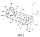
- FIG. 2is a perspective view of a first embodiment of the safety needle inserter of the instant invention
- FIG. 3is an enlarged view of the interconnection between the base and the arm of the safety needle inserter of the instant invention
- FIG. 4is another view of the interconnection between the arm and the base of the safety needle inserter of the instant invention.
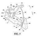
- FIG. 5is another embodiment of the safety needle inserter of the instant invention showing in particular the location of the tip of the needle, or sharp cannula, positioned within the bore of the base.
- FIG. 6is a side view of another embodiment of the safety needle inserter of the instant invention, with the arm of the inserter shown lying longitudinally along the base and the sharp cannula extending downwardly from the base;
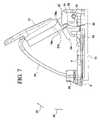
- FIG. 7is another view of the safety needle inserter of the FIG. 6 embodiment showing the sharp cannula having been withdrawn from the opening of the base with the tip residing within the bore of the base and the arm having been pivoted upwardly relative to the base;
- FIG. 8is a front perspective view of the safety needle inserter of FIGS. 6 and 7 , sans the sharp cannula, for showing the interrelationship between the locking mechanisms at the uprights of the base and the end of the arm hingedly connected to the uprights of the base;
- FIG. 9shows the portal access device of the instant invention in which the safety needle inserter component of the instant invention is superposed over an infuser assembly component of the instant invention
- FIG. 10is a bottom view of the portal access device of the instant invention showing in particular the underside of the infuser and the safety needle inserter;
- FIG. 11 a and FIG. 11 bshow the sharp cannula of the safety needle inserter mated axially to the blunt cannula of the infuser and withdrawn from the infuser, respectively;
- FIG. 12 a and FIG. 12 bare respective views of the portal access device showing the mating of the sharp cannula to the blunt cannula and the removal of the sharp cannula from the blunt cannula, respectively.
- FIGS. 1-4The first embodiment of the safety needle inserter device component of the instant invention is shown in FIGS. 1-4 .
- the safety needle inserter 2has a base 4 that has a distal portion 6 and a proximal portion 8 .
- a foam pad or layer 10 coated with an adhesive for adhering base 4 to the patientmay be mounted to the underside, or the lower surface, of base 4 .
- An arm having a first end 14 and a second end 16is hingedly connected to two uprights 18 a and 18 b , respectively, at distal portion 6 of base 4 .
- Two lugs 19are movably journaled to the respective guide holes 20 a and 20 b of the respective uprights 18 a and 18 b , to thereby hingedly and movably connect arm 12 to base 4 . Only lug 19 a is shown in FIG. 2 .
- arm 12When uplifted in the direction as indicated by directional arrow 22 , arm 12 is pivotally moved, via its second end 16 , in an upward direction relative to base 4 .
- a needle, or sharp cannula 24is mounted to the underside of arm 12 , at its first end 14 .
- needle 24extends downwardly from base 4 through an opening 44 , best shown in the embodiment of FIG. 5 .
- sharp cannula 24has a tip 26 that is adapted to insert into the patient and penetrate the septum of a portal reservoir, or port, implanted to a patient. Note that even though the sharp cannula 24 of the safety needle inserter of the FIGS.
- 1-4 embodimentis a unitary needle mounted vertically from arm 12
- a right angle needlethat has a vertical portion and a horizontal portion embedded in arm 12 may also be used as the safety needle inserter of the instant invention.
- the distal end of the horizontal portion of the right angle needlemay be connected to a catheter, tube or tubing so that fluid may be conveyed to, or removed from, the sharp cannula 24 .
- the sharp cannulamay be usable singly, or coaxially with a blunt cannula of the to be discussed infuser component of the instant invention.
- FIGS. 3 and 4illustrate the locking mechanisms at the respective uprights 18 a and 18 b at distal portion 6 of base 4 and the corresponding coacting locking mechanisms formed at end 16 of arm 12 for preventing further movement of arm 12 , once it has been pivotally moved relative to base 4 when tip 26 of sharp cannula 24 is positioned within a bore 42 formed in base 4 , best illustrated in the embodiment of the safety needle inserter shown in FIG. 5 .
- the different portions at both arm 12 and uprights 18 of base 4may be considered as different parts of a single locking mechanism that cooperatively work together to lock arm 12 in place relative to base 4 , and more importantly to fixedly maintain tip 26 of sharp cannula 24 within bore 42 formed at proximal portion 8 of base 4 , so as to prevent tip 26 from being exposed or fluid thereon from being splattered, when sharp cannula 24 is withdrawn from the patient.
- the lock mechanismsor the portions of the lock mechanism, as shown in the FIGS. 3 and 4 embodiment, comprise a leg 28 and a boss 30 at the respective sides of end 16 of arm 12 .
- the lock mechanisms, or the parts of the lock mechanism, at distal portion 6 of base 4are configured as a shoulder 32 at upright 18 a and a groove or recess 34 at upright 18 b.
- a notch 36is provided on base 4 as a rest for boss 32 .
- a channel 38is molded into base 4 to allow the downward extending portion 12 a of arm 12 to fit in alignment to base 4 , when arm 12 is in the position vis-a-vis base 4 as shown in FIGS. 1 and 2 .
- a void 40is provided on base 4 to receive leg 28 of arm 12 so that arm 12 could lie substantially along base 4 as shown in FIGS. 1 and 2 .
- FIG. 5is an illustration of a second embodiment of the safety needle inserter of the instant invention.
- the safety needle inserter of the FIG. 5 embodimentfunctions in the same way as the embodiment shown in FIGS. 1-4 .
- the components that are the same as those of the earlier disclosed embodimentare labeled the same.
- the tip 26 of sharp cannula 24when withdrawn from the portal reservoir and the patient, is maintained within a bore 42 that is formed at the proximal portion 8 of base 4 .
- bore 42is defined between opening 44 at the underside or lower surface of base 4 and an opening 44 a at the upper side or upper surface 46 of base 4 .
- a dam 48extends from proximal portion 8 of base 4 and serves as an additional safety feature to ensure that the tip 26 of cannula 24 could not be forcibly removed from bore 42 .
- top 48 a of dam 48provides a rest stop for arm 12 , with end 14 thereof resting against top surface 48 a , when needle 26 is axially fitted to the blunt cannula of the infuser.
- Dam 48also provides a point for the needle inserter where a user can apply the force needed to insert the sharp cannula into the patient and, as will be described infra, penetrate the septum of the portal reservoir implanted to the patient.
- the same dam structureis provided in the earlier embodiment of the safety needle inserter.
- FIG. 5 embodiment of the safety needle inserteris different from the embodiment shown in FIGS. 1-4 in that instead of using separate components for preventing upward and downward movements of arm 12 , a pair of bosses 50 provided at the end 16 of arm 12 would bias against the respective front faces 52 a of a pair of uprights 52 that are formed at the distal portion of base 4 , to prevent further upward movement of arm 12 relative to base 4 .
- a second pair of uprights 54also extend from base 4 to grasp arm 12 , when arm 12 lies longitudinally along base 4 with cannula 24 extending though opening 44 .
- the holding of arm 12 by uprights 54is by way of corresponding fingers 54 a and 54 b at the uprights 54 .
- uprights 54along with base 4 and arm 12 , are all molded from medical plastics material, when arm 12 is moved upwardly per directional arrow 22 , fingers 54 b of the uprights 54 would give away until end portion 16 of arm 12 passes both fingers 54 a and 54 b . At which time uprights 54 would return to their respective original positions so that the lower surface 16 a of end portion 16 of arm 12 would rest against the respective inclines 54 b of uprights 54 , thereby preventing arm 12 from any downward movement as indicated per directional arrow 36 .
- FIGS. 6-8A third embodiment of the safety needle inserter of the instant invention is shown in FIGS. 6-8 .
- This embodimentis a modification of the simplified embodiment shown in FIG. 5 in that uprights 54 have been reconfigured to allow additional flexibility by the adding of a notch 56 thereto.
- each of uprights 54would tend to flex away, until the underside 16 a of arm 12 clears the top edge 54 b of the respective uprights 54 .
- uprights 54will return to their respective memorized original positions so as to move upper surfaces 54 b of uprights 54 under the bottom surface 16 a of arm 12 and more specifically those surfaces of the bosses 52 , or areas proximate thereto, to thereby prevent downward movement of arm 12 along the direction as indicated by directional arrow 36 .
- respective grooves or recesses 34are provided at the uprights 52 , so that bosses 52 are caught by the front surfaces of the respective recesses 34 , designated by 34 a , so as to prevent arm 12 from any further upward movement as indicated by directional arrow 22 .
- the tip of needle 24is fixedly retained within a bore at proximal portion 8 of base 4 .
- FIGS. 6-8clearly show that arm 12 is hingedly connected to base 4 by way of its lugs 19 movably journaled to apertures 20 of uprights 52 .
- a foam layer or pad 10 with an adhesive undersidemay be provided to the safety needle inserter for enhancing the comfort to the patient, when the inserter is used individually.
- foam 10is not needed when the safety needle inserter is to be used with the infuser.
- a safety needle inserter 2as described above is used in conjunction with an infuser or a low-profile portal access assembly 60 that includes an infuser body or housing 62 , a blunt cannula 64 attached to the underside of body 62 and a catheter or tube 66 that is attached to a side of body 62 .
- infuser body 62is formed as a domed shaped housing or a manifold that has a self-sealing septum 68 at its top in axial alignment with blunt cannula 64 .
- housing 68is substantially hollow, infuser 60 in essence provides a fluid storage depot through which a communication path between tube 66 and blunt cannula 64 is established.
- tube 66is connected to a fluid store 70 , which may be a syringe or a pump or some other storage device that is adapted for storing fluids or medicaments to be infused to the patient.
- a fluid store 70which may be a syringe or a pump or some other storage device that is adapted for storing fluids or medicaments to be infused to the patient.
- fluid in the portal reservoirmay be retrieved by means of the fluid communication path established between blunt cannula 64 and tube 66 via infuser body 62 .
- the safety needle inserter component of the portal access device of the instant inventionhas its proximal portion configured as a dome 72 so that it may be form fitted over infuser body 62 .
- infuser body 62may have different dimensions and be configured as different shapes, for example a rectangular shaped housing.
- the proximal portion of base 4 of the safety needle inserterwould also be rectangularly shaped so that it may form fit over the hypothetical rectangular shaped infuser body.
- the remainder portion of base 4may be configured to fit over tube 66 , by having a channel 74 formed at its underside as shown by the bottom view of the safety needle inserter in FIG. 10 .
- safety needle inserter component of the portal access deviceas shown in FIGS. 9 and 10 is the same as that discussed earlier with respect to the various embodiments of the safety needle inserter.
- safety needle inserter 2When used with infuser assembly 60 , safety needle inserter 2 is placed over infuser assembly 60 so that needle or sharp cannula 24 of the needle insertion device 2 is inserted through septum 68 into infuser body 62 and axially through blunt cannula 64 until the tip 26 of sharp cannula 24 protrudes or is exposed beyond the tip 64 a of blunt cannula 64 .
- proximal portion of needle inserter 2By configuring the proximal portion of needle inserter 2 to form fit over the infuser housing 62 , and with arm 12 , in particular proximal portion 14 thereof, resting on dam 48 of base 4 , a user can readily insert the combination blunt cannula 64 /sharp cannula 24 into a patient, designated by 74 in FIGS. 11 and 12 , so that the tip 26 of cannula 24 may be inserted through a septum opening 36 of a port or portal reservoir 78 implanted in patient 74 , per shown in FIGS. 11 a and 12 a .
- a window 80may be formed at the proximal portion 8 of base 4 to enable the user to confirm that the dome 72 of the safety needle inserter 2 is appropriately form fitted over infuser body 62 , to thereby ensure that cannula 24 be inserted correctly into infuser body 62 and through blunt cannula 64 .
- the safety needle insertermay be removed from the infuser assembly by lifting arm 12 of the needle inserter relative to its base 4 , per shown in FIGS. 11 b and 12 b .
- arm 12is prevented from further movement both upwardly and downwardly relative to base 4 , as per discussion supra, so that tip 26 of needle 24 is fixedly maintained or positioned within the bore 42 formed in base 4 .
- infuser body 62may be provided with a pair of wings 82 , either by bonding or molding, so that the user can hold wings 82 against the body or the skin surface of the patient, while lifting safety needle inserter 2 away from infuser assembly 60 .
- infuser assembly 60may be secured to the skin surface of the patient, by an adhesive layer preformed at the underside of infuser body 62 or an adhesive tape for example, so that a fluid communication path is continuously established between the portal reservoir 78 implanted in the patient and the fluid store 70 .
- medicaments and other fluidsare easily and readily infused to the patient through portal reservoir 78 and its associated catheter or tubing 79 .
- infuser assembly 60provides a long term access to the portal reservoir 78 without further risks of sharps injury, as the safety needle inserter 2 has been removed and no further reinsertion is needed.
- the cannula 64 for infuser assembly 60is a blunt cannula, when the infuser assembly is removed, there is no risk of injury to the patient or the user, and therefore no sharps protection is required.
- infuser assembly 60may be re-accessed through the self-sealing septum 68 , either to provide direct coaxial access to the chamber of the portal reservoir 78 , or access to the portal outlet catheter 79 , for example by a radially flexible and axially stiff (pushable) wire or rod so that the fluid communication path may be threaded or rodded to clear any obstructions that may have occurred in either the portal reservoir or catheter 79 connected to the portal reservoir though which the medicament is fed to the patient.
- a right angle needle insertion devicesuch as that described earlier, or as disclosed in the above-discussed '015 patent, may be used to directly access the internal chamber of the portal reservoir, either via the blunt cannula of the infuser assembly or separate from the infuser assembly, so that the particular fluid may be fed through the catheter or tubing connected to the horizontal portion of the right angle needle directly into the portal reservoir.
- the removal of fluid from the portal reservoirmay be effected in the reverse manner by suctioning the fluid in the portal reservoir through a right angle needle inserter, by applying suction to the catheter connected to the horizontal portion of the right angle needle while the vertical portion of the right angle needle is in fluid communication with the portal reservoir.
Landscapes
- Health & Medical Sciences (AREA)
- Vascular Medicine (AREA)
- Engineering & Computer Science (AREA)
- Anesthesiology (AREA)
- Biomedical Technology (AREA)
- Heart & Thoracic Surgery (AREA)
- Hematology (AREA)
- Life Sciences & Earth Sciences (AREA)
- Animal Behavior & Ethology (AREA)
- General Health & Medical Sciences (AREA)
- Public Health (AREA)
- Veterinary Medicine (AREA)
- Infusion, Injection, And Reservoir Apparatuses (AREA)
Abstract
Description
Claims (26)
Priority Applications (9)
| Application Number | Priority Date | Filing Date | Title |
|---|---|---|---|
| US11/318,485US7510543B2 (en) | 2005-12-28 | 2005-12-28 | Removable sharps device for accessing a portal reservoir |
| US11/318,484US7549976B2 (en) | 2005-12-28 | 2005-12-28 | Portal access device with removable sharps protection |
| EP06846070AEP1968689B1 (en) | 2005-12-28 | 2006-12-27 | Portal access device with removable sharps protection |
| JP2008548704AJP5008678B2 (en) | 2005-12-28 | 2006-12-27 | Portal access device that can protect the removable point |
| PCT/US2006/049358WO2007079115A2 (en) | 2005-12-28 | 2006-12-27 | Removable sharps device for accessing a portal reservoir |
| ES06846070TES2387103T3 (en) | 2005-12-28 | 2006-12-27 | Portal access device with removable protection against sharp instruments |
| PCT/US2006/049357WO2007079114A2 (en) | 2005-12-28 | 2006-12-27 | Portal access device with removable sharps protection |
| AU2006332792AAU2006332792B2 (en) | 2005-12-28 | 2006-12-27 | Portal access device with removable sharps protection |
| CA2633773ACA2633773C (en) | 2005-12-28 | 2006-12-27 | Portal access device with removable sharps protection |
Applications Claiming Priority (2)
| Application Number | Priority Date | Filing Date | Title |
|---|---|---|---|
| US11/318,485US7510543B2 (en) | 2005-12-28 | 2005-12-28 | Removable sharps device for accessing a portal reservoir |
| US11/318,484US7549976B2 (en) | 2005-12-28 | 2005-12-28 | Portal access device with removable sharps protection |
Publications (2)
| Publication Number | Publication Date |
|---|---|
| US20070149920A1 US20070149920A1 (en) | 2007-06-28 |
| US7549976B2true US7549976B2 (en) | 2009-06-23 |
Family
ID=39203309
Family Applications (2)
| Application Number | Title | Priority Date | Filing Date |
|---|---|---|---|
| US11/318,485Active2026-12-05US7510543B2 (en) | 2005-12-28 | 2005-12-28 | Removable sharps device for accessing a portal reservoir |
| US11/318,484Active2026-12-12US7549976B2 (en) | 2005-12-28 | 2005-12-28 | Portal access device with removable sharps protection |
Family Applications Before (1)
| Application Number | Title | Priority Date | Filing Date |
|---|---|---|---|
| US11/318,485Active2026-12-05US7510543B2 (en) | 2005-12-28 | 2005-12-28 | Removable sharps device for accessing a portal reservoir |
Country Status (2)
| Country | Link |
|---|---|
| US (2) | US7510543B2 (en) |
| WO (2) | WO2007079115A2 (en) |
Cited By (6)
| Publication number | Priority date | Publication date | Assignee | Title |
|---|---|---|---|---|
| EP2575915A4 (en)* | 2010-06-04 | 2014-08-06 | Smiths Medical Asd Inc | ANTIMICROBIAL LUBRICANT |
| US9011388B2 (en) | 2010-06-04 | 2015-04-21 | Smiths Medical Asd, Inc. | Passive safety portal device |
| US11446434B2 (en) | 2019-02-22 | 2022-09-20 | Deka Products Limited Partnership | Infusion set and inserter assembly systems and methods |
| USD1043976S1 (en) | 2022-08-26 | 2024-09-24 | Deka Products Limited Partnership | Fluid transfer connector |
| USD1057941S1 (en) | 2022-08-26 | 2025-01-14 | Deka Products Limited Partnership | Patient care assembly component |
| USD1090862S1 (en) | 2022-08-26 | 2025-08-26 | Deka Products Limited Partnership | Adhering assembly for medical devices and the like |
Families Citing this family (60)
| Publication number | Priority date | Publication date | Assignee | Title |
|---|---|---|---|---|
| US8177762B2 (en) | 1998-12-07 | 2012-05-15 | C. R. Bard, Inc. | Septum including at least one identifiable feature, access ports including same, and related methods |
| US9314228B2 (en) | 2002-05-31 | 2016-04-19 | Vidacare LLC | Apparatus and method for accessing the bone marrow |
| US20070049945A1 (en) | 2002-05-31 | 2007-03-01 | Miller Larry J | Apparatus and methods to install, support and/or monitor performance of intraosseous devices |
| US8668698B2 (en) | 2002-05-31 | 2014-03-11 | Vidacare Corporation | Assembly for coupling powered driver with intraosseous device |
| US7811260B2 (en) | 2002-05-31 | 2010-10-12 | Vidacare Corporation | Apparatus and method to inject fluids into bone marrow and other target sites |
| US10973545B2 (en) | 2002-05-31 | 2021-04-13 | Teleflex Life Sciences Limited | Powered drivers, intraosseous devices and methods to access bone marrow |
| US7951089B2 (en) | 2002-05-31 | 2011-05-31 | Vidacare Corporation | Apparatus and methods to harvest bone and bone marrow |
| US11298202B2 (en) | 2002-05-31 | 2022-04-12 | Teleflex Life Sciences Limited | Biopsy devices and related methods |
| US7850620B2 (en) | 2002-05-31 | 2010-12-14 | Vidacare Corporation | Biopsy devices and related methods |
| EP2039298B1 (en) | 2002-05-31 | 2017-10-25 | Vidacare LLC | Apparatus to access bone marrow |
| US9451968B2 (en) | 2002-05-31 | 2016-09-27 | Vidacare LLC | Powered drivers, intraosseous devices and methods to access bone marrow |
| US8641715B2 (en) | 2002-05-31 | 2014-02-04 | Vidacare Corporation | Manual intraosseous device |
| US8690791B2 (en) | 2002-05-31 | 2014-04-08 | Vidacare Corporation | Apparatus and method to access the bone marrow |
| US11337728B2 (en) | 2002-05-31 | 2022-05-24 | Teleflex Life Sciences Limited | Powered drivers, intraosseous devices and methods to access bone marrow |
| US8142365B2 (en) | 2002-05-31 | 2012-03-27 | Vidacare Corporation | Apparatus and method for accessing the bone marrow of the sternum |
| US10973532B2 (en) | 2002-05-31 | 2021-04-13 | Teleflex Life Sciences Limited | Powered drivers, intraosseous devices and methods to access bone marrow |
| US9072543B2 (en) | 2002-05-31 | 2015-07-07 | Vidacare LLC | Vascular access kits and methods |
| US9504477B2 (en) | 2003-05-30 | 2016-11-29 | Vidacare LLC | Powered driver |
| CN101536926B (en) | 2004-01-26 | 2012-07-18 | 维达保健公司 | Manual interosseous device |
| US7815642B2 (en) | 2004-01-26 | 2010-10-19 | Vidacare Corporation | Impact-driven intraosseous needle |
| US8998848B2 (en) | 2004-11-12 | 2015-04-07 | Vidacare LLC | Intraosseous device and methods for accessing bone marrow in the sternum and other target areas |
| JP5484674B2 (en) | 2005-03-04 | 2014-05-07 | シー・アール・バード・インコーポレーテッド | Access port and identification method |
| US7947022B2 (en) | 2005-03-04 | 2011-05-24 | C. R. Bard, Inc. | Access port identification systems and methods |
| US8029482B2 (en) | 2005-03-04 | 2011-10-04 | C. R. Bard, Inc. | Systems and methods for radiographically identifying an access port |
| US9474888B2 (en) | 2005-03-04 | 2016-10-25 | C. R. Bard, Inc. | Implantable access port including a sandwiched radiopaque insert |
| US10307581B2 (en) | 2005-04-27 | 2019-06-04 | C. R. Bard, Inc. | Reinforced septum for an implantable medical device |
| EP3884989B1 (en) | 2005-04-27 | 2022-07-13 | C. R. Bard, Inc. | Vascular access port |
| EP1874393B1 (en) | 2005-04-27 | 2017-09-06 | C.R.Bard, Inc. | Infusion apparatuses |
| US7510543B2 (en)* | 2005-12-28 | 2009-03-31 | Smiths Medical Md, Inc. | Removable sharps device for accessing a portal reservoir |
| US8944069B2 (en) | 2006-09-12 | 2015-02-03 | Vidacare Corporation | Assemblies for coupling intraosseous (IO) devices to powered drivers |
| EP2073728B1 (en) | 2006-09-12 | 2018-11-07 | Teleflex Medical Devices S.à.r.l. | Biopsy device |
| EP2068743B1 (en) | 2006-09-12 | 2017-03-15 | Vidacare LLC | Medical procedures trays, kits and related methods |
| EP3189787B1 (en) | 2006-09-12 | 2019-01-09 | Teleflex Medical Devices S.à.r.l. | Medical procedures trays and related methods |
| US8974410B2 (en) | 2006-10-30 | 2015-03-10 | Vidacare LLC | Apparatus and methods to communicate fluids and/or support intraosseous devices |
| US9642986B2 (en) | 2006-11-08 | 2017-05-09 | C. R. Bard, Inc. | Resource information key for an insertable medical device |
| US9265912B2 (en) | 2006-11-08 | 2016-02-23 | C. R. Bard, Inc. | Indicia informative of characteristics of insertable medical devices |
| US7981049B2 (en)* | 2006-12-13 | 2011-07-19 | Devicor Medical Products, Inc. | Engagement interface for biopsy system vacuum module |
| ES2651269T3 (en) | 2007-06-20 | 2018-01-25 | Medical Components, Inc. | Venous reservoir with molded indications and / or radiopacas |
| US9610432B2 (en) | 2007-07-19 | 2017-04-04 | Innovative Medical Devices, Llc | Venous access port assembly with X-ray discernable indicia |
| WO2009012385A1 (en) | 2007-07-19 | 2009-01-22 | Medical Components, Inc. | Venous access port assembly with x-ray discernable indicia |
| US9579496B2 (en) | 2007-11-07 | 2017-02-28 | C. R. Bard, Inc. | Radiopaque and septum-based indicators for a multi-lumen implantable port |
| ES2906416T3 (en) | 2008-10-31 | 2022-04-18 | Bard Inc C R | Systems and methods to identify an access road |
| US11890443B2 (en) | 2008-11-13 | 2024-02-06 | C. R. Bard, Inc. | Implantable medical devices including septum-based indicators |
| US8932271B2 (en) | 2008-11-13 | 2015-01-13 | C. R. Bard, Inc. | Implantable medical devices including septum-based indicators |
| EP2451512A1 (en) | 2009-07-07 | 2012-05-16 | C.R. Bard Inc. | Extensible internal bolster for a medical device |
| ES2695907T3 (en) | 2009-11-17 | 2019-01-11 | Bard Inc C R | Overmolded access port that includes anchoring and identification features |
| WO2011097311A2 (en) | 2010-02-02 | 2011-08-11 | Vidacare Corporation | Intraosseous-needle stabilizer and methods |
| DE202010000443U1 (en) | 2010-03-23 | 2011-08-08 | Süddeutsche Feinmechanik GmbH | The cannula assembly |
| USD676955S1 (en) | 2010-12-30 | 2013-02-26 | C. R. Bard, Inc. | Implantable access port |
| USD682416S1 (en) | 2010-12-30 | 2013-05-14 | C. R. Bard, Inc. | Implantable access port |
| ES2765024T3 (en) | 2011-02-09 | 2020-06-05 | Becton Dickinson Co | Foldable insert for drug delivery infusion set |
| WO2013009901A2 (en) | 2011-07-11 | 2013-01-17 | Vidacare Corporation | Sternal locators and associated systems and methods |
| EP2591815A1 (en)* | 2011-11-10 | 2013-05-15 | Debiotech S.A. | Patch kit and infusion set |
| US9750396B2 (en) | 2011-12-12 | 2017-09-05 | Smiths Medical Asd, Inc. | Variable length portal access device |
| US20170189655A1 (en)* | 2014-05-27 | 2017-07-06 | Health Research, Inc. | System and method for draining cerebrospinal fluid |
| CN104248790B (en)* | 2014-09-04 | 2017-04-26 | 肖程午 | Intelligent transfusion device |
| US10576207B2 (en)* | 2015-10-09 | 2020-03-03 | West Pharma. Services IL, Ltd. | Angled syringe patch injector |
| US11318254B2 (en) | 2015-10-09 | 2022-05-03 | West Pharma. Services IL, Ltd. | Injector needle cap remover |
| JP6885960B2 (en) | 2016-01-21 | 2021-06-16 | ウェスト ファーマ サービシーズ イスラエル リミテッド | Drug delivery device with visual indicators |
| BR112021012644A2 (en)* | 2018-12-27 | 2021-09-08 | Poly Medicure Limited | NEEDLES THAT HAVE A SAFETY MECHANISM |
Citations (36)
| Publication number | Priority date | Publication date | Assignee | Title |
|---|---|---|---|---|
| US4755173A (en)* | 1986-02-25 | 1988-07-05 | Pacesetter Infusion, Ltd. | Soft cannula subcutaneous injection set |
| US4813939A (en) | 1987-12-04 | 1989-03-21 | Joel Marcus | Winged infusion apparatus for patient implantable access ports |
| US5135502A (en) | 1987-12-03 | 1992-08-04 | Medfusion Inc. | Solid introducer for catheter to a port and method of use |
| US5242415A (en) | 1992-08-14 | 1993-09-07 | L-Vad Technology, Inc. | Percutaneous access device |
| US5403283A (en) | 1993-10-28 | 1995-04-04 | Luther Medical Products, Inc. | Percutaneous port catheter assembly and method of use |
| US5545143A (en)* | 1993-01-21 | 1996-08-13 | T. S. I. Medical | Device for subcutaneous medication delivery |
| US5562617A (en) | 1994-01-18 | 1996-10-08 | Finch, Jr.; Charles D. | Implantable vascular device |
| US5607407A (en) | 1994-05-09 | 1997-03-04 | Tolkoff; Marc J. | Catheter assembly |
| US5738660A (en) | 1994-10-27 | 1998-04-14 | Luther Medical Products, Inc. | Percutaneous port catheter assembly and method of use |
| US5743891A (en) | 1996-10-25 | 1998-04-28 | Act Medical, Inc. | Subcutaneous safety catheter assembly |
| WO1998057683A1 (en) | 1997-06-16 | 1998-12-23 | Elan Corporation, Plc. | Pre-filled drug-delivery device and method of manufacture and assembly of same |
| US5858001A (en) | 1995-12-11 | 1999-01-12 | Elan Medical Technologies Limited | Cartridge-based drug delivery device |
| US5858005A (en) | 1997-08-27 | 1999-01-12 | Science Incorporated | Subcutaneous infusion set with dynamic needle |
| US5989239A (en) | 1997-01-21 | 1999-11-23 | Vasca, Inc. | Method and apparatus for percutaneously accessing an implanted port |
| US5997524A (en) | 1997-07-18 | 1999-12-07 | Vasca, Inc. | Catheter assembly for percutaneous access to subcutaneous port |
| US6039712A (en) | 1997-11-04 | 2000-03-21 | Terence M. Fogarty | Implantable injection port |
| US6053901A (en) | 1994-01-18 | 2000-04-25 | Vasca, Inc. | Subcutaneously implanted cannula and method for arterial access |
| US6120492A (en) | 1997-07-18 | 2000-09-19 | Vasca, Inc. | Method and apparatus for percutaneously accessing an implanted port |
| US6186982B1 (en)* | 1998-05-05 | 2001-02-13 | Elan Corporation, Plc | Subcutaneous drug delivery device with improved filling system |
| US6355021B1 (en)* | 1998-07-14 | 2002-03-12 | Maersk Medical A/S | Medical puncturing device |
| US20020095138A1 (en)* | 2001-01-05 | 2002-07-18 | Lynch George R. | Pivoting joint infusion assembly |
| US20020123740A1 (en)* | 2000-11-09 | 2002-09-05 | Flaherty J. Christopher | Transcutaneous delivery means |
| US6500150B1 (en)* | 1997-06-16 | 2002-12-31 | Elan Pharma International Limited | Pre-filled drug-delivery device and method of manufacture and assembly of same |
| US6607511B2 (en) | 2001-08-09 | 2003-08-19 | Mdc Investment Holdings, Inc. | Medical device with safety flexible needle |
| US6613015B2 (en) | 2001-10-04 | 2003-09-02 | Deltec, Inc. | Right angle safety needle |
| US6676633B2 (en) | 2001-10-24 | 2004-01-13 | Horizon Medical Products, Inc. | Intravascular administration set needle safety device |
| US20040049159A1 (en) | 2000-12-08 | 2004-03-11 | Barrus Roy L. | Safety shield for medical needles |
| US6719721B1 (en) | 2000-10-23 | 2004-04-13 | Elizabeth Okazaki | Safety port needle assembly |
| US6736797B1 (en) | 1998-06-19 | 2004-05-18 | Unomedical A/S | Subcutaneous infusion set |
| US6830562B2 (en)* | 2001-09-27 | 2004-12-14 | Unomedical A/S | Injector device for placing a subcutaneous infusion set |
| US20050049553A1 (en) | 2003-08-27 | 2005-03-03 | Triplett Daniel J. | Safety needle with positive flush |
| US6926693B2 (en)* | 2002-02-04 | 2005-08-09 | Benlan, Inc | Drug delivery needle device |
| US20060200073A1 (en)* | 2003-07-08 | 2006-09-07 | Novo Nordisk A/S | Portable drug delivery device having an encapsulated needle |
| US20060253076A1 (en) | 2005-04-27 | 2006-11-09 | C.R. Bard, Inc. | Infusion apparatuses and methods of use |
| US20060264898A1 (en) | 2005-04-27 | 2006-11-23 | Beasley Jim C | Infusion apparatuses and related methods |
| US20070149921A1 (en)* | 2005-12-28 | 2007-06-28 | Smiths Medical Md, Inc. | Removable sharps device for accessing a portal reservoir |
Family Cites Families (2)
| Publication number | Priority date | Publication date | Assignee | Title |
|---|---|---|---|---|
| US4183939A (en)* | 1978-09-01 | 1980-01-15 | The Dow Chemical Company | Glaucine analgesic method |
| EP1082151A1 (en) | 1998-06-04 | 2001-03-14 | ELAN CORPORATION, Plc | Gas driven drug delivery device |
- 2005
- 2005-12-28USUS11/318,485patent/US7510543B2/enactiveActive
- 2005-12-28USUS11/318,484patent/US7549976B2/enactiveActive
- 2006
- 2006-12-27WOPCT/US2006/049358patent/WO2007079115A2/enactiveApplication Filing
- 2006-12-27WOPCT/US2006/049357patent/WO2007079114A2/enactiveApplication Filing
Patent Citations (38)
| Publication number | Priority date | Publication date | Assignee | Title |
|---|---|---|---|---|
| US4755173A (en)* | 1986-02-25 | 1988-07-05 | Pacesetter Infusion, Ltd. | Soft cannula subcutaneous injection set |
| US5135502A (en) | 1987-12-03 | 1992-08-04 | Medfusion Inc. | Solid introducer for catheter to a port and method of use |
| US4813939A (en) | 1987-12-04 | 1989-03-21 | Joel Marcus | Winged infusion apparatus for patient implantable access ports |
| US5242415A (en) | 1992-08-14 | 1993-09-07 | L-Vad Technology, Inc. | Percutaneous access device |
| US5545143A (en)* | 1993-01-21 | 1996-08-13 | T. S. I. Medical | Device for subcutaneous medication delivery |
| US5403283A (en) | 1993-10-28 | 1995-04-04 | Luther Medical Products, Inc. | Percutaneous port catheter assembly and method of use |
| US5569217A (en) | 1993-10-28 | 1996-10-29 | Luther Medical Products, Inc. | Percutaneous port catheter assembly and method of use |
| US5562617A (en) | 1994-01-18 | 1996-10-08 | Finch, Jr.; Charles D. | Implantable vascular device |
| US6053901A (en) | 1994-01-18 | 2000-04-25 | Vasca, Inc. | Subcutaneously implanted cannula and method for arterial access |
| US5853394A (en) | 1994-05-09 | 1998-12-29 | Tolkoff; Marc Joshua | Catheter |
| US5607407A (en) | 1994-05-09 | 1997-03-04 | Tolkoff; Marc J. | Catheter assembly |
| US5738660A (en) | 1994-10-27 | 1998-04-14 | Luther Medical Products, Inc. | Percutaneous port catheter assembly and method of use |
| US5858001A (en) | 1995-12-11 | 1999-01-12 | Elan Medical Technologies Limited | Cartridge-based drug delivery device |
| US5743891A (en) | 1996-10-25 | 1998-04-28 | Act Medical, Inc. | Subcutaneous safety catheter assembly |
| US5989239A (en) | 1997-01-21 | 1999-11-23 | Vasca, Inc. | Method and apparatus for percutaneously accessing an implanted port |
| US6500150B1 (en)* | 1997-06-16 | 2002-12-31 | Elan Pharma International Limited | Pre-filled drug-delivery device and method of manufacture and assembly of same |
| WO1998057683A1 (en) | 1997-06-16 | 1998-12-23 | Elan Corporation, Plc. | Pre-filled drug-delivery device and method of manufacture and assembly of same |
| US6120492A (en) | 1997-07-18 | 2000-09-19 | Vasca, Inc. | Method and apparatus for percutaneously accessing an implanted port |
| US5997524A (en) | 1997-07-18 | 1999-12-07 | Vasca, Inc. | Catheter assembly for percutaneous access to subcutaneous port |
| US5858005A (en) | 1997-08-27 | 1999-01-12 | Science Incorporated | Subcutaneous infusion set with dynamic needle |
| US6039712A (en) | 1997-11-04 | 2000-03-21 | Terence M. Fogarty | Implantable injection port |
| US6186982B1 (en)* | 1998-05-05 | 2001-02-13 | Elan Corporation, Plc | Subcutaneous drug delivery device with improved filling system |
| US6736797B1 (en) | 1998-06-19 | 2004-05-18 | Unomedical A/S | Subcutaneous infusion set |
| US6355021B1 (en)* | 1998-07-14 | 2002-03-12 | Maersk Medical A/S | Medical puncturing device |
| US6719721B1 (en) | 2000-10-23 | 2004-04-13 | Elizabeth Okazaki | Safety port needle assembly |
| US20020123740A1 (en)* | 2000-11-09 | 2002-09-05 | Flaherty J. Christopher | Transcutaneous delivery means |
| US20040049159A1 (en) | 2000-12-08 | 2004-03-11 | Barrus Roy L. | Safety shield for medical needles |
| US20020095138A1 (en)* | 2001-01-05 | 2002-07-18 | Lynch George R. | Pivoting joint infusion assembly |
| US6607511B2 (en) | 2001-08-09 | 2003-08-19 | Mdc Investment Holdings, Inc. | Medical device with safety flexible needle |
| US6830562B2 (en)* | 2001-09-27 | 2004-12-14 | Unomedical A/S | Injector device for placing a subcutaneous infusion set |
| US6613015B2 (en) | 2001-10-04 | 2003-09-02 | Deltec, Inc. | Right angle safety needle |
| US6676633B2 (en) | 2001-10-24 | 2004-01-13 | Horizon Medical Products, Inc. | Intravascular administration set needle safety device |
| US6926693B2 (en)* | 2002-02-04 | 2005-08-09 | Benlan, Inc | Drug delivery needle device |
| US20060200073A1 (en)* | 2003-07-08 | 2006-09-07 | Novo Nordisk A/S | Portable drug delivery device having an encapsulated needle |
| US20050049553A1 (en) | 2003-08-27 | 2005-03-03 | Triplett Daniel J. | Safety needle with positive flush |
| US20060253076A1 (en) | 2005-04-27 | 2006-11-09 | C.R. Bard, Inc. | Infusion apparatuses and methods of use |
| US20060264898A1 (en) | 2005-04-27 | 2006-11-23 | Beasley Jim C | Infusion apparatuses and related methods |
| US20070149921A1 (en)* | 2005-12-28 | 2007-06-28 | Smiths Medical Md, Inc. | Removable sharps device for accessing a portal reservoir |
Cited By (7)
| Publication number | Priority date | Publication date | Assignee | Title |
|---|---|---|---|---|
| EP2575915A4 (en)* | 2010-06-04 | 2014-08-06 | Smiths Medical Asd Inc | ANTIMICROBIAL LUBRICANT |
| US9011388B2 (en) | 2010-06-04 | 2015-04-21 | Smiths Medical Asd, Inc. | Passive safety portal device |
| US11446434B2 (en) | 2019-02-22 | 2022-09-20 | Deka Products Limited Partnership | Infusion set and inserter assembly systems and methods |
| US12324899B2 (en) | 2019-02-22 | 2025-06-10 | Deka Products Limited Partnership | Infusion set and inserter assembly systems and methods |
| USD1043976S1 (en) | 2022-08-26 | 2024-09-24 | Deka Products Limited Partnership | Fluid transfer connector |
| USD1057941S1 (en) | 2022-08-26 | 2025-01-14 | Deka Products Limited Partnership | Patient care assembly component |
| USD1090862S1 (en) | 2022-08-26 | 2025-08-26 | Deka Products Limited Partnership | Adhering assembly for medical devices and the like |
Also Published As
| Publication number | Publication date |
|---|---|
| US20070149921A1 (en) | 2007-06-28 |
| US20070149920A1 (en) | 2007-06-28 |
| US7510543B2 (en) | 2009-03-31 |
| WO2007079115A3 (en) | 2007-11-29 |
| WO2007079115A2 (en) | 2007-07-12 |
| WO2007079114A3 (en) | 2007-11-08 |
| WO2007079114A2 (en) | 2007-07-12 |
Similar Documents
| Publication | Publication Date | Title |
|---|---|---|
| US7549976B2 (en) | Portal access device with removable sharps protection | |
| JP5646479B2 (en) | Medicine injection system with reusable and disposable parts | |
| US9821113B2 (en) | Automatic angled infusion set assembly | |
| EP0615768A2 (en) | Device for subcutaneous medication delivery | |
| EP3167922B1 (en) | Slide-activated angled inserter and cantilevered ballistic insertion for intradermal drug infusion | |
| US20080045891A1 (en) | Medication infusion set | |
| KR20070042885A (en) | Safety injector | |
| KR20070114721A (en) | Gateway system | |
| EP2673021A1 (en) | Folding inserter for drug delivery infusion set | |
| US20230060176A1 (en) | Injection Assembly Apparatuses, Systems, and Methods | |
| AU2006332792B2 (en) | Portal access device with removable sharps protection | |
| CA2634246C (en) | Removable sharps device for accessing a portal reservoir | |
| EP3902583B1 (en) | Needle having a safety mechanism | |
| RU2299745C2 (en) | Injection device for mounting set intended for hypodermic injection |
Legal Events
| Date | Code | Title | Description |
|---|---|---|---|
| AS | Assignment | Owner name:SMITHS MEDICAL MD, INC., MINNESOTA Free format text:ASSIGNMENT OF ASSIGNORS INTEREST;ASSIGNORS:MICHELS, LESTER D.;BELING, WILLIAM L.;TRAVIS, RONALD G.;REEL/FRAME:017424/0770 Effective date:20051205 | |
| STCF | Information on status: patent grant | Free format text:PATENTED CASE | |
| AS | Assignment | Owner name:SMITHS MEDICAL ASD, INC., MINNESOTA Free format text:MERGER;ASSIGNOR:SMITHS MEDICAL MD, INC.;REEL/FRAME:023486/0050 Effective date:20060806 | |
| FPAY | Fee payment | Year of fee payment:4 | |
| FPAY | Fee payment | Year of fee payment:8 | |
| AS | Assignment | Owner name:SMITHS MEDICAL ASD, INC., MINNESOTA Free format text:MERGER;ASSIGNOR:SMITHS MEDICAL MD, INC.;REEL/FRAME:041763/0845 Effective date:20090731 | |
| AS | Assignment | Owner name:SMITHS MEDICAL ASD, INC., MINNESOTA Free format text:CORRECTIVE ASSIGNMENT TO CORRECT THE PATENT NUMBERS 7510643 AND 7549976 PREVIOUSLY RECORDED ON REEL 041763 FRAME 0845. ASSIGNOR(S) HEREBY CONFIRMS THE MERGER;ASSIGNOR:SMITHS MEDICAL MD, INC.;REEL/FRAME:042119/0296 Effective date:20090731 | |
| MAFP | Maintenance fee payment | Free format text:PAYMENT OF MAINTENANCE FEE, 12TH YEAR, LARGE ENTITY (ORIGINAL EVENT CODE: M1553); ENTITY STATUS OF PATENT OWNER: LARGE ENTITY Year of fee payment:12 | |
| AS | Assignment | Owner name:WELLS FARGO BANK, NATIONAL ASSOCIATION, AS COLLATERAL AGENT, TEXAS Free format text:SECURITY AGREEMENT;ASSIGNOR:SMITHS MEDICAL ASD, INC.;REEL/FRAME:061179/0320 Effective date:20220815 | |
| AS | Assignment | Owner name:ICU MEDICAL, INC., CALIFORNIA Free format text:MERGER;ASSIGNOR:SMITHS MEDICAL ASD, INC.;REEL/FRAME:069101/0767 Effective date:20240801 |