US7549959B2 - Stimulation arrangement for measurement of physiological signal reactivity - Google Patents
Stimulation arrangement for measurement of physiological signal reactivityDownload PDFInfo
- Publication number
- US7549959B2 US7549959B2US11/743,834US74383407AUS7549959B2US 7549959 B2US7549959 B2US 7549959B2US 74383407 AUS74383407 AUS 74383407AUS 7549959 B2US7549959 B2US 7549959B2
- Authority
- US
- United States
- Prior art keywords
- subject
- measurement probe
- reactivity
- stimulus
- physiological signal
- Prior art date
- Legal status (The legal status is an assumption and is not a legal conclusion. Google has not performed a legal analysis and makes no representation as to the accuracy of the status listed.)
- Active, expires
Links
Images


Classifications
- A—HUMAN NECESSITIES
- A61—MEDICAL OR VETERINARY SCIENCE; HYGIENE
- A61B—DIAGNOSIS; SURGERY; IDENTIFICATION
- A61B5/00—Measuring for diagnostic purposes; Identification of persons
- A61B5/24—Detecting, measuring or recording bioelectric or biomagnetic signals of the body or parts thereof
- A61B5/316—Modalities, i.e. specific diagnostic methods
- A61B5/369—Electroencephalography [EEG]
- A61B5/377—Electroencephalography [EEG] using evoked responses
- A—HUMAN NECESSITIES
- A61—MEDICAL OR VETERINARY SCIENCE; HYGIENE
- A61B—DIAGNOSIS; SURGERY; IDENTIFICATION
- A61B5/00—Measuring for diagnostic purposes; Identification of persons
- A61B5/24—Detecting, measuring or recording bioelectric or biomagnetic signals of the body or parts thereof
- A61B5/316—Modalities, i.e. specific diagnostic methods
- A61B5/318—Heart-related electrical modalities, e.g. electrocardiography [ECG]
- A—HUMAN NECESSITIES
- A61—MEDICAL OR VETERINARY SCIENCE; HYGIENE
- A61B—DIAGNOSIS; SURGERY; IDENTIFICATION
- A61B5/00—Measuring for diagnostic purposes; Identification of persons
- A61B5/02—Detecting, measuring or recording for evaluating the cardiovascular system, e.g. pulse, heart rate, blood pressure or blood flow
- A61B5/0205—Simultaneously evaluating both cardiovascular conditions and different types of body conditions, e.g. heart and respiratory condition
- A—HUMAN NECESSITIES
- A61—MEDICAL OR VETERINARY SCIENCE; HYGIENE
- A61B—DIAGNOSIS; SURGERY; IDENTIFICATION
- A61B5/00—Measuring for diagnostic purposes; Identification of persons
- A61B5/72—Signal processing specially adapted for physiological signals or for diagnostic purposes
- A61B5/7271—Specific aspects of physiological measurement analysis
- A61B5/7285—Specific aspects of physiological measurement analysis for synchronizing or triggering a physiological measurement or image acquisition with a physiological event or waveform, e.g. an ECG signal
Definitions
- the present inventionrelates to the assessment of the reactivity of the central nervous system of a patient by applying an external stimulation to the patient.
- the stimulationis observable on/in a physiological signal, especially an EEG signal.
- physiological signal reactivitythe reactivity observable on/in a physiological signal is termed physiological signal reactivity.
- Neuromonitoringis a subfield of clinical patient monitoring focused on measuring various aspects of brain function and on changes therein caused by neurological diseases, accidents, and drugs commonly used to induce and maintain anesthesia in an operation room or sedation in patients under critical or intensive care.
- Electroencephalographyis a well-established method for assessing brain activity. When measurement electrodes are attached on the skin of the skull surface, the weak biopotential signals generated in brain cortex may be recorded and analyzed.
- the EEGhas been in wide use for decades in basic research of the neural systems of the brain as well as in the clinical diagnosis of various central nervous system diseases and disorders.
- EEG signalis a very sensitive measure of the neuronal derangements, which may reflect in the EEG signal either as changes in membrane potentials or as changes in synaptic transmission. A change in synaptic transmission occurs whenever there is an imbalance between consumption and supply of energy in the brain. This means that the EEG signal serves as an early warning of a developing injury in the brain.
- GCSGlasgow Coma Scale
- an EEG signalmay be of critical value, as it may differentiate between broad categories of psychogenic, epileptic, metabolic-toxic, encephalitic, and focal conditions, for example.
- the EEGIn a healthy sleeping subject, the EEG is reactive to various stimuli depending on the sleep stages.
- a test of the reactivity of the EEG signal to external stimulationis an important assessment tool for a clinician, since it provides significant information regarding the state and outcome of the patient. EEG reactivity may reveal potentially treatable conditions and also provide information of the level of drug-induced sedation. While some conclusions about the probability of a recovery can be drawn from the raw EEG signal as such, it has been shown that reactivity of the EEG signal to stimulation, i.e. a detectable change in the EEG signal after a stimulus as compared to the pre-stimulus situation, is a more specific indicator of a favorable outcome, cf. G. B.
- EEG reactivityis an essential part of the EEG examination of a comatose patient.
- the test of EEG reactivityprovides information regarding the state of a patient for whom the GCS or another observational scoring system is not applicable. This is the case, for example, when neuromuscular blocking agents have been administered to the patient, which makes the patient unable to respond and thus the observational scoring systems inapplicable.
- the EEG reactivityis assessed by an EEG specialist trained to interpret EEG waveforms.
- ICUIntense Care Unit
- doctors or nurseswho are skilled in making GCS-type assessments, are usually not capable of interpreting the EEG waveforms, and therefore a consulting EEG specialist has to be called in for the test of EEG reactivity.
- Various types of stimulisuch as auditory (shouting the patient's name, blowing a horn) and somatosensory (pinching, squeezing, shaking) stimuli, may be applied in the test.
- the EEG specialistannotates the time instant of the stimulation and compares the recorded EEG signal before and after the annotated time instant. Often the EEG signal shows reactivity only to some of the given stimuli; in this case reactivity is considered to be present.
- the test of the EEG reactivityis currently based mainly on manual stimulation performed by a nurse or a doctor, despite the fact that its intensity is often subject to variability between stimulators.
- the stimulationis typically given by manually touching the patient, i.e. the stimulation is sensed by the somatosensory system of the patient. Even if the same person repeats stimulation, its intensity may vary. Comparison of EEG reactivity between different stimulations is in this case difficult because a more intense stimulus may result in a higher response in the EEG signal than a milder stimulus. Standardized stimulation intensity would enable the evaluation of changes in patient's reactivity over a longer time period.
- Standardized stimulation intensitycan be achieved with an automatic stimulation device, such as an NMT (NeuroMuscular Transmission) module, which is used for evaluating muscle response by stimulating a peripheral nerve.
- an automatic stimulation devicecapable of producing a standard stimulation pattern similar to the manual stimulation given by the nursing staff requires normally a dedicated actuator. This is a drawback especially in Intensive Care Units (ICU) and in operation rooms which tend to be crammed with medical appliances. Healthcare professionals are therefore reluctant to introduce new appliances to such points of care.
- This drawbackmay be alleviated to some degree by using a sensor arrangement in which all electrodes and sensors may be connected to a single connector, whereby the amount of cables or hoses between the patient and the monitoring devices may be reduced.
- the sensor arrangementcomprises separate NMT electrodes to stimulate the facial nerves of the patient, and the NMT response is measured through recording electrodes or a mechanical sensor located in the facial area of the patient.
- Another drawback related to manual stimulationis that the annotation of the time of the stimulation in the EEG signal may not always be accurate. A precise annotation of the stimulation instant in the EEG signal would facilitate more advanced signal analysis methods, for example averaging of responses to several stimuli.
- the present inventionseeks to alleviate or eliminate the above-mentioned drawbacks.
- the present inventionseeks to provide a novel mechanism for estimating the physiological signal reactivity, especially EEG reactivity of a subject.
- the present inventionfurther seeks to provide an automated measuring arrangement which is easy to introduce in points of care with limited or no space for additional equipment, which enables reliable assessment of changes in the physiological signal reactivity of the subject even during a long time period, and which may stimulate the patient naturally as a doctor or nurse.
- a measurement proberefers to the sensor elements attached to the patient, while the patient monitoring device refers to the actual measurement device that indicates the measurement results to the user.
- the measurement probethus refers to the elements supplying the measured biosignal to the patient monitoring device.
- the measurement probemay comprise a set of electrodes, such as EEG or ECG electrodes, or an arm cuff, such as a NIBP arm cuff.
- a standard patient monitoring deviceis complemented with integrated stimulation functionality that utilizes the existing measurement probe(s) of the device for supplying the stimuli to the patient.
- the stimuliare supplied through the arm cuff of a NIBP probe, while in some other embodiments TENS (transcutaneous electrical nerve stimulation) type functionality, which is normally used for massaging muscles or providing pain relief, is combined with the measurement of physiological signal reactivity without adding to the hardware required.
- TENStranscutaneous electrical nerve stimulation
- the stimulimay be supplied to a NIBP probe when a NIBP measurement is not in progress or the inflation of the cuff during a blood pressure measurement may be utilized as a stimulus for the reactivity measurement.
- electrical stimuli similar to those produced by an NMT modulemay also be supplied through electrodes attached to the skin of the patient.
- the said electrodesmay be, for example, the EEG or ECG electrodes of the patient monitoring device.
- one aspect of the inventionis providing a method for measuring the physiological signal reactivity of a subject.
- the methodincludes receiving physiological signal data from a subject through at least one measurement probe attached to the subject and supplying a stimulus to the subject through a first measurement probe, wherein the first measurement probe is one of the at least one measurement probe.
- the methodfurther includes determining whether reactivity caused by the stimulus is present in physiological signal data received through a second measurement probe, wherein the second measurement probe is one of the at least one measurement probe.
- the apparatusincludes a measurement module configured to receive physiological signal data from a subject and at least one measurement probe attachable to the subject, the at least one measurement probe being configured to produce the physiological signal data.
- the apparatusfurther includes a stimulation module configured to stimulate the subject through a first measurement probe, wherein the first measurement probe is one of the at least one measurement probe and a reactivity determination module configured to determine whether reactivity caused by the stimulus is present in physiological signal data received through a second measurement probe, wherein the second measurement probe is one of the at least one measurement probe.
- the patient monitoring devicemay stimulate the patient at desired time instants by pressurizing the NIBP arm cuff or supplying stimulating current to EEG/ECG electrodes attached to the subject.
- the inventionthus provides an automated stimulation mechanism for the measurement of physiological signal reactivity without any additional probes, or effort from the healthcare personnel. Furthermore, the invention enables generation of stimuli similar to the manual stimulation given by the nursing staff. Especially, the present invention allows stimuli, which the patient feels similarly as the typical grabbing/shaking by a doctor or a nurse.
- a further aspect of the inventionis that of providing a computer program product by means of which known patient monitoring devices may be upgraded and thus their applicability extended to include the assessment of physiological signal reactivity.
- the program productcomprises a first program code portion configured to trigger a stimulus to a subject through a first measurement probe, which is attached to the subject and configured to supply physiological signal data to a monitoring device and a second program code portion configured to determine whether reactivity caused by the stimulus is present in physiological signal data received from the subject through a second measurement probe.
- the strength of the stimulationmay be personalized for each patient. By increasing the strength of the stimulation stepwise and recording the respective physiological reactivity, a suitable strength of stimulation that provides desired level of reactivity may be found for each patient.
- the measurement probeis not moved and the strength of the stimulation is kept constant, the development of the patient's status may be monitored by recording changes in the reactivity to the constant stimulus. This enables the evaluation of the effect of sedative drugs administered to the patient and the information obtained may be used for finding an optimal dose.
- a feature of the EEG signalmay trigger automated stimulation and reactivity determination.
- a change in another physiological signal, such as ECG,may also trigger the stimulus and the reactivity determination.
- the reactivity of the central nervous system of the subjectmay also be determined with respect to another physiological signal than the EEG, such as ECG.
- the inventionthus enables the generation of a standardized, repeatable, and personalized stimulus to a subject for evaluating physiological signal reactivity without the presence of a healthcare professional. It thereby enhances patient monitoring in an ICU environment.
- FIG. 1illustrates one embodiment of the invention utilizing the NIBP measurement of a standard patient monitoring device
- FIG. 2illustrates other embodiments of the invention utilizing the EEG and/or ECG measurement of a standard patient monitoring device
- FIG. 3is a flow diagram illustrating one embodiment for the reactivity determination in the embodiment of FIG. 1 ;
- FIG. 4is a flow diagram illustrating another embodiment for the reactivity determination in the embodiment of FIG. 1 ;
- FIG. 5illustrates one embodiment of the apparatus/system of the invention.
- FIG. 6illustrates an example of the functional entities of the control unit of FIG. 5 .
- FIGS. 1 and 2illustrate various embodiments of the invention for measuring EEG reactivity.
- a standard patient monitoring deviceone or more physiological signals are measured from a patient through signal-specific measurement probes.
- FIGS. 1 and 2show a patient monitoring device 10 capable of measuring EEG, ECG, and NIBP.
- the EEGis measured through a set of EEG electrodes 11 attached to the forehead of the patient 100
- the ECGis measured through a set of ECG electrodes 12 attached to the chest of the patient
- NIBPis measured through an arm cuff 13 placed around the brachium of the patient.
- the number and placement of the electrodes usedmay change depending on the measurement set-up.
- the patient monitoring device 10is provided with an EEG reactivity module 14 for measuring the EEG reactivity.
- the modulereceives EEG signal data measured through the EEG electrodes.
- the modulefurther comprises a stimulation unit 15 for actively stimulating the patient for the evaluation of the reactivity.
- the stimulation unit 15is configured to control the inflation of the arm cuff 13 .
- the EEG reactivity modulemay be introduced by providing the device with a software upgrade enabling the device to perform an EEG reactivity measurement in which the patient is stimulated by inflating the arm cuff to a predetermined pressure for a short period of time.
- FIG. 2illustrates other embodiments in which the stimulation is given by supplying electrical stimuli through selected EEG or ECG electrodes to the patient.
- the EEG reactivity moduleis provided with a signal generator producing the electrical stimuli supplied to the said electrodes.
- the selected EEG or ECG electrodestypically comprise a subset of the EEG or ECG electrode set used by the device to measure EEG or ECG signal data.
- the stimulationmay also involve a combination of the above-mentioned stimuli.
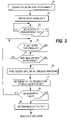
- FIG. 3illustrates one embodiment of the operation of the EEG reactivity module of FIG. 1 .
- the EEG signal measured from the patient(step 31 ) is first digitized and the sampled EEG signal is filtered to exclude high- and low-frequency artifacts (step 32 ).
- the digitized signal samplesare processed as sets of sequential signal samples representing finite time blocks or time windows, commonly termed “epochs”.
- the stimulusmay be given if a stable state is detected for the stimulus and if a NIBP measurement is not in progress (steps 33 - 36 ).
- the EEG reactivity modulemonitors the incoming EEG signal data to ensure that the EEG signal is stable enough prior to the application of the stimulus, i.e. that the signal does not include unwanted distortions when the stimulus is given. Furthermore, the EEG reactivity module monitors whether a NIBP measurement is in progress simultaneously in order not to stimulate the patient during the NIBP measurement.
- a stimulusis given (step 36 ) by pressurizing the arm cuff 13 and releasing the pressure according to a predetermined stimulation pattern, which defines the characteristics of the stimulation, such as the strength and duration of each stimulation pulse.
- the patternmay include one or more stimulation pulses.
- a time label indicating the time instant of the stimulus/stimuliis/are attached to the EEG signal data, i.e. the EEG signal data is temporally aligned with the time instant(s) of the stimulus/stimuli.
- the response caused by the stimulus in the EEG signalis then detected by calculating a measure indicative of the irregularity of the EEG signal in successive time windows both prior to and after the stimulus signal (step 37 ).
- the processmay then check whether the measurement is regarded as valid, i.e. whether the moment of the application of the stimulus was really a suitable moment for the measurement (step 38 ). If this is the case, the process calculates a measure indicative of the EEG reactivity of the subject (step 39 ). In the opposite case, the process returns to step 34 to detect a suitable moment to repeat the stimulation.
- the reactivity measurement and the NIBP measurementare carried out as two separate measurements. However, they may also be combined so that the presence/absence or magnitude of reactivity is determined when the blood pressure is measured. For example, if the blood pressure of the patient is determined automatically at regular intervals, the apparatus may determine the presence/absence or magnitude of reactivity resulting from the inflation of the NIBP measurement cuff. In addition to such periodic measurements, the reactivity may also be determined whenever an event is detected that requires such a measurement. For example, if the EEG measurement indicates a change in the level of the consciousness of the patient or if a significant change is detected in the ECG, the EEG reactivity measurement may be triggered.
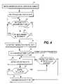
- FIG. 4illustrates another embodiment of the operation of the EEG reactivity module of FIG. 1 .
- Steps 40 - 42correspond, respectively, to steps 31 - 33 of FIG. 3 , i.e. in these steps a time series of EEG signal data is acquired and filtered to exclude high- and low-frequency artifacts, and the need for the EEG reactivity measurement is monitored.
- the EEG reactivity moduleagain checks whether the NIBP cuff is available for the reactivity measurement (step 43 ).
- This embodimentis based on a signal model constructed for the EEG signal from the EEG signal data obtained from the patient.
- the signal data obtained initially from the patientmay therefore be termed reference signal data, since it is employed at step 44 to construct a valid signal model for the current EEG time series.
- the signal model constructedenables prediction of signal values for the time series and a valid signal model meets predetermined criteria in the prediction.
- the signal modelmay be regarded as a valid model as long as the prediction error remains below a certain threshold value.
- a stimulusmay then be given by successively inflating and deflating the NIBP cuff according to patient-specific parameters (step 45 ).
- EEG signal data subsequent to the stimulusis then obtained from the time series at step 46 and the obtained data is utilized to test whether the signal model remains as a valid model for the signal also after the stimulus, step 48 . If the test indicates that the model is not any more valid, it is decided that reactivity is present and the user is informed of the presence of reactivity (step 49 ).
- Various decision rulesmay be employed to decide when the model turns into an invalid model. For example, the model may have to be an invalid model continuously for a certain period, before it is regarded as an invalid model.
- the processdecides that no reactivity is present and quits the testing. The user is informed that no reactivity was found (steps 46 to 49 ).
- FIG. 4illustrates the method for one stimulus signal (inflation/deflation). If a new stimulus is given, the above steps may be repeated, i.e. the signal model is constructed before each stimulus to ensure that the model corresponds to the current EEG of the patient. Furthermore, if the stimulus signal is not supplied immediately after the signal model is available, the validity of the model may be tested already prior to the stimulus to ascertain that the model remains as a valid model until the time instant of the stimulus.
- FIG. 5illustrates one embodiment of the system or apparatus according to the invention. It is assumed here that the apparatus is according to the embodiment of FIG. 2 in which electrical stimuli are supplied to the patient through the same electrodes from where the EEG signal is acquired.
- three EEG electrodes 11 1 to 11 3are attached to the forehead of the patient 100 . Electrodes 11 1 and 11 3 are active electrodes, while the middle electrode 11 2 is a ground electrode.
- the apparatusFor supplying the stimulus signal, the apparatus includes a signal generator 53 connected to electrodes 11 1 and 11 3 through switches 51 and 52 and corresponding wires A and B.
- the current supplied through the electrodesis high enough to cause a sensation, but may also be higher to cause muscle contraction, or even sensation of pain.
- the current suppliedis typically of the order of a few tens of milliamperes.
- the EEG signal data obtained from the electrodesis supplied to an amplifier stage 54 , in which the signal is amplified before being sampled and converted into digitized format in an A/D converter 55 .
- the digitized signal datais supplied to a control unit 56 which may comprise one or more computer units or processors.
- the control unitis provided with a memory or database 57 holding the digitized signal data obtained from the electrodes.
- the memory or databasemay also store the EEG reactivity algorithm and the parameters defining the stimulation pattern, which may be patient-specific.
- the control unitexecutes the stored algorithm, whereby a measure of the EEG reactivity is obtained.
- the control unitcontrols the signal generator and switches 51 , 52 in order to supply a stimulus through electrodes 11 1 and 11 3 to the patient.
- the control unitmay label the EEG signal data obtained during the stimulation so that the actual EEG measurement process is able to identify the EEG segments obtained during the stimulation and is able to inform the user of the device of the said segments in the EEG waveform.
- the reactivity indicator, its trend, and user notificationsmay be displayed on the screen of a monitor 58 , which forms part of the user interface of the device.
- a control unitcomprising one computer unit or one processor may perform the above steps, the processing of the data may also be distributed among different units/processors (servers) within a network, such as a hospital LAN (local area network).
- the apparatus of the inventionmay thus also be implemented as a distributed system.
- the usermay control the operation of the monitoring device through a user input device 59 , such as a keyboard.
- the control unit 56may control the signal generator according to the commands given by the user from the user input device or according to a predetermined stimulation schedule stored in the memory of the apparatus.
- FIG. 6illustrates the operational entities of the control unit.
- the control unitincludes one or more measurement modules 61 for performing the standard physiological measurements of a patient monitoring device, such as an EEG measurement, an ECG measurement, and/or a NIBP measurement.
- the EEG or ECG signal obtained from the patientis also supplied to the reactivity module comprising a first module 62 for determining the reactivity and a second module 63 for supplying the stimuli to the measurement probe 64 in question.
- the determinationincludes applying a time reference corresponding to a stimulus and aligning the physiological signal data temporally with the time reference.
- control unitmay also generate an audio signal when commanding the stimulation module to supply a stimulus signal.
- the content of the audio signalmay be patient-specific.
- the first modulemay comprise a test algorithm for finding out an appropriate stimulation strength for the patient.
- the strength of the stimulusmay be increased in small steps to find out the level at which reactivity is first detected.
- the long-term strength of the stimulusis then set according to the found reactivity threshold.
- the patient-specific reactivity thresholdallows sensitive tracking of changes in patient's status.
- the inventionwas employed for assessing the EEG reactivity of a patient.
- the same mechanismmay be used in connection with said another physiological signal. Therefore, the invention is not necessarily limited to the context of EEG.
- a conventional patient monitormay also be upgraded to enable the monitor to determine the physiological signal reactivity of a patient.
- Such an upgrademay be implemented by delivering to the monitoring device a plug-in software module that enables the device to supply the stimuli through a first measurement probe of the device and to calculate the reactivity based on the time series of the physiological signal data received through a second measurement probe of the device, which may or may not be the same as the first measurement probe.
- the software modulemay be delivered, for example, on a data carrier, such as a CD or a memory card, or through a telecommunications network.
- the plug-in moduleis especially suitable for a monitoring device provided with automatic blood pressure evaluation.
- the actual measurementdisplays the EEG and/or ECG waveform and labels the moments/periods of stimulation so that a clinician may evaluate the EEG/ECG waveform and the reactivity by visually examining the waveform.
Landscapes
- Health & Medical Sciences (AREA)
- Life Sciences & Earth Sciences (AREA)
- Molecular Biology (AREA)
- Surgery (AREA)
- Biophysics (AREA)
- Pathology (AREA)
- Engineering & Computer Science (AREA)
- Biomedical Technology (AREA)
- Heart & Thoracic Surgery (AREA)
- Medical Informatics (AREA)
- Veterinary Medicine (AREA)
- Physics & Mathematics (AREA)
- Animal Behavior & Ethology (AREA)
- General Health & Medical Sciences (AREA)
- Public Health (AREA)
- Cardiology (AREA)
- Psychiatry (AREA)
- Psychology (AREA)
- Measurement And Recording Of Electrical Phenomena And Electrical Characteristics Of The Living Body (AREA)
- Measuring Pulse, Heart Rate, Blood Pressure Or Blood Flow (AREA)
Abstract
Description
Claims (20)
Priority Applications (4)
| Application Number | Priority Date | Filing Date | Title |
|---|---|---|---|
| US11/743,834US7549959B2 (en) | 2007-05-03 | 2007-05-03 | Stimulation arrangement for measurement of physiological signal reactivity |
| EP08155421AEP1987768A1 (en) | 2007-05-03 | 2008-04-30 | Stimulation arrangement for measurement of physiological signal rectivity |
| DE102008021940ADE102008021940A1 (en) | 2007-05-03 | 2008-05-02 | Stimulation arrangement for measuring the physiological signal reactivity |
| NL2001549ANL2001549C2 (en) | 2007-05-03 | 2008-05-06 | Stimulation device for the measurement of physiological signal reactivity. |
Applications Claiming Priority (1)
| Application Number | Priority Date | Filing Date | Title |
|---|---|---|---|
| US11/743,834US7549959B2 (en) | 2007-05-03 | 2007-05-03 | Stimulation arrangement for measurement of physiological signal reactivity |
Publications (2)
| Publication Number | Publication Date |
|---|---|
| US20080275347A1 US20080275347A1 (en) | 2008-11-06 |
| US7549959B2true US7549959B2 (en) | 2009-06-23 |
Family
ID=39712390
Family Applications (1)
| Application Number | Title | Priority Date | Filing Date |
|---|---|---|---|
| US11/743,834Active2027-05-23US7549959B2 (en) | 2007-05-03 | 2007-05-03 | Stimulation arrangement for measurement of physiological signal reactivity |
Country Status (4)
| Country | Link |
|---|---|
| US (1) | US7549959B2 (en) |
| EP (1) | EP1987768A1 (en) |
| DE (1) | DE102008021940A1 (en) |
| NL (1) | NL2001549C2 (en) |
Cited By (4)
| Publication number | Priority date | Publication date | Assignee | Title |
|---|---|---|---|---|
| US20090177108A1 (en)* | 2007-04-12 | 2009-07-09 | Yuan Ze University | Method for Monitoring the Depth of Anesthesia |
| US9612945B1 (en)* | 2015-11-23 | 2017-04-04 | Sap Se | Call count profiling for estimation of relative hotness of function call frequency |
| US9615762B2 (en) | 2014-12-11 | 2017-04-11 | General Electric Company | Coordinating interface for electrophysiology studies |
| US9849241B2 (en) | 2013-04-24 | 2017-12-26 | Fresenius Kabi Deutschland Gmbh | Method of operating a control device for controlling an infusion device |
Families Citing this family (3)
| Publication number | Priority date | Publication date | Assignee | Title |
|---|---|---|---|---|
| GB2549306B (en)* | 2016-04-13 | 2020-07-29 | Gen Electric | Method and apparatus for giving a measurement of quality for impedance based respiration monitoring |
| JP6773493B2 (en)* | 2016-09-14 | 2020-10-21 | 株式会社東芝 | Detection device, detection method, and detection program |
| US12357186B2 (en)* | 2019-10-25 | 2025-07-15 | Advanced Bionics Ag | Systems and methods for monitoring and acting on a physiological condition of a stimulation system recipient |
Citations (14)
| Publication number | Priority date | Publication date | Assignee | Title |
|---|---|---|---|---|
| US4201224A (en)* | 1978-12-29 | 1980-05-06 | Roy John E | Electroencephalographic method and system for the quantitative description of patient brain states |
| US5611350A (en)* | 1996-02-08 | 1997-03-18 | John; Michael S. | Method and apparatus for facilitating recovery of patients in deep coma |
| US6083156A (en)* | 1998-11-16 | 2000-07-04 | Ronald S. Lisiecki | Portable integrated physiological monitoring system |
| US20040147969A1 (en)* | 2000-01-11 | 2004-07-29 | Brian Mann | System for detecting, diagnosing, and treating cardiovascular disease |
| US20050085741A1 (en) | 2003-10-17 | 2005-04-21 | Terho Hoskonen | Sensor arrangement |
| US20050165323A1 (en) | 1999-10-07 | 2005-07-28 | Lamont, Llc. | Physiological signal monitoring apparatus and method |
| US20060167368A1 (en)* | 2005-01-27 | 2006-07-27 | Mika Sarkela | Method and apparatus for providing improved assessment of a physiological condition of a patient |
| US20060173510A1 (en) | 2003-10-16 | 2006-08-03 | Besio Walter G | Medical devices for the detection, prevention and/or treatment of neurological disorders, and methods related thereto |
| US20060184059A1 (en) | 2003-04-01 | 2006-08-17 | Faramarz Jadidi | Method of and apparatus for monitoring of muscle activity |
| US20060241562A1 (en)* | 2002-10-23 | 2006-10-26 | John Erwin R | System and method for guidance of anesthesia, analgesia and amnesia |
| US20070015985A1 (en)* | 2003-04-08 | 2007-01-18 | Heli Tolvanen-Laakso | Method of positioning electrodes for central nervous system monitoring and sensing pain reactions of a patient |
| US20070067004A1 (en) | 2002-05-09 | 2007-03-22 | Boveja Birinder R | Methods and systems for modulating the vagus nerve (10th cranial nerve) to provide therapy for neurological, and neuropsychiatric disorders |
| US20070112278A1 (en)* | 2005-11-14 | 2007-05-17 | Viertio-Oja Hanna E | Measurement of EEG reactivity |
| US7239919B2 (en)* | 2001-04-27 | 2007-07-03 | Biophysical Mind Technologies, Ltd. | Diagnosis, treatment and research of mental disorder |
Family Cites Families (50)
| Publication number | Priority date | Publication date | Assignee | Title |
|---|---|---|---|---|
| US4283709A (en)* | 1980-01-29 | 1981-08-11 | Summit Systems, Inc. (Interscience Systems) | Cash accounting and surveillance system for games |
| US4837728A (en)* | 1984-01-25 | 1989-06-06 | Igt | Multiple progressive gaming system that freezes payouts at start of game |
| JPH0538775Y2 (en)* | 1985-01-11 | 1993-09-30 | ||
| US4624459A (en)* | 1985-09-12 | 1986-11-25 | Bally Manufacturing Corporation | Gaming device having random multiple payouts |
| JPH0642914B2 (en)* | 1988-05-16 | 1994-06-08 | ユニバーサル販売株式会社 | Gaming machine controller |
| US5280909A (en)* | 1992-02-06 | 1994-01-25 | Mikohn, Inc. | Gaming system with progressive jackpot |
| AU669161B2 (en)* | 1992-03-10 | 1996-05-30 | Kabushiki Kaisha Ace Denken | Playing device having playing display screen |
| US5770533A (en)* | 1994-05-02 | 1998-06-23 | Franchi; John Franco | Open architecture casino operating system |
| US5655961A (en)* | 1994-10-12 | 1997-08-12 | Acres Gaming, Inc. | Method for operating networked gaming devices |
| US5564700A (en)* | 1995-02-10 | 1996-10-15 | Trump Taj Mahal Associates | Proportional payout method for progressive linked gaming machines |
| US5611730A (en)* | 1995-04-25 | 1997-03-18 | Casino Data Systems | Progressive gaming system tailored for use in multiple remote sites: apparatus and method |
| US5639088A (en)* | 1995-08-16 | 1997-06-17 | United Games, Inc. | Multiple events award system |
| US5695402A (en)* | 1996-04-10 | 1997-12-09 | Stupak; Bob | Game of chance |
| US5761647A (en)* | 1996-05-24 | 1998-06-02 | Harrah's Operating Company, Inc. | National customer recognition system and method |
| DE19624321A1 (en)* | 1996-06-18 | 1998-01-02 | Atronic Casino Technology Dist | Procedure for determining a proportional jackpot profit |
| US6224957B1 (en)* | 1996-06-24 | 2001-05-01 | Fulton Enterprises, Inc. | Anti-corrosive material |
| US5890963A (en)* | 1996-09-30 | 1999-04-06 | Yen; Wei | System and method for maintaining continuous and progressive game play in a computer network |
| US5910048A (en)* | 1996-11-29 | 1999-06-08 | Feinberg; Isadore | Loss limit method for slot machines |
| US6012983A (en)* | 1996-12-30 | 2000-01-11 | Walker Asset Management Limited Partnership | Automated play gaming device |
| US6001016A (en)* | 1996-12-31 | 1999-12-14 | Walker Asset Management Limited Partnership | Remote gaming device |
| US6869362B2 (en)* | 1997-02-21 | 2005-03-22 | Walker Digital, Llc | Method and apparatus for providing insurance policies for gambling losses |
| US6234896B1 (en)* | 1997-04-11 | 2001-05-22 | Walker Digital, Llc | Slot driven video story |
| AUPO910297A0 (en)* | 1997-09-10 | 1997-10-02 | Aristocrat Leisure Industries Pty Ltd | Slot machine game - progressive jackpot with decrementing jackpot |
| US6168522B1 (en)* | 1998-03-31 | 2001-01-02 | Walker Digital, Llc | Method and apparatus for operating a gaming device to dispense a specified amount |
| US6273820B1 (en)* | 1999-02-04 | 2001-08-14 | Haste, Iii Thomas E. | Virtual player gaming method |
| US6270409B1 (en)* | 1999-02-09 | 2001-08-07 | Brian Shuster | Method and apparatus for gaming |
| WO2001019471A1 (en)* | 1999-09-10 | 2001-03-22 | Aruze Co., Ltd. | Playing device and computer readable medium recording playing programs |
| US6932707B2 (en)* | 2000-02-24 | 2005-08-23 | Labtronix Concept Inc. | Method of choosing and distributing enhanced odds |
| US20030013516A1 (en)* | 2001-06-13 | 2003-01-16 | Walker Jay S. | Method and apparatus for offering and providing consolation prizes |
| US20050143169A1 (en)* | 2001-09-20 | 2005-06-30 | Igt | Direction interfaces and services on a gaming machine |
| JP2003117053A (en)* | 2001-10-12 | 2003-04-22 | Aruze Corp | Game server, game management method and game machine |
| JP2003111888A (en)* | 2001-10-02 | 2003-04-15 | Aruze Corp | Gaming server, gaming machine, and gaming management method |
| JP2003111890A (en)* | 2001-10-05 | 2003-04-15 | Aruze Corp | Game server, game management method and game machine |
| JP2003111889A (en)* | 2001-10-02 | 2003-04-15 | Aruze Corp | Gaming server, gaming machine, and gaming management method |
| JP2003111897A (en)* | 2001-10-09 | 2003-04-15 | Aruze Corp | Gaming server, gaming machine, gaming management server, and gaming management method |
| JP2003117070A (en)* | 2001-10-17 | 2003-04-22 | Aruze Corp | Game machine, game server, and game management method |
| AU2003228616A1 (en)* | 2002-04-19 | 2003-11-03 | Walker Digital, Llc | Method for employing flat rate play |
| US7292890B2 (en)* | 2002-06-20 | 2007-11-06 | Advanced Bionics Corporation | Vagus nerve stimulation via unidirectional propagation of action potentials |
| JP2005080861A (en)* | 2003-09-08 | 2005-03-31 | Aruze Corp | Game machine and game system |
| US20050059480A1 (en)* | 2003-09-11 | 2005-03-17 | Konami Gaming, Inc. | System and method for awarding incentive awards to a player of a gaming device |
| JPWO2007026403A1 (en)* | 2005-08-30 | 2009-03-05 | アルゼ株式会社 | Game machine, game control method, and game system |
| WO2007026407A1 (en)* | 2005-08-30 | 2007-03-08 | Aruze Corporation | Game machine, game control method, and game system |
| WO2007026400A1 (en)* | 2005-08-30 | 2007-03-08 | Aruze Corporation | Game machine, game control method, and game system |
| JPWO2007026399A1 (en)* | 2005-08-30 | 2009-03-05 | アルゼ株式会社 | Game machine, game control method, and game system |
| JPWO2007026406A1 (en)* | 2005-08-30 | 2009-03-05 | アルゼ株式会社 | Game machine, game control method, and game system |
| JPWO2007026401A1 (en)* | 2005-08-30 | 2009-03-05 | アルゼ株式会社 | Game machine, game control method, and game system |
| WO2007026404A1 (en)* | 2005-08-30 | 2007-03-08 | Aruze Corporation | Game machine, game control method, and game system |
| JPWO2007026402A1 (en)* | 2005-08-30 | 2009-03-05 | アルゼ株式会社 | Game machine, game control method, and game system |
| WO2007026396A1 (en)* | 2005-08-30 | 2007-03-08 | Aruze Corporation | Game machine, game control method, and game system |
| US7844324B2 (en) | 2007-02-14 | 2010-11-30 | The General Electric Company | Measurement of EEG reactivity |
- 2007
- 2007-05-03USUS11/743,834patent/US7549959B2/enactiveActive
- 2008
- 2008-04-30EPEP08155421Apatent/EP1987768A1/ennot_activeWithdrawn
- 2008-05-02DEDE102008021940Apatent/DE102008021940A1/ennot_activeWithdrawn
- 2008-05-06NLNL2001549Apatent/NL2001549C2/ennot_activeIP Right Cessation
Patent Citations (14)
| Publication number | Priority date | Publication date | Assignee | Title |
|---|---|---|---|---|
| US4201224A (en)* | 1978-12-29 | 1980-05-06 | Roy John E | Electroencephalographic method and system for the quantitative description of patient brain states |
| US5611350A (en)* | 1996-02-08 | 1997-03-18 | John; Michael S. | Method and apparatus for facilitating recovery of patients in deep coma |
| US6083156A (en)* | 1998-11-16 | 2000-07-04 | Ronald S. Lisiecki | Portable integrated physiological monitoring system |
| US20050165323A1 (en) | 1999-10-07 | 2005-07-28 | Lamont, Llc. | Physiological signal monitoring apparatus and method |
| US20040147969A1 (en)* | 2000-01-11 | 2004-07-29 | Brian Mann | System for detecting, diagnosing, and treating cardiovascular disease |
| US7239919B2 (en)* | 2001-04-27 | 2007-07-03 | Biophysical Mind Technologies, Ltd. | Diagnosis, treatment and research of mental disorder |
| US20070067004A1 (en) | 2002-05-09 | 2007-03-22 | Boveja Birinder R | Methods and systems for modulating the vagus nerve (10th cranial nerve) to provide therapy for neurological, and neuropsychiatric disorders |
| US20060241562A1 (en)* | 2002-10-23 | 2006-10-26 | John Erwin R | System and method for guidance of anesthesia, analgesia and amnesia |
| US20060184059A1 (en) | 2003-04-01 | 2006-08-17 | Faramarz Jadidi | Method of and apparatus for monitoring of muscle activity |
| US20070015985A1 (en)* | 2003-04-08 | 2007-01-18 | Heli Tolvanen-Laakso | Method of positioning electrodes for central nervous system monitoring and sensing pain reactions of a patient |
| US20060173510A1 (en) | 2003-10-16 | 2006-08-03 | Besio Walter G | Medical devices for the detection, prevention and/or treatment of neurological disorders, and methods related thereto |
| US20050085741A1 (en) | 2003-10-17 | 2005-04-21 | Terho Hoskonen | Sensor arrangement |
| US20060167368A1 (en)* | 2005-01-27 | 2006-07-27 | Mika Sarkela | Method and apparatus for providing improved assessment of a physiological condition of a patient |
| US20070112278A1 (en)* | 2005-11-14 | 2007-05-17 | Viertio-Oja Hanna E | Measurement of EEG reactivity |
Non-Patent Citations (5)
| Title |
|---|
| "An Electroencephalographic Classification for Coma" Young et al., Can. J. Neurol. Sco. 1997; 24:320-325. |
| "Measurement of EEG Reactivity", pending U.S. Appl. No. 11/273,574, filed Nov. 14, 2005, Viertio-Oja et al. |
| "Measurement of EEG Reactivity", pending U.S. Appl. No. 11/674,732, filed Feb. 14, 2007, Sarkela et al. |
| EP Search Report dated Sep. 11, 2008. |
| Netherlands Novelty Search Report dated Oct. 28, 2008. |
Cited By (5)
| Publication number | Priority date | Publication date | Assignee | Title |
|---|---|---|---|---|
| US20090177108A1 (en)* | 2007-04-12 | 2009-07-09 | Yuan Ze University | Method for Monitoring the Depth of Anesthesia |
| US7920914B2 (en)* | 2007-04-12 | 2011-04-05 | Yuan Ze University | Method for monitoring the depth of anesthesia |
| US9849241B2 (en) | 2013-04-24 | 2017-12-26 | Fresenius Kabi Deutschland Gmbh | Method of operating a control device for controlling an infusion device |
| US9615762B2 (en) | 2014-12-11 | 2017-04-11 | General Electric Company | Coordinating interface for electrophysiology studies |
| US9612945B1 (en)* | 2015-11-23 | 2017-04-04 | Sap Se | Call count profiling for estimation of relative hotness of function call frequency |
Also Published As
| Publication number | Publication date |
|---|---|
| US20080275347A1 (en) | 2008-11-06 |
| EP1987768A1 (en) | 2008-11-05 |
| NL2001549A1 (en) | 2008-11-04 |
| NL2001549C2 (en) | 2009-04-06 |
| DE102008021940A1 (en) | 2008-11-06 |
Similar Documents
| Publication | Publication Date | Title |
|---|---|---|
| US20220031248A1 (en) | Connection quality assessment for eeg electrode arrays | |
| JP5642536B2 (en) | Pain detection device, method, and pain quantification index calculation | |
| US7844324B2 (en) | Measurement of EEG reactivity | |
| US5611350A (en) | Method and apparatus for facilitating recovery of patients in deep coma | |
| US20110087125A1 (en) | System and method for pain monitoring at the point-of-care | |
| EP1854404B1 (en) | Monitoring of the state of the central nervous system of a subject | |
| JP3581319B2 (en) | Brain activity automatic judgment device | |
| US7549959B2 (en) | Stimulation arrangement for measurement of physiological signal reactivity | |
| US8145297B2 (en) | Measurement of EEG reactivity | |
| WO2001093948A2 (en) | Diagnosis and classification of disease and disability using low frequency magnetic field designed pulses (cnps) | |
| US20230140419A1 (en) | System for the automatic evaluation of cognition and consciousness of an individual through external stimulations | |
| US8064993B2 (en) | Measurement of EEG reactivity | |
| WO2019168500A1 (en) | Connection quality assessment for eeg electrode arrays | |
| Guðmundsdóttir | Improving players' control over the NeuroSky brain-computer interface | |
| CN116807412B (en) | Olfactory evoked potential detection method and detection device | |
| KR20120000370A (en) | Anesthesia depth monitoring device and method using the same | |
| Mahmood et al. | Signals for Healthcare | |
| KR20230083741A (en) | Multi-channel bio-signal acquisition and biometric information monitoring using the same | |
| JP2024004555A (en) | Testing method for sleep behavior disorder | |
| bin Ahmad Jamil et al. | Developing multi degree of freedom control brain computer interface system for spinal cord injury patients | |
| Logan | Measuring caregiver HRV in the acute pain context: Methodological considerations |
Legal Events
| Date | Code | Title | Description |
|---|---|---|---|
| AS | Assignment | Owner name:THE GENERAL ELECTRIC COMPANY, NEW YORK Free format text:ASSIGNMENT OF ASSIGNORS INTEREST;ASSIGNORS:TAKALA, PANU;VIRTANEN, JUHA;REEL/FRAME:020501/0241 Effective date:20070503 | |
| FEPP | Fee payment procedure | Free format text:PAYOR NUMBER ASSIGNED (ORIGINAL EVENT CODE: ASPN); ENTITY STATUS OF PATENT OWNER: LARGE ENTITY | |
| STCF | Information on status: patent grant | Free format text:PATENTED CASE | |
| AS | Assignment | Owner name:GENERAL ELECTRIC COMPANY, NEW YORK Free format text:NUNC PRO TUNC ASSIGNMENT;ASSIGNORS:TAKALA, PANU;VIRTANEN, JUHA;REEL/FRAME:026342/0698 Effective date:20110518 | |
| FPAY | Fee payment | Year of fee payment:4 | |
| FPAY | Fee payment | Year of fee payment:8 | |
| MAFP | Maintenance fee payment | Free format text:PAYMENT OF MAINTENANCE FEE, 12TH YEAR, LARGE ENTITY (ORIGINAL EVENT CODE: M1553); ENTITY STATUS OF PATENT OWNER: LARGE ENTITY Year of fee payment:12 | |
| AS | Assignment | Owner name:GE PRECISION HEALTHCARE LLC, WISCONSIN Free format text:NUNC PRO TUNC ASSIGNMENT;ASSIGNOR:GENERAL ELECTRIC COMPANY;REEL/FRAME:071225/0218 Effective date:20250505 |