US7549731B2 - Inkjet printer having a printhead with a bi-layer thermal actuator coil - Google Patents
Inkjet printer having a printhead with a bi-layer thermal actuator coilDownload PDFInfo
- Publication number
- US7549731B2 US7549731B2US12/139,493US13949308AUS7549731B2US 7549731 B2US7549731 B2US 7549731B2US 13949308 AUS13949308 AUS 13949308AUS 7549731 B2US7549731 B2US 7549731B2
- Authority
- US
- United States
- Prior art keywords
- ink
- actuator
- nozzle
- chamber
- printhead
- Prior art date
- Legal status (The legal status is an assumption and is not a legal conclusion. Google has not performed a legal analysis and makes no representation as to the accuracy of the status listed.)
- Expired - Fee Related
Links
Images


Classifications
- H—ELECTRICITY
- H04—ELECTRIC COMMUNICATION TECHNIQUE
- H04N—PICTORIAL COMMUNICATION, e.g. TELEVISION
- H04N5/00—Details of television systems
- H04N5/222—Studio circuitry; Studio devices; Studio equipment
- H04N5/262—Studio circuits, e.g. for mixing, switching-over, change of character of image, other special effects ; Cameras specially adapted for the electronic generation of special effects
- H04N5/2628—Alteration of picture size, shape, position or orientation, e.g. zooming, rotation, rolling, perspective, translation
- B—PERFORMING OPERATIONS; TRANSPORTING
- B41—PRINTING; LINING MACHINES; TYPEWRITERS; STAMPS
- B41J—TYPEWRITERS; SELECTIVE PRINTING MECHANISMS, i.e. MECHANISMS PRINTING OTHERWISE THAN FROM A FORME; CORRECTION OF TYPOGRAPHICAL ERRORS
- B41J2/00—Typewriters or selective printing mechanisms characterised by the printing or marking process for which they are designed
- B41J2/005—Typewriters or selective printing mechanisms characterised by the printing or marking process for which they are designed characterised by bringing liquid or particles selectively into contact with a printing material
- B41J2/01—Ink jet
- B41J2/135—Nozzles
- B41J2/14—Structure thereof only for on-demand ink jet heads
- B41J2/14427—Structure of ink jet print heads with thermal bend detached actuators
- B—PERFORMING OPERATIONS; TRANSPORTING
- B41—PRINTING; LINING MACHINES; TYPEWRITERS; STAMPS
- B41J—TYPEWRITERS; SELECTIVE PRINTING MECHANISMS, i.e. MECHANISMS PRINTING OTHERWISE THAN FROM A FORME; CORRECTION OF TYPOGRAPHICAL ERRORS
- B41J2/00—Typewriters or selective printing mechanisms characterised by the printing or marking process for which they are designed
- B41J2/005—Typewriters or selective printing mechanisms characterised by the printing or marking process for which they are designed characterised by bringing liquid or particles selectively into contact with a printing material
- B41J2/01—Ink jet
- B41J2/135—Nozzles
- B41J2/16—Production of nozzles
- B41J2/1621—Manufacturing processes
- B41J2/1623—Manufacturing processes bonding and adhesion
- B—PERFORMING OPERATIONS; TRANSPORTING
- B41—PRINTING; LINING MACHINES; TYPEWRITERS; STAMPS
- B41J—TYPEWRITERS; SELECTIVE PRINTING MECHANISMS, i.e. MECHANISMS PRINTING OTHERWISE THAN FROM A FORME; CORRECTION OF TYPOGRAPHICAL ERRORS
- B41J2/00—Typewriters or selective printing mechanisms characterised by the printing or marking process for which they are designed
- B41J2/005—Typewriters or selective printing mechanisms characterised by the printing or marking process for which they are designed characterised by bringing liquid or particles selectively into contact with a printing material
- B41J2/01—Ink jet
- B41J2/135—Nozzles
- B41J2/16—Production of nozzles
- B41J2/1621—Manufacturing processes
- B41J2/1626—Manufacturing processes etching
- B41J2/1628—Manufacturing processes etching dry etching
- B—PERFORMING OPERATIONS; TRANSPORTING
- B41—PRINTING; LINING MACHINES; TYPEWRITERS; STAMPS
- B41J—TYPEWRITERS; SELECTIVE PRINTING MECHANISMS, i.e. MECHANISMS PRINTING OTHERWISE THAN FROM A FORME; CORRECTION OF TYPOGRAPHICAL ERRORS
- B41J2/00—Typewriters or selective printing mechanisms characterised by the printing or marking process for which they are designed
- B41J2/005—Typewriters or selective printing mechanisms characterised by the printing or marking process for which they are designed characterised by bringing liquid or particles selectively into contact with a printing material
- B41J2/01—Ink jet
- B41J2/135—Nozzles
- B41J2/16—Production of nozzles
- B41J2/1621—Manufacturing processes
- B41J2/1626—Manufacturing processes etching
- B41J2/1629—Manufacturing processes etching wet etching
- B—PERFORMING OPERATIONS; TRANSPORTING
- B41—PRINTING; LINING MACHINES; TYPEWRITERS; STAMPS
- B41J—TYPEWRITERS; SELECTIVE PRINTING MECHANISMS, i.e. MECHANISMS PRINTING OTHERWISE THAN FROM A FORME; CORRECTION OF TYPOGRAPHICAL ERRORS
- B41J2/00—Typewriters or selective printing mechanisms characterised by the printing or marking process for which they are designed
- B41J2/005—Typewriters or selective printing mechanisms characterised by the printing or marking process for which they are designed characterised by bringing liquid or particles selectively into contact with a printing material
- B41J2/01—Ink jet
- B41J2/135—Nozzles
- B41J2/16—Production of nozzles
- B41J2/1621—Manufacturing processes
- B41J2/1631—Manufacturing processes photolithography
- B—PERFORMING OPERATIONS; TRANSPORTING
- B41—PRINTING; LINING MACHINES; TYPEWRITERS; STAMPS
- B41J—TYPEWRITERS; SELECTIVE PRINTING MECHANISMS, i.e. MECHANISMS PRINTING OTHERWISE THAN FROM A FORME; CORRECTION OF TYPOGRAPHICAL ERRORS
- B41J2/00—Typewriters or selective printing mechanisms characterised by the printing or marking process for which they are designed
- B41J2/005—Typewriters or selective printing mechanisms characterised by the printing or marking process for which they are designed characterised by bringing liquid or particles selectively into contact with a printing material
- B41J2/01—Ink jet
- B41J2/135—Nozzles
- B41J2/16—Production of nozzles
- B41J2/1621—Manufacturing processes
- B41J2/1632—Manufacturing processes machining
- B—PERFORMING OPERATIONS; TRANSPORTING
- B41—PRINTING; LINING MACHINES; TYPEWRITERS; STAMPS
- B41J—TYPEWRITERS; SELECTIVE PRINTING MECHANISMS, i.e. MECHANISMS PRINTING OTHERWISE THAN FROM A FORME; CORRECTION OF TYPOGRAPHICAL ERRORS
- B41J2/00—Typewriters or selective printing mechanisms characterised by the printing or marking process for which they are designed
- B41J2/005—Typewriters or selective printing mechanisms characterised by the printing or marking process for which they are designed characterised by bringing liquid or particles selectively into contact with a printing material
- B41J2/01—Ink jet
- B41J2/135—Nozzles
- B41J2/16—Production of nozzles
- B41J2/1621—Manufacturing processes
- B41J2/1635—Manufacturing processes dividing the wafer into individual chips
- B—PERFORMING OPERATIONS; TRANSPORTING
- B41—PRINTING; LINING MACHINES; TYPEWRITERS; STAMPS
- B41J—TYPEWRITERS; SELECTIVE PRINTING MECHANISMS, i.e. MECHANISMS PRINTING OTHERWISE THAN FROM A FORME; CORRECTION OF TYPOGRAPHICAL ERRORS
- B41J2/00—Typewriters or selective printing mechanisms characterised by the printing or marking process for which they are designed
- B41J2/005—Typewriters or selective printing mechanisms characterised by the printing or marking process for which they are designed characterised by bringing liquid or particles selectively into contact with a printing material
- B41J2/01—Ink jet
- B41J2/135—Nozzles
- B41J2/16—Production of nozzles
- B41J2/1621—Manufacturing processes
- B41J2/1637—Manufacturing processes molding
- B41J2/1639—Manufacturing processes molding sacrificial molding
- B—PERFORMING OPERATIONS; TRANSPORTING
- B41—PRINTING; LINING MACHINES; TYPEWRITERS; STAMPS
- B41J—TYPEWRITERS; SELECTIVE PRINTING MECHANISMS, i.e. MECHANISMS PRINTING OTHERWISE THAN FROM A FORME; CORRECTION OF TYPOGRAPHICAL ERRORS
- B41J2/00—Typewriters or selective printing mechanisms characterised by the printing or marking process for which they are designed
- B41J2/005—Typewriters or selective printing mechanisms characterised by the printing or marking process for which they are designed characterised by bringing liquid or particles selectively into contact with a printing material
- B41J2/01—Ink jet
- B41J2/135—Nozzles
- B41J2/16—Production of nozzles
- B41J2/1621—Manufacturing processes
- B41J2/164—Manufacturing processes thin film formation
- B41J2/1642—Manufacturing processes thin film formation thin film formation by CVD [chemical vapor deposition]
- B—PERFORMING OPERATIONS; TRANSPORTING
- B41—PRINTING; LINING MACHINES; TYPEWRITERS; STAMPS
- B41J—TYPEWRITERS; SELECTIVE PRINTING MECHANISMS, i.e. MECHANISMS PRINTING OTHERWISE THAN FROM A FORME; CORRECTION OF TYPOGRAPHICAL ERRORS
- B41J2/00—Typewriters or selective printing mechanisms characterised by the printing or marking process for which they are designed
- B41J2/005—Typewriters or selective printing mechanisms characterised by the printing or marking process for which they are designed characterised by bringing liquid or particles selectively into contact with a printing material
- B41J2/01—Ink jet
- B41J2/135—Nozzles
- B41J2/16—Production of nozzles
- B41J2/1621—Manufacturing processes
- B41J2/164—Manufacturing processes thin film formation
- B41J2/1643—Manufacturing processes thin film formation thin film formation by plating
- B—PERFORMING OPERATIONS; TRANSPORTING
- B41—PRINTING; LINING MACHINES; TYPEWRITERS; STAMPS
- B41J—TYPEWRITERS; SELECTIVE PRINTING MECHANISMS, i.e. MECHANISMS PRINTING OTHERWISE THAN FROM A FORME; CORRECTION OF TYPOGRAPHICAL ERRORS
- B41J2/00—Typewriters or selective printing mechanisms characterised by the printing or marking process for which they are designed
- B41J2/005—Typewriters or selective printing mechanisms characterised by the printing or marking process for which they are designed characterised by bringing liquid or particles selectively into contact with a printing material
- B41J2/01—Ink jet
- B41J2/135—Nozzles
- B41J2/16—Production of nozzles
- B41J2/1621—Manufacturing processes
- B41J2/164—Manufacturing processes thin film formation
- B41J2/1645—Manufacturing processes thin film formation thin film formation by spincoating
- B—PERFORMING OPERATIONS; TRANSPORTING
- B41—PRINTING; LINING MACHINES; TYPEWRITERS; STAMPS
- B41J—TYPEWRITERS; SELECTIVE PRINTING MECHANISMS, i.e. MECHANISMS PRINTING OTHERWISE THAN FROM A FORME; CORRECTION OF TYPOGRAPHICAL ERRORS
- B41J2/00—Typewriters or selective printing mechanisms characterised by the printing or marking process for which they are designed
- B41J2/005—Typewriters or selective printing mechanisms characterised by the printing or marking process for which they are designed characterised by bringing liquid or particles selectively into contact with a printing material
- B41J2/01—Ink jet
- B41J2/135—Nozzles
- B41J2/16—Production of nozzles
- B41J2/1621—Manufacturing processes
- B41J2/164—Manufacturing processes thin film formation
- B41J2/1646—Manufacturing processes thin film formation thin film formation by sputtering
- B—PERFORMING OPERATIONS; TRANSPORTING
- B41—PRINTING; LINING MACHINES; TYPEWRITERS; STAMPS
- B41J—TYPEWRITERS; SELECTIVE PRINTING MECHANISMS, i.e. MECHANISMS PRINTING OTHERWISE THAN FROM A FORME; CORRECTION OF TYPOGRAPHICAL ERRORS
- B41J2/00—Typewriters or selective printing mechanisms characterised by the printing or marking process for which they are designed
- B41J2/005—Typewriters or selective printing mechanisms characterised by the printing or marking process for which they are designed characterised by bringing liquid or particles selectively into contact with a printing material
- B41J2/01—Ink jet
- B41J2/135—Nozzles
- B41J2/16—Production of nozzles
- B41J2/1648—Production of print heads with thermal bend detached actuators
- B—PERFORMING OPERATIONS; TRANSPORTING
- B41—PRINTING; LINING MACHINES; TYPEWRITERS; STAMPS
- B41J—TYPEWRITERS; SELECTIVE PRINTING MECHANISMS, i.e. MECHANISMS PRINTING OTHERWISE THAN FROM A FORME; CORRECTION OF TYPOGRAPHICAL ERRORS
- B41J2/00—Typewriters or selective printing mechanisms characterised by the printing or marking process for which they are designed
- B41J2/005—Typewriters or selective printing mechanisms characterised by the printing or marking process for which they are designed characterised by bringing liquid or particles selectively into contact with a printing material
- B41J2/01—Ink jet
- B41J2/17—Ink jet characterised by ink handling
- B41J2/175—Ink supply systems ; Circuit parts therefor
- B41J2/17503—Ink cartridges
- B41J2/17513—Inner structure
- B—PERFORMING OPERATIONS; TRANSPORTING
- B41—PRINTING; LINING MACHINES; TYPEWRITERS; STAMPS
- B41J—TYPEWRITERS; SELECTIVE PRINTING MECHANISMS, i.e. MECHANISMS PRINTING OTHERWISE THAN FROM A FORME; CORRECTION OF TYPOGRAPHICAL ERRORS
- B41J2/00—Typewriters or selective printing mechanisms characterised by the printing or marking process for which they are designed
- B41J2/005—Typewriters or selective printing mechanisms characterised by the printing or marking process for which they are designed characterised by bringing liquid or particles selectively into contact with a printing material
- B41J2/01—Ink jet
- B41J2/17—Ink jet characterised by ink handling
- B41J2/175—Ink supply systems ; Circuit parts therefor
- B41J2/17596—Ink pumps, ink valves
- B—PERFORMING OPERATIONS; TRANSPORTING
- B82—NANOTECHNOLOGY
- B82Y—SPECIFIC USES OR APPLICATIONS OF NANOSTRUCTURES; MEASUREMENT OR ANALYSIS OF NANOSTRUCTURES; MANUFACTURE OR TREATMENT OF NANOSTRUCTURES
- B82Y30/00—Nanotechnology for materials or surface science, e.g. nanocomposites
- G—PHYSICS
- G06—COMPUTING OR CALCULATING; COUNTING
- G06F—ELECTRIC DIGITAL DATA PROCESSING
- G06F21/00—Security arrangements for protecting computers, components thereof, programs or data against unauthorised activity
- G06F21/70—Protecting specific internal or peripheral components, in which the protection of a component leads to protection of the entire computer
- G06F21/78—Protecting specific internal or peripheral components, in which the protection of a component leads to protection of the entire computer to assure secure storage of data
- G06F21/79—Protecting specific internal or peripheral components, in which the protection of a component leads to protection of the entire computer to assure secure storage of data in semiconductor storage media, e.g. directly-addressable memories
- G—PHYSICS
- G06—COMPUTING OR CALCULATING; COUNTING
- G06F—ELECTRIC DIGITAL DATA PROCESSING
- G06F21/00—Security arrangements for protecting computers, components thereof, programs or data against unauthorised activity
- G06F21/70—Protecting specific internal or peripheral components, in which the protection of a component leads to protection of the entire computer
- G06F21/86—Secure or tamper-resistant housings
- G—PHYSICS
- G06—COMPUTING OR CALCULATING; COUNTING
- G06K—GRAPHICAL DATA READING; PRESENTATION OF DATA; RECORD CARRIERS; HANDLING RECORD CARRIERS
- G06K1/00—Methods or arrangements for marking the record carrier in digital fashion
- G06K1/12—Methods or arrangements for marking the record carrier in digital fashion otherwise than by punching
- G06K1/121—Methods or arrangements for marking the record carrier in digital fashion otherwise than by punching by printing code marks
- G—PHYSICS
- G06—COMPUTING OR CALCULATING; COUNTING
- G06K—GRAPHICAL DATA READING; PRESENTATION OF DATA; RECORD CARRIERS; HANDLING RECORD CARRIERS
- G06K19/00—Record carriers for use with machines and with at least a part designed to carry digital markings
- G06K19/06—Record carriers for use with machines and with at least a part designed to carry digital markings characterised by the kind of the digital marking, e.g. shape, nature, code
- G06K19/06009—Record carriers for use with machines and with at least a part designed to carry digital markings characterised by the kind of the digital marking, e.g. shape, nature, code with optically detectable marking
- G06K19/06037—Record carriers for use with machines and with at least a part designed to carry digital markings characterised by the kind of the digital marking, e.g. shape, nature, code with optically detectable marking multi-dimensional coding
- G—PHYSICS
- G06—COMPUTING OR CALCULATING; COUNTING
- G06K—GRAPHICAL DATA READING; PRESENTATION OF DATA; RECORD CARRIERS; HANDLING RECORD CARRIERS
- G06K19/00—Record carriers for use with machines and with at least a part designed to carry digital markings
- G06K19/06—Record carriers for use with machines and with at least a part designed to carry digital markings characterised by the kind of the digital marking, e.g. shape, nature, code
- G06K19/067—Record carriers with conductive marks, printed circuits or semiconductor circuit elements, e.g. credit or identity cards also with resonating or responding marks without active components
- G06K19/07—Record carriers with conductive marks, printed circuits or semiconductor circuit elements, e.g. credit or identity cards also with resonating or responding marks without active components with integrated circuit chips
- G06K19/073—Special arrangements for circuits, e.g. for protecting identification code in memory
- G—PHYSICS
- G06—COMPUTING OR CALCULATING; COUNTING
- G06K—GRAPHICAL DATA READING; PRESENTATION OF DATA; RECORD CARRIERS; HANDLING RECORD CARRIERS
- G06K7/00—Methods or arrangements for sensing record carriers, e.g. for reading patterns
- G06K7/10—Methods or arrangements for sensing record carriers, e.g. for reading patterns by electromagnetic radiation, e.g. optical sensing; by corpuscular radiation
- G06K7/14—Methods or arrangements for sensing record carriers, e.g. for reading patterns by electromagnetic radiation, e.g. optical sensing; by corpuscular radiation using light without selection of wavelength, e.g. sensing reflected white light
- G06K7/1404—Methods for optical code recognition
- G06K7/1408—Methods for optical code recognition the method being specifically adapted for the type of code
- G06K7/1417—2D bar codes
- G—PHYSICS
- G11—INFORMATION STORAGE
- G11C—STATIC STORES
- G11C11/00—Digital stores characterised by the use of particular electric or magnetic storage elements; Storage elements therefor
- G11C11/56—Digital stores characterised by the use of particular electric or magnetic storage elements; Storage elements therefor using storage elements with more than two stable states represented by steps, e.g. of voltage, current, phase, frequency
- B—PERFORMING OPERATIONS; TRANSPORTING
- B41—PRINTING; LINING MACHINES; TYPEWRITERS; STAMPS
- B41J—TYPEWRITERS; SELECTIVE PRINTING MECHANISMS, i.e. MECHANISMS PRINTING OTHERWISE THAN FROM A FORME; CORRECTION OF TYPOGRAPHICAL ERRORS
- B41J2/00—Typewriters or selective printing mechanisms characterised by the printing or marking process for which they are designed
- B41J2/005—Typewriters or selective printing mechanisms characterised by the printing or marking process for which they are designed characterised by bringing liquid or particles selectively into contact with a printing material
- B41J2/01—Ink jet
- B41J2/135—Nozzles
- B41J2/165—Prevention or detection of nozzle clogging, e.g. cleaning, capping or moistening for nozzles
- B41J2/16585—Prevention or detection of nozzle clogging, e.g. cleaning, capping or moistening for nozzles for paper-width or non-reciprocating print heads
- B—PERFORMING OPERATIONS; TRANSPORTING
- B41—PRINTING; LINING MACHINES; TYPEWRITERS; STAMPS
- B41J—TYPEWRITERS; SELECTIVE PRINTING MECHANISMS, i.e. MECHANISMS PRINTING OTHERWISE THAN FROM A FORME; CORRECTION OF TYPOGRAPHICAL ERRORS
- B41J2/00—Typewriters or selective printing mechanisms characterised by the printing or marking process for which they are designed
- B41J2/005—Typewriters or selective printing mechanisms characterised by the printing or marking process for which they are designed characterised by bringing liquid or particles selectively into contact with a printing material
- B41J2/01—Ink jet
- B41J2/015—Ink jet characterised by the jet generation process
- B41J2/04—Ink jet characterised by the jet generation process generating single droplets or particles on demand
- B41J2002/041—Electromagnetic transducer
- B—PERFORMING OPERATIONS; TRANSPORTING
- B41—PRINTING; LINING MACHINES; TYPEWRITERS; STAMPS
- B41J—TYPEWRITERS; SELECTIVE PRINTING MECHANISMS, i.e. MECHANISMS PRINTING OTHERWISE THAN FROM A FORME; CORRECTION OF TYPOGRAPHICAL ERRORS
- B41J2202/00—Embodiments of or processes related to ink-jet or thermal heads
- B41J2202/01—Embodiments of or processes related to ink-jet heads
- B41J2202/21—Line printing
- G—PHYSICS
- G06—COMPUTING OR CALCULATING; COUNTING
- G06F—ELECTRIC DIGITAL DATA PROCESSING
- G06F2221/00—Indexing scheme relating to security arrangements for protecting computers, components thereof, programs or data against unauthorised activity
- G06F2221/21—Indexing scheme relating to G06F21/00 and subgroups addressing additional information or applications relating to security arrangements for protecting computers, components thereof, programs or data against unauthorised activity
- G06F2221/2129—Authenticate client device independently of the user
Definitions
- the present inventionrelates to the field of inkjet printing and, in particular, discloses a method of manufacture of an ink jet printer having a thermal actuator comprising an external coil spring.
- esoteric techniquesare also often utilized. These can include electroforming of nickel stage (Hewlett-Packard Journal, Vol. 36 no 5, pp 33-37 (1985)), electro-discharge machining, laser ablation (U.S. Pat. No. 5,208,604), micro-punching, etc.
- a method of manufacture of an ink jet printer having a thermal actuatorcomprising an external coil spring wherein an array of nozzles are formed on a substrate utilizing planar monolithic deposition, lithographic and etching processes.
- Multiple ink jet headsare preferably formed simultaneously on a single planar substrate which can comprise a silicon wafer.
- the print headsare preferably formed utilizing standard vlsi/ulsi processing with integrated drive electronics are preferably formed on the same substrate.
- the integrated drive electronicsmay be formed utilizing a CMOS fabrication process.
- Inkcan be ejected from the substrate substantially normal to the substrate.
- a method of manufacture of a thermally actuated ink jet printercomprising a series of nozzle chambers which ejects ink via the utilization of a thermal actuator device, comprising the steps of: (a) initially providing a silicon wafer having a circuitry wafer layer including the electrical circuitry necessary for the operation of the thermal actuators on demand; (b) etching an ink inlet aperture in the circuitry wafer layer; (c) depositing and etching a first sacrificial layer on top of the silicon and circuitry wafer layer and etching the first sacrificial layer in an area defining a first portion of a nozzle chamber wall, a thermal actuator anchor and a thermal actuator end point; (d) depositing and etching a first inert material layer in defining a first actuator path starting at the thermal actuator anchor; (e) depositing and etching a first conductive material layer adjacent the first actuator path and attached to the first inert material layer
- the conductive material layersare preferably formed from a material having a high Young's modulus such as titanium nitride.
- the first and second inert material layerscan comprise substantially glass.
- the first actuator pathcan comprise substantially a coil.
- the stepsare preferably also utilized to simultaneously separate the wafer into separate printheads.
- FIG. 1illustrates a single ink ejection mechanism as constructed in accordance with the principles of the preferred embodiment
- FIG. 2is a section through the line II-II of the actuator arm of FIG. 1 ;
- FIGS. 3-5illustrate the basic operation of the ink ejection mechanism of the preferred embodiment
- FIG. 6is an exploded perspective view of an ink ejection mechanism.
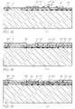
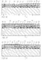
- FIG. 7provides a legend of the materials indicated in FIGS. 8 to 22 ;
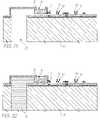
- FIG. 8 to FIG. 22illustrate sectional views of the manufacturing steps in one form of construction of an ink jet printhead nozzle.
- an inkjet printerhaving a series of ink ejection mechanisms wherein each ink ejection mechanism includes a paddle actuated by a coil actuator, the coil spring actuator having a unique cross section so as to provide for efficient actuation as a coiled thermal actuator.
- the ink ejection mechanism 1includes a chamber 2 having a rim 3 .
- the chamber 2is normally filled with ink which bulges out around a surface having a border along the edge of rim 3 , the ink being retained within the chamber 2 by means of surface tension around the rim 3 .
- a thermal actuator device 5outside of the chamber 2 is located a thermal actuator device 5 .
- the thermal actuator device 5is interconnected via a strut 6 through a hole 7 to a paddle device within the chamber 2 .
- the strut 6 and hole 7are treated so as to be hydrophobic.
- the hole 7is provided in a thin elongated form so that surface tension characteristics also assist in stopping any ink from flowing out of the hole 7 .
- the thermal actuator device 5comprises a first arm portion 9 which can be constructed from glass or other suitable non-conductive material.
- a second arm portion 10can be constructed from material such as titanium diboride which has a large Young's modulus or bending strength and hence, when a current is passed through the titanium diboride layer 10 , it expands with a predetermined coefficient of thermal expansion.
- the thin strip 10has a high Young's modulus or bending strength and therefore the thin strip 10 is able to bend the much thicker strip 9 which has a substantially lower Young's modulus.
- FIG. 2there is illustrated a cross-section of the arm through the line II-II of FIG. 1 illustrating the structure of the actuator device 5 .
- the actuator device 5includes two titanium diboride portions 10 a , 10 b forming a circuit around the coil in addition to the glass portion 9 which also provides for electrical isolation of the two arms, the arms being conductively joined at the strut end.
- FIGS. 3-5there will now be explaining the operation of the ink ejection mechanism 1 for the ejection of ink.
- the paddle 8begins to move towards the nozzle rim 3 resulting in a substantial increase in pressure in the area around the nozzle rim 3 .
- the actuatoris deactivated resulting in a general urge for the paddle 8 to return to its rest position.
- the meniscus 12has generally a concave shape and surface tension characteristics result in chamber refilling by means of in flow 13 from an ink supply channel etched through the wafer. The refilling is as a consequence of surface tension forces on the meniscus 12 . Eventually the meniscus returns to its quiescent state as illustrated in FIG. 3 .
- FIG. 6there is illustrated an exploded perspective view of a single ink ejection mechanism 1 illustrating the various material layers.
- the ink ejection mechanism 1can be formed as part of a large array of mechanisms forming a print head with multiple print heads being simultaneously formed on a silicon wafer 17 .
- the wafer 17is initially processed so as to incorporate a standard CMOS circuitry layer 18 which provides for the electrical interconnect for the control of the conductive portions of the actuator.
- the CMOS layer 18can be completed with a silicon nitride passivation layer so as to protect it from subsequent processing steps in addition to ink flows through channel 20 .
- the subsequent layerseg.
- MEMSmicro-electro mechanical systems
- sacrificial aluminum layersin addition to the deposit of the layers 10 constructed from titanium diboride the layer 9 constructed from glass material and the nozzle chamber proper 2 again constructed from titanium diboride.
- MEMSmicro-electro mechanical systems
- Each of these layerscan be built up in a sacrificial material such as aluminum which is subsequently etched away.
- an ink supply channel eg. 21can be etched through the wafer 17 .
- the etchingcan be by means of an isotropic crystallographic silicon etch or an isotropic dry etch.
- a dry etch system capable of high aspect ratio silicon trench etchingsuch as the Surface Technology Systems (STS) Advance Silicon Etch (ASE) system is recommended.
- STSSurface Technology Systems
- ASEAdvance Silicon Etch
- the nozzle arrangement 1can be attached to an ink supply apparatus for supplying ink to the reverse surface of the wafer 17 so that ink can flow into chamber 2 .
- the external surface of nozzle chamber 2 including rim 3in addition to the area surrounding slot 7 , can then be hydrophobically treated so as to reduce the possibility of any ink exiting slot 7 .
- the presently disclosed ink jet printing technologyis potentially suited to a wide range of printing system including: color and monochrome office printers, short run digital printers, high speed digital printers, offset press supplemental printers, low cost scanning printers high speed pagewidth printers, notebook computers with in-built pagewidth printers, portable color and monochrome printers, color and monochrome copiers, color and monochrome facsimile machines, combined printer, facsimile and copying machines, label printers, large format plotters, photograph copiers, printers for digital photographic “minilabs”, video printers, PHOTO CD (PHOTO CD is a registered trade mark of the Eastman Kodak Company) printers, portable printers for PDAs, wallpaper printers, indoor sign printers, billboard printers, fabric printers, camera printers and fault tolerant commercial printer arrays.
- PHOTO CDPHOTO CD is a registered trade mark of the Eastman Kodak Company
- the embodiments of the inventionuse an ink jet printer type device. Of course many different devices could be used. However presently popular ink jet printing technologies are unlikely to be suitable.
- thermal ink jetThe most significant problem with thermal ink jet is power consumption. This is approximately 100 times that required for high speed, and stems from the energy-inefficient means of drop ejection. This involves the rapid boiling of water to produce a vapor bubble which expels the ink. Water has a very high heat capacity, and must be superheated in thermal ink jet applications. This leads to an efficiency of around 0.02%, from electricity input to drop momentum (and increased surface area) out.
- piezoelectric ink jetThe most significant problem with piezoelectric ink jet is size and cost. Piezoelectric crystals have a very small deflection at reasonable drive voltages, and therefore require a large area for each nozzle. Also, each piezoelectric actuator must be connected to its drive circuit on a separate substrate. This is not a significant problem at the current limit of around 300 nozzles per print head, but is a major impediment to the fabrication of pagewidth print heads with 19,200 nozzles.
- the ink jet technologies usedmeet the stringent requirements of in-camera digital color printing and other high quality, high speed, low cost printing applications.
- new ink jet technologieshave been created.
- the target featuresinclude:
- ink jet designs shown hereare suitable for a wide range of digital printing systems, from battery powered one-time use digital cameras, through to desktop and network printers, and through to commercial printing systems
- the print headis designed to be a monolithic 0.5 micron CMOS chip with MEMS post processing.
- the print headis 100 mm long, with a width which depends upon the ink jet type.
- the smallest print head designedis IJ38, which is 0.35 mm wide, giving a chip area of 35 square mm.
- the print headseach contain 19,200 nozzles plus data and control circuitry.
- Inkis supplied to the back of the print head by injection molded plastic ink channels.
- the moldingrequires 50 micron features, which can be created using a lithographically micromachined insert in a standard injection molding tool.
- Inkflows through holes etched through the wafer to the nozzle chambers fabricated on the front surface of the wafer.
- the print headis connected to the camera circuitry by tape automated bonding.
- ink jet configurationscan readily be derived from these forty-five examples by substituting alternative configurations along one or more of the 11 axes.
- Most of the IJ01 to IJ45 examplescan be made into ink jet print heads with characteristics superior to any currently available ink jet technology.
- Suitable applications for the ink jet technologiesinclude: Home printers, Office network printers, Short run digital printers, Commercial print systems, Fabric printers, Pocket printers, Internet WWW printers, Video printers, Medical imaging, Wide format printers, Notebook PC printers, Fax machines, Industrial printing systems, Photocopiers, Photographic minilabs etc.
- Electro- An electric fieldis Low power Low maximum Seiko Epson, Usui strictive used to activate consumption strain (approx. et all JP 253401/96 electrostriction in Many ink types can 0.01%)
- IJ04 relaxor materialssuch be used Large area required as lead lanthanum Low thermal for actuator due to zirconate titanate expansion low strain (PLZT) or lead Electric field Response speed is magnesium niobate strength required marginal ( ⁇ 10 ⁇ s) (PMN).
- Perovskite ( ⁇ 1 ⁇ s) Actuatorsrequire a materials such as tin Relatively high large area modified lead longitudinal strain lanthanum zirconate High efficiency titanate (PLZSnT) Electric field exhibit large strains of strength of around 3 V/ ⁇ m up to 1% associated can be readily with the AFE to FE provided phase transition.
- Electrostatic Conductive platesare Low power Difficult to operate IJ02, IJ04 plates separated by a consumption electrostatic devices compressible or fluid Many ink types can in an aqueous dielectric (usually air). be used environment Upon application of a Fast operation The electrostatic voltage, the plates actuator will attract each other and normally need to be displace ink, causing separated from the drop ejection.
- the ink conductive platesmay Very large area be in a comb or required to achieve honeycomb structure, high forces or stacked to increase High voltage drive the surface area and transistors may be therefore the force.
- required Full pagewidth print headsare not competitive due to actuator size
- An electromagnet Low power Complex fabrication IJ07, IJ10 magnetdirectly attracts a consumption Permanent magnetic electro- permanent magnet
- Many ink typescan material such as magnetic displacing ink and be used Neodymium Iron causing drop ejection.
- the pagewidth print Copper metalization soft magnetic material headsshould be used for is in two parts, which long are normally held electromigration apart by a spring. lifetime and low When the solenoid is resistivity actuated, the two parts Electroplating is attract, displacing the required ink. High saturation flux density is required (2.0-2.1 T is achievable with CoNiFe [1]) Lorenz The Lorenz force Low power Force acts as a IJ06, IJ11, IJ13, force acting on a current consumption twisting motion IJ16 carrying wire in a Many ink types can Typically, only a magnetic field is be used quarter of the utilized.
- Pre-stressingmay be required Surface Ink under positive Low power Requires Silverbrook, EP tension pressure is held in a consumption supplementary force 0771 658 A2 and reduction nozzle by surface Simple construction to effect drop related patent tension.
- the surface No unusual separation applications tension of the inkis materials required in Requires special ink reduced below the fabrication surfactants bubble threshold, High efficiency Speed may be causing the ink to Easy extension from limited by surfactant egress from the single nozzles to properties nozzle.
- pagewidth print headsViscosity
- the ink viscosityis Simple construction Requires Silverbrook, EP reduction locally reduced to No unusual supplementary force 0771 658 A2 and select which drops are materials required in to effect drop related patent to be ejected.
- a fabrication separation applications viscosity reductioncan Easy extension from Requires special ink be achieved single nozzles to viscosity properties electrothermally with pagewidth print High speed is most inks, but special heads difficult to achieve inks can be engineered Requires oscillating for a 100:1 viscosity ink pressure reduction.
- a high temperature differencetypically 80 degrees
- Acoustic An acoustic waveis Can operate without Complex drive 1993 Hadimioglu et generated and a nozzle plate circuitry al, EUP 550,192 focussed upon the Complex fabrication 1993 Elrod et al, drop ejection region.
- Simple planar Corrosion IJ29, IJ30, IJ31, fabrication preventioncan be IJ32, IJ33, IJ34, Small chip area difficult IJ35, IJ36, IJ37, required for each Pigmented inks may IJ38, IJ39, IJ40, actuator be infeasible, as IJ41 Fast operation pigment particles High efficiency may jam the bend CMOS compatible actuator voltages and currents Standard MEMS processes can be used Easy extension from single nozzles to pagewidth print heads High CTE A material with a very High force can be Requires special IJ09, IJ17, IJ18, thermo- high coefficient of generated material (e.g.
- PTFEPTFE
- IJ20IJ21, IJ22
- elastic thermal expansionThree methods of Requires a PTFE IJ23, IJ24, IJ27, actuator (CTE) such as PTFE deposition are deposition process, IJ28, IJ29, IJ30, polytetrafluoroethylene under development: which is not yet IJ31, IJ42, IJ43, (PTFE) is used.
- CTEactuator
- PTFE deposition processIJ28, IJ29, IJ30
- polytetrafluoroethylene under developmentwhich is not yet IJ31, IJ42, IJ43, (PTFE) is used.
- CVDhigh CTE materials deposition
- fabsare usually non- spin coating
- PTFE deposition conductivea heater evaporation cannot be followed fabricated from a PTFE is a candidate with high conductive material is for low dielectric temperature (above incorporated.
- a 50 ⁇ m constant insulation 350° C.) processing long PTFE bend in ULSI Pigmented inksmay actuator with Very low power be infeasible, as polysilicon heater and consumption pigment particles 15 mW power input Many ink types can may jam the bend can provide 180 ⁇ N be used actuator force and 10 ⁇ m Simple planar deflection.
- Actuator fabrication motionsinclude: Small chip area Bend required for each Push actuator Buckle Fast operation Rotate High efficiency CMOS compatible voltages and currents Easy extension from single nozzles to pagewidth print heads Conductive A polymer with a high High force can be Requires special IJ24 polymer coefficient of thermal generated materials thermo- expansion (such as Very low power development (High elastic PTFE) is doped with consumption CTE conductive actuator conducting substances Many ink types can polymer) to increase its be used Requires a PTFE conductivity to about 3 Simple planar deposition process, orders of magnitude fabrication which is not yet below that of copper. Small chip area standard in ULSI The conducting required for each fabs polymer expands actuator PTFE deposition when resistively Fast operation cannot be followed heated.
- IJ24 polymer coefficient of thermal generated materials thermo- expansionsuch as Very low power development (High elastic PTFE) is doped with consumption CTE conductive actuator conducting substances Many ink types can polymer
- CMOS compatible temperature (above conducting dopants voltages and 350° C.) processinginclude: currents Evaporation and Carbon nanotubes Easy extension from CVD deposition Metal fibers single nozzles to techniques cannot Conductive polymers pagewidth print be used such as doped heads Pigmented inks may polythiophene be infeasible, as Carbon granules pigment particles may jam the bend actuator Shape A shape memory alloy High force is Fatigue limits IJ26 memory such as TiNi (also available (stresses maximum number alloy known as Nitinol - of hundreds of MPa) of cycles Nickel Titanium alloy Large strain is Low strain (1%) is developed at the Naval available (more than required to extend Ordnance Laboratory) 3%) fatigue resistance is thermally switched High corrosion Cycle rate limited between its weak resistance by heat removal martensitic state and Simple construction Requires unusual its high stiffness Easy extension from materials (TiNi) austenic state.
- IJ26 memorysuch as TiNi (also available (stresses maximum number alloy known as Nit
- the single nozzles to The latent heat of shape of the actuator pagewidth print transformationmust in its martensitic state heads be provided is deformed relative to Low voltage High current the austenic shape. operation operation
- the shape change Requires pre-causes ejection of a stressing to distort drop.
- the martensitic state Linear Linear magnetic Linear Magnetic Requires unusual IJ12 Magnetic actuatorsinclude the actuators can be semiconductor Actuator Linear Induction constructed with materials such as Actuator (LIA), Linear high thrust, long soft magnetic alloys Permanent Magnet travel, and high (e.g.
- LMSALinear planar require permanent Reluctance semiconductor magnetic materials Synchronous Actuator fabrication such as Neodymium (LRSA), Linear techniques iron boron (NdFeB) Switched Reluctance Long actuator travel Requires complex Actuator (LSRA), and is available multi-phase drive the Linear Stepper Medium force is circuitry Actuator (LSA). available High current Low voltage operation operation
- the drop velocityis less than method, but is IJ12, IJ14, IJ16, must have a sufficient 4 m/s related to the refill IJ20, IJ22, IJ23, velocity to overcome Can be efficient, method normally IJ24, IJ25, IJ26, the surface tension.
- Electrostatic The drops to be Very simple print Requires very high Silverbrook, EP pull printedare selected by head fabrication can electrostatic field 0771 658 A2 and on ink some manner (e.g. be used Electrostatic field related patent thermally induced The drop selection for small nozzle applications surface tension means does not need sizes is above air Tone-Jet reduction of to provide the breakdown pressurized ink). energy required to Electrostatic field Selected drops are separate the drop may attract dust separated from the ink from the nozzle in the nozzle by a strong electric field.
- the be achieved due to Requires ink ink pressureis pulsed reduced refill time pressure modulator at a multiple of the Drop timing can be Friction and wear drop ejection very accurate must be considered frequency.
- the actuator energy Stictionis possible can be very low Shuttered
- the actuatormoves a Actuators with Moving parts are IJ08, IJ15, IJ18, grill shutter to block ink small travel can be required IJ19 flow through a grill to used Requires ink the nozzle.
- the shutter Actuators with pressure modulator movementneed only small force can be Friction and wear be equal to the width used must be considered of the grill holes.
- the allowing higher Ink pressure phase applications acoustic actuatorselects which operating speed and amplitude must IJ08, IJ13, IJ15, stimulation) drops are to be fired
- the actuatorsmay be carefully IJ17, IJ18, IJ19, by selectively operate with much controlled IJ21 blocking or enabling lower energy Acoustic reflections nozzles.
- the ink Acoustic lensescan in the ink chamber pressure oscillation be used to focus the must be designed may be achieved by sound on the for vibrating the print nozzles head, or preferably by an actuator in the ink supply.
- Media The print headis Low power Precision assembly Silverbrook, EP proximity placed in close High accuracy required 0771 658 A2 and proximity to the print Simple print head Paper fibers may related patent medium.
- Transfer Dropsare printed to a High accuracy Bulky Silverbrook, EP roller transfer roller instead Wide range of print Expensive 0771 658 A2 and of straight to the print substrates can be Complex related patent medium.
- a transfer used construction applications rollercan also be used Ink can be dried on Tektronix hot melt for proximity drop the transfer roller piezoelectric ink jet separation. Any of the IJ series Electrostatic An electric field is Low power Field strength Silverbrook, EP used to accelerate Simple print head required for 0771 658 A2 and selected drops towards construction separation of small related patent the print medium.
- a magnetic fieldis Low power Requires magnetic Silverbrook, EP magnetic used to accelerate Simple print head ink 0771 658 A2 and field selected drops of construction Requires strong related patent magnetic ink towards magnetic field applications the print medium.
- Cross The print headis Does not require Requires external IJ06, IJ16 magnetic placed in a constant magnetic materials magnet field magnetic field.
- Lorenz force in a the print headmay be high, current carrying wire manufacturing resulting in is used to move the process electromigration actuator.
- Pulsed A pulsed magnetic Very low power Complex print head IJ10 magnetic field is used to operationis possible construction field cyclically attract a Small print head Magnetic materials paddle, which pushes size required in print on the ink.
- a small head actuatormoves a catch, which selectively prevents the paddle from moving.
- IJ18, IJ19, IJ20, actuatorThe expansion may be that the materials do IJ21, IJ22, IJ23, thermal, piezoelectric, not delaminate IJ24, IJ27, IJ29, magnetostrictive, or Residual bend IJ30, IJ31, IJ32, other mechanism.
- the resulting from high IJ33, IJ34, IJ35, bend actuatorconverts temperature or high IJ36, IJ37, IJ38, a high force low travel stress during IJ39, IJ42, IJ43, actuator mechanism to formation IJ44 high travel, lower force mechanism.
- Actuator A series of thin Increased travel Increased Some piezoelectric stack actuatorsare stacked. Reduced drive fabrication ink jets This can be voltage complexity IJ04 appropriate where Increased possibility actuators require high of short circuits due electric field strength, to pinholes such as electrostatic and piezoelectric actuators. Multiple Multiple smaller Increases the force Actuator forces may IJ12, IJ13, IJ18, actuators actuators are used available from an not add linearly, IJ20, IJ22, IJ28, simultaneously to actuator reducing efficiency IJ42, IJ43 move the ink. Each Multiple actuators actuator need provide can be positioned to only a portion of the control ink flow force required.
- Flexure A bend actuatorhas a Simple means of Care must be taken IJ10, IJ19, IJ33 bend small region near the increasing travel of not to exceed the actuator fixture point, which a bend actuator elastic limit in the flexes much more flexure area readily than the Stress distribution is remainder of the very uneven actuator.
- the actuator Difficult to flexingis effectively accurately model converted from an with finite element even coiling to an analysis angular bend, resulting in greater travel of the actuator tip.
- Catch The actuatorcontrols a Very low actuator Complex IJ10 small catch.
- the catch energy constructioneither enables or Very small actuator Requires external disables movement of size force an ink pusher that is Unsuitable for controlled in a bulk pigmented inks manner.
- Gears Gearscan be used to Low force, low Moving parts are IJ13 increase travel at the travel actuators can required expense of duration.
- actuator Circular gears, rack Can be fabricated cyclesare required and pinion, ratchets, using standard More complex drive and other gearing surface MEMS electronics methods can be used.
- Process Complex construction Friction, friction, and wearare possible Buckle
- a buckle platecan be Very fast movement Must stay within S. Hirata et al, “An plate used to change a slow achievable elastic limits of the Ink-jet Head Using actuator into a fast materials for long Diaphragm motion. It can also device life Microactuator”, convert a high force, High stresses Proc. IEEE MEMS, low travel actuator involved February 1996, pp 418-423.
- the volume of the Simple construction High energyis Hewlett-Packard expansion actuator changes, in the case of typically required to Thermal Ink jet pushing the ink in all thermal ink jet achieve volume Canon Bubblejet directions. expansion. This leads to thermal stress, cavitation, and kogation in thermal ink jet implementations Linear,
- the actuatormoves in Efficient coupling to High fabrication IJ01, IJ02, IJ04, normal to a direction normal to ink drops ejected complexity may be IJ07, IJ11, IJ14 chip the print head surface. normal to the required to achieve surface
- the nozzleis typically surface perpendicular in the line of motion movement.
- Rotary leversmay Device complexity IJ05, IJ08, IJ13, the rotation of some be used to increase May have friction at IJ28 element, such a grill or travel a pivot point impeller Small chip area requirements Bend The actuator bends A very small change Requires the 1970 Kyser et al when energized. This in dimensions can actuator to be made U.S. Pat. No. 3,946,398 may be due to be converted to a from at least two 1973 Stemme U.S. Pat. No. differential thermal large motion.
- the actuatoris Can be used with Requires careful IJ26, IJ32 normally bent, and shape memory balance of stresses straightens when alloys where the to ensure that the energized. austenic phase is quiescent bend is planar accurate Double
- the actuator bends in One actuatorcan be Difficult to make IJ36, IJ37, IJ38 bend one direction when used to power two the drops ejected by one element is nozzles. both bend directions energized, and bends Reduced chip size. identical. the other way when Not sensitive to A small efficiency another element is ambient temperature loss compared to energized. equivalent single bend actuators. Shear Energizing the Can increase the Not readily 1985 Fishbeck U.S. Pat. No.
- actuatorcauses a shear effective travel of applicable to other 4,584,590 motion in the actuator piezoelectric actuator material.
- actuators mechanismsRadial The actuator squeezes Relatively easy to High force required 1970 Zoltan U.S. Pat. No. constriction an ink reservoir, fabricate single Inefficient 3,683,212 forcing ink from a nozzles from glass Difficult to integrate constricted nozzle. tubing as with VLSI macroscopic processes structures Coil/ A coiled actuator Easy to fabricate as Difficult to fabricate IJ17, IJ21, IJ34, uncoil uncoils or coils more a planar VLSI for non-planar IJ35 tightly.
- Curl A set of actuatorscurl Relatively simple Relatively large IJ43 outwards outwards, pressurizing construction chip area ink in a chamber surrounding the actuators, and expelling ink from a nozzle in the chamber.
- Iris Multiple vanesenclose High efficiency High fabrication IJ22 a volume of ink. These Small chip area complexity simultaneously rotate, Not suitable for reducing the volume pigmented inks between the vanes.
- the inkis under a Drop selection and Requires a method Silverbrook, EP ink positive pressure, so separation forces (such as a nozzle 0771 658 A2 and pressure that in the quiescent can be reduced rim or effective related patent state some of the ink Fast refill time hydrophobizing, or applications drop already protrudes both) to prevent Possible operation from the nozzle.
- Inlet filteris located Additional Restricts refill rate IJ04, IJ12, IJ24, between the ink inlet advantage of ink May result in IJ27, IJ29, IJ30 and the nozzle filtration complex chamber.
- the filter Ink filtermay be construction has a multitude of fabricated with no small holes or slots, additional process restricting ink flow. steps The filter also removes particles which may block the nozzle.
- the ink inlet channel Design simplicityRestricts refill rate IJ02, IJ37, IJ44 compared to the nozzle chamber May result in a to nozzle has a substantially relatively large chip smaller cross section area than that of the nozzle, Only partially resulting in easier ink effective egress out of the nozzle than out of the inlet.
- Inlet A secondary actuatorIncreases speed of Requires separate IJ09 shutter controls the position of the ink-jet print refill actuator and a shutter, closing off head operation drive circuit the ink inlet when the main actuator is energized.
- the inletis The method avoids the Back-flow problem Requires careful IJ01, IJ03, IJ05, located problem of inlet back- is eliminated design to minimize IJ06, IJ07, IJ10, behind the flow by arranging the negative IJ11, IJ14, IJ16, ink- ink-pushing surface of pressure behind the IJ22, IJ23, IJ25, pushing the actuator between paddle IJ28, IJ31, IJ32, surface the inlet and the IJ33, IJ34, IJ35, nozzle.
- IJ36, IJ39, IJ40, IJ41 Part of the The actuator and a Significant Small increase in IJ07, IJ20, IJ26, actuator wall of the ink reductions in back- fabrication IJ38 moves to chamberare arranged flow can be complexity shut off so that the motion of achieved the inlet the actuator closes off Compact designs the inlet.
- the nozzle firingis IJ26, IJ27, IJ28, usually performed IJ29, IJ30, IJ31, during a special IJ32, IJ33, IJ34, clearing cycle, after IJ36, IJ37, IJ38, first moving the print IJ39, IJ40, IJ41, head to a cleaning IJ42, IJ43, IJ44, station.
- An ultrasonic waveis A high nozzle High IJ08, IJ13, IJ15, resonance applied to the ink clearing capability implementation cost IJ17, IJ18, IJ19, chamber.
- This waveis can be achieved if system does not IJ21 of an appropriate May be already include an amplitude and implemented at very acoustic actuator frequency to cause low cost in systems sufficient force at the which already nozzle to clear include acoustic blockages. This is actuators easiest to achieve if the ultrasonic wave is at a resonant frequency of the ink cavity.
- the plate alignmentis related patent has a post for every required applications nozzle. A post moves Moving parts are through each nozzle, required displacing dried ink. There is risk of damage to the nozzles Accurate fabrication is required Ink
- the pressure of the inkMay be effective Requires pressure May be used with pressure is temporarily where other pump or other all IJ series ink jets pulse increased so that ink methods cannot be pressure actuator streams from all of the used Expensive nozzles. This may be Wasteful of ink used in conjunction with actuator energizing.
- Print head A flexible ‘blade’is Effective for planar Difficult to use if Many ink jet wiper wiped across the print print head surfaces print head surface is systems head surface.
- the Low cost non-planar or very bladeis usually fragile fabricated from a Requires flexible polymer, e.g. mechanical parts rubber or synthetic Blade can wear out elastomer.
- a separate heateris Can be effective Fabrication Can be used with ink boiling provided at the nozzle where other nozzle complexity many IJ series ink heater although the normal clearing methods jets drop e-ection cannot be used mechanism does not Can be implemented require it.
- the heaters at no additional costdo not require in some ink jet individual drive configurations circuits, as many nozzles can be cleared simultaneously, and no imaging is required.
- Electroformed A nozzle plateis Fabrication High temperatures Hewlett Packard nickel separately fabricated simplicity and pressures are Thermal Ink jet from electroformed required to bond nickel, and bonded to nozzle plate the print head chip. Minimum thickness constraints Differential thermal expansion Laser Individual nozzle No masks required Each hole must be Canon Bubblejet ablated or holes are ablated by an Can be quite fast individually formed 1988 Sercel et al., drilled intense UV laser in a Some control over Special equipment SPIE, Vol. 998 polymer nozzle plate, which is nozzle profile is required Excimer Beam typically a polymer possible Slow where there Applications, pp.
- the nozzle plateis a High accuracy ( ⁇ 1 ⁇ m) Requires long etch IJ03, IJ05, IJ06, etched buried etch stop in the Monolithic times IJ07, IJ08, IJ09, through wafer.
- Nozzle Low cost Requires a support IJ10, IJ13, IJ14, substrate chambersare etched in No differential wafer IJ15, IJ16, IJ19, the front of the wafer, expansion IJ21, IJ23, IJ25, and the wafer is IJ26 thinned from the back side.
- Nozzlesare then etched in the etch stop layer.
- No nozzle Various methodshave No nozzles to Difficult to control Ricoh 1995 Sekiya plate been tried to eliminate become clogged drop position et al U.S. Pat. No. 5,412,413 the nozzles entirely, to accurately 1993 Hadimioglu et prevent nozzle Crosstalk problems al EUP 550,192 clogging.
- Elrod et alinclude thermal bubble EUP 572,220 mechanisms and acoustic lens mechanisms Trough Each drop ejector has Reduced Drop firing IJ35 a trough through manufacturing direction is sensitive which a paddle moves. complexity to wicking. There is no nozzle Monolithic plate. Nozzle slit The elimination of No nozzles to Difficult to control 1989 Saito et al instead of nozzle holes and become clogged drop position U.S. Pat. No. 4,799,068 individual replacement by a slit accurately nozzles encompassing many Crosstalk problems actuator positions reduces nozzle clogging, but increases crosstalk due to ink surface waves
- Edge Ink flowis along the Simple construction Nozzles limited to Canon Bubblejet (‘edge surface of the chip, No silicon etching edge 1979 Endo et al GB shooter’) and ink drops are required High resolution is patent 2,007,162 ejected from the chip Good heat sinking difficult Xerox heater-in-pit edge. via substrate Fast color printing 1990 Hawkins et al Mechanically strong requires one print U.S. Pat. No.
- Cockles paper 0771 658 A2 and Modern ink dyeshave related patent high water-fastness, applications light fastness Aqueous, Water based ink which Environmentally Slow drying IJ02, IJ04, IJ21, pigment typically contains: friendly Corrosive IJ26, IJ27, IJ30 water, pigment, No odor Pigment may clog Silverbrook, EP surfactant, humectant, Reduced bleed nozzles 0771 658 A2 and and biocide.
- Reduced wicking Pigmentmay clog related patent Pigments have an Reduced actuator applications advantage in reduced strikethrough mechanisms Piezoelectric ink- bleed, wicking and Cockles paper jets strikethrough.
- Methyl MEKis a highly Very fast drying Odorous All IJ series ink jets Ethyl volatile solvent used Prints on various Flammable Ketone for industrial printing substrates such as (MEK) on difficult surfaces metals and plastics such as aluminum cans.
- Alcohol Alcohol based inksFast drying Slight odor All IJ series ink jets (ethanol, can be used where the Operates at sub- Flammable 2-butanol, printer must operate at freezing and temperatures below temperatures others) the freezing point of Reduced paper water.
- An example of cockle thisis in-camera Low cost consumer photographic printing.
- the inkis solid at No drying time- ink High viscosity Tektronix hot melt change room temperature, and instantly freezes on Printed ink typically piezoelectric ink jets (hot melt) is melted in the print the print medium has a ‘waxy’ feel 1989 Nowak U.S. Pat. No. head before jetting. Almost any print Printed pages may 4,820,346 Hot melt inks are medium can be used ‘block’ All IJ series ink jets usually wax based, No paper cockle Ink temperature with a melting point occurs may be above the around 80° C.
- Oil Oil based inksare High solubility High viscosity: this All IJ series ink jets extensively used in medium for some is a significant offset printing. They dyes limitation for use in have advantages in Does not cockle ink jets, which improved paper usually require a characteristics on Does not wick low viscosity. Some paper (especially no through paper short chain and wicking or cockle). multi-branched oils Oil soluble dies and have a sufficiently pigments are required. low viscosity.
- a microemulsionis a Stops ink bleed Viscosity higher All IJ series ink jets stable, self forming High dye solubility than water emulsion of oil, water, Water, oil, and Cost is slightly and surfactant.
- the amphiphilic soluble higher than water characteristic drop size diescan be used based ink is less than 100 nm, Can stabilize High surfactant and is determined by pigment concentration the preferred curvature suspensions required (around of the surfactant. 5%)
Landscapes
- Engineering & Computer Science (AREA)
- Manufacturing & Machinery (AREA)
- Physics & Mathematics (AREA)
- Theoretical Computer Science (AREA)
- General Physics & Mathematics (AREA)
- Computer Hardware Design (AREA)
- Computer Security & Cryptography (AREA)
- Chemical & Material Sciences (AREA)
- General Engineering & Computer Science (AREA)
- Software Systems (AREA)
- Health & Medical Sciences (AREA)
- Electromagnetism (AREA)
- General Health & Medical Sciences (AREA)
- Toxicology (AREA)
- Artificial Intelligence (AREA)
- Computer Vision & Pattern Recognition (AREA)
- Nanotechnology (AREA)
- Signal Processing (AREA)
- Microelectronics & Electronic Packaging (AREA)
- Composite Materials (AREA)
- Condensed Matter Physics & Semiconductors (AREA)
- Materials Engineering (AREA)
- Crystallography & Structural Chemistry (AREA)
- Multimedia (AREA)
- Particle Formation And Scattering Control In Inkjet Printers (AREA)
Abstract
Description
This application is a continuation of U.S. application Ser. No. 11/056,146 filed Feb. 14, 2005, now issued U.S. Pat. No. 7,390,421, which is a continuation of U.S. application Ser. No. 09/113,076 filed Jul. 10, 1998, now issued U.S. Pat. No. 6,855,264, the entire contents of which are herein incorporated by reference.
The following Australian provisional patent applications are hereby incorporated by cross-reference. For the purposes of location and identification, US patent applications identified by their US patent application serial numbers (USSN) are listed alongside the Australian applications from which the US patent applications claim the right of priority.
| CROSS- | ||
| REFERENCED | ||
| AUSTRALIAN | US PATENT/PATENT | |
| PROVISIONAL | APPLICATION (CLAIMING | |
| PATENT | RIGHT OF PRIORITY | |
| APPLICATION | FROM AUSTRALIAN | |
| NO. | PROVISIONAL APPLICATION) | DOCKET NO. |
| PO7991 | 6,750,901 | ART01US |
| PO8505 | 6,476,863 | ART02US |
| PO7988 | 6,788,336 | ART03US |
| PO9395 | 6,322,181 | ART04US |
| PO8017 | 6,597,817 | ART06US |
| PO8014 | 6,227,648 | ART07US |
| PO8025 | 6,727,948 | ART08US |
| PO8032 | 6,690,419 | ART09US |
| PO7999 | 6,727,951 | ART10US |
| PO8030 | 6,196,541 | ART13US |
| PO7997 | 6,195,150 | ART15US |
| PO7979 | 6,362,868 | ART16US |
| PO7978 | 6,831,681 | ART18US |
| PO7982 | 6,431,669 | ART19US |
| PO7989 | 6,362,869 | ART20US |
| PO8019 | 6,472,052 | ART21US |
| PO7980 | 6,356,715 | ART22US |
| PO8018 | 6,894,694 | ART24US |
| PO7938 | 6,636,216 | ART25US |
| PO8016 | 6,366,693 | ART26US |
| PO8024 | 6,329,990 | ART27US |
| PO7939 | 6,459,495 | ART29US |
| PO8501 | 6,137,500 | ART30US |
| PO8500 | 6,690,416 | ART31US |
| PO7987 | 7,050,143 | ART32US |
| PO8022 | 6,398,328 | ART33US |
| PO8497 | 7,110,024 | ART34US |
| PO8020 | 6,431,704 | ART38US |
| PO8504 | 6,879,341 | ART42US |
| PO8000 | 6,415,054 | ART43US |
| PO7934 | 6,665,454 | ART45US |
| PO7990 | 6,542,645 | ART46US |
| PO8499 | 6,486,886 | ART47US |
| PO8502 | 6,381,361 | ART48US |
| PO7981 | 6,317,192 | ART50US |
| PO7986 | 6,850,274 | ART51US |
| PO7983 | 09/113,054 | ART52US |
| PO8026 | 6,646,757 | ART53US |
| PO8028 | 6,624,848 | ART56US |
| PO9394 | 6,357,135 | ART57US |
| PO9397 | 6,271,931 | ART59US |
| PO9398 | 6,353,772 | ART60US |
| PO9399 | 6,106,147 | ART61US |
| PO9400 | 6,665,008 | ART62US |
| PO9401 | 6,304,291 | ART63US |
| PO9403 | 6,305,770 | ART65US |
| PO9405 | 6,289,262 | ART66US |
| PP0959 | 6,315,200 | ART68US |
| PP1397 | 6,217,165 | ART69US |
| PP2370 | 6,786,420 | DOT01US |
| PO8003 | 6,350,023 | Fluid01US |
| PO8005 | 6,318,849 | Fluid02US |
| PO8066 | 6,227,652 | IJ01US |
| PO8072 | 6,213,588 | IJ02US |
| PO8040 | 6,213,589 | IJ03US |
| PO8071 | 6,231,163 | IJ04US |
| PO8047 | 6,247,795 | IJ05US |
| PO8035 | 6,394,581 | IJ06US |
| PO8044 | 6,244,691 | IJ07US |
| PO8063 | 6,257,704 | IJ08US |
| PO8057 | 6,416,168 | IJ09US |
| PO8056 | 6,220,694 | IJ10US |
| PO8069 | 6,257,705 | IJ11US |
| PO8049 | 6,247,794 | IJ12US |
| PO8036 | 6,234,610 | IJ13US |
| PO8048 | 6,247,793 | IJ14US |
| PO8070 | 6,264,306 | IJ15US |
| PO8067 | 6,241,342 | IJ16US |
| PO8001 | 6,247,792 | IJ17US |
| PO8038 | 6,264,307 | IJ18US |
| PO8033 | 6,254,220 | IJ19US |
| PO8002 | 6,234,611 | IJ20US |
| PO8068 | 6,302,528 | IJ21US |
| PO8062 | 6,283,582 | IJ22US |
| PO8034 | 6,239,821 | IJ23US |
| PO8039 | 6,338,547 | IJ24US |
| PO8041 | 6,247,796 | IJ25US |
| PO8004 | 6,557,977 | IJ26US |
| PO8037 | 6,390,603 | IJ27US |
| PO8043 | 6,362,843 | IJ28US |
| PO8042 | 6,293,653 | IJ29US |
| PO8064 | 6,312,107 | IJ30US |
| PO9389 | 6,227,653 | IJ31US |
| PO9391 | 6,234,609 | IJ32US |
| PP0888 | 6,238,040 | IJ33US |
| PP0891 | 6,188,415 | IJ34US |
| PP0890 | 6,227,654 | IJ35US |
| PP0873 | 6,209,989 | IJ36US |
| PP0993 | 6,247,791 | IJ37US |
| PP0890 | 6,336,710 | IJ38US |
| PP1398 | 6,217,153 | IJ39US |
| PP2592 | 6,416,167 | IJ40US |
| PP2593 | 6,243,113 | IJ41US |
| PP3991 | 6,283,581 | IJ42US |
| PP3987 | 6,247,790 | IJ43US |
| PP3985 | 6,260,953 | IJ44US |
| PP3983 | 6,267,469 | IJ45US |
| PO7935 | 6,224,780 | IJM01US |
| PO7936 | 6,235,212 | IJM02US |
| PO7937 | 6,280,643 | IJM03US |
| PO8061 | 6,284,147 | IJM04US |
| PO8054 | 6,214,244 | IJM05US |
| PO8065 | 6,071,750 | IJM06US |
| PO8055 | 6,267,905 | IJM07US |
| PO8053 | 6,251,298 | IJM08US |
| PO8078 | 6,258,285 | IJM09US |
| PO7933 | 6,225,138 | IJM10US |
| PO7950 | 6,241,904 | IJM11US |
| PO7949 | 6,299,786 | IJM12US |
| PO8060 | 6,866,789 | IJM13US |
| PO8059 | 6,231,773 | IJM14US |
| PO8073 | 6,190,931 | IJM15US |
| PO8076 | 6,248,249 | IJM16US |
| PO8075 | 6,290,862 | IJM17US |
| PO8079 | 6,241,906 | IJM18US |
| PO8050 | 6,565,762 | IJM19US |
| PO8052 | 6,241,905 | IJM20US |
| PO7948 | 6,451,216 | IJM21US |
| PO7951 | 6,231,772 | IJM22US |
| PO8074 | 6,274,056 | IJM23US |
| PO7941 | 6,290,861 | IJM24US |
| PO8077 | 6,248,248 | IJM25US |
| PO8058 | 6,306,671 | IJM26US |
| PO8051 | 6,331,258 | IJM27US |
| PO8045 | 6,110,754 | IJM28US |
| PO7952 | 6,294,101 | IJM29US |
| PO8046 | 6,416,679 | IJM30US |
| PO9390 | 6,264,849 | IJM31US |
| PO9392 | 6,254,793 | IJM32US |
| PP0889 | 6,235,211 | IJM35US |
| PP0887 | 6,491,833 | IJM36US |
| PP0882 | 6,264,850 | IJM37US |
| PP0874 | 6,258,284 | IJM38US |
| PP1396 | 6,312,615 | IJM39US |
| PP3989 | 6,228,668 | IJM40US |
| PP2591 | 6,180,427 | IJM41US |
| PP3990 | 6,171,875 | IJM42US |
| PP3986 | 6,267,904 | IJM43US |
| PP3984 | 6,245,247 | IJM44US |
| PP3982 | 6,315,914 | IJM45US |
| PP0895 | 6,231,148 | IR01US |
| PP0869 | 6,293,658 | IR04US |
| PP0887 | 6,614,560 | IR05US |
| PP0885 | 6,238,033 | IR06US |
| PP0884 | 6,312,070 | IR10US |
| PP0886 | 6,238,111 | IR12US |
| PP0877 | 6,378,970 | IR16US |
| PP0878 | 6,196,739 | IR17US |
| PP0883 | 6,270,182 | IR19US |
| PP0880 | 6,152,619 | IR20US |
| PO8006 | 6,087,638 | MEMS02US |
| PO8007 | 6,340,222 | MEMS03US |
| PO8010 | 6,041,600 | MEMS05US |
| PO8011 | 6,299,300 | MEMS06US |
| PO7947 | 6,067,797 | MEMS07US |
| PO7944 | 6,286,935 | MEMS09US |
| PO7946 | 6,044,646 | MEMS10US |
| PP0894 | 6,382,769 | MEMS13US |
Not applicable.
The present invention relates to the field of inkjet printing and, in particular, discloses a method of manufacture of an ink jet printer having a thermal actuator comprising an external coil spring.
Many ink jet printing mechanisms are known. Unfortunately, in mass production techniques, the production of ink jet heads is quite difficult. For example, often, the orifice or nozzle plate is constructed separately from the ink supply and ink ejection mechanism and bonded to the mechanism at a later stage (Hewlett-Packard Journal, Vol. 36no 5, pp 33-37 (1985)). These separate material processing steps required in handling such precision devices often add a substantial expense in manufacturing.
Additionally, side shooting ink jet technologies (U.S. Pat. No. 4,899,181) are often used but again, this limits the amount of mass production throughput given any particular capital investment.
Additionally, more esoteric techniques are also often utilized. These can include electroforming of nickel stage (Hewlett-Packard Journal, Vol. 36no 5, pp 33-37 (1985)), electro-discharge machining, laser ablation (U.S. Pat. No. 5,208,604), micro-punching, etc.
The utilization of the above techniques is likely to add substantial expense to the mass production of ink jet print heads and therefore add substantially to their final cost.
It would therefore be desirable if an efficient system for the mass production of ink jet print heads could be developed.
It is an object of the present invention to provide for a method of manufacture of an ink jet printer having a thermal actuator comprising an external coil spring.
In accordance with a first aspect of the present invention, there is provided a method of manufacture of an ink jet printer having a thermal actuator comprising an external coil spring wherein an array of nozzles are formed on a substrate utilizing planar monolithic deposition, lithographic and etching processes.
Multiple ink jet heads are preferably formed simultaneously on a single planar substrate which can comprise a silicon wafer.
The print heads are preferably formed utilizing standard vlsi/ulsi processing with integrated drive electronics are preferably formed on the same substrate. The integrated drive electronics may be formed utilizing a CMOS fabrication process.
Ink can be ejected from the substrate substantially normal to the substrate.
In accordance with a further aspect of the present invention, there is provided a method of manufacture of a thermally actuated ink jet printer comprising a series of nozzle chambers which ejects ink via the utilization of a thermal actuator device, comprising the steps of: (a) initially providing a silicon wafer having a circuitry wafer layer including the electrical circuitry necessary for the operation of the thermal actuators on demand; (b) etching an ink inlet aperture in the circuitry wafer layer; (c) depositing and etching a first sacrificial layer on top of the silicon and circuitry wafer layer and etching the first sacrificial layer in an area defining a first portion of a nozzle chamber wall, a thermal actuator anchor and a thermal actuator end point; (d) depositing and etching a first inert material layer in defining a first actuator path starting at the thermal actuator anchor; (e) depositing and etching a first conductive material layer adjacent the first actuator path and attached to the first inert material layer; (f) depositing and etching a non-conductive layer over the first conductive material layer, the etching including etching predetermined vias for interconnection of the first conductive material layer with a second conductive material layer; (g) depositing and etching a second inert material layer on top of the first inert material layer; (h) depositing and etching a second conductive material layer on top of the non-conductive layer having a conductive interconnect to the first conductive material layer; (i) depositing and etching a series of inert material layers and sacrificial layers to form a nozzle chamber including an ink ejection hole and a nozzle chamber paddle attached to one of the inert material layers or the conductive layers at the thermal actuator end point; (j) etching an ink supply channel through the wafer to the nozzle chamber; and (k) etching away the sacrificial layers.
The conductive material layers are preferably formed from a material having a high Young's modulus such as titanium nitride. The first and second inert material layers can comprise substantially glass. The first actuator path can comprise substantially a coil.
The steps are preferably also utilized to simultaneously separate the wafer into separate printheads.
Notwithstanding any other forms which may fall within the scope of the present invention, preferred forms of the invention will now be described, by way of example only, with reference to the accompanying drawings in which:
In the preferred embodiment, there is provided an inkjet printer having a series of ink ejection mechanisms wherein each ink ejection mechanism includes a paddle actuated by a coil actuator, the coil spring actuator having a unique cross section so as to provide for efficient actuation as a coiled thermal actuator.
Turning initially toFIG. 1 , there is illustrated a singleink ejection mechanism 1 constructed in accordance with the principles of the preferred embodiment. Theink ejection mechanism 1 includes achamber 2 having arim 3. Thechamber 2 is normally filled with ink which bulges out around a surface having a border along the edge ofrim 3, the ink being retained within thechamber 2 by means of surface tension around therim 3. Outside of thechamber 2 is located athermal actuator device 5. Thethermal actuator device 5 is interconnected via astrut 6 through ahole 7 to a paddle device within thechamber 2. Thestrut 6 andhole 7 are treated so as to be hydrophobic. Further, thehole 7 is provided in a thin elongated form so that surface tension characteristics also assist in stopping any ink from flowing out of thehole 7.
Thethermal actuator device 5 comprises afirst arm portion 9 which can be constructed from glass or other suitable non-conductive material. Asecond arm portion 10 can be constructed from material such as titanium diboride which has a large Young's modulus or bending strength and hence, when a current is passed through the titaniumdiboride layer 10, it expands with a predetermined coefficient of thermal expansion. Thethin strip 10 has a high Young's modulus or bending strength and therefore thethin strip 10 is able to bend the muchthicker strip 9 which has a substantially lower Young's modulus.
Turning toFIG. 2 , there is illustrated a cross-section of the arm through the line II-II ofFIG. 1 illustrating the structure of theactuator device 5. As described previously, theactuator device 5 includes two titaniumdiboride portions 10a,10bforming a circuit around the coil in addition to theglass portion 9 which also provides for electrical isolation of the two arms, the arms being conductively joined at the strut end.
Turning now toFIGS. 3-5 , there will now be explaining the operation of theink ejection mechanism 1 for the ejection of ink. Initially, before thepaddle 8 has started moving, the situation is as illustrated inFIG. 3 with thenozzle chamber 2 being filled with ink and having a slightly bulgingmeniscus 12. Upon actuation of the actuator mechanism, thepaddle 8 begins to move towards thenozzle rim 3 resulting in a substantial increase in pressure in the area around thenozzle rim 3. This in turn results in the situation as illustrated inFIG. 4 wherein the meniscus begins to significantly bulge as a result of the increases in pressure. Subsequently, the actuator is deactivated resulting in a general urge for thepaddle 8 to return to its rest position. This results in the ink being sucked back into thechamber 2 which in turn results in the meniscus necking and breaking off into ameniscus 12 andink drop 14, thedrop 14 proceeding to a paper or film medium (not shown) for marking. Themeniscus 12 has generally a concave shape and surface tension characteristics result in chamber refilling by means of inflow 13 from an ink supply channel etched through the wafer. The refilling is as a consequence of surface tension forces on themeniscus 12. Eventually the meniscus returns to its quiescent state as illustrated inFIG. 3 .
Turning now toFIG. 6 , there is illustrated an exploded perspective view of a singleink ejection mechanism 1 illustrating the various material layers. Theink ejection mechanism 1 can be formed as part of a large array of mechanisms forming a print head with multiple print heads being simultaneously formed on asilicon wafer 17. Thewafer 17 is initially processed so as to incorporate a standardCMOS circuitry layer 18 which provides for the electrical interconnect for the control of the conductive portions of the actuator. TheCMOS layer 18 can be completed with a silicon nitride passivation layer so as to protect it from subsequent processing steps in addition to ink flows through channel20. The subsequent layers eg.9,10 and2 can be deposited utilizing standard micro-electro mechanical systems (MEMS) construction techniques including the deposit of sacrificial aluminum layers in addition to the deposit of thelayers 10 constructed from titanium diboride thelayer 9 constructed from glass material and the nozzle chamber proper2 again constructed from titanium diboride. Each of these layers can be built up in a sacrificial material such as aluminum which is subsequently etched away. Further, an ink supply channel eg.21 can be etched through thewafer 17. The etching can be by means of an isotropic crystallographic silicon etch or an isotropic dry etch. A dry etch system capable of high aspect ratio silicon trench etching such as the Surface Technology Systems (STS) Advance Silicon Etch (ASE) system is recommended.
Subsequent to construction of thenozzle arrangement 1, it can be attached to an ink supply apparatus for supplying ink to the reverse surface of thewafer 17 so that ink can flow intochamber 2.
The external surface ofnozzle chamber 2 includingrim 3, in addition to thearea surrounding slot 7, can then be hydrophobically treated so as to reduce the possibility of anyink exiting slot 7.
One form of detailed manufacturing process which can be used to fabricate monolithic ink jet print heads operating in accordance with the principles taught by the present embodiment can proceed utilizing the following steps:
- 1. Using a double sided
polished wafer 17, Complete drive transistors, data distribution, and timing circuits using a 0.5 micron, one poly, 2 metal CMOS process to formlayer 18. This step is shown inFIG. 8 . For clarity, these diagrams may not be to scale, and may not represent a cross section though any single plane of the nozzle.FIG. 7 is a key to representations of various materials in these manufacturing diagrams, and those of other cross referenced ink jet configurations. - 2.
Etch oxide layer 18 down to silicon oraluminum using Mask 1. This mask defines the ink inlet, the heater contact vias, and the edges of the print heads chip. This step is shown inFIG. 9 . - 3.
Deposit 1 micron of sacrificial material30 (e.g. aluminum). - 4. Etch the
sacrificial layer 30 usingMask 2, defining the nozzle chamber wall and the actuator anchor point. This step is shown inFIG. 10 . - 5.
Deposit 1 micron ofglass 31. - 6. Etch the
glass 31 usingMask 3, which defines the lower layer of the actuator loop. - 7.
Deposit 1 micron ofheater material 32, for example titanium nitride (TiN) or titanium diboride (TiB2). Planarize using CMP.Steps 5 to 7 form a ‘damascene’ process. This step is shown inFIG. 11 . - 8. Deposit 0.1 micron of silicon nitride (not shown).
- 9.
Deposit 1 micron ofglass 33. - 10. Etch the
glass 33 using Mask4, which defines the upper layer of the actuator loop. - 11. Etch the silicon
nitride using Mask 5, which defines the vias connecting the upper layer of the actuator loop to the lower layer of the actuator loop. - 12.
Deposit 1 micron of thesame heater material 34 as instep 7heater material 32. Planarize using CMP.Steps 8 to 12 form a ‘dual damascene’ process. This step is shown inFIG. 12 . - 13. Etch the glass down to the
sacrificial layer 30 usingMask 6, which defines the actuator and the nozzle chamber wall, with the exception of the nozzle chamber actuator slot. This step is shown inFIG. 13 . - 14. Wafer probe. All electrical connections are complete at this point, bond pads are accessible, and the chips are not yet separated.
- 15.
Deposit 3 microns ofsacrificial material 35. - 16. Etch the
sacrificial layer 35 down toglass using Mask 7, which defines the nozzle chamber wall, with the exception of the nozzle chamber actuator slot. This step is shown inFIG. 14 . - 17.
Deposit 1 micron ofPECVD glass 36 and planarize down to thesacrificial layer 35 using CMP. This step is shown inFIG. 15 . - 18.
Deposit 5 microns ofsacrificial material 37. - 19. Etch the
sacrificial material 37 down toglass using Mask 8. This mask defines the nozzle chamber wall and the paddle. This step is shown inFIG. 16 . - 20.
Deposit 3 microns ofPECVD glass 38 and planarize down to thesacrificial layer 37 using CMP. - 21.
Deposit 1 micron ofsacrificial material 39. - 22. Etch the
sacrificial material 39 down toglass using Mask 9. This mask defines the nozzle chamber wall. This step is shown inFIG. 17 . - 23.
Deposit 3 microns ofPECVD glass 40. - 24. Etch to a depth of (approx.) 1
micron using Mask 10. This mask defines thenozzle rim 3. This step is shown inFIG. 18 . - 25. Etch down to the
sacrificial layer 39 using Mask11. This mask defines the roof of the nozzle chamber, and the nozzle itself. This step is shown inFIG. 19 . - 26. Back-etch completely through the silicon wafer (with, for example, an ASE Advanced Silicon Etcher from Surface Technology Systems) using
Mask 12. This mask defines theink inlets 21 which are etched through the wafer. The wafer is also diced by this etch. This step is shown inFIG. 20 . - 27. Etch the
sacrificial material FIG. 21 . - 28. Mount the print heads in their packaging, which may be a molded plastic former incorporating ink channels which supply the appropriate color ink to the ink inlets at the back of the wafer.
- 29. Connect the print heads to their interconnect systems. For a low profile connection with minimum disruption of airflow, TAB may be used. Wire bonding may also be used if the printer is to be operated with sufficient clearance to the paper.
- 30. Hydrophobize the front surface of the print heads.
- 31. Fill the completed print heads with
ink 41 and test them. A filled nozzle is shown inFIG. 22 .
The presently disclosed ink jet printing technology is potentially suited to a wide range of printing system including: color and monochrome office printers, short run digital printers, high speed digital printers, offset press supplemental printers, low cost scanning printers high speed pagewidth printers, notebook computers with in-built pagewidth printers, portable color and monochrome printers, color and monochrome copiers, color and monochrome facsimile machines, combined printer, facsimile and copying machines, label printers, large format plotters, photograph copiers, printers for digital photographic “minilabs”, video printers, PHOTO CD (PHOTO CD is a registered trade mark of the Eastman Kodak Company) printers, portable printers for PDAs, wallpaper printers, indoor sign printers, billboard printers, fabric printers, camera printers and fault tolerant commercial printer arrays.
It would be appreciated by a person skilled in the art that numerous variations and/or modifications may be made to the present invention as shown in the specific embodiments without departing from the spirit or scope of the invention as broadly described. The present embodiments are, therefore, to be considered in all respects to be illustrative and not restrictive.
Ink Jet Technologies
The embodiments of the invention use an ink jet printer type device. Of course many different devices could be used. However presently popular ink jet printing technologies are unlikely to be suitable.
The most significant problem with thermal ink jet is power consumption. This is approximately 100 times that required for high speed, and stems from the energy-inefficient means of drop ejection. This involves the rapid boiling of water to produce a vapor bubble which expels the ink. Water has a very high heat capacity, and must be superheated in thermal ink jet applications. This leads to an efficiency of around 0.02%, from electricity input to drop momentum (and increased surface area) out.
The most significant problem with piezoelectric ink jet is size and cost. Piezoelectric crystals have a very small deflection at reasonable drive voltages, and therefore require a large area for each nozzle. Also, each piezoelectric actuator must be connected to its drive circuit on a separate substrate. This is not a significant problem at the current limit of around 300 nozzles per print head, but is a major impediment to the fabrication of pagewidth print heads with 19,200 nozzles.
Ideally, the ink jet technologies used meet the stringent requirements of in-camera digital color printing and other high quality, high speed, low cost printing applications. To meet the requirements of digital photography, new ink jet technologies have been created. The target features include:
low power (less than 10 Watts)
high resolution capability (1,600 dpi or more)
photographic quality output
low manufacturing cost
small size (pagewidth times minimum cross section)
high speed (<2 seconds per page).
All of these features can be met or exceeded by the ink jet systems described below with differing levels of difficulty. Forty-five different ink jet technologies have been developed by the Assignee to give a wide range of choices for high volume manufacture. These technologies form part of separate applications assigned to the present Assignee as set out in the table above under the heading Cross References to Related Applications.
The ink jet designs shown here are suitable for a wide range of digital printing systems, from battery powered one-time use digital cameras, through to desktop and network printers, and through to commercial printing systems
For ease of manufacture using standard process equipment, the print head is designed to be a monolithic 0.5 micron CMOS chip with MEMS post processing. For color photographic applications, the print head is 100 mm long, with a width which depends upon the ink jet type. The smallest print head designed is IJ38, which is 0.35 mm wide, giving a chip area of 35 square mm. The print heads each contain 19,200 nozzles plus data and control circuitry.
Ink is supplied to the back of the print head by injection molded plastic ink channels. The molding requires 50 micron features, which can be created using a lithographically micromachined insert in a standard injection molding tool. Ink flows through holes etched through the wafer to the nozzle chambers fabricated on the front surface of the wafer. The print head is connected to the camera circuitry by tape automated bonding.
Tables of Drop-on-Demand Ink Jets
Eleven important characteristics of the fundamental operation of individual ink jet nozzles have been identified. These characteristics are largely orthogonal, and so can be elucidated as an eleven dimensional matrix. Most of the eleven axes of this matrix include entries developed by the present assignee.
The following tables form the axes of an eleven dimensional table of ink jet types.
Actuator mechanism (18 types)
Basic operation mode (7 types)
Auxiliary mechanism (8 types)
Actuator amplification or modification method (17 types)
Actuator motion (19 types)
Nozzle refill method (4 types)
Method of restricting back-flow through inlet (10 types)
Nozzle clearing method (9 types)
Nozzle plate construction (9 types)
Drop ejection direction (5 types)
Ink type (7 types)
The complete eleven dimensional table represented by these axes contains 36.9 billion possible configurations of ink jet nozzle. While not all of the possible combinations result in a viable ink jet technology, many million configurations are viable. It is clearly impractical to elucidate all of the possible configurations. Instead, certain ink jet types have been investigated in detail. These are designated IJ01 to IJ45 which matches the docket numbers in the in the table under the heading Cross References to Related Applications.
Other ink jet configurations can readily be derived from these forty-five examples by substituting alternative configurations along one or more of the 11 axes. Most of the IJ01 to IJ45 examples can be made into ink jet print heads with characteristics superior to any currently available ink jet technology.
Where there are prior art examples known to the inventor, one or more of these examples are listed in the examples column of the tables below. The IJ01 to IJ45 series are also listed in the examples column. In some cases, a printer may be listed more than once in a table, where it shares characteristics with more than one entry.
Suitable applications for the ink jet technologies include: Home printers, Office network printers, Short run digital printers, Commercial print systems, Fabric printers, Pocket printers, Internet WWW printers, Video printers, Medical imaging, Wide format printers, Notebook PC printers, Fax machines, Industrial printing systems, Photocopiers, Photographic minilabs etc.
The information associated with the aforementioned 11 dimensional matrix are set out in the following tables.
| ACTUATOR MECHANISM (APPLIED ONLY TO SELECTED INK DROPS) |
| Description | Advantages | Disadvantages | Examples | ||
| Thermal | An electrothermal | Large force | High power | Canon Bubblejet |
| bubble | heater heats the ink to | generated | Ink carrier limited to | 1979 Endo et al GB |
| above boiling point, | Simple construction | water | patent 2,007,162 | |
| transferring significant | No moving parts | Low efficiency | Xerox heater-in-pit | |
| heat to the aqueous | Fast operation | High temperatures | 1990 Hawkins et al | |
| ink. A bubble | Small chip area | required | U.S. Pat. No. 4,899,181 | |
| nucleates and quickly | required for actuator | High mechanical | Hewlett-Packard TIJ | |
| forms, expelling the | stress | 1982 Vaught et al | ||
| ink. | Unusual materials | U.S. Pat. No. 4,490,728 | ||
| The efficiency of the | required | |||
| process is low, with | Large drive | |||
| typically less than | transistors | |||
| 0.05% of the electrical | Cavitation causes | |||
| energy being | actuator failure | |||
| transformed into | Kogation reduces | |||
| kinetic energy of the | bubble formation | |||
| drop. | Large print heads | |||
| are difficult to | ||||
| fabricate | ||||
| Piezoelectric | A piezoelectric crystal | Low power | Very large area | Kyser et al U.S. Pat. No. |
| such as lead | consumption | required for actuator | 3,946,398 | |
| lanthanum zirconate | Many ink types can | Difficult to integrate | Zoltan U.S. Pat. No. | |
| (PZT) is electrically | be used | with electronics | 3,683,212 | |
| activated, and either | Fast operation | High voltage drive | 1973 Stemme U.S. Pat. No. | |
| expands, shears, or | High efficiency | transistors required | 3,747,120 | |
| bends to apply | Full pagewidth print | Epson Stylus | ||
| pressure to the ink, | heads impractical | Tektronix | ||
| ejecting drops. | due to actuator size | IJ04 | ||
| Requires electrical | ||||
| poling in high field | ||||
| strengths during | ||||
| manufacture | ||||
| Electro- | An electric field is | Low power | Low maximum | Seiko Epson, Usui |
| strictive | used to activate | consumption | strain (approx. | et all JP 253401/96 |
| electrostriction in | Many ink types can | 0.01%) | IJ04 | |
| relaxor materials such | be used | Large area required | ||
| as lead lanthanum | Low thermal | for actuator due to | ||
| zirconate titanate | expansion | low strain | ||
| (PLZT) or lead | Electric field | Response speed is | ||
| magnesium niobate | strength required | marginal (~10 μs) | ||
| (PMN). | (approx. 3.5 V/μm) | High voltage drive | ||
| can be generated | transistors required | |||
| without difficulty | Full pagewidth print | |||
| Does not require | heads impractical | |||
| electrical poling | due to actuator size | |||
| Ferroelectric | An electric field is | Low power | Difficult to integrate | IJ04 |
| used to induce a phase | consumption | with electronics | ||
| transition between the | Many ink types can | Unusual materials | ||
| antiferroelectric (AFE) | be used | such as PLZSnT are | ||
| and ferroelectric (FE) | Fast operation | required | ||
| phase. Perovskite | (<1 μs) | Actuators require a | ||
| materials such as tin | Relatively high | large area | ||
| modified lead | longitudinal strain | |||
| lanthanum zirconate | High efficiency | |||
| titanate (PLZSnT) | Electric field | |||
| exhibit large strains of | strength of around 3 V/μm | |||
| up to 1% associated | can be readily | |||
| with the AFE to FE | provided | |||
| phase transition. | ||||
| Electrostatic | Conductive plates are | Low power | Difficult to operate | IJ02, IJ04 |
| plates | separated by a | consumption | electrostatic devices | |
| compressible or fluid | Many ink types can | in an aqueous | ||
| dielectric (usually air). | be used | environment | ||
| Upon application of a | Fast operation | The electrostatic | ||
| voltage, the plates | actuator will | |||
| attract each other and | normally need to be | |||
| displace ink, causing | separated from the | |||
| drop ejection. The | ink | |||
| conductive plates may | Very large area | |||
| be in a comb or | required to achieve | |||
| honeycomb structure, | high forces | |||
| or stacked to increase | High voltage drive | |||
| the surface area and | transistors may be | |||
| therefore the force. | required | |||
| Full pagewidth print | ||||
| heads are not | ||||
| competitive due to | ||||
| actuator size | ||||
| Electrostatic | A strong electric field | Low current | High voltage | 1989 Saito et al, |
| pull | is applied to the ink, | consumption | required | U.S. Pat. No. 4,799,068 |
| on ink | whereupon | Low temperature | May be damaged by | 1989 Miura et al, |
| electrostatic attraction | sparks due to air | U.S. Pat. No. 4,810,954 | ||
| accelerates the ink | breakdown | Tone-jet | ||
| towards the print | Required field | |||
| medium. | strength increases as | |||
| the drop size | ||||
| decreases | ||||
| High voltage drive | ||||
| transistors required | ||||
| Electrostatic field | ||||
| attracts dust | ||||
| Permanent | An electromagnet | Low power | Complex fabrication | IJ07, IJ10 |
| magnet | directly attracts a | consumption | Permanent magnetic | |
| electro- | permanent magnet, | Many ink types can | material such as | |
| magnetic | displacing ink and | be used | Neodymium Iron | |
| causing drop ejection. | Fast operation | Boron (NdFeB) | ||
| Rare earth magnets | High efficiency | required. | ||
| with a field strength | Easy extension from | High local currents | ||
| around 1 Tesla can be | single nozzles to | required | ||
| used. Examples are: | pagewidth print | Copper metalization | ||
| Samarium Cobalt | heads | should be used for | ||
| (SaCo) and magnetic | long | |||
| materials in the | electromigration | |||
| neodymium iron boron | lifetime and low | |||
| family (NdFeB, | resistivity | |||
| NdDyFeBNb, | Pigmented inks are | |||
| NdDyFeB, etc) | usually infeasible | |||
| Operating | ||||
| temperature limited | ||||
| to the Curie | ||||
| temperature (around | ||||
| 540 K) | ||||
| Soft | A solenoid induced a | Low power | Complex fabrication | IJ01, IJ05, IJ08, |
| magnetic | magnetic field in a soft | consumption | Materials not | IJ10, IJ12, IJ14, |
| core | magnetic core or yoke | Many ink types can | usually present in a | IJ15, IJ17 |
| electro- | fabricated from a | be used | CMOS fab such as | |
| magnetic | ferrous material such | Fast operation | NiFe, CoNiFe, or | |
| as electroplated iron | High efficiency | CoFe are required | ||
| alloys such as CoNiFe | Easy extension from | High local currents | ||
| [1], CoFe, or NiFe | single nozzles to | required | ||
| alloys. Typically, the | pagewidth print | Copper metalization | ||
| soft magnetic material | heads | should be used for | ||
| is in two parts, which | long | |||
| are normally held | electromigration | |||
| apart by a spring. | lifetime and low | |||
| When the solenoid is | resistivity | |||
| actuated, the two parts | Electroplating is | |||
| attract, displacing the | required | |||
| ink. | High saturation flux | |||
| density is required | ||||
| (2.0-2.1 T is | ||||
| achievable with | ||||
| CoNiFe [1]) | ||||
| Lorenz | The Lorenz force | Low power | Force acts as a | IJ06, IJ11, IJ13, |
| force | acting on a current | consumption | twisting motion | IJ16 |
| carrying wire in a | Many ink types can | Typically, only a | ||
| magnetic field is | be used | quarter of the | ||
| utilized. | Fast operation | solenoid length | ||
| This allows the | High efficiency | provides force in a | ||
| magnetic field to be | Easy extension from | useful direction | ||
| supplied externally to | single nozzles to | High local currents | ||
| the print head, for | pagewidth print | required | ||
| example with rare | heads | Copper metalization | ||
| earth permanent | should be used for | |||
| magnets. | long | |||
| Only the current | electromigration | |||
| carrying wire need be | lifetime and low | |||
| fabricated on the print- | resistivity | |||
| head, simplifying | Pigmented inks are | |||
| materials | usually infeasible | |||
| requirements. | ||||
| Magneto- | The actuator uses the | Many ink types can | Force acts as a | Fischenbeck, U.S. Pat. No. |
| striction | giant magnetostrictive | be used | twisting motion | 4,032,929 |
| effect of materials | Fast operation | Unusual materials | IJ25 | |
| such as Terfenol-D (an | Easy extension from | such as Terfenol-D | ||
| alloy of terbium, | single nozzles to | are required | ||
| dysprosium and iron | pagewidth print | High local currents | ||
| developed at the Naval | heads | required | ||
| Ordnance Laboratory, | High force is | Copper metalization | ||
| hence Ter-Fe-NOL). | available | should be used for | ||
| For best efficiency, the | long | |||
| actuator should be pre- | electromigration | |||
| stressed to approx. 8 MPa. | lifetime and low | |||
| resistivity | ||||
| Pre-stressing may | ||||
| be required | ||||
| Surface | Ink under positive | Low power | Requires | Silverbrook, EP |
| tension | pressure is held in a | consumption | supplementary force | 0771 658 A2 and |
| reduction | nozzle by surface | Simple construction | to effect drop | related patent |
| tension. The surface | No unusual | separation | applications | |
| tension of the ink is | materials required in | Requires special ink | ||
| reduced below the | fabrication | surfactants | ||
| bubble threshold, | High efficiency | Speed may be | ||
| causing the ink to | Easy extension from | limited by surfactant | ||
| egress from the | single nozzles to | properties | ||
| nozzle. | pagewidth print | |||
| heads | ||||
| Viscosity | The ink viscosity is | Simple construction | Requires | Silverbrook, EP |
| reduction | locally reduced to | No unusual | supplementary force | 0771 658 A2 and |
| select which drops are | materials required in | to effect drop | related patent | |
| to be ejected. A | fabrication | separation | applications | |
| viscosity reduction can | Easy extension from | Requires special ink | ||
| be achieved | single nozzles to | viscosity properties | ||
| electrothermally with | pagewidth print | High speed is | ||
| most inks, but special | heads | difficult to achieve | ||
| inks can be engineered | Requires oscillating | |||
| for a 100:1 viscosity | ink pressure | |||
| reduction. | A high temperature | |||
| difference (typically | ||||
| 80 degrees) is | ||||
| required | ||||
| Acoustic | An acoustic wave is | Can operate without | Complex drive | 1993 Hadimioglu et |
| generated and | a nozzle plate | circuitry | al, EUP 550,192 | |
| focussed upon the | Complex fabrication | 1993 Elrod et al, | ||
| drop ejection region. | Low efficiency | EUP 572,220 | ||
| Poor control of drop | ||||
| position | ||||
| Poor control of drop | ||||
| volume | ||||
| Thermo- | An actuator which | Low power | Efficient aqueous | IJ03, IJ09, IJ17, |
| elastic | relies upon differential | consumption | operation requires a | IJ18, IJ19, IJ20, |
| bend | thermal expansion | Many ink types can | thermal insulator on | IJ21, IJ22, IJ23, |
| actuator | upon Joule heating is | be used | the hot side | IJ24, IJ27, IJ28, |
| used. | Simple planar | Corrosion | IJ29, IJ30, IJ31, | |
| fabrication | prevention can be | IJ32, IJ33, IJ34, | ||
| Small chip area | difficult | IJ35, IJ36, IJ37, | ||
| required for each | Pigmented inks may | IJ38, IJ39, IJ40, | ||
| actuator | be infeasible, as | IJ41 | ||
| Fast operation | pigment particles | |||
| High efficiency | may jam the bend | |||
| CMOS compatible | actuator | |||
| voltages and | ||||
| currents | ||||
| Standard MEMS | ||||
| processes can be | ||||
| used | ||||
| Easy extension from | ||||
| single nozzles to | ||||
| pagewidth print | ||||
| heads | ||||
| High CTE | A material with a very | High force can be | Requires special | IJ09, IJ17, IJ18, |
| thermo- | high coefficient of | generated | material (e.g. PTFE) | IJ20, IJ21, IJ22, |
| elastic | thermal expansion | Three methods of | Requires a PTFE | IJ23, IJ24, IJ27, |
| actuator | (CTE) such as | PTFE deposition are | deposition process, | IJ28, IJ29, IJ30, |
| polytetrafluoroethylene | under development: | which is not yet | IJ31, IJ42, IJ43, | |
| (PTFE) is used. As | chemical vapor | standard in ULSI | IJ44 | |
| high CTE materials | deposition (CVD), | fabs | ||
| are usually non- | spin coating, and | PTFE deposition | ||
| conductive, a heater | evaporation | cannot be followed | ||
| fabricated from a | PTFE is a candidate | with high | ||
| conductive material is | for low dielectric | temperature (above | ||
| incorporated. A 50 μm | constant insulation | 350° C.) processing | ||
| long PTFE bend | in ULSI | Pigmented inks may | ||
| actuator with | Very low power | be infeasible, as | ||
| polysilicon heater and | consumption | pigment particles | ||
| 15 mW power input | Many ink types can | may jam the bend | ||
| can provide 180 μN | be used | actuator | ||
| force and 10 μm | Simple planar | |||
| deflection. Actuator | fabrication | |||
| motions include: | Small chip area | |||
| Bend | required for each | |||
| Push | actuator | |||
| Buckle | Fast operation | |||
| Rotate | High efficiency | |||
| CMOS compatible | ||||
| voltages and | ||||
| currents | ||||
| Easy extension from | ||||
| single nozzles to | ||||
| pagewidth print | ||||
| heads | ||||
| Conductive | A polymer with a high | High force can be | Requires special | IJ24 |
| polymer | coefficient of thermal | generated | materials | |
| thermo- | expansion (such as | Very low power | development (High | |
| elastic | PTFE) is doped with | consumption | CTE conductive | |
| actuator | conducting substances | Many ink types can | polymer) | |
| to increase its | be used | Requires a PTFE | ||
| conductivity to about 3 | Simple planar | deposition process, | ||
| orders of magnitude | fabrication | which is not yet | ||
| below that of copper. | Small chip area | standard in ULSI | ||
| The conducting | required for each | fabs | ||
| polymer expands | actuator | PTFE deposition | ||
| when resistively | Fast operation | cannot be followed | ||
| heated. | High efficiency | with high | ||
| Examples of | CMOS compatible | temperature (above | ||
| conducting dopants | voltages and | 350° C.) processing | ||
| include: | currents | Evaporation and | ||
| Carbon nanotubes | Easy extension from | CVD deposition | ||
| Metal fibers | single nozzles to | techniques cannot | ||
| Conductive polymers | pagewidth print | be used | ||
| such as doped | heads | Pigmented inks may | ||
| polythiophene | be infeasible, as | |||
| Carbon granules | pigment particles | |||
| may jam the bend | ||||
| actuator | ||||
| Shape | A shape memory alloy | High force is | Fatigue limits | IJ26 |
| memory | such as TiNi (also | available (stresses | maximum number | |
| alloy | known as Nitinol - | of hundreds of MPa) | of cycles | |
| Nickel Titanium alloy | Large strain is | Low strain (1%) is | ||
| developed at the Naval | available (more than | required to extend | ||
| Ordnance Laboratory) | 3%) | fatigue resistance | ||
| is thermally switched | High corrosion | Cycle rate limited | ||
| between its weak | resistance | by heat removal | ||
| martensitic state and | Simple construction | Requires unusual | ||
| its high stiffness | Easy extension from | materials (TiNi) | ||
| austenic state. The | single nozzles to | The latent heat of | ||
| shape of the actuator | pagewidth print | transformation must | ||
| in its martensitic state | heads | be provided | ||
| is deformed relative to | Low voltage | High current | ||
| the austenic shape. | operation | operation | ||
| The shape change | Requires pre- | |||
| causes ejection of a | stressing to distort | |||
| drop. | the martensitic state | |||
| Linear | Linear magnetic | Linear Magnetic | Requires unusual | IJ12 |
| Magnetic | actuators include the | actuators can be | semiconductor | |
| Actuator | Linear Induction | constructed with | materials such as | |
| Actuator (LIA), Linear | high thrust, long | soft magnetic alloys | ||
| Permanent Magnet | travel, and high | (e.g. CoNiFe) | ||
| Synchronous Actuator | efficiency using | Some varieties also | ||
| (LPMSA), Linear | planar | require permanent | ||
| Reluctance | semiconductor | magnetic materials | ||
| Synchronous Actuator | fabrication | such as Neodymium | ||
| (LRSA), Linear | techniques | iron boron (NdFeB) | ||
| Switched Reluctance | Long actuator travel | Requires complex | ||
| Actuator (LSRA), and | is available | multi-phase drive | ||
| the Linear Stepper | Medium force is | circuitry | ||
| Actuator (LSA). | available | High current | ||
| Low voltage | operation | |||
| operation | ||||
| BASIC OPERATION MODE |
| Description | Advantages | Disadvantages | Examples | ||
| Actuator | This is the simplest | Simple operation | Drop repetition rate | Thermal ink jet |
| directly | mode of operation: the | No external fields | is usually limited to | Piezoelectric ink jet |
| pushes ink | actuator directly | required | around 10 kHz. | IJ01, IJ02, IJ03, |
| supplies sufficient | Satellite drops can | However, this is not | IJ04, IJ05, IJ06, | |
| kinetic energy to expel | be avoided if drop | fundamental to the | IJ07, IJ09, IJ11, | |
| the drop. The drop | velocity is less than | method, but is | IJ12, IJ14, IJ16, | |
| must have a sufficient | 4 m/s | related to the refill | IJ20, IJ22, IJ23, | |
| velocity to overcome | Can be efficient, | method normally | IJ24, IJ25, IJ26, | |
| the surface tension. | depending upon the | used | IJ27, IJ28, IJ29, | |
| actuator used | All of the drop | IJ30, IJ31, IJ32, | ||
| kinetic energy must | IJ33, IJ34, IJ35, | |||
| be provided by the | IJ36, IJ37, IJ38, | |||
| actuator | IJ39, IJ40, IJ41, | |||
| Satellite drops | IJ42, IJ43, IJ44 | |||
| usually form if drop | ||||
| velocity is greater | ||||
| than 4.5 m/s | ||||
| Proximity | The drops to be | Very simple print | Requires close | Silverbrook, EP |
| printed are selected by | head fabrication can | proximity between | 0771 658 A2 and | |
| some manner (e.g. | be used | the print head and | related patent | |
| thermally induced | The drop selection | the print media or | applications | |
| surface tension | means does not need | transfer roller | ||
| reduction of | to provide the | May require two | ||
| pressurized ink). | energy required to | print heads printing | ||
| Selected drops are | separate the drop | alternate rows of the | ||
| separated from the ink | from the nozzle | image | ||
| in the nozzle by | Monolithic color | |||
| contact with the print | print heads are | |||
| medium or a transfer | difficult | |||
| roller. | ||||
| Electrostatic | The drops to be | Very simple print | Requires very high | Silverbrook, EP |
| pull | printed are selected by | head fabrication can | electrostatic field | 0771 658 A2 and |
| on ink | some manner (e.g. | be used | Electrostatic field | related patent |
| thermally induced | The drop selection | for small nozzle | applications | |
| surface tension | means does not need | sizes is above air | Tone-Jet | |
| reduction of | to provide the | breakdown | ||
| pressurized ink). | energy required to | Electrostatic field | ||
| Selected drops are | separate the drop | may attract dust | ||
| separated from the ink | from the nozzle | |||
| in the nozzle by a | ||||
| strong electric field. | ||||
| Magnetic | The drops to be | Very simple print | Requires magnetic | Silverbrook, EP |
| pull on ink | printed are selected by | head fabrication can | ink | 0771 658 A2 and |
| some manner (e.g. | be used | Ink colors other than | related patent | |
| thermally induced | The drop selection | black are difficult | applications | |
| surface tension | means does not need | Requires very high | ||
| reduction of | to provide the | magnetic fields | ||
| pressurized ink). | energy required to | |||
| Selected drops are | separate the drop | |||
| separated from the ink | from the nozzle | |||
| in the nozzle by a | ||||
| strong magnetic field | ||||
| acting on the magnetic | ||||
| ink. | ||||
| Shutter | The actuator moves a | High speed (>50 kHz) | Moving parts are | IJ13, IJ17, IJ21 |
| shutter to block ink | operation can | required | ||
| flow to the nozzle. The | be achieved due to | Requires ink | ||
| ink pressure is pulsed | reduced refill time | pressure modulator | ||
| at a multiple of the | Drop timing can be | Friction and wear | ||
| drop ejection | very accurate | must be considered | ||
| frequency. | The actuator energy | Stiction is possible | ||
| can be very low | ||||
| Shuttered | The actuator moves a | Actuators with | Moving parts are | IJ08, IJ15, IJ18, |
| grill | shutter to block ink | small travel can be | required | IJ19 |
| flow through a grill to | used | Requires ink | ||
| the nozzle. The shutter | Actuators with | pressure modulator | ||
| movement need only | small force can be | Friction and wear | ||
| be equal to the width | used | must be considered | ||
| of the grill holes. | High speed (>50 kHz) | Stiction is possible | ||
| operation can | ||||
| be achieved | ||||
| Pulsed | A pulsed magnetic | Extremely low | Requires an external | IJ10 |
| magnetic | field attracts an ‘ink | energy operation is | pulsed magnetic | |
| pull on ink | pusher’ at the drop | possible | field | |
| pusher | ejection frequency. An | No heat dissipation | Requires special | |
| actuator controls a | problems | materials for both | ||
| catch, which prevents | the actuator and the | |||
| the ink pusher from | ink pusher | |||
| moving when a drop is | Complex | |||
| not to be ejected. | construction | |||
| AUXILIARY MECHANISM (APPLIED TO ALL NOZZLES) |
| Description | Advantages | Disadvantages | Examples | ||
| None | The actuator directly | Simplicity of | Drop ejection | Most ink jets, |
| fires the ink drop, and | construction | energy must be | including | |
| there is no external | Simplicity of | supplied by | piezoelectric and | |
| field or other | operation | individual nozzle | thermal bubble. | |
| mechanism required. | Small physical size | actuator | IJ01, IJ02, IJ03, | |
| IJ04, IJ05, IJ07, | ||||
| IJ09, IJ11, IJ12, | ||||
| IJ14, IJ20, IJ22, | ||||
| IJ23, IJ24, IJ25, | ||||
| IJ26, IJ27, IJ28, | ||||
| IJ29, IJ30, IJ31, | ||||
| IJ32, IJ33, IJ34, | ||||
| IJ35, IJ36, IJ37, | ||||
| IJ38, IJ39, IJ40, | ||||
| IJ41, IJ42, IJ43, | ||||
| IJ44 | ||||
| Oscillating | The ink pressure | Oscillating ink | Requires external | Silverbrook, EP |
| ink | oscillates, providing | pressure can provide | ink pressure | 0771 658 A2 and |
| pressure | much of the drop | a refill pulse, | oscillator | related patent |
| (including | ejection energy. The | allowing higher | Ink pressure phase | applications |
| acoustic | actuator selects which | operating speed | and amplitude must | IJ08, IJ13, IJ15, |
| stimulation) | drops are to be fired | The actuators may | be carefully | IJ17, IJ18, IJ19, |
| by selectively | operate with much | controlled | IJ21 | |
| blocking or enabling | lower energy | Acoustic reflections | ||
| nozzles. The ink | Acoustic lenses can | in the ink chamber | ||
| pressure oscillation | be used to focus the | must be designed | ||
| may be achieved by | sound on the | for | ||
| vibrating the print | nozzles | |||
| head, or preferably by | ||||
| an actuator in the ink | ||||
| supply. | ||||
| Media | The print head is | Low power | Precision assembly | Silverbrook, EP |
| proximity | placed in close | High accuracy | required | 0771 658 A2 and |
| proximity to the print | Simple print head | Paper fibers may | related patent | |
| medium. Selected | construction | cause problems | applications | |
| drops protrude from | Cannot print on | |||
| the print head further | rough substrates | |||
| than unselected drops, | ||||
| and contact the print | ||||
| medium. The drop | ||||
| soaks into the medium | ||||
| fast enough to cause | ||||
| drop separation. | ||||
| Transfer | Drops are printed to a | High accuracy | Bulky | Silverbrook, EP |
| roller | transfer roller instead | Wide range of print | Expensive | 0771 658 A2 and |
| of straight to the print | substrates can be | Complex | related patent | |
| medium. A transfer | used | construction | applications | |
| roller can also be used | Ink can be dried on | Tektronix hot melt | ||
| for proximity drop | the transfer roller | piezoelectric ink jet | ||
| separation. | Any of the IJ series | |||
| Electrostatic | An electric field is | Low power | Field strength | Silverbrook, EP |
| used to accelerate | Simple print head | required for | 0771 658 A2 and | |
| selected drops towards | construction | separation of small | related patent | |
| the print medium. | drops is near or | applications | ||
| above air | Tone-Jet | |||
| breakdown | ||||
| Direct | A magnetic field is | Low power | Requires magnetic | Silverbrook, EP |
| magnetic | used to accelerate | Simple print head | ink | 0771 658 A2 and |
| field | selected drops of | construction | Requires strong | related patent |
| magnetic ink towards | magnetic field | applications | ||
| the print medium. | ||||
| Cross | The print head is | Does not require | Requires external | IJ06, IJ16 |
| magnetic | placed in a constant | magnetic materials | magnet | |
| field | magnetic field. The | to be integrated in | Current densities | |
| Lorenz force in a | the print head | may be high, | ||
| current carrying wire | manufacturing | resulting in | ||
| is used to move the | process | electromigration | ||
| actuator. | problems | |||
| Pulsed | A pulsed magnetic | Very low power | Complex print head | IJ10 |
| magnetic | field is used to | operation is possible | construction | |
| field | cyclically attract a | Small print head | Magnetic materials | |
| paddle, which pushes | size | required in print | ||
| on the ink. A small | head | |||
| actuator moves a | ||||
| catch, which | ||||
| selectively prevents | ||||
| the paddle from | ||||
| moving. | ||||
| ACTUATOR AMPLIFICATION OR MODIFICATION METHOD |
| Description | Advantages | Disadvantages | Examples | ||
| None | No actuator | Operational | Many actuator | Thermal Bubble Ink |
| mechanical | simplicity | mechanisms have | jet | |
| amplification is used. | insufficient travel, | IJ01, IJ02, IJ06, | ||
| The actuator directly | or insufficient force, | IJ07, IJ16, IJ25, | ||
| drives the drop | to efficiently drive | IJ26 | ||
| ejection process. | the drop ejection | |||
| process | ||||
| Differential | An actuator material | Provides greater | High stresses are | Piezoelectric |
| expansion | expands more on one | travel in a reduced | involved | IJ03, IJ09, IJ17, |
| bend | side than on the other. | print head area | Care must be taken | IJ18, IJ19, IJ20, |
| actuator | The expansion may be | that the materials do | IJ21, IJ22, IJ23, | |
| thermal, piezoelectric, | not delaminate | IJ24, IJ27, IJ29, | ||
| magnetostrictive, or | Residual bend | IJ30, IJ31, IJ32, | ||
| other mechanism. The | resulting from high | IJ33, IJ34, IJ35, | ||
| bend actuator converts | temperature or high | IJ36, IJ37, IJ38, | ||
| a high force low travel | stress during | IJ39, IJ42, IJ43, | ||
| actuator mechanism to | formation | IJ44 | ||
| high travel, lower | ||||
| force mechanism. | ||||
| Transient | A trilayer bend | Very good | High stresses are | IJ40, IJ41 |
| bend | actuator where the two | temperature stability | involved | |
| actuator | outside layers are | High speed, as a | Care must be taken | |
| identical. This cancels | new drop can be | that the materials do | ||
| bend due to ambient | fired before heat | not delaminate | ||
| temperature and | dissipates | |||
| residual stress. The | Cancels residual | |||
| actuator only responds | stress of formation | |||
| to transient heating of | ||||
| one side or the other. | ||||
| Reverse | The actuator loads a | Better coupling to | Fabrication | IJ05, IJ11 |
| spring | spring. When the | the ink | complexity | |
| actuator is turned off, | High stress in the | |||
| the spring releases. | spring | |||
| This can reverse the | ||||
| force/distance curve of | ||||
| the actuator to make it | ||||
| compatible with the | ||||
| force/time | ||||
| requirements of the | ||||
| drop ejection. | ||||
| Actuator | A series of thin | Increased travel | Increased | Some piezoelectric |
| stack | actuators are stacked. | Reduced drive | fabrication | ink jets |
| This can be | voltage | complexity | IJ04 | |
| appropriate where | Increased possibility | |||
| actuators require high | of short circuits due | |||
| electric field strength, | to pinholes | |||
| such as electrostatic | ||||
| and piezoelectric | ||||
| actuators. | ||||
| Multiple | Multiple smaller | Increases the force | Actuator forces may | IJ12, IJ13, IJ18, |
| actuators | actuators are used | available from an | not add linearly, | IJ20, IJ22, IJ28, |
| simultaneously to | actuator | reducing efficiency | IJ42, IJ43 | |
| move the ink. Each | Multiple actuators | |||
| actuator need provide | can be positioned to | |||
| only a portion of the | control ink flow | |||
| force required. | accurately | |||
| Linear | A linear spring is used | Matches low travel | Requires print head | IJ15 |
| Spring | to transform a motion | actuator with higher | area for the spring | |
| with small travel and | travel requirements | |||
| high force into a | Non-contact method | |||
| longer travel, lower | of motion | |||
| force motion. | transformation | |||
| Coiled | A bend actuator is | Increases travel | Generally restricted | IJ17, IJ21, IJ34, |
| actuator | coiled to provide | Reduces chip area | to planar | IJ35 |
| greater travel in a | Planar | implementations | ||
| reduced chip area. | implementations are | due to extreme | ||
| relatively easy to | fabrication difficulty | |||
| fabricate. | in other orientations. | |||
| Flexure | A bend actuator has a | Simple means of | Care must be taken | IJ10, IJ19, IJ33 |
| bend | small region near the | increasing travel of | not to exceed the | |
| actuator | fixture point, which | a bend actuator | elastic limit in the | |
| flexes much more | flexure area | |||
| readily than the | Stress distribution is | |||
| remainder of the | very uneven | |||
| actuator. The actuator | Difficult to | |||
| flexing is effectively | accurately model | |||
| converted from an | with finite element | |||
| even coiling to an | analysis | |||
| angular bend, resulting | ||||
| in greater travel of the | ||||
| actuator tip. | ||||
| Catch | The actuator controls a | Very low actuator | Complex | IJ10 |
| small catch. The catch | energy | construction | ||
| either enables or | Very small actuator | Requires external | ||
| disables movement of | size | force | ||
| an ink pusher that is | Unsuitable for | |||
| controlled in a bulk | pigmented inks | |||
| manner. | ||||
| Gears | Gears can be used to | Low force, low | Moving parts are | IJ13 |
| increase travel at the | travel actuators can | required | ||
| expense of duration. | be used | Several actuator | ||
| Circular gears, rack | Can be fabricated | cycles are required | ||
| and pinion, ratchets, | using standard | More complex drive | ||
| and other gearing | surface MEMS | electronics | ||
| methods can be used. | processes | Complex | ||
| construction | ||||
| Friction, friction, | ||||
| and wear are | ||||
| possible | ||||
| Buckle | A buckle plate can be | Very fast movement | Must stay within | S. Hirata et al, “An |
| plate | used to change a slow | achievable | elastic limits of the | Ink-jet Head Using |
| actuator into a fast | materials for long | Diaphragm | ||
| motion. It can also | device life | Microactuator”, | ||
| convert a high force, | High stresses | Proc. IEEE MEMS, | ||
| low travel actuator | involved | February 1996, pp 418-423. | ||
| into a high travel, | Generally high | IJ18, IJ27 | ||
| medium force motion. | power requirement | |||
| Tapered | A tapered magnetic | Linearizes the | Complex | IJ14 |
| magnetic | pole can increase | magnetic | construction | |
| pole | travel at the expense | force/distance curve | ||
| of force. | ||||
| Lever | A lever and fulcrum is | Matches low travel | High stress around | IJ32, IJ36, IJ37 |
| used to transform a | actuator with higher | the fulcrum | ||
| motion with small | travel requirements | |||
| travel and high force | Fulcrum area has no | |||
| into a motion with | linear movement, | |||
| longer travel and | and can be used for | |||
| lower force. The lever | a fluid seal | |||
| can also reverse the | ||||
| direction of travel. | ||||
| Rotary | The actuator is | High mechanical | Complex | IJ28 |
| impeller | connected to a rotary | advantage | construction | |
| impeller. A small | The ratio of force to | Unsuitable for | ||
| angular deflection of | travel of the actuator | pigmented inks | ||
| the actuator results in | can be matched to | |||
| a rotation of the | the nozzle | |||
| impeller vanes, which | requirements by | |||
| push the ink against | varying the number | |||
| stationary vanes and | of impeller vanes | |||
| out of the nozzle. | ||||
| Acoustic | A refractive or | No moving parts | Large area required | 1993 Hadimioglu et |
| lens | diffractive (e.g. zone | Only relevant for | al, EUP 550,192 | |
| plate) acoustic lens is | acoustic ink jets | 1993 Elrod et al, | ||
| used to concentrate | EUP 572,220 | |||
| sound waves. | ||||
| Sharp | A sharp point is used | Simple construction | Difficult to fabricate | Tone-jet |
| conductive | to concentrate an | using standard VLSI | ||
| point | electrostatic field. | processes for a | ||
| surface ejecting ink- | ||||
| jet | ||||
| Only relevant for | ||||
| electrostatic ink jets | ||||
| ACTUATOR MOTION |
| Description | Advantages | Disadvantages | Examples | ||
| Volume | The volume of the | Simple construction | High energy is | Hewlett-Packard |
| expansion | actuator changes, | in the case of | typically required to | Thermal Ink jet |
| pushing the ink in all | thermal ink jet | achieve volume | Canon Bubblejet | |
| directions. | expansion. This | |||
| leads to thermal | ||||
| stress, cavitation, | ||||
| and kogation in | ||||
| thermal ink jet | ||||
| implementations | ||||
| Linear, | The actuator moves in | Efficient coupling to | High fabrication | IJ01, IJ02, IJ04, |
| normal to | a direction normal to | ink drops ejected | complexity may be | IJ07, IJ11, IJ14 |
| chip | the print head surface. | normal to the | required to achieve | |
| surface | The nozzle is typically | surface | perpendicular | |
| in the line of | motion | |||
| movement. | ||||
| Parallel to | The actuator moves | Suitable for planar | Fabrication | IJ12, IJ13, IJ15, |
| chip | parallel to the print | fabrication | complexity | IJ33, , IJ34, IJ35, |
| surface | head surface. Drop | Friction | IJ36 | |
| ejection may still be | Stiction | |||
| normal to the surface. | ||||
| Membrane | An actuator with a | The effective area of | Fabrication | 1982 Howkins U.S. Pat. No. |
| push | high force but small | the actuator | complexity | 4,459,601 |
| area is used to push a | becomes the | Actuator size | ||
| stiff membrane that is | membrane area | Difficulty of | ||
| in contact with the ink. | integration in a | |||
| VLSI process | ||||
| Rotary | The actuator causes | Rotary levers may | Device complexity | IJ05, IJ08, IJ13, |
| the rotation of some | be used to increase | May have friction at | IJ28 | |
| element, such a grill or | travel | a pivot point | ||
| impeller | Small chip area | |||
| requirements | ||||
| Bend | The actuator bends | A very small change | Requires the | 1970 Kyser et al |
| when energized. This | in dimensions can | actuator to be made | U.S. Pat. No. 3,946,398 | |
| may be due to | be converted to a | from at least two | 1973 Stemme U.S. Pat. No. | |
| differential thermal | large motion. | distinct layers, or to | 3,747,120 | |
| expansion, | have a thermal | IJ03, IJ09, IJ10, | ||
| piezoelectric | difference across the | IJ19, IJ23, IJ24, | ||
| expansion, | actuator | IJ25, IJ29, IJ30, | ||
| magnetostriction, or | IJ31, IJ33, IJ34, | |||
| other form of relative | IJ35 | |||
| dimensional change. | ||||
| Swivel | The actuator swivels | Allows operation | Inefficient coupling | IJ06 |
| around a central pivot. | where the net linear | to the ink motion | ||
| This motion is suitable | force on the paddle | |||
| where there are | is zero | |||
| opposite forces | Small chip area | |||
| applied to opposite | requirements | |||
| sides of the paddle, | ||||
| e.g. Lorenz force. | ||||
| Straighten | The actuator is | Can be used with | Requires careful | IJ26, IJ32 |
| normally bent, and | shape memory | balance of stresses | ||
| straightens when | alloys where the | to ensure that the | ||
| energized. | austenic phase is | quiescent bend is | ||
| planar | accurate | |||
| Double | The actuator bends in | One actuator can be | Difficult to make | IJ36, IJ37, IJ38 |
| bend | one direction when | used to power two | the drops ejected by | |
| one element is | nozzles. | both bend directions | ||
| energized, and bends | Reduced chip size. | identical. | ||
| the other way when | Not sensitive to | A small efficiency | ||
| another element is | ambient temperature | loss compared to | ||
| energized. | equivalent single | |||
| bend actuators. | ||||
| Shear | Energizing the | Can increase the | Not readily | 1985 Fishbeck U.S. Pat. No. |
| actuator causes a shear | effective travel of | applicable to other | 4,584,590 | |
| motion in the actuator | piezoelectric | actuator | ||
| material. | actuators | mechanisms | ||
| Radial | The actuator squeezes | Relatively easy to | High force required | 1970 Zoltan U.S. Pat. No. |
| constriction | an ink reservoir, | fabricate single | Inefficient | 3,683,212 |
| forcing ink from a | nozzles from glass | Difficult to integrate | ||
| constricted nozzle. | tubing as | with VLSI | ||
| macroscopic | processes | |||
| structures | ||||
| Coil/ | A coiled actuator | Easy to fabricate as | Difficult to fabricate | IJ17, IJ21, IJ34, |
| uncoil | uncoils or coils more | a planar VLSI | for non-planar | IJ35 |
| tightly. The motion of | process | devices | ||
| the free end of the | Small area required, | Poor out-of-plane | ||
| actuator ejects the ink. | therefore low cost | stiffness | ||
| Bow | The actuator bows (or | Can increase the | Maximum travel is | IJ16, IJ18, IJ27 |
| buckles) in the middle | speed of travel | constrained | ||
| when energized. | Mechanically rigid | High force required | ||
| Push-Pull | Two actuators control | The structure is | Not readily suitable | IJ18 |
| a shutter. One actuator | pinned at both ends, | for ink jets which | ||
| pulls the shutter, and | so has a high out-of- | directly push the ink | ||
| the other pushes it. | plane rigidity | |||
| Curl | A set of actuators curl | Good fluid flow to | Design complexity | IJ20, IJ42 |
| inwards | inwards to reduce the | the region behind | ||
| volume of ink that | the actuator | |||
| they enclose. | increases efficiency | |||
| Curl | A set of actuators curl | Relatively simple | Relatively large | IJ43 |
| outwards | outwards, pressurizing | construction | chip area | |
| ink in a chamber | ||||
| surrounding the | ||||
| actuators, and | ||||
| expelling ink from a | ||||
| nozzle in the chamber. | ||||
| Iris | Multiple vanes enclose | High efficiency | High fabrication | IJ22 |
| a volume of ink. These | Small chip area | complexity | ||
| simultaneously rotate, | Not suitable for | |||
| reducing the volume | pigmented inks | |||
| between the vanes. | ||||
| Acoustic | The actuator vibrates | The actuator can be | Large area required | 1993 Hadimioglu et |
| vibration | at a high frequency. | physically distant | for efficient | al, EUP 550,192 |
| from the ink | operation at useful | 1993 Elrod et al, | ||
| frequencies | EUP 572,220 | |||
| Acoustic coupling | ||||
| and crosstalk | ||||
| Complex drive | ||||
| circuitry | ||||
| Poor control of drop | ||||
| volume and position | ||||
| None | In various ink jet | No moving parts | Various other | Silverbrook, EP |
| designs the actuator | tradeoffs are | 0771 658 A2 and | ||
| does not move. | required to | related patent | ||
| eliminate moving | applications | |||
| parts | Tone-jet | |||
| NOZZLE REFILL METHOD |
| Description | Advantages | Disadvantages | Examples | ||
| Surface | This is the normal way | Fabrication | Low speed | Thermal ink jet |
| tension | that ink jets are | simplicity | Surface tension | Piezoelectric ink jet |
| refilled. After the | Operational | force relatively | IJ01-IJ07, IJ10-IJ14, | |
| actuator is energized, | simplicity | small compared to | IJ16, IJ20, IJ22-IJ45 | |
| it typically returns | actuator force | |||
| rapidly to its normal | Long refill time | |||
| position. This rapid | usually dominates | |||
| return sucks in air | the total repetition | |||
| through the nozzle | rate | |||
| opening. The ink | ||||
| surface tension at the | ||||
| nozzle then exerts a | ||||
| small force restoring | ||||
| the meniscus to a | ||||
| minimum area. This | ||||
| force refills the nozzle. | ||||
| Shuttered | Ink to the nozzle | High speed | Requires common | IJ08, IJ13, IJ15, |
| oscillating | chamber is provided at | Low actuator | ink pressure | IJ17, IJ18, IJ19, |
| ink | a pressure that | energy, as the | oscillator | IJ21 |
| pressure | oscillates at twice the | actuator need only | May not be suitable | |
| drop ejection | open or close the | for pigmented inks | ||
| frequency. When a | shutter, instead of | |||
| drop is to be ejected, | ejecting the ink drop | |||
| the shutter is opened | ||||
| for 3 half cycles: drop | ||||
| ejection, actuator | ||||
| return, and refill. The | ||||
| shutter is then closed | ||||
| to prevent the nozzle | ||||
| chamber emptying | ||||
| during the next | ||||
| negative pressure | ||||
| cycle. | ||||
| Refill | After the main | High speed, as the | Requires two | IJ09 |
| actuator | actuator has ejected a | nozzle is actively | independent | |
| drop a second (refill) | refilled | actuators per nozzle | ||
| actuator is energized. | ||||
| The refill actuator | ||||
| pushes ink into the | ||||
| nozzle chamber. The | ||||
| refill actuator returns | ||||
| slowly, to prevent its | ||||
| return from emptying | ||||
| the chamber again. | ||||
| Positive | The ink is held a slight | High refill rate, | Surface spill must | Silverbrook, EP |
| ink | positive pressure. | therefore a high | be prevented | 0771 658 A2 and |
| pressure | After the ink drop is | drop repetition rate | Highly hydrophobic | related patent |
| ejected, the nozzle | is possible | print head surfaces | applications | |
| chamber fills quickly | are required | Alternative for:, | ||
| as surface tension and | IJ01-IJ07, IJ10-IJ14, | |||
| ink pressure both | IJ16, IJ20, IJ22-IJ45 | |||
| operate to refill the | ||||
| nozzle. | ||||
| METHOD OF RESTRICTING BACK-FLOW THROUGH INLET |
| Description | Advantages | Disadvantages | Examples | ||
| Long inlet | The ink inlet channel | Design simplicity | Restricts refill rate | Thermal ink jet |
| channel | to the nozzle chamber | Operational | May result in a | Piezoelectric ink jet |
| is made long and | simplicity | relatively large chip | IJ42, IJ43 | |
| relatively narrow, | Reduces crosstalk | area | ||
| relying on viscous | Only partially | |||
| drag to reduce inlet | effective | |||
| back-flow. | ||||
| Positive | The ink is under a | Drop selection and | Requires a method | Silverbrook, EP |
| ink | positive pressure, so | separation forces | (such as a nozzle | 0771 658 A2 and |
| pressure | that in the quiescent | can be reduced | rim or effective | related patent |
| state some of the ink | Fast refill time | hydrophobizing, or | applications | |
| drop already protrudes | both) to prevent | Possible operation | ||
| from the nozzle. | flooding of the | of the following: | ||
| This reduces the | ejection surface of | IJ01-IJ07, IJ09-IJ12, | ||
| pressure in the nozzle | the print head. | IJ14, IJ16, | ||
| chamber which is | IJ20, IJ22, IJ23-IJ34, | |||
| required to eject a | IJ36-IJ41, | |||
| certain volume of ink. | IJ44 | |||
| The reduction in | ||||
| chamber pressure | ||||
| results in a reduction | ||||
| in ink pushed out | ||||
| through the inlet. | ||||
| Baffle | One or more baffles | The refill rate is not | Design complexity | HP Thermal Ink Jet |
| are placed in the inlet | as restricted as the | May increase | Tektronix | |
| ink flow. When the | long inlet method. | fabrication | piezoelectric ink jet | |
| actuator is energized, | Reduces crosstalk | complexity (e.g. | ||
| the rapid ink | Tektronix hot melt | |||
| movement creates | Piezoelectric print | |||
| eddies which restrict | heads). | |||
| the flow through the | ||||
| inlet. The slower refill | ||||
| process is unrestricted, | ||||
| and does not result in | ||||
| eddies. | ||||
| Flexible | In this method recently | Significantly | Not applicable to | Canon |
| flap | disclosed by Canon, | reduces back-flow | most ink jet | |
| restricts | the expanding actuator | for edge-shooter | configurations | |
| inlet | (bubble) pushes on a | thermal ink jet | Increased | |
| flexible flap that | devices | fabrication | ||
| restricts the inlet. | complexity | |||
| Inelastic | ||||
| deformation of | ||||
| polymer flap results | ||||
| in creep over | ||||
| extended use | ||||
| Inlet filter | A filter is located | Additional | Restricts refill rate | IJ04, IJ12, IJ24, |
| between the ink inlet | advantage of ink | May result in | IJ27, IJ29, IJ30 | |
| and the nozzle | filtration | complex | ||
| chamber. The filter | Ink filter may be | construction | ||
| has a multitude of | fabricated with no | |||
| small holes or slots, | additional process | |||
| restricting ink flow. | steps | |||
| The filter also removes | ||||
| particles which may | ||||
| block the nozzle. | ||||
| Small inlet | The ink inlet channel | Design simplicity | Restricts refill rate | IJ02, IJ37, IJ44 |
| compared | to the nozzle chamber | May result in a | ||
| to nozzle | has a substantially | relatively large chip | ||
| smaller cross section | area | |||
| than that of the nozzle, | Only partially | |||
| resulting in easier ink | effective | |||
| egress out of the | ||||
| nozzle than out of the | ||||
| inlet. | ||||
| Inlet | A secondary actuator | Increases speed of | Requires separate | IJ09 |
| shutter | controls the position of | the ink-jet print | refill actuator and | |
| a shutter, closing off | head operation | drive circuit | ||
| the ink inlet when the | ||||
| main actuator is | ||||
| energized. | ||||
| The inlet is | The method avoids the | Back-flow problem | Requires careful | IJ01, IJ03, IJ05, |
| located | problem of inlet back- | is eliminated | design to minimize | IJ06, IJ07, IJ10, |
| behind the | flow by arranging the | the negative | IJ11, IJ14, IJ16, | |
| ink- | ink-pushing surface of | pressure behind the | IJ22, IJ23, IJ25, | |
| pushing | the actuator between | paddle | IJ28, IJ31, IJ32, | |
| surface | the inlet and the | IJ33, IJ34, IJ35, | ||
| nozzle. | IJ36, IJ39, IJ40, | |||
| IJ41 | ||||
| Part of the | The actuator and a | Significant | Small increase in | IJ07, IJ20, IJ26, |
| actuator | wall of the ink | reductions in back- | fabrication | IJ38 |
| moves to | chamber are arranged | flow can be | complexity | |
| shut off | so that the motion of | achieved | ||
| the inlet | the actuator closes off | Compact designs | ||
| the inlet. | possible | |||
| Nozzle | In some configurations | Ink back-flow | None related to ink | Silverbrook, EP |
| actuator | of ink jet, there is no | problem is | back-flow on | 0771 658 A2 and |
| does not | expansion or | eliminated | actuation | related patent |
| result in | movement of an | applications | ||
| ink back- | actuator which may | Valve-jet | ||
| flow | cause ink back-flow | Tone-jet | ||
| through the inlet. | ||||
| NOZZLE CLEARING METHOD |
| Description | Advantages | Disadvantages | Examples | ||
| Normal | All of the nozzles are | No added | May not be | Most ink jet systems |
| nozzle | fired periodically, | complexity on the | sufficient to | IJ01, IJ02, IJ03, |
| firing | before the ink has a | print head | displace dried ink | IJ04, IJ05, IJ06, |
| chance to dry. When | IJ07, IJ09, IJ10, | |||
| not in use the nozzles | IJ11, IJ12, IJ14, | |||
| are sealed (capped) | IJ16, IJ20, IJ22, | |||
| against air. | IJ23, IJ24, IJ25, | |||
| The nozzle firing is | IJ26, IJ27, IJ28, | |||
| usually performed | IJ29, IJ30, IJ31, | |||
| during a special | IJ32, IJ33, IJ34, | |||
| clearing cycle, after | IJ36, IJ37, IJ38, | |||
| first moving the print | IJ39, IJ40, IJ41, | |||
| head to a cleaning | IJ42, IJ43, IJ44, | |||
| station. | IJ45 | |||
| Extra | In systems which heat | Can be highly | Requires higher | Silverbrook, EP |
| power to | the ink, but do not boil | effective if the | drive voltage for | 0771 658 A2 and |
| ink heater | it under normal | heater is adjacent to | clearing | related patent |
| situations, nozzle | the nozzle | May require larger | applications | |
| clearing can be | drive transistors | |||
| achieved by over- | ||||
| powering the heater | ||||
| and boiling ink at the | ||||
| nozzle. | ||||
| Rapid | The actuator is fired in | Does not require | Effectiveness | May be used with: |
| succession | rapid succession. In | extra drive circuits | depends | IJ01, IJ02, IJ03, |
| of | some configurations, | on the print head | substantially upon | IJ04, IJ05, IJ06, |
| actuator | this may cause heat | Can be readily | the configuration of | IJ07, IJ09, IJ10, |
| pulses | build-up at the nozzle | controlled and | the ink jet nozzle | IJ11, IJ14, IJ16, |
| which boils the ink, | initiated by digital | IJ20, IJ22, IJ23, | ||
| clearing the nozzle. In | logic | IJ24, IJ25, IJ27, | ||
| other situations, it may | IJ28, IJ29, IJ30, | |||
| cause sufficient | IJ31, IJ32, IJ33, | |||
| vibrations to dislodge | IJ34, IJ36, IJ37, | |||
| clogged nozzles. | IJ38, IJ39, IJ40, | |||
| IJ41, IJ42, IJ43, | ||||
| IJ44, IJ45 | ||||
| Extra | Where an actuator is | A simple solution | Not suitable where | May be used with: |
| power to | not normally driven to | where applicable | there is a hard limit | IJ03, IJ09, IJ16, |
| ink | the limit of its motion, | to actuator | IJ20, IJ23, IJ24, | |
| pushing | nozzle clearing may be | movement | IJ25, IJ27, IJ29, | |
| actuator | assisted by providing | IJ30, IJ31, IJ32, | ||
| an enhanced drive | IJ39, IJ40, IJ41, | |||
| signal to the actuator. | IJ42, IJ43, IJ44, | |||
| IJ45 | ||||
| Acoustic | An ultrasonic wave is | A high nozzle | High | IJ08, IJ13, IJ15, |
| resonance | applied to the ink | clearing capability | implementation cost | IJ17, IJ18, IJ19, |
| chamber. This wave is | can be achieved | if system does not | IJ21 | |
| of an appropriate | May be | already include an | ||
| amplitude and | implemented at very | acoustic actuator | ||
| frequency to cause | low cost in systems | |||
| sufficient force at the | which already | |||
| nozzle to clear | include acoustic | |||
| blockages. This is | actuators | |||
| easiest to achieve if | ||||
| the ultrasonic wave is | ||||
| at a resonant | ||||
| frequency of the ink | ||||
| cavity. | ||||
| Nozzle | A microfabricated | Can clear severely | Accurate | Silverbrook, EP |
| clearing | plate is pushed against | clogged nozzles | mechanical | 0771 658 A2 and |
| plate | the nozzles. The plate | alignment is | related patent | |
| has a post for every | required | applications | ||
| nozzle. A post moves | Moving parts are | |||
| through each nozzle, | required | |||
| displacing dried ink. | There is risk of | |||
| damage to the | ||||
| nozzles | ||||
| Accurate fabrication | ||||
| is required | ||||
| Ink | The pressure of the ink | May be effective | Requires pressure | May be used with |
| pressure | is temporarily | where other | pump or other | all IJ series ink jets |
| pulse | increased so that ink | methods cannot be | pressure actuator | |
| streams from all of the | used | Expensive | ||
| nozzles. This may be | Wasteful of ink | |||
| used in conjunction | ||||
| with actuator | ||||
| energizing. | ||||
| Print head | A flexible ‘blade’ is | Effective for planar | Difficult to use if | Many ink jet |
| wiper | wiped across the print | print head surfaces | print head surface is | systems |
| head surface. The | Low cost | non-planar or very | ||
| blade is usually | fragile | |||
| fabricated from a | Requires | |||
| flexible polymer, e.g. | mechanical parts | |||
| rubber or synthetic | Blade can wear out | |||
| elastomer. | in high volume print | |||
| systems | ||||
| Separate | A separate heater is | Can be effective | Fabrication | Can be used with |
| ink boiling | provided at the nozzle | where other nozzle | complexity | many IJ series ink |
| heater | although the normal | clearing methods | jets | |
| drop e-ection | cannot be used | |||
| mechanism does not | Can be implemented | |||
| require it. The heaters | at no additional cost | |||
| do not require | in some ink jet | |||
| individual drive | configurations | |||
| circuits, as many | ||||
| nozzles can be cleared | ||||
| simultaneously, and no | ||||
| imaging is required. | ||||
| NOZZLE PLATE CONSTRUCTION |
| Description | Advantages | Disadvantages | Examples | ||
| Electroformed | A nozzle plate is | Fabrication | High temperatures | Hewlett Packard |
| nickel | separately fabricated | simplicity | and pressures are | Thermal Ink jet |
| from electroformed | required to bond | |||
| nickel, and bonded to | nozzle plate | |||
| the print head chip. | Minimum thickness | |||
| constraints | ||||
| Differential thermal | ||||
| expansion | ||||
| Laser | Individual nozzle | No masks required | Each hole must be | Canon Bubblejet |
| ablated or | holes are ablated by an | Can be quite fast | individually formed | 1988 Sercel et al., |
| drilled | intense UV laser in a | Some control over | Special equipment | SPIE, Vol. 998 |
| polymer | nozzle plate, which is | nozzle profile is | required | Excimer Beam |
| typically a polymer | possible | Slow where there | Applications, pp. | |
| such as polyimide or | Equipment required | are many thousands | 76-83 | |
| polysulphone | is relatively low cost | of nozzles per print | 1993 Watanabe et | |
| head | al., U.S. Pat. No. 5,208,604 | |||
| May produce thin | ||||
| burrs at exit holes | ||||
| Silicon | A separate nozzle | High accuracy is | Two part | K. Bean, IEEE |
| micromachined | plate is | attainable | construction | Transactions on |
| micromachined from | High cost | Electron Devices, | ||
| single crystal silicon, | Requires precision | Vol. ED-25, No. 10, | ||
| and bonded to the | alignment | 1978, pp 1185-1195 | ||
| print head wafer. | Nozzles may be | Xerox 1990 | ||
| clogged by adhesive | Hawkins et al., U.S. Pat. No. | |||
| 4,899,181 | ||||
| Glass | Fine glass capillaries | No expensive | Very small nozzle | 1970 Zoltan U.S. Pat. No. |
| capillaries | are drawn from glass | equipment required | sizes are difficult to | 3,683,212 |
| tubing. This method | Simple to make | form | ||
| has been used for | single nozzles | Not suited for mass | ||
| making individual | production | |||
| nozzles, but is difficult | ||||
| to use for bulk | ||||
| manufacturing of print | ||||
| heads with thousands | ||||
| of nozzles. | ||||
| Monolithic, | The nozzle plate is | High accuracy (<1 μm) | Requires sacrificial | Silverbrook, EP |
| surface | deposited as a layer | Monolithic | layer under the | 0771 658 A2 and |
| micromachined | using standard VLSI | Low cost | nozzle plate to form | related patent |
| using VLSI | deposition techniques. | Existing processes | the nozzle chamber | applications |
| lithographic | Nozzles are etched in | can be used | Surface may be | IJ01, IJ02, IJ04, |
| processes | the nozzle plate using | fragile to the touch | IJ11, IJ12, IJ17, | |
| VLSI lithography and | IJ18, IJ20, IJ22, | |||
| etching. | IJ24, IJ27, IJ28, | |||
| IJ29, IJ30, IJ31, | ||||
| IJ32, IJ33, IJ34, | ||||
| IJ36, IJ37, IJ38, | ||||
| IJ39, IJ40, IJ41, | ||||
| IJ42, IJ43, IJ44 | ||||
| Monolithic, | The nozzle plate is a | High accuracy (<1 μm) | Requires long etch | IJ03, IJ05, IJ06, |
| etched | buried etch stop in the | Monolithic | times | IJ07, IJ08, IJ09, |
| through | wafer. Nozzle | Low cost | Requires a support | IJ10, IJ13, IJ14, |
| substrate | chambers are etched in | No differential | wafer | IJ15, IJ16, IJ19, |
| the front of the wafer, | expansion | IJ21, IJ23, IJ25, | ||
| and the wafer is | IJ26 | |||
| thinned from the back | ||||
| side. Nozzles are then | ||||
| etched in the etch stop | ||||
| layer. | ||||
| No nozzle | Various methods have | No nozzles to | Difficult to control | Ricoh 1995 Sekiya |
| plate | been tried to eliminate | become clogged | drop position | et al U.S. Pat. No. 5,412,413 |
| the nozzles entirely, to | accurately | 1993 Hadimioglu et | ||
| prevent nozzle | Crosstalk problems | al EUP 550,192 | ||
| clogging. These | 1993 Elrod et al | |||
| include thermal bubble | EUP 572,220 | |||
| mechanisms and | ||||
| acoustic lens | ||||
| mechanisms | ||||
| Trough | Each drop ejector has | Reduced | Drop firing | IJ35 |
| a trough through | manufacturing | direction is sensitive | ||
| which a paddle moves. | complexity | to wicking. | ||
| There is no nozzle | Monolithic | |||
| plate. | ||||
| Nozzle slit | The elimination of | No nozzles to | Difficult to control | 1989 Saito et al |
| instead of | nozzle holes and | become clogged | drop position | U.S. Pat. No. 4,799,068 |
| individual | replacement by a slit | accurately | ||
| nozzles | encompassing many | Crosstalk problems | ||
| actuator positions | ||||
| reduces nozzle | ||||
| clogging, but increases | ||||
| crosstalk due to ink | ||||
| surface waves | ||||
| DROP EJECTION DIRECTION |
| Description | Advantages | Disadvantages | Examples | ||
| Edge | Ink flow is along the | Simple construction | Nozzles limited to | Canon Bubblejet |
| (‘edge | surface of the chip, | No silicon etching | edge | 1979 Endo et al GB |
| shooter’) | and ink drops are | required | High resolution is | patent 2,007,162 |
| ejected from the chip | Good heat sinking | difficult | Xerox heater-in-pit | |
| edge. | via substrate | Fast color printing | 1990 Hawkins et al | |
| Mechanically strong | requires one print | U.S. Pat. No. 4,899,181 | ||
| Ease of chip | head per color | Tone-jet | ||
| handing | ||||
| Surface | Ink flow is along the | No bulk silicon | Maximum ink flow | Hewlett-Packard TIJ |
| (‘roof | surface of the chip, | etching required | is severely restricted | 1982 Vaught et al |
| shooter’) | and ink drops are | Silicon can make an | U.S. Pat. No. 4,490,728 | |
| ejected from the chip | effective heat sink | IJ02, IJ11, IJ12, | ||
| surface, normal to the | Mechanical strength | IJ20, IJ22 | ||
| plane of the chip. | ||||
| Through | Ink flow is through the | High ink flow | Requires bulk | Silverbrook, EP |
| chip, | chip, and ink drops are | Suitable for | silicon etching | 0771 658 A2 and |
| forward | ejected from the front | pagewidth print | related patent | |
| (‘up | surface of the chip. | heads | applications | |
| shooter’) | High nozzle packing | IJ04, IJ17, IJ18, | ||
| density therefore | IJ24, IJ27-IJ45 | |||
| low manufacturing | ||||
| cost | ||||
| Through | Ink flow is through the | High ink flow | Requires wafer | IJ01, IJ03, IJ05, |
| chip, | chip, and ink drops are | Suitable for | thinning | IJ06, IJ07, IJ08, |
| reverse | ejected from the rear | pagewidth print | Requires special | IJ09, IJ10, IJ13, |
| (‘down | surface of the chip. | heads | handling during | IJ14, IJ15, IJ16, |
| shooter’) | High nozzle packing | manufacture | IJ19, IJ21, IJ23, | |
| density therefore | IJ25, IJ26 | |||
| low manufacturing | ||||
| cost | ||||
| Through | Ink flow is through the | Suitable for | Pagewidth print | Epson Stylus |
| actuator | actuator, which is not | piezoelectric print | heads require | Tektronix hot melt |
| fabricated as part of | heads | several thousand | piezoelectric ink jets | |
| the same substrate as | connections to drive | |||
| the drive transistors. | circuits | |||
| Cannot be | ||||
| manufactured in | ||||
| standard CMOS | ||||
| fabs | ||||
| Complex assembly | ||||
| required | ||||
| INK TYPE |
| Description | Advantages | Disadvantages | Examples | ||
| Aqueous, | Water based ink which | Environmentally | Slow drying | Most existing ink |
| dye | typically contains: | friendly | Corrosive | jets |
| water, dye, surfactant, | No odor | Bleeds on paper | All IJ series ink jets | |
| humectant, and | May strikethrough | Silverbrook, EP | ||
| biocide. | Cockles paper | 0771 658 A2 and | ||
| Modern ink dyes have | related patent | |||
| high water-fastness, | applications | |||
| light fastness | ||||
| Aqueous, | Water based ink which | Environmentally | Slow drying | IJ02, IJ04, IJ21, |
| pigment | typically contains: | friendly | Corrosive | IJ26, IJ27, IJ30 |
| water, pigment, | No odor | Pigment may clog | Silverbrook, EP | |
| surfactant, humectant, | Reduced bleed | nozzles | 0771 658 A2 and | |
| and biocide. | Reduced wicking | Pigment may clog | related patent | |
| Pigments have an | Reduced | actuator | applications | |
| advantage in reduced | strikethrough | mechanisms | Piezoelectric ink- | |
| bleed, wicking and | Cockles paper | jets | ||
| strikethrough. | Thermal ink jets | |||
| (with significant | ||||
| restrictions) | ||||
| Methyl | MEK is a highly | Very fast drying | Odorous | All IJ series ink jets |
| Ethyl | volatile solvent used | Prints on various | Flammable | |
| Ketone | for industrial printing | substrates such as | ||
| (MEK) | on difficult surfaces | metals and plastics | ||
| such as aluminum | ||||
| cans. | ||||
| Alcohol | Alcohol based inks | Fast drying | Slight odor | All IJ series ink jets |
| (ethanol, | can be used where the | Operates at sub- | Flammable | |
| 2-butanol, | printer must operate at | freezing | ||
| and | temperatures below | temperatures | ||
| others) | the freezing point of | Reduced paper | ||
| water. An example of | cockle | |||
| this is in-camera | Low cost | |||
| consumer | ||||
| photographic printing. | ||||
| Phase | The ink is solid at | No drying time- ink | High viscosity | Tektronix hot melt |
| change | room temperature, and | instantly freezes on | Printed ink typically | piezoelectric ink jets |
| (hot melt) | is melted in the print | the print medium | has a ‘waxy’ feel | 1989 Nowak U.S. Pat. No. |
| head before jetting. | Almost any print | Printed pages may | 4,820,346 | |
| Hot melt inks are | medium can be used | ‘block’ | All IJ series ink jets | |
| usually wax based, | No paper cockle | Ink temperature | ||
| with a melting point | occurs | may be above the | ||
| around 80° C. After | No wicking occurs | curie point of | ||
| jetting the ink freezes | No bleed occurs | permanent magnets | ||
| almost instantly upon | No strikethrough | Ink heaters consume | ||
| contacting the print | occurs | power | ||
| medium or a transfer | Long warm-up time | |||
| roller. | ||||
| Oil | Oil based inks are | High solubility | High viscosity: this | All IJ series ink jets |
| extensively used in | medium for some | is a significant | ||
| offset printing. They | dyes | limitation for use in | ||
| have advantages in | Does not cockle | ink jets, which | ||
| improved | paper | usually require a | ||
| characteristics on | Does not wick | low viscosity. Some | ||
| paper (especially no | through paper | short chain and | ||
| wicking or cockle). | multi-branched oils | |||
| Oil soluble dies and | have a sufficiently | |||
| pigments are required. | low viscosity. | |||
| Slow drying | ||||
| Microemulsion | A microemulsion is a | Stops ink bleed | Viscosity higher | All IJ series ink jets |
| stable, self forming | High dye solubility | than water | ||
| emulsion of oil, water, | Water, oil, and | Cost is slightly | ||
| and surfactant. The | amphiphilic soluble | higher than water | ||
| characteristic drop size | dies can be used | based ink | ||
| is less than 100 nm, | Can stabilize | High surfactant | ||
| and is determined by | pigment | concentration | ||
| the preferred curvature | suspensions | required (around | ||
| of the surfactant. | 5%) | |||
Claims (7)
1. A printhead for an inkjet printer, the printhead having a plurality of micro-electromechanical ejection mechanisms arranged in a wafer substrate, each mechanism comprising:
chamber walls and a roof formed on said substrate to define an ink chamber, one wall defining a slot therein, and an ink supply channel defined through the substrate to said chamber; and
a bi-layer thermal actuator coil fast with the substrate and ending in a strut extending through the slot, said strut fast with a paddle device within the chamber.
2. The printhead as claimed inclaim 1 , wherein the bi-layer actuator coil includes a first layer manufactured from a non-conductive material and a second layer manufactured from a conductive material.
3. The printhead as claimed inclaim 2 , wherein the first layer is manufactured from glass and the second layer is manufactured from titanium diboride.
4. The printhead as claimed inclaim 3 , wherein the substrate includes a CMOS layer arranged in electrical communication with the second layer.
5. The printhead as claimed inclaim 1 , wherein the strut and slot are treated to be hydrophobic.
6. The printhead as claimed inclaim 1 , wherein the roof defines an ejection rim portion configured to exploit surface tension characteristics of ink in the chamber to prevent ink from flowing out of the chamber.
7. The printhead as claimed inclaim 1 , wherein the slot is shaped and dimensioned so that surface tension characteristics of the ink assist in preventing ink from flowing out of the slot.
Priority Applications (4)
| Application Number | Priority Date | Filing Date | Title |
|---|---|---|---|
| US12/139,493US7549731B2 (en) | 1997-07-15 | 2008-06-15 | Inkjet printer having a printhead with a bi-layer thermal actuator coil |
| US12/475,564US7901048B2 (en) | 1997-07-15 | 2009-05-31 | Inkjet printhead with thermal actuator coil |
| US13/005,521US8029101B2 (en) | 1997-07-15 | 2011-01-12 | Ink ejection mechanism with thermal actuator coil |
| US13/236,568US20120007924A1 (en) | 1997-07-15 | 2011-09-19 | Ink ejection nozzle with thermal actuator coil |
Applications Claiming Priority (7)
| Application Number | Priority Date | Filing Date | Title |
|---|---|---|---|
| AUPO7991AAUPO799197A0 (en) | 1997-07-15 | 1997-07-15 | Image processing method and apparatus (ART01) |
| AUPO7991 | 1997-07-15 | ||
| AUPP0891 | 1997-12-12 | ||
| AUPP0891AAUPP089197A0 (en) | 1997-12-12 | 1997-12-12 | Image creation method and apparatus (IJ34) |
| US09/113,076US6855264B1 (en) | 1997-07-15 | 1998-07-10 | Method of manufacture of an ink jet printer having a thermal actuator comprising an external coil spring |
| US11/056,146US7390421B2 (en) | 1997-07-15 | 2005-02-14 | Method for forming inkjet nozzles having a coiled thermal actuator mechanism |
| US12/139,493US7549731B2 (en) | 1997-07-15 | 2008-06-15 | Inkjet printer having a printhead with a bi-layer thermal actuator coil |
Related Parent Applications (1)
| Application Number | Title | Priority Date | Filing Date |
|---|---|---|---|
| US11/056,146ContinuationUS7390421B2 (en) | 1997-07-15 | 2005-02-14 | Method for forming inkjet nozzles having a coiled thermal actuator mechanism |
Related Child Applications (1)
| Application Number | Title | Priority Date | Filing Date |
|---|---|---|---|
| US12/475,564ContinuationUS7901048B2 (en) | 1997-07-15 | 2009-05-31 | Inkjet printhead with thermal actuator coil |
Publications (2)
| Publication Number | Publication Date |
|---|---|
| US20080252696A1 US20080252696A1 (en) | 2008-10-16 |
| US7549731B2true US7549731B2 (en) | 2009-06-23 |
Family
ID=25645542
Family Applications (8)
| Application Number | Title | Priority Date | Filing Date |
|---|---|---|---|
| US09/112,811Expired - LifetimeUS6188415B1 (en) | 1997-07-15 | 1998-07-10 | Ink jet printer having a thermal actuator comprising an external coil spring |
| US09/113,076Expired - Fee RelatedUS6855264B1 (en) | 1997-07-15 | 1998-07-10 | Method of manufacture of an ink jet printer having a thermal actuator comprising an external coil spring |
| US11/056,146Expired - Fee RelatedUS7390421B2 (en) | 1997-07-15 | 2005-02-14 | Method for forming inkjet nozzles having a coiled thermal actuator mechanism |
| US11/056,147Expired - Fee RelatedUS7210767B2 (en) | 1997-07-15 | 2005-02-14 | Inkjet printhead having a thermal actuator coil |
| US12/139,493Expired - Fee RelatedUS7549731B2 (en) | 1997-07-15 | 2008-06-15 | Inkjet printer having a printhead with a bi-layer thermal actuator coil |
| US12/475,564Expired - Fee RelatedUS7901048B2 (en) | 1997-07-15 | 2009-05-31 | Inkjet printhead with thermal actuator coil |
| US13/005,521Expired - Fee RelatedUS8029101B2 (en) | 1997-07-15 | 2011-01-12 | Ink ejection mechanism with thermal actuator coil |
| US13/236,568AbandonedUS20120007924A1 (en) | 1997-07-15 | 2011-09-19 | Ink ejection nozzle with thermal actuator coil |
Family Applications Before (4)
| Application Number | Title | Priority Date | Filing Date |
|---|---|---|---|
| US09/112,811Expired - LifetimeUS6188415B1 (en) | 1997-07-15 | 1998-07-10 | Ink jet printer having a thermal actuator comprising an external coil spring |
| US09/113,076Expired - Fee RelatedUS6855264B1 (en) | 1997-07-15 | 1998-07-10 | Method of manufacture of an ink jet printer having a thermal actuator comprising an external coil spring |
| US11/056,146Expired - Fee RelatedUS7390421B2 (en) | 1997-07-15 | 2005-02-14 | Method for forming inkjet nozzles having a coiled thermal actuator mechanism |
| US11/056,147Expired - Fee RelatedUS7210767B2 (en) | 1997-07-15 | 2005-02-14 | Inkjet printhead having a thermal actuator coil |
Family Applications After (3)
| Application Number | Title | Priority Date | Filing Date |
|---|---|---|---|
| US12/475,564Expired - Fee RelatedUS7901048B2 (en) | 1997-07-15 | 2009-05-31 | Inkjet printhead with thermal actuator coil |
| US13/005,521Expired - Fee RelatedUS8029101B2 (en) | 1997-07-15 | 2011-01-12 | Ink ejection mechanism with thermal actuator coil |
| US13/236,568AbandonedUS20120007924A1 (en) | 1997-07-15 | 2011-09-19 | Ink ejection nozzle with thermal actuator coil |
Country Status (1)
| Country | Link |
|---|---|
| US (8) | US6188415B1 (en) |
Cited By (23)
| Publication number | Priority date | Publication date | Assignee | Title |
|---|---|---|---|---|
| US20090085976A1 (en)* | 1997-07-15 | 2009-04-02 | Silverbrook Research Pty Ltd | Nozzle arrangement for an inkjet printhead having an ink ejecting roof structure |
| US20090141054A1 (en)* | 1997-07-15 | 2009-06-04 | Silverbrook Research Pty Ltd. | Print engine controller for an inkjet printhead |
| US20090237460A1 (en)* | 1997-07-15 | 2009-09-24 | Silverbrook Research Pty Ltd | Inkjet Printhead With Thermal Actuator Coil |
| US20100045746A1 (en)* | 1997-07-15 | 2010-02-25 | Silverbrook Research Pty Ltd | Sealed nozzle arrangement for printhead |
| US20100053268A1 (en)* | 1998-10-16 | 2010-03-04 | Silverbrook Research Pty Ltd | Nozzle Arrangement With Laminated Ink Ejection Member And Ink Spread Prevention Rim |
| US20100073431A1 (en)* | 1997-07-15 | 2010-03-25 | Silverbrook Research Pty Ltd | Nozzle Structure With Reciprocating Cantilevered Thermal Actuator |
| US20100073426A1 (en)* | 1997-07-15 | 2010-03-25 | Silverbrook Research Pty Ltd | Printhead with nozzles having individual supply passages extending into substrate |
| US20100149255A1 (en)* | 1998-06-09 | 2010-06-17 | Silverbrook Research Pty Ltd | Printhead nozzle arrangement having ink ejecting actuators annularly arranged around ink ejection port |
| US20100207997A1 (en)* | 1998-06-09 | 2010-08-19 | Silverbrook Research Pty Ltd | Printhead nozzle arrangement having interleaved heater elements |
| US20100214366A1 (en)* | 1997-07-15 | 2010-08-26 | Silverbrook Research Pty Ltd | Printhead with double omega-shaped heater elements |
| US20100271429A1 (en)* | 1997-07-15 | 2010-10-28 | Silverbrook Research Pty Ltd | Ink ejection nozzle with oscillator and shutter arrangement |
| US20100277531A1 (en)* | 1997-07-15 | 2010-11-04 | Silverbrook Research Pty Ltd | Printer having processor for high volume printing |
| US20100295902A1 (en)* | 1997-07-15 | 2010-11-25 | Silverbrook Research Pty Ltd | Nozzle arrangement for inkjet printhead incorporating a protective structure |
| US20110012256A1 (en)* | 2009-07-14 | 2011-01-20 | Denso Corporation | Semiconductor module |
| US7950779B2 (en) | 1997-07-15 | 2011-05-31 | Silverbrook Research Pty Ltd | Inkjet printhead with heaters suspended by sloped sections of less resistance |
| US8020970B2 (en) | 1997-07-15 | 2011-09-20 | Silverbrook Research Pty Ltd | Printhead nozzle arrangements with magnetic paddle actuators |
| US8029102B2 (en) | 1997-07-15 | 2011-10-04 | Silverbrook Research Pty Ltd | Printhead having relatively dimensioned ejection ports and arms |
| US8061812B2 (en) | 1997-07-15 | 2011-11-22 | Silverbrook Research Pty Ltd | Ejection nozzle arrangement having dynamic and static structures |
| US8083326B2 (en) | 1997-07-15 | 2011-12-27 | Silverbrook Research Pty Ltd | Nozzle arrangement with an actuator having iris vanes |
| US8113629B2 (en) | 1997-07-15 | 2012-02-14 | Silverbrook Research Pty Ltd. | Inkjet printhead integrated circuit incorporating fulcrum assisted ink ejection actuator |
| US9302472B1 (en) | 2015-06-18 | 2016-04-05 | Xerox Corporation | Printhead configured to refill nozzle areas with high viscosity materials |
| US9554213B2 (en) | 2012-10-01 | 2017-01-24 | The Research Foundation For The State University Of New York | Hinged MEMS diaphragm |
| US10350888B2 (en) | 2014-12-08 | 2019-07-16 | Xerox Corporation | Printhead configured for use with high viscosity materials |
Families Citing this family (14)
| Publication number | Priority date | Publication date | Assignee | Title |
|---|---|---|---|---|
| AUPO799197A0 (en)* | 1997-07-15 | 1997-08-07 | Silverbrook Research Pty Ltd | Image processing method and apparatus (ART01) |
| US20110228008A1 (en)* | 1997-07-15 | 2011-09-22 | Silverbrook Research Pty Ltd | Printhead having relatively sized fluid ducts and nozzles |
| US20040130599A1 (en)* | 1997-07-15 | 2004-07-08 | Silverbrook Research Pty Ltd | Ink jet printhead with amorphous ceramic chamber |
| US7195339B2 (en)* | 1997-07-15 | 2007-03-27 | Silverbrook Research Pty Ltd | Ink jet nozzle assembly with a thermal bend actuator |
| EP1121249B1 (en)* | 1998-10-16 | 2007-07-25 | Silverbrook Research Pty. Limited | Process of forming a nozzle for an inkjet printhead |
| US7216956B2 (en)* | 1998-10-16 | 2007-05-15 | Silverbrook Research Pty Ltd | Printhead assembly with power and ground connections along single edge |
| AUPP823199A0 (en)* | 1999-01-15 | 1999-02-11 | Silverbrook Research Pty Ltd | Micromechanical device and method (IJ46L) |
| US7095309B1 (en)* | 2000-10-20 | 2006-08-22 | Silverbrook Research Pty Ltd | Thermoelastic actuator design |
| KR101155991B1 (en)* | 2007-06-27 | 2012-06-18 | 삼성전자주식회사 | Head chip for ink jet type image forming apparatus and menufacturing method for the same |
| US9147505B2 (en) | 2011-11-02 | 2015-09-29 | Ut-Battelle, Llc | Large area controlled assembly of transparent conductive networks |
| US20140095845A1 (en)* | 2012-09-28 | 2014-04-03 | Vinodh Gopal | Apparatus and method for efficiently executing boolean functions |
| US9229465B2 (en)* | 2014-03-26 | 2016-01-05 | Freescale Semiconductor, Inc. | Current-starved inverter circuit |
| US9996857B2 (en) | 2015-03-17 | 2018-06-12 | Dow Jones & Company, Inc. | Systems and methods for variable data publication |
| US10457034B2 (en)* | 2017-02-16 | 2019-10-29 | Xerox Corporation | System and method for decreasing time for printing layers in three-dimensional objects and for enhancing color fidelity at the surface of three-dimensional objects |
Citations (17)
| Publication number | Priority date | Publication date | Assignee | Title |
|---|---|---|---|---|
| US4899180A (en) | 1988-04-29 | 1990-02-06 | Xerox Corporation | On chip heater element and temperature sensor |
| EP0416540A2 (en) | 1989-09-05 | 1991-03-13 | Seiko Epson Corporation | Ink jet printer recording head |
| JPH0867005A (en) | 1994-08-31 | 1996-03-12 | Fujitsu Ltd | Inkjet head |
| EP0738600A2 (en) | 1995-04-20 | 1996-10-23 | Seiko Epson Corporation | An ink jet head, ink jet recording apparatus, and a control method therefor |
| US5684519A (en) | 1994-04-19 | 1997-11-04 | Sharp Kabushiki Kaisha | Ink jet head with buckling structure body |
| US5719604A (en) | 1994-09-27 | 1998-02-17 | Sharp Kabushiki Kaisha | Diaphragm type ink jet head having a high degree of integration and a high ink discharge efficiency |
| US5738799A (en) | 1996-09-12 | 1998-04-14 | Xerox Corporation | Method and materials for fabricating an ink-jet printhead |
| WO1998018633A1 (en) | 1996-10-30 | 1998-05-07 | Philips Electronics N.V. | Ink jet printhead and ink jet printer |
| US5804083A (en) | 1995-06-28 | 1998-09-08 | Sharp Kabushiki Kaisha | Method of forming a microstructure |
| US5828394A (en) | 1995-09-20 | 1998-10-27 | The Board Of Trustees Of The Leland Stanford Junior University | Fluid drop ejector and method |
| WO1999003681A1 (en) | 1997-07-15 | 1999-01-28 | Silverbrook Research Pty. Limited | A thermally actuated ink jet |
| WO1999003680A1 (en) | 1997-07-15 | 1999-01-28 | Silverbrook Research Pty. Limited | A field acutated ink jet |
| JPH11348311A (en) | 1998-06-04 | 1999-12-21 | Hitachi Koki Co Ltd | Ink purge apparatus and ink purge method for printing press |
| US6174050B1 (en)* | 1995-04-26 | 2001-01-16 | Canon Kabushiki Kaisha | Liquid ejection head with a heat generating surface that is substantially flush and/or smoothly continuous with a surface upstream thereto |
| US6188415B1 (en)* | 1997-07-15 | 2001-02-13 | Silverbrook Research Pty Ltd | Ink jet printer having a thermal actuator comprising an external coil spring |
| US6290862B1 (en) | 1997-07-15 | 2001-09-18 | Silverbrook Research Pty Ltd | Method of manufacture of a PTFE surface shooting shuttered oscillating pressure ink jet printer |
| US6302528B1 (en) | 1997-07-15 | 2001-10-16 | Silverbrook Research Pty Ltd | Thermal actuated ink jet printing mechanism |
Family Cites Families (323)
| Publication number | Priority date | Publication date | Assignee | Title |
|---|---|---|---|---|
| AUPQ055999A0 (en) | 1999-05-25 | 1999-06-17 | Silverbrook Research Pty Ltd | A method and apparatus (npage01) |
| US1941001A (en) | 1929-01-19 | 1933-12-26 | Rca Corp | Recorder |
| US1983690A (en) | 1930-10-27 | 1934-12-11 | Behrens Josef | Method of manufacturing wall papers |
| GB792145A (en) | 1953-05-20 | 1958-03-19 | Technograph Printed Circuits L | Improvements in and relating to devices for obtaining a mechanical movement from theaction of an electric current |
| US3596275A (en) | 1964-03-25 | 1971-07-27 | Richard G Sweet | Fluid droplet recorder |
| US3294212A (en) | 1965-03-04 | 1966-12-27 | Clary Corp | Paper loading device for data printer |
| US3371437A (en)* | 1965-04-28 | 1968-03-05 | Mid Continent Steel Casting Co | Locking device for digger tooth |
| DE1648322A1 (en) | 1967-07-20 | 1971-03-25 | Vdo Schindling | Measuring or switching element made of bimetal |
| US3946398A (en)* | 1970-06-29 | 1976-03-23 | Silonics, Inc. | Method and apparatus for recording with writing fluids and drop projection means therefor |
| US3683212A (en) | 1970-09-09 | 1972-08-08 | Clevite Corp | Pulsed droplet ejecting system |
| SE349676B (en) | 1971-01-11 | 1972-10-02 | N Stemme | |
| FR2188389B1 (en) | 1972-06-08 | 1975-06-13 | Cibie Projecteurs | |
| US4007464A (en)* | 1975-01-23 | 1977-02-08 | International Business Machines Corporation | Ink jet nozzle |
| JPS51115765A (en) | 1975-04-03 | 1976-10-12 | Sony Corp | Electron tube cathode apparatus |
| US4097873A (en) | 1977-02-28 | 1978-06-27 | International Business Machines Corporation | Ink jet printer for selectively printing different resolutions |
| US4111124A (en) | 1977-03-18 | 1978-09-05 | Pascale Frank R | Method and apparatus for producing factory-trimmed wall covering |
| GB2012089A (en) | 1978-01-09 | 1979-07-18 | Rank Organisation Ltd | Electro-mechanical printing apparatus |
| ES485764A1 (en) | 1978-11-15 | 1980-10-01 | Thomae Gmbh Dr K | Method and apparatus for dotting moulding devices by means of discrete droplets of a liquid or suspended lubricant during the manufacture of moulded objects in the pharmaceutical, food or catalytic field. |
| DE2905063A1 (en) | 1979-02-10 | 1980-08-14 | Olympia Werke Ag | Ink nozzle air intake avoidance system - has vibratory pressure generator shutting bore in membrane in rest position |
| IT1128752B (en)* | 1980-01-18 | 1986-06-04 | Olivetti & Co Spa | POCKET ELECTRONIC CALCULATOR |
| US4458255A (en) | 1980-07-07 | 1984-07-03 | Hewlett-Packard Company | Apparatus for capping an ink jet print head |
| US4370662A (en)* | 1980-12-02 | 1983-01-25 | Ricoh Company, Ltd. | Ink jet array ultrasonic simulation |
| US4459601A (en) | 1981-01-30 | 1984-07-10 | Exxon Research And Engineering Co. | Ink jet method and apparatus |
| US4490728A (en) | 1981-08-14 | 1984-12-25 | Hewlett-Packard Company | Thermal ink jet printer |
| US4611219A (en) | 1981-12-29 | 1986-09-09 | Canon Kabushiki Kaisha | Liquid-jetting head |
| DE3378966D1 (en)* | 1982-05-28 | 1989-02-23 | Xerox Corp | Pressure pulse droplet ejector and array |
| US4456804A (en) | 1982-07-13 | 1984-06-26 | Campbell Soup Company | Method and apparatus for application of paint to metal substrates |
| US4423401A (en) | 1982-07-21 | 1983-12-27 | Tektronix, Inc. | Thin-film electrothermal device |
| US4480259A (en) | 1982-07-30 | 1984-10-30 | Hewlett-Packard Company | Ink jet printer with bubble driven flexible membrane |
| JPS5941273A (en) | 1982-09-01 | 1984-03-07 | Ricoh Co Ltd | Deflection controlled ink jet recording apparatus |
| US4550326A (en) | 1983-05-02 | 1985-10-29 | Hewlett-Packard Company | Fluidic tuning of impulse jet devices using passive orifices |
| US4553393A (en) | 1983-08-26 | 1985-11-19 | The United States Of America As Represented By The Administrator Of The National Aeronautics And Space Administration | Memory metal actuator |
| GB8324271D0 (en) | 1983-09-10 | 1983-10-12 | Micropore International Ltd | Thermal cut-out device |
| US4812792A (en)* | 1983-12-22 | 1989-03-14 | Trw Inc. | High-frequency multilayer printed circuit board |
| US4696319A (en) | 1984-02-10 | 1987-09-29 | Martin Gant | Moisture-actuated apparatus for controlling the flow of water |
| US4623965A (en) | 1984-02-27 | 1986-11-18 | Wing Donald K | Electronic checkbook |
| US4728392A (en)* | 1984-04-20 | 1988-03-01 | Matsushita Electric Industrial Co., Ltd. | Ink jet printer and method for fabricating a nozzle member |
| US4575619A (en)* | 1984-05-08 | 1986-03-11 | General Signal Corporation | Electrical heating unit with serpentine heating element |
| US4628816A (en) | 1984-06-20 | 1986-12-16 | Six Albert J | Printing apparatus |
| FR2574021A1 (en) | 1984-08-06 | 1986-06-06 | Canon Kk | LIQUID-FLOW RECORDING HEAD AND LIQUID-FLOW RECORDER HAVING THE HEAD |
| US4733823A (en)* | 1984-10-15 | 1988-03-29 | At&T Teletype Corporation | Silicon nozzle structures and method of manufacture |
| JPS61106259A (en) | 1984-10-31 | 1986-05-24 | Hitachi Ltd | ink droplet ejecting device |
| SE447222B (en)* | 1984-12-21 | 1986-11-03 | Swedot System Ab | ELECTROMAGNETIC MANOVERABLE VALVE DEVICE, SPECIFICALLY FOR GENERATING DROPS IN A HYDRAULIC PRINTER |
| US4580148A (en)* | 1985-02-19 | 1986-04-01 | Xerox Corporation | Thermal ink jet printer with droplet ejection by bubble collapse |
| JPS61273975A (en) | 1985-05-29 | 1986-12-04 | Toshiba Corp | Recording apparatus |
| NL8501540A (en) | 1985-05-30 | 1986-12-16 | Philips Nv | MULTIFUNCTIONAL CASSETTE FOR A PRESSER. |
| JPS624045A (en) | 1985-06-26 | 1987-01-10 | 株式会社 サト− | portable thermal label printer |
| US4612554A (en) | 1985-07-29 | 1986-09-16 | Xerox Corporation | High density thermal ink jet printhead |
| US4725157A (en)* | 1985-07-29 | 1988-02-16 | Brother Kogyo Kabushiki Kaisha | Printing device with a pair of housings combined for relative rocking motion |
| US4716423A (en) | 1985-11-22 | 1987-12-29 | Hewlett-Packard Company | Barrier layer and orifice plate for thermal ink jet print head assembly and method of manufacture |
| US4746935A (en) | 1985-11-22 | 1988-05-24 | Hewlett-Packard Company | Multitone ink jet printer and method of operation |
| US5258774A (en) | 1985-11-26 | 1993-11-02 | Dataproducts Corporation | Compensation for aerodynamic influences in ink jet apparatuses having ink jet chambers utilizing a plurality of orifices |
| US4894664A (en)* | 1986-04-28 | 1990-01-16 | Hewlett-Packard Company | Monolithic thermal ink jet printhead with integral nozzle and ink feed |
| DE3717294C2 (en)* | 1986-06-10 | 1995-01-26 | Seiko Epson Corp | Ink jet recording head |
| US5184907A (en)* | 1986-11-06 | 1993-02-09 | Sharp Kabushiki Kaisha | Portable printer for printing on a flat sheet |
| EP0598701B1 (en) | 1986-12-10 | 1998-03-25 | Canon Kabushiki Kaisha | Recording apparatus and discharge recovery method |
| DE3716996A1 (en) | 1987-05-21 | 1988-12-08 | Vdo Schindling | Deformation element |
| US4855567A (en) | 1988-01-15 | 1989-08-08 | Rytec Corporation | Frost control system for high-speed horizontal folding doors |
| DE8802281U1 (en) | 1988-02-22 | 1988-05-19 | Siemens AG, 1000 Berlin und 8000 München | Directly heated bimetal strip |
| US4784721A (en) | 1988-02-22 | 1988-11-15 | Honeywell Inc. | Integrated thin-film diaphragm; backside etch |
| US4952950A (en) | 1988-03-11 | 1990-08-28 | Rastergraphics, Inc. | Paper transport and paper stabilizing system for a printer plotter or the like |
| DE68907434T2 (en) | 1988-04-12 | 1994-03-03 | Seiko Epson Corp | Inkjet head. |
| DE3814150A1 (en) | 1988-04-27 | 1989-11-09 | Draegerwerk Ag | VALVE ARRANGEMENT MADE FROM MICROSTRUCTURED COMPONENTS |
| EP0343950B1 (en) | 1988-05-27 | 2000-10-18 | Applied Research Systems ARS Holding N.V. | Human receptor Fc(gamma)RIII |
| US4870433A (en) | 1988-07-28 | 1989-09-26 | International Business Machines Corporation | Thermal drop-on-demand ink jet print head |
| US4864824A (en)* | 1988-10-31 | 1989-09-12 | American Telephone And Telegraph Company, At&T Bell Laboratories | Thin film shape memory alloy and method for producing |
| US4887098A (en) | 1988-11-25 | 1989-12-12 | Xerox Corporation | Thermal ink jet printer having printhead transducers with multilevelinterconnections |
| JPH02154804A (en) | 1988-12-05 | 1990-06-14 | Bridgestone Corp | Mechanochemical actuator |
| US5245364A (en) | 1988-12-30 | 1993-09-14 | Canon Kabushiki Kaisha | Image recording apparatus |
| EP0398031A1 (en) | 1989-04-19 | 1990-11-22 | Seiko Epson Corporation | Ink jet head |
| US5048983A (en) | 1989-05-26 | 1991-09-17 | Kentek Information Systems, Inc. | Electrographic typewriter |
| US5107276A (en)* | 1989-07-03 | 1992-04-21 | Xerox Corporation | Thermal ink jet printhead with constant operating temperature |
| JP3009897B2 (en) | 1989-08-02 | 2000-02-14 | ヘッドスタート・テクノロジーズ・カンパニー ア ディビジョン オブ ノース・アメリカン・フィリップス・コーポレーション | Portable computer |
| JP2839345B2 (en) | 1989-09-11 | 1998-12-16 | 松下電器産業株式会社 | Ink recording device |
| US5016023A (en) | 1989-10-06 | 1991-05-14 | Hewlett-Packard Company | Large expandable array thermal ink jet pen and method of manufacturing same |
| US5406318A (en)* | 1989-11-01 | 1995-04-11 | Tektronix, Inc. | Ink jet print head with electropolished diaphragm |
| US4961821A (en) | 1989-11-22 | 1990-10-09 | Xerox Corporation | Ode through holes and butt edges without edge dicing |
| US5198836A (en)* | 1989-12-11 | 1993-03-30 | Seiko Instruments Inc. | Compact line thermal printer |
| DE9017815U1 (en) | 1990-03-16 | 1992-03-12 | Siemens Nixdorf Informationssysteme AG, 4790 Paderborn | Printer with a printer housing divided in the print carrier plane |
| JP2526614Y2 (en)* | 1990-04-10 | 1997-02-19 | 旭光学工業株式会社 | Structure for preventing contamination in an image forming apparatus using electrophotography. |
| US5051761A (en) | 1990-05-09 | 1991-09-24 | Xerox Corporation | Ink jet printer having a paper handling and maintenance station assembly |
| KR940000377B1 (en) | 1990-05-10 | 1994-01-19 | 캐논 가부시끼가이샤 | Data processor using cpu |
| US5059989A (en) | 1990-05-16 | 1991-10-22 | Lexmark International, Inc. | Thermal edge jet drop-on-demand ink jet print head |
| US5057854A (en) | 1990-06-26 | 1991-10-15 | Xerox Corporation | Modular partial bars and full width array printheads fabricated from modular partial bars |
| US6120124A (en) | 1990-09-21 | 2000-09-19 | Seiko Epson Corporation | Ink jet head having plural electrodes opposing an electrostatically deformable diaphragm |
| US5534900A (en) | 1990-09-21 | 1996-07-09 | Seiko Epson Corporation | Ink-jet recording apparatus |
| US5912684A (en) | 1990-09-21 | 1999-06-15 | Seiko Epson Corporation | Inkjet recording apparatus |
| DE4031248A1 (en) | 1990-10-04 | 1992-04-09 | Kernforschungsz Karlsruhe | MICROMECHANICAL ELEMENT |
| JP2990797B2 (en) | 1990-11-30 | 1999-12-13 | 株式会社デンソー | Honeycomb heater |
| AU657720B2 (en) | 1991-01-30 | 1995-03-23 | Canon Kabushiki Kaisha | A bubblejet image reproducing apparatus |
| US6019457A (en)* | 1991-01-30 | 2000-02-01 | Canon Information Systems Research Australia Pty Ltd. | Ink jet print device and print head or print apparatus using the same |
| US5058856A (en) | 1991-05-08 | 1991-10-22 | Hewlett-Packard Company | Thermally-actuated microminiature valve |
| WO1993005958A1 (en)* | 1991-09-25 | 1993-04-01 | W.L. Gore & Associates, Inc. | A laminated, air-impermeable cellular rubber, body protection material |
| GB9121851D0 (en) | 1991-10-15 | 1991-11-27 | Willett Int Ltd | Device |
| US5218754A (en) | 1991-11-08 | 1993-06-15 | Xerox Corporation | Method of manufacturing page wide thermal ink-jet heads |
| US5188464A (en)* | 1991-12-10 | 1993-02-23 | Aaron Nancy A | Hand-held bar code printer for envelopes and labels |
| US5211806A (en) | 1991-12-24 | 1993-05-18 | Xerox Corporation | Monolithic inkjet printhead |
| JP3323527B2 (en) | 1991-12-25 | 2002-09-09 | キヤノン株式会社 | Printing apparatus and method |
| EP0548928A3 (en) | 1991-12-25 | 1993-11-24 | Canon Kk | Portable computer |
| US5447442A (en) | 1992-01-27 | 1995-09-05 | Everettt Charles Technologies, Inc. | Compliant electrical connectors |
| US5477238A (en) | 1992-02-13 | 1995-12-19 | Aharanson; Ophira R. | Method of and station for integrated typed data and optically scanned data capture for computer interfacing and the like |
| JP2737516B2 (en) | 1992-03-11 | 1998-04-08 | 株式会社日立製作所 | Information processing device or printing device |
| US5723202A (en) | 1992-05-01 | 1998-03-03 | Hewlett-Packard Co. | Transparent printer media with reflective strips for media sensing |
| JPH05342164A (en) | 1992-05-21 | 1993-12-24 | Internatl Business Mach Corp <Ibm> | Information processing system with printing function |
| US5278585A (en)* | 1992-05-28 | 1994-01-11 | Xerox Corporation | Ink jet printhead with ink flow directing valves |
| DE69307053T2 (en) | 1992-08-26 | 1997-04-17 | Hewlett Packard Co | Cover with a resilient lip for an inkjet printhead |
| US5519191A (en) | 1992-10-30 | 1996-05-21 | Corning Incorporated | Fluid heater utilizing laminar heating element having conductive layer bonded to flexible ceramic foil substrate |
| US5358231A (en) | 1993-01-04 | 1994-10-25 | Xerox Corporation | Sheet handling system having a sheet corrugation nip |
| US5308442A (en) | 1993-01-25 | 1994-05-03 | Hewlett-Packard Company | Anisotropically etched ink fill slots in silicon |
| US5387314A (en)* | 1993-01-25 | 1995-02-07 | Hewlett-Packard Company | Fabrication of ink fill slots in thermal ink-jet printheads utilizing chemical micromachining |
| US5459501A (en) | 1993-02-01 | 1995-10-17 | At&T Global Information Solutions Company | Solid-state ink-jet print head |
| DE4309255A1 (en) | 1993-03-16 | 1994-09-22 | Francotyp Postalia Gmbh | Modular inkjet print head |
| JPH07137250A (en)* | 1993-05-14 | 1995-05-30 | Fujitsu Ltd | Ultrasonic printer |
| IT1270861B (en) | 1993-05-31 | 1997-05-13 | Olivetti Canon Ind Spa | IMPROVED INK JET HEAD FOR A POINT PRINTER |
| US5666141A (en) | 1993-07-13 | 1997-09-09 | Sharp Kabushiki Kaisha | Ink jet head and a method of manufacturing thereof |
| US5508236A (en)* | 1993-08-20 | 1996-04-16 | The Research Foundation Of State University Of New York | Ceramic glass composition |
| GB2282568B (en) | 1993-09-22 | 1998-04-22 | Asahi Optical Co Ltd | Thermal line printer |
| DE4336416A1 (en) | 1993-10-19 | 1995-08-24 | Francotyp Postalia Gmbh | Face shooter ink jet printhead and process for its manufacture |
| US5738454A (en)* | 1993-10-29 | 1998-04-14 | Hewlett-Packard Company | Multiple-function printer with common output path mechanism with floating guide ribs to accommodate media and documents of different thickness |
| IT1272050B (en) | 1993-11-10 | 1997-06-11 | Olivetti Canon Ind Spa | PARALLEL PRINTER DEVICE WITH MODULAR STRUCTURE AND RELATED CONSTRUCTION PROCEDURE. |
| US5635966A (en) | 1994-01-11 | 1997-06-03 | Hewlett-Packard Company | Edge feed ink delivery thermal inkjet printhead structure and method of fabrication |
| US5565900A (en) | 1994-02-04 | 1996-10-15 | Hewlett-Packard Company | Unit print head assembly for ink-jet printing |
| US5659346A (en)* | 1994-03-21 | 1997-08-19 | Spectra, Inc. | Simplified ink jet head |
| US5635968A (en) | 1994-04-29 | 1997-06-03 | Hewlett-Packard Company | Thermal inkjet printer printhead with offset heater resistors |
| DE19516997C2 (en) | 1994-05-10 | 1998-02-26 | Sharp Kk | Ink jet head and method of manufacturing the same |
| US5565113A (en) | 1994-05-18 | 1996-10-15 | Xerox Corporation | Lithographically defined ejection units |
| JPH07314673A (en) | 1994-05-27 | 1995-12-05 | Sharp Corp | Inkjet head |
| US5621524A (en)* | 1994-07-14 | 1997-04-15 | Hitachi Koki Co., Ltd. | Method for testing ink-jet recording heads |
| JP3515830B2 (en) | 1994-07-14 | 2004-04-05 | 富士写真フイルム株式会社 | Method of manufacturing ink jet recording head chip, method of manufacturing ink jet recording head, and recording apparatus |
| US5623585A (en) | 1994-07-15 | 1997-04-22 | Eastman Kodak Company | Method and apparatus for parallel processing of a document image |
| US5640183A (en) | 1994-07-20 | 1997-06-17 | Hewlett-Packard Company | Redundant nozzle dot matrix printheads and method of use |
| US5665249A (en) | 1994-10-17 | 1997-09-09 | Xerox Corporation | Micro-electromechanical die module with planarized thick film layer |
| US5585792A (en) | 1994-10-24 | 1996-12-17 | Usar Systems Inc. | Enegry-saving keyboard |
| US5659345A (en) | 1994-10-31 | 1997-08-19 | Hewlett-Packard Company | Ink-jet pen with one-piece pen body |
| US5494698A (en)* | 1994-11-07 | 1996-02-27 | Xerox Corporation | Teflon filled resinoid dicing blades for fabricating silicon die modules |
| JPH08142323A (en) | 1994-11-24 | 1996-06-04 | Sharp Corp | Inkjet head and manufacturing method thereof |
| DE4443254C1 (en) | 1994-11-25 | 1995-12-21 | Francotyp Postalia Gmbh | Ink print head assembly using edge-shooter principle for small high speed computer printer |
| US5581284A (en) | 1994-11-25 | 1996-12-03 | Xerox Corporation | Method of extending the life of a printbar of a color ink jet printer |
| US6297577B1 (en) | 1995-01-12 | 2001-10-02 | Minolta Co., Ltd. | Light controlling apparatus |
| US5719602A (en)* | 1995-01-20 | 1998-02-17 | Hewlett-Packard Company | Controlling PWA inkjet nozzle timing as a function of media speed |
| US5850242A (en) | 1995-03-07 | 1998-12-15 | Canon Kabushiki Kaisha | Recording head and recording apparatus and method of manufacturing same |
| KR0149263B1 (en) | 1995-03-31 | 1998-10-15 | 김광호 | Personal computer unified with printer system |
| DE69600167T2 (en) | 1995-04-03 | 1998-10-22 | Seiko Epson Corp | Inkjet printhead and its manufacturing process |
| US5781202A (en) | 1995-04-12 | 1998-07-14 | Eastman Kodak Company | Fax machine with concurrent drop selection and drop separation ink jet printing |
| US5771054A (en) | 1995-05-30 | 1998-06-23 | Xerox Corporation | Heated drum for ink jet printing |
| US5821962A (en) | 1995-06-02 | 1998-10-13 | Canon Kabushiki Kaisha | Liquid ejection apparatus and method |
| JPH08336965A (en) | 1995-06-14 | 1996-12-24 | Sharp Corp | Inkjet head |
| US5675811A (en) | 1995-08-18 | 1997-10-07 | General Magic, Inc. | Method for transmitting information over an intelligent low power serial bus |
| US6092889A (en) | 1995-09-13 | 2000-07-25 | Kabushiki Kaisha Toshiba | Ink-jet head and ink-jet recording device each having a protruded-type electrode |
| JPH09104109A (en) | 1995-10-12 | 1997-04-22 | Sharp Corp | Inkjet head and manufacturing method thereof |
| US5675813A (en) | 1995-10-26 | 1997-10-07 | Microsoft Corporation | System and method for power control in a universal serial bus |
| US5838351A (en)* | 1995-10-26 | 1998-11-17 | Hewlett-Packard Company | Valve assembly for controlling fluid flow within an ink-jet pen |
| US5825275A (en) | 1995-10-27 | 1998-10-20 | University Of Maryland | Composite shape memory micro actuator |
| EP0771656A3 (en) | 1995-10-30 | 1997-11-05 | Eastman Kodak Company | Nozzle dispersion for reduced electrostatic interaction between simultaneously printed droplets |
| US5883650A (en)* | 1995-12-06 | 1999-03-16 | Hewlett-Packard Company | Thin-film printhead device for an ink-jet printer |
| US5790154A (en) | 1995-12-08 | 1998-08-04 | Hitachi Koki Co., Ltd. | Method of manufacturing an ink ejection recording head and a recording apparatus using the recording head |
| US5676475A (en) | 1995-12-15 | 1997-10-14 | Encad, Inc. | Smart print carriage incorporating circuitry for processing data |
| JP3516284B2 (en) | 1995-12-21 | 2004-04-05 | 富士写真フイルム株式会社 | Liquid injection device |
| GB9601947D0 (en)* | 1996-01-31 | 1996-04-03 | Neopost Ltd | Ink jet printing device |
| US6003977A (en) | 1996-02-07 | 1999-12-21 | Hewlett-Packard Company | Bubble valving for ink-jet printheads |
| US5706041A (en) | 1996-03-04 | 1998-01-06 | Xerox Corporation | Thermal ink-jet printhead with a suspended heating element in each ejector |
| JPH09240070A (en) | 1996-03-05 | 1997-09-16 | Canon Inc | Printer device and control method thereof |
| KR0185329B1 (en) | 1996-03-27 | 1999-05-15 | 이형도 | Recording method using motor inertia of recording liquid |
| US5940096A (en) | 1996-06-03 | 1999-08-17 | Lexmark International, Inc. | Ink jet printhead assembly with non-emitting orifices |
| US5872582A (en)* | 1996-07-02 | 1999-02-16 | Hewlett-Packard Company | Microfluid valve for modulating fluid flow within an ink-jet printer |
| JPH1024582A (en) | 1996-07-12 | 1998-01-27 | Canon Inc | Liquid discharge head, recovery method and manufacturing method of the liquid discharge head, and liquid discharge device using the liquid discharge head |
| US5726693A (en)* | 1996-07-22 | 1998-03-10 | Eastman Kodak Company | Ink printing apparatus using ink surfactants |
| US5812159A (en) | 1996-07-22 | 1998-09-22 | Eastman Kodak Company | Ink printing apparatus with improved heater |
| JP3245360B2 (en) | 1996-07-30 | 2002-01-15 | キヤノン株式会社 | Image recording device |
| US6143432A (en) | 1998-01-09 | 2000-11-07 | L. Pierre deRochemont | Ceramic composites with improved interfacial properties and methods to make such composites |
| US5914801A (en) | 1996-09-27 | 1999-06-22 | Mcnc | Microelectromechanical devices including rotating plates and related methods |
| US5889541A (en)* | 1996-10-09 | 1999-03-30 | Xerox Corporation | Two-dimensional print cell array apparatus and method for delivery of toner for printing images |
| US5801727A (en) | 1996-11-04 | 1998-09-01 | Xerox Corporation | Apparatus and method for printing device |
| KR100209498B1 (en) | 1996-11-08 | 1999-07-15 | 윤종용 | Ejection apparatus of inkjet printer having multi-membrane of different thermal expansion coefficient |
| US5757407A (en) | 1996-11-25 | 1998-05-26 | Xerox Corporation | Liquid ink printer having multiple pass drying |
| US6123316A (en) | 1996-11-27 | 2000-09-26 | Xerox Corporation | Conduit system for a valve array |
| US5994816A (en) | 1996-12-16 | 1999-11-30 | Mcnc | Thermal arched beam microelectromechanical devices and associated fabrication methods |
| US5877580A (en)* | 1996-12-23 | 1999-03-02 | Regents Of The University Of California | Micromachined chemical jet dispenser |
| US6312099B1 (en) | 1997-01-21 | 2001-11-06 | Eastman Kodak Company | Printing uniformity using printhead segments in pagewidth digital printers |
| US6022099A (en)* | 1997-01-21 | 2000-02-08 | Eastman Kodak Company | Ink printing with drop separation |
| US6183067B1 (en)* | 1997-01-21 | 2001-02-06 | Agilent Technologies | Inkjet printhead and fabrication method for integrating an actuator and firing chamber |
| US5781331A (en) | 1997-01-24 | 1998-07-14 | Roxburgh Ltd. | Optical microshutter array |
| US5896155A (en)* | 1997-02-28 | 1999-04-20 | Eastman Kodak Company | Ink transfer printing apparatus with drop volume adjustment |
| US6076913A (en) | 1997-03-04 | 2000-06-20 | Hewlett-Packard Company | Optical encoding of printhead service module |
| AUPO799197A0 (en)* | 1997-07-15 | 1997-08-07 | Silverbrook Research Pty Ltd | Image processing method and apparatus (ART01) |
| US6561635B1 (en) | 1997-04-30 | 2003-05-13 | Eastman Kodak Company | Ink delivery system and process for ink jet printing apparatus |
| US5903380A (en) | 1997-05-01 | 1999-05-11 | Rockwell International Corp. | Micro-electromechanical (MEM) optical resonator and method |
| US6022104A (en)* | 1997-05-02 | 2000-02-08 | Xerox Corporation | Method and apparatus for reducing intercolor bleeding in ink jet printing |
| US6053976A (en)* | 1997-05-08 | 2000-04-25 | Fuji Photo Film Co., Ltd. | Fluid injecting apparatus and method of manufacturing fluid injection apparatus |
| US5980719A (en) | 1997-05-13 | 1999-11-09 | Sarnoff Corporation | Electrohydrodynamic receptor |
| US6234608B1 (en) | 1997-06-05 | 2001-05-22 | Xerox Corporation | Magnetically actuated ink jet printing device |
| US6191405B1 (en)* | 1997-06-06 | 2001-02-20 | Minolta Co., Ltd. | Image processing apparatus including image rotator for correcting tilt of the image data |
| TW429218B (en) | 1997-06-06 | 2001-04-11 | Canon Kk | A liquid discharging method, a liquid discharge head, and a liquid discharge apparatus |
| US6130967A (en) | 1997-07-03 | 2000-10-10 | Tri Path Imaging, Inc. | Method and apparatus for a reduced instruction set architecture for multidimensional image processing |
| US6857724B2 (en)* | 1997-07-15 | 2005-02-22 | Silverbrook Research Pty Ltd | Print assembly for a wide format pagewidth printer |
| US6880918B2 (en) | 1997-07-15 | 2005-04-19 | Silverbrook Research Pty Ltd | Micro-electromechanical device that incorporates a motion-transmitting structure |
| AUPO804797A0 (en) | 1997-07-15 | 1997-08-07 | Silverbrook Research Pty Ltd | Image creation method and apparatus (IJ05) |
| US6416170B2 (en) | 1997-07-15 | 2002-07-09 | Silverbrook Research Pty Ltd | Differential thermal ink jet printing mechanism |
| AUPP653998A0 (en) | 1998-10-16 | 1998-11-05 | Silverbrook Research Pty Ltd | Micromechanical device and method (ij46B) |
| US7207654B2 (en) | 1997-07-15 | 2007-04-24 | Silverbrook Research Pty Ltd | Ink jet with narrow chamber |
| US6641315B2 (en) | 1997-07-15 | 2003-11-04 | Silverbrook Research Pty Ltd | Keyboard |
| AUPP259398A0 (en) | 1998-03-25 | 1998-04-23 | Silverbrook Research Pty Ltd | Image creation method and apparatus (IJ41) |
| US7131715B2 (en) | 1997-07-15 | 2006-11-07 | Silverbrook Research Pty Ltd | Printhead chip that incorporates micro-mechanical lever mechanisms |
| AUPP089397A0 (en) | 1997-12-12 | 1998-01-08 | Silverbrook Research Pty Ltd | Image creation method and apparatus (IJ37) |
| US6712453B2 (en) | 1997-07-15 | 2004-03-30 | Silverbrook Research Pty Ltd. | Ink jet nozzle rim |
| US7303254B2 (en) | 1997-07-15 | 2007-12-04 | Silverbrook Research Pty Ltd | Print assembly for a wide format pagewidth printer |
| US7004566B2 (en)* | 1997-07-15 | 2006-02-28 | Silverbrook Research Pty Ltd | Inkjet printhead chip that incorporates micro-mechanical lever mechanisms |
| US6247792B1 (en) | 1997-07-15 | 2001-06-19 | Silverbrook Research Pty Ltd | PTFE surface shooting shuttered oscillating pressure ink jet printing mechanism |
| US6247796B1 (en) | 1997-07-15 | 2001-06-19 | Silverbrook Research Pty Ltd | Magnetostrictive ink jet printing mechanism |
| AUPO804497A0 (en) | 1997-07-15 | 1997-08-07 | Silverbrook Research Pty Ltd | Image creation method and apparatus (IJ07) |
| US6283582B1 (en)* | 1997-07-15 | 2001-09-04 | Silverbrook Research Pty Ltd | Iris motion ink jet printing mechanism |
| US6679584B2 (en)* | 1997-07-15 | 2004-01-20 | Silverbrook Research Pty Ltd. | High volume pagewidth printing |
| US7008046B2 (en)* | 1997-07-15 | 2006-03-07 | Silverbrook Research Pty Ltd | Micro-electromechanical liquid ejection device |
| AUPO807497A0 (en) | 1997-07-15 | 1997-08-07 | Silverbrook Research Pty Ltd | A method of manufacture of an image creation apparatus (IJM23) |
| US6258285B1 (en) | 1997-07-15 | 2001-07-10 | Silverbrook Research Pty Ltd | Method of manufacture of a pump action refill ink jet printer |
| US6513908B2 (en) | 1997-07-15 | 2003-02-04 | Silverbrook Research Pty Ltd | Pusher actuation in a printhead chip for an inkjet printhead |
| US6540332B2 (en) | 1997-07-15 | 2003-04-01 | Silverbrook Research Pty Ltd | Motion transmitting structure for a nozzle arrangement of a printhead chip for an inkjet printhead |
| US6228668B1 (en) | 1997-07-15 | 2001-05-08 | Silverbrook Research Pty Ltd | Method of manufacture of a thermally actuated ink jet printer having a series of thermal actuator units |
| US6220694B1 (en) | 1997-07-15 | 2001-04-24 | Silverbrook Research Pty Ltd. | Pulsed magnetic field ink jet printing mechanism |
| US6264849B1 (en) | 1997-07-15 | 2001-07-24 | Silverbrook Research Pty Ltd | Method of manufacture of a bend actuator direct ink supply ink jet printer |
| AUPP398798A0 (en)* | 1998-06-09 | 1998-07-02 | Silverbrook Research Pty Ltd | Image creation method and apparatus (ij43) |
| AUPO794797A0 (en) | 1997-07-15 | 1997-08-07 | Silverbrook Research Pty Ltd | A device (MEMS07) |
| US6254793B1 (en) | 1997-07-15 | 2001-07-03 | Silverbrook Research Pty Ltd | Method of manufacture of high Young's modulus thermoelastic inkjet printer |
| US6485123B2 (en) | 1997-07-15 | 2002-11-26 | Silverbrook Research Pty Ltd | Shutter ink jet |
| AUPP654398A0 (en) | 1998-10-16 | 1998-11-05 | Silverbrook Research Pty Ltd | Micromechanical device and method (ij46g) |
| AUPO801097A0 (en)* | 1997-07-15 | 1997-08-07 | Silverbrook Research Pty Ltd | A device (MEMS05) |
| US7195339B2 (en)* | 1997-07-15 | 2007-03-27 | Silverbrook Research Pty Ltd | Ink jet nozzle assembly with a thermal bend actuator |
| AUPO805897A0 (en) | 1997-07-15 | 1997-08-07 | Silverbrook Research Pty Ltd | A method of manufacture of an image creation apparatus (IJM26) |
| US6231772B1 (en) | 1997-07-15 | 2001-05-15 | Silverbrook Research Pty Ltd | Method of manufacture of an iris motion ink jet printer |
| US7556356B1 (en) | 1997-07-15 | 2009-07-07 | Silverbrook Research Pty Ltd | Inkjet printhead integrated circuit with ink spread prevention |
| US6648453B2 (en) | 1997-07-15 | 2003-11-18 | Silverbrook Research Pty Ltd | Ink jet printhead chip with predetermined micro-electromechanical systems height |
| US6294101B1 (en) | 1997-07-15 | 2001-09-25 | Silverbrook Research Pty Ltd | Method of manufacture of a thermoelastic bend actuator ink jet printer |
| US6488359B2 (en) | 1997-07-15 | 2002-12-03 | Silverbrook Research Pty Ltd | Ink jet printhead that incorporates through-chip ink ejection nozzle arrangements |
| US6488360B2 (en) | 1997-07-15 | 2002-12-03 | Silverbrook Research Pty Ltd. | Nozzle arrangement for an ink jet printhead that includes a coiled actuator |
| US6834939B2 (en) | 2002-11-23 | 2004-12-28 | Silverbrook Research Pty Ltd | Micro-electromechanical device that incorporates covering formations for actuators of the device |
| US7337532B2 (en) | 1997-07-15 | 2008-03-04 | Silverbrook Research Pty Ltd | Method of manufacturing micro-electromechanical device having motion-transmitting structure |
| US7578582B2 (en) | 1997-07-15 | 2009-08-25 | Silverbrook Research Pty Ltd | Inkjet nozzle chamber holding two fluids |
| US6241906B1 (en) | 1997-07-15 | 2001-06-05 | Silverbrook Research Pty Ltd. | Method of manufacture of a buckle strip grill oscillating pressure ink jet printer |
| US6682174B2 (en) | 1998-03-25 | 2004-01-27 | Silverbrook Research Pty Ltd | Ink jet nozzle arrangement configuration |
| US6087638A (en) | 1997-07-15 | 2000-07-11 | Silverbrook Research Pty Ltd | Corrugated MEMS heater structure |
| US6238040B1 (en) | 1997-07-15 | 2001-05-29 | Silverbrook Research Pty Ltd | Thermally actuated slotted chamber wall ink jet printing mechanism |
| US6447099B2 (en) | 1997-07-15 | 2002-09-10 | Silverbrook Research Pty Ltd | Ink jet mechanism with thermoelastic bend actuator having conductive and resistive beams |
| US6239821B1 (en) | 1997-07-15 | 2001-05-29 | Silverbrook Research Pty Ltd | Direct firing thermal bend actuator ink jet printing mechanism |
| US7468139B2 (en) | 1997-07-15 | 2008-12-23 | Silverbrook Research Pty Ltd | Method of depositing heater material over a photoresist scaffold |
| US6451216B1 (en) | 1997-07-15 | 2002-09-17 | Silverbrook Research Pty Ltd | Method of manufacture of a thermal actuated ink jet printer |
| US6416168B1 (en) | 1997-07-15 | 2002-07-09 | Silverbrook Research Pty Ltd | Pump action refill ink jet printing mechanism |
| US6582059B2 (en) | 1997-07-15 | 2003-06-24 | Silverbrook Research Pty Ltd | Discrete air and nozzle chambers in a printhead chip for an inkjet printhead |
| US6814429B2 (en) | 1997-07-15 | 2004-11-09 | Silverbrook Research Pty Ltd | Ink jet printhead incorporating a backflow prevention mechanism |
| US7111925B2 (en) | 1997-07-15 | 2006-09-26 | Silverbrook Research Pty Ltd | Inkjet printhead integrated circuit |
| US6986613B2 (en) | 1997-07-15 | 2006-01-17 | Silverbrook Research Pty Ltd | Keyboard |
| AUPP398498A0 (en) | 1998-06-09 | 1998-07-02 | Silverbrook Research Pty Ltd | A method of manufacture of an image creation apparatus (ijm44) |
| US6171875B1 (en)* | 1997-07-15 | 2001-01-09 | Silverbrook Research Pty Ltd | Method of manufacture of a radial back-curling thermoelastic ink jet printer |
| US7246881B2 (en) | 1997-07-15 | 2007-07-24 | Silverbrook Research Pty Ltd | Printhead assembly arrangement for a wide format pagewidth inkjet printer |
| US6840600B2 (en)* | 1997-07-15 | 2005-01-11 | Silverbrook Research Pty Ltd | Fluid ejection device that incorporates covering formations for actuators of the fluid ejection device |
| US6416167B1 (en) | 1997-07-15 | 2002-07-09 | Silverbrook Research Pty Ltd | Thermally actuated ink jet printing mechanism having a series of thermal actuator units |
| US6213589B1 (en)* | 1997-07-15 | 2001-04-10 | Silverbrook Research Pty Ltd. | Planar thermoelastic bend actuator ink jet printing mechanism |
| US7465030B2 (en) | 1997-07-15 | 2008-12-16 | Silverbrook Research Pty Ltd | Nozzle arrangement with a magnetic field generator |
| US6471336B2 (en) | 1997-07-15 | 2002-10-29 | Silverbrook Research Pty Ltd. | Nozzle arrangement that incorporates a reversible actuating mechanism |
| US7401901B2 (en) | 1997-07-15 | 2008-07-22 | Silverbrook Research Pty Ltd | Inkjet printhead having nozzle plate supported by encapsulated photoresist |
| US6916082B2 (en) | 1997-07-15 | 2005-07-12 | Silverbrook Research Pty Ltd | Printing mechanism for a wide format pagewidth inkjet printer |
| US6672706B2 (en) | 1997-07-15 | 2004-01-06 | Silverbrook Research Pty Ltd | Wide format pagewidth inkjet printer |
| US7011390B2 (en)* | 1997-07-15 | 2006-03-14 | Silverbrook Research Pty Ltd | Printing mechanism having wide format printing zone |
| US6682176B2 (en) | 1997-07-15 | 2004-01-27 | Silverbrook Research Pty Ltd | Ink jet printhead chip with nozzle arrangements incorporating spaced actuating arms |
| US6180427B1 (en)* | 1997-07-15 | 2001-01-30 | Silverbrook Research Pty. Ltd. | Method of manufacture of a thermally actuated ink jet including a tapered heater element |
| AUPP087397A0 (en)* | 1997-12-12 | 1998-01-08 | Silverbrook Research Pty Ltd | Image creation method and apparatus (IJ36) |
| US6588882B2 (en) | 1997-07-15 | 2003-07-08 | Silverbrook Research Pty Ltd | Inkjet printheads |
| US20040130599A1 (en) | 1997-07-15 | 2004-07-08 | Silverbrook Research Pty Ltd | Ink jet printhead with amorphous ceramic chamber |
| US6331258B1 (en) | 1997-07-15 | 2001-12-18 | Silverbrook Research Pty Ltd | Method of manufacture of a buckle plate ink jet printer |
| US6267904B1 (en) | 1997-07-15 | 2001-07-31 | Skyerbrook Research Pty Ltd | Method of manufacture of an inverted radial back-curling thermoelastic ink jet |
| US6022482A (en)* | 1997-08-04 | 2000-02-08 | Xerox Corporation | Monolithic ink jet printhead |
| US6155676A (en) | 1997-10-16 | 2000-12-05 | Hewlett-Packard Company | High-durability rhodium-containing ink cartridge printhead and method for making the same |
| US6079821A (en) | 1997-10-17 | 2000-06-27 | Eastman Kodak Company | Continuous ink jet printer with asymmetric heating drop deflection |
| US6435667B1 (en) | 1997-12-12 | 2002-08-20 | Silverbrook Research Pty Ltd. | Opposed ejection ports and ink inlets in an ink jet printhead chip |
| US6070967A (en) | 1997-12-19 | 2000-06-06 | Array Printers Ab | Method and apparatus for stabilizing an intermediate image receiving member during direct electrostatic printing |
| JPH11212703A (en) | 1998-01-29 | 1999-08-06 | Toshiba Corp | Writing equipment |
| US6464340B2 (en) | 1998-03-25 | 2002-10-15 | Silverbrook Research Pty Ltd | Ink jet printing apparatus with balanced thermal actuator |
| US6003668A (en) | 1998-04-22 | 1999-12-21 | Joyce; Michael Kevin | Container for storing and dispensing roll sheet products |
| AU4419299A (en)* | 1998-06-04 | 1999-12-20 | Eric Thompson | Desktop portable computer vertical dock system |
| US6612687B2 (en) | 1998-06-08 | 2003-09-02 | Silverbrook Research Pty Ltd | Moving nozzle ink jet printing mechanism |
| US6886917B2 (en) | 1998-06-09 | 2005-05-03 | Silverbrook Research Pty Ltd | Inkjet printhead nozzle with ribbed wall actuator |
| US6278442B1 (en) | 1998-06-26 | 2001-08-21 | Research In Motion Limited | Hand-held electronic device with a keyboard optimized for use with the thumbs |
| US6062681A (en) | 1998-07-14 | 2000-05-16 | Hewlett-Packard Company | Bubble valve and bubble valve-based pressure regulator |
| US6305773B1 (en) | 1998-07-29 | 2001-10-23 | Xerox Corporation | Apparatus and method for drop size modulated ink jet printing |
| US6742873B1 (en) | 2001-04-16 | 2004-06-01 | Silverbrook Research Pty Ltd | Inkjet printhead construction |
| WO2000023279A1 (en) | 1998-10-16 | 2000-04-27 | Silverbrook Research Pty. Limited | Improvements relating to inkjet printers |
| EP1121249B1 (en) | 1998-10-16 | 2007-07-25 | Silverbrook Research Pty. Limited | Process of forming a nozzle for an inkjet printhead |
| DE69829752T2 (en) | 1998-10-30 | 2006-02-09 | Hewlett-Packard Development Co., L.P., Houston | Paper-picture device and data-carrier output method |
| US6341845B1 (en)* | 2000-08-25 | 2002-01-29 | Hewlett-Packard Company | Electrical connection for wide-array inkjet printhead assembly with hybrid carrier for printhead dies |
| US6792754B2 (en) | 1999-02-15 | 2004-09-21 | Silverbrook Research Pty Ltd | Integrated circuit device for fluid ejection |
| AUPP868799A0 (en) | 1999-02-15 | 1999-03-11 | Silverbrook Research Pty Ltd | A method and apparatus(IJ46P1B) |
| US6984023B2 (en) | 1999-02-15 | 2006-01-10 | Silverbrook Research Pty Ltd | Micro-electromechanical displacement device |
| US6290332B1 (en) | 1999-02-18 | 2001-09-18 | Macdermid Acumen, Inc. | Carriage assembly for a large format ink jet print engine |
| AUPP922299A0 (en) | 1999-03-16 | 1999-04-15 | Silverbrook Research Pty Ltd | An image creation method and apparatus (macro 01) |
| AUPP922399A0 (en) | 1999-03-16 | 1999-04-15 | Silverbrook Research Pty Ltd | A method and apparatus (ij46p2) |
| JP3202723B2 (en) | 1999-03-25 | 2001-08-27 | 新潟日本電気株式会社 | USB unit |
| CA2340770C (en) | 1999-06-18 | 2006-04-18 | Toronto Gmbh | Planing device mounted on machines for processing ice |
| US6211598B1 (en)* | 1999-09-13 | 2001-04-03 | Jds Uniphase Inc. | In-plane MEMS thermal actuator and associated fabrication methods |
| US6217183B1 (en)* | 1999-09-15 | 2001-04-17 | Michael Shipman | Keyboard having illuminated keys |
| US6361230B1 (en)* | 1999-09-17 | 2002-03-26 | Macdermid Acumen, Inc. | Printing zone specially adapted for textile printing media |
| US6238113B1 (en) | 1999-09-30 | 2001-05-29 | Agfa Corporation | Media feed apparatus for imaging system |
| GB0001913D0 (en) | 2000-01-27 | 2000-03-22 | Esselte Nv | Printing device |
| US6715423B2 (en) | 2000-02-25 | 2004-04-06 | Olympus Corporation | Wallpaper manufacturing method, wallpaper manufacturing apparatus, and program for causing computer to function as wallpaper manufacturing apparatus |
| US6526658B1 (en)* | 2000-05-23 | 2003-03-04 | Silverbrook Research Pty Ltd | Method of manufacture of an ink jet printhead having a moving nozzle with an externally arranged actuator |
| CN1195634C (en) | 2000-05-24 | 2005-04-06 | 西尔弗布鲁克研究有限公司 | Rotary Platen Parts |
| US6467870B2 (en) | 2000-07-21 | 2002-10-22 | Fuji Photo Film Co., Ltd. | Recording head |
| US6315470B1 (en) | 2000-09-20 | 2001-11-13 | National Mailing Systems | Personal computer having a built-in printer, and a system and method for computing rate information using the computer |
| US7101096B2 (en) | 2000-09-25 | 2006-09-05 | Seiko Epson Corporation | Tray for transferring recording media, and recording apparatus |
| US6352337B1 (en)* | 2000-11-08 | 2002-03-05 | Eastman Kodak Company | Assisted drop-on-demand inkjet printer using deformable micro-acuator |
| US6561627B2 (en) | 2000-11-30 | 2003-05-13 | Eastman Kodak Company | Thermal actuator |
| DE60127796T2 (en)* | 2000-11-30 | 2007-12-27 | Canon K.K. | Thin film coil for use in an ink jet head, and method of making the same |
| SE0101182D0 (en) | 2001-04-02 | 2001-04-02 | Ericsson Telefon Ab L M | Micro electromechanical switches |
| US6639488B2 (en) | 2001-09-07 | 2003-10-28 | Ibm Corporation | MEMS RF switch with low actuation voltage |
| US6685302B2 (en)* | 2001-10-31 | 2004-02-03 | Hewlett-Packard Development Company, L.P. | Flextensional transducer and method of forming a flextensional transducer |
| US6536874B1 (en)* | 2002-04-12 | 2003-03-25 | Silverbrook Research Pty Ltd | Symmetrically actuated ink ejection components for an ink jet printhead chip |
| US6857728B2 (en)* | 2002-12-02 | 2005-02-22 | Silverbrook Research Pty Ltd | Pagewidth printhead chip having symmetrically actuated fluid ejection components |
| US6598960B1 (en) | 2002-05-23 | 2003-07-29 | Eastman Kodak Company | Multi-layer thermal actuator with optimized heater length and method of operating same |
| KR100510124B1 (en) | 2002-06-17 | 2005-08-25 | 삼성전자주식회사 | manufacturing method of ink jet print head |
| US6644786B1 (en) | 2002-07-08 | 2003-11-11 | Eastman Kodak Company | Method of manufacturing a thermally actuated liquid control device |
| US6685303B1 (en)* | 2002-08-14 | 2004-02-03 | Eastman Kodak Company | Thermal actuator with reduced temperature extreme and method of operating same |
| US6715949B1 (en) | 2002-09-20 | 2004-04-06 | Eastman Kodak Company | Medium-handling in printer for donor and receiver mediums |
| US6755509B2 (en) | 2002-11-23 | 2004-06-29 | Silverbrook Research Pty Ltd | Thermal ink jet printhead with suspended beam heater |
| US6719406B1 (en) | 2002-11-23 | 2004-04-13 | Silverbrook Research Pty Ltd | Ink jet printhead with conformally coated heater |
| US6669333B1 (en) | 2002-11-23 | 2003-12-30 | Silverbrook Research Pty Ltd | Stacked heater elements in a thermal ink jet printhead |
- 1998
- 1998-07-10USUS09/112,811patent/US6188415B1/ennot_activeExpired - Lifetime
- 1998-07-10USUS09/113,076patent/US6855264B1/ennot_activeExpired - Fee Related
- 2005
- 2005-02-14USUS11/056,146patent/US7390421B2/ennot_activeExpired - Fee Related
- 2005-02-14USUS11/056,147patent/US7210767B2/ennot_activeExpired - Fee Related
- 2008
- 2008-06-15USUS12/139,493patent/US7549731B2/ennot_activeExpired - Fee Related
- 2009
- 2009-05-31USUS12/475,564patent/US7901048B2/ennot_activeExpired - Fee Related
- 2011
- 2011-01-12USUS13/005,521patent/US8029101B2/ennot_activeExpired - Fee Related
- 2011-09-19USUS13/236,568patent/US20120007924A1/ennot_activeAbandoned
Patent Citations (18)
| Publication number | Priority date | Publication date | Assignee | Title |
|---|---|---|---|---|
| US4899180A (en) | 1988-04-29 | 1990-02-06 | Xerox Corporation | On chip heater element and temperature sensor |
| EP0416540A2 (en) | 1989-09-05 | 1991-03-13 | Seiko Epson Corporation | Ink jet printer recording head |
| US5684519A (en) | 1994-04-19 | 1997-11-04 | Sharp Kabushiki Kaisha | Ink jet head with buckling structure body |
| JPH0867005A (en) | 1994-08-31 | 1996-03-12 | Fujitsu Ltd | Inkjet head |
| US5719604A (en) | 1994-09-27 | 1998-02-17 | Sharp Kabushiki Kaisha | Diaphragm type ink jet head having a high degree of integration and a high ink discharge efficiency |
| EP0738600A2 (en) | 1995-04-20 | 1996-10-23 | Seiko Epson Corporation | An ink jet head, ink jet recording apparatus, and a control method therefor |
| US6174050B1 (en)* | 1995-04-26 | 2001-01-16 | Canon Kabushiki Kaisha | Liquid ejection head with a heat generating surface that is substantially flush and/or smoothly continuous with a surface upstream thereto |
| US5804083A (en) | 1995-06-28 | 1998-09-08 | Sharp Kabushiki Kaisha | Method of forming a microstructure |
| US5828394A (en) | 1995-09-20 | 1998-10-27 | The Board Of Trustees Of The Leland Stanford Junior University | Fluid drop ejector and method |
| US5738799A (en) | 1996-09-12 | 1998-04-14 | Xerox Corporation | Method and materials for fabricating an ink-jet printhead |
| WO1998018633A1 (en) | 1996-10-30 | 1998-05-07 | Philips Electronics N.V. | Ink jet printhead and ink jet printer |
| WO1999003681A1 (en) | 1997-07-15 | 1999-01-28 | Silverbrook Research Pty. Limited | A thermally actuated ink jet |
| WO1999003680A1 (en) | 1997-07-15 | 1999-01-28 | Silverbrook Research Pty. Limited | A field acutated ink jet |
| US6188415B1 (en)* | 1997-07-15 | 2001-02-13 | Silverbrook Research Pty Ltd | Ink jet printer having a thermal actuator comprising an external coil spring |
| US6290862B1 (en) | 1997-07-15 | 2001-09-18 | Silverbrook Research Pty Ltd | Method of manufacture of a PTFE surface shooting shuttered oscillating pressure ink jet printer |
| US6302528B1 (en) | 1997-07-15 | 2001-10-16 | Silverbrook Research Pty Ltd | Thermal actuated ink jet printing mechanism |
| US6855264B1 (en) | 1997-07-15 | 2005-02-15 | Kia Silverbrook | Method of manufacture of an ink jet printer having a thermal actuator comprising an external coil spring |
| JPH11348311A (en) | 1998-06-04 | 1999-12-21 | Hitachi Koki Co Ltd | Ink purge apparatus and ink purge method for printing press |
Cited By (49)
| Publication number | Priority date | Publication date | Assignee | Title |
|---|---|---|---|---|
| US7967416B2 (en) | 1997-07-15 | 2011-06-28 | Silverbrook Research Pty Ltd | Sealed nozzle arrangement for printhead |
| US8075104B2 (en) | 1997-07-15 | 2011-12-13 | Sliverbrook Research Pty Ltd | Printhead nozzle having heater of higher resistance than contacts |
| US20090237460A1 (en)* | 1997-07-15 | 2009-09-24 | Silverbrook Research Pty Ltd | Inkjet Printhead With Thermal Actuator Coil |
| US20090267991A1 (en)* | 1997-07-15 | 2009-10-29 | Silverbrook Research Pty Ltd | Printhead module for wide format pagewidth inkjet printer |
| US20090289996A1 (en)* | 1997-07-15 | 2009-11-26 | Silverbrook Research Pty Ltd | Nozzle Arrangement With Pivotal Wall Coupled To Thermal Expansion Actuator |
| US20090295868A1 (en)* | 1997-07-15 | 2009-12-03 | Silverbrook Research Pty Ltd | Printhead Having Ejection Nozzles Over Wide Printing Zone |
| US20090303286A1 (en)* | 1997-07-15 | 2009-12-10 | Silverbrook Research Pty Ltd | Printhead For Wide Format High Resolution Printing |
| US20100026763A1 (en)* | 1997-07-15 | 2010-02-04 | Silverbrook Research Pty Ltd | Printhead having cmos drive circuitry |
| US20100045746A1 (en)* | 1997-07-15 | 2010-02-25 | Silverbrook Research Pty Ltd | Sealed nozzle arrangement for printhead |
| US8419165B2 (en) | 1997-07-15 | 2013-04-16 | Zamtec Ltd | Printhead module for wide format pagewidth inkjet printer |
| US20100073427A1 (en)* | 1997-07-15 | 2010-03-25 | Silverbrook Research Pty Ltd. | Printhead micro-electromechanical nozzle arrangement with motion-transmitting structure |
| US20100073431A1 (en)* | 1997-07-15 | 2010-03-25 | Silverbrook Research Pty Ltd | Nozzle Structure With Reciprocating Cantilevered Thermal Actuator |
| US20100073426A1 (en)* | 1997-07-15 | 2010-03-25 | Silverbrook Research Pty Ltd | Printhead with nozzles having individual supply passages extending into substrate |
| US8408679B2 (en) | 1997-07-15 | 2013-04-02 | Zamtec Ltd | Printhead having CMOS drive circuitry |
| US7967418B2 (en) | 1997-07-15 | 2011-06-28 | Silverbrook Research Pty Ltd | Printhead with nozzles having individual supply passages extending into substrate |
| US20100214366A1 (en)* | 1997-07-15 | 2010-08-26 | Silverbrook Research Pty Ltd | Printhead with double omega-shaped heater elements |
| US8123336B2 (en) | 1997-07-15 | 2012-02-28 | Silverbrook Research Pty Ltd | Printhead micro-electromechanical nozzle arrangement with motion-transmitting structure |
| US20100271429A1 (en)* | 1997-07-15 | 2010-10-28 | Silverbrook Research Pty Ltd | Ink ejection nozzle with oscillator and shutter arrangement |
| US8113629B2 (en) | 1997-07-15 | 2012-02-14 | Silverbrook Research Pty Ltd. | Inkjet printhead integrated circuit incorporating fulcrum assisted ink ejection actuator |
| US20100277531A1 (en)* | 1997-07-15 | 2010-11-04 | Silverbrook Research Pty Ltd | Printer having processor for high volume printing |
| US20100295902A1 (en)* | 1997-07-15 | 2010-11-25 | Silverbrook Research Pty Ltd | Nozzle arrangement for inkjet printhead incorporating a protective structure |
| US8083326B2 (en) | 1997-07-15 | 2011-12-27 | Silverbrook Research Pty Ltd | Nozzle arrangement with an actuator having iris vanes |
| US7901048B2 (en)* | 1997-07-15 | 2011-03-08 | Silverbrook Research Pty Ltd | Inkjet printhead with thermal actuator coil |
| US7950779B2 (en) | 1997-07-15 | 2011-05-31 | Silverbrook Research Pty Ltd | Inkjet printhead with heaters suspended by sloped sections of less resistance |
| US20090141054A1 (en)* | 1997-07-15 | 2009-06-04 | Silverbrook Research Pty Ltd. | Print engine controller for an inkjet printhead |
| US8287105B2 (en) | 1997-07-15 | 2012-10-16 | Zamtec Limited | Nozzle arrangement for an inkjet printhead having an ink ejecting roof structure |
| US20090085976A1 (en)* | 1997-07-15 | 2009-04-02 | Silverbrook Research Pty Ltd | Nozzle arrangement for an inkjet printhead having an ink ejecting roof structure |
| US7976130B2 (en) | 1997-07-15 | 2011-07-12 | Silverbrook Research Pty Ltd | Printhead micro-electromechanical nozzle arrangement with motion-transmitting structure |
| US7976129B2 (en) | 1997-07-15 | 2011-07-12 | Silverbrook Research Pty Ltd | Nozzle structure with reciprocating cantilevered thermal actuator |
| US7980667B2 (en) | 1997-07-15 | 2011-07-19 | Silverbrook Research Pty Ltd | Nozzle arrangement with pivotal wall coupled to thermal expansion actuator |
| US8061812B2 (en) | 1997-07-15 | 2011-11-22 | Silverbrook Research Pty Ltd | Ejection nozzle arrangement having dynamic and static structures |
| US8020970B2 (en) | 1997-07-15 | 2011-09-20 | Silverbrook Research Pty Ltd | Printhead nozzle arrangements with magnetic paddle actuators |
| US8025366B2 (en) | 1997-07-15 | 2011-09-27 | Silverbrook Research Pty Ltd | Inkjet printhead with nozzle layer defining etchant holes |
| US8029101B2 (en) | 1997-07-15 | 2011-10-04 | Silverbrook Research Pty Ltd | Ink ejection mechanism with thermal actuator coil |
| US8029102B2 (en) | 1997-07-15 | 2011-10-04 | Silverbrook Research Pty Ltd | Printhead having relatively dimensioned ejection ports and arms |
| US8029107B2 (en) | 1997-07-15 | 2011-10-04 | Silverbrook Research Pty Ltd | Printhead with double omega-shaped heater elements |
| US20100149255A1 (en)* | 1998-06-09 | 2010-06-17 | Silverbrook Research Pty Ltd | Printhead nozzle arrangement having ink ejecting actuators annularly arranged around ink ejection port |
| US7971969B2 (en) | 1998-06-09 | 2011-07-05 | Silverbrook Research Pty Ltd | Printhead nozzle arrangement having ink ejecting actuators annularly arranged around ink ejection port |
| US20100277551A1 (en)* | 1998-06-09 | 2010-11-04 | Silverbrook Research Pty Ltd | Micro-electromechanical nozzle arrangement having cantilevered actuator |
| US20100271434A1 (en)* | 1998-06-09 | 2010-10-28 | Silverbrook Research Pty Ltd | Printhead with movable ejection orifice |
| US20100207997A1 (en)* | 1998-06-09 | 2010-08-19 | Silverbrook Research Pty Ltd | Printhead nozzle arrangement having interleaved heater elements |
| US7997687B2 (en) | 1998-06-09 | 2011-08-16 | Silverbrook Research Pty Ltd | Printhead nozzle arrangement having interleaved heater elements |
| US20100053268A1 (en)* | 1998-10-16 | 2010-03-04 | Silverbrook Research Pty Ltd | Nozzle Arrangement With Laminated Ink Ejection Member And Ink Spread Prevention Rim |
| US20110012256A1 (en)* | 2009-07-14 | 2011-01-20 | Denso Corporation | Semiconductor module |
| US9906869B2 (en) | 2012-10-01 | 2018-02-27 | The Research Foundation For The State University Of New York | Hinged MEMS diaphragm, and method of manufacture thereof |
| US9554213B2 (en) | 2012-10-01 | 2017-01-24 | The Research Foundation For The State University Of New York | Hinged MEMS diaphragm |
| US10350888B2 (en) | 2014-12-08 | 2019-07-16 | Xerox Corporation | Printhead configured for use with high viscosity materials |
| KR20160150005A (en)* | 2015-06-18 | 2016-12-28 | 제록스 코포레이션 | Printhead configured to refill nozzle areas with high viscosity materials |
| US9302472B1 (en) | 2015-06-18 | 2016-04-05 | Xerox Corporation | Printhead configured to refill nozzle areas with high viscosity materials |
Also Published As
| Publication number | Publication date |
|---|---|
| US6855264B1 (en) | 2005-02-15 |
| US20120007924A1 (en) | 2012-01-12 |
| US7901048B2 (en) | 2011-03-08 |
| US20080252696A1 (en) | 2008-10-16 |
| US20050145599A1 (en) | 2005-07-07 |
| US7210767B2 (en) | 2007-05-01 |
| US7390421B2 (en) | 2008-06-24 |
| US6188415B1 (en) | 2001-02-13 |
| US20110109700A1 (en) | 2011-05-12 |
| US20090237460A1 (en) | 2009-09-24 |
| US8029101B2 (en) | 2011-10-04 |
| US20050146552A1 (en) | 2005-07-07 |
Similar Documents
| Publication | Publication Date | Title |
|---|---|---|
| US7549731B2 (en) | Inkjet printer having a printhead with a bi-layer thermal actuator coil | |
| US7533967B2 (en) | Nozzle arrangement for an inkjet printer with multiple actuator devices | |
| US7540592B2 (en) | Micro-electromechanical nozzle assembly with an arcuate actuator | |
| US7669973B2 (en) | Printhead having nozzle arrangements with radial actuators | |
| US7753485B2 (en) | Ink ejection nozzle with oscillator and shutter arrangement | |
| US7705891B2 (en) | Correction of distortions in digital images | |
| US7950779B2 (en) | Inkjet printhead with heaters suspended by sloped sections of less resistance | |
| US7802871B2 (en) | Ink jet printhead with amorphous ceramic chamber | |
| US20070070124A1 (en) | Nozzle assembly incorporating a shuttered actuation mechanism | |
| US8029107B2 (en) | Printhead with double omega-shaped heater elements | |
| US20080204562A1 (en) | Camera system having serially connected camera devices to facilitate a cascade of imaging effects | |
| US20090115819A1 (en) | Micro-electromechanical fluid ejection mechanism having a shape memory alloy actuator |
Legal Events
| Date | Code | Title | Description |
|---|---|---|---|
| AS | Assignment | Owner name:SILVERBROOK RESEARCH PTY LTD, AUSTRALIA Free format text:ASSIGNMENT OF ASSIGNORS INTEREST;ASSIGNOR:SILVERBROOK, KIA;REEL/FRAME:021098/0252 Effective date:20080506 | |
| AS | Assignment | Owner name:ZAMTEC LIMITED, IRELAND Free format text:ASSIGNMENT OF ASSIGNORS INTEREST;ASSIGNOR:SILVERBROOK RESEARCH PTY. LIMITED AND CLAMATE PTY LIMITED;REEL/FRAME:028570/0407 Effective date:20120503 | |
| FPAY | Fee payment | Year of fee payment:4 | |
| AS | Assignment | Owner name:MEMJET TECHNOLOGY LIMITED, IRELAND Free format text:CHANGE OF NAME;ASSIGNOR:ZAMTEC LIMITED;REEL/FRAME:033244/0276 Effective date:20140609 | |
| REMI | Maintenance fee reminder mailed | ||
| LAPS | Lapse for failure to pay maintenance fees | ||
| STCH | Information on status: patent discontinuation | Free format text:PATENT EXPIRED DUE TO NONPAYMENT OF MAINTENANCE FEES UNDER 37 CFR 1.362 | |
| FP | Lapsed due to failure to pay maintenance fee | Effective date:20170623 |