US7549582B1 - Method and apparatus for adjusting focus in a symbology reader - Google Patents
Method and apparatus for adjusting focus in a symbology readerDownload PDFInfo
- Publication number
- US7549582B1 US7549582B1US11/744,310US74431007AUS7549582B1US 7549582 B1US7549582 B1US 7549582B1US 74431007 AUS74431007 AUS 74431007AUS 7549582 B1US7549582 B1US 7549582B1
- Authority
- US
- United States
- Prior art keywords
- lens
- key
- housing
- rotation
- key slots
- Prior art date
- Legal status (The legal status is an assumption and is not a legal conclusion. Google has not performed a legal analysis and makes no representation as to the accuracy of the status listed.)
- Active, expires
Links
Images


Classifications
- G—PHYSICS
- G06—COMPUTING OR CALCULATING; COUNTING
- G06K—GRAPHICAL DATA READING; PRESENTATION OF DATA; RECORD CARRIERS; HANDLING RECORD CARRIERS
- G06K7/00—Methods or arrangements for sensing record carriers, e.g. for reading patterns
- G06K7/10—Methods or arrangements for sensing record carriers, e.g. for reading patterns by electromagnetic radiation, e.g. optical sensing; by corpuscular radiation
- G06K7/10544—Methods or arrangements for sensing record carriers, e.g. for reading patterns by electromagnetic radiation, e.g. optical sensing; by corpuscular radiation by scanning of the records by radiation in the optical part of the electromagnetic spectrum
- G06K7/10712—Fixed beam scanning
- G06K7/10722—Photodetector array or CCD scanning
- G—PHYSICS
- G02—OPTICS
- G02B—OPTICAL ELEMENTS, SYSTEMS OR APPARATUS
- G02B27/00—Optical systems or apparatus not provided for by any of the groups G02B1/00 - G02B26/00, G02B30/00
- G02B27/40—Optical focusing aids
Definitions
- This inventionrelates to a method and apparatus for adjusting the focus setting of an optical imaging system that acquires an image of a symbol having an encoded character string for the purposes of decoding the symbol and outputting the decoded character string.
- Encoded symbols and bar codesare typically applied to printed labels, or directly marked on objects for identification and part tracking purposes.
- the encoded symbol or bar codemay contain a lot number or serial number of the part or component, which can be read and decoded using a symbol or bar code reader at various times in an industrial process.
- One-dimensional bar codesare often scanned and decoded using a conventional laser-scanner bar code reader.
- a reader that uses an imaging systemis necessary to read and decode more complex symbols, such as two-dimensional symbols or bar codes.
- Two-dimensional symbolsare used for most direct part marking applications because such symbols can encode a sufficient number of characters while maintaining a relatively compact size. Error correction schemes are typically included in most two-dimensional symbologies, to improve the readability of the symbol.
- the two-dimensional symbolsare often marked directly on the part or component using various methods, depending upon the material composition, part application, and environmental conditions. Common methods include dot peening, laser, and electro-chemical etch.
- Symbols marked directly on a part or componentare often difficult to read in comparison to symbols printed on labels.
- An image of a dot-peened, or etched markoften exhibits very low contrast using illumination or image formation systems of most image-based symbology readers.
- a typical image-based symbology readercan provide sufficient read rate. Industry trends, however, suggest that applications of direct part marking are nevertheless increasing.
- a hand-held imaging system readerthe user can improve the read rate by varying or adjusting the distance of the reader to the part bearing the symbol, to effectively change or alter the focal properties of the optical imaging system.
- a fixed-mount reader that is used to scan objects passing on a conveyor or material handling systemmust be configured during an initial setup stage. To ensure an optimal read rate of a fixed-mount reader, the imaging system must provide an appropriately focused image, which can be attained by altering the relative position of the reader to the part on the conveyor or material handling system, or by adjusting the focus setting of the optical system of the reader.
- An image-based readerhas a field of view that increases proportionally in size to the distance of the object from the reader.
- a fixed-focus readerlimits the useful range of the reader.
- Adjustable focus readerscan permit high resolution image acquisition with a small field of view for dense symbols like the data matrix, or low resolution acquisition with a large field of view for large bar codes.
- Image-based readerstypically employ the use of built-in illumination to provide variable and controlled illumination.
- Low angle dark field illuminationrequires a working range where the symbols are placed in close proximity to the reader.
- Bright field on-axis illuminationis typically optimized with an increased relative distance to the reader.
- a reader having an adjustable focusprovides a plurality of working ranges that can be operated with various modes of illumination.
- the focus settingwill be fixed, and the focus setting is attained by adjusting the distance from the object bearing the symbol to the imaging system.
- an adjustable focus capabilityis desired in image-based readers.
- the inventionrelates to a method and apparatus for adjusting a focus setting in a symbology reader.
- An apparatus according to the inventioncomprises an image-based symbology reader that uses an image sensor to acquire an image of a symbol, so that the image can be processed or decoded to determine the encoded string of the symbol.
- the image sensoris contained in a housing, with a lens assembly is threadedly engaged in the housing and optically aligned with the image sensor.
- a pair of rotation stopsare provided to limit rotation of the lens to provide a range of focus settings. One of the rotation stops is in a fixed position relative to the housing, while the other rotation stop is in a fixed position relative to the lens.
- the lens assemblyhas a plurality of key slots, and one of the plurality of key slots is aligned and engaged with a key that is attached to the cover or housing. During operation with the key engaged in the selected key slot, the reader will operate with a focus setting associated with the selected key slot.
- the key slots and one of the rotation stopsare on an adjustment collar that is attached to the lens assembly.
- One of the key slotsengages with the key in the cover when the focus setting is at an extreme of the range of focus settings, i.e., when the lens assembly is rotated to a rotational position that is limited by the pair of rotation stop.
- Another of the plurality of key slotsis associated with the focus setting at another extreme of the range of focus settings.
- the coveris removed from the housing to expose the lens having a plurality of key slots.
- a desired focus settingis selected.
- the coveris replaced while engaging the key of the cover into the key slot associated with the desired focus setting so that the reader can operate with the desired focus setting.
- FIG. 1is an exploded perspective view of a fixed mount imaging system for reading and decoding symbols or bar codes for practicing the present invention
- FIG. 2depicts the focus adjustment collar of the illustrative embodiment of the present invention in a first focus setting
- FIG. 3depicts the focus adjustment collar of the illustrative embodiment of the present invention in a second focus setting
- FIG. 4depicts the focus adjustment collar of the illustrative embodiment of the present invention in a third focus setting
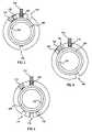
- FIG. 5depicts an alternate embodiment of the invention in a first focus setting
- FIG. 6depicts the alternate embodiment of the invention in a second focus setting.
- FIG. 7depicts the alternate embodiment of the invention in a second focus setting.
- a fixed mount imaging system 100includes an extruded aluminum central housing body 105 .
- a molded-plastic support 115provides support for illumination lenses 250 , and has an opening that reveals the threaded receptacle 240 that receives a threaded lens assembly 120 .
- the extruded aluminum central housing body 105contains an imaging subsystem 300 for acquiring and decoding an image of a symbol or bar code.
- the imaging subsystemincludes a CMOS imager 310 , that is preferably a Micron MT9V022 sensor with a global shutter, for detecting an image projected onto the imager 310 by the threaded barrel lens 120 .
- the imager 310is mounted on an imaging board 315 , with LED illuminators 320 that are optically aligned with the illumination lenses 250 , and the imaging board 315 is attached to the housing body 105 internally through fasteners (not shown).
- a CCD image sensor or image sensing arrayscan be used for the imager 310 .
- a processor board 325 and an I/O board 330are shown as a pair of parallel boards that are interconnected with conventional circuit board connectors, and are electrically connected to the imager board through an interface cable or connector (not shown).
- the imaging subsystem 300is inserted into the rear of the housing 105 , and is captured and protected by the end cover 340 .
- the end cover 340may have a port (not shown) for entry or connection of an interface cable, or it may enclose an internal antenna for reception of wireless communications for communication with a host system, or networked to a client display on a remote system.
- the interface cablemay be Ethernet, USB, Firewire, or another suitable data network, including wireless protocols.
- the imaging subsystem 300may include one or more LED indicators that can be viewed through the end cover 340 , or through viewing ports machined in the housing 105 , that can display status information of the reader, or status information relating to the success of the current or previous read/decode attempt during run time.
- imaging system 100 shownis intended for fixed mounting, the description herein is equally applicable to a hand held unit, with the addition of a suitable handle, and/or a trigger.
- the threaded lends assembly 120is threadedly engaged into the threaded receptacle 240 .
- the threaded lens assembly 120 in the illustrative embodimentis a standard M12 lens, with an outer diameter of 12 mm with a thread pitch of 0.5 mm.
- the lens 120is threaded into the receptacle 240 to a predetermined depth—e.g., the focal position that will provide an adequate level of sharpness to successfully decode an image of a symbol at a first working position.
- the adjustment collar 140 that forms an opening 180is attached to the lens assembly 120 with an adhesive ring 130 , or press-fit to the lends assembly 120 .
- the rotation limiting stop 150 on the adjustment collar 140is positioned adjacent to the housing stop 110 , so that once the collar 140 is attached to the lens 120 , the total rotational adjustment of the focus is limited to not more than approximately one revolution.
- a transparent cover 200is attached to the housing 105 with fasteners (not shown) cooperative with cover holes 220 and housing receptacles 230 .
- Appropriate fastenerscan be screws, or snap-locking fasteners that could facilitate removal and replacement of the cover 200 without the need for tools.
- the cover 200has a key 210 that engages in one of a first slot 160 , a second slot 170 , or a third slot 190 , all in the adjustment collar 140 , depending on the angular orientation of the collar 140 and lens 120 . Accordingly, in the illustrative embodiment, one of three focus settings can be attained, with the cover 200 secured to the housing 105 .
- the keycan be attached to the housing as well as the cover to selectively engage in a desired key slot during configuration.
- FIG. 2depicts the adjustment collar 140 in a first focus setting position, as viewed from the perspective of the lens assembly 120 upon which it is attached.
- the inner cylindrical surface 270fits over the lens assembly 120 in a press-fit or with the adhesive ring 130 mating to the end of the lens and the inner mating surface 260 .
- the collar 140is rotationally aligned so that the first: slot 160 is in the position that will engage with the key 210 , with the rotation limiting stop 150 adjacent to the housing stop 110 (shown in phantom) thereby limiting the rotation of the collar in the counterclockwise motion as shown.
- the userwill rotate the collar 140 fully clockwise so that the rotation limiting stop 150 makes contact with the housing stop 110 , and then attaching the cover 200 while engaging the key 210 into the first slot 160 . Once the cover 200 is secured in place, the focus setting will be maintained at the first focus setting.
- FIG. 3depicts the adjustment collar 140 in a second focus setting position, as viewed from the perspective of the lens assembly 120 upon which it is attached.
- the inner cylindrical surface 270fits over the lens assembly 120 in a press-fit or with the adhesive ring 130 mating to the end of the lens and the inner mating surface 260 .
- the collar 140is rotationally aligned so that the second slot 170 is in the position that will engage with the key 210 , with the rotation limiting stop 150 adjacent to the housing stop 110 (shown in phantom) thereby limiting the rotation of the collar in the clockwise motion as shown.
- the userwill rotate the collar 140 fully counterclockwise so that the rotation limiting stop 150 makes contact with the housing stop 110 , and then attaching the cover 200 while engaging the key 210 into the second slot 160 . Once the cover 200 is secured in place, the focus setting will be maintained at the second focus setting.
- FIG. 4depicts the adjustment collar 140 in a third focus setting position, as viewed from the perspective of the lens assembly 120 upon which it is attached.
- the inner cylindrical surface 270fits over the lens assembly 120 in a press-fit or with the adhesive ring 130 mating to the end of the lens and the inner mating surface 260 .
- the collar 140is rotationally aligned so that the third slot 190 is in the position that will engage with the key 210 .
- the rotation limiting stop 150is not adjacent to the housing stop 110 (shown in phantom), but instead, approximately halfway between contact with the housing stop 110 in the clockwise and counterclockwise positions.
- the userwill rotate the collar 140 into this third focus setting, and then attaching the cover 200 while engaging the key 210 into the first slot 160 . Once the cover 200 is secured in place, the focus setting will be maintained at the third focus setting.
- the lens assembly 120 having a standard M12 thread pitch and a 6 mm focal lengthwill result in a working range of 40 mm in the first focus position, and a working range of 105 mm in the second focus position.
- the third focus positionwill provide a working range of 65 mm.
- a first focal length indicator 410is marked on the face of the adjustment collar 140 at a location that is aligned with the rotation stop 110 when the collar is rotated to align the key 210 with the first slot 160 , to identify the first focus setting.
- a second focal length indicator 420is marked on the face of the adjustment collar 140 at a location aligned with the rotation stop 110 when the collar is rotated to align the key 210 with the second slot 170 to indicate the position of the second focus setting. As depicted in FIG.
- a third focal length indicator 430is marked on the face of the adjustment collar 140 at a location that is aligned with the rotation stop 110 when the collar is rotated to align the key 210 with the third slot 190 on the adjustment collar 140 to indicate the position of the third focus setting.
- the features indicating the focus settingcan be visible through the clear cover 200 when attached to the housing 105 so that the user can determine the focus setting without removing the cover.
- FIG. 6An alternate embodiment is depicted in FIG. 6 that permits an expanded focus range between the first focus setting and the second focus setting.
- the adjustment collar 140is press-fit or adhered to the lens assembly 120 with an auxiliary spacer 370 that freely rotates around the lens assembly.
- the rotation limiting stop on the adjustment collar 140is rotated against the auxiliary stop 360 that is rotated against the rotation stop 110 .
- the first slot 160will align with the key 210 (not shown) when the cover 200 (not shown) is attached.
- the alternate embodimentis further depicted in FIG. 7 , in a second focus position.
- the adjustment collar 140is rotated nearly two revolutions counter-clockwise so that the rotation limiting stop 150 is against the auxiliary stop 360 by rotating the auxiliary spacer 370 rotated nearly a revolution, so that the auxiliary stop 360 is against the rotation stop 110 .
- the second slot 170is aligned with the key 210 (not shown) when the cover 200 (not shown) is attached.
Landscapes
- Physics & Mathematics (AREA)
- Electromagnetism (AREA)
- Engineering & Computer Science (AREA)
- General Physics & Mathematics (AREA)
- Health & Medical Sciences (AREA)
- General Health & Medical Sciences (AREA)
- Toxicology (AREA)
- Artificial Intelligence (AREA)
- Computer Vision & Pattern Recognition (AREA)
- Theoretical Computer Science (AREA)
- Optics & Photonics (AREA)
- Studio Devices (AREA)
Abstract
Description
Claims (17)
Priority Applications (1)
| Application Number | Priority Date | Filing Date | Title |
|---|---|---|---|
| US11/744,310US7549582B1 (en) | 2006-05-30 | 2007-05-04 | Method and apparatus for adjusting focus in a symbology reader |
Applications Claiming Priority (2)
| Application Number | Priority Date | Filing Date | Title |
|---|---|---|---|
| US42083006A | 2006-05-30 | 2006-05-30 | |
| US11/744,310US7549582B1 (en) | 2006-05-30 | 2007-05-04 | Method and apparatus for adjusting focus in a symbology reader |
Related Parent Applications (1)
| Application Number | Title | Priority Date | Filing Date |
|---|---|---|---|
| US42083006AContinuation | 2006-05-30 | 2006-05-30 |
Publications (1)
| Publication Number | Publication Date |
|---|---|
| US7549582B1true US7549582B1 (en) | 2009-06-23 |
Family
ID=40765851
Family Applications (1)
| Application Number | Title | Priority Date | Filing Date |
|---|---|---|---|
| US11/744,310Active2026-06-13US7549582B1 (en) | 2006-05-30 | 2007-05-04 | Method and apparatus for adjusting focus in a symbology reader |
Country Status (1)
| Country | Link |
|---|---|
| US (1) | US7549582B1 (en) |
Cited By (12)
| Publication number | Priority date | Publication date | Assignee | Title |
|---|---|---|---|---|
| US20080158678A1 (en)* | 2006-12-29 | 2008-07-03 | Cognex Corporation | Manually adjustable ruggedized focus mechanism |
| US20100176319A1 (en)* | 2009-01-12 | 2010-07-15 | Cognex Corporation | Modular focus system for image based code readers (as amended) |
| US8181878B2 (en) | 2006-01-25 | 2012-05-22 | Cognex Technology And Investment Corporation | Method and apparatus for providing a focus indication for optical imaging of visual codes |
| US8302864B2 (en) | 2007-12-28 | 2012-11-06 | Cognex Corporation | Method and apparatus using aiming pattern for machine vision training |
| US8646689B2 (en) | 2007-12-28 | 2014-02-11 | Cognex Corporation | Deformable light pattern for machine vision system |
| US9746636B2 (en) | 2012-10-19 | 2017-08-29 | Cognex Corporation | Carrier frame and circuit board for an electronic device |
| US10067312B2 (en) | 2011-11-22 | 2018-09-04 | Cognex Corporation | Vision system camera with mount for multiple lens types |
| JP2019191561A (en)* | 2018-02-09 | 2019-10-31 | ジック アーゲー | Camera and method for focus adjustment |
| US20190361194A1 (en)* | 2011-11-22 | 2019-11-28 | Cognex Corporation | Vision system camera with mount for multiple lens types and lens module for the same |
| US10498933B2 (en) | 2011-11-22 | 2019-12-03 | Cognex Corporation | Camera system with exchangeable illumination assembly |
| CN112817114A (en)* | 2019-10-31 | 2021-05-18 | 矢崎总业株式会社 | mirror device |
| US11606483B2 (en)* | 2012-10-04 | 2023-03-14 | Cognex Corporation | Symbology reader with multi-core processor |
Citations (23)
| Publication number | Priority date | Publication date | Assignee | Title |
|---|---|---|---|---|
| US4072396A (en)* | 1975-07-10 | 1978-02-07 | W. R. Weaver | Focussing objective mechanism for telescopic rifle sights |
| US4160590A (en)* | 1978-04-17 | 1979-07-10 | Polaroid Corporation | Removable (lens position limiting) stop for auto-manual focusing cameras |
| US4478491A (en)* | 1980-06-18 | 1984-10-23 | Canon Kabushiki Kaisha | Focus presetting mechanism for a camera lens assembly |
| US4490018A (en)* | 1982-03-12 | 1984-12-25 | Kino Precision Industries, Ltd. | Photographic lens with variable range focus adjustment |
| US4494828A (en)* | 1981-04-09 | 1985-01-22 | Minolta Camera Kabushiki Kaisha | Zoom lens system of relatively high zoom ratio ranging to wide angle photography |
| US4591253A (en) | 1983-10-06 | 1986-05-27 | Robotic Vision Systems, Inc. | Adaptive vision system |
| US5247152A (en) | 1991-02-25 | 1993-09-21 | Blankenship George D | Plasma torch with improved cooling |
| US5349172A (en) | 1992-02-27 | 1994-09-20 | Alex Roustaei | Optical scanning head |
| US5587843A (en)* | 1995-06-06 | 1996-12-24 | Industrial Technology Research Institute | Zoom lens mechanism |
| US5773810A (en) | 1996-03-29 | 1998-06-30 | Welch Allyn, Inc. | Method for generating real time degree of focus signal for handheld imaging device |
| US5825559A (en)* | 1997-06-27 | 1998-10-20 | Eastman Kodak Company | Optical assembly having a dual purpose focus |
| US6073851A (en) | 1994-12-23 | 2000-06-13 | Spectra-Physics Scanning Systems, Inc. | Multi-focus optical reader with masked or apodized lens |
| US6179208B1 (en) | 1997-01-31 | 2001-01-30 | Metanetics Corporation | Portable data collection device with variable focusing module for optic assembly |
| US6340114B1 (en) | 1998-06-12 | 2002-01-22 | Symbol Technologies, Inc. | Imaging engine and method for code readers |
| US6449430B1 (en)* | 1999-01-11 | 2002-09-10 | Fuji Photo Film Co., Ltd. | Lens-fitted photo film unit and assembling method for the same |
| US20020191309A1 (en)* | 2001-06-15 | 2002-12-19 | Mark Taylor | Lens mounting apparatus |
| US6832729B1 (en)* | 2001-03-23 | 2004-12-21 | Zih Corp. | Portable data collection device for reading fluorescent indicia |
| US6845915B2 (en) | 1997-02-03 | 2005-01-25 | Symbol Technologies, Inc. | Extended range bar code reader |
| US20060034596A1 (en)* | 2004-08-13 | 2006-02-16 | Pentax Corporation | Assembly-stage focus adjustment mechanism of a zoom lens |
| US20060055819A1 (en)* | 2004-09-16 | 2006-03-16 | Alex Pokrovsky | Video surveillance camera |
| US7025271B2 (en) | 2002-12-18 | 2006-04-11 | Symbol Technologies, Inc. | Imaging optical code reader having selectable depths of field |
| US7073715B2 (en) | 2003-02-13 | 2006-07-11 | Symbol Technologies, Inc. | Interface for interfacing an imaging engine to an optical code reader |
| US7222793B2 (en) | 2003-07-09 | 2007-05-29 | Symbol Technologies, Inc. | Arrangement and method of imaging one-dimensional and two-dimensional optical codes at a plurality of focal planes |
- 2007
- 2007-05-04USUS11/744,310patent/US7549582B1/enactiveActive
Patent Citations (24)
| Publication number | Priority date | Publication date | Assignee | Title |
|---|---|---|---|---|
| US4072396A (en)* | 1975-07-10 | 1978-02-07 | W. R. Weaver | Focussing objective mechanism for telescopic rifle sights |
| US4160590A (en)* | 1978-04-17 | 1979-07-10 | Polaroid Corporation | Removable (lens position limiting) stop for auto-manual focusing cameras |
| US4478491A (en)* | 1980-06-18 | 1984-10-23 | Canon Kabushiki Kaisha | Focus presetting mechanism for a camera lens assembly |
| US4494828A (en)* | 1981-04-09 | 1985-01-22 | Minolta Camera Kabushiki Kaisha | Zoom lens system of relatively high zoom ratio ranging to wide angle photography |
| US4490018A (en)* | 1982-03-12 | 1984-12-25 | Kino Precision Industries, Ltd. | Photographic lens with variable range focus adjustment |
| US4591253A (en) | 1983-10-06 | 1986-05-27 | Robotic Vision Systems, Inc. | Adaptive vision system |
| US5247152A (en) | 1991-02-25 | 1993-09-21 | Blankenship George D | Plasma torch with improved cooling |
| US5349172A (en) | 1992-02-27 | 1994-09-20 | Alex Roustaei | Optical scanning head |
| US6073851A (en) | 1994-12-23 | 2000-06-13 | Spectra-Physics Scanning Systems, Inc. | Multi-focus optical reader with masked or apodized lens |
| US5587843A (en)* | 1995-06-06 | 1996-12-24 | Industrial Technology Research Institute | Zoom lens mechanism |
| US5773810A (en) | 1996-03-29 | 1998-06-30 | Welch Allyn, Inc. | Method for generating real time degree of focus signal for handheld imaging device |
| US6179208B1 (en) | 1997-01-31 | 2001-01-30 | Metanetics Corporation | Portable data collection device with variable focusing module for optic assembly |
| US6431452B2 (en) | 1997-01-31 | 2002-08-13 | Metanetics Corporation | Portable data collection device with variable focusing module for optic assembly |
| US6845915B2 (en) | 1997-02-03 | 2005-01-25 | Symbol Technologies, Inc. | Extended range bar code reader |
| US5825559A (en)* | 1997-06-27 | 1998-10-20 | Eastman Kodak Company | Optical assembly having a dual purpose focus |
| US6340114B1 (en) | 1998-06-12 | 2002-01-22 | Symbol Technologies, Inc. | Imaging engine and method for code readers |
| US6449430B1 (en)* | 1999-01-11 | 2002-09-10 | Fuji Photo Film Co., Ltd. | Lens-fitted photo film unit and assembling method for the same |
| US6832729B1 (en)* | 2001-03-23 | 2004-12-21 | Zih Corp. | Portable data collection device for reading fluorescent indicia |
| US20020191309A1 (en)* | 2001-06-15 | 2002-12-19 | Mark Taylor | Lens mounting apparatus |
| US7025271B2 (en) | 2002-12-18 | 2006-04-11 | Symbol Technologies, Inc. | Imaging optical code reader having selectable depths of field |
| US7073715B2 (en) | 2003-02-13 | 2006-07-11 | Symbol Technologies, Inc. | Interface for interfacing an imaging engine to an optical code reader |
| US7222793B2 (en) | 2003-07-09 | 2007-05-29 | Symbol Technologies, Inc. | Arrangement and method of imaging one-dimensional and two-dimensional optical codes at a plurality of focal planes |
| US20060034596A1 (en)* | 2004-08-13 | 2006-02-16 | Pentax Corporation | Assembly-stage focus adjustment mechanism of a zoom lens |
| US20060055819A1 (en)* | 2004-09-16 | 2006-03-16 | Alex Pokrovsky | Video surveillance camera |
Cited By (24)
| Publication number | Priority date | Publication date | Assignee | Title |
|---|---|---|---|---|
| US8181878B2 (en) | 2006-01-25 | 2012-05-22 | Cognex Technology And Investment Corporation | Method and apparatus for providing a focus indication for optical imaging of visual codes |
| US20080158678A1 (en)* | 2006-12-29 | 2008-07-03 | Cognex Corporation | Manually adjustable ruggedized focus mechanism |
| US8033670B2 (en) | 2006-12-29 | 2011-10-11 | Cognex Corporation | Manually adjustable ruggedized focus mechanism |
| US9039208B2 (en) | 2006-12-29 | 2015-05-26 | Cognex Corporation | Manually adjustable ruggedized focus mechanism |
| US8302864B2 (en) | 2007-12-28 | 2012-11-06 | Cognex Corporation | Method and apparatus using aiming pattern for machine vision training |
| US8646689B2 (en) | 2007-12-28 | 2014-02-11 | Cognex Corporation | Deformable light pattern for machine vision system |
| US20100176319A1 (en)* | 2009-01-12 | 2010-07-15 | Cognex Corporation | Modular focus system for image based code readers (as amended) |
| US8134116B2 (en) | 2009-01-12 | 2012-03-13 | Cognex Corporation | Modular focus system for image based code readers |
| US8803060B2 (en) | 2009-01-12 | 2014-08-12 | Cognex Corporation | Modular focus system alignment for image based readers |
| US20190361194A1 (en)* | 2011-11-22 | 2019-11-28 | Cognex Corporation | Vision system camera with mount for multiple lens types and lens module for the same |
| US11366284B2 (en)* | 2011-11-22 | 2022-06-21 | Cognex Corporation | Vision system camera with mount for multiple lens types and lens module for the same |
| US11936964B2 (en) | 2011-11-22 | 2024-03-19 | Cognex Corporation | Camera system with exchangeable illumination assembly |
| US11921350B2 (en) | 2011-11-22 | 2024-03-05 | Cognex Corporation | Vision system camera with mount for multiple lens types and lens module for the same |
| US10498933B2 (en) | 2011-11-22 | 2019-12-03 | Cognex Corporation | Camera system with exchangeable illumination assembly |
| US10498934B2 (en) | 2011-11-22 | 2019-12-03 | Cognex Corporation | Camera system with exchangeable illumination assembly |
| US10678019B2 (en) | 2011-11-22 | 2020-06-09 | Cognex Corporation | Vision system camera with mount for multiple lens types |
| US10067312B2 (en) | 2011-11-22 | 2018-09-04 | Cognex Corporation | Vision system camera with mount for multiple lens types |
| US11115566B2 (en) | 2011-11-22 | 2021-09-07 | Cognex Corporation | Camera system with exchangeable illumination assembly |
| US11606483B2 (en)* | 2012-10-04 | 2023-03-14 | Cognex Corporation | Symbology reader with multi-core processor |
| US10754122B2 (en) | 2012-10-19 | 2020-08-25 | Cognex Corporation | Carrier frame and circuit board for an electronic device |
| US9746636B2 (en) | 2012-10-19 | 2017-08-29 | Cognex Corporation | Carrier frame and circuit board for an electronic device |
| JP2019191561A (en)* | 2018-02-09 | 2019-10-31 | ジック アーゲー | Camera and method for focus adjustment |
| CN112817114A (en)* | 2019-10-31 | 2021-05-18 | 矢崎总业株式会社 | mirror device |
| CN112817114B (en)* | 2019-10-31 | 2022-09-30 | 矢崎总业株式会社 | Mirror device |
Similar Documents
| Publication | Publication Date | Title |
|---|---|---|
| US7549582B1 (en) | Method and apparatus for adjusting focus in a symbology reader | |
| US7823789B2 (en) | Low profile illumination for direct part mark readers | |
| JP5719311B2 (en) | Modular focus system for image reader | |
| JP2899113B2 (en) | Method and apparatus for portable non-contact label imager | |
| US9773142B2 (en) | System and method for selectively reading code symbols | |
| US6034379A (en) | Code reader having replaceable optics assemblies supporting multiple illuminators | |
| US9307128B2 (en) | Lens mount | |
| US11574137B2 (en) | Handheld ID-reading system with integrated illumination assembly | |
| US20090212111A1 (en) | System and method for identifying erasures in a 2d symbol | |
| US8469276B1 (en) | Handheld code reader having a motion sensor | |
| CA2157134A1 (en) | Portable optical reader system and method | |
| US11449696B2 (en) | Alternative illuminator assembly and mobile imaging apparatus for improved direct part marking reading | |
| EP1599823A1 (en) | Optical code reader with autofocus and interface unit | |
| CN107944315B (en) | Mobile imaging bar code scanner | |
| KR102722836B1 (en) | Optical arrangements for small size wide angle auto focus imaging lens for high resolution sensors | |
| US20200257867A1 (en) | Code reader with extended reading range | |
| WO2006088271A1 (en) | Apparatus for stamp type barcode reader | |
| KR200388546Y1 (en) | Apparatus for stamp type barcode reader | |
| CN114004243A (en) | Portable yard rifle of sweeping | |
| KR20060091703A (en) | Stamped Barcode Reader | |
| Mandos | Philips bar dots and alphas: identification under toughconditions |
Legal Events
| Date | Code | Title | Description |
|---|---|---|---|
| AS | Assignment | Owner name:COGNEX CORPORATION, MASSACHUSETTS Free format text:ASSIGNMENT OF ASSIGNORS INTEREST;ASSIGNOR:NUNNINK, LAURENS;REEL/FRAME:019250/0550 Effective date:20060731 | |
| STCF | Information on status: patent grant | Free format text:PATENTED CASE | |
| FPAY | Fee payment | Year of fee payment:4 | |
| AS | Assignment | Owner name:COGNEX TECHNOLOGY AND INVESTMENT CORPORATION, CALI Free format text:CORRECTIVE ASSIGNMENT TO CORRECT THE ASSIGNEE'S NAME PREVIOUSLY RECORDED AT REEL: 019250 FRAME: 0550. ASSIGNOR(S) HEREBY CONFIRMS THE ASSIGNMENT;ASSIGNOR:NUNNINK, LAURENS;REEL/FRAME:033934/0784 Effective date:20060731 | |
| AS | Assignment | Owner name:COGNEX TECHNOLOGY AND INVESTMENT LLC, MASSACHUSETT Free format text:CORRECTIVE ASSIGNMENT TO CORRECT THE NAME AND COMPANY IDENTITY OF ASSIGNEE PREVIOUSLY RECORDED ON REEL 033934 FRAME 0784. ASSIGNOR(S) HEREBY CONFIRMS THE ASSIGNMENT;ASSIGNOR:NUNNINK, LAURENS;REEL/FRAME:033988/0793 Effective date:20140519 | |
| FPAY | Fee payment | Year of fee payment:8 | |
| MAFP | Maintenance fee payment | Free format text:PAYMENT OF MAINTENANCE FEE, 12TH YEAR, LARGE ENTITY (ORIGINAL EVENT CODE: M1553); ENTITY STATUS OF PATENT OWNER: LARGE ENTITY Year of fee payment:12 | |
| AS | Assignment | Owner name:COGNEX CORPORATION, MASSACHUSETTS Free format text:ASSIGNMENT OF ASSIGNORS INTEREST;ASSIGNOR:COGNEX TECHNOLOGY AND INVESTMENT LLC;REEL/FRAME:068221/0679 Effective date:20240101 |