US7548826B2 - Power monitoring and testing - Google Patents
Power monitoring and testingDownload PDFInfo
- Publication number
- US7548826B2 US7548826B2US11/556,496US55649606AUS7548826B2US 7548826 B2US7548826 B2US 7548826B2US 55649606 AUS55649606 AUS 55649606AUS 7548826 B2US7548826 B2US 7548826B2
- Authority
- US
- United States
- Prior art keywords
- data
- test
- interface
- server
- site
- Prior art date
- Legal status (The legal status is an assumption and is not a legal conclusion. Google has not performed a legal analysis and makes no representation as to the accuracy of the status listed.)
- Active, expires
Links
Images


Classifications
- H—ELECTRICITY
- H04—ELECTRIC COMMUNICATION TECHNIQUE
- H04Q—SELECTING
- H04Q9/00—Arrangements in telecontrol or telemetry systems for selectively calling a substation from a main station, in which substation desired apparatus is selected for applying a control signal thereto or for obtaining measured values therefrom
- G—PHYSICS
- G06—COMPUTING OR CALCULATING; COUNTING
- G06Q—INFORMATION AND COMMUNICATION TECHNOLOGY [ICT] SPECIALLY ADAPTED FOR ADMINISTRATIVE, COMMERCIAL, FINANCIAL, MANAGERIAL OR SUPERVISORY PURPOSES; SYSTEMS OR METHODS SPECIALLY ADAPTED FOR ADMINISTRATIVE, COMMERCIAL, FINANCIAL, MANAGERIAL OR SUPERVISORY PURPOSES, NOT OTHERWISE PROVIDED FOR
- G06Q20/00—Payment architectures, schemes or protocols
- G06Q20/08—Payment architectures
- G06Q20/10—Payment architectures specially adapted for electronic funds transfer [EFT] systems; specially adapted for home banking systems
- G06Q20/102—Bill distribution or payments
- G—PHYSICS
- G06—COMPUTING OR CALCULATING; COUNTING
- G06Q—INFORMATION AND COMMUNICATION TECHNOLOGY [ICT] SPECIALLY ADAPTED FOR ADMINISTRATIVE, COMMERCIAL, FINANCIAL, MANAGERIAL OR SUPERVISORY PURPOSES; SYSTEMS OR METHODS SPECIALLY ADAPTED FOR ADMINISTRATIVE, COMMERCIAL, FINANCIAL, MANAGERIAL OR SUPERVISORY PURPOSES, NOT OTHERWISE PROVIDED FOR
- G06Q30/00—Commerce
- G06Q30/02—Marketing; Price estimation or determination; Fundraising
- G06Q30/0207—Discounts or incentives, e.g. coupons or rebates
- G—PHYSICS
- G06—COMPUTING OR CALCULATING; COUNTING
- G06Q—INFORMATION AND COMMUNICATION TECHNOLOGY [ICT] SPECIALLY ADAPTED FOR ADMINISTRATIVE, COMMERCIAL, FINANCIAL, MANAGERIAL OR SUPERVISORY PURPOSES; SYSTEMS OR METHODS SPECIALLY ADAPTED FOR ADMINISTRATIVE, COMMERCIAL, FINANCIAL, MANAGERIAL OR SUPERVISORY PURPOSES, NOT OTHERWISE PROVIDED FOR
- G06Q30/00—Commerce
- G06Q30/02—Marketing; Price estimation or determination; Fundraising
- G06Q30/0241—Advertisements
- G06Q30/0273—Determination of fees for advertising
- H—ELECTRICITY
- H02—GENERATION; CONVERSION OR DISTRIBUTION OF ELECTRIC POWER
- H02J—CIRCUIT ARRANGEMENTS OR SYSTEMS FOR SUPPLYING OR DISTRIBUTING ELECTRIC POWER; SYSTEMS FOR STORING ELECTRIC ENERGY
- H02J13/00—Circuit arrangements for providing remote indication of network conditions, e.g. an instantaneous record of the open or closed condition of each circuitbreaker in the network; Circuit arrangements for providing remote control of switching means in a power distribution network, e.g. switching in and out of current consumers by using a pulse code signal carried by the network
- H02J13/00001—Circuit arrangements for providing remote indication of network conditions, e.g. an instantaneous record of the open or closed condition of each circuitbreaker in the network; Circuit arrangements for providing remote control of switching means in a power distribution network, e.g. switching in and out of current consumers by using a pulse code signal carried by the network characterised by the display of information or by user interaction, e.g. supervisory control and data acquisition systems [SCADA] or graphical user interfaces [GUI]
- H—ELECTRICITY
- H02—GENERATION; CONVERSION OR DISTRIBUTION OF ELECTRIC POWER
- H02J—CIRCUIT ARRANGEMENTS OR SYSTEMS FOR SUPPLYING OR DISTRIBUTING ELECTRIC POWER; SYSTEMS FOR STORING ELECTRIC ENERGY
- H02J13/00—Circuit arrangements for providing remote indication of network conditions, e.g. an instantaneous record of the open or closed condition of each circuitbreaker in the network; Circuit arrangements for providing remote control of switching means in a power distribution network, e.g. switching in and out of current consumers by using a pulse code signal carried by the network
- H02J13/00002—Circuit arrangements for providing remote indication of network conditions, e.g. an instantaneous record of the open or closed condition of each circuitbreaker in the network; Circuit arrangements for providing remote control of switching means in a power distribution network, e.g. switching in and out of current consumers by using a pulse code signal carried by the network characterised by monitoring
- H—ELECTRICITY
- H02—GENERATION; CONVERSION OR DISTRIBUTION OF ELECTRIC POWER
- H02J—CIRCUIT ARRANGEMENTS OR SYSTEMS FOR SUPPLYING OR DISTRIBUTING ELECTRIC POWER; SYSTEMS FOR STORING ELECTRIC ENERGY
- H02J13/00—Circuit arrangements for providing remote indication of network conditions, e.g. an instantaneous record of the open or closed condition of each circuitbreaker in the network; Circuit arrangements for providing remote control of switching means in a power distribution network, e.g. switching in and out of current consumers by using a pulse code signal carried by the network
- H02J13/00032—Systems characterised by the controlled or operated power network elements or equipment, the power network elements or equipment not otherwise provided for
- H02J13/00036—Systems characterised by the controlled or operated power network elements or equipment, the power network elements or equipment not otherwise provided for the elements or equipment being or involving switches, relays or circuit breakers
- H—ELECTRICITY
- H02—GENERATION; CONVERSION OR DISTRIBUTION OF ELECTRIC POWER
- H02J—CIRCUIT ARRANGEMENTS OR SYSTEMS FOR SUPPLYING OR DISTRIBUTING ELECTRIC POWER; SYSTEMS FOR STORING ELECTRIC ENERGY
- H02J13/00—Circuit arrangements for providing remote indication of network conditions, e.g. an instantaneous record of the open or closed condition of each circuitbreaker in the network; Circuit arrangements for providing remote control of switching means in a power distribution network, e.g. switching in and out of current consumers by using a pulse code signal carried by the network
- H02J13/00006—Circuit arrangements for providing remote indication of network conditions, e.g. an instantaneous record of the open or closed condition of each circuitbreaker in the network; Circuit arrangements for providing remote control of switching means in a power distribution network, e.g. switching in and out of current consumers by using a pulse code signal carried by the network characterised by information or instructions transport means between the monitoring, controlling or managing units and monitored, controlled or operated power network element or electrical equipment
- H02J13/00028—Circuit arrangements for providing remote indication of network conditions, e.g. an instantaneous record of the open or closed condition of each circuitbreaker in the network; Circuit arrangements for providing remote control of switching means in a power distribution network, e.g. switching in and out of current consumers by using a pulse code signal carried by the network characterised by information or instructions transport means between the monitoring, controlling or managing units and monitored, controlled or operated power network element or electrical equipment involving the use of Internet protocols
- Y—GENERAL TAGGING OF NEW TECHNOLOGICAL DEVELOPMENTS; GENERAL TAGGING OF CROSS-SECTIONAL TECHNOLOGIES SPANNING OVER SEVERAL SECTIONS OF THE IPC; TECHNICAL SUBJECTS COVERED BY FORMER USPC CROSS-REFERENCE ART COLLECTIONS [XRACs] AND DIGESTS
- Y02—TECHNOLOGIES OR APPLICATIONS FOR MITIGATION OR ADAPTATION AGAINST CLIMATE CHANGE
- Y02E—REDUCTION OF GREENHOUSE GAS [GHG] EMISSIONS, RELATED TO ENERGY GENERATION, TRANSMISSION OR DISTRIBUTION
- Y02E60/00—Enabling technologies; Technologies with a potential or indirect contribution to GHG emissions mitigation
- Y—GENERAL TAGGING OF NEW TECHNOLOGICAL DEVELOPMENTS; GENERAL TAGGING OF CROSS-SECTIONAL TECHNOLOGIES SPANNING OVER SEVERAL SECTIONS OF THE IPC; TECHNICAL SUBJECTS COVERED BY FORMER USPC CROSS-REFERENCE ART COLLECTIONS [XRACs] AND DIGESTS
- Y04—INFORMATION OR COMMUNICATION TECHNOLOGIES HAVING AN IMPACT ON OTHER TECHNOLOGY AREAS
- Y04S—SYSTEMS INTEGRATING TECHNOLOGIES RELATED TO POWER NETWORK OPERATION, COMMUNICATION OR INFORMATION TECHNOLOGIES FOR IMPROVING THE ELECTRICAL POWER GENERATION, TRANSMISSION, DISTRIBUTION, MANAGEMENT OR USAGE, i.e. SMART GRIDS
- Y04S10/00—Systems supporting electrical power generation, transmission or distribution
- Y04S10/30—State monitoring, e.g. fault, temperature monitoring, insulator monitoring, corona discharge
- Y—GENERAL TAGGING OF NEW TECHNOLOGICAL DEVELOPMENTS; GENERAL TAGGING OF CROSS-SECTIONAL TECHNOLOGIES SPANNING OVER SEVERAL SECTIONS OF THE IPC; TECHNICAL SUBJECTS COVERED BY FORMER USPC CROSS-REFERENCE ART COLLECTIONS [XRACs] AND DIGESTS
- Y04—INFORMATION OR COMMUNICATION TECHNOLOGIES HAVING AN IMPACT ON OTHER TECHNOLOGY AREAS
- Y04S—SYSTEMS INTEGRATING TECHNOLOGIES RELATED TO POWER NETWORK OPERATION, COMMUNICATION OR INFORMATION TECHNOLOGIES FOR IMPROVING THE ELECTRICAL POWER GENERATION, TRANSMISSION, DISTRIBUTION, MANAGEMENT OR USAGE, i.e. SMART GRIDS
- Y04S10/00—Systems supporting electrical power generation, transmission or distribution
- Y04S10/40—Display of information, e.g. of data or controls
- Y—GENERAL TAGGING OF NEW TECHNOLOGICAL DEVELOPMENTS; GENERAL TAGGING OF CROSS-SECTIONAL TECHNOLOGIES SPANNING OVER SEVERAL SECTIONS OF THE IPC; TECHNICAL SUBJECTS COVERED BY FORMER USPC CROSS-REFERENCE ART COLLECTIONS [XRACs] AND DIGESTS
- Y04—INFORMATION OR COMMUNICATION TECHNOLOGIES HAVING AN IMPACT ON OTHER TECHNOLOGY AREAS
- Y04S—SYSTEMS INTEGRATING TECHNOLOGIES RELATED TO POWER NETWORK OPERATION, COMMUNICATION OR INFORMATION TECHNOLOGIES FOR IMPROVING THE ELECTRICAL POWER GENERATION, TRANSMISSION, DISTRIBUTION, MANAGEMENT OR USAGE, i.e. SMART GRIDS
- Y04S50/00—Market activities related to the operation of systems integrating technologies related to power network operation or related to communication or information technologies
- Y04S50/12—Billing, invoicing, buying or selling transactions or other related activities, e.g. cost or usage evaluation
- Y—GENERAL TAGGING OF NEW TECHNOLOGICAL DEVELOPMENTS; GENERAL TAGGING OF CROSS-SECTIONAL TECHNOLOGIES SPANNING OVER SEVERAL SECTIONS OF THE IPC; TECHNICAL SUBJECTS COVERED BY FORMER USPC CROSS-REFERENCE ART COLLECTIONS [XRACs] AND DIGESTS
- Y04—INFORMATION OR COMMUNICATION TECHNOLOGIES HAVING AN IMPACT ON OTHER TECHNOLOGY AREAS
- Y04S—SYSTEMS INTEGRATING TECHNOLOGIES RELATED TO POWER NETWORK OPERATION, COMMUNICATION OR INFORMATION TECHNOLOGIES FOR IMPROVING THE ELECTRICAL POWER GENERATION, TRANSMISSION, DISTRIBUTION, MANAGEMENT OR USAGE, i.e. SMART GRIDS
- Y04S50/00—Market activities related to the operation of systems integrating technologies related to power network operation or related to communication or information technologies
- Y04S50/14—Marketing, i.e. market research and analysis, surveying, promotions, advertising, buyer profiling, customer management or rewards
Definitions
- the present disclosurerelates to monitoring, management, and testing of power systems.
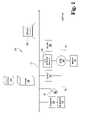
- FIG. 1is a block diagram showing portions of a site's power generation, monitoring, management, and testing system according to one embodiment.
- FIG. 2is a block diagram of a server according to the first embodiment.
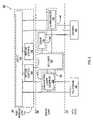
- FIG. 3is a block diagram showing portions of an enterprise's power generation, monitoring, management, and testing system according to a second embodiment.
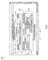
- FIG. 4is a block diagram of software entities, modules, and the like, including call flows and security identities in a third embodiment.
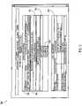
- FIG. 5is a block diagram of enterprise-wide server software system entities, modules, and the like, including call flows and security identities, according to a fourth embodiment.
- FIG. 6is an example screen in the “live view” interface of a fifth embodiment.
- FIG. 7is an example screen showing device status information according to the fifth embodiment.
- FIG. 8is an example screen in the test scripting interface of the fifth embodiment.
- FIG. 9is an example screen in the test schedule/status interface of the fifth embodiment.
- FIG. 10is an example screen in the month-level test schedule/status interface of the fifth embodiment.
- FIG. 11is an example report from a test in the fifth embodiment.
- FIG. 12is an example screen in the reporting interface of the fifth embodiment.
- FIG. 13is an example screen of the alarm management interface of the fifth embodiment.
- FIG. 14is an example screen in the alarm history interface of the fifth embodiment.
- FIG. 15is an example screen in the logging group configuration interface of the fifth embodiment.
- one form of the present inventionis a system for monitoring, managing, and testing a power system having local generators and connections to the utility power grid.
- a system 100is shown with a server 105 and storage 110 connected to data network 115 .
- Server 105in this embodiment includes processor 120 , memory 125 , network interface 130 , input interface 135 , and output interface 140 , as shown in FIG. 2 and as will be understood by those skilled in the art. Power, ground, clock, and other signals and circuitry are omitted for clarity, but will be understood and easily implemented by those skilled in the art.
- network interface 130 in this embodimentconnects server 105 to network 115 for communication of data between server 105 and other devices attached to network 115 .
- Input interface 135manages communication between processor 120 and one or more push-buttons, UARTs, IR and/or RF receivers or transceivers, decoders, or other devices, as well as traditional keyboard and mouse devices.
- Output interface 140provides a video signal to display 145 , and may provide signals to one or more additional output devices such as LEDs, LCDs, or audio output devices, or a combination of these and other output devices and techniques as will occur to those skilled in the art.
- Processor 120in some embodiments is a microcontroller or general purpose microprocessor that reads its program from memory 125 .
- Processor 120may be comprised of one or more components configured as a single unit. Alternatively, when of a multi-component form, processor 120 may have one or more components located remotely relative to the others.
- One or more components of processor 120may be of the electronic variety including digital circuitry, analog circuitry, or both.
- processor 120is of a conventional, integrated circuit microprocessor arrangement, such as one or more PENTIUM 4 or XEON processors from INTEL Corporation of 2200 Mission College Boulevard, Santa Clara, Calif. 95052, USA, or ATHLON XP or OPTERON processors from Advanced Micro Devices, One AMD Place, Sunnyvale, Calif. 94088, USA.
- ASICsapplication-specific integrated circuits
- general-purpose microprocessorsprogrammable logic arrays, or other devices may be used alone or in combination as will occur to those skilled in the art.
- memory 125in various embodiments includes one or more types such as solid-state electronic memory, magnetic memory, or optical memory, just to name a few.
- memory 125can include solid-state electronic Random Access Memory (RAM), Sequentially Accessible Memory (SAM) (such as the First-In, First-Out (FIFO) variety or the Last-In First-Out (LIFO) variety), Programmable Read-Only Memory (PROM), Electrically Programmable Read-Only Memory (EPROM), or Electrically Erasable Programmable Read-Only Memory (EEPROM); an optical disc memory (such as a recordable, rewritable, or read-only DVD or CD-ROM); a magnetically encoded hard drive, floppy disk, tape, or cartridge media; or a combination of these memory types.
- RAMsolid-state electronic Random Access Memory
- SAMSequentially Accessible Memory
- PROMFirst-In, First-Out
- LIFOLast-In First-Out
- PROMProgrammable Read-Only Memory
- EPROMElectrically Programmable Read-On
- ATS 160provides power to load 155 via Automatic Transfer Switch (ATS) 160 .
- ATS 160manages a partial or total switchover to power generated by generator 165 and delivered through line 170 .
- ATS 160is an automatic transfer switch manufactured by APC (such as its Rack ATS product), Cummins (such as its POWER COMMAND transfer switches), BayTech (such as its ATS Series Transfer Switch), or Caterpillar, just to name a few options.
- generator 165is selected, in various embodiments, from the Caterpillar C175 family, Cummins generator sets, and other models which will occur to those skilled in the art. In some instances, generator 165 and ATS 160 are integrated in a single unit, while in others the units are distinct.
- generator 165includes a built-in interface 175 , which may be used in its factory configuration or supplemented with additional interface hardware and/or software to provide the interface used by system 100 .
- generator 165includes only a limited number of built-in sensors (or none at all), and interface 175 must provide all or substantially all of the instrumentation for that generator 165 .
- generator 165is connected to genset interface module 175 , which collects operational parameters from generator 165 and makes them available to other devices via network 115 .
- the parameters provided by genset interface module 175includes the genset's fuel level, oil pressure, “running” status, water temperature, exhaust temperature, output frequency, engine speed, applied torque, DC output voltage, and running time meter, just to name a few.
- ATS interface module 180detects the state of ATS 160 and makes that information available via network 115 to other devices connected to the network.
- the data made available by ATS interface module 180includes, in various embodiments, its running status, input level, override status, voltage, current, power output, power factor, and the like. In some embodiments, some or all of these variables are captured and made available via network 115 by one or more power meters (not shown) connected to or near the ATS.
- Sensors 185 and 190detect the state of supply lines 170 and 150 , respectively, on the generator and utility inputs, respectively, to ATS 160 . This data is also provided via network 115 to other devices that are connected to network 115 . Camera 195 captures images of generator 165 over time so that devices connected to network 115 and capture and/or display still pictures or motion video of the physical site of generator 165 at desired times. In various embodiments, multiple cameras provide images in a variety of views and/or spectra as necessary or desired. Terminal 199 is also in communication with network 115 and is configured to monitor and/or control other devices on network 115 .
- multiple transfer switches 160 , generators 165 , sensors 185 , 190 , cameras 195 , and interface modules 175 , 180are in communication with network 115 to implement and instrument a system that meets the power needs of a building, organization, institution, or group.
- Multiple terminals 199communicate with server 105 to access data compiled or calculated there, or communicate with other devices and interfaces to read operational parameters or control those devices.
- Server 105collects data produced by interface modules 175 and 180 , sensors 185 and 190 , and camera 195 , storing some or all of that data in storage unit 110 .
- the datamay be stored using any technique that would occur to one skilled in the art, including but not limited to, storing all such data, sampling the data at various intervals for longer-term storage, implementing circular buffers and snapshots, and other strategies.
- Server 105also calculates aggregate information, such as uptime and running time for a device, maxima and minima of operational parameters over time, and the like, and constructs graphical depictions of captured data either on a scheduled, “snapshot” basis or on demand.
- Terminal 199accesses the data on server 105 and (through server 105 ) in storage 110 so that an individual at terminal 199 can monitor and/or control ATS 160 , generator 165 , and/or other controllable devices using that information.
- server 105makes this data available in various forms, such as via FTP, HTTP, automatically generated email, or the like.
- the data provided to terminal 199is substantially real-time information, while in others served data is drawn from a snapshot of the relevant device(s), while in still others some data of each type is available.
- FIG. 3shows a system 200 that includes multiple subsystems 201 a , 201 b , 201 c , and 201 d .
- Each subsystemroughly resembles system 100 as shown in FIG. 1 and discussed in relation thereto, though the various subsystems may be in a single geographical location or multiple locations, could include the same or different numbers of generators 165 , ATS units 160 , sensors 185 , 190 , cameras 195 , and other components, and may include elements that are the same or different in make, model, and/or configuration from those in other subsystems.
- Server 203collects operational parameter information from a server 105 from each subsystem 201 a , 201 b , 201 c , and 201 d , compiles that information, and saves it in storage 205 . Enterprise server 203 also calculates aggregate data and generates graphical displays for showing on monitor 207 and/or terminal 209 .
- network 208(and network 115 in FIG. 1 ) comprises one or more local area networks (LANs), wide area networks (WANs), virtual private networks (VPNs), dedicated communication circuits, device-level (e.g., Modbus) networks, and the like.
- LANslocal area networks
- WANswide area networks
- VPNsvirtual private networks
- One or more routers, switches, subnetworks, bridges, and the Internetmay appear in networks 115 or 208 , or between two or more portions of systems 100 and 200 , as will occur to those skilled in the art.
- a memory 125(see FIG. 2 ) is encoded with programming instructions executable by a processor 120 (again, see FIG. 2 ) to implement software system 202 , which includes user interface layer 210 , service layer 220 , and data layer 250 .
- User interface layer 210manages user interactions with other parts of the software system 202 , including communication of information captured by the system to one or more users.
- Service layer 220manages the business logic and data flow in the system, while data layer 250 manages storage of captured data and configuration information for various system elements and in various repositories.
- user interface layer 210includes ASP.NET client component 212 , which provides a variety of user-interface resources as will be understood in the art.
- OPC web control component 214provides human-machine interface (HMI) components to ASP.NET client 212 for AJAX-style presentation of data and capture of user control events.
- Webcam interface 216accepts a stream of images from a camera 195 (see FIG. 1 ) and provides data to ASP.NET client 212 for display as needed.
- Each of the components in user interface layer 210is associated with a common security identity 218 in its interaction with components in service layer 220 and data layer 250 .
- Service layer 220comprises several elements that manage data flow and implement business logic in the system.
- Control manager 222detects and executes logging events, starts and stops locally connected controllable entities, starts and manages the system configuration state, management of software licensing, and detection of alarm events for notifications (by e-mail, for example).
- Control manager 222communicates with ASP.NET client 212 , which interacts with the state manager 224 , tag manager 226 , and sequencer 228 to implement a state machine that controls operation of the server, maintains session states, and provides new states based on input and programmed transitions.
- Tag manager 226maintains a repository of information about the tags that are available to manage devices through the underlying OPC client 232 , and loads the relevant tag configuration information at system startup, including configuration and device data, data logging configuration, and alarm logging configuration. Meanwhile sequencer 228 manages automated testing of devices according to schedules and commands executed by the system. These four components 222 , 224 , 226 , and 228 share security identity 230 in their interaction with ASP.NET client 212 , OPC client 232 and file storage 252 .
- OPC client 232accesses data via Modbus TCP OPC server 234 , which in this embodiment captures data from network 115 via I/O block 254 .
- OPC server 234is published by Kepware (www.kepware.com), though any industry standards-compliant or other suitable OPC server may be used.
- OPC (“OLE for Process Control,” a Distributed Common Object Model (DCOM) technology) client 232 and OPC server 234share security identity 236 in their interaction with OPC web controls component 214 , tag manager component 226 , logger 238 , and I/O subsystem 254 .
- OPCOPC
- Logger component 238maintains data captured via OPC client 232 in database 256 using techniques that will occur to those skilled in the art. In some embodiments, logger component 238 also stores software events, queries issued, data pulley and capture events, and the like. Logger 238 has its own security identity 240 to authenticate and in some embodiments encrypt some or all of these interactions with OPC client 232 and database 256 .
- alarm manager 242monitors the stream(s) of data that flow through OPC client 232 , checking them against limits defined by the system and/or users as discussed elsewhere herein. When such limits are exceeded, predetermined acts are taken, such as recording the event in database 256 , raising alerts in the user interface via ASP.NET client 212 , sending email or pages, or raising visible and/or audible alarms, to name just a new possibilities.
- Alarm manager 242also has its own security identity 244 to authenticate and secure its interactions, as appropriate, with OPC client 232 , ASP.NET client 212 , and database 256 .
- Data layer 250 in this embodimentcomprises file storage element(s) 252 , I/O controllers and devices 254 , and database 256 .
- File storage 252comprises one or more elements as described above in relation to storage element 110 of FIG. 1 , and provides read/write storage for various elements of the system, including ASP.NET client 212 , tag manager 226 and sequencer 228 .
- file storage 252can be monolithic or distributed, homogeneous or heterogeneous, or have parts of each type as needed or desired for a particular system.
- I/O interface 254provides the interface between server 105 and network 115 , so that data streams can be captured and devices on network 115 can be controlled, and data can be shared with web-based terminals and enterprise-level servers.
- I/O interface 254comprises one or more network interface cards (NICs); Modbus interface hardware; other standard, custom, or proprietary data interfaces, or some combination thereof.
- NICsnetwork interface cards
- Modbus interface hardwareother standard, custom, or proprietary data interfaces, or some combination thereof.
- Database block 256conceptually represents one or more databases, which could take on any of many forms that will occur to those skilled in the art.
- database 256may comprise one or more logical databases, may be monolithic or distributed, may be housed in volatile memory, nonvolatile hard drives, or optical media, and may be of the relational, object-relational, flat, hierarchical, network, object-oriented, semistructured, associative, entity-attribute-value, or context models, to name several examples.
- database 256in some embodiments is hosted on server 105 and stored in storage 110 (see FIG. 1 ), though in other embodiments the host and/or storage is located elsewhere, or in a combination of local and remote locations.
- the “security identities” described hereinprovide distinct entities for control and monitoring of data access.
- these identitiesin some embodiments are used to limit data available to software entities bearing particular identities, authenticate transfers of data between software entities, and/or provide public-key encryption keys for encrypted transfer of data between entities.
- Other applications of security identities in the context of this descriptionwill occur to those skilled in the art.
- system 300comprises user interface layer 310 , service layer 320 , and data layer 350 .
- user interface layer 310includes ASP.NET client 312 for presentation of information to users and capture of user input, and OPC web controls 314 for providing an interface between the data provided through OPC client 332 and the presentation layer of ASP.NET client 312 .
- Webcam interface 316collects and processes data from one or more cameras 195 (see FIG. 1 ) for presentation through ASP.NET client 312 .
- the three components of user interface layer 310share security identity 318 in their interaction with other components of software system 300 .
- Service layer 320comprises configuration loader/sequencer 328 , OPC client 332 , logger 338 , and alarm manager 342 .
- Logger 338 and alarm manager 342operate similarly to the corresponding elements 238 and 242 , respectively, of FIG. 4 , though they have access to and process data from multiple sites 100 and systems 201 . Because they have access to more complete sets of data, they can provide a more complete picture of the activities in system 200 including, for example, the effects of a regional power outage on a multi-site institution or the status and results of multi-site testing (organized through this system or otherwise).
- Alarm manager 342can be configured to take one or more alarm actions based on data from any site 201 in system 200 , or even based on data from multiple sites that is captured substantially simultaneously or over time.
- OPC client 332connects to servers 105 in systems 100 at each site system 201 to collect data from those systems.
- Configuration loader/sequencer 328manages electronic files in file storage 352 .
- Configuration loader/sequencer 328loads from storage 352 a file that describes the hierarchy of devices in network 200 , including generators, interfaces, cameras, sensors, ATSs, terminals, servers, and the like as organized into locations, areas, and regions.
- the filepreferably has a human-readable, structured format (such as XML or a variant thereof) for ease in creating, reading, and processing such files.
- Configuration loader/sequencer 328also reads from file storage 352 a file that outlines one or more tests that are to be run on the system, as is discussed in more detail herein.
- each of the components of service layer 320(configuration loader/sequencer 328 , OPC client 332 , logger 338 , and alarm manager 342 ) has its own security identity 330 , 336 , 340 , and 344 , respectively, for secure interactions with user interface layer 310 through its security identity 318 .
- This approachhas the advantage of fairly granular control over (and logging of) access to data by the components of service layer 320 .
- a common security identity for those componentsmakes authentication and local inter-process communication more simple, while making granular access control more challenging.
- Data layer 350includes files storage 352 and database 356 for storing and providing access to configuration and data in system 300 .
- Each of these componentsmay have one or more subcomponents as discussed above in relation to file storage 252 and database 256 .
- file storage 252 and 352use the same hardware and storage strategy, while in other embodiments the storage approaches are different.
- database 256 and database 356may have the same or different characteristics, hardware, software, and topology.
- servers 105 and 210provide access via data networks 115 and 215 , respectively, to a browser-based interface.
- server 105provides access to data from a particular physical site
- server 210provides access to data from multiple sites.
- the present embodimentuses a tab-like bar 410 to provide access to users to sections of the interface such as a “Live View” of the system; “Testing” configuration, status, and resources; “Reporting” of stored data; “Alarms” configuration and history; and “Administration” (“Admin”) of the system.
- a hierarchy 415organizes generator resources.
- a region 412has one or more areas 414 , and each area 414 has one or more locations 416 , which in turn are each associated with one or more entities 418 .
- the interfaceprovides a background image with customizable indicators that show the positions of elements in the next level.
- the background imageis a map (political, topographical, or other kind), a schematic, a one-line drawing, or another image uploaded by an administrator or user.
- configuration file(s) or an administrative interfaceone is able to select a background image for each level and/or item in hierarchy 415 , and to place on each image selected overlay text, icons, or other images that indicate the relative position of resources on the next lower level in the hierarchy within the displayed branch or element.
- the graphic and/or text that is displayed to indicate the position of the lower-level branch or elementis adapted in color, shape, or content to show the status of that item.
- text, dots, or borders around text or iconsmight be green when the unit is operating normally, yellow if alarms have been triggered, red if utility power is not available, and blue if a test is running at a given site or on a given device.
- color schemes, icons, or indicators for use in this systemwill occur to those skilled in the art.
- background image 420is established by a system designer, uploaded by an administrator, selected by a user, or otherwise exists on server 105 / 210 .
- a user or system designerplaces indicators 422 and 424 on background image 420 to illustrate the approximate position of those items on the image (such as location on a map, or circuit-wise position in a schematic diagram).
- userscan move indicators 422 and 424 by dragging and dropping them into different positions on background image 420 .
- items below indicators 422 and 424appear as part of the indicator itself (here, “One-Line 1” and “One-Line 2” appear as part of indicator 422 because they are entity-level items in the hierarchy at the “Main” location.
- usersare presented with the option of changing the font, size, and color of indicator text, and in others users are provided the facility to choose what aspects of status or criteria are indicated by one or more available indication techniques as described above.
- some view levelsshow live operational data, such as frequency, voltage, uptime, and the like, as part of indicators 422 and 424 .
- the system in this illustrated embodimentmaintains a database of common makes and models of equipment and sensors so that when a system is being set up or new equipment is added to the existing system, a system architect can easily add all relevant information for each device by selecting a device model, assigning a text label to the new device, placing it in the hierarchy, and selecting operational parameters and the display mode for real-time data.
- the database of devicesautomatically provides the device-specific tags that can be used in a query to retrieve particular parameters (when a pull-type model is used) or to parse messages when a push-model is implemented.
- the database in this embodimentalso provides standard limits for at least some of the device's operational parameters so that users can simply switch alarms “on” and have rational limits instantly in place.
- a system architect, administrator, or operatorcan add the relevant information concerning its available tags and standard operating conditions (or even just those tags and/or data points to be used) to integrate the new device type into the system.
- FIG. 7illustrates a entity-level display according to one embodiment.
- Display 450includes tab-bar 410 and hierarchy display 415 , but the bulk of display 450 is taken up with information specific to a particular entity.
- Live data section 451shows the current status and recent event history for the items selected in hierarchical display 415 .
- Current data for the selected deviceis shown in current data display region 453
- images of the selected deviceare shown in image display region 455
- an event history for the selected deviceis shown in event display region 457 .
- the parameters shown in current data display region 453may be selected from available data tags for the selected device based on the device tag database described herein by an administrator or user, depending on the needs and preferences of the system designer.
- the events shown in event display region 457may include all events generated for the selected device, may include only a particular type of event (such as testing events, startup and shutdown events, and the like), and/or may be filtered by severity or recency of the event, as will be understood by those skilled in the art. In other embodiments no filtering is available.
- image display region 455In the center of display 450 is image display region 455 , which is adapted to display for users one or more images of the generator 165 and/or ATS 160 at that site as captured by one or more cameras 195 .
- this image display region 455shows still images, time-lapse photography, and/or video (real-time or for selected periods). Any or all of these regions 453 , 455 , 457 , in various embodiments, include navigation and interface manipulation features for paging, moving, resizing, filtering, layering, and the like as will also occur to those skilled in the art.
- Control/test status display region 461 of the present embodimentdisplays whether the device is operating or not in display widget 463 , as well as whether any tests are active for the entity in the test status display region 465 .
- Alarms relating to the displayed entityare shown in alarm display region 471 .
- This region 471includes a table 473 of alarm events that shows, for each alarm event, zero or more rows 475 , each with the date and time of an alarm event, a text description of the alarm, a type or level of the alarm, and the tag value that triggered the alarm. Other columns in the table may show other information in addition to or instead of this collection of information as will occur to those skilled in the art. Further, alarm display region 471 and/or alarm data table 473 in various embodiments also includes facilities to sort and filter alarm information based on user preference or administrator selection.
- a feature of some embodiments of the present systemis a facility that enables users to script tests for one or more entities in the system, to schedule or manually initiate those tests, to monitor the tests in progress, and to review the results of the tests.
- each testis a sequence of digital assertions to be made to a control device that controls an entity in the power system, paired with an applicable status query that is made to the same control device for verification that the assertion was properly received and is being processed.
- the systemcollects parameters identified in the test script for reporting as well as real-time display while the test is in progress.
- the systemprovides user interface components that enable users to monitor a test in progress, pause the test, resume the test, or abort the test as necessary or desired based on the data being collected or other factors.
- FIG. 8illustrates test setup/scripting interface 500 , which includes test naming and selection region 510 , test sequencing region 520 , and Save and Cancel buttons 530 and 540 , respectively.
- Test naming and selection block 510includes a drop-down list 512 which is populated with named tests that have been created in the system. Users select existing tests with drop-down list 512 , change the name of an existing test using test box 514 , create a new test with button 516 , an delete an existing test using delete button 518 .
- Testsare scripted using test scripting interface 520 .
- the Test Steps list box 522is emptied to make a place for display of the scripting steps.
- the useractivates New Test Step button 524 to create a new step in the script, which the user then configures using interface elements 526 .
- Interface elements 526 in this embodimentallow a user to specify a description for the test step, the site server that will execute the step, the entity on which the step is executed, the duration of the step, and the logging group (see further discussion below) that should apply to data captured during the test step. Either when the test is scripted or when it is executed, tag manager 226 (see FIG.
- testswill be stored at enterprise server 210 so that test steps for devices at multiple sites can be coordinated. In alternative embodiments, tests or test steps are stored at one or more site servers 105 . In either event, operational data about electrical generators 165 and other equipment in subsystems 100 are collected and reported by site servers 105 to enterprise servers 210 for presentation to users, storage in the historical record, and as a factual resource for reporting.
- FIG. 9illustrates test schedule/status interface 550 , which includes active test status display region 555 and test schedule display region 560 .
- Active test status display region 555shows a list of test scripts currently active, including an identifier for the test, a brief description of the test, the date and time at which the test was started, the elapsed time since the test started, the step number within the script that is currently being processed, the execution status of the test (active, paused, aborted, completed, and the like), the entity being tested, and other information additional to or instead of this information as will occur to those skilled in the art.
- Test schedule display region 560 in this embodimentincludes a selector for existing test schedules in existing schedule display element 562 , test control widgets 568 in test control display region 564 , and a history of tests conducted under the selected schedule in test history region 566 .
- the display of existing schedules, control facilities for starting, pausing, resuming, and stopping tests, test status displays and historiesare separated and/or combined on multiple interface screens, or have alternative display configurations as will occur to those skilled in the art.
- Test schedule calendar display 570includes active test status list 572 , which is analogous to active test status display region 555 in FIG. 9 .
- calendar display 570includes test scheduling calendar 574 that shows test names and times in a calendar view for easy evaluation and navigation by users. Weekly and annual calendars may also be displayed as will occur to those skilled in the art.
- test scriptWhen a test script has been defined (see, for example, the discussion relating to FIG. 8 ), it can be added to test scheduling calendar 574 using a context menu, pop-up dialog, or the like.
- FIG. 11shows an example test report for an exemplary test in this embodiment.
- Test report 579includes a title, an identification of the entity or entities tested, the date and time at which the test was initiated, and data captured during the test.
- the parameters being capturedmay be selected by the test designer or administrator from measurable parameters for that entity (which the system knows based on the entity database described herein).
- Sample frequencies for captured data in this embodimentare determined when the test is designed, though in some embodiments the sampling frequency and timing are also adjustable on-the-fly, and may vary over time as will occur to those skilled in the art.
- report design softwaremay be used to create reports for the system without much difficulty.
- CRYSTAL REPORTSpublished by Business Objects, 3330 Orchard Parkway, San Jose, Calif. 95134, USA, may be used to generate desired human-readable or machine-readable reports as will be understood by those skilled in the art.
- Microsoft Report Buildermay be used to construct reports using these data resources as desired or needed. Report configurations and/or outputs may be stored on a site server 105 or enterprise server 210 , or both, or elsewhere as will occur to those skilled in the art.
- Display 600includes display criteria selectors in parameter selection display region 610 .
- usersselect the server(s) and logging group(s) to be accessed for data that will be displayed, dates and times defining the range of interest, roll-up and summary options, and output styles and forms for the report or graph.
- Available tagsare listed in and may be selected using tag selection display region 620 , and the system provides output with the selected parameters in output display region 630 .
- Many alternative parameter selection techniques and output techniquesare used in various embodiments as will occur to those skilled in the art.
- Alarm management interface 650is shown in FIG. 13 .
- This interface 650is updated in real time using AJAX or other display/interface techniques that will occur to those skilled in the art.
- the alarm interface 650in this embodiment shows the dates and times of recent alarms, text associated with the alarms, the tags and limits that triggered the alarms, as well as the alarm types and the tag values when the alarms were triggered.
- This datais displayed in table 655 , which in some embodiments the user can manipulate to sort and filter as desired.
- Display 660includes selection and filter display region 662 and data/navigation display region 665 , though other arrangements and interface techniques will occur to those skilled in the art.
- FIG. 15illustrates a data logging configuration interface 670 in this fifth embodiment.
- a server in the systemis selected in server selection region 672 , and a “logging group” is selected or created in logging group selection region 674 .
- the logging groupis named and enabled in general configuration region 676 , which also can be used to determine the logging type, set the sample rate, and select whether to automatically remove data beyond a certain age.
- the window of time in which data is captured and saved before and after the event, as well as the parameters for reporting the eventare selected in event configuration display region 678 .
- the example display 670shows parameters for reporting in an email and/or saving in a data file when the event is triggered, though other reporting techniques may easily be used without undue experimentation by those skilled in the art.
- Database logging for the logging groupis configured in database logging display region 680 .
- the usercan enable or disable database logging, provide the connector provider, server, database and table names, and other configuration information for establishment of database connections, and enter other parameters as will occur to those skilled in the art.
- Event triggers for the logging groupare selected using event trigger display region 682 , which provides a list of available event triggers and a facility for the user to select one or more of them to trigger events for the logging group.
- tags to be included in the log (event, database, or otherwise) for the logging groupare selected in logging tag selection region 684 .
- the usercan select a different server from which tags to be selected with selection widget 686 , though other selection techniques may be used as will occur to those skilled in the art.
- a “Submit” or “Commit” buttonmay be activated, and the updated configuration is stored in the system.
- different software architecturesmay be used, such as different layering delineations, object encapsulations, and security identity groupings.
- processes shown in this disclosure as a single software systemare distributed among multiple processors in a homogeneous or heterogeneous distributed system.
Landscapes
- Business, Economics & Management (AREA)
- Engineering & Computer Science (AREA)
- Accounting & Taxation (AREA)
- Finance (AREA)
- Development Economics (AREA)
- Strategic Management (AREA)
- General Physics & Mathematics (AREA)
- General Business, Economics & Management (AREA)
- Physics & Mathematics (AREA)
- Economics (AREA)
- Theoretical Computer Science (AREA)
- Power Engineering (AREA)
- Entrepreneurship & Innovation (AREA)
- Game Theory and Decision Science (AREA)
- Marketing (AREA)
- Computer Networks & Wireless Communication (AREA)
- Human Computer Interaction (AREA)
- Testing And Monitoring For Control Systems (AREA)
- Computer And Data Communications (AREA)
Abstract
Description
Claims (7)
Priority Applications (7)
| Application Number | Priority Date | Filing Date | Title |
|---|---|---|---|
| US11/556,496US7548826B2 (en) | 2006-08-24 | 2006-11-03 | Power monitoring and testing |
| US12/143,326US8359248B2 (en) | 2006-08-24 | 2008-06-20 | Systems, methods, and devices for managing emergency power supply systems |
| US12/362,308US7974809B2 (en) | 2006-08-24 | 2009-01-29 | Power monitoring and testing |
| US13/691,366US9709636B2 (en) | 2006-08-24 | 2012-11-30 | System and methods for managing emergency power supply system operational information |
| US13/691,374US20130173185A1 (en) | 2006-08-24 | 2012-11-30 | Systems and methods providing predictive analyses of events relating to emergency power supply systems |
| US13/691,370US20130158893A1 (en) | 2006-08-24 | 2012-11-30 | Systems and methods projecting available runtimes of emergency power supply systems |
| US13/691,376US9791520B2 (en) | 2006-08-24 | 2012-11-30 | Systems and methods for testing emergency power supply systems |
Applications Claiming Priority (2)
| Application Number | Priority Date | Filing Date | Title |
|---|---|---|---|
| US82347406P | 2006-08-24 | 2006-08-24 | |
| US11/556,496US7548826B2 (en) | 2006-08-24 | 2006-11-03 | Power monitoring and testing |
Related Child Applications (2)
| Application Number | Title | Priority Date | Filing Date |
|---|---|---|---|
| US12/143,326Continuation-In-PartUS8359248B2 (en) | 2006-08-24 | 2008-06-20 | Systems, methods, and devices for managing emergency power supply systems |
| US12/362,308ContinuationUS7974809B2 (en) | 2006-08-24 | 2009-01-29 | Power monitoring and testing |
Publications (2)
| Publication Number | Publication Date |
|---|---|
| US20080052027A1 US20080052027A1 (en) | 2008-02-28 |
| US7548826B2true US7548826B2 (en) | 2009-06-16 |
Family
ID=40676621
Family Applications (2)
| Application Number | Title | Priority Date | Filing Date |
|---|---|---|---|
| US11/556,496Active2026-12-08US7548826B2 (en) | 2006-08-24 | 2006-11-03 | Power monitoring and testing |
| US12/362,308Active2027-05-27US7974809B2 (en) | 2006-08-24 | 2009-01-29 | Power monitoring and testing |
Family Applications After (1)
| Application Number | Title | Priority Date | Filing Date |
|---|---|---|---|
| US12/362,308Active2027-05-27US7974809B2 (en) | 2006-08-24 | 2009-01-29 | Power monitoring and testing |
Country Status (1)
| Country | Link |
|---|---|
| US (2) | US7548826B2 (en) |
Cited By (20)
| Publication number | Priority date | Publication date | Assignee | Title |
|---|---|---|---|---|
| US20070244989A1 (en)* | 2000-12-28 | 2007-10-18 | Scott Ryder | Remote Automated Volume Mounting |
| US20100188262A1 (en)* | 2007-07-19 | 2010-07-29 | Koninklijke Philips Electronics N.V. | Energy consumption measurement |
| US8138934B2 (en)* | 2007-11-25 | 2012-03-20 | Trilliant Networks, Inc. | System and method for false alert filtering of event messages within a network |
| US8144596B2 (en) | 2007-11-25 | 2012-03-27 | Trilliant Networks, Inc. | Communication and message route optimization and messaging in a mesh network |
| US8171364B2 (en) | 2007-11-25 | 2012-05-01 | Trilliant Networks, Inc. | System and method for power outage and restoration notification in an advanced metering infrastructure network |
| US8289182B2 (en) | 2008-11-21 | 2012-10-16 | Trilliant Networks, Inc. | Methods and systems for virtual energy management display |
| US20120265358A1 (en)* | 2011-04-13 | 2012-10-18 | Thoppay Rajeshbabu Kb | Systems and methods for use in correcting intermittent utility service outages |
| US8319658B2 (en) | 2009-03-11 | 2012-11-27 | Trilliant Networks, Inc. | Process, device and system for mapping transformers to meters and locating non-technical line losses |
| US8334787B2 (en) | 2007-10-25 | 2012-12-18 | Trilliant Networks, Inc. | Gas meter having ultra-sensitive magnetic material retrofitted onto meter dial and method for performing meter retrofit |
| US20130158714A1 (en)* | 2011-12-14 | 2013-06-20 | Honeywell International Inc. | Hvac controller with user activated performance test |
| US8699377B2 (en) | 2008-09-04 | 2014-04-15 | Trilliant Networks, Inc. | System and method for implementing mesh network communications using a mesh network protocol |
| US8725274B2 (en) | 2007-11-25 | 2014-05-13 | Trilliant Networks, Inc. | Energy use control system and method |
| US8832428B2 (en) | 2010-11-15 | 2014-09-09 | Trilliant Holdings Inc. | System and method for securely communicating across multiple networks using a single radio |
| US8856323B2 (en) | 2011-02-10 | 2014-10-07 | Trilliant Holdings, Inc. | Device and method for facilitating secure communications over a cellular network |
| US8970394B2 (en) | 2011-01-25 | 2015-03-03 | Trilliant Holdings Inc. | Aggregated real-time power outages/restoration reporting (RTPOR) in a secure mesh network |
| US9001787B1 (en) | 2011-09-20 | 2015-04-07 | Trilliant Networks Inc. | System and method for implementing handover of a hybrid communications module |
| US9013173B2 (en) | 2010-09-13 | 2015-04-21 | Trilliant Networks, Inc. | Process for detecting energy theft |
| US9041349B2 (en) | 2011-03-08 | 2015-05-26 | Trilliant Networks, Inc. | System and method for managing load distribution across a power grid |
| US9084120B2 (en) | 2010-08-27 | 2015-07-14 | Trilliant Networks Inc. | System and method for interference free operation of co-located transceivers |
| US9282383B2 (en) | 2011-01-14 | 2016-03-08 | Trilliant Incorporated | Process, device and system for volt/VAR optimization |
Families Citing this family (35)
| Publication number | Priority date | Publication date | Assignee | Title |
|---|---|---|---|---|
| US8195340B1 (en)* | 2006-12-18 | 2012-06-05 | Sprint Communications Company L.P. | Data center emergency power management |
| JP4496205B2 (en)* | 2006-12-18 | 2010-07-07 | 日立オートモティブシステムズ株式会社 | Control microcomputer verification device and in-vehicle control device |
| US8099737B2 (en)* | 2007-06-05 | 2012-01-17 | Oracle International Corporation | Event processing finite state engine and language |
| WO2009039155A2 (en)* | 2007-09-19 | 2009-03-26 | Briggs And Stratton Corporation | Power monitoring system |
| CN102349031B (en)* | 2009-03-13 | 2014-06-11 | Abb技术有限公司 | A method for control in a process control system implemented in part by one or more computer implemented run-time processes |
| US8782606B1 (en)* | 2010-08-22 | 2014-07-15 | Panaya Ltd. | Method and system for identifying non-executable human-readable test scenarios to be updated due to code changes |
| US9201773B1 (en)* | 2011-05-08 | 2015-12-01 | Panaya Ltd. | Generating test scenario templates based on similarity of setup files |
| US9092579B1 (en)* | 2011-05-08 | 2015-07-28 | Panaya Ltd. | Rating popularity of clusters of runs of test scenarios based on number of different organizations |
| US9134961B1 (en)* | 2011-05-08 | 2015-09-15 | Panaya Ltd. | Selecting a test based on connections between clusters of configuration changes and clusters of test scenario runs |
| US9201774B1 (en)* | 2011-05-08 | 2015-12-01 | Panaya Ltd. | Generating test scenario templates from testing data of different organizations utilizing similar ERP modules |
| US9170925B1 (en)* | 2011-05-08 | 2015-10-27 | Panaya Ltd. | Generating test scenario templates from subsets of test steps utilized by different organizations |
| US9069904B1 (en)* | 2011-05-08 | 2015-06-30 | Panaya Ltd. | Ranking runs of test scenarios based on number of different organizations executing a transaction |
| US9317404B1 (en)* | 2011-05-08 | 2016-04-19 | Panaya Ltd. | Generating test scenario templates from test runs collected from different organizations |
| US9348735B1 (en)* | 2011-05-08 | 2016-05-24 | Panaya Ltd. | Selecting transactions based on similarity of profiles of users belonging to different organizations |
| US9170809B1 (en)* | 2011-05-08 | 2015-10-27 | Panaya Ltd. | Identifying transactions likely to be impacted by a configuration change |
| US9201772B1 (en)* | 2011-05-08 | 2015-12-01 | Panaya Ltd. | Sharing test scenarios among organizations while protecting proprietary data |
| US8903892B2 (en)* | 2011-05-19 | 2014-12-02 | Oasys Healthcare Corporation | Software based system for control of devices |
| US20130151979A1 (en)* | 2011-12-08 | 2013-06-13 | Energy Management Solutions, LLC d/b/a Entersp | System and method for enterprise utility data aggregation, management, and reporting |
| US9817739B1 (en)* | 2012-10-31 | 2017-11-14 | Veritas Technologies Llc | Method to restore a virtual environment based on a state of applications/tiers |
| US20140253172A1 (en)* | 2013-03-11 | 2014-09-11 | Regal Beloit Canada, an Alberta Limited Partnershi | Emergency Power System Environmental Alert Module |
| FR3007160B1 (en)* | 2013-06-17 | 2016-12-09 | Sdmo Ind | METHOD FOR CONTROLLING AT LEAST ONE GENERATING GROUP, CORRESPONDING DEVICE AND GENERATING GROUP |
| CA2945586A1 (en) | 2014-04-11 | 2015-10-15 | Zhen Chen | User interface for viewing event data |
| JP2016001825A (en)* | 2014-06-12 | 2016-01-07 | 三菱電機株式会社 | Communication test device and verification operation support method |
| US20160048277A1 (en)* | 2014-08-18 | 2016-02-18 | Asco Power Technologies, L.P. | Interactive Display for Power Quality Monitoring and Measuring Devices |
| US10281507B2 (en) | 2014-11-21 | 2019-05-07 | Kohler Co. | Generator sizing |
| US20170038276A1 (en)* | 2015-08-04 | 2017-02-09 | Solar Turbines Incorporated | Monitoring System for Turbomachinery |
| USD811423S1 (en) | 2015-11-16 | 2018-02-27 | Kohler, Co. | Display screen with graphical user interface |
| USD810104S1 (en) | 2015-11-16 | 2018-02-13 | Kohler, Co. | Display screen with graphical user interface |
| CN106059067B (en)* | 2016-05-24 | 2018-06-19 | 国网山东省电力公司泗水县供电公司 | A kind of remote monitoring system of electric power system |
| US10729382B2 (en)* | 2016-12-19 | 2020-08-04 | Mitsubishi Electric Research Laboratories, Inc. | Methods and systems to predict a state of the machine using time series data of the machine |
| US10504069B2 (en)* | 2017-05-12 | 2019-12-10 | Salesforce.Com, Inc. | Calendar application, system and method for performing actions on records in a cloud computing platform from within the context of the calendar application |
| US10592866B2 (en)* | 2017-05-12 | 2020-03-17 | Salesforce.Com, Inc. | Calendar application, system and method for creating records in a cloud computing platform from within the context of the calendar application |
| CN108321709B (en)* | 2018-01-09 | 2022-05-13 | 国网山东省电力公司滨州供电公司 | Observation system in closed high-voltage switch cabinet |
| CN110035117A (en)* | 2019-03-15 | 2019-07-19 | 启迪云计算有限公司 | One kind is based on configurable monitoring script monitoring system and monitoring method |
| CN110247474B (en)* | 2019-05-22 | 2022-01-25 | 国网安徽省电力有限公司 | Statistical summary method and system based on D5000 system power grid operation state |
Citations (13)
| Publication number | Priority date | Publication date | Assignee | Title |
|---|---|---|---|---|
| US5572438A (en) | 1995-01-05 | 1996-11-05 | Teco Energy Management Services | Engery management and building automation system |
| US5862391A (en) | 1996-04-03 | 1999-01-19 | General Electric Company | Power management control system |
| US6058355A (en) | 1997-06-30 | 2000-05-02 | Ericsson Inc. | Automatic power outage notification via CEBus interface |
| US6097108A (en) | 1999-02-11 | 2000-08-01 | Forward Electric, Inc. | Apparatus and method for fail-safe control of events in preparation for electrical power transfers |
| US6181028B1 (en) | 1999-08-19 | 2001-01-30 | Generac Power Systems, Inc. | Transfer mechanism for transferring power between a utility source and a stand-by generator |
| US6519003B1 (en)* | 1998-03-26 | 2003-02-11 | Eastman Kodak Company | Camera with combination four-way directional and mode control interface |
| US6542856B2 (en) | 2001-06-15 | 2003-04-01 | General Electric Company | System and method for monitoring gas turbine plants |
| US6587355B2 (en) | 2000-12-30 | 2003-07-01 | Lg. Philips Lcd Co., Ltd. | Liquid crystal display module with improved ground connection |
| US6591296B1 (en) | 1999-12-15 | 2003-07-08 | General Electric Company | Remote notification of machine diagnostic information utilizing a unique email address identifying the sensor, the associated machine, and the associated machine condition |
| US20060028336A1 (en)* | 2003-10-15 | 2006-02-09 | Glenn Gregory M | Remote monitoring system |
| US7072801B2 (en)* | 2003-12-12 | 2006-07-04 | Bellsouth Intellectual Property Corp. | Remote generator fuel monitoring system |
| US20060208927A1 (en)* | 2005-03-08 | 2006-09-21 | Jeffrey Poor | Geographic information storage, transmission and display system |
| US7231280B2 (en)* | 2004-12-14 | 2007-06-12 | Costa Enterprises, L.L.C. | Dynamic control system for power sub-network |
Family Cites Families (17)
| Publication number | Priority date | Publication date | Assignee | Title |
|---|---|---|---|---|
| JP3612472B2 (en) | 2000-06-22 | 2005-01-19 | 株式会社日立製作所 | Remote monitoring diagnosis system and remote monitoring diagnosis method |
| FR2810825B1 (en) | 2000-06-23 | 2003-01-24 | France Telecom | TELECOMMUNICATION SYSTEM MAINTENANCE SYSTEM |
| US6735704B1 (en) | 2000-10-20 | 2004-05-11 | International Business Machines Corporation | Autonomic control of power subsystems in a redundant power system |
| US20040162642A1 (en) | 2000-11-28 | 2004-08-19 | Marcus Gasper | Thin client power management system and method |
| US6721672B2 (en) | 2002-01-02 | 2004-04-13 | American Power Conversion | Method and apparatus for preventing overloads of power distribution networks |
| US6889157B2 (en) | 2002-03-25 | 2005-05-03 | Gateway, Inc. | Automated method for installing and configuring a test suite on a unit under test |
| US6829547B2 (en)* | 2002-04-29 | 2004-12-07 | Tektronix, Inc. | Measurement test instrument and associated voltage management system for accessory device |
| US7230996B2 (en)* | 2002-06-13 | 2007-06-12 | Matsushita Electric Industrial Co., Ltd. | Transmitting circuit device and wireless communications device |
| US20040012678A1 (en) | 2002-07-16 | 2004-01-22 | Tung-Liang Li | Electric power line network video camera device for processing images and signals |
| JP4273730B2 (en) | 2002-09-19 | 2009-06-03 | ダイキン工業株式会社 | Energy monitoring system and energy monitoring device |
| US7369950B2 (en) | 2003-02-07 | 2008-05-06 | Power Measurement Ltd. | System and method for power quality analytics |
| US6965309B1 (en) | 2003-04-08 | 2005-11-15 | At&T Corp. | Alarm data delivery method |
| JP2005073478A (en) | 2003-08-28 | 2005-03-17 | Tm T & D Kk | Equipment monitoring device and equipment monitoring system |
| US7184905B2 (en) | 2003-09-29 | 2007-02-27 | Stefan Donald A | Method and system for monitoring power supplies |
| CA2450984C (en) | 2003-11-26 | 2007-02-13 | Triacta Power Technologies Inc. | Method and apparatus for monitoring power consumption on power distribution circuits for centralized analysis |
| US7020585B2 (en) | 2003-12-12 | 2006-03-28 | Bellsouth Intellectual Property Corp. | Remote DC plant monitoring system |
| US7010467B2 (en) | 2003-12-12 | 2006-03-07 | Bellsouth Intellectual Property Co. | Web-based generator testing and monitoring system |
- 2006
- 2006-11-03USUS11/556,496patent/US7548826B2/enactiveActive
- 2009
- 2009-01-29USUS12/362,308patent/US7974809B2/enactiveActive
Patent Citations (13)
| Publication number | Priority date | Publication date | Assignee | Title |
|---|---|---|---|---|
| US5572438A (en) | 1995-01-05 | 1996-11-05 | Teco Energy Management Services | Engery management and building automation system |
| US5862391A (en) | 1996-04-03 | 1999-01-19 | General Electric Company | Power management control system |
| US6058355A (en) | 1997-06-30 | 2000-05-02 | Ericsson Inc. | Automatic power outage notification via CEBus interface |
| US6519003B1 (en)* | 1998-03-26 | 2003-02-11 | Eastman Kodak Company | Camera with combination four-way directional and mode control interface |
| US6097108A (en) | 1999-02-11 | 2000-08-01 | Forward Electric, Inc. | Apparatus and method for fail-safe control of events in preparation for electrical power transfers |
| US6181028B1 (en) | 1999-08-19 | 2001-01-30 | Generac Power Systems, Inc. | Transfer mechanism for transferring power between a utility source and a stand-by generator |
| US6591296B1 (en) | 1999-12-15 | 2003-07-08 | General Electric Company | Remote notification of machine diagnostic information utilizing a unique email address identifying the sensor, the associated machine, and the associated machine condition |
| US6587355B2 (en) | 2000-12-30 | 2003-07-01 | Lg. Philips Lcd Co., Ltd. | Liquid crystal display module with improved ground connection |
| US6542856B2 (en) | 2001-06-15 | 2003-04-01 | General Electric Company | System and method for monitoring gas turbine plants |
| US20060028336A1 (en)* | 2003-10-15 | 2006-02-09 | Glenn Gregory M | Remote monitoring system |
| US7072801B2 (en)* | 2003-12-12 | 2006-07-04 | Bellsouth Intellectual Property Corp. | Remote generator fuel monitoring system |
| US7231280B2 (en)* | 2004-12-14 | 2007-06-12 | Costa Enterprises, L.L.C. | Dynamic control system for power sub-network |
| US20060208927A1 (en)* | 2005-03-08 | 2006-09-21 | Jeffrey Poor | Geographic information storage, transmission and display system |
Cited By (25)
| Publication number | Priority date | Publication date | Assignee | Title |
|---|---|---|---|---|
| US8572215B2 (en)* | 2000-12-28 | 2013-10-29 | Apple Inc. | Remote automated volume mounting |
| US20070244989A1 (en)* | 2000-12-28 | 2007-10-18 | Scott Ryder | Remote Automated Volume Mounting |
| US20100188262A1 (en)* | 2007-07-19 | 2010-07-29 | Koninklijke Philips Electronics N.V. | Energy consumption measurement |
| US8378845B2 (en)* | 2007-07-19 | 2013-02-19 | Koninklijke Philips Electronics N.V. | Energy consumption measurement |
| US8334787B2 (en) | 2007-10-25 | 2012-12-18 | Trilliant Networks, Inc. | Gas meter having ultra-sensitive magnetic material retrofitted onto meter dial and method for performing meter retrofit |
| US8138934B2 (en)* | 2007-11-25 | 2012-03-20 | Trilliant Networks, Inc. | System and method for false alert filtering of event messages within a network |
| US8144596B2 (en) | 2007-11-25 | 2012-03-27 | Trilliant Networks, Inc. | Communication and message route optimization and messaging in a mesh network |
| US8171364B2 (en) | 2007-11-25 | 2012-05-01 | Trilliant Networks, Inc. | System and method for power outage and restoration notification in an advanced metering infrastructure network |
| US8725274B2 (en) | 2007-11-25 | 2014-05-13 | Trilliant Networks, Inc. | Energy use control system and method |
| US8370697B2 (en) | 2007-11-25 | 2013-02-05 | Trilliant Networks, Inc. | System and method for power outage and restoration notification in an advanced metering infrastructure network |
| US8699377B2 (en) | 2008-09-04 | 2014-04-15 | Trilliant Networks, Inc. | System and method for implementing mesh network communications using a mesh network protocol |
| US9621457B2 (en) | 2008-09-04 | 2017-04-11 | Trilliant Networks, Inc. | System and method for implementing mesh network communications using a mesh network protocol |
| US8289182B2 (en) | 2008-11-21 | 2012-10-16 | Trilliant Networks, Inc. | Methods and systems for virtual energy management display |
| US8319658B2 (en) | 2009-03-11 | 2012-11-27 | Trilliant Networks, Inc. | Process, device and system for mapping transformers to meters and locating non-technical line losses |
| US9189822B2 (en) | 2009-03-11 | 2015-11-17 | Trilliant Networks, Inc. | Process, device and system for mapping transformers to meters and locating non-technical line losses |
| US9084120B2 (en) | 2010-08-27 | 2015-07-14 | Trilliant Networks Inc. | System and method for interference free operation of co-located transceivers |
| US9013173B2 (en) | 2010-09-13 | 2015-04-21 | Trilliant Networks, Inc. | Process for detecting energy theft |
| US8832428B2 (en) | 2010-11-15 | 2014-09-09 | Trilliant Holdings Inc. | System and method for securely communicating across multiple networks using a single radio |
| US9282383B2 (en) | 2011-01-14 | 2016-03-08 | Trilliant Incorporated | Process, device and system for volt/VAR optimization |
| US8970394B2 (en) | 2011-01-25 | 2015-03-03 | Trilliant Holdings Inc. | Aggregated real-time power outages/restoration reporting (RTPOR) in a secure mesh network |
| US8856323B2 (en) | 2011-02-10 | 2014-10-07 | Trilliant Holdings, Inc. | Device and method for facilitating secure communications over a cellular network |
| US9041349B2 (en) | 2011-03-08 | 2015-05-26 | Trilliant Networks, Inc. | System and method for managing load distribution across a power grid |
| US20120265358A1 (en)* | 2011-04-13 | 2012-10-18 | Thoppay Rajeshbabu Kb | Systems and methods for use in correcting intermittent utility service outages |
| US9001787B1 (en) | 2011-09-20 | 2015-04-07 | Trilliant Networks Inc. | System and method for implementing handover of a hybrid communications module |
| US20130158714A1 (en)* | 2011-12-14 | 2013-06-20 | Honeywell International Inc. | Hvac controller with user activated performance test |
Also Published As
| Publication number | Publication date |
|---|---|
| US20080052027A1 (en) | 2008-02-28 |
| US7974809B2 (en) | 2011-07-05 |
| US20090144010A1 (en) | 2009-06-04 |
Similar Documents
| Publication | Publication Date | Title |
|---|---|---|
| US7548826B2 (en) | Power monitoring and testing | |
| US9791520B2 (en) | Systems and methods for testing emergency power supply systems | |
| CA2893289A1 (en) | Systems, methods, and devices for managing emergency power supply systems | |
| US11015577B2 (en) | Wind farm supervision monitoring method, operation and maintenance plan controlled from a mobile terminal of a worker at a remote location and using work tickets | |
| CN105589923B (en) | Dynamic search engine for industrial environment | |
| US8295987B2 (en) | Systems and methods for performance monitoring and identifying upgrades for wind turbines | |
| CN106054796A (en) | Sewage treatment plant monitoring system and sewage treatment plant monitoring method based on cloud | |
| CN105006887A (en) | System and method for remote monitoring of intelligent power distribution | |
| JP2010224893A (en) | Monitoring device and monitoring method | |
| CA2861290A1 (en) | Maintenance monitoring system for a set of machine(s), associated process and computer program | |
| CA2936123A1 (en) | Personal life manager (plm) system and method | |
| US12359976B2 (en) | Image-based verification of checklist items | |
| WO2009154632A1 (en) | Systems, methods, and devices for managing emergency power supply systems | |
| WO2024114419A1 (en) | Station inspection method and system, medium, and electronic device | |
| Paganelli et al. | A RESTful rule management framework for internet of things applications | |
| CN119356672A (en) | An industrial centralized control system development platform | |
| FR3083897A1 (en) | SYSTEM FOR MANAGING THE TASKS OF AN AIRCRAFT CREW DURING A MISSION AND ASSOCIATED METHOD | |
| US20240356955A1 (en) | Time-based visualization of computer network assets and events | |
| CN111613010A (en) | Agricultural product growth environment knowledge base software system | |
| DE102018124285A1 (en) | SYSTEMS AND METHODS FOR MONITORING THE EFFICIENCY OF PROCESS CONTROL SYSTEMS AT SEVERAL LOCATIONS | |
| WO2010088910A1 (en) | Technologies for mapping a set of criteria | |
| HRP20192294A2 (en) | IOT PLATFORM WITH PREDICTIVE COMPONENT MONITORING COMPONENT OF MEASURING DEVICES | |
| Tanuska et al. | Data integration for incidents analysis in manufacturing infrastructure | |
| WO2021191560A1 (en) | Device for controlling a plurality of nuclear reactors in clusters | |
| CN111641687A (en) | Agricultural environment monitoring and early warning cloud platform |
Legal Events
| Date | Code | Title | Description |
|---|---|---|---|
| AS | Assignment | Owner name:TRIA SOLUTIONS LLC, GEORGIA Free format text:ASSIGNMENT OF ASSIGNORS INTEREST;ASSIGNORS:WITTER, BRADLEY JAY;BUTLER, THOMAS JOSEPH;KUBIAK, EDWARD STANLEY;REEL/FRAME:018479/0790 Effective date:20061102 | |
| AS | Assignment | Owner name:BLUE PILLAR, INC., GEORGIA Free format text:ASSIGNMENT OF ASSIGNORS INTEREST;ASSIGNOR:TRIA SOLUTIONS, LLC;REEL/FRAME:022038/0322 Effective date:20081219 | |
| STCF | Information on status: patent grant | Free format text:PATENTED CASE | |
| FPAY | Fee payment | Year of fee payment:4 | |
| AS | Assignment | Owner name:BRIDGE BANK, NATIONAL ASSOCIATION, CALIFORNIA Free format text:SECURITY INTEREST;ASSIGNOR:BLUE PILLAR, INC.;REEL/FRAME:033157/0163 Effective date:20140610 | |
| FEPP | Fee payment procedure | Free format text:PAYOR NUMBER ASSIGNED (ORIGINAL EVENT CODE: ASPN); ENTITY STATUS OF PATENT OWNER: SMALL ENTITY | |
| FEPP | Fee payment procedure | Free format text:PAYOR NUMBER ASSIGNED (ORIGINAL EVENT CODE: ASPN); ENTITY STATUS OF PATENT OWNER: SMALL ENTITY Free format text:PAYER NUMBER DE-ASSIGNED (ORIGINAL EVENT CODE: RMPN); ENTITY STATUS OF PATENT OWNER: SMALL ENTITY | |
| AS | Assignment | Owner name:SILICON VALLEY BANK, CALIFORNIA Free format text:SECURITY INTEREST;ASSIGNOR:BLUE PILLAR, INC.;REEL/FRAME:039063/0743 Effective date:20160630 | |
| FPAY | Fee payment | Year of fee payment:8 | |
| AS | Assignment | Owner name:BLUE PILLAR, INC., MARYLAND Free format text:RELEASE BY SECURED PARTY;ASSIGNOR:SILICON VALLEY BANK;REEL/FRAME:041741/0157 Effective date:20170216 | |
| AS | Assignment | Owner name:PIVOTAL CAPITAL FUND, LP, CALIFORNIA Free format text:SECURITY INTEREST;ASSIGNOR:BLUE PILLAR, INC.;REEL/FRAME:042883/0620 Effective date:20170630 | |
| AS | Assignment | Owner name:BLUE PILLAR, INC., MARYLAND Free format text:RELEASE BY SECURED PARTY;ASSIGNOR:WESTERN ALLIANCE BANK;REEL/FRAME:043021/0641 Effective date:20170712 | |
| AS | Assignment | Owner name:BPAC, INC., INDIANA Free format text:RELEASE BY SECURED PARTY;ASSIGNOR:BPAC, INC.;REEL/FRAME:051063/0104 Effective date:20191115 Owner name:BPAC, INC., INDIANA Free format text:VOLUNTARY SURRENDER OF COLLATERAL;ASSIGNOR:BLUE PILLAR, INC.;REEL/FRAME:051064/0227 Effective date:20191028 Owner name:BPAC, INC., INDIANA Free format text:ASSIGNMENT AND ASSUMPTION AGREEMENT;ASSIGNOR:PIVOTAL CAPITAL FUND, LP;REEL/FRAME:051065/0514 Effective date:20191029 | |
| MAFP | Maintenance fee payment | Free format text:PAYMENT OF MAINTENANCE FEE, 12TH YR, SMALL ENTITY (ORIGINAL EVENT CODE: M2553); ENTITY STATUS OF PATENT OWNER: SMALL ENTITY Year of fee payment:12 | |
| FEPP | Fee payment procedure | Free format text:ENTITY STATUS SET TO UNDISCOUNTED (ORIGINAL EVENT CODE: BIG.); ENTITY STATUS OF PATENT OWNER: LARGE ENTITY | |
| AS | Assignment | Owner name:GENERAC POWER SYSTEMS, INC., WISCONSIN Free format text:MERGER;ASSIGNOR:BPAC, INC.;REEL/FRAME:064299/0058 Effective date:20221230 | |
| AS | Assignment | Owner name:JPMORGAN CHASE BANK, N.A., AS ADMINISTRATIVE AGENT, NEW YORK Free format text:AFTER-ACQUIRED INTELLECTUAL PROPERTY SECURITY AGREEMENT (THIRD SUPPLEMENTAL FILING);ASSIGNOR:GENERAC POWER SYSTEMS, INC.;REEL/FRAME:068283/0215 Effective date:20240703 | |
| AS | Assignment | Owner name:BPAC, INC., INDIANA Free format text:CORRECTIVE ASSIGNMENT TO CORRECT THE RECEIVING PARTY DATA PREVIOUSLY RECORDED AT REEL: 51065 FRAME: 514. ASSIGNOR(S) HEREBY CONFIRMS THE ASSIGNMENT;ASSIGNOR:PIVOTAL CAPITAL FUND, LP;REEL/FRAME:070569/0152 Effective date:20191029 |