US7548771B2 - Pulse oximetry sensor and technique for using the same on a distal region of a patient's digit - Google Patents
Pulse oximetry sensor and technique for using the same on a distal region of a patient's digitDownload PDFInfo
- Publication number
- US7548771B2 US7548771B2US11/096,009US9600905AUS7548771B2US 7548771 B2US7548771 B2US 7548771B2US 9600905 AUS9600905 AUS 9600905AUS 7548771 B2US7548771 B2US 7548771B2
- Authority
- US
- United States
- Prior art keywords
- distal
- patient
- digit
- detector
- emitter
- Prior art date
- Legal status (The legal status is an assumption and is not a legal conclusion. Google has not performed a legal analysis and makes no representation as to the accuracy of the status listed.)
- Active, expires
Links
- 238000002106pulse oximetryMethods0.000titleclaimsabstractdescription70
- 238000000034methodMethods0.000titleclaimsdescription20
- 239000008280bloodSubstances0.000claimsabstractdescription26
- 210000004369bloodAnatomy0.000claimsabstractdescription26
- 238000005259measurementMethods0.000claimsabstractdescription19
- 210000001519tissueAnatomy0.000claimsdescription34
- 210000000988bone and boneAnatomy0.000claimsdescription22
- 230000005540biological transmissionEffects0.000claimsdescription13
- 239000000853adhesiveSubstances0.000claimsdescription7
- 230000001070adhesive effectEffects0.000claimsdescription7
- 229910052760oxygenInorganic materials0.000claimsdescription7
- 239000001301oxygenSubstances0.000claimsdescription7
- QVGXLLKOCUKJST-UHFFFAOYSA-Natomic oxygenChemical compound[O]QVGXLLKOCUKJST-UHFFFAOYSA-N0.000claimsdescription6
- 230000008878couplingEffects0.000claimsdescription5
- 238000010168coupling processMethods0.000claimsdescription5
- 238000005859coupling reactionMethods0.000claimsdescription5
- 238000004519manufacturing processMethods0.000claimsdescription3
- 230000002411adverseEffects0.000abstractdescription6
- 230000002792vascularEffects0.000abstract1
- 238000009826distributionMethods0.000description14
- 239000000758substrateSubstances0.000description11
- 210000004905finger nailAnatomy0.000description8
- 239000011358absorbing materialSubstances0.000description5
- 210000003371toeAnatomy0.000description5
- 210000001367arteryAnatomy0.000description4
- 230000008901benefitEffects0.000description4
- 230000003287optical effectEffects0.000description4
- 230000017531blood circulationEffects0.000description3
- 239000000470constituentSubstances0.000description3
- 239000003814drugSubstances0.000description3
- 239000000463materialSubstances0.000description3
- 239000000523sampleSubstances0.000description3
- 210000005166vasculatureAnatomy0.000description3
- 108010054147HemoglobinsProteins0.000description2
- 102000001554HemoglobinsHuman genes0.000description2
- 210000002565arterioleAnatomy0.000description2
- 210000004204blood vesselAnatomy0.000description2
- 230000000747cardiac effectEffects0.000description2
- 238000013461designMethods0.000description2
- 238000011161developmentMethods0.000description2
- 210000000624ear auricleAnatomy0.000description2
- 230000003760hair shineEffects0.000description2
- 238000012986modificationMethods0.000description2
- 230000004048modificationEffects0.000description2
- 238000012544monitoring processMethods0.000description2
- 230000010349pulsationEffects0.000description2
- 108010003320CarboxyhemoglobinProteins0.000description1
- 208000001953HypotensionDiseases0.000description1
- 108010061951MethemoglobinProteins0.000description1
- 238000010521absorption reactionMethods0.000description1
- 230000004888barrier functionEffects0.000description1
- 230000008081blood perfusionEffects0.000description1
- 230000036772blood pressureEffects0.000description1
- 230000008859changeEffects0.000description1
- 238000004891communicationMethods0.000description1
- 229940079593drugDrugs0.000description1
- 239000000975dyeSubstances0.000description1
- 230000000694effectsEffects0.000description1
- 210000003811fingerAnatomy0.000description1
- 210000004904fingernail bedAnatomy0.000description1
- 239000006260foamSubstances0.000description1
- 230000006872improvementEffects0.000description1
- 230000031700light absorptionEffects0.000description1
- 208000012866low blood pressureDiseases0.000description1
- 238000012806monitoring deviceMethods0.000description1
- 239000013307optical fiberSubstances0.000description1
- 230000000541pulsatile effectEffects0.000description1
- 238000002310reflectometryMethods0.000description1
- 238000007920subcutaneous administrationMethods0.000description1
- 239000011800void materialSubstances0.000description1
- XLYOFNOQVPJJNP-UHFFFAOYSA-NwaterSubstancesOXLYOFNOQVPJJNP-UHFFFAOYSA-N0.000description1
Images


Classifications
- A—HUMAN NECESSITIES
- A61—MEDICAL OR VETERINARY SCIENCE; HYGIENE
- A61B—DIAGNOSIS; SURGERY; IDENTIFICATION
- A61B5/00—Measuring for diagnostic purposes; Identification of persons
- A61B5/68—Arrangements of detecting, measuring or recording means, e.g. sensors, in relation to patient
- A61B5/6801—Arrangements of detecting, measuring or recording means, e.g. sensors, in relation to patient specially adapted to be attached to or worn on the body surface
- A61B5/6813—Specially adapted to be attached to a specific body part
- A61B5/6825—Hand
- A61B5/6826—Finger
- A—HUMAN NECESSITIES
- A61—MEDICAL OR VETERINARY SCIENCE; HYGIENE
- A61B—DIAGNOSIS; SURGERY; IDENTIFICATION
- A61B5/00—Measuring for diagnostic purposes; Identification of persons
- A61B5/145—Measuring characteristics of blood in vivo, e.g. gas concentration or pH-value ; Measuring characteristics of body fluids or tissues, e.g. interstitial fluid or cerebral tissue
- A61B5/1455—Measuring characteristics of blood in vivo, e.g. gas concentration or pH-value ; Measuring characteristics of body fluids or tissues, e.g. interstitial fluid or cerebral tissue using optical sensors, e.g. spectral photometrical oximeters
- A61B5/14551—Measuring characteristics of blood in vivo, e.g. gas concentration or pH-value ; Measuring characteristics of body fluids or tissues, e.g. interstitial fluid or cerebral tissue using optical sensors, e.g. spectral photometrical oximeters for measuring blood gases
- A61B5/14552—Details of sensors specially adapted therefor
- A—HUMAN NECESSITIES
- A61—MEDICAL OR VETERINARY SCIENCE; HYGIENE
- A61B—DIAGNOSIS; SURGERY; IDENTIFICATION
- A61B5/00—Measuring for diagnostic purposes; Identification of persons
- A61B5/68—Arrangements of detecting, measuring or recording means, e.g. sensors, in relation to patient
- A61B5/6801—Arrangements of detecting, measuring or recording means, e.g. sensors, in relation to patient specially adapted to be attached to or worn on the body surface
- A61B5/683—Means for maintaining contact with the body
- A61B5/6838—Clamps or clips
Definitions
- the present inventionrelates generally to pulse oximetry and, more particularly, to sensors used for pulse oximetry.
- Pulse oximetrymay be used to measure various blood flow characteristics, such as the blood-oxygen saturation of hemoglobin in arterial blood, the volume of individual blood pulsations supplying the tissue, and/or the rate of blood pulsations corresponding to each heartbeat of a patient.
- the “pulse” in pulse oximetryrefers to the time varying amount of arterial blood in the tissue during each cardiac cycle.
- Pulse oximeterstypically utilize a non-invasive sensor that transmits light through a patient's tissue and that photoelectrically senses the absorption and/or scattering of the transmitted light in such tissue. One or more of the above physiological characteristics may then be calculated based upon the amount of light absorbed or scattered. More specifically, the light passed through the tissue is typically selected to be of one or more wavelengths that may be absorbed or scattered by the blood in an amount correlative to the amount of the blood constituent present in the blood. The amount of light absorbed and/or scattered may then be used to estimate the amount of blood constituent in the tissue using various algorithms. Changes in the amount of arterial blood in the tissue during a blood pressure pulse may change the amount and character of the light detected by the sensor's photodetector.
- Pulse oximetry techniquestypically utilize a tissue site that is well perfused with blood, such as a patient's finger, toe, or earlobe, on which to place the sensor. Although these sites are usually well perfused, blood flow to the sensor site may be restricted due to the effects of ambient temperature, systemically acting vasoconstricting drugs in the patient's blood stream, or low blood pressure.
- the accuracy and reliability of physiological measurementscan be affected by the amount of blood perfusion, as well as by the distribution of blood flow within a tissue site. Furthermore, physiological differences from patient to patient, or even from digit to digit, may cause unintended variations in the measurements provided.
- FIG. 1illustrates an exemplary patient's fingers illustrating bone and blood vessel placement
- FIGS. 2A , 2 B, and 2 Cillustrate different views of an exemplary patient's finger illustrating an exemplary cuticle region and an exemplary distal region;
- FIGS. 3A and 3Dillustrate alternative embodiments of an exemplary pulse oximetry sensor adapted for placement on a distal region of a patient's digit
- FIG. 3Billustrates exemplary shunting characteristics of a pulse oximetry sensor
- FIG. 3Cillustrates a cross-section of the pulse oximetry sensor of FIG. 3A with a shunt block
- FIGS. 4A , 4 B and 4 Cillustrate alternative placements of the emitter and detector of an exemplary pulse oximetry sensor in accordance with the present invention.
- FIG. 5Aillustrates an exemplary bandage for securing the pulse oximetry sensor of FIG. 3 to a patient's hand
- FIG. 5Billustrates a detailed view of the highlighted area of FIG. 5A ;
- FIG. 6Aillustrates a perspective view of an exemplary clip-style pulse oximetry sensor on a patient's finger
- FIG. 6Billustrates a cross-sectional view of an exemplary clip-style pulse oximetry sensor having an emitter and detector located on a distal region of a patient's finger;
- FIG. 6Cillustrates a cross-sectional view of an exemplary clip-style pulse oximetry sensor having an emitter and detector located on a cuticle region of a patient's finger;
- FIG. 7illustrates a pulse oximetry system coupled to a multi-parameter patient monitor
- FIG. 8Aillustrates an exemplary photon distribution through a patient's finger for a pulse oximetry sensor placed on a distal region of a patient's finger;
- FIG. 8Billustrates an exemplary photon distribution through a patient's finger for a pulse oximetry sensor placed on a cuticle region of a patient's finger;
- FIG. 8Cillustrates a cross-sectional view of an exemplary clip-style pulse oximetry sensor having a light absorbing material and having an emitter and detector located on a distal region of a patient's finger with an exemplary photon distribution through the patient's finger;
- FIG. 9illustrates atop view of an exemplary patient's finger illustrating an exemplary emitter aperture on a distal region of the patient's finger.
- pulse oximetry sensorsare typically placed on a patient in a location that is normally perfused with arterial blood to facilitate proper light absorption.
- the most common sensor sitesinclude a patient's fingertips, toes, or earlobes.
- Pulse oximetry sensors used on these sensor sitesare typically “transmission type” sensors.
- Transmission type sensorsinclude an emitter and detector that are typically placed on opposing sides of the sensor site. If the sensor site is a fingertip, for example, the cuff, clip, or bandage associated with the pulse oximetry sensor is positioned over the patient's fingertip such that the emitter and detector lie on either side of the patient's nail bed.
- the senoris positioned so that the emitter is located on the patient's fingernail and the detector is located 180° opposite the emitter on the patient's finger pad.
- the emittershines one or more wavelengths of light through the patient's fingertip, and the light received by the detector is processed to determine various physiological characteristics of the patient.
- two or more wavelengthsare used, most commonly red and near infrared wavelengths.
- a sensor sitethat is relatively void of larger semi-opaque vessels, but that includes microvasulature, such as arterioles and capillaries.
- Such a sitewould be well-perfused with arterial blood, yet devoid of larger vessels and/or translucent structures that might adversely affect the measurement capabilities of the sensor.
- the hand structure 10 shown in FIG. 1indicates that the density of larger diameter arteries diminishes towards the distal end of the fingertips.
- a pulse oximetry technique designed to utilize the distal end of the fingertips, as opposed to a more proximal region of the fingertips, as a sensor sitewould benefit from tissue well-perfused with arterial blood, yet lacking larger vessels and/or translucent structures that might adversely affect the measurement capabilities of the sensor.
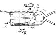
- a human fingersuch as the patient's index finger 12
- the bone that comprises the tip of the finger 12is commonly referred to as the third row phalange or the distal phalange 14 .
- the location of the joint between the distal phalange 14 and the second row phalange 16can be identified by the knuckle 18 on the top of the finger 12 and by the transverse fold 20 of skin on the bottom of the finger 12 .
- the emitter and detector components of conventional pulse oximetry sensorsare located close to the cuticle region of the fingernail, as indicated by the cuticle region 24 of the patient's index finger 12 . If the overall length L of the distal phalange 14 (covered with skin and other tissue) is defined to extend from the tip 22 of the finger 12 to the transverse fold 20 , then the cuticle region 24 extends from a transverse line spaced from the tip by about 35% of the length L to a transverse line spaced from the tip 22 by about 60% of the length L.
- each of the digits of the hand shown in the hand structure 10have unique vessel locations.
- the placement of a pulse oximetry sensor over a similar cuticle region 24 of these digitsmay result in different signal modulations unrelated to the underlying SaO 2 level, since these larger vessels are sufficiently opaque and, thus, may non-linearly contribute to the optical density of the tissue.
- small variations in the precise location of the sensor optics in the cuticle region 24 , or from digit-to-digit as illustrated in this hand structure 10may result in different detected light levels due, in part, to the varying contribution of the more opaque larger vasculature. In turn, this may impact the detected red-to-infrared modulation ratio and, consequently, the measured SpO 2 value.
- the distal region 26 of the index finger 12i.e., the area extending from the tip 22 to a transverse line spaced from the tip 22 by between about 20% to about 30% of the length L (approximately 5 mm to 7 mm from the tip for an average adult finger), includes few, if any, larger diameter arteries that may adversely affect pulse oximetry measurements. Indeed, it appears that the light from a pulse oximeter sensor will scatter through the tissue in the distal region 24 to probe the smaller arterioles and capillaries more uniformly, since the light fully penetrates these vessels.
- FIG. 3Aillustrates an exemplary pulse oximetry sensor 30 of this type.
- the sensor 30includes an emitter 32 and a detector 34 which may be of any suitable type.
- the emitter 32may be one or more light emitting diodes adapted to transmit one or more wavelengths of light in the red to infrared range
- the detector 34may be a photodetector selected to receive light in the range emitted from the emitter 32 .
- the emitter 32 and the detector 34may be disposed on a substrate 36 , which may be made of any suitable material, such as plastic, foam, woven material, or paper. Alternatively, the emitter 32 and the detector 34 may be located remotely and optically coupled to the sensor using optical fibers.
- the substrate 36may include an adhesive thereon to facilitate coupling of the sensor 30 to the distal region 26 of a patient, although alternative coupling arrangements are discussed below.
- the sensor 30is coupled to a cable 38 that is responsible for transmitting electrical and/or optical signals to and from the emitter 32 and detector 34 of the sensor 30 .
- the cable 38may be permanently coupled to the sensor 30 , or it may be removably coupled to the sensor 30 —the latter alternative being more useful and cost efficient in situations where the sensor 30 is disposable.
- the shunting device 30may be adapted to block light that may shunt directly between the emitter 32 and the detector 34 , i.e., light that does not travel through the blood perfused tissue of the finger 12 .
- An example of two possible shunting situationsis illustrated in FIG. 3B .
- a “type 1” shuntmay occur when light travels from the emitter 32 to the detector 34 through the substrate 36 , as illustrated by the wavy arrow 35 .
- a “type 2” shuntmay occur when light travels from the emitter 32 to the detector 34 by reflecting off of the finger 12 , as illustrated by the wavy arrow 37 .
- the type 1 shuntmay be addressed by placing a shunt barrier 39 in or on the substrate 36 between the emitter 32 and the detector 34 .
- the sensor 30may include regions that differ in the manner in which they reflect and/or absorb light from the emitter 32 .
- the region of the substrate 36 that extends from the emitter 32 to the detector 34may be a relatively light color, such as white, in order to enhance the reflectivity of the substrate 36 on the portion of the sensor 30 that is to be disposed on the distal region 26 of a patient's finger 12 .
- Portions 41 and 43 of the substrate 36 that extend on either side of the emitter 32 and the detector 34may be a darker, i.e., more absorptive, color, such as black.
- the darker portions 41 and 43 of the substrate 36will tend to absorb the light from the emitter 32 from portions of a patient's finger 12 that may fall outside of the distal region 26 so that the light is not collected by the detector 34 . Consequently, it is more likely that light detected by the detector 34 has passed through tissue in the distal region 26 of the patient's finger 12 as opposed to more proximal areas of the patient's finger 12 .
- the emitter 32 and detector 34 of the sensor 30may be placed in various positions in the distal region 26 and may operate in various modes, e.g., transmission or reflection. Examples of placement positions of the emitter 32 and the detector 34 on a patient's finger 12 are illustrated in FIGS. 4A , 4 B and 4 C, although it should be appreciated that the emitter 32 and the detector 34 may be similarly placed on a patient's toe as well.
- FIG. 4Ait can be seen that the emitter 32 is located on top of the finger 12 in the distal region 26 , while the detector 34 is located underneath, i.e., on the finger pad, of the finger 12 in the distal region 26 .
- the emitter 32may lie slightly on the fingernail 40 , slightly under the fingernail 40 , or on a fleshy portion of the tip of the finger 12 that may protrude past the fingernail 40 .
- the emitter 32 and detector 34can be arranged in a transmission mode so that the light from the emitter 32 shines vertically through the finger 12 to the detector 34 .
- the linear spacing between the center of the emitter 32 and the center of the detector 34 on the substrate 36would be in the range of about 10 mm to about 20 mm to ensure that the emitter 32 and the detector 34 are properly positioned in the distal region 26 of the patient's finger when the sensor 30 is applied.
- FIGS. 4B and 4CAlternate arrangements are illustrated in FIGS. 4B and 4C .
- the emitter 32 and the detector 34are both located underneath the finger 12 , i.e., on the finger pad, in the distal region 26 .
- FIG. 4Cit can be seen that the emitter 32 and the detector 34 are both located on the top of the finger 12 in the distal region 26 .
- the emitter 32 and the detector 34may both be placed slightly on the fingernail 40 , slightly underneath the fingernail 40 , or on the fleshy region of the tip of the finger 12 that may protrude past the fingernail 40 .
- the emitter 32 and the detector 34may be considered to operate in reflectance mode instead of transmission mode.
- the linear spacing between the center of the emitter 32 and the center of the detector 34 on the substrate 36would be in the range of about 5 mm to about 10 mm to ensure that the emitter 32 and the detector 34 are properly positioned in the distal region 26 of the patient's finger when the sensor 30 is applied.
- the locations of the emitter and the detectormay be swapped.
- the detector 34may be located at the top of the finger 12 and the emitter 32 may be located underneath the finger 12 .
- the componentsare located in the distal region 26 and perform in substantially the same manner.
- the sensor 30may be applied to a patient's finger or toe in any suitable manner.
- One manner of applicationincludes the use of an adhesive bandage 42 , as illustrated in FIGS. 5A and 5B .
- the back of the substrate 36is affixed to a portion of the adhesive bandage 42 so that the emitter 32 and detector 34 may be placed over the distal region 26 of the patient's finger 12 .
- the adhesive bandage 42may be wrapped over the entire finger, or it can be restricted to only a part of the finger.
- the adhesive bandage 42is applied primarily to the top of the finger 12 , where a portion of the bandage 42 extends along the cable 38 .
- the bandage 42is first adhered to the left side of the top of the patient's finger 12 , extended to the right of the finger 12 , around the distal region 26 , and over to the right side of the finger 12 in overlapping relationship with itself.
- the illustrated exampleis believed to be particularly useful, any other suitable configuration may also be used.
- the sensor 30may be secured to the distal region 26 of a patient's finger 12 by a non-adhesive wrap, a reusable wrap, or a clip.
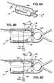
- FIGS. 6A , 6 B, and 6 COne example of a clip-style sensor 30 A is illustrated in FIGS. 6A , 6 B, and 6 C.
- the sensor 30 Ais illustrated as having two halves or portions.
- the sendor 30 Ais configured to operate in transmission mode, so the emitter resides in one half and the detector resides in the other half.
- the sensor 30 Amay be configured to operate in reflectance mode, in which case the emitter and the detector would reside in the same half or portion.
- the sensor 30 Ais spring loaded so that the sensor 30 A is biased in a closed position about a patient's finger 12 , as illustrated. As best seen in FIG.
- the sensor 30 Aincludes a stop 49 upon which a patient's finger 12 is intended to rest when the patient's finger 12 is properly inserted into the clip-style sensor 30 A.
- the emitter 32 and the detector 34lie in the distal region 26 of the patient's finger 12 .
- FIG. 6Cillustrates a clip-style sensor 51 having a stop 53 .
- the emitter 64 and the detector 66are located in the cuticle region 24 of the patient's finger 12 .
- the distance that the emitter and detector are spaced apart from the stopdictates whether the sensor is suitable for facilitating measurement in the distal region 26 or the cuticle region 24 .
- the sensor 30is typically adapted to be coupled directly to a pulse oximetry monitor 50 , as illustrated in FIG. 7 .
- the cable 38 of the sensor 30may be coupled to a transmission device (not shown) to facilitate wireless transmission between the sensor 30 and the monitor 50 .
- the monitor 50may be any suitable pulse oximeter, such as those available from Nellcor Puritan Bennett Inc.
- the monitor 50may be coupled to a multi-parameter patient monitor or other pulse oximetry monitor 52 via a cable 54 connected to a sensor input port or via a cable 55 connected to a digital communication port.
- the emitter 32will transmit the selected wavelength(s) of light into the distal region 26 of the patient's finger 12 and the detector 34 will detect light from the distal region 26 of the patient's finger 12 .
- the photon distribution 60illustrates the amount of light emitted from the emitter 32 that passes through various portions of the patient's finger 12 and that is detected by the detector 34 .
- the photon distribution 60is a graphical representation of where the photons from the emitter 32 travel through the tissue for ultimate receipt by the detector 34 .
- the emitter 32 and detector 34located in the distal region 26 of the patient's finger 12 , it can be seen that the majority of the photons received by the detector 34 pass through the distal region 26 , with a minority of the photons received by the detector 34 passing through the cuticle region 24 . Indeed, it is estimated that at least approximately 50% to 80%, and possibly 90% or more, of the light received by the detector 34 has passed through the distal region 26 when the sensor 30 is located in the distal region 26 of the patient's finger 12 .
- FIG. 8Billustrates a photon distribution 62 created by a conventional sensor located in the cuticle region 24 of a patient's finger.
- the photon distribution 62illustrates the amount of light emitted from an emitter 64 that passes through various portions of the patient's finger 12 and that is detected by a detector 66 .
- the photon distribution 62is a graphical representation of where the photons from the emitter 64 travel through the tissue for ultimate receipt by the detector 66 .
- the emitter 64 and detector 66located in the cuticle region 24 of the patient's finger 12 , it can be seen that the majority of the photons received by the detector 66 pass through the cuticle region 24 , with a minority of the photons received by the detector 66 passing through the distal region 26 . Indeed, it is estimated that approximately 65% to 85% of the light received by the detector 66 has passed through the cuticle region 24 when the sensor is located in the cuticle region 24 of the patient's finger 12 , whereas only approximately 15% to 35% of the light received by the detector 66 has passed through the distal region 26 .
- the placement of an emitter and detector in the distal region 26 of a patient's finger 12results in much more of the detected light having passed through the well-perfused and relatively unoccluded tissue of the distal region 26 , as opposed to the relatively occluded tissue of the cuticle region 24 , when compared with the placement of an emitter and detector in the conventional cuticle region 24 of a patent's finger.
- the collected lightpresumably correlates better with the characteristics of the blood that the pulse oximeter 50 is attempting to measure, since the collected light is not as adversely affected by strongly light-absorbing or scattering structures, such as bones and larger blood vessels.
- the present drawingsillustrate the emitter 32 and the detector 34 as being wholly located in the distal region 26 , it should be noted that similar results will likely follow so long as the center points of the emitter 32 and detector 34 are located in the distal region 26 even though a portion of the emitter 32 and/or detector 34 might lie in the cuticle region 24 . Indeed, in a possible embodiment in which the emitter 32 and/or the detector 34 have relatively large diameters, in the range of about 5 mm to about 10 mm for example, a portion of the emitter 32 and/or detector 34 might lie in the cuticle region 24 , even though the emitter 32 and the detector 34 are centered over the distal region 26 . Nevertheless, it is believed that such a sensor placement would result in benefits similar to those discussed above in embodiments in which the emitter 32 and the detector 34 are wholly located in the distal region 26 without extending into the cuticle region 24 .
- the senor 30 / 30 Amay be provided with portions of light absorbing material in the areas of the sensor 30 / 30 A proximate to the cuticle region 24 and portions of relatively reflective material in portions of the sensor 30 / 30 A proximate to the distal region 26 .
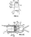
- FIG. 3Dillustrates a sensor 30 having portions 41 and 43 of relatively light absorbing material to facilitate such an improvement in photon distribution in the distal region 26 .
- FIG. 8Cillustrates a clip-style sensor 30 A that includes portions 67 and 69 of relatively light absorbing material that extends along the portions of the sensor 30 A that are proximate the cuticle region 24 .
- the portions 67 and 69 of light absorbing materialgreatly reduce the amount of light from the emitter 32 that passes through the cuticle region 24 to be received by the detector 34 .
- the collected lightpresumably correlates better with the characteristics of the blood that the pulse oximeter 50 is attempting to measure, since the collected light is not as adversely effected by structures in the cuticle region 24 of the patient's finger 12 .
- the emittermay be shaped to enhance the concentration of photons delivered to the distal region 26 .
- the emitter/aperture 32 Ais illustrated. As can be seen, the emitter/aperture 32 A is shaped so that it extends laterally across the distal region 26 to deliver photons having a distribution pattern that is more focused and better distributed within the distal region 26 as compared with a round emitter/aperture.
Landscapes
- Health & Medical Sciences (AREA)
- Life Sciences & Earth Sciences (AREA)
- Physics & Mathematics (AREA)
- Biomedical Technology (AREA)
- Medical Informatics (AREA)
- Biophysics (AREA)
- Pathology (AREA)
- Engineering & Computer Science (AREA)
- Veterinary Medicine (AREA)
- Heart & Thoracic Surgery (AREA)
- Public Health (AREA)
- Molecular Biology (AREA)
- Surgery (AREA)
- Animal Behavior & Ethology (AREA)
- General Health & Medical Sciences (AREA)
- Optics & Photonics (AREA)
- Spectroscopy & Molecular Physics (AREA)
- Measurement Of The Respiration, Hearing Ability, Form, And Blood Characteristics Of Living Organisms (AREA)
Abstract
Description
Claims (32)
Priority Applications (2)
| Application Number | Priority Date | Filing Date | Title |
|---|---|---|---|
| US11/096,009US7548771B2 (en) | 2005-03-31 | 2005-03-31 | Pulse oximetry sensor and technique for using the same on a distal region of a patient's digit |
| PCT/US2006/010332WO2006104790A1 (en) | 2005-03-31 | 2006-03-21 | Pulse oximetry sensor and technique for using the same on a distal region of a patient's digit |
Applications Claiming Priority (1)
| Application Number | Priority Date | Filing Date | Title |
|---|---|---|---|
| US11/096,009US7548771B2 (en) | 2005-03-31 | 2005-03-31 | Pulse oximetry sensor and technique for using the same on a distal region of a patient's digit |
Publications (2)
| Publication Number | Publication Date |
|---|---|
| US20060224058A1 US20060224058A1 (en) | 2006-10-05 |
| US7548771B2true US7548771B2 (en) | 2009-06-16 |
Family
ID=36603591
Family Applications (1)
| Application Number | Title | Priority Date | Filing Date |
|---|---|---|---|
| US11/096,009Active2026-07-31US7548771B2 (en) | 2005-03-31 | 2005-03-31 | Pulse oximetry sensor and technique for using the same on a distal region of a patient's digit |
Country Status (2)
| Country | Link |
|---|---|
| US (1) | US7548771B2 (en) |
| WO (1) | WO2006104790A1 (en) |
Cited By (4)
| Publication number | Priority date | Publication date | Assignee | Title |
|---|---|---|---|---|
| US20100182126A1 (en)* | 2008-12-18 | 2010-07-22 | Martis Dinesh J | Biometric sensing apparatus and methods incorporating the same |
| US20100331635A1 (en)* | 2008-05-20 | 2010-12-30 | Beijing Choice Electronic Technology Co., Ltd. | Finger-Clipped Oximeter with Finger Pressed Plate |
| US9833146B2 (en) | 2012-04-17 | 2017-12-05 | Covidien Lp | Surgical system and method of use of the same |
| US20220313473A1 (en)* | 2019-06-26 | 2022-10-06 | Coloplast A/S | Device for connecting a base plate and/or a sensor patch for a medical device |
Families Citing this family (108)
| Publication number | Priority date | Publication date | Assignee | Title |
|---|---|---|---|---|
| US6018673A (en) | 1996-10-10 | 2000-01-25 | Nellcor Puritan Bennett Incorporated | Motion compatible sensor for non-invasive optical blood analysis |
| US20060161071A1 (en) | 1997-01-27 | 2006-07-20 | Lynn Lawrence A | Time series objectification system and method |
| US9042952B2 (en) | 1997-01-27 | 2015-05-26 | Lawrence A. Lynn | System and method for automatic detection of a plurality of SPO2 time series pattern types |
| US8932227B2 (en) | 2000-07-28 | 2015-01-13 | Lawrence A. Lynn | System and method for CO2 and oximetry integration |
| US9521971B2 (en) | 1997-07-14 | 2016-12-20 | Lawrence A. Lynn | System and method for automatic detection of a plurality of SPO2 time series pattern types |
| US20070191697A1 (en) | 2006-02-10 | 2007-08-16 | Lynn Lawrence A | System and method for SPO2 instability detection and quantification |
| US6675031B1 (en) | 1999-04-14 | 2004-01-06 | Mallinckrodt Inc. | Method and circuit for indicating quality and accuracy of physiological measurements |
| US9053222B2 (en) | 2002-05-17 | 2015-06-09 | Lawrence A. Lynn | Patient safety processor |
| US20060195041A1 (en) | 2002-05-17 | 2006-08-31 | Lynn Lawrence A | Centralized hospital monitoring system for automatically detecting upper airway instability and for preventing and aborting adverse drug reactions |
| US6754516B2 (en) | 2001-07-19 | 2004-06-22 | Nellcor Puritan Bennett Incorporated | Nuisance alarm reductions in a physiological monitor |
| US7190986B1 (en) | 2002-10-18 | 2007-03-13 | Nellcor Puritan Bennett Inc. | Non-adhesive oximeter sensor for sensitive skin |
| US7006856B2 (en) | 2003-01-10 | 2006-02-28 | Nellcor Puritan Bennett Incorporated | Signal quality metrics design for qualifying data for a physiological monitor |
| US7016715B2 (en) | 2003-01-13 | 2006-03-21 | Nellcorpuritan Bennett Incorporated | Selection of preset filter parameters based on signal quality |
| US7190985B2 (en) | 2004-02-25 | 2007-03-13 | Nellcor Puritan Bennett Inc. | Oximeter ambient light cancellation |
| US7120479B2 (en) | 2004-02-25 | 2006-10-10 | Nellcor Puritan Bennett Inc. | Switch-mode oximeter LED drive with a single inductor |
| US7534212B2 (en) | 2004-03-08 | 2009-05-19 | Nellcor Puritan Bennett Llc | Pulse oximeter with alternate heart-rate determination |
| US7194293B2 (en) | 2004-03-08 | 2007-03-20 | Nellcor Puritan Bennett Incorporated | Selection of ensemble averaging weights for a pulse oximeter based on signal quality metrics |
| US7679519B2 (en) | 2004-11-05 | 2010-03-16 | Envitec-Wismar Gmbh | Apparatus for improved pulse oximetry measurement |
| US7392075B2 (en) | 2005-03-03 | 2008-06-24 | Nellcor Puritan Bennett Incorporated | Method for enhancing pulse oximetry calculations in the presence of correlated artifacts |
| US7590439B2 (en) | 2005-08-08 | 2009-09-15 | Nellcor Puritan Bennett Llc | Bi-stable medical sensor and technique for using the same |
| US7657294B2 (en) | 2005-08-08 | 2010-02-02 | Nellcor Puritan Bennett Llc | Compliant diaphragm medical sensor and technique for using the same |
| US7904130B2 (en) | 2005-09-29 | 2011-03-08 | Nellcor Puritan Bennett Llc | Medical sensor and technique for using the same |
| US7725146B2 (en) | 2005-09-29 | 2010-05-25 | Nellcor Puritan Bennett Llc | System and method for pre-processing waveforms |
| US8092379B2 (en) | 2005-09-29 | 2012-01-10 | Nellcor Puritan Bennett Llc | Method and system for determining when to reposition a physiological sensor |
| US7725147B2 (en) | 2005-09-29 | 2010-05-25 | Nellcor Puritan Bennett Llc | System and method for removing artifacts from waveforms |
| US7899510B2 (en)* | 2005-09-29 | 2011-03-01 | Nellcor Puritan Bennett Llc | Medical sensor and technique for using the same |
| US7483731B2 (en) | 2005-09-30 | 2009-01-27 | Nellcor Puritan Bennett Llc | Medical sensor and technique for using the same |
| US7555327B2 (en) | 2005-09-30 | 2009-06-30 | Nellcor Puritan Bennett Llc | Folding medical sensor and technique for using the same |
| US20070106126A1 (en) | 2005-09-30 | 2007-05-10 | Mannheimer Paul D | Patient monitoring alarm escalation system and method |
| US8233954B2 (en) | 2005-09-30 | 2012-07-31 | Nellcor Puritan Bennett Llc | Mucosal sensor for the assessment of tissue and blood constituents and technique for using the same |
| US8062221B2 (en) | 2005-09-30 | 2011-11-22 | Nellcor Puritan Bennett Llc | Sensor for tissue gas detection and technique for using the same |
| US7486979B2 (en) | 2005-09-30 | 2009-02-03 | Nellcor Puritan Bennett Llc | Optically aligned pulse oximetry sensor and technique for using the same |
| US7668579B2 (en) | 2006-02-10 | 2010-02-23 | Lynn Lawrence A | System and method for the detection of physiologic response to stimulation |
| US8702606B2 (en) | 2006-03-21 | 2014-04-22 | Covidien Lp | Patient monitoring help video system and method |
| US8380271B2 (en) | 2006-06-15 | 2013-02-19 | Covidien Lp | System and method for generating customizable audible beep tones and alarms |
| US8145288B2 (en) | 2006-08-22 | 2012-03-27 | Nellcor Puritan Bennett Llc | Medical sensor for reducing signal artifacts and technique for using the same |
| US8219170B2 (en) | 2006-09-20 | 2012-07-10 | Nellcor Puritan Bennett Llc | System and method for practicing spectrophotometry using light emitting nanostructure devices |
| US7574245B2 (en) | 2006-09-27 | 2009-08-11 | Nellcor Puritan Bennett Llc | Flexible medical sensor enclosure |
| US7890153B2 (en) | 2006-09-28 | 2011-02-15 | Nellcor Puritan Bennett Llc | System and method for mitigating interference in pulse oximetry |
| US8175667B2 (en) | 2006-09-29 | 2012-05-08 | Nellcor Puritan Bennett Llc | Symmetric LED array for pulse oximetry |
| US7680522B2 (en) | 2006-09-29 | 2010-03-16 | Nellcor Puritan Bennett Llc | Method and apparatus for detecting misapplied sensors |
| US8068891B2 (en) | 2006-09-29 | 2011-11-29 | Nellcor Puritan Bennett Llc | Symmetric LED array for pulse oximetry |
| US7476131B2 (en) | 2006-09-29 | 2009-01-13 | Nellcor Puritan Bennett Llc | Device for reducing crosstalk |
| US8728059B2 (en) | 2006-09-29 | 2014-05-20 | Covidien Lp | System and method for assuring validity of monitoring parameter in combination with a therapeutic device |
| US8068890B2 (en) | 2006-09-29 | 2011-11-29 | Nellcor Puritan Bennett Llc | Pulse oximetry sensor switchover |
| CN100448398C (en)* | 2006-11-27 | 2009-01-07 | 北京超思电子技术有限责任公司 | A finger-clipped saturation oxygen measuring apparatus |
| US8204567B2 (en) | 2007-12-13 | 2012-06-19 | Nellcor Puritan Bennett Llc | Signal demodulation |
| US8366613B2 (en) | 2007-12-26 | 2013-02-05 | Covidien Lp | LED drive circuit for pulse oximetry and method for using same |
| US8577434B2 (en) | 2007-12-27 | 2013-11-05 | Covidien Lp | Coaxial LED light sources |
| US8442608B2 (en) | 2007-12-28 | 2013-05-14 | Covidien Lp | System and method for estimating physiological parameters by deconvolving artifacts |
| US8452364B2 (en) | 2007-12-28 | 2013-05-28 | Covidien LLP | System and method for attaching a sensor to a patient's skin |
| US8070508B2 (en) | 2007-12-31 | 2011-12-06 | Nellcor Puritan Bennett Llc | Method and apparatus for aligning and securing a cable strain relief |
| US8897850B2 (en) | 2007-12-31 | 2014-11-25 | Covidien Lp | Sensor with integrated living hinge and spring |
| US8199007B2 (en) | 2007-12-31 | 2012-06-12 | Nellcor Puritan Bennett Llc | Flex circuit snap track for a biometric sensor |
| US8092993B2 (en) | 2007-12-31 | 2012-01-10 | Nellcor Puritan Bennett Llc | Hydrogel thin film for use as a biosensor |
| US8275553B2 (en) | 2008-02-19 | 2012-09-25 | Nellcor Puritan Bennett Llc | System and method for evaluating physiological parameter data |
| US8750953B2 (en) | 2008-02-19 | 2014-06-10 | Covidien Lp | Methods and systems for alerting practitioners to physiological conditions |
| US8140272B2 (en) | 2008-03-27 | 2012-03-20 | Nellcor Puritan Bennett Llc | System and method for unmixing spectroscopic observations with nonnegative matrix factorization |
| US8437822B2 (en) | 2008-03-28 | 2013-05-07 | Covidien Lp | System and method for estimating blood analyte concentration |
| US8292809B2 (en) | 2008-03-31 | 2012-10-23 | Nellcor Puritan Bennett Llc | Detecting chemical components from spectroscopic observations |
| US8364224B2 (en) | 2008-03-31 | 2013-01-29 | Covidien Lp | System and method for facilitating sensor and monitor communication |
| US8112375B2 (en) | 2008-03-31 | 2012-02-07 | Nellcor Puritan Bennett Llc | Wavelength selection and outlier detection in reduced rank linear models |
| JP5474937B2 (en) | 2008-05-07 | 2014-04-16 | ローレンス エー. リン, | Medical disorder pattern search engine |
| US7880884B2 (en) | 2008-06-30 | 2011-02-01 | Nellcor Puritan Bennett Llc | System and method for coating and shielding electronic sensor components |
| US9895068B2 (en) | 2008-06-30 | 2018-02-20 | Covidien Lp | Pulse oximeter with wait-time indication |
| US8071935B2 (en) | 2008-06-30 | 2011-12-06 | Nellcor Puritan Bennett Llc | Optical detector with an overmolded faraday shield |
| US7887345B2 (en) | 2008-06-30 | 2011-02-15 | Nellcor Puritan Bennett Llc | Single use connector for pulse oximetry sensors |
| USD626561S1 (en) | 2008-06-30 | 2010-11-02 | Nellcor Puritan Bennett Llc | Circular satseconds indicator and triangular saturation pattern detection indicator for a patient monitor display panel |
| USD626562S1 (en) | 2008-06-30 | 2010-11-02 | Nellcor Puritan Bennett Llc | Triangular saturation pattern detection indicator for a patient monitor display panel |
| US8364220B2 (en) | 2008-09-25 | 2013-01-29 | Covidien Lp | Medical sensor and technique for using the same |
| US8433382B2 (en) | 2008-09-30 | 2013-04-30 | Covidien Lp | Transmission mode photon density wave system and method |
| US8914088B2 (en) | 2008-09-30 | 2014-12-16 | Covidien Lp | Medical sensor and technique for using the same |
| US8386000B2 (en) | 2008-09-30 | 2013-02-26 | Covidien Lp | System and method for photon density wave pulse oximetry and pulse hemometry |
| US8423112B2 (en) | 2008-09-30 | 2013-04-16 | Covidien Lp | Medical sensor and technique for using the same |
| US8968193B2 (en) | 2008-09-30 | 2015-03-03 | Covidien Lp | System and method for enabling a research mode on physiological monitors |
| US8417309B2 (en) | 2008-09-30 | 2013-04-09 | Covidien Lp | Medical sensor |
| EP2395907A4 (en)* | 2009-02-13 | 2015-04-22 | Hutchinson Technology | Portable sto2 spectrometer |
| US8452366B2 (en) | 2009-03-16 | 2013-05-28 | Covidien Lp | Medical monitoring device with flexible circuitry |
| US8221319B2 (en) | 2009-03-25 | 2012-07-17 | Nellcor Puritan Bennett Llc | Medical device for assessing intravascular blood volume and technique for using the same |
| US8509869B2 (en) | 2009-05-15 | 2013-08-13 | Covidien Lp | Method and apparatus for detecting and analyzing variations in a physiologic parameter |
| US8634891B2 (en) | 2009-05-20 | 2014-01-21 | Covidien Lp | Method and system for self regulation of sensor component contact pressure |
| US8311601B2 (en) | 2009-06-30 | 2012-11-13 | Nellcor Puritan Bennett Llc | Reflectance and/or transmissive pulse oximeter |
| US9010634B2 (en) | 2009-06-30 | 2015-04-21 | Covidien Lp | System and method for linking patient data to a patient and providing sensor quality assurance |
| US8505821B2 (en) | 2009-06-30 | 2013-08-13 | Covidien Lp | System and method for providing sensor quality assurance |
| US8391941B2 (en) | 2009-07-17 | 2013-03-05 | Covidien Lp | System and method for memory switching for multiple configuration medical sensor |
| US8494786B2 (en) | 2009-07-30 | 2013-07-23 | Covidien Lp | Exponential sampling of red and infrared signals |
| US8417310B2 (en) | 2009-08-10 | 2013-04-09 | Covidien Lp | Digital switching in multi-site sensor |
| US8494606B2 (en) | 2009-08-19 | 2013-07-23 | Covidien Lp | Photoplethysmography with controlled application of sensor pressure |
| US8428675B2 (en) | 2009-08-19 | 2013-04-23 | Covidien Lp | Nanofiber adhesives used in medical devices |
| US8704666B2 (en) | 2009-09-21 | 2014-04-22 | Covidien Lp | Medical device interface customization systems and methods |
| US8788001B2 (en) | 2009-09-21 | 2014-07-22 | Covidien Lp | Time-division multiplexing in a multi-wavelength photon density wave system |
| US8494604B2 (en) | 2009-09-21 | 2013-07-23 | Covidien Lp | Wavelength-division multiplexing in a multi-wavelength photon density wave system |
| US8798704B2 (en) | 2009-09-24 | 2014-08-05 | Covidien Lp | Photoacoustic spectroscopy method and system to discern sepsis from shock |
| US8515511B2 (en) | 2009-09-29 | 2013-08-20 | Covidien Lp | Sensor with an optical coupling material to improve plethysmographic measurements and method of using the same |
| US9554739B2 (en) | 2009-09-29 | 2017-01-31 | Covidien Lp | Smart cable for coupling a medical sensor to an electronic patient monitor |
| US8376955B2 (en) | 2009-09-29 | 2013-02-19 | Covidien Lp | Spectroscopic method and system for assessing tissue temperature |
| US8930145B2 (en) | 2010-07-28 | 2015-01-06 | Covidien Lp | Light focusing continuous wave photoacoustic spectroscopy and its applications to patient monitoring |
| WO2013023037A2 (en)* | 2011-08-09 | 2013-02-14 | Lemm Technologies, Llc | Device and method for measuring an analyte under the nail |
| WO2014143412A1 (en)* | 2013-03-13 | 2014-09-18 | Devicearm, Inc. | Method and apparatus for antimicrobial treatment |
| US10905361B2 (en) | 2013-05-06 | 2021-02-02 | Promedica Health System, Inc. | Radial check device |
| WO2014182609A1 (en)* | 2013-05-06 | 2014-11-13 | Promedica Health System, Inc. | Radial check device |
| US9597021B1 (en) | 2014-01-14 | 2017-03-21 | Analytics For Life | Noninvasive method for estimating glucose, glycosylated hemoglobin and other blood constituents |
| US10165955B2 (en)* | 2014-02-06 | 2019-01-01 | Reuven Gladshtein | Obtaining cardiovascular parameters using arterioles related transient time |
| CN105266773B (en)* | 2015-11-04 | 2018-07-27 | 上海箩箕技术有限公司 | Pulse wave sensor and wearable electronic |
| US10646144B2 (en)* | 2015-12-07 | 2020-05-12 | Marcelo Malini Lamego | Wireless, disposable, extended use pulse oximeter apparatus and methods |
| WO2018085625A1 (en) | 2016-11-03 | 2018-05-11 | Basil Leaf Technologies, Llc | Non-invasive blood glucose sensor |
| US10659963B1 (en) | 2018-02-12 | 2020-05-19 | True Wearables, Inc. | Single use medical device apparatus and methods |
| CN114073521A (en)* | 2020-08-17 | 2022-02-22 | 深圳迈瑞生物医疗电子股份有限公司 | Blood oxygen sensor assembly and blood oxygen measuring device |
Citations (15)
| Publication number | Priority date | Publication date | Assignee | Title |
|---|---|---|---|---|
| US4685464A (en)* | 1985-07-05 | 1987-08-11 | Nellcor Incorporated | Durable sensor for detecting optical pulses |
| US4830014A (en) | 1983-05-11 | 1989-05-16 | Nellcor Incorporated | Sensor having cutaneous conformance |
| US5246003A (en)* | 1991-08-28 | 1993-09-21 | Nellcor Incorporated | Disposable pulse oximeter sensor |
| US5490523A (en) | 1994-06-29 | 1996-02-13 | Nonin Medical Inc. | Finger clip pulse oximeter |
| EP0781527A1 (en) | 1995-11-29 | 1997-07-02 | Instrumentarium Oy | Pulsoximeter sensor |
| US5776059A (en) | 1995-11-08 | 1998-07-07 | Hewlett-Packard Company | Sensor for performing medical measurements, particularly pulsoximetry measurements on the human finger |
| US5810724A (en)* | 1995-12-01 | 1998-09-22 | Nellcor Puritan Bennett Incorporated | Reusable sensor accessory containing a conformable spring activated rubber sleeved clip |
| US5830136A (en)* | 1996-10-31 | 1998-11-03 | Nellcor Puritan Bennett Incorporated | Gel pad optical sensor |
| US5924982A (en)* | 1997-07-30 | 1999-07-20 | Nellcor Puritan Bennett Incorporated | Oximeter sensor with user-modifiable color surface |
| US6018673A (en)* | 1996-10-10 | 2000-01-25 | Nellcor Puritan Bennett Incorporated | Motion compatible sensor for non-invasive optical blood analysis |
| US6115621A (en)* | 1997-07-30 | 2000-09-05 | Nellcor Puritan Bennett Incorporated | Oximetry sensor with offset emitters and detector |
| EP1222894A2 (en) | 2001-01-11 | 2002-07-17 | Sensidyne, Inc. | Reusable pulse oximeter probe and disposable bandage method |
| US20020115919A1 (en)* | 1999-12-09 | 2002-08-22 | Ammar Al-Ali | Resposable pulse oximetry sensor |
| US6697656B1 (en)* | 2000-06-27 | 2004-02-24 | Masimo Corporation | Pulse oximetry sensor compatible with multiple pulse oximetry systems |
| US20070073124A1 (en)* | 2005-09-29 | 2007-03-29 | Li Li | System and method for removing artifacts from waveforms |
- 2005
- 2005-03-31USUS11/096,009patent/US7548771B2/enactiveActive
- 2006
- 2006-03-21WOPCT/US2006/010332patent/WO2006104790A1/enactiveApplication Filing
Patent Citations (22)
| Publication number | Priority date | Publication date | Assignee | Title |
|---|---|---|---|---|
| US4830014A (en) | 1983-05-11 | 1989-05-16 | Nellcor Incorporated | Sensor having cutaneous conformance |
| US4685464A (en)* | 1985-07-05 | 1987-08-11 | Nellcor Incorporated | Durable sensor for detecting optical pulses |
| US5246003A (en)* | 1991-08-28 | 1993-09-21 | Nellcor Incorporated | Disposable pulse oximeter sensor |
| US5469845A (en)* | 1991-08-28 | 1995-11-28 | Nellcor Incorporated | Disposable pulse oximeter sensor |
| US5678544A (en)* | 1991-08-28 | 1997-10-21 | Nellcor Puritan Bennett Incorporated | Disposable pulse oximeter sensor |
| US5490523A (en) | 1994-06-29 | 1996-02-13 | Nonin Medical Inc. | Finger clip pulse oximeter |
| US5776059A (en) | 1995-11-08 | 1998-07-07 | Hewlett-Packard Company | Sensor for performing medical measurements, particularly pulsoximetry measurements on the human finger |
| EP0781527A1 (en) | 1995-11-29 | 1997-07-02 | Instrumentarium Oy | Pulsoximeter sensor |
| US5810724A (en)* | 1995-12-01 | 1998-09-22 | Nellcor Puritan Bennett Incorporated | Reusable sensor accessory containing a conformable spring activated rubber sleeved clip |
| US20020103423A1 (en) | 1996-10-10 | 2002-08-01 | Nellcor Puritan Bennett Incorporated | Motion compatible sensor for non-invasive optical blood analysis |
| US6018673A (en)* | 1996-10-10 | 2000-01-25 | Nellcor Puritan Bennett Incorporated | Motion compatible sensor for non-invasive optical blood analysis |
| US6374129B1 (en)* | 1996-10-10 | 2002-04-16 | Nellocr Puritan Bennett Incorporated | Motion compatible sensor for non-invasive optical blood analysis |
| US6845256B2 (en)* | 1996-10-10 | 2005-01-18 | Nellcor Puritan Bennett Incorporated | Motion compatible sensor for non-invasive optical blood analysis |
| US20050070773A1 (en)* | 1996-10-10 | 2005-03-31 | Nellcor Puritan Bennett Incorporated | Motion compatible sensor for non-invasive optical blood analysis |
| US7260425B2 (en)* | 1996-10-10 | 2007-08-21 | Nellcor Puritan Bennett Incorporated | Motion compatible sensor for non-invasive optical blood analysis |
| US5830136A (en)* | 1996-10-31 | 1998-11-03 | Nellcor Puritan Bennett Incorporated | Gel pad optical sensor |
| US5924982A (en)* | 1997-07-30 | 1999-07-20 | Nellcor Puritan Bennett Incorporated | Oximeter sensor with user-modifiable color surface |
| US6115621A (en)* | 1997-07-30 | 2000-09-05 | Nellcor Puritan Bennett Incorporated | Oximetry sensor with offset emitters and detector |
| US20020115919A1 (en)* | 1999-12-09 | 2002-08-22 | Ammar Al-Ali | Resposable pulse oximetry sensor |
| US6697656B1 (en)* | 2000-06-27 | 2004-02-24 | Masimo Corporation | Pulse oximetry sensor compatible with multiple pulse oximetry systems |
| EP1222894A2 (en) | 2001-01-11 | 2002-07-17 | Sensidyne, Inc. | Reusable pulse oximeter probe and disposable bandage method |
| US20070073124A1 (en)* | 2005-09-29 | 2007-03-29 | Li Li | System and method for removing artifacts from waveforms |
Cited By (5)
| Publication number | Priority date | Publication date | Assignee | Title |
|---|---|---|---|---|
| US20100331635A1 (en)* | 2008-05-20 | 2010-12-30 | Beijing Choice Electronic Technology Co., Ltd. | Finger-Clipped Oximeter with Finger Pressed Plate |
| US8369917B2 (en)* | 2008-05-20 | 2013-02-05 | Beijing Choice Electronic Technology Co., Ltd. | Finger-clipped oximeter with finger pressed plate |
| US20100182126A1 (en)* | 2008-12-18 | 2010-07-22 | Martis Dinesh J | Biometric sensing apparatus and methods incorporating the same |
| US9833146B2 (en) | 2012-04-17 | 2017-12-05 | Covidien Lp | Surgical system and method of use of the same |
| US20220313473A1 (en)* | 2019-06-26 | 2022-10-06 | Coloplast A/S | Device for connecting a base plate and/or a sensor patch for a medical device |
Also Published As
| Publication number | Publication date |
|---|---|
| US20060224058A1 (en) | 2006-10-05 |
| WO2006104790A1 (en) | 2006-10-05 |
Similar Documents
| Publication | Publication Date | Title |
|---|---|---|
| US7548771B2 (en) | Pulse oximetry sensor and technique for using the same on a distal region of a patient's digit | |
| US7899510B2 (en) | Medical sensor and technique for using the same | |
| US8145288B2 (en) | Medical sensor for reducing signal artifacts and technique for using the same | |
| US8818476B2 (en) | Reflectance and/or transmissive pulse oximeter | |
| JP4903980B2 (en) | Pulse oximeter and operation method thereof | |
| CA2753018C (en) | Medical sensor with flexible components and technique for using the same | |
| US7680522B2 (en) | Method and apparatus for detecting misapplied sensors | |
| Mannheimer | The light–tissue interaction of pulse oximetry | |
| US8805463B2 (en) | Medical sensor with compressible light barrier and technique for using the same | |
| US8437826B2 (en) | Clip-style medical sensor and technique for using the same | |
| US8515512B2 (en) | Opaque, electrically nonconductive region on a medical sensor | |
| US8423112B2 (en) | Medical sensor and technique for using the same | |
| US8126525B2 (en) | Probe and a method for use with a probe | |
| WO2000002483A2 (en) | Fetal pulse oximetry sensor | |
| US20080064940A1 (en) | Sensor cable design for use with spectrophotometric sensors and method of using the same | |
| US8588879B2 (en) | Motion compensation in a sensor | |
| US20070265513A1 (en) | Optical measurement of mitochondrial function in blood perfused tissue | |
| US8417310B2 (en) | Digital switching in multi-site sensor | |
| US20090171172A1 (en) | Method and system for pulse gating |
Legal Events
| Date | Code | Title | Description |
|---|---|---|---|
| AS | Assignment | Owner name:NELLCOR PURITAN BENNETT INCORPORATED, CALIFORNIA Free format text:ASSIGNMENT OF ASSIGNORS INTEREST;ASSIGNOR:MANNHEIMER, PAUL D.;REEL/FRAME:017338/0039 Effective date:20050624 | |
| AS | Assignment | Owner name:NELLCOR PURITAN BENNETT LLC, COLORADO Free format text:CHANGE OF NAME;ASSIGNOR:MANNHEIMER, PAUL D.;REEL/FRAME:022636/0889 Effective date:20050622 | |
| STCF | Information on status: patent grant | Free format text:PATENTED CASE | |
| AS | Assignment | Owner name:NELLCOR PURITAN BENNETT LLC, COLORADO Free format text:CORRECTIVE ASSIGNMENT TO CORRECT THE EXECUTION DATE THAT INVENTOR, PAUL D. MANNHEIMER, SIGNED THE ASSIGNMENT PREVIOUSLY RECORDED ON REEL 022636 FRAME 0889;ASSIGNOR:MANNHEIMER, PAUL D.;REEL/FRAME:023015/0054 Effective date:20050624 | |
| AS | Assignment | Owner name:COVIDIEN LP, MASSACHUSETTS Free format text:ASSIGNMENT OF ASSIGNORS INTEREST;ASSIGNOR:NELLCOR PURITAN BENNETT LLC;REEL/FRAME:029345/0117 Effective date:20120929 | |
| FPAY | Fee payment | Year of fee payment:4 | |
| FPAY | Fee payment | Year of fee payment:8 | |
| MAFP | Maintenance fee payment | Free format text:PAYMENT OF MAINTENANCE FEE, 12TH YEAR, LARGE ENTITY (ORIGINAL EVENT CODE: M1553); ENTITY STATUS OF PATENT OWNER: LARGE ENTITY Year of fee payment:12 |