US7547382B2 - Determination of partial fill in electrochemical strips - Google Patents
Determination of partial fill in electrochemical stripsDownload PDFInfo
- Publication number
- US7547382B2 US7547382B2US10/907,813US90781305AUS7547382B2US 7547382 B2US7547382 B2US 7547382B2US 90781305 AUS90781305 AUS 90781305AUS 7547382 B2US7547382 B2US 7547382B2
- Authority
- US
- United States
- Prior art keywords
- current
- double layer
- potential
- time
- determined
- Prior art date
- Legal status (The legal status is an assumption and is not a legal conclusion. Google has not performed a legal analysis and makes no representation as to the accuracy of the status listed.)
- Active, expires
Links
- 0CC(C)CC(CC1C(C)C2)C3C[C@@]1C2(*)CC3Chemical compoundCC(C)CC(CC1C(C)C2)C3C[C@@]1C2(*)CC30.000description1
Images


Classifications
- G—PHYSICS
- G01—MEASURING; TESTING
- G01N—INVESTIGATING OR ANALYSING MATERIALS BY DETERMINING THEIR CHEMICAL OR PHYSICAL PROPERTIES
- G01N27/00—Investigating or analysing materials by the use of electric, electrochemical, or magnetic means
- G01N27/26—Investigating or analysing materials by the use of electric, electrochemical, or magnetic means by investigating electrochemical variables; by using electrolysis or electrophoresis
- G01N27/28—Electrolytic cell components
- G01N27/30—Electrodes, e.g. test electrodes; Half-cells
- G01N27/327—Biochemical electrodes, e.g. electrical or mechanical details for in vitro measurements
- G—PHYSICS
- G01—MEASURING; TESTING
- G01N—INVESTIGATING OR ANALYSING MATERIALS BY DETERMINING THEIR CHEMICAL OR PHYSICAL PROPERTIES
- G01N33/00—Investigating or analysing materials by specific methods not covered by groups G01N1/00 - G01N31/00
- G01N33/48—Biological material, e.g. blood, urine; Haemocytometers
- G01N33/483—Physical analysis of biological material
- G01N33/487—Physical analysis of biological material of liquid biological material
Definitions
- This applicationrelates to a method for detecting partial fill in an electrochemical test strip, and to a meter, and meter-test strip combination for use in such a method.
- test stripsare frequently used in the monitoring of blood glucose by diabetics. Such test strips can also be employed in the detection of other physiological chemicals of interest and substances of abuse.
- the test stripcomprises at least two electrodes and appropriate reagents for the test to be performed, and is manufactured as a single use, disposable element.
- the test stripis combined with a sample such as blood, saliva or urine before or after insertion in a reusable meter, which contains the mechanisms for detecting and processing an electrochemical signal from the test strip into an indication of the presence/absence or quantity of the analyte determined by the test strip.
- U.S. Pat. No. 4,929,426discloses the use of an impedance electrode that sample flows over when the analysis chamber is filled
- U.S. Pat. Nos. 5,582,697, 6,212,417, and U.S. 6,299,757all disclose the use of a third electrode that can be used for fill detection.
- U.S. Pat. No. 6,743,635discloses a four electrodes approach, including separate fill detect anode and cathode.
- U.S. Pat. No. 5,997,817discloses a test strip with a window through which the sample can be viewed, and a “fill-to-here” line to assess sample sufficiency.
- U.S. Pat. No. 6,856,125discloses measurement of capacitance as a way to determine sample volume.
- the apparatusincludes a sine wave generator to apply an AC signal to a biosensor cell containing a sample, a current-to-voltage converter, a phase shifter, a square wave generator, a synchronous demodulator, and a low pass filter which yields a signal proportional to the effective capacitance across the biosensor cell. This signal is proportional to the volume of the sample.
- electrochemical test stripsare generally disposable and multiple strips may be used by a diabetic in a single day, it is desirable to control the cost of each item. It would therefore be desirable to have a system for confirming the sufficiency of sample volume without significantly adding to the component count in the test strip or the meter, and hence the manufacturing cost of the test strip and meter. It would further be desirable if such a system were automated within the test meter, and did not depend on an observation or judgment made by the user.
- the present inventionprovides an improved method for determining sample sufficiency that uses a measure of double layer charging or discharging between electrodes to determine the double layer capacitance of the test strip after sample addition.
- Double layer capacitanceis proportional to the area of the electrodes that is wetted by sample, and thus provides a direct measure of the extent to which the sample chamber is filled.
- partial fillcan be detected in an electrochemical test strip having electrodes and a liquid sample disposed between the electrodes by a method comprising the steps of:
- double layer dischargingis measured by
- double layer chargingis measured by
- the inventionalso provides a meter for use in association with an electrochemical test strip.
- the meterincludes circuitry for applying a potential, monitoring current, switching potential off, and monitoring the decay in potential following the switching off of the potential.
- the metermay further include circuitry for monitoring current following re-application of the potential.
- Processors in the meteruse the information generated to determine double layer capacitance, and to interrupt the measurement cycle if the value of double layer capacitance is insufficient.
- the meterincludes circuitry for measuring the amount of analyte, for example glucose, present in a sample, and means for communicating the amount of analyte, or the termination of test due to insufficient sample volume to the user.
- FIG. 1shows the electron transfer reactions that occur in a conventional amperometric glucose detector.
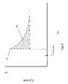
- FIG. 2shows a theoretical plot of current as a function of time after application of a potential in an electrochemical test strip for detection of glucose in which the test strip has facing working and counter electrodes, and the spacing of the electrodes is such that the recycling of mediator between the electrodes occurs.
- FIG. 3shows a plot of the applied voltage, V app , and the potential difference between the electrode, V elect , as a function of time.
- FIG. 4shows a plot of current as a function of time when a potential is reapplied to the electrodes after t threshold is reached.
- FIG. 5shows a plot of voltage versus time, that illustrates the drop in voltage that occurs as result of electrode resistance.
- FIG. 6shows an exterior view of a meter.
- FIG. 7shows connection of a test strip and connectors in a meter
- FIG. 8shows a circuit diagram for switching between amperometric and potentiometric modes.
- FIG. 9shows a circuit diagram for switching between amperometric and potentiometric modes.
- FIG. 10shows the relationship between differential capacitance and potential.
- FIG. 11shows measured differential capacitance for filled and partially filled strips.
- FIG. 12shows lot-to-lot variation of differential capacitance as a function of time to 50 mV.
- FIGS. 13A and Boutline techniques for determining double-layer capacitance in accordance with the invention.
- glucoserefers to a material of interest that may be present in a sample.
- the examplesuse glucose as an analyte, but the present invention is independent of both the type and amount of analyte. Accordingly, application to glucose detection systems should be viewed as merely a specific and non-limiting embodiment.
- (b) “determination of an analyte”refers to qualitative, semi-quantitative and quantitative processes for evaluating a sample. In a qualitative evaluation, a result indicates whether or not analyte was detected in the sample. In a semi-quantitative evaluation, the result indicates whether or not analyte is present above some pre-defined threshold. In a quantitative evaluation, the result is a numerical indication of the amount of analyte present.
- double layerrefers to the charged layers which form at a conductor/electrolyte interface as a result of adsorption of ions on the conductor surface causing a localized layer of neutralizing mirror charges in the conductor to form near the solid surface.
- the double layeris formed at each electrode in an electrochemical test strip when a liquid sample is present in contact with the electrode, whether or not a potential is applied. The amount of charge in a double layer, however, is a function of the electrode potential.
- the double layer structurebehaves essentially as a capacitor.
- the measured double layer capacitanceis dominated by one electrode, for example, if one electrode has a substantially larger area, or where the adsorpoion of ions of one charge is stronger than ions of the other charge in the sample.
- the positive electrodeis frequently dominant because of the greater ease with which negative ions, for example chloride ions, lose their hydration shell and are incorporated into the double layer.
- Double layer capacitance measured in these instancesis within the scope of the invention, although care should be taken where one electrode is dominant that the geometry of filling is such that the double layer capacitance of the dominant electrode is representative of the fill-state of the electrochemical strip.
- double layer chargingis the process of increasing the charge stored in a double layer as a result of an applied potential.
- double layer charging at the electrodesrefer to charging at both electrodes or at a dominant electrode.
- double layer dischargingis the process of decreasing the charge stored in a double layer as a result of switching off an applied potential.
- double layer discharging at the electrodesrefer to discharging at both electrodes or at a dominant electrode.
- electrochemical test striprefers to a strip having at least two electrodes, and any necessary reagents for determination of an analyte in a sample placed between the electrodes.
- the electrochemical test stripis disposable after a single use, and has connectors for attachment to a separate and reusable meter that contains the electronics for applying potential, analyzing signals and displaying a result.
- facing electrodesare a pair of electrodes disposed parallel to but in a separate plane from each other. Some or all of the opposed surfaces of a pair of facing electrodes overlap, such that potential gradients and current flows between the electrodes are in a direction substantially perpendicular to the opposed surfaces. Facing electrodes are distinguished from side-by-side electrodes in which the two electrode surfaces lie in the same plane, and in which potential gradients and current flow is substantially parallel to the surface of the electrodes.
- the present inventioncan be used with either facing or side-by-side electrodes, as well as other geometric arrangements.
- switching offrefers to the creation of an open circuit that forces the current to be zero (by opening a switch or introducing a high impedance into the circuit) that allows a built-up chemical concentration gradient and ion adsorption in the double layer to determine the potential between the electrodes. This is not the same thing as setting the voltage to zero volts.
- Electrode resistancecauses a difference between the applied voltage, and the actual voltage perceived by the electrochemistry at the electrode. Electrode resistance arises as a result of the resistance of the electrode material and the connectors associated with the electrodes, fouling of the electrode and similar factors.
- V dropis the difference between the applied voltage and the actual voltage that arises as a result of electrode resistance.
- oxygen carrying capacityrefers to the capacity of the sample to hold oxygen, in dissolved form and in a red blood cell reservoir.
- t mobis a time determined experimentally during an analysis that reflects the mobility of mediator in a particular sample in a particular test cell. t mob is the time after the applied potential is switched off, that it takes for the potential between the electrodes to decay to a pre-determined value.
- predeterminedis used in this application to refer to amounts or values that are determined empirically for a particular meter or test strip or meter/strip combination. The predetermined amounts or values will reflect an optimization for the needs of the user, taking into account the confidence levels needed, and need not achieve the best possible results or 100% accuracy.
- Electrochemical detection of an analyte such as glucoseis conventionally achieved by applying a potential to an electrochemical cell containing a sample to be evaluated for the presence/amount of glucose, an enzyme that oxidizes glucose, such as glucose oxidase, and a redox mediator.
- an enzyme that oxidizes glucosesuch as glucose oxidase
- a redox mediatorAs shown in FIG. 1 , the enzyme oxidizes glucose to form gluconolactone and a reduced form of the enzyme.
- Oxidized mediatorreacts with the reduced enzyme to regenerate the active oxidase and produced a reduced mediator.
- Reduced mediatoris oxidized at one of the electrodes, and electrochemical balance is maintained by a reducing reaction at the other electrode to result in a measurable current.
- the measured currentis related to the amount of glucose in the sample, and various techniques are known for determining glucose concentrations in such a system. (See, for example, U.S. Pat. Nos. 6,284,125; 5,942,102; 5,352,2,351; and 5,243,516, which are incorporated herein by reference.)
- FIG. 2shows a theoretical plot of current, as a function of time after application of a potential in an electrochemical test strip for detection of glucose in which the test strip has facing working and counter electrodes, and the spacing of the electrodes is close together, such that recycling of mediator/charge carriers between the electrodes occurs, i.e., such that a shuttle current resulting from the oxidation and reduction of the mediator at the electrodes, independent of the presence of remaining analyte can be observed.
- the current traceshows an immediate initial current 21 on the time scale shown following application of the potential. This current is associated with the initial charging of the double layer and consumption of extraneous redox active species.
- the currentdecreases, because current is dependent on the mediator dissolving and then diffusing from the working electrode, where the reagents are deposited at the time of manufacture, to the counter electrode.
- the duration of this low current(indicated by arrow 20 ) is dependent on the rate at which the mediator dissolves, the distance between the electrodes and the effective distance that the mediator must travel to reach the counter electrode, and on the mobility of the mediator.
- Mediator mobilityis a property of the mediator itself, i.e., the diffusion coefficient, but is also dependent on other sample properties such as hematocrit and viscosity.
- measurement of glucose or other analytecan be done during the initial voltage application, or based on a signal measured after the second application of voltage.
- Determination of glucose or other analytes in a samplecan also be made using other electrochemical techniques. These include potentiometry, for example as described in U.S. Pat. No. 6,251,260, which is incorporated herein by reference, or coulometry, for example as described in U.S. Pat. No. 6,299,757 which is incorporated herein by reference.
- the present inventionuses a determination of double layer capacitance to assess the sufficiency of sample volume introduced into an electrochemical test strip. Determination of double layer capacitance requires a knowledge of the current and the change in voltage as a function of time which can be obtained during either the charging or discharging of the double layer. Furthermore, the change in voltage can be viewed as a large, single-step change in voltage in which case an integral capacitance is obtained; or as a instantaneous change in voltage as a function of time, in which case a differential capacitance is obtained.
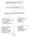
- double layer capacitancecan be determined using any of three approaches which are summarized in FIGS. 13A and B.
- FIG. 13Asummarizes determination of capacitance from discharge charge
- FIG. 13Bsummarizes determination of capacitance from charging charge.
- the I in this formulais the current just before t switch , that is at a time before the voltage is switched off that is sufficiently close to t switch that the observed current is representative of the current in the instant prior to the voltage switch off.
- the actual time difference between the measurement and t switchcan be on the order of 10 to 500 milliseconds, particularly if t switch falls in the plateau region where current is changing only slowly if at all.
- ⁇ Vis the drop in voltage between the initial V elect which in a simple model may be assumed to be equal to the difference between V app and the threshold voltage V threshold .
- ⁇ tis the difference between t threshold and t switch .
- the capacitance determined in this wayis related to the surface area of the electrodes or of the dominant electrode that is wetted by liquid sample such that a double layer can form.
- I thresholdthe value that I would have had at t threshold if the applied voltage had been maintained, can be estimated using a linear model, a fit to a decay model such as the Cottrell equation, or some other extrapolation from the observed behavior prior to t switch .
- a value of I that is half way between I switch and I threshold , or a mathematical integration of a decay modelcan then be suitably used in the determination of C int .
- V thresholdis determined based on the value of V app as well as an expected time course for the decay. If V threshold represents a large portion of V app , then the difference being measured is small, and the error is large. Further, as discussed below, in cases with resistive electrodes such as carbon electrodes there is an initial voltage drop, V drop , associated with the electrode resistance, and V threshold must be lower than V app ⁇ V drop . On the other hand, if V threshold is too low, then the time to take the measurement is longer, which is generally less acceptable from a user perspective.
- V thresholdis suitably at least 30 mV below V app and no lower than 60 mV, preferably no lower than 120 mV, and more preferably at least 150 mV.
- V appis 300 mV and V threshold is selected as a voltage value between 150-240 mV.
- differential capacitancecan be determined from the discharge cycle.
- the applied potentialis switched off at time t switch .
- an instantaneous measurement of the slope of the voltage decayis determined.
- the time at which the measurement is madecan be at a predetermined interval after t switch based on standard performance of a given strip design, for example between 1 and 500 msec after t swtich , or it may be determined based on the performance of the strip as it is used, in a manner comparable to taking a time measurement at V threshold as described above.
- the value for I in this equationmay be the value of the current just before t switch as described above, or it may be the projected value for the current at the measurement time, using any of the models described above.
- FIG. 4shows a plot of current as a function of time, when a potential is reapplied to the electrodes after t threshold is reached. Following reapplication of the potential, there is a second current spike 41 followed by a decay to a current value that is essentially equal to the projected current from before the applied potential is turned off.
- the shaded area 42 under the current curvecan be determined by integration of the signal, or a representative portion thereof, or using a triangular approximation, and is indicative of the charging of the double layer. Theoretically, the discharge charge measured as described above in A and this charging charge should be equal. In practice, experimental differences are observed, but the charging charge can nonetheless be used separately, or as a confirmation of the discharge charge as an assessment of partial fill.
- the voltage reappliedis the same as the voltage that is initially applied.
- the reapplied voltagemay also be greater or smaller than the initially applied voltage, provided it restablishes the same diffusion limiting condition.
- the time interval over which the current measurements are mademay be established statically, that is fixed based on strip design, or dynamically. In the case of a static definition of measurement time, it is desirable to start measuring the current at a time after the current spike, for example 1 to 10 msec after, to eliminate effects of circuit response/saturation. The ending time for the measurement is then a predefined prior of time later, for example 100-1000 msec.
- the end timemay also be set as a multiple, for example an integer multiple, of ⁇ t from the discharge phase.
- the measurement intervalmay be equal to ⁇ t, or ⁇ dt.
- the measurement time intervalis determined based on characteristics of the measured current.
- measurementcan be made until a predetermined drop in the excess current (I obs ⁇ I switch ) is achieved, for example more than 50%, preferably at least 75% and more preferably at least 90%, where I obs , is the current observed at any given time after t switch .
- Measurementcan also continue until current has decreased to a level approaching I switch , for example 1.1 ⁇ I switch .
- V dropis a function of several factors, including the resistance of the electrode material and the connectors associated with the electrodes, fouling of the electrode and similar factors.
- the dropis larger with carbon electrodes than with a low resistance electrode such as one made of gold.
- the magnitude of V dropis taken into account in any of several ways.
- V thresholdsuitably depends on V drop .
- ⁇ V( V app ⁇ V drop ) ⁇ V threshold .
- the voltage at which the measurement is takencan be described as ((V app ⁇ V drop ) minus a predetermined amount).
- the value of double layer capacitanceis corrected for the temperature of the sample, provided that the meter or the test strip is provided with means for determining this temperature.
- C DLis the double layer capacitance as determined by any of the techniques outlined above.
- T-correctionhas the same form as described in commonly assigned U.S. patent application Ser. No. 10/907,803, filed Apr. 15, 2005, which is incorporated herein by reference, although in that application the correction term is used to correct the analyte concentration measurement.
- the temperature correction termcan be assessed by any technique that gives a measure of oxygen carrying capacity, in combination with a temperature measurement for the sample.
- the present inventorshave found that a graph of measured raw analyte concentration versus a measure of oxygen carrying capacity is a line with a slope that is dependent on the temperature at which the measurements are made, but that is independent of pO 2 and glucose concentration over normal ranges of values. Changes in pO 2 or glucose concentration result in an additive offset of the graphed lines, but not a change in slope.
- OCCis a measure of oxygen carrying capacity such as hematocrit
- the constantis an empirically determined factor with a positive or negative sign.
- the temperature correction factorcan be improved when there is a large body of data gathered at one temperature and a limited body of data gathered at the measurement temperature by determining only the slope from the data gathered at the measurement temperature and determining the intercept from all of the available data.
- the parameter Imay be a constant established for the strip and meter combination, and only the slope need to be determined experimentally.
- t moba measure of the mobility of the mediator is used as the measure of oxygen carrying capacity.
- t mobis determined during the decay of the potential gradient following switching off of the potential. The decay in potential is monitored until the observed potential has decreased to a pre-determined value, V mob . Decreases to around 50 mV are convenient where the applied voltage is on the order of 300 mV, although somewhat smaller values such as 47 mV or 48 mV may be found to provide optimum results in particular experimental configurations.
- V mobis suitably 0.025 to 0.1V
- V mobis suitably in the range of 25 to 100 mV, preferably 45 to 50 mV.
- t mobis the time is takes after t switch for this voltage to be reached.
- determining a measure of the rate of decaymay also be employed. For example, an instantaneous slope of the decay of the potential can be determined, or the decrease in voltage over a predetermined time can be used.
- the metermay also select a particular time window and perform a linear regression on V versus log(t) or In(t) to find t mob which is the time to a particular voltage. If the V mob does not fall within the selected window, a projection based on this linear fit can be used.
- the specific methodologyis not critical, provided that the value of the measured decay is taken into account in determining the correction function.
- the hematocrit measurementis used in a multiplicative correction, as opposed to the additive correction of the present invention.
- the measurementcan be used in both modes, however, just as t mob is used for both types of corrections as described above. This is because hematocrit is a measure of the red blood cells, and red blood cells have an oxygen carrying capacity.
- hematocrit measurementis a measure of oxygen carrying capacity in present invention.
- a series of calibration measurementsare taken to obtain data point pairs of uncorrected analyte concentration and hematocrit at each of a plurality of temperatures.
- the data pointsare fit to a linear model and the slope of the line is determined.
- this slopeis independent of glucose and pO 2 such that while these parameters need to be kept the same across experiments, the particular values are not significant.
- the resulting slope/temperature data point pairsare then fitted to a linear model, to determine the slope and intercept which is incorporated into an additive correction factor as described above.
- the linear modelmay be sufficient only for a narrow range of the data.
- An improved additive correction factormay be determined for a wider range of temperatures or oxygen carrying capacities by introducing non-linear terms such as quadratic equations of exponents to terms.
- the meterfirst acts in an amperometric mode, and then after the applied potential is switched off, in a potentiometric mode.
- a potentiometric modeIn order to enhance the quality and consistency of measurements made when operating in potentiometric mode, if is desirable to perform the switch to potentiometric mode only after a stable diffusion gradient of oxidized and reduced mediator has formed within the electrochemical test cell. In general, the potentiometry measurements will give the same stable reading at any point after the concentration gradients have formed a stable profile that extends “far enough” into the bulk of the sample.
- t switchcan be determined dynamically.
- t switchis determined dynamically from the determined value of t peak (the time of peak 22 , in FIG. 2 ) by adding a time interval, for example 2 to 3 seconds to the determined value of t peak .
- t switchis determined dynamically using a fixed value of t switch when t peak is small and t peak plus a predetermined amount when t peak is larger.
- t switchmay have a fixed value of 3.5 second when t peak is less than 1.5 seconds, and be equal to t peak plus an offset (for example 2 second) when t peak is greater than 1.5 seconds.
- a third mode for measurementis established for circumstances when t peak occurs at times that are longer than ordinary.
- t peakoccurs above a predetermined threshold, for example 5 seconds
- t switchis suitably determined as a function of t peak and an additive correction factor that uses predetermined constants derived from the slope of the Cottrell current.
- the method of the inventioncan be used with any strip that has facing electrodes, providing that a meter apparatus is provided that can receive the strip and provide the necessary applications of voltage and signal processing.
- a meteralso forms an aspect of the present invention.
- the inventionprovides a meter for receiving an electrochemical test strip having electrodes and providing a determination of an analyte in a sample applied to the electrochemical test strip when received in the meter, said meter comprising
- FIG. 6shows an external view of a meter in accordance with the invention.
- the meterhas a housing 61 , and a display 62 .
- the housing 61has a slot 63 , into which a test strip is inserted for use.
- the metermay also have a button 64 for signaling the start of the measurement cycle, or may have an internal mechanism for detecting the insertion of a test strip or the application of a sample.
- Such mechanismsare known in the art, for example from U.S. Pat. Nos. 5,266,179; 5,320,732; 5,438,271 and 6,616,819, which are incorporated herein by reference.
- buttons, displayssuch as LCD displays, RF, infrared or other wireless transmitters, wire connectors such as USB, parallel or serial connections constitute means for receiving input from and communicating a result to a user, and can be used individually and in various combinations.
- FIG. 7shows an interior view in which the connection of the meter to a test strip is shown.
- the test strip 71has contacts 72 , 73 by which the electrodes are placed in electrical contact with contacts 74 , 75 of the meter.
- the means for making a DC determination of double layer capacitancecomprises circuits, such as on a circuit board associated with a programmed microprocessor that interacts with the circuits to provide the desired switching between amperometric and potentiometric modes and to monitor curreent and voltage as described.
- circuitssuch as on a circuit board associated with a programmed microprocessor that interacts with the circuits to provide the desired switching between amperometric and potentiometric modes and to monitor curreent and voltage as described.
- Apparatus suitable for switching between an amperometric mode of operation in which current is measured and a potentiometric mode of operation in which a potential difference between the electrodes is measuredare described in U.S. Provisional Applications No. 60/521,592, filed May 30, 2004, and 60/594,285 filed Mar. 25, 3005 which are incorporated herein by reference.
- FIG. 8shows an electrical schematic of one embodiment of the meter of the invention.
- Working electrode 80is connected to op amp 81 via a connector containing switch 82 , and to op amp 83 .
- Counter electrode 84is connected to op amps 85 and 86 .
- Op amps 83 , 85 and 86are high impedance input amplifiers. When operating in amperometric mode to determine an analyte, a voltage V 2 is applied to op amp 81 , and a voltage V 1 is applied to op amp 85 , V 2 being greater than V 1 .
- the resulting potential difference between the electrodesresults in the generation of a current that is related to the amount of analyte, and this current can be monitored at output 87 and converted to an indication of the presence or amount of analyte.
- switch 82is opened to create an open circuit and stop application of the potential difference, current flow ceases, and the output of amplifier 86 assumes the potential of the counter electrode, while the output of amplifier 83 assumes the potential of the working electrode 80 .
- the difference between the output from op amp 83 and op amp 86indicates the decay in chemical potential and is processed in accordance with the methods described above to create an indication of partial fill.
- FIG. 9shows an alternative version of this circuit using only two op amps and an increased number of switches.
- Working electrode 80is connected to op amp 81 which received input voltage V 2 .
- Counter electrode 84is connected to high input impedance op amp 90 via one of two switched paths.
- Input voltage V 1is connected to the circuit via a third switched path.
- switch 91 and 93are closed, and switch 92 is open, the circuit functions in amperometric mode, and the output at 95 reflects current flow at the electrodes.
- switch 92is closed, and switches 91 and 93 are open, the circuit operates in potentiometric mode and the output at 95 assumes the potential of the counter electrode (similar to amplifier 86 in FIG. 8 ).
- the output at 95indirectly reflects the difference in potential between the electrodes.
- the actual difference in potential between the electrodesis the difference between the output at 95 , and the output of op amp 81 (at 80 , the working electrode).
- a signal to the user indicating incomplete fillis suitably generated when the measured value of the double layer capacitance is below the pre-determined level.
- the measured values of double-layer capacitance as described abovealso provides an indication of the quality of electrodes made using processes such as screen printing. Where the printing is of poor or inconsistent quality, the variation among the observed double-layer capacitance is larger than for a lot in which the printing quality is consistently good. (See FIG. 12 and Example 4).
- a further aspect of the inventionprovides a method for quality inspection of a lot of electrochemical test strips, comprising the steps of:
- test stripsneed to be a sufficient number to be representative of the lot as a whole, yet not so great as to result in destructive testing on an economically significant portion of the lot. Further, it is desirable to take test strips for this testing from different times within the preparation of the lot, and if multiple-strip sheets are made and then cut apart from different parts of the sheets.
- the sample applied to the test stripscould be a blood sample.
- a control solution containing a charge carrierfor example a mixture of ferrocyanide and ferricyanide.
- the “variability” of the measured double layer capacitancecan be determined using any acceptable mathematical analysis. For example, variability can be indicated by the range of measured values, or the standard deviation of the measured values.
- the differential capacitance for a given sample/test stripvaries significantly with the potential at which it is measured. Further, the graph shows a region 100 in which the change in C dif with voltage is less, and it is in this region of voltage difference in which measurements for determination of C dif are preferably made.
- 300 mVwas applied to electrochemical test strips with blood samples having either 2.79 mM or 20.2 mM glucose until a plateau current was observed. The applied voltage was then switched off, and the charge passed in discharging the double layer from 250 mV to 150 mV was measured. 300 mV was then reapplied, and the charge passed to recharge the double layer to 250 mV was observed.
- the relationship between the charging and discharging currentwas observed to be substantially linear with a zero intercept. However, the charge determined for recharging was lower than that for discharging, indicating that the measurement time of 100 ms was not sufficient for the recharging double layer to fully equilibrate with the solution. The observed amounts of charge were independent of glucose concentration, although the higher concentration decayed markedly faster.
- FIG. 11shows the measured differential capacitance for a variety of strips.
- the horizontal line in FIG. 11is a threshold level of differential capacitance set at 1.7 ⁇ F that could be used with this test strip in assessing sample sufficiency. As shown, all of the filled samples resulted in a capacitance above this threshold, while only three of the partial fills would have given a false acceptance.
- FIG. 12shows results for the ten lots, plotting differential capacitance versus time for a decay to 50 mV. Two things are observable from this graph. First, for 8 of the ten lots, differential capacitance is fairly constant, although the time to reach the 50 mV drop is variable. This argues in favor of dynamically determining the time of measurement, but exhibits the general robustness of the technique. The two lots that deviated from the other 8 also display a fairly constant level of capacitance, and very little variation in time to 50 mV. It was determined that in these lots the carbon electrodes were screen printed using a different technique. Thus, the cut off established for capacitance to account for partial fill can account for lot-to-lot variation with a consistent manufacturing technique, but may need to be reset where changes in manufacturing techniques are changed.
Landscapes
- Health & Medical Sciences (AREA)
- Life Sciences & Earth Sciences (AREA)
- Chemical & Material Sciences (AREA)
- Physics & Mathematics (AREA)
- Pathology (AREA)
- Molecular Biology (AREA)
- Engineering & Computer Science (AREA)
- Analytical Chemistry (AREA)
- Biochemistry (AREA)
- General Health & Medical Sciences (AREA)
- General Physics & Mathematics (AREA)
- Immunology (AREA)
- Electrochemistry (AREA)
- Chemical Kinetics & Catalysis (AREA)
- Biomedical Technology (AREA)
- Biophysics (AREA)
- Hematology (AREA)
- Urology & Nephrology (AREA)
- Food Science & Technology (AREA)
- Medicinal Chemistry (AREA)
- Investigating Or Analyzing Materials By The Use Of Electric Means (AREA)
- Investigating Or Analysing Biological Materials (AREA)
Abstract
Description
- (a) introducing sample to an electrochemical test strip;
- (b) applying a potential difference between the electrodes of the test strip;
- (c) switching off the applied potential and optionally reapplying a second potential;
- (d) observing current generated and determining from the observed current a double layer charging or discharging between the electrodes;
- (e) observing a voltage change after the applied potential is switched off, and determining the double layer capacitance of test strip from the measured double layer charging or discharging and the observed voltage change; and
- (f) comparing the determined double layer capacitance to a reference value, wherein a double layer capacitance less than the reference value is an indication that the liquid sample covers a portion of the facing electrodes and that the electrochemical test strip is only partially filled.
- (1) (1) applying a potential between the electrodes,
- (2) (2) switching off the applied potential between the electrodes at a time tswitch;
- (3) (3) monitoring the decay in the potential difference between the electrodes to identify the time, tthreshold, required for the potential to decay to a threshold value; and
- (4) (4) determining the amount of double layer charge discharged during the interval tswitchto tthreshold.
- (1) (1) applying a first potential between the electrodes,
- (2) (2) switching off the applied potential between the electrodes at a time tswitch;
- (3) (3) monitoring the decay in the potential difference between the electrodes to identify the time, tthreshold, required for the potential to decay to a threshold value;
- (4) (4) applying a second potential between the electrodes at tthreshold, whereby a current spike is generated;
- (5) (5) determining the amount of double layer charging, as reflected by the area under the current spike; and
- (6) (6) determining the double layer capacitance from the amount of double layer charging and the current at time tswitch.
Cint=I/(ΔV/Δt).
Cdif=I/(dV/dt).
ΔV=(Vapp−Vdrop)−Vthreshold.
Ct-corr=CDL−T-correction
temperature correction term=constant×[(S×T)+I]×OCC
- (a) a housing having a slot for receiving an electrochemical test strip;
- (b) communications means for receiving input from and communicating a result to a user; and
- (c) means for making a DC determination of double layer capacitance on a test strip containing sample received within the meter, and comparing the determined double layer capacitance to a reference value, wherein a double layer capacitance less than the reference value is an indication that the liquid sample covers a portion of the electrodes and that the electrochemical test strip is only partially filled.
- (a) obtaining a plurality of test strips from the lot;
- (b) applying a sample to each of the test strips;
- (c) measuring the double-layer capacitance of the test strips in the presence of the sample; and
- (d) determining the variability in measured double-layer capacitance, wherein a variability in excess of a defined threshold indicates a quality deficiency in the test strips.
Claims (17)
Cint =IΔt /ΔV,
charge=Iswitch Δt
Cdif=I /(dV/dt),
Priority Applications (11)
| Application Number | Priority Date | Filing Date | Title |
|---|---|---|---|
| US10/907,813US7547382B2 (en) | 2005-04-15 | 2005-04-15 | Determination of partial fill in electrochemical strips |
| EP06727948.9AEP1869453B1 (en) | 2005-04-15 | 2006-04-15 | Determination of partial fill in electrochemical strips |
| JP2008506044AJP2008536139A (en) | 2005-04-15 | 2006-04-15 | Determination of partial filling in electrochemical specimens |
| ES06727948.9TES2546455T3 (en) | 2005-04-15 | 2006-04-15 | Determination of partial filling in electrochemical strips |
| CNA200680021625XACN101198868A (en) | 2005-04-15 | 2006-04-15 | Determination of partial filling of electrochemical strips |
| EP16175119.3AEP3104175B1 (en) | 2005-04-15 | 2006-04-15 | Determination of analyte that includes partial fill in electrochemical strips |
| EP15160465.9AEP2908130B1 (en) | 2005-04-15 | 2006-04-15 | Quality inspection of electrochemical test strips |
| AU2006233770AAU2006233770B2 (en) | 2005-04-15 | 2006-04-15 | Determination of partial fill in electrochemical strips |
| PCT/IB2006/051180WO2006109277A2 (en) | 2005-04-15 | 2006-04-15 | Determination of partial fill in electrochemical strips |
| CA2604374ACA2604374C (en) | 2005-04-15 | 2006-04-15 | Determination of partial fill in electrochemical strips |
| KR1020077026520AKR101289757B1 (en) | 2005-04-15 | 2006-04-15 | Determination of partial fill in electrochemical strips |
Applications Claiming Priority (1)
| Application Number | Priority Date | Filing Date | Title |
|---|---|---|---|
| US10/907,813US7547382B2 (en) | 2005-04-15 | 2005-04-15 | Determination of partial fill in electrochemical strips |
Publications (2)
| Publication Number | Publication Date |
|---|---|
| US20060231418A1 US20060231418A1 (en) | 2006-10-19 |
| US7547382B2true US7547382B2 (en) | 2009-06-16 |
Family
ID=37087419
Family Applications (1)
| Application Number | Title | Priority Date | Filing Date |
|---|---|---|---|
| US10/907,813Active2028-01-18US7547382B2 (en) | 2005-04-15 | 2005-04-15 | Determination of partial fill in electrochemical strips |
Country Status (9)
| Country | Link |
|---|---|
| US (1) | US7547382B2 (en) |
| EP (3) | EP1869453B1 (en) |
| JP (1) | JP2008536139A (en) |
| KR (1) | KR101289757B1 (en) |
| CN (1) | CN101198868A (en) |
| AU (1) | AU2006233770B2 (en) |
| CA (1) | CA2604374C (en) |
| ES (1) | ES2546455T3 (en) |
| WO (1) | WO2006109277A2 (en) |
Cited By (13)
| Publication number | Priority date | Publication date | Assignee | Title |
|---|---|---|---|---|
| WO2012037486A1 (en) | 2010-09-17 | 2012-03-22 | Agamatrix, Inc. | Method and apparatus for encoding test strips |
| WO2014143495A1 (en) | 2013-03-15 | 2014-09-18 | Agamatrix, Inc. | Analyte detection meter and associated method of use |
| US8936713B2 (en) | 2009-12-11 | 2015-01-20 | Lifescan Scotland Limited | Fill sufficiency method and system |
| US9213015B2 (en) | 2011-02-23 | 2015-12-15 | Panasonic Healthcare Holdings Co., Ltd. | Biological sample measuring device |
| US9451908B2 (en) | 2006-10-04 | 2016-09-27 | Dexcom, Inc. | Analyte sensor |
| US9649069B2 (en) | 2003-08-22 | 2017-05-16 | Dexcom, Inc. | Systems and methods for replacing signal artifacts in a glucose sensor data stream |
| US9750441B2 (en) | 2003-12-09 | 2017-09-05 | Dexcom, Inc. | Signal processing for continuous analyte sensor |
| US10180420B2 (en)* | 2013-06-10 | 2019-01-15 | Roche Diagnostics Operations, Inc. | Methods for detecting an analyte and performing a failsafe step in a body fluid using optical and impedance measurements |
| US10980461B2 (en) | 2008-11-07 | 2021-04-20 | Dexcom, Inc. | Advanced analyte sensor calibration and error detection |
| US11000215B1 (en) | 2003-12-05 | 2021-05-11 | Dexcom, Inc. | Analyte sensor |
| US11382539B2 (en) | 2006-10-04 | 2022-07-12 | Dexcom, Inc. | Analyte sensor |
| US11432772B2 (en) | 2006-08-02 | 2022-09-06 | Dexcom, Inc. | Systems and methods for replacing signal artifacts in a glucose sensor data stream |
| US11559260B2 (en) | 2003-08-22 | 2023-01-24 | Dexcom, Inc. | Systems and methods for processing analyte sensor data |
Families Citing this family (95)
| Publication number | Priority date | Publication date | Assignee | Title |
|---|---|---|---|---|
| US6036924A (en) | 1997-12-04 | 2000-03-14 | Hewlett-Packard Company | Cassette of lancet cartridges for sampling blood |
| US6391005B1 (en) | 1998-03-30 | 2002-05-21 | Agilent Technologies, Inc. | Apparatus and method for penetration with shaft having a sensor for sensing penetration depth |
| DE10057832C1 (en) | 2000-11-21 | 2002-02-21 | Hartmann Paul Ag | Blood analysis device has syringe mounted in casing, annular mounting carrying needles mounted behind test strip and being swiveled so that needle can be pushed through strip and aperture in casing to take blood sample |
| US8641644B2 (en) | 2000-11-21 | 2014-02-04 | Sanofi-Aventis Deutschland Gmbh | Blood testing apparatus having a rotatable cartridge with multiple lancing elements and testing means |
| US9795747B2 (en) | 2010-06-02 | 2017-10-24 | Sanofi-Aventis Deutschland Gmbh | Methods and apparatus for lancet actuation |
| US7041068B2 (en) | 2001-06-12 | 2006-05-09 | Pelikan Technologies, Inc. | Sampling module device and method |
| US9427532B2 (en) | 2001-06-12 | 2016-08-30 | Sanofi-Aventis Deutschland Gmbh | Tissue penetration device |
| US7749174B2 (en) | 2001-06-12 | 2010-07-06 | Pelikan Technologies, Inc. | Method and apparatus for lancet launching device intergrated onto a blood-sampling cartridge |
| WO2002101359A2 (en) | 2001-06-12 | 2002-12-19 | Pelikan Technologies, Inc. | Integrated blood sampling analysis system with multi-use sampling module |
| JP4272051B2 (en) | 2001-06-12 | 2009-06-03 | ペリカン テクノロジーズ インコーポレイテッド | Blood sampling apparatus and method |
| US9226699B2 (en) | 2002-04-19 | 2016-01-05 | Sanofi-Aventis Deutschland Gmbh | Body fluid sampling module with a continuous compression tissue interface surface |
| AU2002344825A1 (en) | 2001-06-12 | 2002-12-23 | Pelikan Technologies, Inc. | Method and apparatus for improving success rate of blood yield from a fingerstick |
| US7344507B2 (en) | 2002-04-19 | 2008-03-18 | Pelikan Technologies, Inc. | Method and apparatus for lancet actuation |
| US7981056B2 (en) | 2002-04-19 | 2011-07-19 | Pelikan Technologies, Inc. | Methods and apparatus for lancet actuation |
| US8337419B2 (en) | 2002-04-19 | 2012-12-25 | Sanofi-Aventis Deutschland Gmbh | Tissue penetration device |
| EP1395185B1 (en) | 2001-06-12 | 2010-10-27 | Pelikan Technologies Inc. | Electric lancet actuator |
| JP4209767B2 (en) | 2001-06-12 | 2009-01-14 | ペリカン テクノロジーズ インコーポレイテッド | Self-optimized cutting instrument with adaptive means for temporary changes in skin properties |
| US7344894B2 (en) | 2001-10-16 | 2008-03-18 | Agilent Technologies, Inc. | Thermal regulation of fluidic samples within a diagnostic cartridge |
| US7524293B2 (en) | 2002-04-19 | 2009-04-28 | Pelikan Technologies, Inc. | Method and apparatus for penetrating tissue |
| US9314194B2 (en) | 2002-04-19 | 2016-04-19 | Sanofi-Aventis Deutschland Gmbh | Tissue penetration device |
| US7674232B2 (en) | 2002-04-19 | 2010-03-09 | Pelikan Technologies, Inc. | Method and apparatus for penetrating tissue |
| US7141058B2 (en) | 2002-04-19 | 2006-11-28 | Pelikan Technologies, Inc. | Method and apparatus for a body fluid sampling device using illumination |
| US8267870B2 (en) | 2002-04-19 | 2012-09-18 | Sanofi-Aventis Deutschland Gmbh | Method and apparatus for body fluid sampling with hybrid actuation |
| US7582099B2 (en) | 2002-04-19 | 2009-09-01 | Pelikan Technologies, Inc | Method and apparatus for penetrating tissue |
| US7892183B2 (en) | 2002-04-19 | 2011-02-22 | Pelikan Technologies, Inc. | Method and apparatus for body fluid sampling and analyte sensing |
| US7374544B2 (en) | 2002-04-19 | 2008-05-20 | Pelikan Technologies, Inc. | Method and apparatus for penetrating tissue |
| US7371247B2 (en) | 2002-04-19 | 2008-05-13 | Pelikan Technologies, Inc | Method and apparatus for penetrating tissue |
| US7547287B2 (en) | 2002-04-19 | 2009-06-16 | Pelikan Technologies, Inc. | Method and apparatus for penetrating tissue |
| US7563232B2 (en) | 2002-04-19 | 2009-07-21 | Pelikan Technologies, Inc. | Method and apparatus for penetrating tissue |
| US9248267B2 (en) | 2002-04-19 | 2016-02-02 | Sanofi-Aventis Deustchland Gmbh | Tissue penetration device |
| US7648468B2 (en) | 2002-04-19 | 2010-01-19 | Pelikon Technologies, Inc. | Method and apparatus for penetrating tissue |
| US9795334B2 (en) | 2002-04-19 | 2017-10-24 | Sanofi-Aventis Deutschland Gmbh | Method and apparatus for penetrating tissue |
| US8579831B2 (en) | 2002-04-19 | 2013-11-12 | Sanofi-Aventis Deutschland Gmbh | Method and apparatus for penetrating tissue |
| US8784335B2 (en) | 2002-04-19 | 2014-07-22 | Sanofi-Aventis Deutschland Gmbh | Body fluid sampling device with a capacitive sensor |
| US7331931B2 (en) | 2002-04-19 | 2008-02-19 | Pelikan Technologies, Inc. | Method and apparatus for penetrating tissue |
| US7229458B2 (en) | 2002-04-19 | 2007-06-12 | Pelikan Technologies, Inc. | Method and apparatus for penetrating tissue |
| US7491178B2 (en) | 2002-04-19 | 2009-02-17 | Pelikan Technologies, Inc. | Method and apparatus for penetrating tissue |
| US7297122B2 (en) | 2002-04-19 | 2007-11-20 | Pelikan Technologies, Inc. | Method and apparatus for penetrating tissue |
| US8221334B2 (en) | 2002-04-19 | 2012-07-17 | Sanofi-Aventis Deutschland Gmbh | Method and apparatus for penetrating tissue |
| US7481776B2 (en) | 2002-04-19 | 2009-01-27 | Pelikan Technologies, Inc. | Method and apparatus for penetrating tissue |
| US7976476B2 (en) | 2002-04-19 | 2011-07-12 | Pelikan Technologies, Inc. | Device and method for variable speed lancet |
| US7717863B2 (en) | 2002-04-19 | 2010-05-18 | Pelikan Technologies, Inc. | Method and apparatus for penetrating tissue |
| US7410468B2 (en) | 2002-04-19 | 2008-08-12 | Pelikan Technologies, Inc. | Method and apparatus for penetrating tissue |
| US7901362B2 (en) | 2002-04-19 | 2011-03-08 | Pelikan Technologies, Inc. | Method and apparatus for penetrating tissue |
| US7232451B2 (en) | 2002-04-19 | 2007-06-19 | Pelikan Technologies, Inc. | Method and apparatus for penetrating tissue |
| US7708701B2 (en) | 2002-04-19 | 2010-05-04 | Pelikan Technologies, Inc. | Method and apparatus for a multi-use body fluid sampling device |
| US7909778B2 (en) | 2002-04-19 | 2011-03-22 | Pelikan Technologies, Inc. | Method and apparatus for penetrating tissue |
| US8702624B2 (en) | 2006-09-29 | 2014-04-22 | Sanofi-Aventis Deutschland Gmbh | Analyte measurement device with a single shot actuator |
| US7291117B2 (en) | 2002-04-19 | 2007-11-06 | Pelikan Technologies, Inc. | Method and apparatus for penetrating tissue |
| US8574895B2 (en) | 2002-12-30 | 2013-11-05 | Sanofi-Aventis Deutschland Gmbh | Method and apparatus using optical techniques to measure analyte levels |
| US7850621B2 (en) | 2003-06-06 | 2010-12-14 | Pelikan Technologies, Inc. | Method and apparatus for body fluid sampling and analyte sensing |
| WO2006001797A1 (en) | 2004-06-14 | 2006-01-05 | Pelikan Technologies, Inc. | Low pain penetrating |
| EP1635700B1 (en) | 2003-06-13 | 2016-03-09 | Sanofi-Aventis Deutschland GmbH | Apparatus for a point of care device |
| US8282576B2 (en) | 2003-09-29 | 2012-10-09 | Sanofi-Aventis Deutschland Gmbh | Method and apparatus for an improved sample capture device |
| EP1680014A4 (en) | 2003-10-14 | 2009-01-21 | Pelikan Technologies Inc | METHOD AND DEVICE FOR A VARIABLE USER INTERFACE |
| US7822454B1 (en) | 2005-01-03 | 2010-10-26 | Pelikan Technologies, Inc. | Fluid sampling device with improved analyte detecting member configuration |
| US8668656B2 (en) | 2003-12-31 | 2014-03-11 | Sanofi-Aventis Deutschland Gmbh | Method and apparatus for improving fluidic flow and sample capture |
| WO2006011062A2 (en) | 2004-05-20 | 2006-02-02 | Albatros Technologies Gmbh & Co. Kg | Printable hydrogel for biosensors |
| JP5215661B2 (en) | 2004-05-21 | 2013-06-19 | アガマトリックス インコーポレーテッド | Electrochemical cell and method for making an electrochemical cell |
| WO2005120365A1 (en) | 2004-06-03 | 2005-12-22 | Pelikan Technologies, Inc. | Method and apparatus for a fluid sampling device |
| US8652831B2 (en) | 2004-12-30 | 2014-02-18 | Sanofi-Aventis Deutschland Gmbh | Method and apparatus for analyte measurement test time |
| US20070152683A1 (en)* | 2005-12-30 | 2007-07-05 | Karl Werner | Electronic device for analysis of a body fluid |
| US9149215B2 (en) | 2005-12-30 | 2015-10-06 | Roche Diabetes Care, Inc. | Portable analytical device |
| US8114269B2 (en)* | 2005-12-30 | 2012-02-14 | Medtronic Minimed, Inc. | System and method for determining the point of hydration and proper time to apply potential to a glucose sensor |
| US8529751B2 (en) | 2006-03-31 | 2013-09-10 | Lifescan, Inc. | Systems and methods for discriminating control solution from a physiological sample |
| WO2008049075A2 (en)* | 2006-10-18 | 2008-04-24 | Agamatrix, Inc. | Electrochemical determination of analytes |
| US8778168B2 (en) | 2007-09-28 | 2014-07-15 | Lifescan, Inc. | Systems and methods of discriminating control solution from a physiological sample |
| US8603768B2 (en) | 2008-01-17 | 2013-12-10 | Lifescan, Inc. | System and method for measuring an analyte in a sample |
| EP2265324B1 (en) | 2008-04-11 | 2015-01-28 | Sanofi-Aventis Deutschland GmbH | Integrated analyte measurement system |
| US8551320B2 (en) | 2008-06-09 | 2013-10-08 | Lifescan, Inc. | System and method for measuring an analyte in a sample |
| US9375169B2 (en) | 2009-01-30 | 2016-06-28 | Sanofi-Aventis Deutschland Gmbh | Cam drive for managing disposable penetrating member actions with a single motor and motor and control system |
| TWI388823B (en) | 2009-04-09 | 2013-03-11 | Bionime Corp | A method for estimating the distribution of a sample |
| CN101887047A (en)* | 2009-05-12 | 2010-11-17 | 华广生技股份有限公司 | Detection method for judging sample full condition |
| ES2886462T3 (en) | 2009-09-15 | 2021-12-20 | Agamatrix Inc | Implantable electrochemical biosensor system and method |
| US8101065B2 (en)* | 2009-12-30 | 2012-01-24 | Lifescan, Inc. | Systems, devices, and methods for improving accuracy of biosensors using fill time |
| WO2011104517A2 (en)* | 2010-02-25 | 2011-09-01 | Lifescan Scotland Limited | Capacitance detection in electrochemical assay |
| US20110208435A1 (en) | 2010-02-25 | 2011-08-25 | Lifescan Scotland Ltd. | Capacitance detection in electrochemical assays |
| US8965476B2 (en) | 2010-04-16 | 2015-02-24 | Sanofi-Aventis Deutschland Gmbh | Tissue penetration device |
| US8932445B2 (en)* | 2010-09-30 | 2015-01-13 | Cilag Gmbh International | Systems and methods for improved stability of electrochemical sensors |
| US9008744B2 (en)* | 2011-05-06 | 2015-04-14 | Medtronic Minimed, Inc. | Method and apparatus for continuous analyte monitoring |
| US20120306628A1 (en)* | 2011-05-31 | 2012-12-06 | Tara Chand Singhal | Integrated blood glucose measurement device with a test strip count system |
| TWI576583B (en)* | 2013-08-02 | 2017-04-01 | 達爾生技股份有限公司 | Determination methods for biochemical detection strips |
| TWI586333B (en)* | 2013-09-06 | 2017-06-11 | A blood volume detecting method and a detecting device using the same | |
| DE202014100630U1 (en) | 2014-02-13 | 2014-02-18 | Sanofi-Aventis Deutschland Gmbh | gauge |
| US10564123B2 (en) | 2014-05-25 | 2020-02-18 | United Arab Emirates University | Bioreactor system and method of operating same for cellular composition identification and quantification |
| US10436772B2 (en) | 2014-08-25 | 2019-10-08 | United Arab Emirates University | Method and system for counting white blood cells electrically |
| GB201413628D0 (en)* | 2014-07-31 | 2014-09-17 | Inside Biometrics Ltd | Method and device for determining volumetric sufficiency in an electrochemical test strip |
| US10907192B2 (en) | 2015-04-07 | 2021-02-02 | Polymer Technology Systems, Inc. | Systems and methods for artificial test strip controls |
| EP3427039B1 (en)* | 2016-03-11 | 2022-09-28 | Trividia Health, Inc. | Systems and methods for correction of on-strip coding |
| US10426389B2 (en) | 2016-04-28 | 2019-10-01 | Medtronic Minimed, Inc. | Methods, systems, and devices for electrode capacitance calculation and application |
| US9970893B2 (en)* | 2016-04-28 | 2018-05-15 | Medtronic Minimed, Inc. | Methods, systems, and devices for electrode capacitance calculation and application |
| US20180231487A1 (en)* | 2017-02-10 | 2018-08-16 | UNIVERSITé LAVAL | Electroanalytical imaging methods and devices involving a substrate with an array of electrodes |
| JP7005751B2 (en)* | 2017-09-22 | 2022-02-10 | エフ.ホフマン-ラ ロシュ アーゲー | Measurement of Double Layer Capacitance in Nanopore Sequencing Cell |
| EP3724648A1 (en)* | 2017-12-14 | 2020-10-21 | Roche Diagnostics GmbH | Method and device for determining an information on an equivalent series resistance |
| CN115684075B (en)* | 2022-11-10 | 2023-05-09 | 西安力源光电科技有限责任公司 | Near-infrared non-woven fabric gram weight, fiber component content and moisture integrated measurement method |
Citations (27)
| Publication number | Priority date | Publication date | Assignee | Title |
|---|---|---|---|---|
| US4929426A (en) | 1987-11-02 | 1990-05-29 | Biologix, Inc. | Portable blood chemistry measuring apparatus |
| US5160278A (en) | 1990-10-22 | 1992-11-03 | Miles Inc. | Reagent strip calibration system |
| US5243516A (en) | 1989-12-15 | 1993-09-07 | Boehringer Mannheim Corporation | Biosensing instrument and method |
| US5266179A (en) | 1990-07-20 | 1993-11-30 | Matsushita Electric Industrial Co., Ltd. | Quantitative analysis method and its system using a disposable sensor |
| US5320732A (en) | 1990-07-20 | 1994-06-14 | Matsushita Electric Industrial Co., Ltd. | Biosensor and measuring apparatus using the same |
| US5352351A (en) | 1993-06-08 | 1994-10-04 | Boehringer Mannheim Corporation | Biosensing meter with fail/safe procedures to prevent erroneous indications |
| US5438271A (en) | 1993-06-08 | 1995-08-01 | Boehringer Mannheim Corporation | Biosensing meter which detects proper electrode engagement and distinguishes sample and check strips |
| US5582697A (en) | 1995-03-17 | 1996-12-10 | Matsushita Electric Industrial Co., Ltd. | Biosensor, and a method and a device for quantifying a substrate in a sample liquid using the same |
| US5942102A (en) | 1995-11-16 | 1999-08-24 | Usf Filtration And Separations Group Inc. | Electrochemical method |
| US5997817A (en) | 1997-12-05 | 1999-12-07 | Roche Diagnostics Corporation | Electrochemical biosensor test strip |
| US6212417B1 (en) | 1998-08-26 | 2001-04-03 | Matsushita Electric Industrial Co., Ltd. | Biosensor |
| US6251260B1 (en) | 1998-08-24 | 2001-06-26 | Therasense, Inc. | Potentiometric sensors for analytic determination |
| US6284125B1 (en) | 1995-06-19 | 2001-09-04 | Usf Filtration And Separations Group, Inc. | Electrochemical cell |
| US6287451B1 (en) | 1999-06-02 | 2001-09-11 | Handani Winarta | Disposable sensor and method of making |
| US6299757B1 (en) | 1998-10-08 | 2001-10-09 | Therasense, Inc. | Small volume in vitro analyte sensor with diffusible or non-leachable redox mediator |
| US20020053523A1 (en) | 1999-11-04 | 2002-05-09 | Therasense, Inc. | Small volume in vitro analyte sensor and methods |
| US6475372B1 (en) | 2000-02-02 | 2002-11-05 | Lifescan, Inc. | Electrochemical methods and devices for use in the determination of hematocrit corrected analyte concentrations |
| EP1312919A2 (en) | 2001-11-20 | 2003-05-21 | Lifescan, Inc. | Sample volume metering apparatus |
| US20030098233A1 (en) | 2001-10-10 | 2003-05-29 | Kermani Mahyar Z. | Determination of sample volume adequacy in biosensor devices |
| WO2003060154A2 (en) | 2002-01-15 | 2003-07-24 | Agamatrix, Inc. | Method and apparatus for processing electrochemical signals |
| WO2003069304A2 (en) | 2002-02-10 | 2003-08-21 | Agamatrix, Inc | Method and apparatus for assay of electrochemical properties |
| US6743635B2 (en) | 2002-04-25 | 2004-06-01 | Home Diagnostics, Inc. | System and methods for blood glucose sensing |
| US6856125B2 (en) | 2001-12-12 | 2005-02-15 | Lifescan, Inc. | Biosensor apparatus and method with sample type and volume detection |
| WO2005022143A2 (en) | 2003-08-21 | 2005-03-10 | Agamatrix, Inc. | Method and apparatus for assay of electrochemical properties |
| US20050067301A1 (en) | 2001-11-20 | 2005-03-31 | Yoshimitsu Morita | Fail judging method and analyzer |
| EP1541998A1 (en) | 2002-07-25 | 2005-06-15 | ARKRAY, Inc. | Sample analyzing method and sample analyzing device |
| US20050258034A1 (en) | 2001-01-17 | 2005-11-24 | Kazuo Iketaki | Quantitative analyzing method and quantitative analyzer using sensor |
Family Cites Families (2)
| Publication number | Priority date | Publication date | Assignee | Title |
|---|---|---|---|---|
| US6579531B2 (en)* | 2000-06-16 | 2003-06-17 | Thomas T. Aoki | Method for treating heart disease and cardiovascular disease in diabetic and non-diabetic patients |
| US7964146B2 (en) | 2004-05-30 | 2011-06-21 | Agamatrix, Inc. | Measuring device and methods for use therewith |
- 2005
- 2005-04-15USUS10/907,813patent/US7547382B2/enactiveActive
- 2006
- 2006-04-15JPJP2008506044Apatent/JP2008536139A/enactivePending
- 2006-04-15ESES06727948.9Tpatent/ES2546455T3/enactiveActive
- 2006-04-15EPEP06727948.9Apatent/EP1869453B1/enactiveActive
- 2006-04-15CACA2604374Apatent/CA2604374C/enactiveActive
- 2006-04-15AUAU2006233770Apatent/AU2006233770B2/enactiveActive
- 2006-04-15EPEP16175119.3Apatent/EP3104175B1/enactiveActive
- 2006-04-15EPEP15160465.9Apatent/EP2908130B1/enactiveActive
- 2006-04-15KRKR1020077026520Apatent/KR101289757B1/enactiveActive
- 2006-04-15WOPCT/IB2006/051180patent/WO2006109277A2/enactiveApplication Filing
- 2006-04-15CNCNA200680021625XApatent/CN101198868A/enactivePending
Patent Citations (31)
| Publication number | Priority date | Publication date | Assignee | Title |
|---|---|---|---|---|
| US4929426A (en) | 1987-11-02 | 1990-05-29 | Biologix, Inc. | Portable blood chemistry measuring apparatus |
| US5243516A (en) | 1989-12-15 | 1993-09-07 | Boehringer Mannheim Corporation | Biosensing instrument and method |
| US5266179A (en) | 1990-07-20 | 1993-11-30 | Matsushita Electric Industrial Co., Ltd. | Quantitative analysis method and its system using a disposable sensor |
| US5320732A (en) | 1990-07-20 | 1994-06-14 | Matsushita Electric Industrial Co., Ltd. | Biosensor and measuring apparatus using the same |
| US5160278A (en) | 1990-10-22 | 1992-11-03 | Miles Inc. | Reagent strip calibration system |
| US5438271A (en) | 1993-06-08 | 1995-08-01 | Boehringer Mannheim Corporation | Biosensing meter which detects proper electrode engagement and distinguishes sample and check strips |
| US5352351A (en) | 1993-06-08 | 1994-10-04 | Boehringer Mannheim Corporation | Biosensing meter with fail/safe procedures to prevent erroneous indications |
| US5582697A (en) | 1995-03-17 | 1996-12-10 | Matsushita Electric Industrial Co., Ltd. | Biosensor, and a method and a device for quantifying a substrate in a sample liquid using the same |
| US6284125B1 (en) | 1995-06-19 | 2001-09-04 | Usf Filtration And Separations Group, Inc. | Electrochemical cell |
| US5942102A (en) | 1995-11-16 | 1999-08-24 | Usf Filtration And Separations Group Inc. | Electrochemical method |
| US5997817A (en) | 1997-12-05 | 1999-12-07 | Roche Diagnostics Corporation | Electrochemical biosensor test strip |
| US6251260B1 (en) | 1998-08-24 | 2001-06-26 | Therasense, Inc. | Potentiometric sensors for analytic determination |
| US6212417B1 (en) | 1998-08-26 | 2001-04-03 | Matsushita Electric Industrial Co., Ltd. | Biosensor |
| US6299757B1 (en) | 1998-10-08 | 2001-10-09 | Therasense, Inc. | Small volume in vitro analyte sensor with diffusible or non-leachable redox mediator |
| US6287451B1 (en) | 1999-06-02 | 2001-09-11 | Handani Winarta | Disposable sensor and method of making |
| US6616819B1 (en) | 1999-11-04 | 2003-09-09 | Therasense, Inc. | Small volume in vitro analyte sensor and methods |
| US20020053523A1 (en) | 1999-11-04 | 2002-05-09 | Therasense, Inc. | Small volume in vitro analyte sensor and methods |
| US6475372B1 (en) | 2000-02-02 | 2002-11-05 | Lifescan, Inc. | Electrochemical methods and devices for use in the determination of hematocrit corrected analyte concentrations |
| US20050258034A1 (en) | 2001-01-17 | 2005-11-24 | Kazuo Iketaki | Quantitative analyzing method and quantitative analyzer using sensor |
| US20030098233A1 (en) | 2001-10-10 | 2003-05-29 | Kermani Mahyar Z. | Determination of sample volume adequacy in biosensor devices |
| US6872298B2 (en)* | 2001-11-20 | 2005-03-29 | Lifescan, Inc. | Determination of sample volume adequacy in biosensor devices |
| US20050067301A1 (en) | 2001-11-20 | 2005-03-31 | Yoshimitsu Morita | Fail judging method and analyzer |
| EP1312919A2 (en) | 2001-11-20 | 2003-05-21 | Lifescan, Inc. | Sample volume metering apparatus |
| US6856125B2 (en) | 2001-12-12 | 2005-02-15 | Lifescan, Inc. | Biosensor apparatus and method with sample type and volume detection |
| US20030178322A1 (en) | 2002-01-15 | 2003-09-25 | Iyengar Sridhar G. | Method and apparatus for processing electrochemical signals |
| WO2003060154A2 (en) | 2002-01-15 | 2003-07-24 | Agamatrix, Inc. | Method and apparatus for processing electrochemical signals |
| WO2003069304A2 (en) | 2002-02-10 | 2003-08-21 | Agamatrix, Inc | Method and apparatus for assay of electrochemical properties |
| US20050069892A1 (en) | 2002-02-10 | 2005-03-31 | Iyengar Sridhar G. | Method and apparatus for assay of electrochemical properties |
| US6743635B2 (en) | 2002-04-25 | 2004-06-01 | Home Diagnostics, Inc. | System and methods for blood glucose sensing |
| EP1541998A1 (en) | 2002-07-25 | 2005-06-15 | ARKRAY, Inc. | Sample analyzing method and sample analyzing device |
| WO2005022143A2 (en) | 2003-08-21 | 2005-03-10 | Agamatrix, Inc. | Method and apparatus for assay of electrochemical properties |
Cited By (28)
| Publication number | Priority date | Publication date | Assignee | Title |
|---|---|---|---|---|
| US9649069B2 (en) | 2003-08-22 | 2017-05-16 | Dexcom, Inc. | Systems and methods for replacing signal artifacts in a glucose sensor data stream |
| US11589823B2 (en) | 2003-08-22 | 2023-02-28 | Dexcom, Inc. | Systems and methods for replacing signal artifacts in a glucose sensor data stream |
| US11559260B2 (en) | 2003-08-22 | 2023-01-24 | Dexcom, Inc. | Systems and methods for processing analyte sensor data |
| US9750460B2 (en) | 2003-08-22 | 2017-09-05 | Dexcom, Inc. | Systems and methods for replacing signal artifacts in a glucose sensor data stream |
| US9724045B1 (en) | 2003-08-22 | 2017-08-08 | Dexcom, Inc. | Systems and methods for replacing signal artifacts in a glucose sensor data stream |
| US11020031B1 (en) | 2003-12-05 | 2021-06-01 | Dexcom, Inc. | Analyte sensor |
| US11000215B1 (en) | 2003-12-05 | 2021-05-11 | Dexcom, Inc. | Analyte sensor |
| US10898113B2 (en) | 2003-12-09 | 2021-01-26 | Dexcom, Inc. | Signal processing for continuous analyte sensor |
| US9750441B2 (en) | 2003-12-09 | 2017-09-05 | Dexcom, Inc. | Signal processing for continuous analyte sensor |
| US11638541B2 (en) | 2003-12-09 | 2023-05-02 | Dexconi, Inc. | Signal processing for continuous analyte sensor |
| US11432772B2 (en) | 2006-08-02 | 2022-09-06 | Dexcom, Inc. | Systems and methods for replacing signal artifacts in a glucose sensor data stream |
| US11382539B2 (en) | 2006-10-04 | 2022-07-12 | Dexcom, Inc. | Analyte sensor |
| US9451908B2 (en) | 2006-10-04 | 2016-09-27 | Dexcom, Inc. | Analyte sensor |
| US10349873B2 (en) | 2006-10-04 | 2019-07-16 | Dexcom, Inc. | Analyte sensor |
| US10980461B2 (en) | 2008-11-07 | 2021-04-20 | Dexcom, Inc. | Advanced analyte sensor calibration and error detection |
| US9335291B2 (en) | 2009-12-11 | 2016-05-10 | Lifescan Scotland Limited | Fill sufficiency method and system |
| US8936713B2 (en) | 2009-12-11 | 2015-01-20 | Lifescan Scotland Limited | Fill sufficiency method and system |
| US10488359B2 (en) | 2010-09-17 | 2019-11-26 | Agamatrix, Inc. | Method and apparatus for encoding test strips |
| US9176091B2 (en) | 2010-09-17 | 2015-11-03 | Agamatrix, Inc. | Method and apparatus for encoding test strips |
| WO2012037486A1 (en) | 2010-09-17 | 2012-03-22 | Agamatrix, Inc. | Method and apparatus for encoding test strips |
| US10241069B2 (en) | 2011-02-23 | 2019-03-26 | Phc Holdings Corporation | Biological sample measuring device |
| US9213015B2 (en) | 2011-02-23 | 2015-12-15 | Panasonic Healthcare Holdings Co., Ltd. | Biological sample measuring device |
| EP3351930A1 (en) | 2013-03-15 | 2018-07-25 | Agamatrix, Inc. | Analyte detection meter and associated method of use |
| EP3557238A1 (en) | 2013-03-15 | 2019-10-23 | Agamatrix, Inc. | Method for encoding characteristic information on a test strip |
| WO2014143495A1 (en) | 2013-03-15 | 2014-09-18 | Agamatrix, Inc. | Analyte detection meter and associated method of use |
| US10168313B2 (en) | 2013-03-15 | 2019-01-01 | Agamatrix, Inc. | Analyte detection meter and associated method of use |
| US11719687B2 (en) | 2013-03-15 | 2023-08-08 | Agamatrix, Inc. | Analyte detection meter and associated method of use |
| US10180420B2 (en)* | 2013-06-10 | 2019-01-15 | Roche Diagnostics Operations, Inc. | Methods for detecting an analyte and performing a failsafe step in a body fluid using optical and impedance measurements |
Also Published As
| Publication number | Publication date |
|---|---|
| AU2006233770A1 (en) | 2006-10-19 |
| WO2006109277A2 (en) | 2006-10-19 |
| EP2908130A1 (en) | 2015-08-19 |
| CA2604374A1 (en) | 2006-10-19 |
| US20060231418A1 (en) | 2006-10-19 |
| WO2006109277A3 (en) | 2007-02-22 |
| EP2908130B1 (en) | 2016-06-22 |
| EP3104175A1 (en) | 2016-12-14 |
| CA2604374C (en) | 2014-01-21 |
| KR101289757B1 (en) | 2013-07-26 |
| AU2006233770B2 (en) | 2011-03-24 |
| EP1869453B1 (en) | 2015-08-19 |
| CN101198868A (en) | 2008-06-11 |
| ES2546455T3 (en) | 2015-09-23 |
| WO2006109277B1 (en) | 2007-04-12 |
| EP3104175B1 (en) | 2017-11-15 |
| KR20080009119A (en) | 2008-01-24 |
| JP2008536139A (en) | 2008-09-04 |
| EP1869453A2 (en) | 2007-12-26 |
Similar Documents
| Publication | Publication Date | Title |
|---|---|---|
| US7547382B2 (en) | Determination of partial fill in electrochemical strips | |
| US11408849B2 (en) | Analyte determination method and analyte meter | |
| US7771583B2 (en) | Electrochemical determination of analytes | |
| AU2011202737B2 (en) | Determination of partial fill in electrochemical strips | |
| AU2015258264B2 (en) | Analyte determination method and analyte meter | |
| AU2011205161B2 (en) | Analyte determination method and analyte meter |
Legal Events
| Date | Code | Title | Description |
|---|---|---|---|
| AS | Assignment | Owner name:AGAMATRIX, INC., MASSACHUSETTS Free format text:ASSIGNMENT OF ASSIGNORS INTEREST;ASSIGNORS:HARDING, IAN;WILLIAMS, RICHARD;IYENGAR, SRIDHAR;AND OTHERS;REEL/FRAME:015946/0352 Effective date:20050419 | |
| STCF | Information on status: patent grant | Free format text:PATENTED CASE | |
| FPAY | Fee payment | Year of fee payment:4 | |
| FEPP | Fee payment procedure | Free format text:PAT HOLDER NO LONGER CLAIMS SMALL ENTITY STATUS, ENTITY STATUS SET TO UNDISCOUNTED (ORIGINAL EVENT CODE: STOL); ENTITY STATUS OF PATENT OWNER: LARGE ENTITY | |
| AS | Assignment | Owner name:MIDCAP FINANCIAL TRUST, MARYLAND Free format text:SECURITY INTEREST;ASSIGNOR:AGAMATRIX, INC.;REEL/FRAME:037405/0728 Effective date:20151223 | |
| FPAY | Fee payment | Year of fee payment:8 | |
| AS | Assignment | Owner name:PROSPECT CAPITAL CORPORATION, NEW YORK Free format text:PATENT SECURITY AGREEMENT;ASSIGNOR:AGAMATRIX, INC.;REEL/FRAME:044063/0828 Effective date:20170929 Owner name:AGAMATRIX, INC., NORTH CAROLINA Free format text:RELEASE BY SECURED PARTY;ASSIGNOR:MIDCAP FINANCIAL TRUST;REEL/FRAME:044034/0372 Effective date:20170929 | |
| AS | Assignment | Owner name:AGAMATRIX, INC., NEW HAMPSHIRE Free format text:CORRECTIVE ASSIGNMENT TO CORRECT THE ASSIGNEE ADDRESS PREVIOUSLY RECORDED AT REEL: 044034 FRAME: 0372. ASSIGNOR(S) HEREBY CONFIRMS THE RELEASE OF SECURITY INTEREST;ASSIGNOR:MIDCAP FINANCIAL TRUST;REEL/FRAME:044391/0941 Effective date:20170929 | |
| MAFP | Maintenance fee payment | Free format text:PAYMENT OF MAINTENANCE FEE, 12TH YEAR, LARGE ENTITY (ORIGINAL EVENT CODE: M1553); ENTITY STATUS OF PATENT OWNER: LARGE ENTITY Year of fee payment:12 | |
| AS | Assignment | Owner name:AGAMATRIX, INC., NEW HAMPSHIRE Free format text:RELEASE OF PATENT SECURITY AGREEMENT;ASSIGNOR:PROSPECT CAPITAL CORPORATION, AS COLLATERAL AGENT;REEL/FRAME:063604/0749 Effective date:20230505 |