US7547350B2 - Air induction system with hydrocarbon trap assembly - Google Patents
Air induction system with hydrocarbon trap assemblyDownload PDFInfo
- Publication number
- US7547350B2 US7547350B2US11/032,191US3219105AUS7547350B2US 7547350 B2US7547350 B2US 7547350B2US 3219105 AUS3219105 AUS 3219105AUS 7547350 B2US7547350 B2US 7547350B2
- Authority
- US
- United States
- Prior art keywords
- combination
- support
- lid
- comb
- paper
- Prior art date
- Legal status (The legal status is an assumption and is not a legal conclusion. Google has not performed a legal analysis and makes no representation as to the accuracy of the status listed.)
- Expired - Fee Related, expires
Links
- 229930195733hydrocarbonNatural products0.000titleclaimsabstractdescription73
- 150000002430hydrocarbonsChemical class0.000titleclaimsabstractdescription73
- 239000004215Carbon black (E152)Substances0.000titleclaimsabstractdescription57
- 230000006698inductionEffects0.000titledescription7
- 239000000463materialSubstances0.000claimsabstractdescription27
- 238000000034methodMethods0.000claimsabstractdescription7
- OKTJSMMVPCPJKN-UHFFFAOYSA-NCarbonChemical group[C]OKTJSMMVPCPJKN-UHFFFAOYSA-N0.000claimsdescription30
- 239000003463adsorbentSubstances0.000claimsdescription19
- 230000008878couplingEffects0.000claimsdescription12
- 238000010168coupling processMethods0.000claimsdescription12
- 238000005859coupling reactionMethods0.000claimsdescription12
- 238000002485combustion reactionMethods0.000claimsdescription11
- 239000001273butaneSubstances0.000claimsdescription5
- 239000012530fluidSubstances0.000claimsdescription5
- 230000014759maintenance of locationEffects0.000claimsdescription5
- IJDNQMDRQITEOD-UHFFFAOYSA-Nn-butaneChemical compoundCCCCIJDNQMDRQITEOD-UHFFFAOYSA-N0.000claimsdescription5
- OFBQJSOFQDEBGM-UHFFFAOYSA-Nn-pentaneNatural productsCCCCCOFBQJSOFQDEBGM-UHFFFAOYSA-N0.000claimsdescription5
- 238000009941weavingMethods0.000claimsdescription2
- 230000013011matingEffects0.000claims7
- 238000001914filtrationMethods0.000abstract1
- 239000000853adhesiveSubstances0.000description2
- 230000001070adhesive effectEffects0.000description2
- 239000005060rubberSubstances0.000description2
- 230000033228biological regulationEffects0.000description1
- 230000005540biological transmissionEffects0.000description1
- 230000000295complement effectEffects0.000description1
- 238000009313farmingMethods0.000description1
- 239000002828fuel tankSubstances0.000description1
- 238000003780insertionMethods0.000description1
- 230000037431insertionEffects0.000description1
- 239000002184metalSubstances0.000description1
- 238000012986modificationMethods0.000description1
- 230000004048modificationEffects0.000description1
- 239000004033plasticSubstances0.000description1
- 238000004804windingMethods0.000description1
Images


Classifications
- F—MECHANICAL ENGINEERING; LIGHTING; HEATING; WEAPONS; BLASTING
- F02—COMBUSTION ENGINES; HOT-GAS OR COMBUSTION-PRODUCT ENGINE PLANTS
- F02M—SUPPLYING COMBUSTION ENGINES IN GENERAL WITH COMBUSTIBLE MIXTURES OR CONSTITUENTS THEREOF
- F02M35/00—Combustion-air cleaners, air intakes, intake silencers, or induction systems specially adapted for, or arranged on, internal-combustion engines
- F02M35/10—Air intakes; Induction systems
- F02M35/10006—Air intakes; Induction systems characterised by the position of elements of the air intake system in direction of the air intake flow, i.e. between ambient air inlet and supply to the combustion chamber
- F02M35/10019—Means upstream of the fuel injection system, carburettor or plenum chamber
- B—PERFORMING OPERATIONS; TRANSPORTING
- B01—PHYSICAL OR CHEMICAL PROCESSES OR APPARATUS IN GENERAL
- B01D—SEPARATION
- B01D53/00—Separation of gases or vapours; Recovering vapours of volatile solvents from gases; Chemical or biological purification of waste gases, e.g. engine exhaust gases, smoke, fumes, flue gases, aerosols
- B01D53/02—Separation of gases or vapours; Recovering vapours of volatile solvents from gases; Chemical or biological purification of waste gases, e.g. engine exhaust gases, smoke, fumes, flue gases, aerosols by adsorption, e.g. preparative gas chromatography
- B01D53/04—Separation of gases or vapours; Recovering vapours of volatile solvents from gases; Chemical or biological purification of waste gases, e.g. engine exhaust gases, smoke, fumes, flue gases, aerosols by adsorption, e.g. preparative gas chromatography with stationary adsorbents
- B01D53/0407—Constructional details of adsorbing systems
- B01D53/0415—Beds in cartridges
- F—MECHANICAL ENGINEERING; LIGHTING; HEATING; WEAPONS; BLASTING
- F02—COMBUSTION ENGINES; HOT-GAS OR COMBUSTION-PRODUCT ENGINE PLANTS
- F02M—SUPPLYING COMBUSTION ENGINES IN GENERAL WITH COMBUSTIBLE MIXTURES OR CONSTITUENTS THEREOF
- F02M35/00—Combustion-air cleaners, air intakes, intake silencers, or induction systems specially adapted for, or arranged on, internal-combustion engines
- F02M35/02—Air cleaners
- B—PERFORMING OPERATIONS; TRANSPORTING
- B01—PHYSICAL OR CHEMICAL PROCESSES OR APPARATUS IN GENERAL
- B01D—SEPARATION
- B01D2253/00—Adsorbents used in seperation treatment of gases and vapours
- B01D2253/10—Inorganic adsorbents
- B01D2253/102—Carbon
- B—PERFORMING OPERATIONS; TRANSPORTING
- B01—PHYSICAL OR CHEMICAL PROCESSES OR APPARATUS IN GENERAL
- B01D—SEPARATION
- B01D2253/00—Adsorbents used in seperation treatment of gases and vapours
- B01D2253/30—Physical properties of adsorbents
- B01D2253/34—Specific shapes
- B—PERFORMING OPERATIONS; TRANSPORTING
- B01—PHYSICAL OR CHEMICAL PROCESSES OR APPARATUS IN GENERAL
- B01D—SEPARATION
- B01D2257/00—Components to be removed
- B01D2257/70—Organic compounds not provided for in groups B01D2257/00 - B01D2257/602
- B01D2257/702—Hydrocarbons
- B—PERFORMING OPERATIONS; TRANSPORTING
- B01—PHYSICAL OR CHEMICAL PROCESSES OR APPARATUS IN GENERAL
- B01D—SEPARATION
- B01D2258/00—Sources of waste gases
- B01D2258/01—Engine exhaust gases
- B—PERFORMING OPERATIONS; TRANSPORTING
- B01—PHYSICAL OR CHEMICAL PROCESSES OR APPARATUS IN GENERAL
- B01D—SEPARATION
- B01D2259/00—Type of treatment
- B01D2259/45—Gas separation or purification devices adapted for specific applications
- B01D2259/4516—Gas separation or purification devices adapted for specific applications for fuel vapour recovery systems
- B—PERFORMING OPERATIONS; TRANSPORTING
- B01—PHYSICAL OR CHEMICAL PROCESSES OR APPARATUS IN GENERAL
- B01D—SEPARATION
- B01D2259/00—Type of treatment
- B01D2259/45—Gas separation or purification devices adapted for specific applications
- B01D2259/4566—Gas separation or purification devices adapted for specific applications for use in transportation means
- B—PERFORMING OPERATIONS; TRANSPORTING
- B01—PHYSICAL OR CHEMICAL PROCESSES OR APPARATUS IN GENERAL
- B01D—SEPARATION
- B01D53/00—Separation of gases or vapours; Recovering vapours of volatile solvents from gases; Chemical or biological purification of waste gases, e.g. engine exhaust gases, smoke, fumes, flue gases, aerosols
- B01D53/02—Separation of gases or vapours; Recovering vapours of volatile solvents from gases; Chemical or biological purification of waste gases, e.g. engine exhaust gases, smoke, fumes, flue gases, aerosols by adsorption, e.g. preparative gas chromatography
- B01D53/04—Separation of gases or vapours; Recovering vapours of volatile solvents from gases; Chemical or biological purification of waste gases, e.g. engine exhaust gases, smoke, fumes, flue gases, aerosols by adsorption, e.g. preparative gas chromatography with stationary adsorbents
- B01D53/0407—Constructional details of adsorbing systems
- B01D53/0446—Means for feeding or distributing gases
- F—MECHANICAL ENGINEERING; LIGHTING; HEATING; WEAPONS; BLASTING
- F02—COMBUSTION ENGINES; HOT-GAS OR COMBUSTION-PRODUCT ENGINE PLANTS
- F02M—SUPPLYING COMBUSTION ENGINES IN GENERAL WITH COMBUSTIBLE MIXTURES OR CONSTITUENTS THEREOF
- F02M25/00—Engine-pertinent apparatus for adding non-fuel substances or small quantities of secondary fuel to combustion-air, main fuel or fuel-air mixture
- F02M25/08—Engine-pertinent apparatus for adding non-fuel substances or small quantities of secondary fuel to combustion-air, main fuel or fuel-air mixture adding fuel vapours drawn from engine fuel reservoir
Definitions
- the present inventiongenerally relates to air cleaners and more particularly to a hydrocarbon trap for reducing evaporative emissions from an internal combustion engine.
- Emissions regulations on devices powered by internal combustion engineshave largely focused on two distinct types of emission sources: exhaust emissions discharged from the engine and evaporative emissions released from the fuel tank. Evaporative hydrocarbon emissions emanating from the internal combustion engine itself, however, remain a significant source of pollution.
- U.S. Pat. No. 6,692,551One proposed solution reducing evaporative emissions from an engine is described in U.S. Pat. No. 6,692,551.
- This proposed solutionemploys an adapter that is coupled to an air cleaner housing.
- the adapterincludes a puck-like filter element that is positioned to intercept hydrocarbons before they migrate reversely from the engine intake manifold through the engine air intake and outward to the atmosphere.
- these puck-like filter elementssuffer from several drawbacks, including durability, including susceptibility to damage as a result of crushing or impact (e.g., dropping); restricting air flow between the air intake filter and the engine intake manifold; cost; a relatively limited capacity to adsorb hydrocarbons; and tamper-ability (e.g., relatively easy removal of the puck-like filter element). Accordingly, there remains a need in the art for an improved hydrocarbon trap for capturing gaseous hydrocarbons emitted by an internal combustion engine.
- the present teachingsprovide a hydrocarbon trap that includes a sheet paper element and a plurality of fingers.
- the paper elementis at least partially formed of a material capable of adsorbing and desorbing gaseous hydrocarbons.
- the paper elementis arranged into a plurality of adjacent sheet members.
- the fingersare disposed between and support adjacent pairs of the sheet members so that each adjacent pair of the sheet members forms a flow channel.
- the present teachingsprovide a hydrocarbon trap assembly with a housing and an air cleaner assembly that is coupled to the housing.
- the air cleaner assemblyincludes a support and a hydrocarbon adsorbent paper element.
- the supportincludes a plurality of comb members, each of which having a plurality of teeth.
- the hydrocarbon adsorbent paper elementis woven through the teeth of the comb members so as to define a plurality of supported flow channels.
- the present teachingsprovide a method that includes: providing a housing; installing a hydrocarbon adsorbent paper element in the housing such that the hydrocarbon adsorbent paper element at least partially defines a plurality of flow channels; and adsorbing hydrocarbons into the hydrocarbon adsorbent paper element from air passing in a first direction through the flow channels.
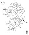
- FIG. 1is a perspective view of a powertrain with an air induction system constructed in accordance with the teachings of the present invention
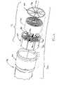
- FIG. 2is an exploded perspective view of a portion of the air induction system of FIG. 1 illustrating the clean air duct in greater detail;
- FIG. 3is a longitudinal section view of a portion of the clean air duct.
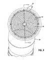
- FIG. 4is an end view of the clean air duct
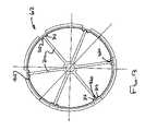
- FIGS. 5 and 6are end views of alternately constructed filter elements
- FIG. 7is a plan view of another hydrocarbon trap assembly constructed in accordance with the teachings of the present invention.
- FIG. 8is a perspective view of a portion of the hydrocarbon trap assembly of FIG. 7 ;
- FIG. 9is an exploded perspective view of another hydrocarbon trap assembly constructed in accordance with the teachings of the present invention.
- FIG. 10is a side view of a portion of the hydrocarbon trap assembly of FIG. 9 illustrating a first one of the comb members in greater detail;
- FIG. 11is a side view of a portion of the hydrocarbon trap assembly of FIG. 9 illustrating a second one of the comb members in greater detail;
- FIG. 12is a side view of a portion of the hydrocarbon trap assembly of FIG. 9 illustrating a third one of the comb members in greater detail.
- FIG. 13is a front view of a portion of the hydrocarbon trap assembly of FIG. 10 illustrating the outer body member of the support.
- an exemplary powertrain of a motor vehicle with an air induction system constructed in accordance with the teachings of the present inventionis generally indicated at reference numeral 10 .
- the powertrain 10includes an engine 12 whose output is transmitted to a transmission 14 .
- the engine 12includes an air induction system 16 that routes air to the engine 12 for use in a combustion event.
- the air induction system 16includes an air filter housing 20 , a primary air filter 22 , an inlet duct 24 and a clean air duct 26 .
- the air filter housing 20includes an inlet which is coupled in fluid connection to the inlet duct 24 and an outlet which is coupled in fluid connection to the clean air duct 26 .
- the primary air filter 22is housed in the air filter housing 20 and filters dirt and debris from the air that is routed into the air filter housing 20 by the inlet duct 24 . Filtered or clean air is routed to an engine intake manifold 30 via the clean air duct 26 .
- the exemplary clean air duct 26 illustratedis an assembly that includes a duct structure 40 and a hydrocarbon trap assembly 42 .
- the duct structure 40may be any type of metal, rubber or plastic tubing or hose and can be a molded/extruded rubber, for example.
- the duct structure 40includes a coupling portion 46 having a stop member 48 , which may be one or more protrusions located along the inside diameter of the duct structure 40 , and a lock portion 50 that may include an outwardly tapering or flared section 52 and an abutting wall 54 .
- the hydrocarbon trap assembly 42may include an element 60 , a support 62 and a lid 64 .
- the element 60may be formed of a sheet paper material that is capable of adsorbing and desorbing gaseous hydrocarbons.
- the sheet paper materialis an activated carbon sheet, such as an ACS-270 product that is commercially available from MeadWestvaco.
- the sheet paper materialhas a sheet density of about 270 pounds per 3000 square feet ( ⁇ 10%) and a minimum working butane capacity of about 5 grams/square foot, but a sheet paper material with a different density, such as 135 pounds per 3000 square feet, and/or a different minimum working butane capacity, such as about 2 grams/square foot, could be used.
- the support 62may include a plurality of fingers or teeth 70 through which the element 60 is woven to thereby form a plurality of flow channels 74 that may be bounded on two sides by the hydrocarbon adsorbing material from which the element 60 is formed.
- the element 60is woven or wound through the teeth 70 in a substantially spiral manner.
- patterns or forms of weaving or windingmay also be employed, such as concentric shapes (e.g., circles 76 ) as shown in FIG. 5 or an alternating tooth-like pattern 78 of the type that is shown in FIG. 6 , for example.
- the element 60need not be formed from a single section of the sheet paper material, but may be formed in the alternative from a plurality of discrete segments of the material. It can be appreciated that although the comb members 90 are illustrated and described herein as being associated with the support 62 , those of ordinary skill in the art can appreciate that in the alternative, the comb members 90 can be associated with another component, such as the lid 64 .
- the support 62may include a plurality of comb members 90 each of which having a set 92 of the teeth 70 .
- the comb members 90may extend generally radially outwardly from a centerline of the support 62 .
- the support 62includes an outer body member 94 , to which the comb members 90 are coupled, and an annular retention lip 96 that may extend partially or fully about the perimeter of the outer body member 94 .
- the lid 64may be coupled to the support 62 via any appropriate means including adhesives, welds, snap fits and fasteners and may cooperate with the support 62 to retain the element 60 in a stationary condition relative to the support 62 .
- the lid 64includes a plurality of ribs or spokes 98 that extend outwardly and which are generally aligned to a respective one of the comb members 90 when the lid 64 and the support 62 are coupled to one another.
- the lid 64 and the support 62may include locking features that permit the lid 64 to be aligned and secured to the support 62 without use of discrete fasteners, adhesives or welds.
- the retention lip 96includes a plurality of apertures 100 and the lid 64 includes a plurality of locking tabs 102 . Insertion of the locking tabs 102 into respective apertures 100 aligns the lid 64 to the support 62 , as well as couples the lid 64 and the support 62 to one another.
- Assembly of the clean air duct 26is accomplished by inserting and securing the hydrocarbon trap assembly 42 to the duct structure 40 .
- the hydrocarbon trap assembly 42is snap-fit into the coupling portion 46 of the duct structure 40 . More particularly, the hydrocarbon trap assembly 42 is inserted into the coupling portion 46 such that the outer body member 94 of the support 62 is abutted against the stop member 48 and the retention lip 96 is received into the outwardly flared section 52 and abutted against the abutting wall 54 .
- gaseous hydrocarbons emitted from the air intake manifold 30 ( FIG. 1 )travel reversely through the duct structure 40 of the clean air duct 26 and pass into the flow channels 74 in the element 60 so that a relatively large amount of the gaseous hydrocarbons may be adsorbed by the element 60 .
- clean air exiting the primary air filter 22 ( FIG. 1 )is directed through the duct structure 40 and passes through the element 60 .
- the flow channels 74permit a relatively large amount of air to pass through the element 60 without developing a significant back pressure that would impair the performance of the powertrain 10 ( FIG. 1 ).
- air passing through the element 60permits the previously adsorbed hydrocarbons to be desorbed into the air stream where they are fed to the engine 12 ( FIG. 1 ).
- the air induction system 10has been illustrated and described above as including a hydrocarbon trap assembly 42 with a support 62 for supporting the element 60 , those of ordinary skill in the art will appreciate that in its broadest aspects, the invention may be constructed somewhat differently.
- the hydrocarbon trap assembly 42may be constructed as illustrated in FIGS. 7 and 8 .
- the hydrocarbon trap assembly 42includes an element 60 , which is formed of a sheet paper material that is capable of adsorbing gaseous hydrocarbons and which includes an integrally formed support 62 .
- the sheet paper materialis an activated carbon sheet, such as an ACS-270 product that is commercially available from MeadWestvaco, and can have a sheet density of about 270 pounds per 3000 square feet ( ⁇ 10%) and a minimum working butane capacity of about 5 grams/square foot.
- ACS-270 productthat is commercially available from MeadWestvaco
- a sheet densityof about 270 pounds per 3000 square feet ( ⁇ 10%) and a minimum working butane capacity of about 5 grams/square foot.
- a sheet paper material with a different densitysuch as 135 pounds per 3000 square feet, and/or a different minimum working butane capacity, such as about 2 grams/square foot, could be used.
- the element 60 of FIGS. 7 and 8is configured to be self-supporting.
- One way in which the element 60 can be made to be self-supportingis through the use of two or more pieces of the sheet material (e.g., 200 a and 200 b ) and the use of slotted apertures 204 that can be formed partially through the pieces of sheet material.
- the slotted apertures 204can be sized and shaped such that when the slotted apertures 204 in a first one of the pieces of sheet material (e.g., 200 a ) are vertically aligned to the slotted apertures 204 in a second one of the pieces of sheet material (e.g.
- the pieces of sheet materialmay be translated toward one another such that an unslotted portion ( 206 ) of each piece of sheet material ( 200 a and 200 b ) may be disposed within an associated one of the slotted apertures 204 .
- the portion of each piece of sheet materialeffectively forms a finger 70 for supporting the other piece of sheet material. Accordingly, it will be appreciated that the interlacing of the pieces of sheet material between the fingers of opposite pieces of sheet material effectively forms a support 62 that is integral to the element 60 .
- the pieces of sheet materialare illustrated as defining generally transverse wall segments 210 (so that the majority of the flow channels 74 are generally square in shape), those of ordinary skill in the art will appreciate that the wall segments 210 may have any desired configuration. Accordingly the majority of the flow channels 74 may be consistently formed with a different shape (e.g., any triangular or parallelogram shape) or with one or more shapes.
- the hydrocarbon trap assembly 42can include a support 62 and a plurality of interlocking comb members 90 a , 90 b and 90 c .
- Each of the comb members 90 a , 90 b and 90 ccan include a pair of comb portions 300 that can be disposed on opposite sides of a hub portion 302 .
- the fingers 70 of each comb portion 300may be fixedly coupled at a first end to a support or structural portion and may be tapered on an opposite end to facilitate assembly of the element therebetween.
- Each hub portion 302may include a locking or orientation feature that permits the hub portion 302 of one comb member (e.g., 90 a ) to be fixedly coupled to the hub portion 302 of an adjacent comb member (e.g., 90 b ).
- the hub portion 302 of comb members 90 a and 90 cinclude a tab recess 306 that is configured to receive a corresponding tab 308 that is formed on the hub portion 302 of the comb member 90 b .
- Those of ordinary skill in the artwill appreciate that various other shapes and configurations may be employed to orient or lock the comb members to one another.
- the hub portion 302is illustrated herein as being generally tubular in shape, other shapes and configurations may be readily substituted therefor.
- the outer body member 94 of the support 62can be configured with a plurality of spokes 310 and ribs 312 that are complementary to the comb portions 300 of the comb members 90 a , 90 b and 90 c .
- grooves 320may be formed into the ribs 312 (and optionally the spokes 310 ) to receive the comb portions 300 .
Landscapes
- Engineering & Computer Science (AREA)
- Chemical & Material Sciences (AREA)
- Combustion & Propulsion (AREA)
- Mechanical Engineering (AREA)
- General Engineering & Computer Science (AREA)
- Analytical Chemistry (AREA)
- General Chemical & Material Sciences (AREA)
- Oil, Petroleum & Natural Gas (AREA)
- Chemical Kinetics & Catalysis (AREA)
- Filtering Of Dispersed Particles In Gases (AREA)
Abstract
Description
Claims (52)
Priority Applications (1)
| Application Number | Priority Date | Filing Date | Title |
|---|---|---|---|
| US11/032,191US7547350B2 (en) | 2005-01-10 | 2005-01-10 | Air induction system with hydrocarbon trap assembly |
Applications Claiming Priority (1)
| Application Number | Priority Date | Filing Date | Title |
|---|---|---|---|
| US11/032,191US7547350B2 (en) | 2005-01-10 | 2005-01-10 | Air induction system with hydrocarbon trap assembly |
Publications (2)
| Publication Number | Publication Date |
|---|---|
| US20060150811A1 US20060150811A1 (en) | 2006-07-13 |
| US7547350B2true US7547350B2 (en) | 2009-06-16 |
Family
ID=36651927
Family Applications (1)
| Application Number | Title | Priority Date | Filing Date |
|---|---|---|---|
| US11/032,191Expired - Fee RelatedUS7547350B2 (en) | 2005-01-10 | 2005-01-10 | Air induction system with hydrocarbon trap assembly |
Country Status (1)
| Country | Link |
|---|---|
| US (1) | US7547350B2 (en) |
Cited By (19)
| Publication number | Priority date | Publication date | Assignee | Title |
|---|---|---|---|---|
| US20070186904A1 (en)* | 2006-02-08 | 2007-08-16 | Mann & Hummel Gmbh | Retention assembly for a hydrocarbon trap |
| US20090301071A1 (en)* | 2008-06-06 | 2009-12-10 | Scott Richard Dobert | Low restriction hydrocarbon trap assembly |
| USD611065S1 (en)* | 2009-01-09 | 2010-03-02 | Amir Rosenbaum | Air intake manifold |
| USD612871S1 (en)* | 2009-01-09 | 2010-03-30 | Amir Rosenbaum | Air intake manifold |
| US20110219953A1 (en)* | 2010-03-09 | 2011-09-15 | Huntair, Inc. | Air filteration system with quick connect |
| US8132559B2 (en) | 2010-07-15 | 2012-03-13 | Ford Global Technologies, Llc | Water/air separator |
| US20120211376A1 (en)* | 2011-02-18 | 2012-08-23 | National Central University | Hydrogen storage apparatus |
| US9932942B2 (en)* | 2014-08-26 | 2018-04-03 | Edmond Pol Jean LePoutre | Flexible porous non-pollutive tube |
| US10807034B2 (en) | 2017-01-31 | 2020-10-20 | Calgon Carbon Corporation | Sorbent devices |
| US11697580B2 (en) | 2018-08-01 | 2023-07-11 | Calgon Carbon Corporation | Apparatus for hydrocarbon vapor recovery |
| US11697090B2 (en) | 2018-08-02 | 2023-07-11 | Calgon Carbon Corporation | Sorbent devices |
| US11703016B2 (en) | 2018-08-02 | 2023-07-18 | Calgon Carbon Corporation | Sorbent devices |
| US11872539B2 (en) | 2020-08-31 | 2024-01-16 | Calgon Carbon Corporation | Copper and nitrogen treated sorbent and method for making same |
| US11911743B2 (en) | 2019-04-03 | 2024-02-27 | Calgon Carbon Corporation | Perfluoroalkyl and polyfluoroalkyl sorbent materials and methods of use |
| US12059668B2 (en) | 2020-08-31 | 2024-08-13 | Calgon Carbon Corporation | Copper, iron, and nitrogen treated sorbent and method for making same |
| US12064745B2 (en) | 2020-08-31 | 2024-08-20 | Calgon Carbon Corporation | Iron and nitrogen treated sorbent and method for making same |
| US12076687B2 (en) | 2019-08-08 | 2024-09-03 | Calgon Carbon Corporation | Sorbent devices for air intakes |
| US12319593B2 (en) | 2020-07-14 | 2025-06-03 | Calgon Carbon Corporation | Sorbents having high volumetric iodine and molasses values for removal of PFAS from fluids and methods of making and using the same |
| US12318758B2 (en) | 2019-07-22 | 2025-06-03 | Calgon Carbon Corporation | Textured sorbent sheets, assemblies containing them, and molds for making same |
Families Citing this family (24)
| Publication number | Priority date | Publication date | Assignee | Title |
|---|---|---|---|---|
| US7294178B2 (en)* | 2004-11-08 | 2007-11-13 | Visteon Global Technologies, Inc. | Low loss hydrocarbon (HC) adsorber device for air induction system |
| US7222612B2 (en)* | 2005-01-27 | 2007-05-29 | Delphi Technologies, Inc. | Low-resistance hydrocarbon adsorber cartridge for an air intake of an internal combustion engine |
| US7278406B2 (en)* | 2005-01-27 | 2007-10-09 | Delphi Technologies, Inc. | Spiral-wound hydrocarbon adsorber for an air intake of an internal combustion engine |
| US9266051B2 (en) | 2005-07-28 | 2016-02-23 | Carbon Sink, Inc. | Removal of carbon dioxide from air |
| EP1998871A4 (en)* | 2006-03-08 | 2010-07-21 | Global Res Technologies Llc | AIR COLLECTOR WITH FUNCTIONALIZED ION EXCHANGE MEMBRANE FOR CAPTURING AMBIENT CO2 |
| US7610904B2 (en)* | 2006-06-22 | 2009-11-03 | Honeywell International Inc. | Hydrocarbon adsorber for air induction systems |
| CN104826450B (en) | 2006-10-02 | 2021-08-27 | 碳汇公司 | Extraction of CO from air2Method and apparatus |
| WO2008131132A1 (en) | 2007-04-17 | 2008-10-30 | Global Research Technologies, Llc | Capture of carbon dioxide (co2) from air |
| CA2715874C (en) | 2008-02-19 | 2019-06-25 | Global Research Technologies, Llc | Extraction and sequestration of carbon dioxide |
| US7918912B2 (en)* | 2008-05-15 | 2011-04-05 | Ford Global Technologies, Llc | Engine hydrocarbon adsorber |
| US8999279B2 (en) | 2008-06-04 | 2015-04-07 | Carbon Sink, Inc. | Laminar flow air collector with solid sorbent materials for capturing ambient CO2 |
| WO2010019600A2 (en)* | 2008-08-11 | 2010-02-18 | Global Research Technologies, Llc | Method and apparatus for extracting carbon dioxide from air |
| US8191535B2 (en)* | 2008-10-10 | 2012-06-05 | Ford Global Technologies, Llc | Sleeve hydrocarbon trap |
| EP2528677B1 (en)* | 2010-01-26 | 2017-08-23 | Micropore, Inc. | Adsorbent system for removal of gaseous contaminants |
| EP2627430A4 (en) | 2010-10-14 | 2014-10-29 | Micropore Inc | Adsorbent cartridge assembly with end cap |
| US20140130765A1 (en)* | 2011-07-01 | 2014-05-15 | Meadwestvaco Corporation | Emission control devices for air intake systems |
| EP4245399A1 (en) | 2012-04-24 | 2023-09-20 | Micropore, Inc. | Durable adsorbent material and adsorbent packs and method of making same |
| US9464605B2 (en)* | 2013-08-24 | 2016-10-11 | Lonn M. Peterson | Quad flow torque enhancement flow divider causing improved fuel/air transfer |
| DE102015008011B4 (en)* | 2015-06-22 | 2020-12-17 | A. Kayser Automotive Systems Gmbh | Activated carbon filter system |
| US10711736B2 (en)* | 2017-12-21 | 2020-07-14 | Mann+Hummel Gmbh | Air cleaner assembly for an internal combustion engine |
| WO2019161114A1 (en) | 2018-02-16 | 2019-08-22 | Carbon Sink, Inc. | Fluidized bed extractors for capture of co2 from ambient air |
| EP3962641A1 (en)* | 2019-04-30 | 2022-03-09 | Exxonmobil Upstream Research Company (EMHC-N1-4A-607) | Rapid cycle adsorbent bed |
| US11686280B2 (en)* | 2019-07-10 | 2023-06-27 | B&M Racing & Performance Products Inc. | Air filter adapter |
| US11506158B2 (en)* | 2020-07-17 | 2022-11-22 | Ford Global Technologies, Llc | Tamper resistant hydrocarbon trap for combustion engines |
Citations (6)
| Publication number | Priority date | Publication date | Assignee | Title |
|---|---|---|---|---|
| US4289513A (en)* | 1978-03-27 | 1981-09-15 | The Mead Corporation | Activated sorbtion paper and products produced thereby |
| US6692551B2 (en) | 2002-07-17 | 2004-02-17 | Delphi Technologies, Inc. | Air cleaner assembly and process |
| US6736115B1 (en) | 2003-02-28 | 2004-05-18 | Visteon Global Technologies, Inc. | Air induction system comprising thermal pump for hydrocarbon vapor control |
| US6736871B1 (en) | 2002-12-09 | 2004-05-18 | Visteon Global Technologies, Inc. | Integrated filter screen and hydrocarbon adsorber |
| US6758885B2 (en) | 2002-02-07 | 2004-07-06 | Visteon Global Technologies, Inc. | Screened carbon trap protection |
| US20060162704A1 (en)* | 2005-01-27 | 2006-07-27 | Hagler Dean R | Low-resistance hydrocarbon adsorber cartridge for an air intake of an internal combustion engine |
- 2005
- 2005-01-10USUS11/032,191patent/US7547350B2/ennot_activeExpired - Fee Related
Patent Citations (6)
| Publication number | Priority date | Publication date | Assignee | Title |
|---|---|---|---|---|
| US4289513A (en)* | 1978-03-27 | 1981-09-15 | The Mead Corporation | Activated sorbtion paper and products produced thereby |
| US6758885B2 (en) | 2002-02-07 | 2004-07-06 | Visteon Global Technologies, Inc. | Screened carbon trap protection |
| US6692551B2 (en) | 2002-07-17 | 2004-02-17 | Delphi Technologies, Inc. | Air cleaner assembly and process |
| US6736871B1 (en) | 2002-12-09 | 2004-05-18 | Visteon Global Technologies, Inc. | Integrated filter screen and hydrocarbon adsorber |
| US6736115B1 (en) | 2003-02-28 | 2004-05-18 | Visteon Global Technologies, Inc. | Air induction system comprising thermal pump for hydrocarbon vapor control |
| US20060162704A1 (en)* | 2005-01-27 | 2006-07-27 | Hagler Dean R | Low-resistance hydrocarbon adsorber cartridge for an air intake of an internal combustion engine |
Non-Patent Citations (1)
| Title |
|---|
| MeadWestvaco ACS-135/270 Product Data Bulletin. Copyright 2002. |
Cited By (23)
| Publication number | Priority date | Publication date | Assignee | Title |
|---|---|---|---|---|
| US20070186904A1 (en)* | 2006-02-08 | 2007-08-16 | Mann & Hummel Gmbh | Retention assembly for a hydrocarbon trap |
| US7895983B2 (en)* | 2006-02-08 | 2011-03-01 | Mann + Hommel GmbH | Retention assembly for a hydrocarbon trap |
| US20090301071A1 (en)* | 2008-06-06 | 2009-12-10 | Scott Richard Dobert | Low restriction hydrocarbon trap assembly |
| US8205442B2 (en)* | 2008-06-06 | 2012-06-26 | Visteon Global Technologies, Inc. | Low restriction hydrocarbon trap assembly |
| USD611065S1 (en)* | 2009-01-09 | 2010-03-02 | Amir Rosenbaum | Air intake manifold |
| USD612871S1 (en)* | 2009-01-09 | 2010-03-30 | Amir Rosenbaum | Air intake manifold |
| US20110219953A1 (en)* | 2010-03-09 | 2011-09-15 | Huntair, Inc. | Air filteration system with quick connect |
| US8419837B2 (en)* | 2010-03-09 | 2013-04-16 | Huntair, Inc. | Air filtration system with quick connect |
| US8132559B2 (en) | 2010-07-15 | 2012-03-13 | Ford Global Technologies, Llc | Water/air separator |
| US20120211376A1 (en)* | 2011-02-18 | 2012-08-23 | National Central University | Hydrogen storage apparatus |
| US9932942B2 (en)* | 2014-08-26 | 2018-04-03 | Edmond Pol Jean LePoutre | Flexible porous non-pollutive tube |
| US10807034B2 (en) | 2017-01-31 | 2020-10-20 | Calgon Carbon Corporation | Sorbent devices |
| US11697091B2 (en) | 2017-01-31 | 2023-07-11 | Calgon Carbon Corporation | Sorbent devices |
| US11697580B2 (en) | 2018-08-01 | 2023-07-11 | Calgon Carbon Corporation | Apparatus for hydrocarbon vapor recovery |
| US11697090B2 (en) | 2018-08-02 | 2023-07-11 | Calgon Carbon Corporation | Sorbent devices |
| US11703016B2 (en) | 2018-08-02 | 2023-07-18 | Calgon Carbon Corporation | Sorbent devices |
| US11911743B2 (en) | 2019-04-03 | 2024-02-27 | Calgon Carbon Corporation | Perfluoroalkyl and polyfluoroalkyl sorbent materials and methods of use |
| US12318758B2 (en) | 2019-07-22 | 2025-06-03 | Calgon Carbon Corporation | Textured sorbent sheets, assemblies containing them, and molds for making same |
| US12076687B2 (en) | 2019-08-08 | 2024-09-03 | Calgon Carbon Corporation | Sorbent devices for air intakes |
| US12319593B2 (en) | 2020-07-14 | 2025-06-03 | Calgon Carbon Corporation | Sorbents having high volumetric iodine and molasses values for removal of PFAS from fluids and methods of making and using the same |
| US11872539B2 (en) | 2020-08-31 | 2024-01-16 | Calgon Carbon Corporation | Copper and nitrogen treated sorbent and method for making same |
| US12059668B2 (en) | 2020-08-31 | 2024-08-13 | Calgon Carbon Corporation | Copper, iron, and nitrogen treated sorbent and method for making same |
| US12064745B2 (en) | 2020-08-31 | 2024-08-20 | Calgon Carbon Corporation | Iron and nitrogen treated sorbent and method for making same |
Also Published As
| Publication number | Publication date |
|---|---|
| US20060150811A1 (en) | 2006-07-13 |
Similar Documents
| Publication | Publication Date | Title |
|---|---|---|
| US7547350B2 (en) | Air induction system with hydrocarbon trap assembly | |
| US11007462B2 (en) | Air cleaner; replaceable filter cartridges; and, methods | |
| US9206721B2 (en) | Cyclonic air cleaner | |
| CN101282775B (en) | air filter assembly | |
| US8029586B2 (en) | Filter pipeline | |
| US7211124B2 (en) | Filter element, air cleaner, and methods | |
| US7927393B2 (en) | Air cleaner element | |
| US7699042B2 (en) | Filtration device for use with a fuel vapor recovery system | |
| US20250161856A1 (en) | Filter elements, air cleaner assemblies, and methods of use and assembly | |
| US20070137152A1 (en) | Precleaner arrangement for use in air filtration, method of operation of precleaner and air cleaner comprising the precleaner arrangement | |
| US20140165542A1 (en) | Emission control devices for air intake systems | |
| US9662968B2 (en) | Mounting assembly for a diesel oxidation catalyst system of a work vehicle | |
| US20040211320A1 (en) | Integration of a metallic substrate into a plastic induction system | |
| US20090120046A1 (en) | Hydrocarbon Adsorber with Purge Airflow Channel | |
| WO2016167958A1 (en) | Detachable and reversible pre-cleaner for filter assembly | |
| US9909543B2 (en) | Air intake system for a work vehicle with enhanced pre-cleaner serviceability | |
| US8506664B2 (en) | Filter pipeline | |
| US6902595B2 (en) | Intake water separator | |
| US11686280B2 (en) | Air filter adapter | |
| US11642616B2 (en) | Filter for in-line or inlet applications | |
| KR101883159B1 (en) | Air cleaner for vehicles | |
| JP2003502559A (en) | Manifold housing | |
| KR101562872B1 (en) | Air cleaner for vehicle |
Legal Events
| Date | Code | Title | Description |
|---|---|---|---|
| AS | Assignment | Owner name:MINIATURE PRECISION COMPONENTS, INC., MICHIGAN Free format text:ASSIGNMENT OF ASSIGNORS INTEREST;ASSIGNORS:CALLAHAN, DOUGLAS J.;VAN DE BOGERT, MARK T.;REEL/FRAME:021594/0124;SIGNING DATES FROM 20050106 TO 20050107 | |
| STCF | Information on status: patent grant | Free format text:PATENTED CASE | |
| AS | Assignment | Owner name:JPMORGAN CHASE BANK, N.A., ILLINOIS Free format text:SECURITY AGREEMENT;ASSIGNOR:MINIATURE PRECISION COMPONENTS, INC.;REEL/FRAME:026746/0547 Effective date:20110805 | |
| FPAY | Fee payment | Year of fee payment:4 | |
| FPAY | Fee payment | Year of fee payment:8 | |
| AS | Assignment | Owner name:NOVARES US ENGINE COMPONENTS, INC., WISCONSIN Free format text:CHANGE OF NAME;ASSIGNOR:MINIATURE PRECISION COMPONENTS, INC.;REEL/FRAME:053668/0992 Effective date:20190930 | |
| FEPP | Fee payment procedure | Free format text:MAINTENANCE FEE REMINDER MAILED (ORIGINAL EVENT CODE: REM.); ENTITY STATUS OF PATENT OWNER: LARGE ENTITY | |
| LAPS | Lapse for failure to pay maintenance fees | Free format text:PATENT EXPIRED FOR FAILURE TO PAY MAINTENANCE FEES (ORIGINAL EVENT CODE: EXP.); ENTITY STATUS OF PATENT OWNER: LARGE ENTITY | |
| STCH | Information on status: patent discontinuation | Free format text:PATENT EXPIRED DUE TO NONPAYMENT OF MAINTENANCE FEES UNDER 37 CFR 1.362 | |
| FP | Lapsed due to failure to pay maintenance fee | Effective date:20210616 |