US7547336B2 - Vacuum cleaner with multiple cyclonic dirt separators and bottom discharge dirt cup - Google Patents
Vacuum cleaner with multiple cyclonic dirt separators and bottom discharge dirt cupDownload PDFInfo
- Publication number
- US7547336B2 US7547336B2US11/275,120US27512005AUS7547336B2US 7547336 B2US7547336 B2US 7547336B2US 27512005 AUS27512005 AUS 27512005AUS 7547336 B2US7547336 B2US 7547336B2
- Authority
- US
- United States
- Prior art keywords
- cyclone
- cyclonic
- vacuum cleaner
- secondary cyclones
- side wall
- Prior art date
- Legal status (The legal status is an assumption and is not a legal conclusion. Google has not performed a legal analysis and makes no representation as to the accuracy of the status listed.)
- Active, expires
Links
- JTJMJGYZQZDUJJ-UHFFFAOYSA-NphencyclidineChemical groupC1CCCCN1C1(C=2C=CC=CC=2)CCCCC1JTJMJGYZQZDUJJ-UHFFFAOYSA-N0.000claimsabstractdescription112
- 239000000356contaminantSubstances0.000claimsabstractdescription16
- 239000000463materialSubstances0.000claimsdescription6
- 230000008878couplingEffects0.000claimsdescription3
- 238000010168coupling processMethods0.000claimsdescription3
- 238000005859coupling reactionMethods0.000claimsdescription3
- 239000003381stabilizerSubstances0.000abstractdescription8
- 239000002245particleSubstances0.000description13
- 238000000926separation methodMethods0.000description8
- 238000011144upstream manufacturingMethods0.000description6
- 230000005484gravityEffects0.000description3
- 239000011163secondary particleSubstances0.000description3
- 230000008901benefitEffects0.000description2
- 239000000428dustSubstances0.000description2
- 239000012530fluidSubstances0.000description2
- 230000007246mechanismEffects0.000description2
- 230000009471actionEffects0.000description1
- 239000000853adhesiveSubstances0.000description1
- 230000001070adhesive effectEffects0.000description1
- 238000013459approachMethods0.000description1
- 230000008859changeEffects0.000description1
- 238000004140cleaningMethods0.000description1
- 238000004891communicationMethods0.000description1
- 238000000151depositionMethods0.000description1
- 239000006260foamSubstances0.000description1
- 239000003112inhibitorSubstances0.000description1
- 238000003780insertionMethods0.000description1
- 230000037431insertionEffects0.000description1
- 230000013011matingEffects0.000description1
- 238000000034methodMethods0.000description1
- 230000004048modificationEffects0.000description1
- 238000012986modificationMethods0.000description1
- 239000011236particulate materialSubstances0.000description1
- 239000013618particulate matterSubstances0.000description1
- 238000004513sizingMethods0.000description1
- 239000007787solidSubstances0.000description1
- 238000003466weldingMethods0.000description1
Images


Classifications
- A—HUMAN NECESSITIES
- A47—FURNITURE; DOMESTIC ARTICLES OR APPLIANCES; COFFEE MILLS; SPICE MILLS; SUCTION CLEANERS IN GENERAL
- A47L—DOMESTIC WASHING OR CLEANING; SUCTION CLEANERS IN GENERAL
- A47L9/00—Details or accessories of suction cleaners, e.g. mechanical means for controlling the suction or for effecting pulsating action; Storing devices specially adapted to suction cleaners or parts thereof; Carrying-vehicles specially adapted for suction cleaners
- A47L9/10—Filters; Dust separators; Dust removal; Automatic exchange of filters
- A47L9/16—Arrangement or disposition of cyclones or other devices with centrifugal action
- A47L9/1658—Construction of outlets
- A47L9/1666—Construction of outlets with filtering means
- A—HUMAN NECESSITIES
- A47—FURNITURE; DOMESTIC ARTICLES OR APPLIANCES; COFFEE MILLS; SPICE MILLS; SUCTION CLEANERS IN GENERAL
- A47L—DOMESTIC WASHING OR CLEANING; SUCTION CLEANERS IN GENERAL
- A47L9/00—Details or accessories of suction cleaners, e.g. mechanical means for controlling the suction or for effecting pulsating action; Storing devices specially adapted to suction cleaners or parts thereof; Carrying-vehicles specially adapted for suction cleaners
- A47L9/10—Filters; Dust separators; Dust removal; Automatic exchange of filters
- A47L9/12—Dry filters
- A47L9/122—Dry filters flat
- A—HUMAN NECESSITIES
- A47—FURNITURE; DOMESTIC ARTICLES OR APPLIANCES; COFFEE MILLS; SPICE MILLS; SUCTION CLEANERS IN GENERAL
- A47L—DOMESTIC WASHING OR CLEANING; SUCTION CLEANERS IN GENERAL
- A47L9/00—Details or accessories of suction cleaners, e.g. mechanical means for controlling the suction or for effecting pulsating action; Storing devices specially adapted to suction cleaners or parts thereof; Carrying-vehicles specially adapted for suction cleaners
- A47L9/10—Filters; Dust separators; Dust removal; Automatic exchange of filters
- A47L9/16—Arrangement or disposition of cyclones or other devices with centrifugal action
- A47L9/1616—Multiple arrangement thereof
- A47L9/1625—Multiple arrangement thereof for series flow
- A—HUMAN NECESSITIES
- A47—FURNITURE; DOMESTIC ARTICLES OR APPLIANCES; COFFEE MILLS; SPICE MILLS; SUCTION CLEANERS IN GENERAL
- A47L—DOMESTIC WASHING OR CLEANING; SUCTION CLEANERS IN GENERAL
- A47L9/00—Details or accessories of suction cleaners, e.g. mechanical means for controlling the suction or for effecting pulsating action; Storing devices specially adapted to suction cleaners or parts thereof; Carrying-vehicles specially adapted for suction cleaners
- A47L9/10—Filters; Dust separators; Dust removal; Automatic exchange of filters
- A47L9/16—Arrangement or disposition of cyclones or other devices with centrifugal action
- A47L9/1616—Multiple arrangement thereof
- A47L9/1641—Multiple arrangement thereof for parallel flow
- A—HUMAN NECESSITIES
- A47—FURNITURE; DOMESTIC ARTICLES OR APPLIANCES; COFFEE MILLS; SPICE MILLS; SUCTION CLEANERS IN GENERAL
- A47L—DOMESTIC WASHING OR CLEANING; SUCTION CLEANERS IN GENERAL
- A47L9/00—Details or accessories of suction cleaners, e.g. mechanical means for controlling the suction or for effecting pulsating action; Storing devices specially adapted to suction cleaners or parts thereof; Carrying-vehicles specially adapted for suction cleaners
- A47L9/10—Filters; Dust separators; Dust removal; Automatic exchange of filters
- A47L9/16—Arrangement or disposition of cyclones or other devices with centrifugal action
- A47L9/1683—Dust collecting chambers; Dust collecting receptacles
- B—PERFORMING OPERATIONS; TRANSPORTING
- B04—CENTRIFUGAL APPARATUS OR MACHINES FOR CARRYING-OUT PHYSICAL OR CHEMICAL PROCESSES
- B04C—APPARATUS USING FREE VORTEX FLOW, e.g. CYCLONES
- B04C5/00—Apparatus in which the axial direction of the vortex is reversed
- B04C5/14—Construction of the underflow ducting; Apex constructions; Discharge arrangements ; discharge through sidewall provided with a few slits or perforations
- B04C5/185—Dust collectors
- B—PERFORMING OPERATIONS; TRANSPORTING
- B04—CENTRIFUGAL APPARATUS OR MACHINES FOR CARRYING-OUT PHYSICAL OR CHEMICAL PROCESSES
- B04C—APPARATUS USING FREE VORTEX FLOW, e.g. CYCLONES
- B04C5/00—Apparatus in which the axial direction of the vortex is reversed
- B04C5/24—Multiple arrangement thereof
- B04C5/26—Multiple arrangement thereof for series flow
- B—PERFORMING OPERATIONS; TRANSPORTING
- B04—CENTRIFUGAL APPARATUS OR MACHINES FOR CARRYING-OUT PHYSICAL OR CHEMICAL PROCESSES
- B04C—APPARATUS USING FREE VORTEX FLOW, e.g. CYCLONES
- B04C5/00—Apparatus in which the axial direction of the vortex is reversed
- B04C5/24—Multiple arrangement thereof
- B04C5/28—Multiple arrangement thereof for parallel flow
- Y—GENERAL TAGGING OF NEW TECHNOLOGICAL DEVELOPMENTS; GENERAL TAGGING OF CROSS-SECTIONAL TECHNOLOGIES SPANNING OVER SEVERAL SECTIONS OF THE IPC; TECHNICAL SUBJECTS COVERED BY FORMER USPC CROSS-REFERENCE ART COLLECTIONS [XRACs] AND DIGESTS
- Y10—TECHNICAL SUBJECTS COVERED BY FORMER USPC
- Y10S—TECHNICAL SUBJECTS COVERED BY FORMER USPC CROSS-REFERENCE ART COLLECTIONS [XRACs] AND DIGESTS
- Y10S55/00—Gas separation
- Y10S55/03—Vacuum cleaner
Definitions
- the inventionrelates to a vacuum cleaner with a cyclonic dirt separator having a first cyclone and a plurality of downstream secondary cyclones.
- the inventionrelates to a cyclonic dirt separator with secondary cyclones arranged around the first cyclone to provide an unobstructed view of at least a portion of the first cyclone.
- the inventionrelates to a cyclonic dirt separator with a dirt cup assembly mounted below the cyclones and a working air conduit that extends through the first cyclone and the dirt cup assembly.
- the inventionrelates to a cyclonic dirt separator with secondary cyclones having a vortex stabilizer.
- Cyclone separatorsare well-known. Some follow the textbook examples using frustoconical shape separators, and others use high-speed rotational motion of the air/dirt to separate the dirt by centrifugal force. Typically, working air enters and exits at an upper portion of the cyclone separator, and the bottom portion of the cyclone separator is used to collect debris. Furthermore, in an effort to efficiently distribute weight of and upright vacuum cleaner, the suction source that creates the working air flow is typically placed at the bottom of a handle assembly and below the cyclone separator. This arrangement, therefore, requires an exhaust air path from an upper portion of the cyclone assembly and down the handle to the suction source. This airpath can be tortuous and formed by multiple parts that can allow for air leaks, which negatively impact airflow and, necessarily, cleaning performance.
- U.S. Pat. No. 6,238,451 to Conraddiscloses a cyclonic separator in a vacuum cleaner comprising a single first stage cyclone and a plurality of vertically aligned secondary downstream cyclones arranged in parallel relative to one another.
- the secondary cyclonesare located within the same perimeter of and directly above the upstream cyclone. This arrangement of cyclones necessarily creates a tall unit because the downstream cyclones are located above the upstream cyclone.
- U.S. Pat. No. 6,607,572 to Dysondiscloses a cyclonic separating apparatus with upstream and downstream cyclonic units, wherein the downstream units comprise a plurality of downstream cyclones located above the upstream cyclone and inverted relative to the upstream cyclone.
- U.S. Pat. No. 6,341,404 to Salo et al.discloses a bottom discharge cyclone chamber with the suction source mounted horizontally below the cyclone chamber.
- motor exhaust airis redirected back up into an annular exhaust plenum located below the cyclone chamber, and the motor exhaust exits from the exhaust plenum in a radial fashion.
- This exhaust pathincludes a number of turns, which tend to create backpressure and, therefore, reduce efficiency.
- U.S. Pat. No. 6,129,775 to Conraddiscloses a cyclone separator with a number of different forms of flow inhibitors, such as a terminal insert, to interfere with airflow within the cyclone separator.
- the terminal insertcan comprise a plurality of longitudinally extending members, such as rods, which extend upwardly into the cyclone separator cavity from the bottom surface of the cyclone separator.
- the rodsare said to interact with circulating fluid to disrupt its rotational motion.
- the rodscan be positioned symmetrically or non-symmetrically around longitudinal axis of the separator.
- the rodscan be a variety of shapes such as, in transverse section, squares, ellipses or other closed convex or abode shapes. Further, the transverse section of rods can vary longitudinally.
- U.S. Patent Application Publication No. 2005/00500678 to Oh et al. and its progenydisclose a cyclone dust separating apparatus comprising a primary cyclone and a plurality of downstream secondary cyclones arranged around the primary cyclone.
- the secondary cyclonesobstruct the view of the primary cyclone, and the user cannot visually observe the operation of the primary cyclone.
- the working air exiting the secondary cyclonesexits the cyclone dust separating apparatus through an upper opening.
- a vacuum cleanercomprises a cyclonic separator that includes a first cyclone having a side wall defining a first cyclonic chamber for separating contaminants from an air stream as the air stream travels about the first cyclonic chamber from an air inlet to an air outlet, and a plurality of secondary cyclones downstream from the first cyclone and arranged around the side wall of the first cyclone, each of the secondary cyclones having a side wall defining a second cyclonic chamber for further separating contaminants from the air stream as the air stream travels about the second cyclonic chamber from an air inlet to an air outlet thereof.
- the vacuum cleanerfurther includes a nozzle housing including a suction opening fluidly coupled with the air inlet of the first cyclonic chamber and a suction source coupled to the suction opening and to the first and second cyclonic chambers and adapted to establish and maintain the air stream from the suction opening, through the first cyclonic airflow chamber, and through the second cyclonic airflow chambers.
- the secondary cyclonesform at least one gap between adjacent secondary cyclones, and the first cyclone side wall is exposed to the outside of the cyclonic separator at the at least one gap.
- the first cyclone side wallis preferably formed of a translucent material at least at the at least one gap to provide an unobstructed view of the first cyclonic airflow chamber through the first cyclone side wall and through the at least one gap in the secondary cyclones.
- the vacuum cleanertypically further comprises an upright housing with an opening that receives the cyclonic separator, and the at least one gap is formed at a front portion of the cyclonic separator for an unobstructed view of the first cyclone side wall when the cyclonic separator is mounted to the upright housing.
- the air inlet to the first cycloneis positioned in the side wall of the first cyclone and distal from the at least one gap.
- the secondary cyclonesform two gaps, and the air inlet to the first cyclone is positioned in one of the two gaps.
- the two gapsare formed at opposite sides of first cyclone side wall.
- a vacuum cleanerfurther includes a dirt cup assembly mounted beneath the cyclonic dirt separator to collect the contaminants separated by the first cyclonic chamber and the second cyclonic chambers; and a working air conduit extending through the first cyclone and the dirt cup assembly and fluidly coupling the air outlets of the second cyclonic chambers to an inlet of the suction source.
- the secondary cyclonesare arranged in groups.
- one of the groups of secondary cyclonescomprises four of the secondary cyclones, and another of the groups comprises five of the secondary cyclones.
- each of the groups of secondary cyclonesis enclosed by a side wall spaced from the first cyclone side wall.
- the enclosing side wall of the groups of secondary cyclonesis translucent.
- the secondary cyclonesare arranged in parallel.
- the secondary cycloneshave a generally vertical central longitudinal axis parallel to a central longitudinal axis of the first cyclone.
- the secondary cyclonesare frustoconical, and the first cyclone is cylindrical.
- the dirt cup assemblycomprises a first collecting region for collecting the contaminants separated in the first cyclonic chamber and a second collecting region for collecting the contaminants separated in the second cyclonic chamber.
- the second collecting regionis formed by a collecting cup positioned in the first collecting region.
- a filter assemblyis mounted between the working air conduit and the inlet of the suction source. Further, the working air conduit extends through a central portion of the first collecting region of the dirt cup assembly in a preferred embodiment of the invention.
- At least one of the secondary cycloneshas a vortex stabilizer.
- all of the secondary cycloneshave a vortex stabilizer.
- the secondary cyclonesare frustoconical.
- the vortex stabilizeris located at a bottom portion of the secondary cyclone.
- the vortex stabilizercan comprise a stabilizer plate.
- a debris outletcan be formed in the side wall of the secondary cyclone adjacent to the stabilizer plate.
- the air inlet and air outlet of the secondary cyclonecan be located at an upper portion of the secondary cyclone.
- FIG. 1is a perspective view of an upright vacuum cleaner with a cyclonic dirt separator and dirt cup assembly according to the invention.
- FIG. 2is a sectional view taken along line 2 - 2 of FIG. 1 .
- FIG. 3is an exploded perspective view of a cyclonic separator assembly of the cyclonic dirt separator and dirt cup assembly of FIG. 1 .
- FIG. 4is a sectional view taken along line 4 - 4 of FIG. 1 .
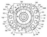
- FIG. 5is a sectional view taken along line 5 - 5 of FIG. 4 .
- FIG. 6is a sectional view taken along line 6 - 6 of FIG. 3 .
- FIG. 7is an exploded perspective view of a dirt cup assembly from the cyclonic dirt separator and dirt cup assembly of FIG. 1 .
- an upright vacuum cleaner 10comprises an upright handle housing 14 with a handle grip 13 formed at an upper end and pivotally mounted to a nozzle base housing 16 at a lower end.
- the nozzle base housing 16comprises a suction nozzle opening 11 on a forward portion thereof.
- the upright handle housing 14has an opening 15 that receives a cyclonic dirt separator and dirt cup assembly 12 comprising a cyclone separator assembly 18 and a dirt cup assembly 54 .
- the dirt cup assembly 54is removably mounted to the upright handle housing 14 and includes a grip 23 to facilitate insertion and removal of the dirt cup assembly 54 .
- the grip 23can be separately formed and attached to the dirt cup assembly 54 in a commonly known manner, such as with screws. However, the grip 23 can also be integrally formed with the dirt cup assembly 54 or can be fastened in other commonly known ways, such as with adhesives or ultrasonic welding.
- the cyclone separator assembly 18comprises a cyclone housing 27 having a primary separation region with a primary cyclone 19 and a secondary separation region that receives a plurality of secondary cyclones 102 .
- the primary separation regionis formed by a generally cylindrical primary separator side wall 17 and has a generally vertical central longitudinal axis A.
- a primary separator upper wall 35which is best viewed in FIGS. 2 and 4 , extends in a generally horizontal orientation near an upper end of the primary separator side wall 17 .
- An annular collar 26is formed centrally in the primary separator upper wall 35 such that the annular collar 26 is centered within the primary separation region.
- the secondary separation regionis separated into two regions, with each of the regions enclosed at its perimeter by a secondary region side wall 22 radially spaced from the primary separator side wall 17 and joined to the primary separator side wall 17 near a lower end by a bottom wall 25 that extends in a perpendicular manner from an inside surface of the secondary region side wall 22 to an outside surface of the generally cylindrical primary separator side wall 17 .
- the secondary region side walls 22 and exposed portions 21 of the generally cylindrical primary separator side wall 17 between the secondary region side walls 22which all terminate in a lower offset lip 24 , form an exterior surface of the cyclone housing 27 .
- the exposed portions 21 of the primary separator side wall 17are exposed to the outside of the cyclonic dirt separator and dirt cup assembly 12 .
- a cyclone cap 20 mounted to an upper end of the cyclone housing 27defines a top for the cyclone separator assembly 18 , and a secondary air manifold 29 is supported between the cyclone housing 27 and the cyclone cap 20 .
- the secondary air manifold 29comprises a depending hollow air duct 92 that extends through the collar 26 into the primary cyclone region.
- a tangential air inlet 28extends through one of the secondary region side walls 22 and the primary separator side wall 17 proximate the primary separator upper wall 35 for generating a tangential airflow into the primary separation region.
- an exhaust assembly 30is mounted to the annular collar 26 in the primary separation region.
- the exhaust assembly 30includes a hollow cylindrical cage 32 that terminates at a lower end at a radially extending separator plate 34 having an outer edge 52 .
- a plurality of apertures 36are formed in an axial alignment in the cage 32 above the separator plate 34 .
- the cage 32defines a working air path; air enters the path by flowing radially inward through the apertures 36 and then upward through the hollow cage 32 .
- the cage 32 and the separator plate 34are removably mounted to the annular collar 26 in the primary cyclone region via a bayonet-type fitting between a projection on the annular collar 26 and a slot 31 on the cage 32 to provide a twist and lock connection.
- a bayonet-type fittingbetween a projection on the annular collar 26 and a slot 31 on the cage 32 to provide a twist and lock connection.
- other mechanical fastening meansto removably mount the exhaust assembly 30 to the annular collar 26 .
- friction fits, ramped threads, detents, or any other commonly known fastening methodcan be utilized.
- a primary cyclonic toroidal chamber 48is defined horizontally between the cage 32 and the primary separator side wall 17 and vertically between the primary separator upper wall 35 and the separator plate 34 .
- the tangential air inlet 28is vertically aligned between the primary separator upper wall 35 and the separator plate 34 and slightly inclined such that the tangential airflow generated from the tangential air inlet 28 is directed in a slightly downward direction tangentially into the primary cyclonic toroidal chamber 48 .
- a working airflowwhich is represented by arrows, containing particulate matter, passes through the tangential air inlet 28 and into the primary cyclonic toroidal chamber 48 , where it travels around the exhaust assembly 30 .
- heavier dirt particles P 1are forced toward the primary separator side wall 17 . Due to gravity and axial components of the forces imparted by the working air, the particles P 1 fall through a gap 50 defined between the edge 52 of the separator plate 34 and the primary separator side wall 17 .
- the particles P 1 that fall through the gap 50continue to fall into the dirt cup assembly 54 , where they are collected in a primary dirt collection region 56 of the dirt cup assembly 54 .
- the primary dirt collecting region 56thereby performs the function of collecting the particles P 1 separated from the airflow within the primary cyclone 19 .
- the working airtraverses through the primary cyclonic toroidal chamber 48 and casts the particles P 1 toward the primary separator side wall 17 , the working air is drawn inwardly through the apertures 36 of the exhaust assembly 30 .
- the apertures 36have an oblong shape, but the apertures 36 can have any suitable geometry that prevents the particles P 1 from exiting the primary cyclonic toroidal chamber 48 through the apertures 36 . Rather, the particles P 1 are urged toward the gap 50 by the circulating airflow in the primary cyclonic toroidal chamber 48 .
- the working air that exits the primary cyclonic toroidal chamber 48 through the apertures 36continues through a secondary cyclone toroidal path 90 formed between an inner surface of the exhaust assembly 30 and an outer solid surface of the air duct 92 depending from the secondary air manifold 29 in a coaxial relationship relative to the exhaust assembly 30 .
- the secondary cyclone toroidal path 90can also be viewed in FIG. 5 .
- the secondary cyclone toroidal path 90directs the working air from the primary cyclone 19 to the secondary air manifold 29 , which directs the working air to the plurality of secondary cyclones 102 located in the secondary cyclone region.
- the secondary cyclones 102are arranged around the primary separator side wall 17 of the primary cyclone 19 in the two regions of the secondary cyclone region.
- the secondary cyclones 102are arranged in two groups, a right group 102 A and a left group 102 B, with the right and left groups 102 A, 102 B corresponding to the two regions and positioned on opposite sides of a vertical plane B ( FIG. 5 ) that includes the central longitudinal axis A and extends from back to front to effectively cut the cyclone separator assembly 18 in half.
- a front gap 98is formed between adjacent secondary cyclones 102 at a front side of the cyclone separator assembly 18
- a rear gap 100is formed between adjacent secondary cyclones 102 at a rear side of the cyclone separator assembly 18 .
- the front and rear gaps 98 , 100are located diametrically opposite each other.
- the tangential air inlet 28is positioned in the rear gap 100 near the right group 102 A.
- the front and rear gaps 98 , 100are coincident with the exposed portions 21 of the primary separator side wall 17 ; therefore, none of the secondary cyclones 102 are located in front of the exposed portions 21 of the primary separator side wall 17 to obstruct view of the exposed portions 21 .
- the exposed portions 21 of the primary separator side wall 17can be made of a transparent or translucent material to allow the user to view the primary cyclonic toroidal chamber 48 through the front and rear gaps 98 , 100 and through the exposed portions 21 of the primary separator side wall 17 .
- the front gap 98is viewable when the cyclone separator assembly 18 is mounted in the opening 15 of the upright handle housing 14 , as shown in FIG. 1 .
- the secondary region side wall 22can be made of a transparent or translucent material to allow a user to view the secondary cyclones 102 .
- the right group 102 Aincludes four of the secondary cyclones 102
- the left group 102 Bincludes five of the secondary cyclones 102 ; however, it is within the scope of the invention for the right and left groups 102 A, 102 B to comprise any suitable number of the secondary cyclones 102 . Further, it is within the scope of the invention to group the secondary cyclones 102 into more than two groups. Alternatively, all of the secondary cyclones 102 can be located on one side of the plane B, wherein the number of the secondary cyclones 102 can range from between one and ten or between three and seven. According to one embodiment, five of the secondary cyclones 102 are located all on one side of the plane B.
- the secondary cyclones 102each comprise a frustoconical housing having a side wall 104 that defines a secondary cyclonic chamber 101 .
- Each side wall 104has an upper, larger end 106 that defines an aperture 118 that functions as both an air inlet and an air outlet for the secondary cyclonic chamber 101 , as will be described in more detail below, and a lower, smaller end 110 forming a secondary debris outlet 120 through which particles P 2 separated from the working air passes to a secondary dirt collecting region 58 of the dirt cup assembly 54 .
- the secondary cyclones 102 in each of the groups 102 A, 102 Bare connected to one another at the larger ends 106 via a housing support 105 that can either be a separate piece or integrally molded with the side walls 104 .
- Each of the secondary cyclones 102has a central longitudinal axis C ( FIG. 2 ) parallel with the central longitudinal axis A of the primary cyclone 19 .
- the central longitudinal axes A, C of the primary cyclone 19 and the secondary cyclones 102are generally vertical.
- one or more of the central longitudinal axes A, Ccan be inclined relative to the vertical, and the secondary cyclones 102 can be inverted such that the larger end 106 is below the smaller end 110 .
- the aperture 118 at the larger end 106 of the side wall 104has a surface area about ten times larger than that of the secondary debris outlet 120 at the smaller end 110 .
- acceptable performanceis obtained within a ratio of the larger end 106 to the smaller end 110 ranging between about two to one and about twenty to one, preferably between about three and a half to one and about eight and a half to one.
- the secondary region side wall 22is tapered to correspond to the shapes of the secondary cyclones 102 located within the secondary region side wall 22 .
- the secondary region side wall 22tapers from its upper end, where it abuts the cyclone cap 20 , to its lower end, which is at the offset lip 24 .
- the secondary air manifold 29is positioned between the cyclone housing 27 and the cyclone cap 20 .
- an air manifold gasket 125is positioned between the secondary air manifold 29 and the cyclone housing 27 to form an airtight seal therebetween.
- a plurality of working air inlet passageways 119which are best viewed in FIG. 6 , are formed in the secondary air manifold 29 for dividing the working air that flows from the secondary cyclone toroidal path 90 and directing the divided working air into each of the secondary cyclones 102 .
- the number of the working air inlet passageways 119equals the number of the secondary cyclones 102 ; each of the working air inlet passageways 119 corresponds to one of the secondary cyclones 102 . Referring back to FIGS. 2-4 , each of the working air inlet passageways 119 terminates at the aperture 118 of the corresponding secondary cyclone 102 to form an inlet 121 to the secondary cyclones 102 .
- the working airexits the secondary cyclones 102 through corresponding working air outlets 122 formed in the secondary air manifold 29 and received by the corresponding apertures 118 .
- the number of the working air outlets 122equals the number of the secondary cyclones 102 ; each of the working air outlets 122 corresponds to one of the secondary cyclones 102 .
- the surface area of the smaller end 110 of the secondary cyclones 102is about equal to or greater than the surface area of the working air outlet 122 .
- the working air outlets 122fluidly communicate with a working air exhaust chamber 123 formed between an upper surface of the secondary air manifold 29 and a lower surface of the cyclone cap 20 .
- the working air exhaust chamber 123is in fluid communication with the hollow air outlet duct 92 of the secondary air manifold 29 .
- the dirt cup assembly 54comprises the primary dirt collecting region 56 , the secondary dirt collecting region 58 , a centrally oriented working air standpipe 68 , and a post-cyclone filter assembly 76 .
- the primary dirt collecting region 56is formed by an upstanding dirt cup side wall 64 and an annular dirt cup bottom wall 62 having a flat portion 61 that surrounds a frustoconical portion 63 .
- the hollow standpipe 68extends upward into the primary dirt collecting region 56 from the frustoconical portion 63 .
- the hollow standpipe 68is centered in the primary dirt collecting region 56 , but it is within the scope of the invention for the hollow standpipe 68 to be offset from the center of the primary dirt collecting region 56 .
- the hollow standpipe 68meets the air outlet duct 92 to form a working air conduit that extends through the primary cyclone 19 and the dirt cup assembly 54 .
- the mating surfaces between the air outlet duct 92 and the hollow standpipe 68are effectively sealed with a gasket 33 to prevent air leaks therebetween.
- the dirt cup side wall 64terminates at an upper lip 65 , and, when the dirt cup assembly 54 is mounted below the cyclone separator assembly 18 , a dirt cup gasket 83 is positioned between the upper lip 65 of the dirt cup assembly 54 and the lower offset lip 24 of the cyclone separator assembly 18 to prevent air leaks therebetween.
- the dirt cup side wall 64slightly tapers from the upper lip 65 to the bottom wall 62 .
- the tapercreates an air flow pattern within the dirt cup assembly 54 that minimizes debris re-entrainment. Additionally, the taper creates a narrower dirt cup assembly 54 that is sized to facilitate manipulation of the dirt cup assembly 54 with only one hand by a user.
- a plurality of upstanding prongs or fingers 66project upwardly from the bottom wall 62 , particularly from the frustoconical portion 63 of the bottom wall 62 .
- the fingers 66can function in varying arrangements, but in the illustrated embodiment, the fingers 66 are arranged generally symmetrically about the hollow standpipe 68 centrally located within the dirt cup assembly 54 . According to one embodiment, the fingers 66 are spaced from the standpipe 68 .
- the dirt cup assembly 54further includes a fin 70 affixed to or integrally formed with the dirt cup side wall 64 .
- the fin 70is generally rectangular in transverse cross-section and projects radially inwardly from the side wall 64 toward the standpipe 68 .
- the dirt cup assembly 54can comprise more than one of the fins 70 circumferentially spaced around the dirt cup side wall 64 . Details of acceptable sizing and spacing of the fingers 66 and the fin 70 are found in U.S. Pat. No. 6,810,557 to Hansen et al., which is incorporated herein by reference in its entirety.
- the secondary dirt collecting region 58is formed by a secondary dirt collecting cup 75 comprising a pair of collecting units 74 joined by a cup support 77 .
- Each of the units 74comprises a bottom wall 79 and an upstanding side wall 81 to form an open top receptacle.
- the secondary dirt collecting cup 75sits inside the dirt cup side wall 64 such that the primary dirt collecting region 56 receives the secondary dirt collecting cup 75 , and the bottom walls 79 of the collecting units 74 are spaced from the bottom wall 82 of the primary dirt collecting region 56 .
- the secondary dirt collecting cup 75is oriented so that the each of the collecting units 74 is positioned directly below one of the right and left groups 102 A, 102 B of the secondary cyclones 102 .
- the collecting units 74are located below the secondary debris outlets 120 of the secondary cyclones 102 to collect the particles P 2 that fall therefrom, as illustrated in FIG. 4 .
- one of the collecting units 74is used to collect the particles P 2 from more than one of the secondary cyclones 102 .
- a series of individual collecting units 74can be used to collect debris from each corresponding secondary cyclone 102 .
- the secondary dirt collecting cup 75can be fixedly mounted to the dirt cup assembly 54 , integrally formed with the dirt cup assembly 54 , or removably mounted to the dirt cup assembly 54 .
- the filter assembly 76comprises a filter cage 84 that holds a filter element 86 .
- the filter assembly 76is located below the standpipe 68 such that working air that flows downward through the standpipe 68 must pass through the filter assembly 76 before reaching an inlet of a suction source 87 located downstream from the filter assembly 76 .
- the filter cage 84comprises an open tray 85 to removably receive the filter element 86 .
- the filter element 86is an open cell foam filter; however, paper pleated filters and other common filter element types can also be used.
- the filter cage 84is secured to with the bottom wall 62 of the primary dirt collection region 56 via a quarter-turn bayonet fastener or any other suitable mechanical fastening means, as previously described.
- the dirt cup assembly 54is removably mounted to the upright vacuum cleaner 10 .
- the dirt cup assembly 54is generally vertically adjustable relative to the cyclone separator assembly 18 , such as by a cam mechanism mounted to the upright handle housing 14 , so that it can be raised into an engaged and operative position underneath the cyclone separator assembly 18 .
- the upper lip 65 of the dirt cup side wall 64is received within the lower offset lip 24 of the cyclone separator assembly 18 and is sealed by the gasket 83 , which helps prevent the dirt cup assembly 54 from being dislodged from the cyclone separator assembly 18 .
- the dirt cup assembly 54is displaced downwardly from the cyclone separator assembly 18 , such as by the cam mechanism. Once disengaged from the offset lip 24 , the dirt cup assembly 54 can be slid forward and removed from the separator 18 .
- the suction source 87which can be located in either the upright handle housing 14 or the nozzle base housing 16 , generates a working airflow through the upright vacuum cleaner 10 . Dirty working air enters the cleaner 10 at the suction nozzle opening 11 and flows through a suitable conduit (not shown) to the tangential air inlet 28 to the cyclonic dirt separator and dirt cup assembly 12 .
- the working airtraverses around the primary cyclonic toroidal chamber 48 and casts dirt particles toward the primary separator side wall 17 , thereby separating the larger particles P 1 from the air stream and depositing the larger particles P 1 , by force of gravity, through the gap 50 between the separator plate edge 52 and the primary separator side wall 17 into the primary dirt collecting region 56 .
- the working airexits the primary cyclonic toroidal chamber 48 through the apertures 36 and flows into the secondary cyclone toroidal path 90 to the secondary air manifold 29 .
- the working airis evenly divided to each of the working air inlet passageways 119 , which direct the working air to the plurality of secondary cyclones 102 , which are arranged in parallel.
- the working airAfter flowing through the working air inlet passageways 119 , the working air tangentially enters the respective secondary cyclones 102 at the larger end 106 to create a swirling action within the secondary cyclonic chamber 101 defined by the respective side wall 104 .
- the velocity of the airspeeds up and throws the fine secondary particles P 2 remaining in the working air toward the side wall 104 in a fashion similar to that of the primary cyclone 19 .
- the fine secondary particles P 2exit the secondary cyclone 102 through the secondary debris outlet 120 , and the fine secondary particles P 2 fall, under force of gravity, into the secondary dirt collecting region 58 of the dirt cup assembly 54 .
- the working air in the secondary cyclones 102is then forced to change direction and exits the secondary cyclones 102 through the respective air outlet 122 of the secondary air manifold 29 received by the aperture 118 .
- the working airpasses through the air outlets 122 , through the working air exhaust chamber 123 , and into the air outlet duct 92 .
- the working airthen passes downward through the air outlet duct 92 , through the dirt cup standpipe 68 , and into the filter assembly 76 , where the filter element 86 captures additional particulate material before the working air is drawn into the suction source 87 .
- a pre-motor filter(not shown) can be located immediately upstream of the suction source 87 to prevent any remaining debris from entering the suction source 87 .
- Debris that enters the suction source 87can damage internal components and shorten the useful life of the suction source 87 .
- the working airthen passes through an optional post-motor filter 89 , such as a HEPA filter, before exiting the upright vacuum cleaner 10 .
- cyclonic dirt separator and dirt cup assembly 12has been described for use with the upright vacuum cleaner 10 , it is within the scope of the invention to utilize the cyclonic separator and dirt cup assembly 12 in other types of vacuum cleaners, including canister vacuum cleaners and robotic vacuum cleaners.
- the cyclonic dirt separator and dirt cup assembly 12provides several advantages.
- the secondary cyclones 102are arranged around the first cyclone 19 to reduce the height of the cyclonic dirt separator and dirt cup assembly 12 .
- the secondary cyclones 102form the front gap 100 , a user can visually inspect the primary cyclonic toroidal chamber 48 through the primary separator side wall 17 when the exposed portions 21 are made of a translucent material. As a result, the user can visually confirm that the cyclonic separator assembly 18 is properly functioning and identify the presence of clogs or other potential problems.
- the working air that exits the secondary cyclones 102flows downward through the working air conduit formed by the air duct 92 and the standpipe 68 directly to the suction source 87 . Consequently, the distance that the working air must travel between the secondary cyclones 102 and the suction source 87 is minimized, thereby reducing pressure losses and potential for leaks to develop.
Landscapes
- Engineering & Computer Science (AREA)
- Mechanical Engineering (AREA)
- Filters For Electric Vacuum Cleaners (AREA)
Abstract
Description
Claims (29)
Priority Applications (2)
| Application Number | Priority Date | Filing Date | Title |
|---|---|---|---|
| US11/275,120US7547336B2 (en) | 2004-12-13 | 2005-12-28 | Vacuum cleaner with multiple cyclonic dirt separators and bottom discharge dirt cup |
| US11/275,383US7651544B1 (en) | 2004-12-13 | 2005-12-29 | Vacuum cleaner with multiple cyclonic dirt separators and bottom discharge dirt cup |
Applications Claiming Priority (2)
| Application Number | Priority Date | Filing Date | Title |
|---|---|---|---|
| US59312504P | 2004-12-13 | 2004-12-13 | |
| US11/275,120US7547336B2 (en) | 2004-12-13 | 2005-12-28 | Vacuum cleaner with multiple cyclonic dirt separators and bottom discharge dirt cup |
Related Child Applications (1)
| Application Number | Title | Priority Date | Filing Date |
|---|---|---|---|
| US11/275,383Continuation-In-PartUS7651544B1 (en) | 2004-12-13 | 2005-12-29 | Vacuum cleaner with multiple cyclonic dirt separators and bottom discharge dirt cup |
Publications (2)
| Publication Number | Publication Date |
|---|---|
| US20060123590A1 US20060123590A1 (en) | 2006-06-15 |
| US7547336B2true US7547336B2 (en) | 2009-06-16 |
Family
ID=36582113
Family Applications (1)
| Application Number | Title | Priority Date | Filing Date |
|---|---|---|---|
| US11/275,120Active2027-07-02US7547336B2 (en) | 2004-12-13 | 2005-12-28 | Vacuum cleaner with multiple cyclonic dirt separators and bottom discharge dirt cup |
Country Status (1)
| Country | Link |
|---|---|
| US (1) | US7547336B2 (en) |
Cited By (32)
| Publication number | Priority date | Publication date | Assignee | Title |
|---|---|---|---|---|
| US20070079587A1 (en)* | 2005-10-11 | 2007-04-12 | Samsung Gwangju Electronics Co., Ltd. | Multi-cyclone dust collector for vacuum cleaner and vacuum cleaner employing the same |
| US20070209336A1 (en)* | 2006-03-10 | 2007-09-13 | Gbd Corp. | Cyclonic vacuum cleaner |
| US20080264015A1 (en)* | 2007-04-30 | 2008-10-30 | Samsung Gwangju Electronics Co., Ltd | Dust compressing apparatus of vacuum cleaner |
| US20090313959A1 (en)* | 2006-07-18 | 2009-12-24 | Dyson Technology Limited | Handheld cleaning appliance |
| US20100205919A1 (en)* | 2009-02-18 | 2010-08-19 | Andrew Eide | HEPA Filter Cartridge for Canister Vacuums |
| US20100242221A1 (en)* | 2009-03-31 | 2010-09-30 | Dyson Technology Limited | Separating apparatus |
| US20110016663A1 (en)* | 2009-07-24 | 2011-01-27 | Dyson Technology Limited | Filter |
| US20110016659A1 (en)* | 2009-07-24 | 2011-01-27 | Dyson Technology Limited | Surface treating appliance |
| US20110016661A1 (en)* | 2009-07-24 | 2011-01-27 | Dyson Technology Limited | Separating apparatus |
| US20110016660A1 (en)* | 2009-07-24 | 2011-01-27 | Dyson Technology Limited | Separating apparatus |
| US8252096B2 (en) | 2006-06-08 | 2012-08-28 | Dyson Technology Limited | Cleaning and/or filtering apparatus |
| USD703017S1 (en) | 2011-01-07 | 2014-04-22 | Black & Decker Inc. | Screwdriver |
| US20140137362A1 (en)* | 2012-11-16 | 2014-05-22 | Panasonic Corporation Of North America | Vacuum cleaner having dirt cup assembly with internal air guide |
| US9199362B2 (en) | 2010-01-07 | 2015-12-01 | Black & Decker Inc. | Power tool having rotary input control |
| US9266178B2 (en) | 2010-01-07 | 2016-02-23 | Black & Decker Inc. | Power tool having rotary input control |
| US20160213211A1 (en)* | 2010-03-12 | 2016-07-28 | Omachron Intellectual Property Inc. | Hand carriable surface cleaning apparatus |
| US20160270615A1 (en)* | 2013-11-07 | 2016-09-22 | Kabushiki Kaisha Toshiba | Electric vacuum cleaner |
| US9475180B2 (en) | 2010-01-07 | 2016-10-25 | Black & Decker Inc. | Power tool having rotary input control |
| US9693665B2 (en) | 2014-10-22 | 2017-07-04 | Techtronic Industries Co. Ltd. | Vacuum cleaner having cyclonic separator |
| US9775483B2 (en) | 2014-10-22 | 2017-10-03 | Techtronic Industries Co. Ltd. | Vacuum cleaner having cyclonic separator |
| US9885196B2 (en) | 2015-01-26 | 2018-02-06 | Hayward Industries, Inc. | Pool cleaner power coupling |
| US9885194B1 (en) | 2017-05-11 | 2018-02-06 | Hayward Industries, Inc. | Pool cleaner impeller subassembly |
| US9896858B1 (en) | 2017-05-11 | 2018-02-20 | Hayward Industries, Inc. | Hydrocyclonic pool cleaner |
| US9909333B2 (en) | 2015-01-26 | 2018-03-06 | Hayward Industries, Inc. | Swimming pool cleaner with hydrocyclonic particle separator and/or six-roller drive system |
| US10117551B2 (en) | 2014-10-22 | 2018-11-06 | Techtronic Industries Co. Ltd. | Handheld vacuum cleaner |
| US10156083B2 (en) | 2017-05-11 | 2018-12-18 | Hayward Industries, Inc. | Pool cleaner power coupling |
| US10595696B2 (en) | 2018-05-01 | 2020-03-24 | Sharkninja Operating Llc | Docking station for robotic cleaner |
| US10631697B2 (en) | 2014-02-14 | 2020-04-28 | Techtronic Industries Co. Ltd. | Separator configuration |
| US10952578B2 (en) | 2018-07-20 | 2021-03-23 | Sharkninja Operating Llc | Robotic cleaner debris removal docking station |
| US11478116B2 (en) | 2018-01-15 | 2022-10-25 | Omachron Intellectual Property Inc | Surface cleaning apparatus |
| USD1017156S1 (en) | 2022-05-09 | 2024-03-05 | Dupray Ventures Inc. | Cleaner |
| US12096905B2 (en) | 2021-03-17 | 2024-09-24 | Dupray Ventures Inc. | Spot cleaner apparatus |
Families Citing this family (169)
| Publication number | Priority date | Publication date | Assignee | Title |
|---|---|---|---|---|
| KR100592098B1 (en)* | 2004-02-11 | 2006-06-22 | 삼성광주전자 주식회사 | Cyclone Dust Collector of Vacuum Cleaner |
| KR100601896B1 (en)* | 2004-05-12 | 2006-07-19 | 삼성광주전자 주식회사 | Cyclone separating apparatus and vacuum cleaner |
| GB2438553C (en)* | 2004-09-01 | 2008-03-18 | Bissell Homecare Inc | Vacuum cleaner with fine particle separation |
| GB2417702B (en)* | 2004-09-01 | 2007-10-24 | Bissell Homecare Inc | Cyclone separator with fine particle separation member |
| KR100635667B1 (en)* | 2004-10-29 | 2006-10-17 | 엘지전자 주식회사 | Dust collection assembly of vacuum cleaner |
| KR100622549B1 (en)* | 2004-11-25 | 2006-09-19 | 삼성광주전자 주식회사 | Multi Cyclone Dust Collector |
| KR100575319B1 (en)* | 2004-12-27 | 2006-05-02 | 엘지전자 주식회사 | Dust collection unit of vacuum cleaner |
| KR100512624B1 (en)* | 2004-12-27 | 2005-09-02 | 엘지전자 주식회사 | Cyclonic dust collecting unit and filter structure of the same |
| US7811349B2 (en)* | 2005-07-12 | 2010-10-12 | Bissell Homecare, Inc. | Vacuum cleaner with vortex stabilizer |
| KR100648959B1 (en)* | 2005-10-12 | 2006-11-27 | 삼성광주전자 주식회사 | Multi Cyclone Separator |
| US20070095029A1 (en)* | 2005-10-28 | 2007-05-03 | Lg Electronics Inc. | Upright vacuum cleaner |
| KR100778121B1 (en)* | 2006-06-16 | 2007-11-21 | 삼성광주전자 주식회사 | Dust collector for vacuum cleaner |
| EP2064981A4 (en)* | 2006-09-21 | 2013-09-04 | Suzhou Kingclean Floorcare Co | A dust collector |
| US7749292B2 (en)* | 2006-11-16 | 2010-07-06 | Suzhou Clean Bloom Electric Co., Ltd. | Cyclonic dust collecting apparatus |
| US8869344B2 (en) | 2006-12-12 | 2014-10-28 | G.B.D. Corp. | Surface cleaning apparatus with off-centre dirt bin inlet |
| US10765277B2 (en) | 2006-12-12 | 2020-09-08 | Omachron Intellectual Property Inc. | Configuration of a surface cleaning apparatus |
| CN101626715B (en) | 2006-12-12 | 2012-07-25 | Gbd公司 | Convertible surface cleaning apparatus |
| CA2599303A1 (en) | 2007-08-29 | 2009-02-28 | Gbd Corp. | Surface cleaning apparatus |
| US8950039B2 (en) | 2009-03-11 | 2015-02-10 | G.B.D. Corp. | Configuration of a surface cleaning apparatus |
| US9301666B2 (en) | 2006-12-12 | 2016-04-05 | Omachron Intellectual Property Inc. | Surface cleaning apparatus |
| US12220099B2 (en) | 2006-12-12 | 2025-02-11 | Omachron Intellectual Property Inc. | Surface cleaning apparatus |
| US9888817B2 (en) | 2014-12-17 | 2018-02-13 | Omachron Intellectual Property Inc. | Surface cleaning apparatus |
| US11857142B2 (en) | 2006-12-15 | 2024-01-02 | Omachron Intellectual Property Inc. | Surface cleaning apparatus having an energy storage member and a charger for an energy storage member |
| US20210401246A1 (en) | 2016-04-11 | 2021-12-30 | Omachron Intellectual Property Inc. | Surface cleaning apparatus |
| US9192269B2 (en) | 2006-12-15 | 2015-11-24 | Omachron Intellectual Property Inc. | Surface cleaning apparatus |
| US10165912B2 (en) | 2006-12-15 | 2019-01-01 | Omachron Intellectual Property Inc. | Surface cleaning apparatus |
| GB2445027B (en)* | 2006-12-22 | 2011-08-10 | Hoover Ltd | Cyclonic separation apparatus |
| EP1938732B1 (en)* | 2006-12-22 | 2010-11-17 | Hoover Limited | Cyclonic separation apparatus |
| GB2445050A (en)* | 2006-12-22 | 2008-06-25 | Hoover Ltd | Cyclone array |
| KR100864708B1 (en)* | 2006-12-28 | 2008-10-23 | 삼성광주전자 주식회사 | Multi Cyclone Dust Collector for Vacuum Cleaner |
| KR100783143B1 (en)* | 2007-02-05 | 2007-12-07 | 삼성광주전자 주식회사 | Cyclone Dust Collector for Vacuum Cleaner |
| KR100776402B1 (en)* | 2007-02-05 | 2007-11-16 | 삼성광주전자 주식회사 | Multi Cyclone Separator with Filter Assembly |
| KR100776403B1 (en)* | 2007-02-14 | 2007-11-16 | 삼성광주전자 주식회사 | Cyclone Dust Collector for Vacuum Cleaner |
| US8151407B2 (en)* | 2007-03-09 | 2012-04-10 | G.B.D. Corp | Surface cleaning apparatus with enlarged dirt collection chamber |
| US12048409B2 (en) | 2007-03-11 | 2024-07-30 | Omachron Intellectual Property Inc. | Portable surface cleaning apparatus |
| US11751733B2 (en) | 2007-08-29 | 2023-09-12 | Omachron Intellectual Property Inc. | Portable surface cleaning apparatus |
| KR101340423B1 (en)* | 2007-08-28 | 2013-12-13 | 삼성전자주식회사 | A Stick Type Vacuum Cleaner |
| AU2008229791B2 (en)* | 2007-10-19 | 2012-04-12 | Bissell Inc. | Vacuum cleaner with vortex stabilizer |
| WO2009073888A1 (en)* | 2007-12-06 | 2009-06-11 | Healthy Gain Investments Ltd. | Dual stage cyclonic dust collector |
| US8209815B2 (en)* | 2007-12-06 | 2012-07-03 | Techtronic Floor Care Technology Limited | Dual stage cyclonic dust collector |
| US7819933B2 (en)* | 2008-05-14 | 2010-10-26 | Samsung Gwangju Electronics Co., Ltd. | Cyclone dust collector |
| KR20090118794A (en)* | 2008-05-14 | 2009-11-18 | 삼성광주전자 주식회사 | Cyclone dust collector |
| KR101524805B1 (en)* | 2008-06-10 | 2015-06-03 | 삼성전자주식회사 | Cyclone Dust Collecting Apparatus and Vacuum Cleaner having the same |
| US20100089014A1 (en)* | 2008-10-15 | 2010-04-15 | Changzhou Shinri Household Appliance Manufacturing Co., Ltd. | Cyclonic separation device for vacuum cleaner |
| US9591952B2 (en) | 2009-03-11 | 2017-03-14 | Omachron Intellectual Property Inc. | Hand vacuum cleaner with removable dirt chamber |
| US9211044B2 (en) | 2011-03-04 | 2015-12-15 | Omachron Intellectual Property Inc. | Compact surface cleaning apparatus |
| US9591953B2 (en) | 2009-03-13 | 2017-03-14 | Omachron Intellectual Property Inc. | Surface cleaning apparatus |
| US9198551B2 (en) | 2013-02-28 | 2015-12-01 | Omachron Intellectual Property Inc. | Surface cleaning apparatus |
| US9392916B2 (en) | 2009-03-13 | 2016-07-19 | Omachron Intellectual Property Inc. | Surface cleaning apparatus |
| CA2674761C (en) | 2009-03-13 | 2016-10-04 | G.B.D. Corp. | Surface cleaning apparatus with different cleaning configurations |
| CA2674376A1 (en) | 2009-03-13 | 2010-09-13 | G.B.D. Corp. | Surface cleaning apparatus with different cleaning configurations |
| US9226633B2 (en) | 2009-03-13 | 2016-01-05 | Omachron Intellectual Property Inc. | Surface cleaning apparatus |
| US9138114B2 (en) | 2009-03-13 | 2015-09-22 | Omachron Intellectual Property Inc. | Surface cleaning apparatus |
| US11612288B2 (en) | 2009-03-13 | 2023-03-28 | Omachron Intellectual Property Inc. | Surface cleaning apparatus |
| US11690489B2 (en) | 2009-03-13 | 2023-07-04 | Omachron Intellectual Property Inc. | Surface cleaning apparatus with an external dirt chamber |
| US9427122B2 (en) | 2009-03-13 | 2016-08-30 | Omachron Intellectual Property Inc. | Surface cleaning apparatus |
| US10722086B2 (en) | 2017-07-06 | 2020-07-28 | Omachron Intellectual Property Inc. | Handheld surface cleaning apparatus |
| CA2967272C (en) | 2009-03-13 | 2018-01-02 | Omachron Intellectual Property Inc. | Hand vacuum cleaner |
| US9480373B2 (en) | 2009-03-13 | 2016-11-01 | Omachron Intellectual Property Inc. | Surface cleaning apparatus |
| US9433332B2 (en) | 2013-02-27 | 2016-09-06 | Omachron Intellectual Property Inc. | Surface cleaning apparatus |
| GB2472099B (en)* | 2009-07-24 | 2013-04-10 | Dyson Technology Ltd | A cyclonic separating apparatus having a filter |
| KR101600317B1 (en)* | 2009-04-21 | 2016-03-08 | 삼성전자 주식회사 | Sealing member for dust separating apparatus |
| US20110023261A1 (en)* | 2009-07-29 | 2011-02-03 | Proffitt Ii Donald E | Filterless and bagless vacuum cleaner incorporating a sling shot separator |
| AU2010317746B2 (en) | 2009-11-16 | 2013-08-29 | Dyson Technology Limited | A surface treating appliance |
| GB2475312B (en)* | 2009-11-16 | 2014-01-08 | Dyson Technology Ltd | A surface treating appliance |
| GB2478155B (en)* | 2010-02-26 | 2014-05-14 | Dyson Technology Ltd | A vortex finder plate for a cyclonic separating apparatus |
| US8875340B2 (en) | 2010-03-12 | 2014-11-04 | G.B.D. Corp. | Surface cleaning apparatus with enhanced operability |
| US8640304B2 (en) | 2010-03-12 | 2014-02-04 | G.B.D. Corp. | Cyclone construction for a surface cleaning apparatus |
| FR2967044B1 (en)* | 2010-11-04 | 2012-11-16 | Seb Sa | VACUUM CLEANER WITHOUT CYCLONE SEPARATION BAG |
| FR2967043B1 (en)* | 2010-11-04 | 2013-08-23 | Seb Sa | VACUUM CLEANER WITHOUT CYCLONE SEPARATION BAG |
| DE112012000251B4 (en)* | 2011-02-18 | 2018-04-12 | Techtronic Floor Care Technology Ltd. | Dust container for vacuum cleaners |
| GB201106455D0 (en) | 2011-04-15 | 2011-06-01 | Dyson Technology Ltd | Cyclonic separator |
| KR101526293B1 (en)* | 2011-04-15 | 2015-06-05 | 다이슨 테크놀러지 리미티드 | Cyclonic separator with shroud comprising an inlet opening and exit perforations |
| US20130133155A1 (en)* | 2011-11-28 | 2013-05-30 | Julio C. Perez | Vacuum cleaner incorporating noise suppression system |
| US9320401B2 (en) | 2013-02-27 | 2016-04-26 | Omachron Intellectual Property Inc. | Surface cleaning apparatus |
| US9591958B2 (en) | 2013-02-27 | 2017-03-14 | Omachron Intellectual Property Inc. | Surface cleaning apparatus |
| US9027198B2 (en) | 2013-02-27 | 2015-05-12 | G.B.D. Corp. | Surface cleaning apparatus |
| US9451855B2 (en) | 2013-02-28 | 2016-09-27 | Omachron Intellectual Property Inc. | Surface cleaning apparatus |
| US9314138B2 (en) | 2013-02-28 | 2016-04-19 | Omachron Intellectual Property Inc. | Surface cleaning apparatus |
| US20140237764A1 (en) | 2013-02-28 | 2014-08-28 | G.B.D. Corp. | Cyclone such as for use in a surface cleaning apparatus |
| US9295995B2 (en) | 2013-02-28 | 2016-03-29 | Omachron Intellectual Property Inc. | Cyclone such as for use in a surface cleaning apparatus |
| US9161669B2 (en) | 2013-03-01 | 2015-10-20 | Omachron Intellectual Property Inc. | Surface cleaning apparatus |
| US9215960B2 (en) | 2013-02-28 | 2015-12-22 | Omachron Intellectual Property Inc. | Surface cleaning apparatus |
| US9427126B2 (en) | 2013-03-01 | 2016-08-30 | Omachron Intellectual Property Inc. | Surface cleaning apparatus |
| US9227151B2 (en) | 2013-02-28 | 2016-01-05 | Omachron Intellectual Property Inc. | Cyclone such as for use in a surface cleaning apparatus |
| US9364127B2 (en) | 2013-02-28 | 2016-06-14 | Omachron Intellectual Property Inc. | Surface cleaning apparatus |
| US9227201B2 (en) | 2013-02-28 | 2016-01-05 | Omachron Intellectual Property Inc. | Cyclone such as for use in a surface cleaning apparatus |
| US9204773B2 (en) | 2013-03-01 | 2015-12-08 | Omachron Intellectual Property Inc. | Surface cleaning apparatus |
| US9456721B2 (en) | 2013-02-28 | 2016-10-04 | Omachron Intellectual Property Inc. | Surface cleaning apparatus |
| US9238235B2 (en) | 2013-02-28 | 2016-01-19 | Omachron Intellectual Property Inc. | Cyclone such as for use in a surface cleaning apparatus |
| US9326652B2 (en) | 2013-02-28 | 2016-05-03 | Omachron Intellectual Property Inc. | Surface cleaning apparatus |
| US20140237768A1 (en)* | 2013-02-28 | 2014-08-28 | G.B.D. Corp. | Surface cleaning apparatus |
| US9820621B2 (en) | 2013-02-28 | 2017-11-21 | Omachron Intellectual Property Inc. | Surface cleaning apparatus |
| GB2519559B (en) | 2013-10-24 | 2015-11-11 | Dyson Technology Ltd | A cyclonic separator having stacked cyclones |
| EP2898955A1 (en)* | 2014-01-24 | 2015-07-29 | Nederlandse Organisatie voor toegepast- natuurwetenschappelijk onderzoek TNO | A multi-cyclone dust separating apparatus |
| EP3125736B1 (en) | 2014-04-04 | 2018-06-13 | Techtronic Industries Company Limited | Vaccum cleaner |
| US9451853B2 (en) | 2014-07-18 | 2016-09-27 | Omachron Intellectual Property Inc. | Portable surface cleaning apparatus |
| US9420925B2 (en) | 2014-07-18 | 2016-08-23 | Omachron Intellectual Property Inc. | Portable surface cleaning apparatus |
| US9314139B2 (en) | 2014-07-18 | 2016-04-19 | Omachron Intellectual Property Inc. | Portable surface cleaning apparatus |
| US9585530B2 (en) | 2014-07-18 | 2017-03-07 | Omachron Intellectual Property Inc. | Portable surface cleaning apparatus |
| KR101653459B1 (en)* | 2014-12-01 | 2016-09-01 | 엘지전자 주식회사 | Vacuum clenar and dust collecting apparatus |
| US10251519B2 (en) | 2014-12-17 | 2019-04-09 | Omachron Intellectual Property Inc. | Surface cleaning apparatus |
| US11950745B2 (en) | 2014-12-17 | 2024-04-09 | Omachron Intellectual Property Inc. | Surface cleaning apparatus |
| US10136778B2 (en) | 2014-12-17 | 2018-11-27 | Omachron Intellectual Property Inc. | Surface cleaning apparatus |
| KR101653481B1 (en) | 2015-01-16 | 2016-09-01 | 엘지전자 주식회사 | Vacuum cleaner and dust collecting apparatus |
| US11918170B2 (en) | 2016-04-11 | 2024-03-05 | Omachron Intellectual Property Inc. | Surface cleaning apparatus |
| US10537219B2 (en) | 2016-04-25 | 2020-01-21 | Omachron Intellectual Property Inc. | Cyclone assembly for surface cleaning apparatus and a surface cleaning apparatus having same |
| US10258210B2 (en) | 2016-12-27 | 2019-04-16 | Omachron Intellectual Property Inc. | Multistage cyclone and surface cleaning apparatus having same |
| US10251521B2 (en) | 2016-04-25 | 2019-04-09 | Omachron Intellectual Property Inc. | Cyclone assembly for surface cleaning apparatus and a surface cleaning apparatus having same |
| US10149587B2 (en) | 2016-04-25 | 2018-12-11 | Omachron Intellectual Property Inc. | Cyclone assembly for surface cleaning apparatus and a surface cleaning apparatus having same |
| US9936846B2 (en)* | 2016-04-25 | 2018-04-10 | Omachron Intellectual Property Inc. | Cyclone assembly for surface cleaning apparatus and a surface cleaning apparatus having same |
| US10201260B2 (en) | 2016-04-25 | 2019-02-12 | Omachron Intellectual Property Inc. | Cyclone assembly for surface cleaning apparatus and a surface cleaning apparatus having same |
| WO2018000461A1 (en)* | 2016-06-30 | 2018-01-04 | 江苏美的清洁电器股份有限公司 | Dust cup assembly and handheld vacuum cleaner having same |
| US10441125B2 (en) | 2016-08-29 | 2019-10-15 | Omachron Intellectual Property Inc. | Surface cleaning apparatus |
| US10136780B2 (en) | 2016-08-29 | 2018-11-27 | Omachron Intellectual Property Inc. | Surface cleaning apparatus |
| US10433689B2 (en) | 2016-08-29 | 2019-10-08 | Omachron Intellectual Property Inc. | Surface cleaning apparatus |
| US11478117B2 (en) | 2016-08-29 | 2022-10-25 | Omachron Intellectual Property Inc. | Surface cleaning apparatus |
| US10321794B2 (en) | 2016-08-29 | 2019-06-18 | Omachron Intellectual Property Inc. | Surface cleaning apparatus |
| US9962050B2 (en) | 2016-08-29 | 2018-05-08 | Omachron Intellectual Property Inc. | Surface cleaning apparatus |
| US10441124B2 (en) | 2016-08-29 | 2019-10-15 | Omachron Intellectual Property Inc. | Surface cleaning apparatus |
| US10413141B2 (en) | 2016-08-29 | 2019-09-17 | Omachron Intellectual Property Inc. | Surface cleaning apparatus |
| US10292550B2 (en) | 2016-08-29 | 2019-05-21 | Omachron Intellectual Property Inc. | Surface cleaning apparatus |
| US10136779B2 (en) | 2016-08-29 | 2018-11-27 | Omachron Intellectual Property Inc. | Surface cleaning apparatus |
| US10405711B2 (en) | 2016-08-29 | 2019-09-10 | Omachron Intellectual Property Inc. | Surface cleaning apparatus |
| US10729295B2 (en) | 2016-08-29 | 2020-08-04 | Omachron Intellectual Property Inc. | Surface cleaning apparatus |
| US10271704B2 (en) | 2016-12-27 | 2019-04-30 | Omachron Intellectual Property Inc. | Multistage cyclone and surface cleaning apparatus having same |
| US10016106B1 (en) | 2016-12-27 | 2018-07-10 | Omachron Intellectual Property Inc. | Multistage cyclone and surface cleaning apparatus having same |
| US11285495B2 (en) | 2016-12-27 | 2022-03-29 | Omachron Intellectual Property Inc. | Multistage cyclone and surface cleaning apparatus having same |
| US10299643B2 (en) | 2016-12-27 | 2019-05-28 | Omachron Intellectual Property Inc. | Multistage cyclone and surface cleaning apparatus having same |
| US10405709B2 (en) | 2016-12-27 | 2019-09-10 | Omachron Intellectual Property Inc. | Multistage cyclone and surface cleaning apparatus having same |
| US10827891B2 (en) | 2016-12-27 | 2020-11-10 | Omachron Intellectual Property Inc. | Multistage cyclone and surface cleaning apparatus having same |
| US10722832B1 (en)* | 2017-01-27 | 2020-07-28 | James Hardie Technology Limited | Dust removal system |
| US10537216B2 (en) | 2017-07-06 | 2020-01-21 | Omachron Intellectual Property Inc. | Handheld surface cleaning apparatus |
| US10702113B2 (en) | 2017-07-06 | 2020-07-07 | Omachron Intellectual Property Inc. | Handheld surface cleaning apparatus |
| US11730327B2 (en) | 2020-03-18 | 2023-08-22 | Omachron Intellectual Property Inc. | Surface cleaning apparatus with removable air treatment assembly |
| US10631693B2 (en) | 2017-07-06 | 2020-04-28 | Omachron Intellectual Property Inc. | Handheld surface cleaning apparatus |
| US11445878B2 (en) | 2020-03-18 | 2022-09-20 | Omachron Intellectual Property Inc. | Surface cleaning apparatus with removable air treatment member assembly |
| US10506904B2 (en) | 2017-07-06 | 2019-12-17 | Omachron Intellectual Property Inc. | Handheld surface cleaning apparatus |
| US11766156B2 (en) | 2020-03-18 | 2023-09-26 | Omachron Intellectual Property Inc. | Surface cleaning apparatus with removable air treatment member assembly |
| US11666193B2 (en) | 2020-03-18 | 2023-06-06 | Omachron Intellectual Property Inc. | Surface cleaning apparatus with removable air treatment member assembly |
| US11745190B2 (en) | 2019-01-23 | 2023-09-05 | Omachron Intellectual Property Inc. | Surface cleaning apparatus |
| US10750913B2 (en) | 2017-07-06 | 2020-08-25 | Omachron Intellectual Property Inc. | Handheld surface cleaning apparatus |
| US10842330B2 (en) | 2017-07-06 | 2020-11-24 | Omachron Intellectual Property Inc. | Handheld surface cleaning apparatus |
| JP2020533028A (en) | 2017-09-11 | 2020-11-19 | シャークニンジャ オペレーティング エルエルシー | Cleaning device |
| US11426038B2 (en) | 2017-09-11 | 2022-08-30 | Sharkninja Operating Llc | Cleaning device |
| US10575701B2 (en) | 2017-09-15 | 2020-03-03 | Omachron Intellectual Property Inc. | Surface cleaning apparatus |
| CN110236448B (en)* | 2018-03-08 | 2021-10-12 | 夏普株式会社 | Dust collecting device and electric dust collector with same |
| US11930987B2 (en) | 2018-04-20 | 2024-03-19 | Omachron Intellectual Property Inc. | Surface cleaning apparatus |
| US11013384B2 (en) | 2018-08-13 | 2021-05-25 | Omachron Intellectual Property Inc. | Cyclonic air treatment member and surface cleaning apparatus including the same |
| US11192122B2 (en) | 2018-08-13 | 2021-12-07 | Omachron Intellectual Property Inc. | Cyclonic air treatment member and surface cleaning apparatus including the same |
| US11006799B2 (en) | 2018-08-13 | 2021-05-18 | Omachron Intellectual Property Inc. | Cyclonic air treatment member and surface cleaning apparatus including the same |
| US10882059B2 (en) | 2018-09-21 | 2021-01-05 | Omachron Intellectual Property Inc. | Multi cyclone array for surface cleaning apparatus and a surface cleaning apparatus having same |
| CA3118015A1 (en) | 2018-11-01 | 2020-05-07 | Sharkninja Operating Llc | Cleaning device |
| KR102590139B1 (en)* | 2018-11-13 | 2023-10-18 | 삼성전자주식회사 | Robot cleaner |
| US11426044B1 (en) | 2018-12-18 | 2022-08-30 | Sharkninja Operating Llc | Cleaning device |
| CN215605351U (en) | 2018-12-18 | 2022-01-25 | 尚科宁家运营有限公司 | Cleaning device replacement head |
| US11266283B2 (en) | 2019-10-31 | 2022-03-08 | Sharkninja Operating Llc | Replacement head for a vacuum |
| US11452414B2 (en)* | 2019-10-31 | 2022-09-27 | Sharkninja Operating Llc | Replacement head for a vacuum |
| US11219345B2 (en) | 2019-10-31 | 2022-01-11 | Sharkninja Operating Llc | Replacement head for a vacuum |
| US11246462B2 (en) | 2019-11-18 | 2022-02-15 | Omachron Intellectual Property Inc. | Multi-inlet cyclone |
| US11751740B2 (en) | 2019-11-18 | 2023-09-12 | Omachron Intellectual Property Inc. | Multi-inlet cyclone |
| USD946226S1 (en) | 2020-02-14 | 2022-03-15 | Sharkninja Operating Llc | Cleaning device |
| USD946223S1 (en) | 2020-02-14 | 2022-03-15 | Sharkninja Operating Llc | Cleaning device |
| USD946843S1 (en) | 2020-02-14 | 2022-03-22 | Sharkninja Operating Llc | Cleaning device |
| USD946842S1 (en) | 2020-02-14 | 2022-03-22 | Sharkninja Operating Llc | Cleaning device |
| US11179014B2 (en) | 2020-02-19 | 2021-11-23 | Sharkninja Operating Llc | Cleaning device system and method for use |
| WO2022032420A1 (en)* | 2020-08-10 | 2022-02-17 | 天佑电器(苏州)有限公司 | Vacuum cleaner |
| CN112933834B (en)* | 2021-02-01 | 2022-08-19 | 北京小狗吸尘器集团股份有限公司 | Secondary filter assembly and filter device |
| CN112915661B (en)* | 2021-02-01 | 2022-09-20 | 北京小狗吸尘器集团股份有限公司 | Secondary filter assembly and filter device |
Citations (9)
| Publication number | Priority date | Publication date | Assignee | Title |
|---|---|---|---|---|
| US6070291A (en) | 1998-01-09 | 2000-06-06 | Royal Appliance Mfg. Co. | Upright vacuum cleaner with cyclonic air flow |
| US6129775A (en) | 1998-08-19 | 2000-10-10 | G.B.D. Corp. | Terminal insert for a cyclone separator |
| US6238451B1 (en) | 1999-01-08 | 2001-05-29 | Fantom Technologies Inc. | Vacuum cleaner |
| US6341404B1 (en) | 2000-01-13 | 2002-01-29 | Royal Appliance Mfg. Co. | Upright vacuum cleaner with cyclonic airflow pathway |
| US6607572B2 (en) | 2001-02-24 | 2003-08-19 | Dyson Limited | Cyclonic separating apparatus |
| US20050050678A1 (en) | 2003-09-09 | 2005-03-10 | Samsung Gwangju Electronics Co., Ltd. | Cyclone dust separating apparatus and vacuum cleaner having the same |
| US7247181B2 (en)* | 2000-05-05 | 2007-07-24 | Bissell Homecare, Inc. | Cyclonic dirt separation module |
| US7335241B2 (en)* | 2004-05-14 | 2008-02-26 | Samsung Gwangju Electronics Co., Ltd. | Cyclone vessel dust collector and vacuum cleaner having the same |
| US7395579B2 (en)* | 2003-05-21 | 2008-07-08 | Samsung Gwangju Electronics Co. Ltd. | Cyclone dust collecting device and vacuum cleaner having the same |
- 2005
- 2005-12-28USUS11/275,120patent/US7547336B2/enactiveActive
Patent Citations (9)
| Publication number | Priority date | Publication date | Assignee | Title |
|---|---|---|---|---|
| US6070291A (en) | 1998-01-09 | 2000-06-06 | Royal Appliance Mfg. Co. | Upright vacuum cleaner with cyclonic air flow |
| US6129775A (en) | 1998-08-19 | 2000-10-10 | G.B.D. Corp. | Terminal insert for a cyclone separator |
| US6238451B1 (en) | 1999-01-08 | 2001-05-29 | Fantom Technologies Inc. | Vacuum cleaner |
| US6341404B1 (en) | 2000-01-13 | 2002-01-29 | Royal Appliance Mfg. Co. | Upright vacuum cleaner with cyclonic airflow pathway |
| US7247181B2 (en)* | 2000-05-05 | 2007-07-24 | Bissell Homecare, Inc. | Cyclonic dirt separation module |
| US6607572B2 (en) | 2001-02-24 | 2003-08-19 | Dyson Limited | Cyclonic separating apparatus |
| US7395579B2 (en)* | 2003-05-21 | 2008-07-08 | Samsung Gwangju Electronics Co. Ltd. | Cyclone dust collecting device and vacuum cleaner having the same |
| US20050050678A1 (en) | 2003-09-09 | 2005-03-10 | Samsung Gwangju Electronics Co., Ltd. | Cyclone dust separating apparatus and vacuum cleaner having the same |
| US7335241B2 (en)* | 2004-05-14 | 2008-02-26 | Samsung Gwangju Electronics Co., Ltd. | Cyclone vessel dust collector and vacuum cleaner having the same |
Cited By (67)
| Publication number | Priority date | Publication date | Assignee | Title |
|---|---|---|---|---|
| US20070079587A1 (en)* | 2005-10-11 | 2007-04-12 | Samsung Gwangju Electronics Co., Ltd. | Multi-cyclone dust collector for vacuum cleaner and vacuum cleaner employing the same |
| US7966692B2 (en)* | 2005-10-11 | 2011-06-28 | Samsung Gwangju Electronics Co. Ltd. | Multi-cyclone dust collector for vacuum cleaner and vacuum cleaner employing the same |
| US20100242222A1 (en)* | 2006-03-10 | 2010-09-30 | G.B.D. Corp. | Vacuum cleaner with a removable cyclone array |
| US20070209336A1 (en)* | 2006-03-10 | 2007-09-13 | Gbd Corp. | Cyclonic vacuum cleaner |
| US20070209338A1 (en)* | 2006-03-10 | 2007-09-13 | Gbd Corp. | Vacuum cleaner with a removable cyclone array |
| US7740675B2 (en)* | 2006-03-10 | 2010-06-22 | G.B.D. Corp. | Cyclonic vacuum cleaner |
| US7749293B2 (en)* | 2006-03-10 | 2010-07-06 | G.B.D. Corp. | Vacuum cleaner with a removable cyclone array |
| US7931717B2 (en) | 2006-03-10 | 2011-04-26 | G.B.D. Corp. | Vacuum cleaner with a removable cyclone array |
| US8252096B2 (en) | 2006-06-08 | 2012-08-28 | Dyson Technology Limited | Cleaning and/or filtering apparatus |
| US8236077B2 (en)* | 2006-07-18 | 2012-08-07 | Dyson Technology Limited | Handheld cleaning appliance |
| US20090313959A1 (en)* | 2006-07-18 | 2009-12-24 | Dyson Technology Limited | Handheld cleaning appliance |
| US8444731B2 (en) | 2006-07-18 | 2013-05-21 | Dyson Technology Limited | Handheld cleaning appliance |
| US20080264015A1 (en)* | 2007-04-30 | 2008-10-30 | Samsung Gwangju Electronics Co., Ltd | Dust compressing apparatus of vacuum cleaner |
| US8394161B2 (en)* | 2009-02-18 | 2013-03-12 | Aerus Llc | HEPA filter cartridge for canister vacuums |
| US20100205919A1 (en)* | 2009-02-18 | 2010-08-19 | Andrew Eide | HEPA Filter Cartridge for Canister Vacuums |
| US8257457B2 (en) | 2009-03-31 | 2012-09-04 | Dyson Technology Limited | Separating apparatus |
| US20100242221A1 (en)* | 2009-03-31 | 2010-09-30 | Dyson Technology Limited | Separating apparatus |
| US8182563B2 (en)* | 2009-03-31 | 2012-05-22 | Dyson Technology Limited | Separating apparatus |
| US20110016660A1 (en)* | 2009-07-24 | 2011-01-27 | Dyson Technology Limited | Separating apparatus |
| US20110016663A1 (en)* | 2009-07-24 | 2011-01-27 | Dyson Technology Limited | Filter |
| US20110016662A1 (en)* | 2009-07-24 | 2011-01-27 | Dyson Technology Limited | Filter |
| US20110016661A1 (en)* | 2009-07-24 | 2011-01-27 | Dyson Technology Limited | Separating apparatus |
| US8409335B2 (en) | 2009-07-24 | 2013-04-02 | Dyson Technology Limited | Separating apparatus |
| US20110016659A1 (en)* | 2009-07-24 | 2011-01-27 | Dyson Technology Limited | Surface treating appliance |
| US8465574B2 (en) | 2009-07-24 | 2013-06-18 | Dyson Technology Limited | Filter |
| US8551227B2 (en) | 2009-07-24 | 2013-10-08 | Dyson Technology Limited | Filter |
| US8572789B2 (en) | 2009-07-24 | 2013-11-05 | Dyson Technology Limited | Separating apparatus |
| US9266178B2 (en) | 2010-01-07 | 2016-02-23 | Black & Decker Inc. | Power tool having rotary input control |
| US9321156B2 (en) | 2010-01-07 | 2016-04-26 | Black & Decker Inc. | Power tool having rotary input control |
| US10160049B2 (en) | 2010-01-07 | 2018-12-25 | Black & Decker Inc. | Power tool having rotary input control |
| US9199362B2 (en) | 2010-01-07 | 2015-12-01 | Black & Decker Inc. | Power tool having rotary input control |
| US9211636B2 (en) | 2010-01-07 | 2015-12-15 | Black & Decker Inc. | Power tool having rotary input control |
| US9475180B2 (en) | 2010-01-07 | 2016-10-25 | Black & Decker Inc. | Power tool having rotary input control |
| US9321155B2 (en) | 2010-01-07 | 2016-04-26 | Black & Decker Inc. | Power tool having switch and rotary input control |
| US20160213211A1 (en)* | 2010-03-12 | 2016-07-28 | Omachron Intellectual Property Inc. | Hand carriable surface cleaning apparatus |
| US10080472B2 (en)* | 2010-03-12 | 2018-09-25 | Omachron Intellectual Property Inc. | Hand carriable surface cleaning apparatus |
| USD703017S1 (en) | 2011-01-07 | 2014-04-22 | Black & Decker Inc. | Screwdriver |
| US8863353B2 (en)* | 2012-11-16 | 2014-10-21 | Panasonic Corporation Of North America | Vacuum cleaner having dirt cup assembly with internal air guide |
| US20140137362A1 (en)* | 2012-11-16 | 2014-05-22 | Panasonic Corporation Of North America | Vacuum cleaner having dirt cup assembly with internal air guide |
| US10034589B2 (en)* | 2013-11-07 | 2018-07-31 | Toshiba Lifestyle Products & Services Corporation | Electric vacuum cleaner |
| US20160270615A1 (en)* | 2013-11-07 | 2016-09-22 | Kabushiki Kaisha Toshiba | Electric vacuum cleaner |
| US11412904B2 (en) | 2014-02-14 | 2022-08-16 | Techtronic Industries Co. Ltd. | Separator configuration |
| US10631697B2 (en) | 2014-02-14 | 2020-04-28 | Techtronic Industries Co. Ltd. | Separator configuration |
| US10117551B2 (en) | 2014-10-22 | 2018-11-06 | Techtronic Industries Co. Ltd. | Handheld vacuum cleaner |
| US10980379B2 (en) | 2014-10-22 | 2021-04-20 | Techtronic Industries Co. Ltd. | Handheld vacuum cleaner |
| US11653800B2 (en) | 2014-10-22 | 2023-05-23 | Techtronic Industries Co. Ltd. | Handheld vacuum cleaner |
| US9693665B2 (en) | 2014-10-22 | 2017-07-04 | Techtronic Industries Co. Ltd. | Vacuum cleaner having cyclonic separator |
| US9775483B2 (en) | 2014-10-22 | 2017-10-03 | Techtronic Industries Co. Ltd. | Vacuum cleaner having cyclonic separator |
| US10716444B2 (en) | 2014-10-22 | 2020-07-21 | Techtronic Industries Co. Ltd. | Vacuum cleaner having cyclonic separator |
| US12065854B2 (en) | 2015-01-26 | 2024-08-20 | Hayward Industries, Inc. | Pool cleaner with cyclonic flow |
| US9885196B2 (en) | 2015-01-26 | 2018-02-06 | Hayward Industries, Inc. | Pool cleaner power coupling |
| US9909333B2 (en) | 2015-01-26 | 2018-03-06 | Hayward Industries, Inc. | Swimming pool cleaner with hydrocyclonic particle separator and/or six-roller drive system |
| US10557278B2 (en) | 2015-01-26 | 2020-02-11 | Hayward Industries, Inc. | Pool cleaner with cyclonic flow |
| US11236523B2 (en) | 2015-01-26 | 2022-02-01 | Hayward Industries, Inc. | Pool cleaner with cyclonic flow |
| US10253517B2 (en) | 2017-05-11 | 2019-04-09 | Hayward Industries, Inc. | Hydrocyclonic pool cleaner |
| US10767382B2 (en) | 2017-05-11 | 2020-09-08 | Hayward Industries, Inc. | Pool cleaner impeller subassembly |
| US10156083B2 (en) | 2017-05-11 | 2018-12-18 | Hayward Industries, Inc. | Pool cleaner power coupling |
| US9885194B1 (en) | 2017-05-11 | 2018-02-06 | Hayward Industries, Inc. | Pool cleaner impeller subassembly |
| US9896858B1 (en) | 2017-05-11 | 2018-02-20 | Hayward Industries, Inc. | Hydrocyclonic pool cleaner |
| US11478116B2 (en) | 2018-01-15 | 2022-10-25 | Omachron Intellectual Property Inc | Surface cleaning apparatus |
| US11234572B2 (en) | 2018-05-01 | 2022-02-01 | Sharkninja Operating Llc | Docking station for robotic cleaner |
| US10595696B2 (en) | 2018-05-01 | 2020-03-24 | Sharkninja Operating Llc | Docking station for robotic cleaner |
| US10952578B2 (en) | 2018-07-20 | 2021-03-23 | Sharkninja Operating Llc | Robotic cleaner debris removal docking station |
| US11191403B2 (en) | 2018-07-20 | 2021-12-07 | Sharkninja Operating Llc | Robotic cleaner debris removal docking station |
| US11497363B2 (en) | 2018-07-20 | 2022-11-15 | Sharkninja Operating Llc | Robotic cleaner debris removal docking station |
| US12096905B2 (en) | 2021-03-17 | 2024-09-24 | Dupray Ventures Inc. | Spot cleaner apparatus |
| USD1017156S1 (en) | 2022-05-09 | 2024-03-05 | Dupray Ventures Inc. | Cleaner |
Also Published As
| Publication number | Publication date |
|---|---|
| US20060123590A1 (en) | 2006-06-15 |
Similar Documents
| Publication | Publication Date | Title |
|---|---|---|
| US7547336B2 (en) | Vacuum cleaner with multiple cyclonic dirt separators and bottom discharge dirt cup | |
| US7651544B1 (en) | Vacuum cleaner with multiple cyclonic dirt separators and bottom discharge dirt cup | |
| US7770256B1 (en) | Vacuum cleaner with multiple cyclonic dirt separators and bottom discharge dirt cup | |
| US7708789B2 (en) | Vacuum cleaner with cyclonic dirt separation and bottom discharge dirt cup with filter | |
| AU2016203038B2 (en) | Separating apparatus | |
| AU2005205778C1 (en) | Cyclone separator with fine particle separation member | |
| US7247181B2 (en) | Cyclonic dirt separation module | |
| US8438700B2 (en) | Dual stage cyclone vacuum cleaner | |
| US7686858B2 (en) | Cyclone dust collection apparatus | |
| US7918909B2 (en) | Cyclone separator with fine particle separation member | |
| US7955405B2 (en) | Cyclonic separation apparatus | |
| US7955406B2 (en) | Cyclonic separation apparatus | |
| US20150359394A1 (en) | Vacuum cleaner | |
| GB2372468A (en) | Cyclonic separating apparatus | |
| GB2410913A (en) | Cyclonic dust-collecting apparatus | |
| JP2009112811A (en) | Cyclonic separating apparatus | |
| CA2654507A1 (en) | Separately opening dust containers of a domestic cyclonic suction cleaner | |
| GB2406064A (en) | Cyclonic separating apparatus | |
| WO2002067755A1 (en) | Cyclonic separating apparatus | |
| GB2500934A (en) | Separating apparatus | |
| AU2015100048A4 (en) | Cyclonic vacuum cleaner with improved collection chamber | |
| GB2498011A (en) | Separating apparatus |
Legal Events
| Date | Code | Title | Description |
|---|---|---|---|
| AS | Assignment | Owner name:BISSELL HOMECARE INC., MICHIGAN Free format text:ASSIGNMENT OF ASSIGNORS INTEREST;ASSIGNORS:FESTER, JOSEPH A.;REED, JR., CHARLES A.;REEL/FRAME:016924/0227;SIGNING DATES FROM 20051209 TO 20051212 | |
| STCF | Information on status: patent grant | Free format text:PATENTED CASE | |
| FPAY | Fee payment | Year of fee payment:4 | |
| AS | Assignment | Owner name:JPMORGAN CHASE BANK, N.A., AS COLLATERAL AGENT, IL Free format text:SECURITY INTEREST;ASSIGNOR:BISSELL HOMECARE, INC.;REEL/FRAME:032458/0759 Effective date:20140219 | |
| AS | Assignment | Owner name:BISSELL HOMECARE, INC., MICHIGAN Free format text:RELEASE BY SECURED PARTY;ASSIGNOR:JPMORGAN CHASE BANK, N.A.;REEL/FRAME:036608/0704 Effective date:20150908 | |
| FPAY | Fee payment | Year of fee payment:8 | |
| AS | Assignment | Owner name:BISSEL INC., MICHIGAN Free format text:ASSIGNMENT OF ASSIGNORS INTEREST;ASSIGNOR:BISSEL HOMECARE, INC.;REEL/FRAME:051491/0052 Effective date:20191220 | |
| AS | Assignment | Owner name:BISSELL INC., MICHIGAN Free format text:CORRECTIVE ASSIGNMENT TO CORRECT THE SPELLING OF THE CONVEYING PARTY NAME PREVIOUSLY RECORDED AT REEL: 051491 FRAME: 0052. ASSIGNOR(S) HEREBY CONFIRMS THE ASSIGNMENT;ASSIGNOR:BISSELL HOMECARE, INC.;REEL/FRAME:052148/0167 Effective date:20191220 | |
| MAFP | Maintenance fee payment | Free format text:PAYMENT OF MAINTENANCE FEE, 12TH YEAR, LARGE ENTITY (ORIGINAL EVENT CODE: M1553); ENTITY STATUS OF PATENT OWNER: LARGE ENTITY Year of fee payment:12 |