US7547309B2 - Distractor for lumbar insertion instrument - Google Patents
Distractor for lumbar insertion instrumentDownload PDFInfo
- Publication number
- US7547309B2 US7547309B2US10/947,660US94766004AUS7547309B2US 7547309 B2US7547309 B2US 7547309B2US 94766004 AUS94766004 AUS 94766004AUS 7547309 B2US7547309 B2US 7547309B2
- Authority
- US
- United States
- Prior art keywords
- arms
- arm
- distractor
- lower parts
- implant
- Prior art date
- Legal status (The legal status is an assumption and is not a legal conclusion. Google has not performed a legal analysis and makes no representation as to the accuracy of the status listed.)
- Active, expires
Links
- 238000003780insertionMethods0.000titleclaimsabstractdescription46
- 230000037431insertionEffects0.000titleclaimsabstractdescription46
- 239000007943implantSubstances0.000claimsabstractdescription86
- 238000000034methodMethods0.000claimsabstractdescription24
- 238000000926separation methodMethods0.000claimsabstractdescription10
- 230000033001locomotionEffects0.000claimsdescription30
- 230000000694effectsEffects0.000claimsdescription17
- 238000013459approachMethods0.000claimsdescription5
- 230000000284resting effectEffects0.000claims2
- 239000000463materialSubstances0.000description3
- 230000013011matingEffects0.000description3
- 210000003484anatomyAnatomy0.000description2
- 230000004927fusionEffects0.000description2
- 239000004033plasticSubstances0.000description2
- 229920003023plasticPolymers0.000description2
- 238000002360preparation methodMethods0.000description2
- 206010061246Intervertebral disc degenerationDiseases0.000description1
- 239000004698PolyethyleneSubstances0.000description1
- 229910001069Ti alloyInorganic materials0.000description1
- RTAQQCXQSZGOHL-UHFFFAOYSA-NTitaniumChemical compound[Ti]RTAQQCXQSZGOHL-UHFFFAOYSA-N0.000description1
- 230000003466anti-cipated effectEffects0.000description1
- 239000000560biocompatible materialSubstances0.000description1
- 239000011248coating agentSubstances0.000description1
- 238000000576coating methodMethods0.000description1
- 239000002131composite materialSubstances0.000description1
- 208000018180degenerative disc diseaseDiseases0.000description1
- 238000011161developmentMethods0.000description1
- 230000018109developmental processEffects0.000description1
- 238000006073displacement reactionMethods0.000description1
- 208000021600intervertebral disc degenerative diseaseDiseases0.000description1
- 229910052751metalInorganic materials0.000description1
- 239000002184metalSubstances0.000description1
- 238000012986modificationMethods0.000description1
- 230000004048modificationEffects0.000description1
- 210000004197pelvisAnatomy0.000description1
- -1polyethylenePolymers0.000description1
- 229920000573polyethylenePolymers0.000description1
- 239000007787solidSubstances0.000description1
- 239000010935stainless steelSubstances0.000description1
- 229910001220stainless steelInorganic materials0.000description1
- 238000001356surgical procedureMethods0.000description1
- 239000010936titaniumSubstances0.000description1
- 229910052719titaniumInorganic materials0.000description1
Images


Classifications
- A—HUMAN NECESSITIES
- A61—MEDICAL OR VETERINARY SCIENCE; HYGIENE
- A61F—FILTERS IMPLANTABLE INTO BLOOD VESSELS; PROSTHESES; DEVICES PROVIDING PATENCY TO, OR PREVENTING COLLAPSING OF, TUBULAR STRUCTURES OF THE BODY, e.g. STENTS; ORTHOPAEDIC, NURSING OR CONTRACEPTIVE DEVICES; FOMENTATION; TREATMENT OR PROTECTION OF EYES OR EARS; BANDAGES, DRESSINGS OR ABSORBENT PADS; FIRST-AID KITS
- A61F2/00—Filters implantable into blood vessels; Prostheses, i.e. artificial substitutes or replacements for parts of the body; Appliances for connecting them with the body; Devices providing patency to, or preventing collapsing of, tubular structures of the body, e.g. stents
- A61F2/02—Prostheses implantable into the body
- A61F2/30—Joints
- A61F2/32—Joints for the hip
- A61F2/34—Acetabular cups
- A—HUMAN NECESSITIES
- A61—MEDICAL OR VETERINARY SCIENCE; HYGIENE
- A61F—FILTERS IMPLANTABLE INTO BLOOD VESSELS; PROSTHESES; DEVICES PROVIDING PATENCY TO, OR PREVENTING COLLAPSING OF, TUBULAR STRUCTURES OF THE BODY, e.g. STENTS; ORTHOPAEDIC, NURSING OR CONTRACEPTIVE DEVICES; FOMENTATION; TREATMENT OR PROTECTION OF EYES OR EARS; BANDAGES, DRESSINGS OR ABSORBENT PADS; FIRST-AID KITS
- A61F2/00—Filters implantable into blood vessels; Prostheses, i.e. artificial substitutes or replacements for parts of the body; Appliances for connecting them with the body; Devices providing patency to, or preventing collapsing of, tubular structures of the body, e.g. stents
- A61F2/02—Prostheses implantable into the body
- A61F2/30—Joints
- A61F2/46—Special tools for implanting artificial joints
- A61F2/4603—Special tools for implanting artificial joints for insertion or extraction of endoprosthetic joints or of accessories thereof
- A61F2/4611—Special tools for implanting artificial joints for insertion or extraction of endoprosthetic joints or of accessories thereof of spinal prostheses
- A—HUMAN NECESSITIES
- A61—MEDICAL OR VETERINARY SCIENCE; HYGIENE
- A61B—DIAGNOSIS; SURGERY; IDENTIFICATION
- A61B17/00—Surgical instruments, devices or methods
- A61B17/56—Surgical instruments or methods for treatment of bones or joints; Devices specially adapted therefor
- A—HUMAN NECESSITIES
- A61—MEDICAL OR VETERINARY SCIENCE; HYGIENE
- A61B—DIAGNOSIS; SURGERY; IDENTIFICATION
- A61B17/00—Surgical instruments, devices or methods
- A61B17/56—Surgical instruments or methods for treatment of bones or joints; Devices specially adapted therefor
- A61B17/58—Surgical instruments or methods for treatment of bones or joints; Devices specially adapted therefor for osteosynthesis, e.g. bone plates, screws or setting implements
- A61B17/68—Internal fixation devices, including fasteners and spinal fixators, even if a part thereof projects from the skin
- A61B17/72—Intramedullary devices, e.g. pins or nails
- A—HUMAN NECESSITIES
- A61—MEDICAL OR VETERINARY SCIENCE; HYGIENE
- A61B—DIAGNOSIS; SURGERY; IDENTIFICATION
- A61B17/00—Surgical instruments, devices or methods
- A61B17/56—Surgical instruments or methods for treatment of bones or joints; Devices specially adapted therefor
- A61B17/58—Surgical instruments or methods for treatment of bones or joints; Devices specially adapted therefor for osteosynthesis, e.g. bone plates, screws or setting implements
- A61B17/88—Osteosynthesis instruments; Methods or means for implanting or extracting internal or external fixation devices
- A—HUMAN NECESSITIES
- A61—MEDICAL OR VETERINARY SCIENCE; HYGIENE
- A61B—DIAGNOSIS; SURGERY; IDENTIFICATION
- A61B17/00—Surgical instruments, devices or methods
- A61B17/02—Surgical instruments, devices or methods for holding wounds open, e.g. retractors; Tractors
- A61B17/025—Joint distractors
- A61B2017/0256—Joint distractors for the spine
- A—HUMAN NECESSITIES
- A61—MEDICAL OR VETERINARY SCIENCE; HYGIENE
- A61F—FILTERS IMPLANTABLE INTO BLOOD VESSELS; PROSTHESES; DEVICES PROVIDING PATENCY TO, OR PREVENTING COLLAPSING OF, TUBULAR STRUCTURES OF THE BODY, e.g. STENTS; ORTHOPAEDIC, NURSING OR CONTRACEPTIVE DEVICES; FOMENTATION; TREATMENT OR PROTECTION OF EYES OR EARS; BANDAGES, DRESSINGS OR ABSORBENT PADS; FIRST-AID KITS
- A61F2/00—Filters implantable into blood vessels; Prostheses, i.e. artificial substitutes or replacements for parts of the body; Appliances for connecting them with the body; Devices providing patency to, or preventing collapsing of, tubular structures of the body, e.g. stents
- A61F2/02—Prostheses implantable into the body
- A61F2/30—Joints
- A61F2002/30001—Additional features of subject-matter classified in A61F2/28, A61F2/30 and subgroups thereof
- A61F2002/30316—The prosthesis having different structural features at different locations within the same prosthesis; Connections between prosthetic parts; Special structural features of bone or joint prostheses not otherwise provided for
- A61F2002/30329—Connections or couplings between prosthetic parts, e.g. between modular parts; Connecting elements
- A61F2002/30383—Connections or couplings between prosthetic parts, e.g. between modular parts; Connecting elements made by laterally inserting a protrusion, e.g. a rib into a complementarily-shaped groove
- A—HUMAN NECESSITIES
- A61—MEDICAL OR VETERINARY SCIENCE; HYGIENE
- A61F—FILTERS IMPLANTABLE INTO BLOOD VESSELS; PROSTHESES; DEVICES PROVIDING PATENCY TO, OR PREVENTING COLLAPSING OF, TUBULAR STRUCTURES OF THE BODY, e.g. STENTS; ORTHOPAEDIC, NURSING OR CONTRACEPTIVE DEVICES; FOMENTATION; TREATMENT OR PROTECTION OF EYES OR EARS; BANDAGES, DRESSINGS OR ABSORBENT PADS; FIRST-AID KITS
- A61F2/00—Filters implantable into blood vessels; Prostheses, i.e. artificial substitutes or replacements for parts of the body; Appliances for connecting them with the body; Devices providing patency to, or preventing collapsing of, tubular structures of the body, e.g. stents
- A61F2/02—Prostheses implantable into the body
- A61F2/30—Joints
- A61F2/30767—Special external or bone-contacting surface, e.g. coating for improving bone ingrowth
- A61F2/30771—Special external or bone-contacting surface, e.g. coating for improving bone ingrowth applied in original prostheses, e.g. holes or grooves
- A61F2002/30878—Special external or bone-contacting surface, e.g. coating for improving bone ingrowth applied in original prostheses, e.g. holes or grooves with non-sharp protrusions, for instance contacting the bone for anchoring, e.g. keels, pegs, pins, posts, shanks, stems, struts
- A61F2002/30884—Fins or wings, e.g. longitudinal wings for preventing rotation within the bone cavity
- A—HUMAN NECESSITIES
- A61—MEDICAL OR VETERINARY SCIENCE; HYGIENE
- A61F—FILTERS IMPLANTABLE INTO BLOOD VESSELS; PROSTHESES; DEVICES PROVIDING PATENCY TO, OR PREVENTING COLLAPSING OF, TUBULAR STRUCTURES OF THE BODY, e.g. STENTS; ORTHOPAEDIC, NURSING OR CONTRACEPTIVE DEVICES; FOMENTATION; TREATMENT OR PROTECTION OF EYES OR EARS; BANDAGES, DRESSINGS OR ABSORBENT PADS; FIRST-AID KITS
- A61F2/00—Filters implantable into blood vessels; Prostheses, i.e. artificial substitutes or replacements for parts of the body; Appliances for connecting them with the body; Devices providing patency to, or preventing collapsing of, tubular structures of the body, e.g. stents
- A61F2/02—Prostheses implantable into the body
- A61F2/30—Joints
- A61F2/44—Joints for the spine, e.g. vertebrae, spinal discs
- A61F2/442—Intervertebral or spinal discs, e.g. resilient
- A61F2/4425—Intervertebral or spinal discs, e.g. resilient made of articulated components
- A61F2002/443—Intervertebral or spinal discs, e.g. resilient made of articulated components having two transversal endplates and at least one intermediate component
- A—HUMAN NECESSITIES
- A61—MEDICAL OR VETERINARY SCIENCE; HYGIENE
- A61F—FILTERS IMPLANTABLE INTO BLOOD VESSELS; PROSTHESES; DEVICES PROVIDING PATENCY TO, OR PREVENTING COLLAPSING OF, TUBULAR STRUCTURES OF THE BODY, e.g. STENTS; ORTHOPAEDIC, NURSING OR CONTRACEPTIVE DEVICES; FOMENTATION; TREATMENT OR PROTECTION OF EYES OR EARS; BANDAGES, DRESSINGS OR ABSORBENT PADS; FIRST-AID KITS
- A61F2/00—Filters implantable into blood vessels; Prostheses, i.e. artificial substitutes or replacements for parts of the body; Appliances for connecting them with the body; Devices providing patency to, or preventing collapsing of, tubular structures of the body, e.g. stents
- A61F2/02—Prostheses implantable into the body
- A61F2/30—Joints
- A61F2/46—Special tools for implanting artificial joints
- A61F2/4603—Special tools for implanting artificial joints for insertion or extraction of endoprosthetic joints or of accessories thereof
- A61F2002/4625—Special tools for implanting artificial joints for insertion or extraction of endoprosthetic joints or of accessories thereof with relative movement between parts of the instrument during use
- A61F2002/4627—Special tools for implanting artificial joints for insertion or extraction of endoprosthetic joints or of accessories thereof with relative movement between parts of the instrument during use with linear motion along or rotating motion about the instrument axis or the implantation direction, e.g. telescopic, along a guiding rod, screwing inside the instrument
- A—HUMAN NECESSITIES
- A61—MEDICAL OR VETERINARY SCIENCE; HYGIENE
- A61F—FILTERS IMPLANTABLE INTO BLOOD VESSELS; PROSTHESES; DEVICES PROVIDING PATENCY TO, OR PREVENTING COLLAPSING OF, TUBULAR STRUCTURES OF THE BODY, e.g. STENTS; ORTHOPAEDIC, NURSING OR CONTRACEPTIVE DEVICES; FOMENTATION; TREATMENT OR PROTECTION OF EYES OR EARS; BANDAGES, DRESSINGS OR ABSORBENT PADS; FIRST-AID KITS
- A61F2/00—Filters implantable into blood vessels; Prostheses, i.e. artificial substitutes or replacements for parts of the body; Appliances for connecting them with the body; Devices providing patency to, or preventing collapsing of, tubular structures of the body, e.g. stents
- A61F2/02—Prostheses implantable into the body
- A61F2/30—Joints
- A61F2/46—Special tools for implanting artificial joints
- A61F2/4603—Special tools for implanting artificial joints for insertion or extraction of endoprosthetic joints or of accessories thereof
- A61F2002/4625—Special tools for implanting artificial joints for insertion or extraction of endoprosthetic joints or of accessories thereof with relative movement between parts of the instrument during use
- A61F2002/4628—Special tools for implanting artificial joints for insertion or extraction of endoprosthetic joints or of accessories thereof with relative movement between parts of the instrument during use with linear motion along or rotating motion about an axis transverse to the instrument axis or to the implantation direction, e.g. clamping
- A—HUMAN NECESSITIES
- A61—MEDICAL OR VETERINARY SCIENCE; HYGIENE
- A61F—FILTERS IMPLANTABLE INTO BLOOD VESSELS; PROSTHESES; DEVICES PROVIDING PATENCY TO, OR PREVENTING COLLAPSING OF, TUBULAR STRUCTURES OF THE BODY, e.g. STENTS; ORTHOPAEDIC, NURSING OR CONTRACEPTIVE DEVICES; FOMENTATION; TREATMENT OR PROTECTION OF EYES OR EARS; BANDAGES, DRESSINGS OR ABSORBENT PADS; FIRST-AID KITS
- A61F2220/00—Fixations or connections for prostheses classified in groups A61F2/00 - A61F2/26 or A61F2/82 or A61F9/00 or A61F11/00 or subgroups thereof
- A61F2220/0025—Connections or couplings between prosthetic parts, e.g. between modular parts; Connecting elements
Definitions
- This inventionrelates to instruments for inserting intervertebral implants, and more specifically to new and improved instruments and methods for inserting an artificial intervertebral disc implant into an intervertebral space.
- disc replacementnamely disc arthoplasty, which involves the insertion of an artificial intervertebral disc implant into the intervertebral space between adjacent vertebrae, and which allows limited universal movement of the adjacent vertebrae with respect to each other.
- total disc replacementis to remove pain generation (disc), restore anatomy (disc height), and maintain mobility in the functional spinal unit so that the spine remains in an adapted sagittal balance.
- Sagittal balanceis be defined as the equilibrium of the trunk with the legs and pelvis to maintain harmonious sagittal curves.
- total disc replacementpreserves mobility in the motion segment and mimics physiologic conditions.
- One such intervertebral implantincludes an upper part, or upper plate, That can communicate with a vertebrae, a lower part, or lower plate that can Communicate with the adjacent vertebrae, and a pivot element, or third part, inserted between these two parts.
- An example of an instrument for this type of implantis disclosed in U.S. Pat. No. 5,314,477. More specifically, tongs are disclosed that can be used, after the insertion of the pivot element between the upper and lower parts of the implant, to move the two vertebrae apart to a distance sufficient for introducing the assembled implant into that space.
- instrumentsexist for inserting intervertebral implants that move the implant along a longitudinal guide as far as the implant point, and then feed the implant out of the guide and into the intervertebral space. See U.S. Pat. No. 5,571,109. However, both of these instruments are suitable only for inserting complete implants.
- the instrument shown in Published Application No. WO 01/19295includes: a) an upper arm for engaging an upper part of the implant, b) a lower arm for engaging a lower part of the implant, c) a separate distractor for separating the upper and lower parts from each other after they have been inserted into the intervertebral space, and d) a pusher element for pushing the pivot element along the length of the instrument between the two lower arms and directly into the lower part. After location of the pivot element, the distractor is retracted, allowing the two adjacent vertebrae to come together which urges the upper and lower parts together against the pivot element.
- a purpose of the present inventionis to provide a new and improved instrument and method for inserting an intervertebral disc implant.
- the instruments and methods of the present inventionare used to insert various sized artificial intervertebral disc implants at any location along the spine, including especially the lumbar and cervical spine.
- An intervertebral implantis normally inserted anteriorly, i.e., from the patient's anterior moving towards the patient's posterior.
- the implant, the instruments and a methodcan also be designed and arranged to insert the implant laterally, i.e., from the side or obliquely, from the side-front.
- the inventionwill be described herein with respect to more simple terminology which relates to instruments and methods themselves.
- the terms “front” or “forward”mean the part of the instrument which faces toward the vertebrae or is moving in the direction of movement toward the vertebrae, and the words “back”, “rear”, or “rearward” refer to the end of the instrument furthest from the vertebrae or moving away from the vertebrae.
- the words “upper”, “lower”, “uppermost” or “lowermost” or any other words describing orientation of the intervertebral implant or the instruments or methods associated therewithare used only for convenience and are not intended to convey any limitation. More specifically, the parts of the implant, the instrument and/or the methods described in this application with reference to the upper part or plate can in fact be positioned as the superior or inferior part within the patient's vertebrae, with the other of the two parts being the opposite part.
- the instrument and the method of the present inventionare particularly adapted for use with an artificial intervertebral disc implant having upper and lower parts which undergo limited universal movement with respect to each other, with the upper and lower surfaces of the upper and lower parts engaging the adjacent vertebral surfaces.
- the instrument and method of the present inventionare used in connection with implant devices that have an upper part or plate and a lower part or plate, and a pivot element therebetween.
- the present inventionimproves upon the previous instrument by providing a new and improved distractor element which is constructed and arranged such that it moves the upper and lower parts apart, and hence the adjacent vertebrae, apart.
- This distractorhas a new forward end, or forward arm, which engages and at least supports the upper part along at least the posterior portion thereof, by extending into the space between the upper and lower parts and engaging the interior lower surface of the upper part.
- this forward end of the distractorcomprises a pair of fork arms which extend along the bottom of the upper part, offset to one side or the other so as not to interfere with a central portion of the upper part which forms a surface for receiving the pivot element. It will be appreciated that the upper part is always finally engaged at least at the posterior portion thereof by a respective head of each fork arm.
- FIG. 1is a perspective view of one prior art type of intervertebral implant for use with the instruments and method of the present invention.
- FIG. 2is an exploded perspective view of an upper plate, a pivot element and a lower plate of the intervertebral implant depicted in FIG. 1 .
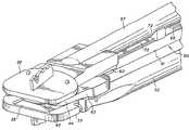
- FIG. 3is a perspective view of a partially assembled insertion instrument of the present invention.
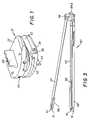
- FIG. 4is a perspective view of a fork distractor of the present invention.
- FIG. 5is a perspective view of the lower arms engaging the lower part of an intervertebral disc implant.
- FIG. 6is a perspective view of the upper arm engaging the upper part of the intervertebral disc implant.
- FIG. 7is an enlarged front view of the body of the fork distractor of the present invention.
- FIG. 8is a side elevational view of an insertion instrument of the present invention engaged with the upper and lower parts of an intervertebral disc implant after insertion of the upper and lower parts of the implant into an intervertebral space.
- FIG. 9is a front, top and side perspective view of an insertion instrument of the present invention creating an introduction space for the pivot element of an intervertebral disc implant.
- FIG. 10is a side elevational view of the introduction space created by the insertion instrument.
- FIG. 11a bottom view of the upper part and associated fork arms in the position depicted in FIG. 10 .
- FIG. 12is a side elevational view of a modified fork distractor of the present invention supporting the upper part of an intervertebral disc implant as the pivot element is being inserted into the space between the upper and lower parts.
- FIG. 13Ais a perspective view of modified forked arm in accordance with the present invention and FIG. 13B is a perspective view of the forked arms shown in FIG. 12 .
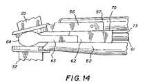
- FIG. 14is a side elevational view of an alternative fork distractor of the present invention where the fork arms are supporting both the upper part and lower part as the pivot element is being inserted therebetween.
- embodiments of the present inventionare directed to instruments and methods for inserting artificial intervertebral disc implants 21 or the like.
- the intervertebral spacePrior to inserting of an intervertebral disc implant 21 , the intervertebral space must be cleaned out with instruments such as elevators and/or chisels.
- the next stepis to determine the precise size of an inlay protrusion 44 of a pivot element 42 (which is located between an upper part 22 and a lower part 32 of implant 21 ) which provides a correct overall height for disc implant 21 for that particular (height) intervertebral space. This determination is accomplished by providing a set of trial implants of different sizes. The operator thus selects by experience the trial implant that the operator believes would be the most appropriate for that particular intervertebral space and disc implant 21 selected.
- the next stepis to form the cutouts in the adjacent vertebrae using the trial implant.
- These cutoutsare designed to receive raised keels of the upper and lower plates.
- a chiselis used to form the required cutouts in the opposed vertebrae.
- an insertion instrument 50 disclosed hereafteris then used to insert intervertebral implant 21 into the intervertebral space defined by the two vertebrae as explained in detail below.
- intervertebral disc implants 21used in connection with the present invention will include those similar to disc implant 21 depicted in detail in FIGS. 1-2 .
- FIGS. 1-2show disc implant 21 having upper part 22 with a raised keel 23 protruding therefrom, and lower part 32 with a raised keel 33 protruding therefrom. Also shown are upper insertion apertures 24 and one of two lower apertures 34 .
- Pivot element 42is shown in place between upper part 22 and lower part 32 in FIGS. 1 and 2 , and in a position to be inserted into the holding space of the lower part 32 in FIG. 2 .
- Upper part 22(as shown in FIGS. 10 and 11 ) has a domed-shaped concave bearing face 26 which receives a mating convex inlay protrusion 44 of pivot element 42 .
- Pivot element 42shown best in FIG. 2 , will typically have a substantially rectangular base 43 which is to be captured in a recess 35 of lower part 32 and protrusion 44 which is to be received in concave domed-shaped bearing face 26 of upper part 22 .
- Lower part 32shown best in FIG. 2 , comprises a recess 35 to snugly receive rectangular base 43 of pivot element 42 .
- Pivot element 42can be inserted into recess 35 from the open side as shown in FIG. 2 , allowing opposite edges 45 of base 43 to engage lateral grooves 37 in lower part 32 so that pivot element 42 can be inserted and then moved forwardly along grooves 37 into a fully inserted/captured position in recess 35 .
- Other details of implant 21are disclosed in WO 01/01893 as noted above and thus need not be discussed here further.
- inlay protrusion 44engages concave bearing face 26 of upper part 22 , so that upper part 22 and lower part 32 are braced on one another via pivot element 42 and have a pivotal relationship one to the other.
- Both upper part 22 and lower part 32 on a front or anterior face thereofhave insertion apertures 24 , 34 which are designed to receive mounting pins 51 of the insertion instrument of the present invention as described below.
- FIG. 1clearly shows upper part 22 and lower part 32 with pivot element 42 positioned therebetween so that relative pivoting of upper part 22 and lower part 32 is permitted.
- insertion instrument 50 of the present inventionhas an elongated upper arm 57 and substantially parallel elongated lower arms 52 , 53 .
- Upper arm 57 and lower arms 52 , 53engage a mounting structure 54 , which holds the adjacent ends of arms 52 , 53 and 57 as noted below.
- the second or free ends of lower arms 52 , 53are each engageable in lower part 32 of disc implant 21 while the second or free end of upper arm 57 is engageable in upper part 22 . Referring to FIG. 3 , these engagements are accomplished by retaining pins 51 on the associated ends of each arm 52 , 53 , 57 .
- a holder 56is used to attach pins 51 to upper arm 57 as broadly described in WO 01/19295, by which upper part 22 is engaged with upper arm 57 at a predetermined slight angle to vertical as shown.
- Mounting structure 54includes an opening 54 A with a spring-loaded ball catch (not shown) therein which receives mounting portion 66 A of a part of the casing 66 (see FIG. 4 ) to secure the distractor, as discussed in detail below.
- lower arms 52 , 53are rotatable about their central, longitudinal axes in order to lock lower arms 52 , 53 to lower part 32 as shown and described in WO 01/19295 and as described below with respect to FIG. 5 .
- upper arm 57has pins 51 of holder 56 slidably received in apertures 24 of upper part 22 as shown in FIG. 6 .
- holder 56is rigid with upper arm 57 and hence does not pivot relative to upper arm 57 as does the holder disclosed in WO 01/19295.
- mounting structure 54holds arms 52 , 53 , 57 in pivotable relationship with one another, with lower arms 52 , 53 parallel to one another and with upper arm 57 at a small angle to the plane of lower arms 52 , 53 .
- mounting structure 54is spaced apart from the plane defined by the two lower arms 52 and 53 .
- Upper arm 57is vertically disposed approximately midway between the two lower arms 52 and 53 , so that the free or forward end of upper arm 57 can, in its lowered position, enter the space between the two parallel lower arms 52 and 53 .
- upper arm 57is circular in cross section and on its free end carries U-shaped holder 56 which receives the free end of upper arm 57 .
- Holder 56 and upper arm 57are immovably joined together as noted above.
- Instrument 50 of the present inventionfurther comprises a distractor 60 , as shown best in FIG. 4 , which comprises an elongated arm 61 with a body 62 securely attached thereto. At a forward end of body 62 there are a pair of fork-shaped arms 63 that extend forward beyond body 62 substantially parallel to the longitudinal axis of arm 61 . As shown in FIGS. 4 and 7 , body 62 has a solid wedge portion 70 which matingly seats with and engages upper arm 57 as wedge portion 70 approaches the free end of upper arm 57 . In addition, as best shown in FIG. 7 , fork arms 63 also have rounded lower seats 71 which similarly engage the adjacent portions of lower arms 52 and 53 .
- distractor 60is usable with instruments 50 having differently spaced lower arms 53 .
- the outside portion of seats 71are designed to mate against lower arms 53 (only one of which is partially shown in phantom) where instrument 50 has widely spaced lower arms 53 (for larger sized implants 21 ); while the inside portion of seats 71 are similarly designed to mate against lower arms 53 ′ (only one of which is partially shown in phantom) where instrument 50 has more closely spaced lower arms 53 ′ (for smaller sized implants 21 ). If only one spacing of lower arms 50 is usable, then seats 71 can be designed to mate over the entire surface thereof with the associated lower arm 53 .
- wedge portion 70As wedge portion 70 moves forward along arms 52 , 53 and 57 and approaches disc implant 21 , wedge portion 70 forces upper arm 57 slowly away from lower arms 52 , 53 , creating a small starting space between upper part 22 and lower part 32 . It will thus be appreciated that wedge portion 70 serves a function similar to the spreader element ( 43 ) disclosed in WO 01/19295. It will also be appreciated that body 62 includes a protrusion 74 which also serves a function similar to protrusion 44 disclosed in WO 01/19295.
- protrusion 74is used to initially push rectangular base 43 of pivot element 42 —whose edges 45 engage longitudinal grooves 55 provided along opposing (facing) inner sides of lower arms 52 , 53 —forward to a position immediately adjacent implant 21 and then partially into recess 35 .
- the final forward movement of pivot element 42is then accomplished using a pushing element 80 (see FIG. 10 ) similar to that described in WO 01/19295, which also engages rectangular base 43 so that no potentially damaging contact is made with inlay protrusion 44 .
- distractor 60 of the present inventionmay further include a leaf spring 73 provided behind wedge portion 70 which resiliently mounts a seat 72 .
- a leaf spring 73provided behind wedge portion 70 which resiliently mounts a seat 72 .
- seat 72This movement of seat 72 is made against the mild force of leaf spring 73 , so that only a minor reactive force is exerted on arms 52 , 53 and 57 which is insufficient to force upper part 22 and lower part 32 of disc implant 21 apart (so that no significant separating forces are conveyed to upper part 22 and lower part 32 ). It will be appreciated that seat 72 does not actually contact arm 61 during this movement, since wedge portion 70 is slightly higher than the thickness of seat 72 so that wedge portion 70 takes over the holding function of seat 72 when fork arms 63 approach implant 21 —and turns this holding function additionally to a separating function as noted below.
- Distractor 60engages upper arm 57 and lower arms 52 , 53 in such a way that as distractor 60 slides forward along between lower arms 52 , 53 it rides along the top of lower arms 52 , 53 and first seat 72 of leaf spring 73 engages upper arm 57 and then wedge portion 70 engages upper arm 57 .
- FIG. 8shows the position of the upper and lower parts 22 , 32 nested together (as described in WO 01/19295) in their closed or initial position before wedge portion 70 (not shown in this Figure) engages upper arm 57 and lower arms 52 , 53 .
- distractor 60With the parts in this position, distractor 60 , as it moves further forward along upper arm 57 and lower arms 52 , 53 towards disc implant 21 , will slightly separate upper and lower parts 22 , 32 from each other (and hence slightly enlarge the intervertebral space), as wedge portion 70 of distractor 60 urges upper arm 57 upwardly slightly, creating a starting space.
- This starting spaceis relatively easy to create, as the intervertebral forces holding upper part 22 and lower part 32 adjacent one another are initially small.
- pivot element 42has caused pivot element 42 to be located immediately adjacent recess 35 and thus ready to be pushed forward into recess 35 as fork arms 63 move forward between upper part 22 and lower part 32 and wedge portion 70 and/or fork arms 63 open a space sufficient for receiving pivot element 42 to pass into (as discussed below).
- wedge portion 70may be sufficient by itself to perform all or most of the needed distracting movement.
- heads 64 of fork arms 63may provide no or only a minor effective distracting force. It will be appreciated that where fork arms 63 provide essentially no distracting force, heads 64 of fork arms 63 nonetheless will engage along upper part 22 and provide a holding or supporting force along upper part 22 to maintain upper part 22 in the proper orientation with lower part 32 (and hence to prevent falling or pivoting of upper part 22 ).
- heads 64 of fork arms 63provide only a minor distracting force (which distracting force also serves to support or hold), this distracting force of heads 64 of fork arms 63 will primarily be exerted as heads 64 of fork arms 63 engage along upper part 22 as wedge portion 70 does not provide the complete distracting force necessary.
- heads 64 of fork arms 63only begin to contact upper part 22 after passing some of the anterior portion thereof; but this supporting/holding/forcing could occur starting at the anterior portion, but more likely will occur starting near the posterior portion of upper part 22 at the end of the forward movement of distractor 60 .
- heads 64 of fork arms 63can begin providing only a supporting/holding force and then provide some distracting force, or vice versa or alternately, as forward movement of distractor 60 occurs.
- heads 64 of fork arms 63may perform all or most of the distracting movement after the initial starting space at the anterior end of upper part 22 is created by wedge portion 70 .
- wedge portion 70may provide no or only a minor additional effective distracting force. It will be appreciated that where wedge portion 70 provides essentially no additional distracting force, wedge portion 70 may or will nonetheless provide a holding or supporting force at the anterior part of upper part 22 to help maintain upper part 22 in the proper orientation with lower part 32 (and hence to prevent falling or pivoting of upper part 22 ).
- wedge portion 70provides only a minor additional distracting force (which distracting force also serves to support or hold), this distracting force of wedge portion 70 will primarily be exerted at the anterior portion of upper part 22 to which upper arm 57 is directly attached.
- wedge portion 70only effects a supporting/holding and/or distracting force on the anterior part of upper part 22 as heads 64 of fork arms 63 travel further along the posterior half thereof; but this supporting/holding/forcing could occur starting at the beginning of the forward engaging movement of heads 64 , but more likely will occur starting near the end of the forward movement of heads 64 (the end of the forward movement of distractor 60 ).
- wedge portion 70can begin providing only a supporting/holding force and then provide some distracting force, or vice versa or alternately, as the forward movement of distractor 60 occurs.
- wedge portion 70 and heads 64will be designed so that in many or even most situations it will be some, possibly changing, combination of the distracting forces of both heads 64 of fork arms 63 and wedge portion 70 which will effect the distracting movement of upper part 22 away from lower part 32 .
- wedge portion 70will do more of the separating while heads 64 act more as a support; while where the separation space is less easily produced (a larger separating force is needed), heads 64 will do more of the separating (and supporting) while wedge portion 70 does less.
- heads 64 of fork arms 63acts between lower arms 52 , 53 on which body 62 rests and the engaging portions of heads 64 of fork arms 63 on the lower/inner surface of upper part 22 as shown in FIGS. 10-12 .
- the reactive force of heads 64 of the fork arms 63is on the surface of upper part 22 , this force acts directly to hold/force upper part 22 away from lower part 32 .
- the reactive force of heads 64 of fork arms 63does begin at the anterior end of the facing/inner surface of upper part 22 , this force moves forward along this surface with only a small distracting force until heads 64 are moved substantially inward (forward) to the posterior portion as shown in FIGS. 10 and 12 .
- the distracting force of heads 64begin at about the midway point between the anterior and posterior ends of the surfaces. In this way, there is a more forceful pivoting torque exerted by heads 64 of fork arms 63 on the surface of upper part 22 as fork arms 63 advance further (as the moment arm length increases, as the moment arm length is measured from the forward end of U-shaped holder 56 ). This is advantageous since generally it is desired to have more separating torque or force at the posterior end of upper part 22 where a greater resistance to separation is expected.
- arm 61 of distractor 60has a stop pin 75 ( FIG. 4 ) which engages a casing 66 to signify when distractor 61 is fully inserted.
- pin 75is thus specifically positioned on arm 61 to engage casing 66 at the point where heads 64 of fork arms 63 have advanced fully or forwards sufficiently into the space between upper part 22 and lower part 32 to provide the needed spacing for the completion of the insertion of pivot element 42 (and clearance for inlay protrusion 44 ) by the action of pushing element 80 ( FIG. 10 ).
- heads 64 of fork arms 63are at a maximum distance from the anterior end of upper part 22 so that a maximum pivoting torque can be exerted by heads 64 (as noted above, where the moment arm is greatest) in case the forces resisting distraction are at their highest (at the maximum displacement of upper part 22 and lower part 32 , which is the maximum vertebral spacing).
- FIG. 11clearly shows the relationship between distractor 60 and, as shown in the drawing, the lower/inner surface of upper part 22 , wherein fork arms 63 flank domed-shaped bearing face 26 .
- This positioningallows pivot element 42 (not shown in FIG. 11 ) to be pushed partially into position in recess 35 as heads 64 of fork arms 63 are moved forward to support upper part 22 in the raised position (where pusher element 80 , without interference with distractor 60 , then completes pushing pivot element 42 into recess 35 as previously noted).
- FIGS. 13A and 13Bshow different bodies 62 B and 62 C with protrusions 74 B and 74 C and fork arms 63 B and 63 C that may be used in connection with distractor 60 of the present invention.
- the different vertical thicknesses or heights of heads 64 B and 64 C of respective fork arms 63 B and 63 Cprovide for the creation of different height insertion spaces between upper part 22 and lower part 32 , which would correspond to the different available heights of protrusions 44 ( FIG. 2 ) typically provided in a set of pivot elements 42 .
- wedge portions 70 B and 70 Care respectively vertically thicker or higher in correspondence with the increased thickness of heads 64 B and 64 C of fork arms 63 B and 63 C.
- This corresponding thicknessis needed to maintain the proper orientation of upper part 22 to lower part 32 during use of distractor 60 .
- the heights of heads 64 B and 64 Ccould be lowered or raised to effect lesser or greater holding/distracting forces by heads 64 B and 64 C relative to wedge portions 70 B and 70 C; and similarly but probably less preferably, the heights of wedge portions 70 B and 70 C could be lowered or raised to effect lesser or greater holding/distracting forces by wedge portions 70 B and 70 C relative to heads 64 B and 64 C.
- distractor 60secures distractor 60 to mounting structure 54 via opening 54 A and the ball catch therein in the much the same manner as the distractor is attached in WO 01/19295.
- distractor 60further comprises a hex end 67 which extends rotatably through casing 66 and beyond mounting portion 66 A and which is designed to be engaged by a suitable wrench having a mating hex socket or the like (not shown) if desired.
- a suitable wrenchhaving a mating hex socket or the like (not shown) if desired.
- the opposite end from hex end 67is provided with a square end or the like (not shown) to which is securely mounted a thumbscrew 69 .
- thumbscrew 69 or hex end 67results in the turning of a gear wheel (not shown, but inside casing 66 ) which engages a tooth rack 65 on elongated arm 61 .
- This systemmay be used to carefully and precisely advance distractor 60 longitudinally Forward towards the second ends of arms 52 , 53 and 57 as noted above and in much the same manner as the distractor is advanced in WO 01/19295—except that a more positive and forceful insertion force can be exerted on tooth rack 65 by the use of the wrench if such insertion force is needed.
- portion 66 Asecures distractor 60 to mounting structure 54 via opening 54 A and the ball catch therein in the much the same manner as the distractor is attached in WO 01/19295.
- distractor 60further comprises a hex end 67 which extends rotatably through casing 66 and beyond mounting portion 66 A and which is designed to be engaged by a suitable wrench having a mating hex socket or the like (not shown) if desired.
- the opposite end from hex end 67is provided with a square end or the like (not shown) to which is securely mounted a thumbscrew 69 .
- Turning of either thumbscrew 69 or hex end 67results in the turning of a gear wheel (not shown, but inside casing 66 ) which engages a tooth rack 65 on elongated arm 61 .
- This systemmay be used to carefully and precisely advance distractor 60 longitudinally Forward towards the second ends of arms 52 , 53 and 57 as noted above and in much the same manner as the distractor is advanced in WO 01/19295—except that a more positive and forceful insertion force can be exerted on tooth rack 65 by the use of the wrench if such insertion force is needed.
- the insertion instrument described hereincomprises a biocompatible metal, such as titanium or a titanium alloy or a stainless steel composite; and may be the same or different material as the upper and lower parts.
- Pivot element 42is also made from a biocompatible material, and is preferably a biocompatible plastic material such as polyethylene.
- distractor 60may comprise a biocompatible coating that assists sliding relative to the arms, or distractor 60 may comprise a plastic material for the same reason.
- upper part 22 and lower part 32are engaged with upper arm 57 and lower arms 52 , 53 as shown in FIGS. 5 and 6 .
- Lower part 32is locked to lower arms 52 , 53 by rotation thereof, which causes locking bar protrusions 58 to engage recesses 36 of lower part 32 .
- Upper and lower parts 22 , 32are then brought to their closest proximity, preferably nested together (as no pivot element is yet present), and inserted into the intervertebral space as shown in FIG. 8 .
- pivot element 42After insertion of upper and lower parts 22 , 32 forwardly into the intervertebral space, pivot element 42 is inserted between lower arms 52 adjacent the rear thereof. After mounting of distractor 60 , pivot element 42 is then moved forward towards the intervertebral space by distractor 60 with edges 45 thereof engaging grooves 55 formed in lower arms 52 , 53 as described in WO 01/19295. As shown in FIGS. 9 , 10 and 12 , once the starting space is created, further forward advancement of wedge portion 70 causes heads 64 of fork arms 63 to engage the bottom/inner surface of upper part 22 as noted in detail above, pushing and/or holding upper part 22 away from lower part 32 which is held in place by lower arms 52 , 53 .
- heads 64 of fork arms 63have been described above as only engaging the lower/inner surface of upper part 22 as fork arms 63 advance into the intervertebral space provided between upper part 22 and lower part 32 , it will be appreciated that engagement of the upper surface of lower part 32 would be possible as shown in FIG. 14 .
- a more positive separation of upper part 22 from lower part 32 using heads 64would be achieved as the separating force would be directly exerted between the facing surfaces of lower part 32 and upper part 22 by heads 64 of fork arms 63 once heads 64 of fork arms 63 completely entered the space provided between upper part 22 and lower part 32 .
- the holding forces of arms 52 , 53 and 57 on upper part 22 and lower part 32 in this embodimentwould thus not need to be as secure.
Landscapes
- Health & Medical Sciences (AREA)
- Orthopedic Medicine & Surgery (AREA)
- Life Sciences & Earth Sciences (AREA)
- Engineering & Computer Science (AREA)
- Biomedical Technology (AREA)
- Animal Behavior & Ethology (AREA)
- Surgery (AREA)
- Veterinary Medicine (AREA)
- Public Health (AREA)
- General Health & Medical Sciences (AREA)
- Heart & Thoracic Surgery (AREA)
- Transplantation (AREA)
- Vascular Medicine (AREA)
- Oral & Maxillofacial Surgery (AREA)
- Cardiology (AREA)
- Nuclear Medicine, Radiotherapy & Molecular Imaging (AREA)
- Neurology (AREA)
- Medical Informatics (AREA)
- Molecular Biology (AREA)
- Physical Education & Sports Medicine (AREA)
- Prostheses (AREA)
Abstract
Description
Claims (34)
Priority Applications (12)
| Application Number | Priority Date | Filing Date | Title |
|---|---|---|---|
| US10/947,660US7547309B2 (en) | 2004-09-23 | 2004-09-23 | Distractor for lumbar insertion instrument |
| EP11154751.9AEP2329797B1 (en) | 2004-09-23 | 2005-09-16 | Improved distractor for lumbar insertion instrument |
| KR1020077008530AKR20070089126A (en) | 2004-09-23 | 2005-09-16 | Improved stretcher for lumbar insertion device |
| CNA200580032295XACN101035490A (en) | 2004-09-23 | 2005-09-16 | Improved destractor for lumbar insertion instrument |
| AT05797540TATE532483T1 (en) | 2004-09-23 | 2005-09-16 | IMPROVED DISTRACTOR FOR A LUMBAR INTRODUCTION INSTRUMENT |
| TW094131945ATW200621210A (en) | 2004-09-23 | 2005-09-16 | Improved distractor for lumbar insertion instrument |
| EP05797540AEP1793768B1 (en) | 2004-09-23 | 2005-09-16 | Improved distractor for lumbar insertion instrument |
| CA002581825ACA2581825A1 (en) | 2004-09-23 | 2005-09-16 | Improved distractor for lumbar insertion instrument |
| BRPI0515895-8ABRPI0515895A (en) | 2004-09-23 | 2005-09-16 | insertion instrument for inserting an intervertebral implant, and combination of instrument and method for inserting an intervertebral implant into an intervertebral space |
| JP2007532471AJP2008513122A (en) | 2004-09-23 | 2005-09-16 | Improved lumbar insertion instrument distractor |
| AU2005289892AAU2005289892A1 (en) | 2004-09-23 | 2005-09-16 | Improved distractor for lumbar insertion instrument |
| PCT/US2005/033006WO2006036579A2 (en) | 2004-09-23 | 2005-09-16 | Improved distractor for lumbar insertion instrument |
Applications Claiming Priority (1)
| Application Number | Priority Date | Filing Date | Title |
|---|---|---|---|
| US10/947,660US7547309B2 (en) | 2004-09-23 | 2004-09-23 | Distractor for lumbar insertion instrument |
Publications (2)
| Publication Number | Publication Date |
|---|---|
| US20060064107A1 US20060064107A1 (en) | 2006-03-23 |
| US7547309B2true US7547309B2 (en) | 2009-06-16 |
Family
ID=36075058
Family Applications (1)
| Application Number | Title | Priority Date | Filing Date |
|---|---|---|---|
| US10/947,660Active2026-03-08US7547309B2 (en) | 2004-09-23 | 2004-09-23 | Distractor for lumbar insertion instrument |
Country Status (11)
| Country | Link |
|---|---|
| US (1) | US7547309B2 (en) |
| EP (2) | EP1793768B1 (en) |
| JP (1) | JP2008513122A (en) |
| KR (1) | KR20070089126A (en) |
| CN (1) | CN101035490A (en) |
| AT (1) | ATE532483T1 (en) |
| AU (1) | AU2005289892A1 (en) |
| BR (1) | BRPI0515895A (en) |
| CA (1) | CA2581825A1 (en) |
| TW (1) | TW200621210A (en) |
| WO (1) | WO2006036579A2 (en) |
Cited By (31)
| Publication number | Priority date | Publication date | Assignee | Title |
|---|---|---|---|---|
| US20050021042A1 (en)* | 2003-07-21 | 2005-01-27 | Theirry Marnay | Instruments and method for inserting an intervertebral implant |
| US20050273173A1 (en)* | 2003-08-05 | 2005-12-08 | Gordon Charles R | Expandable articulating intervertebral implant with cam |
| US20070016221A1 (en)* | 1999-09-14 | 2007-01-18 | Boris Beyersdorff | Insertion instrument for an intervertebral implant |
| US20070208346A1 (en)* | 2003-04-28 | 2007-09-06 | Theirry Marnay | Instruments and method for preparing an intervertebral space for receiving an artificial disc implant |
| US20070209222A1 (en)* | 2004-09-08 | 2007-09-13 | Kay Fischer | Surgical instrument |
| US20080172129A1 (en)* | 2003-08-01 | 2008-07-17 | Spinal Kinetics, Inc. | Method for Implanting Prosthetic Intervertebral Discs in a Spine |
| US20080234684A1 (en)* | 2007-02-08 | 2008-09-25 | Warsaw Orthopedic, Inc. | Instruments and techniques for guiding instruments to a spinal column |
| US20100168860A1 (en)* | 2008-12-22 | 2010-07-01 | Marc Reichen | Orthopedic implant with flexible keel |
| US7785351B2 (en) | 2003-08-05 | 2010-08-31 | Flexuspine, Inc. | Artificial functional spinal implant unit system and method for use |
| US20110054548A1 (en)* | 2009-09-03 | 2011-03-03 | Zimmer Spine, Inc. | Spinal implant delivery methods and devices |
| US7909869B2 (en) | 2003-08-05 | 2011-03-22 | Flexuspine, Inc. | Artificial spinal unit assemblies |
| US7959677B2 (en) | 2007-01-19 | 2011-06-14 | Flexuspine, Inc. | Artificial functional spinal unit system and method for use |
| US8105381B2 (en) | 2002-12-13 | 2012-01-31 | Spine Solutions, Inc. | Intervertebral implant, insertion tool and method of inserting same |
| US8118869B2 (en) | 2006-03-08 | 2012-02-21 | Flexuspine, Inc. | Dynamic interbody device |
| US8157844B2 (en) | 2007-10-22 | 2012-04-17 | Flexuspine, Inc. | Dampener system for a posterior stabilization system with a variable length elongated member |
| US8162994B2 (en) | 2007-10-22 | 2012-04-24 | Flexuspine, Inc. | Posterior stabilization system with isolated, dual dampener systems |
| US8182514B2 (en) | 2007-10-22 | 2012-05-22 | Flexuspine, Inc. | Dampener system for a posterior stabilization system with a fixed length elongated member |
| US8187330B2 (en) | 2007-10-22 | 2012-05-29 | Flexuspine, Inc. | Dampener system for a posterior stabilization system with a variable length elongated member |
| US8267965B2 (en) | 2007-10-22 | 2012-09-18 | Flexuspine, Inc. | Spinal stabilization systems with dynamic interbody devices |
| US20120310293A1 (en)* | 2008-10-16 | 2012-12-06 | Aesculap Implant Systems, Llc. | Surgical instrument and method of use for inserting an implant between two bones |
| US8337500B2 (en) | 2006-07-31 | 2012-12-25 | Synthes Usa, Llc | Drilling/milling guide and keel cut preparation system |
| US8500749B2 (en)* | 2011-04-19 | 2013-08-06 | Prescient Surgical Designs, Llc | Apparatus and method for inserting intervertebral implants |
| US8506634B2 (en) | 1999-07-02 | 2013-08-13 | DePuy Synthes Products, LLC | Intervertebral implant |
| US8523912B2 (en) | 2007-10-22 | 2013-09-03 | Flexuspine, Inc. | Posterior stabilization systems with shared, dual dampener systems |
| US8940051B2 (en) | 2011-03-25 | 2015-01-27 | Flexuspine, Inc. | Interbody device insertion systems and methods |
| US8998990B2 (en) | 2006-07-24 | 2015-04-07 | DePuy Synthes Products, LLC | Intervertebral implant with keel |
| US9034046B2 (en) | 2007-10-30 | 2015-05-19 | Aesculap Implant Systems, Llc | Vertebral body replacement device and method for use to maintain a space between two vertebral bodies within a spine |
| US9492288B2 (en) | 2013-02-20 | 2016-11-15 | Flexuspine, Inc. | Expandable fusion device for positioning between adjacent vertebral bodies |
| US9517144B2 (en) | 2014-04-24 | 2016-12-13 | Exactech, Inc. | Limited profile intervertebral implant with incorporated fastening mechanism |
| US9526627B2 (en) | 2011-11-17 | 2016-12-27 | Exactech, Inc. | Expandable interbody device system and method |
| US10398565B2 (en) | 2014-04-24 | 2019-09-03 | Choice Spine, Llc | Limited profile intervertebral implant with incorporated fastening and locking mechanism |
Families Citing this family (41)
| Publication number | Priority date | Publication date | Assignee | Title |
|---|---|---|---|---|
| US7169182B2 (en) | 2001-07-16 | 2007-01-30 | Spinecore, Inc. | Implanting an artificial intervertebral disc |
| US7223291B2 (en)* | 2001-07-16 | 2007-05-29 | Spinecore, Inc. | Intervertebral spacer device having engagement hole pairs for manipulation using a surgical tool |
| US6989032B2 (en)* | 2001-07-16 | 2006-01-24 | Spinecore, Inc. | Artificial intervertebral disc |
| US8858564B2 (en)* | 2001-02-15 | 2014-10-14 | Spinecore, Inc. | Wedge plate inserter/impactor and related methods for use in implanting an artificial intervertebral disc |
| US6673113B2 (en) | 2001-10-18 | 2004-01-06 | Spinecore, Inc. | Intervertebral spacer device having arch shaped spring elements |
| US8940047B2 (en) | 2001-02-15 | 2015-01-27 | Spinecore, Inc. | Intervertebral spacer device having recessed notch pairs for manipulation using a surgical tool |
| US7771477B2 (en) | 2001-10-01 | 2010-08-10 | Spinecore, Inc. | Intervertebral spacer device utilizing a belleville washer having radially spaced concentric grooves |
| US7713302B2 (en)* | 2001-10-01 | 2010-05-11 | Spinecore, Inc. | Intervertebral spacer device utilizing a spirally slotted belleville washer having radially spaced concentric grooves |
| EP1647244A1 (en)* | 2004-10-15 | 2006-04-19 | Zimmer GmbH | System of instruments for the insertion of intervertebral disc implants |
| US8128662B2 (en) | 2004-10-20 | 2012-03-06 | Vertiflex, Inc. | Minimally invasive tooling for delivery of interspinous spacer |
| US8152837B2 (en) | 2004-10-20 | 2012-04-10 | The Board Of Trustees Of The Leland Stanford Junior University | Systems and methods for posterior dynamic stabilization of the spine |
| US8167944B2 (en) | 2004-10-20 | 2012-05-01 | The Board Of Trustees Of The Leland Stanford Junior University | Systems and methods for posterior dynamic stabilization of the spine |
| US8317864B2 (en) | 2004-10-20 | 2012-11-27 | The Board Of Trustees Of The Leland Stanford Junior University | Systems and methods for posterior dynamic stabilization of the spine |
| US8273108B2 (en) | 2004-10-20 | 2012-09-25 | Vertiflex, Inc. | Interspinous spacer |
| US9119680B2 (en) | 2004-10-20 | 2015-09-01 | Vertiflex, Inc. | Interspinous spacer |
| US7618459B2 (en)* | 2005-09-26 | 2009-11-17 | Infinity Orthopedics Ltd. | Universal spinal disc implant system |
| US8034113B2 (en)* | 2005-09-27 | 2011-10-11 | Randall Lane Acker | Joint prosthesis and method of implanting same |
| CN101442962A (en)* | 2006-05-11 | 2009-05-27 | 康隆有限公司 | Implanting a tissue prosthesis |
| US9381098B2 (en)* | 2006-09-28 | 2016-07-05 | Spinal Kinetics, Inc. | Tool systems for implanting prosthetic intervertebral discs |
| FR2908978B1 (en)* | 2006-11-28 | 2012-08-03 | Spineart Sa | PROSTHESES HOLDER AND THEIR APPLICATIONS. |
| AU2008241447B2 (en) | 2007-04-16 | 2014-03-27 | Vertiflex, Inc. | Interspinous spacer |
| US20080262494A1 (en)* | 2007-04-17 | 2008-10-23 | Warsaw Orthopedic, Inc. | Spinal tool |
| US8579910B2 (en) | 2007-05-18 | 2013-11-12 | DePuy Synthes Products, LLC | Insertion blade assembly and method of use |
| US8480715B2 (en)* | 2007-05-22 | 2013-07-09 | Zimmer Spine, Inc. | Spinal implant system and method |
| AU2009206098B2 (en) | 2008-01-15 | 2014-10-30 | Vertiflex, Inc. | Interspinous spacer |
| US8449554B2 (en) | 2008-03-07 | 2013-05-28 | K2M, Inc. | Intervertebral implant and instrument with removable section |
| DE102008050233A1 (en)* | 2008-10-02 | 2010-04-08 | Copf jun., Franz, Dr. | Instrument for measuring the distraction pressure between vertebral bodies |
| CN101991457B (en)* | 2009-08-27 | 2012-12-19 | 邹德威 | Interfacial distracting device of cervical vertebra facet joint |
| US9180017B2 (en)* | 2009-10-13 | 2015-11-10 | Nicholas Poulos | Lumbar implant |
| US8277509B2 (en)* | 2009-12-07 | 2012-10-02 | Globus Medical, Inc. | Transforaminal prosthetic spinal disc apparatus |
| US9358122B2 (en) | 2011-01-07 | 2016-06-07 | K2M, Inc. | Interbody spacer |
| US9265620B2 (en) | 2011-03-18 | 2016-02-23 | Raed M. Ali, M.D., Inc. | Devices and methods for transpedicular stabilization of the spine |
| EP2685921B1 (en) | 2011-03-18 | 2019-03-13 | Raed M. Ali, M.D., Inc. | Transpedicular access to intervertebral spaces and related spinal fusion systems and methods |
| US10687962B2 (en) | 2013-03-14 | 2020-06-23 | Raed M. Ali, M.D., Inc. | Interbody fusion devices, systems and methods |
| US9861495B2 (en) | 2013-03-14 | 2018-01-09 | Raed M. Ali, M.D., Inc. | Lateral interbody fusion devices, systems and methods |
| US11219536B2 (en)* | 2019-05-01 | 2022-01-11 | Simplify Medical Pty Ltd | Intervertebral prosethetic disc placement and removal systems |
| GB201910640D0 (en) | 2019-07-25 | 2019-09-11 | Axis Spine Tech Ltd | Insertions instruments |
| WO2023285675A1 (en) | 2021-07-16 | 2023-01-19 | Blue Ocean Spine Gmbh | Adjustable intervertebral cage, associated instrument and manufacturing process therefor |
| WO2023158581A1 (en) | 2022-02-15 | 2023-08-24 | Boston Scientific Neuromodulation Corporation | Interspinous spacer and systems utilizing the interspinous spacer |
| US12433646B2 (en) | 2023-02-21 | 2025-10-07 | Boston Scientific Neuromodulation Corporation | Interspinous spacer with actuator locking arrangements and methods and systems |
| US12390340B2 (en) | 2023-03-15 | 2025-08-19 | Boston Scientific Neuromodulation Corporation | Interspinous spacer with a range of deployment positions and methods and systems |
Citations (21)
| Publication number | Priority date | Publication date | Assignee | Title |
|---|---|---|---|---|
| US5314477A (en) | 1990-03-07 | 1994-05-24 | J.B.S. Limited Company | Prosthesis for intervertebral discs and instruments for implanting it |
| US5431658A (en)* | 1994-02-14 | 1995-07-11 | Moskovich; Ronald | Facilitator for vertebrae grafts and prostheses |
| US5571109A (en) | 1993-08-26 | 1996-11-05 | Man Ceramics Gmbh | System for the immobilization of vertebrae |
| US6159215A (en) | 1997-12-19 | 2000-12-12 | Depuy Acromed, Inc. | Insertion instruments and method for delivering a vertebral body spacer |
| WO2001001893A1 (en) | 1999-07-02 | 2001-01-11 | Spine Solutions Inc. | Intervertebral implant |
| WO2001019295A1 (en) | 1999-09-14 | 2001-03-22 | Spine Solutions Inc. | Instrument for inserting intervertebral implants |
| US6224599B1 (en) | 1999-05-19 | 2001-05-01 | Matthew G. Baynham | Viewable wedge distractor device |
| US6478800B1 (en) | 2000-05-08 | 2002-11-12 | Depuy Acromed, Inc. | Medical installation tool |
| US20030069586A1 (en) | 2001-07-16 | 2003-04-10 | Errico Joseph P. | Instrumentation and methods for use in implanting an artificial intervertebral disc |
| US6565574B2 (en) | 1999-01-25 | 2003-05-20 | Gary K. Michelson | Distractor for use in spinal surgery |
| US6599294B2 (en)* | 1999-01-30 | 2003-07-29 | Aesculap Ag & Co. Kg | Surgical instrument for introducing intervertebral implants |
| US6610065B1 (en) | 1998-10-28 | 2003-08-26 | Sdgi Holdings, Inc. | Interbody fusion implants and instrumentation |
| US6652533B2 (en)* | 2001-09-20 | 2003-11-25 | Depuy Acromed, Inc. | Medical inserter tool with slaphammer |
| US20040030387A1 (en)* | 2002-03-11 | 2004-02-12 | Landry Michael E. | Instrumentation and procedure for implanting spinal implant devices |
| US20040143332A1 (en)* | 2002-10-31 | 2004-07-22 | Krueger David J. | Movable disc implant |
| US20040225295A1 (en)* | 2001-07-16 | 2004-11-11 | Rafail Zubok | Wedge ramp distractor and related methods for use in implanting artificial intervertebral discs |
| US20050228500A1 (en)* | 2003-08-01 | 2005-10-13 | Spinal Kinetics, Inc. | Prosthetic intervertebral disc and methods for using same |
| US20060030856A1 (en)* | 2004-07-21 | 2006-02-09 | Sdgi Holding, Inc. | Dual distractor inserter |
| US20060089656A1 (en)* | 2004-10-22 | 2006-04-27 | Sdgi Holdings, Inc. | Revision instruments |
| US20060149273A1 (en)* | 2004-12-06 | 2006-07-06 | Axiomed Spine Corporation | Method and apparatus for replacing a spinal disc |
| US20060241641A1 (en)* | 2005-04-22 | 2006-10-26 | Sdgi Holdings, Inc. | Methods and instrumentation for distraction and insertion of implants in a spinal disc space |
- 2004
- 2004-09-23USUS10/947,660patent/US7547309B2/enactiveActive
- 2005
- 2005-09-16EPEP05797540Apatent/EP1793768B1/ennot_activeExpired - Lifetime
- 2005-09-16CNCNA200580032295XApatent/CN101035490A/enactivePending
- 2005-09-16WOPCT/US2005/033006patent/WO2006036579A2/enactiveApplication Filing
- 2005-09-16BRBRPI0515895-8Apatent/BRPI0515895A/ennot_activeApplication Discontinuation
- 2005-09-16ATAT05797540Tpatent/ATE532483T1/enactive
- 2005-09-16KRKR1020077008530Apatent/KR20070089126A/ennot_activeWithdrawn
- 2005-09-16AUAU2005289892Apatent/AU2005289892A1/ennot_activeAbandoned
- 2005-09-16JPJP2007532471Apatent/JP2008513122A/ennot_activeWithdrawn
- 2005-09-16EPEP11154751.9Apatent/EP2329797B1/ennot_activeExpired - Lifetime
- 2005-09-16TWTW094131945Apatent/TW200621210A/enunknown
- 2005-09-16CACA002581825Apatent/CA2581825A1/ennot_activeAbandoned
Patent Citations (23)
| Publication number | Priority date | Publication date | Assignee | Title |
|---|---|---|---|---|
| US5314477A (en) | 1990-03-07 | 1994-05-24 | J.B.S. Limited Company | Prosthesis for intervertebral discs and instruments for implanting it |
| US5571109A (en) | 1993-08-26 | 1996-11-05 | Man Ceramics Gmbh | System for the immobilization of vertebrae |
| US5431658A (en)* | 1994-02-14 | 1995-07-11 | Moskovich; Ronald | Facilitator for vertebrae grafts and prostheses |
| US6159215A (en) | 1997-12-19 | 2000-12-12 | Depuy Acromed, Inc. | Insertion instruments and method for delivering a vertebral body spacer |
| US6610065B1 (en) | 1998-10-28 | 2003-08-26 | Sdgi Holdings, Inc. | Interbody fusion implants and instrumentation |
| US6565574B2 (en) | 1999-01-25 | 2003-05-20 | Gary K. Michelson | Distractor for use in spinal surgery |
| US6599294B2 (en)* | 1999-01-30 | 2003-07-29 | Aesculap Ag & Co. Kg | Surgical instrument for introducing intervertebral implants |
| US6224599B1 (en) | 1999-05-19 | 2001-05-01 | Matthew G. Baynham | Viewable wedge distractor device |
| WO2001001893A1 (en) | 1999-07-02 | 2001-01-11 | Spine Solutions Inc. | Intervertebral implant |
| WO2001019295A1 (en) | 1999-09-14 | 2001-03-22 | Spine Solutions Inc. | Instrument for inserting intervertebral implants |
| US7118580B1 (en)* | 1999-09-14 | 2006-10-10 | Spine Solutions Inc. | Instrument for inserting intervertebral implants |
| US6478800B1 (en) | 2000-05-08 | 2002-11-12 | Depuy Acromed, Inc. | Medical installation tool |
| US6755841B2 (en)* | 2000-05-08 | 2004-06-29 | Depuy Acromed, Inc. | Medical installation tool |
| US20040225295A1 (en)* | 2001-07-16 | 2004-11-11 | Rafail Zubok | Wedge ramp distractor and related methods for use in implanting artificial intervertebral discs |
| US20030069586A1 (en) | 2001-07-16 | 2003-04-10 | Errico Joseph P. | Instrumentation and methods for use in implanting an artificial intervertebral disc |
| US6652533B2 (en)* | 2001-09-20 | 2003-11-25 | Depuy Acromed, Inc. | Medical inserter tool with slaphammer |
| US20040030387A1 (en)* | 2002-03-11 | 2004-02-12 | Landry Michael E. | Instrumentation and procedure for implanting spinal implant devices |
| US20040143332A1 (en)* | 2002-10-31 | 2004-07-22 | Krueger David J. | Movable disc implant |
| US20050228500A1 (en)* | 2003-08-01 | 2005-10-13 | Spinal Kinetics, Inc. | Prosthetic intervertebral disc and methods for using same |
| US20060030856A1 (en)* | 2004-07-21 | 2006-02-09 | Sdgi Holding, Inc. | Dual distractor inserter |
| US20060089656A1 (en)* | 2004-10-22 | 2006-04-27 | Sdgi Holdings, Inc. | Revision instruments |
| US20060149273A1 (en)* | 2004-12-06 | 2006-07-06 | Axiomed Spine Corporation | Method and apparatus for replacing a spinal disc |
| US20060241641A1 (en)* | 2005-04-22 | 2006-10-26 | Sdgi Holdings, Inc. | Methods and instrumentation for distraction and insertion of implants in a spinal disc space |
Cited By (84)
| Publication number | Priority date | Publication date | Assignee | Title |
|---|---|---|---|---|
| US8974530B2 (en) | 1999-07-02 | 2015-03-10 | DePuy Synthes Products, LLC | Intervertebral implant |
| US8506634B2 (en) | 1999-07-02 | 2013-08-13 | DePuy Synthes Products, LLC | Intervertebral implant |
| US9526624B2 (en) | 1999-07-02 | 2016-12-27 | DePuy Synthes Products, Inc. | Intervertebral implant |
| US8882839B2 (en) | 1999-07-02 | 2014-11-11 | DePuy Synthes Products, LLC | Intervertebral implant |
| US8795371B2 (en) | 1999-07-02 | 2014-08-05 | DePuy Synthes Products, LLC | Intervertebral implant |
| US20070016221A1 (en)* | 1999-09-14 | 2007-01-18 | Boris Beyersdorff | Insertion instrument for an intervertebral implant |
| US8535326B2 (en) | 1999-09-14 | 2013-09-17 | DePuy Synthes Products, LLC | Insertion instrument for an intervertebral implant |
| US8876836B2 (en) | 1999-09-14 | 2014-11-04 | DePuy Synthes Products, LLC | Insertion instrument for an intervertebral implant |
| US8105381B2 (en) | 2002-12-13 | 2012-01-31 | Spine Solutions, Inc. | Intervertebral implant, insertion tool and method of inserting same |
| US9956086B2 (en) | 2002-12-13 | 2018-05-01 | Centinel Spine Llc | Intervertebral implant, insertion tool and method of inserting same |
| US9585763B2 (en) | 2002-12-13 | 2017-03-07 | DePuy Synthes Products, Inc. | Intervertebral implant, insertion tool and method of inserting same |
| US9084682B2 (en) | 2002-12-13 | 2015-07-21 | DePuy Synthes Products, Inc. | Intervertebral implant, insertion tool and method of inserting same |
| US8579978B2 (en) | 2002-12-13 | 2013-11-12 | DePuy Synthes Products, LLC | Intervertebral implant, insertion tool and method of inserting same |
| US20070208346A1 (en)* | 2003-04-28 | 2007-09-06 | Theirry Marnay | Instruments and method for preparing an intervertebral space for receiving an artificial disc implant |
| US8663229B2 (en) | 2003-04-28 | 2014-03-04 | DePuy Synthes Products, LLC | Instruments and method for preparing an intervertebral space for receiving an artificial disc implant |
| US10182831B2 (en) | 2003-04-28 | 2019-01-22 | Centinel Spine Llc | Instruments and method for preparing an intervertebral space for receiving an artificial disc implant |
| US7803162B2 (en) | 2003-07-21 | 2010-09-28 | Spine Solutions, Inc. | Instruments and method for inserting an intervertebral implant |
| US20050021042A1 (en)* | 2003-07-21 | 2005-01-27 | Theirry Marnay | Instruments and method for inserting an intervertebral implant |
| US8349017B2 (en) | 2003-07-21 | 2013-01-08 | Spine Solutions, Inc. | Instruments and method for inserting an intervertebral implant |
| US20080172129A1 (en)* | 2003-08-01 | 2008-07-17 | Spinal Kinetics, Inc. | Method for Implanting Prosthetic Intervertebral Discs in a Spine |
| US8052723B2 (en) | 2003-08-05 | 2011-11-08 | Flexuspine Inc. | Dynamic posterior stabilization systems and methods of use |
| US8172903B2 (en) | 2003-08-05 | 2012-05-08 | Gordon Charles R | Expandable intervertebral implant with spacer |
| US8118870B2 (en) | 2003-08-05 | 2012-02-21 | Flexuspine, Inc. | Expandable articulating intervertebral implant with spacer |
| US8118871B2 (en) | 2003-08-05 | 2012-02-21 | Flexuspine, Inc. | Expandable articulating intervertebral implant |
| US8603168B2 (en) | 2003-08-05 | 2013-12-10 | Flexuspine, Inc. | Artificial functional spinal unit system and method for use |
| US8123810B2 (en) | 2003-08-05 | 2012-02-28 | Gordon Charles R | Expandable intervertebral implant with wedged expansion member |
| US8147550B2 (en) | 2003-08-05 | 2012-04-03 | Flexuspine, Inc. | Expandable articulating intervertebral implant with limited articulation |
| US7708778B2 (en) | 2003-08-05 | 2010-05-04 | Flexuspine, Inc. | Expandable articulating intervertebral implant with cam |
| US7799082B2 (en) | 2003-08-05 | 2010-09-21 | Flexuspine, Inc. | Artificial functional spinal unit system and method for use |
| US7909869B2 (en) | 2003-08-05 | 2011-03-22 | Flexuspine, Inc. | Artificial spinal unit assemblies |
| US20050273173A1 (en)* | 2003-08-05 | 2005-12-08 | Gordon Charles R | Expandable articulating intervertebral implant with cam |
| US20050273171A1 (en)* | 2003-08-05 | 2005-12-08 | Gordon Charles R | Method of inserting an expandable intervertebral implant without overdistraction |
| US8257440B2 (en) | 2003-08-05 | 2012-09-04 | Gordon Charles R | Method of insertion of an expandable intervertebral implant |
| US8753398B2 (en) | 2003-08-05 | 2014-06-17 | Charles R. Gordon | Method of inserting an expandable intervertebral implant without overdistraction |
| US7794480B2 (en) | 2003-08-05 | 2010-09-14 | Flexuspine, Inc. | Artificial functional spinal unit system and method for use |
| US7785351B2 (en) | 2003-08-05 | 2010-08-31 | Flexuspine, Inc. | Artificial functional spinal implant unit system and method for use |
| US7753958B2 (en) | 2003-08-05 | 2010-07-13 | Gordon Charles R | Expandable intervertebral implant |
| US20050283244A1 (en)* | 2003-08-05 | 2005-12-22 | Gordon Charles R | Method of insertion of an expandable intervertebral implant |
| US9579124B2 (en) | 2003-08-05 | 2017-02-28 | Flexuspine, Inc. | Expandable articulating intervertebral implant with limited articulation |
| US8647386B2 (en) | 2003-08-05 | 2014-02-11 | Charles R. Gordon | Expandable intervertebral implant system and method |
| US20070209222A1 (en)* | 2004-09-08 | 2007-09-13 | Kay Fischer | Surgical instrument |
| US8585710B2 (en)* | 2004-09-08 | 2013-11-19 | Aesculap Ag | Surgical instrument for determining the size of intervertebral implant |
| US8118869B2 (en) | 2006-03-08 | 2012-02-21 | Flexuspine, Inc. | Dynamic interbody device |
| US9387086B2 (en) | 2006-07-24 | 2016-07-12 | DePuy Synthes Products, Inc. | Intervertebral implant with keel |
| US9883950B2 (en) | 2006-07-24 | 2018-02-06 | Centinel Spine Llc | Intervertebral implant with keel |
| US8998990B2 (en) | 2006-07-24 | 2015-04-07 | DePuy Synthes Products, LLC | Intervertebral implant with keel |
| US10583014B2 (en) | 2006-07-24 | 2020-03-10 | Centinel Spine, Llc | Intervertebral implant with keel |
| US11690728B2 (en) | 2006-07-24 | 2023-07-04 | Centinel Spine, Llc | Intervertebral implant with keel |
| US8337500B2 (en) | 2006-07-31 | 2012-12-25 | Synthes Usa, Llc | Drilling/milling guide and keel cut preparation system |
| US9254139B2 (en) | 2006-07-31 | 2016-02-09 | DePuy Synthes Products, Inc. | Drilling/milling guide and keel cut preparation system |
| US9717511B2 (en) | 2006-07-31 | 2017-08-01 | DePuy Synthes Products, Inc. | Drilling/milling guide and keel cut preparation system |
| US9949746B2 (en) | 2006-07-31 | 2018-04-24 | Centinel Spine Llc | Drilling/milling guide and keel cut preparation system |
| US7959677B2 (en) | 2007-01-19 | 2011-06-14 | Flexuspine, Inc. | Artificial functional spinal unit system and method for use |
| US9066811B2 (en) | 2007-01-19 | 2015-06-30 | Flexuspine, Inc. | Artificial functional spinal unit system and method for use |
| US8940022B2 (en) | 2007-01-19 | 2015-01-27 | Flexuspine, Inc. | Artificial functional spinal unit system and method for use |
| US8377098B2 (en) | 2007-01-19 | 2013-02-19 | Flexuspine, Inc. | Artificial functional spinal unit system and method for use |
| US8597358B2 (en) | 2007-01-19 | 2013-12-03 | Flexuspine, Inc. | Dynamic interbody devices |
| US8016831B2 (en)* | 2007-02-08 | 2011-09-13 | Warsaw Orthopedic, Inc. | Instruments and techniques for guiding instruments to a spinal column |
| US20080234684A1 (en)* | 2007-02-08 | 2008-09-25 | Warsaw Orthopedic, Inc. | Instruments and techniques for guiding instruments to a spinal column |
| US8182514B2 (en) | 2007-10-22 | 2012-05-22 | Flexuspine, Inc. | Dampener system for a posterior stabilization system with a fixed length elongated member |
| US8267965B2 (en) | 2007-10-22 | 2012-09-18 | Flexuspine, Inc. | Spinal stabilization systems with dynamic interbody devices |
| US8157844B2 (en) | 2007-10-22 | 2012-04-17 | Flexuspine, Inc. | Dampener system for a posterior stabilization system with a variable length elongated member |
| US8523912B2 (en) | 2007-10-22 | 2013-09-03 | Flexuspine, Inc. | Posterior stabilization systems with shared, dual dampener systems |
| US8162994B2 (en) | 2007-10-22 | 2012-04-24 | Flexuspine, Inc. | Posterior stabilization system with isolated, dual dampener systems |
| US8187330B2 (en) | 2007-10-22 | 2012-05-29 | Flexuspine, Inc. | Dampener system for a posterior stabilization system with a variable length elongated member |
| US10881527B2 (en) | 2007-10-30 | 2021-01-05 | Aesculap Implant Systems, Llc | Vertebral body replacement device and method for use to maintain a space between two vertebral bodies within a spine |
| US10806595B2 (en) | 2007-10-30 | 2020-10-20 | Aesculap Implant Systems, Llc | Vertebral body replacement device and method for use to maintain a space between two vertebral bodies within a spine |
| US9034046B2 (en) | 2007-10-30 | 2015-05-19 | Aesculap Implant Systems, Llc | Vertebral body replacement device and method for use to maintain a space between two vertebral bodies within a spine |
| US8702719B2 (en)* | 2008-10-16 | 2014-04-22 | Aesculap Implant Systems, Llc | Surgical instrument and method of use for inserting an implant between two bones |
| US20120310293A1 (en)* | 2008-10-16 | 2012-12-06 | Aesculap Implant Systems, Llc. | Surgical instrument and method of use for inserting an implant between two bones |
| US20100168860A1 (en)* | 2008-12-22 | 2010-07-01 | Marc Reichen | Orthopedic implant with flexible keel |
| US8425603B2 (en) | 2008-12-22 | 2013-04-23 | Synthes Usa, Llc | Orthopedic implant with flexible keel |
| US20110054548A1 (en)* | 2009-09-03 | 2011-03-03 | Zimmer Spine, Inc. | Spinal implant delivery methods and devices |
| US8382840B2 (en) | 2009-09-03 | 2013-02-26 | Zimmer Spine, Inc. | Spinal implant delivery methods and devices |
| US8940051B2 (en) | 2011-03-25 | 2015-01-27 | Flexuspine, Inc. | Interbody device insertion systems and methods |
| US8500749B2 (en)* | 2011-04-19 | 2013-08-06 | Prescient Surgical Designs, Llc | Apparatus and method for inserting intervertebral implants |
| US9526627B2 (en) | 2011-11-17 | 2016-12-27 | Exactech, Inc. | Expandable interbody device system and method |
| US9492288B2 (en) | 2013-02-20 | 2016-11-15 | Flexuspine, Inc. | Expandable fusion device for positioning between adjacent vertebral bodies |
| US12433764B2 (en) | 2013-02-20 | 2025-10-07 | Tyler Fusion Technologies, Llc | Expandable fusion device for positioning between adjacent vertebral bodies |
| US11766341B2 (en) | 2013-02-20 | 2023-09-26 | Tyler Fusion Technologies, Llc | Expandable fusion device for positioning between adjacent vertebral bodies |
| US11369484B2 (en) | 2013-02-20 | 2022-06-28 | Flexuspine Inc. | Expandable fusion device for positioning between adjacent vertebral bodies |
| US9517144B2 (en) | 2014-04-24 | 2016-12-13 | Exactech, Inc. | Limited profile intervertebral implant with incorporated fastening mechanism |
| US11253373B2 (en) | 2014-04-24 | 2022-02-22 | Choice Spine, Llc | Limited profile intervertebral implant with incorporated fastening and locking mechanism |
| US10398565B2 (en) | 2014-04-24 | 2019-09-03 | Choice Spine, Llc | Limited profile intervertebral implant with incorporated fastening and locking mechanism |
Also Published As
| Publication number | Publication date |
|---|---|
| WO2006036579A2 (en) | 2006-04-06 |
| KR20070089126A (en) | 2007-08-30 |
| WO2006036579A3 (en) | 2007-02-01 |
| EP1793768A4 (en) | 2008-12-10 |
| EP2329797B1 (en) | 2013-04-24 |
| JP2008513122A (en) | 2008-05-01 |
| EP1793768B1 (en) | 2011-11-09 |
| US20060064107A1 (en) | 2006-03-23 |
| ATE532483T1 (en) | 2011-11-15 |
| EP2329797A1 (en) | 2011-06-08 |
| CN101035490A (en) | 2007-09-12 |
| EP1793768A2 (en) | 2007-06-13 |
| TW200621210A (en) | 2006-07-01 |
| AU2005289892A1 (en) | 2006-04-06 |
| BRPI0515895A (en) | 2008-08-12 |
| CA2581825A1 (en) | 2006-04-06 |
Similar Documents
| Publication | Publication Date | Title |
|---|---|---|
| US7547309B2 (en) | Distractor for lumbar insertion instrument | |
| US11696837B2 (en) | Intervertebral implant with fixation geometry | |
| US10806594B2 (en) | Inter-body implant | |
| EP2931184B1 (en) | Expandable vertebral implant | |
| US7850734B2 (en) | Sliding intervertebral implant | |
| US7625380B2 (en) | Dual distractor inserter | |
| US8840622B1 (en) | Implant installation assembly and related methods | |
| US7811325B2 (en) | Intervertebral implant component with three points of contact | |
| US20160030029A1 (en) | Systems and methods for spinal surgery | |
| US20150335442A1 (en) | Apparatus and method for expanding opposing body tissue | |
| US20040106927A1 (en) | Vertebral distractor | |
| US20030074064A1 (en) | Adjustable bone fusion implant and method | |
| JP2006500105A (en) | Surgical extraction instruments and methods | |
| CN108282997A (en) | Inter vertebral fusing device and system for implantation | |
| JP2009509662A (en) | Modular intervertebral implants and instruments | |
| US20080161821A1 (en) | Surgical Tool for Insertion of Spinal Prosthesis | |
| WO2002069811A1 (en) | Vertebral distractor |
Legal Events
| Date | Code | Title | Description |
|---|---|---|---|
| AS | Assignment | Owner name:SPINE SOLUTIONS, INC., PENNSYLVANIA Free format text:ASSIGNMENT OF ASSIGNORS INTEREST;ASSIGNORS:BERTAGNOLI, RUDI;MARNAY, THIERRY;ECKHOF, STEPHAN;AND OTHERS;REEL/FRAME:016908/0230;SIGNING DATES FROM 20040910 TO 20050221 | |
| FEPP | Fee payment procedure | Free format text:PAYER NUMBER DE-ASSIGNED (ORIGINAL EVENT CODE: RMPN); ENTITY STATUS OF PATENT OWNER: LARGE ENTITY Free format text:PAYOR NUMBER ASSIGNED (ORIGINAL EVENT CODE: ASPN); ENTITY STATUS OF PATENT OWNER: LARGE ENTITY | |
| STCF | Information on status: patent grant | Free format text:PATENTED CASE | |
| FPAY | Fee payment | Year of fee payment:4 | |
| FPAY | Fee payment | Year of fee payment:8 | |
| AS | Assignment | Owner name:ATHYRIUM OPPORTUNITIES III ACQUISITION LP, NEW YORK Free format text:SECURITY INTEREST;ASSIGNOR:CENTINEL SPINE, LLC;REEL/FRAME:044909/0412 Effective date:20171219 Owner name:ATHYRIUM OPPORTUNITIES III ACQUISITION LP, NEW YOR Free format text:SECURITY INTEREST;ASSIGNOR:CENTINEL SPINE, LLC;REEL/FRAME:044909/0412 Effective date:20171219 | |
| AS | Assignment | Owner name:CENTINEL SPINE LLC, NEW YORK Free format text:ASSIGNMENT OF ASSIGNORS INTEREST;ASSIGNOR:DEPUY SPINE, LLC;REEL/FRAME:044503/0031 Effective date:20171219 | |
| AS | Assignment | Owner name:DEPUY ACQUISITIONS LLC, INDIANA Free format text:MERGER;ASSIGNOR:SPINE SOLUTIONS, INC.;REEL/FRAME:044660/0860 Effective date:20121230 Owner name:DEPUY SPINE, LLC, MASSACHUSETTS Free format text:MERGER;ASSIGNOR:DEPUY ACQUISITIONS LLC;REEL/FRAME:044660/0914 Effective date:20121230 | |
| AS | Assignment | Owner name:CENTINEL SPINE, LLC, NEW YORK Free format text:MERGER;ASSIGNOR:CENTINEL SPINE, INC.;REEL/FRAME:048045/0973 Effective date:20171103 | |
| AS | Assignment | Owner name:ATHYRIUM OPPORTUNITIES III ACQUISITION LP, NEW YOR Free format text:CORRECTIVE ASSIGNMENT TO CORRECT THE U.S. PATENT NUMBER 62/525,071 PREVIOUSLY RECORDED AT REEL: 044909 FRAME: 0412. ASSIGNOR(S) HEREBY CONFIRMS THE SECURITY INTEREST;ASSIGNOR:CENTINEL SPINE, LLC;REEL/FRAME:049012/0168 Effective date:20171219 Owner name:ATHYRIUM OPPORTUNITIES III ACQUISITION LP, NEW YORK Free format text:CORRECTIVE ASSIGNMENT TO CORRECT THE U.S. PATENT NUMBER 62/525,071 PREVIOUSLY RECORDED AT REEL: 044909 FRAME: 0412. ASSIGNOR(S) HEREBY CONFIRMS THE SECURITY INTEREST;ASSIGNOR:CENTINEL SPINE, LLC;REEL/FRAME:049012/0168 Effective date:20171219 | |
| MAFP | Maintenance fee payment | Free format text:PAYMENT OF MAINTENANCE FEE, 12TH YEAR, LARGE ENTITY (ORIGINAL EVENT CODE: M1553); ENTITY STATUS OF PATENT OWNER: LARGE ENTITY Year of fee payment:12 | |
| AS | Assignment | Owner name:CENTINEL SPINE, LLC, NEW YORK Free format text:RELEASE BY SECURED PARTY;ASSIGNOR:ATHYRIUM OPPORTUNITIES III ACQUISITION LP;REEL/FRAME:055527/0880 Effective date:20210308 | |
| AS | Assignment | Owner name:INNOVATUS LIFE SCIENCES LENDING FUND I, LP, NEW YORK Free format text:SECURITY INTEREST;ASSIGNOR:CENTINEL SPINE, LLC;REEL/FRAME:055533/0519 Effective date:20210308 | |
| AS | Assignment | Owner name:CENTINEL SPINE, LLC, NEW YORK Free format text:RELEASE BY SECURED PARTY;ASSIGNOR:INNOVATUS LIFE SCIENCES LENDING FUND I, LP;REEL/FRAME:070480/0725 Effective date:20250225 Owner name:GEMINO HEALTHCARE FINANCE, LLC D/B/A SLR HEALTHCARE ABL, PENNSYLVANIA Free format text:SECURITY INTEREST;ASSIGNOR:CENTINEL SPINE, LLC;REEL/FRAME:070324/0501 Effective date:20250225 | |
| AS | Assignment | Owner name:SLR INVESTMENT CORP., AS COLLATERAL AGENT, NEW YORK Free format text:SECURITY INTEREST;ASSIGNOR:CENTINEL SPINE, LLC;REEL/FRAME:070342/0132 Effective date:20250225 |