US7547308B2 - Instrumentation and methods for preparation of an intervertebral space - Google Patents
Instrumentation and methods for preparation of an intervertebral spaceDownload PDFInfo
- Publication number
- US7547308B2 US7547308B2US10/768,354US76835404AUS7547308B2US 7547308 B2US7547308 B2US 7547308B2US 76835404 AUS76835404 AUS 76835404AUS 7547308 B2US7547308 B2US 7547308B2
- Authority
- US
- United States
- Prior art keywords
- members
- instrument
- adjacent vertebrae
- actuating member
- along
- Prior art date
- Legal status (The legal status is an assumption and is not a legal conclusion. Google has not performed a legal analysis and makes no representation as to the accuracy of the status listed.)
- Expired - Lifetime, expires
Links
Images


Classifications
- A—HUMAN NECESSITIES
- A61—MEDICAL OR VETERINARY SCIENCE; HYGIENE
- A61B—DIAGNOSIS; SURGERY; IDENTIFICATION
- A61B17/00—Surgical instruments, devices or methods
- A61B17/16—Instruments for performing osteoclasis; Drills or chisels for bones; Trepans
- A61B17/1642—Instruments for performing osteoclasis; Drills or chisels for bones; Trepans for producing a curved bore
- A—HUMAN NECESSITIES
- A61—MEDICAL OR VETERINARY SCIENCE; HYGIENE
- A61B—DIAGNOSIS; SURGERY; IDENTIFICATION
- A61B17/00—Surgical instruments, devices or methods
- A61B17/02—Surgical instruments, devices or methods for holding wounds open, e.g. retractors; Tractors
- A61B17/025—Joint distractors
- A—HUMAN NECESSITIES
- A61—MEDICAL OR VETERINARY SCIENCE; HYGIENE
- A61B—DIAGNOSIS; SURGERY; IDENTIFICATION
- A61B17/00—Surgical instruments, devices or methods
- A61B17/16—Instruments for performing osteoclasis; Drills or chisels for bones; Trepans
- A61B17/1662—Instruments for performing osteoclasis; Drills or chisels for bones; Trepans for particular parts of the body
- A61B17/1671—Instruments for performing osteoclasis; Drills or chisels for bones; Trepans for particular parts of the body for the spine
- A—HUMAN NECESSITIES
- A61—MEDICAL OR VETERINARY SCIENCE; HYGIENE
- A61B—DIAGNOSIS; SURGERY; IDENTIFICATION
- A61B17/00—Surgical instruments, devices or methods
- A61B17/16—Instruments for performing osteoclasis; Drills or chisels for bones; Trepans
- A61B17/17—Guides or aligning means for drills, mills, pins or wires
- A61B17/1739—Guides or aligning means for drills, mills, pins or wires specially adapted for particular parts of the body
- A61B17/1757—Guides or aligning means for drills, mills, pins or wires specially adapted for particular parts of the body for the spine
- A—HUMAN NECESSITIES
- A61—MEDICAL OR VETERINARY SCIENCE; HYGIENE
- A61F—FILTERS IMPLANTABLE INTO BLOOD VESSELS; PROSTHESES; DEVICES PROVIDING PATENCY TO, OR PREVENTING COLLAPSING OF, TUBULAR STRUCTURES OF THE BODY, e.g. STENTS; ORTHOPAEDIC, NURSING OR CONTRACEPTIVE DEVICES; FOMENTATION; TREATMENT OR PROTECTION OF EYES OR EARS; BANDAGES, DRESSINGS OR ABSORBENT PADS; FIRST-AID KITS
- A61F2/00—Filters implantable into blood vessels; Prostheses, i.e. artificial substitutes or replacements for parts of the body; Appliances for connecting them with the body; Devices providing patency to, or preventing collapsing of, tubular structures of the body, e.g. stents
- A61F2/02—Prostheses implantable into the body
- A61F2/30—Joints
- A61F2/44—Joints for the spine, e.g. vertebrae, spinal discs
- A61F2/4455—Joints for the spine, e.g. vertebrae, spinal discs for the fusion of spinal bodies, e.g. intervertebral fusion of adjacent spinal bodies, e.g. fusion cages
- A—HUMAN NECESSITIES
- A61—MEDICAL OR VETERINARY SCIENCE; HYGIENE
- A61F—FILTERS IMPLANTABLE INTO BLOOD VESSELS; PROSTHESES; DEVICES PROVIDING PATENCY TO, OR PREVENTING COLLAPSING OF, TUBULAR STRUCTURES OF THE BODY, e.g. STENTS; ORTHOPAEDIC, NURSING OR CONTRACEPTIVE DEVICES; FOMENTATION; TREATMENT OR PROTECTION OF EYES OR EARS; BANDAGES, DRESSINGS OR ABSORBENT PADS; FIRST-AID KITS
- A61F2/00—Filters implantable into blood vessels; Prostheses, i.e. artificial substitutes or replacements for parts of the body; Appliances for connecting them with the body; Devices providing patency to, or preventing collapsing of, tubular structures of the body, e.g. stents
- A61F2/02—Prostheses implantable into the body
- A61F2/30—Joints
- A61F2/46—Special tools for implanting artificial joints
- A61F2/4603—Special tools for implanting artificial joints for insertion or extraction of endoprosthetic joints or of accessories thereof
- A61F2/4611—Special tools for implanting artificial joints for insertion or extraction of endoprosthetic joints or of accessories thereof of spinal prostheses
- A—HUMAN NECESSITIES
- A61—MEDICAL OR VETERINARY SCIENCE; HYGIENE
- A61B—DIAGNOSIS; SURGERY; IDENTIFICATION
- A61B17/00—Surgical instruments, devices or methods
- A61B17/16—Instruments for performing osteoclasis; Drills or chisels for bones; Trepans
- A61B17/1613—Component parts
- A61B17/1622—Drill handpieces
- A61B17/1624—Drive mechanisms therefor
- A—HUMAN NECESSITIES
- A61—MEDICAL OR VETERINARY SCIENCE; HYGIENE
- A61B—DIAGNOSIS; SURGERY; IDENTIFICATION
- A61B17/00—Surgical instruments, devices or methods
- A61B17/56—Surgical instruments or methods for treatment of bones or joints; Devices specially adapted therefor
- A61B17/58—Surgical instruments or methods for treatment of bones or joints; Devices specially adapted therefor for osteosynthesis, e.g. bone plates, screws or setting implements
- A61B17/68—Internal fixation devices, including fasteners and spinal fixators, even if a part thereof projects from the skin
- A61B17/84—Fasteners therefor or fasteners being internal fixation devices
- A61B17/86—Pins or screws or threaded wires; nuts therefor
- A—HUMAN NECESSITIES
- A61—MEDICAL OR VETERINARY SCIENCE; HYGIENE
- A61B—DIAGNOSIS; SURGERY; IDENTIFICATION
- A61B17/00—Surgical instruments, devices or methods
- A61B17/02—Surgical instruments, devices or methods for holding wounds open, e.g. retractors; Tractors
- A61B17/025—Joint distractors
- A61B2017/0256—Joint distractors for the spine
- A—HUMAN NECESSITIES
- A61—MEDICAL OR VETERINARY SCIENCE; HYGIENE
- A61B—DIAGNOSIS; SURGERY; IDENTIFICATION
- A61B17/00—Surgical instruments, devices or methods
- A61B17/16—Instruments for performing osteoclasis; Drills or chisels for bones; Trepans
- A61B2017/1602—Mills
- A—HUMAN NECESSITIES
- A61—MEDICAL OR VETERINARY SCIENCE; HYGIENE
- A61F—FILTERS IMPLANTABLE INTO BLOOD VESSELS; PROSTHESES; DEVICES PROVIDING PATENCY TO, OR PREVENTING COLLAPSING OF, TUBULAR STRUCTURES OF THE BODY, e.g. STENTS; ORTHOPAEDIC, NURSING OR CONTRACEPTIVE DEVICES; FOMENTATION; TREATMENT OR PROTECTION OF EYES OR EARS; BANDAGES, DRESSINGS OR ABSORBENT PADS; FIRST-AID KITS
- A61F2/00—Filters implantable into blood vessels; Prostheses, i.e. artificial substitutes or replacements for parts of the body; Appliances for connecting them with the body; Devices providing patency to, or preventing collapsing of, tubular structures of the body, e.g. stents
- A61F2/02—Prostheses implantable into the body
- A61F2/30—Joints
- A61F2/46—Special tools for implanting artificial joints
- A61F2/4684—Trial or dummy prostheses
- A—HUMAN NECESSITIES
- A61—MEDICAL OR VETERINARY SCIENCE; HYGIENE
- A61F—FILTERS IMPLANTABLE INTO BLOOD VESSELS; PROSTHESES; DEVICES PROVIDING PATENCY TO, OR PREVENTING COLLAPSING OF, TUBULAR STRUCTURES OF THE BODY, e.g. STENTS; ORTHOPAEDIC, NURSING OR CONTRACEPTIVE DEVICES; FOMENTATION; TREATMENT OR PROTECTION OF EYES OR EARS; BANDAGES, DRESSINGS OR ABSORBENT PADS; FIRST-AID KITS
- A61F2/00—Filters implantable into blood vessels; Prostheses, i.e. artificial substitutes or replacements for parts of the body; Appliances for connecting them with the body; Devices providing patency to, or preventing collapsing of, tubular structures of the body, e.g. stents
- A61F2/02—Prostheses implantable into the body
- A61F2/28—Bones
- A61F2002/2835—Bone graft implants for filling a bony defect or an endoprosthesis cavity, e.g. by synthetic material or biological material
- A—HUMAN NECESSITIES
- A61—MEDICAL OR VETERINARY SCIENCE; HYGIENE
- A61F—FILTERS IMPLANTABLE INTO BLOOD VESSELS; PROSTHESES; DEVICES PROVIDING PATENCY TO, OR PREVENTING COLLAPSING OF, TUBULAR STRUCTURES OF THE BODY, e.g. STENTS; ORTHOPAEDIC, NURSING OR CONTRACEPTIVE DEVICES; FOMENTATION; TREATMENT OR PROTECTION OF EYES OR EARS; BANDAGES, DRESSINGS OR ABSORBENT PADS; FIRST-AID KITS
- A61F2/00—Filters implantable into blood vessels; Prostheses, i.e. artificial substitutes or replacements for parts of the body; Appliances for connecting them with the body; Devices providing patency to, or preventing collapsing of, tubular structures of the body, e.g. stents
- A61F2/02—Prostheses implantable into the body
- A61F2/30—Joints
- A61F2002/30001—Additional features of subject-matter classified in A61F2/28, A61F2/30 and subgroups thereof
- A61F2002/30003—Material related properties of the prosthesis or of a coating on the prosthesis
- A61F2002/3006—Properties of materials and coating materials
- A61F2002/3008—Properties of materials and coating materials radio-opaque, e.g. radio-opaque markers
- A—HUMAN NECESSITIES
- A61—MEDICAL OR VETERINARY SCIENCE; HYGIENE
- A61F—FILTERS IMPLANTABLE INTO BLOOD VESSELS; PROSTHESES; DEVICES PROVIDING PATENCY TO, OR PREVENTING COLLAPSING OF, TUBULAR STRUCTURES OF THE BODY, e.g. STENTS; ORTHOPAEDIC, NURSING OR CONTRACEPTIVE DEVICES; FOMENTATION; TREATMENT OR PROTECTION OF EYES OR EARS; BANDAGES, DRESSINGS OR ABSORBENT PADS; FIRST-AID KITS
- A61F2/00—Filters implantable into blood vessels; Prostheses, i.e. artificial substitutes or replacements for parts of the body; Appliances for connecting them with the body; Devices providing patency to, or preventing collapsing of, tubular structures of the body, e.g. stents
- A61F2/02—Prostheses implantable into the body
- A61F2/30—Joints
- A61F2002/30001—Additional features of subject-matter classified in A61F2/28, A61F2/30 and subgroups thereof
- A61F2002/30108—Shapes
- A61F2002/3011—Cross-sections or two-dimensional shapes
- A61F2002/30159—Concave polygonal shapes
- A61F2002/30166—H-shaped or I-shaped
- A—HUMAN NECESSITIES
- A61—MEDICAL OR VETERINARY SCIENCE; HYGIENE
- A61F—FILTERS IMPLANTABLE INTO BLOOD VESSELS; PROSTHESES; DEVICES PROVIDING PATENCY TO, OR PREVENTING COLLAPSING OF, TUBULAR STRUCTURES OF THE BODY, e.g. STENTS; ORTHOPAEDIC, NURSING OR CONTRACEPTIVE DEVICES; FOMENTATION; TREATMENT OR PROTECTION OF EYES OR EARS; BANDAGES, DRESSINGS OR ABSORBENT PADS; FIRST-AID KITS
- A61F2/00—Filters implantable into blood vessels; Prostheses, i.e. artificial substitutes or replacements for parts of the body; Appliances for connecting them with the body; Devices providing patency to, or preventing collapsing of, tubular structures of the body, e.g. stents
- A61F2/02—Prostheses implantable into the body
- A61F2/30—Joints
- A61F2002/30001—Additional features of subject-matter classified in A61F2/28, A61F2/30 and subgroups thereof
- A61F2002/30108—Shapes
- A61F2002/30199—Three-dimensional shapes
- A61F2002/30224—Three-dimensional shapes cylindrical
- A61F2002/30235—Three-dimensional shapes cylindrical tubular, e.g. sleeves
- A—HUMAN NECESSITIES
- A61—MEDICAL OR VETERINARY SCIENCE; HYGIENE
- A61F—FILTERS IMPLANTABLE INTO BLOOD VESSELS; PROSTHESES; DEVICES PROVIDING PATENCY TO, OR PREVENTING COLLAPSING OF, TUBULAR STRUCTURES OF THE BODY, e.g. STENTS; ORTHOPAEDIC, NURSING OR CONTRACEPTIVE DEVICES; FOMENTATION; TREATMENT OR PROTECTION OF EYES OR EARS; BANDAGES, DRESSINGS OR ABSORBENT PADS; FIRST-AID KITS
- A61F2/00—Filters implantable into blood vessels; Prostheses, i.e. artificial substitutes or replacements for parts of the body; Appliances for connecting them with the body; Devices providing patency to, or preventing collapsing of, tubular structures of the body, e.g. stents
- A61F2/02—Prostheses implantable into the body
- A61F2/30—Joints
- A61F2002/30001—Additional features of subject-matter classified in A61F2/28, A61F2/30 and subgroups thereof
- A61F2002/30108—Shapes
- A61F2002/30199—Three-dimensional shapes
- A61F2002/30261—Three-dimensional shapes parallelepipedal
- A61F2002/30266—Three-dimensional shapes parallelepipedal wedge-shaped parallelepipeds
- A—HUMAN NECESSITIES
- A61—MEDICAL OR VETERINARY SCIENCE; HYGIENE
- A61F—FILTERS IMPLANTABLE INTO BLOOD VESSELS; PROSTHESES; DEVICES PROVIDING PATENCY TO, OR PREVENTING COLLAPSING OF, TUBULAR STRUCTURES OF THE BODY, e.g. STENTS; ORTHOPAEDIC, NURSING OR CONTRACEPTIVE DEVICES; FOMENTATION; TREATMENT OR PROTECTION OF EYES OR EARS; BANDAGES, DRESSINGS OR ABSORBENT PADS; FIRST-AID KITS
- A61F2/00—Filters implantable into blood vessels; Prostheses, i.e. artificial substitutes or replacements for parts of the body; Appliances for connecting them with the body; Devices providing patency to, or preventing collapsing of, tubular structures of the body, e.g. stents
- A61F2/02—Prostheses implantable into the body
- A61F2/30—Joints
- A61F2002/30001—Additional features of subject-matter classified in A61F2/28, A61F2/30 and subgroups thereof
- A61F2002/30316—The prosthesis having different structural features at different locations within the same prosthesis; Connections between prosthetic parts; Special structural features of bone or joint prostheses not otherwise provided for
- A61F2002/30329—Connections or couplings between prosthetic parts, e.g. between modular parts; Connecting elements
- A61F2002/30331—Connections or couplings between prosthetic parts, e.g. between modular parts; Connecting elements made by longitudinally pushing a protrusion into a complementarily-shaped recess, e.g. held by friction fit
- A61F2002/30362—Connections or couplings between prosthetic parts, e.g. between modular parts; Connecting elements made by longitudinally pushing a protrusion into a complementarily-shaped recess, e.g. held by friction fit with possibility of relative movement between the protrusion and the recess
- A61F2002/3037—Translation along the common longitudinal axis, e.g. piston
- A61F2002/30373—Translation along the common longitudinal axis, e.g. piston with additional means for preventing said translation
- A—HUMAN NECESSITIES
- A61—MEDICAL OR VETERINARY SCIENCE; HYGIENE
- A61F—FILTERS IMPLANTABLE INTO BLOOD VESSELS; PROSTHESES; DEVICES PROVIDING PATENCY TO, OR PREVENTING COLLAPSING OF, TUBULAR STRUCTURES OF THE BODY, e.g. STENTS; ORTHOPAEDIC, NURSING OR CONTRACEPTIVE DEVICES; FOMENTATION; TREATMENT OR PROTECTION OF EYES OR EARS; BANDAGES, DRESSINGS OR ABSORBENT PADS; FIRST-AID KITS
- A61F2/00—Filters implantable into blood vessels; Prostheses, i.e. artificial substitutes or replacements for parts of the body; Appliances for connecting them with the body; Devices providing patency to, or preventing collapsing of, tubular structures of the body, e.g. stents
- A61F2/02—Prostheses implantable into the body
- A61F2/30—Joints
- A61F2002/30001—Additional features of subject-matter classified in A61F2/28, A61F2/30 and subgroups thereof
- A61F2002/30316—The prosthesis having different structural features at different locations within the same prosthesis; Connections between prosthetic parts; Special structural features of bone or joint prostheses not otherwise provided for
- A61F2002/30329—Connections or couplings between prosthetic parts, e.g. between modular parts; Connecting elements
- A61F2002/30383—Connections or couplings between prosthetic parts, e.g. between modular parts; Connecting elements made by laterally inserting a protrusion, e.g. a rib into a complementarily-shaped groove
- A61F2002/30387—Dovetail connection
- A—HUMAN NECESSITIES
- A61—MEDICAL OR VETERINARY SCIENCE; HYGIENE
- A61F—FILTERS IMPLANTABLE INTO BLOOD VESSELS; PROSTHESES; DEVICES PROVIDING PATENCY TO, OR PREVENTING COLLAPSING OF, TUBULAR STRUCTURES OF THE BODY, e.g. STENTS; ORTHOPAEDIC, NURSING OR CONTRACEPTIVE DEVICES; FOMENTATION; TREATMENT OR PROTECTION OF EYES OR EARS; BANDAGES, DRESSINGS OR ABSORBENT PADS; FIRST-AID KITS
- A61F2/00—Filters implantable into blood vessels; Prostheses, i.e. artificial substitutes or replacements for parts of the body; Appliances for connecting them with the body; Devices providing patency to, or preventing collapsing of, tubular structures of the body, e.g. stents
- A61F2/02—Prostheses implantable into the body
- A61F2/30—Joints
- A61F2002/30001—Additional features of subject-matter classified in A61F2/28, A61F2/30 and subgroups thereof
- A61F2002/30316—The prosthesis having different structural features at different locations within the same prosthesis; Connections between prosthetic parts; Special structural features of bone or joint prostheses not otherwise provided for
- A61F2002/30329—Connections or couplings between prosthetic parts, e.g. between modular parts; Connecting elements
- A61F2002/30383—Connections or couplings between prosthetic parts, e.g. between modular parts; Connecting elements made by laterally inserting a protrusion, e.g. a rib into a complementarily-shaped groove
- A61F2002/3039—Connections or couplings between prosthetic parts, e.g. between modular parts; Connecting elements made by laterally inserting a protrusion, e.g. a rib into a complementarily-shaped groove with possibility of relative movement of the rib within the groove
- A61F2002/30398—Sliding
- A61F2002/30401—Sliding with additional means for preventing or locking said sliding
- A—HUMAN NECESSITIES
- A61—MEDICAL OR VETERINARY SCIENCE; HYGIENE
- A61F—FILTERS IMPLANTABLE INTO BLOOD VESSELS; PROSTHESES; DEVICES PROVIDING PATENCY TO, OR PREVENTING COLLAPSING OF, TUBULAR STRUCTURES OF THE BODY, e.g. STENTS; ORTHOPAEDIC, NURSING OR CONTRACEPTIVE DEVICES; FOMENTATION; TREATMENT OR PROTECTION OF EYES OR EARS; BANDAGES, DRESSINGS OR ABSORBENT PADS; FIRST-AID KITS
- A61F2/00—Filters implantable into blood vessels; Prostheses, i.e. artificial substitutes or replacements for parts of the body; Appliances for connecting them with the body; Devices providing patency to, or preventing collapsing of, tubular structures of the body, e.g. stents
- A61F2/02—Prostheses implantable into the body
- A61F2/30—Joints
- A61F2002/30001—Additional features of subject-matter classified in A61F2/28, A61F2/30 and subgroups thereof
- A61F2002/30316—The prosthesis having different structural features at different locations within the same prosthesis; Connections between prosthetic parts; Special structural features of bone or joint prostheses not otherwise provided for
- A61F2002/30329—Connections or couplings between prosthetic parts, e.g. between modular parts; Connecting elements
- A61F2002/30428—Connections or couplings between prosthetic parts, e.g. between modular parts; Connecting elements made by inserting a protrusion into a slot
- A—HUMAN NECESSITIES
- A61—MEDICAL OR VETERINARY SCIENCE; HYGIENE
- A61F—FILTERS IMPLANTABLE INTO BLOOD VESSELS; PROSTHESES; DEVICES PROVIDING PATENCY TO, OR PREVENTING COLLAPSING OF, TUBULAR STRUCTURES OF THE BODY, e.g. STENTS; ORTHOPAEDIC, NURSING OR CONTRACEPTIVE DEVICES; FOMENTATION; TREATMENT OR PROTECTION OF EYES OR EARS; BANDAGES, DRESSINGS OR ABSORBENT PADS; FIRST-AID KITS
- A61F2/00—Filters implantable into blood vessels; Prostheses, i.e. artificial substitutes or replacements for parts of the body; Appliances for connecting them with the body; Devices providing patency to, or preventing collapsing of, tubular structures of the body, e.g. stents
- A61F2/02—Prostheses implantable into the body
- A61F2/30—Joints
- A61F2002/30001—Additional features of subject-matter classified in A61F2/28, A61F2/30 and subgroups thereof
- A61F2002/30316—The prosthesis having different structural features at different locations within the same prosthesis; Connections between prosthetic parts; Special structural features of bone or joint prostheses not otherwise provided for
- A61F2002/30329—Connections or couplings between prosthetic parts, e.g. between modular parts; Connecting elements
- A61F2002/30476—Connections or couplings between prosthetic parts, e.g. between modular parts; Connecting elements locked by an additional locking mechanism
- A61F2002/30507—Connections or couplings between prosthetic parts, e.g. between modular parts; Connecting elements locked by an additional locking mechanism using a threaded locking member, e.g. a locking screw or a set screw
- A—HUMAN NECESSITIES
- A61—MEDICAL OR VETERINARY SCIENCE; HYGIENE
- A61F—FILTERS IMPLANTABLE INTO BLOOD VESSELS; PROSTHESES; DEVICES PROVIDING PATENCY TO, OR PREVENTING COLLAPSING OF, TUBULAR STRUCTURES OF THE BODY, e.g. STENTS; ORTHOPAEDIC, NURSING OR CONTRACEPTIVE DEVICES; FOMENTATION; TREATMENT OR PROTECTION OF EYES OR EARS; BANDAGES, DRESSINGS OR ABSORBENT PADS; FIRST-AID KITS
- A61F2/00—Filters implantable into blood vessels; Prostheses, i.e. artificial substitutes or replacements for parts of the body; Appliances for connecting them with the body; Devices providing patency to, or preventing collapsing of, tubular structures of the body, e.g. stents
- A61F2/02—Prostheses implantable into the body
- A61F2/30—Joints
- A61F2002/30001—Additional features of subject-matter classified in A61F2/28, A61F2/30 and subgroups thereof
- A61F2002/30316—The prosthesis having different structural features at different locations within the same prosthesis; Connections between prosthetic parts; Special structural features of bone or joint prostheses not otherwise provided for
- A61F2002/30535—Special structural features of bone or joint prostheses not otherwise provided for
- A61F2002/30579—Special structural features of bone or joint prostheses not otherwise provided for with mechanically expandable devices, e.g. fixation devices
- A—HUMAN NECESSITIES
- A61—MEDICAL OR VETERINARY SCIENCE; HYGIENE
- A61F—FILTERS IMPLANTABLE INTO BLOOD VESSELS; PROSTHESES; DEVICES PROVIDING PATENCY TO, OR PREVENTING COLLAPSING OF, TUBULAR STRUCTURES OF THE BODY, e.g. STENTS; ORTHOPAEDIC, NURSING OR CONTRACEPTIVE DEVICES; FOMENTATION; TREATMENT OR PROTECTION OF EYES OR EARS; BANDAGES, DRESSINGS OR ABSORBENT PADS; FIRST-AID KITS
- A61F2/00—Filters implantable into blood vessels; Prostheses, i.e. artificial substitutes or replacements for parts of the body; Appliances for connecting them with the body; Devices providing patency to, or preventing collapsing of, tubular structures of the body, e.g. stents
- A61F2/02—Prostheses implantable into the body
- A61F2/30—Joints
- A61F2002/30001—Additional features of subject-matter classified in A61F2/28, A61F2/30 and subgroups thereof
- A61F2002/30316—The prosthesis having different structural features at different locations within the same prosthesis; Connections between prosthetic parts; Special structural features of bone or joint prostheses not otherwise provided for
- A61F2002/30535—Special structural features of bone or joint prostheses not otherwise provided for
- A61F2002/30604—Special structural features of bone or joint prostheses not otherwise provided for modular
- A61F2002/30616—Sets comprising a plurality of prosthetic parts of different sizes or orientations
- A—HUMAN NECESSITIES
- A61—MEDICAL OR VETERINARY SCIENCE; HYGIENE
- A61F—FILTERS IMPLANTABLE INTO BLOOD VESSELS; PROSTHESES; DEVICES PROVIDING PATENCY TO, OR PREVENTING COLLAPSING OF, TUBULAR STRUCTURES OF THE BODY, e.g. STENTS; ORTHOPAEDIC, NURSING OR CONTRACEPTIVE DEVICES; FOMENTATION; TREATMENT OR PROTECTION OF EYES OR EARS; BANDAGES, DRESSINGS OR ABSORBENT PADS; FIRST-AID KITS
- A61F2/00—Filters implantable into blood vessels; Prostheses, i.e. artificial substitutes or replacements for parts of the body; Appliances for connecting them with the body; Devices providing patency to, or preventing collapsing of, tubular structures of the body, e.g. stents
- A61F2/02—Prostheses implantable into the body
- A61F2/30—Joints
- A61F2002/30001—Additional features of subject-matter classified in A61F2/28, A61F2/30 and subgroups thereof
- A61F2002/30316—The prosthesis having different structural features at different locations within the same prosthesis; Connections between prosthetic parts; Special structural features of bone or joint prostheses not otherwise provided for
- A61F2002/30535—Special structural features of bone or joint prostheses not otherwise provided for
- A61F2002/30617—Visible markings for adjusting, locating or measuring
- A—HUMAN NECESSITIES
- A61—MEDICAL OR VETERINARY SCIENCE; HYGIENE
- A61F—FILTERS IMPLANTABLE INTO BLOOD VESSELS; PROSTHESES; DEVICES PROVIDING PATENCY TO, OR PREVENTING COLLAPSING OF, TUBULAR STRUCTURES OF THE BODY, e.g. STENTS; ORTHOPAEDIC, NURSING OR CONTRACEPTIVE DEVICES; FOMENTATION; TREATMENT OR PROTECTION OF EYES OR EARS; BANDAGES, DRESSINGS OR ABSORBENT PADS; FIRST-AID KITS
- A61F2/00—Filters implantable into blood vessels; Prostheses, i.e. artificial substitutes or replacements for parts of the body; Appliances for connecting them with the body; Devices providing patency to, or preventing collapsing of, tubular structures of the body, e.g. stents
- A61F2/02—Prostheses implantable into the body
- A61F2/30—Joints
- A61F2/30767—Special external or bone-contacting surface, e.g. coating for improving bone ingrowth
- A61F2002/30769—Special external or bone-contacting surface, e.g. coating for improving bone ingrowth madreporic
- A—HUMAN NECESSITIES
- A61—MEDICAL OR VETERINARY SCIENCE; HYGIENE
- A61F—FILTERS IMPLANTABLE INTO BLOOD VESSELS; PROSTHESES; DEVICES PROVIDING PATENCY TO, OR PREVENTING COLLAPSING OF, TUBULAR STRUCTURES OF THE BODY, e.g. STENTS; ORTHOPAEDIC, NURSING OR CONTRACEPTIVE DEVICES; FOMENTATION; TREATMENT OR PROTECTION OF EYES OR EARS; BANDAGES, DRESSINGS OR ABSORBENT PADS; FIRST-AID KITS
- A61F2/00—Filters implantable into blood vessels; Prostheses, i.e. artificial substitutes or replacements for parts of the body; Appliances for connecting them with the body; Devices providing patency to, or preventing collapsing of, tubular structures of the body, e.g. stents
- A61F2/02—Prostheses implantable into the body
- A61F2/30—Joints
- A61F2/30767—Special external or bone-contacting surface, e.g. coating for improving bone ingrowth
- A61F2/30771—Special external or bone-contacting surface, e.g. coating for improving bone ingrowth applied in original prostheses, e.g. holes or grooves
- A61F2002/30772—Apertures or holes, e.g. of circular cross section
- A61F2002/30777—Oblong apertures
- A—HUMAN NECESSITIES
- A61—MEDICAL OR VETERINARY SCIENCE; HYGIENE
- A61F—FILTERS IMPLANTABLE INTO BLOOD VESSELS; PROSTHESES; DEVICES PROVIDING PATENCY TO, OR PREVENTING COLLAPSING OF, TUBULAR STRUCTURES OF THE BODY, e.g. STENTS; ORTHOPAEDIC, NURSING OR CONTRACEPTIVE DEVICES; FOMENTATION; TREATMENT OR PROTECTION OF EYES OR EARS; BANDAGES, DRESSINGS OR ABSORBENT PADS; FIRST-AID KITS
- A61F2/00—Filters implantable into blood vessels; Prostheses, i.e. artificial substitutes or replacements for parts of the body; Appliances for connecting them with the body; Devices providing patency to, or preventing collapsing of, tubular structures of the body, e.g. stents
- A61F2/02—Prostheses implantable into the body
- A61F2/30—Joints
- A61F2/30767—Special external or bone-contacting surface, e.g. coating for improving bone ingrowth
- A61F2/30771—Special external or bone-contacting surface, e.g. coating for improving bone ingrowth applied in original prostheses, e.g. holes or grooves
- A61F2002/30772—Apertures or holes, e.g. of circular cross section
- A61F2002/30784—Plurality of holes
- A61F2002/30785—Plurality of holes parallel
- A—HUMAN NECESSITIES
- A61—MEDICAL OR VETERINARY SCIENCE; HYGIENE
- A61F—FILTERS IMPLANTABLE INTO BLOOD VESSELS; PROSTHESES; DEVICES PROVIDING PATENCY TO, OR PREVENTING COLLAPSING OF, TUBULAR STRUCTURES OF THE BODY, e.g. STENTS; ORTHOPAEDIC, NURSING OR CONTRACEPTIVE DEVICES; FOMENTATION; TREATMENT OR PROTECTION OF EYES OR EARS; BANDAGES, DRESSINGS OR ABSORBENT PADS; FIRST-AID KITS
- A61F2/00—Filters implantable into blood vessels; Prostheses, i.e. artificial substitutes or replacements for parts of the body; Appliances for connecting them with the body; Devices providing patency to, or preventing collapsing of, tubular structures of the body, e.g. stents
- A61F2/02—Prostheses implantable into the body
- A61F2/30—Joints
- A61F2/30767—Special external or bone-contacting surface, e.g. coating for improving bone ingrowth
- A61F2/30771—Special external or bone-contacting surface, e.g. coating for improving bone ingrowth applied in original prostheses, e.g. holes or grooves
- A61F2002/3082—Grooves
- A—HUMAN NECESSITIES
- A61—MEDICAL OR VETERINARY SCIENCE; HYGIENE
- A61F—FILTERS IMPLANTABLE INTO BLOOD VESSELS; PROSTHESES; DEVICES PROVIDING PATENCY TO, OR PREVENTING COLLAPSING OF, TUBULAR STRUCTURES OF THE BODY, e.g. STENTS; ORTHOPAEDIC, NURSING OR CONTRACEPTIVE DEVICES; FOMENTATION; TREATMENT OR PROTECTION OF EYES OR EARS; BANDAGES, DRESSINGS OR ABSORBENT PADS; FIRST-AID KITS
- A61F2/00—Filters implantable into blood vessels; Prostheses, i.e. artificial substitutes or replacements for parts of the body; Appliances for connecting them with the body; Devices providing patency to, or preventing collapsing of, tubular structures of the body, e.g. stents
- A61F2/02—Prostheses implantable into the body
- A61F2/30—Joints
- A61F2/30767—Special external or bone-contacting surface, e.g. coating for improving bone ingrowth
- A61F2/30771—Special external or bone-contacting surface, e.g. coating for improving bone ingrowth applied in original prostheses, e.g. holes or grooves
- A61F2002/30836—Special external or bone-contacting surface, e.g. coating for improving bone ingrowth applied in original prostheses, e.g. holes or grooves knurled
- A—HUMAN NECESSITIES
- A61—MEDICAL OR VETERINARY SCIENCE; HYGIENE
- A61F—FILTERS IMPLANTABLE INTO BLOOD VESSELS; PROSTHESES; DEVICES PROVIDING PATENCY TO, OR PREVENTING COLLAPSING OF, TUBULAR STRUCTURES OF THE BODY, e.g. STENTS; ORTHOPAEDIC, NURSING OR CONTRACEPTIVE DEVICES; FOMENTATION; TREATMENT OR PROTECTION OF EYES OR EARS; BANDAGES, DRESSINGS OR ABSORBENT PADS; FIRST-AID KITS
- A61F2/00—Filters implantable into blood vessels; Prostheses, i.e. artificial substitutes or replacements for parts of the body; Appliances for connecting them with the body; Devices providing patency to, or preventing collapsing of, tubular structures of the body, e.g. stents
- A61F2/02—Prostheses implantable into the body
- A61F2/30—Joints
- A61F2/30767—Special external or bone-contacting surface, e.g. coating for improving bone ingrowth
- A61F2/30771—Special external or bone-contacting surface, e.g. coating for improving bone ingrowth applied in original prostheses, e.g. holes or grooves
- A61F2002/30841—Sharp anchoring protrusions for impaction into the bone, e.g. sharp pins, spikes
- A61F2002/30845—Sharp anchoring protrusions for impaction into the bone, e.g. sharp pins, spikes with cutting edges
- A—HUMAN NECESSITIES
- A61—MEDICAL OR VETERINARY SCIENCE; HYGIENE
- A61F—FILTERS IMPLANTABLE INTO BLOOD VESSELS; PROSTHESES; DEVICES PROVIDING PATENCY TO, OR PREVENTING COLLAPSING OF, TUBULAR STRUCTURES OF THE BODY, e.g. STENTS; ORTHOPAEDIC, NURSING OR CONTRACEPTIVE DEVICES; FOMENTATION; TREATMENT OR PROTECTION OF EYES OR EARS; BANDAGES, DRESSINGS OR ABSORBENT PADS; FIRST-AID KITS
- A61F2/00—Filters implantable into blood vessels; Prostheses, i.e. artificial substitutes or replacements for parts of the body; Appliances for connecting them with the body; Devices providing patency to, or preventing collapsing of, tubular structures of the body, e.g. stents
- A61F2/02—Prostheses implantable into the body
- A61F2/30—Joints
- A61F2/30767—Special external or bone-contacting surface, e.g. coating for improving bone ingrowth
- A61F2/30771—Special external or bone-contacting surface, e.g. coating for improving bone ingrowth applied in original prostheses, e.g. holes or grooves
- A61F2002/30878—Special external or bone-contacting surface, e.g. coating for improving bone ingrowth applied in original prostheses, e.g. holes or grooves with non-sharp protrusions, for instance contacting the bone for anchoring, e.g. keels, pegs, pins, posts, shanks, stems, struts
- A61F2002/30884—Fins or wings, e.g. longitudinal wings for preventing rotation within the bone cavity
- A—HUMAN NECESSITIES
- A61—MEDICAL OR VETERINARY SCIENCE; HYGIENE
- A61F—FILTERS IMPLANTABLE INTO BLOOD VESSELS; PROSTHESES; DEVICES PROVIDING PATENCY TO, OR PREVENTING COLLAPSING OF, TUBULAR STRUCTURES OF THE BODY, e.g. STENTS; ORTHOPAEDIC, NURSING OR CONTRACEPTIVE DEVICES; FOMENTATION; TREATMENT OR PROTECTION OF EYES OR EARS; BANDAGES, DRESSINGS OR ABSORBENT PADS; FIRST-AID KITS
- A61F2/00—Filters implantable into blood vessels; Prostheses, i.e. artificial substitutes or replacements for parts of the body; Appliances for connecting them with the body; Devices providing patency to, or preventing collapsing of, tubular structures of the body, e.g. stents
- A61F2/02—Prostheses implantable into the body
- A61F2/30—Joints
- A61F2/30767—Special external or bone-contacting surface, e.g. coating for improving bone ingrowth
- A61F2/30771—Special external or bone-contacting surface, e.g. coating for improving bone ingrowth applied in original prostheses, e.g. holes or grooves
- A61F2002/30878—Special external or bone-contacting surface, e.g. coating for improving bone ingrowth applied in original prostheses, e.g. holes or grooves with non-sharp protrusions, for instance contacting the bone for anchoring, e.g. keels, pegs, pins, posts, shanks, stems, struts
- A61F2002/30899—Protrusions pierced with apertures
- A—HUMAN NECESSITIES
- A61—MEDICAL OR VETERINARY SCIENCE; HYGIENE
- A61F—FILTERS IMPLANTABLE INTO BLOOD VESSELS; PROSTHESES; DEVICES PROVIDING PATENCY TO, OR PREVENTING COLLAPSING OF, TUBULAR STRUCTURES OF THE BODY, e.g. STENTS; ORTHOPAEDIC, NURSING OR CONTRACEPTIVE DEVICES; FOMENTATION; TREATMENT OR PROTECTION OF EYES OR EARS; BANDAGES, DRESSINGS OR ABSORBENT PADS; FIRST-AID KITS
- A61F2/00—Filters implantable into blood vessels; Prostheses, i.e. artificial substitutes or replacements for parts of the body; Appliances for connecting them with the body; Devices providing patency to, or preventing collapsing of, tubular structures of the body, e.g. stents
- A61F2/02—Prostheses implantable into the body
- A61F2/30—Joints
- A61F2/30767—Special external or bone-contacting surface, e.g. coating for improving bone ingrowth
- A61F2/30771—Special external or bone-contacting surface, e.g. coating for improving bone ingrowth applied in original prostheses, e.g. holes or grooves
- A61F2002/30904—Special external or bone-contacting surface, e.g. coating for improving bone ingrowth applied in original prostheses, e.g. holes or grooves serrated profile, i.e. saw-toothed
- A—HUMAN NECESSITIES
- A61—MEDICAL OR VETERINARY SCIENCE; HYGIENE
- A61F—FILTERS IMPLANTABLE INTO BLOOD VESSELS; PROSTHESES; DEVICES PROVIDING PATENCY TO, OR PREVENTING COLLAPSING OF, TUBULAR STRUCTURES OF THE BODY, e.g. STENTS; ORTHOPAEDIC, NURSING OR CONTRACEPTIVE DEVICES; FOMENTATION; TREATMENT OR PROTECTION OF EYES OR EARS; BANDAGES, DRESSINGS OR ABSORBENT PADS; FIRST-AID KITS
- A61F2/00—Filters implantable into blood vessels; Prostheses, i.e. artificial substitutes or replacements for parts of the body; Appliances for connecting them with the body; Devices providing patency to, or preventing collapsing of, tubular structures of the body, e.g. stents
- A61F2/02—Prostheses implantable into the body
- A61F2/30—Joints
- A61F2/30767—Special external or bone-contacting surface, e.g. coating for improving bone ingrowth
- A61F2002/30925—Special external or bone-contacting surface, e.g. coating for improving bone ingrowth etched
- A—HUMAN NECESSITIES
- A61—MEDICAL OR VETERINARY SCIENCE; HYGIENE
- A61F—FILTERS IMPLANTABLE INTO BLOOD VESSELS; PROSTHESES; DEVICES PROVIDING PATENCY TO, OR PREVENTING COLLAPSING OF, TUBULAR STRUCTURES OF THE BODY, e.g. STENTS; ORTHOPAEDIC, NURSING OR CONTRACEPTIVE DEVICES; FOMENTATION; TREATMENT OR PROTECTION OF EYES OR EARS; BANDAGES, DRESSINGS OR ABSORBENT PADS; FIRST-AID KITS
- A61F2220/00—Fixations or connections for prostheses classified in groups A61F2/00 - A61F2/26 or A61F2/82 or A61F9/00 or A61F11/00 or subgroups thereof
- A61F2220/0025—Connections or couplings between prosthetic parts, e.g. between modular parts; Connecting elements
- A61F2220/0033—Connections or couplings between prosthetic parts, e.g. between modular parts; Connecting elements made by longitudinally pushing a protrusion into a complementary-shaped recess, e.g. held by friction fit
- A—HUMAN NECESSITIES
- A61—MEDICAL OR VETERINARY SCIENCE; HYGIENE
- A61F—FILTERS IMPLANTABLE INTO BLOOD VESSELS; PROSTHESES; DEVICES PROVIDING PATENCY TO, OR PREVENTING COLLAPSING OF, TUBULAR STRUCTURES OF THE BODY, e.g. STENTS; ORTHOPAEDIC, NURSING OR CONTRACEPTIVE DEVICES; FOMENTATION; TREATMENT OR PROTECTION OF EYES OR EARS; BANDAGES, DRESSINGS OR ABSORBENT PADS; FIRST-AID KITS
- A61F2230/00—Geometry of prostheses classified in groups A61F2/00 - A61F2/26 or A61F2/82 or A61F9/00 or A61F11/00 or subgroups thereof
- A61F2230/0002—Two-dimensional shapes, e.g. cross-sections
- A61F2230/0028—Shapes in the form of latin or greek characters
- A—HUMAN NECESSITIES
- A61—MEDICAL OR VETERINARY SCIENCE; HYGIENE
- A61F—FILTERS IMPLANTABLE INTO BLOOD VESSELS; PROSTHESES; DEVICES PROVIDING PATENCY TO, OR PREVENTING COLLAPSING OF, TUBULAR STRUCTURES OF THE BODY, e.g. STENTS; ORTHOPAEDIC, NURSING OR CONTRACEPTIVE DEVICES; FOMENTATION; TREATMENT OR PROTECTION OF EYES OR EARS; BANDAGES, DRESSINGS OR ABSORBENT PADS; FIRST-AID KITS
- A61F2230/00—Geometry of prostheses classified in groups A61F2/00 - A61F2/26 or A61F2/82 or A61F9/00 or A61F11/00 or subgroups thereof
- A61F2230/0063—Three-dimensional shapes
- A61F2230/0069—Three-dimensional shapes cylindrical
- A—HUMAN NECESSITIES
- A61—MEDICAL OR VETERINARY SCIENCE; HYGIENE
- A61F—FILTERS IMPLANTABLE INTO BLOOD VESSELS; PROSTHESES; DEVICES PROVIDING PATENCY TO, OR PREVENTING COLLAPSING OF, TUBULAR STRUCTURES OF THE BODY, e.g. STENTS; ORTHOPAEDIC, NURSING OR CONTRACEPTIVE DEVICES; FOMENTATION; TREATMENT OR PROTECTION OF EYES OR EARS; BANDAGES, DRESSINGS OR ABSORBENT PADS; FIRST-AID KITS
- A61F2230/00—Geometry of prostheses classified in groups A61F2/00 - A61F2/26 or A61F2/82 or A61F9/00 or A61F11/00 or subgroups thereof
- A61F2230/0063—Three-dimensional shapes
- A61F2230/0082—Three-dimensional shapes parallelepipedal
- A—HUMAN NECESSITIES
- A61—MEDICAL OR VETERINARY SCIENCE; HYGIENE
- A61F—FILTERS IMPLANTABLE INTO BLOOD VESSELS; PROSTHESES; DEVICES PROVIDING PATENCY TO, OR PREVENTING COLLAPSING OF, TUBULAR STRUCTURES OF THE BODY, e.g. STENTS; ORTHOPAEDIC, NURSING OR CONTRACEPTIVE DEVICES; FOMENTATION; TREATMENT OR PROTECTION OF EYES OR EARS; BANDAGES, DRESSINGS OR ABSORBENT PADS; FIRST-AID KITS
- A61F2250/00—Special features of prostheses classified in groups A61F2/00 - A61F2/26 or A61F2/82 or A61F9/00 or A61F11/00 or subgroups thereof
- A61F2250/0058—Additional features; Implant or prostheses properties not otherwise provided for
- A61F2250/0096—Markers and sensors for detecting a position or changes of a position of an implant, e.g. RF sensors, ultrasound markers
- A61F2250/0097—Visible markings, e.g. indicia
- A—HUMAN NECESSITIES
- A61—MEDICAL OR VETERINARY SCIENCE; HYGIENE
- A61F—FILTERS IMPLANTABLE INTO BLOOD VESSELS; PROSTHESES; DEVICES PROVIDING PATENCY TO, OR PREVENTING COLLAPSING OF, TUBULAR STRUCTURES OF THE BODY, e.g. STENTS; ORTHOPAEDIC, NURSING OR CONTRACEPTIVE DEVICES; FOMENTATION; TREATMENT OR PROTECTION OF EYES OR EARS; BANDAGES, DRESSINGS OR ABSORBENT PADS; FIRST-AID KITS
- A61F2250/00—Special features of prostheses classified in groups A61F2/00 - A61F2/26 or A61F2/82 or A61F9/00 or A61F11/00 or subgroups thereof
- A61F2250/0058—Additional features; Implant or prostheses properties not otherwise provided for
- A61F2250/0096—Markers and sensors for detecting a position or changes of a position of an implant, e.g. RF sensors, ultrasound markers
- A61F2250/0098—Markers and sensors for detecting a position or changes of a position of an implant, e.g. RF sensors, ultrasound markers radio-opaque, e.g. radio-opaque markers
- A—HUMAN NECESSITIES
- A61—MEDICAL OR VETERINARY SCIENCE; HYGIENE
- A61F—FILTERS IMPLANTABLE INTO BLOOD VESSELS; PROSTHESES; DEVICES PROVIDING PATENCY TO, OR PREVENTING COLLAPSING OF, TUBULAR STRUCTURES OF THE BODY, e.g. STENTS; ORTHOPAEDIC, NURSING OR CONTRACEPTIVE DEVICES; FOMENTATION; TREATMENT OR PROTECTION OF EYES OR EARS; BANDAGES, DRESSINGS OR ABSORBENT PADS; FIRST-AID KITS
- A61F2310/00—Prostheses classified in A61F2/28 or A61F2/30 - A61F2/44 being constructed from or coated with a particular material
- A61F2310/00005—The prosthesis being constructed from a particular material
- A61F2310/00011—Metals or alloys
- A61F2310/00017—Iron- or Fe-based alloys, e.g. stainless steel
- A—HUMAN NECESSITIES
- A61—MEDICAL OR VETERINARY SCIENCE; HYGIENE
- A61F—FILTERS IMPLANTABLE INTO BLOOD VESSELS; PROSTHESES; DEVICES PROVIDING PATENCY TO, OR PREVENTING COLLAPSING OF, TUBULAR STRUCTURES OF THE BODY, e.g. STENTS; ORTHOPAEDIC, NURSING OR CONTRACEPTIVE DEVICES; FOMENTATION; TREATMENT OR PROTECTION OF EYES OR EARS; BANDAGES, DRESSINGS OR ABSORBENT PADS; FIRST-AID KITS
- A61F2310/00—Prostheses classified in A61F2/28 or A61F2/30 - A61F2/44 being constructed from or coated with a particular material
- A61F2310/00005—The prosthesis being constructed from a particular material
- A61F2310/00011—Metals or alloys
- A61F2310/00023—Titanium or titanium-based alloys, e.g. Ti-Ni alloys
- A—HUMAN NECESSITIES
- A61—MEDICAL OR VETERINARY SCIENCE; HYGIENE
- A61F—FILTERS IMPLANTABLE INTO BLOOD VESSELS; PROSTHESES; DEVICES PROVIDING PATENCY TO, OR PREVENTING COLLAPSING OF, TUBULAR STRUCTURES OF THE BODY, e.g. STENTS; ORTHOPAEDIC, NURSING OR CONTRACEPTIVE DEVICES; FOMENTATION; TREATMENT OR PROTECTION OF EYES OR EARS; BANDAGES, DRESSINGS OR ABSORBENT PADS; FIRST-AID KITS
- A61F2310/00—Prostheses classified in A61F2/28 or A61F2/30 - A61F2/44 being constructed from or coated with a particular material
- A61F2310/00005—The prosthesis being constructed from a particular material
- A61F2310/00011—Metals or alloys
- A61F2310/00029—Cobalt-based alloys, e.g. Co-Cr alloys or Vitallium
- A—HUMAN NECESSITIES
- A61—MEDICAL OR VETERINARY SCIENCE; HYGIENE
- A61F—FILTERS IMPLANTABLE INTO BLOOD VESSELS; PROSTHESES; DEVICES PROVIDING PATENCY TO, OR PREVENTING COLLAPSING OF, TUBULAR STRUCTURES OF THE BODY, e.g. STENTS; ORTHOPAEDIC, NURSING OR CONTRACEPTIVE DEVICES; FOMENTATION; TREATMENT OR PROTECTION OF EYES OR EARS; BANDAGES, DRESSINGS OR ABSORBENT PADS; FIRST-AID KITS
- A61F2310/00—Prostheses classified in A61F2/28 or A61F2/30 - A61F2/44 being constructed from or coated with a particular material
- A61F2310/00389—The prosthesis being coated or covered with a particular material
- A61F2310/00592—Coating or prosthesis-covering structure made of ceramics or of ceramic-like compounds
- A61F2310/00796—Coating or prosthesis-covering structure made of a phosphorus-containing compound, e.g. hydroxy(l)apatite
Definitions
- Restoration and preparation of the space between vertebrae and preparation of the vertebral bodiescan be important to obtain the desired fit of implants and other devices in the disc space and with the vertebral bodies. There remains a need for instruments and techniques that facilitate such restoration of the space between vertebrae and the preparation of the vertebrae to receive or engage implants.
- an instrument for separating adjacent vertebraethat includes a handle assembly and a distal portion at a distal end of the handle assembly.
- the distal portionincludes first and second members movable from an unexpanded configuration for insertion in the disc space toward an expanded configuration to separate the vertebrae.
- an instrument for separating adjacent vertebrae and a cutting member of a cutting instrument guided by the instrument to prepare the vertebrae for engagement with an implantis provided.
- an instrument for separating adjacent vertebraethat includes a handle assembly and a distal portion at a distal end of the handle assembly.
- the distal portionincludes at least one actuating member movably positioned between first and second members.
- FIG. 1is a side perspective view of an instrument for distracting and facilitating preparation of an intervertebral space according to one form of the present invention.
- FIG. 2is a perspective of a distal portion of the instrument of FIG. 1 .
- FIG. 3is a perspective of the distal portion of FIG. 2 in an unexpanded configuration and rotated 180 degrees about the longitudinal axis of the instrument from its FIG. 2 orientation.
- FIG. 4is a perspective of the distal portion of FIG. 2 in an expanded configuration and rotated 180 degrees about the longitudinal axis of the instrument from its FIG. 2 orientation.
- FIG. 5is a bottom plan view of a portion of the instrument of FIG. 1 with a second member of the distal portion of the instrument removed therefrom.
- FIG. 6is a section view through line 6 - 6 of FIG. 5 .
- FIG. 7is a top plan view of the distal portion of the instrument portion of FIG. 5 .
- FIG. 8is a bottom plan view of the distal portion of the instrument portion of FIG. 5 .
- FIG. 9is an elevation view of the distal portion of the instrument portion of FIG. 5 .
- FIG. 10is a section view through line 10 - 10 of FIG. 8 .
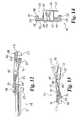
- FIG. 11is a partial section view through line 11 - 11 of FIG. 8 .
- FIG. 12is a section view through line 12 - 12 of FIG. 8 .
- FIG. 13is a section view through line 13 - 13 of FIG. 7 .
- FIG. 14is a section view through line 14 - 14 of FIG. 11 .
- FIG. 15is a top plan view of the second member comprising a part of the distal portion of the instrument of FIG. 1 .
- FIG. 16is a side elevation view of the second member of FIG. 17 .
- FIG. 17is a bottom plan view of the second member of FIG. 17 .
- FIG. 18is a section view through line 18 - 18 of FIG. 17 .
- FIG. 18Ais a section view through line 18 - 18 of FIG. 17 of another second member.
- FIG. 19is a section view through line 19 - 19 of FIG. 17 .
- FIG. 20is a section view through line 20 - 20 of FIG. 17 .
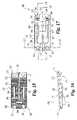
- FIG. 21is a plan view of an actuating member comprising a portion of the instrument of FIG. 1 .
- FIG. 22is an elevation view of the actuating member of FIG. 21 .
- FIG. 23is a section view through line 23 - 23 of FIG. 21 .
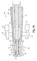
- FIG. 24is a perspective view of the distal portion of the instrument of FIG. 1 in an unexpanded configuration with a combination chisel positioned along a first member of the distal portion thereof.
- FIG. 25is a plan view of the combination chisel of FIG. 24 .
- FIG. 26is a side elevation view of the combination chisel of FIG. 24 .
- FIG. 27is a section view through line 27 - 27 of FIG. 26 .
- FIG. 28is a side elevation view of a keel chisel.
- FIG. 29is a plan view of the keel chisel of FIG. 28 .
- FIG. 30is a plan view of a corner chisel.
- FIG. 31is an elevation view of the corner chisel of FIG. 30 .
- FIG. 32is a perspective view of a distal portion of another embodiment instrument for distracting and facilitating preparation of an intervertebral space.
- FIG. 33is another perspective view of the distal portion of FIG. 32 .
- FIG. 34is a perspective view of the distal portion in FIG. 32 with a second member of the distal portion removed.
- FIG. 35is another perspective view of the distal portion in FIG. 32 with a second member of the distal portion removed.
- FIG. 36is a section view through the distal portion of FIG. 32 .
- FIG. 37is a perspective view of the instrument including the distal portion in FIG. 32 with a second member of the distal portion removed.
- FIG. 38is a perspective view of the instrument including the distal portion in FIG. 32 and a T-handle coupled to the proximal end thereof.
- FIG. 39is another perspective view of the instrument of FIG. 38 with the T-handle removed.
- Instrument 100having a handle assembly 102 extending along longitudinal axis 101 .
- Instrument 100includes a distal portion 104 at a distal end of handle assembly 102 .
- Distal portion 104is positionable in a space between vertebrae and can be remotely manipulated by the surgeon to increase the separation distance and/or angulation between the adjacent vertebrae.
- Distal portion 104includes a first member 106 and a second member 108 .
- the members 106 , 108are in the form of plates having opposite faces positionable against the endplate of an adjacent vertebrae to provide a separation force thereto when manipulated with handle assembly 102 .
- Other forms for members 106 , 108are also contemplated, including single blades, U-shaped blades, or other suitable structure for contacting the adjacent vertebral endplate.
- First and second members 106 , 108are movable relative to one another from an unexpanded configuration, as shown in FIGS. 1-3 , to a second expanded configuration, as shown in FIG. 4 .
- first and second members 106 , 108are positioned adjacent one another to form a low profile configuration for insertion in the space between the vertebrae.
- first member 106 and second member 108are moved away from one another and separated by a distance 110 .
- Distance 110can be increased or decreased by manipulation of handle assembly 102 to provide a desired separation distance between adjacent vertebrae in contact with first and second members 106 , 108 .
- First member 106is coupled with an intermediate shaft 122 extending proximally therefrom.
- First member 106can be integrally formed with intermediate shaft 122 or otherwise attached thereto.
- Intermediate shaft 122is received in a passage formed through an outer shaft 120 .
- Intermediate shaft 122further includes a passage through which an inner shaft 124 extends.
- a handle member 126extends proximally about the proximal ends of shafts 120 , 122 and 124 .
- Outer shaft 120is movable relative to intermediate shaft 122 with thumbwheel 138 .
- Thumbwheel 138is rotatably received in enlarged portion 129 of handle member 126 and threadingly engaged with outer shaft 120 to provide axial adjustment capability for outer shaft 120 relative to intermediate shaft 122 .
- Outer shaft 120includes first and second arms 139 , 141 extending distally and longitudinally from a distal end thereof.
- First arm 139includes a first stop member 140 at a distal end thereof
- second arm 141includes a second stop member 142 at a distal end thereof.
- the distance from stop members 140 , 142 to the distal end 112 of first member 106is indicated by depth markings along outer shaft 120 , which are visible through a window 135 formed in handle member 126 .
- First and second stop members 140 , 142extend transversely to longitudinal axis 101 and project outwardly from first member 106 .
- First and second stop members 140 , 142contact the adjacent vertebral body to limit the depth of insertion of distal portion 104 into the space between vertebrae.
- First and second stop members 140 , 142are adjustable relative to intermediate shaft 122 and first member 106 with thumbwheel 138 to allow the desired insertion depth limit into the disc space for distal portion 104 to be adjusted by the surgeon
- Inner shaft 124includes an actuating member 152 coupled to a distal end thereof.
- Actuating member 152is positioned between first member 106 and second member 108 .
- Actuating member 152is movable distally relative to first and second members 106 , 108 with inner shaft 124 to move first and second members 106 , 108 toward the expanded configuration.
- a distraction indicator 132 coupled to inner shaft 124moves longitudinally therewith to provide an indication of the position of actuating member 152 relative to first and second members 106 , 108 .
- Distraction height indicia 133 on handle member 126correspond to the distraction height of first and second members 106 , 108 provided by the longitudinal positioning of actuating member 152 therebetween.
- inner shaft 124is axially movable relative to intermediate shaft 122 and outer shaft 120 by coupling a T-handle (not shown) to connector 128 .
- Connector 128can be a Hudson type connector or any other suitable structure for engagement with the T-handle.
- Connector 128extends into handle member 126 and is threadingly engaged with a proximal end of inner shaft 124 .
- An end cap 130centers connector 128 in the proximal end opening of handle member 126 .
- Rotation of connector 128 in one of the clockwise or counter-clockwise directionsresults in distal axial movement of inner shaft 124 and actuating member 152 , causing first and second members 106 , 108 to move toward their expanded configuration.
- Rotation of connector 128 in the opposite directionresults in proximal axial movement of inner shaft 124 and actuating member 152 , allowing first and second members 106 , 108 to return toward their unexpanded configuration.
- Handle assembly 102further includes a coupling member 131 extending about intermediate shaft 122 and keyed with the sides thereof to prevent intermediate shaft 122 from rotating with the rotation of inner shaft 124 .
- Coupling member 131further releasably secures handle member 126 to intermediate shaft 122 .
- Coupling member 131can be accessed and removed to allow disassembly of handle assembly 102 to facilitate cleaning of instrument 100 .
- First member 106includes a plate-like body 180 forming a distal extension of intermediate shaft 122 .
- Body 180extends between a distal end 112 and a proximal end 113 .
- Body 180includes an outer surface 182 having a number of V-shaped, elongated recesses 184 formed therein. Recesses 184 provide frictional engagement with the adjacent vertebral endplate, and resist movement of first member 106 relative to the vertebrae during the surgical procedure.
- Body 180includes an inner surface 186 configured to co-act with actuating member 152 and second member 108 to couple first and second members 106 , 108 to one another and to move between the expanded and unexpanded positions.
- Body 180extends along a central axis 181 and includes a central keyway 192 extending from proximal end 113 along axis 181 along a portion of the length of body 180 .
- Keyway 192opens along outer surface 182 .
- Body 180further includes grooves 188 , 190 offset from and extending along axis 181 that open toward outer surface 182 and proximal end 113 .
- Arms 139 , 141 of outer shaft 120are slidably received and recessed in respective ones of the grooves 188 , 190 .
- Body 180further includes lateral actuator slots 194 , 195 and medial actuator slots 196 , 197 extending between and opening at each of the outer and inner surfaces 182 , 186 .
- Medial slots 196 , 197are offset distally relative to lateral slots 194 , 195 .
- Slot 194includes an intermediate surface 198 oriented toward outer surface 182 that supports the enlarged head of an engagement member of the actuating member, as discussed further below.
- Slot 194further includes an enlarged distal end 199 through which the enlarged head of a corresponding engagement member of the actuating member can be positioned to couple actuating member 152 thereto.
- Each of the slots 195 , 196 , 197similarly include an intermediate surface and enlarged distal end for receiving a corresponding enlarged head of an engagement member of actuating member 152 .
- medial slot 196includes an intermediate surface 200 for supporting the underside of the enlarged head of the corresponding engagement member of actuating member 152 as it moves therealong.
- Inner surface 186includes a cam surface 202 extending along axis 181 .
- Cam surface 202extends along a distal projection portion 204 adjacent distal end 112 and a proximal recessed portion 206 adjacent proximal end 113 , as shown in FIGS. 11-13 .
- Projection portion 204projects downwardly toward second member 108 adjacent distal end 112 , as best shown in FIGS. 9 and 11 - 13 .
- Recessed portion 206extends into body 180 adjacent proximal end 113 , as best shown in FIGS. 11-13 .
- Cam surface 202forms angle 207 with central axis 181 . In one embodiment, angle 207 is 17.5 degrees; however, other cam surface angles are also contemplated.
- the intermediate surfaces of slots 194 , 195 , 196 , 197such as intermediate surfaces 198 , 200 shown in FIGS. 11 and 12 , extend parallel to cam surface 202 to facilitate movement of actuating member 152 therealong.
- First member 106includes a first distal arm 208 and a second distal arm 210 on opposite sides of central axis 181 . Distal arms 208 , 210 project toward second member 108 adjacent distal end 112 .
- a first passage 216extends from inner surface 186 and opens at outer surface 182 along the proximal side of first distal arm 208
- a second passage 218extends from inner surface 186 and opens at outer surface 182 along the proximal side of second distal arm 210 .
- First member 106further includes a first proximal post 220 and a second proximal post 222 on opposite sides of axis 181 that project from inner surface 186 adjacent proximal end 113 toward second member 108 .
- Second member 108includes a plate-like body 230 that is coupled to first member 106 with actuating member 152 .
- Body 230extends between a distal end 250 and a proximal end 251 .
- Body 230includes an outer surface 232 having a number of V-shaped grooves 234 formed therein. Grooves 234 provide frictional engagement with the adjacent vertebral endplate, and resist movement of second member 108 relative to the vertebrae during the surgical procedure.
- Body 230includes an inner surface 236 configured to co-act with actuating member 152 to couple first and second members 106 , 108 to one another during movement between the expanded and unexpanded configurations.
- Body 230extends along a central axis 231 and includes a central keyway 242 extending from proximal end 251 along axis 231 along a portion of the length of body 230 .
- Keyway 242opens along outer surface 232 .
- Body 180further includes actuator slots 244 , 245 extending between and opening toward each of the outer and inner surfaces 232 , 236 .
- Slot 244includes an intermediate surface 248 oriented toward outer surface 232 that supports the head of an engagement member of the actuating member, as discussed further below.
- Slot 244further includes an enlarged distal end 249 through which the head of the engagement member of the actuating member is positioned to couple the actuating member 152 thereto.
- Slot 245similarly includes an intermediate surface and enlarged distal end for receiving a corresponding engagement member of the actuating member 152 .
- Inner surface 236includes a cam surface 252 extending along axis 181 .
- Cam surface 252extends along distal projection portions 254 , 255 adjacent distal end 250 and a proximal recess portion 256 adjacent proximal end 251 , as shown in FIG. 20 .
- Projection portions 254 , 255project toward first member 106 , as shown in FIGS. 16 and 18 - 19 .
- Recess portion 256extends into body 230 adjacent proximal end 251 , as best shown in FIGS. 18-19 .
- Cam surface 252forms angle 257 with central axis 231 .
- angle 257is the same as cam surface angle 207 of first member 106 and is 17.5 degrees; however, other cam surface angles are also contemplated.
- the intermediate surfaces of slots 244 , 245such as intermediate surface 248 shown in FIG. 19 , extends parallel to cam surface 252 to facilitate movement of actuating member 152 therealong.
- Second member 108includes a first proximal receiving member 258 and a second proximal receiving member 260 on opposite sides of central axis 231 .
- Receiving members 258 , 260project toward first member 106 .
- Receiving member 258includes a passage 259 extending therethrough and opening at outer surface 232
- receiving member 260includes a passage 261 extending therethrough and opening at outer surface 232 .
- Second member 108further includes a first distal notch 262 and a second distal notch 264 each opening toward distal end 250 .
- a central receptacle 266opens toward outer surface 232 and inner surface 236 , and is located distally of central keyway 242 .
- Shaft receptacle 272is positioned between receiving members 258 , 260 to receive the distal end of intermediate shaft 122 in the unexpanded configuration.
- Actuating member 152includes a wedge-shaped body 154 having a first surface 155 and an opposite second surface 157 .
- Surfaces 155 , 157taper toward one another from proximal end 158 to distal end 156 when actuating member 152 is positioned between first and second members 106 , 108 .
- proximal end 158has a thickness greater than that of distal end 156 .
- a pair of distal engagement members 162extend from first surface 155 adjacent distal end 156
- a pair of proximal engagement members 160extend from first surface 155 adjacent proximal end 158
- Proximal engagement members 160are slidably received within respective ones of the lateral slots 194 , 195 of first member 106
- distal engagement members 162are slidably received within respective ones of the medial slots 196 , 197 of first member 106
- a pair of opposite engagement members 164extend from second surface 157 and are slidingly received within respective ones of the actuator slots 244 , 245 of second member 108 .
- Each of the engagement members 160 , 162 , 164includes an enlarged head portion positionable through the enlarged distal end opening of the corresponding slot, and engages intermediate surface of the corresponding slot when moved proximally from the enlarged distal opening. Engagement of actuator 152 within the slots couples second member 108 to first member 106 .
- Actuating member 152further includes a proximally opening notch 166 extending along proximal end 158 toward distal end 156 along a portion of first and second surface 155 , 157 .
- Inner shaft 124includes a flanged distal end 125 slidably coupled to actuating member 152 in grooved portion 167 of notch 166 , as shown in FIG. 6 . It is contemplated that actuator 152 moves up and down along flanged distal end 125 of inner shaft 124 as actuating member is moved along the cam surfaces of first and second members 106 , 108 .
- actuating member 152When distal portion 104 is assembled, actuating member 152 is located between and movably coupled to first and second members 106 , 108 .
- Proximal engagement members 160are slidably received in respective ones of the lateral actuator slots 194 , 195 of first member 106
- distal engagement members 162are slidably received in medial actuator slots 196 , 197 of first member 106 .
- engagement members 164are slidably received in actuator slots 244 , 245 of second member 108 .
- the enlarged heads of engagement members 160 , 162 , 164extend along the intermediates surfaces of the actuator slots to secure the first and second members 106 , 108 to actuating member 152 .
- actuating member 152contacts cam surface 202 of first member 106
- surface 157 of actuating member 152contacts cam surface 252 of second member 108
- Surfaces 155 , 157are angled relative to one another to match the cam surface angles 207 , 257 formed by cam surfaces 202 , 252 .
- actuating member 152is located in recessed portions 206 , 256 so that inner surfaces 186 , 206 are positioned adjacent to one another.
- actuating member 152is moved distally along cam surfaces 202 , 252 along the respective distal projection portion 204 of first member 206 and distal projection portions 254 , 255 of second member 208 .
- actuating member 152moves first and second members 106 , 108 away from one another toward the expanded configuration.
- Actuating member 152acts on cam surfaces 202 , 252 so that the distal ends 112 , 250 are moved away from one another the same distance that proximal ends 113 , 251 are moved away from one another.
- actuating member 152can be configured so that its rotation about the longitudinal axis of instrument 100 moves first and second members 106 , 108 toward the expanded configuration.
- actuating member 152can be rotated about the longitudinal axis of the instrument and simultaneously moved along the longitudinal axis of the instrument to move first and second members 106 , 108 toward the expanded configuration.
- first and second members 106 , 108are assembled in interfitting recesses and projections of the other of the first and second members.
- distal projection portion 204 of first member 106is aligned with and received in central receptacle 266 of second member 108
- distal arms 208 , 210 of first member 106are aligned with and received in distal notches 264 , 262 of second member 108 .
- Proximal posts 220 , 222 of first member 106are aligned with and received in the passages of the corresponding proximal receiving member 260 , 258 of second member 108 .
- Distal projection portions 254 , 255 of second member 108are aligned with and received in respective ones of the first and second passages 216 , 218 of first member 106 in the unexpanded configuration.
- first and second members 106 , 108define a pair of opposed outer surfaces 182 , 232 .
- the outer surfaces 182 , 232are sized to be inserted into an intervertebral disc space and are adapted to contact and securely engage opposing faces of the adjacent vertebrae.
- outer surfaces 182 , 232define a number of surface features that aid in engaging and gripping the vertebral endplates of the adjacent vertebrae, such as recesses 184 , 234 .
- recesses 184 , 234are V-shaped and arranged at approximately a 45° angle across the respective outer surface 182 , 232 and extend orthogonally to longitudinal axis 101 .
- the outer surfaces 182 , 232are generally planar and are of uniform relative separation across their widths in a direction transverse to longitudinal axis 101 such that a cross section of the first and second members 106 , 108 perpendicular to the longitudinal axis 101 is generally rectangular.
- Other cross sectional profilesincluding profiles that vary along the longitudinal axis 101 could also be employed.
- Outer surfaces 182 , 232can be tapered relative to one another and oriented to form an angle 103 such that the degree of angular separation between the outer surfaces 132 , 182 decreases towards the distal ends 112 , 250 of first and second members 106 , 108 .
- the angle 103 defined between outer surfaces 182 , 232can correspond to the particular lordotic angle desired between the endplates of the vertebrae on each side of the intervertebral disc space, and may take on any number of specific values, including 6°, 9°, and 12°, for example. It should be understood, however, that other angles 103 are contemplated, including angles at or near 0° where outer surfaces 182 , 232 are arranged substantially parallel to one another. Still other embodiments contemplate variable or kyphotic angles between the outer surfaces 182 , 232 .
- first member 106includes outer surface 182 that is oriented at angle 183 relative to central axis 181 , as shown in FIG. 11 .
- second member 108includes an outer surface 232 oriented at an angle 233 relative to a plane that extends parallel to axis 181 when first and second members 106 , 108 are assembled. Accordingly, overall angle 103 is equal to the sum of angles 183 and 233 when first and second members 106 , 108 are assembled. Providing first and second members 106 , 108 with angles 183 , 233 of 3 degrees results in an overall angle 103 of 6 degrees.
- Second member 108can be readily separated from distal portion 104 by advancing actuating member 152 distally far enough to align engagement members with the enlarged distal end opening of actuator slots 244 , 245 .
- instrument 100can be provided in a kit with a number of second members 108 including outer surfaces 232 oriented at various angles 233 to allow the surgeon to attach a selected second member 108 with first member 106 to provide the desired overall angle 103 .
- FIG. 18Ashows diagrammatically another second member 108 with outer surface 232 oriented at an angle 233 different than angle 233 of FIG. 18 .
- Instrument 100can be used to distract and facilitate preparation of an intervertebral disc space for implantation of a spinal implant between the adjacent vertebrae.
- instrument 100may be used to prepare an intervertebral disc space for insertion of the intervertebral disc prosthesis disclosed in U.S. patent application Ser. No. 10/042,589, filed on Jan. 9, 2002, and entitled Intervertebral Prosthetic Joint, the contents of which are hereby incorporated by reference in their entirety.
- Instrument 100is adapted for use in conjunction with various surgical cutting instruments to prepare the adjacent vertebrae for insertion of a spinal implant therebetween.
- instrument 100also functions as a jig or guiding instrument for surgical instruments that serve to cut, shave, bore, or otherwise prepare the vertebral endplates and/or disc space for insertion and engagement of an implant.
- An example of one such instrumentis a chisel 300 , as depicted in FIGS. 25-27 , and shown with instrument 100 in FIG. 24 .
- Other examplesinclude a keel chisel 400 as shown FIGS. 28-29 , and a corner chisel 500 as shown in FIGS. 30-31 .
- first and second members 106 , 108can each include one or more guiding features that interact with the cutting instrument to guide the cutting instrument along the outer surface of the first and second members 106 , 108 .
- first member 106includes beveled sidewalls 224 , 226 extending along the outer lateral sides thereof as shown in FIGS. 10 , 14 .
- a first support member 225extends along first sidewall 224
- a second support memberextends along second sidewall 226 .
- First member 106further includes central keyway 192 as shown in FIG. 7 .
- second member 108includes a first beveled sidewall 268 and an opposite second beveled sidewall 270 as shown in FIG. 20 .
- a first support member 269extends along first sidewall 268
- a second support member 271extends along second sidewall 270 .
- Second member 108further includes central keyway 242 as shown in FIG. 15 .
- Actuating member 152can be confined between first and second members 106 , 108 by contact with inner lateral surfaces of the sidewalls. Alternatively or additionally, actuating member 152 can be confined between the sidewalls of first and second members 106 , 108 by the engagement of the engagement members of actuating member 152 with the respective slots in first and second members 106 , 108 . Other embodiments contemplate actuating member 152 projecting laterally beyond one or both of the sidewalls of first and second members 106 , 108 .
- combination chisel 300includes a handle connector 310 , a shaft assembly 315 , a keel blade 320 , and a pair of corner blades 330 extending along opposite sides of keel blade 320 .
- Keel blade 320is centrally located between corner blades 330
- cross member 302extends between and interconnects corner blades 330 and keel blade 320 at their proximal ends.
- Pins 304extend from cross member 302 and contact the proximal end of the first or second member 106 , 108 to limit the insertion depth of chisel 300 relative thereto.
- Shaft assembly 315includes first shaft portion 316 and second shaft portion 318 that extend from handle connector 310 to respective ones of the corner blades 330 .
- Shaft assembly 315forms a triangular opening with cross member 302 that facilitates visualization of the distal portion of the instrument assembly.
- Handle connector 310provides a connection mechanism for removable connection of a handle that allows insertion and withdrawal of chisel 300 . The handle can be removed to facilitate visualization during the surgical procedure.
- Keel blade 320includes distal cutting end 322 for penetrating the vertebral body and forming a vertically oriented slot in the vertebral body as keel blade 320 is advanced therein.
- Keel blade 320includes a tapered proximal end 324 that extends to cross member 302 .
- Chisel 300also includes an elongated guiding fin 325 disposed generally opposite the keel blade 320 , as shown in FIG. 27 .
- Guiding fin 325is configured to be slidably received within the corresponding keyway 192 , 242 of the first or second member 106 , 108 , respectively.
- Guiding fin 325extends downwardly from keel blade 320 and generally includes an enlarged end that fits within the keyway 192 , 242 and restrains chisel 300 vertically relative thereto.
- Corner blades 330each include a guide portion 332 that is received in the corresponding beveled sidewall 224 , 226 of first member 106 , and in the beveled sidewalls 268 , 270 of second member 108 , as shown in FIG. 24 . Corner blades 330 further include a cutting portion 334 that includes a sharpened distal end 335 and forms channel 336 along guide portion 332 . Channel 336 collects bone or other cut material removed by cutting portion 334 as chisel 330 is advanced along the respective first or second member 106 , 108 .
- the distal ends of keel blade 320 and corner blades 330are shaped to make the cuts in the vertebral bodies so as to prepare the vertebral body to engage portions of the spinal implant positioned therein.
- FIGS. 28 and 29show a keel chisel 400 that includes a center keel blade 420 .
- Keel blade 420extends distally from a shaft 415 , which includes a handle connector 410 at a proximal end thereof.
- a guiding fin 425extends along the bottom of keel blade 420 and is adapted for positioning in keyways 192 , 242 of first and second members 106 , 108 .
- Keel blade 420includes a sharp blade 422 at a distal end thereof to form a vertically oriented slot in the vertebral body.
- FIGS. 30 and 31show a corner chisel 500 that includes a handle connector 510 , a shaft assembly 515 , a cross member 502 and corner blades 530 .
- Corner blades 530can be configured as discussed above with respect to corner blades 330 of combination chisel 300 .
- Corner chisel 500does not include any keel blade, and thus forms only corner cuts when guided along a respective one of first or second member 106 , 108 positioned in the disc space.
- instrument 100 and a pair of combination chisels 300are used to prepare a disc space for insertion of a spinal prosthesis. From an anterior surgical approach, the distal portion 104 is inserted into a disc space with outer surfaces 182 , 232 of first and second members 106 , 108 oriented toward the adjacent vertebral endplate.
- a guide sleevemay be employed to provide a protected pathway to the disc space if desired.
- first and second members 106 , 108 of instrument 100can be aligned, or nearly aligned, with the posterior edge of the vertebral bodies adjacent the anterior portion of the spinal canal. Such alignment may be used to ensure that the measurement provided by instrument 100 corresponds to the location where the disc prosthesis is to be placed. It should be understood that other prosthesis systems may require different alignments in the disc space. Proper positioning of instrument 100 may be confirmed with a lateral X-ray. If the X-ray and/or other observations indicate a different lordosis angle than the one provided by the selected instrument 100 , instrument 100 is removed. Instrument 100 can then be modified by replacing second member 108 or by selecting a different instrument 100 that provides, for example, a different lordotic angle. The procedure is repeated until an acceptable lordosis angle is achieved.
- the stop members 140 , 142can be adjusted if necessary to engage against the outer surfaces of the vertebral bodies via rotation of the thumbwheel 138 . Stop members 140 , 142 prevent posterior movement of the instrument 100 during the remaining steps in the surgical procedure, protecting the spinal canal and nerve structures from impingement with instrument 100 .
- connector 128When distal portion 104 has been positioned in the desired location in the disc space, connector 128 is engaged with a T-handle or other tool and rotated to distally and axially advance inner shaft 124 . This distally displaces actuating member 152 and separates first and second members 106 , 108 to provide the desired distraction. Actuating member 152 is positioned along the portion of first and second members 106 , 108 that are positioned in the disc space. Thus cantilevering of the portions of first and second members 106 , 108 distally of actuating member 152 is minimized, providing uniform separation of the adjacent vertebrae along the length of first and second members 106 , 108 .
- first and second members 106 , 108are expanded to tension the annulus fibers to firmly seat instrument 100 against the adjacent vertebral endplate in the intervertebral disc space.
- the distraction heightis measured, and if acceptable, disc preparation tools, such as one of chisel instruments discussed above, are positioned adjacent one of the first and second members 106 , 108 and advanced distally therealong to prepare the disc space and adjacent vertebrae for insertion of an implant.
- disc preparation toolssuch as one of chisel instruments discussed above
- the engagement of first and second members 106 , 108 with the vertebral endplates and precise control over the distraction distance provided by instrument 100allows the cuts made by the chisel to be uniform and precisely controlled.
- surgical tools not guided by first and second members 106 , 108may be employed with distal portion inserted in the space or removed therefrom.
- the chisels discussed hereinprovide a variety of chiseling patterns that may be employed by the surgeon during the surgical procedure.
- One exemplary chiseling patternincludes driving keel blade 420 of keel chisel 400 into either the superior or the inferior vertebral body.
- the chisel handlecan be removed, temporarily leaving keel blade 420 in the vertebral body to control bleeding and to improve surgical visibility.
- Either a keel chisel 400 or a combination keel/corner chisel 300is then driven into the opposite vertebral body. If only a keel chisel 400 is employed initially in the opposite vertebral body, it can be followed by a corner chisel 500 .
- the handles of the one or more chisels in the opposite vertebral bodycan then be removed to facilitate visualization and access to the first vertebral body.
- a corner chisel 500can be driven into first vertebral body where keel chisel 400 is maintained. All chisels are then removed.
- first and second members 106 , 108are moved toward their unexpanded configuration and distal portion 104 of instrument 100 is removed from the disc space.
- One or more shims or other temporary distractor(s)may be positioned between the adjacent vertebral bodies prior to removal of instrument 100 to maintain distraction while the spinal implant is inserted in the disc space.
- the implantcan include upper and lower portions that fit within the spaces in the adjacent vertebral body provided by removal of the bone material with the chisels. The implant is then impacted into the prepared site and the shims or other temporary distractors are removed if employed.
- Instrument 100allows the lateral surgical exposure during the preparation of the disc space and vertebral bodies to be maintained at exactly or nearly exactly the width of the prosthesis being implanted.
- Actuating member 152includes a width so that it is contained within first and second member 106 , 108 .
- the corner chisel cutswhich can correspond to the outer lateral perimeter of the prosthesis, are provided by the corner chisel blades.
- First and second members 106 , 108can be provided with a width that is substantially equal to or slightly less than the width of the spinal implant, thus a larger surgical exposure is not required for insertion first and second members 106 , 108 than is required for insertion of the implant.
- additional lateral exposure beyond that dictated by the implant sizeis not necessary, it may be employed if desired.
- Instrument 100may be employed for disc space distraction and vertebral body preparation for insertion of one or more fusion cages, artificial discs, bone spacers, or other devices positionable in the spinal disc space. Instrument 100 can be adapted for use in any approach to the disc space, including anterior, lateral, anterior-oblique, postero-lateral, and transforaminal approaches.
- Instrument 700includes a distal portion 704 positionable in the disc space in an unexpanded configuration and movable to an expanded configuration to distract or separate the adjacent vertebrae.
- Instrument 700can be employed as a jig or guiding instrument in the manner discussed above with respect to instrument 100 , and can include any of the features of instrument 100 .
- Instrument 700extends along a longitudinal axis 701 and includes a handle assembly 702 extending proximally from distal portion 704 .
- Distal portion 704includes a first member 706 and a second member 708 .
- handle assembly 702includes a proximal gripping portion 748 and an elongate outer shaft 730 that is coupled to and extends distally from gripping portion 748 .
- An inner shaft 735is rotatably positioned in outer shaft 730 , and includes a proximal end coupling member 732 adapted to engage, for example, a T-handle 780 .
- first and second members 706 , 708When assembled, first and second members 706 , 708 define a pair of opposed outer engaging surfaces 712 , 722 .
- Engaging surfaces 712 , 722contact the adjacent vertebral endplates and exert a distraction force thereon when first and second members 706 , 708 are separated from one another.
- Engaging surfaces 712 , 722can include recesses or other surface features to facilitate engagement with the adjacent vertebral endplate.
- Engaging surfaces 712 , 722can also be angled relative to one another, or parallel to one another, as discussed above with respect to instrument 100 .
- First member 706is coupled to second member 708 with alignment posts 714 extending from an inner surface 736 of second member 708 .
- Three alignment postsare shown, although less than three or more than three alignment posts are also contemplated.
- Alignment posts 714are received within the corresponding alignment openings 715 extending through first member 706 , and resist first and second members 706 , 708 from twisting relative to one another.
- a fastener 717is secured to second member 708 and includes an enlarged head captured in receptacle 710 of first member 706 .
- Receptacle 710includes a inner flange 711 that contacts the enlarged head of fastener 717 to limit the movement of first member 706 away from second member 708 and to retain first and second members 706 , 708 together.
- Fastener 717can be adjusted to position the enlarged head 718 relative to second member 708 to provide the desired maximum distraction height.
- the outer shaft 730includes a passage therethrough through which an inner shaft 735 extends.
- Inner shaft 735is operable with T-handle 780 to actuate a distal actuating member 790 and a proximal actuating member 792 positioned about an actuator shaft 794 .
- Proximal actuating member 792is slidable on actuator shaft 794 .
- Actuator shaft 794includes a hexagonal head 795 at a distal end thereof non-rotatably received in distal actuating member 790 .
- inner shaft 735As inner shaft 735 is threaded or otherwise advanced distally along actuator shaft 794 , the distal end of inner shaft 735 bears against and pushes proximal actuating member 792 distally and actuator shaft 794 simultaneously pulls distal actuating member 790 proximally.
- This movement initiated through rotation of inner shaft 735forces actuating members 790 , 792 together along actuator shaft 794 and along inner surface 720 of first member 706 , and also along distal inner cam surface 725 and proximal inner cam surface 723 of second member 706 as shown in FIG. 36 .
- the inner cam surfaces 723 , 725are inclined toward one another and meet at an apex therebetween.
- the inclined cam surfaces 723 , 725displace actuating members 790 , 792 moving therealong toward first member 706 and cause first member 706 to move away from second member 708 .
- a notch 734 in cam surfaces 723 , 725accommodates actuator shaft 794 .
- each actuating member 790 , 792are slottedly engaged with rails 726 , 727 of second member 708 to maintain actuating members 790 , 792 in engagement with second member 708 and to restrict lateral movement of actuating members 790 , 792 .
- First member 706includes a pair of outwardly extending arms 742 .
- Arms 742each define a hole that receives a positive stop 746 .
- Stop 746is threadedly received inside the hole such that stop 746 is adjustable relative to first member 706 , and extend distally from arms 742 to abut the vertebral body when positioned thereagainst. Stops 746 can be adjusted to adjust the insertion depth of distal portion 704 in the disc space.
- Second member 708can similarly include a pair of outwardly extending arms 744 for receiving a threaded positive stop.
- first and second members 706 , 708can include means for guiding engagement with disc preparation and/or vertebral body instruments.
- First member 706includes a proximal mounting portion 750 that extends along a distal portion of outer shaft 730 .
- Second member 708includes a proximal mounting portion 752 that extends along a distal portion of outer shaft 730 and includes a mounting member 738 mounted with outer shaft 730 .
- Proximal mounting portion 750is movable relative to outer shaft 730 and proximal mounting portion 752 in response to the expansion of first member 706 with actuating members 790 , 792 .
- Proximal mounting portion 750includes a central keyway 780 .
- Keyway 780can include a dovetail configuration with a pair of angled surfaces converging towards a narrower opening along the outer surface of proximal mounting portion 750 .
- Keyway 780can receive a guiding fin of a keel chisel, such as is provided with keel chisel 400 or combination chisel 300 discussed above.
- Support for the corner blades of a corner chisel, or of the corner blades of a combination chisel,can be provided by lateral surfaces 782 of first member 706 . Lateral surfaces 782 are offset below engaging surface 712 to facilitate passage of the corner blade therealong.
- Proximal mounting portion 752can similarly be provided with a central keyway and lateral surfaces offset from engaging surfaces 722 . Arms 742 , 744 can contact the chisel to limit the insertion depth of the chisel blades into the disc space.
Landscapes
- Health & Medical Sciences (AREA)
- Life Sciences & Earth Sciences (AREA)
- Biomedical Technology (AREA)
- Engineering & Computer Science (AREA)
- Orthopedic Medicine & Surgery (AREA)
- Surgery (AREA)
- Veterinary Medicine (AREA)
- Heart & Thoracic Surgery (AREA)
- Animal Behavior & Ethology (AREA)
- General Health & Medical Sciences (AREA)
- Public Health (AREA)
- Oral & Maxillofacial Surgery (AREA)
- Nuclear Medicine, Radiotherapy & Molecular Imaging (AREA)
- Medical Informatics (AREA)
- Molecular Biology (AREA)
- Dentistry (AREA)
- Neurology (AREA)
- Transplantation (AREA)
- Cardiology (AREA)
- Vascular Medicine (AREA)
- Physical Education & Sports Medicine (AREA)
- Prostheses (AREA)
- Surgical Instruments (AREA)
Abstract
Description
Claims (44)
Priority Applications (1)
| Application Number | Priority Date | Filing Date | Title |
|---|---|---|---|
| US10/768,354US7547308B2 (en) | 2002-05-06 | 2004-01-30 | Instrumentation and methods for preparation of an intervertebral space |
Applications Claiming Priority (4)
| Application Number | Priority Date | Filing Date | Title |
|---|---|---|---|
| US37856802P | 2002-05-06 | 2002-05-06 | |
| US43047303A | 2003-05-06 | 2003-05-06 | |
| PCT/US2003/014170WO2003092507A2 (en) | 2002-05-06 | 2003-05-06 | Instrumentation and methods for preparation of an intervertebral space |
| US10/768,354US7547308B2 (en) | 2002-05-06 | 2004-01-30 | Instrumentation and methods for preparation of an intervertebral space |
Related Parent Applications (2)
| Application Number | Title | Priority Date | Filing Date |
|---|---|---|---|
| US43047303AContinuation | 2002-05-06 | 2003-05-06 | |
| PCT/US2003/014170ContinuationWO2003092507A2 (en) | 2002-05-06 | 2003-05-06 | Instrumentation and methods for preparation of an intervertebral space |
Publications (2)
| Publication Number | Publication Date |
|---|---|
| US20050113842A1 US20050113842A1 (en) | 2005-05-26 |
| US7547308B2true US7547308B2 (en) | 2009-06-16 |
Family
ID=29401610
Family Applications (1)
| Application Number | Title | Priority Date | Filing Date |
|---|---|---|---|
| US10/768,354Expired - LifetimeUS7547308B2 (en) | 2002-05-06 | 2004-01-30 | Instrumentation and methods for preparation of an intervertebral space |
Country Status (6)
| Country | Link |
|---|---|
| US (1) | US7547308B2 (en) |
| EP (1) | EP1503672A2 (en) |
| JP (1) | JP4388468B2 (en) |
| AU (1) | AU2003234508A1 (en) |
| CA (1) | CA2485015A1 (en) |
| WO (1) | WO2003092507A2 (en) |
Cited By (47)
| Publication number | Priority date | Publication date | Assignee | Title |
|---|---|---|---|---|
| US20070118145A1 (en)* | 2005-11-24 | 2007-05-24 | Kay Fischer | Surgical guiding instrument |
| US20070191857A1 (en)* | 2006-01-31 | 2007-08-16 | Sdgi Holdings, Inc. | Spinal disc replacement surgical instrument and methods for use in spinal disc replacement |
| US20080015694A1 (en)* | 2006-01-13 | 2008-01-17 | Clifford Tribus | Spine reduction and stabilization device |
| US20110054548A1 (en)* | 2009-09-03 | 2011-03-03 | Zimmer Spine, Inc. | Spinal implant delivery methods and devices |
| US8012207B2 (en) | 2004-10-20 | 2011-09-06 | Vertiflex, Inc. | Systems and methods for posterior dynamic stabilization of the spine |
| US8123807B2 (en) | 2004-10-20 | 2012-02-28 | Vertiflex, Inc. | Systems and methods for posterior dynamic stabilization of the spine |
| US8123782B2 (en) | 2004-10-20 | 2012-02-28 | Vertiflex, Inc. | Interspinous spacer |
| US8128662B2 (en) | 2004-10-20 | 2012-03-06 | Vertiflex, Inc. | Minimally invasive tooling for delivery of interspinous spacer |
| US8152837B2 (en) | 2004-10-20 | 2012-04-10 | The Board Of Trustees Of The Leland Stanford Junior University | Systems and methods for posterior dynamic stabilization of the spine |
| US8167944B2 (en) | 2004-10-20 | 2012-05-01 | The Board Of Trustees Of The Leland Stanford Junior University | Systems and methods for posterior dynamic stabilization of the spine |
| US8273108B2 (en) | 2004-10-20 | 2012-09-25 | Vertiflex, Inc. | Interspinous spacer |
| US8277488B2 (en) | 2004-10-20 | 2012-10-02 | Vertiflex, Inc. | Interspinous spacer |
| US8292922B2 (en) | 2004-10-20 | 2012-10-23 | Vertiflex, Inc. | Interspinous spacer |
| US8317864B2 (en) | 2004-10-20 | 2012-11-27 | The Board Of Trustees Of The Leland Stanford Junior University | Systems and methods for posterior dynamic stabilization of the spine |
| US8409282B2 (en) | 2004-10-20 | 2013-04-02 | Vertiflex, Inc. | Systems and methods for posterior dynamic stabilization of the spine |
| US8425559B2 (en) | 2004-10-20 | 2013-04-23 | Vertiflex, Inc. | Systems and methods for posterior dynamic stabilization of the spine |
| US8613747B2 (en) | 2004-10-20 | 2013-12-24 | Vertiflex, Inc. | Spacer insertion instrument |
| US8628574B2 (en) | 2004-10-20 | 2014-01-14 | Vertiflex, Inc. | Systems and methods for posterior dynamic stabilization of the spine |
| US8740948B2 (en) | 2009-12-15 | 2014-06-03 | Vertiflex, Inc. | Spinal spacer for cervical and other vertebra, and associated systems and methods |
| US8845726B2 (en) | 2006-10-18 | 2014-09-30 | Vertiflex, Inc. | Dilator |
| US8864828B2 (en) | 2004-10-20 | 2014-10-21 | Vertiflex, Inc. | Interspinous spacer |
| US8945183B2 (en) | 2004-10-20 | 2015-02-03 | Vertiflex, Inc. | Interspinous process spacer instrument system with deployment indicator |
| US9023084B2 (en) | 2004-10-20 | 2015-05-05 | The Board Of Trustees Of The Leland Stanford Junior University | Systems and methods for stabilizing the motion or adjusting the position of the spine |
| US9119680B2 (en) | 2004-10-20 | 2015-09-01 | Vertiflex, Inc. | Interspinous spacer |
| US9161783B2 (en) | 2004-10-20 | 2015-10-20 | Vertiflex, Inc. | Interspinous spacer |
| US9393055B2 (en) | 2004-10-20 | 2016-07-19 | Vertiflex, Inc. | Spacer insertion instrument |
| US9675303B2 (en) | 2013-03-15 | 2017-06-13 | Vertiflex, Inc. | Visualization systems, instruments and methods of using the same in spinal decompression procedures |
| US9788971B1 (en) | 2013-05-22 | 2017-10-17 | Nuvasive, Inc. | Expandable fusion implant and related methods |
| US9801734B1 (en) | 2013-08-09 | 2017-10-31 | Nuvasive, Inc. | Lordotic expandable interbody implant |
| US9867714B1 (en) | 2011-09-23 | 2018-01-16 | Samy Abdou | Spinal fixation devices and methods of use |
| US10111757B2 (en) | 2012-10-22 | 2018-10-30 | Cogent Spine, LLC | Devices and methods for spinal stabilization and instrumentation |
| US10195053B2 (en) | 2009-09-18 | 2019-02-05 | Spinal Surgical Strategies, Llc | Bone graft delivery system and method for using same |
| US10245159B1 (en) | 2009-09-18 | 2019-04-02 | Spinal Surgical Strategies, Llc | Bone graft delivery system and method for using same |
| US10524772B2 (en) | 2014-05-07 | 2020-01-07 | Vertiflex, Inc. | Spinal nerve decompression systems, dilation systems, and methods of using the same |
| US10543107B2 (en) | 2009-12-07 | 2020-01-28 | Samy Abdou | Devices and methods for minimally invasive spinal stabilization and instrumentation |
| US10548740B1 (en) | 2016-10-25 | 2020-02-04 | Samy Abdou | Devices and methods for vertebral bone realignment |
| US10695105B2 (en) | 2012-08-28 | 2020-06-30 | Samy Abdou | Spinal fixation devices and methods of use |
| US10857003B1 (en) | 2015-10-14 | 2020-12-08 | Samy Abdou | Devices and methods for vertebral stabilization |
| US10918498B2 (en) | 2004-11-24 | 2021-02-16 | Samy Abdou | Devices and methods for inter-vertebral orthopedic device placement |
| US10973648B1 (en) | 2016-10-25 | 2021-04-13 | Samy Abdou | Devices and methods for vertebral bone realignment |
| US10973656B2 (en) | 2009-09-18 | 2021-04-13 | Spinal Surgical Strategies, Inc. | Bone graft delivery system and method for using same |
| US11006982B2 (en) | 2012-02-22 | 2021-05-18 | Samy Abdou | Spinous process fixation devices and methods of use |
| US11179248B2 (en) | 2018-10-02 | 2021-11-23 | Samy Abdou | Devices and methods for spinal implantation |
| US12102542B2 (en) | 2022-02-15 | 2024-10-01 | Boston Scientific Neuromodulation Corporation | Interspinous spacer and methods and systems utilizing the interspinous spacer |
| US12318307B2 (en) | 2021-07-16 | 2025-06-03 | Blue Ocean Spine Gmbh | Adjustable spinal implants, associated instruments and methods |
| US12390340B2 (en) | 2023-03-15 | 2025-08-19 | Boston Scientific Neuromodulation Corporation | Interspinous spacer with a range of deployment positions and methods and systems |
| US12433646B2 (en) | 2023-02-21 | 2025-10-07 | Boston Scientific Neuromodulation Corporation | Interspinous spacer with actuator locking arrangements and methods and systems |
Families Citing this family (135)
| Publication number | Priority date | Publication date | Assignee | Title |
|---|---|---|---|---|
| US20080027552A1 (en)* | 1997-01-02 | 2008-01-31 | Zucherman James F | Spine distraction implant and method |
| US20080039859A1 (en)* | 1997-01-02 | 2008-02-14 | Zucherman James F | Spine distraction implant and method |
| US8038713B2 (en) | 2002-04-23 | 2011-10-18 | Spinecore, Inc. | Two-component artificial disc replacements |
| US20080027548A9 (en) | 2002-04-12 | 2008-01-31 | Ferree Bret A | Spacerless artificial disc replacements |
| US8388684B2 (en) | 2002-05-23 | 2013-03-05 | Pioneer Signal Technology, Inc. | Artificial disc device |
| US7909853B2 (en)* | 2004-09-23 | 2011-03-22 | Kyphon Sarl | Interspinous process implant including a binder and method of implantation |
| US7497859B2 (en)* | 2002-10-29 | 2009-03-03 | Kyphon Sarl | Tools for implanting an artificial vertebral disk |
| US7833246B2 (en) | 2002-10-29 | 2010-11-16 | Kyphon SÀRL | Interspinous process and sacrum implant and method |
| ZA200506029B (en) | 2003-01-31 | 2006-10-25 | Spinalmotion Inc | Spinal Midline Indicator |
| WO2004066884A1 (en) | 2003-01-31 | 2004-08-12 | Spinalmotion, Inc. | Intervertebral prosthesis placement instrument |
| US7828849B2 (en) | 2003-02-03 | 2010-11-09 | Warsaw Orthopedic, Inc. | Expanding interbody implant and articulating inserter and method |
| US6908484B2 (en) | 2003-03-06 | 2005-06-21 | Spinecore, Inc. | Cervical disc replacement |
| US7442211B2 (en) | 2003-05-27 | 2008-10-28 | Spinalmotion, Inc. | Intervertebral prosthetic disc |
| US10052211B2 (en) | 2003-05-27 | 2018-08-21 | Simplify Medical Pty Ltd. | Prosthetic disc for intervertebral insertion |
| US7575599B2 (en) | 2004-07-30 | 2009-08-18 | Spinalmotion, Inc. | Intervertebral prosthetic disc with metallic core |
| US7153325B2 (en)* | 2003-08-01 | 2006-12-26 | Ultra-Kinetics, Inc. | Prosthetic intervertebral disc and methods for using the same |
| US7520899B2 (en) | 2003-11-05 | 2009-04-21 | Kyphon Sarl | Laterally insertable artificial vertebral disk replacement implant with crossbar spacer |
| US7585326B2 (en) | 2004-08-06 | 2009-09-08 | Spinalmotion, Inc. | Methods and apparatus for intervertebral disc prosthesis insertion |
| US7776045B2 (en) | 2004-08-20 | 2010-08-17 | Warsaw Orthopedic, Inc. | Instrumentation and methods for vertebral distraction |
| DE102004043995A1 (en) | 2004-09-08 | 2006-03-30 | Aesculap Ag & Co. Kg | Surgical instrument |
| EP1652479B1 (en) | 2004-10-27 | 2008-02-20 | BrainLAB AG | Spine distractor with markers |
| US8083797B2 (en) | 2005-02-04 | 2011-12-27 | Spinalmotion, Inc. | Intervertebral prosthetic disc with shock absorption |
| US8096995B2 (en)* | 2005-02-17 | 2012-01-17 | Kyphon Sarl | Percutaneous spinal implants and methods |
| US20070276373A1 (en)* | 2005-02-17 | 2007-11-29 | Malandain Hugues F | Percutaneous Spinal Implants and Methods |
| US7927354B2 (en)* | 2005-02-17 | 2011-04-19 | Kyphon Sarl | Percutaneous spinal implants and methods |
| US7993342B2 (en) | 2005-02-17 | 2011-08-09 | Kyphon Sarl | Percutaneous spinal implants and methods |
| US7998208B2 (en)* | 2005-02-17 | 2011-08-16 | Kyphon Sarl | Percutaneous spinal implants and methods |
| US8096994B2 (en) | 2005-02-17 | 2012-01-17 | Kyphon Sarl | Percutaneous spinal implants and methods |
| US20060184248A1 (en)* | 2005-02-17 | 2006-08-17 | Edidin Avram A | Percutaneous spinal implants and methods |
| US8029567B2 (en) | 2005-02-17 | 2011-10-04 | Kyphon Sarl | Percutaneous spinal implants and methods |
| US8034080B2 (en)* | 2005-02-17 | 2011-10-11 | Kyphon Sarl | Percutaneous spinal implants and methods |
| US8092459B2 (en)* | 2005-02-17 | 2012-01-10 | Kyphon Sarl | Percutaneous spinal implants and methods |
| JP2006253316A (en)* | 2005-03-09 | 2006-09-21 | Sony Corp | Solid-state imaging device |
| US8777959B2 (en)* | 2005-05-27 | 2014-07-15 | Spinecore, Inc. | Intervertebral disc and insertion methods therefor |
| FR2887762B1 (en) | 2005-06-29 | 2007-10-12 | Ldr Medical Soc Par Actions Si | INTERVERTEBRAL DISC PROSTHESIS INSERTION INSTRUMENTATION BETWEEN VERTEBRATES |
| US20100100138A1 (en)* | 2005-09-21 | 2010-04-22 | Reynolds Joseph E | Endoscopic Insturments and Mehod for Delivery of Spinal Implant |
| US9072554B2 (en)* | 2005-09-21 | 2015-07-07 | Children's Hospital Medical Center | Orthopedic implant |
| US7985256B2 (en) | 2005-09-26 | 2011-07-26 | Coalign Innovations, Inc. | Selectively expanding spine cage, hydraulically controllable in three dimensions for enhanced spinal fusion |
| US8070813B2 (en)* | 2005-09-26 | 2011-12-06 | Coalign Innovations, Inc. | Selectively expanding spine cage, hydraulically controllable in three dimensions for vertebral body replacement |
| US9028550B2 (en) | 2005-09-26 | 2015-05-12 | Coalign Innovations, Inc. | Selectively expanding spine cage with enhanced bone graft infusion |
| DE102005056818A1 (en)* | 2005-11-24 | 2007-05-31 | Aesculap Ag & Co. Kg | Guiding instrument for e.g. cutter, has guiding unit designed and arranged, such that cutting tool is guided along movement path defined by guiding unit and movement path corresponds to superimposed translation-rotatable-movement |
| US7780671B2 (en)* | 2006-01-23 | 2010-08-24 | Zimmer Technology, Inc. | Bone resection apparatus and method for knee surgery |
| US8377072B2 (en) | 2006-02-06 | 2013-02-19 | Depuy Spine, Inc. | Medical device installation tool |
| US7875034B2 (en)* | 2006-03-14 | 2011-01-25 | Warsaw Orthopedic, Inc. | Spinal disc space preparation instruments and methods for interbody spinal implants |
| US7985246B2 (en)* | 2006-03-31 | 2011-07-26 | Warsaw Orthopedic, Inc. | Methods and instruments for delivering interspinous process spacers |
| WO2007121320A2 (en) | 2006-04-12 | 2007-10-25 | Spinalmotion, Inc. | Posterior spinal device and method |
| US7771473B2 (en)* | 2006-07-06 | 2010-08-10 | Lanx, Inc. | Expandable spinal fusion cage |
| US20080021559A1 (en)* | 2006-07-06 | 2008-01-24 | Lanx, Llc | Expandable spinal fusion cage |
| US8118872B2 (en) | 2006-08-10 | 2012-02-21 | Pioneer Surgical Technology, Inc. | System and methods for inserting a spinal disc device into an intervertebral space |
| US8409213B2 (en)* | 2006-08-10 | 2013-04-02 | Pioneer Surgical Technology, Inc. | Insertion instrument for artificial discs |
| US7976550B2 (en)* | 2006-08-10 | 2011-07-12 | Pioneer Surgical Technology | Insertion instrument for artificial discs |
| US8062303B2 (en)* | 2006-08-16 | 2011-11-22 | K2M, Inc. | Apparatus and methods for inserting an implant |
| US8414616B2 (en)* | 2006-09-12 | 2013-04-09 | Pioneer Surgical Technology, Inc. | Mounting devices for fixation devices and insertion instruments used therewith |
| EP2073761B1 (en)* | 2006-09-21 | 2010-07-07 | SpineCore, Inc. | Intervertebral disc implants and tooling |
| US8372084B2 (en)* | 2006-09-22 | 2013-02-12 | Pioneer Surgical Technology, Inc. | System and methods for inserting a spinal disc device into an intervertebral space |
| US20080177298A1 (en)* | 2006-10-24 | 2008-07-24 | St. Francis Medical Technologies, Inc. | Tensioner Tool and Method for Implanting an Interspinous Process Implant Including a Binder |
| US20080133016A1 (en)* | 2006-11-30 | 2008-06-05 | Warsaw Orthopedic, Inc. | Spinal arthroplasty device compatible with neural integrity monitoring |
| US7955392B2 (en) | 2006-12-14 | 2011-06-07 | Warsaw Orthopedic, Inc. | Interspinous process devices and methods |
| US8486081B2 (en) | 2007-07-23 | 2013-07-16 | DePuy Synthes Products, LLC | Implant insertion device and method |
| US20090043391A1 (en) | 2007-08-09 | 2009-02-12 | Spinalmotion, Inc. | Customized Intervertebral Prosthetic Disc with Shock Absorption |
| US20090105834A1 (en) | 2007-10-22 | 2009-04-23 | Spinalmotion, Inc. | Dynamic Spacer Device and Method for Spanning a Space Formed upon Removal of an Intervertebral Disc |
| WO2009055541A1 (en)* | 2007-10-23 | 2009-04-30 | K2M, Inc. | Implant insertion tool |
| WO2009089367A2 (en) | 2008-01-09 | 2009-07-16 | Providence Medical Technology, Inc. | Methods and apparatus for accessing and treating the facet joint |
| AU2009205679B2 (en) | 2008-01-18 | 2013-12-05 | Spinecore, Inc. | Instruments and methods for inserting artificial intervertebral implants |
| US20090198241A1 (en)* | 2008-02-04 | 2009-08-06 | Phan Christopher U | Spine distraction tools and methods of use |
| US20090198338A1 (en)* | 2008-02-04 | 2009-08-06 | Phan Christopher U | Medical implants and methods |
| US8992620B2 (en) | 2008-12-10 | 2015-03-31 | Coalign Innovations, Inc. | Adjustable distraction cage with linked locking mechanisms |
| US20100145455A1 (en)* | 2008-12-10 | 2010-06-10 | Innvotec Surgical, Inc. | Lockable spinal implant |
| US12232975B2 (en) | 2008-02-22 | 2025-02-25 | Howmedica Osteonics Corp. | Lockable spinal implant |
| US8696751B2 (en)* | 2008-12-10 | 2014-04-15 | Coalign Innovations, Inc. | Adjustable distraction cage with linked locking mechanisms |
| US8932355B2 (en) | 2008-02-22 | 2015-01-13 | Coalign Innovations, Inc. | Spinal implant with expandable fixation |
| US8267939B2 (en) | 2008-02-28 | 2012-09-18 | Stryker Spine | Tool for implanting expandable intervertebral implant |
| US8449554B2 (en) | 2008-03-07 | 2013-05-28 | K2M, Inc. | Intervertebral implant and instrument with removable section |
| US8764833B2 (en) | 2008-03-11 | 2014-07-01 | Spinalmotion, Inc. | Artificial intervertebral disc with lower height |
| US9034038B2 (en) | 2008-04-11 | 2015-05-19 | Spinalmotion, Inc. | Motion limiting insert for an artificial intervertebral disc |
| ATE464862T1 (en)* | 2008-04-21 | 2010-05-15 | Helmut Weber | SURGICAL INSTRUMENT FOR MEASUREMENT OF AN INTERVERBEL SPACE |
| EP2278941A1 (en) | 2008-05-05 | 2011-02-02 | Spinalmotion Inc. | Polyaryletherketone artificial intervertebral disc |
| US8262663B2 (en) | 2008-05-05 | 2012-09-11 | Ranier Limited | Endplate preparation instrument |
| US11224521B2 (en) | 2008-06-06 | 2022-01-18 | Providence Medical Technology, Inc. | Cervical distraction/implant delivery device |
| CA2725811A1 (en) | 2008-06-06 | 2009-12-10 | Providence Medical Technology, Inc. | Facet joint implants and delivery tools |
| EP2337510B1 (en) | 2008-06-25 | 2018-10-31 | Stryker European Holdings I, LLC | Surgical instrumentation for implanting a prothesis |
| US9220603B2 (en) | 2008-07-02 | 2015-12-29 | Simplify Medical, Inc. | Limited motion prosthetic intervertebral disc |
| EP2299944A4 (en) | 2008-07-17 | 2013-07-31 | Spinalmotion Inc | SYSTEM FOR INSTALLING ARTIFICIAL INTERVERTEBRAL DISCS |
| EP2299941A1 (en) | 2008-07-18 | 2011-03-30 | Spinalmotion Inc. | Posterior prosthetic intervertebral disc |
| EP2370008A4 (en) | 2008-10-14 | 2013-07-31 | Spinal Architects Inc | Rearchitecting the spine |
| US8382767B2 (en)* | 2008-10-31 | 2013-02-26 | K2M, Inc. | Implant insertion tool |
| US8114131B2 (en) | 2008-11-05 | 2012-02-14 | Kyphon Sarl | Extension limiting devices and methods of use for the spine |
| US9095450B2 (en)* | 2008-12-24 | 2015-08-04 | DePuy Syntheses Products, Inc. | Insertion instrument for anteriorly inserting intervertebral spinal implants |
| US8349015B2 (en) | 2009-02-11 | 2013-01-08 | Howmedica Osteonics Corp. | Intervertebral implant with integrated fixation |
| US8998924B2 (en) | 2009-04-16 | 2015-04-07 | Coalign Innovations, Inc. | Insertion handle for surgical implants |
| US8876828B2 (en)* | 2009-04-23 | 2014-11-04 | Ranier Limited | Vertebral surface preparation instrument |
| US20100286701A1 (en)* | 2009-05-08 | 2010-11-11 | Kyphon Sarl | Distraction tool for distracting an interspinous space |
| EP2835113B1 (en) | 2009-08-10 | 2016-05-25 | Howmedica Osteonics Corp. | Intervertebral implant with integrated fixation |
| EP2496187B1 (en) | 2009-11-03 | 2016-12-21 | Howmedica Osteonics Corp. | Intervertebral implant with integrated fixation |
| US9480511B2 (en) | 2009-12-17 | 2016-11-01 | Engage Medical Holdings, Llc | Blade fixation for ankle fusion and arthroplasty |
| US8147526B2 (en) | 2010-02-26 | 2012-04-03 | Kyphon Sarl | Interspinous process spacer diagnostic parallel balloon catheter and methods of use |
| US9271842B2 (en)* | 2010-04-12 | 2016-03-01 | Globus Medical, Inc. | Expandable trial assembly for expandable vertebral implant |
| EP2651341B1 (en) | 2010-12-16 | 2017-01-04 | Engage Medical Holdings, LLC | Arthroplasty systems and methods |
| US9358122B2 (en) | 2011-01-07 | 2016-06-07 | K2M, Inc. | Interbody spacer |
| US9579214B1 (en)* | 2011-03-01 | 2017-02-28 | John W. McClellan | Peripheral vertebral body spacer implant and insertion tool |
| US9265620B2 (en) | 2011-03-18 | 2016-02-23 | Raed M. Ali, M.D., Inc. | Devices and methods for transpedicular stabilization of the spine |
| EP2685921B1 (en) | 2011-03-18 | 2019-03-13 | Raed M. Ali, M.D., Inc. | Transpedicular access to intervertebral spaces and related spinal fusion systems and methods |
| US8540721B2 (en) | 2011-04-04 | 2013-09-24 | Amicus Design Group, Llc | Adjustable apparatus and methods for inserting an implant |
| EP2729092B1 (en) | 2011-08-16 | 2016-09-21 | Stryker European Holdings I, LLC | Expandable implant |
| US9254130B2 (en) | 2011-11-01 | 2016-02-09 | Hyun Bae | Blade anchor systems for bone fusion |
| US10238382B2 (en) | 2012-03-26 | 2019-03-26 | Engage Medical Holdings, Llc | Blade anchor for foot and ankle |
| AU2013245567B2 (en)* | 2012-10-22 | 2017-08-31 | K2M, Inc. | Insertion Device for Use with an Expandable Cage |
| US10342675B2 (en) | 2013-03-11 | 2019-07-09 | Stryker European Holdings I, Llc | Expandable implant |
| US10687962B2 (en) | 2013-03-14 | 2020-06-23 | Raed M. Ali, M.D., Inc. | Interbody fusion devices, systems and methods |
| US9861495B2 (en) | 2013-03-14 | 2018-01-09 | Raed M. Ali, M.D., Inc. | Lateral interbody fusion devices, systems and methods |
| AU2015267055B2 (en) | 2014-05-27 | 2020-04-02 | Christopher U. Phan | Lateral mass fixation implant |
| AU2016200179B2 (en) | 2015-01-14 | 2020-09-17 | Stryker European Operations Holdings Llc | Spinal implant with porous and solid surfaces |
| AU2016200195B2 (en) | 2015-01-14 | 2020-07-02 | Vb Spine Us Opco Llc | Spinal implant with fluid delivery capabilities |
| CA2930123A1 (en) | 2015-05-18 | 2016-11-18 | Stryker European Holdings I, Llc | Partially resorbable implants and methods |
| US10285825B2 (en) | 2016-04-07 | 2019-05-14 | Howmedica Osteonics Corp. | Surgical insertion instruments |
| US10548738B2 (en) | 2016-04-07 | 2020-02-04 | Howmedica Osteonics Corp. | Expandable interbody implant |
| AU2017203369B2 (en) | 2016-05-20 | 2022-04-28 | Vb Spine Us Opco Llc | Expandable interbody implant with lordosis correction |
| AU2017228529B2 (en) | 2016-09-12 | 2022-03-10 | Vb Spine Us Opco Llc | Interbody implant with independent control of expansion at multiple locations |
| US10390955B2 (en) | 2016-09-22 | 2019-08-27 | Engage Medical Holdings, Llc | Bone implants |
| AU2017251734B2 (en) | 2016-10-26 | 2022-10-20 | Vb Spine Us Opco Llc | Expandable interbody implant with lateral articulation |
| US10111755B2 (en) | 2017-02-24 | 2018-10-30 | Warsaw, Orthopedic, Inc. | Expanding interbody implant and articulating inserter and methods of use |
| US10456272B2 (en) | 2017-03-03 | 2019-10-29 | Engage Uni Llc | Unicompartmental knee arthroplasty |
| US11540928B2 (en) | 2017-03-03 | 2023-01-03 | Engage Uni Llc | Unicompartmental knee arthroplasty |
| US11871968B2 (en) | 2017-05-19 | 2024-01-16 | Providence Medical Technology, Inc. | Spinal fixation access and delivery system |
| WO2019051260A1 (en) | 2017-09-08 | 2019-03-14 | Pioneer Surgical Technology, Inc. | Intervertebral implants, instruments, and methods |
| EP3456294B1 (en) | 2017-09-15 | 2024-06-05 | Stryker European Operations Holdings LLC | Intervertebral body fusion device expanded with hardening material |
| EP3456297B1 (en) | 2017-09-15 | 2023-10-04 | Howmedica Osteonics Corp. | Instruments for expandable interbody implants |
| EP3459502B1 (en) | 2017-09-20 | 2024-05-22 | Stryker European Operations Holdings LLC | Spinal implants |
| US11013607B2 (en) | 2017-09-22 | 2021-05-25 | Encore Medical, L.P. | Talar ankle implant |
| USD907771S1 (en) | 2017-10-09 | 2021-01-12 | Pioneer Surgical Technology, Inc. | Intervertebral implant |
| EP3501432A1 (en) | 2017-12-20 | 2019-06-26 | Stryker European Holdings I, LLC | Joint instrumentation |
| US11648128B2 (en) | 2018-01-04 | 2023-05-16 | Providence Medical Technology, Inc. | Facet screw and delivery device |
| WO2020061464A1 (en) | 2018-09-21 | 2020-03-26 | Providence Medical Technology, Inc. | Vertebral joint access and decortication devices and methods of using |
| KR102417813B1 (en)* | 2020-07-08 | 2022-07-06 | 주식회사 엔닥 | Surgery instrument for expandable cage |
| US11712253B2 (en)* | 2020-11-20 | 2023-08-01 | Kic Ventures, Llc | Devices and methods for spinal decompression surgery |
Citations (35)
| Publication number | Priority date | Publication date | Assignee | Title |
|---|---|---|---|---|
| USRE20389E (en)* | 1937-06-01 | Jaw brace | ||
| US2483997A (en)* | 1947-04-24 | 1949-10-04 | Ex Cell O Corp | Honing tool |
| US4299347A (en)* | 1979-04-04 | 1981-11-10 | Societe Bretonne De Fonderie Et De Mecanique (S.B.F.M.) | Device for removal of casting deadhead by hydraulic wedge |
| EP0122903A1 (en) | 1983-03-15 | 1984-10-24 | COCKERILL SAMBRE Société Anonyme dite: | Lawn mower with cones |
| US4697586A (en) | 1986-06-24 | 1987-10-06 | Gazale William J | Combined chisel-guide surgical instrument |
| US4898161A (en) | 1986-12-05 | 1990-02-06 | S+G Implants Gmbh | Forceps for pushing apart vertebrae |
| US5122130A (en) | 1988-03-23 | 1992-06-16 | Waldemar Link Gmbh & Co. | Forceps for inserting intervertebral device |
| US5135528A (en) | 1991-06-04 | 1992-08-04 | Frederick Winston | Hockey stick chisel |
| US5431658A (en)* | 1994-02-14 | 1995-07-11 | Moskovich; Ronald | Facilitator for vertebrae grafts and prostheses |
| EP0676176A1 (en) | 1994-03-16 | 1995-10-11 | United States Surgical Corporation | Surgical instruments useful for endoscopic spinal procedures |
| EP0681811A2 (en) | 1994-03-16 | 1995-11-15 | United States Surgical Corporation | Surgical instruments useful for endoscopic spinal procedures |
| DE29520928U1 (en) | 1995-05-26 | 1996-05-09 | Richard Wolf Gmbh, 75438 Knittlingen | Instrument for spreading vertebrae |
| US5722977A (en) | 1996-01-24 | 1998-03-03 | Danek Medical, Inc. | Method and means for anterior lumbar exact cut with quadrilateral osteotome and precision guide/spacer |
| WO1998047809A1 (en)* | 1997-04-18 | 1998-10-29 | Future Alignments Limited | A separating device |
| US5893890A (en)* | 1994-03-18 | 1999-04-13 | Perumala Corporation | Rotating, locking intervertebral disk stabilizer and applicator |
| US6017342A (en)* | 1998-08-05 | 2000-01-25 | Beere Precision Medical Instrumnets, Inc. | Compression and distraction instrument |
| DE20005812U1 (en) | 2000-03-29 | 2000-09-14 | Kaliga, Peter, 02625 Bautzen | Grill plate |
| US6190414B1 (en)* | 1996-10-31 | 2001-02-20 | Surgical Dynamics Inc. | Apparatus for fusion of adjacent bone structures |
| US6224607B1 (en) | 1999-01-25 | 2001-05-01 | Gary K. Michelson | Instrumentation and method for creating an intervertebral space for receiving an implant |
| US6241729B1 (en)* | 1998-04-09 | 2001-06-05 | Sdgi Holdings, Inc. | Method and instrumentation for posterior interbody fusion |
| US6261296B1 (en) | 1998-10-02 | 2001-07-17 | Synthes U.S.A. | Spinal disc space distractor |
| US20010031967A1 (en) | 1998-05-06 | 2001-10-18 | Nicholson James E. | Dovetail tome for implanting spinal fusion devices |
| EP1153582A2 (en) | 2000-05-08 | 2001-11-14 | DePuy Acromed, Inc. | Medical installation tool |
| US6440139B2 (en) | 1996-07-31 | 2002-08-27 | Gary K. Michelson | Milling instrumentation and method for preparing a space between adjacent vertebral bodies |
| US6652533B2 (en)* | 2001-09-20 | 2003-11-25 | Depuy Acromed, Inc. | Medical inserter tool with slaphammer |
| US6669699B2 (en)* | 2001-11-30 | 2003-12-30 | Spinecore, Inc. | Distraction instrument for use in anterior cervical fixation surgery |
| US6692501B2 (en) | 2000-12-14 | 2004-02-17 | Gary K. Michelson | Spinal interspace shaper |
| US6761723B2 (en) | 2002-01-14 | 2004-07-13 | Dynamic Spine, Inc. | Apparatus and method for performing spinal surgery |
| US6770074B2 (en) | 1988-06-13 | 2004-08-03 | Gary Karlin Michelson | Apparatus for use in inserting spinal implants |
| US20040215198A1 (en) | 2003-04-28 | 2004-10-28 | Spine Solutions, Inc. | Instruments and method for preparing an intervertebral space for receiving an artificial disc implant |
| US20040220582A1 (en) | 2001-01-12 | 2004-11-04 | Arnold Keller | Surgical instrument for inserting an intervertebral endoprosthesis |
| US6814738B2 (en)* | 2001-01-23 | 2004-11-09 | Depuy Acromed, Inc. | Medical impacting device and system |
| US6991654B2 (en)* | 2002-10-21 | 2006-01-31 | Sdgi Holdings, Inc. | Systems and techniques for restoring and maintaining intervertebral anatomy |
| US20060030856A1 (en)* | 2004-07-21 | 2006-02-09 | Sdgi Holding, Inc. | Dual distractor inserter |
| US7169152B2 (en)* | 2000-10-20 | 2007-01-30 | Sdgi Holdings, Inc. | Methods and instruments for interbody surgical techniques |
Family Cites Families (2)
| Publication number | Priority date | Publication date | Assignee | Title |
|---|---|---|---|---|
| CH680338A5 (en)* | 1989-12-22 | 1992-08-14 | Kuhn Heinrich Metall | |
| DE20004812U1 (en)* | 2000-03-16 | 2000-09-28 | Knop, Christian, Dr., 30163 Hannover | Endoscopic expanding pliers |
- 2003
- 2003-05-06AUAU2003234508Apatent/AU2003234508A1/ennot_activeAbandoned
- 2003-05-06CACA002485015Apatent/CA2485015A1/ennot_activeAbandoned
- 2003-05-06EPEP03728736Apatent/EP1503672A2/ennot_activeWithdrawn
- 2003-05-06WOPCT/US2003/014170patent/WO2003092507A2/enactiveApplication Filing
- 2003-05-06JPJP2004500697Apatent/JP4388468B2/ennot_activeExpired - Lifetime
- 2004
- 2004-01-30USUS10/768,354patent/US7547308B2/ennot_activeExpired - Lifetime
Patent Citations (39)
| Publication number | Priority date | Publication date | Assignee | Title |
|---|---|---|---|---|
| USRE20389E (en)* | 1937-06-01 | Jaw brace | ||
| US2483997A (en)* | 1947-04-24 | 1949-10-04 | Ex Cell O Corp | Honing tool |
| US4299347A (en)* | 1979-04-04 | 1981-11-10 | Societe Bretonne De Fonderie Et De Mecanique (S.B.F.M.) | Device for removal of casting deadhead by hydraulic wedge |
| EP0122903A1 (en) | 1983-03-15 | 1984-10-24 | COCKERILL SAMBRE Société Anonyme dite: | Lawn mower with cones |
| US4697586A (en) | 1986-06-24 | 1987-10-06 | Gazale William J | Combined chisel-guide surgical instrument |
| US4898161A (en) | 1986-12-05 | 1990-02-06 | S+G Implants Gmbh | Forceps for pushing apart vertebrae |
| US5122130A (en) | 1988-03-23 | 1992-06-16 | Waldemar Link Gmbh & Co. | Forceps for inserting intervertebral device |
| US6770074B2 (en) | 1988-06-13 | 2004-08-03 | Gary Karlin Michelson | Apparatus for use in inserting spinal implants |
| US5135528A (en) | 1991-06-04 | 1992-08-04 | Frederick Winston | Hockey stick chisel |
| US5431658A (en)* | 1994-02-14 | 1995-07-11 | Moskovich; Ronald | Facilitator for vertebrae grafts and prostheses |
| EP0681811A2 (en) | 1994-03-16 | 1995-11-15 | United States Surgical Corporation | Surgical instruments useful for endoscopic spinal procedures |
| EP0676176A1 (en) | 1994-03-16 | 1995-10-11 | United States Surgical Corporation | Surgical instruments useful for endoscopic spinal procedures |
| US5893890A (en)* | 1994-03-18 | 1999-04-13 | Perumala Corporation | Rotating, locking intervertebral disk stabilizer and applicator |
| DE29520928U1 (en) | 1995-05-26 | 1996-05-09 | Richard Wolf Gmbh, 75438 Knittlingen | Instrument for spreading vertebrae |
| US5722977A (en) | 1996-01-24 | 1998-03-03 | Danek Medical, Inc. | Method and means for anterior lumbar exact cut with quadrilateral osteotome and precision guide/spacer |
| US6440139B2 (en) | 1996-07-31 | 2002-08-27 | Gary K. Michelson | Milling instrumentation and method for preparing a space between adjacent vertebral bodies |
| US6190414B1 (en)* | 1996-10-31 | 2001-02-20 | Surgical Dynamics Inc. | Apparatus for fusion of adjacent bone structures |
| WO1998047809A1 (en)* | 1997-04-18 | 1998-10-29 | Future Alignments Limited | A separating device |
| US6267354B1 (en)* | 1997-04-18 | 2001-07-31 | Future Alignments Limited | Separating device |
| US6241729B1 (en)* | 1998-04-09 | 2001-06-05 | Sdgi Holdings, Inc. | Method and instrumentation for posterior interbody fusion |
| US20010031967A1 (en) | 1998-05-06 | 2001-10-18 | Nicholson James E. | Dovetail tome for implanting spinal fusion devices |
| US6017342A (en)* | 1998-08-05 | 2000-01-25 | Beere Precision Medical Instrumnets, Inc. | Compression and distraction instrument |
| US6261296B1 (en) | 1998-10-02 | 2001-07-17 | Synthes U.S.A. | Spinal disc space distractor |
| US6224607B1 (en) | 1999-01-25 | 2001-05-01 | Gary K. Michelson | Instrumentation and method for creating an intervertebral space for receiving an implant |
| US6565574B2 (en) | 1999-01-25 | 2003-05-20 | Gary K. Michelson | Distractor for use in spinal surgery |
| DE20005812U1 (en) | 2000-03-29 | 2000-09-14 | Kaliga, Peter, 02625 Bautzen | Grill plate |
| US20020116009A1 (en)* | 2000-05-08 | 2002-08-22 | Fraser Robert D. | Medical installation tool |
| EP1153582A2 (en) | 2000-05-08 | 2001-11-14 | DePuy Acromed, Inc. | Medical installation tool |
| US6478800B1 (en) | 2000-05-08 | 2002-11-12 | Depuy Acromed, Inc. | Medical installation tool |
| US7169152B2 (en)* | 2000-10-20 | 2007-01-30 | Sdgi Holdings, Inc. | Methods and instruments for interbody surgical techniques |
| US6692501B2 (en) | 2000-12-14 | 2004-02-17 | Gary K. Michelson | Spinal interspace shaper |
| US20040220582A1 (en) | 2001-01-12 | 2004-11-04 | Arnold Keller | Surgical instrument for inserting an intervertebral endoprosthesis |
| US6814738B2 (en)* | 2001-01-23 | 2004-11-09 | Depuy Acromed, Inc. | Medical impacting device and system |
| US6652533B2 (en)* | 2001-09-20 | 2003-11-25 | Depuy Acromed, Inc. | Medical inserter tool with slaphammer |
| US6669699B2 (en)* | 2001-11-30 | 2003-12-30 | Spinecore, Inc. | Distraction instrument for use in anterior cervical fixation surgery |
| US6761723B2 (en) | 2002-01-14 | 2004-07-13 | Dynamic Spine, Inc. | Apparatus and method for performing spinal surgery |
| US6991654B2 (en)* | 2002-10-21 | 2006-01-31 | Sdgi Holdings, Inc. | Systems and techniques for restoring and maintaining intervertebral anatomy |
| US20040215198A1 (en) | 2003-04-28 | 2004-10-28 | Spine Solutions, Inc. | Instruments and method for preparing an intervertebral space for receiving an artificial disc implant |
| US20060030856A1 (en)* | 2004-07-21 | 2006-02-09 | Sdgi Holding, Inc. | Dual distractor inserter |
Cited By (115)
| Publication number | Priority date | Publication date | Assignee | Title |
|---|---|---|---|---|
| US9125692B2 (en) | 2004-10-20 | 2015-09-08 | The Board Of Trustees Of The Leland Stanford Junior University | Systems and methods for posterior dynamic stabilization of the spine |
| US10610267B2 (en) | 2004-10-20 | 2020-04-07 | Vertiflex, Inc. | Spacer insertion instrument |
| US8123807B2 (en) | 2004-10-20 | 2012-02-28 | Vertiflex, Inc. | Systems and methods for posterior dynamic stabilization of the spine |
| US10166047B2 (en) | 2004-10-20 | 2019-01-01 | Vertiflex, Inc. | Interspinous spacer |
| US10278744B2 (en) | 2004-10-20 | 2019-05-07 | The Board Of Trustees Of The Leland Stanford Junior University | Systems and methods for posterior dynamic stabilization of the spine |
| US8123782B2 (en) | 2004-10-20 | 2012-02-28 | Vertiflex, Inc. | Interspinous spacer |
| US8128662B2 (en) | 2004-10-20 | 2012-03-06 | Vertiflex, Inc. | Minimally invasive tooling for delivery of interspinous spacer |
| US8152837B2 (en) | 2004-10-20 | 2012-04-10 | The Board Of Trustees Of The Leland Stanford Junior University | Systems and methods for posterior dynamic stabilization of the spine |
| US8167944B2 (en) | 2004-10-20 | 2012-05-01 | The Board Of Trustees Of The Leland Stanford Junior University | Systems and methods for posterior dynamic stabilization of the spine |
| US8273108B2 (en) | 2004-10-20 | 2012-09-25 | Vertiflex, Inc. | Interspinous spacer |
| US8277488B2 (en) | 2004-10-20 | 2012-10-02 | Vertiflex, Inc. | Interspinous spacer |
| US8292922B2 (en) | 2004-10-20 | 2012-10-23 | Vertiflex, Inc. | Interspinous spacer |
| US8317864B2 (en) | 2004-10-20 | 2012-11-27 | The Board Of Trustees Of The Leland Stanford Junior University | Systems and methods for posterior dynamic stabilization of the spine |
| US10080587B2 (en) | 2004-10-20 | 2018-09-25 | Vertiflex, Inc. | Methods for treating a patient's spine |
| US8409282B2 (en) | 2004-10-20 | 2013-04-02 | Vertiflex, Inc. | Systems and methods for posterior dynamic stabilization of the spine |
| US8425559B2 (en) | 2004-10-20 | 2013-04-23 | Vertiflex, Inc. | Systems and methods for posterior dynamic stabilization of the spine |
| US10058358B2 (en) | 2004-10-20 | 2018-08-28 | The Board Of Trustees Of The Leland Stanford Junior University | Systems and methods for posterior dynamic stabilization of the spine |
| US10039576B2 (en) | 2004-10-20 | 2018-08-07 | The Board Of Trustees Of The Leland Stanford Junior University | Systems and methods for posterior dynamic stabilization of the spine |
| US8613747B2 (en) | 2004-10-20 | 2013-12-24 | Vertiflex, Inc. | Spacer insertion instrument |
| US8628574B2 (en) | 2004-10-20 | 2014-01-14 | Vertiflex, Inc. | Systems and methods for posterior dynamic stabilization of the spine |
| US11076893B2 (en) | 2004-10-20 | 2021-08-03 | Vertiflex, Inc. | Methods for treating a patient's spine |
| US10258389B2 (en) | 2004-10-20 | 2019-04-16 | The Board Of Trustees Of The Leland Stanford Junior University | Systems and methods for posterior dynamic stabilization of the spine |
| US8864828B2 (en) | 2004-10-20 | 2014-10-21 | Vertiflex, Inc. | Interspinous spacer |
| US8900271B2 (en) | 2004-10-20 | 2014-12-02 | The Board Of Trustees Of The Leland Stanford Junior University | Systems and methods for posterior dynamic stabilization of the spine |
| US8945183B2 (en) | 2004-10-20 | 2015-02-03 | Vertiflex, Inc. | Interspinous process spacer instrument system with deployment indicator |
| US9023084B2 (en) | 2004-10-20 | 2015-05-05 | The Board Of Trustees Of The Leland Stanford Junior University | Systems and methods for stabilizing the motion or adjusting the position of the spine |
| US8012207B2 (en) | 2004-10-20 | 2011-09-06 | Vertiflex, Inc. | Systems and methods for posterior dynamic stabilization of the spine |
| US9039742B2 (en) | 2004-10-20 | 2015-05-26 | The Board Of Trustees Of The Leland Stanford Junior University | Systems and methods for posterior dynamic stabilization of the spine |
| US9956011B2 (en) | 2004-10-20 | 2018-05-01 | Vertiflex, Inc. | Interspinous spacer |
| US9155570B2 (en) | 2004-10-20 | 2015-10-13 | Vertiflex, Inc. | Interspinous spacer |
| US9155572B2 (en) | 2004-10-20 | 2015-10-13 | Vertiflex, Inc. | Minimally invasive tooling for delivery of interspinous spacer |
| US9161783B2 (en) | 2004-10-20 | 2015-10-20 | Vertiflex, Inc. | Interspinous spacer |
| US10292738B2 (en) | 2004-10-20 | 2019-05-21 | The Board Of Trustees Of The Leland Stanford Junior University | Systems and methods for stabilizing the motion or adjusting the position of the spine |
| US9211146B2 (en) | 2004-10-20 | 2015-12-15 | The Board Of Trustees Of The Leland Stanford Junior University | Systems and methods for posterior dynamic stabilization of the spine |
| US9283005B2 (en) | 2004-10-20 | 2016-03-15 | Vertiflex, Inc. | Systems and methods for posterior dynamic stabilization of the spine |
| US9314279B2 (en) | 2004-10-20 | 2016-04-19 | The Board Of Trustees Of The Leland Stanford Junior University | Systems and methods for posterior dynamic stabilization of the spine |
| US9393055B2 (en) | 2004-10-20 | 2016-07-19 | Vertiflex, Inc. | Spacer insertion instrument |
| US9445843B2 (en) | 2004-10-20 | 2016-09-20 | The Board Of Trustees Of The Leland Stanford Junior University | Systems and methods for posterior dynamic stabilization of the spine |
| US9532812B2 (en) | 2004-10-20 | 2017-01-03 | Vertiflex, Inc. | Interspinous spacer |
| US10835295B2 (en) | 2004-10-20 | 2020-11-17 | Vertiflex, Inc. | Interspinous spacer |
| US9572603B2 (en) | 2004-10-20 | 2017-02-21 | Vertiflex, Inc. | Interspinous spacer |
| US10835297B2 (en) | 2004-10-20 | 2020-11-17 | Vertiflex, Inc. | Interspinous spacer |
| US10709481B2 (en) | 2004-10-20 | 2020-07-14 | The Board Of Trustees Of The Leland Stanford Junior University | Systems and methods for posterior dynamic stabilization of the spine |
| US9877749B2 (en) | 2004-10-20 | 2018-01-30 | The Board Of Trustees Of The Leland Stanford Junior University | Systems and methods for posterior dynamic stabilization of the spine |
| US9861398B2 (en) | 2004-10-20 | 2018-01-09 | Vertiflex, Inc. | Interspinous spacer |
| US9119680B2 (en) | 2004-10-20 | 2015-09-01 | Vertiflex, Inc. | Interspinous spacer |
| US10918498B2 (en) | 2004-11-24 | 2021-02-16 | Samy Abdou | Devices and methods for inter-vertebral orthopedic device placement |
| US11096799B2 (en) | 2004-11-24 | 2021-08-24 | Samy Abdou | Devices and methods for inter-vertebral orthopedic device placement |
| US11992423B2 (en) | 2004-11-24 | 2024-05-28 | Samy Abdou | Devices and methods for inter-vertebral orthopedic device placement |
| US10653456B2 (en) | 2005-02-04 | 2020-05-19 | Vertiflex, Inc. | Interspinous spacer |
| US20070118145A1 (en)* | 2005-11-24 | 2007-05-24 | Kay Fischer | Surgical guiding instrument |
| US7749271B2 (en)* | 2005-11-24 | 2010-07-06 | Aesculap Ag & Co Kg | Surgical guiding instrument |
| US8430929B2 (en)* | 2006-01-13 | 2013-04-30 | Clifford Tribus | Spine reduction and stabilization device |
| US20080015694A1 (en)* | 2006-01-13 | 2008-01-17 | Clifford Tribus | Spine reduction and stabilization device |
| US20070191857A1 (en)* | 2006-01-31 | 2007-08-16 | Sdgi Holdings, Inc. | Spinal disc replacement surgical instrument and methods for use in spinal disc replacement |
| US7766918B2 (en)* | 2006-01-31 | 2010-08-03 | Warsaw Orthopedic, Inc. | Spinal disc replacement surgical instrument and methods for use in spinal disc replacement |
| US11013539B2 (en) | 2006-10-18 | 2021-05-25 | Vertiflex, Inc. | Methods for treating a patient's spine |
| US11986221B2 (en) | 2006-10-18 | 2024-05-21 | Vertiflex, Inc. | Interspinous spacer |
| US8845726B2 (en) | 2006-10-18 | 2014-09-30 | Vertiflex, Inc. | Dilator |
| US9566086B2 (en) | 2006-10-18 | 2017-02-14 | VeriFlex, Inc. | Dilator |
| US12226130B2 (en) | 2006-10-18 | 2025-02-18 | Vertiflex, Inc. | Interspinous spacer |
| US11229461B2 (en) | 2006-10-18 | 2022-01-25 | Vertiflex, Inc. | Interspinous spacer |
| US12035946B2 (en) | 2006-10-18 | 2024-07-16 | Boston Scientific Neuromodulation Corporation | Interspinous spacer |
| US10588663B2 (en) | 2006-10-18 | 2020-03-17 | Vertiflex, Inc. | Dilator |
| US12035947B2 (en) | 2006-10-18 | 2024-07-16 | Boston Scientific Neuromodulation Corporation | Devices and methods for treating a patient's spine |
| US20110054548A1 (en)* | 2009-09-03 | 2011-03-03 | Zimmer Spine, Inc. | Spinal implant delivery methods and devices |
| US8382840B2 (en) | 2009-09-03 | 2013-02-26 | Zimmer Spine, Inc. | Spinal implant delivery methods and devices |
| US12053393B2 (en) | 2009-09-18 | 2024-08-06 | Spinal Surgical Strategies, Inc. | Bone graft delivery system and method for use |
| US10245159B1 (en) | 2009-09-18 | 2019-04-02 | Spinal Surgical Strategies, Llc | Bone graft delivery system and method for using same |
| US10973656B2 (en) | 2009-09-18 | 2021-04-13 | Spinal Surgical Strategies, Inc. | Bone graft delivery system and method for using same |
| US11660208B2 (en) | 2009-09-18 | 2023-05-30 | Spinal Surgical Strategies, Inc. | Bone graft delivery system and method for using same |
| US10195053B2 (en) | 2009-09-18 | 2019-02-05 | Spinal Surgical Strategies, Llc | Bone graft delivery system and method for using same |
| US10857004B2 (en) | 2009-12-07 | 2020-12-08 | Samy Abdou | Devices and methods for minimally invasive spinal stabilization and instrumentation |
| US10543107B2 (en) | 2009-12-07 | 2020-01-28 | Samy Abdou | Devices and methods for minimally invasive spinal stabilization and instrumentation |
| US11918486B2 (en) | 2009-12-07 | 2024-03-05 | Samy Abdou | Devices and methods for minimally invasive spinal stabilization and instrumentation |
| US10610380B2 (en) | 2009-12-07 | 2020-04-07 | Samy Abdou | Devices and methods for minimally invasive spinal stabilization and instrumentation |
| US10945861B2 (en) | 2009-12-07 | 2021-03-16 | Samy Abdou | Devices and methods for minimally invasive spinal stabilization and instrumentation |
| US8740948B2 (en) | 2009-12-15 | 2014-06-03 | Vertiflex, Inc. | Spinal spacer for cervical and other vertebra, and associated systems and methods |
| US9186186B2 (en) | 2009-12-15 | 2015-11-17 | Vertiflex, Inc. | Spinal spacer for cervical and other vertebra, and associated systems and methods |
| US12167973B2 (en) | 2011-09-23 | 2024-12-17 | Samy Abdou | Spinal fixation devices and methods of use |
| US9867714B1 (en) | 2011-09-23 | 2018-01-16 | Samy Abdou | Spinal fixation devices and methods of use |
| US9901458B1 (en) | 2011-09-23 | 2018-02-27 | Samy Abdou | Spinal fixation devices and methods of use |
| US10575961B1 (en) | 2011-09-23 | 2020-03-03 | Samy Abdou | Spinal fixation devices and methods of use |
| US11517449B2 (en) | 2011-09-23 | 2022-12-06 | Samy Abdou | Spinal fixation devices and methods of use |
| US11324608B2 (en) | 2011-09-23 | 2022-05-10 | Samy Abdou | Spinal fixation devices and methods of use |
| US11839413B2 (en) | 2012-02-22 | 2023-12-12 | Samy Abdou | Spinous process fixation devices and methods of use |
| US11006982B2 (en) | 2012-02-22 | 2021-05-18 | Samy Abdou | Spinous process fixation devices and methods of use |
| US10695105B2 (en) | 2012-08-28 | 2020-06-30 | Samy Abdou | Spinal fixation devices and methods of use |
| US11559336B2 (en) | 2012-08-28 | 2023-01-24 | Samy Abdou | Spinal fixation devices and methods of use |
| US11918483B2 (en) | 2012-10-22 | 2024-03-05 | Cogent Spine Llc | Devices and methods for spinal stabilization and instrumentation |
| US10111757B2 (en) | 2012-10-22 | 2018-10-30 | Cogent Spine, LLC | Devices and methods for spinal stabilization and instrumentation |
| US11173040B2 (en) | 2012-10-22 | 2021-11-16 | Cogent Spine, LLC | Devices and methods for spinal stabilization and instrumentation |
| US9675303B2 (en) | 2013-03-15 | 2017-06-13 | Vertiflex, Inc. | Visualization systems, instruments and methods of using the same in spinal decompression procedures |
| US10219915B1 (en) | 2013-05-22 | 2019-03-05 | Nuvasive, Inc. | Expandable fusion implant and related methods |
| US9788971B1 (en) | 2013-05-22 | 2017-10-17 | Nuvasive, Inc. | Expandable fusion implant and related methods |
| US12213893B2 (en) | 2013-08-09 | 2025-02-04 | Nuvasive, Inc. | Lordotic expandable interbody implant and method of using same |
| US10492924B2 (en) | 2013-08-09 | 2019-12-03 | Nuvasive, Inc. | Lordotic expandable interbody implant |
| US9801734B1 (en) | 2013-08-09 | 2017-10-31 | Nuvasive, Inc. | Lordotic expandable interbody implant |
| US11696836B2 (en) | 2013-08-09 | 2023-07-11 | Nuvasive, Inc. | Lordotic expandable interbody implant |
| US10524772B2 (en) | 2014-05-07 | 2020-01-07 | Vertiflex, Inc. | Spinal nerve decompression systems, dilation systems, and methods of using the same |
| US12035884B2 (en) | 2014-05-07 | 2024-07-16 | Boston Scientific Neuromodulation Corporation | Spinal nerve decompression systems, dilation systems, and methods of using the same |
| US11357489B2 (en) | 2014-05-07 | 2022-06-14 | Vertiflex, Inc. | Spinal nerve decompression systems, dilation systems, and methods of using the same |
| US10857003B1 (en) | 2015-10-14 | 2020-12-08 | Samy Abdou | Devices and methods for vertebral stabilization |
| US11246718B2 (en) | 2015-10-14 | 2022-02-15 | Samy Abdou | Devices and methods for vertebral stabilization |
| US10744000B1 (en) | 2016-10-25 | 2020-08-18 | Samy Abdou | Devices and methods for vertebral bone realignment |
| US11752008B1 (en) | 2016-10-25 | 2023-09-12 | Samy Abdou | Devices and methods for vertebral bone realignment |
| US10548740B1 (en) | 2016-10-25 | 2020-02-04 | Samy Abdou | Devices and methods for vertebral bone realignment |
| US10973648B1 (en) | 2016-10-25 | 2021-04-13 | Samy Abdou | Devices and methods for vertebral bone realignment |
| US11058548B1 (en) | 2016-10-25 | 2021-07-13 | Samy Abdou | Devices and methods for vertebral bone realignment |
| US11259935B1 (en) | 2016-10-25 | 2022-03-01 | Samy Abdou | Devices and methods for vertebral bone realignment |
| US11179248B2 (en) | 2018-10-02 | 2021-11-23 | Samy Abdou | Devices and methods for spinal implantation |
| US12318307B2 (en) | 2021-07-16 | 2025-06-03 | Blue Ocean Spine Gmbh | Adjustable spinal implants, associated instruments and methods |
| US12102542B2 (en) | 2022-02-15 | 2024-10-01 | Boston Scientific Neuromodulation Corporation | Interspinous spacer and methods and systems utilizing the interspinous spacer |
| US12433646B2 (en) | 2023-02-21 | 2025-10-07 | Boston Scientific Neuromodulation Corporation | Interspinous spacer with actuator locking arrangements and methods and systems |
| US12390340B2 (en) | 2023-03-15 | 2025-08-19 | Boston Scientific Neuromodulation Corporation | Interspinous spacer with a range of deployment positions and methods and systems |
Also Published As
| Publication number | Publication date |
|---|---|
| US20050113842A1 (en) | 2005-05-26 |
| AU2003234508A1 (en) | 2003-11-17 |
| CA2485015A1 (en) | 2003-11-13 |
| EP1503672A2 (en) | 2005-02-09 |
| JP4388468B2 (en) | 2009-12-24 |
| WO2003092507A2 (en) | 2003-11-13 |
| JP2005524439A (en) | 2005-08-18 |
| WO2003092507A3 (en) | 2004-05-06 |
Similar Documents
| Publication | Publication Date | Title |
|---|---|---|
| US7547308B2 (en) | Instrumentation and methods for preparation of an intervertebral space | |
| US7875034B2 (en) | Spinal disc space preparation instruments and methods for interbody spinal implants | |
| US7083623B2 (en) | Milling instrumentation and method for preparing a space between adjacent vertebral bodies | |
| US6641582B1 (en) | Bone preparation instruments and methods | |
| US7300441B2 (en) | Technique and instrumentation for preparation of vertebral members | |
| US7083625B2 (en) | Instruments and techniques for spinal disc space preparation | |
| US20040059337A1 (en) | Bone preparation instruments and methods | |
| EP1328200B1 (en) | Instruments for interbody surgical techniques | |
| CA2548800C (en) | Milling instrumentation having first and second tracks for preparing a space between adjacent vertebral bodies | |
| CA2446567C (en) | Milling instrumentation for preparing a space between adjacent vertebral bodies |
Legal Events
| Date | Code | Title | Description |
|---|---|---|---|
| AS | Assignment | Owner name:SDGI HOLDINGS, INC., DELAWARE Free format text:ASSIGNMENT OF ASSIGNORS INTEREST;ASSIGNORS:BERTAGNOLI, RUDOLF;FRIESEM, TAI;LEHUEC, JEAN-CHARLES;AND OTHERS;REEL/FRAME:016474/0647;SIGNING DATES FROM 20030508 TO 20050518 | |
| AS | Assignment | Owner name:SDGI HOLDINGS, INC., DELAWARE Free format text:ASSIGNMENT OF ASSIGNORS INTEREST;ASSIGNORS:FRIESEM, TAI;LEHUEC, JEAN-CHARLES;EISERMANN, LUKAS;AND OTHERS;REEL/FRAME:016623/0313;SIGNING DATES FROM 20030508 TO 20030711 Owner name:SDGI HOLDINGS, INC., DELAWARE Free format text:ASSIGNMENT OF ASSIGNORS INTEREST;ASSIGNOR:BERTAGNOLI, RUDOLF;REEL/FRAME:016623/0454 Effective date:20050518 | |
| AS | Assignment | Owner name:SDGI HOLDINGS, INC., DELAWARE Free format text:ASSIGNMENT OF ASSIGNORS INTEREST;ASSIGNOR:MATHEWS, HALLETT H.;REEL/FRAME:016972/0538 Effective date:20030711 | |
| AS | Assignment | Owner name:WARSAW ORTHOPEDIC, INC., INDIANA Free format text:MERGER;ASSIGNOR:SDGI HOLDINGS, INC.;REEL/FRAME:020310/0006 Effective date:20060828 | |
| FEPP | Fee payment procedure | Free format text:PAYOR NUMBER ASSIGNED (ORIGINAL EVENT CODE: ASPN); ENTITY STATUS OF PATENT OWNER: SMALL ENTITY | |
| STCF | Information on status: patent grant | Free format text:PATENTED CASE | |
| FPAY | Fee payment | Year of fee payment:4 | |
| FPAY | Fee payment | Year of fee payment:8 | |
| MAFP | Maintenance fee payment | Free format text:PAYMENT OF MAINTENANCE FEE, 12TH YEAR, LARGE ENTITY (ORIGINAL EVENT CODE: M1553); ENTITY STATUS OF PATENT OWNER: LARGE ENTITY Year of fee payment:12 | |
| AS | Assignment | Owner name:COMPANION SPINE, LLC, NEW YORK Free format text:ASSIGNMENT OF ASSIGNORS INTEREST;ASSIGNOR:WARSAW ORTHOPEDIC, INC.;REEL/FRAME:056383/0341 Effective date:20200925 | |
| FEPP | Fee payment procedure | Free format text:ENTITY STATUS SET TO SMALL (ORIGINAL EVENT CODE: SMAL); ENTITY STATUS OF PATENT OWNER: SMALL ENTITY | |
| AS | Assignment | Owner name:INNOVATUS LIFE SCIENCES LENDING FUND I, LP, COLLATERAL AGENT, NEW YORK Free format text:SECURITY INTEREST;ASSIGNOR:COMPANION SPINE, LLC;REEL/FRAME:065452/0487 Effective date:20231102 |