US7547150B2 - Optically addressed RFID elements - Google Patents
Optically addressed RFID elementsDownload PDFInfo
- Publication number
- US7547150B2 US7547150B2US11/716,414US71641407AUS7547150B2US 7547150 B2US7547150 B2US 7547150B2US 71641407 AUS71641407 AUS 71641407AUS 7547150 B2US7547150 B2US 7547150B2
- Authority
- US
- United States
- Prior art keywords
- optical
- transducer
- signal
- integrated circuit
- tap
- Prior art date
- Legal status (The legal status is an assumption and is not a legal conclusion. Google has not performed a legal analysis and makes no representation as to the accuracy of the status listed.)
- Active
Links
- 230000003287optical effectEffects0.000claimsabstractdescription192
- 239000013307optical fiberSubstances0.000claimsabstractdescription83
- 238000004891communicationMethods0.000claimsdescription41
- 239000000835fiberSubstances0.000claimsdescription29
- 238000001514detection methodMethods0.000claimsdescription10
- 230000005540biological transmissionEffects0.000claimsdescription8
- 238000004146energy storageMethods0.000claimsdescription7
- 230000006870functionEffects0.000claimsdescription6
- 230000000712assemblyEffects0.000abstractdescription4
- 238000000429assemblyMethods0.000abstractdescription4
- 238000012986modificationMethods0.000description8
- 230000004048modificationEffects0.000description8
- 230000001902propagating effectEffects0.000description6
- 238000009434installationMethods0.000description5
- 238000000034methodMethods0.000description4
- 239000003990capacitorSubstances0.000description3
- 238000005253claddingMethods0.000description3
- 238000000605extractionMethods0.000description3
- 238000004519manufacturing processMethods0.000description3
- 230000008901benefitEffects0.000description2
- 230000008569processEffects0.000description2
- 238000012545processingMethods0.000description2
- 230000004044responseEffects0.000description2
- 229920001410MicrofiberPolymers0.000description1
- 230000004075alterationEffects0.000description1
- -1connectorsSubstances0.000description1
- 238000013461designMethods0.000description1
- 230000000694effectsEffects0.000description1
- 238000005516engineering processMethods0.000description1
- 238000005562fadingMethods0.000description1
- 239000012530fluidSubstances0.000description1
- 230000006872improvementEffects0.000description1
- 238000005259measurementMethods0.000description1
- 239000003658microfiberSubstances0.000description1
- 238000012544monitoring processMethods0.000description1
- 230000000737periodic effectEffects0.000description1
- 238000005498polishingMethods0.000description1
- 230000035945sensitivityEffects0.000description1
- 230000011664signalingEffects0.000description1
- 238000003860storageMethods0.000description1
- 230000003746surface roughnessEffects0.000description1
Images


Classifications
- G—PHYSICS
- G02—OPTICS
- G02B—OPTICAL ELEMENTS, SYSTEMS OR APPARATUS
- G02B6/00—Light guides; Structural details of arrangements comprising light guides and other optical elements, e.g. couplings
- G02B6/24—Coupling light guides
- G02B6/42—Coupling light guides with opto-electronic elements
- H—ELECTRICITY
- H04—ELECTRIC COMMUNICATION TECHNIQUE
- H04B—TRANSMISSION
- H04B10/00—Transmission systems employing electromagnetic waves other than radio-waves, e.g. infrared, visible or ultraviolet light, or employing corpuscular radiation, e.g. quantum communication
- H04B10/25—Arrangements specific to fibre transmission
- H04B10/2575—Radio-over-fibre, e.g. radio frequency signal modulated onto an optical carrier
Definitions
- the present inventionrelates generally to Radio Frequency Identification (RFID) elements. More particularly, the present invention concerns optically addressed RFID elements, and fiber optic connectors, cables, cable assemblies, network components, and systems employing such RFID elements.
- RFIDRadio Frequency Identification
- Fiber optic cablesare well known for connecting optical devices and systems. Some cables carry multiple fibers and have one or more connectors. “Pre-connectorized” cables have their connectors attached during manufacture, while others are terminated and have connectors attached upon installation. Cables known as patch cables, jumper cables, and fan-out cable assemblies are often relatively short and have one or more connectors at each end. In use, each connector will be placed within a port or socket located in a piece of equipment, patch panel, another connector, adaptor, etc.
- indiciasuch as labels, hang tags, marking, coloration, and striping have been used to help identify specific fibers, cables, and/or connectors. While such indicia have been helpful in providing information to the technician setting up or servicing a system, further improvement could be achieved.
- RFID systemscan therefore be applied to fiber optic systems to provide information regarding fibers, connectors, components and ports.
- RFID elements(comprising an antenna and an RFID integrated circuit chip, functioning as a transponder) could be attached to connectors and ports for use in identification.
- the RFID chipstores information for RF transmission.
- these RFID elementsare proposed to be passive, rather than active, so they communicate the stored information in response to interrogation by an RF signal received by the RFID element antenna.
- An RFID readercomprising a transceiver that sends an RF signal to the RFID elements and reads the responsive RF signals communicated by the RFID elements can then interrogate the RFID elements to determine stored information about the cable, connector, component and/or port.
- Semi-passive or active RFID elementsmay be powered by electrical connections, batteries, or the like. It is difficult to use such RFID elements in complicated clectro-optical systems because of the cost and complexity of incorporating such powered systems. Essentially, separate power sources and connections must be provided for the various RFID elements, and batteries may have to be replaced from time to time. Where a system is built using individual, modular, and/or reconfigurable components, use of typical powered RFID systems is not advantageous. Therefore, a need exists for finding ways to use passive RFID elements advantageously in such applications.
- a componentfor use with an optical fiber capable of carrying an optical signal, the component including a housing, the housing being connectable to the optical fiber, an optical tap attached to the housing, the optical tap directing a portion of the optical signal out of the optical fiber, a transducer attached to the housing in communication with the optical tap, the transducer generating an electrical signal responsive to the portion of the optical signal, and an RFID element attached to the housing, the RFID element including an integrated circuit in electrical communication with the transducer.
- the optical tapdirects the portion of the optical signal out of the optical fiber and the transducer generates and transmits the electrical signal to the integrated circuit of the RFID element.
- the RFID elementcould be separated from the fiber optic component but still connected to the optical tap via an optical fiber or other means.
- the transducermay include a photodetector and/or a transducer circuit.
- the photodetectormay comprise a photodiode device or photovoltaic device.
- the portion of the optical signal separated by the optical taphas an optical power of about 100 nW or more, sufficient to generate a distinct signal for the RFID element, and this power can be enhanced with a capacitor or energy storage device if necessary.
- the transducermay be configured so that the electrical signal generated by the transducer at least partially provides power to the RFID element for communicating an RF signal to the RFID reader. Also, the transducer may be configured so that an electrical signal generated by the transducer at least partially provides power to the RFID element for writing data to the integrated circuit. If desired, the written data may include information regarding at least one of identification of the connection path of the optical fiber, the transmission state of the optical fiber, the date, and the time. Alternatively, the transducer may be configured so that an RF signal generated by the transducer is sent to the RFID element to communicate with it.
- a fiber optic cablewith detection capability, the cable including an optical fiber for carrying an optical signal, and a detection structure.
- the detection structureincludes an optical tap disposed along the optical fiber for directing a portion of the optical signal out of the optical fiber and allowing a majority of the optical signal to pass, a transducer in communication with the optical tap, the transducer generating an electrical signal responsive to the portion of the optical signal directed out of the optical fiber by the optical tap, and an RFID element including an integrated circuit in electrical communication with the transducer.
- the optical tapdirects the portion of the optical signal out of the optical fiber and the transducer generates and transmits the electrical signal to the integrated circuit of the RFID element.
- the cablemay further include a plurality of the detection structures disposed along the optical fiber at spaced intervals.
- the detection structuresmay generate electrical signals to their respective integrated circuits indicative of the transmission state of the optical fiber at the spaced intervals.
- an optically addressed RFID elementfor use with an optical fiber capable of carrying an optical signal.
- the RFID elementincludes an optical tap disposable along the optical fiber for directing a portion of the optical signal out of the optical fiber and allowing a majority of the optical signal to pass.
- the RFID elementalso includes a transducer in communication with the optical tap and generating an electrical signal responsive to the portion of the optical signal directed out of the optical fiber by the optical tap.
- the RFID elementfurther includes an integrated circuit configured for RFID function and in electrical communication with the transducer.
- the RFID elementalso comprises an antenna in electrical communication with the integrated circuit.
- a communications systemincluding a plurality of interconnected communications components and a plurality of optical fibers, a plurality of RFID elements, the RFID elements attached to one or more of the plurality of interconnected communications components proximate the optical fibers, the RFID elements being optically addressed RFID elements.
- the RFID elementsinclude an optical tap disposable along one of the optical fibers for directing a portion of the optical signal out of the optical fiber and allowing a majority of the optical signal to pass, a transducer in communication with the optical tap, the transducer generating an electrical signal responsive to the portion of the optical signal directed out of the optical fiber by the optical tap, an integrated circuit configured for RFID function and in electrical communication with the transducer, and an antenna in electrical communication with the integrated circuit, whereby when the optical fiber carries the optical signal the optical tap directs the portion of the optical signal out of the optical fiber and the transducer generates and transmits the electrical signal to the integrated circuit, and the integrated circuit communicates with an RF receiver for receiving RF signals from the antennas.
- an optical tapdisposable along one of the optical fibers for directing a portion of the optical signal out of the optical fiber and allowing a majority of the optical signal to pass
- a transducerin communication with the optical tap, the transducer generating an electrical signal responsive to the portion of the optical signal directed out of the optical fiber
- the transducersmay be configured so that the electrical signals generated by the transducers at least partially provide power to the respective integrated circuits and antennas for communicating RF signals to the RF receiver.
- the transducersmay be configured so that electrical signals generated by the transducers at least partially provide for writing data to the respective integrated circuits.
- the written datamay include information regarding at least one of identification of the connection path of the optical fibers, the transmission state of the optical fibers, the date and the time.
- the transducersmay also be configured to provide an RF signal to the RFID element to communicate with it via known RFID commands.
- the RF receivermay comprise a transceiver that provides power to the respective integrated circuits and antennas for communicating responsive RF signals to the RF receiver including the data.
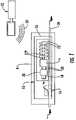
- FIG. 1is a representative schematic view of an optically addressed RFID element used with a network component according to a first embodiment of the invention, along with a source of external RF signals.
- FIG. 2is a representative schematic view of a fiber optic component according to certain aspects of the invention and including an optically addressed RFID element as in FIG. 1 , along with a source of external RF signals.
- FIG. 3is a representative schematic view of a fiber optic cable according to certain aspects of the invention and including an optically addressed RFID element as in FIG. 1 , along with a source of external RF signals.
- FIG. 4is a representative schematic view of a system according to certain aspects of the invention and including a plurality of optically addressed RFID elements, along with a plurality of sources of external RF signals.
- FIGS. 1-4show examples of optically addressed RFID elements, and of connectors, cables, cable assemblies, communications components, and systems in which such RFID elements are employed.
- the exemplary embodimentsemploy optically addressed RFID technology to allow for simple, reliable, and/or unobtrusive powering of RFID elements and/or sending RF signals to RFID elements and/or writing of data to RFID element integrated circuits. It should be understood that the embodiments disclosed herein are merely examples, each incorporating certain aspects and benefits of the present invention.
- FIG. 1shows a first example of an optically addressed RFID element 10 according to certain aspects of the invention.
- the term “optically addressed”shall include, but not be limited to, the ability of the RFID element 10 to write data to the RFID element using an optical signal, to send an RF signal to the RFID element using the optical signal, and/or to at least partially power the RFID element using the optical signal.
- RFID element 10includes an antenna 12 , an integrated circuit 14 , a schematically-represented optical tap 16 , and a transducer 18 .
- a base 20may be provided to support elements 12 - 18 .
- Source 22 of external RF signal 24such as a reader, transceiver, or the like, for use with RFID element 10 , is also illustrated.
- RFID element 10is illustrated disposed attached to a network component N adjacent an optical fiber 26 .
- Network component Nmay comprise any piece of communication equipment carrying optical signals and/or optical fibers.
- RFID element 10may, if desired, operate in some ways as does a conventional RFID element, namely by receiving external RF signal 24 from a reader, transceiver or the like via antenna 12 .
- Integrated circuit 14in electrical communication with antenna 12 via electrical connections 27 , may process the received signal and respond in any of various ways. For example, integrated circuit 14 may send an electrical signal to antenna 12 causing a return RF signal to be communicated to an RFID reader. Source 22 and/or any other RF reading devices within the range of the return RF signal can receive and process the return RF signal. Such functionality can be used for example to identify the presence, location, or status of RFID element 10 or a plurality of such elements, as desired in various applications. Information transmitted by external signal 24 may be stored in the integrated circuit or other structure on RFID element 10 , if desired, for example to assign an identification number to the RFID element, or to write data to the memory of integrated circuit 14 .
- RFID element 10may be attached to any sort of device providing an optical input, such as optical fiber 26 , or to any device part, or location, limited only by the size and shape of the RFID element and the application.
- signal power received by an RFID elementwill vary inversely with the square of distance between the RF source 24 and the RFID element 10 .
- the strength of signal available, RF signal fading, interference and noise of the source 22 and RFID element 10 , and the surrounding environment of use, etc.may also have an impact on the utilization of RFID element 10 and affect its performance and read range.
- Transducer 18 of RFID element 10is electrically connected to integrated circuit 14 via electrical connections 28 .
- a transducer circuit 30may be included between the transducer 18 and the integrated circuit 14 for processing the electrical signals generated by the transducer.
- Optical tap 16is disposed adjacent optical fiber 26 so as to re-direct a portion of an optical signal traveling through the optical fiber.
- the transducer 18is disposed near enough the optical tap 16 so that it can receive at least some of the portion of light directed out of the optical fiber 26 by the optical tap.
- the transducer 18generates an electrical signal in response based on the light it receives.
- the electrical signalis transmitted to the integrated circuit 14 via electrical connections 28 and transducer circuit 30 , if present.
- Transducer 18may comprise a photodiode, as illustrated, or a photovoltaic device, although any optical-electrical transducer and necessary processing structure and/or circuitry could be employed.
- optical tap 16is schematically illustrated in the figures for clarity.
- the optical tapfunctions to split out a portion of the light signal traveling along the optical fiber 26 without impeding the ability of the fiber to carry out its communication task.
- various structures and configurationscould comprise an optical tap 16 , as used herein.
- optical tap 16could comprise application of micro-fiber bends to optical fiber 26 .
- the fiber waveguidecould be situated proximate a tap waveguide, so that optical power is coupled from the fiber waveguide to the tap waveguide.
- the core of the optical fiber 26could be thermally expanded and/or optical gratings could be written on the core.
- Optical tap 16thus removes light out of the fiber core and into its cladding, and then outward to a photodetector or the like.
- an index-matching fluidcould be employed.
- providing a degree of surface roughness to the cladding, or providing notches or thinning via polishingcould be employed to enhance extraction of light from the fiber. Therefore, various techniques can be used, if desired, to assist in the extraction of light from the optical fiber. All such structure may be considered a portion of an optical tap, as used herein.
- the electrical signal generated by transducer 18may be transmitted to integrated circuit 14 for one or more purposes.
- the electrical signalmay be used to write data to integrated circuit 14 , including data regarding whether the optical fiber 26 has optical power propagating in it (i.e. it is active), the time of activity, or other parameters related to the optical signal. Therefore, when RFID element 10 receives the external RF signal 24 , the RFID element can responsively transmit the already-written data via a RF signal. Such data writing could also occur upon receipt of the RF signal 24 .
- the electrical signal generated by transducer 18rather than an external RF signal 24 , itself may be used to power an RF signal transmitted by the RFID element 10 . In such case no external RF signal or external power source is required for the RFID element to send a signal. If desired, the electrical signal from transducer 18 and the external RF signal 24 could both power the RFID element 10 to enable communication with the RFID reader.
- Optical tap 16can be designed so as to provide a predetermined, desired power level for RFID element 10 .
- a predetermined, desired power level for RFID element 10For example, if an optical signal being carried by optical fiber 26 has a nominal strength of about 1 mW (0 dB), a 1% tap of the signal would provide an electrical signal with a power in the range of about 10 ⁇ W.
- Such power levelis on the order necessary to power and operate an integrated circuit of an RFID element; however, further embodiments of the present invention may include a tap of any amount (or percentage) of signal/power.
- operation of the integrated circuitincludes, but is not limited to, the writing of data to the integrated circuit; the sending of RF signals; communication between multiple RFID elements; the monitoring and/or control of sensors, actuators, and the like; and so forth.
- Higher optical signal levelswould allow a smaller tap percentage.
- a passive storage devicesuch as a capacitor or trickle-fill battery could be used to store and discharge energy either one time or over a duty-cycle if the optical tap and/or optical signal strength are not powerful enough to operate an RFID integrated circuit.
- a tap that provides about 100 nW or more of optical power to the transducerwill provide suitable electrical power to perform functions related to the RFID element without causing optical signal loss to an undesirable level.
- the various characteristics of the elements abovecan be selected to meet various different operational parameters.
- further embodiments of the present inventioninclude energy storage devices, such as capacitors and batteries, to provide two non-limiting examples of energy storage devices, to enable the transducer to detect optical power propagating in the optical fiber at times when the RFID element is not being powered by external RF signals or external power sources.
- the detection by the transducermay be constant, periodic, on-demand, or at any time interval or selective instruction in order to provide certain desired information about the presence, power level, or other parameters of the optical signal.
- the transducercomprises one or more photodiodes having a sensitivity about ⁇ 40 dBm for measuring the optical signals in a fiber within a time period of about 100 msec to about 500 msec with such measurements taken at predetermined or selected intervals, such as once a minute to provide a non-limiting example.
- Still further embodiments of the present inventioncomprise alternative transducers and/or alternative energy storage devices in order to detect optical power propagating in the optical fiber at times when the RFID element is not being powered by external RF signals or external power sources.
- certain embodiments of the present inventionutilize the optical signal to communicate RF signal data to one or more RFID elements in the communications system.
- the optical signalincludes encoded RF modulated data that can be written to the integrated circuit of the RFID element and/or directly communicated by the antenna of the RFID element.
- Still further embodiments of the present inventioncomprise alternative methods for providing data to the RFID element via the optical signal.
- certain embodiments of the present inventioninclude an optical tap arrangement that is adapted to direct a portion of the optical signal carried in both the first direction and the second direction. More specifically, some of these embodiments include an optical tap that comprises a first optical tap adapted to direct a portion of the optical signal carried in the first direction and a second optical tap adapted to direct a portion of the optical signal carried in the second direction.
- other of these embodimentsinclude an optical directional coupler that is adapted to direct a portion of the optical signal carried in both the first direction and the second direction to a single transducer 18 that is in electrical communication with the RFID integrated circuit 14 .
- Still further embodiments of the present inventioninclude alternative optical taps to enable the transducer to be in optical communications with optical signals carried in two directions along the optical fiber.
- FIG. 2shows a fiber optic component 140 incorporating an optically addressed RFID element 110 similar to element 10 above. Operation of RFID element 110 is similar to that described above.
- Optical tap 116directs a portion of the optical signal passing through optical fiber 126 to transducer 118 generating an electrical signal transmitted through electrical connections 128 to integrated circuit 114 .
- the electrical signalmay cause antenna 112 to communicate an RF signal or may merely write information to the integrated circuit 114 or may provide sufficient power to operate the integrated circuit 114 enabling communication over a longer range between the RFID element 110 and the RFID reader. All options and modifications discussed above may be employed, as relevant to a connector.
- Component 140may be any type of fiber optic device, such as a connector of optical fibers, or a transmitter, or a receiver, or a WDM multiplexer, or a cable assembly, or any other device used as part of a fiber optic system. As shown for illustrative purposes only, component 140 includes a housing 142 connected to an end 144 of optical fiber 126 . Component 140 also may include a termination ferrule 148 . Component 140 may comprise any suitable type of component design, whether for a single or multiple fiber cable, and no limitation on type or configuration of component should be implied.
- Integrated circuit 114may include stored information such as serial number, type of component, cable type, manufacturer, manufacturing date, installation date, location, lot number, performance parameters (such as attenuation measured during installation), identification of what is at other end of the cable, etc. Such information could be preloaded on integrated circuit 114 at manufacture or upon installation via source 122 . Any of this information or other information may serve as identifying indicia for component 140 that may be assigned or polled by an RF source and/or reader. Further, various types of information can be determined and written to integrated circuit 114 , such as line status, time of transmission or ceasing of transmission, or any parameters discernable from the optical signal, with use of integrated circuit 114 and/or transducer circuit 130 . Therefore, the types of information that can be determined, written, stored, and/or transmitted using the structures disclosed herein are limited only by the application in which the structures are employed.
- FIG. 3shows an embodiment in which an optically addressed RFID element 210 is attached to a fiber optic cable 250 at a position spaced from either end of the cable.
- multiple optically addressed RFID elements 210(similar to element 10 above, with similar reference numerals) are employed at spaced intervals.
- Optically addressed RIFD element 210may operate as described above.
- use of a plurality of such RFID elements 210 located along a given fiber optic cable 250 at spaced intervalscan provide the added benefit of tracing an optical signal along a cable spanning long distances, or in detecting a break 252 in the cable.
- a disconnection between cables or network componentscan be detected and localized by identifying which RFID elements indicate that power is propagating and which RFID elements indicate that no power is propagating. This information determines how far along a signal path the optical signal may be detected by the plurality of RFID elements.
- a section of the cable 250may need to be replaced by the optically addressed RFID element 210 .
- Cable 250is illustrated as having a single optical fiber 226 exposed adjacent optical tap 216 . If desired, a single optical tap structure may be configured to direct optical signals from more than one fiber within a cable. Also, multiple optically addressed RFID elements 210 may be employed at a given location along a multi-fiber cable, one per fiber. Cable 250 may also have a connector as in FIG. 2 attached at one or both ends, if desired. Thus, the structures of FIG. 3 should be considered illustrative only.
- FIG. 4shows a representative system 300 having multiple optically addressd RFID elements 310 functioning as signaling devices.
- System 300includes customer premises 302 , a LEC central office 304 , a remote central office 306 , and a plurality of external RF signal sources 322 , 322 b , 322 c , which may comprise readers for sending and receiving signals 324 .
- Sources 322 and 322 care fixed in location, and source 322 b is mobile, for example hand-held.
- Each optically addressed RFID element 310can tap the associated optical fiber signal to provide an optical signal, if desired, to each RFID element.
- each RFID element 310could continuously or periodically be read by a nearby RFID reader, confirming whether the associated optical fiber is active and/or provide information regarding or carried by the optical signal.
- the respective integrated circuits and antennascould be powered via the optical taps.
- the optical tapscould simply be used to write data to the integrated circuits for reading via receipt of external RF signals 324 and responsive transmissions. It should be understood that combinations of optically addressed RFID elements and non-optically addressed RFID elements could be used in such a system, or with any of the devices within the system or discussed above.
- various identifying indiciamay be assigned to various network components for use by an RF system.
- the identifying indiciamay be preprogrammed into the integrated circuit chip within the RFID element and/or it may be assigned or modified at installation and stored in the integrated circuit chip.
- the technicianmay thus identify all connectors manufactured on a certain date, or a certain type, installed on a certain date, that are fully connected, that are carrying signal, etc.
- Other inputs to the integrated circuitare also possible, such as temperature sensors, humidity sensors, etc., which can also serve as identifying indicia. Additional purposes and applications for use of the optically addressed RFID element within optical networks are also available.
Landscapes
- Physics & Mathematics (AREA)
- General Physics & Mathematics (AREA)
- Optics & Photonics (AREA)
- Electromagnetism (AREA)
- Engineering & Computer Science (AREA)
- Computer Networks & Wireless Communication (AREA)
- Signal Processing (AREA)
- Optical Couplings Of Light Guides (AREA)
- Near-Field Transmission Systems (AREA)
- Optical Communication System (AREA)
Abstract
Description
Claims (45)
Priority Applications (8)
| Application Number | Priority Date | Filing Date | Title |
|---|---|---|---|
| US11/716,414US7547150B2 (en) | 2007-03-09 | 2007-03-09 | Optically addressed RFID elements |
| CA002680269ACA2680269A1 (en) | 2007-03-09 | 2008-03-07 | Optically addressed rfid elements |
| CN200880014483ACN101681005A (en) | 2007-03-09 | 2008-03-07 | Optically addressed RFID element |
| PCT/US2008/003100WO2008112171A1 (en) | 2007-03-09 | 2008-03-07 | Optically addressed rfid elements |
| JP2009553593AJP2010521032A (en) | 2007-03-09 | 2008-03-07 | Optical address RFID element |
| MX2009009675AMX2009009675A (en) | 2007-03-09 | 2008-03-07 | Optically addressed rfid elements. |
| EP08726609AEP2130076A1 (en) | 2007-03-09 | 2008-03-07 | Optically addressed rfid elements |
| JP2013140420AJP2013218729A (en) | 2007-03-09 | 2013-07-04 | Passive rfid elements, and components and communication systems including passive rfid elements |
Applications Claiming Priority (1)
| Application Number | Priority Date | Filing Date | Title |
|---|---|---|---|
| US11/716,414US7547150B2 (en) | 2007-03-09 | 2007-03-09 | Optically addressed RFID elements |
Publications (2)
| Publication Number | Publication Date |
|---|---|
| US20080218355A1 US20080218355A1 (en) | 2008-09-11 |
| US7547150B2true US7547150B2 (en) | 2009-06-16 |
Family
ID=39591027
Family Applications (1)
| Application Number | Title | Priority Date | Filing Date |
|---|---|---|---|
| US11/716,414ActiveUS7547150B2 (en) | 2007-03-09 | 2007-03-09 | Optically addressed RFID elements |
Country Status (7)
| Country | Link |
|---|---|
| US (1) | US7547150B2 (en) |
| EP (1) | EP2130076A1 (en) |
| JP (2) | JP2010521032A (en) |
| CN (1) | CN101681005A (en) |
| CA (1) | CA2680269A1 (en) |
| MX (1) | MX2009009675A (en) |
| WO (1) | WO2008112171A1 (en) |
Cited By (20)
| Publication number | Priority date | Publication date | Assignee | Title |
|---|---|---|---|---|
| US20090275216A1 (en)* | 2005-08-26 | 2009-11-05 | Panduit Corp. | Patch Field Documentation and Revision Systems |
| US20100080554A1 (en)* | 2008-09-30 | 2010-04-01 | Aguren Jerry G | Fiber Optic Cable Diagnostics Using Digital Modulation |
| US20100220766A1 (en)* | 2009-01-15 | 2010-09-02 | Daniel Burgard | Wireless Temperature Profiling System |
| US20130039624A1 (en)* | 2010-04-29 | 2013-02-14 | Christopher Briand Scherer | Networking Cable Tracer System |
| US8991690B2 (en) | 2012-11-16 | 2015-03-31 | Tyco Electronics Uk Ltd. | System and method for providing power and communication link for RFID managed connectivity using removable module |
| US9041255B2 (en) | 2011-07-22 | 2015-05-26 | Moon J. Kim | High capacity electronic switch |
| EP2887566A1 (en) | 2013-12-23 | 2015-06-24 | Telefonica S.A. | An optical distribution system, a splicing handheld device, a kit for an optical distribution system and a method for the construction and managing of an optical distribution system |
| US9111249B2 (en) | 2012-02-14 | 2015-08-18 | Tyco Electronics Uk Ltd | Physical layer management (PLM) system for use with an optical distribution frame using RFID antennas with localized fields |
| US9407510B2 (en) | 2013-09-04 | 2016-08-02 | Commscope Technologies Llc | Physical layer system with support for multiple active work orders and/or multiple active technicians |
| US20170176696A1 (en)* | 2014-02-11 | 2017-06-22 | Rax Connect Ltd. | Wireless non-intrusive remote monitoring optical connection apparatus utilizing rft photo-detector |
| US9810859B2 (en) | 2013-08-21 | 2017-11-07 | Mertek Industries, Llc | Traceable networking cables with remote-released connectors |
| US9995883B2 (en)* | 2014-03-26 | 2018-06-12 | Commscope Technologies Llc | Optical adapter module with managed connectivity |
| US10050389B2 (en) | 2013-01-18 | 2018-08-14 | Mertek Industries, Llc | Field-terminable traceable cables, components, kits, and methods |
| US10972182B1 (en) | 2020-09-08 | 2021-04-06 | International Business Machines Corporation | Electronically adjustable attenuation wrap plug |
| US11113642B2 (en) | 2012-09-27 | 2021-09-07 | Commscope Connectivity Uk Limited | Mobile application for assisting a technician in carrying out an electronic work order |
| US11295135B2 (en) | 2020-05-29 | 2022-04-05 | Corning Research & Development Corporation | Asset tracking of communication equipment via mixed reality based labeling |
| US11374808B2 (en) | 2020-05-29 | 2022-06-28 | Corning Research & Development Corporation | Automated logging of patching operations via mixed reality based labeling |
| WO2023038520A1 (en) | 2021-09-08 | 2023-03-16 | Terrasens B.V. | Position detection element for an optical cable, device for transmitting an optical signal to a position detection element on an optical cable, system and method for locating a non-visible optical cable |
| US11689247B2 (en) | 2019-01-16 | 2023-06-27 | Mertek Industries, Llc | Patch cord including wireless components |
| US12300943B2 (en) | 2019-09-30 | 2025-05-13 | Mertek Industries, Llc | Patch panel traceable networking system |
Families Citing this family (18)
| Publication number | Priority date | Publication date | Assignee | Title |
|---|---|---|---|---|
| DE102007017967A1 (en)* | 2007-04-10 | 2008-10-16 | Lapp Engineering & Co. | electric wire |
| DE102007017964A1 (en)* | 2007-04-10 | 2008-10-23 | Lapp Engineering & Co. | electric wire |
| DE102007017965A1 (en)* | 2007-04-10 | 2008-11-06 | Lapp Engineering & Co. | electric wire |
| US7920764B2 (en)* | 2007-05-04 | 2011-04-05 | Anthony Stephen Kewitsch | Electrically traceable and identifiable fiber optic cables and connectors |
| DE102007024212A1 (en)* | 2007-05-15 | 2008-11-20 | Lapp Engineering & Co. | electric wire |
| DE102007036948A1 (en)* | 2007-07-19 | 2009-01-22 | Lapp Engineering & Co. | Cable receiving unit |
| US7940182B2 (en)* | 2008-04-30 | 2011-05-10 | Alcatel Lucent | RFID encoding for identifying system interconnect cables |
| JP5463646B2 (en)* | 2008-10-08 | 2014-04-09 | 日立化成株式会社 | Optical module |
| US8830698B2 (en)* | 2009-02-09 | 2014-09-09 | InTech Defense, LLC. | Methods and devices for reducing communication and power signal leakages from filter assemblies |
| CN101995612B (en) | 2009-08-25 | 2012-12-12 | 华为技术有限公司 | Method, device and system for detecting jump fiber connecting state |
| DE102011078359A1 (en)* | 2011-06-29 | 2013-01-03 | Trumpf Werkzeugmaschinen Gmbh + Co. Kg | Optical element of a laser material processing machine |
| CN102511134B (en)* | 2011-11-08 | 2014-06-11 | 华为技术有限公司 | Optical fiber identification method, optical line terminal and identification system |
| US10530473B2 (en)* | 2016-02-04 | 2020-01-07 | CommScope Connectivity Belgium BVBA | Apparatus for monitoring fiber signal traffic at a fiber connector |
| US10477627B2 (en)* | 2017-03-28 | 2019-11-12 | Inductive Intelligence, Llc | Smart packages systems and methods |
| DE102017209696A1 (en)* | 2017-06-08 | 2018-12-13 | Trumpf Laser Gmbh | Protective glass with transponder and installation aid and associated laser tool |
| CN108665030A (en)* | 2018-05-11 | 2018-10-16 | 上海宜链物联网有限公司 | A kind of optical fiber pairing detecting system and method based on half active RFID |
| CN111447513A (en)* | 2020-03-18 | 2020-07-24 | 深圳市普威技术有限公司 | Optical energy collection device, PON communication system and optical energy collection method |
| EP4444154A1 (en)* | 2021-12-08 | 2024-10-16 | Thomas Newton | Systems and methods for data communication via a light cable |
Citations (205)
| Publication number | Priority date | Publication date | Assignee | Title |
|---|---|---|---|---|
| US3052842A (en) | 1959-10-15 | 1962-09-04 | Lockheed Aircraft Corp | Patchcord connection aid and checking system |
| US3609742A (en) | 1969-02-07 | 1971-09-28 | Hugh D Burdick | Property security system |
| US4200862A (en) | 1977-01-07 | 1980-04-29 | Pico Electronics Limited | Appliance control |
| US4418333A (en) | 1981-06-08 | 1983-11-29 | Pittway Corporation | Appliance control system |
| US4630886A (en) | 1984-04-16 | 1986-12-23 | At&T Bell Laboratories | Lightguide distributing unit |
| US4889977A (en) | 1987-12-21 | 1989-12-26 | Southwestern Bell Telephone Company | Method of identifying the disposition of plug-in units at a warehouse |
| US4915639A (en) | 1988-11-08 | 1990-04-10 | B.A.S.E.C. Industries, Ltd. | "Smart" AC receptacle and complementary plug |
| US4968929A (en) | 1987-04-18 | 1990-11-06 | Heidelberger Druckmaschinen Ag | Plug connector coding system for electric cables |
| JPH03242795A (en) | 1990-02-21 | 1991-10-29 | Sekisui Chem Co Ltd | Power supply plug engagement detector |
| JPH04174406A (en) | 1990-08-03 | 1992-06-22 | Nippon Telegr & Teleph Corp <Ntt> | Connector with memory element |
| US5337400A (en) | 1992-10-28 | 1994-08-09 | Northern Telecom Limited | Distribution frame and optical connector holder combination |
| US5353367A (en) | 1993-11-29 | 1994-10-04 | Northern Telecom Limited | Distribution frame and optical connector holder combination |
| US5394503A (en) | 1993-10-08 | 1995-02-28 | Data Switch Corporation | Optical fiber connection monitoring apparatus, patch panel control system and method of using same |
| US5448675A (en) | 1994-06-09 | 1995-09-05 | At&T Ipm Corp. | Telecommunications distribution frame with tracing |
| US5461693A (en) | 1994-07-14 | 1995-10-24 | At&T Ipm Corp. | Optical fiber distribution frame with fiber testing |
| US5473715A (en) | 1994-05-03 | 1995-12-05 | Methode Electronics, Inc. | Hybrid fiber optic/electrical connector |
| US5483467A (en) | 1992-06-10 | 1996-01-09 | Rit Technologies, Ltd. | Patching panel scanner |
| US5528222A (en) | 1994-09-09 | 1996-06-18 | International Business Machines Corporation | Radio frequency circuit and memory in thin flexible package |
| US5692925A (en) | 1986-07-23 | 1997-12-02 | Virginia Patent Development Corporation | Modular plug comprising circuit elements |
| US5764043A (en) | 1996-12-20 | 1998-06-09 | Siecor Corporation | Traceable patch cord and connector assembly and method for locating patch cord ends |
| US5821510A (en) | 1994-12-22 | 1998-10-13 | Lucent Technologies Inc. | Labeling and tracing system for jumper used in an exchange |
| US5847557A (en) | 1997-06-06 | 1998-12-08 | Fincher; William C. | Wire pair identification method |
| US5854824A (en) | 1994-09-04 | 1998-12-29 | Rit Technologies Ltd. | Connectivity scanner |
| US5859719A (en) | 1996-10-15 | 1999-01-12 | Lucent Technologies Inc. | Photogenerator for lightwave networks |
| US5910776A (en) | 1994-10-24 | 1999-06-08 | Id Technologies, Inc. | Method and apparatus for identifying locating or monitoring equipment or other objects |
| US5914862A (en) | 1995-05-19 | 1999-06-22 | Kasten Chase Applied Research Limited | Radio frequency identification tag |
| US5995006A (en) | 1995-09-05 | 1999-11-30 | Intermec Ip Corp. | Radio frequency tag |
| US5999400A (en) | 1998-11-30 | 1999-12-07 | Berg Technology, Inc. | Modular plug with electronic components |
| US6002331A (en) | 1998-07-20 | 1999-12-14 | Laor; Herzel | Method and apparatus for identifying and tracking connections of communication lines |
| US6025725A (en) | 1996-12-05 | 2000-02-15 | Massachusetts Institute Of Technology | Electrically active resonant structures for wireless monitoring and control |
| US6100804A (en) | 1998-10-29 | 2000-08-08 | Intecmec Ip Corp. | Radio frequency identification system |
| US6118379A (en) | 1997-12-31 | 2000-09-12 | Intermec Ip Corp. | Radio frequency identification transponder having a spiral antenna |
| US6126610A (en) | 1997-11-03 | 2000-10-03 | Novametrix Medical Systems, Inc. | Pneumatic connector with encoding |
| US6127929A (en) | 1997-12-23 | 2000-10-03 | Em Microelectronic-Marin Sa | Transponder for half-duplex communication |
| US6133835A (en) | 1997-12-05 | 2000-10-17 | U.S. Philips Corporation | Identification transponder |
| DE19920452A1 (en) | 1999-05-04 | 2000-11-30 | Siemens Ag | Optical connector for optical communications system has reduced probability of faulty configuration by network management system |
| US6164551A (en) | 1997-10-29 | 2000-12-26 | Meto International Gmbh | Radio frequency identification transponder having non-encapsulated IC chip |
| US6222975B1 (en) | 1998-12-11 | 2001-04-24 | Lucent Technologies, Inc. | System and method for detecting and reporting the use of optical fibers in fiber optic cables |
| US6222908B1 (en) | 1999-09-23 | 2001-04-24 | Avaya Technology Corp. | Method and device for identifying a specific patch cord connector as it is introduced into, or removed from, a telecommunications patch system |
| US6232870B1 (en) | 1998-08-14 | 2001-05-15 | 3M Innovative Properties Company | Applications for radio frequency identification systems |
| DE19841738C2 (en) | 1998-08-26 | 2001-05-17 | Ifam Ingenieurbuero Fuer Appli | Switch socket or mobile socket unit |
| US6234830B1 (en) | 1999-02-10 | 2001-05-22 | Avaya Technology Corp. | Tracing interface module for patch cords in a telecommunications system |
| US6243654B1 (en) | 1997-10-07 | 2001-06-05 | Telemonitor, Inc. | Transducer assembly with smart connector |
| US6285293B1 (en) | 1999-02-10 | 2001-09-04 | Avaya Technology Corp. | System and method for addressing and tracing patch cords in a dedicated telecommunications system |
| US6298255B1 (en) | 1999-06-09 | 2001-10-02 | Aspect Medical Systems, Inc. | Smart electrophysiological sensor system with automatic authentication and validation and an interface for a smart electrophysiological sensor system |
| US6330307B1 (en) | 1999-02-10 | 2001-12-11 | Avaya Technology Corp. | Display panel overlay structure and method for tracing interface modules in a telecommunications patch system |
| US6350148B1 (en) | 1999-02-10 | 2002-02-26 | Avaya Technology Corp. | Method and device for detecting the presence of a patch cord connector in a telecommunications patch system |
| US6368155B1 (en) | 1999-07-16 | 2002-04-09 | Molex Incorporated | Intelligent sensing connectors |
| US6378111B1 (en) | 1997-11-11 | 2002-04-23 | Wolfgang Brenner | Method for management and documentation of contact points of a wiring network |
| US6375362B1 (en) | 1999-05-04 | 2002-04-23 | Siemens Aktiengesellschaft | Optical plug-type connection |
| US20020071394A1 (en) | 1997-11-17 | 2002-06-13 | Adc Telecommunications, Inc. | System and method for electronically identifying connections of a cross-connect system |
| US20020086584A1 (en) | 2000-12-30 | 2002-07-04 | Liu Yu Min | Electrical connector having built-in electrical devices |
| US20020092347A1 (en) | 2001-01-17 | 2002-07-18 | Niekerk Jan Van | Radio frequency identification tag tire inflation pressure monitoring and location determining method and apparatus |
| US6424710B1 (en) | 1999-02-10 | 2002-07-23 | Avaya Technology Corp. | Method and device for detecting the presence of a patch cord connector in a telecommunications patch system using passive detection sensors |
| US6424263B1 (en) | 2000-12-01 | 2002-07-23 | Microchip Technology Incorporated | Radio frequency identification tag on a single layer substrate |
| US6424315B1 (en) | 2000-08-02 | 2002-07-23 | Amkor Technology, Inc. | Semiconductor chip having a radio-frequency identification transceiver |
| GB2371211A (en) | 2000-11-03 | 2002-07-24 | Premark Feg Llc | Atmospheric steamer with baffles and sensor |
| JP2002264617A (en) | 2001-03-07 | 2002-09-18 | Hanex Co Ltd | Structure for installing rfid tag on tire |
| US6469404B1 (en) | 1997-11-14 | 2002-10-22 | Iws International Inc. | Intelligent control system for current distribution in a vehicle |
| US6496382B1 (en) | 1995-05-19 | 2002-12-17 | Kasten Chase Applied Research Limited | Radio frequency identification tag |
| US20030021580A1 (en) | 2001-07-18 | 2003-01-30 | Photoris, Inc. | Method and apparatus for coupling terminal equipment to a node in an optical communications network |
| US6522737B1 (en) | 1999-02-10 | 2003-02-18 | Avaya Technology Corp. | System and method of operation for a telecommunications patch system |
| US6522308B1 (en) | 2000-01-03 | 2003-02-18 | Ask S.A. | Variable capacitance coupling antenna |
| US20030061393A1 (en) | 2001-09-21 | 2003-03-27 | Frank Steegmans | System and method for improving the management of information in networks by disposing machine accessible information tags along the interconnection means |
| JP2003148653A (en) | 2001-11-08 | 2003-05-21 | Furukawa Electric Co Ltd:The | Long body for signs |
| US6574586B1 (en) | 1999-04-06 | 2003-06-03 | Itracs Corporation | System for monitoring connection pattern of data ports |
| JP2003172827A (en) | 2001-12-06 | 2003-06-20 | Japan Recom Ltd | Closure for switching optical cable connection |
| US20030154273A1 (en) | 2002-01-30 | 2003-08-14 | Caveney Jack E. | Systems and methods for documenting networks with electronic modules |
| US20030154276A1 (en) | 2002-02-14 | 2003-08-14 | Caveney Jack E. | VOIP telephone location system |
| JP2003229215A (en) | 2002-02-05 | 2003-08-15 | Hitachi Maxell Ltd | Cable connector recognition system |
| US6618022B2 (en) | 2001-07-20 | 2003-09-09 | Delta Systems, Inc. | Radio frequency powered switch |
| WO2003098175A1 (en) | 2002-05-21 | 2003-11-27 | Intelligent Devices Inc. | Method for measuring temperature using a remote, passive, calibrated rf/rfid tag including a method for calibration |
| US6684179B1 (en) | 1999-04-06 | 2004-01-27 | Itracs Corporation | System for monitoring connection pattern of data ports |
| JP2004033857A (en) | 2002-07-01 | 2004-02-05 | Sumitomo Heavy Ind Ltd | Scum scraper |
| JP2004039389A (en) | 2002-07-02 | 2004-02-05 | Hitachi Maxell Ltd | electrical plug |
| US6688910B1 (en) | 1999-02-10 | 2004-02-10 | Avaya Technology Corp. | System and method for automatic addressing of devices in a dedicated telecommunications system |
| US6693513B2 (en) | 1997-10-03 | 2004-02-17 | Micron Technology, Inc. | Wireless identification device, RFID device with push-on/push off switch, and method of manufacturing wireless identification device |
| US6696952B2 (en) | 2000-08-04 | 2004-02-24 | Hei, Inc. | Structures and assembly methods for radio-frequency-identification modules |
| US20040041714A1 (en) | 2002-05-07 | 2004-03-04 | Forster Ian J. | RFID temperature device and method |
| WO2004030154A2 (en) | 2002-09-23 | 2004-04-08 | Data-Complex E.K. | Arrangement for monitoring patch panels at distributor points in data networks |
| DE10249414A1 (en) | 2002-10-23 | 2004-05-13 | Siemens Ag | Electronic communications-compatible pluggable connector unit e.g. for product data handling, has component-specific information electronically stored by data carrier |
| JP2004142500A (en) | 2002-10-22 | 2004-05-20 | Auto Network Gijutsu Kenkyusho:Kk | Connector device |
| JP2004152543A (en) | 2002-10-29 | 2004-05-27 | Auto Network Gijutsu Kenkyusho:Kk | Connector, connector system, and vehicle antitheft system using the same |
| US20040117515A1 (en) | 2002-11-15 | 2004-06-17 | Masuyuki Sago | Distributing system |
| US20040114879A1 (en) | 2002-09-27 | 2004-06-17 | Dornier Medtech Laser Gmbh | Laser with intelligent therapeutic fiber |
| US20040149736A1 (en) | 2003-01-30 | 2004-08-05 | Thermal Solutions, Inc. | RFID-controlled smart induction range and method of cooking and heating |
| US6773306B2 (en) | 2003-01-06 | 2004-08-10 | Paul J. Plishner | Connector having integrated circuits embedded in the connector body for making the connector a dynamic component of an electrical system having sections connected by the connector |
| US6784802B1 (en) | 1999-11-04 | 2004-08-31 | Nordx/Cdt, Inc. | Real time monitoring of cable patch panel |
| JP2004247090A (en) | 2003-02-12 | 2004-09-02 | Fujikura Ltd | Run-length body, its manufacturing method and cable |
| JP2004245963A (en) | 2003-02-12 | 2004-09-02 | Fujikura Ltd | Continuous body provided with RFID, method for manufacturing the same, and optical fiber cable using continuous body |
| EP1455550A2 (en) | 2003-03-05 | 2004-09-08 | Sirti S.p.A. | Network mapping system |
| JP2004264901A (en) | 2003-02-12 | 2004-09-24 | Fujikura Ltd | Run-length body, its manufacturing method and cable |
| JP2004265624A (en) | 2003-02-12 | 2004-09-24 | Fujikura Ltd | Struts and cables |
| US6808116B1 (en) | 2002-05-29 | 2004-10-26 | At&T Corp. | Fiber jumpers with data storage method and apparatus |
| JP2004317737A (en) | 2003-04-15 | 2004-11-11 | Fujikura Ltd | MT connector, clamp member used in MT connector, and optical fiber management method using MT connector |
| US6829427B1 (en) | 2000-10-24 | 2004-12-07 | Biolase Technology, Inc. | Fiber detector apparatus and related methods |
| JP2004349184A (en) | 2003-05-26 | 2004-12-09 | Oki Electric Cable Co Ltd | Connection management system for cable with connector using rfid tag and jack component |
| US6831443B2 (en) | 2001-10-30 | 2004-12-14 | Primax Electronics, Ltd. | Power adapter assembly for portable electrical device |
| US20040253874A1 (en) | 2003-01-15 | 2004-12-16 | Plishner Paul J. | Connector or other circuit element having an indirectly coupled integrated circuit |
| JP2005018175A (en) | 2003-06-24 | 2005-01-20 | Ritsumeikan | Sensor system |
| US6846115B1 (en) | 2001-01-29 | 2005-01-25 | Jds Uniphase Corporation | Methods, apparatus, and systems of fiber optic modules, elastomeric connections, and retention mechanisms therefor |
| US6847856B1 (en) | 2003-08-29 | 2005-01-25 | Lucent Technologies Inc. | Method for determining juxtaposition of physical components with use of RFID tags |
| US6857897B2 (en) | 2003-04-29 | 2005-02-22 | Hewlett-Packard Development Company, L.P. | Remote cable assist |
| JP2005050581A (en) | 2003-07-30 | 2005-02-24 | Seiko Epson Corp | Power cord, power cord inspection device and power cord inspection method |
| US20050052287A1 (en) | 2001-09-13 | 2005-03-10 | Whitesmith Howard William | Wireless communication system |
| US20050052174A1 (en) | 2003-09-05 | 2005-03-10 | Angelo Deborah A. | Traceable patch cable and connector assembly and method for identifying patch cable ends |
| US6871156B2 (en) | 2003-04-30 | 2005-03-22 | The Boeing Company | Smart connector patch panel |
| JP2005084162A (en) | 2003-09-05 | 2005-03-31 | Tokyo Tsushinki Kogyo Kk | Wiring management apparatus |
| US20050068179A1 (en) | 2003-09-30 | 2005-03-31 | Roesner Bruce B. | Distributed RF coupled system |
| JP2005086901A (en) | 2003-09-08 | 2005-03-31 | Tokyo Tsushinki Kogyo Kk | Wiring control system |
| JP2005092107A (en) | 2003-09-19 | 2005-04-07 | Tokyo Tsushinki Kogyo Kk | Management system of transmission component using connector plug with memory |
| JP2005087135A (en) | 2003-09-18 | 2005-04-07 | Hitachi Plant Eng & Constr Co Ltd | Method and apparatus for measuring food cooking history |
| US20050076982A1 (en) | 2003-10-09 | 2005-04-14 | Metcalf Arthur Richard | Post patch assembly for mounting devices in a tire interior |
| US6888996B2 (en) | 2003-04-28 | 2005-05-03 | Richard Hwang | Fiber optic cable identification kit and its method |
| US20050093677A1 (en) | 2003-11-04 | 2005-05-05 | Forster Ian J. | RFID tag with enhanced readability |
| US6898368B2 (en) | 2002-09-13 | 2005-05-24 | Fitel Usa Corp. | Adapter systems for dynamically updating information related to a network and methods for developing the adapter systems |
| JP2005134125A (en) | 2003-10-28 | 2005-05-26 | Mitsubishi Materials Corp | Tire pressure measurement means and rfid system using the same means |
| US20050111491A1 (en) | 2003-10-23 | 2005-05-26 | Panduit Corporation | System to guide and monitor the installation and revision of network cabling of an active jack network |
| US6902433B1 (en) | 1999-02-23 | 2005-06-07 | Matsushita Electric Works, Ltd. | Connector receptacle |
| US6915050B2 (en) | 2003-02-12 | 2005-07-05 | Fujikura Ltd. | Identification member in slots in the core of an optical fiber cable |
| US6917763B1 (en) | 2002-03-05 | 2005-07-12 | Nortel Networks Limited | Technique for verifying fiber connectivity in a photonic network |
| WO2005069203A2 (en) | 2004-01-09 | 2005-07-28 | United Parcel Service Of America, Inc. | System, method and apparatus for capturing telematics data with an active rfid tag |
| US6924997B2 (en) | 2000-09-25 | 2005-08-02 | Symetrix Corporation | Ferroelectric memory and method of operating same |
| JP2005216698A (en) | 2004-01-30 | 2005-08-11 | Tokyo Tsushinki Kogyo Kk | Wiring connection management system |
| US20050215119A1 (en) | 2004-02-20 | 2005-09-29 | Hitachi Maxell, Ltd. | Adapter panel, electronic equipment, and cable connector identification system |
| US20050224585A1 (en) | 2004-04-02 | 2005-10-13 | Durrant Richard C E | Radio frequency identification of a connector by a patch panel or other similar structure |
| JP2005302403A (en) | 2004-04-08 | 2005-10-27 | Auto Network Gijutsu Kenkyusho:Kk | Connector device with control function, address setting system, and address setting method |
| US6961675B2 (en) | 2000-03-14 | 2005-11-01 | Itracs Corporation | System for monitoring connection pattern of data ports |
| JP2005315980A (en) | 2004-04-27 | 2005-11-10 | Tokyo Tsushinki Kogyo Kk | Optical wiring searching system |
| US20050259930A1 (en) | 2004-05-24 | 2005-11-24 | Elkins Robert B Ii | Methods and apparatus for facilitating cable locating |
| US6968994B1 (en) | 2004-07-06 | 2005-11-29 | Nortel Networks Ltd | RF-ID for cable management and port identification |
| US6973243B2 (en) | 2003-02-13 | 2005-12-06 | Fujikura Ltd. | Cable |
| US6971895B2 (en) | 2002-11-15 | 2005-12-06 | Tokyo Communication Equipment Mfg Co., Ltd. | Connector adapter with memory function unit |
| JP2005339983A (en) | 2004-05-27 | 2005-12-08 | Fujitsu Ltd | Connector identification / connection management device |
| US20050280511A1 (en) | 2004-06-17 | 2005-12-22 | Kazuyuki Yokoyama | IC tag module, electronic device, information communication system, and communication control method for an IC tag module |
| US6999028B2 (en) | 2003-12-23 | 2006-02-14 | 3M Innovative Properties Company | Ultra high frequency radio frequency identification tag |
| JP2006054118A (en) | 2004-08-12 | 2006-02-23 | Tokyo Tsushinki Kogyo Kk | Wiring support system |
| US20060044148A1 (en) | 2004-09-02 | 2006-03-02 | International Business Machines Corporation | On-demand system for connector access independent of ambient light level |
| US7016726B1 (en) | 2000-05-17 | 2006-03-21 | Koninklijke Philips Electronics N.V. | Smart medical connector system and method of use |
| US7014100B2 (en) | 2001-04-27 | 2006-03-21 | Marathon Oil Company | Process and assembly for identifying and tracking assets |
| US7024089B2 (en) | 2004-07-26 | 2006-04-04 | Sbc Knowledge Ventures, L.P. | Fiber distribution frame arrangement having a centralized controller which universally controls and monitors access to fiber distribution frames |
| US7028087B2 (en) | 2001-02-23 | 2006-04-11 | Panduit Corp. | Network documentation system with electronic modules |
| US7027704B2 (en) | 2001-05-30 | 2006-04-11 | Ccs Technology, Inc. | Optical distribution device and light waveguide connector cable |
| US7028202B2 (en) | 2002-07-24 | 2006-04-11 | Hewlett-Packard Development Company, L.P. | Power adapter identification |
| US7046899B2 (en) | 2004-03-02 | 2006-05-16 | Furukawa Electric North America, Inc. | Universal apparatus for incorporating intelligence into an optical fiber distribution frame |
| US7062139B2 (en) | 2003-12-03 | 2006-06-13 | Prime Optical Fiber Corporation | Core of an optical patch cord and an optical signal transmission system using the same and a method for preparing the same |
| US7069345B2 (en) | 2001-05-09 | 2006-06-27 | Koninklijke Philips Electronics N.V. | Device identification and control in network environment |
| US20060148279A1 (en) | 2004-12-06 | 2006-07-06 | Commscope Solutions Properties, Llc | Telecommunications patching system that utilizes RFID tags to detect and identify patch cord interconnections |
| US7080945B2 (en) | 2002-09-13 | 2006-07-25 | Fitel Usa Corporation | Connector systems for dynamically updating information related to a network and methods for developing the connector systems |
| US7081808B2 (en) | 2002-09-13 | 2006-07-25 | Fitel Usa Corp. | Self-registration systems and methods for dynamically updating information related to a network |
| US20060166546A1 (en) | 2005-01-26 | 2006-07-27 | Minoru Ashizawa | Connector device, apparatus and method for acquiring data of electrical device using the connector device, and control system for electrical device |
| US7096077B2 (en) | 2001-06-28 | 2006-08-22 | Renishaw Plc | Tool identification |
| US7102520B2 (en) | 2002-12-31 | 2006-09-05 | Avery Dennison Corporation | RFID device and method of forming |
| JP2006245983A (en) | 2005-03-03 | 2006-09-14 | Teruya:Kk | Plug and outlet for power supply with communication function |
| JP2006279650A (en) | 2005-03-30 | 2006-10-12 | Kddi Corp | Power line communication management method and system, and power outlet management method and apparatus |
| US7123810B2 (en) | 2004-05-04 | 2006-10-17 | Bellsouth Intellectual Property Corporation | Optical fiber connectors with identification circuits and distribution terminals that communicate therewith |
| US20060232419A1 (en) | 2005-04-13 | 2006-10-19 | Fujitsu Limited | RFID tag and antenna arranging method |
| US20060233506A1 (en)* | 2005-04-19 | 2006-10-19 | Michael Noonan | Fiber breakout with integral connector |
| US7140782B2 (en) | 2001-12-13 | 2006-11-28 | Ccs Technology Inc. | Patch cable management system |
| US20060267778A1 (en) | 2003-03-24 | 2006-11-30 | Gengel Gleen W | RFID tags and processes for producing RFID tags |
| US20060282529A1 (en) | 2005-06-14 | 2006-12-14 | Panduit Corp. | Method and apparatus for monitoring physical network topology information |
| US7151455B2 (en) | 2004-04-30 | 2006-12-19 | Kimberly-Clark Worldwide, Inc. | Activating a data tag by load or orientation or user control |
| US7158033B2 (en) | 2004-09-01 | 2007-01-02 | Avery Dennison Corporation | RFID device with combined reactive coupler |
| US7158031B2 (en) | 1992-08-12 | 2007-01-02 | Micron Technology, Inc. | Thin, flexible, RFID label and system for use |
| US20070013487A1 (en) | 2005-07-18 | 2007-01-18 | Jan Scholtz | Digital certificate on connectors and other products using RFID tags and/or labels as well as RFID reader/interrogator |
| US20070015410A1 (en) | 2005-07-12 | 2007-01-18 | Siemon John A | Telecommunications connector with modular element |
| US7165728B2 (en) | 2004-04-02 | 2007-01-23 | Stratos International, Inc. | Radio frequency identification for transfer of component information in fiber optic testing |
| US7170393B2 (en) | 2004-03-30 | 2007-01-30 | Lucent Technologies, Inc. | Method and apparatus for the automatic determination of network cable connections using RFID tags and an antenna grid |
| US20070023525A1 (en) | 2005-07-27 | 2007-02-01 | Hae-Won Son | Open-ended two-strip meander line antenna, RFID tag using the antenna, and antenna impedance matching method thereof |
| US20070032124A1 (en) | 2005-08-08 | 2007-02-08 | Panduit Corp. | Systems and methods for detecting a patch cord end connection |
| US20070036506A1 (en) | 2004-08-09 | 2007-02-15 | Anthony Kewitsch | Fiber Optic Rotary Coupling and Devices |
| US7193422B2 (en) | 2004-01-20 | 2007-03-20 | The Siemon Company | Patch panel system |
| JP2007087849A (en) | 2005-09-26 | 2007-04-05 | Seiko Epson Corp | Outlet device |
| JP2007088957A (en) | 2005-09-26 | 2007-04-05 | Kddi Corp | Power strip |
| US7205898B2 (en) | 2004-10-04 | 2007-04-17 | Dixon Paul F | RFID tags |
| US7210858B2 (en) | 2002-01-15 | 2007-05-01 | Tokyo Communications Equipment Co., Ltd. | Optical connector with memory function |
| US7221277B2 (en) | 2004-10-05 | 2007-05-22 | Tracking Technologies, Inc. | Radio frequency identification tag and method of making the same |
| US7224278B2 (en) | 2005-10-18 | 2007-05-29 | Avery Dennison Corporation | Label with electronic components and method of making same |
| US7224280B2 (en) | 2002-12-31 | 2007-05-29 | Avery Dennison Corporation | RFID device and method of forming |
| US20070120684A1 (en) | 2005-11-18 | 2007-05-31 | Kenji Utaka | Methods for manufacturing and application of RFID built-in cable, and dedicated RFID reading systems |
| US7226217B1 (en) | 2005-11-18 | 2007-06-05 | Stratos International, Inc. | Transceiver/fiber optic connector adaptor with patch cord ID reading capability |
| US7233250B2 (en) | 2004-12-29 | 2007-06-19 | Avery Dennison Corporation | Radio frequency identification device with visual indicator |
| JP2007158993A (en) | 2005-12-08 | 2007-06-21 | Tokyo Tsushinki Kogyo Kk | Wiring management system |
| US7234944B2 (en) | 2005-08-26 | 2007-06-26 | Panduit Corp. | Patch field documentation and revision systems |
| US20070152828A1 (en) | 2005-08-31 | 2007-07-05 | Mohalik Swarup K | Methods and apparatus for tag activation |
| US7243837B2 (en) | 2004-04-02 | 2007-07-17 | Stratos International, Inc. | Media converter RFID security tag |
| JP2007189774A (en) | 2006-01-11 | 2007-07-26 | Tokyo Tsushinki Kogyo Kk | Wiring management system |
| JP2007221400A (en) | 2006-02-16 | 2007-08-30 | Tokyo Tsushinki Kogyo Kk | Wiring management system |
| US7275970B2 (en) | 2003-04-01 | 2007-10-02 | Seiko Epson Corporation | Plug error insertion prevention systems, plugs, plug insertion sections, plug control programs, contactless identification tag control programs, and plug insertion section control programs |
| US20070238343A1 (en) | 2006-03-14 | 2007-10-11 | Frank Velleca | Methods and systems to monitor physical layer connections |
| US20070236355A1 (en) | 2006-03-29 | 2007-10-11 | Flaster Michael E | Patch panel cover mounted antenna grid for use in the automatic determination of network cable connections using RFID tags |
| US20070241439A1 (en) | 2006-04-14 | 2007-10-18 | Yu-Peng Chung | RFID package structure |
| US20070247284A1 (en) | 2006-04-11 | 2007-10-25 | Martin Clifford E | Column based antenna array employing antenna field shaping for use in the automatic determination of network cable connections using RFID tags |
| US7298266B2 (en) | 2005-05-09 | 2007-11-20 | Avery Dennison | RFID communication systems and methods |
| US7297018B2 (en) | 2004-11-03 | 2007-11-20 | Panduit Corp. | Method and apparatus for patch panel patch cord documentation and revision |
| US7297028B2 (en) | 2005-12-01 | 2007-11-20 | Fujitsu Component Limited | Cable connector type transceiver module |
| US7306489B2 (en) | 2004-07-26 | 2007-12-11 | Fci Americas Technology, Inc. | Performance indicating electrical connector |
| WO2008000656A1 (en) | 2006-06-28 | 2008-01-03 | Weidmüller Interface GmbH & Co. KG | Electrical plug connector with coding |
| US7318744B2 (en) | 2005-06-21 | 2008-01-15 | Hon Hai Precision Ind. Co., Ltd. | Power connector with ID identifying member |
| US7336883B2 (en) | 2005-09-08 | 2008-02-26 | Stratos International, Inc. | Indexing optical fiber adapter |
| US7352285B2 (en) | 2004-09-03 | 2008-04-01 | Hitachi, Ltd. | IC tag mounting on a harness and harness mounting method |
| US7352289B1 (en) | 2003-09-11 | 2008-04-01 | Sun Microsystems, Inc. | System and method for detecting the connection state of a network cable connector |
| US7354298B2 (en) | 2003-09-26 | 2008-04-08 | Hellermanntyton Data Limited | Structured cabling system and patching method |
| US7356208B2 (en) | 2006-05-03 | 2008-04-08 | Biolase Technology, Inc. | Fiber detector apparatus and related methods |
| US20080106415A1 (en) | 2006-11-08 | 2008-05-08 | Macsema, Inc. | Information tag |
Family Cites Families (5)
| Publication number | Priority date | Publication date | Assignee | Title |
|---|---|---|---|---|
| JP2002156564A (en)* | 2000-09-05 | 2002-05-31 | Matsushita Electric Ind Co Ltd | Optical signal reader |
| US7583642B2 (en)* | 2002-09-10 | 2009-09-01 | Harris Corporation | Communication system providing hybrid optical/wireless communications and related methods |
| JP2006131173A (en)* | 2004-11-09 | 2006-05-25 | Railway Technical Res Inst | Train track monitoring system |
| US7388892B2 (en)* | 2004-12-17 | 2008-06-17 | Corning Incorporated | System and method for optically powering a remote network component |
| JP4675961B2 (en)* | 2005-05-02 | 2011-04-27 | 三菱電機株式会社 | Photodiode array and optical microwave transmission system receiver |
- 2007
- 2007-03-09USUS11/716,414patent/US7547150B2/enactiveActive
- 2008
- 2008-03-07CNCN200880014483Apatent/CN101681005A/enactivePending
- 2008-03-07JPJP2009553593Apatent/JP2010521032A/enactivePending
- 2008-03-07WOPCT/US2008/003100patent/WO2008112171A1/enactiveApplication Filing
- 2008-03-07MXMX2009009675Apatent/MX2009009675A/enactiveIP Right Grant
- 2008-03-07CACA002680269Apatent/CA2680269A1/ennot_activeAbandoned
- 2008-03-07EPEP08726609Apatent/EP2130076A1/ennot_activeWithdrawn
- 2013
- 2013-07-04JPJP2013140420Apatent/JP2013218729A/enactivePending
Patent Citations (222)
| Publication number | Priority date | Publication date | Assignee | Title |
|---|---|---|---|---|
| US3052842A (en) | 1959-10-15 | 1962-09-04 | Lockheed Aircraft Corp | Patchcord connection aid and checking system |
| US3609742A (en) | 1969-02-07 | 1971-09-28 | Hugh D Burdick | Property security system |
| US4200862A (en) | 1977-01-07 | 1980-04-29 | Pico Electronics Limited | Appliance control |
| US4418333A (en) | 1981-06-08 | 1983-11-29 | Pittway Corporation | Appliance control system |
| US4630886A (en) | 1984-04-16 | 1986-12-23 | At&T Bell Laboratories | Lightguide distributing unit |
| US5692925A (en) | 1986-07-23 | 1997-12-02 | Virginia Patent Development Corporation | Modular plug comprising circuit elements |
| US4968929A (en) | 1987-04-18 | 1990-11-06 | Heidelberger Druckmaschinen Ag | Plug connector coding system for electric cables |
| US4889977A (en) | 1987-12-21 | 1989-12-26 | Southwestern Bell Telephone Company | Method of identifying the disposition of plug-in units at a warehouse |
| US4915639A (en) | 1988-11-08 | 1990-04-10 | B.A.S.E.C. Industries, Ltd. | "Smart" AC receptacle and complementary plug |
| JPH03242795A (en) | 1990-02-21 | 1991-10-29 | Sekisui Chem Co Ltd | Power supply plug engagement detector |
| JPH04174406A (en) | 1990-08-03 | 1992-06-22 | Nippon Telegr & Teleph Corp <Ntt> | Connector with memory element |
| US5483467A (en) | 1992-06-10 | 1996-01-09 | Rit Technologies, Ltd. | Patching panel scanner |
| US20070290812A1 (en)* | 1992-08-12 | 2007-12-20 | Tuttle John R | Miniature Radio Frequency Transceiver |
| US7265674B2 (en) | 1992-08-12 | 2007-09-04 | Micron Technology, Inc. | Thin flexible, RFID labels, and method and apparatus for use |
| US7158031B2 (en) | 1992-08-12 | 2007-01-02 | Micron Technology, Inc. | Thin, flexible, RFID label and system for use |
| US5337400A (en) | 1992-10-28 | 1994-08-09 | Northern Telecom Limited | Distribution frame and optical connector holder combination |
| US5394503A (en) | 1993-10-08 | 1995-02-28 | Data Switch Corporation | Optical fiber connection monitoring apparatus, patch panel control system and method of using same |
| US5353367A (en) | 1993-11-29 | 1994-10-04 | Northern Telecom Limited | Distribution frame and optical connector holder combination |
| US5473715A (en) | 1994-05-03 | 1995-12-05 | Methode Electronics, Inc. | Hybrid fiber optic/electrical connector |
| US5448675A (en) | 1994-06-09 | 1995-09-05 | At&T Ipm Corp. | Telecommunications distribution frame with tracing |
| US5461693A (en) | 1994-07-14 | 1995-10-24 | At&T Ipm Corp. | Optical fiber distribution frame with fiber testing |
| US5854824A (en) | 1994-09-04 | 1998-12-29 | Rit Technologies Ltd. | Connectivity scanner |
| US5528222A (en) | 1994-09-09 | 1996-06-18 | International Business Machines Corporation | Radio frequency circuit and memory in thin flexible package |
| US5910776A (en) | 1994-10-24 | 1999-06-08 | Id Technologies, Inc. | Method and apparatus for identifying locating or monitoring equipment or other objects |
| US5821510A (en) | 1994-12-22 | 1998-10-13 | Lucent Technologies Inc. | Labeling and tracing system for jumper used in an exchange |
| US5914862A (en) | 1995-05-19 | 1999-06-22 | Kasten Chase Applied Research Limited | Radio frequency identification tag |
| US6496382B1 (en) | 1995-05-19 | 2002-12-17 | Kasten Chase Applied Research Limited | Radio frequency identification tag |
| US5995006A (en) | 1995-09-05 | 1999-11-30 | Intermec Ip Corp. | Radio frequency tag |
| US5859719A (en) | 1996-10-15 | 1999-01-12 | Lucent Technologies Inc. | Photogenerator for lightwave networks |
| US6025725A (en) | 1996-12-05 | 2000-02-15 | Massachusetts Institute Of Technology | Electrically active resonant structures for wireless monitoring and control |
| US5764043A (en) | 1996-12-20 | 1998-06-09 | Siecor Corporation | Traceable patch cord and connector assembly and method for locating patch cord ends |
| US5847557A (en) | 1997-06-06 | 1998-12-08 | Fincher; William C. | Wire pair identification method |
| US6693513B2 (en) | 1997-10-03 | 2004-02-17 | Micron Technology, Inc. | Wireless identification device, RFID device with push-on/push off switch, and method of manufacturing wireless identification device |
| US6243654B1 (en) | 1997-10-07 | 2001-06-05 | Telemonitor, Inc. | Transducer assembly with smart connector |
| US6164551A (en) | 1997-10-29 | 2000-12-26 | Meto International Gmbh | Radio frequency identification transponder having non-encapsulated IC chip |
| US6126610A (en) | 1997-11-03 | 2000-10-03 | Novametrix Medical Systems, Inc. | Pneumatic connector with encoding |
| US6378111B1 (en) | 1997-11-11 | 2002-04-23 | Wolfgang Brenner | Method for management and documentation of contact points of a wiring network |
| US6469404B1 (en) | 1997-11-14 | 2002-10-22 | Iws International Inc. | Intelligent control system for current distribution in a vehicle |
| US20020071394A1 (en) | 1997-11-17 | 2002-06-13 | Adc Telecommunications, Inc. | System and method for electronically identifying connections of a cross-connect system |
| US6133835A (en) | 1997-12-05 | 2000-10-17 | U.S. Philips Corporation | Identification transponder |
| US6127929A (en) | 1997-12-23 | 2000-10-03 | Em Microelectronic-Marin Sa | Transponder for half-duplex communication |
| US6118379A (en) | 1997-12-31 | 2000-09-12 | Intermec Ip Corp. | Radio frequency identification transponder having a spiral antenna |
| US6002331A (en) | 1998-07-20 | 1999-12-14 | Laor; Herzel | Method and apparatus for identifying and tracking connections of communication lines |
| US6232870B1 (en) | 1998-08-14 | 2001-05-15 | 3M Innovative Properties Company | Applications for radio frequency identification systems |
| DE19841738C2 (en) | 1998-08-26 | 2001-05-17 | Ifam Ingenieurbuero Fuer Appli | Switch socket or mobile socket unit |
| US6100804A (en) | 1998-10-29 | 2000-08-08 | Intecmec Ip Corp. | Radio frequency identification system |
| US5999400A (en) | 1998-11-30 | 1999-12-07 | Berg Technology, Inc. | Modular plug with electronic components |
| US6222975B1 (en) | 1998-12-11 | 2001-04-24 | Lucent Technologies, Inc. | System and method for detecting and reporting the use of optical fibers in fiber optic cables |
| US6330307B1 (en) | 1999-02-10 | 2001-12-11 | Avaya Technology Corp. | Display panel overlay structure and method for tracing interface modules in a telecommunications patch system |
| US6688910B1 (en) | 1999-02-10 | 2004-02-10 | Avaya Technology Corp. | System and method for automatic addressing of devices in a dedicated telecommunications system |
| US6350148B1 (en) | 1999-02-10 | 2002-02-26 | Avaya Technology Corp. | Method and device for detecting the presence of a patch cord connector in a telecommunications patch system |
| US6522737B1 (en) | 1999-02-10 | 2003-02-18 | Avaya Technology Corp. | System and method of operation for a telecommunications patch system |
| US6234830B1 (en) | 1999-02-10 | 2001-05-22 | Avaya Technology Corp. | Tracing interface module for patch cords in a telecommunications system |
| US6424710B1 (en) | 1999-02-10 | 2002-07-23 | Avaya Technology Corp. | Method and device for detecting the presence of a patch cord connector in a telecommunications patch system using passive detection sensors |
| US6285293B1 (en) | 1999-02-10 | 2001-09-04 | Avaya Technology Corp. | System and method for addressing and tracing patch cords in a dedicated telecommunications system |
| US6902433B1 (en) | 1999-02-23 | 2005-06-07 | Matsushita Electric Works, Ltd. | Connector receptacle |
| US7160143B2 (en) | 1999-04-06 | 2007-01-09 | Itracs Corporation | System for monitoring connection pattern of data ports |
| US6684179B1 (en) | 1999-04-06 | 2004-01-27 | Itracs Corporation | System for monitoring connection pattern of data ports |
| US6725177B2 (en) | 1999-04-06 | 2004-04-20 | Itracs Corporation | System for monitoring connection pattern of data ports |
| US6574586B1 (en) | 1999-04-06 | 2003-06-03 | Itracs Corporation | System for monitoring connection pattern of data ports |
| US6375362B1 (en) | 1999-05-04 | 2002-04-23 | Siemens Aktiengesellschaft | Optical plug-type connection |
| DE19920452A1 (en) | 1999-05-04 | 2000-11-30 | Siemens Ag | Optical connector for optical communications system has reduced probability of faulty configuration by network management system |
| US6298255B1 (en) | 1999-06-09 | 2001-10-02 | Aspect Medical Systems, Inc. | Smart electrophysiological sensor system with automatic authentication and validation and an interface for a smart electrophysiological sensor system |
| US6368155B1 (en) | 1999-07-16 | 2002-04-09 | Molex Incorporated | Intelligent sensing connectors |
| US6222908B1 (en) | 1999-09-23 | 2001-04-24 | Avaya Technology Corp. | Method and device for identifying a specific patch cord connector as it is introduced into, or removed from, a telecommunications patch system |
| US6784802B1 (en) | 1999-11-04 | 2004-08-31 | Nordx/Cdt, Inc. | Real time monitoring of cable patch panel |
| US6522308B1 (en) | 2000-01-03 | 2003-02-18 | Ask S.A. | Variable capacitance coupling antenna |
| US6961675B2 (en) | 2000-03-14 | 2005-11-01 | Itracs Corporation | System for monitoring connection pattern of data ports |
| US7016726B1 (en) | 2000-05-17 | 2006-03-21 | Koninklijke Philips Electronics N.V. | Smart medical connector system and method of use |
| US6424315B1 (en) | 2000-08-02 | 2002-07-23 | Amkor Technology, Inc. | Semiconductor chip having a radio-frequency identification transceiver |
| US6696952B2 (en) | 2000-08-04 | 2004-02-24 | Hei, Inc. | Structures and assembly methods for radio-frequency-identification modules |
| US6924997B2 (en) | 2000-09-25 | 2005-08-02 | Symetrix Corporation | Ferroelectric memory and method of operating same |
| US6829427B1 (en) | 2000-10-24 | 2004-12-07 | Biolase Technology, Inc. | Fiber detector apparatus and related methods |
| US7068912B1 (en) | 2000-10-24 | 2006-06-27 | Biolase Technology, Inc. | Fiber detector apparatus and related methods |
| US7194180B2 (en) | 2000-10-24 | 2007-03-20 | Biolase Technology, Inc. | Fiber detector apparatus and related methods |
| GB2371211A (en) | 2000-11-03 | 2002-07-24 | Premark Feg Llc | Atmospheric steamer with baffles and sensor |
| US6496113B2 (en) | 2000-12-01 | 2002-12-17 | Microchip Technology Incorporated | Radio frequency identification tag on a single layer substrate |
| US6424263B1 (en) | 2000-12-01 | 2002-07-23 | Microchip Technology Incorporated | Radio frequency identification tag on a single layer substrate |
| US20020086584A1 (en) | 2000-12-30 | 2002-07-04 | Liu Yu Min | Electrical connector having built-in electrical devices |
| US20020092347A1 (en) | 2001-01-17 | 2002-07-18 | Niekerk Jan Van | Radio frequency identification tag tire inflation pressure monitoring and location determining method and apparatus |
| US6846115B1 (en) | 2001-01-29 | 2005-01-25 | Jds Uniphase Corporation | Methods, apparatus, and systems of fiber optic modules, elastomeric connections, and retention mechanisms therefor |
| US7028087B2 (en) | 2001-02-23 | 2006-04-11 | Panduit Corp. | Network documentation system with electronic modules |
| JP2002264617A (en) | 2001-03-07 | 2002-09-18 | Hanex Co Ltd | Structure for installing rfid tag on tire |
| US7014100B2 (en) | 2001-04-27 | 2006-03-21 | Marathon Oil Company | Process and assembly for identifying and tracking assets |
| US7069345B2 (en) | 2001-05-09 | 2006-06-27 | Koninklijke Philips Electronics N.V. | Device identification and control in network environment |
| US7027704B2 (en) | 2001-05-30 | 2006-04-11 | Ccs Technology, Inc. | Optical distribution device and light waveguide connector cable |
| US7096077B2 (en) | 2001-06-28 | 2006-08-22 | Renishaw Plc | Tool identification |
| US20030021580A1 (en) | 2001-07-18 | 2003-01-30 | Photoris, Inc. | Method and apparatus for coupling terminal equipment to a node in an optical communications network |
| US6618022B2 (en) | 2001-07-20 | 2003-09-09 | Delta Systems, Inc. | Radio frequency powered switch |
| US20050052287A1 (en) | 2001-09-13 | 2005-03-10 | Whitesmith Howard William | Wireless communication system |
| US20030061393A1 (en) | 2001-09-21 | 2003-03-27 | Frank Steegmans | System and method for improving the management of information in networks by disposing machine accessible information tags along the interconnection means |
| US6831443B2 (en) | 2001-10-30 | 2004-12-14 | Primax Electronics, Ltd. | Power adapter assembly for portable electrical device |
| JP2003148653A (en) | 2001-11-08 | 2003-05-21 | Furukawa Electric Co Ltd:The | Long body for signs |
| JP2003172827A (en) | 2001-12-06 | 2003-06-20 | Japan Recom Ltd | Closure for switching optical cable connection |
| US7140782B2 (en) | 2001-12-13 | 2006-11-28 | Ccs Technology Inc. | Patch cable management system |
| US7210858B2 (en) | 2002-01-15 | 2007-05-01 | Tokyo Communications Equipment Co., Ltd. | Optical connector with memory function |
| US20030154273A1 (en) | 2002-01-30 | 2003-08-14 | Caveney Jack E. | Systems and methods for documenting networks with electronic modules |
| JP2003229215A (en) | 2002-02-05 | 2003-08-15 | Hitachi Maxell Ltd | Cable connector recognition system |
| US20030154276A1 (en) | 2002-02-14 | 2003-08-14 | Caveney Jack E. | VOIP telephone location system |
| US6917763B1 (en) | 2002-03-05 | 2005-07-12 | Nortel Networks Limited | Technique for verifying fiber connectivity in a photonic network |
| US20040041714A1 (en) | 2002-05-07 | 2004-03-04 | Forster Ian J. | RFID temperature device and method |
| WO2003098175A1 (en) | 2002-05-21 | 2003-11-27 | Intelligent Devices Inc. | Method for measuring temperature using a remote, passive, calibrated rf/rfid tag including a method for calibration |
| US6808116B1 (en) | 2002-05-29 | 2004-10-26 | At&T Corp. | Fiber jumpers with data storage method and apparatus |
| JP2004033857A (en) | 2002-07-01 | 2004-02-05 | Sumitomo Heavy Ind Ltd | Scum scraper |
| JP2004039389A (en) | 2002-07-02 | 2004-02-05 | Hitachi Maxell Ltd | electrical plug |
| US7028202B2 (en) | 2002-07-24 | 2006-04-11 | Hewlett-Packard Development Company, L.P. | Power adapter identification |
| US7081808B2 (en) | 2002-09-13 | 2006-07-25 | Fitel Usa Corp. | Self-registration systems and methods for dynamically updating information related to a network |
| US6898368B2 (en) | 2002-09-13 | 2005-05-24 | Fitel Usa Corp. | Adapter systems for dynamically updating information related to a network and methods for developing the adapter systems |
| US7080945B2 (en) | 2002-09-13 | 2006-07-25 | Fitel Usa Corporation | Connector systems for dynamically updating information related to a network and methods for developing the connector systems |
| WO2004030154A2 (en) | 2002-09-23 | 2004-04-08 | Data-Complex E.K. | Arrangement for monitoring patch panels at distributor points in data networks |
| US20040114879A1 (en) | 2002-09-27 | 2004-06-17 | Dornier Medtech Laser Gmbh | Laser with intelligent therapeutic fiber |
| JP2004142500A (en) | 2002-10-22 | 2004-05-20 | Auto Network Gijutsu Kenkyusho:Kk | Connector device |
| DE10249414A1 (en) | 2002-10-23 | 2004-05-13 | Siemens Ag | Electronic communications-compatible pluggable connector unit e.g. for product data handling, has component-specific information electronically stored by data carrier |
| JP2004152543A (en) | 2002-10-29 | 2004-05-27 | Auto Network Gijutsu Kenkyusho:Kk | Connector, connector system, and vehicle antitheft system using the same |
| US20040117515A1 (en) | 2002-11-15 | 2004-06-17 | Masuyuki Sago | Distributing system |
| US6971895B2 (en) | 2002-11-15 | 2005-12-06 | Tokyo Communication Equipment Mfg Co., Ltd. | Connector adapter with memory function unit |
| US20070216534A1 (en) | 2002-12-31 | 2007-09-20 | Ferguson Scott W | Rfid device and method of forming |
| US7224280B2 (en) | 2002-12-31 | 2007-05-29 | Avery Dennison Corporation | RFID device and method of forming |
| US7102520B2 (en) | 2002-12-31 | 2006-09-05 | Avery Dennison Corporation | RFID device and method of forming |
| US6773306B2 (en) | 2003-01-06 | 2004-08-10 | Paul J. Plishner | Connector having integrated circuits embedded in the connector body for making the connector a dynamic component of an electrical system having sections connected by the connector |
| US20040253874A1 (en) | 2003-01-15 | 2004-12-16 | Plishner Paul J. | Connector or other circuit element having an indirectly coupled integrated circuit |
| US20040149736A1 (en) | 2003-01-30 | 2004-08-05 | Thermal Solutions, Inc. | RFID-controlled smart induction range and method of cooking and heating |
| US6915050B2 (en) | 2003-02-12 | 2005-07-05 | Fujikura Ltd. | Identification member in slots in the core of an optical fiber cable |
| JP2004265624A (en) | 2003-02-12 | 2004-09-24 | Fujikura Ltd | Struts and cables |
| JP2004264901A (en) | 2003-02-12 | 2004-09-24 | Fujikura Ltd | Run-length body, its manufacturing method and cable |
| JP2004245963A (en) | 2003-02-12 | 2004-09-02 | Fujikura Ltd | Continuous body provided with RFID, method for manufacturing the same, and optical fiber cable using continuous body |
| JP2004247090A (en) | 2003-02-12 | 2004-09-02 | Fujikura Ltd | Run-length body, its manufacturing method and cable |
| US6973243B2 (en) | 2003-02-13 | 2005-12-06 | Fujikura Ltd. | Cable |
| EP1455550A2 (en) | 2003-03-05 | 2004-09-08 | Sirti S.p.A. | Network mapping system |
| US20060267778A1 (en) | 2003-03-24 | 2006-11-30 | Gengel Gleen W | RFID tags and processes for producing RFID tags |
| US7253735B2 (en) | 2003-03-24 | 2007-08-07 | Alien Technology Corporation | RFID tags and processes for producing RFID tags |
| US7275970B2 (en) | 2003-04-01 | 2007-10-02 | Seiko Epson Corporation | Plug error insertion prevention systems, plugs, plug insertion sections, plug control programs, contactless identification tag control programs, and plug insertion section control programs |
| JP2004317737A (en) | 2003-04-15 | 2004-11-11 | Fujikura Ltd | MT connector, clamp member used in MT connector, and optical fiber management method using MT connector |
| US6888996B2 (en) | 2003-04-28 | 2005-05-03 | Richard Hwang | Fiber optic cable identification kit and its method |
| US6857897B2 (en) | 2003-04-29 | 2005-02-22 | Hewlett-Packard Development Company, L.P. | Remote cable assist |
| US6871156B2 (en) | 2003-04-30 | 2005-03-22 | The Boeing Company | Smart connector patch panel |
| JP2004349184A (en) | 2003-05-26 | 2004-12-09 | Oki Electric Cable Co Ltd | Connection management system for cable with connector using rfid tag and jack component |
| JP2005018175A (en) | 2003-06-24 | 2005-01-20 | Ritsumeikan | Sensor system |
| JP2005050581A (en) | 2003-07-30 | 2005-02-24 | Seiko Epson Corp | Power cord, power cord inspection device and power cord inspection method |
| US6847856B1 (en) | 2003-08-29 | 2005-01-25 | Lucent Technologies Inc. | Method for determining juxtaposition of physical components with use of RFID tags |
| US20050052174A1 (en) | 2003-09-05 | 2005-03-10 | Angelo Deborah A. | Traceable patch cable and connector assembly and method for identifying patch cable ends |
| JP2005084162A (en) | 2003-09-05 | 2005-03-31 | Tokyo Tsushinki Kogyo Kk | Wiring management apparatus |
| JP2005086901A (en) | 2003-09-08 | 2005-03-31 | Tokyo Tsushinki Kogyo Kk | Wiring control system |
| US7352289B1 (en) | 2003-09-11 | 2008-04-01 | Sun Microsystems, Inc. | System and method for detecting the connection state of a network cable connector |
| JP2005087135A (en) | 2003-09-18 | 2005-04-07 | Hitachi Plant Eng & Constr Co Ltd | Method and apparatus for measuring food cooking history |
| JP2005092107A (en) | 2003-09-19 | 2005-04-07 | Tokyo Tsushinki Kogyo Kk | Management system of transmission component using connector plug with memory |
| US7354298B2 (en) | 2003-09-26 | 2008-04-08 | Hellermanntyton Data Limited | Structured cabling system and patching method |
| US20050068179A1 (en) | 2003-09-30 | 2005-03-31 | Roesner Bruce B. | Distributed RF coupled system |
| US20050076982A1 (en) | 2003-10-09 | 2005-04-14 | Metcalf Arthur Richard | Post patch assembly for mounting devices in a tire interior |
| US20050111491A1 (en) | 2003-10-23 | 2005-05-26 | Panduit Corporation | System to guide and monitor the installation and revision of network cabling of an active jack network |
| JP2005134125A (en) | 2003-10-28 | 2005-05-26 | Mitsubishi Materials Corp | Tire pressure measurement means and rfid system using the same means |
| US20050093677A1 (en) | 2003-11-04 | 2005-05-05 | Forster Ian J. | RFID tag with enhanced readability |
| US7298330B2 (en) | 2003-11-04 | 2007-11-20 | Avery Dennison Corporation | RFID tag with enhanced readability |
| US7062139B2 (en) | 2003-12-03 | 2006-06-13 | Prime Optical Fiber Corporation | Core of an optical patch cord and an optical signal transmission system using the same and a method for preparing the same |
| US6999028B2 (en) | 2003-12-23 | 2006-02-14 | 3M Innovative Properties Company | Ultra high frequency radio frequency identification tag |
| WO2005069203A2 (en) | 2004-01-09 | 2005-07-28 | United Parcel Service Of America, Inc. | System, method and apparatus for capturing telematics data with an active rfid tag |
| US7193422B2 (en) | 2004-01-20 | 2007-03-20 | The Siemon Company | Patch panel system |
| JP2005216698A (en) | 2004-01-30 | 2005-08-11 | Tokyo Tsushinki Kogyo Kk | Wiring connection management system |
| US20050215119A1 (en) | 2004-02-20 | 2005-09-29 | Hitachi Maxell, Ltd. | Adapter panel, electronic equipment, and cable connector identification system |
| US7046899B2 (en) | 2004-03-02 | 2006-05-16 | Furukawa Electric North America, Inc. | Universal apparatus for incorporating intelligence into an optical fiber distribution frame |
| US7170393B2 (en) | 2004-03-30 | 2007-01-30 | Lucent Technologies, Inc. | Method and apparatus for the automatic determination of network cable connections using RFID tags and an antenna grid |
| US7243837B2 (en) | 2004-04-02 | 2007-07-17 | Stratos International, Inc. | Media converter RFID security tag |
| US20050231325A1 (en) | 2004-04-02 | 2005-10-20 | Stratos International, Inc. | Radio frequency identification of a connector by a patch panel or other similar structure |
| US20050232636A1 (en) | 2004-04-02 | 2005-10-20 | Stratos International, Inc. | Radio frequency identification of a connector by a patch panel or other similar structure |
| US7165728B2 (en) | 2004-04-02 | 2007-01-23 | Stratos International, Inc. | Radio frequency identification for transfer of component information in fiber optic testing |
| US20050224585A1 (en) | 2004-04-02 | 2005-10-13 | Durrant Richard C E | Radio frequency identification of a connector by a patch panel or other similar structure |
| JP2005302403A (en) | 2004-04-08 | 2005-10-27 | Auto Network Gijutsu Kenkyusho:Kk | Connector device with control function, address setting system, and address setting method |
| JP2005315980A (en) | 2004-04-27 | 2005-11-10 | Tokyo Tsushinki Kogyo Kk | Optical wiring searching system |
| US7151455B2 (en) | 2004-04-30 | 2006-12-19 | Kimberly-Clark Worldwide, Inc. | Activating a data tag by load or orientation or user control |
| US7123810B2 (en) | 2004-05-04 | 2006-10-17 | Bellsouth Intellectual Property Corporation | Optical fiber connectors with identification circuits and distribution terminals that communicate therewith |
| US20050259930A1 (en) | 2004-05-24 | 2005-11-24 | Elkins Robert B Ii | Methods and apparatus for facilitating cable locating |
| JP2005339983A (en) | 2004-05-27 | 2005-12-08 | Fujitsu Ltd | Connector identification / connection management device |
| US20050280511A1 (en) | 2004-06-17 | 2005-12-22 | Kazuyuki Yokoyama | IC tag module, electronic device, information communication system, and communication control method for an IC tag module |
| US6968994B1 (en) | 2004-07-06 | 2005-11-29 | Nortel Networks Ltd | RF-ID for cable management and port identification |
| US7024089B2 (en) | 2004-07-26 | 2006-04-04 | Sbc Knowledge Ventures, L.P. | Fiber distribution frame arrangement having a centralized controller which universally controls and monitors access to fiber distribution frames |
| US7306489B2 (en) | 2004-07-26 | 2007-12-11 | Fci Americas Technology, Inc. | Performance indicating electrical connector |
| US20070036506A1 (en) | 2004-08-09 | 2007-02-15 | Anthony Kewitsch | Fiber Optic Rotary Coupling and Devices |
| US7315681B2 (en)* | 2004-08-09 | 2008-01-01 | Anthony Kewitsch | Fiber optic rotary coupling and devices |
| JP2006054118A (en) | 2004-08-12 | 2006-02-23 | Tokyo Tsushinki Kogyo Kk | Wiring support system |
| US7158033B2 (en) | 2004-09-01 | 2007-01-02 | Avery Dennison Corporation | RFID device with combined reactive coupler |
| US20060044148A1 (en) | 2004-09-02 | 2006-03-02 | International Business Machines Corporation | On-demand system for connector access independent of ambient light level |
| US7352285B2 (en) | 2004-09-03 | 2008-04-01 | Hitachi, Ltd. | IC tag mounting on a harness and harness mounting method |
| US7205898B2 (en) | 2004-10-04 | 2007-04-17 | Dixon Paul F | RFID tags |
| US7221277B2 (en) | 2004-10-05 | 2007-05-22 | Tracking Technologies, Inc. | Radio frequency identification tag and method of making the same |
| US7297018B2 (en) | 2004-11-03 | 2007-11-20 | Panduit Corp. | Method and apparatus for patch panel patch cord documentation and revision |
| US20080045075A1 (en) | 2004-11-03 | 2008-02-21 | Panduit Corp. | Method and Apparatus for Patch Panel Patch Cord Documentation and Revision |
| US20060148279A1 (en) | 2004-12-06 | 2006-07-06 | Commscope Solutions Properties, Llc | Telecommunications patching system that utilizes RFID tags to detect and identify patch cord interconnections |
| US7233250B2 (en) | 2004-12-29 | 2007-06-19 | Avery Dennison Corporation | Radio frequency identification device with visual indicator |
| US20070205897A1 (en) | 2004-12-29 | 2007-09-06 | Avery Dennison Corporation | Radio frequency identification device with visual indicator |
| US20060166546A1 (en) | 2005-01-26 | 2006-07-27 | Minoru Ashizawa | Connector device, apparatus and method for acquiring data of electrical device using the connector device, and control system for electrical device |
| JP2006245983A (en) | 2005-03-03 | 2006-09-14 | Teruya:Kk | Plug and outlet for power supply with communication function |
| JP2006279650A (en) | 2005-03-30 | 2006-10-12 | Kddi Corp | Power line communication management method and system, and power outlet management method and apparatus |
| US20060232419A1 (en) | 2005-04-13 | 2006-10-19 | Fujitsu Limited | RFID tag and antenna arranging method |
| US7349605B2 (en) | 2005-04-19 | 2008-03-25 | Adc Telecommunications, Inc. | Fiber breakout with radio frequency identification device |
| US20060233506A1 (en)* | 2005-04-19 | 2006-10-19 | Michael Noonan | Fiber breakout with integral connector |
| US20060257092A1 (en)* | 2005-04-19 | 2006-11-16 | Yu Lu | Loop back plug and method |
| US7298266B2 (en) | 2005-05-09 | 2007-11-20 | Avery Dennison | RFID communication systems and methods |
| US20060282529A1 (en) | 2005-06-14 | 2006-12-14 | Panduit Corp. | Method and apparatus for monitoring physical network topology information |
| US7318744B2 (en) | 2005-06-21 | 2008-01-15 | Hon Hai Precision Ind. Co., Ltd. | Power connector with ID identifying member |
| US20070015410A1 (en) | 2005-07-12 | 2007-01-18 | Siemon John A | Telecommunications connector with modular element |
| US20070013487A1 (en) | 2005-07-18 | 2007-01-18 | Jan Scholtz | Digital certificate on connectors and other products using RFID tags and/or labels as well as RFID reader/interrogator |
| US20070023525A1 (en) | 2005-07-27 | 2007-02-01 | Hae-Won Son | Open-ended two-strip meander line antenna, RFID tag using the antenna, and antenna impedance matching method thereof |
| US20070032124A1 (en) | 2005-08-08 | 2007-02-08 | Panduit Corp. | Systems and methods for detecting a patch cord end connection |
| US7234944B2 (en) | 2005-08-26 | 2007-06-26 | Panduit Corp. | Patch field documentation and revision systems |
| US20070152828A1 (en) | 2005-08-31 | 2007-07-05 | Mohalik Swarup K | Methods and apparatus for tag activation |
| US7336883B2 (en) | 2005-09-08 | 2008-02-26 | Stratos International, Inc. | Indexing optical fiber adapter |
| JP2007087849A (en) | 2005-09-26 | 2007-04-05 | Seiko Epson Corp | Outlet device |
| JP2007088957A (en) | 2005-09-26 | 2007-04-05 | Kddi Corp | Power strip |
| US7224278B2 (en) | 2005-10-18 | 2007-05-29 | Avery Dennison Corporation | Label with electronic components and method of making same |
| US7226217B1 (en) | 2005-11-18 | 2007-06-05 | Stratos International, Inc. | Transceiver/fiber optic connector adaptor with patch cord ID reading capability |
| US20070120684A1 (en) | 2005-11-18 | 2007-05-31 | Kenji Utaka | Methods for manufacturing and application of RFID built-in cable, and dedicated RFID reading systems |
| US7297028B2 (en) | 2005-12-01 | 2007-11-20 | Fujitsu Component Limited | Cable connector type transceiver module |
| JP2007158993A (en) | 2005-12-08 | 2007-06-21 | Tokyo Tsushinki Kogyo Kk | Wiring management system |
| JP2007189774A (en) | 2006-01-11 | 2007-07-26 | Tokyo Tsushinki Kogyo Kk | Wiring management system |
| JP2007221400A (en) | 2006-02-16 | 2007-08-30 | Tokyo Tsushinki Kogyo Kk | Wiring management system |
| US20070238343A1 (en) | 2006-03-14 | 2007-10-11 | Frank Velleca | Methods and systems to monitor physical layer connections |
| US20070236355A1 (en) | 2006-03-29 | 2007-10-11 | Flaster Michael E | Patch panel cover mounted antenna grid for use in the automatic determination of network cable connections using RFID tags |
| US20070247284A1 (en) | 2006-04-11 | 2007-10-25 | Martin Clifford E | Column based antenna array employing antenna field shaping for use in the automatic determination of network cable connections using RFID tags |
| US20070241439A1 (en) | 2006-04-14 | 2007-10-18 | Yu-Peng Chung | RFID package structure |
| US7356208B2 (en) | 2006-05-03 | 2008-04-08 | Biolase Technology, Inc. | Fiber detector apparatus and related methods |
| WO2008000656A1 (en) | 2006-06-28 | 2008-01-03 | Weidmüller Interface GmbH & Co. KG | Electrical plug connector with coding |
| US20080106415A1 (en) | 2006-11-08 | 2008-05-08 | Macsema, Inc. | Information tag |
Non-Patent Citations (1)
| Title |
|---|
| Patent Cooperation Treaty, International Search Report for International Application No. PCT/US2008/003100, Jul. 24, 2008, 1 page. |
Cited By (37)
| Publication number | Priority date | Publication date | Assignee | Title |
|---|---|---|---|---|
| US9049499B2 (en)* | 2005-08-26 | 2015-06-02 | Panduit Corp. | Patch field documentation and revision systems |
| US20090275216A1 (en)* | 2005-08-26 | 2009-11-05 | Panduit Corp. | Patch Field Documentation and Revision Systems |
| US20100080554A1 (en)* | 2008-09-30 | 2010-04-01 | Aguren Jerry G | Fiber Optic Cable Diagnostics Using Digital Modulation |
| US8233804B2 (en)* | 2008-09-30 | 2012-07-31 | Hewlett-Packard Development Company, L.P. | Fiber optic cable diagnostics using digital modulation |
| US20100220766A1 (en)* | 2009-01-15 | 2010-09-02 | Daniel Burgard | Wireless Temperature Profiling System |
| US8770836B2 (en)* | 2009-01-15 | 2014-07-08 | First Solar, Inc. | Wireless temperature profiling system |
| US9577904B2 (en) | 2010-04-29 | 2017-02-21 | Mertek Industries, Llc | Networking cable tracer system |
| US9196975B2 (en)* | 2010-04-29 | 2015-11-24 | Mertek Industries, Llc | Networking cable tracer system |
| US10178005B2 (en) | 2010-04-29 | 2019-01-08 | Mertek Industries, Llc | Networking cable tracer system |
| US20130039624A1 (en)* | 2010-04-29 | 2013-02-14 | Christopher Briand Scherer | Networking Cable Tracer System |
| US10785136B2 (en) | 2010-04-29 | 2020-09-22 | Mertek Industries, Llc | Networking cable tracer system |
| US9041255B2 (en) | 2011-07-22 | 2015-05-26 | Moon J. Kim | High capacity electronic switch |
| US9111249B2 (en) | 2012-02-14 | 2015-08-18 | Tyco Electronics Uk Ltd | Physical layer management (PLM) system for use with an optical distribution frame using RFID antennas with localized fields |
| US9361600B2 (en) | 2012-02-14 | 2016-06-07 | Tyco Electronics Uk Ltd | Physical layer management (PLM) system for use with an optical distribution frame in which trays can be selectively removed and re-attached |
| US9805332B2 (en) | 2012-02-14 | 2017-10-31 | Commscope Connectivity Uk Limited | Physical layer management (PLM) system for use with an optical distribution frame having trays with selectable patch side |
| US11113642B2 (en) | 2012-09-27 | 2021-09-07 | Commscope Connectivity Uk Limited | Mobile application for assisting a technician in carrying out an electronic work order |
| US9130318B2 (en) | 2012-11-16 | 2015-09-08 | Tyco Electronics Uk Ltd. | Localized reading of RFID tags located on multiple sides of a port from a single side using RFID coupling circuit and portable RFID reader |
| US9722367B2 (en) | 2012-11-16 | 2017-08-01 | Commscope Connectivity Uk Limited | Method and system for performing a single localized read transaction in which multiple RFID tags are read |
| US10205287B2 (en) | 2012-11-16 | 2019-02-12 | Commscope Connectivity Uk Limited | Method and system for performing a single localized read transaction in which multiple RFID tags are read |
| US8991690B2 (en) | 2012-11-16 | 2015-03-31 | Tyco Electronics Uk Ltd. | System and method for providing power and communication link for RFID managed connectivity using removable module |
| US10050389B2 (en) | 2013-01-18 | 2018-08-14 | Mertek Industries, Llc | Field-terminable traceable cables, components, kits, and methods |
| US10732364B2 (en) | 2013-08-21 | 2020-08-04 | Mertek Industries, Llc | Traceable networking cables with remote-released connectors |
| US9810859B2 (en) | 2013-08-21 | 2017-11-07 | Mertek Industries, Llc | Traceable networking cables with remote-released connectors |
| US10215935B2 (en) | 2013-08-21 | 2019-02-26 | Mertek Industries, Llc | Traceable networking cables with remote-released connectors |
| US9407510B2 (en) | 2013-09-04 | 2016-08-02 | Commscope Technologies Llc | Physical layer system with support for multiple active work orders and/or multiple active technicians |
| US9905089B2 (en) | 2013-09-04 | 2018-02-27 | Commscope Technologies Llc | Physical layer system with support for multiple active work orders and/or multiple active technicians |
| EP2887566A1 (en) | 2013-12-23 | 2015-06-24 | Telefonica S.A. | An optical distribution system, a splicing handheld device, a kit for an optical distribution system and a method for the construction and managing of an optical distribution system |
| US20170176696A1 (en)* | 2014-02-11 | 2017-06-22 | Rax Connect Ltd. | Wireless non-intrusive remote monitoring optical connection apparatus utilizing rft photo-detector |
| US10509177B2 (en) | 2014-03-26 | 2019-12-17 | Commscope Technologies Llc | Optical adapter module with managed connectivity |
| US9995883B2 (en)* | 2014-03-26 | 2018-06-12 | Commscope Technologies Llc | Optical adapter module with managed connectivity |
| US11689247B2 (en) | 2019-01-16 | 2023-06-27 | Mertek Industries, Llc | Patch cord including wireless components |
| US12300943B2 (en) | 2019-09-30 | 2025-05-13 | Mertek Industries, Llc | Patch panel traceable networking system |
| US11295135B2 (en) | 2020-05-29 | 2022-04-05 | Corning Research & Development Corporation | Asset tracking of communication equipment via mixed reality based labeling |
| US11374808B2 (en) | 2020-05-29 | 2022-06-28 | Corning Research & Development Corporation | Automated logging of patching operations via mixed reality based labeling |
| US10972182B1 (en) | 2020-09-08 | 2021-04-06 | International Business Machines Corporation | Electronically adjustable attenuation wrap plug |
| WO2023038520A1 (en) | 2021-09-08 | 2023-03-16 | Terrasens B.V. | Position detection element for an optical cable, device for transmitting an optical signal to a position detection element on an optical cable, system and method for locating a non-visible optical cable |
| NL2029149B1 (en) | 2021-09-08 | 2023-03-22 | Terrasens B V | POSITION DETECTION ELEMENT FOR AN OPTICAL CABLE, DEVICE FOR TRANSMITTING AN OPTICAL SIGNAL TO A POSITION DETECTION ELEMENT ON AN OPTICAL CABLE, SYSTEM AND METHOD FOR LOCATING AN INVISIBLE OPTICAL CABLE |
Also Published As
| Publication number | Publication date |
|---|---|
| MX2009009675A (en) | 2010-03-03 |
| WO2008112171A1 (en) | 2008-09-18 |
| JP2010521032A (en) | 2010-06-17 |
| CN101681005A (en) | 2010-03-24 |
| EP2130076A1 (en) | 2009-12-09 |
| CA2680269A1 (en) | 2008-09-18 |
| JP2013218729A (en) | 2013-10-24 |
| US20080218355A1 (en) | 2008-09-11 |
Similar Documents
| Publication | Publication Date | Title |
|---|---|---|
| US7547150B2 (en) | Optically addressed RFID elements | |
| US7772975B2 (en) | System for mapping connections using RFID function | |
| US7782202B2 (en) | Radio frequency identification of component connections | |
| US8421626B2 (en) | Radio frequency identification transponder for communicating condition of a component | |
| EP1733335B1 (en) | Radio frequency identification of a connector by a patch panel or other similar structure | |
| US8991690B2 (en) | System and method for providing power and communication link for RFID managed connectivity using removable module | |
| CN101680997B (en) | Passive rfid elements having visual indicators | |
| CN102884460B (en) | Radio frequency identification (RFID) in communication links including fiber optic components | |
| US8264366B2 (en) | Components, systems, and methods for associating sensor data with component location | |
| WO2008010884A2 (en) | Centralized optical-fiber-based rfid systems and methods | |
| US20120019366A1 (en) | Determining a communication state of a cable subsystem | |
| US20170176696A1 (en) | Wireless non-intrusive remote monitoring optical connection apparatus utilizing rft photo-detector | |
| Wagner et al. | Automatic discovery of fiber optic structured cabling component locations and connectivity | |
| WO2014009464A1 (en) | Rfid-powered reading of contact-based electronic storage device in a plm system |
Legal Events
| Date | Code | Title | Description |
|---|---|---|---|
| AS | Assignment | Owner name:CORNING CABLE SYSTEMS LLC, NORTH CAROLINA Free format text:ASSIGNMENT OF ASSIGNORS INTEREST;ASSIGNORS:DOWNIE, JOHN D.;NEDERLOF, LEO;SUTHERLAND, JAMES S.;AND OTHERS;REEL/FRAME:019089/0282 Effective date:20070308 | |
| STCF | Information on status: patent grant | Free format text:PATENTED CASE | |
| FPAY | Fee payment | Year of fee payment:4 | |
| FPAY | Fee payment | Year of fee payment:8 | |
| AS | Assignment | Owner name:CORNING OPTICAL COMMUNICATIONS LLC, NORTH CAROLINA Free format text:CHANGE OF NAME;ASSIGNOR:CORNING CABLE SYSTEMS LLC;REEL/FRAME:043721/0029 Effective date:20131231 | |
| AS | Assignment | Owner name:CORNING INCORPORATED, NEW YORK Free format text:ASSIGNMENT OF ASSIGNORS INTEREST;ASSIGNOR:CORNING OPTICAL COMMUNICATIONS LLC;REEL/FRAME:044712/0110 Effective date:20160608 Owner name:FIBER MOUNTAIN, INC., CONNECTICUT Free format text:ASSIGNMENT OF ASSIGNORS INTEREST;ASSIGNOR:CORNING INCORPORATED;REEL/FRAME:045136/0925 Effective date:20170301 | |
| MAFP | Maintenance fee payment | Free format text:PAYMENT OF MAINTENANCE FEE, 12TH YEAR, LARGE ENTITY (ORIGINAL EVENT CODE: M1553); ENTITY STATUS OF PATENT OWNER: LARGE ENTITY Year of fee payment:12 |