US7547049B2 - O-ring-less low profile fittings and fitting assemblies - Google Patents
O-ring-less low profile fittings and fitting assembliesDownload PDFInfo
- Publication number
- US7547049B2 US7547049B2US11/602,513US60251306AUS7547049B2US 7547049 B2US7547049 B2US 7547049B2US 60251306 AUS60251306 AUS 60251306AUS 7547049 B2US7547049 B2US 7547049B2
- Authority
- US
- United States
- Prior art keywords
- fitting
- low profile
- ring
- less low
- locking nut
- Prior art date
- Legal status (The legal status is an assumption and is not a legal conclusion. Google has not performed a legal analysis and makes no representation as to the accuracy of the status listed.)
- Active, expires
Links
Images


Classifications
- B—PERFORMING OPERATIONS; TRANSPORTING
- B21—MECHANICAL METAL-WORKING WITHOUT ESSENTIALLY REMOVING MATERIAL; PUNCHING METAL
- B21C—MANUFACTURE OF METAL SHEETS, WIRE, RODS, TUBES, PROFILES OR LIKE SEMI-MANUFACTURED PRODUCTS OTHERWISE THAN BY ROLLING; AUXILIARY OPERATIONS USED IN CONNECTION WITH METAL-WORKING WITHOUT ESSENTIALLY REMOVING MATERIAL
- B21C37/00—Manufacture of metal sheets, rods, wire, tubes, profiles or like semi-manufactured products, not otherwise provided for; Manufacture of tubes of special shape
- B21C37/06—Manufacture of metal sheets, rods, wire, tubes, profiles or like semi-manufactured products, not otherwise provided for; Manufacture of tubes of special shape of tubes or metal hoses; Combined procedures for making tubes, e.g. for making multi-wall tubes
- B21C37/15—Making tubes of special shape; Making tube fittings
- F—MECHANICAL ENGINEERING; LIGHTING; HEATING; WEAPONS; BLASTING
- F16—ENGINEERING ELEMENTS AND UNITS; GENERAL MEASURES FOR PRODUCING AND MAINTAINING EFFECTIVE FUNCTIONING OF MACHINES OR INSTALLATIONS; THERMAL INSULATION IN GENERAL
- F16L—PIPES; JOINTS OR FITTINGS FOR PIPES; SUPPORTS FOR PIPES, CABLES OR PROTECTIVE TUBING; MEANS FOR THERMAL INSULATION IN GENERAL
- F16L41/00—Branching pipes; Joining pipes to walls
- F16L41/08—Joining pipes to walls or pipes, the joined pipe axis being perpendicular to the plane of a wall or to the axis of another pipe
- F16L41/086—Joining pipes to walls or pipes, the joined pipe axis being perpendicular to the plane of a wall or to the axis of another pipe fixed with screws
- F—MECHANICAL ENGINEERING; LIGHTING; HEATING; WEAPONS; BLASTING
- F04—POSITIVE - DISPLACEMENT MACHINES FOR LIQUIDS; PUMPS FOR LIQUIDS OR ELASTIC FLUIDS
- F04B—POSITIVE-DISPLACEMENT MACHINES FOR LIQUIDS; PUMPS
- F04B39/00—Component parts, details, or accessories, of pumps or pumping systems specially adapted for elastic fluids, not otherwise provided for in, or of interest apart from, groups F04B25/00 - F04B37/00
- F—MECHANICAL ENGINEERING; LIGHTING; HEATING; WEAPONS; BLASTING
- F04—POSITIVE - DISPLACEMENT MACHINES FOR LIQUIDS; PUMPS FOR LIQUIDS OR ELASTIC FLUIDS
- F04B—POSITIVE-DISPLACEMENT MACHINES FOR LIQUIDS; PUMPS
- F04B53/00—Component parts, details or accessories not provided for in, or of interest apart from, groups F04B1/00 - F04B23/00 or F04B39/00 - F04B47/00
- F04B53/16—Casings; Cylinders; Cylinder liners or heads; Fluid connections
- F—MECHANICAL ENGINEERING; LIGHTING; HEATING; WEAPONS; BLASTING
- F16—ENGINEERING ELEMENTS AND UNITS; GENERAL MEASURES FOR PRODUCING AND MAINTAINING EFFECTIVE FUNCTIONING OF MACHINES OR INSTALLATIONS; THERMAL INSULATION IN GENERAL
- F16L—PIPES; JOINTS OR FITTINGS FOR PIPES; SUPPORTS FOR PIPES, CABLES OR PROTECTIVE TUBING; MEANS FOR THERMAL INSULATION IN GENERAL
- F16L19/00—Joints in which sealing surfaces are pressed together by means of a member, e.g. a swivel nut, screwed on, or into, one of the joint parts
- F16L19/02—Pipe ends provided with collars or flanges, integral with the pipe or not, pressed together by a screwed member
- F—MECHANICAL ENGINEERING; LIGHTING; HEATING; WEAPONS; BLASTING
- F16—ENGINEERING ELEMENTS AND UNITS; GENERAL MEASURES FOR PRODUCING AND MAINTAINING EFFECTIVE FUNCTIONING OF MACHINES OR INSTALLATIONS; THERMAL INSULATION IN GENERAL
- F16L—PIPES; JOINTS OR FITTINGS FOR PIPES; SUPPORTS FOR PIPES, CABLES OR PROTECTIVE TUBING; MEANS FOR THERMAL INSULATION IN GENERAL
- F16L41/00—Branching pipes; Joining pipes to walls
- F16L41/08—Joining pipes to walls or pipes, the joined pipe axis being perpendicular to the plane of a wall or to the axis of another pipe
- F16L41/12—Joining pipes to walls or pipes, the joined pipe axis being perpendicular to the plane of a wall or to the axis of another pipe using attaching means embracing the pipe
Definitions
- This inventionrelates generally to fluid pumps. More particularly, embodiments of the present invention relate to low profile fittings and fitting assemblies for filter and fluid connections useful in eliminating leaks and associated pressure changes in fluid pumps.
- an o-ringis often needed in a fitting assembly to improve the seal of a filter or fluid connection, between a surface of the fitting and a receiving surface of a block to which the fitting is attached.
- O-ringsgenerally deteriorate over a period of time, causing the fitting assembly to become leaky, wasting precious fluid and causing undesirable pressure changes.
- Such pressure changesmay be damaging to the fluid (i.e., may change the physical characteristics of the fluid unfavorably) and/or adversely affect the performance of the pumping system.
- Embodiments of the present inventionprovide new fittings and fitting assemblies that substantially eliminate or reduce the disadvantages of fittings in previously developed pumping systems and methods. More particularly, embodiments of the present invention provide an o-ring-less low profile fitting and assembly thereof that can eliminate the possibility of leaks due to the presence of o-rings.
- One embodiment of the present inventionprovides o-ring-less low profile fittings and fitting assemblies for filter and fluid connections in a fluid pump useful in a semiconductor manufacturing process.
- Another embodiment of the present inventionprovides a low profile fitting assembly comprised of an o-ring-less low profile fitting and a low profile male threaded locking nut.
- a manifolde.g., dispense block
- a manifoldis machined with one or more female threaded holes, each for correspondingly receiving both the o-ring-less low profile fitting and the low profile male threaded locking nut.
- each receiving holehas a bottom portion that matches one end of the o-ring-less low profile fitting and a female threaded portion that matches the male threaded portion of the low profile locking nut.
- the manifoldis made of a first material and the fitting is made of a second material. The second material is different from the first material and has higher compressibility than the first material.
- the o-ring-less low profile fittingis secured onto the manifold with the locking nut.
- the o-ring-less low profile fittingis pressed down by the locking nut. In another embodiment, the o-ring-less low profile fitting is pressed down by a tube, which is pressed down by the locking nut.
- inventions provided by embodiments of the present inventioncan be numerous. As an example, since there are no o-rings, all prior problems associated with o-rings are eliminated. There is no possibility of leaks caused by missing o-rings and/or deterioration of o-rings. In addition, in a fitting assembly, the low profile of the fitting reduces forces on the locking nut when a tube attached thereto is moved, thus reducing unscrewing issues. Moreover, the o-ring-less and low profile design reduces the costs of machining.
- FIG. 1is a schematic representation of a fitting, according to one embodiment of the invention.
- FIG. 2is a top view of the fitting of FIG. 1 , according to one embodiment of the invention.
- FIG. 3is a cross-sectional view of the fitting of FIG. 1 , according to one embodiment of the invention.
- FIG. 4is a schematic representation of a locking nut for the embodiment of fitting of FIG. 1 ;
- FIG. 5is a top view of the locking nut of FIG. 4 , according to one embodiment of the invention.
- FIG. 6is a cross-sectional view of the locking nut of FIG. 4 , according to one embodiment of the invention.
- FIG. 7is a perspective view of a fitting assembly to be installed on a block, according to one embodiment of the invention.
- FIG. 8is a perspective view of the fitting assembly of FIG. 7 installed on the block, according to one embodiment of the invention.
- FIG. 9is a cross-sectional view of the fitting assembly of FIG. 7 , according to one embodiment of the invention.
- FIG. 10is a diagrammatic representation of a partial assembly of a multiple stage pump (“multi-stage pump”) utilizing embodiments of the invention
- FIG. 12is a perspective view of a receiving hole machined out of the block of FIG. 11 for receiving the tube and the fitting assembly of FIG. 11 , according to another embodiment of the invention.
- FIG. 13is a side view of the fitting assembly, the tube, and the block of FIG. 11 , according to one embodiment of the invention.
- FIG. 14is a cross-sectional view of the fitting assembly, the tube, and the block of FIG. 11 , according to another embodiment of the invention.
- FIG. 15is a diagrammatic representation of a pump assembly for a multi-stage pump, showing embodiments of the invention assembled thereto;
- FIG. 16is a diagrammatic representation of a prior art fitting assembly which fits over a stem protruding from a manifold.
- FIG. 17is a diagrammatic representation of another prior art fitting assembly which uses an adapter.
- Embodiments of the present inventionare directed to fittings and fitting assemblies for fluid and filter connections in a pumping system.
- a pumping systemmay employ a multiple stage (“multi-stage”) pump for feeding and accurately dispensing fluid onto wafers during a semiconductor manufacturing process.
- embodiments of the present inventionprovide o-ring-less low profile fittings and assemblies thereof for filter and fluid connections in the multi-stage pump.
- the multi-stage pump and the pumping system embodying such a pump as described hereinare provided by way of example, but not limitation, and embodiments of the present invention can be utilized and/or suitably implemented for other pump designs and configurations. Embodiments of o-ring-less low profile fittings and fitting assemblies will be described in more details below.
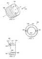
- FIG. 1is a schematic representation of an o-ring-less low profile fitting 3500 according to one embodiment of the invention.
- One end of fitting 3500has a fitting seal surface that is shaped, formed or otherwise structured to mate with a receiving seal surface, which can be part of a receiving hole machined out of a block (e.g., dispense block 205 of FIGS. 7-15 ).
- the other end of fitting 3500can be shaped, formed or otherwise structured to receive or fit into a tubular connection (e.g., a tube), which can be of any desirable size and configuration, depending upon applications (e.g., to connect a filter).
- fitting 3500has a first end 3501 and a second end 3502 .
- a top view of fitting 3500 in a direction as indicated by arrow 3503is shown in FIG. 2 .
- a cross-sectional view of fitting 3500 as indicated by line A-A′is shown in FIG. 3 .
- first end 3501has a seal surface 3505 that is defined by a first diameter 3506 and a second diameter 3507 .
- First diameter 3506is the inner diameter (I.D.) of rim 3511 , which is located at the very end of first end 3501 of fitting 3500 .
- Second diameter 3507is the inner diameter of fitting 3500 (i.e., the thru hole of fitting 3500 ).
- Seal surface 3505slops (e.g., 86 degrees) from first diameter 3506 to second diameter 3507 , which, according to one embodiment, begins shortly before protuberance 3512 .
- protuberance 3512can be seen as part of a support structure that supports seal surface 3505 and characterizes first end 3501 .
- Second end 3502is characterized by protuberance 3514 and contour 3513 around its opening.
- Second end 3502can be of any suitable application-specific shapes and sizes. More specifically, second end 3502 can be shaped, formed, or otherwise structured to fit various types of tubes and tube-like connectors, depending upon applications.
- protuberance 3512 and protuberance 3514have different diameters. Specifically, diameter 3508 of protuberance 3512 is larger than diameter 3509 of protuberance 3514 . The difference between diameter 3508 and diameter 3509 allows a locking nut to slide over protuberance 3514 and be stopped by protuberance 3512 .
- a locking nut for fitting 3500will be described below in more details with reference to FIGS. 4-9 .
- fitting 3500is made out of a block, rod, or other shaped piece of material.
- fitting 3500is made of a material that has a higher compressibility (i.e., softer) than that of the material of the receiving seal surface at the receiving end (e.g., a female-threaded receiving hole machined out of dispense block 205 of FIGS. 7-15 ).
- fitting 3500is made of Teflon® PFA and dispense block 205 is made of PTFE or modified PTFE As one skilled in the art can appreciate, the latter is a harder material (i.e., has lower compressibility) than the former.
- FIG. 4is a schematic representation of a locking nut 3600 for locking fitting 3500 onto a receiving end (e.g., receiving hole 3770 on dispense block 205 of FIG. 7 ).
- locking nut 3600has a first end 3601 and a second end 3602 .
- a top view of locking nut 3600 in a direction as indicated by arrow 3603is shown in FIG. 5 .
- a cross-sectional view of locking nut 3600 as indicated by line B-B′is shown in FIG. 6 .
- first end 3601may have a flat surface with holes 3604 to facilitate the use of a tool (e.g., securely locking fitting 3500 onto dispense block 205 using a torque wrench or other appropriate tools capable of providing about 8-10 in./lb torque).
- a toole.g., securely locking fitting 3500 onto dispense block 205 using a torque wrench or other appropriate tools capable of providing about 8-10 in./lb torque.
- locking nut 3600has a very low profile, which means that once locking nut 3600 secures fitting 3500 onto dispense block 205 , only a small portion of first end 3601 of locking nut 3600 would protrude from dispense block 205 .
- the low profile design of locking nut 3600reduces the protrusion after installation to be less than about 0.2 inch in height. This low profile design is one characteristic of locking nut 3600 .
- locking nut 3600is male-threaded. As shown in FIG. 6 , lock nut 3600 has male threads 3777 . It should be understood that male threads 3777 as shown in FIG. 6 are meant to be exemplary. The number as well as size of male threads 3777 can be implemented to suit, so long as the female threads of the receiver (e.g., receiving hole 3770 of block 205 of FIG. 7 ) at the receiving end match male threads 3777 .
- first end 3601 and second end 3602can, but not required to, have about the same outer diameters.
- first end 3601 and second end 3602have same outer diameter 3608 and different inner diameters 3606 and 3607 .
- Inner diameter 3606 at first end 3601is smaller than inner diameter 3607 at second end 3602 .
- second end 3602has a recess area 3609 , which is another characteristic of locking nut 3600 .
- Recess area 3609is useful in compressing down first end 3501 of fitting 3500 to ensure a secure fit and tight seal between fitting 3500 and dispense block 205 , which will be described in more details below with reference to FIGS. 7-9 .
- FIG. 7is a perspective view of a fitting assembly to be assembled on a manifold (e.g., dispense block 205 ), according to one embodiment of the invention.
- a manifoldi.e., a chamber or pipe with one or more openings for receiving and/or distributing a fluid or gas
- FIGS. 7-15a portion of dispense block 205 is shown in FIGS. 7-15 .
- the drawingsare not meant to be limiting as receivers for fitting assembly 3700 can be suitably implemented depending upon applications.
- dispense block 205can be part of pump 100 , which will be described in more details below with reference to FIGS. 10 and 15 .
- Other implementations of suitable manifolds with appropriate receivers for fitting assembly 3700are also possible and are not limited to dispense block 205 as shown in FIGS. 7-15 .
- fitting assembly 3700comprises fitting 3500 and locking nut 3600 .
- fitting 3500is positioned between locking nut 3600 and dispense block 205 .
- Second end 3602 of locking nut 3600is positioned to face dispense block 205
- first end 3501 of fitting 3500is positioned towards dispense block 205 so that seal surface 3505 faces dispense block 205 .
- inner diameter 3606 of locking nut 3600is larger than outer diameter 3509 of protuberance 3514 and smaller than outer diameter 3508 of protuberance 3512 .
- locking nut 3600can slide over protuberance 3514 of fitting 3500 and recess area 3609 of locking nut 3600 , which is defined by inner diameter 3607 , can serve as a stopper. That is, as male threads 3777 of locking nut 3600 are met with female threads 3778 of receiving hole 3770 , which are machined to receive accordingly, and screw fitting 3500 in place, recess area 3609 catches protuberance 3512 of fitting 3500 and presses it down.
- FIG. 8is a perspective view of fitting assembly 3700 as assembled on dispense block 205 , according to one embodiment of the invention.
- holes 3604 on locking nut 3600can facilitate locking fitting 3500 onto dispense block 205 .
- locking fitting 3500completes a seal between fitting 3500 and dispense block 205 , thereby creating a tight or perfect closure that prevents the entrance or escape of a fluid or gas. Details on how such a seal is created will be described below with reference to FIG. 9 .
- fitting assembly 3700is ready for use via second end 3502 of fitting 3500 .
- FIG. 9is a cross-sectional view of fitting assembly 3700 of FIGS. 7-8 .
- receiving hole 3770is machined out of dispense block 205 .
- the interior (e.g., dimension and configuration) of receiving hole 3770substantially matches part of the exterior of first end 3501 of fitting 3500 in conjunction with the exterior of locking nut 3600 . More specifically, as shown in FIG. 9 , the interior of receiving hole 3770 has female threads 3778 that matches male threads 3777 of locking nut 3600 and a recess area 3772 that matches seal surface 3505 and the contour of first end 3501 of fitting 3500 .
- first end 3501 of fitting 3500touches part of receiving hole 3770 at points 3771 (i.e., where seal surface 3505 interfaces with inner diameter 3507 , see FIG. 9 ) and there may be one or more slight gaps 3773 between surfaces of first end 3501 and receiving hole 3770 .
- Gaps 3773are shown exaggerated in FIG. 9 for the purpose of illustration. The actual amount of gaps may vary from implementation to implementation.
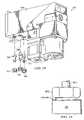
- FIG. 10is a diagrammatic representation of a partial assembly of pump 100 utilizing embodiments of the invention. More specifically, FIG. 10 illustrates adding filter fittings 335 , 340 , and 345 to dispense block 205 .
- nuts 350 , 355 , 360are used to hold filter fittings 335 , 340 , 345 .
- a low profile filter fittinge.g., filter fitting 335
- a corresponding low profile nute.g., nut 350
- Low profile filter connectionsallow a filter (e.g., filter 120 ) to be closely attached to dispense block 205 , which helps to reduce the overall dimension of pump 100 .
- filter fittings 335 , 340 , 345implement embodiments of fitting 3500 and nuts 350 , 355 , 360 implement embodiments of locking nut 3600 as described above with reference to FIGS. 1-9 .
- Each filter fittingleads to one of the flow passages of dispense block 205 (e.g., a feed chamber, vent outlet, dispense chamber, etc.).
- Pump 100can be a multi-stage or single stage pump. Examples of pump 100 can be found in U.S. patent application Ser. No. 11/602,464, filed Nov. 20, 2006, entitled “SYSTEM AND METHOD FOR MULTIPLE-STAGE PUMP WITH REDUCED FORM FACTOR” by Gonnella et al., the content of which is incorporated herein by reference.
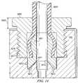
- FIG. 11is a perspective view of a tube to be connected to a manifold through an o-ring-less low profile fitting assembly, according to another embodiment of the invention. More specifically, FIG. 11 illustrates one embodiment of a fluid fitting assembly 3800 having a locking nut 3802 and a fitting 3801 . In this example, fitting 3801 is pressed into one end of tube 3803 .
- Locking nut 3802like locking nut 3600 described above, is male threaded on the outside and hollow on the inside (i.e., has a through hole). As one in the art can appreciate, locking nut 3802 is not limited to what is shown in FIG.
- locking nut 3802can be modified with features such as holes 3604 of locking nut 3600 to facilitate the use of a tool.
- locking nut 3802need not have a hexagon-shaped head.
- fitting 3801can be a commercially available sleeve that can serve as a cap end for tube 3803 and fit inside the screw end of locking nut 3802 (see cross-sectional view shown in FIG. 14 ).
- the inner diameter of locking nut 3802is sufficiently large to fit the outer diameter of tube 3803 .
- tube 3803 and locking nut 3802are not physically attached (i.e., one can spin locking nut 3802 around tube 3803 ).
- Decoupling tube 3803 and locking nut 3802advantageously eliminates unscrewing issues related to movements of tube 3803 .
- FIG. 12is a perspective view of a receiving hole machined according to another embodiment of the invention. More specifically, receiving hole 3970 is machined out of dispense block 205 for receiving tube 3803 and fitting assembly 3800 . As will be described in detail with reference to FIG. 15 , one embodiment of receiving hole 3970 is an external inlet connecting a flow path of dispense block 205 with a fluid line of pump 100 .
- fluid fitting assemblies disclosed hereincan be utilized to connect external inlets as well as outlets of various dispense blocks to fluid lines and thus are not limited by what is shown here. As illustrated in FIG.
- FIG. 13is a side view showing fitting assembly 3800 being assembled onto dispense block 205 , according to one embodiment of the invention. More specifically, FIG. 13 shows locking nut 3802 partially screwed into receiving hole 3970 (not shown) of dispense block 205 . Because locking nut 3802 and tube 3803 are not physically attached, movements (e.g., bending) of tube 3803 does not affect locking nut 3802 (e.g., bending tube 3803 will not cause locking nut 3802 to loosen up or become unscrewed).
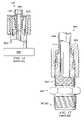
- FIG. 14is a cross-sectional view of FIG. 13 , according to another embodiment of the invention.
- FIG. 14exemplifies the low profile characteristic of fluid fitting assembly 3800 .
- the only part of fluid fitting assembly 3800 that sticks out dispense block 205is limited by height 3980 .
- height 3980is about a quarter of an inch (0.25′′).
- the head of locking nut 3802can be trimmed down to reduce height 3980 , the portion of fitting assembly 3800 protruding from dispense block 205 . In one embodiment, this is achieved by machining locking nut 3802 with less height and adding holes similar to holes 3604 of locking nut 3600 on to top face of locking nut 3802 .
- Locking nut 3802can look like locking nut 3602 , without the wrench flats.
- part of fitting 3801touches or contacts part of receiving hole 3970 at points 3971 (i.e., similar to where seal surface 3505 interfaces with inner diameter 3507 of fitting 3500 as described above with reference to FIG. 9 ).
- Gaps 3973 as shown in FIG. 14are meant to be exemplary. Actual size of gaps 3973 may vary from implementation to implementation.
- having fitting 3801 to contact dispense block 205 at points 3971advantageously eliminates dead spaces, in addition to completing the seal between fitting 3801 and dispense block 205 .
- tube 3803is not limited to what is shown in FIGS. 11-14 .
- tube 3803can be a tube-like adaptor having one end connecting fitting 3801 with a tube or another tube-like apparatus. The other end can vary from implementation to implementation.
- Such a tube-like adaptor 3803can be modified to suit, connecting a variety of devices with dispense block 205 through fitting 3801 and locking nut 3802 , which can be particularly useful in retro-fitting existing air and/or fluid fittings.
- fitting 3801begins to deform and fill gaps 3973 (starting from points 3971 towards recess area 3972 ), completing the seal between fitting 3801 and dispense block 205 .
- FIG. 15is a diagrammatic representation of one embodiment of a pump assembly for pump 100 .
- Pump 100can include a dispense block 205 that defines various fluid flow paths through pump 100 and at least partially defines feed chamber 155 and dispense chamber 185 .
- Dispense pump block 205can be a unitary block of PTFE, modified PTFE or other material. Because these materials do not react with or is minimally reactive with many process fluids, the use of these materials allows flow passages and pump chambers to be machined directly into dispense block 205 with a minimum of additional hardware. Dispense block 205 consequently reduces the need for piping by providing an integrated fluid manifold.
- Dispense block 205can include various external inlets and outlets including, for example, inlet 210 through which the fluid is received, vent outlet 215 for venting fluid during the vent segment, and dispense outlet 220 through which fluid is dispensed during the dispense segment.
- Embodiments of the invention disclosed hereincan be utilized to connect the external inlets and outlets, including external purge outlets, of dispense block 205 to fluid lines. More specifically, one embodiment of fitting assembly 3800 can be implemented as an input fluid fitting assembly for inlet 210 , one embodiment of fitting assembly 3800 can be implemented as a vent fitting assembly for vent outlet 215 , and one embodiment of fitting assembly 3800 can be implemented as an output fitting assembly for dispense output 220 . Other implementations for fluid connections are also possible.
- Dispense block 205routes fluid to a feed pump (not shown), a dispense pump (not shown), and filter 120 .
- Pump cover or housing 225can protect the feed motor and the dispense motor from damage, while piston housing 227 can provide protection for the pistons (not shown).
- Either housingcan be formed of polyethylene or other polymer.
- Valve plate 230provides a valve housing for a system of valves (not shown) that can be configured to direct fluid flow to various components of multi-stage pump 100 .
- Valve plate 230includes several valve control inlets (e.g., 235 , 240 , 245 , 250 , 255 ), each corresponds to a valve for applying pressure or vacuum to its corresponding diaphragm.
- inlets 235 , 240 , 245 , 250 , 255By the selective application of pressure or vacuum to inlets 235 , 240 , 245 , 250 , 255 , the corresponding valves are opened and closed. Additional teachings related to inlets 235 , 240 , 245 , 250 , and 255 can be found in the above-referenced U.S. Patent Application Ser. No. 60/742,435, filed Dec. 5, 2005, entitled “SYSTEM AND METHOD FOR MULTIPLE-STAGE PUMP WITH REDUCED FORM FACTOR” by Gonnella et al.
- valve control gas and vacuumare provided to valve plate 230 via valve control supply lines 260 , which run from a valve control manifold (covered by top cover 263 ), through dispense block 205 to valve plate 230 .
- Valve control gas supply inlet 265provides a pressurized gas to the valve control manifold and vacuum inlet 270 provides vacuum (or low pressure) to the valve control manifold.
- the valve control manifoldacts as a three way valve to route pressurized gas or vacuum to the appropriate inlets of valve plate 230 via supply lines 260 to actuate the corresponding valve(s).
- FIG. 15also illustrates several features that can prevent fluid drips from entering the area of multi-stage pump 100 housing electronics. Fluid drips can occur, for example, when an operator connects or disconnects a tube from inlet 210 , outlet 215 or vent 220 .
- the “drip-proof” featuresare designed to prevent drips of potentially harmful chemicals from entering the pump, particularly the electronics chamber and do not necessarily require that the pump be “water-proof”(e.g., submersible in fluid without leakage). According to other embodiments, the pump can be fully sealed.
- dispense block 205can include a vertically protruding flange or lip 272 protruding outward from the edge of dispense block 205 that meets top cover 263 .
- the top of top cover 263is flush with the top surface of lip 272 . This causes drips near the top interface of dispense block 205 and top cover 263 to tend to run onto dispense block 205 , rather than through the interface.
- top cover 263is flush with the base of lip 272 or otherwise inwardly offset from the outer surface of lip 272 .
- top cover 263 and lip 272This causes drips to tend to flow down the corner created by top cover 263 and lip 272 , rather than between top cover 263 and dispense block 205 . Additionally, a rubber seal is placed between the top edge of top cover 263 and back plate 271 to prevent drips from leaking between top cover 263 and back plate 271 .
- Dispense block 205can also include sloped feature 273 that includes a sloped surface defined in dispense block 205 that slopes down and away from the area of pump 100 housing electronics. Consequently, drips near the top of dispense block 205 are lead away from the electronics. Additionally, pump cover 225 can also be offset slightly inwards from the outer side edges of dispense block 205 so that drips down the side of pump 100 will tend to flow past the interface of pump cover 225 and other portions of pump 100 .
- multi-stage pump 100can include seals, sloped features and other features to prevent drips from entering portions of multi-stage pump 100 housing electronics.
- Back plate 271can include features to further “drip-proof” multi-stage pump 100 .
- Embodiments of multi-stage pump 100 as shown in FIGS. 10 and 15have a compact design. To this extent, embodiments of the o-ring-less low profile fittings and fitting assemblies disclosed herein can be highly desirable and valuable. More specifically, fitting assembly 3700 can be particularly useful for filter connections, as shown in FIG. 10 , and fitting assembly 3800 can be particularly useful for fluid connections, as shown in FIG. 15 .
- FIG. 16is a diagrammatic representation of a prior art fitting assembly which fits over a stem protruding from a manifold. More specifically, fitting assembly 3990 comprises fitting 3991 and nut 3992 . Fitting 3991 is inserted into stem 3993 which sticks out of manifold 3994 and which is male-threaded on the outside. Tube 3995 is pressed down onto fitting 3991 and over stem 3993 by nut 3992 , which is female-threaded on the inside.
- fitting assembly 3990has a large profile, which is not a desirable feature in fluid pumps.
- fitting assembly 3990likely cause issues when tube 3995 is bent.
- FIG. 17is a diagrammatic representation of another prior art fitting assembly which uses an adapter. More specifically, fitting assembly 3996 comprises adapter 3997 and nut 3998 for connecting flared tubing 3999 to a manifold (not shown). Nut 3998 is female-threaded on the inside to screw on adapter 3997 , which is male-threaded on the outside. When installed, other than the threaded portion below its body, the rest of fitting assembly 3996 sticks out of the manifold much like stem 3993 sticks out of manifold 3994 as shown in FIG. 16 . With this prior design, drawbacks such as leakage and dead spaces remain. Furthermore, the bulkiness and large profile likely to cause issues when flared tubing 3999 is bent.
- Embodiments of the fitting assemblies disclosed hereinhave many space-saving features and characteristics, advantageously achieving a desirable low profile with minimal protrusion from a manifold while ensuring a secure seal between each fitting and the manifold.
- an o-ring-less low profile connection/fitting assemblyallows a filter (e.g., filter 120 of FIG. 15 ), tube (e.g., tube 3803 of FIG. 14 ), or tube-like adaptor to be closely attached to a manifold (e.g., dispense block 205 ), which helps to desirably reduce the overall dimension of the pump that embodies the manifold, which, in turn, helps to reduce the overall dimension of a pumping system that embodies the pump(s).
- the low profile designalso helps to reduce effects associated with tube movements.
- an o-ring-less low profile fitting assemblycan be disassembled and then reassembled (i.e., reused) several times without losing the seal or causing a leakage problem.
- filter fitting assembly 3700can be disassembled by unscrewing locking nut 3600 and then reassembled by tightening locking nut 3600 again. Because of the elasticity of fitting 3500 , the tightening of locking nut 3600 can complete the seal between fitting 3500 and dispense block 250 in a similar manner as it was first assembled.
- fluid fitting assembly 3800can be disassembled by unscrewing locking nut 3802 and then reassembled by tightening locking nut 3802 again to complete the seal between fitting 3801 and dispense block 205 .
- fitting assembly 3700is shown to protrude from dispense block 205 by height 3780 .
- height 3780is about 0.20 inch or less.
- Fitting assembly 3800can be similarly modified.
- one important advantage of the inventionis that no o-rings are required.
- the elimination of the o-ringeliminates all the drawbacks associated with o-rings (e.g., prone to leaks, limited lifespan, etc.) in prior fittings and fitting assemblies.
- gaps 3773may be filled before a seal is complete, leaving a possible dead zone in the flow path around points 3771 .
- dead zones and gapsare advantageously eliminated in the embodiment shown in FIG. 14 .
- Yet another advantageis the reduced cost in machining receiving hole(s) 3770 and/or receiving hole(s) 3970 out of dispense block 205 .
- Prior pumping systemsuse pillar style fittings and female threaded nut, which requires pillar style structures (e.g., stems) with male threads to match. In addition to their bulky size and large profile, these stems are difficult and wasteful to machine out of a dispense block.
- the low profile design of filter fitting assembly 3700 and fluid fitting assembly 3800minimizes the amount of material and steps necessary to machine corresponding receiving hole(s), effectively saving material, space, time, and money.
Landscapes
- Engineering & Computer Science (AREA)
- General Engineering & Computer Science (AREA)
- Mechanical Engineering (AREA)
- Gasket Seals (AREA)
- Mutual Connection Of Rods And Tubes (AREA)
- General Details Of Gearings (AREA)
- Compressor (AREA)
- Details Of Reciprocating Pumps (AREA)
Abstract
Description
Claims (18)
Priority Applications (1)
| Application Number | Priority Date | Filing Date | Title |
|---|---|---|---|
| US11/602,513US7547049B2 (en) | 2005-12-02 | 2006-11-20 | O-ring-less low profile fittings and fitting assemblies |
Applications Claiming Priority (2)
| Application Number | Priority Date | Filing Date | Title |
|---|---|---|---|
| US74166705P | 2005-12-02 | 2005-12-02 | |
| US11/602,513US7547049B2 (en) | 2005-12-02 | 2006-11-20 | O-ring-less low profile fittings and fitting assemblies |
Publications (2)
| Publication Number | Publication Date |
|---|---|
| US20070126233A1 US20070126233A1 (en) | 2007-06-07 |
| US7547049B2true US7547049B2 (en) | 2009-06-16 |
Family
ID=38123368
Family Applications (1)
| Application Number | Title | Priority Date | Filing Date |
|---|---|---|---|
| US11/602,513Active2027-03-04US7547049B2 (en) | 2005-12-02 | 2006-11-20 | O-ring-less low profile fittings and fitting assemblies |
Country Status (5)
| Country | Link |
|---|---|
| US (1) | US7547049B2 (en) |
| JP (2) | JP5302002B2 (en) |
| KR (1) | KR20080073778A (en) |
| TW (1) | TW200726918A (en) |
| WO (1) | WO2007067343A2 (en) |
Cited By (21)
| Publication number | Priority date | Publication date | Assignee | Title |
|---|---|---|---|---|
| US20070104586A1 (en)* | 1998-11-23 | 2007-05-10 | James Cedrone | System and method for correcting for pressure variations using a motor |
| US20070128046A1 (en)* | 2005-12-02 | 2007-06-07 | George Gonnella | System and method for control of fluid pressure |
| US20070127511A1 (en)* | 2005-12-02 | 2007-06-07 | James Cedrone | I/O systems, methods and devices for interfacing a pump controller |
| US20070125796A1 (en)* | 2005-12-05 | 2007-06-07 | James Cedrone | Error volume system and method for a pump |
| US20070128047A1 (en)* | 2005-12-02 | 2007-06-07 | George Gonnella | System and method for monitoring operation of a pump |
| US20070128048A1 (en)* | 2005-12-02 | 2007-06-07 | George Gonnella | System and method for position control of a mechanical piston in a pump |
| US20070125797A1 (en)* | 2005-12-02 | 2007-06-07 | James Cedrone | System and method for pressure compensation in a pump |
| US20070128050A1 (en)* | 2005-11-21 | 2007-06-07 | James Cedrone | System and method for a pump with reduced form factor |
| US20070217442A1 (en)* | 2006-03-01 | 2007-09-20 | Mcloughlin Robert F | System and method for multiplexing setpoints |
| US20090116334A1 (en)* | 2006-03-01 | 2009-05-07 | Entegris, Inc. | Method for controlled mixing of fluids via temperature |
| US20100262304A1 (en)* | 2005-12-02 | 2010-10-14 | George Gonnella | System and method for valve sequencing in a pump |
| WO2011106254A1 (en) | 2010-02-26 | 2011-09-01 | Entegris, Inc | Method and system for optimizing operation of a pump |
| WO2011106253A1 (en) | 2010-02-26 | 2011-09-01 | Entegris, Inc | Apparatus and method for controlling operation of a pump based on filter information in a filter information tag |
| WO2012054706A2 (en) | 2010-10-20 | 2012-04-26 | Entegris, Inc | Method and system for pump priming |
| US8292598B2 (en) | 2004-11-23 | 2012-10-23 | Entegris, Inc. | System and method for a variable home position dispense system |
| WO2013052082A1 (en) | 2011-10-03 | 2013-04-11 | Entegris, Inc | Modular filter cassette |
| WO2014055451A2 (en) | 2012-10-01 | 2014-04-10 | Entegris, Inc. | Purifier cassette |
| US20140147230A1 (en)* | 2011-08-31 | 2014-05-29 | Aoyama Seisakusho Co., Ltd. | Anti-seizing nut |
| US8753097B2 (en) | 2005-11-21 | 2014-06-17 | Entegris, Inc. | Method and system for high viscosity pump |
| US20160177783A1 (en)* | 2013-12-10 | 2016-06-23 | United Technologies Corporation | Housing support nut connection |
| US9631611B2 (en) | 2006-11-30 | 2017-04-25 | Entegris, Inc. | System and method for operation of a pump |
Families Citing this family (5)
| Publication number | Priority date | Publication date | Assignee | Title |
|---|---|---|---|---|
| KR101029363B1 (en)* | 2008-12-04 | 2011-04-13 | 주식회사 에이에스티젯텍 | Air tank manufacturing method using aluminum profile |
| GB201015679D0 (en)* | 2010-09-20 | 2010-10-27 | Cummins Ltd | Variable geometry turbine |
| US10763189B2 (en)* | 2014-08-29 | 2020-09-01 | International Business Machines Corporation | Sealing arrangement |
| US10760569B2 (en)* | 2017-05-24 | 2020-09-01 | John L. Strelow | Reciprocating pumps and closures therefore |
| SG11202103185XA (en)* | 2018-10-15 | 2021-04-29 | Electro Scientific Industries Inc | Systems and methods for use in handling components |
Citations (122)
| Publication number | Priority date | Publication date | Assignee | Title |
|---|---|---|---|---|
| US269626A (en)* | 1882-12-26 | brauee | ||
| US826018A (en)* | 1904-11-21 | 1906-07-17 | Isaac Robert Concoff | Hose-coupling. |
| US1664125A (en)* | 1926-11-10 | 1928-03-27 | John R Lowrey | Hose coupling |
| US2153664A (en)* | 1937-03-08 | 1939-04-11 | Dayton Rubber Mfg Co | Strainer |
| US2215505A (en) | 1938-06-13 | 1940-09-24 | Byron Jackson Co | Variable capacity pumping apparatus |
| US2328468A (en)* | 1940-12-07 | 1943-08-31 | Laffly Edmond Gabriel | Coupling device for the assembly of tubular elements |
| US2457384A (en)* | 1947-02-17 | 1948-12-28 | Ace Glass Inc | Clamp for spherical joints |
| GB661522A (en) | 1949-03-31 | 1951-11-21 | Eureka Williams Corp | Improvements in or relating to oil burners |
| US2631538A (en) | 1949-11-17 | 1953-03-17 | Wilford C Thompson | Diaphragm pump |
| US2673522A (en) | 1951-04-10 | 1954-03-30 | Bendix Aviat Corp | Diaphragm pump |
| US2757966A (en)* | 1952-11-06 | 1956-08-07 | Samiran David | Pipe coupling |
| US3072058A (en) | 1961-08-18 | 1963-01-08 | Socony Mobil Oil Co Inc | Pipe line control system |
| US3227279A (en) | 1963-05-06 | 1966-01-04 | Conair | Hydraulic power unit |
| US3327635A (en) | 1965-12-01 | 1967-06-27 | Texsteam Corp | Pumps |
| US3623661A (en) | 1969-02-28 | 1971-11-30 | Josef Wagner | Feed arrangement for spray painting |
| US3741298A (en) | 1971-05-17 | 1973-06-26 | L Canton | Multiple well pump assembly |
| US3895748A (en) | 1974-04-03 | 1975-07-22 | George R Klingenberg | No drip suck back units for glue or other liquids either separately installed with or incorporated into no drip suck back liquid applying and control apparatus |
| US3954352A (en) | 1972-11-13 | 1976-05-04 | Toyota Jidosha Kogyo Kabushiki Kaisha | Diaphragm vacuum pump |
| US4023592A (en) | 1976-03-17 | 1977-05-17 | Addressograph Multigraph Corporation | Pump and metering device |
| US4093403A (en) | 1976-09-15 | 1978-06-06 | Outboard Marine Corporation | Multistage fluid-actuated diaphragm pump with amplified suction capability |
| US4452265A (en) | 1979-12-27 | 1984-06-05 | Loennebring Arne | Method and apparatus for mixing liquids |
| US4483665A (en) | 1982-01-19 | 1984-11-20 | Tritec Industries, Inc. | Bellows-type pump and metering system |
| US4541455A (en) | 1983-12-12 | 1985-09-17 | Tritec Industries, Inc. | Automatic vent valve |
| US4597719A (en) | 1983-03-28 | 1986-07-01 | Canon Kabushiki Kaisha | Suck-back pump |
| US4597721A (en) | 1985-10-04 | 1986-07-01 | Valco Cincinnati, Inc. | Double acting diaphragm pump with improved disassembly means |
| US4601409A (en) | 1984-11-19 | 1986-07-22 | Tritec Industries, Inc. | Liquid chemical dispensing system |
| US4614438A (en) | 1984-04-24 | 1986-09-30 | Kabushiki Kaisha Kokusai Technicals | Method of mixing fuel oils |
| US4671545A (en)* | 1985-01-29 | 1987-06-09 | Toyoda Gosei Co., Ltd. | Female-type coupling nipple |
| US4690621A (en) | 1986-04-15 | 1987-09-01 | Advanced Control Engineering | Filter pump head assembly |
| US4705461A (en) | 1979-09-19 | 1987-11-10 | Seeger Corporation | Two-component metering pump |
| US4808077A (en) | 1987-01-09 | 1989-02-28 | Hitachi, Ltd. | Pulsationless duplex plunger pump and control method thereof |
| US4821997A (en) | 1986-09-24 | 1989-04-18 | The Board Of Trustees Of The Leland Stanford Junior University | Integrated, microminiature electric-to-fluidic valve and pressure/flow regulator |
| US4824073A (en) | 1986-09-24 | 1989-04-25 | Stanford University | Integrated, microminiature electric to fluidic valve |
| US4865525A (en) | 1986-09-19 | 1989-09-12 | Grunbeck Wasseraufbereitung Gmbh | Metering pump |
| US4915126A (en) | 1986-01-20 | 1990-04-10 | Dominator Maskin Ab | Method and arrangement for changing the pressure in pneumatic or hydraulic systems |
| US4943032A (en) | 1986-09-24 | 1990-07-24 | Stanford University | Integrated, microminiature electric to fluidic valve and pressure/flow regulator |
| US4950134A (en) | 1988-12-27 | 1990-08-21 | Cybor Corporation | Precision liquid dispenser |
| US4952386A (en) | 1988-05-20 | 1990-08-28 | Athens Corporation | Method and apparatus for purifying hydrogen fluoride |
| US4966646A (en) | 1986-09-24 | 1990-10-30 | Board Of Trustees Of Leland Stanford University | Method of making an integrated, microminiature electric-to-fluidic valve |
| US5061156A (en) | 1990-05-18 | 1991-10-29 | Tritec Industries, Inc. | Bellows-type dispensing pump |
| US5061574A (en) | 1989-11-28 | 1991-10-29 | Battelle Memorial Institute | Thick, low-stress films, and coated substrates formed therefrom |
| US5062770A (en) | 1989-08-11 | 1991-11-05 | Systems Chemistry, Inc. | Fluid pumping apparatus and system with leak detection and containment |
| US5134962A (en) | 1989-09-29 | 1992-08-04 | Hitachi, Ltd. | Spin coating apparatus |
| US5135031A (en) | 1989-09-25 | 1992-08-04 | Vickers, Incorporated | Power transmission |
| US5167837A (en) | 1989-03-28 | 1992-12-01 | Fas-Technologies, Inc. | Filtering and dispensing system with independently activated pumps in series |
| US5192198A (en) | 1989-08-31 | 1993-03-09 | J. Wagner Gmbh | Diaphragm pump construction |
| US5262068A (en) | 1991-05-17 | 1993-11-16 | Millipore Corporation | Integrated system for filtering and dispensing fluid having fill, dispense and bubble purge strokes |
| US5261442A (en) | 1992-11-04 | 1993-11-16 | Bunnell Plastics, Inc. | Diaphragm valve with leak detection |
| US5316181A (en) | 1990-01-29 | 1994-05-31 | Integrated Designs, Inc. | Liquid dispensing system |
| US5344195A (en)* | 1992-07-29 | 1994-09-06 | General Electric Company | Biased fluid coupling |
| US5350200A (en)* | 1994-01-10 | 1994-09-27 | General Electric Company | Tube coupling assembly |
| US5380019A (en) | 1992-07-01 | 1995-01-10 | Furon Company | Spring seal |
| US5434774A (en) | 1994-03-02 | 1995-07-18 | Fisher Controls International, Inc. | Interface apparatus for two-wire communication in process control loops |
| US5476004A (en) | 1994-05-27 | 1995-12-19 | Furon Company | Leak-sensing apparatus |
| US5490765A (en) | 1993-05-17 | 1996-02-13 | Cybor Corporation | Dual stage pump system with pre-stressed diaphragms and reservoir |
| US5511797A (en) | 1993-07-28 | 1996-04-30 | Furon Company | Tandem seal gasket assembly |
| US5527161A (en) | 1992-02-13 | 1996-06-18 | Cybor Corporation | Filtering and dispensing system |
| US5546009A (en) | 1994-10-12 | 1996-08-13 | Raphael; Ian P. | Detector system using extremely low power to sense the presence or absence of an inert or hazardous fuild |
| US5575311A (en) | 1995-01-13 | 1996-11-19 | Furon Company | Three-way poppet valve apparatus |
| US5580103A (en) | 1994-07-19 | 1996-12-03 | Furon Company | Coupling device |
| US5599100A (en) | 1994-10-07 | 1997-02-04 | Mobil Oil Corporation | Multi-phase fluids for a hydraulic system |
| US5599394A (en) | 1993-10-07 | 1997-02-04 | Dainippon Screen Mfg., Co., Ltd. | Apparatus for delivering a silica film forming solution |
| US5645301A (en) | 1995-11-13 | 1997-07-08 | Furon Company | Fluid transport coupling |
| US5652391A (en) | 1995-05-12 | 1997-07-29 | Furon Company | Double-diaphragm gauge protector |
| US5653251A (en) | 1995-03-06 | 1997-08-05 | Reseal International Limited Partnership | Vacuum actuated sheath valve |
| US5743293A (en) | 1994-06-24 | 1998-04-28 | Robertshaw Controls Company | Fuel control device and methods of making the same |
| US5785508A (en) | 1994-04-13 | 1998-07-28 | Knf Flodos Ag | Pump with reduced clamping pressure effect on flap valve |
| US5793754A (en) | 1996-03-29 | 1998-08-11 | Eurotherm Controls, Inc. | Two-way, two-wire analog/digital communication system |
| EP0863538A2 (en) | 1997-03-03 | 1998-09-09 | Tokyo Electron Limited | Coating apparatus and coating method |
| EP0867649A2 (en) | 1997-03-25 | 1998-09-30 | SMC Kabushiki Kaisha | Suck back valve |
| US5839828A (en) | 1996-05-20 | 1998-11-24 | Glanville; Robert W. | Static mixer |
| US5848605A (en) | 1997-11-12 | 1998-12-15 | Cybor Corporation | Check valve |
| EP0892204A2 (en) | 1997-07-14 | 1999-01-20 | Furon Company | Improved diaphragm valve with leak detection |
| JPH1126430A (en) | 1997-06-25 | 1999-01-29 | Samsung Electron Co Ltd | Wet etching apparatus for manufacturing semiconductor device and method of circulating etchant in wet etching apparatus |
| DE29909100U1 (en) | 1999-05-25 | 1999-08-12 | ARGE Meibes/Pleuger, 30916 Isernhagen | Pipe arrangement with filter |
| US5947702A (en) | 1996-12-20 | 1999-09-07 | Beco Manufacturing | High precision fluid pump with separating diaphragm and gaseous purging means on both sides of the diaphragm |
| US5971723A (en) | 1995-07-13 | 1999-10-26 | Knf Flodos Ag | Dosing pump |
| US5991279A (en) | 1995-12-07 | 1999-11-23 | Vistar Telecommunications Inc. | Wireless packet data distributed communications system |
| US6033302A (en) | 1997-11-07 | 2000-03-07 | Siemens Building Technologies, Inc. | Room pressure control apparatus having feedforward and feedback control and method |
| WO2000031416A1 (en) | 1998-11-23 | 2000-06-02 | Millipore Corporation | Pump controller for precision pumping apparatus |
| US6190565B1 (en) | 1993-05-17 | 2001-02-20 | David C. Bailey | Dual stage pump system with pre-stressed diaphragms and reservoir |
| US6238576B1 (en) | 1998-10-13 | 2001-05-29 | Koganei Corporation | Chemical liquid supply method and apparatus thereof |
| US6250502B1 (en) | 1999-09-20 | 2001-06-26 | Daniel A. Cote | Precision dispensing pump and method of dispensing |
| US6302660B1 (en) | 1999-10-28 | 2001-10-16 | Iwaki Co., Ltd | Tube pump with flexible tube diaphragm |
| US6318971B1 (en) | 1999-03-18 | 2001-11-20 | Kabushiki Kaisha Toyoda Jidoshokki Seisakusho | Variable displacement compressor |
| US6325932B1 (en) | 1999-11-30 | 2001-12-04 | Mykrolis Corporation | Apparatus and method for pumping high viscosity fluid |
| US6330517B1 (en) | 1999-09-17 | 2001-12-11 | Rosemount Inc. | Interface for managing process |
| US6348124B1 (en) | 1999-12-14 | 2002-02-19 | Applied Materials, Inc. | Delivery of polishing agents in a wafer processing system |
| US20020044536A1 (en) | 1997-01-14 | 2002-04-18 | Michihiro Izumi | Wireless communication system having network controller and wireless communication device connected to digital communication line, and method of controlling said system |
| US20020095240A1 (en) | 2000-11-17 | 2002-07-18 | Anselm Sickinger | Method and device for separating samples from a liquid |
| US6470950B2 (en) | 2000-05-09 | 2002-10-29 | Kenichi Shimizu | Rolled screen drawer |
| US6474950B1 (en) | 2000-07-13 | 2002-11-05 | Ingersoll-Rand Company | Oil free dry screw compressor including variable speed drive |
| US6478547B1 (en) | 1999-10-18 | 2002-11-12 | Integrated Designs L.P. | Method and apparatus for dispensing fluids |
| WO2002090771A2 (en) | 2001-05-09 | 2002-11-14 | The Provost Fellows And Scholars Of The College Of The Holy And Undivided Trinity Of Queen Elizabeth Near Dublin | A liquid pumping system |
| US6506030B1 (en) | 1999-01-05 | 2003-01-14 | Air Products And Chemicals, Inc. | Reciprocating pumps with linear motor driver |
| US6540265B2 (en)* | 2000-12-28 | 2003-04-01 | R. W. Beckett Corporation | Fluid fitting |
| US6554579B2 (en) | 2001-03-29 | 2003-04-29 | Integrated Designs, L.P. | Liquid dispensing system with enhanced filter |
| US6592825B2 (en) | 1996-05-31 | 2003-07-15 | Packard Instrument Company, Inc. | Microvolume liquid handling system |
| US20030148759A1 (en) | 2002-02-01 | 2003-08-07 | Sendo International Limited | Enabling and/or Inhibiting an Operation of a Wireless Communication Unit |
| US20030222798A1 (en) | 2002-06-03 | 2003-12-04 | Visteon Global Technologies, Inc. | Method for initializing position with an encoder |
| US20040072450A1 (en) | 2002-10-15 | 2004-04-15 | Collins Jimmy D. | Spin-coating methods and apparatuses for spin-coating, including pressure sensor |
| US6742992B2 (en) | 1988-05-17 | 2004-06-01 | I-Flow Corporation | Infusion device with disposable elements |
| US20040133728A1 (en) | 2000-12-08 | 2004-07-08 | The Boeing Company | Network device interface for digitally interfacing data channels to a controller a via network |
| US6767877B2 (en) | 2001-04-06 | 2004-07-27 | Akrion, Llc | Method and system for chemical injection in silicon wafer processing |
| US6837484B2 (en) | 2002-07-10 | 2005-01-04 | Saint-Gobain Performance Plastics, Inc. | Anti-pumping dispense valve |
| US20050061722A1 (en) | 2003-09-18 | 2005-03-24 | Kunihiko Takao | Pump, pump for liquid chromatography, and liquid chromatography apparatus |
| US6901791B1 (en) | 1999-10-19 | 2005-06-07 | Robert Bosch Gmbh | Method and device for diagnosing of a fuel supply system |
| US20050126985A1 (en) | 1996-07-12 | 2005-06-16 | Mykrolis Corporation | Connector apparatus and system including connector apparatus |
| US6925072B1 (en) | 2000-08-03 | 2005-08-02 | Ericsson Inc. | System and method for transmitting control information between a control unit and at least one sub-unit |
| US20050184087A1 (en) | 1998-11-23 | 2005-08-25 | Zagars Raymond A. | Pump controller for precision pumping apparatus |
| US6952618B2 (en) | 2000-10-05 | 2005-10-04 | Karl A Daulin | Input/output control systems and methods having a plurality of master and slave controllers |
| US20050232296A1 (en) | 2004-03-24 | 2005-10-20 | Stephan Schultze | Method for data transmission |
| US20050238497A1 (en) | 1999-12-17 | 2005-10-27 | Holst Peter A | Methods for compensating for pressure differences across valves in IV pumps |
| US20060015294A1 (en) | 2004-07-07 | 2006-01-19 | Yetter Forrest G Jr | Data collection and analysis system |
| US7013223B1 (en) | 2002-09-25 | 2006-03-14 | The Board Of Trustees Of The University Of Illinois | Method and apparatus for analyzing performance of a hydraulic pump |
| US20060083259A1 (en) | 2004-10-18 | 2006-04-20 | Metcalf Thomas D | Packet-based systems and methods for distributing data |
| WO2006057957A2 (en) | 2004-11-23 | 2006-06-01 | Entegris, Inc. | System and method for a variable home position dispense system |
| US7063785B2 (en) | 2003-08-01 | 2006-06-20 | Hitachi High-Technologies Corporation | Pump for liquid chromatography |
| US7083202B2 (en)* | 2002-07-20 | 2006-08-01 | Dr. Ing. H.C.F. Porsche Aktiengeselleschaft | Device for providing wall ducts for, and process of assembling, conduits, tubing or electric cables for motor vehicles |
| US7247245B1 (en) | 1999-12-02 | 2007-07-24 | Entegris, Inc. | Filtration cartridge and process for filtering a slurry |
| US7272452B2 (en) | 2004-03-31 | 2007-09-18 | Siemens Vdo Automotive Corporation | Controller with configurable connections between data processing components |
| US20080089361A1 (en) | 2005-10-06 | 2008-04-17 | Metcalf Thomas D | System and method for transferring data |
Family Cites Families (5)
| Publication number | Priority date | Publication date | Assignee | Title |
|---|---|---|---|---|
| JPS5181413U (en)* | 1974-12-23 | 1976-06-29 | ||
| JPS5481119U (en)* | 1977-11-19 | 1979-06-08 | ||
| JPS598065Y2 (en)* | 1978-05-15 | 1984-03-12 | 株式会社スギノマシン | Ultra high pressure fluid fitting |
| JPH1049072A (en)* | 1996-08-06 | 1998-02-20 | Hitachi Ltd | Gas discharge type display device and manufacturing method thereof |
| EP1593087A4 (en)* | 2003-01-30 | 2006-10-04 | Chase Medical Lp | A method and system for image processing and contour assessment |
- 2006
- 2006-11-20USUS11/602,513patent/US7547049B2/enactiveActive
- 2006-11-20WOPCT/US2006/044981patent/WO2007067343A2/enactiveSearch and Examination
- 2006-11-20KRKR1020087016064Apatent/KR20080073778A/ennot_activeWithdrawn
- 2006-11-20JPJP2008543343Apatent/JP5302002B2/enactiveActive
- 2006-11-21TWTW095142922Apatent/TW200726918A/enunknown
- 2013
- 2013-02-25JPJP2013034523Apatent/JP2013130295A/ennot_activeWithdrawn
Patent Citations (137)
| Publication number | Priority date | Publication date | Assignee | Title |
|---|---|---|---|---|
| US269626A (en)* | 1882-12-26 | brauee | ||
| US826018A (en)* | 1904-11-21 | 1906-07-17 | Isaac Robert Concoff | Hose-coupling. |
| US1664125A (en)* | 1926-11-10 | 1928-03-27 | John R Lowrey | Hose coupling |
| US2153664A (en)* | 1937-03-08 | 1939-04-11 | Dayton Rubber Mfg Co | Strainer |
| US2215505A (en) | 1938-06-13 | 1940-09-24 | Byron Jackson Co | Variable capacity pumping apparatus |
| US2328468A (en)* | 1940-12-07 | 1943-08-31 | Laffly Edmond Gabriel | Coupling device for the assembly of tubular elements |
| US2457384A (en)* | 1947-02-17 | 1948-12-28 | Ace Glass Inc | Clamp for spherical joints |
| GB661522A (en) | 1949-03-31 | 1951-11-21 | Eureka Williams Corp | Improvements in or relating to oil burners |
| US2631538A (en) | 1949-11-17 | 1953-03-17 | Wilford C Thompson | Diaphragm pump |
| US2673522A (en) | 1951-04-10 | 1954-03-30 | Bendix Aviat Corp | Diaphragm pump |
| US2757966A (en)* | 1952-11-06 | 1956-08-07 | Samiran David | Pipe coupling |
| US3072058A (en) | 1961-08-18 | 1963-01-08 | Socony Mobil Oil Co Inc | Pipe line control system |
| US3227279A (en) | 1963-05-06 | 1966-01-04 | Conair | Hydraulic power unit |
| US3327635A (en) | 1965-12-01 | 1967-06-27 | Texsteam Corp | Pumps |
| US3623661A (en) | 1969-02-28 | 1971-11-30 | Josef Wagner | Feed arrangement for spray painting |
| US3741298A (en) | 1971-05-17 | 1973-06-26 | L Canton | Multiple well pump assembly |
| US3954352A (en) | 1972-11-13 | 1976-05-04 | Toyota Jidosha Kogyo Kabushiki Kaisha | Diaphragm vacuum pump |
| US3895748A (en) | 1974-04-03 | 1975-07-22 | George R Klingenberg | No drip suck back units for glue or other liquids either separately installed with or incorporated into no drip suck back liquid applying and control apparatus |
| US4023592A (en) | 1976-03-17 | 1977-05-17 | Addressograph Multigraph Corporation | Pump and metering device |
| US4093403A (en) | 1976-09-15 | 1978-06-06 | Outboard Marine Corporation | Multistage fluid-actuated diaphragm pump with amplified suction capability |
| US4705461A (en) | 1979-09-19 | 1987-11-10 | Seeger Corporation | Two-component metering pump |
| US4452265A (en) | 1979-12-27 | 1984-06-05 | Loennebring Arne | Method and apparatus for mixing liquids |
| US4483665A (en) | 1982-01-19 | 1984-11-20 | Tritec Industries, Inc. | Bellows-type pump and metering system |
| US4597719A (en) | 1983-03-28 | 1986-07-01 | Canon Kabushiki Kaisha | Suck-back pump |
| US4541455A (en) | 1983-12-12 | 1985-09-17 | Tritec Industries, Inc. | Automatic vent valve |
| US4614438A (en) | 1984-04-24 | 1986-09-30 | Kabushiki Kaisha Kokusai Technicals | Method of mixing fuel oils |
| US4601409A (en) | 1984-11-19 | 1986-07-22 | Tritec Industries, Inc. | Liquid chemical dispensing system |
| US4671545A (en)* | 1985-01-29 | 1987-06-09 | Toyoda Gosei Co., Ltd. | Female-type coupling nipple |
| US4597721A (en) | 1985-10-04 | 1986-07-01 | Valco Cincinnati, Inc. | Double acting diaphragm pump with improved disassembly means |
| US4915126A (en) | 1986-01-20 | 1990-04-10 | Dominator Maskin Ab | Method and arrangement for changing the pressure in pneumatic or hydraulic systems |
| US4690621A (en) | 1986-04-15 | 1987-09-01 | Advanced Control Engineering | Filter pump head assembly |
| US4865525A (en) | 1986-09-19 | 1989-09-12 | Grunbeck Wasseraufbereitung Gmbh | Metering pump |
| US4966646A (en) | 1986-09-24 | 1990-10-30 | Board Of Trustees Of Leland Stanford University | Method of making an integrated, microminiature electric-to-fluidic valve |
| US4821997A (en) | 1986-09-24 | 1989-04-18 | The Board Of Trustees Of The Leland Stanford Junior University | Integrated, microminiature electric-to-fluidic valve and pressure/flow regulator |
| CA1271140A (en) | 1986-09-24 | 1990-07-03 | Mark Zdeblick | Integrated, microminiature electric-to-fluidic valve and pressure/flow regulator |
| US4943032A (en) | 1986-09-24 | 1990-07-24 | Stanford University | Integrated, microminiature electric to fluidic valve and pressure/flow regulator |
| EP0261972B1 (en) | 1986-09-24 | 1992-12-23 | The Board Of Trustees Of The Leland Stanford Junior University | Integrated, microminiature electric-to-fluidic valve and pressure/flow regulator and method of making same |
| US4824073A (en) | 1986-09-24 | 1989-04-25 | Stanford University | Integrated, microminiature electric to fluidic valve |
| US4808077A (en) | 1987-01-09 | 1989-02-28 | Hitachi, Ltd. | Pulsationless duplex plunger pump and control method thereof |
| US6742992B2 (en) | 1988-05-17 | 2004-06-01 | I-Flow Corporation | Infusion device with disposable elements |
| US4952386A (en) | 1988-05-20 | 1990-08-28 | Athens Corporation | Method and apparatus for purifying hydrogen fluoride |
| US4950134A (en) | 1988-12-27 | 1990-08-21 | Cybor Corporation | Precision liquid dispenser |
| US5772899A (en) | 1989-03-28 | 1998-06-30 | Millipore Investment Holdings Limited | Fluid dispensing system having independently operated pumps |
| US6105829A (en) | 1989-03-28 | 2000-08-22 | Millipore Investment Holdings, Ltd. | Fluid dispensing system |
| US5516429A (en) | 1989-03-28 | 1996-05-14 | Fastar, Ltd. | Fluid dispensing system |
| US6251293B1 (en) | 1989-03-28 | 2001-06-26 | Millipore Investment Holdings, Ltd. | Fluid dispensing system having independently operated pumps |
| US5167837A (en) | 1989-03-28 | 1992-12-01 | Fas-Technologies, Inc. | Filtering and dispensing system with independently activated pumps in series |
| US5062770A (en) | 1989-08-11 | 1991-11-05 | Systems Chemistry, Inc. | Fluid pumping apparatus and system with leak detection and containment |
| US5192198A (en) | 1989-08-31 | 1993-03-09 | J. Wagner Gmbh | Diaphragm pump construction |
| US5135031A (en) | 1989-09-25 | 1992-08-04 | Vickers, Incorporated | Power transmission |
| US5134962A (en) | 1989-09-29 | 1992-08-04 | Hitachi, Ltd. | Spin coating apparatus |
| US5061574A (en) | 1989-11-28 | 1991-10-29 | Battelle Memorial Institute | Thick, low-stress films, and coated substrates formed therefrom |
| US5316181A (en) | 1990-01-29 | 1994-05-31 | Integrated Designs, Inc. | Liquid dispensing system |
| US5061156A (en) | 1990-05-18 | 1991-10-29 | Tritec Industries, Inc. | Bellows-type dispensing pump |
| US5262068A (en) | 1991-05-17 | 1993-11-16 | Millipore Corporation | Integrated system for filtering and dispensing fluid having fill, dispense and bubble purge strokes |
| US5527161A (en) | 1992-02-13 | 1996-06-18 | Cybor Corporation | Filtering and dispensing system |
| US5380019A (en) | 1992-07-01 | 1995-01-10 | Furon Company | Spring seal |
| US5344195A (en)* | 1992-07-29 | 1994-09-06 | General Electric Company | Biased fluid coupling |
| US5261442A (en) | 1992-11-04 | 1993-11-16 | Bunnell Plastics, Inc. | Diaphragm valve with leak detection |
| US5490765A (en) | 1993-05-17 | 1996-02-13 | Cybor Corporation | Dual stage pump system with pre-stressed diaphragms and reservoir |
| US6190565B1 (en) | 1993-05-17 | 2001-02-20 | David C. Bailey | Dual stage pump system with pre-stressed diaphragms and reservoir |
| US5762795A (en) | 1993-05-17 | 1998-06-09 | Cybor Corporation | Dual stage pump and filter system with control valve between pump stages |
| US5511797A (en) | 1993-07-28 | 1996-04-30 | Furon Company | Tandem seal gasket assembly |
| US5599394A (en) | 1993-10-07 | 1997-02-04 | Dainippon Screen Mfg., Co., Ltd. | Apparatus for delivering a silica film forming solution |
| US5350200A (en)* | 1994-01-10 | 1994-09-27 | General Electric Company | Tube coupling assembly |
| US5434774A (en) | 1994-03-02 | 1995-07-18 | Fisher Controls International, Inc. | Interface apparatus for two-wire communication in process control loops |
| US5785508A (en) | 1994-04-13 | 1998-07-28 | Knf Flodos Ag | Pump with reduced clamping pressure effect on flap valve |
| US5476004A (en) | 1994-05-27 | 1995-12-19 | Furon Company | Leak-sensing apparatus |
| US5743293A (en) | 1994-06-24 | 1998-04-28 | Robertshaw Controls Company | Fuel control device and methods of making the same |
| US5580103A (en) | 1994-07-19 | 1996-12-03 | Furon Company | Coupling device |
| US5599100A (en) | 1994-10-07 | 1997-02-04 | Mobil Oil Corporation | Multi-phase fluids for a hydraulic system |
| US5546009A (en) | 1994-10-12 | 1996-08-13 | Raphael; Ian P. | Detector system using extremely low power to sense the presence or absence of an inert or hazardous fuild |
| US5575311A (en) | 1995-01-13 | 1996-11-19 | Furon Company | Three-way poppet valve apparatus |
| US5653251A (en) | 1995-03-06 | 1997-08-05 | Reseal International Limited Partnership | Vacuum actuated sheath valve |
| US5652391A (en) | 1995-05-12 | 1997-07-29 | Furon Company | Double-diaphragm gauge protector |
| US5971723A (en) | 1995-07-13 | 1999-10-26 | Knf Flodos Ag | Dosing pump |
| US5645301A (en) | 1995-11-13 | 1997-07-08 | Furon Company | Fluid transport coupling |
| US5991279A (en) | 1995-12-07 | 1999-11-23 | Vistar Telecommunications Inc. | Wireless packet data distributed communications system |
| US5793754A (en) | 1996-03-29 | 1998-08-11 | Eurotherm Controls, Inc. | Two-way, two-wire analog/digital communication system |
| US5839828A (en) | 1996-05-20 | 1998-11-24 | Glanville; Robert W. | Static mixer |
| US6592825B2 (en) | 1996-05-31 | 2003-07-15 | Packard Instrument Company, Inc. | Microvolume liquid handling system |
| US20050126985A1 (en) | 1996-07-12 | 2005-06-16 | Mykrolis Corporation | Connector apparatus and system including connector apparatus |
| US5947702A (en) | 1996-12-20 | 1999-09-07 | Beco Manufacturing | High precision fluid pump with separating diaphragm and gaseous purging means on both sides of the diaphragm |
| US20020044536A1 (en) | 1997-01-14 | 2002-04-18 | Michihiro Izumi | Wireless communication system having network controller and wireless communication device connected to digital communication line, and method of controlling said system |
| EP0863538A2 (en) | 1997-03-03 | 1998-09-09 | Tokyo Electron Limited | Coating apparatus and coating method |
| EP0867649A2 (en) | 1997-03-25 | 1998-09-30 | SMC Kabushiki Kaisha | Suck back valve |
| JPH1126430A (en) | 1997-06-25 | 1999-01-29 | Samsung Electron Co Ltd | Wet etching apparatus for manufacturing semiconductor device and method of circulating etchant in wet etching apparatus |
| EP0892204A2 (en) | 1997-07-14 | 1999-01-20 | Furon Company | Improved diaphragm valve with leak detection |
| US6033302A (en) | 1997-11-07 | 2000-03-07 | Siemens Building Technologies, Inc. | Room pressure control apparatus having feedforward and feedback control and method |
| US5848605A (en) | 1997-11-12 | 1998-12-15 | Cybor Corporation | Check valve |
| US6238576B1 (en) | 1998-10-13 | 2001-05-29 | Koganei Corporation | Chemical liquid supply method and apparatus thereof |
| US20050184087A1 (en) | 1998-11-23 | 2005-08-25 | Zagars Raymond A. | Pump controller for precision pumping apparatus |
| WO2000031416A1 (en) | 1998-11-23 | 2000-06-02 | Millipore Corporation | Pump controller for precision pumping apparatus |
| EP1133639B1 (en) | 1998-11-23 | 2004-06-09 | Mykrolis Corporation | Pump controller for precision pumping apparatus |
| US7029238B1 (en) | 1998-11-23 | 2006-04-18 | Mykrolis Corporation | Pump controller for precision pumping apparatus |
| US6506030B1 (en) | 1999-01-05 | 2003-01-14 | Air Products And Chemicals, Inc. | Reciprocating pumps with linear motor driver |
| US6318971B1 (en) | 1999-03-18 | 2001-11-20 | Kabushiki Kaisha Toyoda Jidoshokki Seisakusho | Variable displacement compressor |
| DE29909100U1 (en) | 1999-05-25 | 1999-08-12 | ARGE Meibes/Pleuger, 30916 Isernhagen | Pipe arrangement with filter |
| US6330517B1 (en) | 1999-09-17 | 2001-12-11 | Rosemount Inc. | Interface for managing process |
| US6250502B1 (en) | 1999-09-20 | 2001-06-26 | Daniel A. Cote | Precision dispensing pump and method of dispensing |
| US6742993B2 (en) | 1999-10-18 | 2004-06-01 | Integrated Designs, L.P. | Method and apparatus for dispensing fluids |
| US6478547B1 (en) | 1999-10-18 | 2002-11-12 | Integrated Designs L.P. | Method and apparatus for dispensing fluids |
| US6901791B1 (en) | 1999-10-19 | 2005-06-07 | Robert Bosch Gmbh | Method and device for diagnosing of a fuel supply system |
| US6302660B1 (en) | 1999-10-28 | 2001-10-16 | Iwaki Co., Ltd | Tube pump with flexible tube diaphragm |
| US6325932B1 (en) | 1999-11-30 | 2001-12-04 | Mykrolis Corporation | Apparatus and method for pumping high viscosity fluid |
| US7383967B2 (en) | 1999-11-30 | 2008-06-10 | Entegris, Inc. | Apparatus and methods for pumping high viscosity fluids |
| US6635183B2 (en) | 1999-11-30 | 2003-10-21 | Mykrolis Corporation | Apparatus and methods for pumping high viscosity fluids |
| US20060070960A1 (en) | 1999-11-30 | 2006-04-06 | Gibson Gregory M | Apparatus and methods for pumping high viscosity fluids |
| US20040050771A1 (en) | 1999-11-30 | 2004-03-18 | Gibson Gregory M. | Apparatus and methods for pumping high viscosity fluids |
| WO2001040646A3 (en) | 1999-11-30 | 2002-05-10 | Mykrolis Corp | Vertically oriented pump for high viscosity fluids |
| US7247245B1 (en) | 1999-12-02 | 2007-07-24 | Entegris, Inc. | Filtration cartridge and process for filtering a slurry |
| US6348124B1 (en) | 1999-12-14 | 2002-02-19 | Applied Materials, Inc. | Delivery of polishing agents in a wafer processing system |
| US20050238497A1 (en) | 1999-12-17 | 2005-10-27 | Holst Peter A | Methods for compensating for pressure differences across valves in IV pumps |
| US6470950B2 (en) | 2000-05-09 | 2002-10-29 | Kenichi Shimizu | Rolled screen drawer |
| US6474950B1 (en) | 2000-07-13 | 2002-11-05 | Ingersoll-Rand Company | Oil free dry screw compressor including variable speed drive |
| US6925072B1 (en) | 2000-08-03 | 2005-08-02 | Ericsson Inc. | System and method for transmitting control information between a control unit and at least one sub-unit |
| US6952618B2 (en) | 2000-10-05 | 2005-10-04 | Karl A Daulin | Input/output control systems and methods having a plurality of master and slave controllers |
| US20020095240A1 (en) | 2000-11-17 | 2002-07-18 | Anselm Sickinger | Method and device for separating samples from a liquid |
| US20040133728A1 (en) | 2000-12-08 | 2004-07-08 | The Boeing Company | Network device interface for digitally interfacing data channels to a controller a via network |
| US6540265B2 (en)* | 2000-12-28 | 2003-04-01 | R. W. Beckett Corporation | Fluid fitting |
| US6554579B2 (en) | 2001-03-29 | 2003-04-29 | Integrated Designs, L.P. | Liquid dispensing system with enhanced filter |
| US6767877B2 (en) | 2001-04-06 | 2004-07-27 | Akrion, Llc | Method and system for chemical injection in silicon wafer processing |
| WO2002090771A2 (en) | 2001-05-09 | 2002-11-14 | The Provost Fellows And Scholars Of The College Of The Holy And Undivided Trinity Of Queen Elizabeth Near Dublin | A liquid pumping system |
| US20030148759A1 (en) | 2002-02-01 | 2003-08-07 | Sendo International Limited | Enabling and/or Inhibiting an Operation of a Wireless Communication Unit |
| US20030222798A1 (en) | 2002-06-03 | 2003-12-04 | Visteon Global Technologies, Inc. | Method for initializing position with an encoder |
| US6837484B2 (en) | 2002-07-10 | 2005-01-04 | Saint-Gobain Performance Plastics, Inc. | Anti-pumping dispense valve |
| US7083202B2 (en)* | 2002-07-20 | 2006-08-01 | Dr. Ing. H.C.F. Porsche Aktiengeselleschaft | Device for providing wall ducts for, and process of assembling, conduits, tubing or electric cables for motor vehicles |
| US7013223B1 (en) | 2002-09-25 | 2006-03-14 | The Board Of Trustees Of The University Of Illinois | Method and apparatus for analyzing performance of a hydraulic pump |
| US20040072450A1 (en) | 2002-10-15 | 2004-04-15 | Collins Jimmy D. | Spin-coating methods and apparatuses for spin-coating, including pressure sensor |
| US7063785B2 (en) | 2003-08-01 | 2006-06-20 | Hitachi High-Technologies Corporation | Pump for liquid chromatography |
| US20050061722A1 (en) | 2003-09-18 | 2005-03-24 | Kunihiko Takao | Pump, pump for liquid chromatography, and liquid chromatography apparatus |
| US20050232296A1 (en) | 2004-03-24 | 2005-10-20 | Stephan Schultze | Method for data transmission |
| US7272452B2 (en) | 2004-03-31 | 2007-09-18 | Siemens Vdo Automotive Corporation | Controller with configurable connections between data processing components |
| US20060015294A1 (en) | 2004-07-07 | 2006-01-19 | Yetter Forrest G Jr | Data collection and analysis system |
| US20060083259A1 (en) | 2004-10-18 | 2006-04-20 | Metcalf Thomas D | Packet-based systems and methods for distributing data |
| WO2006057957A2 (en) | 2004-11-23 | 2006-06-01 | Entegris, Inc. | System and method for a variable home position dispense system |
| US20080089361A1 (en) | 2005-10-06 | 2008-04-17 | Metcalf Thomas D | System and method for transferring data |
Non-Patent Citations (26)
| Title |
|---|
| Chinese Patent Office Official Action (and translation), Chinese Patent Application No. 2005101088364 dated May 23, 2008, 6 pgs. |
| Chinese Patent Office Official Action, Chinese Patent Application No. 200410079193.0, Mar. 23, 2007. |
| European Patent Office Action, European Patent Application No. 00982386.5, Sep. 4, 2007. |
| Fifteen-page publication regarding "Characterization of Low Viscosity Photoresist Coating," Murthy S. Krishna, John W. Lewellen, Gary E. Flores. Advances in Resist Technology and Processing XV (Proceedings of SPIE (The International Society of Optical Engineering), Feb. 23-25, 1998, Santa Clara, California. vol. 3333 (Part Two of Two Parts). |
| International Preliminary Report on Patentability, Chap. I, issued in PCT/US2006/044981, mailed Nov. 6, 2008, 7 pgs. |
| International Preliminary Report on Patentability, Chap. II, issued in PCT/US2006/044981, mailed Feb. 2, 2009, 9 pgs. |
| International Search Report and Written Opinion issued in PCT/US06/44981, dated Aug. 8, 2008, 10 pages. |
| International Search Report and Written Opinion issued in PCT/US06/44985, mailed Jun. 23, 2008, 7 pgs. |
| International Search Report and Written Opinion issued in PCT/US07/05377 mailed Jun. 4, 2008, 13 pgs. |
| International Search Report and Written Opinion issued in PCT/US07/17017, dated Jul. 3, 2008, 9 pages. |
| International Search Report and Written Opinion, PCT/US2005/042127, Sep. 26, 2007. |
| International Search Report and Written Opinion, PCT/US2006/044906, Sep. 5, 2007. |
| International Search Report and Written Opinion, PCT/US2006/044907, Aug. 8, 2007. |
| International Search Report and Written Opinion, PCT/US2006/044908, Jul. 16, 2007. |
| International Search Report and Written Opinion, PCT/US2006/044980, Oct. 4, 2007. |
| International Search Report and Written Opinion, PCT/US2006/045127, May 23, 2007. |
| International Search Report and Written Opinion, PCT/US2006/045175, Jul. 25, 2007. |
| International Search Report and Written Opinion, PCT/US2006/045176 Apr. 21, 2008, 9 pgs. |
| International Search Report and Written Opinion, PCT/US2006/045177, Aug. 9, 2007. |
| Notification of Transmittal of International Preliminary Report on Patentability for PCT/US07/17017. Eight pages, dated Jan. 13, 2009. |
| Office Action issued in U.S. Appl. No. 11/292,559, dated Aug. 28, 2008, Gonnella, 19 pages. |
| Office Action issued in U.S. Appl. No. 11/364,286, dated Nov. 14, 2008, Gonella, 11 pages. |
| Office Action issued in U.S. Appl. No. 11/365,395, dated Aug. 19, 2008, McLoughlin, 19 pages. |
| Office Action issued in U.S. Appl. No. 11/365,395, mailed Feb. 2, 2009, McLoughlin, 18 pgs. |
| Two-page brochure describing a Chempure Pump-A Furon Product. |
| U.S. Patent Office Official Action issued Dec. 13, 2007 in U.S. Appl. No. 11/051,576, Raymond A. Zagars, Dec. 13, 2007. |
Cited By (60)
| Publication number | Priority date | Publication date | Assignee | Title |
|---|---|---|---|---|
| US20070104586A1 (en)* | 1998-11-23 | 2007-05-10 | James Cedrone | System and method for correcting for pressure variations using a motor |
| US8172546B2 (en) | 1998-11-23 | 2012-05-08 | Entegris, Inc. | System and method for correcting for pressure variations using a motor |
| US9617988B2 (en) | 2004-11-23 | 2017-04-11 | Entegris, Inc. | System and method for variable dispense position |
| US8814536B2 (en) | 2004-11-23 | 2014-08-26 | Entegris, Inc. | System and method for a variable home position dispense system |
| US8292598B2 (en) | 2004-11-23 | 2012-10-23 | Entegris, Inc. | System and method for a variable home position dispense system |
| US8087429B2 (en) | 2005-11-21 | 2012-01-03 | Entegris, Inc. | System and method for a pump with reduced form factor |
| US9399989B2 (en) | 2005-11-21 | 2016-07-26 | Entegris, Inc. | System and method for a pump with onboard electronics |
| US8753097B2 (en) | 2005-11-21 | 2014-06-17 | Entegris, Inc. | Method and system for high viscosity pump |
| US8651823B2 (en) | 2005-11-21 | 2014-02-18 | Entegris, Inc. | System and method for a pump with reduced form factor |
| US20070128050A1 (en)* | 2005-11-21 | 2007-06-07 | James Cedrone | System and method for a pump with reduced form factor |
| US9025454B2 (en) | 2005-12-02 | 2015-05-05 | Entegris, Inc. | I/O systems, methods and devices for interfacing a pump controller |
| US8678775B2 (en) | 2005-12-02 | 2014-03-25 | Entegris, Inc. | System and method for position control of a mechanical piston in a pump |
| US7850431B2 (en) | 2005-12-02 | 2010-12-14 | Entegris, Inc. | System and method for control of fluid pressure |
| US9816502B2 (en) | 2005-12-02 | 2017-11-14 | Entegris, Inc. | System and method for pressure compensation in a pump |
| US7940664B2 (en) | 2005-12-02 | 2011-05-10 | Entegris, Inc. | I/O systems, methods and devices for interfacing a pump controller |
| US20070128046A1 (en)* | 2005-12-02 | 2007-06-07 | George Gonnella | System and method for control of fluid pressure |
| US20070127511A1 (en)* | 2005-12-02 | 2007-06-07 | James Cedrone | I/O systems, methods and devices for interfacing a pump controller |
| US20110208890A1 (en)* | 2005-12-02 | 2011-08-25 | Entegris, Inc. | I/o systems, methods and devices for interfacing a pump controller |
| US9309872B2 (en) | 2005-12-02 | 2016-04-12 | Entegris, Inc. | System and method for position control of a mechanical piston in a pump |
| US9262361B2 (en) | 2005-12-02 | 2016-02-16 | Entegris, Inc. | I/O systems, methods and devices for interfacing a pump controller |
| US20110213504A1 (en)* | 2005-12-02 | 2011-09-01 | Entegris, Inc. | I/o systems, methods and devices for interfacing a pump controller |
| US8870548B2 (en) | 2005-12-02 | 2014-10-28 | Entegris, Inc. | System and method for pressure compensation in a pump |
| US20070128047A1 (en)* | 2005-12-02 | 2007-06-07 | George Gonnella | System and method for monitoring operation of a pump |
| US8025486B2 (en) | 2005-12-02 | 2011-09-27 | Entegris, Inc. | System and method for valve sequencing in a pump |
| US8029247B2 (en) | 2005-12-02 | 2011-10-04 | Entegris, Inc. | System and method for pressure compensation in a pump |
| US8083498B2 (en) | 2005-12-02 | 2011-12-27 | Entegris, Inc. | System and method for position control of a mechanical piston in a pump |
| US20070128048A1 (en)* | 2005-12-02 | 2007-06-07 | George Gonnella | System and method for position control of a mechanical piston in a pump |
| US20100262304A1 (en)* | 2005-12-02 | 2010-10-14 | George Gonnella | System and method for valve sequencing in a pump |
| US8662859B2 (en) | 2005-12-02 | 2014-03-04 | Entegris, Inc. | System and method for monitoring operation of a pump |
| US20070125797A1 (en)* | 2005-12-02 | 2007-06-07 | James Cedrone | System and method for pressure compensation in a pump |
| US8382444B2 (en) | 2005-12-02 | 2013-02-26 | Entegris, Inc. | System and method for monitoring operation of a pump |
| US7897196B2 (en) | 2005-12-05 | 2011-03-01 | Entegris, Inc. | Error volume system and method for a pump |
| US20070125796A1 (en)* | 2005-12-05 | 2007-06-07 | James Cedrone | Error volume system and method for a pump |
| US20110194373A1 (en)* | 2006-03-01 | 2011-08-11 | Niermeyer J Karl | Method for controlled mixing of fluids via temperature |
| US20070217442A1 (en)* | 2006-03-01 | 2007-09-20 | Mcloughlin Robert F | System and method for multiplexing setpoints |
| US20090116334A1 (en)* | 2006-03-01 | 2009-05-07 | Entegris, Inc. | Method for controlled mixing of fluids via temperature |
| US7684446B2 (en) | 2006-03-01 | 2010-03-23 | Entegris, Inc. | System and method for multiplexing setpoints |
| US7946751B2 (en) | 2006-03-01 | 2011-05-24 | Entegris, Inc. | Method for controlled mixing of fluids via temperature |
| US9631611B2 (en) | 2006-11-30 | 2017-04-25 | Entegris, Inc. | System and method for operation of a pump |
| US20110211976A1 (en)* | 2010-02-26 | 2011-09-01 | Entegris, Inc. | Method and system for optimizing operation of a pump |
| US8727744B2 (en) | 2010-02-26 | 2014-05-20 | Entegris, Inc. | Method and system for optimizing operation of a pump |
| US8684705B2 (en) | 2010-02-26 | 2014-04-01 | Entegris, Inc. | Method and system for controlling operation of a pump based on filter information in a filter information tag |
| US9354637B2 (en) | 2010-02-26 | 2016-05-31 | Entegris, Inc. | Method and system for controlling operation of a pump based on filter information in a filter information tag |
| US20110211975A1 (en)* | 2010-02-26 | 2011-09-01 | Entegris, Inc. | Method and system for controlling operation of a pump based on filter information in a filter information tag |
| WO2011106254A1 (en) | 2010-02-26 | 2011-09-01 | Entegris, Inc | Method and system for optimizing operation of a pump |
| WO2011106253A1 (en) | 2010-02-26 | 2011-09-01 | Entegris, Inc | Apparatus and method for controlling operation of a pump based on filter information in a filter information tag |
| US9297374B2 (en) | 2010-10-20 | 2016-03-29 | Entegris, Inc. | Method and system for pump priming |
| WO2012054706A2 (en) | 2010-10-20 | 2012-04-26 | Entegris, Inc | Method and system for pump priming |
| US9022710B2 (en)* | 2011-08-31 | 2015-05-05 | Aoyama Seisakusho Co., Ltd. | Anti-seizing nut |
| US20140147230A1 (en)* | 2011-08-31 | 2014-05-29 | Aoyama Seisakusho Co., Ltd. | Anti-seizing nut |
| WO2013052082A1 (en) | 2011-10-03 | 2013-04-11 | Entegris, Inc | Modular filter cassette |
| WO2013052091A1 (en) | 2011-10-03 | 2013-04-11 | Entegris, Inc. | Modular filtration system |
| US9943789B2 (en) | 2011-10-03 | 2018-04-17 | Entegris, Inc. | Modular filter cassette |
| WO2014055453A3 (en)* | 2012-10-01 | 2014-07-10 | Entegris, Inc. | Purification system |
| US9468872B2 (en) | 2012-10-01 | 2016-10-18 | Entegris, Inc. | Purification system with manifold assembly and removable filter cassette |
| WO2014055453A2 (en) | 2012-10-01 | 2014-04-10 | Entegris, Inc. | Purification system |
| WO2014055451A2 (en) | 2012-10-01 | 2014-04-10 | Entegris, Inc. | Purifier cassette |
| US9802142B2 (en) | 2012-10-01 | 2017-10-31 | Entegris, Inc. | Purifier cassette |
| US20160177783A1 (en)* | 2013-12-10 | 2016-06-23 | United Technologies Corporation | Housing support nut connection |
| US9970321B2 (en)* | 2013-12-10 | 2018-05-15 | United Technologies Corporation | Housing support nut connection |
Also Published As
| Publication number | Publication date |
|---|---|
| WO2007067343A3 (en) | 2008-12-04 |
| TW200726918A (en) | 2007-07-16 |
| JP2013130295A (en) | 2013-07-04 |
| US20070126233A1 (en) | 2007-06-07 |
| JP2009517618A (en) | 2009-04-30 |
| KR20080073778A (en) | 2008-08-11 |
| WO2007067343A2 (en) | 2007-06-14 |
| JP5302002B2 (en) | 2013-10-02 |
Similar Documents
| Publication | Publication Date | Title |
|---|---|---|
| US7547049B2 (en) | O-ring-less low profile fittings and fitting assemblies | |
| US5997049A (en) | Adjustable leak-tight coupling system | |
| JP2022046791A (en) | Liquid delivery system | |
| US8783295B2 (en) | Fluidic device unit structure | |
| CN1864055A (en) | Pressure transmitter module with leak-resistant sensor housing | |
| KR101362046B1 (en) | Sealed flange joint for high pressure and high purity gas channels | |
| US7758321B2 (en) | Pump apparatus | |
| US6712403B1 (en) | Flange connector | |
| US20100013213A1 (en) | Structure for connection between integrated panel and fluid device | |
| US5370507A (en) | Reciprocating chemical pumps | |
| US6168400B1 (en) | Check valve module | |
| US20070052231A1 (en) | Flexible tubing connector | |
| US9253863B2 (en) | Systems and methods for changing coolant in a linear accelerator | |
| JP4741575B2 (en) | Fluid control device for high pressure analytical instruments | |
| US6817391B2 (en) | Sealed O-ring connector | |
| CN218348380U (en) | Liquid level meter switching assembly with one-way sealing function | |
| WO2005066535A1 (en) | Fluid coupling and coupling-unitized type integration unit | |
| CN100416088C (en) | High Pressure Fuel Accumulator | |
| KR100489554B1 (en) | Pulsation Reducing Device | |
| US7059366B2 (en) | Air bleed mechanism for a submersible turbine pump | |
| CN215258457U (en) | A new type of one-way valve assembly for liquid pump | |
| KR20210069239A (en) | Hydraulic tube connector with tapered sealing surface | |
| CN116696758A (en) | Pump assembly | |
| KR200298464Y1 (en) | Pulsation Reducing Device | |
| JPH0571442A (en) | Piping connecting portion structure of pump |
Legal Events
| Date | Code | Title | Description |
|---|---|---|---|
| AS | Assignment | Owner name:ENTEGRIS, INC., MINNESOTA Free format text:ASSIGNMENT OF ASSIGNORS INTEREST;ASSIGNOR:GASHGAEE, IRAJ;REEL/FRAME:018854/0057 Effective date:20061121 | |
| AS | Assignment | Owner name:WELLS FARGO BANK, NATIONAL ASSOCIATION, AS AGENT, Free format text:SECURITY AGREEMENT;ASSIGNOR:ENTEGRIS, INC.;REEL/FRAME:022354/0784 Effective date:20090302 Owner name:WELLS FARGO BANK, NATIONAL ASSOCIATION, AS AGENT,M Free format text:SECURITY AGREEMENT;ASSIGNOR:ENTEGRIS, INC.;REEL/FRAME:022354/0784 Effective date:20090302 | |
| STCF | Information on status: patent grant | Free format text:PATENTED CASE | |
| AS | Assignment | Owner name:ENTEGRIS, INC., MASSACHUSETTS Free format text:CHANGE OF ADDRESS;ASSIGNOR:ENTEGRIS, INC.;REEL/FRAME:025017/0095 Effective date:20091001 | |
| AS | Assignment | Owner name:ENTEGRIS, INC., MASSACHUSETTS Free format text:RELEASE BY SECURED PARTY;ASSIGNOR:WELLS FARGO BANK NATIONAL ASSOCIATION;REEL/FRAME:026764/0880 Effective date:20110609 | |
| FPAY | Fee payment | Year of fee payment:4 | |
| AS | Assignment | Owner name:GOLDMAN SACHS BANK USA, AS COLLATERAL AGENT, NEW YORK Free format text:SECURITY INTEREST;ASSIGNORS:ENTEGRIS, INC.;POCO GRAPHITE, INC.;ATMI, INC.;AND OTHERS;REEL/FRAME:032815/0852 Effective date:20140430 Owner name:GOLDMAN SACHS BANK USA, AS COLLATERAL AGENT, NEW Y Free format text:SECURITY INTEREST;ASSIGNORS:ENTEGRIS, INC.;POCO GRAPHITE, INC.;ATMI, INC.;AND OTHERS;REEL/FRAME:032815/0852 Effective date:20140430 | |
| AS | Assignment | Owner name:GOLDMAN SACHS BANK USA, AS COLLATERAL AGENT, NEW YORK Free format text:SECURITY INTEREST;ASSIGNORS:ENTEGRIS, INC.;POCO GRAPHITE, INC.;ATMI, INC.;AND OTHERS;REEL/FRAME:032812/0192 Effective date:20140430 Owner name:GOLDMAN SACHS BANK USA, AS COLLATERAL AGENT, NEW Y Free format text:SECURITY INTEREST;ASSIGNORS:ENTEGRIS, INC.;POCO GRAPHITE, INC.;ATMI, INC.;AND OTHERS;REEL/FRAME:032812/0192 Effective date:20140430 | |
| FPAY | Fee payment | Year of fee payment:8 | |
| AS | Assignment | Owner name:ENTEGRIS, INC., MASSACHUSETTS Free format text:RELEASE BY SECURED PARTY;ASSIGNOR:GOLDMAN SACHS BANK USA, AS COLLATERAL AGENT;REEL/FRAME:047477/0032 Effective date:20181106 Owner name:POCO GRAPHITE, INC., MASSACHUSETTS Free format text:RELEASE BY SECURED PARTY;ASSIGNOR:GOLDMAN SACHS BANK USA, AS COLLATERAL AGENT;REEL/FRAME:047477/0032 Effective date:20181106 Owner name:ATMI, INC., CONNECTICUT Free format text:RELEASE BY SECURED PARTY;ASSIGNOR:GOLDMAN SACHS BANK USA, AS COLLATERAL AGENT;REEL/FRAME:047477/0032 Effective date:20181106 Owner name:ADVANCED TECHNOLOGY MATERIALS, INC., CONNECTICUT Free format text:RELEASE BY SECURED PARTY;ASSIGNOR:GOLDMAN SACHS BANK USA, AS COLLATERAL AGENT;REEL/FRAME:047477/0032 Effective date:20181106 Owner name:ATMI PACKAGING, INC., CONNECTICUT Free format text:RELEASE BY SECURED PARTY;ASSIGNOR:GOLDMAN SACHS BANK USA, AS COLLATERAL AGENT;REEL/FRAME:047477/0032 Effective date:20181106 Owner name:ENTEGRIS, INC., MASSACHUSETTS Free format text:RELEASE BY SECURED PARTY;ASSIGNOR:GOLDMAN SACHS BANK USA, AS COLLATERAL AGENT;REEL/FRAME:047477/0151 Effective date:20181106 Owner name:ATMI PACKAGING, INC., CONNECTICUT Free format text:RELEASE BY SECURED PARTY;ASSIGNOR:GOLDMAN SACHS BANK USA, AS COLLATERAL AGENT;REEL/FRAME:047477/0151 Effective date:20181106 Owner name:POCO GRAPHITE, INC., MASSACHUSETTS Free format text:RELEASE BY SECURED PARTY;ASSIGNOR:GOLDMAN SACHS BANK USA, AS COLLATERAL AGENT;REEL/FRAME:047477/0151 Effective date:20181106 Owner name:ADVANCED TECHNOLOGY MATERIALS, INC., CONNECTICUT Free format text:RELEASE BY SECURED PARTY;ASSIGNOR:GOLDMAN SACHS BANK USA, AS COLLATERAL AGENT;REEL/FRAME:047477/0151 Effective date:20181106 Owner name:ATMI, INC., CONNECTICUT Free format text:RELEASE BY SECURED PARTY;ASSIGNOR:GOLDMAN SACHS BANK USA, AS COLLATERAL AGENT;REEL/FRAME:047477/0151 Effective date:20181106 | |
| AS | Assignment | Owner name:GOLDMAN SACHS BANK USA, NEW YORK Free format text:SECURITY INTEREST;ASSIGNORS:ENTEGRIS, INC.;SAES PURE GAS, INC.;REEL/FRAME:048811/0679 Effective date:20181106 | |
| AS | Assignment | Owner name:MORGAN STANLEY SENIOR FUNDING, INC., MARYLAND Free format text:ASSIGNMENT OF PATENT SECURITY INTEREST RECORDED AT REEL/FRAME 048811/0679;ASSIGNOR:GOLDMAN SACHS BANK USA;REEL/FRAME:050965/0035 Effective date:20191031 | |
| MAFP | Maintenance fee payment | Free format text:PAYMENT OF MAINTENANCE FEE, 12TH YEAR, LARGE ENTITY (ORIGINAL EVENT CODE: M1553); ENTITY STATUS OF PATENT OWNER: LARGE ENTITY Year of fee payment:12 | |
| AS | Assignment | Owner name:TRUIST BANK, AS NOTES COLLATERAL AGENT, NORTH CAROLINA Free format text:SECURITY INTEREST;ASSIGNORS:ENTEGRIS, INC.;ENTEGRIS GP, INC.;POCO GRAPHITE, INC.;AND OTHERS;REEL/FRAME:060613/0072 Effective date:20220706 |