US7546993B1 - Flexible clamping apparatus for medical devices - Google Patents
Flexible clamping apparatus for medical devicesDownload PDFInfo
- Publication number
- US7546993B1 US7546993B1US12/055,161US5516108AUS7546993B1US 7546993 B1US7546993 B1US 7546993B1US 5516108 AUS5516108 AUS 5516108AUS 7546993 B1US7546993 B1US 7546993B1
- Authority
- US
- United States
- Prior art keywords
- clamp
- receptacle
- flexible shaft
- set forth
- clamping apparatus
- Prior art date
- Legal status (The legal status is an assumption and is not a legal conclusion. Google has not performed a legal analysis and makes no representation as to the accuracy of the status listed.)
- Active
Links
- 238000000034methodMethods0.000claimsabstractdescription4
- 230000000717retained effectEffects0.000claimsdescription4
- 230000006835compressionEffects0.000claimsdescription3
- 238000007906compressionMethods0.000claimsdescription3
- CNQCVBJFEGMYDW-UHFFFAOYSA-Nlawrencium atomChemical compound[Lr]CNQCVBJFEGMYDW-UHFFFAOYSA-N0.000description10
- 239000003351stiffenerSubstances0.000description8
- 239000012530fluidSubstances0.000description4
- 238000013461designMethods0.000description3
- 239000000463materialSubstances0.000description2
- 238000012544monitoring processMethods0.000description2
- 229920003023plasticPolymers0.000description2
- 230000008901benefitEffects0.000description1
- 230000008859changeEffects0.000description1
- 238000010276constructionMethods0.000description1
- 230000003247decreasing effectEffects0.000description1
- 229920001971elastomerPolymers0.000description1
- 230000007246mechanismEffects0.000description1
- 238000012986modificationMethods0.000description1
- 230000004048modificationEffects0.000description1
- 235000016709nutritionNutrition0.000description1
- 230000009467reductionEffects0.000description1
- 238000013519translationMethods0.000description1
- 125000000391vinyl groupChemical group[H]C([*])=C([H])[H]0.000description1
- 229920002554vinyl polymerPolymers0.000description1
Images


Classifications
- A—HUMAN NECESSITIES
- A61—MEDICAL OR VETERINARY SCIENCE; HYGIENE
- A61M—DEVICES FOR INTRODUCING MEDIA INTO, OR ONTO, THE BODY; DEVICES FOR TRANSDUCING BODY MEDIA OR FOR TAKING MEDIA FROM THE BODY; DEVICES FOR PRODUCING OR ENDING SLEEP OR STUPOR
- A61M5/00—Devices for bringing media into the body in a subcutaneous, intra-vascular or intramuscular way; Accessories therefor, e.g. filling or cleaning devices, arm-rests
- A61M5/14—Infusion devices, e.g. infusing by gravity; Blood infusion; Accessories therefor
- A61M5/1414—Hanging-up devices
- A61M5/1415—Stands, brackets or the like for supporting infusion accessories
- F—MECHANICAL ENGINEERING; LIGHTING; HEATING; WEAPONS; BLASTING
- F16—ENGINEERING ELEMENTS AND UNITS; GENERAL MEASURES FOR PRODUCING AND MAINTAINING EFFECTIVE FUNCTIONING OF MACHINES OR INSTALLATIONS; THERMAL INSULATION IN GENERAL
- F16M—FRAMES, CASINGS OR BEDS OF ENGINES, MACHINES OR APPARATUS, NOT SPECIFIC TO ENGINES, MACHINES OR APPARATUS PROVIDED FOR ELSEWHERE; STANDS; SUPPORTS
- F16M11/00—Stands or trestles as supports for apparatus or articles placed thereon ; Stands for scientific apparatus such as gravitational force meters
- F16M11/02—Heads
- F16M11/04—Means for attachment of apparatus; Means allowing adjustment of the apparatus relatively to the stand
- F16M11/06—Means for attachment of apparatus; Means allowing adjustment of the apparatus relatively to the stand allowing pivoting
- F16M11/10—Means for attachment of apparatus; Means allowing adjustment of the apparatus relatively to the stand allowing pivoting around a horizontal axis
- F16M11/105—Means for attachment of apparatus; Means allowing adjustment of the apparatus relatively to the stand allowing pivoting around a horizontal axis the horizontal axis being the roll axis, e.g. for creating a landscape-portrait rotation
- F—MECHANICAL ENGINEERING; LIGHTING; HEATING; WEAPONS; BLASTING
- F16—ENGINEERING ELEMENTS AND UNITS; GENERAL MEASURES FOR PRODUCING AND MAINTAINING EFFECTIVE FUNCTIONING OF MACHINES OR INSTALLATIONS; THERMAL INSULATION IN GENERAL
- F16M—FRAMES, CASINGS OR BEDS OF ENGINES, MACHINES OR APPARATUS, NOT SPECIFIC TO ENGINES, MACHINES OR APPARATUS PROVIDED FOR ELSEWHERE; STANDS; SUPPORTS
- F16M11/00—Stands or trestles as supports for apparatus or articles placed thereon ; Stands for scientific apparatus such as gravitational force meters
- F16M11/20—Undercarriages with or without wheels
- F16M11/2007—Undercarriages with or without wheels comprising means allowing pivoting adjustment
- F16M11/2021—Undercarriages with or without wheels comprising means allowing pivoting adjustment around a horizontal axis
- F—MECHANICAL ENGINEERING; LIGHTING; HEATING; WEAPONS; BLASTING
- F16—ENGINEERING ELEMENTS AND UNITS; GENERAL MEASURES FOR PRODUCING AND MAINTAINING EFFECTIVE FUNCTIONING OF MACHINES OR INSTALLATIONS; THERMAL INSULATION IN GENERAL
- F16M—FRAMES, CASINGS OR BEDS OF ENGINES, MACHINES OR APPARATUS, NOT SPECIFIC TO ENGINES, MACHINES OR APPARATUS PROVIDED FOR ELSEWHERE; STANDS; SUPPORTS
- F16M11/00—Stands or trestles as supports for apparatus or articles placed thereon ; Stands for scientific apparatus such as gravitational force meters
- F16M11/20—Undercarriages with or without wheels
- F16M11/24—Undercarriages with or without wheels changeable in height or length of legs, also for transport only, e.g. by means of tubes screwed into each other
- F—MECHANICAL ENGINEERING; LIGHTING; HEATING; WEAPONS; BLASTING
- F16—ENGINEERING ELEMENTS AND UNITS; GENERAL MEASURES FOR PRODUCING AND MAINTAINING EFFECTIVE FUNCTIONING OF MACHINES OR INSTALLATIONS; THERMAL INSULATION IN GENERAL
- F16M—FRAMES, CASINGS OR BEDS OF ENGINES, MACHINES OR APPARATUS, NOT SPECIFIC TO ENGINES, MACHINES OR APPARATUS PROVIDED FOR ELSEWHERE; STANDS; SUPPORTS
- F16M13/00—Other supports for positioning apparatus or articles; Means for steadying hand-held apparatus or articles
- F16M13/02—Other supports for positioning apparatus or articles; Means for steadying hand-held apparatus or articles for supporting on, or attaching to, an object, e.g. tree, gate, window-frame, cycle
- F16M13/022—Other supports for positioning apparatus or articles; Means for steadying hand-held apparatus or articles for supporting on, or attaching to, an object, e.g. tree, gate, window-frame, cycle repositionable
- A—HUMAN NECESSITIES
- A61—MEDICAL OR VETERINARY SCIENCE; HYGIENE
- A61M—DEVICES FOR INTRODUCING MEDIA INTO, OR ONTO, THE BODY; DEVICES FOR TRANSDUCING BODY MEDIA OR FOR TAKING MEDIA FROM THE BODY; DEVICES FOR PRODUCING OR ENDING SLEEP OR STUPOR
- A61M2209/00—Ancillary equipment
- A61M2209/08—Supports for equipment
- F—MECHANICAL ENGINEERING; LIGHTING; HEATING; WEAPONS; BLASTING
- F16—ENGINEERING ELEMENTS AND UNITS; GENERAL MEASURES FOR PRODUCING AND MAINTAINING EFFECTIVE FUNCTIONING OF MACHINES OR INSTALLATIONS; THERMAL INSULATION IN GENERAL
- F16M—FRAMES, CASINGS OR BEDS OF ENGINES, MACHINES OR APPARATUS, NOT SPECIFIC TO ENGINES, MACHINES OR APPARATUS PROVIDED FOR ELSEWHERE; STANDS; SUPPORTS
- F16M2200/00—Details of stands or supports
- F16M2200/02—Locking means
- F16M2200/021—Locking means for rotational movement
- F16M2200/022—Locking means for rotational movement by friction
- F—MECHANICAL ENGINEERING; LIGHTING; HEATING; WEAPONS; BLASTING
- F16—ENGINEERING ELEMENTS AND UNITS; GENERAL MEASURES FOR PRODUCING AND MAINTAINING EFFECTIVE FUNCTIONING OF MACHINES OR INSTALLATIONS; THERMAL INSULATION IN GENERAL
- F16M—FRAMES, CASINGS OR BEDS OF ENGINES, MACHINES OR APPARATUS, NOT SPECIFIC TO ENGINES, MACHINES OR APPARATUS PROVIDED FOR ELSEWHERE; STANDS; SUPPORTS
- F16M2200/00—Details of stands or supports
- F16M2200/04—Balancing means
- F16M2200/044—Balancing means for balancing rotational movement of the undercarriage
Definitions
- This inventionrelates generally to the field of support apparatus for medical devices and more particularly to a medical device mounting apparatus having a clamping apparatus.
- Medical devicessuch as enteral feeding pumps are typically attached to an IV pole or other support member by a pole clamp or other attachment device that holds the pump in a fixed position relative to the support member.
- One existing pole clamp designpermits one degree of freedom of motion of the pump relative to the pole by allowing the pump to be rotated or indexed between fixed orientations relative to the IV pole. The indexing requires a substantial portion of the fixture be located on the clamp.
- Another existing pole clamp designpermits two or more degrees of freedom of motion such that the pump may be moved horizontally, vertically, or laterally relative to the IV pole for easier viewing and operation.
- An exampleis embodied in co-assigned application Ser. No. 11/138,200 entitled Flexible Clamping Apparatus for Medical Devices filed May 26, 2005, the disclosure of which is incorporated herein by reference.
- a clamping apparatus used in a medical environment to releasably secure a device to a support membergenerally comprises a flexible shaft having a first end for attachment to the support member and a second end for attachment to the device.
- a device clampis adapted to connect the device to the flexible shaft.
- the device clampcomprises first and second generally opposed clamp elements and a connector interconnecting the first and second clamp elements.
- the first and second clamp elementsdefine a first receptacle for receiving the second end of the flexible shaft therein and a second receptacle for receiving a mounting structure of the device therein. At least one of the first and second clamp elements defines a device catch in the second receptacle.
- the connectoris selectively moveable between a first position in which the clamp elements are adapted to frictionally engage the second end of the flexible shaft and the mounting structure of the device to resist relative rotation between the flexible shaft, device clamp and device; and a second position in which the clamp elements are relatively farther apart than in the first position and the device catch is position to prevent withdrawal of the mounting structure of the device from the second receptacle thereby permitting the device to be rotated with respect to the flexible shaft without releasing connection to the flexible shaft.
- a clamp for use in connecting a medical device to a supportgenerally comprises first and second generally opposed clamp elements and a connector interconnecting the first and second clamp elements.
- the first and second clamp elementsdefine a first receptacle for receiving an end of the support therein and a second receptacle for receiving a mounting structure of the medical device therein. At least one of the first and second clamp elements defines a device catch in the second receptacle.
- the connectoris selectively movable between a first position in which the clamp elements are adapted to frictionally engage the end of the support and the mounting structure of the device to resist relative rotation between the support, clamp and medical device; and a second position in which the clamp elements are relatively farther apart than in the first position and the device catch is positioned to prevent withdrawal of the mounting structure of the medical device from the second receptacle thereby permitting the device to be rotated with respect to the support without releasing connection to the support.
- a method of supporting a medical device on a flexible shaft to permit selective rotation of the medical device relative to the flexible shaft without loss of interconnection with the shaftgenerally comprises rotating a connector to move first and second clamp elements to an open position. Inserting a mounting structure of the medical device into a second receptacle defined by the first and second clamp elements. Then rotating the connector to move the first and second clamp elements to a fully closed position thereby clamping the mounting structure in a receptacle defined by the first and second clamp elements for resisting relative rotation of the mounting structure relative to the flexible shaft. Lastly, loosening the clamp to a position in which the mounting structure and medical device are free to rotate, while the medical device is retained from moving out of the receptacle.
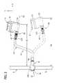
- FIG. 1is a perspective of a clamping apparatus mounting an enteral feeding pump to an IV pole;
- FIG. 2is a left side elevation of FIG. 1 with adjusted position of pump shown in phantom;
- FIG. 3is a rear perspective of the clamping apparatus and medical device with the clamping apparatus exploded;
- FIG. 4is a perspective of a flexible shaft and device clamp of the clamping apparatus
- FIG. 4Ais a side elevation of the flexible shaft
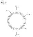
- FIG. 5is an end view of the flexible shaft
- FIG. 6is a section of the flexible shaft taken in the plane including line 6 - 6 of FIG. 5 ;
- FIG. 6Ais an enlarged detail of FIG. 6 showing a sleeve of the flexible shaft
- FIG. 7is an enlarged perspective of the device clamp showing additionally a stem and a sleeve of the clamping apparatus received in the device clamp;
- FIG. 8is a section of the device clamp taken in the plane including line 8 - 8 of FIG. 7 ;
- FIG. 8Ais the section of the device clamp in FIG. 8 with the stem and sleeve shown in phantom;
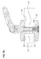
- FIG. 8Bis an enlarged view of a portion of FIG. 8A showing the connection between the device clamp and the stem;
- FIG. 9is a side elevation of a lever and screw attachment of the device clamp.
- FIG. 10is an enlarged detail of FIG. 9 in section to reveal internal threads on the screw;
- FIG. 11is an enlarged perspective of a clamping member of the clamping apparatus
- FIG. 12is a horizontal section of the clamping member of FIG. 11 ;
- FIG. 13is a perspective of the clamping member with the flexible shaft removed and a fragmentary portion of a cylindrical pole received in the clamping member;
- FIG. 13Ais a cross-section taken along the plane including 13 A- 13 A of FIG. 13 ;
- FIG. 14is a perspective similar to FIG. 13 but with a fragmentary portion of a planar table top received in the clamping member;
- FIG. 14Ais a cross-section taken along the plane including 14 A- 14 A of FIG. 14 .
- a powered medical device assembly 1includes a clamping apparatus 3 releasably attached to a support member S to support a medical device 5 on the support member (the reference numerals designating their subjects generally).
- the support member Sis a vertical IV pole having a cylindrical rod R extending up from a stand (not shown) that is commonly used to support medical paraphernalia such as IV bags (not shown) in a hospital or other healthcare environment.
- the clamping apparatus 3is capable of mounting the medical device 5 on support members having other than cylindrical shapes.
- the clamping apparatus 3is configured to allow full range of motion (i.e., six-degrees of freedom of motion) of the medical device 5 relative to the support member S so the medical device can be positioned for better viewing and adjustment.
- the clamping apparatus 3may be more broadly described as “mounting apparatus”, as it will be understood that an apparatus that mounts a medical device without clamping (e.g., including even a permanent attachment) falls within a broader scope of the present invention.
- the medical device 5may be any medical device used in diagnosing, monitoring, or treating a patient.
- the medical device 5is an enteral feeding pump used to regulate the delivery of nutritional fluids to a patient from a container (not shown) but it is understood that the medical device could be any other type of device that is typically mounted on a support.
- the pump 5has a housing 11 , a display screen 13 at the front of the housing for monitoring the operational status of the pump and a control knob 15 for making adjustments to the pump.
- the pump 5has a mounting stem 19 (broadly, “mounting structure”) attached to the back of the housing 11 for releasable attachment to the clamping apparatus 3 .
- the mounting stem 19is cylindrical and extends from the housing 11 . It is understood that the pump 5 may be battery operated or may have a power cord (not shown) connection. The pump may be powered in any suitable manner, such as by fluid or air power. It is envisioned that the pump 5 may also be fluid (e.g., air) powered.
- the clamping apparatus 3includes a clamp, generally indicated 37 , having a clamping member, generally indicated 41 , for releasable attachment of the assembly 1 to the support member S and a securing rod 51 releasably attached to the clamping member for attaching the apparatus to the IV pole.
- the clamping apparatus 3further includes a flexible shaft, generally indicated 43 , attached to the clamping member 41 at a first end 45 and releasably attached to the medical device 5 at a second end 47 through a sleeve 97 .
- the flexible shaft 43is selectively configurable while connected to the pump 5 to allow the pump to have complete freedom of motion relative to the support member S.
- the complete freedom of motion of the pump 5 relative to the support member Sincludes translation of the pump in any of the three dimensions (e.g., x, y, and z-axis) relative to the support as well as rotation or the ability to change the angle of orientation of the pump relative to any of the three axes so that the pump has six degrees of freedom of motion relative to the support. Moreover, once moved the clamping apparatus 3 retains the medical device 5 in its new selected position.
- the flexible shaft 43has a generally tubular body, generally indicated 61 , with an internally threaded bushing 63 mounted on the body at the first end 45 of the shaft and a device clamp, generally indicated 65 , mounted on the body at the second end 47 of the shaft.
- the tubular body 61includes a coil spring, generally indicated 69 , having a plurality of coils 71 extending from the first end 45 to the second end 47 of the shaft 43 .
- a stiffener 75is disposed between the coils 71 to provide stiffness to the flexible shaft 43 and allow the shaft to be set in a stationary position when bent.
- the stiffener 75comprises a wire having a triangular cross-section but it is understood that the stiffener may have other shapes.
- the stiffener 75is pliable to allow the spring 69 to bend and twist in any direction but provides sufficient resistance to prevent the spring from returning to its original position and shape.
- a sheath 77covers the spring 69 and the stiffener 75 to provide a thin outer layer for the flexible shaft 43 .
- the sheath 77may be made from plastic, rubber, vinyl, or any other flexible material.
- the flexible shaft 43may include a tube stiffener made out of a rigid material (e.g. copper, plastic, etc.) or an internal stiffener received through the coil spring without departing from the scope of the invention.
- the threaded bushing 63 mounted on the first end 45 of the flexible shaft 43has a threaded axial bore 81 at its outer end that opens to an axial cavity 85 at its inner end that receives the spring 69 and the stiffener 75 of the flexible shaft 43 .
- the threaded bushing 63includes a collar 87 having an external surface 89 of the flexible shaft 43 covered by the sheath 77 that may be grasped for connecting the flexible shaft 43 to the clamping member 41 .
- the outer axial surface of the bushinghas a rectangular protrusion 93 slightly greater in width than the diameter of the threaded bore 81 .
- the sleeve 97has a first annular recess 141 which will be explained later in greater detail.
- the device clamp 65is an intermediate connector for rotational and releasable connection between the flexible shaft 43 and the stem 19 of the pump 5 .
- the device clamp 65includes a clamp collar 99 having a first (top) clamp element 101 and a second (bottom) clamp element 103 .
- the first clamp element 101has an opening 105 therein.
- the opening 105is shaped like a counterbore and therefore also includes a first shoulder 107 .
- the second clamp element 103has a threaded, counterbore opening 109 with a second shoulder 111 .
- the device clamp 65also includes an adjustment member, indicated generally at 113 .
- the adjustment membercomprises of a lever 115 and a screw 117 ( FIG. 8 ).
- the lever 115is rigidly attached to the screw 117 by a threaded fastener 119 .
- the screwcomprises a head 121 and a shank 122 including a threaded end portion 123 that has a hole 125 (see, FIG. 10 ).
- the screw 117passes through the opening 105 in the first clamp element 101 and is received in the threaded opening 109 in the second clamp element 103 where the threads on the distal end portion 123 of the shank 122 and the threaded opening in the second clamp element engage.
- the head 121 of the screw 117rests on the first shoulder 107 in the first clamp element 101 acting as a brace for the clamping force between the first clamp element and the second clamp element 103 as will be explained in greater detail below.
- a threaded fastener 127passes through the bottom end of opening 109 in the second clamp element and is threadedly received in the hole 125 in the screw 117 .
- the threaded fastener 127mounts a washer 129 on the free end of the distal end portion 123 of the shank 122 .
- the washer 129has a sufficiently large diameter to engage the second shoulder 111 of the opening 109 in the second clamp element 103 during operation of the connector 65 .
- a compression spring 131is positioned around the shank 122 of the screw 117 and its opposite ends bear against the first clamp element 101 and the second clamp element 103 , holding the spring in place within the device clamp 65 .
- the compression spring 131biases the first and second clamp elements 101 , 103 away from each other.
- a first receptacle 133includes a first annular lip 137 (broadly, “a shaft catch”) projecting radially inward and extending substantially continuously around the receptacle.
- a second receptacle 135includes a second (shallow) annular lip 139 (broadly, “a device catch”), smaller than the first annular lip 137 but also projecting radially inward and extending substantially continuously around the receptacle.
- the first receptacle 133is sized and shaped for receiving the sleeve 97 on the second end 47 of the flexible shaft 43
- the second receptacle 135is sized and shaped for receiving the stem 19 in the pump 5
- the sleeve 97 of the flexible shaft 43includes the first annular recess 141 .
- the annular lip 137extends into the annular recess 141 allowing the first receptacle to resist withdrawal of the flexible shaft 43 .
- the stem 19 in the pump 5has a second annular recess 143 .
- the second annular lip 139extends into the second annular recess 143 providing a mechanical interlock and allowing the second receptacle to resist withdrawal of the pump 5 (see, FIG. 8B ).
- the device clamp 65operates in three positions. In a first position, the threaded connection between the screw 117 and the second clamp element 103 is at its tightest. In this position, the first and second clamp elements 101 , 103 are closer together so that the elements bear against the sleeve 97 of the flexible shaft 43 and the stem 19 of the pump 5 . The two clamp elements 101 , 103 fictionally engage the flexible shaft 43 and stem 19 , thus prohibiting relative rotation between the flexible shaft 43 , clamp collar 99 and the pump 5 .
- the lever 115is further turned a sufficient additional degree from the second position to loosen the thread connection between the screw 117 and the second clamp element 103 such that the first and second clamp elements move further apart from one another aided by the bias of the spring 131 .
- the second annular lip 139clears the second annular recess 143 . This will result in the complete removal of all circumferential interference between the second annular lip 139 and the stem 19 permitting the pump 5 to move freely into and out of the second receptacle 135 .
- This positionwill allow the user to handle the pump 5 free from connection to the flexible shaft 43 or allow the pump 5 to be changed out for another device.
- the first annular lip 131will still extend into the first annular recess 141 maintaining connection between the flexible shaft 43 and the device clamp 65 .
- the clamping member 41is generally C-shaped and has an inner surface, generally indicated 161 , for contact with the IV pole or other support member S, an opening 163 for receiving the support member, and an outer surface generally indicated at 165 . It is to be understood that clamping members (not shown) having configurations other than described herein may be used within the scope of the present invention. Moreover, the clamping member may be eliminated entirely without departing from the scope of the present invention. Referring to FIG. 12 , the clamping member 41 has an upper portion 169 at the top (as oriented in FIG. 12 ) of the clamping member intersecting a middle portion 171 generally at a right angle.
- the inner surface 161 on the middle portion 171has a recess 175 .
- a threaded hole 177 of the clamping member 41passes through the upper portion 169 and a cylindrical, non-threaded opening 179 passes through the recess 175 in middle portion 171 .
- the middle portionhas projecting walls 184 spaced to define a recess 185 that is sized to receive the rectangular protrusion 93 ( FIG. 3 ) on the threaded bushing 63 at the first end 45 of the flexible shaft 43 when the flexible shaft is connected to the clamping member 41 .
- a first lower portion 187 of the clamping member 41intersects the middle portion 171 generally at right angles.
- a second lower portion 190is downwardly bent relative to the first lower portion 187 so that the first lower portion and the second lower portion meet at a bend 191 having an angle less than 90 degrees.
- a third lower portion 193is upwardly bent relative to the second lower portion 190 so that the second and third lower portions meet at a lower bend 195 in the clamping member 41 .
- the second and third lower portions 190 , 193define a “V” to receive an IV pole or support member S (see, FIG. 13 ).
- a fourth lower portion 197is downwardly bent relative to the third lower portion 193 so that the third and fourth lower portions meet at a bend 199 .
- a portion of the inner surface 161 on the fourth lower portion 197 that faces the upper portion 169is disposed substantially along the same plane as a corresponding surface portion of the first lower portion 187 .
- the first lower portion 187has two roughly semi-cylindrical arms 205 , 207 on its outer surface that form a cylindrical recess 211 in the first lower portion.
- the cylindrical recess 211provides structure for holding for an AC power adapter cord (not shown) when the cord is not in use.
- the two arms 205 , 207are separated by an axial slot 213 that allows the power adapter cord or other cord of the pump 5 to be received in the recess 211 .
- the flexible shaft 43is attached to the clamping member 41 by a threaded bolt 261 or other fastener that is received through the opening 179 in the recess 175 on the middle portion 171 of the clamping member and is in threaded engagement with the internally threaded bushing 63 on the first end 45 of the flexible shaft.
- the recess 175is configured to receive the head of the bolt 261 so that the head does not interfere with the support member S when the clamping member 41 is connected to the flexible shaft 43 .
- the recess 185 on the middle portion of the clamping memberreceives the protrusion 93 on the threaded bushing.
- the engagement of the protrusion 93 on the threaded bushing 63 with the walls 184prevents the bushing from rotating when the threaded fastener 261 is threadably advanced into the bushing.
- the threaded connection between the flexible shaft 43 and the clamping member 41allows the flexible shaft and the clamping member to be disassembled and interchanged with other parts (e.g., a flexible shaft having a longer or shorter length, a flexible shaft having an increased or decreased stiffness, or a clamping member having a different shape) by removing the threaded fastener 261 .
- the flexible shaft 43may be connected to the clamping member 41 with other attachment mechanisms (e.g., quick-disconnect connector, rivet, etc.) without departing from the scope of this invention.
- the clamping member 41 of the present inventionallows the pump 5 to be mounted on either a cylindrical surface S ( FIGS. 13 and 13A ) or a planar surface PS ( FIGS. 14 and 14A ).
- the pump 5may be conveniently mounted in a healthcare environment on an IV pole, horizontal or vertical bed rail, wheelchair tubing, or other support typical of a hospital or other medical facility.
- the pump 5may be mounted on a table top PS or other structure for use in a home or other setting outside of a medical facility.
- Other suitable support structures for mounting the pump 5include, but are not limited to, powered medical scooters or mobility chairs, multi-parameter carts, doors, tables, cabinets, bed stands, countertops, chairs, medical trays, television trays, and desks.
- the clamping member 41may receive a pole S having a first thickness T 1 ( FIG. 13A ) or a table top PS having a generally planar surface with a thickness T 2 ( FIG. 14A ) that may be greater than or less than the thickness of the pole.
- the clamping apparatus 3may be configured for clamping the medical device 5 to a table top or other planar support member PS.
- the securing rod 51is threadably received through the threaded hole 177 of the clamping member 41 to contact the upper surface US of the table top PS.
- the lower surface LS of the table top PScontacts the inner surface 161 of the first lower portion 187 and fourth lower portion 197 of the clamping member 41 so that the table PS is held in clamped engagement between the securing rod 51 and the clamping member.
- the clamping apparatus 3is secured to the table PS by turning the knob 325 on the securing rod 51 so that the rod engages the upper surface US of the table and urges the lower surface LS of the table into secure contact with first and fourth lower portions 187 , 197 .
- the substantially co-planar relationship of the first and fourth portions 187 , 197provides stability and orients the middle portion 171 generally perpendicular to the upper and lower surfaces US, LS of the table top PS.
- the flexible shaft 43 of the present inventionallows six degrees of freedom of motion of the pump 5 relative to the support member S.
- the pump 5may be mounted in a first position ( FIGS. 1 and 2 ) in which the pump is retained by the flexible shaft 43 in a stationary position so that a point on the housing 11 (e.g., the front of the housing) is a first distance D 1 away from the support.
- the flexible shaft 43may be manipulated so that the pump is moved to a second position (shown in phantom in FIG. 2 ) in which the pump is retained by the flexible shaft in a stationary position so that the point on the housing is a second distance D 2 greater than the first distance D 1 from the support member S.
- the pump 5may be positioned closer to the pole S at the second position such that the distance D 2 is less than the first distance D 1 .
- the pump 5may be tilted up or down about a horizontal axis (e.g., x-axis FIGS. 1 and 2 ) perpendicular to the support S and passing through the pump to allow better viewing of the display screen 13 on the pump.
- the pump 5may be tilted left or right about a vertical axis (e.g., y-axis FIGS. 1 and 2 ) to allow the display screen 13 to be viewed or the controls 15 to be accessed.
- the pump 5may be rotated using the device clamp 65 about the horizontal axis A 2 .
- the device clamp 65helps to prevent the spring 69 of the flexible shaft 43 from being unwound by rotation, which can cause a loss of functionality of the flexible shaft.
- the flexible shaft 43also allows the pump 5 to be moved anywhere along a line intersecting the support S and the pump so that the only factor limiting the position of the pump relative to the support is the length of the flexible shaft.
Landscapes
- Engineering & Computer Science (AREA)
- General Engineering & Computer Science (AREA)
- Mechanical Engineering (AREA)
- Health & Medical Sciences (AREA)
- Biomedical Technology (AREA)
- Heart & Thoracic Surgery (AREA)
- Hematology (AREA)
- Life Sciences & Earth Sciences (AREA)
- Animal Behavior & Ethology (AREA)
- General Health & Medical Sciences (AREA)
- Public Health (AREA)
- Veterinary Medicine (AREA)
- Anesthesiology (AREA)
- Vascular Medicine (AREA)
- Infusion, Injection, And Reservoir Apparatuses (AREA)
- Accommodation For Nursing Or Treatment Tables (AREA)
Abstract
Description
This invention relates generally to the field of support apparatus for medical devices and more particularly to a medical device mounting apparatus having a clamping apparatus.
Medical devices such as enteral feeding pumps are typically attached to an IV pole or other support member by a pole clamp or other attachment device that holds the pump in a fixed position relative to the support member. One existing pole clamp design permits one degree of freedom of motion of the pump relative to the pole by allowing the pump to be rotated or indexed between fixed orientations relative to the IV pole. The indexing requires a substantial portion of the fixture be located on the clamp. Another existing pole clamp design permits two or more degrees of freedom of motion such that the pump may be moved horizontally, vertically, or laterally relative to the IV pole for easier viewing and operation. An example is embodied in co-assigned application Ser. No. 11/138,200 entitled Flexible Clamping Apparatus for Medical Devices filed May 26, 2005, the disclosure of which is incorporated herein by reference.
Furthermore, such existing pole clamps are typically mounted directly on the housing of the pump so that the pump housing is in close proximity to the IV pole. As such, the pumps mounted by conventional pole clamps take up more vertical space on the IV pole that may be needed for other devices and/or medical fluid containers. These existing designs are ill-equipped for moving equipment in and out of the way at bedside as needed when providing medical care. Therefore, a need exists for a simple effective means of releasably securing a pump or similar device to a support while also allowing adjustment of the pump without releasing the pump's connection to the support.
In one aspect of the present invention, a clamping apparatus used in a medical environment to releasably secure a device to a support member generally comprises a flexible shaft having a first end for attachment to the support member and a second end for attachment to the device. A device clamp is adapted to connect the device to the flexible shaft. The device clamp comprises first and second generally opposed clamp elements and a connector interconnecting the first and second clamp elements. The first and second clamp elements define a first receptacle for receiving the second end of the flexible shaft therein and a second receptacle for receiving a mounting structure of the device therein. At least one of the first and second clamp elements defines a device catch in the second receptacle. The connector is selectively moveable between a first position in which the clamp elements are adapted to frictionally engage the second end of the flexible shaft and the mounting structure of the device to resist relative rotation between the flexible shaft, device clamp and device; and a second position in which the clamp elements are relatively farther apart than in the first position and the device catch is position to prevent withdrawal of the mounting structure of the device from the second receptacle thereby permitting the device to be rotated with respect to the flexible shaft without releasing connection to the flexible shaft.
In another aspect, a clamp for use in connecting a medical device to a support generally comprises first and second generally opposed clamp elements and a connector interconnecting the first and second clamp elements. The first and second clamp elements define a first receptacle for receiving an end of the support therein and a second receptacle for receiving a mounting structure of the medical device therein. At least one of the first and second clamp elements defines a device catch in the second receptacle. The connector is selectively movable between a first position in which the clamp elements are adapted to frictionally engage the end of the support and the mounting structure of the device to resist relative rotation between the support, clamp and medical device; and a second position in which the clamp elements are relatively farther apart than in the first position and the device catch is positioned to prevent withdrawal of the mounting structure of the medical device from the second receptacle thereby permitting the device to be rotated with respect to the support without releasing connection to the support.
In yet another aspect, a method of supporting a medical device on a flexible shaft to permit selective rotation of the medical device relative to the flexible shaft without loss of interconnection with the shaft generally comprises rotating a connector to move first and second clamp elements to an open position. Inserting a mounting structure of the medical device into a second receptacle defined by the first and second clamp elements. Then rotating the connector to move the first and second clamp elements to a fully closed position thereby clamping the mounting structure in a receptacle defined by the first and second clamp elements for resisting relative rotation of the mounting structure relative to the flexible shaft. Lastly, loosening the clamp to a position in which the mounting structure and medical device are free to rotate, while the medical device is retained from moving out of the receptacle.
Other objects and features will be in part apparent and in part pointed out hereinafter.
Corresponding reference characters indicate corresponding parts throughout the drawings.
Referring now to the drawings and in particular toFIGS. 1-3 , a poweredmedical device assembly 1 includes aclamping apparatus 3 releasably attached to a support member S to support amedical device 5 on the support member (the reference numerals designating their subjects generally). In the embodiment ofFIG. 1 , the support member S is a vertical IV pole having a cylindrical rod R extending up from a stand (not shown) that is commonly used to support medical paraphernalia such as IV bags (not shown) in a hospital or other healthcare environment. As discussed further below, theclamping apparatus 3 is capable of mounting themedical device 5 on support members having other than cylindrical shapes. Theclamping apparatus 3 is configured to allow full range of motion (i.e., six-degrees of freedom of motion) of themedical device 5 relative to the support member S so the medical device can be positioned for better viewing and adjustment. Theclamping apparatus 3 may be more broadly described as “mounting apparatus”, as it will be understood that an apparatus that mounts a medical device without clamping (e.g., including even a permanent attachment) falls within a broader scope of the present invention.
Themedical device 5 may be any medical device used in diagnosing, monitoring, or treating a patient. In the illustrated embodiment, themedical device 5 is an enteral feeding pump used to regulate the delivery of nutritional fluids to a patient from a container (not shown) but it is understood that the medical device could be any other type of device that is typically mounted on a support. In the illustrated embodiment, thepump 5 has ahousing 11, adisplay screen 13 at the front of the housing for monitoring the operational status of the pump and acontrol knob 15 for making adjustments to the pump. As shown inFIG. 3 , thepump 5 has a mounting stem19 (broadly, “mounting structure”) attached to the back of thehousing 11 for releasable attachment to theclamping apparatus 3. The mountingstem 19 is cylindrical and extends from thehousing 11. It is understood that thepump 5 may be battery operated or may have a power cord (not shown) connection. The pump may be powered in any suitable manner, such as by fluid or air power. It is envisioned that thepump 5 may also be fluid (e.g., air) powered.
Theclamping apparatus 3 includes a clamp, generally indicated37, having a clamping member, generally indicated41, for releasable attachment of theassembly 1 to the support member S and a securingrod 51 releasably attached to the clamping member for attaching the apparatus to the IV pole. Theclamping apparatus 3 further includes a flexible shaft, generally indicated43, attached to the clampingmember 41 at afirst end 45 and releasably attached to themedical device 5 at asecond end 47 through asleeve 97. Theflexible shaft 43 is selectively configurable while connected to thepump 5 to allow the pump to have complete freedom of motion relative to the support member S. The complete freedom of motion of thepump 5 relative to the support member S includes translation of the pump in any of the three dimensions (e.g., x, y, and z-axis) relative to the support as well as rotation or the ability to change the angle of orientation of the pump relative to any of the three axes so that the pump has six degrees of freedom of motion relative to the support. Moreover, once moved theclamping apparatus 3 retains themedical device 5 in its new selected position.
As shown inFIGS. 4 ,4A and6, theflexible shaft 43 has a generally tubular body, generally indicated61, with an internally threadedbushing 63 mounted on the body at thefirst end 45 of the shaft and a device clamp, generally indicated65, mounted on the body at thesecond end 47 of the shaft. As shown inFIG. 6 , thetubular body 61 includes a coil spring, generally indicated69, having a plurality ofcoils 71 extending from thefirst end 45 to thesecond end 47 of theshaft 43. Astiffener 75 is disposed between thecoils 71 to provide stiffness to theflexible shaft 43 and allow the shaft to be set in a stationary position when bent. In the illustrated embodiment, thestiffener 75 comprises a wire having a triangular cross-section but it is understood that the stiffener may have other shapes. Thestiffener 75 is pliable to allow thespring 69 to bend and twist in any direction but provides sufficient resistance to prevent the spring from returning to its original position and shape. Asheath 77 covers thespring 69 and thestiffener 75 to provide a thin outer layer for theflexible shaft 43. Thesheath 77 may be made from plastic, rubber, vinyl, or any other flexible material. It is understood that theflexible shaft 43 may include a tube stiffener made out of a rigid material (e.g. copper, plastic, etc.) or an internal stiffener received through the coil spring without departing from the scope of the invention.
Referring now specifically toFIG. 6 , the threadedbushing 63 mounted on thefirst end 45 of theflexible shaft 43 has a threadedaxial bore 81 at its outer end that opens to anaxial cavity 85 at its inner end that receives thespring 69 and thestiffener 75 of theflexible shaft 43. The threadedbushing 63 includes acollar 87 having anexternal surface 89 of theflexible shaft 43 covered by thesheath 77 that may be grasped for connecting theflexible shaft 43 to the clampingmember 41. As shown inFIG. 3 , the outer axial surface of the bushing has arectangular protrusion 93 slightly greater in width than the diameter of the threaded bore81. At thesecond end 47 of theflexible shaft 43 thesleeve 97 has a firstannular recess 141 which will be explained later in greater detail.
Referring now toFIGS. 7 and 8 , thedevice clamp 65 is an intermediate connector for rotational and releasable connection between theflexible shaft 43 and thestem 19 of thepump 5. Thedevice clamp 65 includes aclamp collar 99 having a first (top)clamp element 101 and a second (bottom)clamp element 103. Thefirst clamp element 101 has anopening 105 therein. Theopening 105 is shaped like a counterbore and therefore also includes afirst shoulder 107. Thesecond clamp element 103 has a threaded, counterbore opening109 with asecond shoulder 111.
Thedevice clamp 65 also includes an adjustment member, indicated generally at113. The adjustment member comprises of alever 115 and a screw117 (FIG. 8 ). Thelever 115 is rigidly attached to thescrew 117 by a threadedfastener 119. The screw comprises ahead 121 and ashank 122 including a threadedend portion 123 that has a hole125 (see,FIG. 10 ). Thescrew 117 passes through theopening 105 in thefirst clamp element 101 and is received in the threadedopening 109 in thesecond clamp element 103 where the threads on thedistal end portion 123 of theshank 122 and the threaded opening in the second clamp element engage. Thehead 121 of thescrew 117 rests on thefirst shoulder 107 in thefirst clamp element 101 acting as a brace for the clamping force between the first clamp element and thesecond clamp element 103 as will be explained in greater detail below.
A threadedfastener 127 passes through the bottom end of opening109 in the second clamp element and is threadedly received in thehole 125 in thescrew 117. The threadedfastener 127 mounts awasher 129 on the free end of thedistal end portion 123 of theshank 122. Thewasher 129 has a sufficiently large diameter to engage thesecond shoulder 111 of theopening 109 in thesecond clamp element 103 during operation of theconnector 65. Acompression spring 131 is positioned around theshank 122 of thescrew 117 and its opposite ends bear against thefirst clamp element 101 and thesecond clamp element 103, holding the spring in place within thedevice clamp 65. Thecompression spring 131 biases the first andsecond clamp elements
At each end of theclamp elements receptacles 133,135 (see,FIG. 8A ). Afirst receptacle 133 includes a first annular lip137 (broadly, “a shaft catch”) projecting radially inward and extending substantially continuously around the receptacle. Asecond receptacle 135 includes a second (shallow) annular lip139 (broadly, “a device catch”), smaller than the firstannular lip 137 but also projecting radially inward and extending substantially continuously around the receptacle. Thefirst receptacle 133 is sized and shaped for receiving thesleeve 97 on thesecond end 47 of theflexible shaft 43, and thesecond receptacle 135 is sized and shaped for receiving thestem 19 in thepump 5. Thesleeve 97 of theflexible shaft 43 includes the firstannular recess 141. When thesleeve 97 is received in thefirst receptacle 133, theannular lip 137 extends into theannular recess 141 allowing the first receptacle to resist withdrawal of theflexible shaft 43. Similarly, thestem 19 in thepump 5 has a secondannular recess 143. When thestem 19 is received in thesecond receptacle 135, the secondannular lip 139 extends into the secondannular recess 143 providing a mechanical interlock and allowing the second receptacle to resist withdrawal of the pump5 (see,FIG. 8B ).
Thedevice clamp 65 operates in three positions. In a first position, the threaded connection between thescrew 117 and thesecond clamp element 103 is at its tightest. In this position, the first andsecond clamp elements sleeve 97 of theflexible shaft 43 and thestem 19 of thepump 5. The twoclamp elements flexible shaft 43 andstem 19, thus prohibiting relative rotation between theflexible shaft 43,clamp collar 99 and thepump 5.
In a second position, thelever 115 is turned a sufficient degree to loosen the thread connection between thescrew 117 and thesecond clamp element 103 so that the first and second clamp elements move apart from one another aided by the bias of thespring 131. This second position will result in a reduction in the frictional force between theclamp collar 99 and thestem 19 permitting thepump 5 to be rotated, within thesecond receptacle 135, with respect to theflexible shaft 43. The firstannular lip 137 in thefirst receptacle 133 will still extend into the firstannular recess 141 on thesleeve 97 thus maintaining connection to theflexible shaft 43. The secondannular lip 139 also retains connection of thepump 5 to theflexible shaft 43 in this position. This allows thepump 5 to be rotated to a desired orientation and then secured in that position by turning thelever 115 in the opposite direction. This will tighten the threaded connection between thescrew 117 and thesecond clamp element 103, thus, restoring the frictional engagement between thecollar 99 and thestem 19. Those skilled in the art will see that as the first and second elements move apart the frictional force will also be reduced between theclamp collar 99 and thesleeve 97 permitting thecollar 99 to rotate in relation to both thepump 5 and theflexible shaft 43. This has the advantage that when theclamp 37 must be attached to a support in an attitude that would otherwise place thelever 115 in a less accessible location theclamp 99 can be rotated around theshaft 43 to place thelever 115 in a more convenient position for operation.
In a third position, thelever 115 is further turned a sufficient additional degree from the second position to loosen the thread connection between thescrew 117 and thesecond clamp element 103 such that the first and second clamp elements move further apart from one another aided by the bias of thespring 131. In this position the secondannular lip 139 clears the secondannular recess 143. This will result in the complete removal of all circumferential interference between the secondannular lip 139 and thestem 19 permitting thepump 5 to move freely into and out of thesecond receptacle 135. This position will allow the user to handle thepump 5 free from connection to theflexible shaft 43 or allow thepump 5 to be changed out for another device. In this third position the firstannular lip 131 will still extend into the firstannular recess 141 maintaining connection between theflexible shaft 43 and thedevice clamp 65.
As shown inFIGS. 11 and 12 , the clampingmember 41 is generally C-shaped and has an inner surface, generally indicated161, for contact with the IV pole or other support member S, anopening 163 for receiving the support member, and an outer surface generally indicated at165. It is to be understood that clamping members (not shown) having configurations other than described herein may be used within the scope of the present invention. Moreover, the clamping member may be eliminated entirely without departing from the scope of the present invention. Referring toFIG. 12 , the clampingmember 41 has anupper portion 169 at the top (as oriented inFIG. 12 ) of the clamping member intersecting amiddle portion 171 generally at a right angle. Theinner surface 161 on themiddle portion 171 has arecess 175. A threadedhole 177 of the clampingmember 41 passes through theupper portion 169 and a cylindrical,non-threaded opening 179 passes through therecess 175 inmiddle portion 171. The middle portion has projectingwalls 184 spaced to define arecess 185 that is sized to receive the rectangular protrusion93 (FIG. 3 ) on the threadedbushing 63 at thefirst end 45 of theflexible shaft 43 when the flexible shaft is connected to the clampingmember 41.
A firstlower portion 187 of the clampingmember 41 intersects themiddle portion 171 generally at right angles. A secondlower portion 190 is downwardly bent relative to the firstlower portion 187 so that the first lower portion and the second lower portion meet at abend 191 having an angle less than 90 degrees. A thirdlower portion 193 is upwardly bent relative to the secondlower portion 190 so that the second and third lower portions meet at alower bend 195 in the clampingmember 41. The second and thirdlower portions FIG. 13 ). A fourthlower portion 197 is downwardly bent relative to the thirdlower portion 193 so that the third and fourth lower portions meet at abend 199. A portion of theinner surface 161 on the fourthlower portion 197 that faces theupper portion 169 is disposed substantially along the same plane as a corresponding surface portion of the firstlower portion 187.
As shown inFIGS. 11 and 12 , the firstlower portion 187 has two roughlysemi-cylindrical arms cylindrical recess 211 in the first lower portion. Thecylindrical recess 211 provides structure for holding for an AC power adapter cord (not shown) when the cord is not in use. The twoarms axial slot 213 that allows the power adapter cord or other cord of thepump 5 to be received in therecess 211.
As shown inFIG. 3 , theflexible shaft 43 is attached to the clampingmember 41 by a threadedbolt 261 or other fastener that is received through theopening 179 in therecess 175 on themiddle portion 171 of the clamping member and is in threaded engagement with the internally threadedbushing 63 on thefirst end 45 of the flexible shaft. Therecess 175 is configured to receive the head of thebolt 261 so that the head does not interfere with the support member S when the clampingmember 41 is connected to theflexible shaft 43. When the axially outer surface of the threadedbushing 63 on theflexible shaft 43 abuts theouter surface 165 of themiddle portion 171 of the clampingmember 41, therecess 185 on the middle portion of the clamping member receives theprotrusion 93 on the threaded bushing. The engagement of theprotrusion 93 on the threadedbushing 63 with thewalls 184 prevents the bushing from rotating when the threadedfastener 261 is threadably advanced into the bushing. The threaded connection between theflexible shaft 43 and the clampingmember 41 allows the flexible shaft and the clamping member to be disassembled and interchanged with other parts (e.g., a flexible shaft having a longer or shorter length, a flexible shaft having an increased or decreased stiffness, or a clamping member having a different shape) by removing the threadedfastener 261. It is understood that theflexible shaft 43 may be connected to the clampingmember 41 with other attachment mechanisms (e.g., quick-disconnect connector, rivet, etc.) without departing from the scope of this invention.
It is understood that the clampingmember 41 of the present invention allows thepump 5 to be mounted on either a cylindrical surface S (FIGS. 13 and 13A ) or a planar surface PS (FIGS. 14 and 14A ). Thus thepump 5 may be conveniently mounted in a healthcare environment on an IV pole, horizontal or vertical bed rail, wheelchair tubing, or other support typical of a hospital or other medical facility. In addition, thepump 5 may be mounted on a table top PS or other structure for use in a home or other setting outside of a medical facility. Other suitable support structures for mounting thepump 5 include, but are not limited to, powered medical scooters or mobility chairs, multi-parameter carts, doors, tables, cabinets, bed stands, countertops, chairs, medical trays, television trays, and desks. Further, the clampingmember 41 may receive a pole S having a first thickness T1 (FIG. 13A ) or a table top PS having a generally planar surface with a thickness T2 (FIG. 14A ) that may be greater than or less than the thickness of the pole.
As shown inFIGS. 14 and 14A , theclamping apparatus 3 may be configured for clamping themedical device 5 to a table top or other planar support member PS. In this arrangement, the securingrod 51 is threadably received through the threadedhole 177 of the clampingmember 41 to contact the upper surface US of the table top PS. The lower surface LS of the table top PS contacts theinner surface 161 of the firstlower portion 187 and fourthlower portion 197 of the clampingmember 41 so that the table PS is held in clamped engagement between the securingrod 51 and the clamping member. Theclamping apparatus 3 is secured to the table PS by turning theknob 325 on the securingrod 51 so that the rod engages the upper surface US of the table and urges the lower surface LS of the table into secure contact with first and fourthlower portions fourth portions middle portion 171 generally perpendicular to the upper and lower surfaces US, LS of the table top PS.
Theflexible shaft 43 of the present invention allows six degrees of freedom of motion of thepump 5 relative to the support member S. Thepump 5 may be mounted in a first position (FIGS. 1 and 2 ) in which the pump is retained by theflexible shaft 43 in a stationary position so that a point on the housing11 (e.g., the front of the housing) is a first distance D1 away from the support. By applying a force to thehousing 11 of thepump 5, theflexible shaft 43 may be manipulated so that the pump is moved to a second position (shown in phantom inFIG. 2 ) in which the pump is retained by the flexible shaft in a stationary position so that the point on the housing is a second distance D2 greater than the first distance D1 from the support member S. It is understood that thepump 5 may be positioned closer to the pole S at the second position such that the distance D2 is less than the first distance D1. Also, thepump 5 may be tilted up or down about a horizontal axis (e.g., x-axisFIGS. 1 and 2 ) perpendicular to the support S and passing through the pump to allow better viewing of thedisplay screen 13 on the pump. Further, thepump 5 may be tilted left or right about a vertical axis (e.g., y-axisFIGS. 1 and 2 ) to allow thedisplay screen 13 to be viewed or thecontrols 15 to be accessed. Thepump 5 may be rotated using thedevice clamp 65 about the horizontal axis A2. Thedevice clamp 65 helps to prevent thespring 69 of theflexible shaft 43 from being unwound by rotation, which can cause a loss of functionality of the flexible shaft. Theflexible shaft 43 also allows thepump 5 to be moved anywhere along a line intersecting the support S and the pump so that the only factor limiting the position of the pump relative to the support is the length of the flexible shaft.
Having described the invention in detail, it will be apparent that modifications and variations are possible without departing from the scope of the invention defined in the appended claims.
When introducing elements of the present invention or the preferred embodiments(s) thereof, the articles “a”, “an”, “the” and “said” are intended to mean that there are one or more of the elements. The terms “comprising”, “including” and “having” are intended to be inclusive and mean that there may be additional elements other than the listed elements.
In view of the above, it will be seen that the several objects of the invention are achieved and other advantageous results attained.
As various changes could be made in the above construction without departing from the scope of the invention, it is intended that all matter contained in the above description and shown in the accompanying drawings shall be interpreted as illustrative and not in a limiting sense.
Claims (25)
1. A clamping apparatus for use in a medical environment to releasably secure a device to a support member, the clamping apparatus comprising:
a flexible shaft having a first end for attachment to the support member and a second end for attachment to the device;
a device clamp adapted to connect the device to the flexible shaft, the device clamp comprising first and second generally opposed clamp elements and a connector interconnecting the first and second clamp elements, the first and second clamp elements defining a first receptacle for receiving the second end of the flexible shaft therein and a second receptacle for receiving a mounting structure of the device therein, at least one of the first and second clamp elements defining a device catch in the second receptacle, the connector being selectively movable between a first position in which the clamp elements are adapted to frictionally engage the second end of the flexible shaft and the mounting structure of the device to resist relative rotation between the flexible shaft, device clamp and device, and a second position in which the clamp elements are relatively farther apart than in the first position and the device catch is positioned to prevent withdrawal of the mounting structure of the device from the second receptacle thereby permitting the device to be rotated with respect to the flexible shaft without releasing connection to the flexible shaft.
2. A clamping apparatus as set forth inclaim 1 wherein the device catch comprises a generally annular lip defined by the first and second clamp elements projecting radially inwardly into the second receptacle.
3. A clamping apparatus as set forth inclaim 2 wherein the lip extends substantially continuously about the second receptacle.
4. A clamping apparatus as set forth inclaim 1 wherein the clamp comprises a shaft catch defined by at least one of the first and second clamp elements in the first receptacle, the shaft catch being positioned to resist withdrawal of the flexible shaft.
5. A clamping apparatus as set forth inclaim 4 wherein the device catch projects into the second receptacle a distance less than the shaft catch projects into the first receptacle.
6. A clamping apparatus as set forth inclaim 1 wherein the device catch comprises an annular lip projecting into the first receptacle, and wherein the second end of the flexible shaft has a recess therein for receiving the annular lip when the second end of the flexible shaft is received in the first receptacle.
7. A clamping apparatus as set forth inclaim 6 wherein the recess extends circumferentially around a longitudinal axis of the flexible shaft.
8. A clamping apparatus as set forth inclaim 7 wherein the recess is located inwardly from a termination of the second end of the flexible shaft thereby defining a head receivable in the first receptacle of the device clamp and generally axially opposed to the annular lip in the first and second positions of the connector to capture the second end of the flexible shaft in the first receptacle.
9. A clamping apparatus as set forth inclaim 1 wherein the connector is further selectively movable to a third position in which the mounting structure of the device is freely movable into and out of the second receptacle and the second end of the flexible shaft remains captured by the shaft catch in the first receptacle.
10. A clamping apparatus as set forth inclaim 1 wherein the connector comprises a screw including a head and a shank, the first clamp element having a bore and the second clamp element having a threaded bore, the shank extending through the bore in the first clamp element and being threadably received in the threaded bore of the second clamp element so that upon rotation of the screw the first and second clamp elements are moved between the first and second positions.
11. A clamping apparatus as set forth inclaim 10 wherein the shank is sized and shaped to prevent withdrawal of the shank from the second clamp element thereby retaining the interconnection of the first and second clamp elements.
12. A clamping apparatus as set forth inclaim 11 wherein the shank further comprises a washer mounted on a free end of the shank, the washer having a diameter greater than a diameter of the bore in the second clamp element.
13. A clamping apparatus as set forth inclaim 10 wherein the head includes a lever projecting generally radially outwardly from the shank for rotating the screw.
14. A clamping apparatus as set forth inclaim 13 further comprising a compression spring arranged for biasing the first and second clamp elements away from each other.
15. A clamping apparatus as set forth inclaim 1 further comprising a clamping member for connecting the flexible shaft to the support member, the clamping member having a portions lying generally in a coplanar relation and separated by a portion defining a non-coplanar, recessed section adapted to receive cylindrical structure therein.
16. A clamp for use in connecting a medical device to a support, the clamp comprising:
first and second generally opposed clamp elements; and
a connector interconnecting the first and second clamp elements;
the first and second clamp elements defining a first receptacle for receiving an end of the support therein and a second receptacle for receiving a mounting structure of the medical device therein, at least one of the first and second clamp elements defining a device catch in the second receptacle, the connector being selectively movable between a first position in which the clamp elements are adapted to frictionally engage the end of the support and the mounting structure of the device to resist relative rotation between the support, clamp and medical device, and a second position in which the clamp elements are relatively farther apart than in the first position and the device catch is positioned to prevent withdrawal of mounting structure of the medical device from the second receptacle thereby permitting the device to be rotated with respect to the support without releasing connection to the support.
17. A clamp as set forth inclaim 16 wherein the device catch comprises a generally annular lip defined by the first and second clamp elements projecting radially inwardly into the second receptacle.
18. A clamp as set forth inclaim 17 wherein the lip extends substantially continuously about the second receptacle.
19. A clamp as set forth inclaim 16 further comprising a support catch defined by at least one of the first and second clamp elements in the first receptacle, the device catch being positioned to resist withdrawal of the support in the second position of the clamp elements.
20. A clamping apparatus as set forth inclaim 19 wherein the device catch projects into the second receptacle a distance less than the support catch projects into the first receptacle.
21. A clamp as set forth inclaim 16 wherein the connector is further selectively movable to a third position in which the mounting structure of the medical device is freely movable into and out of the second receptacle and the end of the support remains captured by the support catch in the first receptacle.
22. A clamp as set forth inclaim 16 wherein the connector comprises a screw including a head and a shank, the first clamp element having a bore and the second clamp element having a threaded bore, the shank extending through the bore in the first clamp element and being threadably received in the threaded bore of the second clamp element so that upon rotation of the screw the first and second clamp elements are moved between the first and second positions.
23. A clamp as set forth inclaim 20 wherein the shank is sized and shaped to prevent withdrawal of the shank from the second clamp element thereby retaining the interconnection of the first and second clamp elements.
24. A clamp as set forth inclaim 23 wherein the shank further comprises a washer mounted on a free end of the shank, the washer having a diameter greater than a diameter of the bore in the second clamp element.
25. A method of supporting a medical device on a flexible shaft to permit selective rotation of the medical device relative to the flexible shaft without loss of interconnection with the flexible shaft, the method comprising:
rotating a connector to move first and second clamp elements to an open position;
inserting a mounting structure of the medical device into a receptacle defined by the first and second clamp elements;
rotating the connector to move the first and second clamp elements to a fully closed position thereby clamping the flexible shaft and mounting structure for resisting relative rotation of the mounting structure relative to the flexible shaft;
loosening the clamp to a position in which the mounting structure and medical device are free to rotate, while the medical device is retained from moving out of the receptacle.
Priority Applications (5)
| Application Number | Priority Date | Filing Date | Title |
|---|---|---|---|
| US12/055,161US7546993B1 (en) | 2008-03-25 | 2008-03-25 | Flexible clamping apparatus for medical devices |
| CA002659927ACA2659927A1 (en) | 2008-03-25 | 2009-03-24 | Flexible clamping apparatus for medical devices |
| JP2009073430AJP2009233331A (en) | 2008-03-25 | 2009-03-25 | Flexible fastening device for medical equipment |
| AU2009201182AAU2009201182B2 (en) | 2008-03-25 | 2009-03-25 | Flexible clamping apparatus for medical devices |
| EP09156149AEP2105650A3 (en) | 2008-03-25 | 2009-03-25 | Flexible clamping apparatus for medical devices |
Applications Claiming Priority (1)
| Application Number | Priority Date | Filing Date | Title |
|---|---|---|---|
| US12/055,161US7546993B1 (en) | 2008-03-25 | 2008-03-25 | Flexible clamping apparatus for medical devices |
Publications (1)
| Publication Number | Publication Date |
|---|---|
| US7546993B1true US7546993B1 (en) | 2009-06-16 |
Family
ID=40748543
Family Applications (1)
| Application Number | Title | Priority Date | Filing Date |
|---|---|---|---|
| US12/055,161ActiveUS7546993B1 (en) | 2008-03-25 | 2008-03-25 | Flexible clamping apparatus for medical devices |
Country Status (5)
| Country | Link |
|---|---|
| US (1) | US7546993B1 (en) |
| EP (1) | EP2105650A3 (en) |
| JP (1) | JP2009233331A (en) |
| AU (1) | AU2009201182B2 (en) |
| CA (1) | CA2659927A1 (en) |
Cited By (48)
| Publication number | Priority date | Publication date | Assignee | Title |
|---|---|---|---|---|
| US20070185376A1 (en)* | 2002-03-11 | 2007-08-09 | Wilson Roger F | System and method for positioning a laparoscopic device |
| US20090200443A1 (en)* | 2008-02-13 | 2009-08-13 | Hilti Aktiengesellschaft | Mounting device for securing plate-shaped elements |
| US20090247819A1 (en)* | 2004-04-02 | 2009-10-01 | Wilson Roger F | System and method for positioning a laparoscopic device |
| US20100012798A1 (en)* | 2008-07-16 | 2010-01-21 | Stefanie Blum | Adaptor for fixing a medical apparatus |
| US20100148020A1 (en)* | 2007-03-22 | 2010-06-17 | Colebrook Bosson Saunders Products Ltd. | Flat-screen monitor support |
| US20100301188A1 (en)* | 2009-05-29 | 2010-12-02 | Erik Schimelfenyg | Apparatus for Holding an Ebook Reader |
| US20110192951A1 (en)* | 2010-02-10 | 2011-08-11 | Gerard R Gooch | Portable platform for imaging device |
| US20110302750A1 (en)* | 2010-06-14 | 2011-12-15 | Bush Industries, Inc. | No Tools Quick Assembly Surface Fastening System |
| US20120091307A1 (en)* | 2010-10-13 | 2012-04-19 | Debra Haynes | Stand and method for hands free reading and viewing |
| US20130299661A1 (en)* | 2012-05-11 | 2013-11-14 | B. Braun Avitum Ag | Medical device for extracorporal treatment of blood with filter holder |
| US20140013602A1 (en)* | 2008-12-31 | 2014-01-16 | Medtronic, Inc. | Semi-Rigid Annuloplasty Ring and Band |
| CN103591425A (en)* | 2013-11-15 | 2014-02-19 | 迈柯唯医疗设备(苏州)有限公司 | Movable type accessory fixing device applied to medical crane |
| US20140110549A1 (en)* | 2012-10-23 | 2014-04-24 | Michael Chau-Lun CHANG | Protective sheath working with a fixer for handheld, portable, mobile devices |
| US20140110544A1 (en)* | 2012-10-23 | 2014-04-24 | Michael Chau-Lun CHANG | Fixer for handheld, portable, mobile device |
| CN103989529A (en)* | 2014-06-10 | 2014-08-20 | 迈柯唯医疗设备(苏州)有限公司 | Fast transfer device for medical tower crane |
| US20140231605A1 (en)* | 2013-02-19 | 2014-08-21 | Gary L. Sharpe | Multi-functional clamp |
| EP2769691A1 (en) | 2013-02-25 | 2014-08-27 | Covidien LP | Flexible access assembly |
| CN104013469A (en)* | 2014-06-10 | 2014-09-03 | 迈柯唯医疗设备(苏州)有限公司 | Fast linkage device for medical tower crane |
| CN104271069A (en)* | 2012-04-23 | 2015-01-07 | 泰尔茂株式会社 | Medical apparatus rack |
| US20150090849A1 (en)* | 2013-09-30 | 2015-04-02 | Covidien Lp | Medical device supporting apparatus |
| CN104565747A (en)* | 2015-01-15 | 2015-04-29 | 浙江大学 | Clamping type flat bracket |
| US20150238377A1 (en)* | 2014-02-21 | 2015-08-27 | Wali Muhammad | Patient Bedside System Support Device |
| US20150297826A1 (en)* | 2014-04-18 | 2015-10-22 | Regents Of The University Of Minnesota | Intravenous line lifter devices, systems and methods |
| US20160136339A1 (en)* | 2013-03-14 | 2016-05-19 | Smith & Nephew Inc. | Systems and methods for applying reduced pressure therapy |
| CN106859772A (en)* | 2016-12-20 | 2017-06-20 | 武汉维斯第医用科技股份有限公司 | For the fixture being fixed to Medical Devices above horizontal or vertical bar |
| US20170290633A1 (en)* | 2013-07-18 | 2017-10-12 | Variety Children's Hospital d/b/a Nicklaus Children's Hospital | Portable cardiopulmonary support cart systems |
| US20180003338A1 (en)* | 2015-03-20 | 2018-01-04 | 4th DIMENSION DEVELOPMENTS PTY LTD | Device for holding and supporting articles |
| US10188573B2 (en) | 2014-11-05 | 2019-01-29 | Allen Medical Systems, Inc. | Boot stirrup |
| US10302248B2 (en)* | 2015-11-16 | 2019-05-28 | Frank Steele Arnold, Iii | Universal canopy suspension system for multiple functioning embodiments |
| CN110573109A (en)* | 2017-03-31 | 2019-12-13 | 乔伊马克斯有限责任公司 | Medical fixing device and medical equipment |
| US10610624B2 (en) | 2013-03-14 | 2020-04-07 | Smith & Nephew, Inc. | Reduced pressure therapy blockage detection |
| US20210080054A1 (en)* | 2018-06-19 | 2021-03-18 | Potrero Medical, Inc. | Equipment adaptor assembly and equipment stand |
| US10959895B2 (en)* | 2017-04-13 | 2021-03-30 | Cadwell Laboratories, Inc. | Systems and methods for mounting medical equipment |
| US11026627B2 (en) | 2013-03-15 | 2021-06-08 | Cadwell Laboratories, Inc. | Surgical instruments for determining a location of a nerve during a procedure |
| US11177610B2 (en) | 2017-01-23 | 2021-11-16 | Cadwell Laboratories, ino. | Neuromonitoring connection system |
| US11253182B2 (en) | 2018-05-04 | 2022-02-22 | Cadwell Laboratories, Inc. | Apparatus and method for polyphasic multi-output constant-current and constant-voltage neurophysiological stimulation |
| US11320065B2 (en)* | 2019-04-15 | 2022-05-03 | Neotech Products Llc | Tubing and cable organizing device |
| US11443649B2 (en) | 2018-06-29 | 2022-09-13 | Cadwell Laboratories, Inc. | Neurophysiological monitoring training simulator |
| US20220349520A1 (en)* | 2020-04-29 | 2022-11-03 | Canadian Tire Corporation, Limited | Organizational systems and components |
| DE102021134253B3 (en) | 2021-12-03 | 2022-12-29 | Medizintechnik Sattler Gmbh | quick release clamp |
| US20230096795A1 (en)* | 2020-02-28 | 2023-03-30 | Technologies Cgc Inc. | Coupling systems for releasably coupling equipment to a patient transport systems |
| US11674635B1 (en) | 2020-01-13 | 2023-06-13 | Adaptive Creations Group, Inc. | Support device |
| US20230346510A1 (en)* | 2021-01-26 | 2023-11-02 | Potrero Medical, Inc. | Equipment adaptor assembly and equipment stand |
| US11992339B2 (en) | 2018-05-04 | 2024-05-28 | Cadwell Laboratories, Inc. | Systems and methods for dynamic neurophysiological stimulation |
| US12052838B2 (en) | 2021-07-22 | 2024-07-30 | Qisda Corporation | Display |
| US12072060B2 (en)* | 2022-01-24 | 2024-08-27 | Qisda Corporation | Fixing module and display device using the same |
| US12310904B2 (en) | 2017-04-13 | 2025-05-27 | Cadwell Laboratories, Inc. | Systems and methods for mounting medical equipment |
| USD1080364S1 (en)* | 2020-10-30 | 2025-06-24 | Canadian Tire Corporation, Limited | Accessory for organizational system |
Families Citing this family (6)
| Publication number | Priority date | Publication date | Assignee | Title |
|---|---|---|---|---|
| CN102562743A (en)* | 2010-12-31 | 2012-07-11 | 海洋王照明科技股份有限公司 | Lifting rod connecting structure and lifting rod |
| CN103363470B (en)* | 2012-03-29 | 2016-12-14 | 海洋王照明科技股份有限公司 | Lamp lifting rod tightening device and use the light fixture of this tightening device |
| JP7242198B2 (en)* | 2017-05-31 | 2023-03-20 | フクダ電子株式会社 | Defibrillation systems and connecting devices in defibrillation systems |
| JP6727503B1 (en) | 2019-10-07 | 2020-07-22 | 泉工医科工業株式会社 | Medical device fixing system |
| JP6994491B2 (en)* | 2019-11-07 | 2022-02-04 | タキゲン製造株式会社 | Connector |
| CN111457230A (en)* | 2020-04-02 | 2020-07-28 | 长沙巨翊医疗科技有限公司 | Equipment back clip with ball plunger as main body of rotating mechanism |
Citations (133)
| Publication number | Priority date | Publication date | Assignee | Title |
|---|---|---|---|---|
| US184957A (en) | 1876-12-05 | Improvement in clamps for quilting-frames | ||
| US252969A (en) | 1882-01-31 | Belt-tightener | ||
| US291248A (en) | 1884-01-01 | Roofing-clamp | ||
| US989893A (en) | 1907-12-26 | 1911-04-18 | Thomas Brick | Work-holder for machine-tools. |
| US1059217A (en) | 1912-08-31 | 1913-04-15 | Knut Rudy | Lamp-bracket. |
| US1066357A (en) | 1912-12-12 | 1913-07-01 | Welsbach Light Co | Clamping device or jig. |
| US1160103A (en) | 1914-10-07 | 1915-11-09 | Charles J Miller | Carpenter's tool. |
| US1403863A (en) | 1920-08-16 | 1922-01-17 | Richard T Peat | Portable and adjustable lamp holder |
| US1749491A (en) | 1927-03-26 | 1930-03-04 | Kokay Stephen | Clamp |
| US2101317A (en) | 1935-08-12 | 1937-12-07 | Mclaughlin John J | Clamping device |
| US2116263A (en) | 1937-03-29 | 1938-05-03 | William J Harbaugh | Multiple purpose welding jig |
| US2269790A (en)* | 1938-08-31 | 1942-01-13 | Central Scient Co | Clamp |
| US2322107A (en) | 1941-01-16 | 1943-06-15 | Willard H Seiffert | Clamping means |
| US2448402A (en) | 1945-01-29 | 1948-08-31 | Brian Jones M | Hot wire clamp |
| US2638301A (en) | 1947-01-28 | 1953-05-12 | Donald M Smith | Attachment structure for laboratory clamps |
| US2756789A (en) | 1954-04-29 | 1956-07-31 | Kraus Kermit | Adjustable interconnected multiple clamping device |
| US2867003A (en) | 1956-02-13 | 1959-01-06 | Sierracin Corp | Apparatus for casting plastic sheets |
| US2945946A (en) | 1957-07-22 | 1960-07-19 | Dillon W Moffatt | Lamp |
| US3268853A (en) | 1964-05-20 | 1966-08-23 | Alvin J Noker | Quick connect electrical grounding rod clamp |
| US3442478A (en) | 1967-06-20 | 1969-05-06 | Nicolas Parapetti | Universally adjustable dial indicator holder |
| US3803012A (en) | 1972-03-09 | 1974-04-09 | American Smelting Refining | Cathodic protection anode clamp assembly |
| US3883128A (en) | 1974-02-25 | 1975-05-13 | Ralph J Breese | Universally adjustable clamp |
| US4120130A (en)* | 1976-09-20 | 1978-10-17 | Felix Puschkarski | Clamping device |
| US4164344A (en) | 1976-12-30 | 1979-08-14 | Deragne Maurice M | Hydraulic clamping apparatus |
| US4262872A (en) | 1979-02-28 | 1981-04-21 | American Hospital Supply Corporation | Collapsible pole assembly |
| US4365792A (en) | 1980-08-26 | 1982-12-28 | Johns Consolidated Limited | Hydraulic mould clamp |
| US4432538A (en) | 1981-11-30 | 1984-02-21 | Hector Sequin | Machine tool clamp |
| US4443128A (en) | 1980-07-11 | 1984-04-17 | Victor Company Of Japan, Limited | Fixing device having two pivotally interconnected clamps |
| US4487523A (en) | 1981-12-31 | 1984-12-11 | American Sterilizer Company | Accessory clamp for abductor bar |
| US4500077A (en) | 1982-07-16 | 1985-02-19 | Coxon John R | Device for clamping workpieces |
| US4504046A (en) | 1983-05-10 | 1985-03-12 | Keitaro Yonezawa | Retracting clamp |
| US4547092A (en) | 1984-02-21 | 1985-10-15 | Hamilton Industries | Accessory clamp for medical table |
| US4560152A (en) | 1984-04-27 | 1985-12-24 | Applied Power Inc. | Swing clamp |
| EP0167345A1 (en) | 1984-07-06 | 1986-01-08 | MICRA Ltd. | Clamping arrangements |
| US4576501A (en) | 1984-09-21 | 1986-03-18 | Mcconnell Bernard E | Telescoping rod clamp |
| US4676687A (en) | 1984-03-09 | 1987-06-30 | Henry Koffler | Universal bedside rail clamp |
| US4695025A (en) | 1980-02-02 | 1987-09-22 | Vaughan Thomas L | Hanger assembly |
| US4697800A (en) | 1985-10-19 | 1987-10-06 | Optima Spanntechnik Gmbh | Clamping device |
| US4699344A (en) | 1985-11-01 | 1987-10-13 | Vaughan Thomas L | Support assembly |
| US4702448A (en) | 1986-02-03 | 1987-10-27 | Lojacono Francis X | Support bracket |
| US4706368A (en) | 1986-01-21 | 1987-11-17 | William Beaumont Hospital | Infusion pump/controller flow sensor support bracket |
| US4742981A (en) | 1987-02-19 | 1988-05-10 | Maurice Converse | Surgical support system |
| US4796846A (en) | 1987-06-01 | 1989-01-10 | Automated Medical Products, Corporation | Retaining device for a surgical instrument |
| US4832294A (en) | 1986-06-17 | 1989-05-23 | Demstar Corporation | Portable I.V. stand |
| US4832299A (en) | 1987-12-04 | 1989-05-23 | Pacesetter Infusion, Ltd. | Clamp fixture |
| US4842174A (en) | 1987-04-07 | 1989-06-27 | Sheppard Mark E | Flexible mount for mobile apparatus |
| US4850099A (en) | 1987-07-30 | 1989-07-25 | The Boeing Company | Machine tool spindle actuated workpiece clamping system |
| US4852841A (en) | 1988-10-12 | 1989-08-01 | Sebring John P | Device for clamping the edge of a table |
| US4865484A (en) | 1987-07-31 | 1989-09-12 | Mcconnell Thomas E | Single release, multiple axis coupling |
| US4881843A (en) | 1988-03-25 | 1989-11-21 | Those Characters From Cleveland, Inc. | Joint structure |
| US4885667A (en) | 1989-02-23 | 1989-12-05 | Boynton Selden | Gooseneck lamp and magnifier with improved clamp assembly |
| US4957021A (en) | 1989-05-23 | 1990-09-18 | Helton Darion L | Self-contained, hand-held hydraulic clamp/wrench |
| US4958873A (en) | 1988-10-17 | 1990-09-25 | Intelmatec Corporation | Multi-disk clamp end effector |
| US4969768A (en) | 1989-09-28 | 1990-11-13 | Young Robert J | Coupler for IV pole |
| US4982988A (en) | 1988-10-19 | 1991-01-08 | Mif-Sud Industries, Inc. | Side panel clamp mechanism |
| US5025780A (en) | 1989-04-26 | 1991-06-25 | Farley Daniel K | Table mounted surgical retractor |
| US5108213A (en) | 1991-03-22 | 1992-04-28 | Edgewater Medical Equipment Systems, Inc. | Clamping assembly |
| US5118127A (en) | 1989-11-30 | 1992-06-02 | Partington Michael J | Hitch device for interconnecting mobile apparatus in tandem |
| US5139359A (en) | 1989-05-30 | 1992-08-18 | Amoco Corporation | Vibrator-steamship truck container clamp assembly |
| US5161787A (en) | 1991-11-08 | 1992-11-10 | Hobday Harold W | Clamping device |
| US5163752A (en) | 1992-02-14 | 1992-11-17 | Copeland Debra L | Flashlight holder apparatus |
| US5174533A (en) | 1991-05-13 | 1992-12-29 | Pryor Products | Adjustable instrument mounting assembly |
| US5197360A (en) | 1992-02-28 | 1993-03-30 | Adjustable Clamp Co. | Adjustable clamp |
| US5226638A (en) | 1992-06-01 | 1993-07-13 | Ausilio John S | Clamp arm with slip plane positioning |
| US5236213A (en) | 1991-02-12 | 1993-08-17 | Trickett James R | IV utility pole coupling and towing device |
| US5242240A (en) | 1991-10-17 | 1993-09-07 | Minnesota Scientific, Inc. | Clamping device for a surgical retractor |
| US5246217A (en) | 1991-01-29 | 1993-09-21 | Saurer-Allma Gmbh | Clamping element and shackle |
| US5312094A (en) | 1993-01-21 | 1994-05-17 | Zera Robert D | Vacuum clamp |
| US5314175A (en) | 1990-02-27 | 1994-05-24 | Matsushita Electric Industrial Co., Ltd. | Wire clamping device and wire clamping method |
| US5320444A (en) | 1993-01-22 | 1994-06-14 | Bookwalter John R | Enclosed surgical apparatus clamp |
| US5326059A (en) | 1992-12-23 | 1994-07-05 | Pryor Products | Quick clamping system |
| US5332184A (en) | 1993-02-16 | 1994-07-26 | Trek Medical Corporation | Pole clamp assembly and a method of its use |
| US5342011A (en) | 1993-01-19 | 1994-08-30 | Sherwood Medical Company | Fluid container attachment adaptor for an ambulatory fluid delivery system |
| US5346194A (en) | 1993-07-07 | 1994-09-13 | Mapletek Engineering, Inc. | Adjustable clamp |
| US5415383A (en) | 1992-06-01 | 1995-05-16 | Ausilio; John S. | Clamp arm with slip plane positioning |
| US5443246A (en) | 1993-11-30 | 1995-08-22 | Peterson; Donovan J. | Clamp jaw extender for bar clamps |
| US5454551A (en) | 1993-11-10 | 1995-10-03 | Hobday Clamp Company | Clamping device |
| US5476252A (en) | 1994-01-18 | 1995-12-19 | Kabushiki Kaisha Kosmek | Clamping apparatus |
| US5501435A (en) | 1992-07-16 | 1996-03-26 | Monteiro; Luciano T. S. | Mechanical cam clamp |
| US5516088A (en) | 1993-07-07 | 1996-05-14 | Mapletek Engineering, Inc. | Adjustable clamp |
| US5529297A (en) | 1993-11-08 | 1996-06-25 | Btm Corporation | Clamp having internal snap-fit attachments |
| US5580035A (en) | 1992-09-21 | 1996-12-03 | The Boeing Company | Clamp |
| US5582379A (en) | 1994-06-24 | 1996-12-10 | Allen Medical Systems | Adjustable limb support system |
| US5586754A (en) | 1995-08-11 | 1996-12-24 | Williams; Willis R. | Grid block workpiece clamping apparatus |
| US5595375A (en) | 1995-05-12 | 1997-01-21 | Benn Corporation | Self-tightening, easily releasable clamping device capable of being retained in an open position |
| US5615968A (en) | 1995-09-19 | 1997-04-01 | Werner Co. | Hand rail coupler system |
| US5657972A (en) | 1994-12-22 | 1997-08-19 | Isi Norgren, Inc. | Clamp with inflatable bladder |
| US5664750A (en) | 1995-11-14 | 1997-09-09 | Cohen; Edward | Camera Mount |
| US5695177A (en) | 1996-11-27 | 1997-12-09 | Vektek, Inc. | Hydraulic swing clamp apparatus having speed control mechanism |
| US5704577A (en) | 1995-10-11 | 1998-01-06 | Gordon; Gray J. | Walker-IV stand coupler |
| US5727899A (en) | 1996-09-13 | 1998-03-17 | Minnesota Scientific, Inc. | Fulcrum clamp |
| US5733061A (en) | 1996-03-15 | 1998-03-31 | Zevex, Inc. | Clamp |
| US5746422A (en) | 1995-09-13 | 1998-05-05 | Kabushiki Kaisha Shinkawa | Clamping device |
| US5807333A (en) | 1995-09-21 | 1998-09-15 | Abbott Laboratories | Peristaltic pump and fluid delivery set |
| US5820116A (en) | 1997-05-02 | 1998-10-13 | Haese; Robert W. | Suction attachable retaining clamp |
| US5826310A (en) | 1996-09-30 | 1998-10-27 | Hobday Clamp Company | Bar clamp apparatus |
| US5827026A (en) | 1997-06-27 | 1998-10-27 | Patti; Tony J. | Attachment device |
| US5836573A (en) | 1995-12-26 | 1998-11-17 | Toyoda Koki Kabushiki Kaisha | Clamping device |
| US5868710A (en) | 1996-11-22 | 1999-02-09 | Liebel Flarsheim Company | Medical fluid injector |
| US5873386A (en) | 1997-02-21 | 1999-02-23 | Faster S.R.L. | Quick-release coupling |
| US5892344A (en) | 1996-04-29 | 1999-04-06 | Cooley; James | Police doorpost clamp |
| US5899445A (en) | 1996-04-18 | 1999-05-04 | Kimble; Alvin J. | Locking ring vacuum clamping system with load/unload capabilities |
| US5913509A (en) | 1997-01-14 | 1999-06-22 | Black & Decker Inc. | Clamp for a power tool |
| US6039313A (en) | 1997-01-23 | 2000-03-21 | Eric J. Baculy | Clamp fixtures |
| US6073920A (en) | 1998-10-26 | 2000-06-13 | Universal Consolidated Method, Inc. | Oblique clamp |
| US6073285A (en) | 1995-06-07 | 2000-06-13 | Ambach; Douglas C. | Mobile support unit and attachment mechanism for patient transport device |
| US6079703A (en) | 1997-10-17 | 2000-06-27 | Chavez, Jr.; Alex Benjamin | Clamping/securing/connecting system |
| US6102383A (en) | 1997-10-21 | 2000-08-15 | Tunkers Maschinenbau Gmbh | Combined centering and clamping device for use in the automotive industry |
| US6109602A (en) | 1996-10-07 | 2000-08-29 | Jergens, Inc. | Clamping device |
| US6241231B1 (en) | 1996-10-07 | 2001-06-05 | Jergens, Inc. | Method of clamping a workpiece |
| US6326059B1 (en) | 2000-08-07 | 2001-12-04 | E.I. Du Pont De Nemours And Company | Two-stage cure coating compositions |
| US6340154B1 (en) | 2000-07-25 | 2002-01-22 | Craig D. Young | Motorized clamp device |
| US6382576B1 (en) | 1999-06-08 | 2002-05-07 | Hill-Rom Services, Inc. | Clamping apparatus |
| US6394437B1 (en) | 2000-09-12 | 2002-05-28 | Kabushiki Kaisha Kosmek | Clamping apparatus |
| US6398175B1 (en)* | 1999-12-29 | 2002-06-04 | Apache Technologies, Inc. | Method and apparatus for providing a laser detector clamp apparatus with reversible jaw adapter |
| US6481204B1 (en) | 2001-07-02 | 2002-11-19 | Tcam Power Workholding, Llc | Expansible polymer clamping device |
| US6520495B1 (en) | 2002-01-24 | 2003-02-18 | Christopher La Mendola | Clamping device with flexible arm |
| US6560798B2 (en) | 1992-11-30 | 2003-05-13 | Hill-Rom Services, Inc. | Hospital bed communication and control device |
| US6619599B2 (en) | 1998-03-04 | 2003-09-16 | Emergent Innovations, Llc | Intravenous (IV) pole supporting systems |
| US6634823B2 (en) | 2002-01-18 | 2003-10-21 | Michael Sciortino | Truss union connector & truss mount |
| US6644636B1 (en) | 2001-10-26 | 2003-11-11 | M. Terry Ryan | Clamp adapter |
| US6690280B2 (en) | 2001-09-07 | 2004-02-10 | Richard A. Citrenbaum | Apparatus and process for infusion monitoring |
| US6758467B2 (en) | 2000-01-17 | 2004-07-06 | Pascal Engineering Corporation | Work fixing clamp system |
| US20050006542A1 (en) | 2003-07-11 | 2005-01-13 | Henning Gerald W. | Flat panel monitor support arm |
| US20050053422A1 (en)* | 2003-09-04 | 2005-03-10 | Porco Carmen R. | Appliance mounting bracket |
| US20050092877A1 (en)* | 2003-10-31 | 2005-05-05 | Carnevali Jeffrey D. | Configurable mounting apparatus |
| US6942637B2 (en) | 1999-09-29 | 2005-09-13 | Smisson-Cartledge Biomedical Llc | Rapid infusion system |
| US6942647B2 (en) | 2002-11-12 | 2005-09-13 | William M. Nickels | Pinch clamp cover |
| US20050267449A1 (en) | 2002-10-21 | 2005-12-01 | Edrich Health Technologies, Inc. | Surgical instrument positioning system |
| US20060278785A1 (en) | 2005-05-26 | 2006-12-14 | Sherwood Services Ag | Flexible clamping apparatus for medical devices |
| US20070129634A1 (en) | 2005-10-17 | 2007-06-07 | Hickey Katherine M | Biomedical positioning and stabilization system |
| US20070220671A1 (en) | 2006-03-27 | 2007-09-27 | Vancare, Inc. | Method and apparatus for moving a patient |
| US7395563B2 (en) | 2004-04-02 | 2008-07-08 | Civco Medical Instruments Co., Inc. | Support system for use when performing medical imaging of a patient |
Family Cites Families (3)
| Publication number | Priority date | Publication date | Assignee | Title |
|---|---|---|---|---|
| US5845885A (en)* | 1993-12-14 | 1998-12-08 | National Products, Inc. | Universally positionable mounting device |
| AT401691B (en)* | 1995-01-20 | 1996-11-25 | Hordos Harald | BALL JOINT WITH FRICTION COVERINGS FOR UNDERWATER LIGHTNING ARMS |
| DE20317693U1 (en)* | 2003-11-17 | 2005-03-24 | Geomed Medizin Technik Gmbh & | Adaptor for fixing medical equipment especially in operating theatre has a spring loaded press action release for plug fitting mountings for instruments and other fittings |
- 2008
- 2008-03-25USUS12/055,161patent/US7546993B1/enactiveActive
- 2009
- 2009-03-24CACA002659927Apatent/CA2659927A1/ennot_activeAbandoned
- 2009-03-25AUAU2009201182Apatent/AU2009201182B2/ennot_activeCeased
- 2009-03-25JPJP2009073430Apatent/JP2009233331A/enactivePending
- 2009-03-25EPEP09156149Apatent/EP2105650A3/ennot_activeWithdrawn
Patent Citations (139)
| Publication number | Priority date | Publication date | Assignee | Title |
|---|---|---|---|---|
| US184957A (en) | 1876-12-05 | Improvement in clamps for quilting-frames | ||
| US252969A (en) | 1882-01-31 | Belt-tightener | ||
| US291248A (en) | 1884-01-01 | Roofing-clamp | ||
| US989893A (en) | 1907-12-26 | 1911-04-18 | Thomas Brick | Work-holder for machine-tools. |
| US1059217A (en) | 1912-08-31 | 1913-04-15 | Knut Rudy | Lamp-bracket. |
| US1066357A (en) | 1912-12-12 | 1913-07-01 | Welsbach Light Co | Clamping device or jig. |
| US1160103A (en) | 1914-10-07 | 1915-11-09 | Charles J Miller | Carpenter's tool. |
| US1403863A (en) | 1920-08-16 | 1922-01-17 | Richard T Peat | Portable and adjustable lamp holder |
| US1749491A (en) | 1927-03-26 | 1930-03-04 | Kokay Stephen | Clamp |
| US2101317A (en) | 1935-08-12 | 1937-12-07 | Mclaughlin John J | Clamping device |
| US2116263A (en) | 1937-03-29 | 1938-05-03 | William J Harbaugh | Multiple purpose welding jig |
| US2269790A (en)* | 1938-08-31 | 1942-01-13 | Central Scient Co | Clamp |
| US2322107A (en) | 1941-01-16 | 1943-06-15 | Willard H Seiffert | Clamping means |
| US2448402A (en) | 1945-01-29 | 1948-08-31 | Brian Jones M | Hot wire clamp |
| US2638301A (en) | 1947-01-28 | 1953-05-12 | Donald M Smith | Attachment structure for laboratory clamps |
| US2756789A (en) | 1954-04-29 | 1956-07-31 | Kraus Kermit | Adjustable interconnected multiple clamping device |
| US2867003A (en) | 1956-02-13 | 1959-01-06 | Sierracin Corp | Apparatus for casting plastic sheets |
| US2945946A (en) | 1957-07-22 | 1960-07-19 | Dillon W Moffatt | Lamp |
| US3268853A (en) | 1964-05-20 | 1966-08-23 | Alvin J Noker | Quick connect electrical grounding rod clamp |
| US3442478A (en) | 1967-06-20 | 1969-05-06 | Nicolas Parapetti | Universally adjustable dial indicator holder |
| US3803012A (en) | 1972-03-09 | 1974-04-09 | American Smelting Refining | Cathodic protection anode clamp assembly |
| US3883128A (en) | 1974-02-25 | 1975-05-13 | Ralph J Breese | Universally adjustable clamp |
| US4120130A (en)* | 1976-09-20 | 1978-10-17 | Felix Puschkarski | Clamping device |
| US4164344A (en) | 1976-12-30 | 1979-08-14 | Deragne Maurice M | Hydraulic clamping apparatus |
| US4262872A (en) | 1979-02-28 | 1981-04-21 | American Hospital Supply Corporation | Collapsible pole assembly |
| US4695025A (en) | 1980-02-02 | 1987-09-22 | Vaughan Thomas L | Hanger assembly |
| US4443128A (en) | 1980-07-11 | 1984-04-17 | Victor Company Of Japan, Limited | Fixing device having two pivotally interconnected clamps |
| US4365792A (en) | 1980-08-26 | 1982-12-28 | Johns Consolidated Limited | Hydraulic mould clamp |
| US4432538A (en) | 1981-11-30 | 1984-02-21 | Hector Sequin | Machine tool clamp |
| US4487523A (en) | 1981-12-31 | 1984-12-11 | American Sterilizer Company | Accessory clamp for abductor bar |
| US4500077A (en) | 1982-07-16 | 1985-02-19 | Coxon John R | Device for clamping workpieces |
| US4504046A (en) | 1983-05-10 | 1985-03-12 | Keitaro Yonezawa | Retracting clamp |
| US4547092A (en) | 1984-02-21 | 1985-10-15 | Hamilton Industries | Accessory clamp for medical table |
| US4676687A (en) | 1984-03-09 | 1987-06-30 | Henry Koffler | Universal bedside rail clamp |
| US4560152A (en) | 1984-04-27 | 1985-12-24 | Applied Power Inc. | Swing clamp |
| EP0167345A1 (en) | 1984-07-06 | 1986-01-08 | MICRA Ltd. | Clamping arrangements |
| US4576501A (en) | 1984-09-21 | 1986-03-18 | Mcconnell Bernard E | Telescoping rod clamp |
| US4697800A (en) | 1985-10-19 | 1987-10-06 | Optima Spanntechnik Gmbh | Clamping device |
| US4699344A (en) | 1985-11-01 | 1987-10-13 | Vaughan Thomas L | Support assembly |
| US4706368A (en) | 1986-01-21 | 1987-11-17 | William Beaumont Hospital | Infusion pump/controller flow sensor support bracket |
| US4702448A (en) | 1986-02-03 | 1987-10-27 | Lojacono Francis X | Support bracket |
| US4832294A (en) | 1986-06-17 | 1989-05-23 | Demstar Corporation | Portable I.V. stand |
| US4742981A (en) | 1987-02-19 | 1988-05-10 | Maurice Converse | Surgical support system |
| US4842174A (en) | 1987-04-07 | 1989-06-27 | Sheppard Mark E | Flexible mount for mobile apparatus |
| US4796846A (en) | 1987-06-01 | 1989-01-10 | Automated Medical Products, Corporation | Retaining device for a surgical instrument |
| US4850099A (en) | 1987-07-30 | 1989-07-25 | The Boeing Company | Machine tool spindle actuated workpiece clamping system |
| US4865484A (en) | 1987-07-31 | 1989-09-12 | Mcconnell Thomas E | Single release, multiple axis coupling |
| US4832299A (en) | 1987-12-04 | 1989-05-23 | Pacesetter Infusion, Ltd. | Clamp fixture |
| US4881843A (en) | 1988-03-25 | 1989-11-21 | Those Characters From Cleveland, Inc. | Joint structure |
| US4852841A (en) | 1988-10-12 | 1989-08-01 | Sebring John P | Device for clamping the edge of a table |
| US4958873A (en) | 1988-10-17 | 1990-09-25 | Intelmatec Corporation | Multi-disk clamp end effector |
| US4982988A (en) | 1988-10-19 | 1991-01-08 | Mif-Sud Industries, Inc. | Side panel clamp mechanism |
| US4885667A (en) | 1989-02-23 | 1989-12-05 | Boynton Selden | Gooseneck lamp and magnifier with improved clamp assembly |
| US5025780A (en) | 1989-04-26 | 1991-06-25 | Farley Daniel K | Table mounted surgical retractor |
| US4957021A (en) | 1989-05-23 | 1990-09-18 | Helton Darion L | Self-contained, hand-held hydraulic clamp/wrench |
| US5139359A (en) | 1989-05-30 | 1992-08-18 | Amoco Corporation | Vibrator-steamship truck container clamp assembly |
| US4969768A (en) | 1989-09-28 | 1990-11-13 | Young Robert J | Coupler for IV pole |
| US5118127A (en) | 1989-11-30 | 1992-06-02 | Partington Michael J | Hitch device for interconnecting mobile apparatus in tandem |
| US5314175A (en) | 1990-02-27 | 1994-05-24 | Matsushita Electric Industrial Co., Ltd. | Wire clamping device and wire clamping method |
| US5246217A (en) | 1991-01-29 | 1993-09-21 | Saurer-Allma Gmbh | Clamping element and shackle |
| US5236213A (en) | 1991-02-12 | 1993-08-17 | Trickett James R | IV utility pole coupling and towing device |
| US5108213A (en) | 1991-03-22 | 1992-04-28 | Edgewater Medical Equipment Systems, Inc. | Clamping assembly |
| US5174533A (en) | 1991-05-13 | 1992-12-29 | Pryor Products | Adjustable instrument mounting assembly |
| US5242240A (en) | 1991-10-17 | 1993-09-07 | Minnesota Scientific, Inc. | Clamping device for a surgical retractor |
| US5161787A (en) | 1991-11-08 | 1992-11-10 | Hobday Harold W | Clamping device |
| US5163752A (en) | 1992-02-14 | 1992-11-17 | Copeland Debra L | Flashlight holder apparatus |
| US5197360A (en) | 1992-02-28 | 1993-03-30 | Adjustable Clamp Co. | Adjustable clamp |
| US5415383A (en) | 1992-06-01 | 1995-05-16 | Ausilio; John S. | Clamp arm with slip plane positioning |
| US5226638A (en) | 1992-06-01 | 1993-07-13 | Ausilio John S | Clamp arm with slip plane positioning |
| US5501435A (en) | 1992-07-16 | 1996-03-26 | Monteiro; Luciano T. S. | Mechanical cam clamp |
| US5580035A (en) | 1992-09-21 | 1996-12-03 | The Boeing Company | Clamp |
| US6560798B2 (en) | 1992-11-30 | 2003-05-13 | Hill-Rom Services, Inc. | Hospital bed communication and control device |
| US5326059A (en) | 1992-12-23 | 1994-07-05 | Pryor Products | Quick clamping system |
| US5385324A (en) | 1992-12-23 | 1995-01-31 | Pryor Products | Quick clamping system |
| US5342011A (en) | 1993-01-19 | 1994-08-30 | Sherwood Medical Company | Fluid container attachment adaptor for an ambulatory fluid delivery system |
| US5312094A (en) | 1993-01-21 | 1994-05-17 | Zera Robert D | Vacuum clamp |
| US5320444A (en) | 1993-01-22 | 1994-06-14 | Bookwalter John R | Enclosed surgical apparatus clamp |
| US5332184A (en) | 1993-02-16 | 1994-07-26 | Trek Medical Corporation | Pole clamp assembly and a method of its use |
| US5346194A (en) | 1993-07-07 | 1994-09-13 | Mapletek Engineering, Inc. | Adjustable clamp |
| US5516088A (en) | 1993-07-07 | 1996-05-14 | Mapletek Engineering, Inc. | Adjustable clamp |
| US5529297A (en) | 1993-11-08 | 1996-06-25 | Btm Corporation | Clamp having internal snap-fit attachments |
| US5454551A (en) | 1993-11-10 | 1995-10-03 | Hobday Clamp Company | Clamping device |
| US5443246A (en) | 1993-11-30 | 1995-08-22 | Peterson; Donovan J. | Clamp jaw extender for bar clamps |
| US5476252A (en) | 1994-01-18 | 1995-12-19 | Kabushiki Kaisha Kosmek | Clamping apparatus |
| US5582379A (en) | 1994-06-24 | 1996-12-10 | Allen Medical Systems | Adjustable limb support system |
| US5657972A (en) | 1994-12-22 | 1997-08-19 | Isi Norgren, Inc. | Clamp with inflatable bladder |
| US5595375A (en) | 1995-05-12 | 1997-01-21 | Benn Corporation | Self-tightening, easily releasable clamping device capable of being retained in an open position |
| US6073285A (en) | 1995-06-07 | 2000-06-13 | Ambach; Douglas C. | Mobile support unit and attachment mechanism for patient transport device |
| US5586754A (en) | 1995-08-11 | 1996-12-24 | Williams; Willis R. | Grid block workpiece clamping apparatus |
| US5746422A (en) | 1995-09-13 | 1998-05-05 | Kabushiki Kaisha Shinkawa | Clamping device |
| US5615968A (en) | 1995-09-19 | 1997-04-01 | Werner Co. | Hand rail coupler system |
| US5807333A (en) | 1995-09-21 | 1998-09-15 | Abbott Laboratories | Peristaltic pump and fluid delivery set |
| US5704577A (en) | 1995-10-11 | 1998-01-06 | Gordon; Gray J. | Walker-IV stand coupler |
| US5664750A (en) | 1995-11-14 | 1997-09-09 | Cohen; Edward | Camera Mount |
| US5836573A (en) | 1995-12-26 | 1998-11-17 | Toyoda Koki Kabushiki Kaisha | Clamping device |
| US5733061A (en) | 1996-03-15 | 1998-03-31 | Zevex, Inc. | Clamp |
| US5899445A (en) | 1996-04-18 | 1999-05-04 | Kimble; Alvin J. | Locking ring vacuum clamping system with load/unload capabilities |
| US5892344A (en) | 1996-04-29 | 1999-04-06 | Cooley; James | Police doorpost clamp |
| US5727899A (en) | 1996-09-13 | 1998-03-17 | Minnesota Scientific, Inc. | Fulcrum clamp |
| US5826310A (en) | 1996-09-30 | 1998-10-27 | Hobday Clamp Company | Bar clamp apparatus |
| US6109602A (en) | 1996-10-07 | 2000-08-29 | Jergens, Inc. | Clamping device |
| US6241231B1 (en) | 1996-10-07 | 2001-06-05 | Jergens, Inc. | Method of clamping a workpiece |
| US5868710A (en) | 1996-11-22 | 1999-02-09 | Liebel Flarsheim Company | Medical fluid injector |
| US5695177A (en) | 1996-11-27 | 1997-12-09 | Vektek, Inc. | Hydraulic swing clamp apparatus having speed control mechanism |
| US6402130B1 (en) | 1997-01-14 | 2002-06-11 | Black & Decker Inc. | Clamp for a power tool |
| US5913509A (en) | 1997-01-14 | 1999-06-22 | Black & Decker Inc. | Clamp for a power tool |
| US6024350A (en) | 1997-01-14 | 2000-02-15 | Black & Decker Inc. | Clamp for a power tool |
| US6139000A (en) | 1997-01-14 | 2000-10-31 | Black & Decker Inc. | Clamp for a power tool |
| US6039313A (en) | 1997-01-23 | 2000-03-21 | Eric J. Baculy | Clamp fixtures |
| US6402131B1 (en) | 1997-01-23 | 2002-06-11 | Adjustable Clamp Company | Clamp fixtures |
| US6338478B2 (en) | 1997-01-23 | 2002-01-15 | Adjustable Clamp Company | Clamp fixtures |
| US5873386A (en) | 1997-02-21 | 1999-02-23 | Faster S.R.L. | Quick-release coupling |
| US5820116A (en) | 1997-05-02 | 1998-10-13 | Haese; Robert W. | Suction attachable retaining clamp |
| US5827026A (en) | 1997-06-27 | 1998-10-27 | Patti; Tony J. | Attachment device |
| US6079703A (en) | 1997-10-17 | 2000-06-27 | Chavez, Jr.; Alex Benjamin | Clamping/securing/connecting system |
| US6102383A (en) | 1997-10-21 | 2000-08-15 | Tunkers Maschinenbau Gmbh | Combined centering and clamping device for use in the automotive industry |
| US6619599B2 (en) | 1998-03-04 | 2003-09-16 | Emergent Innovations, Llc | Intravenous (IV) pole supporting systems |
| US6073920A (en) | 1998-10-26 | 2000-06-13 | Universal Consolidated Method, Inc. | Oblique clamp |
| US6382576B1 (en) | 1999-06-08 | 2002-05-07 | Hill-Rom Services, Inc. | Clamping apparatus |
| US6942637B2 (en) | 1999-09-29 | 2005-09-13 | Smisson-Cartledge Biomedical Llc | Rapid infusion system |
| US6398175B1 (en)* | 1999-12-29 | 2002-06-04 | Apache Technologies, Inc. | Method and apparatus for providing a laser detector clamp apparatus with reversible jaw adapter |
| US6758467B2 (en) | 2000-01-17 | 2004-07-06 | Pascal Engineering Corporation | Work fixing clamp system |
| US6340154B1 (en) | 2000-07-25 | 2002-01-22 | Craig D. Young | Motorized clamp device |
| US6326059B1 (en) | 2000-08-07 | 2001-12-04 | E.I. Du Pont De Nemours And Company | Two-stage cure coating compositions |
| US6394437B1 (en) | 2000-09-12 | 2002-05-28 | Kabushiki Kaisha Kosmek | Clamping apparatus |
| US6481204B1 (en) | 2001-07-02 | 2002-11-19 | Tcam Power Workholding, Llc | Expansible polymer clamping device |
| US6690280B2 (en) | 2001-09-07 | 2004-02-10 | Richard A. Citrenbaum | Apparatus and process for infusion monitoring |
| US6644636B1 (en) | 2001-10-26 | 2003-11-11 | M. Terry Ryan | Clamp adapter |
| US6634823B2 (en) | 2002-01-18 | 2003-10-21 | Michael Sciortino | Truss union connector & truss mount |
| US6520495B1 (en) | 2002-01-24 | 2003-02-18 | Christopher La Mendola | Clamping device with flexible arm |
| US20050267449A1 (en) | 2002-10-21 | 2005-12-01 | Edrich Health Technologies, Inc. | Surgical instrument positioning system |
| US6942647B2 (en) | 2002-11-12 | 2005-09-13 | William M. Nickels | Pinch clamp cover |
| US20050006542A1 (en) | 2003-07-11 | 2005-01-13 | Henning Gerald W. | Flat panel monitor support arm |
| US20050053422A1 (en)* | 2003-09-04 | 2005-03-10 | Porco Carmen R. | Appliance mounting bracket |
| US20050092877A1 (en)* | 2003-10-31 | 2005-05-05 | Carnevali Jeffrey D. | Configurable mounting apparatus |
| US7395563B2 (en) | 2004-04-02 | 2008-07-08 | Civco Medical Instruments Co., Inc. | Support system for use when performing medical imaging of a patient |
| US20060278785A1 (en) | 2005-05-26 | 2006-12-14 | Sherwood Services Ag | Flexible clamping apparatus for medical devices |
| US20070129634A1 (en) | 2005-10-17 | 2007-06-07 | Hickey Katherine M | Biomedical positioning and stabilization system |
| US20070220671A1 (en) | 2006-03-27 | 2007-09-27 | Vancare, Inc. | Method and apparatus for moving a patient |
Cited By (85)
| Publication number | Priority date | Publication date | Assignee | Title |
|---|---|---|---|---|
| US20070185376A1 (en)* | 2002-03-11 | 2007-08-09 | Wilson Roger F | System and method for positioning a laparoscopic device |
| US20110022034A1 (en)* | 2004-04-02 | 2011-01-27 | Civco Medical Instruments Co., Inc. | System and method for positioning a laparoscopic device |
| US8425404B2 (en) | 2004-04-02 | 2013-04-23 | Civco Medical Instruments Co., Inc. | System and method for positioning a laparoscopic device |
| US20090247819A1 (en)* | 2004-04-02 | 2009-10-01 | Wilson Roger F | System and method for positioning a laparoscopic device |
| US8216125B2 (en) | 2004-04-02 | 2012-07-10 | Civco Medical Instruments Co., Inc. | System and method for positioning a laparoscopic device |
| US8066232B2 (en)* | 2007-03-22 | 2011-11-29 | Colebrook Bosson Saunders Products Ltd. | Flat-screen monitor support |
| US20100148020A1 (en)* | 2007-03-22 | 2010-06-17 | Colebrook Bosson Saunders Products Ltd. | Flat-screen monitor support |
| US8403281B2 (en)* | 2008-02-13 | 2013-03-26 | Hilti Aktiengesellschaft | Mounting device for securing plate-shaped elements |
| US20090200443A1 (en)* | 2008-02-13 | 2009-08-13 | Hilti Aktiengesellschaft | Mounting device for securing plate-shaped elements |
| US20100012798A1 (en)* | 2008-07-16 | 2010-01-21 | Stefanie Blum | Adaptor for fixing a medical apparatus |
| US8393588B2 (en)* | 2008-07-16 | 2013-03-12 | Brainlab Ag | Adaptor for fixing a medical apparatus |
| US20140013602A1 (en)* | 2008-12-31 | 2014-01-16 | Medtronic, Inc. | Semi-Rigid Annuloplasty Ring and Band |
| US9414919B2 (en)* | 2008-12-31 | 2016-08-16 | Medtronic, Inc. | Semi-rigid annuloplasty ring and band |
| US20100301188A1 (en)* | 2009-05-29 | 2010-12-02 | Erik Schimelfenyg | Apparatus for Holding an Ebook Reader |
| US20110192951A1 (en)* | 2010-02-10 | 2011-08-11 | Gerard R Gooch | Portable platform for imaging device |
| US20110302750A1 (en)* | 2010-06-14 | 2011-12-15 | Bush Industries, Inc. | No Tools Quick Assembly Surface Fastening System |
| US20120091307A1 (en)* | 2010-10-13 | 2012-04-19 | Debra Haynes | Stand and method for hands free reading and viewing |
| CN104271069B (en)* | 2012-04-23 | 2017-04-26 | 泰尔茂株式会社 | Medical apparatus rack |
| EP2842512A4 (en)* | 2012-04-23 | 2016-01-06 | Terumo Corp | FRAME FOR MEDICAL DEVICE |
| CN104271069A (en)* | 2012-04-23 | 2015-01-07 | 泰尔茂株式会社 | Medical apparatus rack |
| US9808316B2 (en) | 2012-04-23 | 2017-11-07 | Terumo Kabushiki Kaisha | Medical apparatus rack |
| US20130299661A1 (en)* | 2012-05-11 | 2013-11-14 | B. Braun Avitum Ag | Medical device for extracorporal treatment of blood with filter holder |
| US20140110549A1 (en)* | 2012-10-23 | 2014-04-24 | Michael Chau-Lun CHANG | Protective sheath working with a fixer for handheld, portable, mobile devices |
| US9115740B2 (en)* | 2012-10-23 | 2015-08-25 | Michael Chau-Lun CHANG | Fixer for handheld, portable, mobile device |
| US20140110544A1 (en)* | 2012-10-23 | 2014-04-24 | Michael Chau-Lun CHANG | Fixer for handheld, portable, mobile device |
| US9121423B2 (en)* | 2013-02-19 | 2015-09-01 | Gary L. Sharpe | Multi-functional clamp |
| US20140231605A1 (en)* | 2013-02-19 | 2014-08-21 | Gary L. Sharpe | Multi-functional clamp |
| EP2769691A1 (en) | 2013-02-25 | 2014-08-27 | Covidien LP | Flexible access assembly |
| US10905806B2 (en) | 2013-03-14 | 2021-02-02 | Smith & Nephew, Inc. | Reduced pressure wound therapy control and data communication |
| US10328188B2 (en) | 2013-03-14 | 2019-06-25 | Smith & Nephew, Inc. | Systems and methods for applying reduced pressure therapy |
| US10610624B2 (en) | 2013-03-14 | 2020-04-07 | Smith & Nephew, Inc. | Reduced pressure therapy blockage detection |
| US11633533B2 (en) | 2013-03-14 | 2023-04-25 | Smith & Nephew, Inc. | Control architecture for reduced pressure wound therapy apparatus |
| US12002566B2 (en) | 2013-03-14 | 2024-06-04 | Smith & Nephew, Inc. | Attachment system for mounting apparatus |
| US20160136339A1 (en)* | 2013-03-14 | 2016-05-19 | Smith & Nephew Inc. | Systems and methods for applying reduced pressure therapy |
| US11026627B2 (en) | 2013-03-15 | 2021-06-08 | Cadwell Laboratories, Inc. | Surgical instruments for determining a location of a nerve during a procedure |
| US12178606B2 (en) | 2013-03-15 | 2024-12-31 | Cadwell Laboratories, Inc. | Neuromonitoring systems and methods |
| US20170290633A1 (en)* | 2013-07-18 | 2017-10-12 | Variety Children's Hospital d/b/a Nicklaus Children's Hospital | Portable cardiopulmonary support cart systems |
| US20150090849A1 (en)* | 2013-09-30 | 2015-04-02 | Covidien Lp | Medical device supporting apparatus |
| WO2015048743A3 (en)* | 2013-09-30 | 2015-07-23 | Covidien Lp | Medical device supporting apparatus |
| CN103591425B (en)* | 2013-11-15 | 2015-06-03 | 迈柯唯医疗设备(苏州)有限公司 | Movable type accessory fixing device applied to medical crane |
| CN103591425A (en)* | 2013-11-15 | 2014-02-19 | 迈柯唯医疗设备(苏州)有限公司 | Movable type accessory fixing device applied to medical crane |
| US20150238377A1 (en)* | 2014-02-21 | 2015-08-27 | Wali Muhammad | Patient Bedside System Support Device |
| US9511185B2 (en)* | 2014-04-18 | 2016-12-06 | Regents Of The University Of Minnesota | Intravenous line lifter devices, systems and methods |
| US20150297826A1 (en)* | 2014-04-18 | 2015-10-22 | Regents Of The University Of Minnesota | Intravenous line lifter devices, systems and methods |
| CN103989529B (en)* | 2014-06-10 | 2016-03-02 | 迈柯唯医疗设备(苏州)有限公司 | For the quick switching device of medical hoist tower |
| CN104013469A (en)* | 2014-06-10 | 2014-09-03 | 迈柯唯医疗设备(苏州)有限公司 | Fast linkage device for medical tower crane |
| CN103989529A (en)* | 2014-06-10 | 2014-08-20 | 迈柯唯医疗设备(苏州)有限公司 | Fast transfer device for medical tower crane |
| US10188573B2 (en) | 2014-11-05 | 2019-01-29 | Allen Medical Systems, Inc. | Boot stirrup |
| US12102571B2 (en) | 2014-11-05 | 2024-10-01 | Allen Medical Systems, Inc. | Releasable spar for surgical boot |
| US11147730B2 (en) | 2014-11-05 | 2021-10-19 | Allen Medical Systems, Inc. | Boot stirrup having adjustable length boot |
| CN104565747A (en)* | 2015-01-15 | 2015-04-29 | 浙江大学 | Clamping type flat bracket |
| CN104565747B (en)* | 2015-01-15 | 2016-08-17 | 浙江大学 | A kind of clipping flat bracket |
| US20180003338A1 (en)* | 2015-03-20 | 2018-01-04 | 4th DIMENSION DEVELOPMENTS PTY LTD | Device for holding and supporting articles |
| US10591108B2 (en)* | 2015-03-20 | 2020-03-17 | 4th DIMENSION DEVELOPMENTS PTY LTD | Device for holding and supporting articles |
| GB2554193B (en)* | 2015-03-20 | 2021-11-17 | 4Th Dimension Dev Pty Ltd | Device for holding and supporting articles |
| US10302248B2 (en)* | 2015-11-16 | 2019-05-28 | Frank Steele Arnold, Iii | Universal canopy suspension system for multiple functioning embodiments |
| CN106859772B (en)* | 2016-12-20 | 2023-07-04 | 武汉维斯第医用科技股份有限公司 | Clamp for fixing medical equipment to horizontal or vertical rod |
| CN106859772A (en)* | 2016-12-20 | 2017-06-20 | 武汉维斯第医用科技股份有限公司 | For the fixture being fixed to Medical Devices above horizontal or vertical bar |
| US11177610B2 (en) | 2017-01-23 | 2021-11-16 | Cadwell Laboratories, ino. | Neuromonitoring connection system |
| US11949188B2 (en) | 2017-01-23 | 2024-04-02 | Cadwell Laboratories, Inc. | Methods for concurrently forming multiple electrical connections in a neuro-monitoring system |
| CN110573109A (en)* | 2017-03-31 | 2019-12-13 | 乔伊马克斯有限责任公司 | Medical fixing device and medical equipment |
| US11751949B2 (en) | 2017-03-31 | 2023-09-12 | Joimax Gmbh | Medical fastening device and medical device |
| US12109158B2 (en) | 2017-04-13 | 2024-10-08 | Cadwell Laboratories, Inc. | Systems and methods for mounting medical equipment |
| US20210251831A1 (en)* | 2017-04-13 | 2021-08-19 | Cadwell Laboratories, Inc. | Systems and Methods for Mounting Medical Equipment |
| US10959895B2 (en)* | 2017-04-13 | 2021-03-30 | Cadwell Laboratories, Inc. | Systems and methods for mounting medical equipment |
| US12310904B2 (en) | 2017-04-13 | 2025-05-27 | Cadwell Laboratories, Inc. | Systems and methods for mounting medical equipment |
| US11602470B2 (en)* | 2017-04-13 | 2023-03-14 | Cadwell Laboratories, Inc. | Systems and methods for mounting medical equipment |
| US11992339B2 (en) | 2018-05-04 | 2024-05-28 | Cadwell Laboratories, Inc. | Systems and methods for dynamic neurophysiological stimulation |
| US11253182B2 (en) | 2018-05-04 | 2022-02-22 | Cadwell Laboratories, Inc. | Apparatus and method for polyphasic multi-output constant-current and constant-voltage neurophysiological stimulation |
| US11998338B2 (en) | 2018-05-04 | 2024-06-04 | Cadwell Laboratories, Inc. | Systems and methods for dynamically switching output port cathode and anode designations |
| US11732838B2 (en)* | 2018-06-19 | 2023-08-22 | Potrero Medical, Inc. | Equipment adaptor assembly and equipment stand |
| US20210080054A1 (en)* | 2018-06-19 | 2021-03-18 | Potrero Medical, Inc. | Equipment adaptor assembly and equipment stand |
| US11978360B2 (en) | 2018-06-29 | 2024-05-07 | Cadwell Laboratories, Inc. | Systems and methods for neurophysiological simulation |
| US11443649B2 (en) | 2018-06-29 | 2022-09-13 | Cadwell Laboratories, Inc. | Neurophysiological monitoring training simulator |
| US11320065B2 (en)* | 2019-04-15 | 2022-05-03 | Neotech Products Llc | Tubing and cable organizing device |
| US11674635B1 (en) | 2020-01-13 | 2023-06-13 | Adaptive Creations Group, Inc. | Support device |
| US20230096795A1 (en)* | 2020-02-28 | 2023-03-30 | Technologies Cgc Inc. | Coupling systems for releasably coupling equipment to a patient transport systems |
| US12310901B2 (en)* | 2020-02-28 | 2025-05-27 | Technologies Cgc Inc. | Coupling systems for releasably coupling equipment to a patient transport systems |
| US20220349520A1 (en)* | 2020-04-29 | 2022-11-03 | Canadian Tire Corporation, Limited | Organizational systems and components |
| USD1080364S1 (en)* | 2020-10-30 | 2025-06-24 | Canadian Tire Corporation, Limited | Accessory for organizational system |
| US20230346510A1 (en)* | 2021-01-26 | 2023-11-02 | Potrero Medical, Inc. | Equipment adaptor assembly and equipment stand |
| US12364572B2 (en)* | 2021-01-26 | 2025-07-22 | Potrero Medical, Inc. | Equipment adaptor assembly and equipment stand |
| US12052838B2 (en) | 2021-07-22 | 2024-07-30 | Qisda Corporation | Display |
| DE102021134253B3 (en) | 2021-12-03 | 2022-12-29 | Medizintechnik Sattler Gmbh | quick release clamp |
| US12072060B2 (en)* | 2022-01-24 | 2024-08-27 | Qisda Corporation | Fixing module and display device using the same |
Also Published As
| Publication number | Publication date |
|---|---|
| CA2659927A1 (en) | 2009-09-25 |
| EP2105650A3 (en) | 2012-04-04 |
| AU2009201182A1 (en) | 2009-10-15 |
| EP2105650A2 (en) | 2009-09-30 |
| JP2009233331A (en) | 2009-10-15 |
| AU2009201182B2 (en) | 2010-06-17 |
Similar Documents
| Publication | Publication Date | Title |
|---|---|---|
| US7546993B1 (en) | Flexible clamping apparatus for medical devices | |
| CA2545622C (en) | Flexible clamping apparatus for medical devices | |
| US8425404B2 (en) | System and method for positioning a laparoscopic device | |
| EP2064479B1 (en) | Hanging apparatus for fixing a medical device to a substantially horizontal or substantially vertical support structure | |
| US20090247819A1 (en) | System and method for positioning a laparoscopic device | |
| US7730563B1 (en) | Head support and stabilization system | |
| WO2005033524A1 (en) | Universal equipment clamp | |
| EP0321120A1 (en) | Clamp fixture | |
| CN102595967B (en) | Telescopic arm for a PC table | |
| HK1095873A (en) | Flexible clamping apparatus for medical devices | |
| EP3675793B1 (en) | Support system | |
| CN115137484A (en) | Trailing arm of surgical robot and assembling method thereof | |
| US20250295465A1 (en) | Universal pole mounting brackets for medical devices | |
| CN219555326U (en) | Buckle lock capable of adjusting connection | |
| CN223081754U (en) | Instrument clamping device, instrument navigation device and navigation system | |
| CN215227483U (en) | Auxiliary bracket for laparoscope | |
| CN220124817U (en) | Supporting device | |
| CN219504760U (en) | Handle mechanical arm | |
| CN217793727U (en) | Folding operating table top for dental chair and dental chair thereof | |
| MXPA06005843A (en) | Flexible clamping apparatus for medical devices | |
| JP2022025438A (en) | Clamp device | |
| KR200198973Y1 (en) | Support of keyboard |
Legal Events
| Date | Code | Title | Description |
|---|---|---|---|
| AS | Assignment | Owner name:TYCO HEALTHCARE GROUP LP, MASSACHUSETTS Free format text:ASSIGNMENT OF ASSIGNORS INTEREST;ASSIGNOR:WALKER, CLARENCE L.;REEL/FRAME:020699/0975 Effective date:20080325 | |
| STCF | Information on status: patent grant | Free format text:PATENTED CASE | |
| FPAY | Fee payment | Year of fee payment:4 | |
| AS | Assignment | Owner name:COVIDIEN LP, MASSACHUSETTS Free format text:CHANGE OF NAME;ASSIGNOR:TYCO HEALTHCARE GROUP LP;REEL/FRAME:029595/0101 Effective date:20120928 | |
| FPAY | Fee payment | Year of fee payment:8 | |
| AS | Assignment | Owner name:KPR U.S., LLC, MASSACHUSETTS Free format text:ASSIGNMENT OF ASSIGNORS INTEREST;ASSIGNOR:COVIDIEN LP;REEL/FRAME:044129/0389 Effective date:20170728 | |
| MAFP | Maintenance fee payment | Free format text:PAYMENT OF MAINTENANCE FEE, 12TH YEAR, LARGE ENTITY (ORIGINAL EVENT CODE: M1553); ENTITY STATUS OF PATENT OWNER: LARGE ENTITY Year of fee payment:12 |