US7546866B2 - Cordless blinds - Google Patents
Cordless blindsDownload PDFInfo
- Publication number
- US7546866B2 US7546866B2US10/393,328US39332803AUS7546866B2US 7546866 B2US7546866 B2US 7546866B2US 39332803 AUS39332803 AUS 39332803AUS 7546866 B2US7546866 B2US 7546866B2
- Authority
- US
- United States
- Prior art keywords
- headrail
- tube
- assembly
- drive gears
- openings
- Prior art date
- Legal status (The legal status is an assumption and is not a legal conclusion. Google has not performed a legal analysis and makes no representation as to the accuracy of the status listed.)
- Expired - Lifetime, expires
Links
Images


Classifications
- E—FIXED CONSTRUCTIONS
- E06—DOORS, WINDOWS, SHUTTERS, OR ROLLER BLINDS IN GENERAL; LADDERS
- E06B—FIXED OR MOVABLE CLOSURES FOR OPENINGS IN BUILDINGS, VEHICLES, FENCES OR LIKE ENCLOSURES IN GENERAL, e.g. DOORS, WINDOWS, BLINDS, GATES
- E06B9/00—Screening or protective devices for wall or similar openings, with or without operating or securing mechanisms; Closures of similar construction
- E06B9/24—Screens or other constructions affording protection against light, especially against sunshine; Similar screens for privacy or appearance; Slat blinds
- E06B9/26—Lamellar or like blinds, e.g. venetian blinds
- E06B9/28—Lamellar or like blinds, e.g. venetian blinds with horizontal lamellae, e.g. non-liftable
- E06B9/30—Lamellar or like blinds, e.g. venetian blinds with horizontal lamellae, e.g. non-liftable liftable
- E06B9/32—Operating, guiding, or securing devices therefor
- E—FIXED CONSTRUCTIONS
- E06—DOORS, WINDOWS, SHUTTERS, OR ROLLER BLINDS IN GENERAL; LADDERS
- E06B—FIXED OR MOVABLE CLOSURES FOR OPENINGS IN BUILDINGS, VEHICLES, FENCES OR LIKE ENCLOSURES IN GENERAL, e.g. DOORS, WINDOWS, BLINDS, GATES
- E06B9/00—Screening or protective devices for wall or similar openings, with or without operating or securing mechanisms; Closures of similar construction
- E06B9/24—Screens or other constructions affording protection against light, especially against sunshine; Similar screens for privacy or appearance; Slat blinds
- E06B9/26—Lamellar or like blinds, e.g. venetian blinds
- E06B9/262—Lamellar or like blinds, e.g. venetian blinds with flexibly-interconnected horizontal or vertical strips; Concertina blinds, i.e. upwardly folding flexible screens
- E—FIXED CONSTRUCTIONS
- E06—DOORS, WINDOWS, SHUTTERS, OR ROLLER BLINDS IN GENERAL; LADDERS
- E06B—FIXED OR MOVABLE CLOSURES FOR OPENINGS IN BUILDINGS, VEHICLES, FENCES OR LIKE ENCLOSURES IN GENERAL, e.g. DOORS, WINDOWS, BLINDS, GATES
- E06B9/00—Screening or protective devices for wall or similar openings, with or without operating or securing mechanisms; Closures of similar construction
- E06B9/56—Operating, guiding or securing devices or arrangements for roll-type closures; Spring drums; Tape drums; Counterweighting arrangements therefor
- E06B9/60—Spring drums operated only by closure members
- E—FIXED CONSTRUCTIONS
- E06—DOORS, WINDOWS, SHUTTERS, OR ROLLER BLINDS IN GENERAL; LADDERS
- E06B—FIXED OR MOVABLE CLOSURES FOR OPENINGS IN BUILDINGS, VEHICLES, FENCES OR LIKE ENCLOSURES IN GENERAL, e.g. DOORS, WINDOWS, BLINDS, GATES
- E06B9/00—Screening or protective devices for wall or similar openings, with or without operating or securing mechanisms; Closures of similar construction
- E06B9/24—Screens or other constructions affording protection against light, especially against sunshine; Similar screens for privacy or appearance; Slat blinds
- E06B2009/2423—Combinations of at least two screens
- E06B2009/2447—Parallel screens
- E06B2009/2452—Parallel screens moving independently
- E—FIXED CONSTRUCTIONS
- E06—DOORS, WINDOWS, SHUTTERS, OR ROLLER BLINDS IN GENERAL; LADDERS
- E06B—FIXED OR MOVABLE CLOSURES FOR OPENINGS IN BUILDINGS, VEHICLES, FENCES OR LIKE ENCLOSURES IN GENERAL, e.g. DOORS, WINDOWS, BLINDS, GATES
- E06B9/00—Screening or protective devices for wall or similar openings, with or without operating or securing mechanisms; Closures of similar construction
- E06B9/24—Screens or other constructions affording protection against light, especially against sunshine; Similar screens for privacy or appearance; Slat blinds
- E06B9/26—Lamellar or like blinds, e.g. venetian blinds
- E06B9/262—Lamellar or like blinds, e.g. venetian blinds with flexibly-interconnected horizontal or vertical strips; Concertina blinds, i.e. upwardly folding flexible screens
- E06B2009/2627—Cellular screens, e.g. box or honeycomb-like
Definitions
- the present inventionis generally related to window coverings and is more specifically related to cordless blinds for covering window openings.
- Window blindsare typically used for covering window openings.
- the blindsare usually moveable between an open position so that light may pass through the window and a lowered or closed position in which the window blind at least partially blocks the passage of light.
- a closed window blindalso provides privacy so that individuals outside a building may not look into a building.
- Most window blindsinclude a lifting cord which passes through an aperture in each of the slats or through a window covering material such as cellular or pleated shades.
- U.S. Pat. No. 1,798,869discloses in FIG. 1 a headrail for a Venetian blind including a traversing rod 16 to which there is attached a pair of lift cords 20, 21.
- U.S. Pat. No. 1,978,152discloses a blind incorporating a traversing rod 1 from which there is supported a plurality of slats. Referring to FIG. 6 of the '152 patent, the traversing rod may be operated by a hand crank assembly 23 that is coupled via rod 19 to an end of the traversing rod by means of a gear assembly (FIG. 3).
- U.S. Pat. No. 5,318,090is directed to a roller assembly for a Venetian blind.
- the roller assemblyincludes an elongated driving member 62 having a circular axial hole 623 extending through a rectangular shaft section 621. The shaft section is received within the end portion of a rotating rod 50.
- a guide unit 63includes a threaded rod 633 extending through the circular axial hole of the driving member and into engagement with a moveable member 61 that is fixed in an intermediate position within the rotating rod.
- a lift cordis coupled to a portion of the driving member to rotate same in either a clockwise or counterclockwise direction. When the lift cord is pulled, the driving member rotates the rotating rod to move the moveable member along the threaded rod of the guide unit, thereby both rotating and moving the rotating rod along the guide unit.
- U.S. Pat. No. RE 35,926is directed to a Venetian or pleated blind that is adapted to be positioned between a pair of glass panes.
- the blindincludes a housing having two corner spacer elements 26, 32 attached to opposite ends of the headrail housing. Each of the corner spacer elements are attached to respective adjacent side spacer elements 60, 62 on each side of the window.
- the headrail defined by housing elements 4, 8includes a traversing rod 16 referred to in the claims as a winding shaft.
- U.S. Pat. No. 5,482,100is directed to a blind including at least one constant variable spring force motor having an elongated spring.
- the springhas a generally rectangular cross-section which varies in width from one end to the other. The varying spring force is sufficient to maintain the bottom rail in any position with respect to the top rail as the shade material accumulates on the bottom rail when moving the bottom rail towards the headrail.
- U.S. Pat. No. 5,531,257is directed to a cordless blind having a spring motor coupled to an electronic motor.
- the electronic motor and the spring motorrotate a cord spool to raise or lower the window covering.
- U.S. Pat. No. 6,234,236discloses a cordless window covering system incorporating a plurality of spring motors that are coupled together.
- the systemincludes at least two springs motors 40 in combination with a coupler 62, 62A.
- the couplerconnects the spring motors together to have a combined spring force.
- the pair of spring motorsare coupled together and attached to the lift cords.
- U.S. Pat. No. 6,079,471teaches a window covering including a friction imparting member to inhibit movement of the bottom rail.
- the friction and parting memberincludes a bracket 55 having a plurality of slots 56 that are used to increase the tension on cord 52 traveling through hole 50 in surface 47 towards the cord spool 30.
- U.S. Pat. No. 6,129,131is generally directed to a blind system including a traversing rod 32 coupled to a pull system 38 that imparts uni-directional movement to the coupling drive shaft 40.
- the pull systemincludes a one-way clutch assembly 50 and a main drive assembly 42 including a single pull tape 46 operative of a drive spool 48.
- the brake arm 150is adapted to selectively prevent or permit lowering of the shade by gravity.
- the traversing assemblyincludes a compression spring 210 having one end slidably engaged with a disc-shaped end 220 of the cord spool 206. The other end of the compression spring is attached to a spring support spool that is rotatable by the drive shaft.
- the compression springis relatively light, but strong enough to push the cord spool to the left when no counterforces exist.
- the spring tensioning mechanismis adapted for tensioning the spring upon rotation of the shade bar in one direction and releasing the spring tension upon opposite shade bar rotation, with the releasing of the spring force accomplished by a manual force rotating the shade bar in the tensioning direction.
- a window blind assemblyincludes a headrail having a longitudinal axis, a bottom rail suspended below the headrail and a window covering material extending between the headrail and the bottom rail, the window covering material having an upper end attached to the headrail and a lower end attached to the bottom rail.
- the assemblyalso preferably includes a traversable tube disposed in the headrail, the traversable tube having first and second ends, and a threaded support rod secured to the headrail adjacent a first end of the tube, the threaded support rod being threadably coupled with the first end of the tube for providing traversing motion to the tube.
- a spring motoris desirably secured to the headrail adjacent a second end of the tube, the spring motor is engaged with the second end of the traversable tube for selectively rotating the tube, whereby the drive gears rotate about respective axes that are substantially parallel to the longitudinal axis of the headrail.
- the spring motor drive gearsare coupled together by a timing belt.
- a drive shafthas a first end coupled with a pulley and a second end coupled with the traversable tube.
- a drive plugmay be secured in an opening at the second end of the tube, the drive plug having a drive plug opening adapted to slidably receive the second end of the drive shaft.
- the drive plug openingdesirably has a generally square shape, and the drive shaft has a longitudinal axis with a cross-section of the drive shaft perpendicular to the longitudinal axis having a generally square shape.
- the assemblymay also include a tensioning member positioned on the threaded support rod between the first end of the traversable tube and a first end of the headrail, the tensioning member including a compression spring positioned between two collars so that as the traversable tube is rotated, the tube is displaced longitudinally to engage the tensioning member for compressing the compression spring between the two collars.
- the compressed tension memberapplies an axial load at the first end of the traversing tube for limiting free rotation of the traversing tube.
- the assemblymay also include a lift cord having an upper end secured to the traversing tube and a bottom end secured to the bottom rail.
- the traversing tubepreferably has a longitudinally extending groove and the upper end of the lift cord is captured in the longitudinally extending groove.
- the assemblypreferably includes a C-shaped clip adapted to fit closely over an outer surface of the tube for securing the upper end of the lift cord in the longitudinally extending groove of the tube.
- the assemblymay also include a cradle mounted in the headrail for supporting rotational and traversing movement of the tube.
- the cradlehas at least one opening and the lift cord passes through the at least one cradle opening.
- the cradlemay have a pair of opposing sidewalls and a bottom wall, a first opening in one of the sidewalls and a second opening in the bottom wall, whereby the lift cord extends in a first axial direction between the traversing tube and the first lateral sidewall opening, a second axial direction between the first cradle opening and the second cradle opening and a third axial direction between the second cradle opening and the bottom rail.
- a first headrail end capmay be secured over a first open end of the headrail, and a second headrail end cap may be secured over a second open end of the headrail.
- the first headrail end capdesirably has an inner surface defining a slot and the threaded support rod has a head adapted to fit into the slot for securing the threaded support rod to the first headrail end cap.
- the spring motorincludes a threaded anchor post, and a screw is threaded into the anchor post, the screw including a head, whereby the second headrail end cap has an inner surface including a slot and the head of the screw is fit into the slot for securing the spring motor to the second headrail end cap.
- the spring motormay also include feet adapted to engage the headrail for securing the spring motor to the headrail.
- the assemblymay also include a second lift cord spaced from the first lift cord, the first and second lift cords extending through the window covering material in directions that are generally parallel to one another.
- the window covering materialmay be selected from the group consisting of cellular fabric, pleated fabric and slats.
- the window blind assemblyIn operation, rotation of the tube causes the lift cord to wind on the tube in a non-overlapping spiral.
- the window blind assemblyis desirably lowered to a closed position by pulling the bottom rail away from the headrail for unwinding the lift cord and rotating the tube as the lift cord unwinds which traverses the tube toward the tensioning member for causing compression of the tensioning member.
- the spring motoris coupled with the traversing tube and provides a constant tension.
- the window blind assemblyis desirably raised to an open position by lifting the bottom rail toward the headrail for releasing tension from the spring motor, releasing compression of the tensioning member and winding the lift cord around the traversing tube in a non-overlapping spiral as the tube moves back toward the spring motor.
- the weight of the fabricdecreases and the axial force of the compression member increases so as to counteract the decrease in fabric weight.
- a cradle covermay be secured over the cradle, the cradle cover being adapted to prevent bunching up or looping of the lift cord as the lift cord is rewound on the tube.
- the tensioning memberincludes a compression spring slidable along the threaded rod between the head of the threaded rod and the threaded plug secured to the first end of the tube, a large diameter collar between the head of the threaded rod and the compression spring, and a small diameter collar between the threaded plug and the compression spring.
- a window blind assemblyincluding a headrail having a longitudinal axis, a bottom rail suspended below the headrail, a window covering material extending between the headrail and the bottom rail, the window covering material having an upper end attached to the headrail and a lower end attached to the bottom rail, and a traversable tube mounted in the headrail, the tube having first and second ends and extending in a direction substantially parallel to the longitudinal axis of the headrail.
- the assemblyalso desirably includes a threaded support rod secured to the headrail adjacent the first end of the tube, the threaded support rod being threadably coupled with the first end of the tube for providing traversing motion to the tube along the longitudinal axis of the headrail, and a spring motor secured to the headrail adjacent the second end of the tube, the spring motor having drive gears in communication with the second end of the tube for selectively rotating the tube.
- the spring motordesirably includes a storage drum, an output drum and an elongated spring connected to the storage and output drums, whereby the storage and output drums rotate along respective axes that are substantially parallel to the longitudinal axis of the headrail.
- the assemblymay also include a drive shaft having a first end coupled with the spring motor drive gears and a second end coupled with the second end of the traversing tube, whereby rotation of the tube causes rotation of the drive shaft which in turn rotates the spring motor drive gears.
- the spring motorincludes a first power plate having first and second circular openings and a second power plate having first and second openings, the first and second power plates having opposing posts for assembling the first and second power plates together so that the respective first openings of the assembled power plates are aligned with one another and the respective second openings of the assembled power plates are aligned with one another.
- the storage drumdesirably has bearing surfaces on opposite ends thereof engagable with the first openings of the assembled power plates for supporting rotation of the storage drum, and wherein the output drum has bearing surfaces on opposite ends thereof engagable with the second openings of the assembled power plates for supporting rotation of the output drum.
- the first power platehas an exterior surface including a stub shaft and the output drum includes one of the drive gears integrally formed therewith, the one of the drive gears passing through the second opening of the first power plate.
- the assemblymay also include a pulley rotatably mounted over the stub shaft of the first power plate, a timing belt coupling the pulley and the one of the drive gears passing through the second opening of the first power plate, and a retainer ring mounted over an outer end of the one of the drive gears passing through the second opening of the first power plate for retaining the timing belt on the one of the drive gears passing through the second opening of the first power plate.
- the retainer ringdesirably has a flat surface and an opposite curved surface, the curved surface of the retainer ring desirably facing the timing belt.
- the first end of the drive shaftis coupled with the pulley.
- the first end of the drive shaftmay have a generally square shaped cross section and the pulley may have a generally square shaped opening adapted to receive the first end of the drive shaft.
- a window blind assemblyin other preferred embodiments, includes a headrail having a longitudinal axis, a bottom rail suspended below the headrail and a window covering material extending between the headrail and the bottom rail, the window covering material having an upper end attached to the headrail and a lower end attached to the bottom rail.
- the assemblyalso desirably includes a traversable tube disposed in the headrail, the traversable tube having first and second ends, and a threaded support rod secured to the headrail adjacent a first end of the tube, the threaded support rod being threadably coupled with the first end of the tube for providing traversing motion to the tube along the longitudinal axis of the headrail.
- the assemblyalso preferably includes a spring motor secured to the headrail adjacent a second end of the tube, the spring motor having drive gears in communication with the second end of the traversable tube for selectively rotating the tube and a tensioning member positioned on the threaded support rod between the first end of the traversable tube and an end of the headrail, the tensioning member including a compression spring positioned between two collars, whereby as the traversable tube is rotated, the tube is displaced along the longitudinal axis of the headrail and away from the spring motor so that the tube engages the tensioning member for compressing the compression spring between the two collars.
- the compressed tensioning memberdesirably applies an axial load on the first end of the traversable tube for limiting free rotation of the traversable tube.
- the spring motor drive gearsare coupled together using a timing belt
- the assemblyfurther includes a drive shaft having a first end coupled with one of the spring motor drive gears and a second end coupled with the traversable tube.
- the spring motormay include a first power plate having first and second circular openings, and a second power plate having first and second openings, the first and second power plates having opposing posts for assembling the first and second power plates together so that the respective first openings of the assembled power plates are aligned with one another and the respective second openings of the assembled power plates are aligned with one another.
- a storage drum having bearing surfaces on opposite ends thereofis engagable with the first openings of the power plates for supporting rotation of the storage drum and an output drum having bearing surfaces on opposite ends thereof is engagable with the second openings of the power plates for supporting rotation of the output drum.
- the first power platedesirably has an exterior surface including a stub shaft and the output drum includes one of the drive gears integrally formed therewith, the one of the drive gears passing through the second opening of the first power plate.
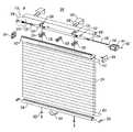
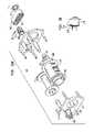
- FIG. 1shows an exploded view of a cordless blind assembly, in accordance with certain preferred embodiments of the present invention.
- FIGS. 2A-2Cshow a right hand headrail end cap for the assembly of FIG. 1 .
- FIGS. 3A-3Cshow a left hand headrail end cap for the assembly of FIG. 1 .
- FIG. 4shows a perspective end view of a headrail for the assembly of FIG. 1 .
- FIG. 5shows a perspective end view of a bottom rail for the assembly of FIG. 1 .
- FIG. 6shows end caps for the bottom rail of FIG. 5 .
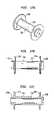
- FIG. 7shows a perspective view of a tensioning member for the assembly of FIG. 1 , in accordance with certain preferred embodiments of the present invention.
- FIG. 8Ashows a side view of the tensioning member of FIG. 7 , in accordance with further preferred embodiments of the present invention.
- FIG. 8Bshows a cross-sectional view of the tensioning member of FIG. 7 in a non-compressed position.
- FIG. 8Cshows the tensioning member of FIG. 8B in a compressed position.
- FIGS. 9A-9Cshow a large diameter collar for the tensioning member of FIG. 7 .
- FIGS. 10A-10Bshow a small diameter collar for the tensioning member of FIG. 7 .
- FIG. 11shows a compression spring for the tensioning member of FIG. 7 .
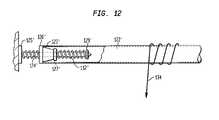
- FIG. 12shows a tensioning member for a cordless blind assembly, in accordance with further preferred embodiments of the present invention.
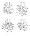
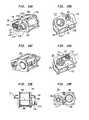
- FIGS. 13A and 13Bshow a right hand power plate for a spring motor for the cordless blind assembly shown in FIG. 1 .
- FIGS. 14A and 14Bshow a left hand power plate for a spring motor for the cordless blind assembly shown in FIG. 1 .
- FIGS. 15A and 15Bshow exploded views of a spring motor for the cordless blind assembly of FIG. 1 .
- FIG. 16shows a fragmentary view of the spring motor of FIG. 15A in an assembled configuration.
- FIGS. 17A-17Cshow a storage drum for the spring motor of FIG. 15A .
- FIGS. 18A-18Eshow an output drum for the spring motor of FIG. 15A .
- FIGS. 19A-19Fshow the spring motor of FIG. 15A after full assembly thereof.
- FIG. 20shows a drive shaft connectable with the spring motor of FIG. 15A .
- FIGS. 21A-21Cshow the drive shaft of FIG. 20 .
- FIG. 22shows the drive shaft of FIGS. 21A-21C connected with the spring motor of FIG. 15A .
- FIGS. 23A-23Eshow a cradle for the cordless blind assembly of FIG. 1 .
- FIGS. 24A-24Dshow a threaded support rod for the cordless blind assembly of FIG. 1 .
- FIGS. 25A-25Cshow a clip for the cordless blind assembly of FIG. 1 .
- FIGS. 26A-26Bshow a traversing tube for the cordless blind assembly of FIG. 1 .
- FIGS. 27A-27Bshow a pulley for the spring motor of FIG. 15A .
- FIGS. 28A-28Cshow a retainer ring for the spring motor of FIG. 15A .
- FIG. 29shows a perspective view of the tube of FIG. 26A coupled with the spring motor of FIG. 15A , in accordance with certain preferred embodiments of the present invention.
- FIG. 30shows the cordless blind assembly of FIG. 1 after assembly thereof, headrail in accordance with certain preferred embodiments of the present invention.
- FIG. 31shows another view of the assembly of FIG. 30 .
- FIG. 32shows another view of the assembly of FIG. 30 .
- FIG. 33shows another view of the assembly of FIG. 30 .
- FIG. 34shows the tensioning member of FIG. 7 between a traversing tube and a left hand headrail end cap, in accordance with certain preferred embodiments of the present invention.
- FIG. 35shows a cradle cover for the cordless blind assembly of FIG. 1 , in accordance with certain preferred embodiments of the present invention.
- FIG. 36shows the cradle cover of FIG. 35 assembled with a cradle and overlying a traversing tube.
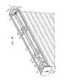
- FIG. 37shows a cradle for supporting a traversing tube with a lift cord passed through a window in the cradle in a zigzag path, in accordance with certain preferred embodiments of the present invention.
- FIG. 38shows an exploded view of a cordless blind assembly, in accordance with other preferred embodiments of the present invention.
- FIG. 39shows an end view of a headrail for the assembly of FIG. 38 .
- FIG. 40shows an end view of a bottom rail for the assembly of FIG. 38 .
- FIG. 41shows a headrail end cap for the headrail of FIG. 39 .
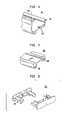
- FIG. 42shows bottom rail end caps for the bottom rail of FIG. 40 .
- FIG. 43shows a tie off for a lift cord for the assembly of FIG. 38 .
- FIG. 44shows an exploded view of a cordless blind assembly, in accordance with further preferred embodiments of the present invention.
- FIG. 45shows an end view of a headrail for the assembly of FIG. 44 .
- FIG. 46shows an end view of a bottom rail for the assembly of FIG. 44 .
- FIG. 47shows a headrail end cap for the headrail of FIG. 45 .
- FIG. 48shows a bottom rail end cap for the bottom rail of FIG. 46 .
- FIG. 49shows a tie off for a lift cord for the assembly of FIG. 44 .
- FIG. 1shows an exploded view of a cordless blind assembly, in accordance with certain preferred embodiments of the present invention.
- the assemblyincludes a headrail 102 , a left hand headrail end cap 104 and a right hand headrail end cap 106 .
- the left hand and right hand end caps 104 , 106cover the respective left and right ends of headrail 102 .
- the assemblyalso preferably includes a tensioning member 108 including a large diameter collar 110 , a compression spring 112 and a small diameter collar 114 .
- the cordless blind assembly 100desirably includes a first cradle 116 and a second cradle 118 assembled with headrail 102 .
- the assembly 100also includes a central cradle 120 . In certain preferred embodiments, however, the central cradle 120 is not required.
- the first and second cradles 116 , 118are adapted to support rotational and traversing movement of tube 122 .
- the cellular shade 100also includes threaded rod 124 and threaded plug 126 insertable into an opening at a first end of tube 122 .
- Cordless blind assembly 100also includes a first cradle cover 128 for assembly with first cradle 116 and a second cradle cover 130 for assembly with second cradle 118 .
- the cradle covers 128 , 130prevent lift cord slack from developing on one side of tube 122 as opposed to the other side of tube 122 .
- the cordless blind assembly 100also includes clips 132 attachable over the outer surface of tube 122 for holding ends of lift cord 134 in place.
- the assembly 100also includes a drive plug 136 insertable into an opening at a second end of tube 122 , and a drive shaft having 138 having a first end 140 adapted to engage an opening in drive plug 136 .
- Drive shaft 138has a second end. 142 engageable with a power assembly 144 , such as a spring motor.
- the drive shaftis adapted to translate rotational movement to the drive plug, however, the drive plug is able to slide along the drive shaft to facilitate traversing movement of tube 122 .
- the cordless blind assembly 100also preferably includes a mounting bracket 146 and mounting screws 148 for mounting the headrail 102 over a window opening.
- the assembly 100also preferably includes a dust cover 150 adapted to cover the upper side headrail 102 , as well as the traversing tube 122 and power assembly 144 disposed within headrail 102 .
- the assembly 100also includes a slat 152 assembled with an underside of headrail 102 .
- the slat 152engages an upper end of a window covering material 154 , such as cellular fabric for attaching the window covering material 154 with headrail 102 .
- the assembly 100includes a second slat 156 inserted into the bottommost cell of window covering material 154 .
- the second slat 156engages an upper face of bottom rail 158 for connecting bottom rail 158 with the window covering material 154 .
- the bottom rail 158includes openings at both ends adapted to receive bottom rail end caps 160 .
- the lift cord 134has a lower end that is passed through window covering material 154 , bottom rail 158 and washer 162 for tying off the bottom end of lift cord 134 and securing the bottom end against an underside of bottom rail 158 .
- the assemblyalso includes a handle 164 attached to bottom rail 158 .
- the cordless blind assembly 100also includes a screw 166 connectable with the power assembly 144 .
- the screw 166includes a head shaped to engage a notch formed in right hand headrail end cap 106 , so as to reliably secure power assembly 144 to headrail 102 and right hand headrail end cap 106 .
- FIGS. 2A-2Cshow right hand headrail end cap 106 including outer face 168 , inner face 170 and projections 172 engageable with slots formed at an end of the headrail shown in FIG. 1 .
- the inner face 170 of right hand headrail end cap 106includes a notch 174 adapted to receive and secure a head of screw 166 ( FIG. 1 ), which in turn secures the power assembly 144 to the headrail 102 ( FIG. 1 ).
- FIG. 3Ashows the left hand headrail end cap 104 of FIG. 1 including outer face 176 , inner face 178 and projections 180 extending from inner face 178 .
- the projections 180are adapted to engage slots formed in a left hand side of the headrail 102 of FIG. 1 .
- the left hand headrail end cap 104includes a notch 182 adapted to receive an end of threaded rod 124 ( FIG. 1 ).
- FIG. 4shows an end view of headrail 102 including an opening 184 having slots 186 formed therein adapted to receive the projections 172 of right hand headrail end cap 106 .
- FIG. 5shows an end view of bottom rail 158 including slots 188 formed therein.
- the assemblyincludes bottom rail end caps 160 .
- Each bottom rail end cap 160has projections 190 adapted to be inserted into the slots 188 of bottom rail 158 .
- a tensioning member 108is inserted between a headrail end cap (not shown) and the end of tube 122 remote from power assembly 144 ( FIG. 1 ).
- the tube 122has an opening at an end thereof adapted to receive threaded plug 126 .
- the threaded plugincludes a central threaded opening 190 ( FIG. 8B ) adapted to receive threaded rod 124 having a head 125 .
- the periphery of threaded plug 126has projections 127 adapted to engage internal notch 109 of large diameter collar 110 .
- the tensioning memberis assembled about the exterior of threaded rod 124 .
- Tensioning member 108includes large diameter collar 110 , small diameter collar 114 and compression spring 112 assembled between collars 110 , 114 .
- the compression spring 112is wound about threaded rod 124 .
- the tensioning memberwill place more holding force on the tube 122 as the bottom rail and the cellular fabric 154 are lowered down over the window opening. As the cellular fabric 154 is pulled down, the tube 122 will rotate for unwinding the lift cords and traverse to the left.
- the tensioning member 108includes a large diameter collar 110 , a small diameter collar 114 and a compression spring 112 assembled therebetween.
- the large diameter collar 110includes a central opening 192 extending therethrough for receiving threaded rod 124 of FIG. 7 .
- the larger diameter tubular cover 110also includes an outer notch 194 formed at an end thereof adapted to engage head 125 of threaded rod l 24 and an inner notch 109 .
- the tensioning member 108also includes the small diameter collar 114 having a central opening 196 adapted to receive threaded rod 124 ( FIG. 7 ).
- the compression spring 112is preferably a helically wound compression spring.
- FIG. 8Bshows tensioning member in an uncompressed position.
- the threaded plug 126 of tube 122engages small diameter collar 114 for compression spring 112 between large diameter collar 110 and small diameter collar 114 .
- the outer end of large diameter collarincludes a notch 194 that engages head 125 of threaded rod 124 for preventing rotational movement of large diameter collar 110 .
- the increasing force provided by the compression spring 112increases the axial force at the end of the tube 122 for resisting axial movement of tube 122 .
- large diameter collar 110includes an opening 198 sized to receive the compression spring 112 ( FIG. 8 A-C), an outer wall 200 defining the central opening 198 and a central hub 202 .
- the central hub 202includes a central bore 204 adapted to receive threaded rod 124 , so that threaded rod 124 ( FIG. 1 ) may pass therethrough.
- the large diameter collar 110also includes an outer notch 194 and an inner notch 109 . During compression of the tensioning member, the outer notch 194 engages the end cap and the inner notch 109 engages the end of tube 122 for preventing rotation of the tensioning member.
- the small diameter collar 114has an outer wall 206 defining a central opening 208 sized to enable the threaded rod 124 ( FIG. 1 ) to pass therethrough.
- the small diameter collar 114also includes a head 210 and a top face 212 adapted to engage the head 125 of threaded rod 124 ( FIG. 7 ).
- compression spring 112includes helically wound coils 214 .
- the compression springhas an opening at the first end 216 thereof adapted to receive the outer wall 206 of small diameter collar 114 .
- the compression spring 112also includes a second opening at the second end 218 adapted to receive the central hub 202 of large diameter collar 110 .
- FIG. 12shows a tensioning member for a cordless blind assembly, in accordance with further preferred embodiments of the present invention.
- the tensioning memberis located within tube 122 ′ having a first end 123 ′ with a threaded plug 126 ′ secured therein.
- the assemblyincludes a threaded rod 124 ′ having a first end, including a head 125 ′, and a second end threaded into the threaded opening of threaded plug 126 ′.
- a compression spring 112 ′is inserted over the second end of the threaded rod 124 ′ between washer 127 ′ and retainer 129 ′.
- the lift cord 134 ′is unwound from the tube and the tube 122 ′ traverses to the left. Leftward movement of the tube compresses compression spring 112 ′, which increases the axial force applied to the end of the tube.
- FIGS. 13A-13B and 14 A- 14 Bshow power plates for the power assembly 144 shown in FIG. 1 .
- right hand power plate 220includes a pair of large posts 222 a and 222 b , four smaller posts 224 a - 224 d , a stub shaft 226 , a large diameter hole 228 and a small diameter hole 230 .
- the right hand power plate 220also includes a stub shaft throughbore 232 for enabling a drive shaft to pass therethrough, as will be described in more detail below.
- the upper large post 222 apreferably includes a female opening 234 and the second large post 222 b includes a male end projection 236 .
- Each of the smaller posts 224 a - 224 ddesirably have male end projections 238 a - 238 d.
- the power assemblyalso includes a left hand power plate 240 having a pair of large posts 242 a and 242 b .
- the first large post 242 aincludes a male projection 244 and the second large post 242 b includes a female opening 246 .
- the large posts 222 a , 222 b , 242 a , 242 b of the respective right and left end power plates 220 , 240are adapted to snap-fit together.
- the left hand power plate 240also includes smaller posts 248 a - 248 d having female openings 250 a - 250 d .
- the left hand power plate 240includes a large diameter opening 252 and a small diameter opening 254 .
- FIGS. 15A and 15Bshow an exploded view of the power assembly of FIG. 1 , in accordance with certain preferred embodiments of the present invention.
- the power assemblyincludes right hand power plate 220 and left hand power plate 240 .
- the power assemblyalso includes storage drum 256 having opposing hubs 258 a , 258 b for rotating within small diameter openings 230 and 254 of the respective power plates.
- the assemblyalso includes an output drum 260 having an output drum gear 262 integrally molded thereto.
- the output drumincludes bearing surfaces 264 a , 264 b that rotate within large diameter openings 228 , 252 of the respective power plates.
- the power plate assembly 144also includes a pulley 266 adapted to be fit over stub shaft 226 , a timing belt 268 that engages pulley 266 and output drum gear 262 and a retainer ring 270 having inwardly projecting teeth 272 .
- the exploded assembly shown in FIGS. 15A and 15Bdoes not show a spring wrapped around storage drum and output drum 260 .
- the springpreferably travels under the storage drum 256 and over the output drum 260 in the direction indicated by the arrow designated 274 in FIGS. 15A and 15B .
- the springpreferably stores and releases tension from the power assembly.
- the right hand power plate 220includes screw anchor post 276 having an internally threaded opening 278 with screw 280 secured in the threaded opening 278 .
- Timing belt 268includes teeth 282 that mesh with teeth 284 on pulley 266 and teeth 286 on output drum gear 262 .
- Pulley 266includes an annular opening 288 that is adapted to receive stub shaft 226 so that the pulley 266 is free to rotate about stub shaft 226 .
- retainer 270preferably includes a curved face 290 that faces timing belt 268 for holding the timing belt in place over output drum gear 262 (not shown).
- FIGS. 17A-17Cshow storage drum 256 having an outer surface 292 , a first retaining surface 294 , a second retaining surface 296 , a first bearing surface 258 a and a second bearing surface 258 b.
- output drum 260has an outer spring engaging surface 298 , a first retaining surface 300 and a second retaining surface 302 .
- the output drum 260also includes first bearing surface 264 a and second bearing surface 264 b .
- An output drum gearis integrally molded to output drum 260 .
- the output drum gear 262includes teeth 286 and an hexagonal projection 304 projecting therefrom.
- the hexagonal projection 304is adapted to engage the teeth 272 of retainer ring 270 ( FIG. 15A ).
- the output drum 260includes one or more openings 306 extending through the outer wall 298 thereof for receiving and securing an end of a spring (not shown).
- FIGS. 19A-19Fshow the power assembly 144 after all the components described above have been assembled together.
- right hand power plate 220 and left hand power plate 240are snap fit together by large posts 222 a and 242 a .
- Pulley 266is assembled over the stub shaft (not shown) and output drum gear 262 projects through the large diameter opening 252 of the left hand power plate 240 .
- the timing belt 268has teeth 282 that mesh with the teeth 284 of pulley 266 , as well as the teeth (not shown) of the output drum gear 262 .
- Retainer ring 270is secured over hexagonal projection 304 for holding the timing belt 268 in engagement with the teeth of the output drum gear 262 .
- FIG. 19Bshows a right side perspective view of the assembly including screw 280 secured in threaded opening 278 of screw anchor post 276 .
- the large posts 222 B, 242 B of the opposing power plates 220 , 240are snap-fit together.
- FIG. 19Dshows timing belt 268 having teeth 282 that mesh with the teeth 284 of pulley 266 and the teeth 286 of output drum gear 262 .
- FIG. 19Eshows a top plan view of the power assembly 144 of the present invention including storage drum 256 and output drum 260 .
- Screw 280is adapted for engaging an end cap of the headrail for holding the power assembly 144 securely in place.
- Retainer ring 270holds timing belt 268 in proper engagement with output drum gear 262 and pulley 266 .
- FIG. 19Fshows storage drum 256 , output drum 260 and spring 306 passing between storage drum 256 and output drum 260 .
- the spring 306travels in the direction indicated by the arrow designated 274 .
- the springis utilized to store and release tension from the power assembly 144 .
- FIGS. 20 and 21 A- 21 Cshow a drive shaft 138 having a first end 140 and a second end 142 , the first end being adapted to mesh with the square opening 267 of pulley 266 .
- drive shaft 138has a square-shaped outer surface when viewed in cross-section. The square-shaped outer surface is best shown in FIG. 21C .
- drive shaft 138includes stop ring 310 , snap barbs 312 and bifurcated end 314 .
- the bifurcated end 314includes an upper arm 316 and a lower arm 318 that may be compressed toward one another. Referring to FIGS.
- the bifurcated end 314is inserted into the square shaped opening 276 of pulley 266 and passes through the opening 232 of stub shaft 226 .
- the arms 316 and 318are compressed together.
- the two arms 316 , 318are free to flex away from one another so that the retaining barbs 320 , 322 engage the inside surface of right hand power plate 220 for holding the drive shaft secured to the power plate.
- the retaining barbs 320 , 322are angled away from the tip of the bifurcated end 314 for increasing grip as axial load increases.
- FIG. 22shows the drive shaft 138 assembled with the power assembly 144 .
- FIGS. 23A-23Eshow a cradle 116 adapted to facilitate rotational and traversing movement of a tube 122 ( FIG. 1 ).
- the cradle 116includes a tube bearing surface 324 , a ladder drum bearing surface 326 and a securing element 328 adapted for securing cradle 116 to the headrail of the assembly.
- the cradlehas a side window 330 passing through a side wall 332 thereof.
- the cradlealso includes a ladder opening 334 adjacent a front end 336 of the cradle, a first opening 338 for a lift cord, a second opening 340 for a second lift cord and a second ladder opening 342 adjacent the rear end 344 of cradle 116 .
- FIGS. 24A-24Dshow a threaded rod 124 having a tip end 344 and head 125 remote from tip end 344 .
- the threaded rod 124includes threads 348 extending between tip end 344 and head 125 .
- Head 125includes a substantially V-shaped notch 350 formed therein. In other preferred embodiments, the V-shaped notch may have different geometric shapes.
- FIGS. 25A-25Cshow clip 132 , preferably made of a flexible material such as metal.
- the clip 132is fastened over the outer surface of tube 122 ( FIG. 26A ) for holding an end of cord 134 securely fastened to the tube 122 .
- FIGS. 26A and 26Bshow tube 122 having an outer surface 346 with elongated grooves 348 formed therein.
- the tubehas one elongated groove.
- the tubehas two, three or more elongated grooves.
- FIGS. 27A and 27Bshow pulley 266 having teeth 284 and a square shaped opening 267 formed at one end thereof.
- the square shaped opening 267is adapted to receive the square-shaped outer surface of the drive shaft so that the pulley 266 and drive shaft rotate simultaneously with one another.
- the opposite end of pulley 266includes an annular opening 269 adapted to engage the outer surface of stub shaft 226 ( FIG. 13A )
- FIGS. 28A-28Cshow retainer 270 including inwardly projecting teeth 272 .
- the retainer 270has a curved surface 290 .
- the retainer 270includes a substantially convex surface 291 opposite the curved surface 290 .
- FIG. 29shows the power assembly 144 of FIG. 15A coupled with tube 122 by drive shaft 138 .
- the tube 122has an opening at a right end thereof and a drive plug 136 inserted in the opening.
- the tubeis supported by a first cradle 116 and a second cradle 118 .
- the cradlesinclude bearing surfaces that facilitate rotational and traversing movement of tube 122 .
- the left end of tube 122is supported by end cap 104 having notch 182 formed therein for supporting a head of threaded rod 124 .
- the threaded rod 124is secured in threaded plug 126 attached to the end of tube 122 .
- FIG. 30shows another preferred embodiment of the present invention including power assembly 144 connected with tube 122 via drive shaft 138 .
- the drive shaft 138has a first end connected with the power assembly 144 and a second end which engages drive plug 136 secured in an opening of tube 122 .
- An opposite end of tube 122is secured to left hand headrail end cap 104 by head 125 of threaded rod 124 (not shown).
- the head 125 of threaded rod 124is secured within a notch 182 formed in left hand headrail end cap 104 .
- a tensioning member 108 including a compression spring 112is secured between the end of tube 122 and left hand headrail end cap 104 .
- a first cradle 116 and a second cradle 118support rotational and traversing movement of tube 122 .
- a cradle cover 130is coupled to first cradle 116 .
- FIG. 31shows another perspective view of a cordless blind assembly 100 including headrail 102 supporting power assembly 144 and tube 122 .
- the power assembly 144includes pulley 266 coupled with drive shaft 138 .
- tube 122rotates as the lift cords (not shown) are unwound from the tube 122 .
- rotation of tube 122drives drive shaft 138 , which in turn rotates pulley 266 .
- Rotation of pulley 266drives timing belt 268 which, in turn, rotates output drum gear 262 .
- Rotation of output drum gear 262rotates output drum 260 which takes up the spring stored on storage drum 256 .
- FIG. 32shows yet another view of the assembly of the present invention including headrail 102 and left hand end cap 104 supporting rotation of tube 122 .
- the assemblyincludes a first cradle 116 and a second cradle 118 .
- the first and second cradles 116 , 118support rotational and traversing movement of tube 122 .
- the first end of tube 122has secured therein a drive plug 136 with a preferably square opening 139 adapted to receive the square cross-sectional shaped drive rod (not shown).
- left hand headrail end cap 104includes a notch 182 for securing head 125 of threaded rod 124 .
- FIG. 33shows the second end of tube 122 including threaded plug 126 having a central opening 127 with threads 129 .
- the threads 129 of the threaded plug 126engage the external threads of threaded rod 124 ( FIG. 32 ).
- the tuberotates in the counterclockwise direction, the tube traverses to the right along the threaded rod for moving the second end of the tube 122 closer to the left-most end of headrail 102 .
- FIG. 34shows an expanded view of tensioning member 108 including large diameter collar 110 , small diameter collar 114 and compression spring 112 disposed between the large diameter collar 110 and the small diameter collar 114 .
- Threaded rod 124has a head 125 secured in notch 182 of left hand headrail end cap 104 .
- the assemblyincludes threaded plug 126 secured in an opening at the end of tube 122 for engaging the external threads (not shown) of threaded rod 124 .
- the tensioning member 108is secured between the threaded plug 126 and the left hand headrail end cap 104 . As the cellular shade is payed out, the tube 122 rotates in a direction indicated by arrow 400 .
- the tube 122moves to the right for abutting threaded plug 126 against small diameter collar 114 . Further rightward movement of tube 122 compresses the tensioning member 108 between the threaded plug 126 and the inner face of left hand headrail end cap 104 . Further paying out of the cellular shade results in further rightward movement of tube 122 for providing further axial force by the tensioning member 108 . As the cellular shade is lifted up toward the headrail 102 , the tube 122 rotates in an opposite direction from the direction indicated by arrow 400 and the tube moves leftward along the threaded rod 124 . This reduces the amount of compression upon the tensioning member 108 .
- FIG. 35shows a cradle cover 130 which may be assembled over a cradle 116 that supports a rotating tube.
- the cradle cover 130includes first and second opposing flanges 131 , 133 that facilitate securing the cradle cover 130 to cradle 116 .
- cradle cover 130is secured over cradle 116 so that tube 122 is moveable between the cradle 116 and the cradle cover 130 .
- Opposing flanges 131 and 133facilitate attachment of cradle cover 130 to cradle 116 .
- a side wall 117 of cradlepasses between opposing flanges 131 and 132 of cradle cover 130 .
- FIG. 37shows lift cord 134 wrapped around tube 122 .
- An end 135 of lift cord 134is secured in an elongated groove 348 and held in the groove 348 by clip 132 .
- the clippreferably covers the groove 348 for holding the end 135 of cord 134 in place so that the cord 134 does not move.
- the cordis then directed through lateral window 330 of cradle 116 and opening 340 extending through a bottom wall 341 of cradle 116 .
- the lift cord 134follows a zigzag path whereby the cord engages a periphery of window 330 and a periphery of opening 340 .
- the engagement of the cord with the edges of the openings 330 , 340creates friction that is believed to provide better holding force for the cordless blind assembly. This tends to hold the cellular shade in place as it is raised and lowered relative to the window opening.
- FIG. 38shows a pleated shade assembly 1100 in accordance with certain preferred embodiments of the present invention.
- the pleated shade assembly 1100is generally similar to the assembly shown in FIG. 1 , however, the window covering material is a pleated fabric 1154 .
- the assembly 1100includes a headrail 1102 and a bottom rail 1158 .
- the assemblyincludes headrail end caps 1104 and 1106 that cover the respective left and right ends of headrail 1102 shown in FIG. 39 .
- FIG. 42shows bottom rail end caps 1160 for capping the respective left and right ends of bottom rail 1158 shown in FIG. 40 .
- FIG. 43shows a tie off 1162 for tieing off an end of cord 1134 that has passed through bottom rail 1158 .
- a shade assembly 2100 in accordance with another preferred embodiment of the present inventionincludes aluminum slats 2154 , headrail 2102 , and bottom rail 2158 .
- the ends of the headrail 2102are covered by headrail end caps 2104 and 2106 .
- the openings at the ends of the bottom rail 2158are covered by the bottom rail end caps 2160 .
- the lower end of lift cord 2134is secured to bottom rail 2158 by tie-off 2164 .
Landscapes
- Engineering & Computer Science (AREA)
- Structural Engineering (AREA)
- Architecture (AREA)
- Civil Engineering (AREA)
- Blinds (AREA)
- Operating, Guiding And Securing Of Roll- Type Closing Members (AREA)
Abstract
Description
Claims (17)
Priority Applications (4)
| Application Number | Priority Date | Filing Date | Title |
|---|---|---|---|
| US10/393,328US7546866B2 (en) | 2003-03-20 | 2003-03-20 | Cordless blinds |
| US10/634,305US7143802B2 (en) | 2003-03-20 | 2003-08-05 | Cordless blinds |
| US11/143,231US20050217805A1 (en) | 2003-03-20 | 2005-06-02 | Cordless blinds |
| US11/542,722US20070039696A1 (en) | 2003-03-20 | 2006-10-03 | Cordless blinds |
Applications Claiming Priority (1)
| Application Number | Priority Date | Filing Date | Title |
|---|---|---|---|
| US10/393,328US7546866B2 (en) | 2003-03-20 | 2003-03-20 | Cordless blinds |
Related Child Applications (1)
| Application Number | Title | Priority Date | Filing Date |
|---|---|---|---|
| US10/634,305Continuation-In-PartUS7143802B2 (en) | 2003-03-20 | 2003-08-05 | Cordless blinds |
Publications (2)
| Publication Number | Publication Date |
|---|---|
| US20040182526A1 US20040182526A1 (en) | 2004-09-23 |
| US7546866B2true US7546866B2 (en) | 2009-06-16 |
Family
ID=32988124
Family Applications (1)
| Application Number | Title | Priority Date | Filing Date |
|---|---|---|---|
| US10/393,328Expired - LifetimeUS7546866B2 (en) | 2003-03-20 | 2003-03-20 | Cordless blinds |
Country Status (1)
| Country | Link |
|---|---|
| US (1) | US7546866B2 (en) |
Cited By (14)
| Publication number | Priority date | Publication date | Assignee | Title |
|---|---|---|---|---|
| US20080029229A1 (en)* | 2004-03-22 | 2008-02-07 | Grit Roetgering | Profiled Bar with a Raising Mechanism for a Window or Door Covering |
| USD636204S1 (en)* | 2010-08-09 | 2011-04-19 | Mariak Industries, Inc. | Window covering |
| US20130020034A1 (en)* | 2011-07-19 | 2013-01-24 | David Perkowitz | Window shade |
| WO2013033014A1 (en)* | 2011-08-26 | 2013-03-07 | Hunter Douglas Inc. | Cordless retractable roller shade for window coverings |
| US20140020854A1 (en)* | 2012-07-18 | 2014-01-23 | Hsien-Te Huang | Unlocking assembly for feedback window curtain set |
| US20150211295A1 (en)* | 2014-01-28 | 2015-07-30 | Chicology, Inc. | Curtains |
| US20150218879A1 (en)* | 2012-12-06 | 2015-08-06 | Hunter Douglas Inc. | End cap for a rail for a window covering |
| US9663980B2 (en) | 2015-09-18 | 2017-05-30 | Melvin N. Bakalar | Motorized window blind |
| US9896881B2 (en)* | 2015-11-09 | 2018-02-20 | Li-Ming Cheng | Fixing assembly for a shading body |
| US9903157B2 (en) | 2013-10-01 | 2018-02-27 | Hunter Douglas Industries B.V. | Rail for an architectural covering |
| US10036200B2 (en) | 2012-12-06 | 2018-07-31 | Hunter Douglas Inc. | Covering for an architectural opening |
| US11111722B2 (en)* | 2018-02-27 | 2021-09-07 | Suomen Visor Oy | End piece for a sunshade's edge rail and sunshade |
| US11549307B2 (en) | 2019-06-14 | 2023-01-10 | Edwin Torres | Corded top down and cordless bottom up shade modification kit |
| US11674350B2 (en) | 2011-08-26 | 2023-06-13 | Hunter Douglas Inc. | Feature for inhibiting light stripe between cellular elements in a covering for an architectural opening |
Families Citing this family (12)
| Publication number | Priority date | Publication date | Assignee | Title |
|---|---|---|---|---|
| US20070193703A1 (en)* | 2006-02-17 | 2007-08-23 | Li-Ming Cheng | Window coverings string coiler |
| US7686059B2 (en)* | 2006-09-05 | 2010-03-30 | Hunter Douglas Inc. | Top down/bottom up control system for retractable shade |
| US7624785B2 (en)* | 2007-07-19 | 2009-12-01 | Teh Yor Co., Ltd. | Self-raising window covering |
| US8549753B2 (en)* | 2009-05-14 | 2013-10-08 | Corning Incorporated | Methods of manufacturing a modular pulling roll |
| US8281843B2 (en) | 2010-04-16 | 2012-10-09 | Teh Yor Co., Ltd. | Actuator mechanism for venetian blinds |
| USD828052S1 (en)* | 2015-11-24 | 2018-09-11 | Kvadrat A/S | Mounting fixture for a roller blind box |
| CN105534256B (en)* | 2016-01-11 | 2017-10-31 | 浙江兆事达智能家居股份有限公司 | The convenient energy saving curtain rolling installed |
| CA2963414A1 (en)* | 2017-02-22 | 2018-08-22 | Sun Glow Window Covering Products of Canada Ltd. | Chain or cord cover for window treatments |
| USD939858S1 (en)* | 2020-05-05 | 2022-01-04 | Tser Wen Chou | Cord-lock cover for window blind |
| US12258813B2 (en)* | 2021-05-03 | 2025-03-25 | Securshade Inc. | Quick release window covering systems and methods of using the same |
| CN114876178B (en)* | 2022-05-13 | 2024-03-01 | 中交四公局第一工程有限公司 | Climbing frame clamping mechanism for building construction |
| CN119083879B (en)* | 2024-11-07 | 2025-03-21 | 山西凯得森建筑科技有限公司 | Aluminum alloy door and window with inward opening screen window structure |
Citations (65)
| Publication number | Priority date | Publication date | Assignee | Title |
|---|---|---|---|---|
| US13251A (en) | 1855-07-17 | Window-blind | ||
| US1434867A (en)* | 1919-12-24 | 1922-11-07 | Percy H Wilson | Venetian blind |
| US1756680A (en) | 1926-09-04 | 1930-04-29 | Wilson J G Corp | Venetian blind |
| US1798869A (en) | 1926-09-04 | 1931-03-31 | Wilson J G Corp | Venetian blind |
| US1801911A (en) | 1929-09-21 | 1931-04-21 | Wilson J G Corp | Venetian blind |
| US1808455A (en) | 1928-03-30 | 1931-06-02 | Wilson J G Corp | Venetian blind |
| US1845856A (en) | 1930-11-03 | 1932-02-16 | Kane Mfg Company | Traverse roller for venetian blinds |
| US1894833A (en) | 1932-05-16 | 1933-01-17 | Western Venetian Blind Co | Lifting and locking device for venetian blinds |
| US1978152A (en) | 1931-05-12 | 1934-10-23 | Kane Mfg Company | Traverse roller for venetian blinds |
| US2250106A (en) | 1938-11-29 | 1941-07-22 | Lorentzen Hardware Mfg Corp | Venetian blind head bar organization |
| US2266160A (en) | 1940-12-26 | 1941-12-16 | Columbia Mills Inc | Spring actuated blind |
| US2276716A (en) | 1941-03-17 | 1942-03-17 | Carlos J Cardona | Venetian blind |
| US2381060A (en)* | 1944-05-11 | 1945-08-07 | Lewis I Kahn | Venetian blind structure |
| US2420301A (en) | 1944-11-20 | 1947-05-13 | Cusumano Rudolph | Venetian blind |
| US2520629A (en) | 1948-04-22 | 1950-08-29 | Esposito John | Automatically operated venetian blind |
| US2824608A (en) | 1955-09-27 | 1958-02-25 | Chamberlain Corp | Venetian blind |
| US3141497A (en) | 1958-09-09 | 1964-07-21 | Griesser Ag | Venetian blind |
| US3192991A (en) | 1961-12-18 | 1965-07-06 | Levolor Lorentzen Inc | Venetian blind arrangement |
| US3352349A (en) | 1963-12-17 | 1967-11-14 | Hunter Douglas International | Venetian blind |
| US4326577A (en) | 1980-04-16 | 1982-04-27 | Tse Brian H | Vertically positioning window shading system |
| US4372432A (en) | 1981-03-18 | 1983-02-08 | General Clutch Corp. | Bi-directional clutch |
| US4574864A (en) | 1984-09-13 | 1986-03-11 | Tse Brian H | Vertically positioning window shading system |
| US4623012A (en) | 1983-12-27 | 1986-11-18 | General Clutch Corporation | Headrail hardware for hanging window coverings |
| US4813468A (en) | 1987-09-08 | 1989-03-21 | Hunter Douglas Inc. | Two and three position over-under window shade |
| US4825929A (en) | 1985-10-09 | 1989-05-02 | Elkhart Door, Inc. | Vehicular shade |
| US4852627A (en) | 1987-04-13 | 1989-08-01 | Daylighting, Inc. | Closed loop control system for shade assembly |
| US4880045A (en) | 1988-03-18 | 1989-11-14 | Stahler Deborah L | Window shade assembly |
| US4953610A (en) | 1989-03-17 | 1990-09-04 | Ultimate Window Coverings, Inc. | Double window shade assembly with independent shade movement |
| US5054162A (en) | 1990-08-17 | 1991-10-08 | Schlegel Corporation | Constant force compensation for power spring weight balance |
| US5067541A (en) | 1990-05-07 | 1991-11-26 | Coslett Fred L | Collapsible sun shade and method for shielding the sun |
| US5103888A (en) | 1990-12-28 | 1992-04-14 | Tachikawa Corporation | Blind slats lifting device |
| US5105867A (en) | 1990-05-07 | 1992-04-21 | Coslett Fred L | Collapsible sun shade and improved method for shielding the sun |
| US5133399A (en) | 1990-12-17 | 1992-07-28 | Hiller Jeffrey H | Apparatus by which horizontal and vertical blinds, pleated shades, drapes and the like may be balanced for "no load" operation |
| US5184660A (en) | 1991-11-01 | 1993-02-09 | Verosol Usa Inc. | Window blind activator |
| US5275221A (en)* | 1991-10-14 | 1994-01-04 | Doefix-Doehlemann Gmbh | Guide rod for window decorations or shading systems |
| US5318090A (en) | 1993-05-11 | 1994-06-07 | Chen Cheng Hsiung | Roller assembly for venetian blind |
| US5328113A (en) | 1992-01-30 | 1994-07-12 | Somfy | Device for winding the suspension cord of a blind |
| US5482100A (en) | 1994-04-06 | 1996-01-09 | Newell Operating Company | Cordless, balanced venetian blind or shade with consistent variable force spring motor |
| US5531257A (en) | 1994-04-06 | 1996-07-02 | Newell Operating Company | Cordless, balanced window covering |
| US5628356A (en) | 1995-03-06 | 1997-05-13 | Marocco; Norbert | Combined tilt and lift control for window coverings |
| US5706876A (en) | 1996-07-29 | 1998-01-13 | Lysyj; Phillip A. | Cordless, roller bar cellular shade |
| US5791390A (en) | 1997-02-06 | 1998-08-11 | Rollease, Inc. | Single control system for operating top-down-bottom-up shades |
| US5813447A (en) | 1996-07-29 | 1998-09-29 | Lysyj; Phillip A. | Cordless cellular and pleated shade |
| USRE35926E (en) | 1990-12-14 | 1998-10-20 | Nordicon Develop Aps | Venetian- or pleated blinds, particularly for multiple pane insulating glass window |
| US5857553A (en) | 1996-05-28 | 1999-01-12 | Somfy | Reducer with Oldham coupling |
| US6012506A (en) | 1999-01-04 | 2000-01-11 | Industrial Technology Research Institute | Venetian blind provided with slat-lifting mechanism having constant force equilibrium |
| US6024154A (en) | 1999-01-28 | 2000-02-15 | Industrial Technology Research Institute | Venetian blind lifting mechanism provided with concealed pull cords |
| US6056036A (en) | 1997-05-01 | 2000-05-02 | Comfortex Corporation | Cordless shade |
| US6076587A (en) | 1997-06-24 | 2000-06-20 | Holis Metal Industries Ltd. | Tilting mechanism for a venetian blind |
| US6095222A (en) | 1999-02-18 | 2000-08-01 | Newell Operating Co. | Lift cord adjustment system |
| EP1039092A2 (en) | 1999-03-23 | 2000-09-27 | Hunter Douglas Industries B.V. | Modular operating mechanism for coverings for architectural openings |
| US6135189A (en) | 1997-07-28 | 2000-10-24 | Weinreich; Steve | Mechanism for constant balance |
| US6149094A (en) | 1996-03-20 | 2000-11-21 | Barnes Group Inc. | Spring motor |
| US6158494A (en) | 1998-06-19 | 2000-12-12 | Huang; Shien-Te | Winding device for window covering |
| US6283192B1 (en) | 1997-11-04 | 2001-09-04 | Andrew J. Toti | Flat spring drive system and window cover |
| US6289965B1 (en) | 2000-02-11 | 2001-09-18 | Newell Operating Company | Take-up drum for a cordless shade counterbalance |
| US6330899B1 (en) | 1994-04-06 | 2001-12-18 | Newell Window Furnishings. Inc. | Cordless balanced window covering |
| US6338377B1 (en) | 2000-06-05 | 2002-01-15 | Harmonic Design, Incorporated | Skylight assembly with head rail-mounted actuator |
| US6575223B1 (en)* | 2002-01-16 | 2003-06-10 | Industrial Technology Research Institute | Concealed type lifting control mechanism for venetian blind |
| US6644373B2 (en) | 2001-11-08 | 2003-11-11 | Newell Window Furnishings, Inc. | Cordless blind |
| US6662850B2 (en) | 2002-03-07 | 2003-12-16 | Industrial Technology Research Institute | Lift coard concealable venetian blind lift control mechanism |
| US6708750B2 (en) | 2000-02-24 | 2004-03-23 | Techno Patenten B.V. | Control and motorization system |
| US6935398B2 (en) | 2002-05-06 | 2005-08-30 | Techniku Holding B.V. | Operating unit for a window covering |
| US7063122B2 (en) | 2002-03-20 | 2006-06-20 | Hunter Douglas Inc. | Bottom-up/top-down retractable cellular shade |
| US7143802B2 (en)* | 2003-03-20 | 2006-12-05 | Springs Window Fashions Lp | Cordless blinds |
Family Cites Families (4)
| Publication number | Priority date | Publication date | Assignee | Title |
|---|---|---|---|---|
| US1758680A (en)* | 1926-10-29 | 1930-05-13 | Henri G Andre | Rectifying apparatus |
| US5274001A (en)* | 1987-12-24 | 1993-12-28 | Borody Thomas J | Orthostatic lavage solutions |
| JPH0816061B2 (en)* | 1988-07-13 | 1996-02-21 | 森下ルセル株式会社 | Intestinal lavage fluid composition and intestinal lavage fluid |
| US6048901A (en)* | 1999-04-20 | 2000-04-11 | Braintree Laboratories, Inc. | Method of reducing intestinal gas, cramping and anorectal irritation |
- 2003
- 2003-03-20USUS10/393,328patent/US7546866B2/ennot_activeExpired - Lifetime
Patent Citations (70)
| Publication number | Priority date | Publication date | Assignee | Title |
|---|---|---|---|---|
| US13251A (en) | 1855-07-17 | Window-blind | ||
| US1434867A (en)* | 1919-12-24 | 1922-11-07 | Percy H Wilson | Venetian blind |
| US1756680A (en) | 1926-09-04 | 1930-04-29 | Wilson J G Corp | Venetian blind |
| US1798869A (en) | 1926-09-04 | 1931-03-31 | Wilson J G Corp | Venetian blind |
| US1808455A (en) | 1928-03-30 | 1931-06-02 | Wilson J G Corp | Venetian blind |
| US1801911A (en) | 1929-09-21 | 1931-04-21 | Wilson J G Corp | Venetian blind |
| US1845856A (en) | 1930-11-03 | 1932-02-16 | Kane Mfg Company | Traverse roller for venetian blinds |
| US1978152A (en) | 1931-05-12 | 1934-10-23 | Kane Mfg Company | Traverse roller for venetian blinds |
| US1894833A (en) | 1932-05-16 | 1933-01-17 | Western Venetian Blind Co | Lifting and locking device for venetian blinds |
| US2250106A (en) | 1938-11-29 | 1941-07-22 | Lorentzen Hardware Mfg Corp | Venetian blind head bar organization |
| US2266160A (en) | 1940-12-26 | 1941-12-16 | Columbia Mills Inc | Spring actuated blind |
| US2276716A (en) | 1941-03-17 | 1942-03-17 | Carlos J Cardona | Venetian blind |
| US2381060A (en)* | 1944-05-11 | 1945-08-07 | Lewis I Kahn | Venetian blind structure |
| US2420301A (en) | 1944-11-20 | 1947-05-13 | Cusumano Rudolph | Venetian blind |
| US2520629A (en) | 1948-04-22 | 1950-08-29 | Esposito John | Automatically operated venetian blind |
| US2824608A (en) | 1955-09-27 | 1958-02-25 | Chamberlain Corp | Venetian blind |
| US3141497A (en) | 1958-09-09 | 1964-07-21 | Griesser Ag | Venetian blind |
| US3192991A (en) | 1961-12-18 | 1965-07-06 | Levolor Lorentzen Inc | Venetian blind arrangement |
| US3352349A (en) | 1963-12-17 | 1967-11-14 | Hunter Douglas International | Venetian blind |
| US4326577A (en) | 1980-04-16 | 1982-04-27 | Tse Brian H | Vertically positioning window shading system |
| US4372432A (en) | 1981-03-18 | 1983-02-08 | General Clutch Corp. | Bi-directional clutch |
| US4623012A (en) | 1983-12-27 | 1986-11-18 | General Clutch Corporation | Headrail hardware for hanging window coverings |
| US4574864A (en) | 1984-09-13 | 1986-03-11 | Tse Brian H | Vertically positioning window shading system |
| US4825929A (en) | 1985-10-09 | 1989-05-02 | Elkhart Door, Inc. | Vehicular shade |
| US4852627A (en) | 1987-04-13 | 1989-08-01 | Daylighting, Inc. | Closed loop control system for shade assembly |
| US4813468A (en) | 1987-09-08 | 1989-03-21 | Hunter Douglas Inc. | Two and three position over-under window shade |
| US4880045A (en) | 1988-03-18 | 1989-11-14 | Stahler Deborah L | Window shade assembly |
| US4953610A (en) | 1989-03-17 | 1990-09-04 | Ultimate Window Coverings, Inc. | Double window shade assembly with independent shade movement |
| US5067541A (en) | 1990-05-07 | 1991-11-26 | Coslett Fred L | Collapsible sun shade and method for shielding the sun |
| US5105867A (en) | 1990-05-07 | 1992-04-21 | Coslett Fred L | Collapsible sun shade and improved method for shielding the sun |
| US5054162A (en) | 1990-08-17 | 1991-10-08 | Schlegel Corporation | Constant force compensation for power spring weight balance |
| USRE35926E (en) | 1990-12-14 | 1998-10-20 | Nordicon Develop Aps | Venetian- or pleated blinds, particularly for multiple pane insulating glass window |
| US5133399A (en) | 1990-12-17 | 1992-07-28 | Hiller Jeffrey H | Apparatus by which horizontal and vertical blinds, pleated shades, drapes and the like may be balanced for "no load" operation |
| US5103888A (en) | 1990-12-28 | 1992-04-14 | Tachikawa Corporation | Blind slats lifting device |
| US5275221A (en)* | 1991-10-14 | 1994-01-04 | Doefix-Doehlemann Gmbh | Guide rod for window decorations or shading systems |
| US5184660A (en) | 1991-11-01 | 1993-02-09 | Verosol Usa Inc. | Window blind activator |
| US5328113A (en) | 1992-01-30 | 1994-07-12 | Somfy | Device for winding the suspension cord of a blind |
| US5318090A (en) | 1993-05-11 | 1994-06-07 | Chen Cheng Hsiung | Roller assembly for venetian blind |
| US6079471A (en) | 1994-04-06 | 2000-06-27 | Newell Operating Company | Cordless, balanced window covering |
| US5482100A (en) | 1994-04-06 | 1996-01-09 | Newell Operating Company | Cordless, balanced venetian blind or shade with consistent variable force spring motor |
| US5531257A (en) | 1994-04-06 | 1996-07-02 | Newell Operating Company | Cordless, balanced window covering |
| US6330899B1 (en) | 1994-04-06 | 2001-12-18 | Newell Window Furnishings. Inc. | Cordless balanced window covering |
| US6234236B1 (en) | 1994-04-06 | 2001-05-22 | Newell Operating Company | Cordless balanced window covering |
| US5628356A (en) | 1995-03-06 | 1997-05-13 | Marocco; Norbert | Combined tilt and lift control for window coverings |
| US6149094A (en) | 1996-03-20 | 2000-11-21 | Barnes Group Inc. | Spring motor |
| US5857553A (en) | 1996-05-28 | 1999-01-12 | Somfy | Reducer with Oldham coupling |
| US6047759A (en)* | 1996-07-29 | 2000-04-11 | Lysyj; Phillip A. | Cordless cellular shade |
| US5960846A (en) | 1996-07-29 | 1999-10-05 | Lysyj; Phillip A. | Cordless cellular shade |
| US5706876A (en) | 1996-07-29 | 1998-01-13 | Lysyj; Phillip A. | Cordless, roller bar cellular shade |
| US5813447A (en) | 1996-07-29 | 1998-09-29 | Lysyj; Phillip A. | Cordless cellular and pleated shade |
| US5791390A (en) | 1997-02-06 | 1998-08-11 | Rollease, Inc. | Single control system for operating top-down-bottom-up shades |
| US6056036A (en) | 1997-05-01 | 2000-05-02 | Comfortex Corporation | Cordless shade |
| US6076587A (en) | 1997-06-24 | 2000-06-20 | Holis Metal Industries Ltd. | Tilting mechanism for a venetian blind |
| US6135189A (en) | 1997-07-28 | 2000-10-24 | Weinreich; Steve | Mechanism for constant balance |
| US6283192B1 (en) | 1997-11-04 | 2001-09-04 | Andrew J. Toti | Flat spring drive system and window cover |
| US6158494A (en) | 1998-06-19 | 2000-12-12 | Huang; Shien-Te | Winding device for window covering |
| US6012506A (en) | 1999-01-04 | 2000-01-11 | Industrial Technology Research Institute | Venetian blind provided with slat-lifting mechanism having constant force equilibrium |
| US6024154A (en) | 1999-01-28 | 2000-02-15 | Industrial Technology Research Institute | Venetian blind lifting mechanism provided with concealed pull cords |
| US6095222A (en) | 1999-02-18 | 2000-08-01 | Newell Operating Co. | Lift cord adjustment system |
| EP1039092A2 (en) | 1999-03-23 | 2000-09-27 | Hunter Douglas Industries B.V. | Modular operating mechanism for coverings for architectural openings |
| US6536503B1 (en)* | 1999-03-23 | 2003-03-25 | Hunter Douglas Inc. | Modular transport system for coverings for architectural openings |
| US6289965B1 (en) | 2000-02-11 | 2001-09-18 | Newell Operating Company | Take-up drum for a cordless shade counterbalance |
| US6708750B2 (en) | 2000-02-24 | 2004-03-23 | Techno Patenten B.V. | Control and motorization system |
| US6338377B1 (en) | 2000-06-05 | 2002-01-15 | Harmonic Design, Incorporated | Skylight assembly with head rail-mounted actuator |
| US6644373B2 (en) | 2001-11-08 | 2003-11-11 | Newell Window Furnishings, Inc. | Cordless blind |
| US6575223B1 (en)* | 2002-01-16 | 2003-06-10 | Industrial Technology Research Institute | Concealed type lifting control mechanism for venetian blind |
| US6662850B2 (en) | 2002-03-07 | 2003-12-16 | Industrial Technology Research Institute | Lift coard concealable venetian blind lift control mechanism |
| US7063122B2 (en) | 2002-03-20 | 2006-06-20 | Hunter Douglas Inc. | Bottom-up/top-down retractable cellular shade |
| US6935398B2 (en) | 2002-05-06 | 2005-08-30 | Techniku Holding B.V. | Operating unit for a window covering |
| US7143802B2 (en)* | 2003-03-20 | 2006-12-05 | Springs Window Fashions Lp | Cordless blinds |
Cited By (26)
| Publication number | Priority date | Publication date | Assignee | Title |
|---|---|---|---|---|
| US20080029229A1 (en)* | 2004-03-22 | 2008-02-07 | Grit Roetgering | Profiled Bar with a Raising Mechanism for a Window or Door Covering |
| USD636204S1 (en)* | 2010-08-09 | 2011-04-19 | Mariak Industries, Inc. | Window covering |
| US8851140B2 (en)* | 2011-07-19 | 2014-10-07 | Horizons Holdings, Llc | Window shade |
| US20130020034A1 (en)* | 2011-07-19 | 2013-01-24 | David Perkowitz | Window shade |
| US12404717B2 (en) | 2011-08-26 | 2025-09-02 | Hunter Douglas Inc. | Cordless retractable roller shade for window coverings |
| US10030439B2 (en) | 2011-08-26 | 2018-07-24 | Hunter Douglas Inc. | Cordless retractable roller shade for window coverings |
| US11674350B2 (en) | 2011-08-26 | 2023-06-13 | Hunter Douglas Inc. | Feature for inhibiting light stripe between cellular elements in a covering for an architectural opening |
| EP2747604A4 (en)* | 2011-08-26 | 2015-09-16 | Hunter Douglas | RETRACTABLE STORE WITHOUT AUTOMATIC WINDOW COVER CORD |
| US9353570B2 (en) | 2011-08-26 | 2016-05-31 | Hunter Douglas Inc. | Cordless retractable roller shade for window coverings |
| US11566469B2 (en) | 2011-08-26 | 2023-01-31 | Hunter Douglas Inc. | Cordless retractable roller shade for window coverings |
| US10907406B2 (en) | 2011-08-26 | 2021-02-02 | Hunter Douglas Inc. | Cordless retractable roller shade for window coverings |
| AU2012300285B2 (en)* | 2011-08-26 | 2017-11-23 | Hunter Douglas Inc. | Cordless retractable roller shade for window coverings |
| WO2013033014A1 (en)* | 2011-08-26 | 2013-03-07 | Hunter Douglas Inc. | Cordless retractable roller shade for window coverings |
| US20140020854A1 (en)* | 2012-07-18 | 2014-01-23 | Hsien-Te Huang | Unlocking assembly for feedback window curtain set |
| US10584528B2 (en) | 2012-12-06 | 2020-03-10 | Hunter Douglas Inc. | End cap for a rail for a window covering |
| US10036200B2 (en) | 2012-12-06 | 2018-07-31 | Hunter Douglas Inc. | Covering for an architectural opening |
| US9759008B2 (en)* | 2012-12-06 | 2017-09-12 | Hunter Douglas Inc. | End cap for a rail for a window covering |
| US11225831B2 (en) | 2012-12-06 | 2022-01-18 | Hunter Douglas Inc. | Covering for an architectural opening |
| US20150218879A1 (en)* | 2012-12-06 | 2015-08-06 | Hunter Douglas Inc. | End cap for a rail for a window covering |
| US9903157B2 (en) | 2013-10-01 | 2018-02-27 | Hunter Douglas Industries B.V. | Rail for an architectural covering |
| US10208534B2 (en) | 2013-10-01 | 2019-02-19 | Hunter Douglas Industries B.V. | Rail for an architectural covering |
| US20150211295A1 (en)* | 2014-01-28 | 2015-07-30 | Chicology, Inc. | Curtains |
| US9663980B2 (en) | 2015-09-18 | 2017-05-30 | Melvin N. Bakalar | Motorized window blind |
| US9896881B2 (en)* | 2015-11-09 | 2018-02-20 | Li-Ming Cheng | Fixing assembly for a shading body |
| US11111722B2 (en)* | 2018-02-27 | 2021-09-07 | Suomen Visor Oy | End piece for a sunshade's edge rail and sunshade |
| US11549307B2 (en) | 2019-06-14 | 2023-01-10 | Edwin Torres | Corded top down and cordless bottom up shade modification kit |
Also Published As
| Publication number | Publication date |
|---|---|
| US20040182526A1 (en) | 2004-09-23 |
Similar Documents
| Publication | Publication Date | Title |
|---|---|---|
| US7546866B2 (en) | Cordless blinds | |
| US7143802B2 (en) | Cordless blinds | |
| CN100470004C (en) | Brakes for cordless blinds | |
| CN100470005C (en) | One-way brake for cordless blinds | |
| CA2483736C (en) | Window covering lifting system and method | |
| US8739853B2 (en) | Cordless blind and operator device | |
| US5531257A (en) | Cordless, balanced window covering | |
| US5184660A (en) | Window blind activator | |
| KR102093760B1 (en) | Spring motor for drive for coverings for architectural openings | |
| CN101349139B (en) | Curtains that can be raised automatically | |
| US20040154758A1 (en) | Pull down, push up, shade apparatus | |
| AU2006207862A1 (en) | Worm gear drive mechanism for a covering for architectural openings | |
| MXPA04005316A (en) | Window covering with lifting mechanism. | |
| CN1211562C (en) | shielding device | |
| US20030111190A1 (en) | Brake for a cordless blind | |
| US10012020B2 (en) | Bi-directional clutch with return feature | |
| US20130112353A1 (en) | Cordless window blind assembly | |
| US11549307B2 (en) | Corded top down and cordless bottom up shade modification kit | |
| CN2635880Y (en) | One-way transmission device for lifting curtains and curtains using the same | |
| EP1994863A2 (en) | A window covering | |
| CN117145371A (en) | A rope winder, blinds and method for reducing the lifting and lowering jump of blinds | |
| WO2003054335A9 (en) | Lift cord for window blind | |
| MXPA00004822A (en) | Release brake for roller shades and other window coverings | |
| CA2589598A1 (en) | A window covering | |
| HK1081622B (en) | One way brake for a cordless blind |
Legal Events
| Date | Code | Title | Description |
|---|---|---|---|
| AS | Assignment | Owner name:SPRINGS WINDOW FASHIONS LP, WISCONSIN Free format text:ASSIGNMENT OF ASSIGNORS INTEREST;ASSIGNORS:STRAND, TORALF H.;WALKER, JEFF;RAISBECK, JAMES A.;AND OTHERS;REEL/FRAME:014370/0001 Effective date:20030805 | |
| AS | Assignment | Owner name:SPRINGS WINDOW FASHIONS LP, SOUTH CAROLINA Free format text:RECORD TO CORRECT ASSIGNEE'S NAME AND ADDRESS PREVIOUSLY RECORDED ON REEL 014370 FRAME 0001.;ASSIGNORS:STRAND, TORALF H.;WALKER, JEFF;RAISBECK, JAMES A.;AND OTHERS;REEL/FRAME:015686/0390 Effective date:20030805 | |
| AS | Assignment | Owner name:WACHOVIA BANK, NATIONAL ASSOCIATION, PENNSYLVANIA Free format text:SECURITY AGREEMENT;ASSIGNORS:SPRINGS INDUSTRIES, INC.;SPRINGS WINDOW FASHIONS, LLC;REEL/FRAME:019744/0986 Effective date:20070703 | |
| STCF | Information on status: patent grant | Free format text:PATENTED CASE | |
| AS | Assignment | Owner name:SPRINGS WINDOW FASHIONS, LLC, WISCONSIN Free format text:RELEASE OF SECURITY INTEREST;ASSIGNOR:WELLS FARGO BANK, NATIONAL ASSOCIATION;REEL/FRAME:026704/0475 Effective date:20110531 | |
| AS | Assignment | Owner name:JPMORGAN CHASE BANK, N.A., AS ADMINISTRATIVE AGENT Free format text:SECURITY AGREEMENT;ASSIGNOR:SPRINGS WINDOW FASHIONS, LLC;REEL/FRAME:026711/0668 Effective date:20110531 | |
| AS | Assignment | Owner name:JPMORGAN CHASE BANK, N.A., AS ADMINISTRATIVE AGENT Free format text:SECOND LIEN SECURITY AGREEMENT;ASSIGNOR:SPRINGS WINDOW FASHIONS, LLC;REEL/FRAME:026712/0024 Effective date:20110531 | |
| FPAY | Fee payment | Year of fee payment:4 | |
| AS | Assignment | Owner name:SPRINGS WINDOW FASHIONS, LLC, WISCONSIN Free format text:ASSIGNMENT OF ASSIGNORS INTEREST;ASSIGNOR:SPRINGS MEASURE AND INSTALL LP;REEL/FRAME:030499/0158 Effective date:20051230 Owner name:SPRINGS MEASURE AND INSTALL LP, WISCONSIN Free format text:ASSIGNMENT OF ASSIGNORS INTEREST;ASSIGNOR:SPRINGS WINDOW FASHIONS LP.;REEL/FRAME:030499/0259 Effective date:20051230 | |
| AS | Assignment | Owner name:SPRINGS WINDOW FASHIONS, LLC, WISCONSIN Free format text:RELEASE BY SECURED PARTY;ASSIGNOR:JPMORGAN CHASE BANK, N.A.;REEL/FRAME:030541/0295 Effective date:20130604 Owner name:GENERAL ELECTRIC CAPITAL CORPORATION, AS AGENT, CO Free format text:PATENT SECURITY AGREEMENT;ASSIGNOR:SPRINGS WINDOW FASHIONS, LLC;REEL/FRAME:030555/0046 Effective date:20130604 Owner name:SPRINGS WINDOW FASHIONS, LLC, WISCONSIN Free format text:RELEASE BY SECURED PARTY;ASSIGNOR:JPMORGAN CHASE BANK, N.A.;REEL/FRAME:030541/0225 Effective date:20130604 | |
| AS | Assignment | Owner name:U.S. BANK NATIONAL ASSOCIATION AS NOTES COLLATERAL Free format text:SECURITY AGREEMENT;ASSIGNOR:SPRINGS WINDOW FASHIONS, LLC;REEL/FRAME:030573/0108 Effective date:20130604 | |
| AS | Assignment | Owner name:WILMINGTON TRUST, NATIONAL ASSOCIATION, AS COLLATE Free format text:SECURITY INTEREST;ASSIGNORS:SPRINGS WINDOW FASHIONS, LLC;SUNSETTER PRODUCTS LIMITED PARTNERSHIP;HORIZONS HOLDINGS, LLC;AND OTHERS;REEL/FRAME:037515/0183 Effective date:20160106 | |
| AS | Assignment | Owner name:SPRINGS WINDOW FASHIONS, LLC, WISCONSIN Free format text:RELEASE BY SECURED PARTY;ASSIGNOR:WELLS FARGO BANK, NATIONAL ASSOCIATION (AS SUCCESSOR BY ASSIGNMENT TO GENERAL ELECTRIC CAPITAL CORPORATION);REEL/FRAME:039060/0911 Effective date:20160630 | |
| AS | Assignment | Owner name:JPMORGAN CHASE BANK, N.A., AS AGENT, ILLINOIS Free format text:SECURITY AGREEMENT;ASSIGNORS:SPRINGS WINDOW FASHIONS, LLC;HORIZONS HOLDINGS, LLC;SUNSETTER PRODUCTS LIMITED PARTNERSHIP;AND OTHERS;REEL/FRAME:039384/0228 Effective date:20160630 | |
| FPAY | Fee payment | Year of fee payment:8 | |
| AS | Assignment | Owner name:MECHOSHADE SYSTEMS, INC., NEW YORK Free format text:RELEASE OF SECURITY INTERESTS;ASSIGNOR:JPMORGAN CHASE BANK, N.A., AS COLLATERAL;REEL/FRAME:047269/0428 Effective date:20180615 Owner name:SPRINGS WINDOW FASHIONS, LLC, WISCONSIN Free format text:RELEASE OF SECURITY INTERESTS;ASSIGNOR:JPMORGAN CHASE BANK, N.A., AS COLLATERAL;REEL/FRAME:047269/0428 Effective date:20180615 Owner name:MARIAK INDUSTRIES, INC., CALIFORNIA Free format text:RELEASE OF SECURITY INTERESTS;ASSIGNOR:JPMORGAN CHASE BANK, N.A., AS COLLATERAL;REEL/FRAME:047269/0428 Effective date:20180615 Owner name:HORIZONS HOLDINGS, LLC, WISCONSIN Free format text:RELEASE OF SECURITY INTERESTS;ASSIGNOR:JPMORGAN CHASE BANK, N.A., AS COLLATERAL;REEL/FRAME:047269/0428 Effective date:20180615 Owner name:SUNSETTER PRODUCTS LIMITED, MASSACHUSETTS Free format text:RELEASE OF SECURITY INTERESTS;ASSIGNOR:JPMORGAN CHASE BANK, N.A., AS COLLATERAL;REEL/FRAME:047269/0428 Effective date:20180615 | |
| AS | Assignment | Owner name:SPRINGS WINDOW FASHIONS, LLC, WISCONSIN Free format text:RELEASE BY SECURED PARTY;ASSIGNOR:U.S. BANK NATIONAL ASSOCIATION AS NOTES COLLATERAL AGENT;REEL/FRAME:046122/0985 Effective date:20180615 | |
| AS | Assignment | Owner name:BARCLAYS BANK PLC AS COLLATERAL AGENT, NEW YORK Free format text:SECOND LIEN INTELLECTUAL PROPERTY SECURITY AGREEMENT;ASSIGNORS:SPRINGS INDUSTRIES, INC.;SPRINGS WINDOW FASHIONS, LLC;HORIZIONS HOLDINGS, LLC;AND OTHERS;REEL/FRAME:047433/0431 Effective date:20180615 Owner name:BARCLAYS BANK PLC AS COLLATERAL AGENT, NEW YORK Free format text:FIRST LIEN INTELLECTUAL PROPERTY SECURITY AGREEMENT;ASSIGNORS:SPRINGS INDUSTRIES, INC.;SPRINGS WINDOW FASHIONS, LLC;HORIZIONS HOLDINGS, LLC;AND OTHERS;REEL/FRAME:047433/0256 Effective date:20180615 | |
| MAFP | Maintenance fee payment | Free format text:PAYMENT OF MAINTENANCE FEE, 12TH YEAR, LARGE ENTITY (ORIGINAL EVENT CODE: M1553); ENTITY STATUS OF PATENT OWNER: LARGE ENTITY Year of fee payment:12 | |
| AS | Assignment | Owner name:WELLS FARGO BANK, NATIONAL ASSOCIATION, AS COLLATERAL AGENT, ILLINOIS Free format text:INTELLECTUAL PROPERTY SECURITY AGREEMENT;ASSIGNORS:SPRINGS WINDOW FASHIONS, LLC;MECHOSHADE SYSTEMS, LLC;MARIAK INDUSTRIES, INC.;AND OTHERS;REEL/FRAME:057822/0694 Effective date:20211006 Owner name:JPMORGAN CHASE BANK, N.A., AS COLLATERAL AGENT, DELAWARE Free format text:FIRST LIEN INTELLECTUAL PROPERTY SECURITY AGREEMENT;ASSIGNOR:SPRINGS WINDOW FASHIONS, LLC;REEL/FRAME:057723/0616 Effective date:20211006 | |
| AS | Assignment | Owner name:SUNSETTER PRODUCTS LIMITED PARTNERSHIP, MASSACHUSETTS Free format text:RELEASE OF SECOND LIEN INTELLECTUAL PROPERTY SECURITY AGREEMENT RECORDED AT R/F 047433/0431;ASSIGNOR:BARCLAYS BANK, PLC AS COLLATERAL AGENT;REEL/FRAME:057747/0896 Effective date:20211006 Owner name:MECHOSHADE SYSTEMS, LLC, NEW YORK Free format text:RELEASE OF SECOND LIEN INTELLECTUAL PROPERTY SECURITY AGREEMENT RECORDED AT R/F 047433/0431;ASSIGNOR:BARCLAYS BANK, PLC AS COLLATERAL AGENT;REEL/FRAME:057747/0896 Effective date:20211006 Owner name:MARIAK INDUSTRIES, INC., CALIFORNIA Free format text:RELEASE OF SECOND LIEN INTELLECTUAL PROPERTY SECURITY AGREEMENT RECORDED AT R/F 047433/0431;ASSIGNOR:BARCLAYS BANK, PLC AS COLLATERAL AGENT;REEL/FRAME:057747/0896 Effective date:20211006 Owner name:HORIZONS HOLDINGS, LLC, WISCONSIN Free format text:RELEASE OF SECOND LIEN INTELLECTUAL PROPERTY SECURITY AGREEMENT RECORDED AT R/F 047433/0431;ASSIGNOR:BARCLAYS BANK, PLC AS COLLATERAL AGENT;REEL/FRAME:057747/0896 Effective date:20211006 Owner name:SPRINGS WINDOW FASHIONS, LLC, WISCONSIN Free format text:RELEASE OF SECOND LIEN INTELLECTUAL PROPERTY SECURITY AGREEMENT RECORDED AT R/F 047433/0431;ASSIGNOR:BARCLAYS BANK, PLC AS COLLATERAL AGENT;REEL/FRAME:057747/0896 Effective date:20211006 Owner name:SPRINGS INDUSTRIES, INC., WISCONSIN Free format text:RELEASE OF SECOND LIEN INTELLECTUAL PROPERTY SECURITY AGREEMENT RECORDED AT R/F 047433/0431;ASSIGNOR:BARCLAYS BANK, PLC AS COLLATERAL AGENT;REEL/FRAME:057747/0896 Effective date:20211006 Owner name:SUNSETTER PRODUCTS LIMITED PARTNERSHIP, MASSACHUSETTS Free format text:RELEASE OF FIRST LIEN INTELLECTUAL PROPERTY SECURITY AGREEMENT RECORDED AT R/F 047433/0256;ASSIGNOR:BARCLAYS BANK, PLC AS COLLATERAL AGENT;REEL/FRAME:057747/0469 Effective date:20211006 Owner name:MECHOSHADE SYSTEMS, LLC, NEW YORK Free format text:RELEASE OF FIRST LIEN INTELLECTUAL PROPERTY SECURITY AGREEMENT RECORDED AT R/F 047433/0256;ASSIGNOR:BARCLAYS BANK, PLC AS COLLATERAL AGENT;REEL/FRAME:057747/0469 Effective date:20211006 Owner name:MARIAK INDUSTRIES, INC., CALIFORNIA Free format text:RELEASE OF FIRST LIEN INTELLECTUAL PROPERTY SECURITY AGREEMENT RECORDED AT R/F 047433/0256;ASSIGNOR:BARCLAYS BANK, PLC AS COLLATERAL AGENT;REEL/FRAME:057747/0469 Effective date:20211006 Owner name:HORIZONS HOLDINGS, LLC, WISCONSIN Free format text:RELEASE OF FIRST LIEN INTELLECTUAL PROPERTY SECURITY AGREEMENT RECORDED AT R/F 047433/0256;ASSIGNOR:BARCLAYS BANK, PLC AS COLLATERAL AGENT;REEL/FRAME:057747/0469 Effective date:20211006 Owner name:SPRINGS WINDOW FASHIONS, LLC, WISCONSIN Free format text:RELEASE OF FIRST LIEN INTELLECTUAL PROPERTY SECURITY AGREEMENT RECORDED AT R/F 047433/0256;ASSIGNOR:BARCLAYS BANK, PLC AS COLLATERAL AGENT;REEL/FRAME:057747/0469 Effective date:20211006 Owner name:SPRINGS INDUSTRIES, INC., WISCONSIN Free format text:RELEASE OF FIRST LIEN INTELLECTUAL PROPERTY SECURITY AGREEMENT RECORDED AT R/F 047433/0256;ASSIGNOR:BARCLAYS BANK, PLC AS COLLATERAL AGENT;REEL/FRAME:057747/0469 Effective date:20211006 | |
| AS | Assignment | Owner name:MECHOSHADE SYSTEMS, LLC, NEW YORK Free format text:RELEASE BY SECURED PARTY;ASSIGNOR:WILMINGTON TRUST, NATIONAL ASSOCIATION;REEL/FRAME:061448/0246 Effective date:20180615 Owner name:SUNSETTER PRODUCTS LIMITED PARTNERSHIP, MASSACHUSETTS Free format text:RELEASE BY SECURED PARTY;ASSIGNOR:WILMINGTON TRUST, NATIONAL ASSOCIATION;REEL/FRAME:061448/0246 Effective date:20180615 Owner name:HORIZON HOLDINGS, LLC, WISCONSIN Free format text:RELEASE BY SECURED PARTY;ASSIGNOR:WILMINGTON TRUST, NATIONAL ASSOCIATION;REEL/FRAME:061448/0246 Effective date:20180615 Owner name:SPRINGS WINDOW FASHIONS, LLC, WISCONSIN Free format text:RELEASE BY SECURED PARTY;ASSIGNOR:WILMINGTON TRUST, NATIONAL ASSOCIATION;REEL/FRAME:061448/0246 Effective date:20180615 | |
| AS | Assignment | Owner name:MECHOSHADE SYSTEMS, LLC, NEW YORK Free format text:RELEASE BY SECURED PARTY;ASSIGNOR:WILMINGTON TRUST, NATIONAL ASSOCIATION;REEL/FRAME:061875/0413 Effective date:20180615 Owner name:SUNSETTER PRODUCTS LIMITED PARTNERSHIP, MASSACHUSETTS Free format text:RELEASE BY SECURED PARTY;ASSIGNOR:WILMINGTON TRUST, NATIONAL ASSOCIATION;REEL/FRAME:061875/0413 Effective date:20180615 Owner name:HORIZON HOLDINGS, LLC, WISCONSIN Free format text:RELEASE BY SECURED PARTY;ASSIGNOR:WILMINGTON TRUST, NATIONAL ASSOCIATION;REEL/FRAME:061875/0413 Effective date:20180615 Owner name:SPRINGS WINDOW FASHIONS, LLC, WISCONSIN Free format text:RELEASE BY SECURED PARTY;ASSIGNOR:WILMINGTON TRUST, NATIONAL ASSOCIATION;REEL/FRAME:061875/0413 Effective date:20180615 | |
| AS | Assignment | Owner name:JPMORGAN CHASE BANK, N.A., AS COLLATERAL AGENT, ILLINOIS Free format text:SUPER-PRIORITY INTELLECTUAL PROPERTY SECURITY AGREEMENT;ASSIGNOR:SPRINGS WINDOW FASHIONS, LLC;REEL/FRAME:069747/0227 Effective date:20241219 | |
| AS | Assignment | Owner name:WILMINGTON TRUST, NATIONAL ASSOCIATION, AS NOTES COLLATERAL AGENT, MINNESOTA Free format text:SECURITY INTEREST;ASSIGNORS:SPRINGS WINDOW FASHIONS, LLC;MECHOSHADE SYSTEMS, LLC;MARIAK INDUSTRIES, INC.;AND OTHERS;REEL/FRAME:071382/0587 Effective date:20241219 | |
| AS | Assignment | Owner name:SPRINGS WINDOWS FASHIONS, LLC, WISCONSIN Free format text:RELEASE OF FIRST LIEN INTELLECTUAL PROPERTY SECURITY AGREEMENT AT R/F 057723/0616;ASSIGNOR:JPMORGAN CHASE BANK, N.A., AS COLLATERAL AGENT;REEL/FRAME:069848/0249 Effective date:20250102 |